

SlewingR ings
Technical Catalogue

3
CCONTENTS
Product overview
Examples of application
Assembly
Attributes
Quality
Functioning of slewing ring
Other atributes
Mounting
Markings
4
5
6
9
10
11
16
19
25
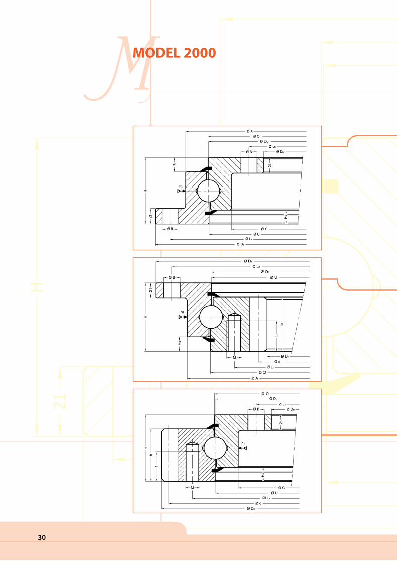
Model 2000:Single-row axial - ball bearing slewing rings without teethSingle-row axial - ball bearing slewing rings with internal gearSingle-row axial - ball bearing slewing rings with external gear
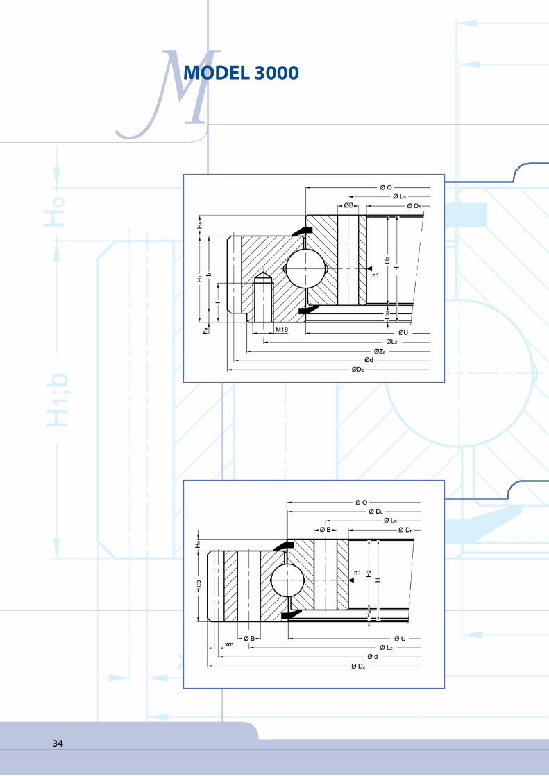
Model 3000:Single-row axial - ball bearing slewing rings without teeth Single-row axial - ball bearing slewing rings with external gearSingle-row axial - ball bearing slewing rings with internal gear
Model 4000:Double-row axial - ball bearing slewing rings with internal gear Double-row axial - ball bearing slewing rings with external gear
Model 5000:Single-row axial - roller bearing slewing rings with internal gear Single-row axial - roller bearing slewing rings with external gear
Model 7000:Three-row axial - radial roller bearing slewing rings with internal gear Three-row axial - radial roller bearing slewing rings with external gear
27
32
38
44
48

4
PPRODUCT OVERVIEW
Model Typ 2000Single-row ball bearing slewing rings
Model Typ 3000Single-row ball bearing slewing rings bearings
Model Typ 4000Double-row ball bearing slewing rings
Model Typ 5000Single-row roller bearing slewing rings
Model Typ 7000Three-row roller bearing slewing rings

5
TEXAMPLES OF APPLICATION
Examples of application:
Slewing rings connections are used in different revolving con-structions with the most frequent areas of their application compris-ing:
Production of revolving construction
cranes
Shipyard cranes
Airport cranes
Cranes mounted on vehicles
Workshop cranes; Earthwork ma-
chines Excavators
Shovel loaders
Stone-crushing machines, Excavators
with shovel-shaped wheels (anten-
nas)
Telescopes and periscopes; indus-
trial and welding robots Switchover
technologies
Naval technologies
Road and track vehicles, Naviga-
tion systems for vehicles, Recycling
machines
Armoured vehicles and tanks
Artillery

6
AASSEMBLY
MATERIALS
Rotis uses a variety of steel whose
differing structural conditions (nor-
malised or tempered) allow them to
be used for the most varied of appli-
cations whereby tempered steel is far
better suited for the manufacture of
both bearings and gears subjected to
higher load conditions than is normal-
ised steel.
For the manufacture of slewing rings
ROTIS defines the materials best suit-
ed for their intended application in
its product concepts catalogue. These
materials are then manufactured from
type-tested steel.
COMPONENTS
External or internal gear
Internal ring
Holes for fastening bolts
Raceway
Seal
Rollers or balls
Filler plug
Grease nipple

7
AASSEMBLY
Each step of production undergoes
controls ensuring the quality of the
products. In the majority of cases, fine
steel with carbon additives and alloys
are selected best suited to functional
requirements.
The tempering method through
quench hardening or artificial age-
ing is then selected when the forces
which the work pieces are subjected
to make this necessary.
MATERIALS
COMPARISON OF STANDARDS IN DIF-
FERENT COUNTRIES:
The table below displays our steel
standards in comparison with stand-
ards and material designations of oth-
er countries. The listed comparative
materials are those most similar to our
materials.
ADDITIONAL MATERIALS:
For specific applications or special
functional requirements the use of
special materials is recommended:
- stainless steel,
- hardened steel or alloys
- special tempered steel in controlled
atmospheres,
- steel subjected to carburisation or
nitration
- special steel for extremely low tem-
peratures
- light alloys on an aluminium basis.
LAND
GERMANY
ITALY
SPAIN
JAPAN
SWEDEN
U.S.A.
NORM
DIN
UNI
UNE
JIS
SSSTAHL
AISI
Ck 45
C45
C45K (F1140)
S45C
1672
16B45
42CrMo4
42CrMo4
42CrMo4 (F8232)
SNB7
2244
4142

8
AASSEMBLY
HEAT TREATMENT
A slewing ring conveys the force of a
bearing part to a stationary part of a
mechanism. The resulting load arising
from contact of the rolling element on
the raceway of the bearing is calcu-
lated according to Hertz’ theories and
modern criteria of plasticity.
ROTIS carries out local tempering in
order to fulfil requirements both in
the area of surface compression and
those regarding fatigue under the
surface. Through induction hardening
the required hardness as well as an ad-
equate depth hardness is achieved.
Through systematic manufacturing
controls, quality and equability during
heat treatment of the slewing rings
and conformity with ROTIS specifica-
tions is guaranteed.
This type of local tempering can also
be carried out on teeth when the cor-
responding forces require this and
when the geometry of the part allows
for this.
Additional methods of surface hard-
ening such as carburisation, nitration,
etc. can also be carried out.

9
AATTRIBUTES
TEMPERATURE
The temperature range for normal op-
eration of slewing rings lies between
-25°C and +70°C. Slewing rings for use
at lower or higher temperatures can
likewise be manufactured whereby a
special construction by our manufac-
turing department is required.
ENVIRONMENT
In cases with especially aggressive
environmental conditions such as:
- sea-air
- sand/coal (dusty and abrasive air),
the appropriate additional protection
measures must be taken such as for
example:
- affixation of labyrinth seals,
- installation of a housing,
- application of an oil lubrication.
These measures of protective mainte-
nance are fortified in order to ensure
normal operational conditions.
IMPACTS, VIBRATIONS
When slewing rings are subjected to
constant impacts or vibrations, this
fact must be stated in the product
specification book to ensure that the
manufacturing department takes this
into account with regard to the con-
struction.
ROTATIONAL SPEED
The reliable circumferential
speed for four point bearings
to 4 m/s,
short-term up to 5.5 m/s
and
at Typ 2000 2 m/s,
short-term 2.8 m/s.
The reliable circumferential speed for
roller bearings to 2 m/s,
short-term 2.8 m/s.

10
QQUALITY
CARE FOR PRODUCT QUALITY
Product quality is systematic and
complex with the objective of best
fulfilling the requirements of custom-
ers in all areas of the manufacturing
process.
Pre-manufacturing procedure:
- Service comprising expert client con-
sultation prior to sale
- Marketing – Incorporation of market-
ing needs and developmental trends
Manufacturing:
- modern manufacturing methods,
- techniques and tools,
- new materials and heat treatment
methods,
constant innovation of control meth-
ods and means,
- inspection of products at testing sta-
tions,
- constant improvement according to
TQM principles.
Post-manufacturing:
- quality control of products in opera-
tion with regard to improving their
use attributes
- after sales service – support in the
use of our products.

11
FFUNCTIONING OF A SLEWING RING
DETERMINING LOAD
The slewing ring which allows a con-
nection between a moving and a
stationary part must possess the re-
quired capacity to transfer force from
the moving part onto the stationary
part. The corresponding definition for
this capacity requires a precise knowl-
edge of the forces arising and their
subsequent effect on the slewing ring
including forces arising due to the
mass and the inertia of the payload
and substructure.
One must in this case differentiate be-
tween fixed loads, variable loads and
forces due to dynamic loads whereby
the two latter pose fatigue loads.
The knowledge of the direction of
forces with regard to the axis of the
ball bearing is necessary. One thus
distinguishes between:
The AXIS FORCES Fa, whose direc-
tion is parallel to the axis of rotation of
the slewing ring. The resultants from
these forces are called F axial forces.
The RADIAL FORCES Fr, which run
perpendicular to the axis of rota-
tion. The resultant forces are called F
radial forces.
TILTING MOMENT Mk
On the level parallel to the axis
of rotation. The resulting moment is
called MT and relates to the level on
which the axis of rotation lies.
ROTATIONAL MOMENT Md
Creates a shift in position of the
movable ring.
12
FFUNCTIONING OF A SLEWING RING
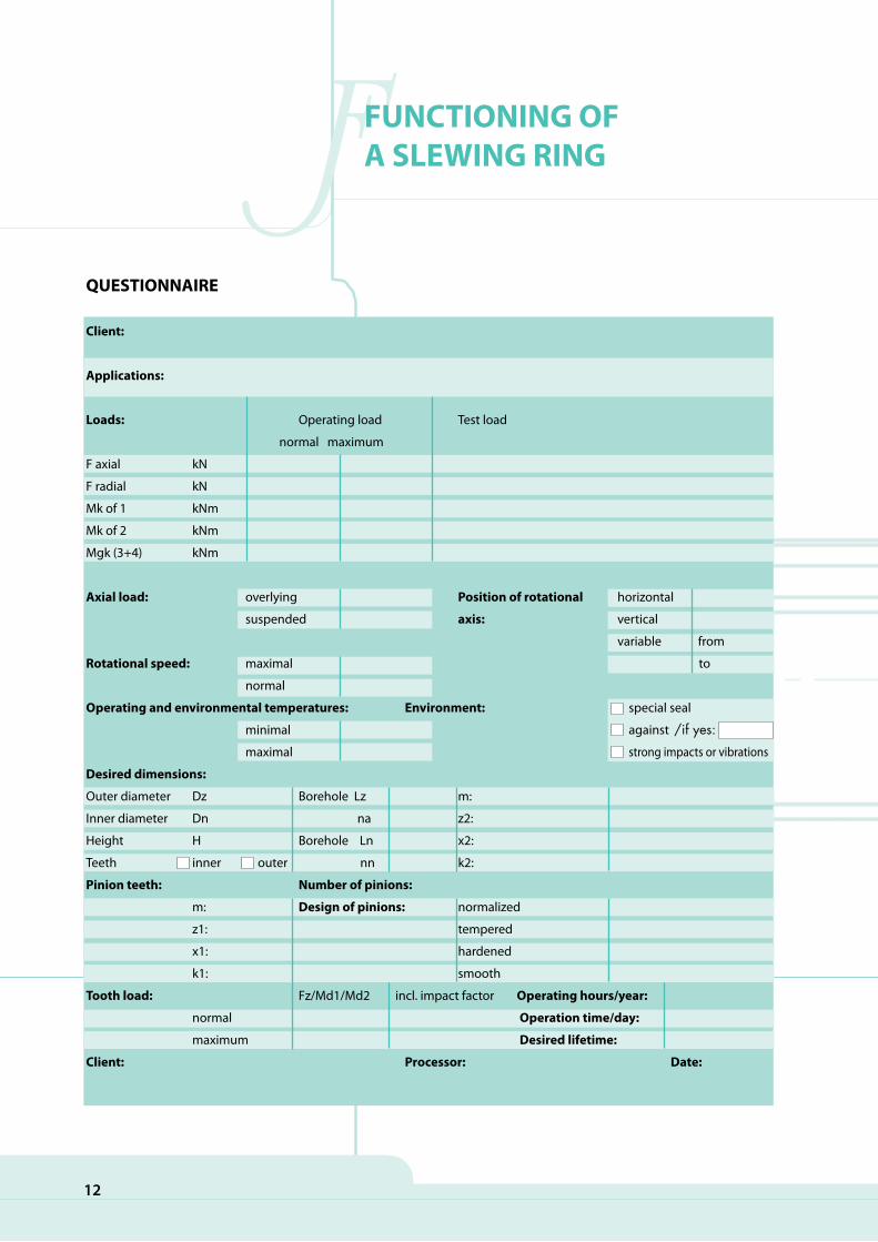
QUESTIONNAIRE
Client:
Applications:
Loads: Operating load Test load
normal maximum
F axial kN
F radial kN
Mk of 1 kNm
Mk of 2 kNm
Mgk (3+4) kNm
Axial load: overlying Position of rotational horizontal
suspended axis: vertical
variable from
Rotational speed: maximal to
normal
Operating and environmental temperatures: Environment: special seal
minimal against
maximal strong impacts or vibrations
Desired dimensions:
Outer diameter Dz Borehole Lz m:
Inner diameter Dn na z2:
Height H Borehole Ln x2:
Teeth inner outer nn k2:
Pinion teeth: Number of pinions:
m: Design of pinions: normalized
z1: tempered
x1: hardened
k1: smooth
Tooth load: Fz/Md1/Md2 incl. impact factor Operating hours/year:
normal Operation time/day:
maximum Desired lifetime:
Client: Processor: Date:
/if yes:
13
FFUNCTIONING OF A SLEWING RING
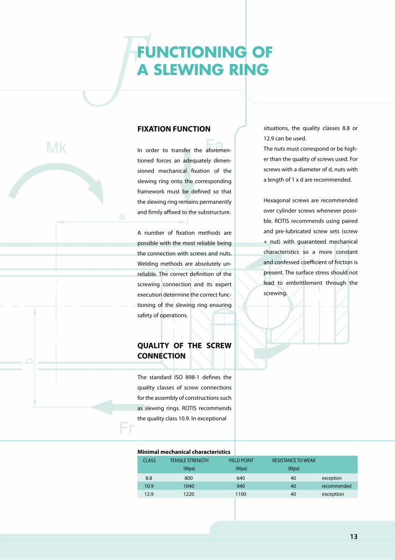
FIXATION FUNCTION
In order to transfer the aforemen-
tioned forces an adequately dimen-
sioned mechanical fixation of the
slewing ring onto the corresponding
framework must be defined so that
the slewing ring remains permanently
and firmly affixed to the substructure.
A number of fixation methods are
possible with the most reliable being
the connection with screws and nuts.
Welding methods are absolutely un-
reliable. The correct definition of the
screwing connection and its expert
execution determine the correct func-
tioning of the slewing ring ensuring
safety of operations.
QUALITY OF THE SCREW CONNECTION
The standard ISO 898-1 defines the
quality classes of screw connections
for the assembly of constructions such
as slewing rings. ROTIS recommends
the quality class 10.9. In exceptional
situations, the quality classes 8.8 or
12.9 can be used.
The nuts must correspond or be high-
er than the quality of screws used. For
screws with a diameter of d, nuts with
a length of 1 x d are recommended.
Hexagonal screws are recommended
over cylinder screws whenever possi-
ble. ROTIS recommends using paired
and pre-lubricated screw sets (screw
+ nut) with guaranteed mechanical
characteristics so a more constant
and confessed coefficient of friction is
present. The surface stress should not
lead to embrittlement through the
screwing.
8.810.912.9
80010401220
640940
1100
404040
CLASS TENSILE STRENGTH (Mpa)
YIELD POINT (Mpa)
RESISTANCE TO WEAR (Mpa)
exceptionrecommendedexception
Minimal mechanical characteristics
14
FFUNCTIONING OF A SLEWING RING
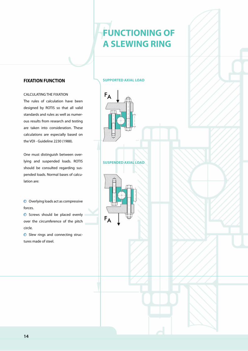
FIXATION FUNCTION
CALCULATING THE FIXATION
The rules of calculation have been
designed by ROTIS so that all valid
standards and rules as well as numer-
ous results from research and testing
are taken into consideration. These
calculations are especially based on
the VDI - Guideline 2230 (1988).
One must distinguish between over-
lying and suspended loads. ROTIS
should be consulted regarding sus-
pended loads. Normal bases of calcu-
lation are:
Overlying loads act as compressive
forces.
Screws should be placed evenly
over the circumference of the pitch
circle.
Slew rings and connecting struc-
tures made of steel.
SUSPENDED AXIAL LOAD
FA
SUPPORTED AXIAL LOAD
FA

Slew rings according to our rules:
thickness, stiffness, parallel (see the
chapter on additional constructions
on page 20).
Use of centring to avoid shearing
power on the screw connection when
large radial forces are present.
Splicing of the slew ring is also
advised when large radial forces are
present.
The length of the screw connec-
tion should be at least equal to five
times the diameter: LK ≥ 5 x d.
15
FFUNCTIONING OF A SLEWING RING
Track diameter (in mm) 500
25
750
30
1000
35
1250
40
1500
45
2000
55
2500
65
3000
80Minimum thickness(in mm)

16
OOTHER ATTRIBUTES
PRECISION – TOLERANCES
The general tolerances of standard
slewing rings are defined in the stand-
ards ISO 286- 1 and -2. For use entail-
ing higher precision requirements
such as for industrial robots, radar sys-
tems, etc. a higher degree of quality
can be achieved. The tolerance values
are evaluated according to the design
of the slewing ring. For slewing rings
with larger diameters and smaller
cross sections as well as for weaker
radial stiffness, these values must be
considered upon mounting on the
connecting structure in order to guar-
antee radial run-out.
GEOMETRYThe following criteria must be ad-
hered to:
All diameters: Js 13
All external centrings: f9
All internal centrings: H9
Total height: ± 1 mm
FIXATIONThe pitch circle diameters must fall
within class Js10 and have a minimum
tolerance of ± 0,2 mm.
TOOTH SYSTEMThe maximum radial run out error
is given in the diagram. The degree
of deviance for K teeth with the cor-
responding tolerance is also defined
in the drawing. This number also in-
cludes a proportion for tooth engage-
ment play.
TABLE OF GENERAL TOLERANCES (in compliance with ISO 286-2)
Diameter from(in mm) toInner centring H9 (in µm)Outer centring f9 (in µm)Diameter Js10 (in µm)Diameter Js13 (in µm)
180 250 315 400 500 630 800 1000 1250 1600 2000 2500250 315 400 500 630 800 1000 1250 1600 2000 2500 3150
+115 +130 +140 +155 +175 +200 +230 +260 +310 +370 +440 +540
-50 -56 -62 -68 -76 -80 -86 -98 -110 -120 -130 -145-165 -185 -202 -223 -251 -280 -316 -358 -420 -490 -570 -685
±92 ±105 ±115 ±125 ±140 ±160 ±180 ±210 ±250 ±300 ±350 ±430
±0,36 ±0,405 ±0,445 ±0,485 ±0,55 ±0,625 ±0,70 ±0,825 ±0,975 ±1,15 ±1,4 ±1,65

17
OOTHER ATTRIBUTES
RACEWAY AND RINGS
The PLANNED RUN-OUT ERROR of
the bearing surface is measured with
the aide of a dial gauge. The slewing
ring is rotated 360 degrees. The refer-
ence level is shown in the diagram on
the right.
The RADIAL ECCENTRICITY of the
centrings is also measured during the
rotation (see the diagram below).
These measurements are carried out
by placing the magnet base of the
dial gauge on the fixed ring whereby
the test prod touches the element
to be measured. The values are
measured during the rotation of the
rotating ring.
DL DL HO-DL
HO-DL
The TILTING PLAY under load
conditions is measured using the
following method: a normal force of
F is placed on a point on one of the
two rings right next to the bearing
race while the other ring remains
fixed on the rigid substructure. A dial
gauge with a rigid base is placed on
the other ring. In this way the screw
values under a force of F can be read.
This tilting play under load conditions
is measured for each slewing ring in
the work piece. These values are then
compared to permitted threshold
values and recorded.
18
OOTHER ATTRIBUTES
INSPECTION
If an excessive loss of lubricant is ob-
served upon subsequent
lubrication, the following should be
checked:
Whether the protective seal is still
in place,
Whether the seal is damaged (cuts,
tears, wearing),
Whether it warrants the due func-
tioning of the slewing ring.
This seal can be reinserted or re-
placed.
CORROSION PROTECTION
For special types of use, ROTIS can ap-
ply a corrosion protector on the sur-
faces, e.g.:
1. Galvanisation or galvanisation/bi-
chrome treatment
2. Phosphate coating
3. Chemical nickel plating
4. Paint coating
5. through 9. various treatments such
as chromisation, high temperature
galvanising, anodic oxidation, etc.
Please consult with the technical de-
partment.
SEALS
ROTIS slewing rings all have protec-
tive seals on both sides of the bearing
raceway. The protective seals func-
tions as:
Protection of the bearing raceway
against foreign particles from the out-
side,
Preservation of the lubricant inside
the bearing raceway.
CASING (METAL HOUSING)
For very difficult conditions of use and
in order to limit risks posed by the fol-
lowing foreign bodies:
filings,
frictional splinters,
welding grains,
splinters.
dirt,
sand,
sea water,
cutting fluids ...,
ROTIS strongly recommends the ap-
plication of effective protection. Also
when cleaning with solvents or when
using high pressure cleaners, it is rec-
ommended to avoid their application
to the protective seals.

19
MMOUNTING
INSPECTION – CONTROLS
Following the final tightening of all
fixation screws:
rotate the slewing ring at least
three times.
examine the value of the tooth
play over the complete perimeter
once more.
determine the tilting play with a
known load with regard to the meas-
uring points.
Methods:
Place the measuring instrument
between the two rings closest to the
bearing raceway on the main axle of
the load using a measuring accuracy
of at least 0.1 mm.
Set the calibration with the cali-
brated load to zero.
Place the load on the measure-
ment fixture.
Read the tilting play at the meas-
uring point.
A number of measurements
must be taken at various previously
marked points during continuous
operation.
The unevenness of the substruc-
ture and the tension force loss of the
screws depending on the position of
the measuring instrument must be
taken into consideration.
TRANSPORT
Because of the unstable construc-
tion of the rings, large anti-friction
bearings measuring 300 to 3500 mm
in various shapes must be especially
carefully transported.
Special boreholes have been pro-
vided for the conveyance of larger
bearings for retaining screws by
which the bearings can be clamped
and thus transported.
The bearings may only be trans-
ported and stored horizontally on an
even supporting area. Impacts on the
bearing especially radially should be
avoided. For longer storage periods,
it is recommended that bearings be
stored in dry and dust-free rooms
with a room temperature of between
-20º und 50º C. All bearings are pro-
tected against corrosion for a period
of approximately 12 months and the
raceway system has been greased
with the prescribed quality grease.
The tooth system is not greased and
must thus be greased immediately
upon its mounting.
20
MMOUNTING
ASSEMBLY
A large anti-friction bearing must be
installed in the connecting structure
very carefully and only by knowledge-
able workers – fitters. The instructions
of the manufacturer and general valid
requirements for the assembly of ex-
acting machine elements must be ob-
served.
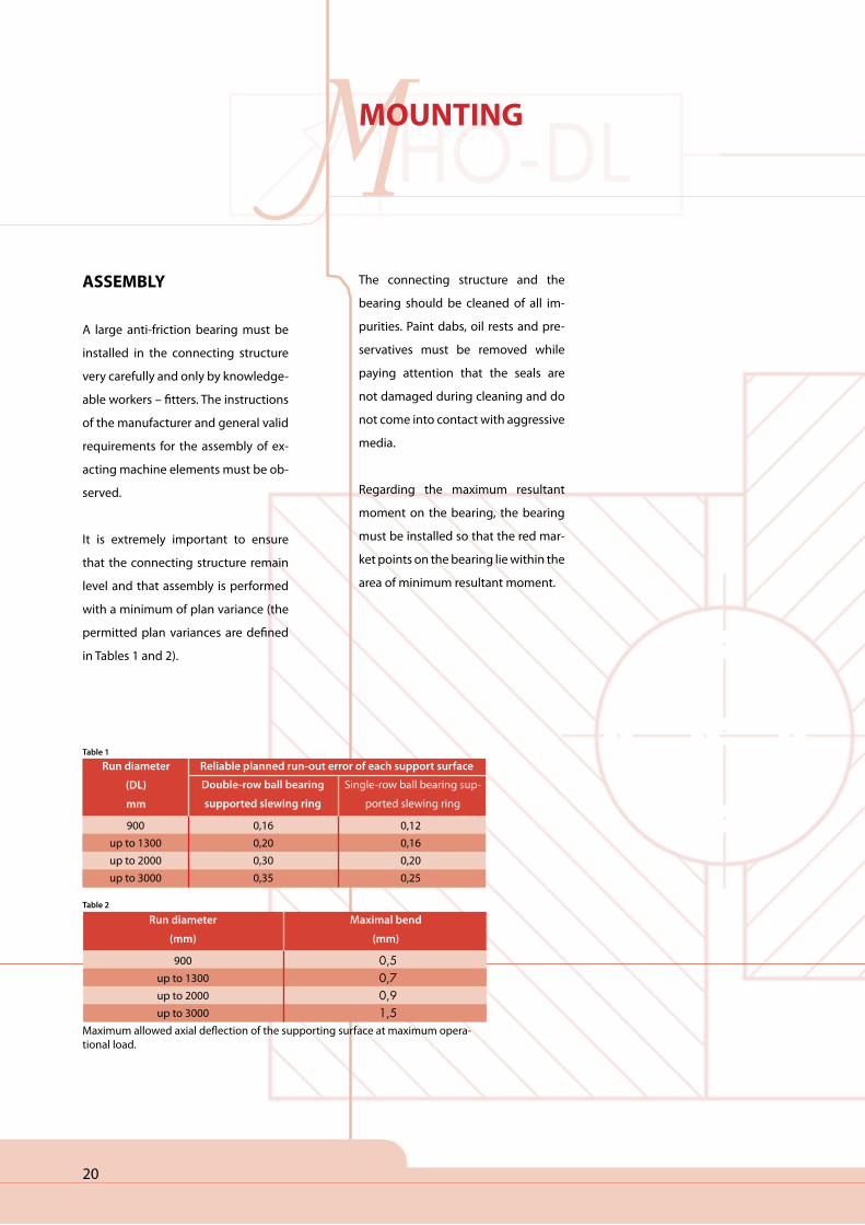
It is extremely important to ensure
that the connecting structure remain
level and that assembly is performed
with a minimum of plan variance (the
permitted plan variances are defined
in Tables 1 and 2).
Run diameter
(DL)
mm
Reliable planned run-out error of each support surface
Double-row ball bearing
supported slewing ring
Single-row ball bearing sup-
ported slewing ring
900up to 1300up to 2000up to 3000
0,160,200,300,35
0,120,160,200,25
Table 1
Run diameter
(mm)
Maximal bend
(mm)
900up to 1300up to 2000up to 3000
0,50,70,91,5
Maximum allowed axial deflection of the supporting surface at maximum opera-tional load.
Table 2
The connecting structure and the
bearing should be cleaned of all im-
purities. Paint dabs, oil rests and pre-
servatives must be removed while
paying attention that the seals are
not damaged during cleaning and do
not come into contact with aggressive
media.
Regarding the maximum resultant
moment on the bearing, the bearing
must be installed so that the red mar-
ket points on the bearing lie within the
area of minimum resultant moment.

21
MMOUNTING
The point at which the largest devia-
tion of the partial arc of the circle on
the gear wheel is marked in a green
colour. The bearing and as the case
may be, the gear wheel must be in-
stalled so that the lateral play amounts
to approximately 0.03 modules.
Extremely important during assembly
is the expert fixation of the bearing
onto the connecting structure. When
selecting screws, nuts and washers,
the recommendation of the manufac-
turer must be observed. The required
fixation of the screws and nuts are ap-
parent from the technical calculation
supplied with each offer and rendered
based on data of the requirements
and loads supplied to us by the buyer.
When the buyer fails to supply data
on the loads the bearing will bear, the
manufacturer can not warrant for the
correct choice of bearing. All screws
must be gradually and cross-wise
tightened using the prescribed tight-
ening torque.
The screws, nuts and washers should
be greased and only lightly oiled prior
to being tightened. Strongly lubri-
cated screws, nuts and washers have
a lower friction coefficient leading to a
larger resilience of the screws with the
same tightening torque.
In this case, the screws should be
tightened below the limiting value of
the prescribed tightening torque (Ta-
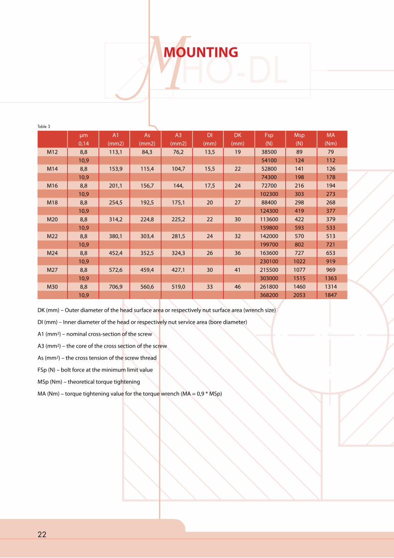
ble 3).
The screws are tightened using the
appropriate torque wrench. The tight-
ening torque value is listed in Table 3
together with the MA value.
For the tightening of screws with
threads exceeding M 30, we recom-
mend a special hydraulic tightening
device which can be ordered together
with the bearing.
Backlash
22
MMOUNTING
DK (mm) – Outer diameter of the head surface area or respectively nut surface area (wrench size)
DI (mm) – Inner diameter of the head or respectively nut service area (bore diameter)
A1 (mm2) – nominal cross-section of the screw
A3 (mm2) – the core of the cross section of the screw
As (mm2) – the cross tension of the screw thread
FSp (N) – bolt force at the minimum limit value
MSp (Nm) – theoretical torque tightening
MA (Nm) – torque tightening value for the torque wrench (MA = 0,9 * MSp)
M12
M14
M16
M18
M20
M22
M24
M27
M30
µm0,148,8
10,98,8
10,98,8
10,98,8
10,98,8
10,98,8
10,98,8
10,98,8
10,98,8
10,9
A1(mm2)113,1
153,9
201,1
254,5
314,2
380,1
452,4
572,6
706,9
As(mm2)
84,3
115,4
156,7
192,5
224,8
303,4
352,5
459,4
560,6
A3(mm2)
76,2
104,7
144,
175,1
225,2
281,5
324,3
427,1
519,0
DI(mm)13,5
15,5
17,5
20
22
24
26
30
33
DK(mm)
19
22
24
27
30
32
36
41
46
Fsp(N)
3850054100528007430072700
10230088400
124300113600159800142000199700163600230100215500303000261800368200
Msp(N)89
124141198216303298419422593570802727
10221077151514602053
MA(Nm)
79112126178194273268377379533513721653919969
136313141847
Table 3
23
MMOUNTING
OBSERVATION
Since the fixation of the large anti-
friction ring onto the connecting
structure with mounting screws is an
extremely important task, we would
once again like to emphasise that
this task only be carried out by expert
and trained fitters. The quality of the
screws and nuts as well as the torque
tension prescribed by the manufac-
turer should be strictly observed!
A retightening of the screws is re-
quired after 100 hours of operation
and should be subsequently checked
every 3 months.
BEARING MAINTENANCE
Once installed the bearing should be
greased on all grease points with the
prescribed lubricant until a fat collar
made of fresh grease builds up on the
entire circumference of the opening
of the bearing or respectively on the
seals. After inspecting the run systems
(correct lateral tooth play), the tooth
system should also be greased.
Lubricants can be used from lubricant
manufacturers recommended for spe-
cific operating conditions.
We recommend the following lubri-
cants:
The bearing should be correspond-
ingly greased according to defined
greasing periods. When regreasing
turn the bearing. In general, regrease
the bearing after every 100 hours of
operation. In more humid conditions,
strong temperature variations and
constant rotation, regreasing should
be repeated in shorter time intervals.
The manufacture of large anti-friction
bearings warrants a long life under
normal operating conditions and reg-
ular maintenance. Operational safety
is affected when bearing play during
a longer operational period increases.
Please consult with the manufacturer
regarding more details on maximum
reliable bearing play.
We ask you to consult with the manu-
facturer regarding all special wishes.
We are available for consultation and
help at all times.
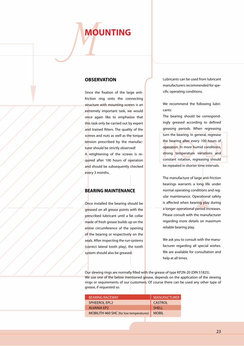
BEARING RACEWAYSPHEEROL EPL2ALVANIA EP2MOBILITH 460 SHC (for low temperatures)
MANUFACTURERCASTROLSHELLMOBIL
Our slewing rings are normally filled with the grease of type KP2N-20 (DIN 51825). We use one of the below mentioned grease, depends on the application of the slewing rings or requirements of our customers. Of course there can be used any other type of grease, if requested so.
24
MMAINTENANCE
INSPECTION OF THE POWER UNIT
When cleaning prior to relubrication
of the tooth system:
Ensure that no foreign particles are
in the tooth depth, slewing ring or on
the gear.
Check the regularity of the contact
area of the gear throughout the entire
tooth length
of the slewing ring and if needed cor-
rect the alignment of the axes.
Also check the value of tooth play.
MMARKINGS
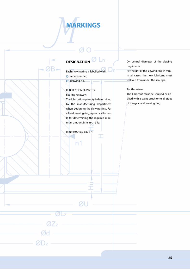
DESIGNATION
Each slewing ring is labelled with:
serial number,
drawing No.
LUBRICATION QUANTITY
Bearing raceway:
The lubrication quantity is determined
by the manufacturing department
when designing the slewing ring. For
a fixed slewing ring, a practical formu-
la for determining the required mini-
mum amount Mm in cm3 is:
Mm= 0,0045/3 x D x H
D= central diameter of the slewing
ring in mm.
H = height of the slewing ring in mm.
In all cases, the new lubricant must
leak out from under the seal lips.
Tooth system:
The lubricant must be sprayed or ap-
plied with a paint brush onto all sides
of the gear and slewing ring.
25

26
MMARKINGS
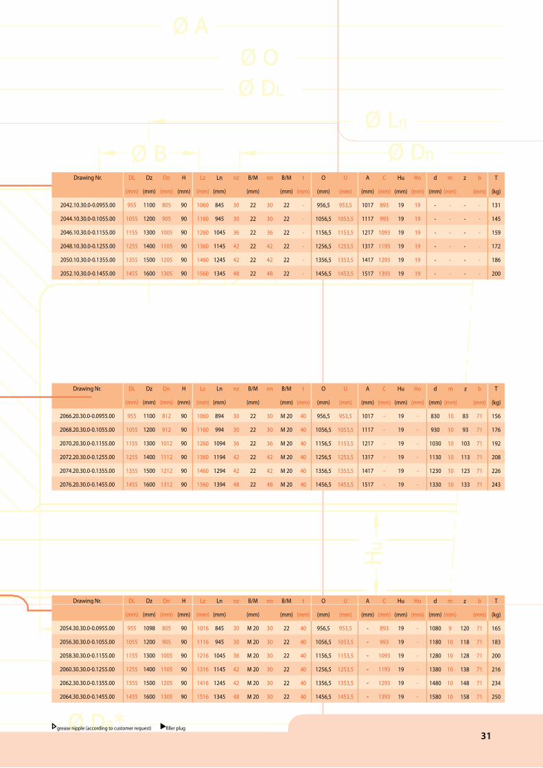
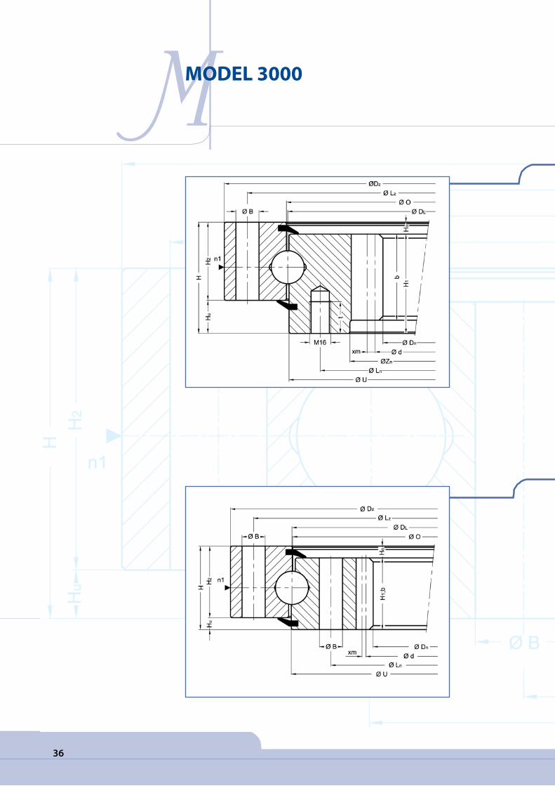
Description of terms used in the measurement tables
DzDnHLzLnnBMOU
H1H2HuHodmz
x.mbTt
Zuhu
Drawing No.Outer diameterInner diameter Overall heightExternal bolt circle diameterInternal bolt circle diameterNumber of bolt holes per hole circleBolt hole diameterBolt sizeDiameterDiameterRing heightRing heightDistance at bottom Outer ring / inner ringDistance at top Outer ring / inner ringGear P. C. D.ModuleNumber of teethAddendum modification sign per DIN 3960 October, 1976Tooth widthweightthread depthDiametertooth height
27
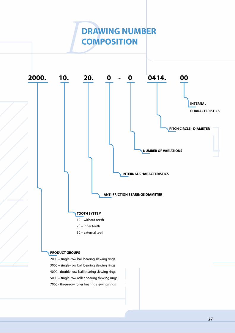
DDRAWING NUMBER COMPOSITION
2000. 10. 20. 0 - 0 0414. 00
INTERNAL
CHARACTERISTICS
PITCH CIRCLE - DIAMETER
NUMBER OF VARIATIONS
INTERNAL CHARACTERISTICS
ANTI-FRICTION BEARINGS DIAMETER
PRODUCT GROUPS
2000 – single-row ball bearing slewing rings
3000 – single-row ball bearing slewing rings
4000 - double-row ball bearing slewing rings
5000 – single-row roller bearing slewing rings
7000 - three-row roller bearing slewing rings
TOOTH SYSTEM
10 – without teeth
20 – inner teeth
30 – external teeth
28
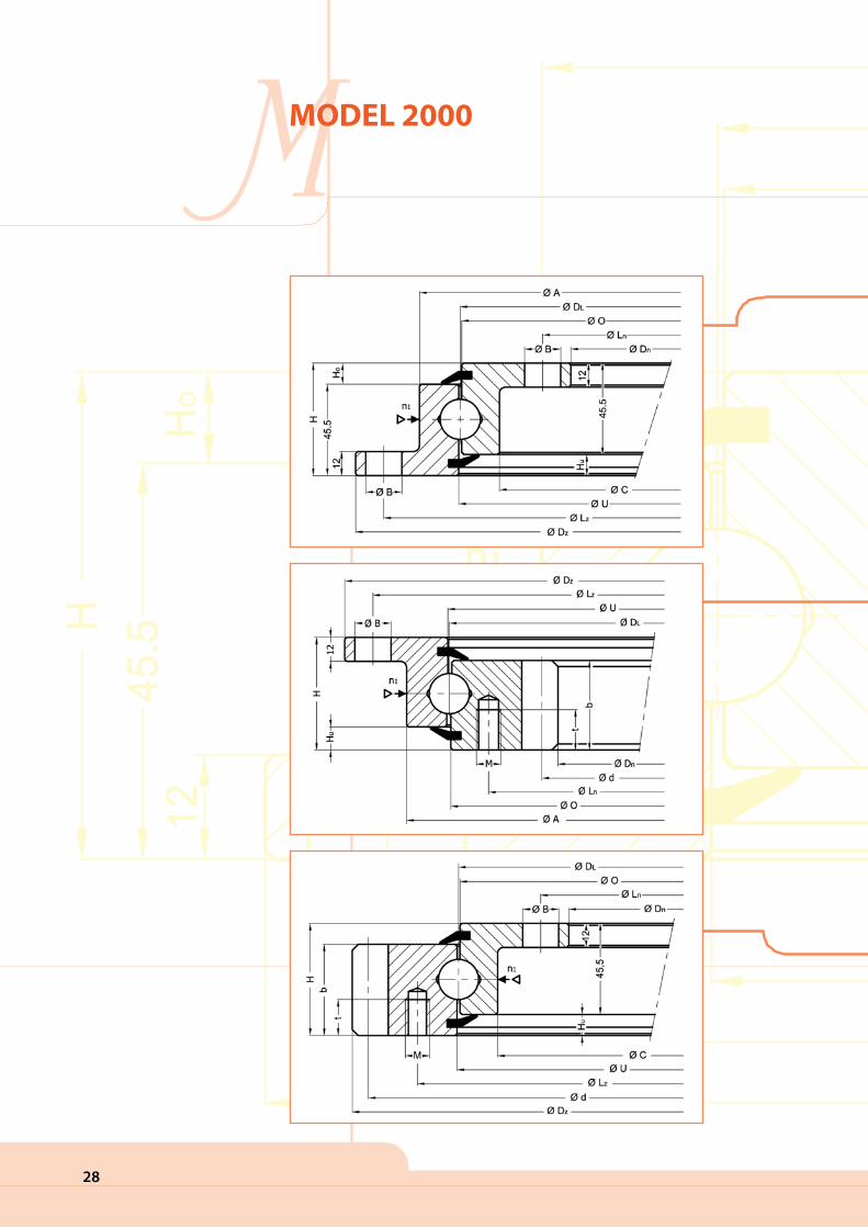
MMODEL 2000

29
Drawing Nr.
2000.10.20.0-0.0414.00
2002.10.20.0-0.0544.00
2004.10.20.0-0.0644.00
2006.10.20.0-0.0744.00
2008.10.20.0-0.0844.00
2010.10.20.0-0.0944.00
2012.10.20.0-0.1094.00
DL
(mm)
414
544
644
744
844
944
1094
Dz
(mm)
518
684
748
848
948
1048
1198
Dn
(mm)
304
434
534
634
734
834
984
H
(mm)
56
56
56
56
56
56
56
Lz
(mm)
490
620
720
820
920
1020
1170
Ln
(mm)
332
462
562
662
762
862
1012
nz
8
10
12
12
14
16
16
B/M
(mm)
18
18
18
18
18
18
18
nn
12
14
16
16
18
20
20
B/M
(mm)
18
18
18
18
18
18
18
t
(mm)
-
-
-
-
-
-
-
O
(mm)
412,5
542,5
642,5
742,5
842,5
942,5
1092,5
U
(mm)
415,5
545,5
645,5
745,5
845,5
945,5
1095,5
A
(mm)
453
583
683
783
883
983
1133
C
(mm)
375
505
605
705
805
905
1055
Hu
(mm)
10,5
10,5
10,5
10,5
10,5
10,5
10,5
Ho
(mm)
10,5
10,5
10,5
10,5
10,5
10,5
10,5
d
(mm)
-
-
-
-
-
-
-
m
(mm)
-
-
-
-
-
-
-
z
-
-
-
-
-
-
-
b
(mm)
-
-
-
-
-
-
-
T
(kg)
23,4
31,0
36,4
42,8
47,8
53,1
61,9
Drawing Nr.
2028.20.20.0-0.0414.00
2030.20.20.0-0.0544.00
2032.20.20.0-0.0644.00
2034.20.20.0-0.0744.00
2036.20.20.0-0.0844.00
2038.20.20.0-0.0944.00
2040.20.20.0-0.1094.00
DL
(mm)
414
544
644
744
844
944
1094
Dz
(mm)
518
648
748
848
948
1048
1198
Dn
(mm)
326,5
445,2
547,2
649,2
737,6
841,6
985,6
H
(mm)
56
56
56
56
56
56
56
Lz
(mm)
490
620
720
820
920
1020
1170
Ln
(mm)
375
505
605
705
805
905
1055
nz
8
10
12
12
14
16
16
B/M
(mm)
18
18
18
18
18
18
18
nn
12
16
18
20
20
22
24
B/M
(mm)
M 12
M 12
M 12
M 12
M 12
M 12
M 12
t
(mm)
20
20
20
20
20
20
20
O
(mm)
412,5
542,5
642,5
742,5
842,5
942,5
1092,5
U
(mm)
415,5
545,5
645,5
745,5
845,5
945,5
1095,5
A
(mm)
453
583
683
783
883
983
1133
C
(mm)
-
-
-
-
-
-
-
Hu
(mm)
10,5
10,5
10,5
10,5
10,5
10,5
10,5
Ho
(mm)
-
-
-
-
-
-
-
d
(mm)
335
456
558
660
752
856
1000
m
(mm)
5
6
6
6
8
8
8
z
67
76
93
110
94
107
125
b
(mm)
45,5
45,5
45,5
45,5
45,5
45,5
45,5
T
(kg)
27,1
36,9
43,7
51,1
61,6
65,8
80,7
Drawing Nr.
2014.30.20.0-0.0414.00
2016.30.20.0-0.0544.00
2018.30.20.0-0.0644.00
2020.30.20.0-0.0744.00
2022.30.20.0-0.0844.00
2024.30.20.0-0.0944.00
2026.30.20.0-0.1094.00
DL
(mm)
414
544
644
744
844
944
1094
Dz
(mm)
505
642
744
840
952
1048
1200
Dn
(mm)
304
434
534
634
734
834
984
H
(mm)
56
56
56
56
56
56
56
Lz
(mm)
455
585
685
785
885
985
1135
Ln
(mm)
322
462
652
662
762
862
1012
nz
10
14
16
18
18
20
22
B/M
(mm)
M 12
M 12
M 12
M 12
M 12
M 12
M 12
nn
12
14
16
16
18
20
20
B/M
(mm)
18
18
18
18
18
18
18
t
(mm)
20
20
20
20
20
20
20
O
(mm)
412,5
542,5
642,5
742,5
842,5
942,5
1092,5
U
(mm)
415,5
545,5
645,5
745,5
845,5
945,5
1095,5
A
(mm)
-
-
-
-
-
-
-
C
(mm)
375
505
605
705
805
905
1055
Hu
(mm)
10,5
10,5
10,5
10,5
10,5
10,5
10,5
Ho
(mm)
-
-
-
-
-
-
-
d
(mm)
495
630
732
828
936
1032
1184
m
(mm)
5
6
6
6
8
8
8
z
99
105
122
138
117
129
148
b
(mm)
45,5
45,5
45,5
45,5
45,5
45,5
45,5
T
(kg)
29,3
39,5
47,6
53,5
65,1
69,6
83,0
grease nipple (according to customer request) filler plug
Drawing Nr.
2066.20.30.0-0.0955.00
2068.20.30.0-0.1055.00
2070.20.30.0-0.1155.00
2072.20.30.0-0.1255.00
2074.20.30.0-0.1355.00
2076.20.30.0-0.1455.00
DL
(mm)
955
1055
1155
1255
1355
1455
Dz
(mm)
1100
1200
1300
1400
1500
1600
Dn
(mm)
812
912
1012
1112
1212
1312
H
(mm)
90
90
90
90
90
90
Lz
(mm)
1060
1160
1260
1360
1460
1560
Ln
(mm)
894
994
1094
1194
1294
1394
nz
30
30
36
42
42
48
B/M
(mm)
22
22
22
22
22
22
nn
30
30
36
42
42
48
B/M
(mm)
M 20
M 20
M 20
M 20
M 20
M 20
t
(mm)
40
40
40
40
40
40
O
(mm)
956,5
1056,5
1156,5
1256,5
1356,5
1456,5
U
(mm)
953,5
1053,5
1153,5
1253,5
1353,5
1453,5
A
(mm)
1017
1117
1217
1317
1417
1517
C
(mm)
-
-
-
-
-
-
Hu
(mm)
19
19
19
19
19
19
Ho
(mm)
-
-
-
-
-
-
d
(mm)
830
930
1030
1130
1230
1330
m
(mm)
10
10
10
10
10
10
z
83
93
103
113
123
133
b
(mm)
71
71
71
71
71
71
T
(kg)
156
176
192
208
226
243
30
MMODEL 2000
Drawing Nr.
2066.20.30.0-0.0955.00
2068.20.30.0-0.1055.00
2070.20.30.0-0.1155.00
2072.20.30.0-0.1255.00
2074.20.30.0-0.1355.00
2076.20.30.0-0.1455.00
DL
(mm)
955
1055
1155
1255
1355
1455
Dz
(mm)
1100
1200
1300
1400
1500
1600
Dn
(mm)
812
912
1012
1112
1212
1312
H
(mm)
90
90
90
90
90
90
Lz
(mm)
1060
1160
1260
1360
1460
1560
Ln
(mm)
894
994
1094
1194
1294
1394
nz
30
30
36
42
42
48
B/M
(mm)
22
22
22
22
22
22
nn
30
30
36
42
42
48
B/M
(mm)
M 20
M 20
M 20
M 20
M 20
M 20
t
(mm)
40
40
40
40
40
40
O
(mm)
956,5
1056,5
1156,5
1256,5
1356,5
1456,5
U
(mm)
953,5
1053,5
1153,5
1253,5
1353,5
1453,5
A
(mm)
1017
1117
1217
1317
1417
1517
C
(mm)
-
-
-
-
-
-
Hu
(mm)
19
19
19
19
19
19
Ho
(mm)
-
-
-
-
-
-
d
(mm)
830
930
1030
1130
1230
1330
m
(mm)
10
10
10
10
10
10
z
83
93
103
113
123
133
b
(mm)
71
71
71
71
71
71
T
(kg)
156
176
192
208
226
243
Drawing Nr.
2042.10.30.0-0.0955.00
2044.10.30.0-0.1055.00
2046.10.30.0-0.1155.00
2048.10.30.0-0.1255.00
2050.10.30.0-0.1355.00
2052.10.30.0-0.1455.00
DL
(mm)
955
1055
1155
1255
1355
1455
Dz
(mm)
1100
1200
1300
1400
1500
1600
Dn
(mm)
805
905
1005
1105
1205
1305
H
(mm)
90
90
90
90
90
90
Lz
(mm)
1060
1160
1260
1360
1460
1560
Ln
(mm)
845
945
1045
1145
1245
1345
nz
30
30
36
42
42
48
B/M
(mm)
22
22
22
22
22
22
nn
30
30
36
42
42
48
B/M
(mm)
22
22
22
22
22
22
t
(mm)
-
-
-
-
-
-
O
(mm)
956,5
1056,5
1156,5
1256,5
1356,5
1456,5
U
(mm)
953,5
1053,5
1153,5
1253,5
1353,5
1453,5
A
(mm)
1017
1117
1217
1317
1417
1517
C
(mm)
893
993
1093
1193
1293
1393
Hu
(mm)
19
19
19
19
19
19
Ho
(mm)
19
19
19
19
19
19
d
(mm)
-
-
-
-
-
-
m
(mm)
-
-
-
-
-
-
z
-
-
-
-
-
-
b
(mm)
-
-
-
-
-
-
T
(kg)
131
145
159
172
186
200
Drawing Nr.
2054.30.30.0-0.0955.00
2056.30.30.0-0.1055.00
2058.30.30.0-0.1155.00
2060.30.30.0-0.1255.00
2062.30.30.0-0.1355.00
2064.30.30.0-0.1455.00
DL
(mm)
955
1055
1155
1255
1355
1455
Dz
(mm)
1098
1200
1300
1400
1500
1600
Dn
(mm)
805
905
1005
1105
1205
1305
H
(mm)
90
90
90
90
90
90
Lz
(mm)
1016
1116
1216
1316
1416
1516
Ln
(mm)
845
945
1045
1145
1245
1345
nz
30
30
36
42
42
48
B/M
(mm)
M 20
M 20
M 20
M 20
M 20
M 20
nn
30
30
30
30
30
30
B/M
(mm)
22
22
22
22
22
22
t
(mm)
40
40
40
40
40
40
O
(mm)
956,5
1056,5
1156,5
1256,5
1356,5
1456,5
U
(mm)
953,5
1053,5
1153,5
1253,5
1353,5
1453,5
A
(mm)
-
-
-
-
-
-
C
(mm)
893
993
1093
1193
1293
1393
Hu
(mm)
19
19
19
19
19
19
Ho
(mm)
-
-
-
-
-
-
d
(mm)
1080
1180
1280
1380
1480
1580
m
(mm)
9
10
10
10
10
10
z
120
118
128
138
148
158
b
(mm)
71
71
71
71
71
71
T
(kg)
165
183
200
216
234
250
grease nipple (according to customer request) filler plug
31

32
MMODEL 3000
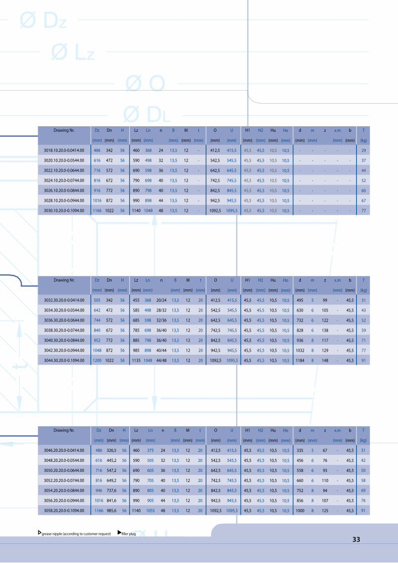
33grease nipple (according to customer request) filler plug
Drawing Nr.
3032.30.20.0-0.0414.00
3034.30.20.0-0.0544.00
3036.30.20.0-0.0644.00
3038.30.20.0-0.0744.00
3040.30.20.0-0.0844.00
3042.30.20.0-0.0944.00
3044.30.20.0-0.1094.00
Dz
(mm)
505
642
744
840
952
1048
1200
Dn
(mm)
342
472
572
672
772
872
1022
H
(mm)
56
56
56
56
56
56
56
Lz
(mm)
455
585
685
785
885
985
1135
Ln
(mm)
368
498
598
698
798
898
1048
n
20/24
28/32
32/36
36/40
36/40
40/44
44/48
B
(mm)
13,5
13,5
13,5
13,5
13,5
13,5
13,5
M
(mm)
12
12
12
12
12
12
12
t
(mm)
20
20
20
20
20
20
20
O
(mm)
412,5
542,5
642,5
742,5
842,5
942,5
1092,5
U
(mm)
415,5
545,5
645,5
745,5
845,5
945,5
1095,5
H1
(mm)
45,5
45,5
45,5
45,5
45,5
45,5
45,5
H2
(mm)
45,5
45,5
45,5
45,5
45,5
45,5
45,5
Hu
(mm)
10,5
10,5
10,5
10,5
10,5
10,5
10,5
d
(mm)
495
630
732
828
936
1032
1184
m
(mm)
5
6
6
6
8
8
8
z
99
105
122
138
117
129
148
x.m
(mm)
-
-
-
-
-
-
-
b
(mm)
45,5
45,5
45,5
45,5
45,5
45,5
45,5
T
(kg)
31
43
52
59
71
77
91
Ho
(mm)
10,5
10,5
10,5
10,5
10,5
10,5
10,5
Drawing Nr.
3018.10.20.0-0.0414.00
3020.10.20.0-0.0544.00
3022.10.20.0-0.0644.00
3024.10.20.0-0.0744.00
3026.10.20.0-0.0844.00
3028.10.20.0-0.0944.00
3030.10.20.0-0.1094.00
Dz
(mm)
486
616
716
816
916
1016
1166
Dn
(mm)
342
472
572
672
772
872
1022
H
(mm)
56
56
56
56
56
56
56
Lz
(mm)
460
590
690
790
890
990
1140
Ln
(mm)
368
498
598
698
798
898
1048
n
24
32
36
40
40
44
48
B
(mm)
13,5
13,5
13,5
13,5
13,5
13,5
13,5
M
(mm)
12
12
12
12
12
12
12
t
(mm)
-
-
-
-
-
-
-
O
(mm)
412,5
542,5
642,5
742,5
842,5
942,5
1092,5
U
(mm)
415,5
545,5
645,5
745,5
845,5
945,5
1095,5
H1
(mm)
45,5
45,5
45,5
45,5
45,5
45,5
45,5
H2
(mm)
45,5
45,5
45,5
45,5
45,5
45,5
45,5
Hu
(mm)
10,5
10,5
10,5
10,5
10,5
10,5
10,5
d
(mm)
-
-
-
-
-
-
-
m
(mm)
-
-
-
-
-
-
-
z
-
-
-
-
-
-
-
x.m
(mm)
-
-
-
-
-
-
-
b
(mm)
-
-
-
-
-
-
-
T
(kg)
29
37
44
52
60
67
77
Ho
(mm)
10,5
10,5
10,5
10,5
10,5
10,5
10,5
Drawing Nr.
3046.20.20.0-0.0414.00
3048.20.20.0-0.0544.00
3050.20.20.0-0.0644.00
3052.20.20.0-0.0744.00
3054.20.20.0-0.0844.00
3056.20.20.0-0.0944.00
3058.20.20.0-0.1094.00
Dz
(mm)
486
616
716
816
946
1016
1166
Dn
(mm)
326,5
445,2
547,2
649,2
737,6
841,6
985,6
H
(mm)
56
56
56
56
56
56
56
Lz
(mm)
460
590
690
790
890
990
1140
Ln
(mm)
375
505
605
705
805
905
1055
n
24
32
36
40
40
44
48
B
(mm)
13,5
13,5
13,5
13,5
13,5
13,5
13,5
M
(mm)
12
12
12
12
12
12
12
t
(mm)
20
20
20
20
20
20
20
O
(mm)
412,5
542,5
642,5
742,5
842,5
942,5
1092,5
U
(mm)
415,5
545,5
645,5
745,5
845,5
945,5
1095,5
H1
(mm)
45,5
45,5
45,5
45,5
45,5
45,5
45,5
H2
(mm)
45,5
45,5
45,5
45,5
45,5
45,5
45,5
Hu
(mm)
10,5
10,5
10,5
10,5
10,5
10,5
10,5
d
(mm)
335
456
558
660
752
856
1000
m
(mm)
5
6
6
6
8
8
8
z
67
76
93
110
94
107
125
x.m
(mm)
-
-
-
-
-
-
-
b
(mm)
45,5
45,5
45,5
45,5
45,5
45,5
45,5
Ho
(mm)
10,5
10,5
10,5
10,5
10,5
10,5
10,5
T
(kg)
31
42
50
58
69
76
91
34
MMODEL 3000
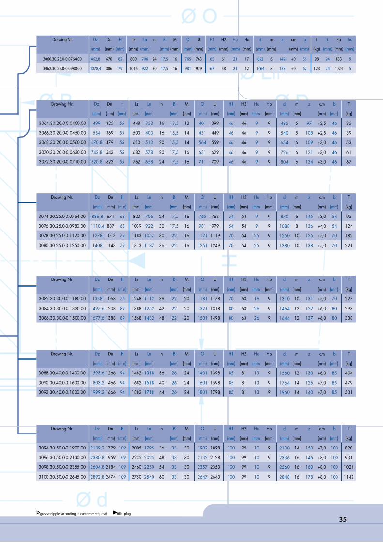
35grease nipple (according to customer request) filler plug
Drawing Nr.
3060.30.25.0-0.0764.00
3062.30.25.0-0.0980.00
Dz
(mm)
862,8
1078,4
Dn
(mm)
670
886
H
(mm)
82
79
Lz
(mm)
800
1015
Ln
(mm)
706
922
n
24
30
B
(mm)
17,5
17,5
M
(mm)
16
16
O
(mm)
765
981
U
(mm)
763
979
H1
(mm)
65
67
H2
(mm)
61
58
Hu
(mm)
21
21
Ho
(mm)
17
12
m
(mm)
6
8
z
142
133
x.m
(mm)
+0
+0
b
(mm)
56
62
T
(kg)
98
123
t
(mm)
24
24
d
(mm)
852
1064
Zu
(mm)
833
1024
hu
(mm)
9
5
Drawing Nr.
3064.30.20.0-0.0400.00
3066.30.20.0-0.0450.00
3068.30.20.0-0.0560.00
3070.30.20.0-0.0630.00
3072.30.20.0-0.0710.00
Dz
(mm)
499
554
670,8
742,8
820,8
Dn
(mm)
325
369
479
543
623
H
(mm)
55
55
55
55
55
Lz
(mm)
448
500
610
682
762
Ln
(mm)
352
400
510
578
658
n
16
16
20
20
24
B
(mm)
13,5
15,5
15,5
17,5
17,5
M
(mm)
12
14
14
16
16
O
(mm)
401
451
564
631
711
U
(mm)
399
449
559
629
709
H1
(mm)
46
46
46
46
46
H2
(mm)
46
46
46
46
46
Hu
(mm)
9
9
9
9
9
Ho
(mm)
9
9
9
9
9
m
(mm)
5
5
6
6
6
z
97
108
109
121
134
x.m
(mm)
+2,5
+2,5
+3,0
+3,0
+3,0
b
(mm)
46
46
46
46
46
T
(kg)
35
39
53
61
67
d
(mm)
485
540
654
726
804
Drawing Nr.
3074.30.25.0-0.0764.00
3076.30.25.0-0.0980.00
3078.30.25.0-0.1120.00
3080.30.25.0-0.1250.00
Dz
(mm)
886,8
1110,4
1278
1408
Dn
(mm)
671
887
1013
1143
H
(mm)
63
63
79
79
Lz
(mm)
823
1039
1183
1313
Ln
(mm)
706
922
1057
1187
n
24
30
30
36
B
(mm)
17,5
17,5
22
22
M
(mm)
16
16
16
16
O
(mm)
765
981
1121
1251
U
(mm)
763
979
1119
1249
H1
(mm)
54
54
70
70
H2
(mm)
54
54
54
54
Hu
(mm)
9
9
25
25
Ho
(mm)
9
9
9
9
m
(mm)
6
8
10
10
z
145
136
125
138
x.m
(mm)
+3,0
+4,0
+5,0
+5,0
b
(mm)
54
54
70
70
T
(kg)
95
124
182
221
d
(mm)
870
1088
1250
1380
Drawing Nr.
3082.30.30.0-0.1180.00
3084.30.30.0-0.1320.00
3086.30.30.0-0.1500.00
Dz
(mm)
1338
1497,6
1677,6
Dn
(mm)
1068
1208
1388
H
(mm)
76
89
89
Lz
(mm)
1248
1388
1568
Ln
(mm)
1112
1252
1432
n
36
42
48
B
(mm)
22
22
22
M
(mm)
20
20
20
O
(mm)
1181
1321
1501
U
(mm)
1178
1318
1498
H1
(mm)
70
80
80
H2
(mm)
63
63
63
Hu
(mm)
16
26
26
Ho
(mm)
9
9
9
m
(mm)
10
12
12
z
131
122
137
x.m
(mm)
+5,0
+6,0
+6,0
b
(mm)
70
80
80
T
(kg)
227
298
338
d
(mm)
1310
1464
1644
Drawing Nr.
3088.30.40.0-0.1400.00
3090.30.40.0-0.1600.00
3092.30.40.0-0.1800.00
Dz
(mm)
1593,6
1803,2
1999,2
Dn
(mm)
1266
1466
1666
H
(mm)
94
94
94
Lz
(mm)
1482
1682
1882
Ln
(mm)
1318
1518
1718
n
36
40
44
B
(mm)
26
26
26
M
(mm)
24
24
24
O
(mm)
1401
1601
1801
U
(mm)
1398
1598
1798
H1
(mm)
85
85
85
H2
(mm)
81
81
81
Hu
(mm)
13
13
13
Ho
(mm)
9
9
9
m
(mm)
12
14
14
z
130
126
140
x.m
(mm)
+6,0
+7,0
+7,0
b
(mm)
85
85
85
T
(kg)
404
479
531
d
(mm)
1560
1764
1960
Drawing Nr.
3094.30.50.0-0.1900.00
3096.30.50.0-0.2130.00
3098.30.50.0-0.2355.00
3100.30.50.0-0.2645.00
Dz
(mm)
2139,2
2380,8
2604,8
2892,8
Dn
(mm)
1729
1959
2184
2474
H
(mm)
109
109
109
109
Lz
(mm)
2005
2235
2460
2750
Ln
(mm)
1795
2025
2250
2540
n
36
48
54
60
B
(mm)
33
33
33
33
M
(mm)
30
30
30
30
O
(mm)
1902
2132
2357
2647
U
(mm)
1898
2128
2353
2643
H1
(mm)
100
100
100
100
H2
(mm)
99
99
99
99
Hu
(mm)
10
10
10
10
Ho
(mm)
9
9
9
9
m
(mm)
14
16
16
16
z
150
146
160
178
x.m
(mm)
+7,0
+8,0
+8,0
+8,0
b
(mm)
100
100
100
100
T
(kg)
820
931
1024
1142
d
(mm)
2100
2336
2560
2848
36
MMODEL 3000

37
Drawing Nr.
3102.20.25.0-0.0886.00
3104.20.25.0-0.1077.00
Dz
(mm)
980
1170
Dn
(mm)
784
960
H
(mm)
77
84
Lz
(mm)
944
1134
Ln
(mm)
850
1040
n
36
36
B
(mm)
17,5
17,5
M
(mm)
16
16
O
(mm)
885
1076
U
(mm)
887
1078
H1
(mm)
67
66
H2
(mm)
56
64
Hu
(mm)
21
20
Ho
(mm)
10
18
m
(mm)
8
10
z
100
98
x.m
(mm)
-0
-0
b
(mm)
62
61
T
(kg)
109
148
t
(mm)
24
24
d
(mm)
800
980
Zu
(mm)
820
1010
hu
(mm)
5
5
grease nipple (according to customer request) filler plug
Drawing Nr.
3130.20.40.0-0.1500.00
3132.20.40.0-0.1700.00
Dz
(mm)
1634
1834
Dn
(mm)
1308
1498
H
(mm)
94
94
Lz
(mm)
1582
1782
Ln
(mm)
1418
1618
n
40
44
B
(mm)
26
26
M
(mm)
24
24
O
(mm)
1498
1698
U
(mm)
1501
1701
H1
(mm)
85
85
H2
(mm)
81
81
Hu
(mm)
13
13
Ho
(mm)
9
9
m
(mm)
12
14
z
110
108
x.m
(mm)
-6,0
-7,0
b
(mm)
85
85
T
(kg)
410
475
d
(mm)
1320
1512
Drawing Nr.
3134.20.50.0-0.1800.00
3136.20.50.0-0.2000.00
3138.20.50.0-0.2240.00
3140.20.50.0-0.2490.00
3142.20.50.0-0.2800.00
Dz
(mm)
1971
2171
2411
2661
2971
Dn
(mm)
1554
1764
1984
2240
2544
H
(mm)
109
109
109
109
109
Lz
(mm)
1905
2105
2345
2595
2905
Ln
(mm)
1695
1895
2135
2385
2695
n
36
40
48
54
60
B
(mm)
33
33
33
33
33
M
(mm)
30
30
30
30
30
O
(mm)
1798
1998
2238
2488
2798
U
(mm)
1802
2002
2242
2492
2802
H1
(mm)
100
100
100
100
100
H2
(mm)
99
99
99
99
99
Hu
(mm)
10
10
10
10
10
Ho
(mm)
9
9
9
9
9
m
(mm)
14
14
16
16
16
z
112
127
125
141
160
x.m
(mm)
-7,0
-7,0
-8,0
-8,0
-8,0
b
(mm)
100
100
100
100
100
T
(kg)
762
827
961
1053
1205
d
(mm)
1568
1778
2000
2256
2560
Drawing Nr.
3106.20.20.0-0.0400.00
3108.20.20.0-0.0450.00
3110.20.20.0-0.0560.00
3112.20.20.0-0.0630.00
3114.20.20.0-0.0710.00
Dz
(mm)
475
531
641
717
797
Dn
(mm)
300
345
450
516
594
H
(mm)
55
55
55
55
55
Lz
(mm)
448
500
610
682
762
Ln
(mm)
352
400
510
578
658
n
16
16
20
20
24
B
(mm)
13,5
15,5
15,5
17,5
17,5
M
(mm)
12
14
14
16
16
O
(mm)
399
449
559
629
709
U
(mm)
401
451
561
631
711
H1
(mm)
46
46
46
46
46
H2
(mm)
46
46
46
46
46
Hu
(mm)
9
9
9
9
9
Ho
(mm)
9
9
9
9
9
m
(mm)
5
5
6
6
6
z
61
70
76
87
100
x.m
(mm)
-2,5
-2,5
-3,0
-3,0
-3,0
b
(mm)
46
46
46
46
46
T
(kg)
33
38
51
59
68
d
(mm)
305
350
456
522
600
Drawing Nr.
3116.20.25.0-0.0886.00
3118.20.25.0-0.1077.00
3120.20.25.0-0.1180.00
Dz
(mm)
980
1169
1287
Dn
(mm)
752
930
1020
H
(mm)
63
63
63
Lz
(mm)
944
1134
1243
Ln
(mm)
827
1017
1117
n
36
36
36
B
(mm)
17,5
17,5
22
M
(mm)
16
16
20
O
(mm)
885
1076
1179
U
(mm)
887
1078
1181
H1
(mm)
54
54
60
H2
(mm)
54
54
54
Hu
(mm)
9
9
15
Ho
(mm)
9
9
9
m
(mm)
8
10
10
z
95
94
103
x.m
(mm)
-4,0
-5,0
-5,0
b
(mm)
54
54
54
T
(kg)
111
140
185
d
(mm)
760
940
1030
Drawing Nr.
3122.20.30.0-0.1120.00
3124.20.30.0-0.1250.00
3126.20.30.0-0.1400.00
3128.20.30.0-0.1600.00
Dz
(mm)
1232
1362
1512
1712
Dn
(mm)
960
1090
1224
1428
H
(mm)
79
79
89
89
Lz
(mm)
1188
1318
1468
1668
Ln
(mm)
1052
1182
1332
1532
n
36
40
44
48
B
(mm)
22
22
22
22
M
(mm)
20
20
20
20
O
(mm)
1118
1248
1398
1598
U
(mm)
1121
1251
1401
1601
H1
(mm)
70
70
80
80
H2
(mm)
63
63
63
63
Hu
(mm)
16
16
26
26
Ho
(mm)
9
9
9
9
m
(mm)
10
10
12
12
z
97
110
103
120
x.m
(mm)
-5,0
-5,0
-5,0
-5,0
b
(mm)
70
70
80
80
T
(kg)
206
231
296
334
d
(mm)
970
1100
1236
1440

38
MMODEL 4000
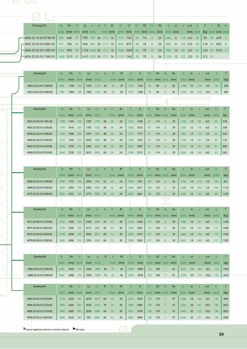
39
Drawing Nr.
4072.20.40.0-0.2199.00
4074.20.40.0-0.2622.00
4076.20.40.0-0.2950.00
4078.20.40.0-0.3300.00
Dz
(mm)
2350
2770
3100
3450
Dn
(mm)
1920
2336
2646
3006
H
(mm)
156
156
156
156
Lz
(mm)
2295
2715
3045
3395
Ln
(mm)
2065
2485
2815
3165
n
52
60
60
66
B
(mm)
33
33
33
33
M
(mm)
30
30
30
30
O
(mm)
2168
2590
2918
3268
U
(mm)
2164
2587
2915
3265
H1
(mm)
117
117
117
117
H2
(mm)
150
150
150
150
Hu
(mm)
6
6
6
6
Ho
(mm)
39
39
39
39
m
(mm)
16
16
18
18
z
121
147
148
168
x.m
(mm)
-8,0
-8,0
-9,0
-9,0
b
(mm)
117
117
117
117
T
(kg)
1238
1495
1764
1935
d
(mm)
1936
2352
2664
3024
Drawing Nr.
4066.20.35.0-0.1960.00
4068.20.35.0-0.2500.00
4070.20.35.0-0.2690.00
Dz
(mm)
2090
2630
2820
Dn
(mm)
1722
2254
2432
H
(mm)
138
138
138
Lz
(mm)
2045
2585
2775
Ln
(mm)
1850
2385
2580
n
52
66
72
B
(mm)
26
26
26
M
(mm)
24
24
24
O
(mm)
1926
2466
2656
U
(mm)
1931
2471
2661
H1
(mm)
104
104
104
H2
(mm)
132
132
132
Hu
(mm)
6
6
6
Ho
(mm)
34
34
34
m
(mm)
14
14
16
z
124
162
153
x.m
(mm)
-7,0
-7,0
-8,0
b
(mm)
104
104
104
T
(kg)
851
1112
1225
d
(mm)
1736
2268
2448
Drawing Nr.
4054.20.30.0-0.1381.00
4056.20.30.0-0.1630.00
4058.20.30.0-0.1800.00
4060.20.30.0-0.1995.00
4062.20.30.0-0.2330.00
4064.20.30.0-0.2538.00
Dz
(mm)
1500
1750
1920
2115
2450
2660
Dn
(mm)
1164
1416
1568
1764
2100
2228
H
(mm)
120
120
120
120
120
120
Lz
(mm)
1455
1705
1875
2070
2405
2615
Ln
(mm)
1275
1525
1695
1890
2225
2430
n
36
40
48
48
54
60
B
(mm)
26
26
26
26
26
26
M
(mm)
24
24
24
24
24
24
O
(mm)
1352
1602
1771
1966
2301
2509
U
(mm)
1358
1610
1777
1972
2307
2515
H1
(mm)
91
91
91
91
91
91
H2
(mm)
114
114
114
114
114
114
Hu
(mm)
6
6
6
6
6
6
Ho
(mm)
29
29
29
29
29
29
m
(mm)
12
12
14
14
14
16
z
98
119
113
127
151
144
x.m
(mm)
-6,0
-6,0
-7,0
-7,0
-7,0
-8,0
b
(mm)
91
91
91
91
91
91
T
(kg)
474
558
643
716
839
963
d
(mm)
1176
1428
1582
1778
2114
2304
Drawing Nr.
4050.20.25.0-0.1360.00
4052.20.25.0-0.1600.00
Dz
(mm)
1460
1700
Dn
(mm)
1180
1404
H
(mm)
102
102
Lz
(mm)
1425
1665
Ln
(mm)
1270
1510
n
36
42
B
(mm)
22
22
M
(mm)
20
20
O
(mm)
1337
1577
U
(mm)
1342
1582
m
(mm)
10
12
d
(mm)
1190
1416
H1
(mm)
76
76
H2
(mm)
96
96
Hu
(mm)
6
6
Ho
(mm)
26
26
x.m
(mm)
-5,0
-6,0
z
119
118
T
(kg)
336
405
b
(mm)
76
76
Drawing Nr.
4000.20.18.0-0.0748.00
4002.20.20.0-0.0895.00
4004.20.20.0-0.1085.00
4006.20.20.0-0.1360.00
Dz
(mm)
823
971
1161
1440
Dn
(mm)
648
784
960
1210
H
(mm)
77
82
90
82
Lz
(mm)
798
944
1134
1410
Ln
(mm)
705
850
1040
1300
n
24
30
36
54
B
(mm)
17,5
17,5
17,5
17,5
M
(mm)
16
16
16
16
O
(mm)
710
854
1044
1319
U
(mm)
734
879
1069
1342
H1
(mm)
54
58
66
58
H2
(mm)
74
78
78
78
Hu
(mm)
3
4
12
4
Ho
(mm)
23
24
24
24
m
(mm)
6
8
10
10
z
110
100
98
122
x.m
(mm)
-0,0
-0,0
-0,0
-5,0
b
(mm)
45
50
55
58
T
(kg)
90
118
154
213
t
(mm)
30
35
35
35
d
(mm)
660
800
980
1220
Zn
(mm)
678
820
1010
-
hu
(mm)
9
8
11
-
grease nipple (according to customer request) filler plug
Drawing Nr.
4082.20.50.0-0.2559.00
4084.20.50.0-0.3520.00
4086.20.50.0-0.3739.00
4090.20.50.0-0.3839.00
Dz
(mm)
2725
3685
3905
4005
H
(mm)
185
185
185
185
Lz
(mm)
2670
3630
3850
395
Ln
(mm)
2410
3370
3590
3690
N
60
78
84
84
B
(mm)
33
33
33
33
M
(mm)
30
30
30
30
O
(mm)
2522
3482
3701
3801
U
(mm)
2524
3485
3704
3804
H1
(mm)
138
138
138
138
H2
(mm)
178
178
178
178
Hu
(mm)
7
7
7
7
Ho
(mm)
47
47
47
47
m
(mm)
18
20
20
20
z
126
161
172
177
x.m
(mm)
-9,0
-10,0
-10,0
-10,0
b
(mm)
138
138
138
138
T
(kg)
1892
2657
2823
2905
d
(mm)
2268
3220
3440
3540
Dn
(mm)
2250
3200
3420
3520
Drawing Nr.
4080.20.45.0-0.2940.00
4088.20.45.0-0.3400.00
Dz
(mm)
3100
3560
Dn
(mm)
2656
3080
H
(mm)
175
175
Lz
(mm)
3045
3505
Ln
(mm)
2800
3260
N
66
72
B
(mm)
33
33
M
(mm)
30
30
O
(mm)
2903
3363
U
(mm)
2900
3358
m
(mm)
16
20
d
(mm)
2672
3100
H1
(mm)
132
132
H2
(mm)
168
168
Hu
(mm)
7
7
Ho
(mm)
43
43
x.m
(mm)
-8,0
-10,0
z
167
155
T
(kg)
1950
2435
b
(mm)
132
132

40
MMODEL 4000

41
Drawing Nr.
4008.30.20.0-0.0755.00
4010.30.20.0-0.0971.00
4012.30.20.0-0.1220.00
4014.30.20.0-0.1385.00
Dz
(mm)
862,8
1078,4
1342,4
1502,4
Dn
(mm)
679
895
1140
1305
H
(mm)
82
82
82
82
Lz
(mm)
800
1015
1270
1435
Ln
(mm)
706
922
1170
1335
n
24
30
48
54
B
(mm)
17,5
17,5
17,5
17,5
M
(mm)
16
16
16
16
O
(mm)
797
1012
1261
1426
U
(mm)
771
987
1238
1403
H1
(mm)
58
58
58
58
H2
(mm)
78
78
78
78
Hu
(mm)
4
4
4
4
Ho
(mm)
24
24
24
24
m
(mm)
6
8
8
8
z
142
133
165
185
x.m
(mm)
+0,0
+0,0
+4,0
+4,0
b
(mm)
50
50
58
58
T
(kg)
101
128
178
201
t
(mm)
35
35
35
35
d
(mm)
852
1064
1320
1480
Zz
(mm)
833
1024
-
-
Hu
(mm)
8
8
-
-
Drawing Nr.
4022.30.30.0-0.1440.00
4024.30.30.0-0.1734.00
4026.30.30.0-0.2031.00
4028.30.30.0-0.2235.00
Dz
(mm)
1653,6
1953,6
2253,6
2457,6
Dn
(mm)
1320
1615
1910
2115
H
(mm)
120
120
120
120
Lz
(mm)
1545
1845
2140
2345
Ln
(mm)
1365
1660
1955
2160
N
36
44
48
52
B
(mm)
26
26
26
26
M
(mm)
24
24
24
24
O
(mm)
1469
1763
2060
2264
U
(mm)
1460
1757
2054
2258
H1
(mm)
91
91
91
91
H2
(mm)
114
114
114
114
Hu
(mm)
6
6
6
6
Ho
(mm)
29
29
29
29
m
(mm)
12
12
12
12
z
135
160
185
202
x.m
(mm)
+6,0
+6,0
+6,0
+6,0
b
(mm)
91
91
91
91
T
(kg)
520
636
755
827
d
(mm)
1620
1920
2220
2424
Drawing Nr.
4016.30.25.0-0.1200.00
4018.30.25.0-0.1461.00
4020.30.25.0-0.1800.00
Dz
(mm)
1378
1648
2001,6
Dn
(mm)
1100
1360
1700
H
(mm)
102
102
102
Lz
(mm)
1290
1555
1890
Ln
(mm)
1135
1395
1735
n
36
40
48
B
(mm)
22
22
22
M
(mm)
20
20
20
O
(mm)
1223
1484
1823
U
(mm)
1215
1479
1818
H1
(mm)
76
76
76
H2
(mm)
96
96
96
Hu
(mm)
6
6
6
Ho
(mm)
26
26
26
m
(mm)
10
10
12
z
135
162
164
x.m
(mm)
+5,0
+5,0
+6,0
b
(mm)
76
76
76
T
(kg)
301
381
488
d
(mm)
1350
1620
1968
Drawing Nr.
4030.30.35.0-0.1750.00
4032.30.35.0-0.1220.00
4034.30.35.0-0.2620.00
Dz
(mm)
1985,2
2461,2
2876,8
Dn
(mm)
1620
2090
2490
H
(mm)
138
138
138
Lz
(mm)
1860
2335
2735
Ln
(mm)
1670
2135
2540
N
44
60
60
B
(mm)
26
26
26
M
(mm)
24
24
24
O
(mm)
1784
2254
2654
U
(mm)
1779
2249
2649
H1
(mm)
104
104
104
H2
(mm)
132
132
132
Hu
(mm)
6
6
6
Ho
(mm)
34
34
34
m
(mm)
14
14
16
z
139
173
177
x.m
(mm)
+7,0
+7,0
+8,0
b
(mm)
104
104
104
T
(kg)
789
1019
1244
d
(mm)
1946
2422
2832
Drawing Nr.
4036.30.40.0-0.2240.00
4038.30.40.0-0.2619.00
4040.30.40.0-0.2795.00
4042.30.40.0-0.2915.00
4044.30.40.0-0.3150.00
Dz
(mm)
2524,8
2912,4
3096,0
3216,0
3456,0
Dn
(mm)
2090
2465
2645
2765
3000
H
(mm)
156
156
156
156
156
Lz
(mm)
2375
2755
2930
3050
3285
Ln
(mm)
2145
2520
2700
2820
3055
N
48
52
54
60
60
B
(mm)
33
33
33
33
33
M
(mm)
30
30
30
30
30
O
(mm)
2272
2651
2827
2947
3182
U
(mm)
2275
2654
2830
2950
3185
H1
(mm)
117
117
117
117
117
H2
(mm)
150
150
150
150
150
Hu
(mm)
6
6
6
6
6
Ho
(mm)
39
39
39
39
39
m
(mm)
16
18
20
20
20
z
155
159
152
158
170
x.m
(mm)
+8
+9
+10
+10
+10
b
(mm)
117
117
117
117
117
T
(kg)
1316
1615
1723
1790
1969
d
(mm)
2480
2862
3040
3160
3400
grease nipple (according to customer request) filler plug
Drawing Nr.
4046.30.50.0-0.2987.00
4048.30.50.0-0.3167.00
4102.30.50.0-0.3347.00
4104.30.50.0-0.3567.00
4106.30.50.0-0.3747.00
4108.30.50.0-0.4140.00
Dz
(mm)
3290,4
3470,4
3650,4
3866,4
4046,4
4456,0
Dn
(mm)
2820
3000
3180
3400
3580
3970
H
(mm)
185
185
185
185
185
187
Lz
(mm)
3130
3310
3490
3710
3890
4285
Ln
(mm)
2880
3060
3240
3460
3640
4030
N
66
66
72
78
84
90
B
(mm)
33
33
33
33
33
33
M
(mm)
30
30
30
30
30
30
O
(mm)
3025
3205
3385
3605
3785
4178
U
(mm)
3022
3202
3382
3602
3782
4175
H1
(mm)
138
138
138
138
138
140
H2
(mm)
178
178
178
178
178
178
Hu
(mm)
7
7
7
7
7
9
Ho
(mm)
47
47
47
47
47
47
m
(mm)
18
18
18
18
18
20
z
180
190
200
212
222
220
x.m
(mm)
+9
+9
+9
+9
+9
+10
b
(mm)
138
138
138
138
138
140
T
(kg)
2288
2431
2566
2702
2837
3282
d
(mm)
3240
3420
3600
3816
3996
4400

42
MMODEL 4000

43grease nipple (according to customer request) filler plug
Drawing Nr.
4802.20.22.0-0.0625.00
4804.20.22.0-0.0897.00
4806.20.22.0-0.1087.00
4808.20.25.0-0.1100.00
4810.20.30.0-0.1220.00
4812.20.30.0-0.1347.00
4814.20.30.0-0.1385.00
4816.20.30.0-0.1615.00
4818.20.30.0-0.2003.00
Dz
(mm)
705
973
1172
1200
1345
1470
1530
1750
2178
Dn
(mm)
504
786
962
963,5
1061,6
1183
1186
1418,4
1776
H
(mm)
92
97
97
110
108
108
144
120
144
Lz
(mm)
675
944
1134
1160
1290
1425
1480
1705
2108
Ln
(mm)
575
850
1040
1040
1150
1270
1290
1525
1898
n
32
36
36
36
40
40
48
40
72
B
(mm)
18
18
18
22
22
22
26
26
30
M
(mm)
16
16
16
20
20
22
24
24
27
O
(mm)
627
899
1089
1102
1222
1350
1388
1618
2005
U
(mm)
623
895
1085
1098
1218
1344
1382
1612
2000
H1
(mm)
83
88
88
96
98
98
134
110
134
H2
(mm)
83
88
88
96
98
98
134
105
134
Hu
(mm)
9
9
9
14
10
10
10
10
10
Ho
(mm)
9
9
9
14
10
10
10
15
10
m
(mm)
8
8
10
10
10
10
10
12
12
z
65
100
98
98
108
120
120
120
150
x.m
(mm)
0
0
0
0
0
0
0
0
0
b
(mm)
83
88
88
96
98
98
134
110
134
T
(kg)
95
141
193
239
331
371
612
572
1062
d
(mm)
520
800
980
980
1080
1200
1200
1200
1800
Drawing Nr.
4850.30.25.0-0.0383.00
4852.30.22.0-0.0475.00
4854.30.25.0-0.0574.00
4856.30.20.0-0.0753.00
4858.30.30.0-0.0823.00
4860.30.20.0-0.0968.00
4862.30.25.0-0.1074.00
4864.30.30.0-0.1117.00
4866.30.30.0-0.1213.00
4868.30.40.0-0.1390.00
Dz
(mm)
504
595
712
864
979
1080
1200
1289,5
1380
1634
Dn
(mm)
300
382
470
678
718
893
976
985
1095
1208
H
(mm)
92
98
98
92
102
92
98
108
108
148
Lz
(mm)
436
540
640
800
893
1015
1135
1198
1290
1500
Ln
(mm)
330
410
508
706
753
922
1012
1035
1135
1280
n
16
24
24
36
36
30
36
40
48
48
B
(mm)
18
18
18
18
22
18
20
22
24
33
M
(mm)
16
16
16
16
20
16
18
20
22
30
O
(mm)
381
473
572
751
821
966
1072
1114
1210
1387
U
(mm)
384
477
576
755
825
970
1076
1120
1216
1393
H1
(mm)
83
88
88
83
92
83
88
98
98
138
H2
(mm)
83
88
88
83
92
83
88
98
98
134
Hu
(mm)
9
10
10
9
10
9
10
10
10
10
Ho
(mm)
9
10
10
9
10
9
10
10
10
14
m
(mm)
8
5
8
6
10
8
8
10
10
14
z
61
117
87
142
94
133
148
125
136
113
x.m
(mm)
0
0
0
0
0
0
0
0
0
0
b
(mm)
83
88
88
83
92
83
88
98
98
138
T
(kg)
64
85
123
114
197
148
210
332
325
797
d
(mm)
488
585
696
852
940
1064
1184
1250
1360
1582
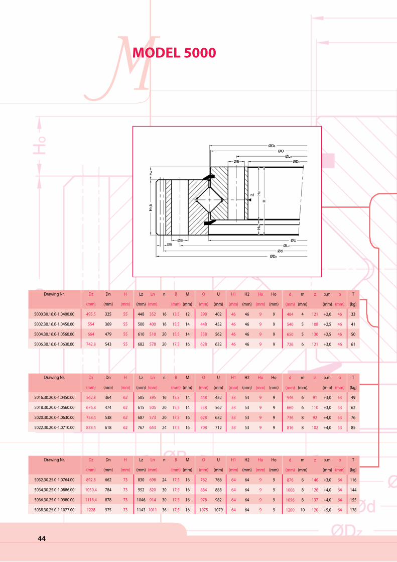
44
MMODEL 5000
Drawing Nr.
5016.30.20.0-1.0450.00
5018.30.20.0-1.0560.00
5020.30.20.0-1.0630.00
5022.30.20.0-1.0710.00
Dz
(mm)
562,8
676,8
758,4
838,4
Dn
(mm)
364
474
538
618
H
(mm)
62
62
62
62
Lz
(mm)
505
615
687
767
Ln
(mm)
395
505
573
653
n
16
20
20
24
B
(mm)
15,5
15,5
17,5
17,5
M
(mm)
14
14
16
16
O
(mm)
448
558
628
708
U
(mm)
452
562
632
712
H1
(mm)
53
53
53
53
H2
(mm)
53
53
53
53
Hu
(mm)
9
9
9
9
Ho
(mm)
9
9
9
9
m
(mm)
6
6
8
8
z
91
110
92
102
x.m
(mm)
+3,0
+3,0
+4,0
+4,0
b
(mm)
53
53
53
53
T
(kg)
49
62
76
85
d
(mm)
546
660
736
816
Drawing Nr.
5000.30.16.0-1.0400.00
5002.30.16.0-1.0450.00
5004.30.16.0-1.0560.00
5006.30.16.0-1.0630.00
Dz
(mm)
495,5
554
664
742,8
Dn
(mm)
325
369
479
543
H
(mm)
55
55
55
55
Lz
(mm)
448
500
610
682
Ln
(mm)
352
400
510
578
n
16
16
20
20
B
(mm)
13,5
15,5
15,5
17,5
M
(mm)
12
14
14
16
O
(mm)
398
448
558
628
U
(mm)
402
452
562
632
H1
(mm)
46
46
46
46
H2
(mm)
46
46
46
46
Hu
(mm)
9
9
9
9
Ho
(mm)
9
9
9
9
m
(mm)
4
5
5
6
z
121
108
130
121
x.m
(mm)
+2,0
+2,5
+2,5
+3,0
b
(mm)
46
46
46
46
T
(kg)
33
41
50
61
d
(mm)
484
540
650
726
Drawing Nr.
5032.30.25.0-1.0764.00
5034.30.25.0-1.0886.00
5036.30.25.0-1.0980.00
5038.30.25.0-1.1077.00
Dz
(mm)
892,8
1030,4
1118,4
1228
Dn
(mm)
662
784
878
975
H
(mm)
73
73
73
73
Lz
(mm)
830
952
1046
1143
Ln
(mm)
698
820
914
1011
n
24
30
30
36
B
(mm)
17,5
17,5
17,5
17,5
M
(mm)
16
16
16
16
O
(mm)
762
884
978
1075
U
(mm)
766
888
982
1079
H1
(mm)
64
64
64
64
H2
(mm)
64
64
64
64
Hu
(mm)
9
9
9
9
Ho
(mm)
9
9
9
9
m
(mm)
6
8
8
10
z
146
126
137
120
x.m
(mm)
+3,0
+4,0
+4,0
+5,0
b
(mm)
64
64
64
64
T
(kg)
116
144
155
178
d
(mm)
876
1008
1096
1200

45
Drawing Nr.
5080.30.36.0-1.1700.00
5082.30.36.0-1.1800.00
5084.30.36.0-1.1900.00
5086.30.36.0-1.2000.00
Dz
(mm)
1943,2
2041,2
2139,2
2237,2
Dn
(mm)
1529
1629
1729
1829
H
(mm)
100
100
100
100
Lz
(mm)
1805
1905
2005
2105
Ln
(mm)
1595
1695
1795
1895
n
32
36
36
40
B
(mm)
33
33
33
33
M
(mm)
30
30
30
30
O
(mm)
1698
1798
1898
1998
U
(mm)
1702
1802
1902
2002
H1
(mm)
90
90
90
90
H2
(mm)
90
90
90
90
Hu
(mm)
10
10
10
10
Ho
(mm)
10
10
10
10
m
(mm)
14
14
14
14
z
136
143
150
157
x.m
(mm)
+7,0
+7,0
+7,0
+7,0
b
(mm)
90
90
90
90
T
(kg)
653
685
721
749
d
(mm)
1904
2002
2100
2198
Drawing Nr.
5064.30.28.0-1.1400.00
5066.30.28.0-1.1500.00
5068.30.28.0-1.1600.00
5070.30.28.0-1.1700.00
Dz
(mm)
1593,6
1689,6
1803,2
1915,2
Dn
(mm)
1266
1366
1466
1566
H
(mm)
80
80
80
80
Lz
(mm)
1482
1582
1682
1782
Ln
(mm)
1318
1418
1518
1618
n
36
40
40
44
B
(mm)
26
26
26
26
M
(mm)
24
24
24
24
O
(mm)
1398
1498
1598
1698
U
(mm)
1402
1502
1602
1702
H1
(mm)
71
71
71
71
H2
(mm)
71
71
71
71
Hu
(mm)
9
9
9
9
Ho
(mm)
9
9
9
9
m
(mm)
12
12
14
14
z
130
138
126
134
x.m
(mm)
+6,0
+6,0
+7,0
+7,0
b
(mm)
71
71
71
71
T
(kg)
332
349
388
431
d
(mm)
1560
1656
1764
1876
Drawing Nr.
5048.30.25.0-1.1120.00
5050.30.25.0-1.1180.00
5052.30.25.0-1.1250.00
5054.30.25.0-1.1320.00
Dz
(mm)
1278
1338
1408
1497,6
Dn
(mm)
1008
1068
1138
1208
H
(mm)
73
73
73
73
Lz
(mm)
1188
1248
1318
1388
Ln
(mm)
1052
1112
1182
1252
n
36
36
40
42
B
(mm)
22
22
22
22
M
(mm)
20
20
20
20
O
(mm)
1118
1178
1248
1318
U
(mm)
1122
1182
1252
1322
H1
(mm)
64
64
64
64
H2
(mm)
64
64
64
64
Hu
(mm)
9
9
9
9
Ho
(mm)
9
9
9
9
m
(mm)
10
10
10
12
z
125
131
138
122
x.m
(mm)
+5,0
+5,0
+5,0
+6,0
b
(mm)
64
64
64
64
T
(kg)
195
206
216
247
d
(mm)
1250
1310
1380
1464
Drawing Nr.
5096.30.40.0-1.2000.00
5098.30.40.0-1.2128.00
5100.30.40.0-1.2240.00
5102.30.40.0-1.2368.00
Dz
(mm)
2252,8
2380,8
2492,8
2620,8
Dn
(mm)
1824
1952
2064
2192
H
(mm)
108
108
108
108
Lz
(mm)
2110
2238
2350
2478
Ln
(mm)
1890
2018
2130
2258
n
42
48
48
56
B
(mm)
33
33
33
33
M
(mm)
30
30
30
30
O
(mm)
1997
2125
2237
2365
U
(mm)
2003
2131
2243
2371
H1
(mm)
98
98
98
98
H2
(mm)
98
98
98
98
Hu
(mm)
10
10
10
10
Ho
(mm)
10
10
10
10
m
(mm)
16
16
16
16
z
138
146
153
161
x.m
(mm)
+8,0
+8,0
+8,0
+8,0
b
(mm)
98
98
98
98
T
(kg)
848
896
946
993
d
(mm)
2208
2336
2448
2576
Drawing Nr.
5128.30.50.0-1.2500.00
5130.30.50.0-1.2660.00
5132.30.50.0-1.2800.00
5134.30.50.0-1.3000.00
Dz
(mm)
2796
2956
3096
3296
Dn
(mm)
2309
2469
2609
2809
H
(mm)
130
130
130
130
Lz
(mm)
2625
2785
2925
3125
Ln
(mm)
2375
2535
2675
2875
n
60
64
72
76
B
(mm)
33
33
33
33
M
(mm)
30
30
30
30
O
(mm)
2497
2657
2797
2997
U
(mm)
2503
2663
2803
3003
H1
(mm)
120
120
120
120
H2
(mm)
120
120
120
120
Hu
(mm)
10
10
10
10
Ho
(mm)
10
10
10
10
m
(mm)
20
20
20
20
z
137
145
152
162
x.m
(mm)
+10,0
+10,0
+10,0
+10,0
b
(mm)
120
120
120
120
T
(kg)
1453
1544
1616
1733
d
(mm)
2740
2900
3040
3240
Drawing Nr.
5112.30.45.0-1.2240.00
5114.30.45.0-1.2366.00
5116.30.45.0-1.2510.00
5118.30.45.0-1.2654.00
Dz
(mm)
2516,4
2642,4
2786,4
2930,4
Dn
(mm)
2057
2183
2327
2471
H
(mm)
119
119
119
119
Lz
(mm)
2357
2483
2627
2771
Ln
(mm)
2123
2249
2393
2537
n
48
52
56
60
B
(mm)
33
33
33
33
M
(mm)
30
30
30
30
O
(mm)
2237
2363
2507
2651
U
(mm)
2243
2369
2513
2657
H1
(mm)
109
109
109
109
H2
(mm)
109
109
109
109
Hu
(mm)
10
10
10
10
Ho
(mm)
10
10
10
10
m
(mm)
18
18
18
18
z
137
144
152
160
x.m
(mm)
+9,0
+9,0
+9,0
+9,0
b
(mm)
109
109
109
109
T
(kg)
1122
1182
1258
1329
d
(mm)
2466
2592
2736
2880
grease nipple (according to customer request) filler plug

46
Drawing Nr.
5040.20.25.0-1.0764.00
5042.20.25.0-1.0886.00
5044.20.25.0-1.0980.00
5046.20.25.0-1.1077.00
Dz
(mm)
866
988
1082
1179
Dn
(mm)
636
744
840
920
H
(mm)
73
73
73
73
Lz
(mm)
830
952
1046
1143
Ln
(mm)
698
820
914
1011
n
24
30
30
36
B
(mm)
17,5
17,5
17,5
17,5
M
(mm)
16
16
16
16
O
(mm)
766
888
982
1079
U
(mm)
762
884
978
1075
H1
(mm)
64
64
64
64
H2
(mm)
64
64
64
64
Hu
(mm)
9
9
9
9
Ho
(mm)
9
9
9
9
m
(mm)
6
8
8
10
z
107
94
106
93
x.m
(mm)
-3,0
-4,0
-4,0
-5,0
b
(mm)
64
64
64
64
T
(kg)
113
138
152
177
d
(mm)
642
752
848
930
Drawing Nr.
5024.20.20.0-1.0450.00
5026.20.20.0-1.0560.00
5028.20.20.0-1.0630.00
5030.20.20.0-1.0710.00
Dz
(mm)
536
646
722
802
Dn
(mm)
336
444
496
576
H
(mm)
62
62
62
62
Lz
(mm)
505
615
687
767
Ln
(mm)
395
505
573
653
n
16
20
20
24
B
(mm)
15,5
15,5
17,5
17,5
M
(mm)
14
14
16
16
O
(mm)
452
562
632
712
U
(mm)
448
558
628
708
H1
(mm)
53
53
53
53
H2
(mm)
53
53
53
53
Hu
(mm)
9
9
9
9
Ho
(mm)
9
9
9
9
m
(mm)
6
6
8
8
z
57
75
63
73
x.m
(mm)
-3,0
-3,0
-4,0
-4,0
b
(mm)
53
53
53
53
T
(kg)
48
60
75
84
d
(mm)
342
450
504
584
Drawing Nr.
5008.20.16.0-1.0400.00
5010.20.16.0-1.0450.00
5012.20.16.0-1.0560.00
5014.20.16.0-1.0630.00
Dz
(mm)
475
531
641
717
Dn
(mm)
304
345
455
516
H
(mm)
55
55
55
55
Lz
(mm)
448
500
610
682
Ln
(mm)
352
400
510
578
n
16
16
20
20
B
(mm)
13,5
15,5
15,5
17,5
M
(mm)
12
14
14
16
O
(mm)
402
452
562
632
U
(mm)
398
448
558
628
H1
(mm)
46
46
46
46
H2
(mm)
46
46
46
46
Hu
(mm)
9
9
9
9
Ho
(mm)
9
9
9
9
m
(mm)
4
5
5
6
z
77
70
92
87
x.m
(mm)
-2,0
-2,5
-2,5
-3,0
b
(mm)
46
46
46
46
T
(kg)
31
40
49
59
d
(mm)
308
350
460
522
MMODEL 5000

47
Drawing Nr.
5056.20.25.0-1.1120.00
5058.20.25.0-1.1180.00
5060.20.25.0-1.1250.00
5062.20.25.0-1.1320.00
Dz
(mm)
1232
1292
1362
1432
Dn
(mm)
960
1020
1090
1140
H
(mm)
73
73
73
73
Lz
(mm)
1188
1248
1318
1388
Ln
(mm)
1052
1112
1182
1252
n
36
36
40
40
B
(mm)
22
22
22
22
M
(mm)
20
20
20
20
O
(mm)
1122
1182
1252
1322
U
(mm)
1118
1178
1248
1318
H1
(mm)
64
64
64
64
H2
(mm)
64
64
64
64
Hu
(mm)
9
9
9
9
Ho
(mm)
9
9
9
9
m
(mm)
10
10
10
12
z
97
103
110
96
x.m
(mm)
-5,0
-5,0
-5,0
-6,0
b
(mm)
64
64
64
64
T
(kg)
192
202
213
240
d
(mm)
970
1030
1100
1152
Drawing Nr.
5104.20.40.0-1.2000.00
5106.20.40.0-1.2128.00
5108.20.40.0-1.2240.00
5110.20.40.0-1.2368.00
Dz
(mm)
2176
2304
2416
2544
Dn
(mm)
1744
1872
1984
2112
H
(mm)
108
108
108
108
Lz
(mm)
2110
2238
2350
2478
Ln
(mm)
1890
2018
2130
2258
n
42
48
48
56
B
(mm)
33
33
33
33
M
(mm)
30
30
30
30
O
(mm)
2003
2113
2243
2371
U
(mm)
1997
2125
2237
2365
H1
(mm)
98
98
98
98
H2
(mm)
98
98
98
98
Hu
(mm)
10
10
10
10
Ho
(mm)
10
10
10
10
m
(mm)
16
16
16
16
z
110
118
125
133
x.m
(mm)
-8,0
-8,0
-8,0
-8,0
b
(mm)
98
98
98
98
T
(kg)
832
882
932
980
d
(mm)
1760
1888
2000
2128
Drawing Nr.
5088.20.36.0-1.1700.00
5090.20.36.0-1.1800.00
5092.20.36.0-1.1900.00
5094.20.36.0-1.2000.00
Dz
(mm)
1871
1971
2071
2171
Dn
(mm)
1456
1554
1652
1764
H
(mm)
100
100
100
100
Lz
(mm)
1805
1905
2005
2105
Ln
(mm)
1595
1695
1795
1895
n
32
36
36
40
B
(mm)
33
33
33
33
M
(mm)
30
30
30
30
O
(mm)
1702
1802
1902
2002
U
(mm)
1698
1798
1898
1998
H1
(mm)
90
90
90
90
H2
(mm)
90
90
90
90
Hu
(mm)
10
10
10
10
Ho
(mm)
10
10
10
10
m
(mm)
14
14
14
14
z
105
112
119
127
x.m
(mm)
-7,0
-7,0
-7,0
-7,0
b
(mm)
90
90
90
90
T
(kg)
636
675
720
731
d
(mm)
1470
1568
1666
1778
Drawing Nr.
5072.20.28.0-1.1400.00
5074.20.28.0-1.1500.00
5076.20.28.0-1.1600.00
5078.20.28.0-1.1700.00
Dz
(mm)
1534
1634
1734
1834
Dn
(mm)
1200
1308
1386
1498
H
(mm)
80
80
80
80
Lz
(mm)
1482
1582
1682
1782
Ln
(mm)
1318
1418
1518
1618
n
36
40
40
44
B
(mm)
26
26
26
26
M
(mm)
24
24
24
24
O
(mm)
1402
1502
1602
1702
U
(mm)
1398
1498
1598
1698
H1
(mm)
71
71
71
71
H2
(mm)
71
71
71
71
Hu
(mm)
9
9
9
9
Ho
(mm)
9
9
9
9
m
(mm)
12
12
14
14
z
101
110
100
108
x.m
(mm)
-6,0
-6,0
-7,0
-7,0
b
(mm)
71
71
71
71
T
(kg)
330
343
391
398
d
(mm)
1212
1320
1400
1512
Drawing Nr.
5136.20.50.0-1.2500.00
5138.20.50.0-1.2660.00
5140.20.50.0-1.2800.00
5142.20.50.0-1.3000.00
Dz
(mm)
2691
2851
2691
3191
Dn
(mm)
2200
2360
2500
2700
H
(mm)
130
130
130
130
Lz
(mm)
2625
2785
2925
3125
Ln
(mm)
2375
2535
2675
2875
n
60
64
72
76
B
(mm)
33
33
33
33
M
(mm)
30
30
30
30
O
(mm)
2503
2663
2803
3003
U
(mm)
2497
2657
2797
2997
H1
(mm)
120
120
120
120
H2
(mm)
120
120
120
120
Hu
(mm)
10
10
10
10
Ho
(mm)
10
10
10
10
m
(mm)
20
20
20
20
z
111
119
126
136
x.m
(mm)
-10,0
-10,0
-10,0
-10,0
b
(mm)
120
120
120
120
T
(kg)
1423
1515
1588
1706
d
(mm)
2220
2380
2520
2720
Drawing Nr.
5120.20.45.0-1.2240.00
5122.20.45.0-1.2366.00
5124.20.45.0-1.2510.00
5126.20.45.0-1.2645.00
Dz
(mm)
2423
2549
2693
2837
Dn
(mm)
1962
2088
2232
2376
H
(mm)
119
119
119
119
Lz
(mm)
2357
2483
2627
2771
Ln
(mm)
2123
2249
2393
2537
n
48
52
56
60
B
(mm)
33
33
33
33
M
(mm)
30
30
30
30
O
(mm)
2243
2369
2513
2657
U
(mm)
2237
2363
2507
2651
H1
(mm)
109
109
109
109
H2
(mm)
109
109
109
109
Hu
(mm)
10
10
10
10
Ho
(mm)
10
10
10
10
m
(mm)
18
18
18
18
z
110
117
125
133
x.m
(mm)
-9,0
-9,0
-9,0
-9,0
b
(mm)
109
109
109
109
T
(kg)
1100
1160
1231
1302
d
(mm)
1980
2106
2250
2394
grease nipple (according to customer request) filler plug
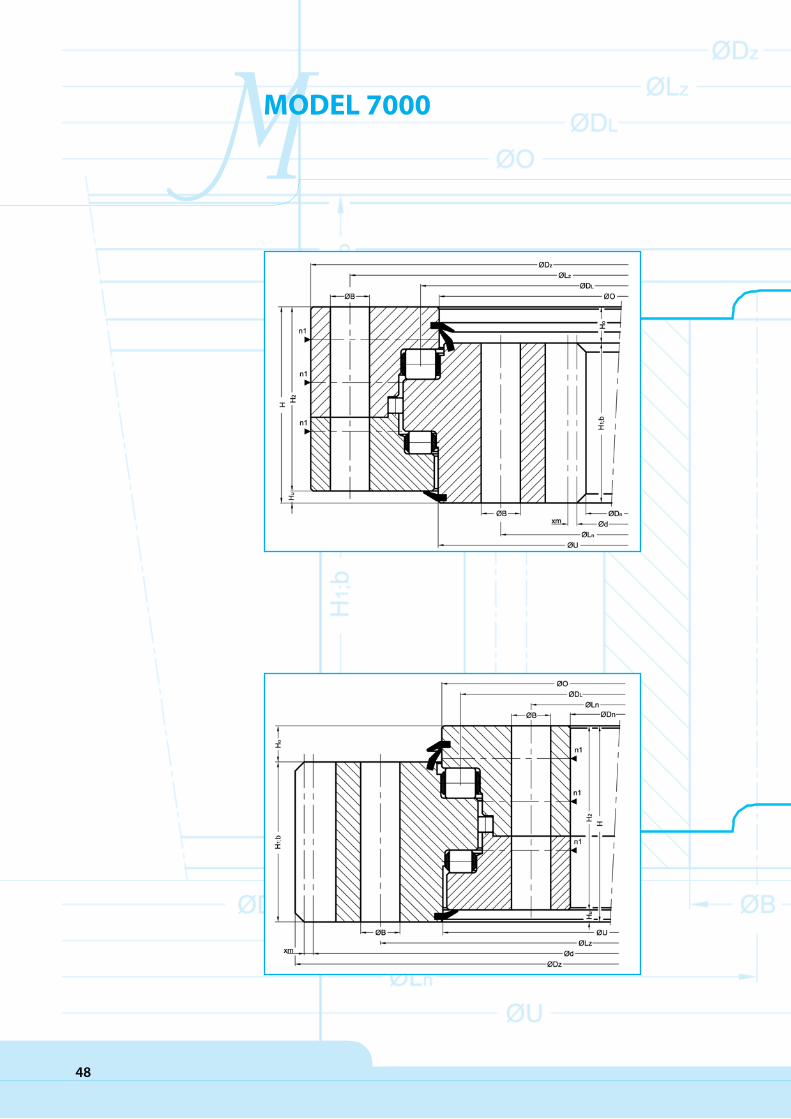
48
MMODEL 7000
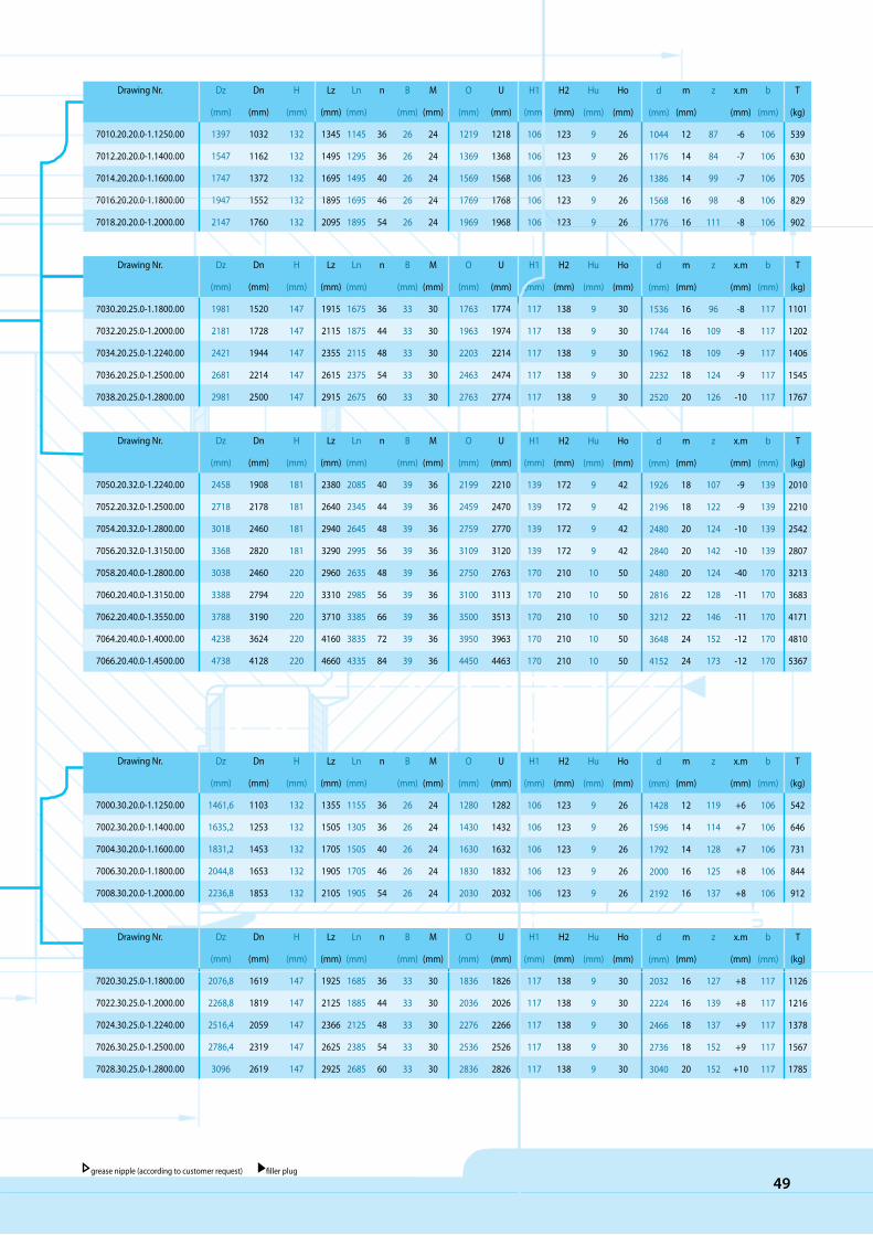
Drawing Nr.
7030.20.25.0-1.1800.00
7032.20.25.0-1.2000.00
7034.20.25.0-1.2240.00
7036.20.25.0-1.2500.00
7038.20.25.0-1.2800.00
Dz
(mm)
1981
2181
2421
2681
2981
Dn
(mm)
1520
1728
1944
2214
2500
H
(mm)
147
147
147
147
147
Lz
(mm)
1915
2115
2355
2615
2915
Ln
(mm)
1675
1875
2115
2375
2675
n
36
44
48
54
60
B
(mm)
33
33
33
33
33
M
(mm)
30
30
30
30
30
O
(mm)
1763
1963
2203
2463
2763
U
(mm)
1774
1974
2214
2474
2774
H1
(mm)
117
117
117
117
117
H2
(mm)
138
138
138
138
138
Hu
(mm)
9
9
9
9
9
Ho
(mm)
30
30
30
30
30
m
(mm)
16
16
18
18
20
z
96
109
109
124
126
x.m
(mm)
-8
-8
-9
-9
-10
b
(mm)
117
117
117
117
117
T
(kg)
1101
1202
1406
1545
1767
d
(mm)
1536
1744
1962
2232
2520
Drawing Nr.
7010.20.20.0-1.1250.00
7012.20.20.0-1.1400.00
7014.20.20.0-1.1600.00
7016.20.20.0-1.1800.00
7018.20.20.0-1.2000.00
Dz
(mm)
1397
1547
1747
1947
2147
Dn
(mm)
1032
1162
1372
1552
1760
H
(mm)
132
132
132
132
132
Lz
(mm)
1345
1495
1695
1895
2095
Ln
(mm)
1145
1295
1495
1695
1895
n
36
36
40
46
54
B
(mm)
26
26
26
26
26
M
(mm)
24
24
24
24
24
O
(mm)
1219
1369
1569
1769
1969
U
(mm)
1218
1368
1568
1768
1968
H1
(mm)
106
106
106
106
106
H2
(mm)
123
123
123
123
123
Hu
(mm)
9
9
9
9
9
Ho
(mm)
26
26
26
26
26
m
(mm)
12
14
14
16
16
z
87
84
99
98
111
x.m
(mm)
-6
-7
-7
-8
-8
b
(mm)
106
106
106
106
106
T
(kg)
539
630
705
829
902
d
(mm)
1044
1176
1386
1568
1776
49
Drawing Nr.
7020.30.25.0-1.1800.00
7022.30.25.0-1.2000.00
7024.30.25.0-1.2240.00
7026.30.25.0-1.2500.00
7028.30.25.0-1.2800.00
Dz
(mm)
2076,8
2268,8
2516,4
2786,4
3096
Dn
(mm)
1619
1819
2059
2319
2619
H
(mm)
147
147
147
147
147
Lz
(mm)
1925
2125
2366
2625
2925
Ln
(mm)
1685
1885
2125
2385
2685
n
36
44
48
54
60
B
(mm)
33
33
33
33
33
M
(mm)
30
30
30
30
30
O
(mm)
1836
2036
2276
2536
2836
U
(mm)
1826
2026
2266
2526
2826
H1
(mm)
117
117
117
117
117
H2
(mm)
138
138
138
138
138
Hu
(mm)
9
9
9
9
9
Ho
(mm)
30
30
30
30
30
m
(mm)
16
16
18
18
20
z
127
139
137
152
152
x.m
(mm)
+8
+8
+9
+9
+10
b
(mm)
117
117
117
117
117
T
(kg)
1126
1216
1378
1567
1785
d
(mm)
2032
2224
2466
2736
3040
Drawing Nr.
7000.30.20.0-1.1250.00
7002.30.20.0-1.1400.00
7004.30.20.0-1.1600.00
7006.30.20.0-1.1800.00
7008.30.20.0-1.2000.00
Dz
(mm)
1461,6
1635,2
1831,2
2044,8
2236,8
Dn
(mm)
1103
1253
1453
1653
1853
H
(mm)
132
132
132
132
132
Lz
(mm)
1355
1505
1705
1905
2105
Ln
(mm)
1155
1305
1505
1705
1905
n
36
36
40
46
54
B
(mm)
26
26
26
26
26
M
(mm)
24
24
24
24
24
O
(mm)
1280
1430
1630
1830
2030
U
(mm)
1282
1432
1632
1832
2032
H1
(mm)
106
106
106
106
106
H2
(mm)
123
123
123
123
123
Hu
(mm)
9
9
9
9
9
Ho
(mm)
26
26
26
26
26
m
(mm)
12
14
14
16
16
z
119
114
128
125
137
x.m
(mm)
+6
+7
+7
+8
+8
b
(mm)
106
106
106
106
106
T
(kg)
542
646
731
844
912
d
(mm)
1428
1596
1792
2000
2192
grease nipple (according to customer request) filler plug
Drawing Nr.
7050.20.32.0-1.2240.00
7052.20.32.0-1.2500.00
7054.20.32.0-1.2800.00
7056.20.32.0-1.3150.00
7058.20.40.0-1.2800.00
7060.20.40.0-1.3150.00
7062.20.40.0-1.3550.00
7064.20.40.0-1.4000.00
7066.20.40.0-1.4500.00
Dz
(mm)
2458
2718
3018
3368
3038
3388
3788
4238
4738
Dn
(mm)
1908
2178
2460
2820
2460
2794
3190
3624
4128
H
(mm)
181
181
181
181
220
220
220
220
220
Lz
(mm)
2380
2640
2940
3290
2960
3310
3710
4160
4660
Ln
(mm)
2085
2345
2645
2995
2635
2985
3385
3835
4335
n
40
44
48
56
48
56
66
72
84
B
(mm)
39
39
39
39
39
39
39
39
39
M
(mm)
36
36
36
36
36
36
36
36
36
O
(mm)
2199
2459
2759
3109
2750
3100
3500
3950
4450
U
(mm)
2210
2470
2770
3120
2763
3113
3513
3963
4463
H1
(mm)
139
139
139
139
170
170
170
170
170
H2
(mm)
172
172
172
172
210
210
210
210
210
Hu
(mm)
9
9
9
9
10
10
10
10
10
Ho
(mm)
42
42
42
42
50
50
50
50
50
m
(mm)
18
18
20
20
20
22
22
24
24
z
107
122
124
142
124
128
146
152
173
x.m
(mm)
-9
-9
-10
-10
-40
-11
-11
-12
-12
b
(mm)
139
139
139
139
170
170
170
170
170
T
(kg)
2010
2210
2542
2807
3213
3683
4171
4810
5367
d
(mm)
1926
2196
2480
2840
2480
2816
3212
3648
4152

50
MMODEL 7000
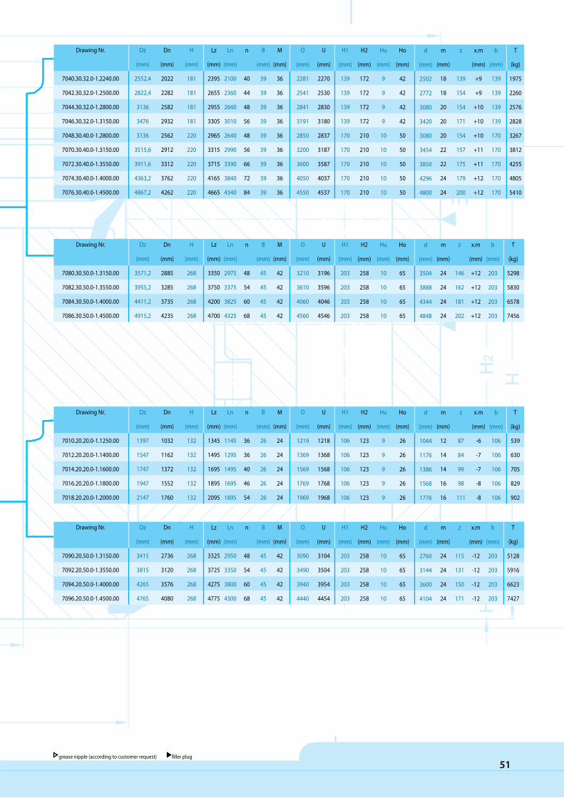
51grease nipple (according to customer request) filler plug
Drawing Nr.
7040.30.32.0-1.2240.00
7042.30.32.0-1.2500.00
7044.30.32.0-1.2800.00
7046.30.32.0-1.3150.00
7048.30.40.0-1.2800.00
7070.30.40.0-1.3150.00
7072.30.40.0-1.3550.00
7074.30.40.0-1.4000.00
7076.30.40.0-1.4500.00
Dz
(mm)
2552,4
2822,4
3136
3476
3136
3515,6
3911,6
4363,2
4867,2
Dn
(mm)
2022
2282
2582
2932
2562
2912
3312
3762
4262
H
(mm)
181
181
181
181
220
220
220
220
220
Lz
(mm)
2395
2655
2955
3305
2965
3315
3715
4165
4665
Ln
(mm)
2100
2360
2660
3010
2640
2990
3390
3840
4340
n
40
44
48
56
48
56
66
72
84
B
(mm)
39
39
39
39
39
39
39
39
39
M
(mm)
36
36
36
36
36
36
36
36
36
O
(mm)
2281
2541
2841
3191
2850
3200
3600
4050
4550
U
(mm)
2270
2530
2830
3180
2837
3187
3587
4037
4537
H1
(mm)
139
139
139
139
170
170
170
170
170
H2
(mm)
172
172
172
172
210
210
210
210
210
Hu
(mm)
9
9
9
9
10
10
10
10
10
Ho
(mm)
42
42
42
42
50
50
50
50
50
m
(mm)
18
18
20
20
20
22
22
24
24
z
139
154
154
171
154
157
175
179
200
x.m
(mm)
+9
+9
+10
+10
+10
+11
+11
+12
+12
b
(mm)
139
139
139
139
170
170
170
170
170
T
(kg)
1975
2260
2576
2828
3267
3812
4255
4805
5410
d
(mm)
2502
2772
3080
3420
3080
3454
3850
4296
4800
Drawing Nr.
7010.20.20.0-1.1250.00
7012.20.20.0-1.1400.00
7014.20.20.0-1.1600.00
7016.20.20.0-1.1800.00
7018.20.20.0-1.2000.00
Dz
(mm)
1397
1547
1747
1947
2147
Dn
(mm)
1032
1162
1372
1552
1760
H
(mm)
132
132
132
132
132
Lz
(mm)
1345
1495
1695
1895
2095
Ln
(mm)
1145
1295
1495
1695
1895
n
36
36
40
46
54
B
(mm)
26
26
26
26
26
M
(mm)
24
24
24
24
24
O
(mm)
1219
1369
1569
1769
1969
U
(mm)
1218
1368
1568
1768
1968
H1
(mm)
106
106
106
106
106
H2
(mm)
123
123
123
123
123
Hu
(mm)
9
9
9
9
9
Ho
(mm)
26
26
26
26
26
m
(mm)
12
14
14
16
16
z
87
84
99
98
111
x.m
(mm)
-6
-7
-7
-8
-8
b
(mm)
106
106
106
106
106
T
(kg)
539
630
705
829
902
d
(mm)
1044
1176
1386
1568
1776
Drawing Nr.
7080.30.50.0-1.3150.00
7082.30.50.0-1.3550.00
7084.30.50.0-1.4000.00
7086.30.50.0-1.4500.00
Dz
(mm)
3571,2
3955,2
4411,2
4915,2
Dn
(mm)
2885
3285
3735
4235
H
(mm)
268
268
268
268
Lz
(mm)
3350
3750
4200
4700
Ln
(mm)
2975
3375
3825
4325
n
48
54
60
68
B
(mm)
45
45
45
45
M
(mm)
42
42
42
42
O
(mm)
3210
3610
4060
4560
U
(mm)
3196
3596
4046
4546
H1
(mm)
203
203
203
203
H2
(mm)
258
258
258
258
Hu
(mm)
10
10
10
10
Ho
(mm)
65
65
65
65
m
(mm)
24
24
24
24
z
146
162
181
202
x.m
(mm)
+12
+12
+12
+12
b
(mm)
203
203
203
203
T
(kg)
5298
5830
6578
7456
d
(mm)
3504
3888
4344
4848
Drawing Nr.
7090.20.50.0-1.3150.00
7092.20.50.0-1.3550.00
7094.20.50.0-1.4000.00
7096.20.50.0-1.4500.00
Dz
(mm)
3415
3815
4265
4765
Dn
(mm)
2736
3120
3576
4080
H
(mm)
268
268
268
268
Lz
(mm)
3325
3725
4275
4775
Ln
(mm)
2950
3350
3800
4300
n
48
54
60
68
B
(mm)
45
45
45
45
M
(mm)
42
42
42
42
O
(mm)
3090
3490
3940
4440
U
(mm)
3104
3504
3954
4454
H1
(mm)
203
203
203
203
H2
(mm)
258
258
258
258
Hu
(mm)
10
10
10
10
Ho
(mm)
65
65
65
65
m
(mm)
24
24
24
24
z
115
131
150
171
x.m
(mm)
-12
-12
-12
-12
b
(mm)
203
203
203
203
T
(kg)
5128
5916
6623
7427
d
(mm)
2760
3144
3600
4104

52
CCARE FOR PRODUCT QUALITY
CARE FOR PRODUCT QUALITY
The quality of the products is one of the main goals of our company. Our care for the quality begins at the very start of the
production process which is the design of the product and it continues through all the stages of production until the final
shipment to the customer. Our company offers full technical support to our clients. We make sure that our products fulfil
all the customer’s expectations and requirements.
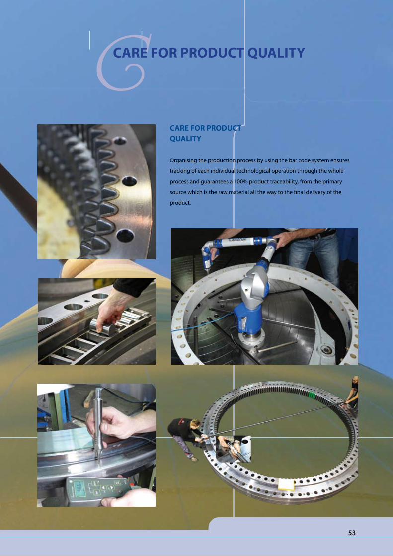
53
CARE FOR PRODUCT QUALITY
Organising the production process by using the bar code system ensures
tracking of each individual technological operation through the whole
process and guarantees a 100% product traceability, from the primary
source which is the raw material all the way to the final delivery of the
product.
CCARE FOR PRODUCT QUALITY

QQUALITY

production: SISTEMI marketing agency
August 2012

COMPANY FOR PRODUCTION, TRADE, IMPORT AND EXPORTBrodišče 5, 1236 Trzin, Slovenia;
Tel.: ++386 1/530 09 60, Fax: ++386 1/530 09 70e-mail:[email protected], http://www.rotis-lj.si
SIST
EMI.s
i 08/
012
SRB
Kočevje
Ljubl jana
SLO
CRO
R. Slovenia: L jubl jana - Tr z in , Kočevje
R. Croatia : Labin
R. S erbia : Beograd, Vrdnik
SLO
CRO
SRB


