

<photo of assembled Smart Battery Meter>
Smart Battery Meter
Assembly Instructions
Written by Dale Wheat – 26 April 2009
Contents Step 1: Parts check ....................................................................................................................................... 2 Step 2: Tool check ........................................................................................................................................ 3 Step 3: Install the resistors ........................................................................................................................... 4 Step 4: Install the microcontroller chip ........................................................................................................ 6 Step 5: Install the LEDs ................................................................................................................................. 8 Step 6: Install the calibration potentiometer .............................................................................................. 8 Step 7: Install the terminal block ................................................................................................................. 9 Step 8: Install the capacitor ....................................................................................................................... 10 Step 9: Install the voltage regulator ........................................................................................................... 11 Step 10: Calibration procedure .................................................................................................................. 11 Step 11: Testing .......................................................................................................................................... 11 Step 12: Installation ................................................................................................................................... 11
Thank you! I certainly appreciate your interest in the Smart Battery Meter project. Thank you for reading these
assembly instructions. You are obviously a cut above the rest. Your attention to detail and sense of
quality has been duly noted.
The Smart Battery Meter was designed to be easy to assemble. The assembly of the Smart Battery
Meter should take between twenty minutes to an hour, depending on your familiarity with the included
components. Please take your time and enjoy the build process. You will be rewarded with a quality
measurement device that should serve you well for many years.
Please let me know if you have any questions or comments about either the Smart Battery Meter
project or these instructions. I hope you enjoy working with the Smart Battery Meter project as much as
I have.
Dale Wheat 26 April 2009 http://dalewheat.com/slameter
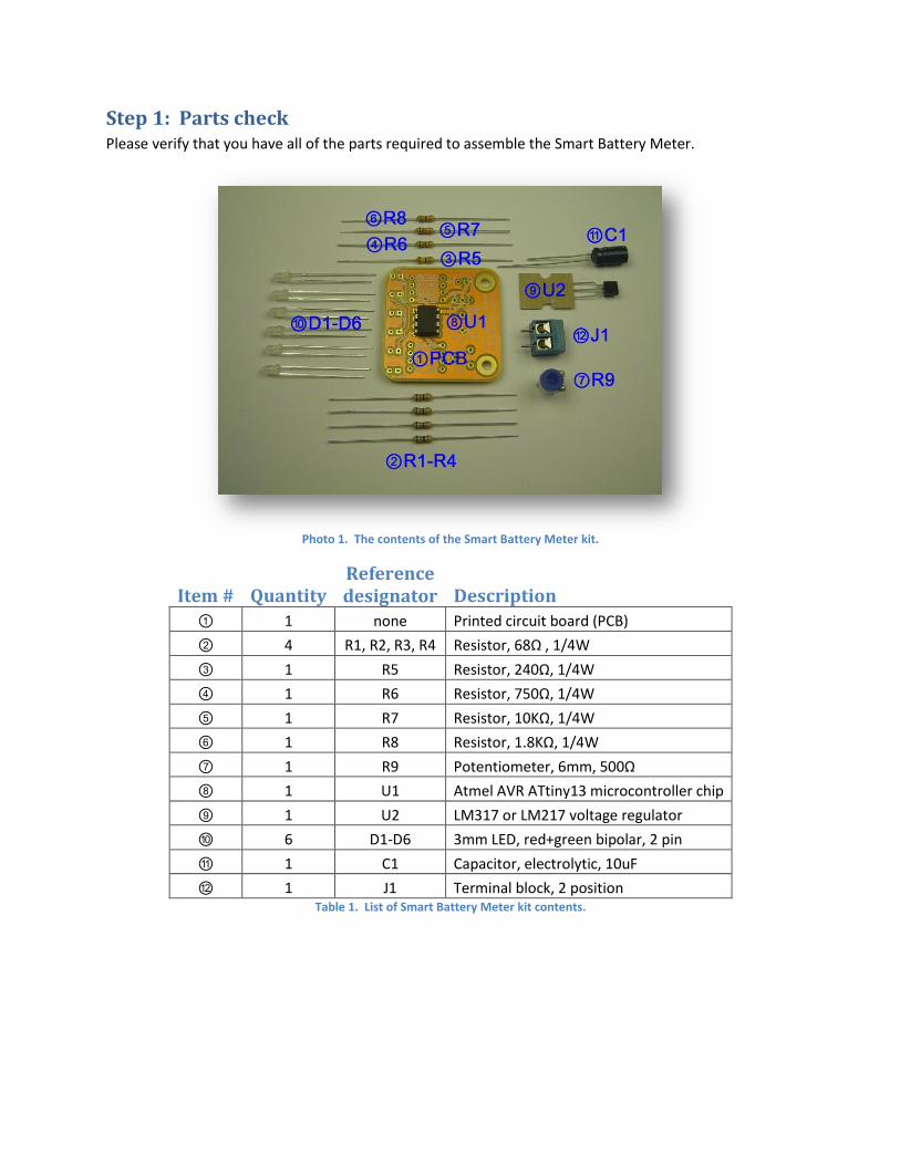
Step 1: Parts check Please verify that you have all of the parts required to assemble the Smart Battery Meter.
Photo 1. The contents of the Smart Battery Meter kit.
Item # Quantity Reference designator Description
① 1 none Printed circuit board (PCB)
② 4 R1, R2, R3, R4 Resistor, 68Ω , 1/4W
③ 1 R5 Resistor, 240Ω, 1/4W
④ 1 R6 Resistor, 750Ω, 1/4W
⑤ 1 R7 Resistor, 10KΩ, 1/4W
⑥ 1 R8 Resistor, 1.8KΩ, 1/4W
⑦ 1 R9 Potentiometer, 6mm, 500Ω
⑧ 1 U1 Atmel AVR ATtiny13 microcontroller chip
⑨ 1 U2 LM317 or LM217 voltage regulator
⑩ 6 D1-D6 3mm LED, red+green bipolar, 2 pin
⑪ 1 C1 Capacitor, electrolytic, 10uF
⑫ 1 J1 Terminal block, 2 position Table 1. List of Smart Battery Meter kit contents.

Step 2: Tool check The construction of the Smart Battery Meter consists of two stages. In the first stage you install the
individual components on the printed circuit board (PCB). Once assembled, the unit is tested and
calibrated in the second stage.
Step 2a: Assembly To assemble the Smart Battery meter, you will need the following tools, as well as the skill to use them:
Soldering iron and solder
Use a small soldering iron in the 15-30 watt range. You’re
looking for something with a “pencil grip”. Anything with a
“pistol grip” is most likely too large. A higher-powered iron
with a temperature controlled output will also work well.
Use a small gauge wire solder that contains flux. Almost
anything will do. You can use lead-free solder if you like but
there may be long-term reliability problems with lead-free
solder.
Side cutters
You could almost use scissors to trim the leads during the assembly of the 12
Volt Dimmer kit, but you will find that the right tool for the job is a pair of
“side cutters” or “flush cutters”. They allow you to get the cutting parts right
up against edge of the solder joint and cut the majority of the excess lead off
cleanly and safely. You really should wear safety glasses when soldering and
especially when cutting leads. They have a bad habit of jumping up and flying
this way and that.
Step 2b: Calibration To test and calibrate the Smart Battery Meter, you will need the following test equipment, as well as a
knowledge of their use:
Adjustable voltage reference
The Smart Battery Meter is calibrated by applying a fixed 7.500 volt supply to the unit and adjusting the
calibration adjustment (R9) until the proper calibration pattern appears on the LED display. The
precision of your voltage reference will determine the effective accuracy of the Smart Battery Meter.
Voltage meter
If your adjustable voltage reference has its own accurate voltmeter, you can use that to set the output
to the correct level. If not, you will need a separate voltage meter to verify the reference voltage.
A three and a half (3.5) digit digital voltage meter should be sufficient.
Step 3: Install the resistors There are eight (8) fixed resistors, R1-R8, and one variable resistor, R9, in the Smart Battery Meter
circuit. We will begin by installing the fixed resistors. The variable resistor, a potentiometer, will be
installed in Step 6.
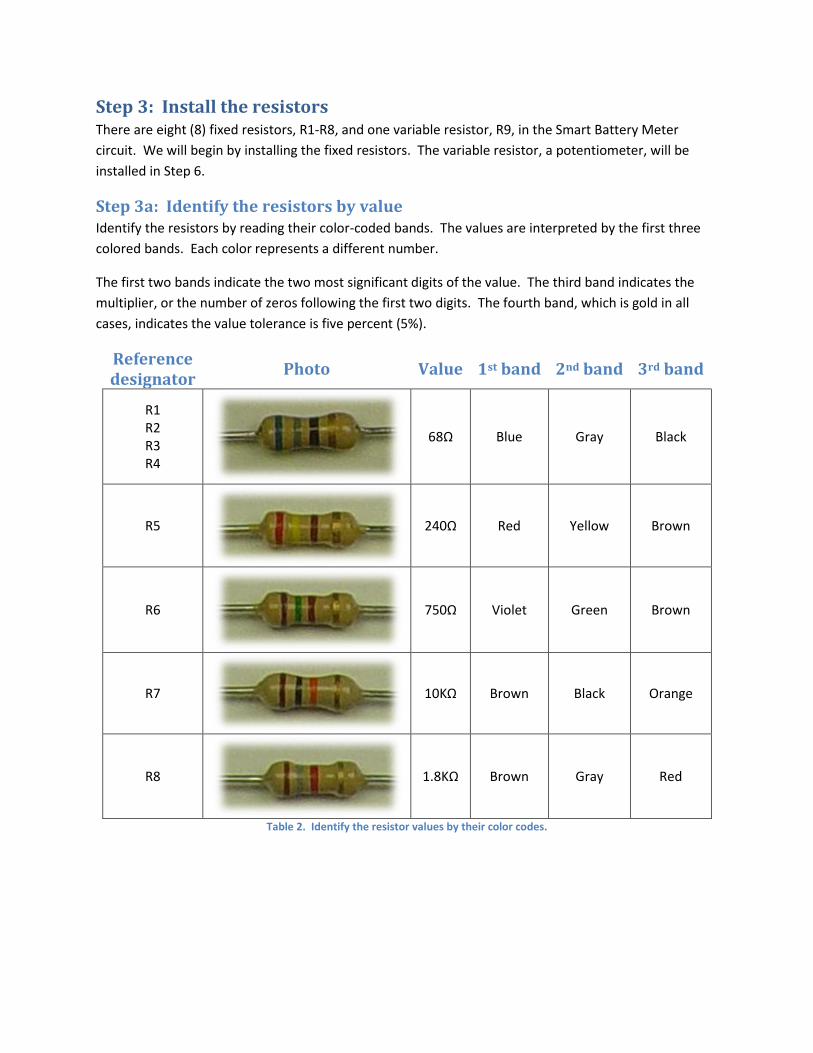
Step 3a: Identify the resistors by value Identify the resistors by reading their color-coded bands. The values are interpreted by the first three
colored bands. Each color represents a different number.
The first two bands indicate the two most significant digits of the value. The third band indicates the
multiplier, or the number of zeros following the first two digits. The fourth band, which is gold in all
cases, indicates the value tolerance is five percent (5%).
Reference designator
Photo Value 1st band 2nd band 3rd band
R1 R2 R3 R4
68Ω Blue Gray Black
R5
240Ω Red Yellow Brown
R6
750Ω Violet Green Brown
R7
10KΩ Brown Black Orange
R8
1.8KΩ Brown Gray Red
Table 2. Identify the resistor values by their color codes.
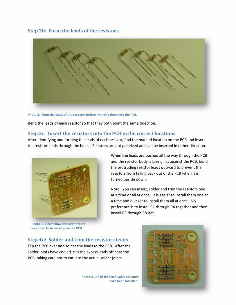
Step 3b: Form the leads of the resistors
Photo 2. Form the leads of the resistors before inserting them into the PCB.
Bend the leads of each resistor so that they both point the same direction.
Step 3c: Insert the resistors into the PCB in the correct locations After identifying and forming the leads of each resistor, find the marked location on the PCB and insert
the resistor leads through the holes. Resistors are not polarized and can be inserted in either direction.
When the leads are pushed all the way through the PCB
and the resistor body is laying flat against the PCB, bend
the protruding resistor leads outward to prevent the
resistors from falling back out of the PCB when it is
turned upside down.
Note: You can insert, solder and trim the resistors one
at a time or all at once. It is easier to install them one at
a time and quicker to install them all at once. My
preference is to install R1 through R4 together and then
install R5 through R8 last.
Step 4d: Solder and trim the resistors leads Flip the PCB over and solder the leads to the PCB. After the
solder joints have cooled, clip the excess leads off near the
PCB, taking care not to cut into the actual solder joints.
Photo 3. Here's how the resistors are supposed to be inserted in the PCB.
Photo 4. All of the fixed-value resistors have been installed.
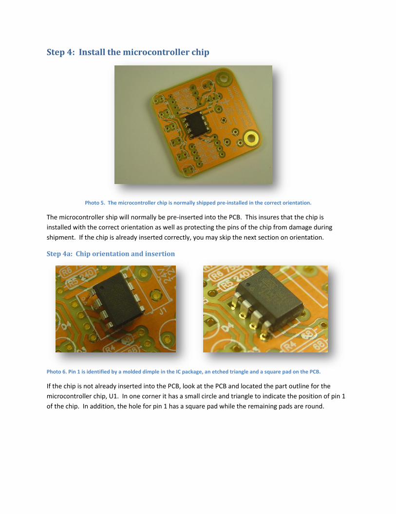
Step 4: Install the microcontroller chip
Photo 5. The microcontroller chip is normally shipped pre-installed in the correct orientation.
The microcontroller ship will normally be pre-inserted into the PCB. This insures that the chip is
installed with the correct orientation as well as protecting the pins of the chip from damage during
shipment. If the chip is already inserted correctly, you may skip the next section on orientation.
Step 4a: Chip orientation and insertion
Photo 6. Pin 1 is identified by a molded dimple in the IC package, an etched triangle and a square pad on the PCB.
If the chip is not already inserted into the PCB, look at the PCB and located the part outline for the
microcontroller chip, U1. In one corner it has a small circle and triangle to indicate the position of pin 1
of the chip. In addition, the hole for pin 1 has a square pad while the remaining pads are round.
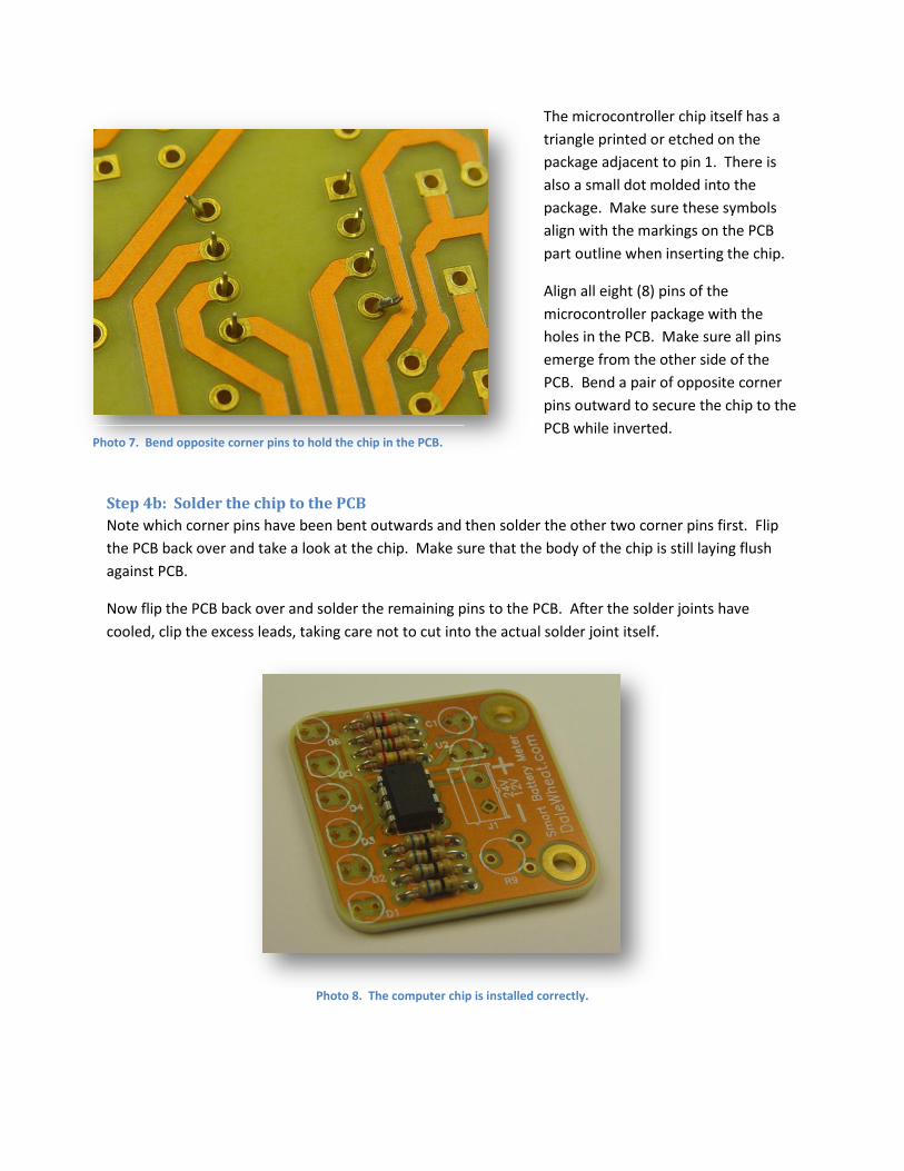
The microcontroller chip itself has a
triangle printed or etched on the
package adjacent to pin 1. There is
also a small dot molded into the
package. Make sure these symbols
align with the markings on the PCB
part outline when inserting the chip.
Align all eight (8) pins of the
microcontroller package with the
holes in the PCB. Make sure all pins
emerge from the other side of the
PCB. Bend a pair of opposite corner
pins outward to secure the chip to the
PCB while inverted.
Step 4b: Solder the chip to the PCB
Note which corner pins have been bent outwards and then solder the other two corner pins first. Flip
the PCB back over and take a look at the chip. Make sure that the body of the chip is still laying flush
against PCB.
Now flip the PCB back over and solder the remaining pins to the PCB. After the solder joints have
cooled, clip the excess leads, taking care not to cut into the actual solder joint itself.
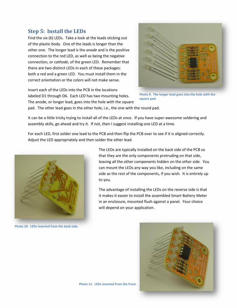
Photo 8. The computer chip is installed correctly.
Photo 7. Bend opposite corner pins to hold the chip in the PCB.
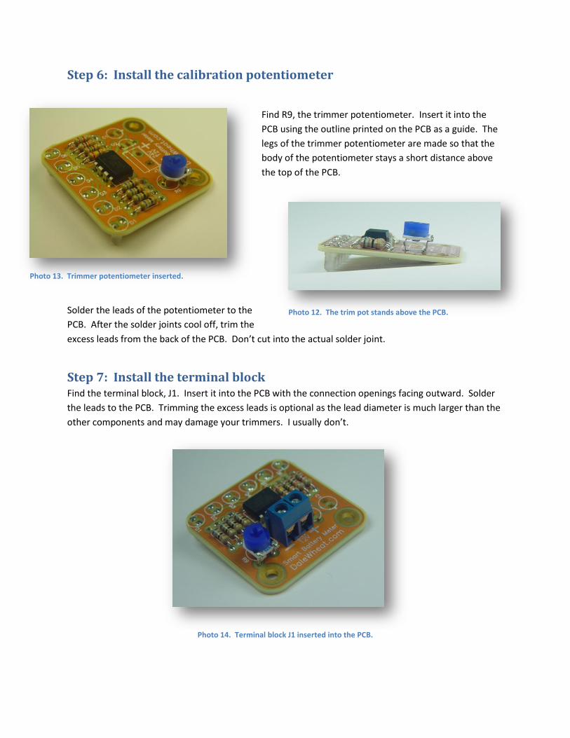
Step 5: Install the LEDs Find the six (6) LEDs. Take a look at the leads sticking out
of the plastic body. One of the leads is longer than the
other one. The longer lead is the anode and is the positive
connection to the red LED, as well as being the negative
connection, or cathode, of the green LED. Remember that
there are two distinct LEDs in each of these packages:
both a red and a green LED. You must install them in the
correct orientation or the colors will not make sense.
Insert each of the LEDs into the PCB in the locations
labeled D1 through D6. Each LED has two mounting holes.
The anode, or longer lead, goes into the hole with the square
pad. The other lead goes in the other hole, i.e., the one with the round pad.
It can be a little tricky trying to install all of the LEDs at once. If you have super-awesome soldering and
assembly skills, go ahead and try it. If not, then I suggest installing one LED at a time.
For each LED, first solder one lead to the PCB and then flip the PCB over to see if it is aligned correctly.
Adjust the LED appropriately and then solder the other lead.
The LEDs are typically installed on the back side of the PCB so
that they are the only components protruding on that side,
leaving all the other components hidden on the other side. You
can mount the LEDs any way you like, including on the same
side as the rest of the components, if you wish. It is entirely up
to you.
The advantage of installing the LEDs on the reverse side is that
it makes it easier to install the assembled Smart Battery Meter
in an enclosure, mounted flush against a panel. Your choice
will depend on your application.
Photo 11. LEDs inserted from the front.
Photo 10. LEDs inserted from the back side.
Photo 9. The longer lead goes into the hole with the square pad.
Step 6: Install the calibration potentiometer
Find R9, the trimmer potentiometer. Insert it into the
PCB using the outline printed on the PCB as a guide. The
legs of the trimmer potentiometer are made so that the
body of the potentiometer stays a short distance above
the top of the PCB.
Solder the leads of the potentiometer to the
PCB. After the solder joints cool off, trim the
excess leads from the back of the PCB. Don’t cut into the actual solder joint.
Step 7: Install the terminal block Find the terminal block, J1. Insert it into the PCB with the connection openings facing outward. Solder
the leads to the PCB. Trimming the excess leads is optional as the lead diameter is much larger than the
other components and may damage your trimmers. I usually don’t.
Photo 14. Terminal block J1 inserted into the PCB.
Photo 12. The trim pot stands above the PCB.
Photo 13. Trimmer potentiometer inserted.
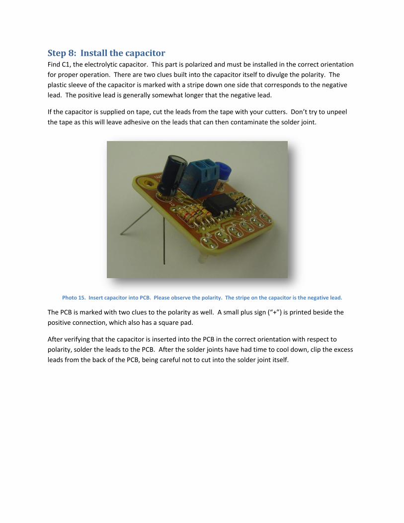
Step 8: Install the capacitor Find C1, the electrolytic capacitor. This part is polarized and must be installed in the correct orientation
for proper operation. There are two clues built into the capacitor itself to divulge the polarity. The
plastic sleeve of the capacitor is marked with a stripe down one side that corresponds to the negative
lead. The positive lead is generally somewhat longer that the negative lead.
If the capacitor is supplied on tape, cut the leads from the tape with your cutters. Don’t try to unpeel
the tape as this will leave adhesive on the leads that can then contaminate the solder joint.
Photo 15. Insert capacitor into PCB. Please observe the polarity. The stripe on the capacitor is the negative lead.
The PCB is marked with two clues to the polarity as well. A small plus sign (“+”) is printed beside the
positive connection, which also has a square pad.
After verifying that the capacitor is inserted into the PCB in the correct orientation with respect to
polarity, solder the leads to the PCB. After the solder joints have had time to cool down, clip the excess
leads from the back of the PCB, being careful not to cut into the solder joint itself.

Step 9: Install the voltage regulator
Step 10: Calibration procedure
Step 11: Testing
Step 12: Installation


