
1
SOLAR POWERED LIQUID DESICCANT
COOLING SYSTEM
TARUN B PATELME ENERGY ENGINEERING140190739009GUIDED BY – Dr K V ModiGEC VALSAD
2
Content• Paper reviewed• Work/System Description• Performance/Result• Conclusion
3
Paper Reviewed• K. Gommed et al, “Experimental investigation of a liquid desiccant system for solar cooling and dehumidification”, Solar Energy 81 (2007) 131–138.
• Rajat Subhra Das et al, “Investigations on solar energy driven liquid desiccant cooling systems for tropical climates”, Australian Solar Energy Council (2012) 978-0-646-90071-1
4
Review 1 1. K. Gommed et al, constructed a solar-driven
liquid desiccant system for cooling, dehumidification and air conditioning and tested the concept, identify problems, carried out preliminary design optimization and measure performance.
2. The system is capable of using as its source of power low-grade solar heat from low-cost flat plate collectors and has the potential to provide both cooling and dehumidification in variable ratios, as required by the load.
5
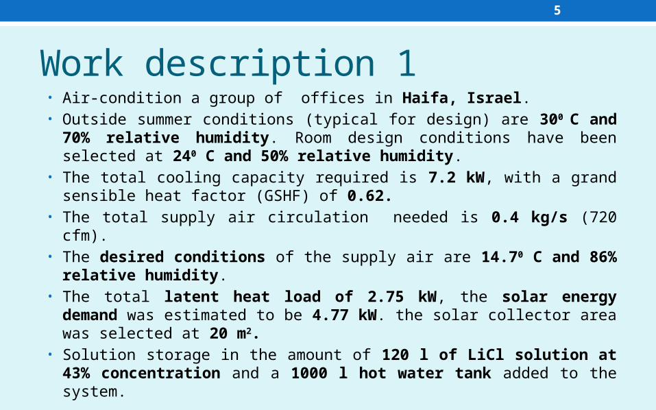
Work description 1• Air-condition a group of offices in Haifa, Israel.• Outside summer conditions (typical for design) are 300 C and
70% relative humidity. Room design conditions have been selected at 240 C and 50% relative humidity.
• The total cooling capacity required is 7.2 kW, with a grand sensible heat factor (GSHF) of 0.62.
• The total supply air circulation needed is 0.4 kg/s (720 cfm).• The desired conditions of the supply air are 14.70 C and 86%
relative humidity.• The total latent heat load of 2.75 kW, the solar energy
demand was estimated to be 4.77 kW. the solar collector area was selected at 20 m2.
• Solution storage in the amount of 120 l of LiCl solution at 43% concentration and a 1000 l hot water tank added to the system.
6
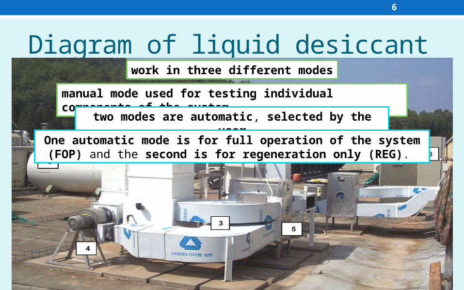
Diagram of liquid desiccantwork in three different modes
manual mode used for testing individual components of the system
two modes are automatic, selected by the user
One automatic mode is for full operation of the system (FOP) and the second is for regeneration only (REG).
7
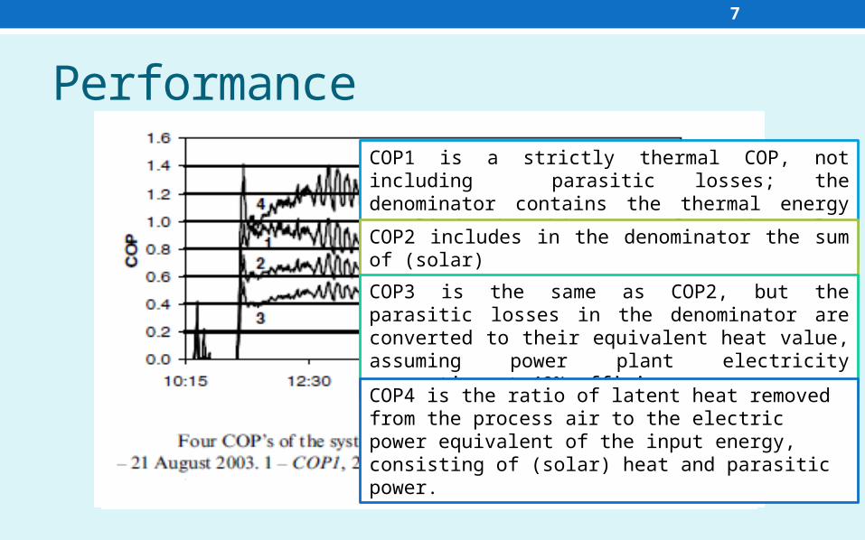
PerformanceCOP1 is a strictly thermal COP, not including parasitic losses; the denominator contains the thermal energy supplied, in this case from the solar collectors.COP2 includes in the denominator the sum of (solar)heat input and parasitic losses.COP3 is the same as COP2, but the parasitic losses in the denominator are converted to their equivalent heat value, assuming power plant electricity generation at 40% efficiency.COP4 is the ratio of latent heat removed from the process air to the electric power equivalent of the input energy, consisting of (solar) heat and parasitic power.
8
Conclusion 1• The system functioned well, with 16 kW (average) dehumidification capacity.• The data analysis indicates a thermal COP of about 0.8, with parasitic losses on the order of 10%.• The COP calculations performed on the monitoring data have yielded satisfactory results, particularly with regard to the thermal COP.
9
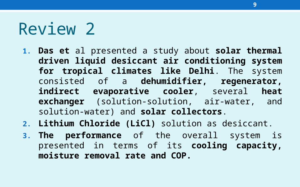
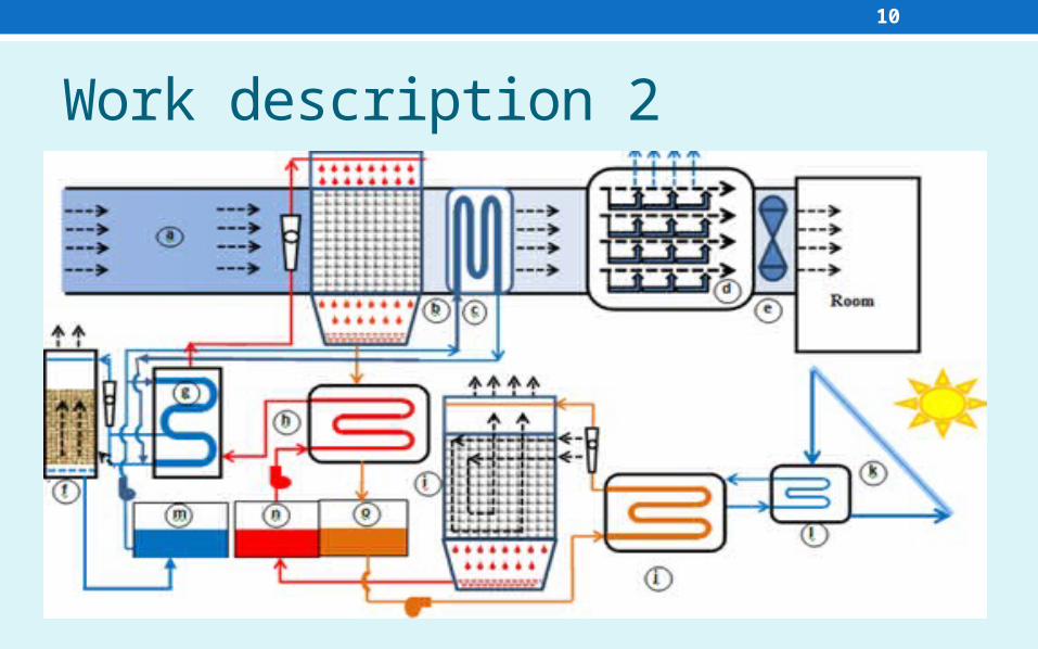
Review 21. Das et al presented a study about solar thermal
driven liquid desiccant air conditioning system for tropical climates like Delhi. The system consisted of a dehumidifier, regenerator, indirect evaporative cooler, several heat exchanger (solution-solution, air-water, and solution-water) and solar collectors.
2. Lithium Chloride (LiCl) solution as desiccant.3. The performance of the overall system is
presented in terms of its cooling capacity, moisture removal rate and COP.
10
Work description 2
11
Results 2
12
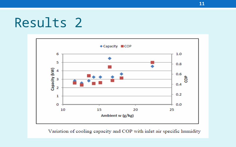
Conclusion 2• Maximum specific humidity change and moisture removal rate of 8 g/kg and 1.6 g/s is achieved.• The capacity of the system is found to vary between 2.5 to 5.5 kW and COP lies between 0.4 to 0.8, at different ambient conditions.• Both the capacity and COP of the system increase with rising specific humidity of ambient air. • There is also a slight increase in the dehumidification and enthalpy effectiveness of the dehumidifier with increasing inlet air specific humidity.

13
•THANK YOU


