

Spatter-freeignition!
Weld Package FrontPull 7
Solutions for: ABB • FANUC • KUKA • YASKAWA/MOTOMAN
The Frontpull 7 Weld Package: DCT power source • Weld process controller • Robot interface • Wire feeder• Wire guidance • Cable bundle • Control cable •
Torch system • Torch necks • Consumables
The innovative alternative to Push-Pull torch systems
Document no.: DOC-0112EN | Revision: SKSde.06DEZ19.ms.bp.v2.0.0
Spatter-free ignition!

SKS Weld Package: System design
This brochure contains information about the SKS Weld Package, the torch system Frontpull 7, as well as consumables and spare parts. There are various features of the welding machine components and torch systems available depending on the robot system and the welding task. The Frontpull 7 Weld Package can be used with common industrial robots, such as ABB, FANUC, KUKA and YASKAWA/MOTOMAN.
For installations with outer cable dress.
12
9
6
4
5
DCT power source
Robot interface
Wire feeder
Wire guidance
Cable bundle
Torch system Frontpull 7
Ground cable
Torch necks/Consumables
Control cable
Weld process controller + Software
1
5
3
7
10
2
6
9
4
8
Gas nozzles/Reamer blades
11
TCP dimensions/Checking fixtures/eReam
12

- SCHWEISSMASCHINE / WELDING MACHINE
BRENNERSYSTEM / TORCH SYSTEM SOFTWARE / IT
Processes: MIG/MAG (GMAW), Pulse, MIG Brazing, microMIG/microMIG-cc
Wire materials: High-alloy steels, low-alloy steels, aluminum and copper alloys,
nickel-based materials
Wire diameter: 0.8-1.6 mm
Max. power: 420 A - 60 % duty cycle/40 °C, air-cooled
The complete SKS Frontpull 7 Weld Package is designedfor the following welding processes, materials and power range:
8
7

Power source LSQ3
Power source LSQ5
Power source
LSQ5 power source with Direct Control Technology DCT
The LSQ5 ensures the optimum arc energy. It uniquely adjusts to different weld processes. Unlike conventional power sources with inverter technology, the LSQ5 with Direct Control Technology controls its switching transistors without any fixed clock frequency according to the needs of the weld process. Without any delay, the energy needed for the process is provided instantly. The flexible fine tuning is done by a central processor. The CPU continuously analyzes the weld process and current/voltage values on the basis of data obtained and optimally drives the switching transistors of the power section. This results in an extremely high efficiency and a low temperature development. The power source can be configured with only two buttons and four LED indicators. For world-wide usage, voltages can be configured without opening the power source.
LSQ3 power source with Direct Control Technology (DCT)The LSQ3 offers enough power reserves for special weld tasks like chassis and exhaustparts and other thin sheet metal applications.LSQ3: 340 A at 60 % duty cycle, 3 x 400 VLSQ3A: 340 A at 60 % duty cycle, 3 x 480 V
Overview of power sourcesDESCRIPTION PART-NO.LSQ5 77-1185-00LSQ3 77-1184-00LSQ3A 77-1184-10LSQ5-CCC 77-1185-60LSQ3-CCC 77-1184-40
The main benefits are: • DCT provides a speed regulation up to ten times higher compared to conventional inverter technology. This leads to excellent control behavior and shorter response times.• The weld properties are substantially improved. Software replaces hardware: Fewer components also increase the reliability in continuous operation.
Specifications:DESCRIPTION LSQ5(-CCC) LSQ3(-CCC) LSQ3A
Performance 420 A - 60% duty cycle/40 °C (400 A)
340 A - 60%duty cycle/40 °C
340 A - 60%duty cycle/40 °C
Processes MIG/MAG (GMWA), Pulse, MIG BrazingWeight 49 kg 37 kg 37 kgPrimary voltage 3 x 400 (480)V 3 x 400V 3 x 480VWall mounting Yes (optional) Yes (integrated) Yes (integrated)Conformities CE, CSA, UL (CCC) CE (CCC) CE
Dimensions 450 x 400 x 540mm 450 x 330 x 540mm 450 x 330 x 540mm
Wall mount DESCRIPTION PART-NO.Wall mount for LSQ5 77-1180-01Wall mount for LSQ3 integratedWall mount for LSQ3 A integrated
ALTERNATIVE
OPTION
Accessories: Wall mount for LSQ5
Space-saving design that makes for easy cleaning/maintenance.

Weld process controller2
3
Controlling up to four weld
machines at the same time
4 3 2 1
42
1
Innovative Control Concepts with Touch Screen.With the new Q84r and the compact Q84s up to four weld machines can be controlled centrally.
The new Q84r and Q84s are equipped with a touch screen, an innovative usability concept and an advanced visualization technology for much easier operating. The user interfaces have the look and feel of the Q8Tool4 software. Individual weld process controllers are in card slots in the Q84r/s. This new weld process controller concept can host up to four weld process controller cards. Each card independently controls a weld machine. As an alternative to the Q84r/s weld process controllers, the Q80 has been developed to control a single weld machine.
Weld process controller Q80 front view
Weld process controller Q80 back view
ALTERNATIVE
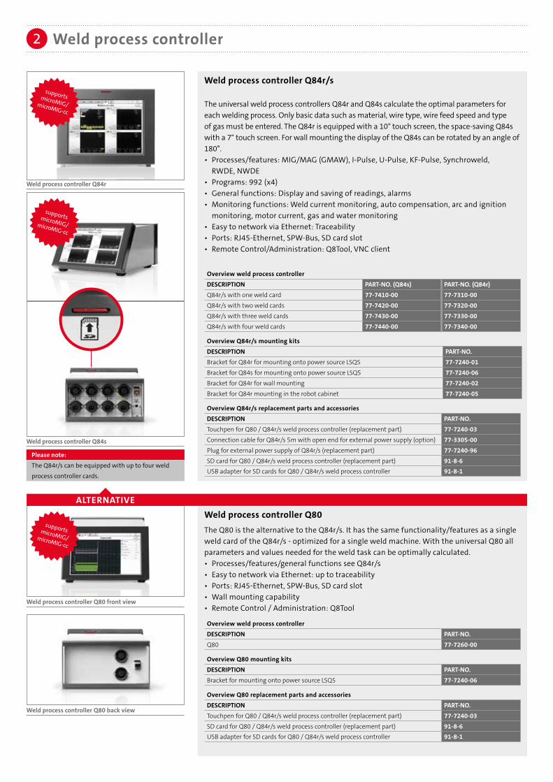
Please note:The Q84r/s can be equipped with up to four weldprocess controller cards.
Weld process controller Q84r
Weld process controller Q84s
Weld process controller2
supportsmicroMIG/ microMIG-cc
supportsmicroMIG/ microMIG-cc
supportsmicroMIG/ microMIG-cc
Weld process controller Q84r/s
The universal weld process controllers Q84r and Q84s calculate the optimal parameters for each welding process. Only basic data such as material, wire type, wire feed speed and type of gas must be entered. The Q84r is equipped with a 10" touch screen, the space-saving Q84s with a 7" touch screen. For wall mounting the display of the Q84s can be rotated by an angle of 180°.• Processes/features: MIG/MAG (GMAW), I-Pulse, U-Pulse, KF-Pulse, Synchroweld, RWDE, NWDE• Programs: 992 (x4)• General functions: Display and saving of readings, alarms• Monitoring functions: Weld current monitoring, auto compensation, arc and ignition monitoring, motor current, gas and water monitoring• Easy to network via Ethernet: Traceability• Ports: RJ45-Ethernet, SPW-Bus, SD card slot• Remote Control/Administration: Q8Tool, VNC client
Overview weld process controllerDESCRIPTION PART-NO. (Q84s) PART-NO. (Q84r)Q84r/s with one weld card 77-7410-00 77-7310-00Q84r/s with two weld cards 77-7420-00 77-7320-00Q84r/s with three weld cards 77-7430-00 77-7330-00Q84r/s with four weld cards 77-7440-00 77-7340-00
Overview Q84r/s mounting kits DESCRIPTION PART-NO.Bracket for Q84r for mounting onto power source LSQ5 77-7240-01Bracket for Q84s for mounting onto power source LSQ5 77-7240-06Bracket for Q84r for wall mounting 77-7240-02Bracket for Q84r mounting in the robot cabinet 77-7240-05
Overview Q84r/s replacement parts and accessoriesDESCRIPTION PART-NO.Touchpen for Q80 / Q84r/s weld process controller (replacement part) 77-7240-03Connection cable for Q84r/s 5m with open end for external power supply (option) 77-3305-00Plug for external power supply of Q84r/s (replacement part) 77-7240-96SD card for Q80 / Q84r/s weld process controller (replacement part) 91-8-6USB adapter for SD cards for Q80 / Q84r/s weld process controller 91-8-1
Weld process controller Q80 The Q80 is the alternative to the Q84r/s. It has the same functionality/features as a singleweld card of the Q84r/s - optimized for a single weld machine. With the universal Q80 all parameters and values needed for the weld task can be optimally calculated.• Processes/features/general functions see Q84r/s• Easy to network via Ethernet: up to traceability• Ports: RJ45-Ethernet, SPW-Bus, SD card slot• Wall mounting capability • Remote Control / Administration: Q8Tool
Overview weld process controllerDESCRIPTION PART-NO.Q80 77-7260-00
Overview Q80 mounting kitsDESCRIPTION PART-NO.Bracket for mounting onto power source LSQ5 77-7240-06
Overview Q80 replacement parts and accessoriesDESCRIPTION PART-NO.Touchpen for Q80 / Q84r/s weld process controller (replacement part) 77-7240-03SD card for Q80 / Q84r/s weld process controller (replacement part) 91-8-6USB adapter for SD cards for Q80 / Q84r/s weld process controller 91-8-1

Weld process controller2
Q8Tool software
The Q8Tool software provides accurate and comprehensive process monitoring. The user can store weld parameters for documentation on a PC and/or administrate them. It offers basic functions such as reading, modifying and documenting of weld parameters. Additionally, new weld parameters can be created and transferred to the universal weld process controllers. The weld data is portable and the installation of further control units on new equipment is easy. Also, the software allows reading and exporting of measurements and alarms. Graphical and numerical recording of measures helps defining and optimizing parameters for new parts. Users have a powerful tool for analyzing and documenting their weld results.
Network
The weld process controller units can easily be networked via Ethernet ports: Time savings through centralized administration of all controllers within the corporate network. There is a central backup of all welding parameters, management of user rights and access, process monitoring up to traceability. The Q8Tool software is provided free of charge with the weld process controller. No additional hardware or software is required.
Software/IT2a
ALTERNATIVE
Weld process controller Q4Weld process controller Q4 as integratedsolution into the power source
Weld process controller Q6pw
Weld process controller Q6pw and Q4
The perfect solution for local administration – the weld process controllers Q6pw and Q4 provide all basic functions of the Q80. The controllers can be administrated over the USB port with the Q8TOOL4 software. As a small and compact solution for the cost-optimized application, the Q4 is integrated into the power sources LSQ3 or LSQ5.• Processes/features: MIG/MAG (GMAW), I-Pulse, U-Pulse, KF-Pulse• Programs: 186• General functions: Display and saving of readings, alarms• Monitoring functions: Weld current monitoring, auto compensation, arc and ignition monitoring,motor current, gas and water monitoring• Ports: RS232 (Q6pw only), SPW-Bus (Q6pw only), USB
Overview weld process controllerDESCRIPTION PART-NO. Please note:Q6pw 77-7230-00 The Q4 weld process
controller is integratedinto the front of thepower source and isdelivered with the powersource.
Q4/LSQ5 77-1185-20Q4/LSQ3 77-1184-20Q4/LSQ3A 77-1184-30Q4/LSQ5-CCC 77-1185-21Q4/LSQ3-CCC 77-1184-21
Robot interface3
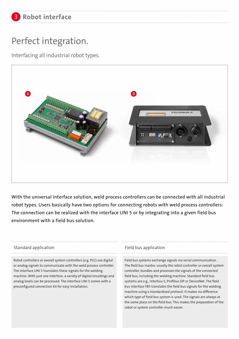
Perfect integration.Interfacing all industrial robot types.
With the universal interface solution, weld process controllers can be connected with all industrial
robot types. Users basically have two options for connecting robots with weld process controllers: The connection can be realized with the interface UNI 5 or by integrating into a given field bus environment with a field bus solution.
Robot controllers or overall system controllers (e.g. PLC) use digital or analog signals to communicate with the weld process controller. The interface UNI 5 translates these signals for the welding machine. With just one interface, a variety of digital encodings and analog levels can be processed. The interface UNI 5 comes with a preconfigured connection kit for easy installation.
Field bus systems exchange signals via serial communication. The field bus master, usually the robot controller or overall system controller, bundles and processes the signals of the connected field bus, including the welding machine. Standard field bus systems are e.g., Interbus-S, Profibus DP or DeviceNet. The field bus interface FB5 translates the field bus signals for the welding machine using a standardized protocol. It makes no difference which type of field bus system is used. The signals are always at the same place on the field bus. This makes the preparation of the robot or system controller much easier.
Standard application Field bus application
A B

Robot interface UNI 5
The interface connects the welding equipment with all industrial robot types. With its high degree of standardization, the UNI 5 is the perfect choice for connecting the weld process controller (e.g. Q80) with an industrial robot. The UNI 5 comes preprogrammed and configured for different robot types. Configuration to a particular robot type is handled easily by programming the interface with two buttons for the given robot type.
Overview of robot interfacesDESCRIPTION PART-NO.For robot type-ABBUNI 5A for IRC5 77-8011-08
For robot type-FANUCUNI 5A for RJ3iC 77-8001-84
For robot type-KUKAUNI 5A for KR C2 77-8011-08
For robot type-YASKAWA/MOTOMAN
UNI 5C (Synchroweld over RS232) for NX 100 / DX 100 / DX 200 77-8013-00
Robot interface3
ALTERNATIVE
A
B
Synchroweld unites the weld system and robot by a communication protocol (RWDE). This technology allows the weld system to get the actual robot speed and automatically adjusts the weld parame-ters accordingly. The result is a constant energy per unit length. At the same time, the programming effort can be signifi-cantly reduced.
OPTION
Please note:
Further information on Synchroweld with ABB, Fanuc, KUKA, Yaskawa/Motoman can be found in our Synchroweld brochure.
Field bus application
Various field bus types are supported (e.g. Profibus DP, DeviceNet). The field bus interface has drilled bore holes for flexible mounting within the weld cell. Two additional mounting kits provide easy installation at the power source or into the cabinet. Additionally, external power can be connected to the interface. More details on solutions for the specific field bus types are available on request.
Overview FB5 interfacesDESCRIPTION PART-NO.
Interbus-S (copper line) 77-3-1
Profibus DP 77-3-2DeviceNet 77-3-3EtherCAT 77-3-4Profinet IRT (copper line) 77-3-5Profinet IRT (LWL 2 ports) 77-3-6Interbus-S (LWL FSMA) 77-3-7Ethernet/IP 77-3-8
Cabinet mountingDESCRIPTION PART-NO.Mounting kit for cabinet 77-1182-02Control cable with bracket 77-3102-02
Power source mountingDESCRIPTION PART-NO.Mounting kit for power source 77-1182-03
Optional power supply (24V)DESCRIPTION PART-NO.Connection cable 2.0 m (with open end) 77-1182-04
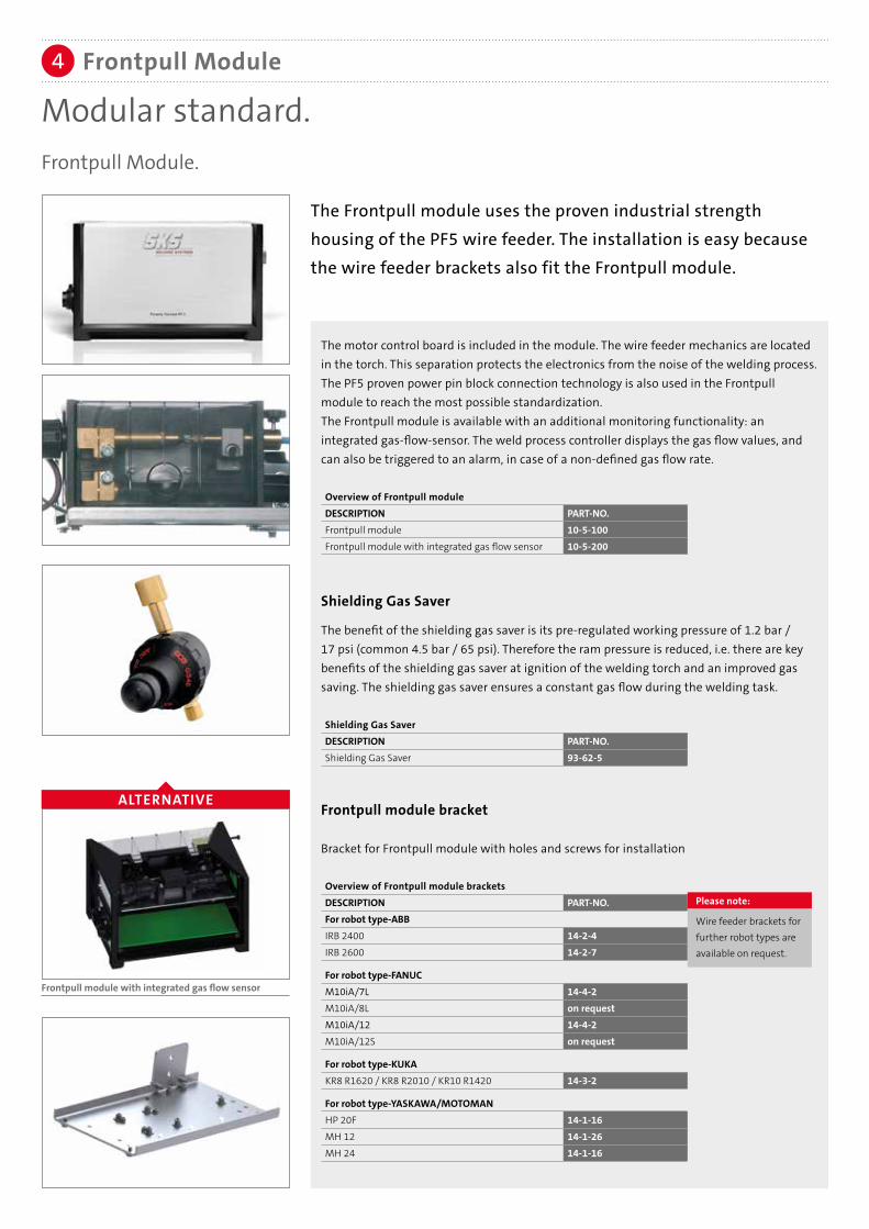
Modular standard.Frontpull Module.
The Frontpull module uses the proven industrial strength housing of the PF5 wire feeder. The installation is easy because the wire feeder brackets also fit the Frontpull module.
The motor control board is included in the module. The wire feeder mechanics are located in the torch. This separation protects the electronics from the noise of the welding process. The PF5 proven power pin block connection technology is also used in the Frontpull module to reach the most possible standardization.The Frontpull module is available with an additional monitoring functionality: an integrated gas-flow-sensor. The weld process controller displays the gas flow values, and can also be triggered to an alarm, in case of a non-defined gas flow rate.
Overview of Frontpull moduleDESCRIPTION PART-NO.Frontpull module 10-5-100Frontpull module with integrated gas flow sensor 10-5-200
Frontpull Module4
ALTERNATIVE
Frontpull module with integrated gas flow sensor
Frontpull module bracket
Bracket for Frontpull module with holes and screws for installation
Overview of Frontpull module bracketsDESCRIPTION PART-NO.For robot type-ABBIRB 2400 14-2-4IRB 2600 14-2-7
For robot type-FANUCM10iA/7L 14-4-2M10iA/8L on requestM10iA/12 14-4-2M10iA/12S on request
For robot type-KUKAKR8 R1620 / KR8 R2010 / KR10 R1420 14-3-2
For robot type-YASKAWA/MOTOMANHP 20F 14-1-16MH 12 14-1-26MH 24 14-1-16
Please note:
Wire feeder brackets for further robot types are available on request.
The benefit of the shielding gas saver is its pre-regulated working pressure of 1.2 bar / 17 psi (common 4.5 bar / 65 psi). Therefore the ram pressure is reduced, i.e. there are key benefits of the shielding gas saver at ignition of the welding torch and an improved gas saving. The shielding gas saver ensures a constant gas flow during the welding task.
Shielding Gas SaverDESCRIPTION PART-NO.Shielding Gas Saver 93-62-5
Shielding Gas Saver

Wire guidance polymer for aluminum wires5
With the new SKS polymer guidance, the high efficiency of the whole system extends up to the drum.Advantages of polymer wire guidance• Extraordinary good glide properties reduces motor load• Minimized abrasive wear and reduced dirt in wire feeder and torch system• Lightweight design and a high inherent stability for easy installation• Length can be freely chosen by the customer• Cost optimized exchange: only the polymer conduit must be changed, connectors are reuseable.• Optimized materials for longer life and reduced downtimes
Wire inlet body with quick
coupling
Connection nipple for polymer conduit
Polymer conduit
Drum connector with ceramic inlay
1
4
2
3
1
4
2
3
Please note:
Furhter information can be found in our brochure "Wire guidance" (DOC-0193EN).
1
Wire inlet body, Connection nipple, Polymer conduit and Connection for wire drum
Wire inlet body with quick couplingDESCRIPTION PART-NO.Wire Inlet body with quick lock and polymeric inlet 10-2-0-63Polymeric inlet (spare part) 10-2-0-63-2Inset for aluminum wire 10-2-0-57-3
Connection nipple for polymer conduit DESCRIPTION PART-NO.Connection nipple 44-40-3
Polymer wire conduitDESCRIPTION PART-NO.Polymer wire conduit, blue, per meter 44-9-1
Connection for wire drumDESCRIPTION PART-NO.Drum connector with ceramic inlay 44-40-1
OPTIONDESCRIPTION PART-NO.Strain-Relief for wire guidance 14-10-6
Please note:
Two connection nipples are necessary.

With the ERC wire guidance for steel/stainless steel, the high efficiency of the whole system extends up to the drum.
Advantages• Very good inherent stability due to thick polyethylene insulating jacket• Good sliding properties• Reduced wear by using flat wire for monocoil core• Suitable for steel and stainless steel wires
Wire guidance ERCDESCRIPTION PART-NO.Wire inlet body with quick coupling 10-2-0-61Connection nipple for ERC conduit 44-70-2Polymer wire conduit ERC / per meter 44-70-1 Drum connector with ceramic inlay 44-40-1
1
4
2
3
1 2
3
2
4
Wire inlet body with quick coupling
Connection nipple for ERC conduit
Polymer wire conduit ERC
Connection for wire drum with inner ceramic inlay
Please note:
Two connection nipples are necessary.
OPTIONDESCRIPTION PART-NO.Strain Relief for wire guidance 14-10-6Strain Relief spring for wire guidance 44-70-3
Wire guidance ERC for steel and stainless steel wire materials5
Wire inlet bodies for additional systemsBeside the wire inlet body for the SKS wire guidance, inlet bodiesfor additional systems are available.
Overview of wire inlet bodies for additional systemsDESCRIPTION PART-NO.M10 with internal thread for ESAB 10-2-0-50UNF 3/8" x 24 with external thread 10-2-0-51with 9.6 mm bore hole 10-2-0-52with 13 mm bore hole 10-2-0-53with PG9 thread 10-2-0-56with 1/4” internal thread 10-2-0-60
Aluminum inlets for wire inlet bodiesDESCRIPTION PART-NO.for types 50/52/53/54/59/60/61 10-2-0-57-3for types 51/55/56 10-2-0-58-3
ALTERNATIVE

Ground cable with 70 mm2 connector and cable plug
Cables with larger diameters are available on request
Overview of ground cablesLENGTH PART-NO.6 m 22807810610 m 228078100
The advantages of a system concept are revealed by its details: One standard control cable (L700) connects all system components (power source, robot interface, weld process controller and Frontpull module) within the welding system. The system is expandable: Other components can be integrated at any time into an existing system. New devices are automatically detected.
Control cable: L700/SPW-bus
Standard control cable to connect the components:Weld process controller, power source, robot interface, wire feeder.
Overview of control cablesLENGTH PART-NO.0.5 m 5410310501 m 5410310012 m 5410310023 m 5410310035 m 5410310057 m 54103100710 m 54103100012 m 54103101215 m 541031015
Ground cable
Control cable
6
7
PLUG & PLAY: CONTROL CABLE L700
POWER SOURCE ROBOT INTERFACE WELD PROCESS CONTROLLER
Please note:For the Frontpull 7 system three control cables areneeded. One control cable is already included in thecable bundle.
FRONTPULL MODULE
Please note:
Other lengths available on request
Please note:
Other lengths available on request

Mounting cable bundle: Clamping set
Provides perfect installation of the cable bundle for all different robot types. Undesired cable movements are prevented. This results in higher lifetime.
DESCRIPTION PART-NO.For robot type-ABBIRB 2400 not available
IRB 2600 91-3-0-41-11
For robot type-KUKAKR8 R1620 91-3-0-41-17KR8 R2010 91-3-0-41-12KR10 R1420 91-3-0-41-17
Cable bundles: Power source to wire feeder PF5
Coaxial power cable 72 mm2 with internal gas flow, control cable L700, disconnect cable, corrugated tube and cable holder. Air-cooled version.
Overview of cable bundlesLength PART-NO.5 m 20-4-57 m 20-4-710 m 20-4-10
Overview of cable bundle clamping sets
Cable bundles
Cable bundles: Clamping set
8
8a
DESCRIPTION PART-NO.For robot type-FANUCM10iA/7L on requestM10iA/8L 91-3-0-41-15M10iA/12 91-3-0-41-6M10iA/12S on request
For robot type-YASKAWA/MOTOMANHP 20F 91-3-0-41-4MH 12 91-3-0-41-14MH 24 91-3-0-41-14
Please note:
Clamping sets for further robot types are available on request.
ALTERNATIVEDESCRIPTION PART-NO.Mounting for WF-bracket for external guided cable bundle 14-10-10
Please note:
Further lengths available on request

Cable bundle with separation between power source and wire feeder PF5
The moving parts of the cable bundle (next to the robot) are separated from the non-moving parts (power source). In case of maintenance work, only the moving parts have to be changed. The quick and easy replacement concept results in time and cost savings.
Dividable cable bundles
Connection from power source to connection bracket
LENGTH PART-NO.5 m 20-7-57 m 20-7-710 m 20-7-10
Connection from connection bracket to wire feeder PF5
LENGTH PART-NO.3 m 20-6-35 m 20-6-57 m 20-6-7
Connection bracket
DESCRIPTION PART-NO.Connection bracket 20-6-0-3
ALTERNATIVE
PARTS OF THE DIVIDABLE CABLE BUNDLE
TO POWER SOURCE TO FRONTPULL MODULE
1
1
3
3
2
2
Please note:
Further lengths available on request

Processes: MIG/MAG (GMAW), Pulse, MIG Brazing, microMIG/microMIG-cc
Wire materials: High-alloy steels, low-alloy steels, aluminum and copper alloys,
nickel-based materials
Wire diameter: 0.8-1.6 mm
Max. power: 420 A - 60 % duty cycle/40 °C, air-cooled
The complete SKS Frontpull 7 Weld Package is designedfor the following welding processes, materials and power range:
Torch system Frontpull 79
Welding evolution: Spatter-free ignition.The Frontpull 7 torch system.
The latest innovation from SKS is the new Frontpull 7 torch system, the alternative to the push-pull technology. The wire feeder and torch system are merged into a single unit.
As a result, synchronization problems of different motors are eliminated which leads to a higher reliability. This feeding precision close to the welding process allows spatter-free ignition and supports the feeding of soft aluminum wire.
23° 0°

Collision protection Power Clutch HD for welding robots with outer cable dress
The SKS collision protection is based on the Power Joint concept, continuing the modular structure of the SKS components. This ensures the same high precision TCP accuracy in the Frontpull 7 as found in SKS Power Joint systems.
Power Clutch 2 HDDESCRIPTION PART-NO.Collision protection 71-16
Frontpull 7 torch system including mounting arm
In comparison to traditional push-pull systems, the SKS Frontpull concept provides a higher reliability. This is achieved by omitting the "push" part and solely pulling the wire. Using the Power Feeder drive technology ensures appropriate power reserves for the best wire feeding. With a weight of only 3.2 kilograms, the Frontpull 7 torch supports the new generation of robots. The requirement for a fast acceleration and high response speeds are implemented. The mechanics is separated from the electronics allowing less weight on the forward robot axis resulting in a higher reliability of the electronics. The Frontpull 7 torch provides the most accurate wire feeding closest to the process. The "Lift-Arc" spatter-free ignition routine and a spatter reduced welding process provide an additional quality improvement. With the microMIG/microMIG-cc Technology (MMT) the Frontpull 7 torch provides heat-reduced welding, virtually spatter-free.
Frontpull 7DESCRIPTION PART-NO.Frontpull 7 with torch body and mounting arm (23° version) 10-4Frontpull 7 with torch body and mounting arm (0° version) 10-9
Advantages:• Standard components (power sourcce, weld process controller)• Standard SKS torches and consumables can be used• The wire feeder is at the sixth robot axis providing for a highly precise wire feeding• The Frontpull 7 torch system is based on the proven SKS Power Joint and Power Feeder design • Supports spatter-free ignition• High reliability – No synchronization problems
Technical dataWeight 3.2 kgWire feeding speed 0 - 25 m/minMotor 70 W, 42VRoll diameter 28 mm
Torch system: Collision protection
Torch system: Torch body and mounting arm
9a
9b
Technical dataCollision protection deflection 10°
Reset accuracy ± 0.2 mm with TCP 400 mm
Weight 1.5 kg
Frontpull 7 (23° version)
Frontpull 7 (0° version)
10a
11
9b
10
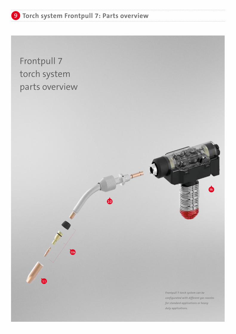
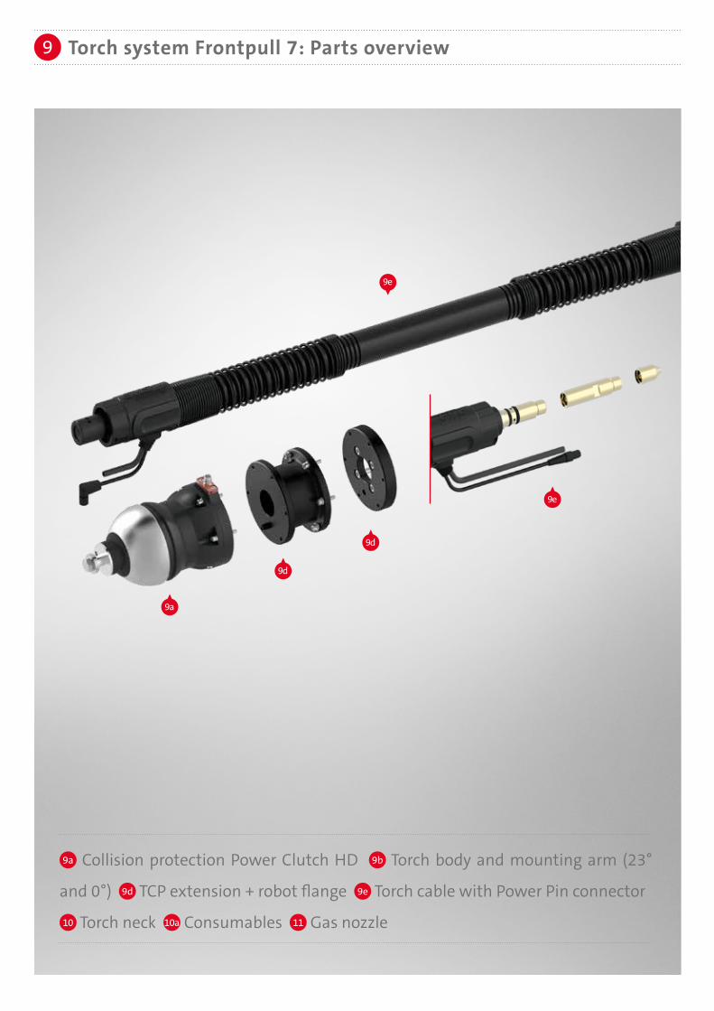
9 Torch system Frontpull 7: Parts overview
Frontpull 7torch system parts overview
Frontpull 7 torch system can be
configurated with different gas nozzles
for standard applications or heavy
duty applications.
9e
9a
9d
9d
9e
Torch system Frontpull 7: Parts overview9
9a Collision protection Power Clutch HD 9b Torch body and mounting arm (23°
and 0°) 9d TCP extension + robot flange 9e Torch cable with Power Pin connector
10 Torch neck 10a Consumables 11 Gas nozzle
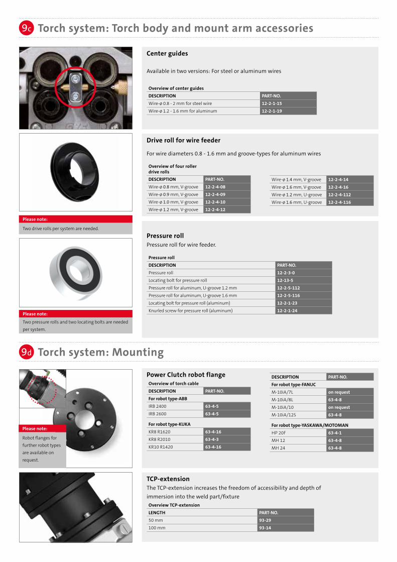
Drive roll for wire feeder
For wire diameters 0.8 - 1.6 mm and groove-types for aluminum wires
Overview of four roller drive rollsDESCRIPTION PART-NO.Wire-ø 0.8 mm, V-groove 12-2-4-08Wire-ø 0.9 mm, V-groove 12-2-4-09Wire-ø 1.0 mm, V-groove 12-2-4-10Wire-ø 1.2 mm, V-groove 12-2-4-12
TCP-extensionThe TCP-extension increases the freedom of accessibility and depth of immersion into the weld part/fixtureOverview TCP-extensionLENGTH PART-NO.50 mm 93-29100 mm 93-14
Torch system: Torch body and mount arm accessories
Torch system: Mounting
9c
9d
Center guides
Available in two versions: For steel or aluminum wires
Overview of center guidesDESCRIPTION PART-NO.Wire-ø 0.8 - 2 mm for steel wire 12-2-1-15Wire-ø 1.2 - 1.6 mm for aluminum 12-2-1-19
Power Clutch robot flange Overview of torch cableDESCRIPTION PART-NO.For robot type-ABBIRB 2400 63-4-5IRB 2600 63-4-5
For robot type-KUKAKR8 R1620 63-4-16KR8 R2010 63-4-3KR10 R1420 63-4-16
Wire-ø 1.4 mm, V-groove 12-2-4-14Wire-ø 1.6 mm, V-groove 12-2-4-16Wire-ø 1.2 mm, U-groove 12-2-4-112Wire-ø 1.6 mm, U-groove 12-2-4-116
DESCRIPTION PART-NO.For robot type-FANUCM-10iA/7L on requestM-10iA/8L 63-4-8M-10iA/10 on requestM-10iA/12S 63-4-8
For robot type-YASKAWA/MOTOMANHP 20F 63-4-1MH 12 63-4-8MH 24 63-4-8
Please note:
Robot flanges for further robot types are available on request.
Please note:
Two drive rolls per system are needed.
Please note:
Two pressure rolls and two locating bolts are needed per system.
Pressure roll Pressure roll for wire feeder.
Pressure rollDESCRIPTION PART-NO.Pressure roll 12-2-3-0Locating bolt for pressure roll 12-13-5Pressure roll for aluminum, U-groove 1.2 mm 12-2-5-112Pressure roll for aluminum, U-groove 1.6 mm 12-2-5-116Locating bolt for pressure roll (aluminum) 12-2-1-23Knurled screw for pressure roll (aluminum) 12-2-1-24

Torch system: Torch cable9e
Connection cable for Frontpull 7 torch
Connection between Frontpull 7 torch and Frontpull module
LENGTH PART-NO.1.0 m 77-2012-101.2 m 77-2012-121.3 m 77-2012-131.5 m 77-2012-15LENGTH PART-NO.
Liner for torch cableFor the following diameters and filler materials:
Steel, bronze (wire-ø 1.2 - 1.6 mm)LENGTH PART-NO.2.0 m 44-22-1216-203.5 m 44-22-1216-35Sleeve for liner 44-30-3
Overview of torch cablesDESCRIPTION PART-NO.0,75 m 61-5-0750.9 m 61-5-091.0 m 61-5-101.2 m 61-5-12
1.5 m 61-5-151.8 m 61-5-182.0 m 61-5-202.4 m 61-5-24
1.8 m 77-2012-182.1 m 77-2012-212.3 m 77-2012-232.7 m 77-2012-27
Overview connection cables
Please note:Length connection cable = torch cable length + 0.3m
Aluminum (wire-ø 1.2 - 1.6 mm)per meter 91-68-47025-25Sleeve for liner 44-30-7Sleeve for torch system 10-5-29Power Pin cap 61-2-0-2-7
Power Pin extension 61-2-0-2-5
Velcro® tape formounting (10 pcs.) 571040310
Torch cable
High flexible coaxial cable 72 mm2 with Power Pin and torch connector including switch-off cable for the robot. Additionally the Power Pin extension is required.
Overview recommended torch cable lengths for robots
DESCRIPTION PART-NO.For robot type-ABBIRB 2400 (0.9 m) 61-5-09IRB 2600 (1.0 m) 61-5-10
For robot type-KUKAKR8 R1620 (0.9 m) 61-5-09KR8 R2010 (1.2 m) 61-5-12KR10 R1420 (.9 m) 61-5-09
DESCRIPTION PART-NO.For robot type-FANUCM10iA/7L on requestM10iA/8L on requestM10iA/12 (0.9 m) 61-5-09M10iA/12S on request
For robot type-YASKAWA/MOTOMANHP 20F (1.0 m) 61-5-10MH 12 (1.0 m) 61-5-10MH 24 (1.0 m) 61-5-10
wire guidance for torch neckSteel, bronzeDESCRIPTION PART-NO.Frontpull wire guidance (white) for torch neck, Wire-ø 0.8 mm 58-4-11-500-08Frontpull wire guidance (white) for torch neck, Wire-ø 0.9 – 1.0 mm 58-4-11-500-10Frontpull wire guidance (red) for torch neck, Wire-ø 1.2 mm 58-4-11-500-12Frontpull wire guidance (red) for torch neck, Wire-ø 1.4 – 1.6 mm 58-4-11-500-16
AluminumDESCRIPTION PART-NO.Frontpull Wire guidance for aluminum wire ø 1.2 – 1.6 mm 58-4-10-500Inset FP8i for Wire guidance aluminum wire ø 1.2 – 1.6 mm 44-30-17

SKS offers a special torch neck (up to 250 A, ZK-HeavyDuty up to max. 300 A) for welding components with tight accessibility.The special torch neck needs a smaller insulator (ZK) and a more compact gas nozzle (ZK). Standard Power Lock contact tips can be used.
TCP drawings can be found on the next to last page (torch necks).
Torch necks for Frontpull 7
With the innovative bayonet lock system, the SKS torch neck can be replaced quickly. This unique tool-free quick change system is also highly precise with TCP accuracy of ± 0.2 mm.
Application recommendationsOverview torch necks Frontpull 7 – 23° version Frontpull 7 – 0° versionType PART-NO. angle [°] TCP length [mm] Steel/CrNi Al* TCP length [mm] Steel/CrNi Al*
stan
dard
dre
ssin
g ai
r-co
oled
58-1-00-400-1 0 583.6 √ √ 611.5 √ √58-1-22-350-1 22 520.0 √ √ √ √ 561.5 √ √58-1-22-400-1 22 566.0 √ √ 611.5 √ √58-4-330-500-1 30 on request O O 650.0 O O58-1-130-450-1 30 on request O O 661.5 O O58-1-35-400-1 35 on request X X 611.5 √ X58-1-45-350-1 45 on request X X 561.5 √ X58-1-45-400-1 45 on request X X 611.5 √ X58-1-45-450-1 45 on request X X 661.5 √ X58-4-345-450-1 45 on request X X 600.0 √ √ √ √58-4-345-567-1 45 on request X X 717.0 √ √
Type PART-NO. angle [°] TCP length [mm] Steel/CrNi Al TCP length [mm] Steel/CrNi AlZK 58-1-245-400-1 45 on request X X 561.5 √ X
√ √ Recommended standard torch neck√ RecommendedO Special design: application specificX Not recommended
Clamping cap for SKS single wire torch necksTool-free assembly with bayonet quick-change system Clamping capDESCRIPTION PART-NO.Clamping cap 71-3-25
Torches: Torch necks/Accessories10
INFO: TORCH NECK
ZK TYPE
Insulator for SKS torch necks
Overview insulatorDESCRIPTION PART-NO.Standard 58-1-5ZK type 43-6-4-2ZK heavy duty type 43-6-4-3
* Please note:
For aluminum applicationsSKS recommends a Frontpull torch system

HQX Torch necks for Frontpull 7Version Frontpull 7 – 23° Version Frontpull 7 – 0°
Overview torch necksApplication recommendations
Application recommendations
Type PART-NO. angle [°] TCP length [mm] Steel/CrNi Al* TCP length
[mm] Steel/CrNi Al*
HQ
X-dr
essi
ng
air-
cool
ed
58-1-622-350-1 22 520.0 √ √ √ √ 561.5 √ √58-1-622-400-1 22 566.0 √ √ 611.5 √ √58-1-635-400-1 35 on request X X 611.5 √ √58-1-645-350-1 45 on request X X 561.5 √ √58-1-645-400-1 45 on request X X 611.5 √ √58-4-6345-450-1 45 on request X X 600.0 √ √ √ √58-4-6345-567-1 45 on request X X 717.0 √ √
√ √ Recommended standard torch neck√ RecommendedO Special design: application specificX Not recommended
* Please note:
For aluminum applicationsSKS recommends a Frontpull torch system
Insulator for SKS torch necksInsulatorDESCRIPTION PART-NO.HQX Insulator for single wire torch necks 58-1-14
Power Lock: Contact tips
• Tapered design for high TCP reproducibility• Improved heat transfer extends lifetime• Improved power transition: constant arc qualityOverview of contact tips (also for ZK type)Wire-ø Steel applications Stainless steel applications Aluminum applications
Power Lock Power Lock Plus Power Lock Power Lock Plus Power Lock Power Lock Plus0.8 mm 40-4-5-0.8E 40-6-5-0.8E 40-4-7-0.8S 40-6-7-0.8S –––––––––– ––––––––––0.9 mm 40-4-5-0.9E 40-6-5-0.9E 40-4-7-0.9S 40-6-7-0.9S –––––––––– ––––––––––1.0 mm 40-4-5-1.0E 40-6-5-1.0E 40-4-7-1.0S 40-6-7-1.0S –––––––––– ––––––––––1.2 mm 40-4-5-1.2E 40-6-5-1.2E 40-4-7-1.2S 40-6-7-1.2S 40-4-7-1.2AL 40-6-7-1.2AL1.4 mm –––––––––– –––––––––– 40-4-7-1.4S 40-6-7-1.4S –––––––––– ––––––––––1.6 mm –––––––––– –––––––––– 40-4-7-1.6S 40-6-7-1.6S 40-4-7-1.6AL 40-6-7-1.6AL
Torches: Consumables10a
Please note:An overview of gas nozzles with dimensions canbe found on the next pages.
HQX Torches: Torch necks/Accessories10
Lock: Retaining headRetaining heads for heavy duty applications with thread for threaded gas nozzles for simple and safe installationOverview of retaining headsDESCRIPTION PART-NO.High performance retaining head Power Lock standard 43-9-2High performance retaining head Power Lock with 6 holes (AL-application) 43-9-4High performance retaining head HQX Power Lock Plus with 6 holes (Fe-/Al-application) 43-20-3High performance retaining head Power Lock (ZK-Version) 43-8-6High performance retaining head Power Lock Plus 43-16-2High performance retaining head Power Lock Plus (ZK-Version) 43-24-1

Torches: Consumables10a10a
Please note:An overview of gas nozzles with dimensions canbe found on the next page.
Please note:
Further information can be found in our brochure "Consumables" (DOC-0135EN).
Heavy Duty gas nozzles13 mm PART-NO.flush, bottle shaped 41-20-13-BFlong, tapered 41-20-13-TR16 mm tapered PART-NO.short 41-20-16-TSflush 41-20-16-TFlong 41-20-16-TR
ZK type13 mm bottle shaped PART-NO.short 41-21-13-BSflush 41-21-13-BF15 mm bottle shaped PART-NO.short 41-21-15-BSflush 41-21-15-BF13+15 mm Heavy Duty/tapered PART-NO.13 mm, flush 41-22-13-TF15 mm, flush 41-22-15-TF
Tool for contact tips
For replacement of contact tips: Fast exchange of contact tip without removing the gas nozzlecontact tipsDESCRIPTION PART-NO.Mounting tool SW6 for contact tips (Power Lock) 51-9001-00Mounting tool SW7 for contact tips (Power Lock Plus) 51-9002-00
Programming tips
Power Lock programming tips for precise seam programming
Overview of programming tipsStickout PART-NO.12 mm (Power Lock) 65-615 mm (Power Lock) 65-720 mm (Power Lock) 65-812 mm (Power Lock Plus) 65-1115 mm (Power Lock Plus) 65-12
Gas nozzles with thread (HQX)HQX gas nozzles16 mm bottle shaped PART-NO.short 41-16-16-BS16 mm tapered PART-NO.short 41-16-16-TSflush 41-16-16-TFlong 41-16-16-TR
Gas nozzles with threadStandard gas nozzles 13 mm bottle shaped PART-NO.short 41-19-13-BSflush 41-19-13-BFlong 41-19-13-BR13 mm tapered PART-NO.short 41-19-13-TSflush 41-19-13-TFlong 41-19-13-TR15 mm bottle shaped PART-NO.short 41-19-15-BSflush 41-19-15-BFlong 41-19-15-BR16 mm tapered PART-NO.short 41-19-16-TSflush 41-19-16-TF
long 41-19-16-TR

Gas nozzle PART-NO. 41-21-13-BS 41-21-13-BF Reamer Blade: Power Lock (UNF 3/8“ x 24) PART-NO. 66-13-ZK-S 66-13-ZK-F (M10 x 1) eReam PART-NO. 67-13-S 67-13-F Power Lock Plus (UNF 3/8“ x 24) PART-NO. 68-13-ZK-S 68-13-ZK-F (M10 x 1) eReam PART-NO. 69-13-S 69-13-F
41-21-15-BS 41-21-15-BF
66-15-ZK-S 66-15-ZK-F 67-15-ZK-S 67-15-ZK-F
68-15-ZK-S 68-15-ZK-F 69-15-ZK-S 69-15-ZK-F
41-22-13-TF 41-22-15-TF
66-13-ZK-F 66-15-ZK-F 67-13-F 67-15-ZK-F
68-15-ZK-F 68-15-ZK-F 69-15-F 69-15-ZK-F
Gas nozzles: Overview dimensions11
Dimensions in mm.
Further gas nozzles, reamer blades and torch necks can be found in our consumables brochure.
13 mm bottle-shaped 13+15 mm Heavy Duty/tapered15 mm bottle-shapedZK type:
Gas nozzle PART-NO. 41-19-13-BS 41-19-13-BF 41-19-13-BR Reamer Blade: Power Lock (UNF 3/8“ x 24) PART-NO. 66-13-S 66-13-F 66-13-R (M10 x 1) eReam PART-NO. 67-13-S 67-13-F 67-13-R Power Lock Plus (UNF 3/8“ x 24) PART-NO. 68-13-S 68-13-F 68-13-R (M10 x 1) eReam PART-NO. 69-13-S 69-13-F 69-13-R
41-19-16-TS 41-19-16-TF 41-19-16-TR
66-16-S 66-16-F 66-16-R 67-16-S 67-16-F 67-16-R
68-16-S 68-16-F 68-16-R 69-16-S 69-16-F 69-16-R
41-20-16-TS 41-20-16-TF 41-20-16-TR
66-16-S 66-16-F 66-16-R 67-16-S 67-16-F 67-16-R
68-16-S 68-16-F 68-16-R 69-16-S 69-16-F 69-16-R
13 mm bottle-shaped
16 mm tapered
13 mm tapered
15 mm bottle-shaped
13 mm Heavy Duty
16 mm Heavy Duty
41-19-13-BS 41-19-13-BF 41-19-13-BR
41-19-13-TS 41-19-13-TF 41-19-13-TR
66-13-S 66-13-F 66-13-R 67-13-S 67-13-F 67-13-R
68-13-S 68-13-F 68-13-R 69-13-S 69-13-F 69-13-R
41-20-13-BF 41-20-13-TR
66-13-F 66-13-R 67-13-F 67-13-R
68-13-F 68-13-R 69-13-F 69-13-R
41-19-13-TS 41-19-13-TF 41-19-13-TR 41-20-13-BF 41-20-13-TR
41-20-16-TR41-20-16-TF41-20-16-TS41-19-16-TR41-19-16-TF41-19-16-TS
41-21-13-BS 41-21-13-BF 41-21-15-BS 41-21-15-BF 41-22-13-TF 41-22-15-TF
Gas nozzle PART-NO. 41-19-15-BS 41-19-15-BF 41-19-15-BR Reamer Blade: Power Lock (UNF 3/8“ x 24) PART-NO. 66-15-S 66-15-F 66-15-R (M10 x 1) eReam PART-NO.. 67-15-S 67-15-F 67-15-R Power Lock Plus (UNF 3/8“ x 24) PART-NO. 68-15-S 68-15-F 68-15-R (M10 x 1) eReam PART-NO. 69-15-S 69-15-F 69-15-R
41-19-15-BR41-19-15-BF41-19-15-BS

Please note:Dimensions in mm.
Gas nozzles: Reamer blades11a
Reamer blade (internal thread UNF 3/8“ x 24) Reamer blade short flush longInner diameter of the gas nozzle PART-NO. PART-NO. PART-NO.13 mm 66-13-S 66-13-F 66-13-R15 mm 66-15-S 66-15-F 66-15-R16 mm 66-16-S 66-16-F 66-16-R
DimensionsA B C D E F PART-NO.
44 - 67 12.5 9 - 66-13-S44 - 70 12.5 9 - 66-13-F44 - 73 12.5 9 - 66-13-R
45 68 85 14.5 11.8 9 66-15-S45 71 88 14.5 11.8 9 66-15-F45 74 91 14.5 11.8 9 66-15-R
45 68 85 15.5 11.8 9 66-16-S45 71 88 15.5 11.8 9 66-16-F45 74 91 15.5 11.8 9 66-16-R
Standard torch neck – Power Lock
Gas nozzles: Overview dimensions11
Gas nozzle PART-NO. 41-16-16-BS Reamer Blade: Power Lock Plus (UNF 3/8“ x 24) PART-NO. 68-16-HD-S (M10 x 1) eReam PART-NO. 69-16-HD-S
HQX Version
Dimensions in mm.
Further gas nozzles, reamer blades and torch necks can be found in our consumables brochure.
16 mm bottle-shaped 16 mm tapered
41-16-16-TS 41-16-16-TF 41-16-16-TR 68-16-HD-S 68-16-HD-F 68-16-HD-R 69-16-HD-S 69-16-HD-F 68-16-HD-R
41-16-16-BS 41-16-16-TS 41-16-16-TF 41-16-16-TR

Please note:Dimensions in mm.
Reamer blade (internal thread M10 x 1 – eReam)
Reamer blade short flush longInner diameter of the gas nozzle PART-NO. PART-NO. PART-NO.13 mm 67-13-S 67-13-F 67-13-R15 mm 67-15-S 67-15-F 67-15-R16 mm 67-16-S 67-16-F 67-16-R
DimensionsA B C D E F PART-NO.
55 - 78 12.5 9 - 67-13-S55 - 81 12.5 9 - 67-13-F55 - 84 12.5 9 - 67-13-R
38 61 78 14.5 11.8 9 67-15-S38 64 81 14.5 11.8 9 67-15-F38 67 84 14.5 11.8 9 67-15-R
38 61 78 15.5 11.8 9 67-16-S38 64 81 15.5 11.8 9 67-16-F38 67 84 15.5 11.8 9 67-16-R
Reamer blade (internal thread UNF 3/8“ x 24)Reamer blade short flush longInner diameter of the gas nozzle PART-NO. PART-NO. PART-NO.13 mm 68-13-S 68-13-F 68-13-R15 mm 68-15-S 68-15-F 68-15-R16 mm 68-16-S 68-16-F 68-16-R
DimensionsA B C D E F PART-NO.
55.5 - 67 12.5 9 - 68-13-S52.5 - 67 12.5 9 - 68-13-F49.5 - 67 12.5 9 - 68-13-R
51 63 91 14.5 11.8 9 68-15-S48 63 91 14.5 11.8 9 68-15-F45 63 91 14.5 11.8 9 68-15-R
51 63 91 15.5 11.8 9 68-16-S48 63 91 15.5 11.8 9 68-16-F45 63 91 15.5 11.8 9 68-16-R
Standard torch neck – Power Lock Plus
Gas nozzles: Reamer blades11a
Standard torch neck – Power Lock
Reamer blade (internal thread M10 x 1 – eReam)
Reamer blade short flush longInner diameter of the gas nozzle PART-NO. PART-NO. PART-NO.13 mm 69-13-S 69-13-F 69-13-R15 mm 69-15-S 69-15-F 69-15-R16 mm 69-16-S 68-16-F 68-16-R
DimensionsA B C D E F PART-NO.
66.5 - 78 12.5 9 - 69-13-S66.5 - 81 12.5 9 - 69-13-F66.5 - 84 12.5 9 - 69-13-R
38 50 78 14.5 11.8 9 69-15-S38 53 81 14.5 11.8 9 69-15-F38 56 84 14.5 11.8 9 69-15-R
38 50 78 15.5 11.8 9 69-16-S38 53 81 15.5 11.8 9 69-16-F38 56 84 15.5 11.8 9 69-16-R

Gas nozzles: Reamer blades11a
Reamer blade (internal thread UNF 3/8“ x 24)
Reamer blade short flush longInner diameter of the gas nozzle PART-NO. PART-NO. PART-NO.13 mm 66-13-ZK-S 66-13-ZK-F -15 mm 66-15-ZK-S 66-15-ZK-F -
DimensionsA B C D E F PART-NO.
54 - 77 12.5 9 - 66-13-ZK-S51 - 77 12.5 9 - 66-13-ZK-F
45 68 77 14.5 11.8 9 66-15-ZK-S42 68 77 14.5 11.8 9 66-15-ZK-F
ZK-Series – Power Lock
Reamer blade (internal thread M10 x 1 – eReam)
Reamer blade short flush longInner diameter of the gas nozzle PART-NO. PART-NO. PART-NO.13 mm 67-13- S 67-13-F -15 mm 67-15-ZK-S 67-15-ZK-F -
DimensionsA B C D E F PART-NO.
55 - 78 12.5 9 - 67-13-S55 - 81 12.5 9 - 67-13-F
46 69 78 14.5 11.8 9 67-15-ZK-S46 72 81 14.5 11.8 9 67-15-ZK-F
Please note:Dimensions in mm.
Reamer blade (internal thread UNF 3/8“ x 24) Reamer blade short flush longInner diameter of the gas nozzle PART-NO. PART-NO. PART-NO.13 mm 68-13-ZK-S 68-13-ZK-F -15 mm 68-15-ZK-S 68-15-ZK-F -
DimensionsA B C D E F PART-NO.
65.5 - 77 12.5 9 - 68-13-ZK-S62.5 - 77 12.5 9 - 68-13-ZK-F
45 58 77 14.5 11.8 9 68-15-ZK-S42 58 77 14.5 11.8 9 68-15-ZK-F
ZK-Series – Power Lock Plus

Gas nozzles: Reamer blades11a
Reamer blade (internal thread UNF 3/8“ x 24)
Reamer blade short flush longInner diameter of the gas nozzle PART-NO. PART-NO. PART-NO.16 mm 68-16-HD-S 68-16-HD-F 68-16-HD-R
DimensionsA B C D E F PART-NO.
49.5 62 85 15.5 12.8 9 68-16-HD-S46.5 62 85 15.5 12.8 9 68-16-HD-F43.5 62 85 15.5 12.8 9 68-16-HD-R
HQX-Series – Power Lock Plus
Please note:Dimensions in mm.
Reamer blade (internal thread M10 x 1 – eReam)
Reamer blade short flush longInner diameter of the gas nozzle PART-NO. PART-NO. PART-NO.13 mm 69-13- S 69-13-F -15 mm 69-15-ZK-S 69-15-ZK-F -
DimensionsA B C D E F PART-NO.
66.5 - 78 12.5 9 - 69-13-S66.5 - 81 12.5 9 - 69-13-F
46 59 78 14.5 11.8 9 69-15-ZK-S46 62 81 14.5 11.8 9 69-15-ZK-F
ZK-Series – Power Lock Plus
Reamer blade (internal thread M10 x 1 – eReam)
Reamer blade short flush longInner diameter of the gas nozzle PART-NO. PART-NO. PART-NO.16 mm 69-16-HD-S 69-16-HD-F 69-16-HD-R
DimensionsA B C D E F PART-NO.
38 50.5 73.5 15.5 12.8 9 69-16-HD-S38 53.5 76.5 15.5 12.8 9 69-16-HD-F38 56.5 79.5 15.5 12.8 9 69-16-HD-R
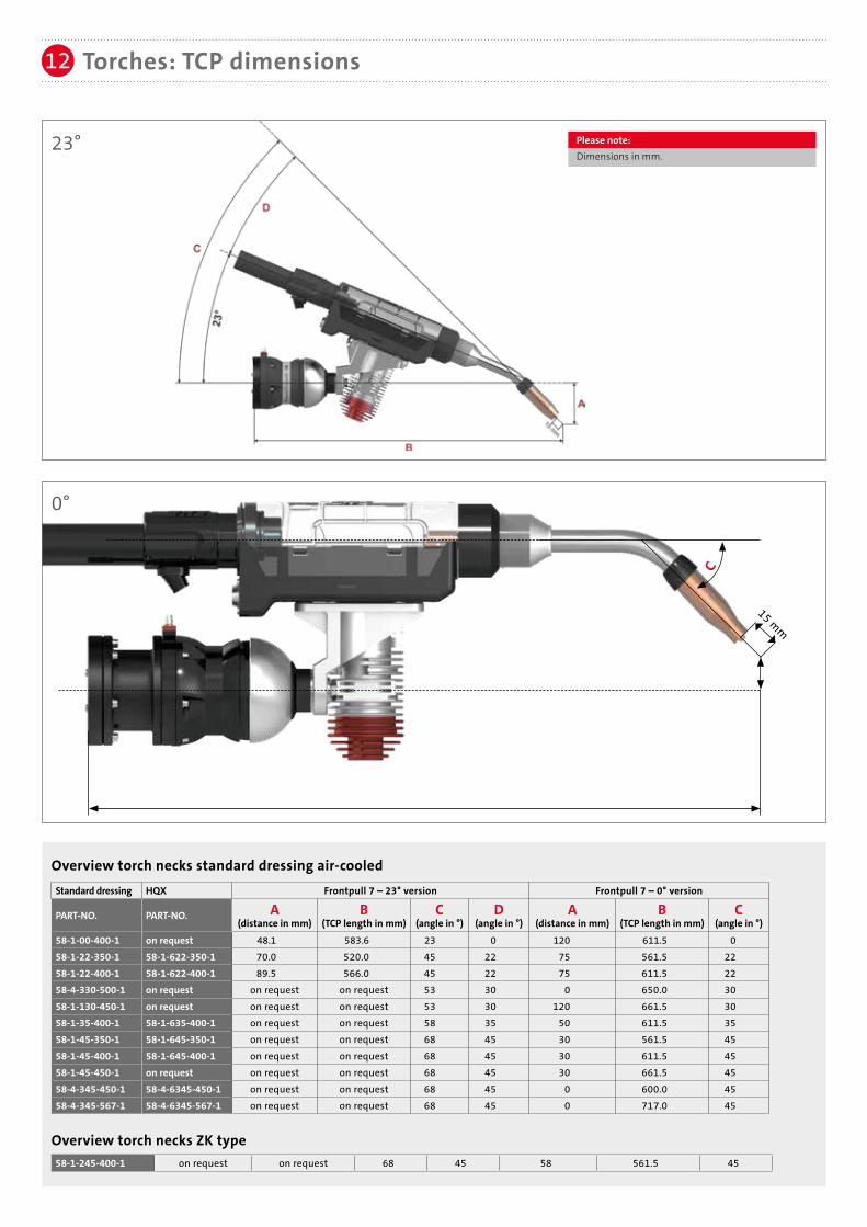
Torches: TCP dimensions12
C
15 mm
Standard dressing HQX Frontpull 7 – 23° version Frontpull 7 – 0° version
PART-NO. PART-NO. A (distance in mm)
B (TCP length in mm)
C (angle in °)
D (angle in °)
A (distance in mm)
B (TCP length in mm)
C (angle in °)
58-1-00-400-1 on request 48.1 583.6 23 0 120 611.5 058-1-22-350-1 58-1-622-350-1 70.0 520.0 45 22 75 561.5 2258-1-22-400-1 58-1-622-400-1 89.5 566.0 45 22 75 611.5 2258-4-330-500-1 on request on request on request 53 30 0 650.0 3058-1-130-450-1 on request on request on request 53 30 120 661.5 3058-1-35-400-1 58-1-635-400-1 on request on request 58 35 50 611.5 3558-1-45-350-1 58-1-645-350-1 on request on request 68 45 30 561.5 4558-1-45-400-1 58-1-645-400-1 on request on request 68 45 30 611.5 4558-1-45-450-1 on request on request on request 68 45 30 661.5 4558-4-345-450-1 58-4-6345-450-1 on request on request 68 45 0 600.0 4558-4-345-567-1 58-4-6345-567-1 on request on request 68 45 0 717.0 45
58-1-245-400-1 on request on request 68 45 58 561.5 45
Overview torch necks standard dressing air-cooled
Overview torch necks ZK type
0°
23° Please note:Dimensions in mm.

To check TCP of torch necks and complete torch.
Checking fixtures are provided for all listed torch necks with Frontpull 7 torch system. Please contact us for detailed information.
Torches: Checking fixtures12a
Top view checking fixture
Pure Electric.For a precise and regulated
cleaning of the torch
frontend
For further information
please visit
www.eReam.de
Please note:
Further iInformation can be found in our brochure "Checking fixtures" (DOC-0137EN).
Please note:
Further iInformation can be found in our eReam brochure (DOC-0184EN).

Subject to change.
SKS Welding Systems GmbH | Marie-Curie-Strasse 14 | 67661 Kaiserslautern | [email protected] | www.sks-welding.com


