
1-40 3268
12-12
2004 Specifications
SPECIAL SPECIFICATION
3268
Dense-Graded Hot-Mix Asphalt
1. Description. Construct a hot-mix asphalt (HMA) pavement layer composed of a compacted,
dense-graded mixture of aggregate and asphalt binder mixed hot in a mixing plant. Pay
adjustments will apply to HMA placed under this specification unless the HMA is deemed
exempt in accordance with Section 3268.4.I.4, “Exempt Production.”
2. Materials. Furnish uncontaminated materials of uniform quality that meet the requirements
of the plans and specifications.
Notify the Engineer of all material sources. Notify the Engineer before changing any
material source or formulation. When the Contractor makes a source or formulation change,
the Engineer will verify that the specification requirements are met and may require a new
laboratory mixture design, trial batch, or both. The Engineer may sample and test project
materials at any time during the project to verify specification compliance in accordance
with Item 6, “Control of Materials.”
A. Aggregate. Furnish aggregates from sources that conform to the requirements shown in
Table 1 and as specified in this Section. Aggregate requirements in this Section,
including those shown in Table 1, may be modified or eliminated when shown on the
plans. Additional aggregate requirements may be specified when shown on the plans.
Provide aggregate stockpiles that meet the definitions in this Section for coarse,
intermediate, or fine aggregate. Aggregate from reclaimed asphalt pavement (RAP) is
not required to meet Table 1 requirements unless otherwise shown on the plans. Supply
aggregates that meet the definitions in Tex-100-E for crushed gravel or crushed stone.
The Engineer will designate the plant or the quarry as the sampling location. Samples
must be from materials produced for the project. The Engineer will establish the surface
aggregate classification (SAC) and perform Los Angeles abrasion, magnesium sulfate
soundness, and Micro-Deval tests. Perform all other aggregate quality tests listed in
Table 1. Document all test results on the mixture design report. The Engineer may
perform tests on independent or split samples to verify Contractor test results. Stockpile
aggregates for each source and type separately. Determine aggregate gradations for
mixture design and production testing based on the washed sieve analysis given in
Tex-200-F, Part II.
1. Coarse Aggregate. Coarse aggregate stockpiles must have no more than 20%
material passing the No. 8 sieve. Aggregate from sources listed in the Department’s
Bituminous Rated Source Quality Catalog (BRSQC) located at
http://www.txdot.gov/business/resources/producer-list.html are preapproved for
use.
2-40 3268
12-12
For sources not listed on the Department’s BRSQC:
build an individual stockpile for each material;
request the Department test the stockpile for specification compliance; and
once approved, do not add material to the stockpile unless otherwise approved.
Use only the rated values for hot mix listed in the BRSQC. Rated values for surface
treatment (ST) do not apply to coarse aggregate sources used in hot mix. Provide
aggregate from non-listed sources only when tested by the Engineer and approved
before use. Allow 30 calendar days for the Engineer to sample, test, and report
results for non-listed sources.
Provide coarse aggregate with at least the minimum SAC as shown on the plans.
SAC requirements apply only to aggregates used on the surface of travel lanes.
SAC requirements apply to aggregates used on surfaces other than travel lanes
when shown on the plans. The SAC for sources on the Department’s Aggregate
Quality Monitoring Program (AQMP) is listed in the BRSQC.
a. Blending Class A and Class B Aggregates. Class B aggregate meeting all
other requirements in Table 1 may be blended with a Class A aggregate in
order to meet requirements for Class A materials. When blending Class A and
B aggregates to meet a Class A requirement, ensure that at least 50% by weight
of the material retained on the No. 4 sieve comes from the Class A aggregate
source. Blend by volume if the bulk specific gravities of the Class A and B
aggregates differ by more than 0.300. For blending purposes, coarse aggregate
from RAP and Recycled Asphalt Shingles (RAS) will be considered as Class B
aggregate.
When the Contractor blends Class A and B aggregates to meet a Class A
requirement, the Engineer may perform tests at any time during production to
ensure that at least 50% by weight of the material retained on the No. 4 sieve
comes from the Class A aggregate source. In such cases where the Engineer
elects to verify conformance, the Engineer will use the Department’s mix
design Excel template to calculate the percent of Class A aggregate retained on
the No. 4 sieve by inputting the bin percentages shown from readouts in the
control room at the time of production and stockpile gradations measured at
the time of production. The Engineer may determine the gradations based on
either washed or dry sieve analysis from samples obtained from individual
aggregate cold feed bins or aggregate stockpiles. The Engineer may perform
spot checks using the gradations supplied by the Contractor on the mixture
design report as an input for the Excel template; however, a failing spot check
will require confirmation with a stockpile gradation determined by the
Engineer.
b. Micro-Deval Abrasion. The Engineer will perform a minimum of one Micro-
Deval abrasion test in accordance with Tex-461-A for each coarse aggregate
source used in the mixture design that has a Rated Source Soundness
3-40 3268
12-12
Magnesium (RSSM) loss value greater than 15 as listed in the BRSQC. The
Engineer will perform testing prior to the start of production and may perform
additional testing at any time during production. The Engineer may obtain the
coarse aggregate samples from each coarse aggregate source or may require
the Contractor to obtain the samples. The Engineer may elect to waive all
Micro-Deval testing based on a satisfactory test history of the same aggregate
source.
When tested, the Engineer will estimate the magnesium sulfate soundness loss
for each coarse aggregate source using the following formula:
Mgest. = (RSSM)(MDact./RSMD)
where:
Mgest = magnesium sulfate soundness loss
MDact = actual Micro-Deval percent loss
RSMD = Rated Source Micro-Deval
When the estimated magnesium sulfate soundness loss is greater than the
maximum magnesium sulfate soundness loss specified, the coarse aggregate
source will not be allowed for use unless otherwise approved by the Engineer.
The Engineer will consult the Geotechnical, Soils, and Aggregates Branch of
the Construction Division, and additional testing may be required prior to
granting approval.
2. Intermediate Aggregate. Aggregates not meeting the definition of coarse or fine
aggregate will be defined as intermediate aggregate. When used, supply
intermediate aggregates that are free from organic impurities. The Engineer may
test the intermediate aggregate in accordance with Tex-408-A to verify the material
is free from organic impurities. When used, supply intermediate aggregate from
coarse aggregate sources that meet the requirements shown in Table 1 unless
otherwise approved.
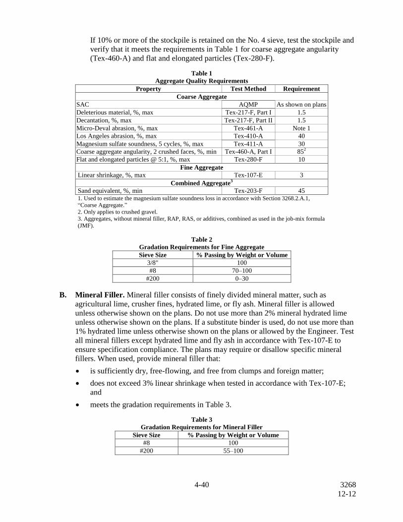
If 10% or more of the stockpile is retained on the No. 4 sieve, test the stockpile and
verify that it meets the requirements in Table 1 for coarse aggregate angularity
(Tex-460-A) and flat and elongated particles (Tex-280-F).
3. Fine Aggregate. Fine aggregates consist of manufactured sands, screenings, and
field sands. Fine aggregate stockpiles must meet the gradation requirements in
Table 2. Supply fine aggregates that are free from organic impurities. The Engineer
may test the fine aggregate in accordance with Tex-408-A to verify the material is
free from organic impurities. At most 15% of the total aggregate may be field sand
or other uncrushed fine aggregate. With the exception of field sand, use fine
aggregate from coarse aggregate sources that meet the requirements shown in
Table 1 unless otherwise approved.
4-40 3268
12-12
If 10% or more of the stockpile is retained on the No. 4 sieve, test the stockpile and
verify that it meets the requirements in Table 1 for coarse aggregate angularity
(Tex-460-A) and flat and elongated particles (Tex-280-F).
Table 1
Aggregate Quality Requirements
Property Test Method Requirement
Coarse Aggregate
SAC AQMP
As shown on plans
Deleterious material, %, max Tex-217-F, Part I 1.5
Decantation, %, max Tex-217-F, Part II 1.5
Micro-Deval abrasion, %, max Tex-461-A Note 1
Los Angeles abrasion, %, max Tex-410-A 40
Magnesium sulfate soundness, 5 cycles, %, max Tex-411-A 30
Coarse aggregate angularity, 2 crushed faces, %, min Tex-460-A, Part I 852
Flat and elongated particles @ 5:1, %, max Tex-280-F 10
Fine Aggregate
Linear shrinkage, %, max Tex-107-E 3
Combined Aggregate3
Sand equivalent, %, min Tex-203-F 45 1. Used to estimate the magnesium sulfate soundness loss in accordance with Section 3268.2.A.1,
“Coarse Aggregate.”
2. Only applies to crushed gravel.
3. Aggregates, without mineral filler, RAP, RAS, or additives, combined as used in the job-mix formula
(JMF).
Table 2
Gradation Requirements for Fine Aggregate
Sieve Size % Passing by Weight or Volume
3/8" 100
#8
70–100
#200 0–30
B. Mineral Filler. Mineral filler consists of finely divided mineral matter, such as
agricultural lime, crusher fines, hydrated lime, or fly ash. Mineral filler is allowed
unless otherwise shown on the plans. Do not use more than 2% mineral hydrated lime
unless otherwise shown on the plans. If a substitute binder is used, do not use more than
1% hydrated lime unless otherwise shown on the plans or allowed by the Engineer. Test
all mineral fillers except hydrated lime and fly ash in accordance with Tex-107-E to
ensure specification compliance. The plans may require or disallow specific mineral
fillers. When used, provide mineral filler that:
is sufficiently dry, free-flowing, and free from clumps and foreign matter;
does not exceed 3% linear shrinkage when tested in accordance with Tex-107-E;
and
meets the gradation requirements in Table 3.
Table 3
Gradation Requirements for Mineral Filler
Sieve Size % Passing by Weight or Volume
#8 100
#200 55–100
5-40 3268
12-12
C. Baghouse Fines. Fines collected by the baghouse or other dust-collecting equipment
may be reintroduced into the mixing drum.
D. Asphalt Binder. Furnish the type and grade of performance-graded (PG) asphalt
specified on the plans.
E. Tack Coat. Furnish CSS-1H, SS-1H, or a PG binder with a minimum high-temperature
grade of PG 58 for tack coat binder in accordance with Item 300, “Asphalts, Oils, and
Emulsions.” Specialized or preferred tack coat materials may be allowed by the
Engineer or required when shown on the plans. Do not dilute emulsified asphalts at the
terminal, in the field, or at any other location before use.
The Engineer will obtain at least one sample of the tack coat binder per project in
accordance with Tex-500-C, Part III, and test it to verify compliance with Item 300. The
Engineer will obtain the sample from the asphalt distributor immediately before use.
F. Additives. Use the type and rate of additive specified when shown on the plans. Other
additives that facilitate mixing, compaction, or improve the quality of the mixture may
be allowed when approved. Provide the Engineer with documentation such as the bill of
lading showing the quantity of additives used in the project unless otherwise directed.
1. Lime and Liquid Antistripping Agent. When lime or a liquid antistripping agent
is used, add in accordance with Item 301, “Asphalt Antistripping Agents.” Do not
add lime directly into the mixing drum of any plant where lime is removed through
the exhaust stream unless the plant has a baghouse or dust collection system that
reintroduces the lime into the drum.
2. Warm Mix Asphalt (WMA). Warm Mix Asphalt (WMA) is defined as HMA that
is produced within a target temperature discharge range of 215ºF and 275ºF using
Department-approved WMA additives or processes. The Department’s Material
Producer List of WMA additives and processes is located at
http://www.txdot.gov/business/resources/producer-list.html.
WMA is allowed for use on all projects and is required when shown on plans. The
maximum placement or target discharge temperature for WMA may be set at a
value less than 275ºF when shown on the plans.
Department-approved WMA additives or processes may be used to facilitate
mixing and compaction of HMA produced at target discharge temperatures greater
than 275ºF; however, such mixtures will not be defined as WMA.
G. Recycled Materials. Use of RAP and RAS is permitted unless otherwise shown on the
plans. Do not exceed the maximum allowable percentages of RAP and RAS shown in
Table 4. The allowable percentages shown in Table 4 may be decreased or increased
when shown on the plans. Determine asphalt content and gradation of the RAP and
RAS stockpiles for mixture design purposes in accordance with Tex-236-F. The
Engineer may verify the asphalt content of the stockpiles at any time during production.
Perform other tests on RAP and RAS when shown on the plans. Asphalt binder from
RAP and RAS is designated as recycled asphalt binder. When RAP or RAS is used,
calculate and ensure that the ratio of the recycled asphalt binder to total binder does not
6-40 3268
12-12
exceed the percentages shown in Table 5 during mixture design and HMA production.
During HMA production, use a separate cold feed bin for each stockpile of RAP and
RAS.
Surface, intermediate, and base mixes referenced in Tables 4 and 5 are defined as
follows:
"Surface" mixes are the final lift or riding surface of the pavement structure;
"Intermediate" mixes are non-surface mixtures placed less than or equal to
8 inches from the riding surface; and
"Base" mixes are non-surface mixtures placed greater than 8 inches from the
riding surface.
1. RAP. RAP is salvaged, milled, pulverized, broken, or crushed asphalt pavement.
Crush or break RAP so that 100% of the particles pass the 2 in. sieve.
Use of Contractor-owned RAP including HMA plant waste is permitted unless
otherwise shown on the plans. Department-owned RAP stockpiles are available for
the Contractor’s use when the stockpile locations are shown on the plans. If
Department-owned RAP is available for the Contractor’s use, the Contractor may
use Contractor-owned fractionated RAP and replace it with an equal quantity of
Department-owned RAP. This allowance does not apply to a Contractor using
unfractionated RAP. Department-owned RAP generated through required work on
the Contract is available for the Contractor’s use when shown on the plans. Perform
any necessary tests to ensure Contractor- or Department-owned RAP is appropriate
for use. The Department will not perform any tests or assume any liability for the
quality of the Department-owned RAP unless otherwise shown on the plans. The
Contractor will retain ownership of RAP generated on the project when shown on
the plans.
Fractionated RAP is defined as having two or more RAP stockpiles, divided into
coarse and fine fractions. The coarse RAP stockpile will contain only material
retained by processing over a 3/8 in. screen or 1/2 in. screen unless otherwise
approved. The fine RAP stockpile will contain only material passing the 3/8 in.
screen or 1/2 in. screen unless otherwise approved. The Engineer may allow the
Contractor to use an alternate to the 3/8 in. screen or 1/2 in. screen to fractionate the
RAP. The maximum percentages of fractionated RAP may be comprised of coarse
or fine fractionated RAP or the combination of both coarse and fine fractionated
RAP.
Do not use Department- or Contractor-owned RAP contaminated with dirt or other
objectionable materials. Do not use Department- or Contractor-owned RAP if the
decantation value exceeds 5% and the plasticity index is greater than 8. Test the
stockpiled RAP for decantation in accordance with Tex-406-A, Part I. Determine
the plasticity index in accordance with Tex-106-E if the decantation value exceeds
5%. The decantation and plasticity index requirements do not apply to RAP
samples with asphalt removed by extraction or ignition.
7-40 3268
12-12
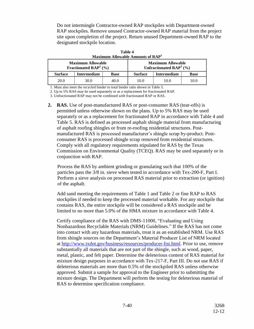
Do not intermingle Contractor-owned RAP stockpiles with Department-owned
RAP stockpiles. Remove unused Contractor-owned RAP material from the project
site upon completion of the project. Return unused Department-owned RAP to the
designated stockpile location.
Table 4
Maximum Allowable Amounts of RAP1
Maximum Allowable
Fractionated RAP2 (%)
Maximum Allowable
Unfractionated RAP3 (%)
Surface Intermediate Base Surface Intermediate Base
20.0 30.0 40.0 10.0 10.0 10.0
1. Must also meet the recycled binder to total binder ratio shown in Table 5.
2. Up to 5% RAS may be used separately or as a replacement for fractionated RAP.
3. Unfractionated RAP may not be combined with fractionated RAP or RAS.
2. RAS. Use of post-manufactured RAS or post-consumer RAS (tear-offs) is
permitted unless otherwise shown on the plans. Up to 5% RAS may be used
separately or as a replacement for fractionated RAP in accordance with Table 4 and
Table 5. RAS is defined as processed asphalt shingle material from manufacturing
of asphalt roofing shingles or from re-roofing residential structures. Post-
manufactured RAS is processed manufacturer’s shingle scrap by-product. Post-
consumer RAS is processed shingle scrap removed from residential structures.
Comply with all regulatory requirements stipulated for RAS by the Texas
Commission on Environmental Quality (TCEQ). RAS may be used separately or in
conjunction with RAP.
Process the RAS by ambient grinding or granulating such that 100% of the
particles pass the 3/8 in. sieve when tested in accordance with Tex-200-F, Part I.
Perform a sieve analysis on processed RAS material prior to extraction (or ignition)
of the asphalt.
Add sand meeting the requirements of Table 1 and Table 2 or fine RAP to RAS
stockpiles if needed to keep the processed material workable. For any stockpile that
contains RAS, the entire stockpile will be considered a RAS stockpile and be
limited to no more than 5.0% of the HMA mixture in accordance with Table 4.
Certify compliance of the RAS with DMS-11000, “Evaluating and Using
Nonhazardous Recyclable Materials (NRM) Guidelines.” If the RAS has not come
into contact with any hazardous materials, treat it as an established NRM. Use RAS
from shingle sources on the Department’s Material Producer List of NRM located
at http://www.txdot.gov/business/resources/producer-list.html. Prior to use, remove
substantially all materials that are not part of the shingle, such as wood, paper,
metal, plastic, and felt paper. Determine the deleterious content of RAS material for
mixture design purposes in accordance with Tex-217-F, Part III. Do not use RAS if
deleterious materials are more than 0.5% of the stockpiled RAS unless otherwise
approved. Submit a sample for approval to the Engineer prior to submitting the
mixture design. The Department will perform the testing for deleterious material of
RAS to determine specification compliance.
8-40 3268
12-12
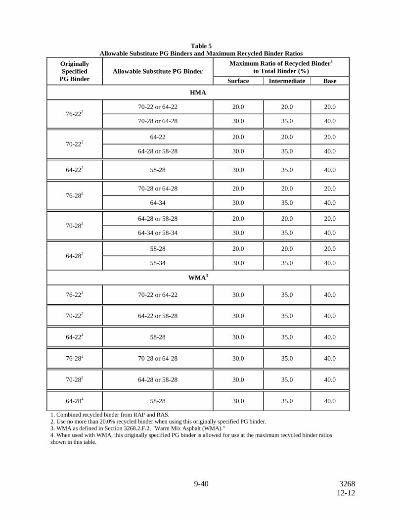
H. Substitute Binders. Unless otherwise shown on the plans, the Contractor may use a
substitute PG binder listed in Table 5 in lieu of the PG binder originally specified, if the
substitute PG binder and mixture made with the substitute PG binder meet the
following:
the substitute binder meets the specification requirements for the substitute binder
grade in accordance with Section 300.2.J, “Performance-Graded Binders”;
the substitute binder has an un-aged dynamic shear value less than or equal to
2.00 kPa and an RTFO aged dynamic shear value less than or equal to 5.00 kPa at
the PG test temperature; and
the mixture has less than 10.0 mm of rutting on the Hamburg Wheel test
(Tex-242-F) after the number of passes required for the originally specified binder.
Use of substitute PG binders may only be allowed at the discretion of the Engineer
if the Hamburg Wheel test results are between 10.0 mm and 12.5 mm.
9-40 3268
12-12
Table 5
Allowable Substitute PG Binders and Maximum Recycled Binder Ratios
Originally
Specified
PG Binder
Allowable Substitute PG Binder
Maximum Ratio of Recycled Binder1
to Total Binder (%)
Surface Intermediate Base
HMA
76-222
70-22 or 64-22 20.0 20.0 20.0
70-28 or 64-28 30.0 35.0 40.0
70-222
64-22 20.0 20.0 20.0
64-28 or 58-28 30.0 35.0 40.0
64-222 58-28 30.0 35.0 40.0
76-282
70-28 or 64-28 20.0 20.0 20.0
64-34 30.0 35.0 40.0
70-282
64-28 or 58-28 20.0 20.0 20.0
64-34 or 58-34 30.0 35.0 40.0
64-282
58-28 20.0 20.0 20.0
58-34 30.0 35.0 40.0
WMA3
76-222 70-22 or 64-22 30.0 35.0 40.0
70-222 64-22 or 58-28 30.0 35.0 40.0
64-224 58-28 30.0 35.0 40.0
76-282 70-28 or 64-28 30.0 35.0 40.0
70-282 64-28 or 58-28 30.0 35.0 40.0
64-284 58-28 30.0 35.0 40.0
1. Combined recycled binder from RAP and RAS.
2. Use no more than 20.0% recycled binder when using this originally specified PG binder.
3. WMA as defined in Section 3268.2.F.2, "Warm Mix Asphalt (WMA)."
4. When used with WMA, this originally specified PG binder is allowed for use at the maximum recycled binder ratios
shown in this table.
10-40 3268
12-12
3. Equipment. Provide required or necessary equipment in accordance with Item 320,
“Equipment for Asphalt Concrete Pavement.”
4. Construction. Produce, haul, place, and compact the specified paving mixture. In addition
to tests required by the specification, Contractors may perform other QC tests as deemed
necessary. At any time during the project, the Engineer may perform production and
placement tests as deemed necessary in accordance with Item 5, “Control of the Work.” On
or before the first day of paving, it is mandatory to schedule and participate in a pre-paving
meeting with the Engineer unless otherwise shown on the plans.
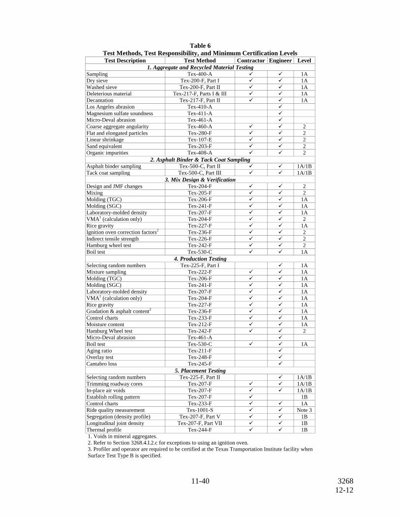
A. Certification. Personnel certified by the Hot Mix Asphalt Center Certification Program
must conduct all mixture designs, sampling, and testing in accordance with Table 6.
Supply the Engineer with a list of certified personnel and copies of their current
certificates before beginning production and when personnel changes are made. Provide
a mixture design that is developed and signed by a Level 2 certified specialist. Provide a
Level 1A certified specialist at the plant during production operations. Provide a
Level 1B certified specialist to conduct placement tests.
11-40 3268
12-12
Table 6
Test Methods, Test Responsibility, and Minimum Certification Levels
Test Description Test Method Contractor Engineer Level
1. Aggregate and Recycled Material Testing Sampling Tex-400-A 1A
Dry sieve Tex-200-F, Part I 1A
Washed sieve Tex-200-F, Part II 1A
Deleterious material Tex-217-F, Parts I & III 1A
Decantation Tex-217-F, Part II 1A
Los Angeles abrasion Tex-410-A
Magnesium sulfate soundness Tex-411-A
Micro-Deval abrasion Tex-461-A
Coarse aggregate angularity Tex-460-A 2
Flat and elongated particles Tex-280-F 2
Linear shrinkage Tex-107-E 2
Sand equivalent Tex-203-F 2
Organic impurities Tex-408-A 2
2. Asphalt Binder & Tack Coat Sampling Asphalt binder sampling Tex-500-C, Part II 1A/1B
Tack coat sampling Tex-500-C, Part III 1A/1B
3. Mix Design & Verification Design and JMF changes Tex-204-F 2
Mixing Tex-205-F 2
Molding (TGC) Tex-206-F 1A
Molding (SGC) Tex-241-F 1A
Laboratory-molded density Tex-207-F 1A
VMA1 (calculation only) Tex-204-F 2
Rice gravity Tex-227-F 1A
Ignition oven correction factors2 Tex-236-F 2
Indirect tensile strength Tex-226-F 2
Hamburg wheel test Tex-242-F 2
Boil test Tex-530-C 1A
4. Production Testing Selecting random numbers Tex-225-F, Part I 1A
Mixture sampling Tex-222-F 1A
Molding (TGC) Tex-206-F 1A
Molding (SGC) Tex-241-F 1A
Laboratory-molded density Tex-207-F 1A
VMA1 (calculation only) Tex-204-F 1A
Rice gravity Tex-227-F 1A
Gradation & asphalt content2 Tex-236-F 1A
Control charts Tex-233-F 1A
Moisture content Tex-212-F 1A
Hamburg Wheel test Tex-242-F 2
Micro-Deval abrasion Tex-461-A
Boil test Tex-530-C 1A
Aging ratio Tex-211-F
Overlay test Tex-248-F
Cantabro loss Tex-245-F
5. Placement Testing Selecting random numbers Tex-225-F, Part II 1A/1B
Trimming roadway cores Tex-207-F 1A/1B
In-place air voids Tex-207-F 1A/1B
Establish rolling pattern Tex-207-F 1B
Control charts Tex-233-F 1A
Ride quality measurement Tex-1001-S Note 3
Segregation (density profile) Tex-207-F, Part V 1B
Longitudinal joint density Tex-207-F, Part VII 1B
Thermal profile Tex-244-F 1B
1. Voids in mineral aggregates.
2. Refer to Section 3268.4.I.2.c for exceptions to using an ignition oven.
3. Profiler and operator are required to be certified at the Texas Transportation Institute facility when
Surface Test Type B is specified.
12-40 3268
12-12
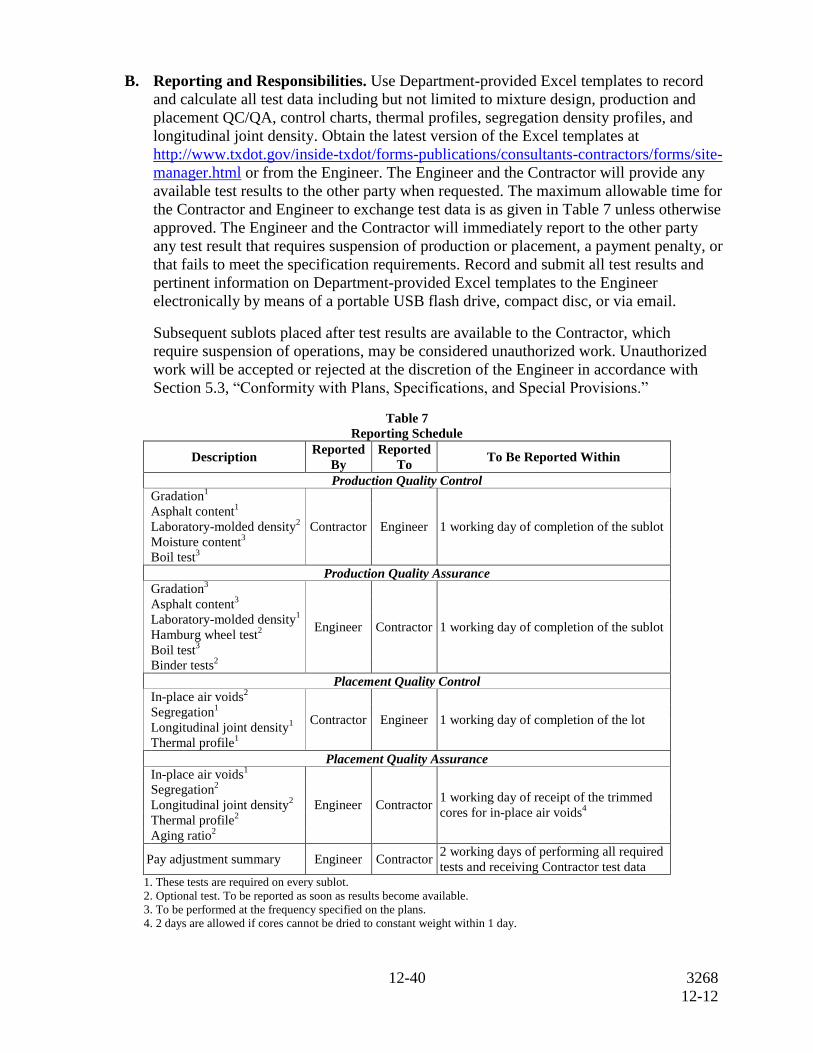
B. Reporting and Responsibilities. Use Department-provided Excel templates to record
and calculate all test data including but not limited to mixture design, production and
placement QC/QA, control charts, thermal profiles, segregation density profiles, and
longitudinal joint density. Obtain the latest version of the Excel templates at
http://www.txdot.gov/inside-txdot/forms-publications/consultants-contractors/forms/site-
manager.html or from the Engineer. The Engineer and the Contractor will provide any
available test results to the other party when requested. The maximum allowable time for
the Contractor and Engineer to exchange test data is as given in Table 7 unless otherwise
approved. The Engineer and the Contractor will immediately report to the other party
any test result that requires suspension of production or placement, a payment penalty, or
that fails to meet the specification requirements. Record and submit all test results and
pertinent information on Department-provided Excel templates to the Engineer
electronically by means of a portable USB flash drive, compact disc, or via email.
Subsequent sublots placed after test results are available to the Contractor, which
require suspension of operations, may be considered unauthorized work. Unauthorized
work will be accepted or rejected at the discretion of the Engineer in accordance with
Section 5.3, “Conformity with Plans, Specifications, and Special Provisions.”
Table 7
Reporting Schedule
Description Reported
By
Reported
To To Be Reported Within
Production Quality Control Gradation
1
Contractor Engineer 1 working day of completion of the sublot
Asphalt content1
Laboratory-molded density2
Moisture content3
Boil test3
Production Quality Assurance
Gradation3
Engineer Contractor 1 working day of completion of the sublot
Asphalt content3
Laboratory-molded density1
Hamburg wheel test2
Boil test3
Binder tests2
Placement Quality Control
In-place air voids2
Contractor Engineer 1 working day of completion of the lot Segregation
1
Longitudinal joint density1
Thermal profile1
Placement Quality Assurance
In-place air voids1
Engineer Contractor 1 working day of receipt of the trimmed
cores for in-place air voids4
Segregation2
Longitudinal joint density2
Thermal profile2
Aging ratio2
Pay adjustment summary Engineer Contractor 2 working days of performing all required
tests and receiving Contractor test data 1. These tests are required on every sublot.
2. Optional test. To be reported as soon as results become available.
3. To be performed at the frequency specified on the plans.
4. 2 days are allowed if cores cannot be dried to constant weight within 1 day.
13-40 3268
12-12
The Engineer will use the Department-provided Excel template to calculate all pay
adjustment factors for the lot. Sublot samples may be discarded after the Engineer and
Contractor sign off on the pay adjustment summary documentation for the lot.
Use the procedures described in Tex-233-F to plot the results of all quality control (QC)
and quality assurance (QA) testing. Update the control charts as soon as test results for
each sublot become available. Make the control charts readily accessible at the field
laboratory. The Engineer may suspend production for failure to update control charts.
C. Quality Control Plan (QCP). Develop and follow the QCP in detail. Obtain approval
from the Engineer for changes to the QCP made during the project. The Engineer may
suspend operations if the Contractor fails to comply with the QCP.
Submit a written QCP to the Engineer before the mandatory pre-paving meeting.
Receive the Engineer’s approval of the QCP before beginning production. Include the
following items in the QCP:
1. Project Personnel. For project personnel, include:
a list of individuals responsible for QC with authority to take corrective action;
contact information for each individual listed; and
copies of certification documents for individuals performing specified QC
functions.
2. Material Delivery and Storage. For material delivery and storage, include:
the sequence of material processing, delivery, and minimum quantities to
assure continuous plant operations;
aggregate stockpiling procedures to avoid contamination and segregation;
frequency, type, and timing of aggregate stockpile testing to assure
conformance of material requirements before mixture production; and
procedure for monitoring the quality and variability of asphalt binder.
3. Production. For production, include:
loader operation procedures to avoid contamination in cold bins;
procedures for calibrating and controlling cold feeds;
procedures to eliminate debris or oversized material;
procedures for adding and verifying rates of each applicable mixture
component (e.g., aggregate, asphalt binder, RAP, RAS, lime, liquid antistrip);
procedures for reporting job control test results; and
procedures to avoid segregation and drain-down in the silo.
4. Loading and Transporting. For loading and transporting, include:
type and application method for release agents; and
truck loading procedures to avoid segregation.
14-40 3268
12-12
5. Placement and Compaction. For placement and compaction, include:
proposed agenda for mandatory pre-paving meeting, including date and
location;
proposed paving plan (e.g., paving widths and lift thicknesses);
type and application method for release agents in the paver and on rollers,
shovels, lutes, and other utensils;
procedures for the transfer of mixture into the paver, while avoiding
segregation and preventing material spillage;
process to balance production, delivery, paving, and compaction to achieve
continuous placement operations and good ride quality;
paver operations (e.g., operation of wings, height of mixture in auger chamber)
to avoid physical and thermal segregation and other surface irregularities; and
procedures to construct quality longitudinal and transverse joints.
D. Mixture Design.
1. Design Requirements. The Contractor may elect to design the mixture using a
Texas Gyratory Compactor (TGC) or a Superpave Gyratory Compactor (SGC)
unless otherwise shown on the plans. Use the typical weight design example given
in Tex-204-F, Part I, when using a TGC. Use the Superpave mixture design
procedure given in Tex-204-F, Part IV, when using a SGC. Design the mixture to
meet the requirements listed in Tables 1, 2, 3, 4, 5, 8, 9, and 10.
a. Target Laboratory Molded Density When The TGC Is Used. Design the
mixture at a 96.5% target laboratory-molded density or as noted in Table 9.
The target laboratory-molded density may be increased in 0.5% increments,
not to exceed 97.0%, at the Contractor’s discretion.
b. Design Number of Gyrations (Ndesign) When The SGC Is Used. Design
the mixture at 50 gyrations (Ndesign). Use a target laboratory-molded density
of 96.0% to design the mixture; however, adjustments can be made to the
Ndesign value as noted in Table 9. The Ndesign level may be reduced to no
less than 35 gyrations at the Contractor’s discretion.
Use an approved laboratory to perform the Hamburg Wheel test and provide results
with the mixture design, or provide the laboratory mixture and request that the
Department perform the Hamburg Wheel test. The Department maintains the
Material Producer List of approved laboratories located at
http://www.txdot.gov/business/resources/producer-list.html. The Engineer will be
allowed 10 working days to provide the Contractor with Hamburg Wheel test
results on the laboratory mixture design.
The Engineer will provide the mixture design when shown on the plans. The
Contractor may submit a new mixture design at any time during the project. The
Engineer will verify and approve all mixture designs (JMF1) before the Contractor
can begin production.
15-40 3268
12-12
Provide the Engineer with a mixture design report using the Department-provided
Excel template. Include the following items in the report:
the combined aggregate gradation, source, specific gravity, and percent of each
material used;
asphalt content and aggregate gradation of RAP and RAS stockpiles;
the target laboratory-molded density (or Ndesign level when using the SGC);
results of all applicable tests;
the mixing and molding temperatures;
the signature of the Level 2 person or persons that performed the design;
the date the mixture design was performed; and
a unique identification number for the mixture design.
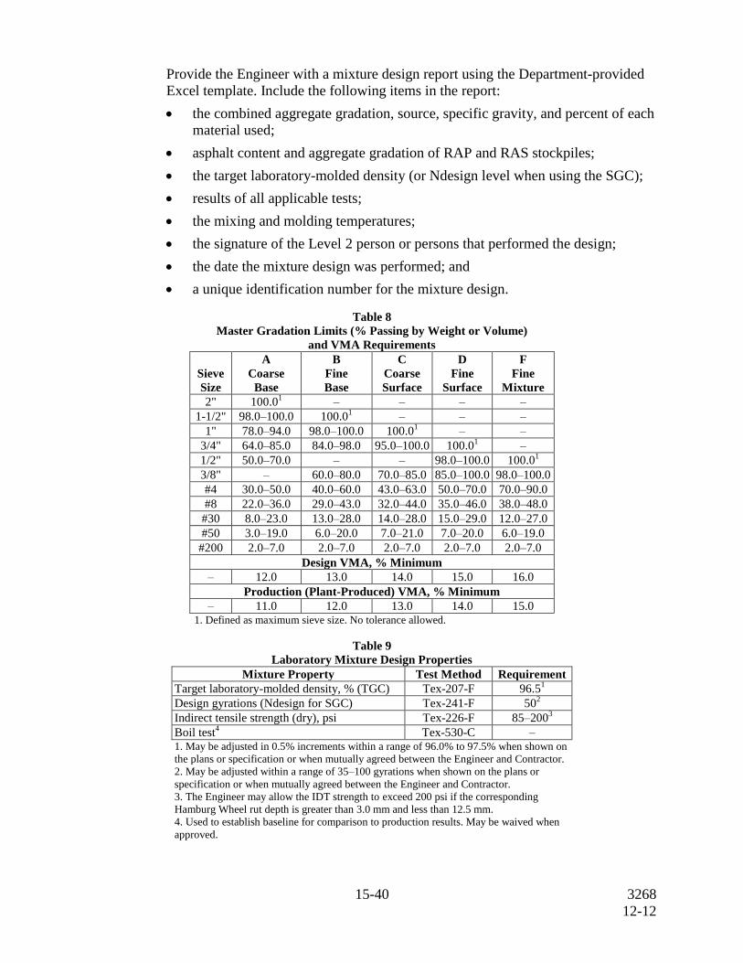
Table 8
Master Gradation Limits (% Passing by Weight or Volume)
and VMA Requirements
Sieve
Size
A
Coarse
Base
B
Fine
Base
C
Coarse
Surface
D
Fine
Surface
F
Fine
Mixture
2" 100.01 – – – –
1-1/2" 98.0–100.0 100.01 – – –
1" 78.0–94.0 98.0–100.0 100.01 – –
3/4" 64.0–85.0 84.0–98.0 95.0–100.0 100.01 –
1/2" 50.0–70.0 – – 98.0–100.0 100.01
3/8" – 60.0–80.0 70.0–85.0 85.0–100.0 98.0–100.0
#4 30.0–50.0 40.0–60.0 43.0–63.0 50.0–70.0 70.0–90.0
#8 22.0–36.0 29.0–43.0 32.0–44.0 35.0–46.0 38.0–48.0
#30 8.0–23.0 13.0–28.0 14.0–28.0 15.0–29.0 12.0–27.0
#50 3.0–19.0 6.0–20.0 7.0–21.0 7.0–20.0 6.0–19.0
#200 2.0–7.0 2.0–7.0 2.0–7.0 2.0–7.0 2.0–7.0
Design VMA, % Minimum
– 12.0 13.0 14.0 15.0 16.0
Production (Plant-Produced) VMA, % Minimum
– 11.0 12.0 13.0 14.0 15.0 1. Defined as maximum sieve size. No tolerance allowed.
Table 9
Laboratory Mixture Design Properties
Mixture Property Test Method Requirement
Target laboratory-molded density, % (TGC) Tex-207-F 96.51
Design gyrations (Ndesign for SGC) Tex-241-F 502
Indirect tensile strength (dry), psi Tex-226-F
85–2003
Boil test4
Tex-530-C – 1. May be adjusted in 0.5% increments within a range of 96.0% to 97.5% when shown on
the plans or specification or when mutually agreed between the Engineer and Contractor.
2. May be adjusted within a range of 35–100 gyrations when shown on the plans or
specification or when mutually agreed between the Engineer and Contractor.
3. The Engineer may allow the IDT strength to exceed 200 psi if the corresponding
Hamburg Wheel rut depth is greater than 3.0 mm and less than 12.5 mm.
4. Used to establish baseline for comparison to production results. May be waived when
approved.
16-40 3268
12-12
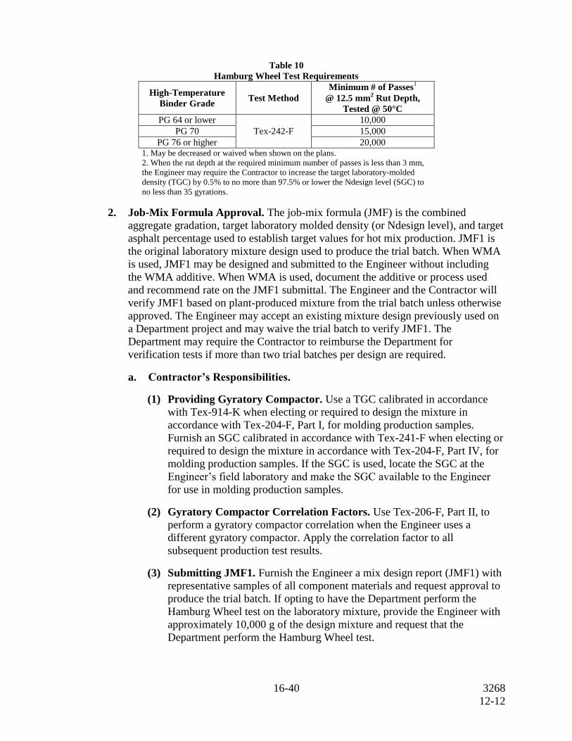
Table 10
Hamburg Wheel Test Requirements
High-Temperature
Binder Grade Test Method
Minimum # of Passes1
@ 12.5 mm2 Rut Depth,
Tested @ 50°C
PG 64 or lower
Tex-242-F
10,000
PG 70 15,000
PG 76 or higher 20,000 1. May be decreased or waived when shown on the plans.
2. When the rut depth at the required minimum number of passes is less than 3 mm,
the Engineer may require the Contractor to increase the target laboratory-molded
density (TGC) by 0.5% to no more than 97.5% or lower the Ndesign level (SGC) to
no less than 35 gyrations.
2. Job-Mix Formula Approval. The job-mix formula (JMF) is the combined
aggregate gradation, target laboratory molded density (or Ndesign level), and target
asphalt percentage used to establish target values for hot mix production. JMF1 is
the original laboratory mixture design used to produce the trial batch. When WMA
is used, JMF1 may be designed and submitted to the Engineer without including
the WMA additive. When WMA is used, document the additive or process used
and recommend rate on the JMF1 submittal. The Engineer and the Contractor will
verify JMF1 based on plant-produced mixture from the trial batch unless otherwise
approved. The Engineer may accept an existing mixture design previously used on
a Department project and may waive the trial batch to verify JMF1. The
Department may require the Contractor to reimburse the Department for
verification tests if more than two trial batches per design are required.
a. Contractor’s Responsibilities.
(1) Providing Gyratory Compactor. Use a TGC calibrated in accordance
with Tex-914-K when electing or required to design the mixture in
accordance with Tex-204-F, Part I, for molding production samples.
Furnish an SGC calibrated in accordance with Tex-241-F when electing or
required to design the mixture in accordance with Tex-204-F, Part IV, for
molding production samples. If the SGC is used, locate the SGC at the
Engineer’s field laboratory and make the SGC available to the Engineer
for use in molding production samples.
(2) Gyratory Compactor Correlation Factors. Use Tex-206-F, Part II, to
perform a gyratory compactor correlation when the Engineer uses a
different gyratory compactor. Apply the correlation factor to all
subsequent production test results.
(3) Submitting JMF1. Furnish the Engineer a mix design report (JMF1) with
representative samples of all component materials and request approval to
produce the trial batch. If opting to have the Department perform the
Hamburg Wheel test on the laboratory mixture, provide the Engineer with
approximately 10,000 g of the design mixture and request that the
Department perform the Hamburg Wheel test.
17-40 3268
12-12
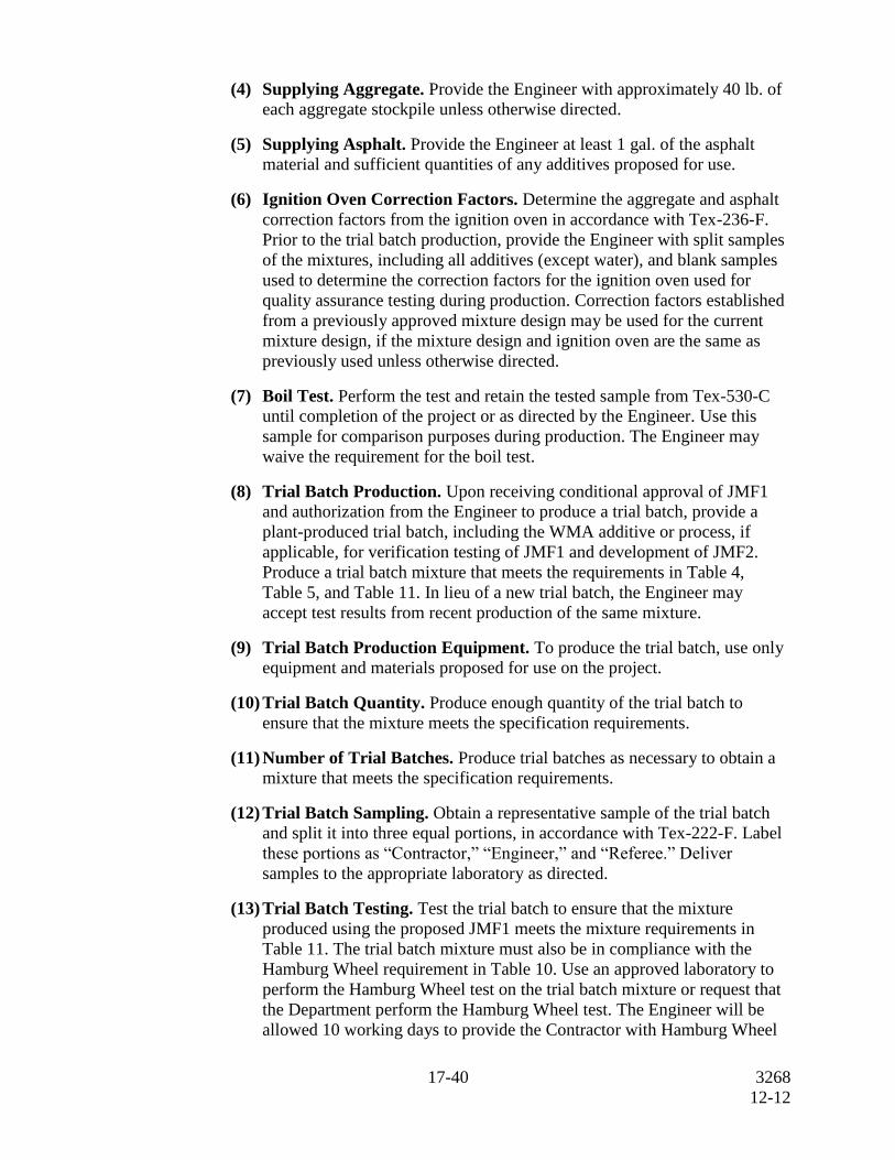
(4) Supplying Aggregate. Provide the Engineer with approximately 40 lb. of
each aggregate stockpile unless otherwise directed.
(5) Supplying Asphalt. Provide the Engineer at least 1 gal. of the asphalt
material and sufficient quantities of any additives proposed for use.
(6) Ignition Oven Correction Factors. Determine the aggregate and asphalt
correction factors from the ignition oven in accordance with Tex-236-F.
Prior to the trial batch production, provide the Engineer with split samples
of the mixtures, including all additives (except water), and blank samples
used to determine the correction factors for the ignition oven used for
quality assurance testing during production. Correction factors established
from a previously approved mixture design may be used for the current
mixture design, if the mixture design and ignition oven are the same as
previously used unless otherwise directed.
(7) Boil Test. Perform the test and retain the tested sample from Tex-530-C
until completion of the project or as directed by the Engineer. Use this
sample for comparison purposes during production. The Engineer may
waive the requirement for the boil test.
(8) Trial Batch Production. Upon receiving conditional approval of JMF1
and authorization from the Engineer to produce a trial batch, provide a
plant-produced trial batch, including the WMA additive or process, if
applicable, for verification testing of JMF1 and development of JMF2.
Produce a trial batch mixture that meets the requirements in Table 4,
Table 5, and Table 11. In lieu of a new trial batch, the Engineer may
accept test results from recent production of the same mixture.
(9) Trial Batch Production Equipment. To produce the trial batch, use only
equipment and materials proposed for use on the project.
(10) Trial Batch Quantity. Produce enough quantity of the trial batch to
ensure that the mixture meets the specification requirements.
(11) Number of Trial Batches. Produce trial batches as necessary to obtain a
mixture that meets the specification requirements.
(12) Trial Batch Sampling. Obtain a representative sample of the trial batch
and split it into three equal portions, in accordance with Tex-222-F. Label
these portions as “Contractor,” “Engineer,” and “Referee.” Deliver
samples to the appropriate laboratory as directed.
(13) Trial Batch Testing. Test the trial batch to ensure that the mixture
produced using the proposed JMF1 meets the mixture requirements in
Table 11. The trial batch mixture must also be in compliance with the
Hamburg Wheel requirement in Table 10. Use an approved laboratory to
perform the Hamburg Wheel test on the trial batch mixture or request that
the Department perform the Hamburg Wheel test. The Engineer will be
allowed 10 working days to provide the Contractor with Hamburg Wheel
18-40 3268
12-12
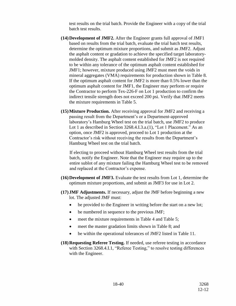
test results on the trial batch. Provide the Engineer with a copy of the trial
batch test results.
(14) Development of JMF2. After the Engineer grants full approval of JMF1
based on results from the trial batch, evaluate the trial batch test results,
determine the optimum mixture proportions, and submit as JMF2. Adjust
the asphalt content or gradation to achieve the specified target laboratory-
molded density. The asphalt content established for JMF2 is not required
to be within any tolerance of the optimum asphalt content established for
JMF1; however, mixture produced using JMF2 must meet the voids in
mineral aggregates (VMA) requirements for production shown in Table 8.
If the optimum asphalt content for JMF2 is more than 0.5% lower than the
optimum asphalt content for JMF1, the Engineer may perform or require
the Contractor to perform Tex-226-F on Lot 1 production to confirm the
indirect tensile strength does not exceed 200 psi. Verify that JMF2 meets
the mixture requirements in Table 5.
(15) Mixture Production. After receiving approval for JMF2 and receiving a
passing result from the Department’s or a Department-approved
laboratory’s Hamburg Wheel test on the trial batch, use JMF2 to produce
Lot 1 as described in Section 3268.4.I.3.a.(1), “Lot 1 Placement.” As an
option, once JMF2 is approved, proceed to Lot 1 production at the
Contractor’s risk without receiving the results from the Department’s
Hamburg Wheel test on the trial batch.
If electing to proceed without Hamburg Wheel test results from the trial
batch, notify the Engineer. Note that the Engineer may require up to the
entire sublot of any mixture failing the Hamburg Wheel test to be removed
and replaced at the Contractor’s expense.
(16) Development of JMF3. Evaluate the test results from Lot 1, determine the
optimum mixture proportions, and submit as JMF3 for use in Lot 2.
(17) JMF Adjustments. If necessary, adjust the JMF before beginning a new
lot. The adjusted JMF must:
be provided to the Engineer in writing before the start on a new lot;
be numbered in sequence to the previous JMF;
meet the mixture requirements in Table 4 and Table 5;
meet the master gradation limits shown in Table 8; and
be within the operational tolerances of JMF2 listed in Table 11.
(18) Requesting Referee Testing. If needed, use referee testing in accordance
with Section 3268.4.I.1, “Referee Testing,” to resolve testing differences
with the Engineer.
19-40 3268
12-12
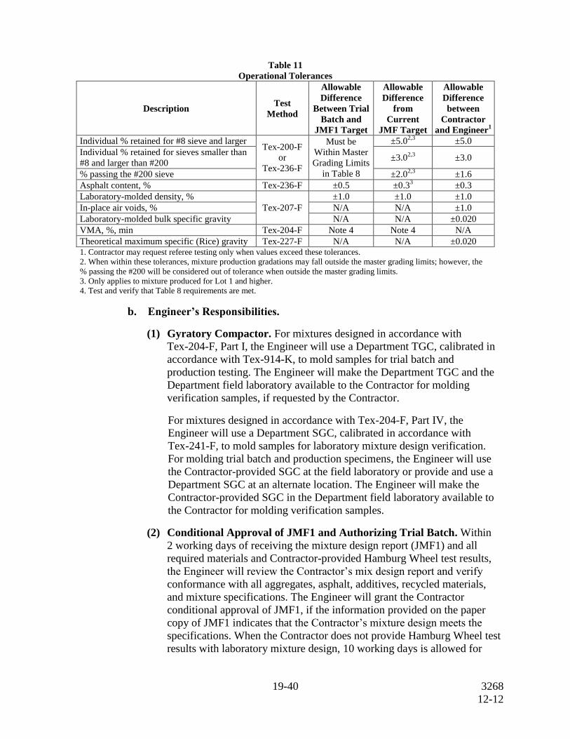
Table 11
Operational Tolerances
Description Test
Method
Allowable
Difference
Between Trial
Batch and
JMF1 Target
Allowable
Difference
from
Current
JMF Target
Allowable
Difference
between
Contractor
and Engineer1
Individual % retained for #8 sieve and larger Tex-200-F
or
Tex-236-F
Must be
Within Master
Grading Limits
in Table 8
±5.02,3
±5.0
Individual % retained for sieves smaller than
#8 and larger than #200 ±3.0
2,3 ±3.0
% passing the #200 sieve ±2.02,3
±1.6
Asphalt content, % Tex-236-F ±0.5
±0.33 ±0.3
Laboratory-molded density, %
Tex-207-F
±1.0 ±1.0 ±1.0
In-place air voids, % N/A N/A ±1.0
Laboratory-molded bulk specific gravity N/A N/A ±0.020
VMA, %, min Tex-204-F Note 4 Note 4 N/A
Theoretical maximum specific (Rice) gravity Tex-227-F N/A N/A ±0.020 1. Contractor may request referee testing only when values exceed these tolerances.
2. When within these tolerances, mixture production gradations may fall outside the master grading limits; however, the
% passing the #200 will be considered out of tolerance when outside the master grading limits.
3. Only applies to mixture produced for Lot 1 and higher.
4. Test and verify that Table 8 requirements are met.
b. Engineer’s Responsibilities.
(1) Gyratory Compactor. For mixtures designed in accordance with
Tex-204-F, Part I, the Engineer will use a Department TGC, calibrated in
accordance with Tex-914-K, to mold samples for trial batch and
production testing. The Engineer will make the Department TGC and the
Department field laboratory available to the Contractor for molding
verification samples, if requested by the Contractor.
For mixtures designed in accordance with Tex-204-F, Part IV, the
Engineer will use a Department SGC, calibrated in accordance with
Tex-241-F, to mold samples for laboratory mixture design verification.
For molding trial batch and production specimens, the Engineer will use
the Contractor-provided SGC at the field laboratory or provide and use a
Department SGC at an alternate location. The Engineer will make the
Contractor-provided SGC in the Department field laboratory available to
the Contractor for molding verification samples.
(2) Conditional Approval of JMF1 and Authorizing Trial Batch. Within
2 working days of receiving the mixture design report (JMF1) and all
required materials and Contractor-provided Hamburg Wheel test results,
the Engineer will review the Contractor’s mix design report and verify
conformance with all aggregates, asphalt, additives, recycled materials,
and mixture specifications. The Engineer will grant the Contractor
conditional approval of JMF1, if the information provided on the paper
copy of JMF1 indicates that the Contractor’s mixture design meets the
specifications. When the Contractor does not provide Hamburg Wheel test
results with laboratory mixture design, 10 working days is allowed for
20-40 3268
12-12
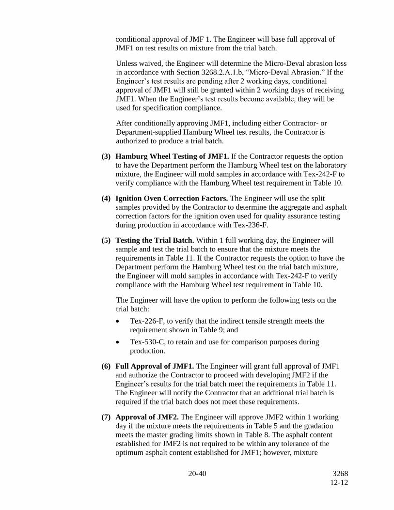
conditional approval of JMF 1. The Engineer will base full approval of
JMF1 on test results on mixture from the trial batch.
Unless waived, the Engineer will determine the Micro-Deval abrasion loss
in accordance with Section 3268.2.A.1.b, “Micro-Deval Abrasion.” If the
Engineer’s test results are pending after 2 working days, conditional
approval of JMF1 will still be granted within 2 working days of receiving
JMF1. When the Engineer’s test results become available, they will be
used for specification compliance.
After conditionally approving JMF1, including either Contractor- or
Department-supplied Hamburg Wheel test results, the Contractor is
authorized to produce a trial batch.
(3) Hamburg Wheel Testing of JMF1. If the Contractor requests the option
to have the Department perform the Hamburg Wheel test on the laboratory
mixture, the Engineer will mold samples in accordance with Tex-242-F to
verify compliance with the Hamburg Wheel test requirement in Table 10.
(4) Ignition Oven Correction Factors. The Engineer will use the split
samples provided by the Contractor to determine the aggregate and asphalt
correction factors for the ignition oven used for quality assurance testing
during production in accordance with Tex-236-F.
(5) Testing the Trial Batch. Within 1 full working day, the Engineer will
sample and test the trial batch to ensure that the mixture meets the
requirements in Table 11. If the Contractor requests the option to have the
Department perform the Hamburg Wheel test on the trial batch mixture,
the Engineer will mold samples in accordance with Tex-242-F to verify
compliance with the Hamburg Wheel test requirement in Table 10.
The Engineer will have the option to perform the following tests on the
trial batch:
Tex-226-F, to verify that the indirect tensile strength meets the
requirement shown in Table 9; and
Tex-530-C, to retain and use for comparison purposes during
production.
(6) Full Approval of JMF1. The Engineer will grant full approval of JMF1
and authorize the Contractor to proceed with developing JMF2 if the
Engineer’s results for the trial batch meet the requirements in Table 11.
The Engineer will notify the Contractor that an additional trial batch is
required if the trial batch does not meet these requirements.
(7) Approval of JMF2. The Engineer will approve JMF2 within 1 working
day if the mixture meets the requirements in Table 5 and the gradation
meets the master grading limits shown in Table 8. The asphalt content
established for JMF2 is not required to be within any tolerance of the
optimum asphalt content established for JMF1; however, mixture
21-40 3268
12-12
produced using JMF2 must meet the VMA requirements shown in Table 8.
If the optimum asphalt content for JMF2 is more than 0.5% lower than the
optimum asphalt content for JMF1, the Engineer may perform or require
the Contractor to perform Tex-226-F on Lot 1 production to confirm the
indirect tensile strength does not exceed 200 psi.
(8) Approval of Lot 1 Production. The Engineer will authorize the
Contractor to proceed with Lot 1 production (using JMF2) as soon as a
passing result is achieved from the Department’s or a Department-
approved laboratory’s Hamburg Wheel test on the trial batch. The
Contractor may proceed at its own risk with Lot 1 production without the
results from the Hamburg Wheel test on the trial batch.
If the Department’s or Department-approved laboratory’s sample from the
trial batch fails the Hamburg Wheel test, the Engineer will suspend
production until further Hamburg Wheel tests meet the specified values.
The Engineer may require up to the entire sublot of any mixture failing the
Hamburg Wheel test be removed and replaced at the Contractor’s expense.
(9) Approval of JMF3 and Subsequent JMF Changes. JMF3 and
subsequent JMF changes are approved if they meet the mixture
requirements shown in Table 4, Table 5, the master grading limits shown
in Table 8, and are within the operational tolerances of JMF2 shown in
Table 11.
E. Production Operations. Perform a new trial batch when the plant or plant location is
changed. Take corrective action and receive approval to proceed after any production
suspension for noncompliance to the specification. Submit a new mix design and
perform a new trial batch when the asphalt content of:
either RAP stockpile used in the mix is more than 0.5% higher than the value
shown on the mixture design report; or
RAS stockpile used in the mix is more than 2.0% higher than the value shown on
the mixture design report.
1. Storage and Heating of Materials. Do not heat the asphalt binder above the
temperatures specified in Item 300, “Asphalts, Oils, and Emulsions,” or outside the
manufacturer’s recommended values. On a daily basis, provide the Engineer with
the records of asphalt binder and hot-mix asphalt discharge temperatures (in legible
and discernible increments) in accordance with Item 320, “Equipment for Asphalt
Concrete Pavement.” Do not store mixture for a period long enough to affect the
quality of the mixture, nor in any case longer than 12 hr unless otherwise approved.
2. Mixing and Discharge of Materials. Notify the Engineer of the target discharge
temperature and produce the mixture within 25°F of the target. Monitor the
temperature of the material in the truck before shipping to ensure that it does not
exceed 350°F (or 275ºF for WMA) and is not lower than 215°F. The Department
will not pay for or allow placement of any mixture produced at more than 350°F.
22-40 3268
12-12
When WMA is required, produce the WMA within the target temperature discharge
range of 215ºF and 275ºF. Take corrective action any time the discharge
temperature of the WMA exceeds the target discharge range. The Engineer may
suspend production operations if the Contractor’s corrective action is not successful
at controlling the production temperature within the target discharge range. Note
that when WMA is produced, it may be necessary to adjust burners to ensure
complete combustion such that no burner fuel residue remains in the mixture.
Control the mixing time and temperature so that substantially all moisture is
removed from the mixture before discharging from the plant. If requested,
determine the moisture content by oven-drying in accordance with Tex-212-F,
Part II, and verify that the mixture contains no more than 0.2% of moisture by
weight. Obtain the sample immediately after discharging the mixture into the truck,
and perform the test promptly.
F. Hauling Operations. Before use, clean all truck beds to ensure that mixture is not
contaminated. When a release agent is necessary, use a release agent on the
Department’s Material Producer List to coat the inside bed of the truck.
Use only equipment for hauling as defined in Section 3268.4.G.3.c, “Hauling
Equipment.” Other hauling equipment may be used when allowed by the Engineer.
G. Placement Operations. Collect haul tickets from each load of mixture delivered to the
project and provide the Department’s copy to the Engineer approximately every hour,
or as directed by the Engineer. When the Pave-IR system is not used for specification
compliance, use a non-contact infrared thermometer to measure and record the internal
temperature of the mixture as discharged from the truck or material transfer device prior
to or as the mix enters the paver and an approximate station number or GPS coordinates
on each ticket. Calculate the daily yield and cumulative yield for the specified lift and
provide to the Engineer at the end of paving operations for each day unless otherwise
directed. The Engineer may suspend production if the Contractor fails to produce and
provide haul tickets and yield calculations by the end of paving operations for each day.
Prepare the surface by removing raised pavement markers and objectionable material
such as moisture, dirt, sand, leaves, and other loose impediments from the surface
before placing mixture. Remove vegetation from pavement edges. Place the mixture to
meet the typical section requirements and produce a smooth, finished surface with a
uniform appearance and texture. Offset longitudinal joints of successive courses of hot
mix by at least 6 in. Place mixture so that longitudinal joints on the surface course
coincide with lane lines, or as directed. Ensure that all finished surfaces will drain
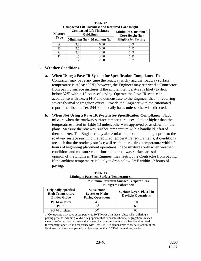
properly. Place the mixture at the rate or thickness shown on the plans. The Engineer
will use the guidelines in Table 12 to determine the compacted lift thickness of each
layer when multiple lifts are required. The thickness determined is based on the rate of
110 lb./sq. yd. for each inch of pavement unless otherwise shown on the plans.
23-40 3268
12-12
Table 12
Compacted Lift Thickness and Required Core Height
Mixture
Type
Compacted Lift Thickness
Guidelines Minimum Untrimmed
Core Height (in.)
Eligible for Testing Minimum (in.) Maximum (in.)
A 3.00 6.00 2.00
B 2.50 5.00 1.75
C 2.00 4.00 1.50
D 1.50 3.00 1.25
F 1.25 2.50 1.25
1. Weather Conditions.
a. When Using a Pave-IR System for Specification Compliance. The
Contractor may pave any time the roadway is dry and the roadway surface
temperature is at least 32°F; however, the Engineer may restrict the Contractor
from paving surface mixtures if the ambient temperature is likely to drop
below 32°F within 12 hours of paving. Operate the Pave-IR system in
accordance with Tex-244-F and demonstrate to the Engineer that no recurring
severe thermal segregation exists. Provide the Engineer with the automated
report described in Tex-244-F on a daily basis unless otherwise directed.
b. When Not Using a Pave-IR System for Specification Compliance. Place
mixture when the roadway surface temperature is equal to or higher than the
temperatures listed in Table 13 unless otherwise approved or as shown on the
plans. Measure the roadway surface temperature with a handheld infrared
thermometer. The Engineer may allow mixture placement to begin prior to the
roadway surface reaching the required temperature requirements, if conditions
are such that the roadway surface will reach the required temperature within 2
hours of beginning placement operations. Place mixtures only when weather
conditions and moisture conditions of the roadway surface are suitable in the
opinion of the Engineer. The Engineer may restrict the Contractor from paving
if the ambient temperature is likely to drop below 32°F within 12 hours of
paving.
Table 13
Minimum Pavement Surface Temperatures
Minimum Pavement Surface Temperatures
in Degrees Fahrenheit
Originally Specified
High Temperature
Binder Grade
Subsurface
Layers or Night
Paving Operations
Surface Layers Placed in
Daylight Operations
PG 64 or lower 45 50
PG 70 551 60
1
PG 76 or higher 601 60
1
1. Contractors may pave at temperatures 10°F lower than these values when utilizing a
paving process including WMA or equipment that eliminates thermal segregation. In such
cases, the Contractor must use either a hand held thermal camera or a hand held infrared
thermometer operated in accordance with Tex-244-F to demonstrate to the satisfaction of the
Engineer that the uncompacted mat has no more than 10°F of thermal segregation.
24-40 3268
12-12
2. Tack Coat. Clean the surface before placing the tack coat. Unless otherwise
approved, apply tack coat uniformly at the rate directed by the Engineer. The
Engineer will set the rate between 0.04 and 0.10 gal. of residual asphalt per square
yard of surface area. Apply the tack coat in a uniform manner to avoid streaks and
other irregular patterns. Apply a thin, uniform tack coat to all contact surfaces of
curbs, structures, and all joints. Allow adequate time for emulsion to break
completely prior to placing any material. Prevent splattering of tack coat when
placed adjacent to curb, gutter, and structures. Roll the tack coat with a pneumatic-
tire roller to remove streaks and other irregular patterns when directed.
3. Lay-Down Operations.
a. Thermal Profile. Use a thermal camera or an infrared thermometer to obtain
thermal profiles on each sublot in accordance with Tex-244-F. When the
Pave-IR system is not used for specification compliance, the Engineer will
obtain a thermal profile at least once per project. Thermal profiles are not
applicable in areas described in Section 3268.4.I.3.a(4), “Miscellaneous
Areas.”
Within 1 working day of the completion of each lot, provide the Engineer with
the thermal profile of every sublot within the lot. Report the results of each
thermal profile in accordance with Section 3268.4.B, “Reporting and
Responsibilities.”
(1) Moderate Thermal Segregation. Any areas that have a temperature
differential greater than 25°F but not exceeding 50°F are deemed as
having moderate thermal segregation. Take immediate corrective action to
eliminate the moderate thermal segregation. Evaluate areas with moderate
thermal segregation by performing density profiles in accordance with
Section 3268.4.I.3.c(2), “Segregation (Density Profile).”
(2) Severe Thermal Segregation. Any areas that have a temperature
differential greater than 50°F are deemed as having severe thermal
segregation. When the Pave-IR system is not used for specification
compliance, no production or placement bonus will be paid for any sublot
that contains severe thermal segregation. Suspend operations and take
immediate corrective action to eliminate severe thermal segregation unless
otherwise directed. Resume operations when the Engineer determines that
subsequent production will meet the requirements of this Section. Evaluate
areas with severe thermal segregation by performing density profiles in
accordance with Section 3268.4.I.3.c(2), “Segregation (Density Profile).”
Remove and replace the material in any areas that have both severe
thermal segregation and a failing result for Segregation (Density Profile)
unless otherwise directed. The sublot in question may receive a production
and placement bonus if applicable when the defective material is
successfully removed and replaced.
(3) Use of the Pave-IR System. In lieu of obtaining thermal profiles on each
sublot using a thermal camera or an infrared thermometer, the Contractor
25-40 3268
12-12
may use the Pave-IR system (paver mounted infrared bar) to obtain a
continuous thermal profile in accordance with Tex-244-F. When electing
to use the Pave-IR system, notify the Engineer prior to beginning
placement operations and specify if using the Pave-IR system for
specification compliance or for information only. When electing to use the
Pave-IR system for information only, use a thermal camera or an infrared
thermometer to obtain thermal profiles in accordance with Tex-244-F.
When electing to use the Pave-IR system for information only, segregation
density profiles are applicable.
When using the Pave-IR system for specification compliance, review the
output results on a daily basis. Unless otherwise directed, provide the
automated report described in Tex-244-F to the Engineer for review.
Modify the paving process as necessary to eliminate any recurring
(moderate or severe) thermal segregation identified by the Pave-IR
system. The Engineer may suspend paving operations if the Contractor
cannot successfully modify the paving process to eliminate recurring
severe thermal segregation. Density profiles are not required and are not
applicable when using the Pave-IR system for specification compliance.
Upon completion of use of the Pave-IR system for specification
compliance or as requested by the Engineer, provide the Engineer with
electronic copies of all daily data files that can be used with the Pave-IR
system software to generate temperature profile plots.
b. Windrow Operations. When hot mix is placed in windrows, operate windrow
pickup equipment so that substantially all the mixture deposited on the roadbed
is picked up and loaded into the paver.
c. Hauling Equipment. The Contractor may elect to use belly dumps, live
bottom, or end dump trucks to haul and transfer mixture; however, with
exception of paving miscellaneous areas, end dump trucks are only allowed
when used in conjunction with an MTD with remixing capability or when a
Pave-IR system is used for specification compliance unless otherwise allowed
by the Engineer.
d. Screed Heaters. If the paver stops for more than 5 minutes, turn off screed
heaters to prevent overheating of the mat. If the screed heater remains on for
more than 5 minutes while the paver is stopped, the Engineer may evaluate the
suspect area in accordance with Section 3268.4.I.3.c(4),“Recovered Asphalt
Dynamic Shear Rheometer (DSR).”
H. Compaction. Uniformly compact the pavement to contain between 3.8% and 8.5% in-
place air voids. When the in-place air voids exceed the range of 3.8% and 8.5%, take
immediate corrective action to bring the operation within these tolerances. Areas
defined in Section 3268.4.I.3.a(4), “Miscellaneous Areas,” are not subject to in-place air
void determination. In all other areas, the Engineer may obtain and test cores and may
suspend operations or require removal and replacement if the in-place air voids are less
than 2.7% or greater than 9.9%. The Engineer will allow paving to resume when the
proposed corrective action is likely to yield between 3.8% and 8.5% in-place air voids.
26-40 3268
12-12
Furnish the type, size, and number of rollers required for compaction as approved. Use
a pneumatic-tire roller to seal the surface unless excessive pickup of fines occurs. Use
additional rollers as required to remove any roller marks. Use only water or an approved
release agent on rollers, tamps, and other compaction equipment unless otherwise
directed.
On the first day of production, use the control strip method given in Tex-207-F, Part IV,
to establish the rolling pattern that will produce the desired in-place air voids unless
otherwise directed.
Use tamps to thoroughly compact the edges of the pavement along curbs, headers, and
similar structures and in locations that will not allow thorough compaction with rollers.
The Engineer may require rolling with a trench roller on widened areas, in trenches, and
in other limited areas.
Complete all compaction operations before the pavement temperature drops below
160°F unless otherwise allowed. The Engineer may allow compaction with a light finish
roller operated in static mode for pavement temperatures below 160°F.
Allow the compacted pavement to cool to 160°F or lower before opening to traffic
unless otherwise directed. When directed, sprinkle the finished mat with water or
limewater to expedite opening the roadway to traffic.
I. Acceptance Plan. Pay adjustments for the material will be in accordance with
Article 3268.6, “Payment.”
Sample and test the hot mix on a lot and sublot basis. If the production pay factor given
in Section 3268.6.A, “Production Pay Adjustment Factors,” for two consecutive lots or
the placement pay factor given in Section 3268.6.B, “Placement Pay Adjustment
Factors,” for two consecutive lots is below 1.000, suspend production until test results
or other information indicates to the satisfaction of the Engineer that the next material
produced or placed will result in pay factors of at least 1.000.
1. Referee Testing. The Construction Division is the referee laboratory. The
Contractor may request referee testing if a “remove and replace” condition is
determined based on the Engineer’s test results, or if the differences between
Contractor and Engineer test results exceed the maximum allowable difference
shown in Table 11 and the differences cannot be resolved. The Contractor may also
request referee testing if the Engineer’s test results require suspension of
production and the Contractor’s test results are within specification limits. Make
the request within 5 working days after receiving test results and cores from the
Engineer. Referee tests will be performed only on the sublot in question and only
for the particular tests in question. Allow 10 working days from the time the
samples are received at the referee laboratory for test results to be reported. The
Department may require the Contractor to reimburse the Department for referee
tests if more than three referee tests per project are required and the Engineer’s test
results are closer than the Contractor’s test results to the referee test results.
The Construction Division will determine the laboratory-molded density based on
the molded specific gravity and the maximum theoretical specific gravity of the
27-40 3268
12-12
referee sample. The in-place air voids will be determined based on the bulk specific
gravity of the cores, as determined by the referee laboratory and the Engineer’s
average maximum theoretical specific gravity for the lot. With the exception of
“remove and replace” conditions, referee test results are final and will establish pay
adjustment factors for the sublot in question. The Contractor may decline referee
testing and accept the Engineer’s test results when the placement pay adjustment
factor for any sublot results in a “remove and replace” condition. Placement sublots
subject to be removed and replaced will be further evaluated in accordance with
Section 3268.6.B.2, “Placement Sublots Subject to Removal and Replacement.”
2. Production Acceptance.
a. Production Lot. A production lot consists of four equal sublots. The default
quantity for Lot 1 is 1,000 tons; however, when requested by the Contractor,
the Engineer may increase the quantity for Lot 1 to no more than 4,000 tons.
The Engineer will select subsequent lot sizes based on the anticipated daily
production such that approximately three to four sublots are produced each
day. The lot size will be between 1,000 tons and 4,000 tons. The Engineer may
change the lot size before the Contractor begins any lot.
If the optimum asphalt content for JMF2 is more than 0.5% lower than the
optimum asphalt content for JMF1, the Engineer may perform or require the
Contractor to perform Tex-226-F on Lot 1 to confirm the indirect tensile
strength does not exceed 200 psi. If the indirect tensile strength exceeds
200 psi, take corrective action to bring the mixture within specification
compliance unless otherwise directed.
(1) Incomplete Production Lots. If a lot is begun but cannot be completed,
such as on the last day of production or in other circumstances deemed
appropriate, the Engineer may close the lot. Adjust the payment for the
incomplete lot in accordance with Section 3268.6.A, “Production Pay
Adjustment Factors.” Close all lots within 5 working days unless
otherwise allowed by the Engineer.
b. Production Sampling.
(1) Mixture Sampling. Obtain hot mix samples from trucks at the plant in
accordance with Tex-222-F. The sampler will split each sample into three
equal portions in accordance with Tex-200-F and label these portions as
“Contractor,” “Engineer,” and “Referee.” The Engineer will perform or
witness the sample splitting and take immediate possession of the samples
labeled “Engineer” and “Referee.” The Engineer will maintain the custody
of the samples labeled “Engineer” and “Referee” until the Department’s
testing is completed.
(a) Random Sample. At the beginning of the project, the Engineer will
select random numbers for all production sublots. Determine sample
locations in accordance with Tex-225-F. For each sublot, take one
28-40 3268
12-12
sample at the location randomly selected. The Engineer will perform
or witness the sampling of production sublots.
(b) Blind Sample. For one sublot per lot, the Engineer will obtain and
test a “blind” sample in lieu of the random sample collected by the
Contractor. The Contractor may test either the “blind” or the random
sample; however, referee testing (if applicable) will be based on a
comparison of results from the “blind” sample. The location of the
Engineer’s “blind” sample will not be disclosed to the Contractor. The
Engineer’s “blind” sample may be randomly selected in accordance
with Tex-225-F for any sublot or selected at the discretion of the
Engineer. The Engineer will use the Contractor’s split sample for
sublots not sampled by the Engineer.
(2) Informational Cantabro and Overlay Testing. During the first week of
production, randomly select one sublot from Lot 2 or higher for Cantabro
and Overlay testing. Obtain and provide the Engineer with approximately
150 lb. (70 kg) of mixture in sealed containers, boxes, or bags labeled with
CSJ, mixture type, lot, and sublot number. The Engineer will ship the
mixture to the Construction Division for Cantabro and Overlay testing.
Results from these tests will not be used for specification compliance.
(3) Asphalt Binder Sampling. Obtain a 1 qt. sample of the asphalt binder for
each lot of mixture produced. Obtain the sample at approximately the
same time the mixture random sample is obtained. Sample from a port
located immediately upstream from the mixing drum or pug mill in
accordance with Tex-500-C, Part II. Label the can with the corresponding
lot and sublot numbers and deliver the sample to the Engineer. The
Engineer may also obtain independent samples. If obtaining an
independent asphalt binder sample, the Engineer will split a sample of the
asphalt binder with the Contractor. The Engineer will test at least one
asphalt binder sample per project to verify compliance with Item 300,
“Asphalts, Oils, and Emulsions.”
c. Production Testing. The Contractor and Engineer must perform production
tests in accordance with Table 14. The Contractor has the option to verify the
Engineer’s test results on split samples provided by the Engineer. Determine
compliance with operational tolerances listed in Table 11 for all sublots.
If the Engineer’s laboratory-molded density on any sublot is less than 95.0% or
greater than 98.0%, take immediate corrective action to bring the mixture
within these tolerances. The Engineer may suspend operations if the
Contractor’s corrective actions do not produce acceptable results. The
Engineer will allow production to resume when the proposed corrective action
is likely to yield acceptable results.
If the aggregate mineralogy is such that Tex-236-F does not yield reliable
results, the Engineer may allow alternate methods for determining the asphalt
content and aggregate gradation. Provide evidence that results from Tex-236-F
29-40 3268
12-12
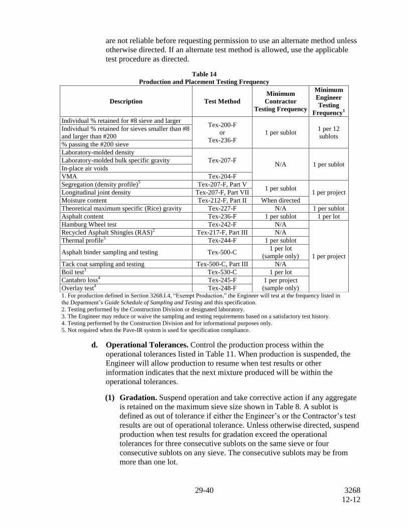
are not reliable before requesting permission to use an alternate method unless
otherwise directed. If an alternate test method is allowed, use the applicable
test procedure as directed.
Table 14
Production and Placement Testing Frequency
Description Test Method
Minimum
Contractor
Testing Frequency
Minimum
Engineer
Testing
Frequency1
Individual % retained for #8 sieve and larger Tex-200-F
or
Tex-236-F
1 per sublot 1 per 12
sublots
Individual % retained for sieves smaller than #8
and larger than #200
% passing the #200 sieve
Laboratory-molded density
Tex-207-F N/A 1 per sublot
Laboratory-molded bulk specific gravity
In-place air voids
VMA Tex-204-F
Segregation (density profile)5 Tex-207-F, Part V
1 per sublot 1 per project Longitudinal joint density Tex-207-F, Part VII
Moisture content Tex-212-F, Part II When directed
Theoretical maximum specific (Rice) gravity Tex-227-F N/A 1 per sublot
Asphalt content Tex-236-F 1 per sublot 1 per lot
Hamburg Wheel test Tex-242-F N/A
1 per project
Recycled Asphalt Shingles (RAS)2 Tex-217-F, Part III N/A
Thermal profile5 Tex-244-F 1 per sublot
Asphalt binder sampling and testing Tex-500-C 1 per lot
(sample only)
Tack coat sampling and testing Tex-500-C, Part III N/A
Boil test3 Tex-530-C 1 per lot
Cantabro loss4 Tex-245-F 1 per project
(sample only) Overlay test4 Tex-248-F
1. For production defined in Section 3268.I.4, “Exempt Production,” the Engineer will test at the frequency listed in
the Department’s Guide Schedule of Sampling and Testing and this specification.
2. Testing performed by the Construction Division or designated laboratory.
3. The Engineer may reduce or waive the sampling and testing requirements based on a satisfactory test history.
4. Testing performed by the Construction Division and for informational purposes only.
5. Not required when the Pave-IR system is used for specification compliance.
d. Operational Tolerances. Control the production process within the
operational tolerances listed in Table 11. When production is suspended, the
Engineer will allow production to resume when test results or other
information indicates that the next mixture produced will be within the
operational tolerances.
(1) Gradation. Suspend operation and take corrective action if any aggregate
is retained on the maximum sieve size shown in Table 8. A sublot is
defined as out of tolerance if either the Engineer’s or the Contractor’s test
results are out of operational tolerance. Unless otherwise directed, suspend
production when test results for gradation exceed the operational
tolerances for three consecutive sublots on the same sieve or four
consecutive sublots on any sieve. The consecutive sublots may be from
more than one lot.
30-40 3268
12-12
(2) Asphalt Content. A sublot is defined as out of operational tolerance if
either the Engineer’s or the Contractor’s test results exceed the values
listed in Table 11. No production or placement bonus will be paid for any
sublot that is out of operational tolerance for asphalt content. Suspend
production and shipment of the mixture if the Engineer’s or the
Contractor’s asphalt content deviates from the current JMF by more than
0.5% for any sublot.
(3) Voids in Mineral Aggregates (VMA). The Engineer will determine the
VMA for every sublot. For sublots when the Engineer does not determine
asphalt content, the Engineer will use the asphalt content results from
quality control testing performed by the Contractor to determine VMA.
Take immediate corrective action if the VMA value for any sublot is less
than the minimum VMA requirement for production listed in Table 8.
Suspend production and shipment of the mixture if the Engineer’s VMA
results on two consecutive sublots are below the minimum VMA
requirement for production listed in Table 8. No production or placement
bonus will be paid for any sublot that does not meet the minimum VMA
requirement for production listed in Table 8 based on the Engineer’s VMA
determination.
Suspend production and shipment of the mixture if the Engineer’s VMA
result is more than 0.5% below the minimum VMA requirement for
production listed in Table 8. In addition to suspending production, the
Engineer may require removal and replacement or may allow the sublot to
be left in place without payment.
(4) Hamburg Wheel Test. The Engineer may perform a Hamburg Wheel test
at any time during production, including when the boil test indicates a
change in quality from the materials submitted for JMF1. In addition to
testing production samples, the Engineer may obtain cores and perform
Hamburg Wheel tests on any areas of the roadway where rutting is
observed. When the production or core samples fail the Hamburg Wheel
test criteria in Table 10, suspend production until further Hamburg Wheel
tests meet the specified values. Core samples, if taken, will be obtained
from the center of the finished mat or other areas excluding the vehicle
wheel paths. The Engineer may require up to the entire sublot of any
mixture failing the Hamburg Wheel test to be removed and replaced at the
Contractor’s expense.
If the Department’s or approved laboratory’s Hamburg Wheel test results
in a “remove and replace” condition, the Contractor may request that the
Department confirm the results by retesting the failing material. The
Construction Division will perform the Hamburg Wheel tests and
determine the final disposition of the material in question based on the
Department’s test results.
31-40 3268
12-12
e. Individual Loads of Hot Mix. The Engineer can reject individual truckloads
of hot mix. When a load of hot mix is rejected for reasons other than
temperature, contamination, or excessive uncoated particles, the Contractor
may request that the rejected load be tested. Make this request within 4 hr. of
rejection. The Engineer will sample and test the mixture. If test results are
within the operational tolerances shown in Table 11, payment will be made for
the load. If test results are not within operational tolerances, no payment will
be made for the load and the Engineer may require removal.
3. Placement Acceptance.
a. Placement Lot. A placement lot consists of four placement sublots. A
placement sublot consists of the area placed during a production sublot.
(1) Lot 1 Placement. Placement bonuses for Lot 1 will be in accordance with
Section 3268.6.B, “Placement Pay Adjustment Factors;” however, no
placement penalty will be assessed for any sublot placed in Lot 1 when the
in-place air voids are greater than or equal to 2.7% and less than or equal
to 9.9%. Remove and replace any sublot with in-place air voids less than
2.7% or greater than 9.9%.
(2) Incomplete Placement Lots. An incomplete placement lot consists of the
area placed as described in Section 3268.4.I.2.a(1), “Incomplete
Production Lots,” excluding areas defined in Section 3268.4.I.3.a(4),
“Miscellaneous Areas.” Placement sampling is required if the random
sample plan for production resulted in a sample being obtained from an
incomplete production sublot.
(3) Shoulders, Ramps, Etc. Shoulders, ramps, intersections, acceleration
lanes, deceleration lanes, and turn lanes are subject to in-place air void
determination unless designated on the plans as not eligible for in-place air
void determination. Intersections may be considered miscellaneous areas
when determined by the Engineer.
(4) Miscellaneous Areas. Miscellaneous areas include areas that typically
involve significant handwork or discontinuous paving operations, such as
temporary detours, driveways, mailbox turnouts, crossovers, gores, spot
level-up areas, and other similar areas. Temporary detours are subject to
in-place air void determination when shown on the plans. Miscellaneous
areas also include level-ups and thin overlays when the layer thickness
specified on the plans is less than the minimum untrimmed core height
eligible for testing shown in Table 12. The specified layer thickness is
based on the rate of 110 lb./sq. yd. for each inch of pavement unless
another rate is shown on the plans. Miscellaneous areas are not eligible for
random placement sampling locations. Compact miscellaneous areas in
accordance with Section 3268.4.H, “Compaction.” Miscellaneous areas are
not subject to in-place air void determination, thermal profiles testing,
segregation (density profiles), or longitudinal joint density evaluations.
32-40 3268
12-12
b. Placement Sampling. At the beginning of the project, the Engineer will select
random numbers for all placement sublots. The Engineer will provide the
Contractor with the placement random numbers immediately after the sublot is
completed. Mark the roadway location at the completion of each sublot and
record the station number. Determine one random sample location for each
placement sublot in accordance with Tex-225-F. If the randomly generated
sample location is within 2 ft. of a joint or pavement edge, adjust the location
by no more than necessary to achieve a 2-ft. clearance.
Shoulders, ramps, intersections, acceleration lanes, deceleration lanes, and turn
lanes are always eligible for selection as a random sample location; however, if
a random sample location falls on one of these areas and the area is designated
on the plans as not subject to in-place air void determination, cores will not be
taken for the sublot and a 1.000 pay factor will be assigned to that sublot.
Provide the equipment and means to obtain and trim roadway cores on site.
On site is defined as in close proximity to where the cores are taken. Obtain the
cores within 1 working day of the time the placement sublot is completed
unless otherwise approved. Obtain two 6-in. diameter cores side-by-side from
within 1 ft. of the random location provided for the placement sublot. For Type
D and Type F mixtures, 4-in. diameter cores are allowed. Mark the cores for
identification, measure and record the untrimmed core height, and provide the
information to the Engineer. The Engineer will witness the coring operation
and measurement of the core thickness. Visually inspect each core and verify
that the current paving layer is bonded to the underlying layer. If an adequate
bond does not exist between the current and underlying layer, take corrective
action to ensure that an adequate bond will be achieved during subsequent
placement operations.
Immediately after obtaining the cores from the roadway, trim the cores in
accordance with Tex-207-F if the core heights meet the minimum untrimmed
values listed in Table 12. Trim the cores on site in the presence of the
Engineer. Use a permanent marker or paint pen to record the lot and sublot
numbers on each core as well as the designation as Core A or B. The Engineer
may require additional information to be marked on the core and may choose
to sign or initial the core. The Engineer will take custody of the cores
immediately after they are trimmed and will retain custody of the cores until
the Department’s testing is completed. Prior to turning the trimmed cores over
to the Engineer, the Contractor may elect to wrap the trimmed cores or secure
them in a manner that will reduce the risk of possible damage occurring during
transport by the Engineer. After testing, the Engineer will return the cores to
the Contractor.
The Engineer may elect to have the cores transported back to the Department’s
laboratory at the HMA plant via the Contractor’s haul truck or other designated
vehicle. In such cases where the cores will be out of the Engineer’s possession
during transport, the Engineer will use the Construction Division’s protocol to
provide a secure means and process that protects the integrity of the cores
during transport.
33-40 3268
12-12
If the core height before trimming is less than the minimum untrimmed value
shown in Table 12, decide whether to include the pair of cores in the air void
determination for that sublot. If electing to have the cores included in air void
determination, trim the cores as described above before delivering to the
Engineer. If electing to not have the cores included in air void determination,
deliver untrimmed cores to the Engineer and inform the Engineer of the
decision to not have the cores included in air void determination. The
placement pay factor for the sublot will be 1.000 if cores will not be included
in air void determination.
In lieu of the Contractor trimming the cores on site immediately after coring,
the Engineer and the Contractor may mutually agree to have the trimming
operations performed at an alternate location such as a field laboratory or other
similar location. In such cases, the Engineer will take possession of the cores
immediately after they are obtained from the roadway and will retain custody
of the cores until testing is completed. Either the Department or Contractor
representative may perform trimming of the cores. The Engineer will witness
all trimming operations in cases where the Contractor representative performs
the trimming operation.
Immediately after obtaining the cores, dry the core holes and tack the sides and
bottom. Fill the hole with the same type of mixture and properly compact the
mixture. Repair core holes with other methods when approved.
c. Placement Testing. Perform placement tests in accordance with Table 14.
After the Engineer returns the cores, the Contractor has the option to test the
cores to verify the Engineer’s test results for in-place air voids. The allowable
differences between the Contractor’s and Engineer’s test results are listed in
Table 11.
(1) In-Place Air Voids. The Engineer will measure in-place air voids in
accordance with Tex-207-F and Tex-227-F. Before drying to a constant
weight, cores may be pre-dried using a Corelok or similar vacuum device
to remove excess moisture. The Engineer will average the values obtained
for all sublots in the production lot to determine the theoretical maximum
specific gravity. The Engineer will use the average air void content for in-
place air voids.
The Engineer will use the vacuum method to seal the core if required by
Tex-207-F. The Engineer will use the test results from the unsealed core to
determine the placement pay adjustment factor if the sealed core yields a
higher specific gravity than the unsealed core. After determining the in-
place air void content, the Engineer will return the cores and provide test
results to the Contractor.
(2) Segregation (Density Profile). Test for segregation using density profiles
in accordance with Tex-207-F, Part V. Density profiles are not required
and are not applicable when using the Pave-IR system for specification
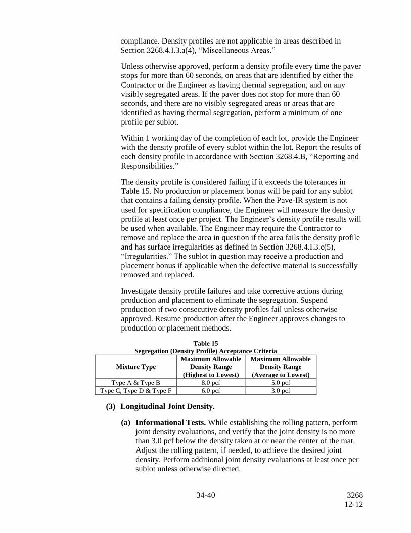
34-40 3268
12-12
compliance. Density profiles are not applicable in areas described in
Section 3268.4.I.3.a(4), “Miscellaneous Areas.”
Unless otherwise approved, perform a density profile every time the paver
stops for more than 60 seconds, on areas that are identified by either the
Contractor or the Engineer as having thermal segregation, and on any
visibly segregated areas. If the paver does not stop for more than 60
seconds, and there are no visibly segregated areas or areas that are
identified as having thermal segregation, perform a minimum of one
profile per sublot.
Within 1 working day of the completion of each lot, provide the Engineer
with the density profile of every sublot within the lot. Report the results of
each density profile in accordance with Section 3268.4.B, “Reporting and
Responsibilities.”
The density profile is considered failing if it exceeds the tolerances in
Table 15. No production or placement bonus will be paid for any sublot
that contains a failing density profile. When the Pave-IR system is not
used for specification compliance, the Engineer will measure the density
profile at least once per project. The Engineer’s density profile results will
be used when available. The Engineer may require the Contractor to
remove and replace the area in question if the area fails the density profile
and has surface irregularities as defined in Section 3268.4.I.3.c(5),
“Irregularities.” The sublot in question may receive a production and
placement bonus if applicable when the defective material is successfully
removed and replaced.
Investigate density profile failures and take corrective actions during
production and placement to eliminate the segregation. Suspend
production if two consecutive density profiles fail unless otherwise
approved. Resume production after the Engineer approves changes to
production or placement methods.
Table 15
Segregation (Density Profile) Acceptance Criteria
Mixture Type
Maximum Allowable
Density Range
(Highest to Lowest)
Maximum Allowable
Density Range
(Average to Lowest)
Type A & Type B 8.0 pcf 5.0 pcf
Type C, Type D & Type F 6.0 pcf 3.0 pcf
(3) Longitudinal Joint Density.
(a) Informational Tests. While establishing the rolling pattern, perform
joint density evaluations, and verify that the joint density is no more
than 3.0 pcf below the density taken at or near the center of the mat.
Adjust the rolling pattern, if needed, to achieve the desired joint
density. Perform additional joint density evaluations at least once per
sublot unless otherwise directed.
35-40 3268
12-12
(b) Record Tests. For each sublot, perform a joint density evaluation at
each pavement edge that is or will become a longitudinal joint. Joint
density evaluations are not applicable in areas described in
Section 3268.4.I.3.a(4), “Miscellaneous Areas.” Determine the joint
density in accordance with Tex-207-F, Part VII. Record the joint
density information and submit results on Department forms to the
Engineer. The evaluation is considered failing if the joint density is
more than 3.0 pcf below the density taken at the core random sample
location and the correlated joint density is less than 90.0%. The
Engineer will make an independent joint density verification at least
once per project and may make independent joint density verifications
at the random sample locations. The Engineer’s joint density test
results will be used when available.
Within 1 working day of the completion of each lot, provide the
Engineer with the joint density of every sublot within the lot. Report
the results of each joint density in accordance with Section 3268.4.B,
“Reporting and Responsibilities.”
Investigate joint density failures and take corrective actions during
production and placement to improve the joint density. Suspend
production if the evaluations on two consecutive sublots fail unless
otherwise approved. Resume production after the Engineer approves
changes to production or placement methods.
(4) Recovered Asphalt Dynamic Shear Rheometer (DSR). When the
Pave-IR system is not used for specification compliance, the Engineer may
take production samples or cores from suspect areas of the project to
determine recovered asphalt properties. Asphalt binders with an aging
ratio greater than 3.5 do not meet the requirements for recovered asphalt
properties and may be deemed defective when tested and evaluated by the
Construction Division. The aging ratio is the DSR value of the extracted
binder divided by the DSR value of the original unaged binder. Obtain
DSR values in accordance with AASHTO T 315 at the specified high
temperature performance grade of the asphalt. The Engineer may require
removal and replacement of the defective material at the Contractor’s
expense. The asphalt binder will be recovered for testing from production
samples or cores in accordance with Tex-211-F.
(5) Irregularities. Identify and correct irregularities including but not limited
to segregation, rutting, raveling, flushing, fat spots, mat slippage, irregular
color, irregular texture, roller marks, tears, gouges, streaks, uncoated
aggregate particles, or broken aggregate particles. The Engineer may also
identify irregularities, and in such cases, the Engineer will promptly notify
the Contractor. If the Engineer determines that the irregularity will
adversely affect pavement performance, the Engineer may require the
Contractor to remove and replace (at the Contractor’s expense) areas of the
pavement that contain irregularities and areas where the mixture does not
bond to the existing pavement.
36-40 3268
12-12
If irregularities are detected, the Engineer may require the Contractor to
immediately suspend operations or may allow the Contractor to continue
operations for no more than 1 day while the Contractor is taking
appropriate corrective action.
4. Exempt Production. When the anticipated daily production is less than 1,000 tons,
the total production for the project is less than 5,000 tons, or when mutually agreed
between the Engineer and the Contractor, the Engineer may deem the mixture as
exempt production. Production may also be exempt when shown on the plans.
For exempt production, the Contractor is relieved of all production and placement
sampling and testing requirements, and the production and placement pay factors
are 1.000. All other specification requirements apply, and the Engineer will
perform acceptance tests for production and placement listed in Table 14 at the
frequency listed in the Department’s Guide Schedule of Sampling and Testing.
For exempt production:
produce, haul, place, and compact the mixture in compliance with the
specification and as directed by the Engineer;
control mixture production to yield a laboratory-molded density that is within ±
1.0% of the target laboratory-molded density as tested by the Engineer;
compact the mixture in accordance with Section 3268.4.H, “Compaction”; and
when the Contractor elects not to use the Pave-IR system for specification
compliance, the Engineer may perform segregation (density profiles) and
thermal profiles in accordance with the specification.
5. Ride Quality. Measure ride quality in accordance with Item 585, “Ride Quality for
Pavement Surfaces,” unless otherwise shown on the plans.
5. Measurement. Hot mix will be measured by the ton of composite hot mix, which includes
asphalt, aggregate, and additives. Measure the weight on scales in accordance with Item 520,
“Weighing and Measuring Equipment.”
6. Payment. The work performed and materials furnished in accordance with this Item and
measured as provided under Article 3268.5, “Measurement,” will be paid for at the unit
price bid for “Dense Graded Hot-Mix Asphalt” of the type, surface aggregate classification,
and binder specified. These prices are full compensation for surface preparation; materials
including tack coat; placement; equipment; labor; tools; and incidentals.
Pay adjustments for bonuses and penalties will be applied as determined in this Item;
however, a pay adjustment factor of 1.000 will be assigned for all placement sublots for
“level ups” only when “level up” is listed as part of the item bid description code. A pay
adjustment factor of 1.000 will be assigned to all production and placement sublots when
“exempt” is listed as part of the item bid description code.
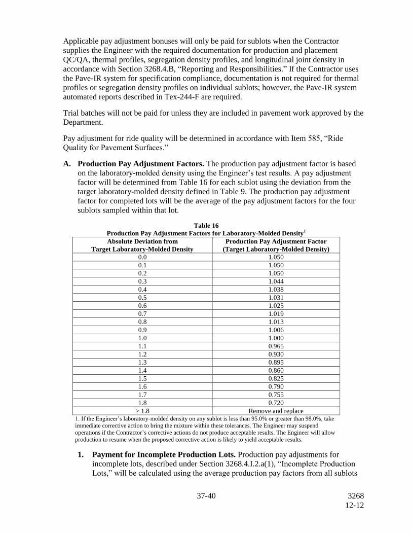
37-40 3268
12-12
Applicable pay adjustment bonuses will only be paid for sublots when the Contractor
supplies the Engineer with the required documentation for production and placement
QC/QA, thermal profiles, segregation density profiles, and longitudinal joint density in
accordance with Section 3268.4.B, “Reporting and Responsibilities.” If the Contractor uses
the Pave-IR system for specification compliance, documentation is not required for thermal
profiles or segregation density profiles on individual sublots; however, the Pave-IR system
automated reports described in Tex-244-F are required.
Trial batches will not be paid for unless they are included in pavement work approved by the
Department.
Pay adjustment for ride quality will be determined in accordance with Item 585, “Ride
Quality for Pavement Surfaces.”
A. Production Pay Adjustment Factors. The production pay adjustment factor is based
on the laboratory-molded density using the Engineer’s test results. A pay adjustment
factor will be determined from Table 16 for each sublot using the deviation from the
target laboratory-molded density defined in Table 9. The production pay adjustment
factor for completed lots will be the average of the pay adjustment factors for the four
sublots sampled within that lot.
Table 16
Production Pay Adjustment Factors for Laboratory-Molded Density1
Absolute Deviation from
Target Laboratory-Molded Density
Production Pay Adjustment Factor
(Target Laboratory-Molded Density)
0.0 1.050
0.1 1.050
0.2 1.050
0.3 1.044
0.4 1.038
0.5 1.031
0.6 1.025
0.7 1.019
0.8 1.013
0.9 1.006
1.0 1.000
1.1 0.965
1.2 0.930
1.3 0.895
1.4 0.860
1.5 0.825
1.6 0.790
1.7 0.755
1.8 0.720
> 1.8 Remove and replace 1. If the Engineer’s laboratory-molded density on any sublot is less than 95.0% or greater than 98.0%, take
immediate corrective action to bring the mixture within these tolerances. The Engineer may suspend
operations if the Contractor’s corrective actions do not produce acceptable results. The Engineer will allow
production to resume when the proposed corrective action is likely to yield acceptable results.
1. Payment for Incomplete Production Lots. Production pay adjustments for
incomplete lots, described under Section 3268.4.I.2.a(1), “Incomplete Production
Lots,” will be calculated using the average production pay factors from all sublots
38-40 3268
12-12
sampled. A production pay factor of 1.000 will be assigned to any lot when the
random sampling plan did not result in collection of any samples.
2. Production Sublots Subject to Removal and Replacement. If after referee
testing, the laboratory-molded density for any sublot results in a “remove and
replace” condition as listed in Table 16, the Engineer may require removal and
replacement, or may allow the sublot to be left in place without payment. The
Engineer may also elect to accept the sublot in accordance with Item 5, “Control of
the Work,” Section 5.3.A, “Acceptance of Defective or Unauthorized Work.”
Replacement material meeting the requirements of this Item will be paid for in
accordance with this Section.
B. Placement Pay Adjustment Factors. The placement pay adjustment factor is based on
in-place air voids using the Engineer’s test results. A pay adjustment factor will be
determined from Table 17 for each sublot that requires in-place air void measurement.
A placement pay adjustment factor of 1.000 will be assigned to the entire sublot when
the random sample location falls in an area designated on the plans as not subject to in-
place air void determination. A placement pay adjustment factor of 1.000 will be
assigned to quantities placed in areas described in Section 3268.4.I.3.a(4),
“Miscellaneous Areas.” The placement pay adjustment factor for completed lots will be
the average of the placement pay adjustment factors for up to four sublots within that
lot.
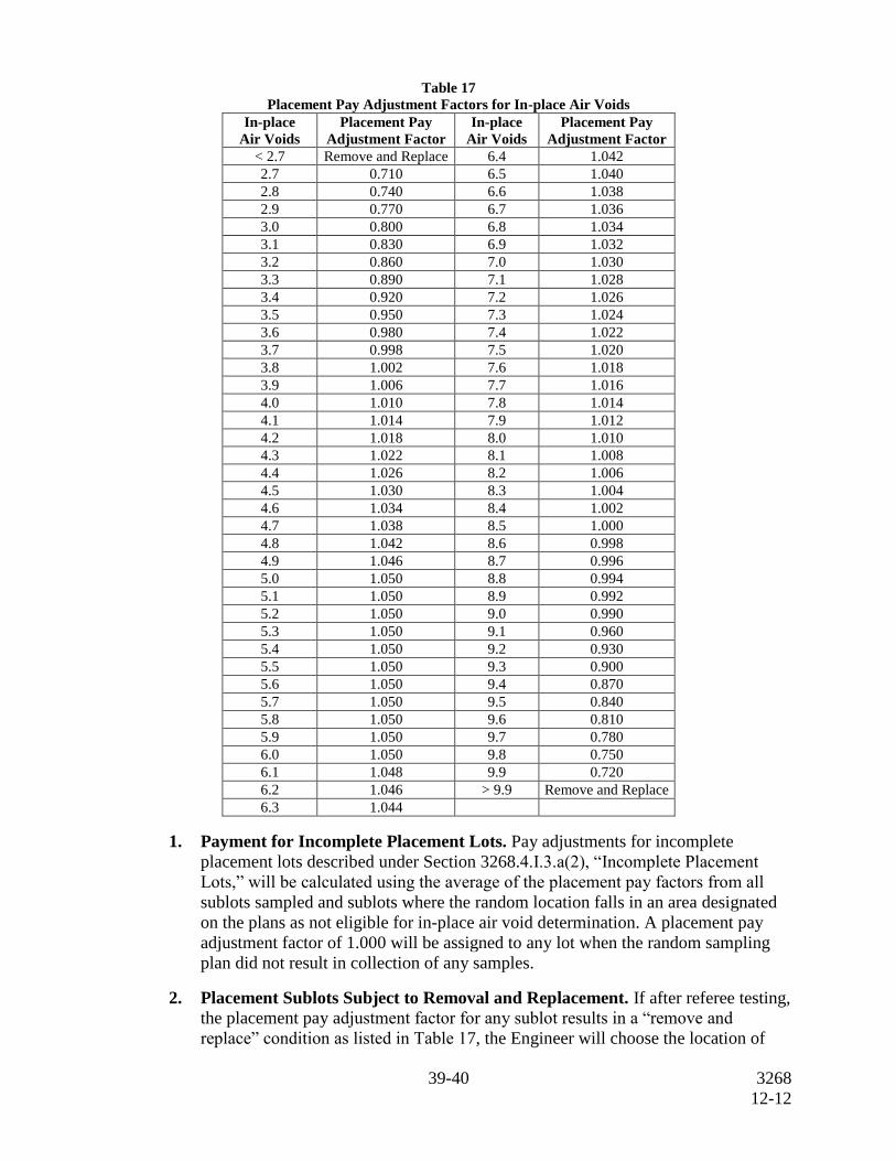
39-40 3268
12-12
Table 17
Placement Pay Adjustment Factors for In-place Air Voids
In-place
Air Voids
Placement Pay
Adjustment Factor
In-place
Air Voids
Placement Pay
Adjustment Factor
< 2.7 Remove and Replace 6.4 1.042
2.7 0.710 6.5 1.040
2.8 0.740 6.6 1.038
2.9 0.770 6.7 1.036
3.0 0.800 6.8 1.034
3.1 0.830 6.9 1.032
3.2 0.860 7.0 1.030
3.3 0.890 7.1 1.028
3.4 0.920 7.2 1.026
3.5 0.950 7.3 1.024
3.6 0.980 7.4 1.022
3.7 0.998 7.5 1.020
3.8 1.002 7.6 1.018
3.9 1.006 7.7 1.016
4.0 1.010 7.8 1.014
4.1 1.014 7.9 1.012
4.2 1.018 8.0 1.010
4.3 1.022 8.1 1.008
4.4 1.026 8.2 1.006
4.5 1.030 8.3 1.004
4.6 1.034 8.4 1.002
4.7 1.038 8.5 1.000
4.8 1.042 8.6 0.998
4.9 1.046 8.7 0.996
5.0 1.050 8.8 0.994
5.1 1.050 8.9 0.992
5.2 1.050 9.0 0.990
5.3 1.050 9.1 0.960
5.4 1.050 9.2 0.930
5.5 1.050 9.3 0.900
5.6 1.050 9.4 0.870
5.7 1.050 9.5 0.840
5.8 1.050 9.6 0.810
5.9 1.050 9.7 0.780
6.0 1.050 9.8 0.750
6.1 1.048 9.9 0.720
6.2 1.046 > 9.9 Remove and Replace
6.3 1.044
1. Payment for Incomplete Placement Lots. Pay adjustments for incomplete
placement lots described under Section 3268.4.I.3.a(2), “Incomplete Placement
Lots,” will be calculated using the average of the placement pay factors from all
sublots sampled and sublots where the random location falls in an area designated
on the plans as not eligible for in-place air void determination. A placement pay
adjustment factor of 1.000 will be assigned to any lot when the random sampling
plan did not result in collection of any samples.
2. Placement Sublots Subject to Removal and Replacement. If after referee testing,
the placement pay adjustment factor for any sublot results in a “remove and
replace” condition as listed in Table 17, the Engineer will choose the location of
40-40 3268
12-12
two cores to be taken within 3 ft. of the original failing core location. The
Contractor will obtain the cores in the presence of the Engineer. The Engineer will
take immediate possession of the untrimmed cores and submit the untrimmed cores
to the Construction Division, where they will be trimmed if necessary and tested
for bulk specific gravity within 10 working days of receipt. The average bulk
specific gravity of the cores will be divided by the Engineer’s average maximum
theoretical specific gravity for that lot to determine the new pay adjustment factor
of the sublot in question. If the new pay adjustment factor is 0.700 or greater, the
new pay adjustment factor will apply to that sublot. If the new pay adjustment
factor is less than 0.700, no payment will be made for the sublot. Remove and
replace the failing sublot, or the Engineer may allow the sublot to be left in place
without payment. The Engineer may also elect to accept the sublot in accordance
with Item 5, “Control of the Work,” Section 5.3.A “Acceptance of Defective or
Unauthorized Work.” Replacement material meeting the requirements of this Item
will be paid for in accordance with this Section.
C. Total Adjusted Pay Calculation. Total adjusted pay (TAP) will be based on the
applicable pay adjustment factors for production and placement for each lot.
TAP = (A+B)/2
where:
A = Bid price × production lot quantity × average pay adjustment factor for the
production lot
B = Bid price × placement lot quantity × average pay adjustment factor for the
placement lot + (bid price × quantity placed in miscellaneous areas × 1.000)
Production lot quantity = Quantity actually placed - quantity left in place without
payment
Placement lot quantity = Quantity actually placed - quantity left in place without
payment - quantity placed in miscellaneous areas


