

Power-Fast®+
Powers USA: (800) 524-3244 or (914) 235-6300 Canada: (905) 673-7295 or (514) 631-4216 www.powers.com 209
SPECIFICATION & DESIGN MANUAL
Power-Fast®+ Epoxy Adhesive Anchoring System
PRODUCT DESCRIPTIONThe Power-Fast+ Epoxy adhesive system is a two-component structural epoxy which is packagedin engineered plastic cartridges. It is used with either a manual, pneumatic or power-operatedinjection tool and proportionally mixed through a static-element mixing nozzle. Power-Fast+ is a premium, non-sag, high strength epoxy which has been vigorously tested to meet or exceedrequired standards as an anchoring and bonding adhesive. Power-Fast+ is available in Fast Setand Standard Set formulas.
Power-Fast+ Epoxy, formerly known as Rawl Foil-Fast, is designed for use in anchoring threadedrods, bolts, reinforcing bars, and smooth dowels into concrete and masonry base materials. The system can also be used to anchor into hollow masonry materials using rod and rebarwith screen tubes. In addition to anchoring applications, Power-Fast+ is used for bonding steeland cured concrete to cured concrete, for pick proofing applications, for surface sealing cracksand for placing injection ports.
GENERAL APPLICATIONS AND USES• Heavy duty anchoring such as rebar, threaded anchor rod, and threaded bolts in solid
concrete, grout filled block, stone, masonry, etc.• Used in wet environments, moderate to high temperatures and whenever solvent
or styrene fumes are not acceptable• Anchoring with screen tubes in hollow block or brick• High strength bonding to concrete, steel, wood, etc.• Optimal for unreinforced masonry (URM) retrofit projects• Ideal for crack sealing and port placement prior to epoxy resin crack injection• Commonly used for pick-proof applications in prison and security projects
FEATURES AND BENEFITS• Listed and approved to resist dead loads, live loads, and short-term loads such as those
resulting from wind or earthquake• Non-shrink, non-sag, moisture tolerant, high strength, structural epoxy gel• 100% solids, styrene and solvent-free, low odor, smooth paste formulation• The plus symbol “+” in Power-Fast+ designates a nozzle is packaged with each cartridge
(except for Jumbo cartridge packaging)• Available in five cartridge sizes to match project and application• Excellent resistance to chemicals• Meets the requirements of ASTM C881, Types I, II, IV and V, Grade 3• Meets current building code and DOT requirements• Suitable for oversized and diamond cored holes• Independently tested and qualified to ASTM E1512, AC58 and AC60 criteria, including
creep resistance, freeze-thaw cycling and simulated seismic/wind conditions
APPROVALS AND LISTINGSInternational Code Council, Evaluation Service (ICC-ES) ESR-1531
(formerly listed in ICBO ES ER-4514)Southern Building Code Conference International (SBCCI) #9943ACity of Los Angeles (COLA) Research Report LARR-25230City of Los Angeles (COLA) Research Report LARR-24979 for Unreinforced Masonry (URM)Florida Building Code Approval – FL2209.05Miami-Dade County Notice of Acceptance (NOA) 04-0823.06ANSI/NSF 61 – Drinking Water System Components CompliantMeets ASTM C881 and AASHTO M235Various North American Departments of Transportation (DOT) – See www.powers.com
GUIDE SPECIFICATIONSCSI Divisions: 03151-Concrete Anchoring, 04081-Masonry Anchorage and 05090-MetalFastening. Epoxy adhesive system shall be standard set or fast set Power-Fast+ as suppliedby Powers Fasteners, Inc., Brewster, NY.
AD
HES
IVES
MEC
HAN
ICA
LAN
CH
OR
S
WA
LL
AN
CH
OR
S
POW
DER
AC
TUA
TED
GA
S FA
STEN
ING
RO
OFIN
G
FAST
ENER
S
CA
RB
IDE
DR
ILL
BIT
S
SECTION CONTENTS Page No.
General Information.................. 209
Material and InstallationSpecifications ............................. 210
Installation Guidelines.............. 211
Steel Specifications ................... 212
Performance Data...................... 213
Design Criteria ........................... 223
Ordering Information................ 226
Power-Fast+ Coaxial Cartridge
Power-Fast+ Dual Cartridge
PACKAGING
Coaxial Cartridge10 fl. oz. (295 ml or 18.0 in3)
Dual (Side-by-Side) Cartridge15 fl. oz. (440 ml or 27.1 in3)22 fl. oz. (650 ml or 39.7 in3)44 fl. oz. (1300 ml or 79.4 in3)56 fl. oz. (1650 ml or 101.0 in3)
ANCHOR SIZE RANGE (TYP.)
1/4" to 1-1/2" diameter rodNo.3 to No.11 reinforcing bar3/4" to 1-1/2" smooth dowel bar3/8" to 3/4" internally threaded inserts
SUITABLE BASE MATERIALS
Normal-Weight ConcreteStructural Lightweight ConcreteGrouted Concrete MasonryHollow CMUBrick MasonryStone

Shelf Life 2 years for componentsStorage Conditions Store dry at 40° to 90°F
Injection Temperature For best results, condition materialto 60°F min.
ColorComponent A – WhiteComponent B – Dark Gray
Mixing Ratio 1:1 by volumeMixed Consistency Smooth, non-sag, uniform gray pasteShore Hardness D 86 – 90(ASTM D2240)Compressive Strength 11,125 psi, 1 day(ASTM D 695) 14,740 psi, 7 daysTensile Strength 7,250 psi, Fast Set(ASTM D 638) 7,400 psi, Standard SetFlexural Strength 6,200 psi, Fast Set(ASTM D 790) 6,700 psi, Standard SetSlant Shear Strength 4,900 psi, Fast Set – 1 day(ASTM D732) 6,700 psi, Standard Set – 14 dayWater Absorption Less than 1% (0.59%)(ASTM D 570)Bond Strength 3,000 psi, concrete to concrete(Dry cure) 3,000 psi, steel to concreteShrinkage Not measurable(ASTM D 2566)Heat Deflection 140°F (60°C)(ASTM D 648)
Reinforcing Bar Sizes, d Property No. 3 No. 4 No. 5 No. 6 No. 7 No. 8 No. 9 No. 10 No. 11d = Nominal bar diameter (inch) 3/8 1/2 5/8 3/4 7/8 1 1 1/8 1 1/4 1 3/8def = Effective anchor diameter (inch) 0.375 0.500 0.625 0.750 0.875 1.000 1.128 1.270 1.410Abr = Nominal area of reinforcing bar (inch2) 0.110 0.200 0.310 0.440 0.600 0.790 1.000 1.270 1.560dbit = Nominal bit diameter (inch) 1/2 5/8 3/4 7/8 1 1 1/8 1 1/4 1 1/2 1 5/8
Rod Diameter, d (in.)Property 1/4 3/8 1/2 5/8 3/4 7/8 1 1 1/4 1 3/8 1 1/2Anom = Nominal area of threaded rod (inch2) 0.0491 0.1105 0.1963 0.3068 0.4418 0.6013 0.7854 1.2272 1.4840 1.7660Ase = Tensile stress area of rod (inch2) 0.0318 0.0775 0.1419 0.2260 0.3345 0.4617 0.6057 0.9691 1.1549 1.4053dbit = Nominal bit diameter (inch) 5/16 7/16 9/16 3/4 7/8 1 1 1/8 1 3/8 1 1/2 1 5/8Tmax = Max. tightening 4d < hv < 9d 2-3 7-8 17-20 25-30 40-45 65-75 100-110 160-175 210-235 275-300
torque range (ft.-lbs.) hv > 9d 4-5 15-17 35-40 70-80 120-130 185-200 275-300 375-425 500-550 650-725
MATERIAL AND INSTALLATION SPECIFICATIONS
AD
HESIV
ES
MEC
HAN
ICA
LAN
CH
OR
S
WA
LL AN
CH
OR
S
POW
DER
AC
TUA
TED
GA
S FA
STENIN
G
RO
OFIN
G
FASTEN
ERS
CA
RB
IDE
DR
ILL BITS
SPECIFICATION & DESIGN MANUAL Power-Fast®+
www.powers.com Canada: (905) 673-7295 or (514) 631-4216 Powers USA: (800) 524-3244 or (914) 235-6300 210
40 30 60 8 16 36 4860 20 45 3 7 24 3675 15 35 2 6 24 2490 10 20 1 1/2 4 16 24
°C = 5/9 (°F-32)
Std.Set
FastSet
Std.Set
FastSet
Std.Set
FastSet
BaseMaterial
Temp.(°F)
Maximum Gel Time1,2
(Minutes)
Minimum Curing Time2,3
(Hours)
Full Curing Time4
(Hours)
1. The gel time is the maximum time during which the epoxy can be worked before it begins to harden.2. Anchors must not be disturbed between the maximum gel time and the minimum curing time.3. The Power-Fast+ adhesive can support the weight of the anchor element (not including any fixture)
at half of the minimum cure time.4. The full curing time is the minimum time required for the epoxy to harden and achieve its
ultimate load capacities.Anchors may not be tightened until the full curing time has elapsed.
Installation Specifications
Nomenclature
d = Diameter of rod or rebardbit = Diameter of drill bith = Base material thickness.
The minimum value of h should be 1.5hv
hv = Minimum embedment depthl = Overall length of rod or rebart = Fixture thicknessTmax = Maximum tightening torque
(Only possible after full cure)
MATERIAL AND INSTALLATION SPECIFICATIONS
Physical Properties for Adhesive Setting Times

Power-Fast®+
Powers USA: (800) 524-3244 or (914) 235-6300 Canada: (905) 673-7295 or (514) 631-4216 www.powers.com 211
AD
HES
IVES
MEC
HAN
ICA
LAN
CH
OR
S
WA
LL
AN
CH
OR
S
POW
DER
AC
TUA
TED
GA
S FA
STEN
ING
RO
OFIN
G
FAST
ENER
S
CA
RB
IDE
DR
ILL
BIT
S
SPECIFICATION & DESIGN MANUAL
INSTALLATION GUIDELINES
Drill a hole to the size and embedment required. The tolerances of the drill bit used should meet therequirements of ANSI StandardB212.15.
Starting from the bottom or back of the anchor hole, blow clean with compressed air for a minimum of four seconds,brush the hole with a nylonbrush a minimum of fourtimes, and blow it clean again. Vacuuming only is notsufficient. Blow out bulbs generally do not provide enough dustremoval for most drilled anchor holes. Holes should be clean andsound. They may be dry or damp, but should be free of standingwater or frost. If using reinforcing bar, be sure the bar will fit intothe drilled hole. If a larger hole is required, the diameter shouldbe as close as possible to the diameter of the reinforcing bar.
Prior to dispensing intoanchor hole, balance thecartridge and visuallyinspect that adhesivecomponents are uniformlymixed. Fill the holeapproximately half to two-thirds full with adhesive starting from the bottom or backof the anchor hole. Slowly withdraw the static mixing nozzle asthe hole fills to avoid creating air pockets.
Push the threaded rod orreinforcing bar into the anchorhole while turning slightly toensure positive distribution ofthe adhesive. Be sure the rod is fully seated at the bottom of the hole and that someadhesive has flowed from the top of the hole. The threaded rodor reinforcing bar used should be free of dirt, grease, oil orother foreign material.
Allow the adhesive to cure for the specified time prior to applying any load. Do notdisturb, torque, or load theanchor until it is fully cured.
Drill a hole to the size andembedment for the requiredscreen size. The tolerances of the drill bit used shouldmeet the requirements ofANSI B212.15.
Starting from the bottom or back of the anchor hole,blow the hole clean with compressed air for a minimum of four seconds, brush the hole with a nylon brush aminimum of four times, and blow it clean again.Vacuuming only is not sufficient. Blow out bulbs generally donot provide enough dust removal for drilled anchor holes inhollow base materials.
Prior to dispensing into screen tube, balance thecartridge and visuallyinspect that adhesivecomponents are uniformlymixed. Fill the screen tubewith adhesive starting fromthe bottom of the screen. The screen tube should becompletely filled prior to inserting it in the anchor hole.
Insert the filled screen tubeinto the anchor hole until it is fully seated at therequired embedment.
Push the threaded rod into the screen while turningslightly to ensure positivedispensing of the adhesive. Be sure the rod is fully inserteddown to the end of the screentube. The threaded rod orreinforcing bar used should be free of dirt, grease, oil, or otherforeign material.
Allow the adhesive to cure for the specified time prior to applying any load. Do notdisturb, torque, or load theanchor until it is fully cured.
Solid Base Materials Hollow Base Materials
Prior to use, read product label, Material Safety Data Sheet and injection tool instructions.Do not install in base materials with temperature below 40 degrees F.

1/4(6.4)3/8
(9.5)1/2
(12.7)5/8
(15.9)3/4
(19.1)7/8
(22.2)1
(25.4)1 1/4(31.8)1 3/8(34.9)1 1/2(38.1)
AD
HESIV
ES
MEC
HAN
ICA
LAN
CH
OR
S
WA
LL AN
CH
OR
S
POW
DER
AC
TUA
TED
GA
S FA
STENIN
G
RO
OFIN
G
FASTEN
ERS
CA
RB
IDE
DR
ILL BITS
SPECIFICATION & DESIGN MANUAL Power-Fast®+
www.powers.com Canada: (905) 673-7295 or (514) 631-4216 Powers USA: (800) 524-3244 or (914) 235-6300 212
Note:Allowable design load must be the lesser of allowable steel strength (as shown on this page) and the allowable bond capacities.
Allowable steel strength values for threaded rod are based on the following equations:
T = 0.33 * fu * Anom
V = 0.17 * fu * Anom
And, the allowable steel strength values for reinforcing bar are based on the following equations:
T = fs * Abr
V = 0.17 * fs * Abr
Where:T = Allowable tension load (pounds).V = Allowable shear load (pounds).fu = Minimum specified ultimate stress (psi)fs = Allowable tensile stress of reinforcement bar (psi)Anom = Nominal cross-sectional area of threaded rod (in2).Abr = Nominal cross-sectional area of reinforcing bar (in2).
Material Properties for Threaded Rod and Reinforcing Bar
Allowable Steel Strength Capacities for Threaded Rod
AnchorType
Threaded Rod
Reinforcing Bar
Steel Description
Standard carbon rod
High strength carbon rod
Grade 40 RebarGrade 60 Rebar
Steel Specification(ASTM)
A36A 307, Grade CA 193, Grade B7
A 615, A 616, A 617,A 706 or A 767
F 593, Condition CW
Rod Dia. or RebarSize (inch or No.)
3/4 thru 1 1/2
All
Minimum YieldStrength, fy (ksi)
36.036.0105.0
Stainless Rod(Type 304 / 316 SS) 85.0
60.0
65.0
40.045.0
Minimum UltimateStrength, fu (ksi)
58.058.0
90.0
120.0100.0
70.0
3/8 thru 43/8 thru 2 1/23/8 thru 5/8
All
940(4.2)2,115(9.5)3,755(16.9)5,870(26.4)8,455(38.0)11,510(51.8)15,035(67.7)23,485(105.7)28,400(127.8)33,800(152.1)
940(4.2)2,115(9.5)3,755(16.9)5,870(26.4)8,455(38.0)11,510(51.8)15,035(67.7)23,485(105.7)28,400(127.8)33,800(152.1)
2,160(9.7)4,375(19.7)7,775(35.0)12,150(54.7)17,495(78.7)23,810(107.1)31,100(140.0)48,560(218.5)58,760(264.4)69,930(314.7)
1,210(5.4)3,630(16.3)6,470(29.1)10,130(45.6)12,400(55.8)16,860(75.9)22,020(99.1)34,420(154.9)41,625(187.3)49,535(222.9)
485(2.2)1,090(4.9)1,940(8.7)3,025(13.6)4,355(19.6)5,930(26.7)7,745(34.9)12,100(54.5)14,630(65.8)17,410(78.3)
485(2.2)1,090(4.9)1,940(8.7)3,025(13.6)4,355(19.6)5,930(26.7)7,745(34.9)12,100(54.5)14,630(65.8)17,410(78.3)
1,030(4.6)2,255(10.1)4,055(18.2)6,260(28.2)9,010(40.5)12,265(55.2)16,020(72.1)25,035(112.7)30,270(136.2)36,025(162.1)
625(2.8)1,870(8.4)3,330(15.0)5,210(23.4)6,390(28.8)8,680(39.1)11,340(51.0)17,730(79.8)21,440(96.5)25,515(114.8)
Allowable Tension Allowable Shear
ASTMA36
lbs.(kN)
ASTMA307
Grade Clbs.(kN)
ASTMA193
Grade B7lbs.(kN)
ASTMF593
304/316 SSlbs.(kN)
ASTMA36
lbs.(kN)
ASTMA307
Grade Clbs.(kN)
ASTMA193
Grade B7lbs.(kN)
ASTMF593
304/316 SSlbs.(kN)
AnchorDiameter
din.
(mm)
Allowable Steel Strength Capacities for Reinforcing Bar
2,200(9.9)4,000(18.0)6,200(27.9)8,800(39.6)12,000(54.0)15,800(71.1)20,000(90.0)25,400(114.3)31,200(140.4)
No. 3(3/8")No. 4(1/2")No. 5 (5/8")No. 6(3/4")No. 7(7/8")No. 8(1")
No. 9(1 1/8")No. 10
(1 1/4")No. 11
(1 3/8")
2,640(11.9)4,800(21.6)7,440(33.5)10,560(47.5)14,400(64.8)18,960(85.3)24,000(108.0)30,480(137.2)37,440(168.5)
1,310(5.9)2,380(10.7)3,690(16.6)5,235(23.6)7,140(32.1)9,400(42.3)11,900(53.6)15,115(68.0)16,920(76.1)
1,680(7.6)3,060(13.8)4,740(21.3)6,730(30.3)9,180(41.3)12,085(54.4)15,300(68.9)19,430(87.4)20,305(91.4)
Tension lbs.(kN)
Shear lbs.(kN)
BarSize
Grade 40 Grade 60 Grade 40 Grade 60
STEEL SPECIFICATIONS
Steel strength capacities are based on the design criteria listed in the AISC Manual of Steel Construction.
Steel strength capacities are based on the requirements of ASTM A 615.

Minimum Concrete Compressive Strength (f c )
1. Ultimate load capacities are listed for the Standard Set formula and should be reduced by a minimum safety factor of 4.0 or greater to determine the allowable working load.2. Reduce the above ultimate load values by 25 percent when calculating ultimate load capacities for the Fast Set formula.3. Linear interpolation may be used to determine ultimate load capacities for intermediate embedments and compressive strengths.
1/4(6.4)
3/8(9.5)
1/2(12.7)
5/8(15.9)
3/4(19.1)
7/8(22.2)
1(25.4)
1 1/4(31.8)
1 3/8 (34.9)
1 1/2(38.1)
5/16
7/16
9/16
3/4
7/8
1
1 1/8
1 3/8
1 1/2
1 5/8
1 1,400 2,465 1,500 2,465 1,600 2,465 1,905 2,465(25.4) (6.3) (11.1) (6.8) (11.1) (7.2) (11.1) (8.6) (11.1)
2 2,370 2,465 2,660 2,465 2,950 2,465 3,685 2,465(50.8) (10.7) (11.1) (12.0) (11.1) (13.3) (11.1) (16.6) (11.1)
3 3,860 2,465 4,165 2,465 4,470 2,465 5,355 2,465(76.2) (17.4) (11.1) (18.7) (11.1) (20.1) (11.1) (24.1) (11.1)1 1/2 3,460 4,600 3,920 4,600 4,400 4,600 5,200 4,600(38.1) (15.6) (20.7) (17.6) (20.7) (19.8) (20.7) (23.4) (20.7)3 3/8 9,560 6,000 11,040 6,000 11,780 6,000 12,520 6,000(85.7) (43.0) (27.0) (49.7) (27.0) (53.0) (27.0) (56.3) (27.0)5 1/4 14,000 6,480 15,380 6,480 15,560 6,480 15,640 6,480
(133.4) (63.0) (29.2) (69.2) (29.2) (70.0) (29.2) (70.4) (29.2)2 4,800 6,800 7,240 6,800 10,820 6,800 14,460 6,800
(50.8) (21.6) (30.6) (32.6) (30.6) (48.7) (30.6) (65.1) (30.6)4 1/2 12,980 12,800 13,600 12,800 18,860 12,800 21,760 12,800
(114.3) (58.4) (57.6) (61.2) (57.6) (84.9) (57.6) (97.9) (57.6)7 20,880 12,800 24,380 12,800 26,440 12,800 28,500 12,800
(177.8) (94.0) (57.6) (109.7) (57.6) (119.0) (57.6) (128.3) (57.6)2 1/2 6,900 9,600 8,280 9,600 9,400 9,600 10,500 9,600(63.5) (31.1) (43.2) (37.3) (43.2) (42.3) (43.2) (47.3) (43.2)5 5/8 19,340 22,800 22,240 22,800 23,400 22,800 24,580 22,800
(142.9) (87.0) (102.6) (100.1) (102.6) (105.3) (102.6) (110.6) (102.6)8 3/4 30,820 22,800 32,040 22,800 36,760 22,800 38,280 22,800
(222.3) (138.7) (102.6) (144.2) (102.6) (165.4) (102.6) (172.3) (102.6)3 9,600 14,400 12,200 14,400 14,840 14,400 17,440 14,400
(76.2) (43.2) (64.8) (54.9) (64.8) (66.8) (64.8) (78.5) (64.8)6 3/4 28,160 25,600 33,480 25,600 37,520 25,600 43,080 25,600
(171.5) (126.7) (115.2) (150.7) (115.2) (168.8) (115.2) (193.9) (115.2)10 1/2 39,760 29,250 45,520 29,250 47,680 29,250 49,800 29,250(266.7) (178.9) (131.6) (204.8) (131.6) (214.6) (131.6) (224.1) (131.6)3 1/2 10,920 14,000 13,320 14,000 15,580 14,000 17,820 14,000(88.9) (49.1) (63.0) (59.9) (63.0) (70.1) (63.0) (80.2) (63.0)7 7/8 32,680 36,800 38,400 36,800 42,160 36,800 45,900 36,800
(200.0) (147.1) (165.6) (172.8) (165.6) (189.7) (165.6) (206.6) (165.6)12 1/4 52,360 36,800 61,440 36,800 67,240 36,800 73,000 36,800(311.2) (235.6) (165.6) (276.5) (165.6) (302.6) (165.6) (328.5) (165.6)
4 13,540 18,400 16,340 18,400 18,780 18,400 21,200 18,400(101.6) (60.9) (82.8) (73.5) (82.8) (84.5) (82.8) (95.4) (82.8)
9 39,760 50,000 48,520 50,000 56,740 50,000 64,920 50,000(228.6) (178.9) (225.0) (218.3) (225.0) (255.3) (225.0) (292.1) (225.0)
14 58,900 53,135 68,760 53,135 74,600 53,135 80,420 53,135(355.6) (265.1) (239.1) (309.4) (239.1) (335.7) (239.1) (361.9) (239.1)
5 18,000 22,000 24,080 22,000 30,760 22,000 38,780 22,000(127.0) (81.0) (99.0) (108.4) (99.0) (138.4) (99.0) (174.5) (99.0)11 1/4 52,920 72,000 66,800 72,000 83,920 72,000 100,900 72,000(285.8) (238.1) (324.0) (300.6) (324.0) (377.6) (324.0) (454.1) (324.0)17 1/2 91,480 83,450 109,240 83,450 123,280 83,450 137,240 83,450(444.5) (411.7) (375.5) (491.6) (375.5) (554.8) (375.5) (617.6) (375.5)5 1/2 30,330 47,980 36,610 47,980 42,890 47,980 49,550 47,980
(139.7) (136.5) (215.9) (164.7) (215.9) (193.0) (215.9) (223.0) (215.9)12 3/8 68,250 78,905 82,375 78,905 96,500 78,905 111,490 78,905(314.3) (307.1) (355.1) (370.7) (355.1) (434.3) (355.1) (501.7) (355.1)16 1/2 90,995 97,460 109,825 97,460 128,660 97,460 148,650 97,460(419.1) (409.5) (438.6) (494.2) (438.6) (579.0) (438.6) (668.9) (438.6)
6 35,760 55,520 43,160 55,520 50,560 55,520 58,415 55,520(152.4) (160.9) (249.8) (194.2) (249.8) (227.5) (249.8) (262.9) (249.8)13 1/2 80,455 91,305 97,105 91,305 113,760 91,305 131,430 91,305(342.9) (362.0) (410.9) (437.0) (410.9) (511.9) (410.9) (591.4) (410.9)
18 107,275 112,780 129,475 112,780 151,680 112,780 167,245 112,780(457.2) (482.7) (507.5) (582.6) (507.5) (682.6) (507.5) (752.6) (507.5)
Min.Embed.Depth
hvin.
(mm)
RodDiameter
din.
(mm)
DrillBitDia.dbitin.
Tension Shear Tension Shear Tension Shear Tension Shearlbs. lbs. lbs. lbs. lbs. lbs. lbs. lbs.(kN) (kN) (kN) (kN) (kN) (kN) (kN) (kN)
2,000 psi (13.8 MPa) 3,000 psi (20.7 MPa) 4,000 psi (27.6 MPa) 5,000 psi (34.5 MPa)
PERFORMANCE DATA
Ultimate Bond Strength Capacities for Threaded Rod Installed with Power-Fast+ in Normal-Weight Concrete1,2,3
Power-Fast®+
Powers USA: (800) 524-3244 or (914) 235-6300 Canada: (905) 673-7295 or (514) 631-4216 www.powers.com 213
AD
HES
IVES
MEC
HAN
ICA
LAN
CH
OR
S
WA
LL
AN
CH
OR
S
POW
DER
AC
TUA
TED
GA
S FA
STEN
ING
RO
OFIN
G
FAST
ENER
S
CA
RB
IDE
DR
ILL
BIT
S
SPECIFICATION & DESIGN MANUAL

1 350 615 375 615 400 615 475 615(25.4) (1.6) (2.8) (1.7) (2.8) (1.8) (2.8) (2.1) (2.8)
2 595 615 665 615 740 615 920 615(50.8) (2.7) (2.8) (3.0) (2.8) (3.3) (2.8) (4.1) (2.8)
3 965 615 1,040 615 1,120 615 1,340 615(76.2) (4.3) (2.8) (4.7) (2.8) (5.0) (2.8) (6.0) (2.8)1 1/2 865 1,150 980 1,150 1,100 1,150 1,300 1,150(38.1) (3.9) (5.2) (4.4) (5.2) (5.0) (5.2) (5.9) (5.2)3 3/8 2,390 1,500 2,760 1,500 2,945 1,500 3,130 1,500(85.7) (10.8) (6.8) (12.4) (6.8) (13.3) (6.8) (14.1) (6.8)5 1/4 3,500 1,620 3,845 1,620 3,890 1,620 3,910 1,620
(133.4) (15.8) (7.3) (17.3) (7.3) (17.5) (7.3) (17.6) (7.3)2 1,200 1,700 1,810 1,700 2,705 1,700 3,615 1,700
(50.8) (5.4) (7.7) (8.1) (7.7) (12.2) (7.7) (16.3) (7.7)4 1/2 3,245 3,200 3,400 3,200 4,715 3,200 5,440 3,200
(114.3) (14.6) (14.4) (15.3) (14.4) (21.2) (14.4) (24.5) (14.4)7 5,220 3,200 6,095 3,200 6,610 3,200 7,125 3,200
(177.8) (23.5) (14.4) (27.4) (14.4) (29.7) (14.4) (32.1) (14.4)2 1/2 1,725 2,400 2,070 2,400 2,350 2,400 2,625 2,400(63.5) (7.8) (10.8) (9.3) (10.8) (10.6) (10.8) (11.8) (10.8)5 5/8 4,835 5,700 5,560 5,700 5,850 5,700 6,145 5,700
(142.9) (21.8) (25.7) (25.0) (25.7) (26.3) (25.7) (27.7) (25.7)8 3/4 7,705 5,700 8,010 5,700 9,190 5,700 9,570 5,700
(222.3) (34.7) (25.7) (36.0) (25.7) (41.4) (25.7) (43.1) (25.7)3 2,400 3,600 3,050 3,600 3,710 3,600 4,360 3,600
(76.2) (10.8) (16.2) (13.7) (16.2) (16.7) (16.2) (19.6) (16.2)6 3/4 7,040 6,400 8,370 6,400 9,380 6,400 10,770 6,400
(171.5) (31.7) (28.8) (37.7) (28.8) (42.2) (28.8) (48.5) (28.8)10 1/2 9,940 7,315 11,380 7,315 11,920 7,315 12,450 7,315(266.7) (44.7) (32.9) (51.2) (32.9) (53.6) (32.9) (56.0) (32.9)3 1/2 2,730 3,500 3,330 3,500 3,895 3,500 4,455 3,500(88.9) (12.3) (15.8) (15.0) (15.8) (17.5) (15.8) (20.0) (15.8)7 7/8 8,170 9,200 9,600 9,200 10,540 9,200 11,475 9,200
(200.0) (36.8) (41.4) (43.2) (41.4) (47.4) (41.4) (51.6) (41.4)12 1/4 13,090 9,200 15,360 9,200 16,810 9,200 18,250 9,200(311.2) (58.9) (41.4) (69.1) (41.4) (75.6) (41.4) (82.1) (41.4)
4 3,385 4,600 4,085 4,600 4,695 4,600 5,300 4,600(101.6) (15.2) (20.7) (18.4) (20.7) (21.1) (20.7) (23.9) (20.7)
9 9,940 12,500 12,130 12,500 14,185 12,500 16,230 12,500(228.6) (44.7) (56.3) (54.6) (56.3) (63.8) (56.3) (73.0) (56.3)
14 14,725 13,285 17,190 13,285 18,650 13,285 20,105 13,285(355.6) (66.3) (59.8) (77.4) (59.8) (83.9) (59.8) (90.5) (59.8)
5 4,500 5,500 6,020 5,500 7,690 5,500 9,695 5,500(127.0) (20.3) (24.8) (27.1) (24.8) (34.6) (24.8) (43.6) (24.8)11 1/4 13,230 18,000 16,700 18,000 20,980 18,000 25,225 18,000(285.8) (59.5) (81.0) (75.2) (81.0) (94.4) (81.0) (113.5) (81.0)17 1/2 22,870 20,865 27,310 20,865 30,820 20,865 34,310 20,865(444.5) (102.9) (93.9) (122.9) (93.9) (138.7) (93.9) (154.4) (93.9)5 1/2 7,585 11,995 9,155 11,995 10,725 11,995 12,390 11,995
(139.7) (34.1) (54.0) (41.2) (54.0) (48.3) (54.0) (55.8) (54.0)12 3/8 17,065 19,725 20,595 19,725 24,125 19,725 27,875 19,725(314.3) (76.8) (88.8) (92.7) (88.8) (108.6) (88.8) (125.4) (88.8)16 1/2 22,750 24,365 27,455 24,365 32,165 24,365 37,165 24,365(419.1) (102.4) (109.6) (123.5) (109.6) (144.7) (109.6) (167.2) (109.6)
6 8,940 13,880 10,790 13,880 12,640 13,880 14,605 13,880(152.4) (40.2) (62.5) (48.6) (62.5) (56.9) (62.5) (65.7) (62.5)13 1/2 20,115 22,825 24,275 22,825 28,440 22,825 32,860 22,825(342.9) (90.5) (102.7) (109.2) (102.7) (128.0) (102.7) (147.9) (102.7)
18 26,820 28,195 32,370 28,195 37,920 28,195 41,810 28,195(457.2) (120.7) (126.9) (145.7) (126.9) (170.6) (126.9) (188.1) (126.9)
AD
HESIV
ES
MEC
HAN
ICA
LAN
CH
OR
S
WA
LL AN
CH
OR
S
POW
DER
AC
TUA
TED
GA
S FA
STENIN
G
RO
OFIN
G
FASTEN
ERS
CA
RB
IDE
DR
ILL BITS
SPECIFICATION & DESIGN MANUAL Power-Fast®+
www.powers.com Canada: (905) 673-7295 or (514) 631-4216 Powers USA: (800) 524-3244 or (914) 235-6300 214
Minimum Concrete Compressive Strength (f c )
1. Allowable bond capacities listed are for the Standard Set formula and are calculated using an applied safety factor of 4.0.2. Reduce the above allowable bond capacities by 25 percent when calculating allowable bond capacities for the Fast Set formula.3. Linear interpolation may be used to determine allowable bond capacities for intermediate embedments and compressive strengths.4. Allowable design load should be the lesser of the bond or allowable steel strength.5. Allowable loads for threaded rods to resist short-term loads such as earthquake or wind may be increased by 33-1/3 percent for the duration of the load, where permitted by code.
1/4(6.4)
3/8(9.5)
1/2(12.7)
5/8(15.9)
3/4(19.1)
7/8(22.2)
1(25.4)
1 1/4(31.8)
1 3/8 (34.9)
1 1/2(38.1)
5/16
7/16
9/16
3/4
7/8
1
1 1/8
1 3/8
1 1/2
1 5/8
Min.Embed.Depth
hvin.
(mm)
RodDiameter
din.
(mm)
DrillBitDia.dbitin.
Tension Shear Tension Shear Tension Shear Tension Shearlbs. lbs. lbs. lbs. lbs. lbs. lbs. lbs.(kN) (kN) (kN) (kN) (kN) (kN) (kN) (kN)
2,000 psi (13.8 MPa) 3,000 psi (20.7 MPa) 4,000 psi (27.6 MPa) 5,000 psi (34.5 MPa)
PERFORMANCE DATA
Allowable Bond Strength Capacities for Threaded Rod Installed with Power-Fast+ in Normal-Weight Concrete1,2,3,4,5
PERFORMANCE DATA

RodDia.
din.
(mm)
3,295(14.8)
3,555(16.0)
3,815(17.2)
4,080(17.2)
4,340(19.5)
4,600(20.7)
4,550(20.5)
5,055(22.7)
5,560(25.0)
6,065(27.3)
6,570(29.6)
7,075(31.8)
6,135(27.6)
6,960(31.3)
7,785(35.0)
8,605(38.7)
9,430(42.4)
10,255(46.1)
2,915(13.1)
3,170(14.3)
3,430(15.4)
3,690(15.4)
3,950(17.8)
4,210(18.9)
3,905(17.6)
4,375(19.7)
4,840(21.8)
5,310(23.9)
5,780(26.0)
6,250(28.1)
5,775(26.0)
6,500(29.3)
7,230(32.5)
7,955(35.8)
8,680(39.1)
9,410(42.3)
2,530(11.4)
2,790(12.6)
3,045(13.7)
3,305(13.7)
3,565(16.0)
3,820(17.2)
3,260(14.7)
3,690(16.6)
4,125(18.6)
4,560(20.5)
4,990(22.5)
5,420(24.4)
5,415(24.4)
6,045(27.2)
6,675(30.0)
7,300(32.9)
7,935(35.7)
8,560(38.5)
2,150(9.7)
2,405(10.8)
2,660(12.0)
2,915(12.0)
3,175(14.3)
3,430(15.4)
2,615(11.8)
3,010(13.5)
3,405(15.3)
3,805(17.1)
4,200(18.9)
4,595(20.7)
5,055(22.7)
5,585(25.1)
6,120(27.5)
6,650(29.9)
7,185(32.3)
7,715(34.7)
Towardsthe Free
Edge
Parallel tothe Free
Edge
Towardsthe Free
Edge
Parallel tothe Free
Edge
1 3/4(44.5)
1 3/4(44.5)
1 3/4(44.5)
7(177.8)
8 3/4(222.3)
12 1/4(311.2)
Power-Fast®+
Powers USA: (800) 524-3244 or (914) 235-6300 Canada: (905) 673-7295 or (514) 631-4216 www.powers.com 215
AD
HES
IVES
MEC
HAN
ICA
LAN
CH
OR
S
WA
LL
AN
CH
OR
S
POW
DER
AC
TUA
TED
GA
S FA
STEN
ING
RO
OFIN
G
FAST
ENER
S
CA
RB
IDE
DR
ILL
BIT
S
SPECIFICATION & DESIGN MANUAL
Minimum Concrete Compressive Strength(f c )
1/2(12.7)
5/8(15.9)
7/8(22.2)
9/16
3/4
1
Min.Embed.Depth
hvin.
(mm)
Min.EdgeDist.
in.(mm)
Min.EndDist.
in.(mm)
DrillBitDia.dbitin. 2,000 psi
(13.8 MPa)3,000 psi(20.7 MPa)
4,000 psi(27.6 MPa)
5,000 psi(34.5 MPa)
PERFORMANCE DATA
Allowable Bond Strength Capacities for Threaded Rod Installed with Power-Fast+ at 1-3/4" from Edge of Normal-Weight Concrete1,2,3,4,5
4 1/2(114.3)
5(127.0)
5 1/2(139.7)
6(139.7)
6 1/2(165.1)
7(177.8)
5 5/8(142.9)
6 1/4(158.8)
6 7/8(174.6)
7 1/2(190.5)
8 1/8(206.4)
8 3/4(222.3)
7 7/8(200.0)
8 3/4(222.3)
9 5/8(244.5)
10 1/2(266.7)
11 3/8(288.9)
12 1/4(311.2)
1,600(7.2)
2,260(10.2)
2,910(13.1)
620(2.8)
680(3.1)
1,020(4.6)
1,455(6.5)
2,060(9.3)
2,650(11.9)
565(2.5)
620(2.8)
930(4.2)
Tension, lbs. (kN) Shear, lbs. (kN)
f c = 2,000 psi(13.8 MPa)
f c ≥ 2,500 psi(17.2 MPa)
1. Allowable bond capacities listed are for the Standard Set formula and are calculated using an applied safety factor of 4.0.2. Reduce the above allowable bond capacities by 25 percent when calculating allowable bond capacities for the Fast Set formula.3. Linear interpolation may be used to determine allowable bond capacities for intermediate embedments and compressive strengths.4. Allowable design load should be the lesser of the bond or allowable steel strength.5. Allowable loads for threaded rods to resist short-term loads such as earthquake or wind may be increased by 33-1/3 percent for the duration of the load,
where permitted by code.

3/8(9.5)
1/2(12.7)
5/8(15.9)
3/4(19.1)
Tension Shear Tension Shearlbs. lbs. lbs. lbs.(kN) (kN) (kN) (kN)
2,830(12.7)
3,675(16.5)
3,730(16.8)
3,915(17.6)
3,835(17.3)
4,055(18.2)
4,890(22.0)
5,530(24.6)
6,565(29.5)
6,110(27.5)
7,880(35.5)
10,960(49.3)
15,600(70.2)
22,440(101.0)
1/2(12.7)
5/8(15.9)
3/4(19.1)
7/8(22.2)
1 1/2(38.1)
1 5/8(41.3)
2 3/8(60.3)
2 3/4(69.9)
5(127.0)
5(127.0)
5(127.0)
10(254.0)
5(127.0)
5(127.0)
5(127.0)
5(127.0)
10(254.0)
5(127.0)
1 3/4(44.5)
1 3/4(44.5)
1 3/4(44.5)
1 3/4(44.5)
6(152.4)
6(152.4)
6(152.4)
8(203.2)
7(177.8)
8 3/4(222.3)
10(254.0)
10(254.0)
12 1/2(317.5)
12 1/2(317.5)
12 1/4(311.2)
15(381.0)
15(381.0)
17 1/2(444.5)
AD
HESIV
ES
MEC
HAN
ICA
LAN
CH
OR
S
WA
LL AN
CH
OR
S
POW
DER
AC
TUA
TED
GA
S FA
STENIN
G
RO
OFIN
G
FASTEN
ERS
CA
RB
IDE
DR
ILL BITS
SPECIFICATION & DESIGN MANUAL Power-Fast®+
www.powers.com Canada: (905) 673-7295 or (514) 631-4216 Powers USA: (800) 524-3244 or (914) 235-6300 216
9/16
3/4
1
1 1/8
Ultimate Allowable
6,480(29.2)
11,120(50.0)
17,650(79.4)
29,250(131.6)
1,970(8.9)
2,740(12.3)
3,900(17.6)
5,610(25.2)
1,620(7.3)
2,780(12.5)
4,415(19.9)
7,315(32.9)
1. Allowable bond capacities listed are for the Standard Set formula and are calculated using an applied safety factor of 4.0.2. Reduce the above allowable bond capacities by 25 percent when calculating allowable bond capacities for the Fast Set formula.3. Allowable design load should be the lesser of the bond or allowable steel strength.4. Allowable loads for threaded rods to resist short-term loads such as earthquake or wind may be increased by 33-1/3 percent
for the duration of the load, where permitted by code.
1. Allowable bond capacities listed are for the Standard Set formula and are calculated using an applied safety factor of 4.0.2. Reduce the above allowable bond capacities by 25 percent when calculating allowable bond capacities for the Fast Set formula.3. Linear interpolation may be used to determine allowable bond capacities for intermediate embedments.4. Allowable design load should be the lesser of the bond or allowable steel strength.5. Allowable loads for threaded rods to resist short-term loads such as earthquake or wind may be increased by 33-1/3
percent for the duration of the load, where permitted by code.
f c ≥ 2,500 psi(17.2 MPa)
9/16
3/4
7/8
1
Min.Embed.Depth
hvin.
(mm)
Min.EdgeDist.
in.(mm)
Min.Wall
Widthwin.
(mm)
Min.EndDist.
in.(mm)
RodDiameter
din.
(mm)
DrillBit
Diameterdbitin.
PERFORMANCE DATA
Tensionlbs.(kN)
Allowable Bond Strength Capacities for Threaded Rod Installed with Power-Fast+ in Normal-Weight Concrete Stem Walls1,2,3,4,5
3 1/2(88.9)
4 1/4(108.0)
5(127.0)
6 5/8(168.3)
17/32(13.5)
21/32(16.7)
29/32(23.0)
1(25.4)
DrillBitDia.dbitin.
Min.Embed.Depth
hvin.
(mm)
ThreadDepth
in.(mm)
SteelInsert Size
din.
(mm)
OutsideDiameter
in.(mm)
Ultimate and Allowable Bond Strength Capacities for InternallyThreaded Inserts Installed with Power-Fast+ in Normal-WeightConcrete1,2,3,4
f c ≥ 4,000 psi(27.6 MPa)
Internally Threaded Insert
BarSize
No.(in.)
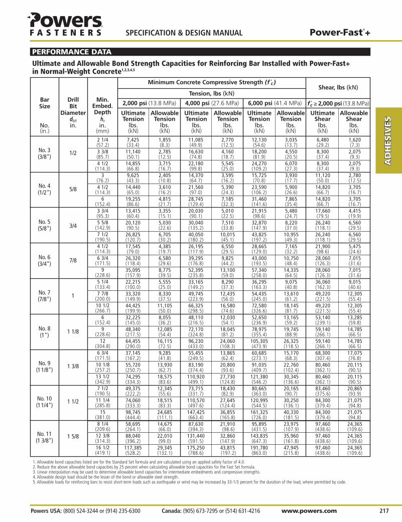
Shear, lbs (kN)
7,425 1,855 11,085 2,770 12,130 3,035 6,480 1,620(33.4) (8.3) (49.9) (12.5) (54.6) (13.7) (29.2) (7.3)11,140 2,785 16,630 4,160 18,200 4,550 8,300 2,075(50.1) (12.5) (74.8) (18.7) (81.9) (20.5) (37.4) (9.3)14,855 3,715 22,180 5,545 24,270 6,070 8,300 2,075(66.8) (16.7) (99.8) (25.0) (109.2) (27.3) (37.4) (9.3)9,625 2,405 14,370 3,595 15,725 3,930 11,120 2,780(43.3) (10.8) (64.7) (16.2) (70.8) (17.7) (50.0) (12.5)14,440 3,610 21,560 5,390 23,590 5,900 14,820 3,705(65.0) (16.2) (97.0) (24.3) (106.2) (26.6) (66.7) (16.7)19,255 4,815 28,745 7,185 31,460 7,865 14,820 3,705(86.6) (21.7) (129.4) (32.3) (141.6) (35.4) (66.7) (16.7)13,415 3,355 20,030 5,010 21,915 5,480 17,660 4,415(60.4) (15.1) (90.1) (22.5) (98.6) (24.7) (79.5) (19.9)20,120 5,030 30,040 7,510 32,870 8,220 26,240 6,560(90.5) (22.6) (135.2) (33.8) (147.9) (37.0) (118.1) (29.5)26,825 6,705 40,050 10,015 43,825 10,955 26,240 6,560(120.7) (30.2) (180.2) (45.1) (197.2) (49.3) (118.1) (29.5)17,545 4,385 26,195 6,550 28,665 7,165 21,900 5,475(79.0) (19.7) (117.9) (29.5) (129.0) (32.2) (98.6) (24.6)26,320 6,580 39,295 9,825 43,000 10,750 28,060 7,015(118.4) (29.6) (176.8) (44.2) (193.5) (48.4) (126.3) (31.6)35,095 8,775 52,395 13,100 57,340 14,335 28,060 7,015(157.9) (39.5) (235.8) (59.0) (258.0) (64.5) (126.3) (31.6)22,215 5,555 33,165 8,290 36,295 9,075 36,060 9,015(100.0) (25.0) (149.2) (37.3) (163.3) (40.8) (162.3) (40.6)33,320 8,330 49,745 12,435 54,435 13,610 49,220 12,305(149.9) (37.5) (223.9) (56.0) (245.0) (61.2) (221.5) (55.4)44,425 11,105 66,325 16,580 72,580 18,145 49,220 12,305(199.9) (50.0) (298.5) (74.6) (326.6) (81.7) (221.5) (55.4)32,225 8,055 48,110 12,030 52,650 13,165 53,140 13,285(145.0) (36.2) (216.5) (54.1) (236.9) (59.2) (239.1) (59.8)48,340 12,085 72,170 18,045 78,975 19,745 59,140 14,785(217.5) (54.4) (324.8) (81.2) (355.4) (88.9) (266.1) (66.5)64,455 16,115 96,230 24,060 105,305 26,325 59,140 14,785(290.0) (72.5) (433.0) (108.3) (473.9) (118.5) (266.1) (66.5)37,145 9,285 55,455 13,865 60,685 15,170 68,300 17,075(167.2) (41.8) (249.5) (62.4) (273.1) (68.3) (307.4) (76.8)55,720 13,930 83,190 20,800 91,035 22,760 80,460 20,115(250.7) (62.7) (374.4) (93.6) (409.7) (102.4) (362.1) (90.5)74,295 18,575 110,920 27,730 121,380 30,345 80,460 20,115(334.3) (83.6) (499.1) (124.8) (546.2) (136.6) (362.1) (90.5)49,375 12,345 73,715 18,430 80,665 20,165 83,460 20,865(222.2) (55.6) (331.7) (82.9) (363.0) (90.7) (375.6) (93.9)74,060 18,515 110,570 27,645 120,995 30,250 84,300 21,075(333.3) (83.3) (497.6) (124.4) (544.5) (136.1) (379.4) (94.8)98,745 24,685 147,425 36,855 161,325 40,330 84,300 21,075(444.4) (111.1) (663.4) (165.8) (726.0) (181.5) (379.4) (94.8)58,695 14,675 87,630 21,910 95,895 23,975 97,460 24,365(264.1) (66.0) (394.3) (98.6) (431.5) (107.9) (438.6) (109.6)88,040 22,010 131,440 32,860 143,835 35,960 97,460 24,365(396.2) (99.0) (591.5) (147.9) (647.3) (161.8) (438.6) (109.6)117,385 29,345 175,250 43,815 191,780 47,945 97,460 24,365(528.2) (132.1) (788.6) (197.2) (863.0) (215.8) (438.6) (109.6)
2 1/4(57.2)3 3/8(85.7)4 1/2
(114.3)3
(76.2)4 1/2
(114.3)6
(152.4)3 3/4(95.3)5 5/8
(142.9)7 1/2
(190.5)4 1/2
(114.3)6 3/4
(171.5)9
(228.6)5 1/4
(133.4)7 7/8
(200.0)10 1/2(266.7)
6(152.4)
9(228.6)
12(304.8)6 3/4
(171.5)10 1/8(257.2)13 1/2(342.9)7 1/2
(190.5)11 1/4(285.8)
15(381.0)8 1/4
(209.6)12 3/8(314.3)16 1/2(419.1)
No. 3(3/8")
No. 4(1/2")
No. 5(5/8")
No. 6(3/4")
No. 7(7/8")
No. 8(1")
No. 9(11/8")
No. 10(11/4")
No. 11 (1 3/8")
Minimum Concrete Compressive Strength (f c )
Tension, lbs (kN)
1. Allowable bond capacities listed are for the Standard Set formula and are calculated using an applied safety factor of 4.0.2. Reduce the above allowable bond capacities by 25 percent when calculating allowable bond capacities for the Fast Set formula.3. Linear interpolation may be used to determine allowable bond capacities for intermediate embedments and compressive strengths.4. Allowable design load should be the lesser of the bond or allowable steel strength.5. Allowable loads for reinforcing bars to resist short-term loads such as earthquake or wind may be increased by 33-1/3 percent for the duration of the load, where permitted by code.
1/2
5/8
3/4
7/8
1
1 1/8
1 3/8
1 1/2
1 5/8
Min.Embed.Depth
hvin.
(mm)
DrillBit
Diameterdbitin.
Ultimate Allowable Ultimate Allowable Ultimate Allowable Ultimate AllowableTension Tension Tension Tension Tension Tension Shear Shear
lbs. lbs. lbs. lbs. lbs. lbs. lbs. lbs.(kN) (kN) (kN) (kN) (kN) (kN) (kN) (kN)
2,000 psi (13.8 MPa) 4,000 psi (27.6 MPa) 6,000 psi (41.4 MPa) fc ≥ 2,000 psi (13.8 MPa)
PERFORMANCE DATA
Ultimate and Allowable Bond Strength Capacities for Reinforcing Bar Installed with Power-Fast+ in Normal-Weight Concrete1,2,3,4,5
Power-Fast®+
Powers USA: (800) 524-3244 or (914) 235-6300 Canada: (905) 673-7295 or (514) 631-4216 www.powers.com 217
AD
HES
IVES
MEC
HAN
ICA
LAN
CH
OR
S
WA
LL
AN
CH
OR
S
POW
DER
AC
TUA
TED
GA
S FA
STEN
ING
RO
OFIN
G
FAST
ENER
S
CA
RB
IDE
DR
ILL
BIT
S
SPECIFICATION & DESIGN MANUAL

AD
HESIV
ES
MEC
HAN
ICA
LAN
CH
OR
S
WA
LL AN
CH
OR
S
POW
DER
AC
TUA
TED
GA
S FA
STENIN
G
RO
OFIN
G
FASTEN
ERS
CA
RB
IDE
DR
ILL BITS
SPECIFICATION & DESIGN MANUAL Power-Fast®+
www.powers.com Canada: (905) 673-7295 or (514) 631-4216 Powers USA: (800) 524-3244 or (914) 235-6300 218
Grade 60 Rebar(fy=60 ksi,fu=90 ksi)
2 1/4 7,425 11,085 12,130(57.2) (33.4) (49.9) (54.6)
No. 3 1/2 3 3/8 11,140 2 3 16,630 1 3/8 2 18,200 1 1/4 1 7/8 6,600 9,900(3/8") (85.7) (50.1) (50.8) (76.2) (74.8) (34.0) (51.0) (81.9) (31.1) (46.7) (29.7) (44.6)
4 1/2 14,855 22,180 24,270(114.3) (66.8) (99.8) (109.2)
3 9,625 14,370 15,725(76.2) (43.3) (64.7) (70.8)
No. 4 5/8 4 1/2 14,440 3 3/4 5 5/8 21,560 2 1/2 3 3/4 23,590 2 1/2 3 3/8 12,000 18,000(1/2") (114.3) (65.0) (95.0) (142.5) (97.0) (63.6) (95.4) (106.2) (58.2) (87.2) (54.0) (81.0)
6 19,255 28,745 31,460(152.4) (86.6) (129.4) (141.6)3 3/4 13,415 20,030 21,915(95.3) (60.4) (90.1) (98.6)
No. 5 3/4 5 5/8 20,120 5 1/4 7 3/4 30,040 3 1/2 5 1/4 32,870 3 4 3/4 18,600 27,900(5/8") (142.9) (90.5) (132.1) (198.1) (135.2) (88.4) (132.7) (147.9) (80.8) (121.3) (83.7) (125.6)
7 1/2 26,825 40,050 43,825(190.5) (120.7) (180.2) (197.2)4 1/2 17,545 26,195 28,665
(114.3) (79.0) (117.9) (129.0)No. 6 7/8 6 3/4 26,320 6 3/4 10 1/4 39,295 4 1/2 6 3/4 43,000 4 6 1/4 26,400 39,600(3/4") (171.5) (118.4) (172.0) (257.9) (176.8) (115.2) (172.8) (193.5) (105.3) (157.9) (118.8) (178.2)
9 35,095 52,395 57,340(228.6) (157.9) (235.8) (258.0)5 1/4 22,215 33,165 36,295
(133.4) (100.0) (149.2) (163.3)No. 7 1 7 7/8 33,320 8 1/2 12 3/4 49,745 5 3/4 8 1/2 54,435 5 7 3/4 36,000 54,000(7/8") (200.0) (149.9) (216.1) (324.2) (223.9) (144.8) (217.1) (245.0) (132.3) (198.4) (162.0) (243.0)
10 1/2 44,425 66,325 72,580(266.7) (199.9) (298.5) (326.6)
6 32,225 48,110 52,650(152.4) (145.0) (216.5) (236.9)
No. 8 1 1/8 9 48,340 8 3/4 13 1/4 72,170 6 8 3/4 78,975 5 1/2 8 1/8 47,450 71,100(1") (228.6) (217.5) (224.4) (336.2) (324.8) (150.3) (225.2) (355.4) (137.3) (205.8) (213.5) (320.0)
12 64,455 96,230 105,305(304.8) (290.0) (433.0) (473.9)6 3/4 37,145 55,455 60,685
(171.5) (167.2) (249.5) (273.1)No. 9 1 3/8 10 1/8 55,720 11 16 1/4 83,190 7 1/4 11 91,035 6 1/2 10 60,000 90,000
(1 1/8") (257.2) (250.7) (276.9) (415.4) (374.4) (185.5) (278.2) (409.7) (169.5) (254.3) (270.0) (405.0)13 1/2 74,295 110,920 121,380(342.9) (334.3) (499.1) (546.2)7 1/2 49,375 73,715 80,665
(190.5) (222.2) (331.7) (363.0)No. 10 1 1/2 11 1/4 74,060 11 5/8 17 1/4 110,570 8 11 5/8 120,995 7 10 5/8 76,200 114,300
(1 1/4") (285.8) (333.3) (294.0) (441.0) (497.6) (196.9) (295.4) (544.5) (180.0) (269.9) (342.9) (514.4)15 98,745 147,425 161,325
(381.0) (444.4) (663.4) (726.0)8 1/4 58,695 87,630 95,895
(209.6) (264.1) (394.3) (431.5)No. 11 1 5/8 12 3/8 88,040 13 19 3/4 131,440 9 13 143,835 8 12 1/8 93,600 140,400
(1 3/8") (314.3) (396.2) (334.2) (501.3) (591.5) (223.8) (335.8) (647.3) (204.5) (306.8) (421.2) (631.8)16 1/2 117,385 175,250 191,780(419.1) (528.2) (788.6) (863.0)
TensionMinimum Concrete Compressive Strength (f c )
1. Ultimate bond strength capacities listed are for the Standard Set formula.2. Reduce the tabulated ultimate bond strength capacities by 25 percent for the Fast Set formula. Increase development lengths accordingly.3. Linear interpolation may be used to determine rebar development lengths for intermediate compressive strengths.
Min.Embed.Depth
hvin.
(mm)
BarSize
No.(in.)
DrillBitDia.dbitin.
Ultimate Embed.at Embed.at Ultimate Embed.at Embed.at Ultimate Embed.at Embed.at UltimateBond Yield Tensile Bond Yield Tensile Bond Yield Tensile Yield Tensile
Strength Strength Strength Strength Strength Strength Strength Strength Strength Strength Strengthlbs. in. in. lbs. in. in. lbs. in. in. lbs. lbs.(kN) (mm) (mm) (kN) (mm) (mm) (kN) (mm) (mm) (kN) (kN)
2,000 psi (13.8 MPa) 4,000 psi (27.6 MPa) 6,000 psi (41.4 MPa)
PERFORMANCE DATA
Minimum Development Lengths for Reinforcing Bar Installed with Power-Fast+ in Normal-Weight Concrete1,2,3

RodDiameter
din.
(mm)
Power-Fast®+
Powers USA: (800) 524-3244 or (914) 235-6300 Canada: (905) 673-7295 or (514) 631-4216 www.powers.com 219
AD
HES
IVES
MEC
HAN
ICA
LAN
CH
OR
S
WA
LL
AN
CH
OR
S
POW
DER
AC
TUA
TED
GA
S FA
STEN
ING
RO
OFIN
G
FAST
ENER
S
CA
RB
IDE
DR
ILL
BIT
S
SPECIFICATION & DESIGN MANUAL
Ultimate and Allowable Bond Strength Capacities for Threaded Rod Installed with Power-Fast+ in Structural Lightweight Concrete1,2,3,4,5
Ultimate Load Allowable Load
f c ≥ 3,000 psi (20.7 MPa)
Tension Shear Tension Shearlbs. lbs. lbs. lbs.(kN) (kN) (kN) (kN)
3/8(9.5)
1/2(12.7)
5/8(15.9)
7/16
9/16
3/4
Min.Embed.Depth
hvin.
(mm)
DrillBit
Diameterdbitin.
1 1/2(38.1)1 7/8(47.6)2 1/4(57.2)2 5/8(66.7)
3(76.2)3 3/8(85.7)
2(50.8)2 1/2(63.5)
3(76.2)3 1/2(88.9)
4(101.6)4 1/2(114.3)2 1/2(63.5)3 1/8(79.4)3 3/4(95.3)4 3/8
(111.1)5
(127.0)5 5/8
(142.9)
3,280 5,160 820 1,290(14.8) (23.2) (3.7) (5.8)4,300 5,220 1,075 1,305(19.4) (23.5) (4.8) (5.9)5,300 5,300 1,325 1,325(23.9) (23.9) (6.0) (6.0)6,320 5,360 1,580 1,340(28.4) (24.1) (7.1) (6.0)7,320 5,440 1,830 1,360(32.9) (24.5) (8.2) (6.1)8,340 5,500 2,085 1,375(37.5) (24.8) (9.4) (6.2)5,100 8,020 1,275 2,005(23.0) (36.1) (5.7) (9.0)6,740 8,320 1,685 2,080(30.3) (37.4) (7.6) (9.4)8,380 8,620 2,095 2,155(37.7) (38.8) (9.4) (9.7)
10,040 8,940 2,510 2,235(45.2) (40.2) (11.3) (10.1)
11,680 9,240 2,920 2,310(52.6) (41.6) (13.1) (10.4)
13,320 9,540 3,330 2,385(59.9) (42.9) (15.0) (10.7)6,880 11,440 1,720 2,860(31.0) (51.5) (7.7) (12.9)8,580 12,040 2,145 3,010(38.6) (54.2) (9.7) (13.5)
10,280 12,640 2,570 3,160(46.3) (56.9) (11.6) (14.2)
12,000 13,240 3,000 3,310(54.0) (59.6) (13.5) (14.9)
13,700 13,840 3,425 3,460(61.7) (62.3) (15.4) (15.6)
15,400 14,440 3,850 3,610(69.3) (65.0) (17.3) (16.2)
1. The values listed above are ultimate and allowable bond capacities for Power-Fast+ in sand-lightweight concrete.2. Allowable bond capacities listed are for the Standard Set formula and are calculated using an applied safety factor of 4.0.3. Reduce the above allowable bond capacities by 25 percent when calculating allowable bond capacities for the Fast Set formula.4. Linear interpolation may be used to determine allowable bond capacities for intermediate embedments. Allowable loads for intermediate spacing and edge distances may be calculated using
spacing and edge distance reduction factors in the Design Criteria section.5. Allowable design load should be the lesser of the bond or allowable steel strength.
Steel Strength
28,600 7,150 38,100 9,525 42,320 10,580 26,400 39,600(128.7) (32.2) (171.5) (42.9) (190.4) (47.6) (118.8) (178.2)36,800 9,200 48,980 12,245 54,420 13,605 26,400 39,600(165.6) (41.4) (220.4) (55.1) (244.9) (61.2) (118.8) (178.2)36,670 9,170 48,800 12,200 54,230 13,560 47,400 71,100(165.0) (41.3) (219.6) (54.9) (244.0) (61.0) (213.3) (320.0)47,150 11,790 62,750 15,690 69,730 17,435 47,400 71,100(212.2) (53.1) (282.4) (70.6) (313.8) (78.5) (213.3) (320.0)44,480 11,120 59,200 14,800 65,775 16,445 73,590 110,390(200.2) (50.0) (266.4) (66.6) (296.0) (74.0) (331.2) (496.8)57,180 14,295 76,100 19,025 84,560 21,140 73,590 110,390(257.3) (64.3) (342.5) (85.6) (380.5) (95.1) (331.2) (496.8)52,280 13,070 69,580 17,395 77,315 19,330 105,975 158,960(235.3) (58.8) (313.1) (78.3) (347.9) (87.0) (476.9) (715.3)67,200 16,800 89,460 22,365 99,400 24,850 105,975 158,960(302.4) (75.6) (402.6) (100.6) (447.3) (111.8) (476.9) (715.3)
7(177.8)
9(228.6)
7(177.8)
9(228.6)
7(177.8)
9(228.6)
7(177.8)
9(228.6)
3/4(19.1)
1(25.4)
1 1/4(31.8)
1 1/2(38.1)
Bond Strength
Minimum Concrete Compressive Strength (f c )
1. Allowable bond capacities listed are for the Standard Set formula and are calculated using an applied safety factor of 4.0.2. Reduce the above allowable bond capacities by 25 percent when calculating allowable bond capacities for the Fast Set formula.3. Linear interpolation may be used to determine allowable bond capacities for intermediate embedments and compressive strengths.4. Allowable design load should be the lesser of the bond or allowable steel strength.5. Allowable loads for reinforcing bars to resist short-term loads such as earthquake or wind may be increased by 33-1/3 percent for the duration of the load, where permitted by code.
7/8
1 1/8
1 3/8
1 5/8
Min.Embed.Depth
hvin.
(mm)
DowelSize
d
DrillBit
Diameterdbitin.
Ultimate Allowable Ultimate Allowable Ultimate Allowable Yield UltimateTension Tension Tension Tension Tension Tension Tension Tension
lbs. lbs. lbs. lbs. lbs. lbs. lbs. lbs.(kN) (kN) (kN) (kN) (kN) (kN) (kN) (kN)
2,000 psi (13.8 MPa) 4,000 psi (27.6 MPa) 6,000 psi (41.4 MPa) Grade 60 Dowel
PERFORMANCE DATA
Ultimate and Allowable Bond Strength Capacities for Smooth Dowel Bars Installed with Power-Fast+ in Normal-Weight Concrete1,2,3,4,5

Anchor Installed In Cell Opening (Top of Wall) For Sill Plates And Other Attachments
10 3/4(273.1)
10 3/4(273.1)
3/8(9.5)
1/2(12.7)
5/8(15.9)
1,030(4.6)
1,830(8.2)
2,290(10.3)
1,025(4.6)
1,325(6.0)
1,730(7.8)
3/8(9.5)
1/2(12.7)
5/8(15.9)
3 3/4(95.3)
12(304.8)
3 3/4(95.3)
12(304.8)
3 3/4(95.3)
12(304.8)
3 1/2(88.9)
4 1/4(108.0)
5(127.0)
Anchor Installed Through Face Shell
Perpen.to Edge
Parallelto Edge
1. Tabulated load values are for anchors installed in minimum Grade N, Type II, lightweight, medium-weight and normal-weight concrete masonry units conforming to ASTM C 90 that have reached the minimum designated ultimate compressive strength at the time of installation (f'm ≥ 1,500 psi).
2. Allowable bond capacities listed are for the Standard Set formula and are calculated using an applied safety factor of 5.0.3. Reduce the above allowable bond capacities by 25 percent when calculating allowable bond capacities for the Fast Set formula.4. Allowable design load should be the lesser of the bond or allowable steel strength.5. Allowable loads for threaded rods to resist short-term loads such as earthquake or wind may be increased by 33-1/3 percent
for the duration of the load, where permitted by code.6. The critical spacing is 16 anchor diameters for full capacity. The minimum spacing is 8 anchor diameters for 50 percent reduction
in load. Linear interpolation may be used to determine reduction factors for intermediate spacing distances.
Allowable Bond Strength Capacities for Threaded Rod Installedwith Power-Fast+ in Grout-Filled Concrete Masonry1,2,3,4,5,6
12(304.8)
12(304.8)
12(304.8)
12(304.8)
12(304.8)
12(304.8)
875(3.9)
930(4.2)
1,305(5.9)
1,585(7.1)
1,505(6.8)
1,780(8.0)
7/16
9/16
3/4
MinimumEmbed.Depth
hvin.
(mm)
MinimumEnd
Distance
in.(mm)
Tension
lbs.(kN)
Shear
lbs.(kN)
MinimumEdge
Distance
in.(mm)
RodDiameter
din.
(mm)
DrillBit
Diameterdbitin.
3 1/2(88.9)
4 1/4(108.0)
5(127.0)
970(4.4)
1,005(4.5)
1,370(6.2)
1,615(7.3)
1,370(6.2)
1,940(8.7)
PERFORMANCE DATA
Anchor Installed In Joint
16(406.4)
16(406.4)
16(406.4)
7/16
9/16
3/4
MinimumEmbed.Depth
hvin.
(mm)
MinimumEnd
Distance
in.(mm)
Tension
lbs.(kN)
Shear
lbs.(kN)
8(203.2)
8(203.2)
8(203.2)
MinimumEdge
Distance
in.(mm)
RodDiameter
din.
(mm)
DrillBit
Diameterdbitin.
4 1/4(108.0)
5(127.0)
960(4.3)
1,115(5.0)
1/2(12.7)
5/8(15.9)
9/16
3/4
Min.Embed.Depth
hvin.
(mm)
Min.End
Distance
in.(mm)
Tension
lbs.(kN)
Shearlbs. (kN)
1 3/4(44.5)
1 3/4(44.5)
Min.Edge
Distance
in.(mm)
RodDia.
din.
(mm)
DrillBit
Diameterdbitin.
650(2.9)
650(2.9)
255(1.1)
320(1.4)
Top of Wall
T-JointsPermissible Anchor Locations
Face Shell(Grouted Cell & Web)
Permissible Anchor Locations(Unshaded Area)
AD
HESIV
ES
MEC
HAN
ICA
LAN
CH
OR
S
WA
LL AN
CH
OR
S
POW
DER
AC
TUA
TED
GA
S FA
STENIN
G
RO
OFIN
G
FASTEN
ERS
CA
RB
IDE
DR
ILL BITS
SPECIFICATION & DESIGN MANUAL Power-Fast®+
www.powers.com Canada: (905) 673-7295 or (514) 631-4216 Powers USA: (800) 524-3244 or (914) 235-6300 220

Allowable Bond Strength Capacities for Threaded Rod Installed with Power-Fast+ in Brick Masonry1,2,3,4
Power-Fast®+
Powers USA: (800) 524-3244 or (914) 235-6300 Canada: (905) 673-7295 or (514) 631-4216 www.powers.com 221
AD
HES
IVES
MEC
HAN
ICA
LAN
CH
OR
S
WA
LL
AN
CH
OR
S
POW
DER
AC
TUA
TED
GA
S FA
STEN
ING
RO
OFIN
G
FAST
ENER
S
CA
RB
IDE
DR
ILL
BIT
S
SPECIFICATION & DESIGN MANUAL
–
–
315(1.4)
375(1.7)
–
–
2 Bricks or 16 inches
(which ever is less)
2(50.8)3 1/2(88.9)3 1/2(88.9)
6(152.4)
10(254.0)3 1/2(88.9)
6(152.4)
10(254.0)3 1/2(88.9)4 1/2
(114.3)6
(152.4)10
(254.0)3 1/2(88.9)
6(152.4)
8(203.2)
13(330.2)
Shearlbs.(kN)
PERFORMANCE DATA
3 3/4(95.3)
3 3/4(95.3)
3 3/4(95.3)
3 3/4(95.3)
3 3/4(95.3)
4(101.6)
2(50.8)
3 1/2(88.9)
3 1/2(88.9)
3 1/2(88.9)
4 1/2(114.3)
6(152.4)
–
–
135(0.6)
135(0.6)
–
–
1/4(6.4)3/8
(9.5)1/2
(12.7)
5/8(15.9)
3/4(19.1)
3/8
1/2
5/8
3/4
7/8
Min.Embed.Depth
hvin.
(mm)
Min.End
Distance
in.(mm)
Shearlbs.(kN)
Tensionlbs.(kN)
Tensionlbs.(kN)
Normal-WeightCMU
Lightweight &medium-weight
CMU
3 3/4(95.3)
3 3/4(95.3)
3 3/4(95.3)
3 3/4(95.3)
3 3/4(95.3)
4(101.6)
Min.Edge
Distance
in.(mm)
RodDia.
din.
(mm)
DrillBitDia.dbitin.
270(1.2)
455(2.0)
655(2.9)
–
755(3.4)
1,015(4.6)
435(2.0)
870(3.9)
1,115(5.0)
–
1,330(6.0)
1,510(6.8)
Allowable Bond Strength Capacities for Threaded Rod Installed with Power-Fast+ in Hollow Concrete Masonry1,2,3,4,5,6
1. Tabulated load values are for anchors installed in minimum Type II,Grade N, lightweight, medium-weightor normal-weight concrete masonry units conforming to ASTM C 90.
2. Allowable bond capacities listed are for the Standard Set formula and are calculated using an applied safetyfactor of 5.0.
3. Reduce the above allowable bond capacities by 25 percent when calculating allowable bond capacities for the Fast Set formula.
4. Allowable design load should be the lesser of the bond or allowable steel strength.
5. Allowable loads for threaded rods to resist short-term loads such as earthquake or wind may be increased by 33-1/3 percent for the duration of the load, where permitted by code.
6. The critical spacing is 16d for full capacity.The minimum spacing is 8d for 50 percent reduction in load. Linear interpolation may be used to determinereduction factors for intermediate spacing distances.
Shearlbs.(kN)
Min.Embed.Depth
hvin.
(mm)
Min.SpacingDistance
Tensionlbs.(kN)
Brick Masonryf m ≥ 1,300 psi (9.0 MPa)
Minimum Edgeand EndDistance
RodDia.
din.
(mm)
DrillBitDia.dbitin.
545(2.5)605(2.7)880(4.0)1,485(6.7)2,130(9.6)1,780(8.0)2,250(10.1)2,860(12.9)1,765(7.9)1,890(8.5)2,515(11.3)2,920(13.1)1,885(8.5)2,170(9.8)2,920(13.1)4,740(21.3)
365(1.6)365(1.6)900(4.1)900(4.1)900(4.1)1,290(5.8)1,290(5.8)1,290(5.8)1,690(7.6)1,690(7.6)1,690(7.6)1,690(7.6)2,170(9.8)2,170(9.8)2,170(9.8)2,170(9.8)
2 Bricks or 16 inches
(which ever is less)
2 Bricks or 16 inches
(which ever is less)
2 Bricks or 16 inches
(which ever is less)
2 Bricks or 16 inches
(which ever is less)
4" Any Direction
2 Bricks or
16" Any Direction (which ever
is less)
12" Any Direction
8" Any Direction
6" Any Direction
1. Tabulated load values are for anchors installed in minimum Grade SW multiple wythe, solid brick masonry conforming to ASTM C62.
2. Allowable bond capacities listed are for the Standard Set formula and are calculated using an applied safety factor of 5.0.
3. Linear interpolation may be used to determine allowable bond capacities for intermediate embedments.
4. Reduce the above allowable bond capacities by 25 percent when calculating allowable bond capacities for the Fast Set formula.
1/4(6.4)
7/83/4(19.1)
3/45/8(15.9)
5/81/2(12.7)
1/23/8(9.5)
3/8

AD
HESIV
ES
MEC
HAN
ICA
LAN
CH
OR
S
WA
LL AN
CH
OR
S
POW
DER
AC
TUA
TED
GA
S FA
STENIN
G
RO
OFIN
G
FASTEN
ERS
CA
RB
IDE
DR
ILL BITS
SPECIFICATION & DESIGN MANUAL Power-Fast®+
www.powers.com Canada: (905) 673-7295 or (514) 631-4216 Powers USA: (800) 524-3244 or (914) 235-6300 222
3/4 8 13 – 1,000 60(19.1) (203.2) (330.2) (4.5) (81.3)
No. 4 8 13 – 500 40(203.2) (330.2) (2.3) (54.2)
No. 5 8 13 – 750 50(203.2) (330.2) (3.4) (67.8)
No. 6 8 13 – 1,000 60(203.2) (330.2) (4.5) (81.3)
Shear Anchor – Configuration A (See Figure 1)
1. Allowable shear values are applicable only to anchors where in-place shear tests indicate minimum mortar strength of 50 psi net.2. No increase for lateral loading is permitted, such as loading induced by wind or earthquake.
Allowable Bond Strength Capacities for Threaded Rods andReinforcing Bars for Standard Set Power-Fast+ Epoxy Installed in Unreinforced Masonry1,2
MinimumEmbed.
hvin.
(mm)
MinimumWall
Thickness
in.(mm)
MaximumTorque
ft.-lbs.(Nm)
AllowableShear
lbs.(kN)
Rod Dia.or
Rebar Sized
in.(mm)
AllowableTension
lbs.(kN)
PERFORMANCE DATA
Figure 1
Figure 2 3/4 13 1,200 1,000 60(19.1) (330.2) (5.4) (4.5) (81.3)
22-1/2° Combination Anchor – Configuration B (See Figure 2)
MinimumEmbed.
hvin.
(mm)
MinimumWall
Thickness
in.(mm)
MaximumTorque
ft.-lbs.(Nm)
AllowableShear
lbs.(kN)
Rod Dia.or
Rebar Sized
in.(mm)
AllowableTension
lbs.(kN)
Within 1 inch of opposite wall surface
5/8 13 1,200 750 50(15.9) (330.2) (5.4) (3.4) (67.8)
Through Anchor – Configuration C (See Figure 3)
MinimumEmbed.
hvin.
(mm)
MinimumWall
Thickness
in.(mm)
MaximumTorque
ft.-lbs.(Nm)
AllowableShear
lbs.(kN)
Rod Dia.or
Rebar Sized
in.(mm)
AllowableTension
lbs.(kN)
8 inches frominterior wall
surface
Shear AnchorConfiguration A – (See Figure 1) 16 16 24
22-1/2° Combination AnchorConfiguration B – (See Figure 2) 16 16 24
Through-bolt AnchorConfiguration C – (See Figure 3) 16 24 16
Spacing and Edge Distance Requirements for Standard Set Power-Fast Epoxy Adhesive Installed in Unreinforced Masonry
AnchorDescription
Minimum Vertical Spacingin.
Minimum Horizontal Spacingin.
Minimum Edge Distancein.
Varies 8"
Varies 8"
Shear Anchor 3/4-Inch DiameterASTM A 307Threaded RodShear Dowel No. 4 or No. 5 or No. 6 Rebar
5/8-Inch Diameter ASTM A 307Threaded Rod
7/8-Inch Diameter SteelSleeve with Screen Tube in 5/8-Inch Diameter
Screen Tube in 1-Inch Diameter Hole
Screen Tube in 1-Inch Diameter Hole
3/4-Inch Diameter ASTM A 307Threaded Rod Bent
1-Inch Maximum
22 1/2°
22 1/2°
1-Inch Diameter Hole 5/8-Inch Diameter Hole (Nominal)
3/8-Inch by 6-Inch Square Steel Plate
Figure 3

Threaded Rods1
Power-Fast®+
Powers USA: (800) 524-3244 or (914) 235-6300 Canada: (905) 673-7295 or (514) 631-4216 www.powers.com 223
AD
HES
IVES
MEC
HAN
ICA
LAN
CH
OR
S
WA
LL
AN
CH
OR
S
POW
DER
AC
TUA
TED
GA
S FA
STEN
ING
RO
OFIN
G
FAST
ENER
S
CA
RB
IDE
DR
ILL
BIT
S
SPECIFICATION & DESIGN MANUAL
DESIGN CRITERIA
NuNn( ) Vu
Vn( )+53
53
≤ 1
NuNn( ) Vu
Vn( )+ ≤ 1
Combined Loading
For anchors loaded in both shear and tension, the combination of loads should be proportioned as follows:
In-Service Temperature
Allowable tension and shear load bond strength reduction based on in-service temperature for the Power-Fast+ Epoxy adhesive.
Where: Nu = Applied Service Tension LoadNn = Allowable Tension LoadVu = Applied Service Shear LoadVn = Allowable Shear Load
Load combinations may be analyzed more conservatively with thefollowing proportion:
120110100
908070605040302010
00 30 60 90 120 150 180
In-Service Base Material Temperature (degrees F)
32 0 100
70 21 100
90 32 100
120 49 100
150 65 63
180 82 52
Temperature Conversion
DegreeFahrenheit
(°F)
DegreeCelsius
(°C)
PercentAllowable
Load(%)
0 0.1 0.2 0.3 0.4 0.5 0.6 0.7 0.8 0.9 1.0
1.0
0.9
0.8
0.7
0.6
0.5
0.4
0.3
0.2
0.1
0
Nu
Nn( ) Vu
Vn( )+ ≤ 1
(Straight Line)
Nu
Nn( ) Vu
Vn( )+53
53
≤ 1
(Parabolic)
Nu
Nn
Vu
Vn
% o
f A
llow
able
Lo
ad
Load Adjustment Factors for Spacing and Edge Distances for Normal-Weight and Structural Lightweight Concrete1,2
Anchor Critical Distance Critical Minimum Distance MinimumDimension Load Type (Full Anchor Capacity) Load Factor (Reduced Capacity) Load Factor
Spacing (s) Tension and Shear scr = 16d FN = Fv = 1.0 smin (0.5 x scr) = 8d FN = Fv = 0.70Tension ccr = 10d FN = 1.0 cmin (0.4 x ccr) = 4d FN = 0.55
Edge Distance (c) Shear Towards Edge ccr = 12d Fv = 1.0 cmin (0.33 x ccr) = 4d Fv = 0.20Shear Parallel to Edge ccr = 12d Fv = 1.0 cmin (0.33 x ccr) = 4d Fv = 0.60
1. Minimum anchor spacing distance, (smin) for normal-weight concrete may be further reduced from 8 diameters (8d) to 4 diameters (4d) provided that the allowable load values in the tables are reduced by an additional 5 percent. Linear interpolation is allowed for spacing distances between 8 diameters and 4 diameters.
2. Minimum anchor spacing distance, (smin) for normal-weight concrete may be further reduced from 9 diameters (9d) to 4.5 diameters (4.5d) provided that the allowable load values in the tables are reduced by an additional 5 percent. Linear interpolation is allowed for spacing distances between 9 diameters and 4.5 diameters.
Anchor Critical Distance Critical Minimum Distance MinimumDimension Load Type (Full Anchor Capacity) Load Factor (Reduced Capacity) Load Factor
Spacing (s) Tension and Shear scr = 18d FN = Fv = 1.0 smin (0.5 x scr) = 9d FN = Fv = 0.50Tension ccr = 12d FN = 1.0 cmin (0.5 x ccr) = 6d FN = 0.55
Edge Distance (c) Shear Towards Edge ccr = 16d Fv = 1.0 cmin (0.25 x ccr) = 4d Fv = 0.15Shear Parallel to Edge ccr = 16d Fv = 1.0 cmin (0.25 x ccr) = 4d Fv = 0.55
Reinforcing Bar2

AD
HESIV
ES
MEC
HAN
ICA
LAN
CH
OR
S
WA
LL AN
CH
OR
S
POW
DER
AC
TUA
TED
GA
S FA
STENIN
G
RO
OFIN
G
FASTEN
ERS
CA
RB
IDE
DR
ILL BITS
SPECIFICATION & DESIGN MANUAL Power-Fast®+
www.powers.com Canada: (905) 673-7295 or (514) 631-4216 Powers USA: (800) 524-3244 or (914) 235-6300 224
Edge Distance, Shear (FV)Dia. (in.) 1/4 3/8 1/2 5/8 3/4 7/8 1 1 1/4 1 3/8 1 1/2ccr (in.) 3 4 1/2 6 7 1/2 9 10 1/2 12 15 16 1/2 18cmin (in.) 1 1 1/2 2 2 1/2 3 3 1/2 4 5 5 1/2 6
Dia. (in.) 1/4 3/8 1/2 5/8 3/4 7/8 1 1 1/4 1 3/8 1 1/2ccr (in.) 2 1/2 3 3/4 5 6 1/4 7 1/2 8 3/4 10 12 1/2 13 3/4 15cmin (in.) 1 1 1/2 2 2 1/2 3 3 1/2 4 5 5 1/2 6
Spacing, Tension (FN) & Shear (FV) Dia. (in.) 1/4 3/8 1/2 5/8 3/4 7/8 1 1 1/4 1 3/8 1 1/2scr (in.) 4 6 8 10 12 14 16 20 22 24smin (in.) 1 1 1/2 2 2 1/2 3 3 1/2 4 5 5 1/2 6
Load Adjustment Factors for Threaded Rod in Normal-Weight and Lightweight Concrete
Notes: For anchors loaded in tension and shear, thecritical spacing (scr) is equal to 16 anchor diameters(16d) at which the anchor achieves 100% of load.Minimum spacing (smin ) is equal to 8 anchordiameters (8d ) at which the anchor achieves 70% of load. Minimum anchor spacing distance, sminmay be further reduced to 4 anchor diameters (4d)provided that the load values in the tables arereduced by an additional 5%. The spacing tablereflects this relationship.
Notes: For anchors loaded in tension, the criticaledge distance (ccr) is equal to 10 anchor diameters(10d ) at which the anchor achieves 100% of load.Minimum edge distance (cmin ) is equal to 4 anchordiameters (4d ) at which the anchor achieves 55%of load.
Notes: For anchors loaded in shear, the critical edgedistance (ccr) is equal to 12 anchor diameters (12d )at which the anchor achieves 100% of load.Minimum edge distance (cmin) is equal to 4 anchordiameters (4d ) at which the anchor achieves 20% of load.Minimum edge distance (cmin) for anchors loaded in shear parallel to the edge is equal to 4 anchordiameters (4d ) at which the anchor achieves 60% of load.
DESIGN CRITERIA
Spac
ing,
s(in
ches
)
1 0.651 1/2 0.68 0.65
2 0.70 0.67 0.652 1/2 0.78 0.68 0.66 0.65
3 0.85 0.70 0.68 0.66 0.653 1/2 0.93 0.75 0.69 0.67 0.66 0.65
4 1.00 0.80 0.70 0.68 0.67 0.66 0.655 0.90 0.78 0.70 0.68 0.67 0.66 0.65
5 1/2 0.95 0.81 0.73 0.69 0.68 0.67 0.66 0.656 1.00 0.85 0.76 0.70 0.69 0.68 0.66 0.66 0.657 0.93 0.82 0.75 0.70 0.69 0.67 0.67 0.668 1.00 0.88 0.80 0.74 0.70 0.68 0.68 0.67
10 1.00 0.90 0.83 0.78 0.70 0.69 0.6811 0.95 0.87 0.81 0.73 0.70 0.6912 1.00 0.91 0.85 0.76 0.73 0.7014 1.00 0.93 0.86 0.78 0.7516 1.00 0.91 0.84 0.8020 1.00 0.95 0.9022 1.00 0.9524 1.00
Edge
Dis
tanc
e,c
(inch
es)
Edge Distance, (FN) Tension
Edge
Dis
tanc
e,c
(inch
es)
1 0.201 1/2 0.40 0.20
2 0.60 0.33 0.202 1/2 0.80 0.47 0.30 0.20
3 1.00 0.60 0.40 0.28 0.203 1/2 0.73 0.50 0.36 0.27 0.20
4 0.87 0.60 0.44 0.33 0.26 0.204 1/2 1.00 0.70 0.52 0.40 0.31 0.25
5 0.80 0.60 0.47 0.37 0.30 0.20 5 1/2 0.90 0.68 0.53 0.43 0.35 0.24 0.20
6 1.00 0.76 0.60 0.49 0.40 0.28 0.24 0.207 1/2 1.00 0.80 0.66 0.55 0.40 0.35 0.30
9 1.00 0.83 0.70 0.52 0.45 0.4010 1/2 1.00 0.85 0.64 0.56 0.50
12 1.00 0.76 0.67 0.6015 1.00 0.89 0.80
16 1/2 1.00 0.9018 1.00
1 0.551 1/2 0.70 0.55
2 0.85 0.65 0.552 1/2 1.00 0.75 0.63 0.55
3 0.85 0.70 0.61 0.553 1/2 0.95 0.78 0.67 0.60 0.553 3/4 1.00 0.81 0.70 0.63 0.57
4 0.85 0.73 0.65 0.59 0.555 1.00 0.85 0.75 0.68 0.63 0.55
5 1/2 0.91 0.80 0.72 0.66 0.58 0.556 0.97 0.85 0.76 0.70 0.61 0.58 0.55
6 1/4 1.00 0.88 0.79 0.72 0.63 0.59 0.567 1/2 1.00 0.89 0.81 0.70 0.66 0.638 3/4 1.00 0.91 0.78 0.73 0.69
10 1.00 0.85 0.80 0.7512 1/2 1.00 0.93 0.8813 3/4 1.00 0.94
15 1.00

Power-Fast®+
Powers USA: (800) 524-3244 or (914) 235-6300 Canada: (905) 673-7295 or (514) 631-4216 www.powers.com 225
AD
HES
IVES
MEC
HAN
ICA
LAN
CH
OR
S
WA
LL
AN
CH
OR
S
POW
DER
AC
TUA
TED
GA
S FA
STEN
ING
RO
OFIN
G
FAST
ENER
S
CA
RB
IDE
DR
ILL
BIT
S
SPECIFICATION & DESIGN MANUAL
1 3/4 0.452 1/4 0.47 0.452 7/8 0.48 0.46 0.453 3/8 0.50 0.48 0.46 0.45
4 0.59 0.49 0.47 0.46 0.454 1/2 0.67 0.50 0.48 0.47 0.46 0.45
5 0.74 0.56 0.49 0.47 0.46 0.46 0.455 5/8 0.83 0.63 0.50 0.48 0.47 0.46 0.46 0.456 1/4 0.93 0.69 0.56 0.49 0.48 0.47 0.46 0.46 0.456 3/4 1.00 0.75 0.60 0.50 0.49 0.48 0.47 0.46 0.457 7/8 0.88 0.70 0.58 0.50 0.49 0.48 0.47 0.46
9 1.00 0.80 0.67 0.57 0.50 0.49 0.48 0.4710 1/8 0.90 0.75 0.64 0.56 0.50 0.49 0.4811 1/4 1.00 0.83 0.71 0.63 0.56 0.50 0.4912 3/8 0.92 0.79 0.69 0.61 0.55 0.5013 1/2 1.00 0.86 0.75 0.67 0.60 0.5815 3/4 1.00 0.88 0.78 0.70 0.67
18 1.00 0.89 0.80 0.7520 1/4 1.00 0.90 0.8322 1/2 1.00 0.9224 3/4 1.00
Rebar Size No. 3 No. 4 No. 5 No. 6 No. 7 No. 8 No. 9 No. 10 No. 11ccr (in.) 6 8 10 12 14 16 18 20 22cmin (in.) 1 1/2 2 2 1/2 3 3 1/2 4 4 1/2 5 5 1/2
Rebar Size No. 3 No. 4 No. 5 No. 6 No. 7 No. 8 No. 9 No. 10 No. 11ccr (in.) 4 1/2 6 7 1/2 9 10 1/2 12 13 1/2 15 16 1/2cmin (in.) 2 1/4 3 3 3/4 4 1/2 5 1/4 6 6 3/4 7 1/2 8 1/4
DESIGN CRITERIA
Load Adjustment Factors for Reinforcing Bar in Normal-Weight Concrete
Notes: For anchors loaded in tension and shear,the critical spacing (scr) is equal to 18 anchordiameters (18d) at which the anchor achieves100% of load.Minimum spacing (smin) is equal to 9 anchordiameters (9d ) at which the anchor achieves 50%of load. Minimum anchor spacing distance, sminmay be further reduced to 4.5 anchor diameters(4.5d) provided that the load values in the tablesare reduced by an additional 5%.The spacing tablereflects this relationship.
Notes: For anchors loaded in shear, the criticaledge distance (ccr ) is equal to 16 anchordiameters (16d ) at which the anchor achieves100% of load.Minimum edge distance (cmin) is equal to 4anchor diameters (4d ) at which the anchorachieves 15% of load.Minimum edge distance (cmin) for anchors loaded in shear parallel to the edge is equal to 4 anchordiameters (4d ) at which the anchor achieves55% of load.
Edge Distance, Shear (FV)
1 1/2 0.152 0.24 0.15
2 1/2 0.34 0.22 0.153 0.43 0.29 0.21 0.15
3 1/2 0.53 0.36 0.26 0.20 0.154 0.62 0.43 0.32 0.24 0.19 0.15
4 1/2 0.72 0.50 0.38 0.29 0.23 0.19 0.155 0.81 0.58 0.43 0.34 0.27 0.22 0.18 0.15
5 1/2 0.91 0.65 0.49 0.39 0.31 0.26 0.21 0.18 0.156 1.00 0.72 0.55 0.43 0.35 0.29 0.24 0.21 0.188 1.00 0.77 0.62 0.51 0.43 0.37 0.32 0.28
10 1.00 0.81 0.68 0.58 0.50 0.43 0.3812 1.00 0.84 0.72 0.62 0.55 0.4814 1.00 0.86 0.75 0.66 0.5916 1.00 0.87 0.77 0.6918 1.00 0.89 0.7920 1.00 0.9022 1.00
Edge
Dis
tanc
e,c
(inch
es)
Notes: For anchors loaded in tension, the criticaledge distance (ccr) is equal to 12 anchor diameters(12d ) at which the anchor achieves 100% of load.Minimum edge distance (cmin) is equal to 6 anchordiameters (6d ) at which the anchor achieves 55%of load.
Edge Distance, (FN) Tension
2 1/4 0.553 0.70 0.55
3 3/4 0.85 0.66 0.554 1/2 1.00 0.78 0.64 0.555 1/4 0.89 0.73 0.63 0.55
6 1.00 0.82 0.70 0.61 0.556 3/4 0.91 0.78 0.68 0.61 0.557 1/2 1.00 0.85 0.74 0.66 0.60 0.558 1/4 0.93 0.81 0.72 0.65 0.60 0.55
9 1.00 0.87 0.78 0.70 0.64 0.5910 1/2 1.00 0.89 0.80 0.73 0.67
12 1.00 0.90 0.82 0.7513 1/2 1.00 0.91 0.84
15 1.00 0.9216 1/2 1.00
Edge
Dis
tanc
e,c
(inch
es)
Spacing (FS) Tension & Shear Rebar Size No. 3 No. 4 No. 5 No. 6 No. 7 No. 8 No. 9 No. 10 No. 11scr (in.) 6 3/4 9 11 1/4 13 1/2 15 3/4 18 20 1/4 22 1/2 24 3/4smin (in.) 1 3/4 2 1/4 2 7/8 3 3/8 4 4 1/2 5 5 5/8 6 1/4
Spac
ing,
s(in
ches
)

SPECIFICATION & DESIGN MANUAL Power-Fast®+
www.powers.com Canada: (905) 673-7295 or (514) 631-4216 Powers USA: (800) 524-3244 or (914) 235-6300 226
AD
HESIV
ES
MEC
HAN
ICA
LAN
CH
OR
S
WA
LL AN
CH
OR
S
POW
DER
AC
TUA
TED
GA
S FA
STENIN
G
RO
OFIN
G
FASTEN
ERS
CA
RB
IDE
DR
ILL BITS
Cat. No. Description Standard Box Standard Ctn. Pallet
8424 10 oz. Quik-Shot Cartridge – Fast Set 12 36 6488402 15 oz. Cartridge – Fast Set – 12 9608403 15 oz. Cartridge – Standard Set – 12 9608422 22 oz. Cartridge – Fast Set – 12 4328423 22 oz. Cartridge – Standard Set – 12 4328443 44 oz. Jumbo Cartridge – Standard Set – 6 2888436 56 oz. Jumbo Cartridge – Standard Set – 6 288
Cat.No. Description Standard Box Standard Carton
7908 Extra Nozzles for Power-Fast+ (with 9" Extension) 2 247919 Extra Nozzles for Power-Fast+ (bulk quantity) – 4007921 Turbo Nozzles for Jumbo Power-Fast+ (8443 & 8436) 2 24
Cat.No. Description Standard Box Standard Carton
8442 22 oz. High Performance Battery Tool 1 1
Cat.No. Description Standard Box Standard Carton
8407 15 oz. High Performance Pneumatic Tool 1 18413 22 oz. High Performance Pneumatic Tool 1 18445 44 oz. High Performance Pneumatic Tool 1 18438 56 oz. High Performance Pneumatic Tool 1 1
ORDERING INFORMATION
Power-Fast+ Cartridges
Power-Fast mixing nozzles should be used to ensure complete and proper mixing of the epoxy components.Jumbo Cartridges are not packaged with a mixing nozzle.
Manual Injection Dispensing Tools
Pneumatic Injection Dispensing Tools
Battery Injection Dispensing Tools
Cartridge System Mixing Nozzles
Maximum operating pressure –125 psi.Normal operating pressure – 80 to 100 psi.Maximum free air required – 1 cfm based on average use.
Battery and charger are included. Additional batteries are available for purchase upon request.
© 2006 Powers Fasteners, Inc. All Rights Reserved. Power-Fast is a registered trademark of Powers Fasteners, Inc.
Cat.No. Description Standard Box Standard Carton
8437 10 oz. Heavy Duty Caulking Gun 1 128463 10 oz. High Performance Caulking Gun 1 108415 15 oz. High Performance Manual Tool 1 108416 15 oz. Standard All Metal Manual Tool 1 88421 22 oz. High Performance Manual Tool 1 108409 22 oz. Standard All Metal Manual Tool 1 8


