
SPECIFICATIONS INDEX
CONVENTION CENTER HVAC REPLACEMENTS
15050 BASIC MECHANICAL MATERIALS AND METHODS
15100 VALVES
15145 HANGERS AND SUPPORTS
15190 MECHANICAL IDENTIFICATION
15250 MECHANICAL INSULATION
15410 PLUMBING PIPING
15530 REFRIGERANT PIPING
15670 CONDENSING UNITS
15855 AIR HANDLING UNITS
15891 METAL DUCTWORK
15910 DUCT ACCESSORIES
15932 AIR OUTLETS AND INLETS
15990 TESTING, ADJUSTING, AND BALANCING
16050 BASIC ELECTRICAL MATERIALS AND METHODS
16120 WIRES AND CABLES
16476 DISCONNECT SWITCHES AND CIRCUIT BREAKERS

BASIC MECHANICAL MATERIALS AND METHODS 15050 - 1
SECTION 15050 - BASIC MECHANICAL MATERIALS AND METHODS
PART 1 - GENERAL
1.1 RELATED DOCUMENTS
A. Drawings and general provisions of Contract, including General and the Supplementary
Conditions and Division 1 Specification Sections, apply to this Section.
1.2 SUMMARY
A. This Section includes the following basic mechanical materials and methods to
complement other Division 15 Sections.
1. Piping materials and installation instructions common to most piping systems.
2. Equipment nameplate data requirements.
3. Labeling and identifying mechanical systems and equipment is specified in
Division 15 Section "Mechanical Identification."
4. Nonshrink grout for equipment installations.
5. Field-fabricated metal and wood equipment supports.
6. Installation requirements common to equipment specification Sections.
7. Mechanical demolition.
8. Cutting and patching.
9. Touchup painting and finishing.
B. Pipe and pipe fitting materials are specified in piping system Sections.
1.3 DEFINITIONS
A. Pipe, pipe fittings, and piping include tube, tube fittings, and tubing.
B. Finished Spaces: Spaces other than mechanical and electrical equipment rooms, furred
spaces, pipe and duct shafts, unheated spaces immediately below the roof, spaces above
ceilings, unexcavated spaces, crawl spaces, and tunnels.
C. Exposed Interior Installations: Exposed to view indoors. Examples include finished
occupied spaces and mechanical equipment rooms.
D. Exposed Exterior Installations: Exposed to view outdoors, or subject to outdoor ambient
temperatures and weather conditions. Examples include rooftop locations.
E. Concealed Interior Installations: Concealed from view and protected from physical
BASIC MECHANICAL MATERIALS AND METHODS 15050 - 2
contact by building occupants. Examples include above ceilings and in duct shafts.
F. Concealed Exterior Installations: Concealed from view and protected from weather
conditions and physical contact by building occupants, but subject to outdoor ambient
temperatures. Examples include installations within unheated shelters.
1.4 SUBMITTALS
A. General: Submit the following according to the Conditions of the Contract and Division 1
Specification Sections.
B. Product data for following piping specialties:
1. Mechanical sleeve seals.
2. Identification materials and devices.
C. Samples of color, lettering style, and other graphic representation required for each
identification material and device.
D. Shop drawings detailing fabrication and installation for metal and wood supports and
anchorage for mechanical materials and equipment.
E. Welder certificates signed by Contractor certifying that welders comply with requirements
specified under the "Quality Assurance" Article.
1.5 QUALITY ASSURANCE
A. Qualify welding processes and operators for piping according to ASME "Boiler and
Pressure Vessel Code," Section IX, "Welding and Brazing Qualifications."
1. Comply with provisions of ASME B31 Series "Code for Pressure Piping."
2. Certify that each welder has passed AWS qualification tests for the welding
processes involved and that certification is current.
B. ASME A13.1 for lettering size, length of color field, colors, and viewing angles of
identification devices.
C. Equipment Selection: Equipment of greater or larger power, dimensions, capacities, and
ratings may be furnished provided such proposed equipment is approved in writing and
connecting mechanical and electrical services, circuit breakers, conduit, motors, bases,
and equipment spaces are increased. No additional costs will be approved for these
increases, if larger equipment is approved. If minimum energy ratings or efficiencies of
the equipment are specified, the equipment must meet the design requirements and

BASIC MECHANICAL MATERIALS AND METHODS 15050 - 3
commissioning requirements.
1.6 DELIVERY, STORAGE, AND HANDLING
A. Deliver pipes and tubes with factory-applied end-caps. Maintain end-caps through
shipping, storage, and handling to prevent pipe-end damage and prevent entrance of dirt,
debris, and moisture.
B. Protect stored pipes and tubes from moisture and dirt. Elevate above grade. When stored
inside, do not exceed structural capacity of the floor.
C. Protect flanges, fittings, and piping specialties from moisture and dirt.
D. Protect stored plastic pipes from direct sunlight. Support to prevent sagging and bending.
1.7 SEQUENCING AND SCHEDULING
A. Coordinate mechanical equipment installation with other building components.
B. Arrange for chases, slots, and openings in building structure during progress of
construction to allow for mechanical installations.
C. Coordinate the installation of required supporting devices and set sleeves in poured-in-
place concrete and other structural components as they are constructed.
D. Sequence, coordinate, and integrate installations of mechanical materials and equipment
for efficient flow of the Work. Coordinate installation of large equipment requiring
positioning prior to closing in the building.
E. Coordinate connection of electrical services.
F. Coordinate connection of mechanical systems with exterior underground services.
Comply with requirements of governing regulations, franchised service companies, and
controlling agencies.
G. Coordinate requirements for access panels and doors where mechanical items requiring
access are concealed behind finished surfaces. Access panels and doors are specified in
Division 8 Section "Access Doors."
H. Coordinate installation of identifying devices after completing covering and painting
where devices are applied to surfaces. Install identifying devices prior to installing
acoustical ceilings and similar concealment.
BASIC MECHANICAL MATERIALS AND METHODS 15050 - 4
PART 2 - PRODUCTS
2.1 PIPE AND PIPE FITTINGS
A. Refer to individual piping system specification Sections for pipe and fitting materials and
joining methods.
B. Pipe Threads: ASME B1.20.1 for factory-threaded pipe and pipe fittings.
2.2 JOINING MATERIALS
A. Refer to individual piping system specification Sections in Division 15 for special joining
materials not listed below.
B. Pipe Flange Gasket Materials: Suitable for the chemical and thermal conditions of the
piping system contents.
1. ASME B16.21, nonmetallic, flat, asbestos-free, 1/8-inch (3-mm) maximum
thickness, except where thickness or specific material is indicated.
a. Full-Face Type: For flat-face, Class 125 cast-iron and cast-bronze flanges.
b. Narrow-Face Type: For raised-face, Class 250 cast-iron and steel flanges.
2. ASME B16.20 for grooved, ring-joint, steel flanges.
3. AWWA C110, rubber, flat face, 1/8 inch (3 mm) thick, except where other
thickness is indicated; and full-face or ring type, except where type is indicated.
C. Flange Bolts and Nuts: ASME B18.2.1, carbon steel, except where other material is
indicated.
D. Plastic Pipe Flange Gasket, Bolts, and Nuts: Type and material recommended by piping
system manufacturer, except where other type or material is indicated.
E. Solder Filler Metal: ASTM B 32.
1. Alloy Sn95 or Alloy Sn94: Tin (approximately 95 percent) and silver
(approximately 5 percent), having 0.10 percent lead content.
2. Alloy Sn50: Tin (50 percent) and lead (50 percent).
3. Alloy E: Tin (approximately 95 percent) and copper (approximately 5 percent),
having 0.10 percent maximum lead content.
F. Brazing Filler Metals: AWS A5.8.

BASIC MECHANICAL MATERIALS AND METHODS 15050 - 5
1. BCuP Series: Copper-phosphorus alloys.
2. BAg1: Silver alloy.
G. Welding Filler Metals: Comply with AWS D10.12 for welding materials appropriate for
wall thickness and chemical analysis of steel pipe being welded.
H. Solvent Cements: Manufacturer's standard solvents complying with the following:
1. Acrylonitrile-Butadiene-Styrene (ABS): ASTM D 2235.
2. Chlorinated Poly(Vinyl Chloride) (CPVC): ASTM F 493.
3. Poly(Vinyl Chloride) (PVC): ASTM D 2564.
4. PVC to ABS Transition: Made to requirements of ASTM D 3138, color other than
orange.
I. Plastic Pipe Seals: ASTM F 477, elastomeric gasket.
J. Flanged, Ductile-Iron Pipe Gasket, Bolts, and Nuts: AWWA C110, rubber gasket, carbon
steel bolts and nuts.
K. Couplings: Iron body sleeve assembly, fabricated to match outside diameters of plain-end
pressure pipes.
1. Sleeve: ASTM A 126, Class B, gray iron.
2. Followers: ASTM A 47 (ASTM A 47M), Grade 32510 or ASTM A 536 ductile
iron.
3. Gaskets: Rubber.
4. Bolts and Nuts: AWWA C111.
5. Finish: Enamel paint.
2.3 PIPING SPECIALTIES
A. Escutcheons: Manufactured wall, ceiling, and floor plates; deep-pattern type where
required to conceal protruding fittings and sleeves.
1. Inside Diameter: Closely fit around pipe, tube, and insulation.
2. Outside Diameter: Completely cover opening.
3. Cast Brass: One-piece, with set-screw.
a. Finish: Polished chrome plate.
4. Cast Brass: Split casting, with concealed hinge and set-screw.
a. Finish: Polished chrome plate.

BASIC MECHANICAL MATERIALS AND METHODS 15050 - 6
5. Stamped Steel: One-piece, with set-screw and chrome-plated finish.
6. Stamped Steel: One-piece, with spring clips and chrome-plated finish.
7. Stamped Steel: Split plate, with concealed hinge, set-screw, and chrome-plated
finish.
8. Cast-Iron Floor Plate: One-piece casting.
B. Dielectric Fittings: Assembly or fitting having insulating material isolating joined
dissimilar metals to prevent galvanic action and stop corrosion.
1. Description: Combination of copper alloy and ferrous; threaded, solder, plain, and
weld neck end types and matching piping system materials.
2. Insulating Material: Suitable for system fluid, pressure, and temperature.
3. Dielectric Unions: Factory-fabricated, union assembly for 250-psig (1725-kPa)
minimum working pressure at a 180 deg F (82 deg C) temperature.
4. Dielectric Flanges: Factory-fabricated, companion-flange assembly for 150- or
300-psig (1035-kPa or 2070-kPa) minimum pressure to suit system pressures.
5. Dielectric-Flange Insulation Kits: Field-assembled, companion-flange assembly,
full-face or ring type. Components include neoprene or phenolic gasket, phenolic
or polyethylene bolt sleeves, phenolic washers, and steel backing washers.
a. Provide separate companion flanges and steel bolts and nuts for 150- or 300-
psig (1035kPa or 2070kPa) minimum working pressure to suit system
pressures.
6. Dielectric Couplings: Galvanized-steel coupling, having inert and noncorrosive,
thermoplastic lining, with threaded ends and 300-psig (2070-kPa) minimum
working pressure at 225 deg F (107 deg C) temperature.
7. Dielectric Nipples: Electroplated steel nipple, having inert and noncorrosive
thermoplastic lining, with combination of plain, threaded, or grooved end types and
300-psig (2070-kPa) working pressure at 225 deg F (107 deg C) temperature.
C. Mechanical Sleeve Seals: Modular, watertight mechanical type. Components include
interlocking synthetic rubber links shaped to continuously fill annular space between pipe
and sleeve. Connecting bolts and pressure plates cause rubber sealing elements to expand
when tightened.
D. Sleeves: The following materials are for wall, floor, slab, and roof penetrations:
1. Steel Sheet-Metal: 24-gage (0.70mm) or heavier galvanized sheet metal, round
tube closed with welded longitudinal joint.
2. Steel Pipe: ASTM A 53, Type E, Grade A, Schedule 40, galvanized, plain ends.
3. Cast-Iron: Cast or fabricated wall pipe equivalent to ductile-iron pressure pipe,
having plain ends and integral water stop, except where other features are specified.
4. Wall Penetration Systems: Wall sleeve assembly, consisting of housing, gaskets,
BASIC MECHANICAL MATERIALS AND METHODS 15050 - 7
and pipe sleeve, with 1 mechanical-joint end conforming to AWWA C110 and 1
plain pipe-sleeve end.
a. Penetrating Pipe Deflection: 5 percent without leakage.
b. Housing: Ductile-iron casting having waterstop and anchor ring, with
ductile-iron gland, steel studs and nuts, and rubber gasket conforming to
AWWA C111, of housing and gasket size as required to fit penetrating pipe.
c. Pipe Sleeve: AWWA C151, ductile-iron pipe.
d. Housing-to-Sleeve Gasket: Rubber or neoprene push-on type of
manufacturer's design.
5. Cast-Iron Sleeve Fittings: Commercially made sleeve having an integral clamping
flange, with clamping ring, bolts, and nuts for membrane flashing.
a. Underdeck Clamp: Clamping ring with set-screws.
6. PVC Plastic: Manufactured, permanent, with nailing flange for attaching to
wooden forms.
7. PVC Plastic Pipe: ASTM D 1785, Schedule 40.
2.4 IDENTIFYING DEVICES AND LABELS
A. General: Manufacturer's standard products of categories and types required for each
application as referenced in other Division 15 Sections. Where more than one type is
specified for listed application, selection is Installer's option, but provide single selection
for each product category.
B. Equipment Nameplates: Metal nameplate with operational data engraved or stamped,
permanently fastened to equipment.
1. Data: Manufacturer, product name, model number, serial number, capacity,
operating and power characteristics, labels of tested compliances, and similar
essential data.
2. Location: An accessible and visible location.
C. Stencils: Standard stencils, prepared for required applications with letter sizes
conforming to recommendations of ASME A13.1 for piping and similar applications, but
not less than 1-1/4-inch (30-mm) -high letters for ductwork and not less than 3/4-inch (19-
mm) -high letters for access door signs and similar operational instructions.
D. Snap-On Plastic Pipe Markers: Manufacturer's standard preprinted, semirigid snap-on,
color-coded pipe markers, conforming to ASME A13.1.
E. Pressure-Sensitive Pipe Markers: Manufacturer's standard preprinted, permanent
BASIC MECHANICAL MATERIALS AND METHODS 15050 - 8
adhesive, color-coded, pressure-sensitive vinyl pipe markers, conforming to
ASME A13.1.
F. Plastic Duct Markers: Manufacturer's standard laminated plastic, color coded duct
markers. Conform to following color code:
1. Green: Cold air.
2. Yellow: Hot air.
3. Yellow/Green: Supply air.
4. Blue: Exhaust, outside, return, and mixed air.
5. For hazardous exhausts, use colors and designs recommended by ASME A13.1.
6. Nomenclature: Include following:
a. Direction of air flow.
b. Duct service (supply, return, exhaust, etc.).
c. Duct origin (from).
d. Duct destination (to).
e. Design cfm.
G. Plastic Equipment Markers: Laminated-plastic, color-coded equipment markers.
Conform to following color code:
1. Green: Cooling equipment and components.
2. Yellow: Heating equipment and components.
3. Yellow/Green: Combination cooling and heating equipment and components.
4. Brown: Energy reclamation equipment and components.
5. Blue: Equipment and components that do not meet any of the above criteria.
6. For hazardous equipment, use colors and designs recommended by ASME A13.1.
7. Nomenclature: Include following, matching terminology on schedules as closely as
possible:
a. Name and plan number.
b. Equipment service.
c. Design capacity.
d. Other design parameters such as pressure drop, entering and leaving
conditions, and rpm.
8. Size: Approximately 2-1/2 by 4 inches (65 by 100 mm) for control devices,
dampers, and valves; and 4-1/2 by 6 inches (115 by 150 mm) for equipment.
H. Lettering and Graphics: Coordinate names, abbreviations, and other designations used in
mechanical identification, with corresponding designations indicated. Use numbers,
lettering, and wording indicated for proper identification and operation/maintenance of
mechanical systems and equipment.
1. Multiple Systems: Where multiple systems of same generic name are indicated,
BASIC MECHANICAL MATERIALS AND METHODS 15050 - 9
provide identification that indicates individual system number as well as service
such as "Boiler No. 3," "Air Supply No. 1H," or "Standpipe F12."
2.5 GROUT
A. Nonshrink, Nonmetallic Grout: ASTM C 1107, Grade B.
1. Characteristics: Post-hardening, volume-adjusting, dry, hydraulic-cement grout,
nonstaining, noncorrosive, nongaseous, and recommended for interior and exterior
applications.
2. Design Mix: 5000-psi (34.50-MPa), 28-day compressive strength.
3. Packaging: Premixed and factory-packaged.
PART 3 - EXECUTION
3.1 PIPING SYSTEMS--COMMON REQUIREMENTS
A. General: Install piping as described below, except where system Sections specify
otherwise. Individual piping system specification Sections in Division 15 specify piping
installation requirements unique to the piping system.
B. General Locations and Arrangements: Drawings (plans, schematics, and diagrams)
indicate general location and arrangement of piping systems. Indicated locations and
arrangements were used to size pipe and calculate friction loss, expansion, pump sizing,
and other design considerations. Install piping as indicated, except where deviations to
layout are approved on coordination drawings.
C. Install piping at indicated slope.
D. Install components having pressure rating equal to or greater than system operating
pressure.
E. Install piping in concealed interior and exterior locations, except in equipment rooms and
service areas.
F. Install piping free of sags and bends.
G. Install exposed interior and exterior piping at right angles or parallel to building walls.
Diagonal runs are prohibited, except where indicated.
H. Install piping tight to slabs, beams, joists, columns, walls, and other building elements.
Allow sufficient space above removable ceiling panels to allow for ceiling panel removal.

BASIC MECHANICAL MATERIALS AND METHODS 15050 - 10
I. Install piping to allow application of insulation plus 1-inch (25-mm) clearance around
insulation.
J. Locate groups of pipes parallel to each other, spaced to permit valve servicing.
K. Install fittings for changes in direction and branch connections.
L. Install couplings according to manufacturer's printed instructions.
M. Install pipe escutcheons for pipe penetrations of concrete and masonry walls, wall board
partitions, and suspended ceilings according to the following:
1. Chrome-Plated Piping: Cast-brass, one-piece, with set-screw, and polished chrome-
plated finish.
2. Uninsulated Piping Wall Escutcheons: Cast-brass or stamped-steel, with set-screw.
3. Uninsulated Piping Floor Plates in Utility Areas: Cast-iron floor plates.
4. Insulated Piping: Cast-brass or stamped-steel, with concealed hinge, spring clips,
and chrome-plated finish.
5. Piping in Utility Areas: Cast-brass or stamped-steel, with set-screw or spring clips.
N. Sleeves are not required for core drilled holes.
O. Permanent sleeves are not required for holes formed by PE plastic (removable) sleeves.
P. Install sleeves for pipes passing through concrete and masonry walls, concrete floor and
roof slabs, and where indicated.
Q. Install sleeves for pipes passing through concrete and masonry walls, gypsum-board
partitions, concrete floor and roof slabs, and where indicated.
1. Cut sleeves to length for mounting flush with both surfaces.
a. Exception: Extend sleeves installed in floors of mechanical equipment areas
or other wet areas 2 inches (50 mm) above finished floor level. Extend cast-
iron sleeve fittings below floor slab as required to secure clamping ring where
specified.
2. Build sleeves into new walls and slabs as work progresses.
3. Install large enough sleeves to provide 1/4-inch (6-mm) annular clear space
between sleeve and pipe or pipe insulation. Use the following sleeve materials:
a. PVC Pipe Sleeves: For pipes smaller than 6 inches (150 mm).
b. Steel Pipe Sleeves: For pipes smaller than 6 inches (150 mm).
c. Steel Sheet-Metal Sleeves: For pipes 6 inches (150 mm) and larger that

BASIC MECHANICAL MATERIALS AND METHODS 15050 - 11
penetrate gypsum-board partitions.
d. Cast-Iron Sleeve Fittings: For floors having membrane waterproofing.
Secure flashing between clamping flanges. Install section of cast-iron soil
pipe to extend sleeve to 2 inches (50 mm) above finished floor level.
Flashing is specified in Division 7 Section "Flashing and Sheet Metal."
1) Seal space outside of sleeve fittings with nonshrink, nonmetallic grout.
4. Except for below-grade wall penetrations, seal annular space between sleeve and
pipe or pipe insulation, using elastomeric joint sealants specified in Division 7
Section "Joint Sealants."
R. Above Grade, Exterior Wall, Pipe Penetrations: Seal penetrations using sleeves and
mechanical sleeve seals. Size sleeve for 1-inch (25-mm) annular clear space between pipe
and sleeve for installation of mechanical seals.
1. Install steel pipe for sleeves smaller than 6 inches (150 mm).
2. Install cast-iron wall pipes for sleeves 6 inches (150 mm) and larger.
3. Assemble and install mechanical seals according to manufacturer's printed
instructions.
S. Below Grade, Exterior Wall, Pipe Penetrations: Install cast-iron wall pipes for sleeves.
Seal pipe penetrations using mechanical sleeve seals. Size sleeve for 1-inch (25-mm)
annular clear space between pipe and sleeve for installation of mechanical seals.
T. Below Grade, Exterior Wall, Pipe Penetrations: Install ductile-iron wall penetration
system sleeves according to manufacturer's printed installation instructions.
U. Fire Barrier Penetrations: Maintain indicated fire rating of walls, partitions, ceilings, and
floors at pipe penetrations. Seal pipe penetrations with firestopping sealant material.
Firestopping materials are specified in Division 7 Section "Firestopping."
V. Verify final equipment locations for roughing in.
W. Refer to equipment specifications in other Sections for roughing-in requirements.
X. Piping Joint Construction: Join pipe and fittings as follows and as specifically required in
individual piping system Sections.
1. Ream ends of pipes and tubes and remove burrs. Bevel plain ends of steel pipe.
2. Remove scale, slag, dirt, and debris from inside and outside of pipe and fittings
before assembly.
3. Soldered Joints: Construct joints according to AWS "Soldering Manual," Chapter
22 "The Soldering of Pipe and Tube."
4. Brazed Joints: Construct joints according to AWS "Brazing Manual" in the "Pipe

BASIC MECHANICAL MATERIALS AND METHODS 15050 - 12
and Tube" chapter.
5. Threaded Joints: Thread pipe with tapered pipe threads according to ASME
B1.20.1. Cut threads full and clean using sharp dies. Ream threaded pipe ends to
remove burrs and restore full inside diameter. Join pipe fittings and valves as
follows:
a. Note the internal length of threads in fittings or valve ends, and proximity of
internal seat or wall, to determine how far pipe should be threaded into joint.
b. Apply appropriate tape or thread compound to external pipe threads (except
where dry seal threading is specified).
c. Align threads at point of assembly.
d. Tighten joint with wrench. Apply wrench to valve end into which pipe is
being threaded.
e. Damaged Threads: Do not use pipe or pipe fittings having threads that are
corroded or damaged. Do not use pipe sections that have cracked or open
welds.
6. Welded Joints: Construct joints according to AWS D10.12 "Recommended
Practices and Procedures for Welding Low Carbon Steel Pipe" using qualified
processes and welding operators according to the "Quality Assurance" Article.
7. Flanged Joints: Align flange surfaces parallel. Select appropriate gasket material,
size, type, and thickness for service application. Install gasket concentrically
positioned. Assemble joints by sequencing bolt tightening to make initial contact of
flanges and gaskets as flat and parallel as possible. Use suitable lubricants on bolt
threads. Tighten bolts gradually and uniformly using torque wrench.
8. Plastic Pipe and Fitting Solvent-Cement Joints: Clean and dry joining surfaces by
wiping with clean cloth or paper towels. Join pipe and fittings according to the
following standards:
a. Comply with ASTM F 402 for safe handling of solvent-cement and primers.
b. Acrylonitrile-Butadiene-Styrene (ABS): ASTM D 2235 and ASTM D 2661.
c. Chlorinated Poly(Vinyl Chloride) (CPVC): ASTM D 2846 and
ASTM F 493.
d. Poly(Vinyl Chloride) (PVC) Pressure Application: ASTM D 2672.
e. Poly(Vinyl Chloride) (PVC) Non-Pressure Application: ASTM D 2855.
f. PVC to ABS (Non-Pressure) Transition: Procedure and solvent cement
described in ASTM D 3138.
9. Plastic Pipe and Fitting Heat-Fusion Joints: Prepare pipe and fittings and join with
heat-fusion equipment according to manufacturer's printed instructions.
a. Plain-End Pipe and Fittings: Butt joining.
b. Plain-End Pipe and Socket-Type Fittings: Socket joining.
Y. Piping Connections: Except as otherwise indicated, make piping connections as specified

BASIC MECHANICAL MATERIALS AND METHODS 15050 - 13
below.
1. Install unions in piping 2 inches (50 mm) and smaller adjacent to each valve and at
final connection to each piece of equipment having a 2-inch (50-mm) or smaller
threaded pipe connection.
2. Install flanges in piping 2-1/2 inches (65 mm) and larger adjacent to flanged valves
and at final connection to each piece of equipment having flanged pipe connection.
3. Dry Piping Systems (Gas, Compressed Air, and Vacuum): Install dielectric unions
and flanges to connect piping materials of dissimilar metals.
4. Wet Piping Systems (Water and Steam): Install dielectric coupling and nipple
fittings to connect piping materials of dissimilar metals.
3.2 EQUIPMENT INSTALLATION--COMMON REQUIREMENTS
A. Install equipment to provide the maximum possible headroom where mounting heights
are not indicated.
B. Install equipment according to approved submittal data. Portions of the Work are shown
only in diagrammatic form. Refer conflicts to the Architect.
C. Install equipment level and plumb, parallel and perpendicular to other building systems
and components in exposed interior spaces, except where otherwise indicated.
D. Install mechanical equipment to facilitate servicing, maintenance, and repair or
replacement of equipment components. Connect equipment for ease of disconnecting,
with minimum of interference with other installations. Extend grease fittings to an
accessible location.
E. Install equipment giving right-of-way to piping systems installed at a required slope.
3.3 LABELING AND IDENTIFYING
A. Piping Systems: Install pipe markers on each system. Include arrows showing normal
direction of flow.
1. Stenciled Markers: Complying with ASME A13.1.
2. Plastic markers, with application systems. Install on pipe insulation segment where
required for hot noninsulated pipes.
3. Locate pipe markers wherever piping is exposed in finished spaces, machine rooms,
accessible maintenance spaces (shafts, tunnels, plenums), and exposed exterior
locations as follows:
a. Near each valve and control device.
BASIC MECHANICAL MATERIALS AND METHODS 15050 - 14
b. Near each branch, excluding short take-offs for fixtures and terminal units.
Mark each pipe at branch, where flow pattern is not obvious.
c. Near locations where pipes pass through walls, floors, ceilings, or enter
inaccessible enclosures.
d. At access doors, manholes, and similar access points that permit view of
concealed piping.
e. Near major equipment items and other points of origination and termination.
f. Spaced at a maximum of 50-foot (15-m) intervals along each run. Reduce
intervals to 25 feet (7.5 m) in congested areas of piping and equipment.
g. On piping above removable acoustical ceilings, except omit intermediately
spaced markers.
B. Equipment: Install engraved plastic laminate sign or equipment marker on or near each
major item of mechanical equipment.
1. Lettering Size: Minimum 1/4-inch (6-mm) -high lettering for name of unit where
viewing distance is less than 2 feet (0.6 m), 1/2-inch (13-mm) -high for distances up
to 6 feet (1.8 m), and proportionately larger lettering for greater distances. Provide
secondary lettering 2/3 to 3/4 of size of principal lettering.
2. Text of Signs: Provide text to distinguish between multiple units, inform operator
of operational requirements, indicate safety and emergency precautions, and warn
of hazards and improper operations, in addition to name of identified unit.
C. Duct Systems: Identify air supply, return, exhaust, intake, and relief ducts with duct
markers; or provide stenciled signs and arrows, showing duct system service and direction
of flow.
1. Location: In each space where ducts are exposed or concealed by removable ceiling
system, locate signs near points where ducts enter into space and at maximum
intervals of 50 feet (15 m).
D. Adjusting: Relocate identifying devices which become visually blocked by work of this
Division or other Divisions.
3.4 PAINTING AND FINISHING
A. Refer to Section "Painting" for field painting requirements.
B. Damage and Touch Up: Repair marred and damaged factory-painted finishes with
materials and procedures to match original factory finish.

BASIC MECHANICAL MATERIALS AND METHODS 15050 - 15
3.5 CONCRETE BASES
A. Construct concrete equipment bases of dimensions indicated, but not less than 4 inches
(100 mm) larger than supported unit in both directions. Follow supported equipment
manufacturer's setting templates for anchor bolt and tie locations. Use 3000-psi (20.70-
MPa), 28-day compressive strength concrete and reinforcement as specified in Division 3
Section "Cast-in-Place Concrete."
3.6 ERECTION OF METAL SUPPORTS AND ANCHORAGE
A. Cut, fit, and place miscellaneous metal supports accurately in location, alignment, and
elevation to support and anchor mechanical materials and equipment.
B. Field Welding: Comply with AWS D1.1 "Structural Welding Code--Steel."
3.7 ERECTION OF WOOD SUPPORTS AND ANCHORAGE
A. Cut, fit, and place wood grounds, nailers, blocking, and anchorage to support and anchor
mechanical materials and equipment.
B. Select fastener sizes that will not penetrate members where opposite side will be exposed
to view or will receive finish materials. Make tight connections between members.
Install fasteners without splitting wood members.
C. Attach to substrates as required to support applied loads.
3.8 CUTTING AND PATCHING
A. Cut, channel, chase, and drill floors, walls, partitions, ceilings, and other surfaces
necessary for mechanical installations. Perform cutting by skilled mechanics of the trades
involved.
3.9 GROUTING
A. Install nonmetallic nonshrink grout for mechanical equipment base bearing surfaces,
pump and other equipment base plates, and anchors. Mix grout according to
manufacturer's printed instructions.
B. Clean surfaces that will come into contact with grout.
C. Provide forms for placement of grout, as required.

BASIC MECHANICAL MATERIALS AND METHODS 15050 - 16
D. Avoid air entrapment when placing grout.
E. Place grout to completely fill equipment bases.
F. Place grout on concrete bases to provide a smooth bearing surface for equipment.
G. Place grout around anchors.
H. Cure placed grout according to manufacturer's printed instructions.
END OF SECTION 15050
VALVES 15100 - 1
SECTION 15100 - VALVES
PART 1 - GENERAL
1.1 RELATED DOCUMENTS
A. Drawings and general provisions of the Contract, including General and Supplementary
Conditions and Division 1 Specification Sections, apply to this Section.
1.2 SUMMARY
A. This Section includes general duty valves common to several mechanical piping systems.
B. Related Sections: The following Sections contain requirements that relate to this Section:
1. Special purpose valves are specified in Division 15 piping system Sections.
2. Valve tags and charts are specified in Division 15 Section "Mechanical
Identification."
1.3 SUBMITTALS
A. General: Submit each item in this Article according to the Conditions of the Contract and
Division 1 Specification Sections.
B. Product Data for each valve type. Include body material, valve design, pressure and
temperature classification, end connection details, seating materials, trim material and
arrangement, dimensions and required clearances, and installation instructions. Include list
indicating valve and its application.
C. Maintenance data for valves to include in the operation and maintenance manual specified
in Division 1. Include detailed manufacturer's instructions on adjusting, servicing,
disassembling, and repairing.
1.4 QUALITY ASSURANCE
A. Single-Source Responsibility: Comply with the requirements specified in Division 1
Section "Materials and Equipment," under "Source Limitations" Paragraph.
B. ASME Compliance: Comply with ASME B31.9 for building services piping and
ASME B31.1 for power piping.

VALVES 15100 - 2
C. MSS Compliance: Comply with the various MSS Standard Practice documents referenced.
1.5 DELIVERY, STORAGE, AND HANDLING
A. Prepare valves for shipping as follows:
1. Protect internal parts against rust and corrosion.
2. Protect threads, flange faces, grooves, and weld ends.
3. Set globe and gate valves closed to prevent rattling.
4. Set ball and plug valves open to minimize exposure of functional surfaces.
5. Set butterfly valves closed or slightly open.
6. Block check valves in either closed or open position.
B. Use the following precautions during storage:
1. Maintain valve end protection.
2. Store indoors and maintain valve temperature higher than ambient dew-point
temperature. If outdoor storage is necessary, store valves off the ground in watertight
enclosures.
C. Use a sling to handle large valves. Rig to avoid damage to exposed parts. Do not use
handwheels and stems as lifting or rigging points.
PART 2 - PRODUCTS
2.1 MANUFACTURERS
A. Available Manufacturers: Subject to compliance with requirements, manufacturers offering
products that may be incorporated in the Work include, but are not limited to, the
following:
B. Manufacturers: Subject to compliance with requirements, provide products by one of the
following:
1. Gate Valves:
a. Crane Company; Valves and Fitting Division.
b. Hammond Valve Corporation.
c. Milwaukee Valve Company, Inc.
d. NIBCO Inc.
e. Powell: Wm. Powell Company (The).
f. Stockham Valves & Fittings, Inc.
VALVES 15100 - 3
2. Ball Valves:
a. Conbraco Industries, Inc.; Apollo Division.
b. Hammond Valve Corporation.
c. Milwaukee Valve Company, Inc.
d. NIBCO Inc.
e. Stockham Valves & Fittings, Inc.
f. Tyler Pipe.
g. Victaulic Company of America.
3. Plug Valves:
a. Grinnell Corp.
b. Huber: J.M. Huber Corp.; Flow Control Division (Resun Valves).
c. NIBCO Inc.
d. Stockham Valves & Fittings, Inc.
e. Victaulic Company of America.
4. Globe Valves:
a. Crane Company; Valves and Fitting Division.
b. Hammond Valve Corporation.
c. Milwaukee Valve Company, Inc.
d. NIBCO Inc.
e. Powell: Wm. Powell Company (The).
f. Stockham Valves & Fittings, Inc.
5. Butterfly Valves:
a. Crane Company; Valves and Fitting Division.
b. General Signal; DeZurik Unit.
c. Grinnell Corp.
d. Hammond Valve Corporation.
e. Keystone Valve USA, Inc.
f. Milwaukee Valve Company, Inc.
g. NIBCO Inc.
h. Stockham Valves & Fittings, Inc.
i. Victaulic Company of America.
6. Swing Check Valves:
a. Cla-Val Co.
b. Crane Company; Valves and Fitting Division.
c. Hammond Valve Corporation.
VALVES 15100 - 4
d. Milwaukee Valve Company, Inc.
e. NIBCO Inc.
f. Powell: Wm. Powell Company (The).
g. Stockham Valves & Fittings, Inc.
h. Victaulic Company of America.
7. Wafer Check Valves:
a. Cla-Val Co.
b. Conbraco Industries, Inc.; Apollo Division.
c. Hammond Valve Corporation.
d. Keystone Valve USA, Inc.
e. Metraflex Company.
f. Milwaukee Valve Company, Inc.
g. NIBCO Inc.
h. Stockham Valves & Fittings, Inc.
i. Val-Matic Valve & Mfg. Corp.
j. Victaulic Company of America.
8. Lift Check Valves:
a. Crane Company; Valves and Fitting Division.
b. Milwaukee Valve Company, Inc.
c. NIBCO Inc.
d. Powell: Wm. Powell Company (The).
e. Stockham Valves & Fittings, Inc.
2.2 BASIC, COMMON FEATURES
A. Design: Rising stem or rising outside screw and yoke stems, except as specified below.
1. Nonrising stem valves may be used only where headroom prevents full extension of
rising stems.
B. Pressure and Temperature Ratings: As indicated in the "Application Schedule" of Part 3 of
this Section and as required to suit system pressures and temperatures.
C. Sizes: Same size as upstream pipe, unless otherwise indicated.
D. Operators: Use specified operators and handwheels, except provide the following special
operator features:
1. Handwheels: For valves other than quarter turn.
2. Lever Handles: For quarter-turn valves 6 inches (DN150) and smaller, except for

VALVES 15100 - 5
plug valves, which shall have square heads. Furnish Owner with 1 wrench for every
10 plug valves.
3. Chain-Wheel Operators: For valves 4 inches (DN100) and larger, installed 96 inches
(2400 mm) or higher above finished floor elevation.
4. Gear-Drive Operators: For quarter-turn valves 8 inches (DN200) and larger.
E. Extended Stems: Where insulation is indicated or specified, provide extended stems
arranged to receive insulation.
F. Bypass and Drain Connections: Comply with MSS SP-45 bypass and drain connections.
G. Threads: ASME B1.20.1.
H. Flanges: ASME B16.1 for cast iron, ASME B16.5 for steel, and ASME B16.24 for bronze
valves.
I. Solder Joint: ASME B16.18.
1. Caution: Where soldered end connections are used, use solder having a melting point
below 840 deg F (450 deg C) for gate, globe, and check valves; below 421 deg F (216
deg C) for ball valves.
2.3 GATE VALVES
A. Gate Valves, 2-1/2 Inches (DN65) and Smaller: MSS SP-80; Class 125, 200-psi (1380-
kPa) cold working pressure (CWP), or Class 150, 300-psi (2070-kPa) CWP; ASTM B 62
cast-bronze body and bonnet, solid-bronze wedge, copper-silicon alloy rising stem, teflon-
impregnated packing with bronze packing nut, threaded or soldered end connections; and
with aluminum or malleable-iron handwheel.
B. Gate Valves, 3 Inches (DN80) and Larger: MSS SP-70, Class 125, 200-psi (1380-kPa)
CWP, ASTM A 126 cast-iron body and bonnet, solid cast-iron wedge, brass-alloy stem,
outside screw and yoke, teflon-impregnated packing with 2-piece packing gland assembly,
flanged end connections; and with cast-iron handwheel.
2.4 BALL VALVES
A. Ball Valves, 4 Inches (DN100) and Smaller: MSS SP-110, Class 150, 600-psi (4140-kPa)
CWP, ASTM B 584 bronze body and bonnet, 2-piece construction; chrome-plated brass
ball, standard port for 1/2-inch (DN15) valves and smaller and conventional port for 3/4-
inch (DN20) valves and larger; blowout proof; bronze or brass stem; teflon seats and seals;
threaded or soldered end connections:
VALVES 15100 - 6
1. Operator: Steel handwheel.
2. Stem Extension: For valves installed in insulated piping.
3. Memory Stop: For operator handles.
2.5 PLUG VALVES
A. Plug Valves: MSS SP-78, 175-psi (1200-kPa) CWP, ASTM A 126 cast-iron body and
bonnet, cast-iron plug, Buna N, Viton, or teflon packing, flanged or grooved end
connections:
1. Operator: Lever.
2. Operator: Worm and gear with handwheel, sizes 6 inches (DN150) and larger.
3. Operator: Worm and gear with chain wheel, sizes 6 inches (DN150) and larger, 96
inches (2400 mm) or higher above floor.
2.6 GLOBE VALVES
A. Globe Valves, 2-1/2 Inches (DN65) and Smaller: MSS SP-80; Class 125, 200-psi (1380-
kPa) CWP, or Class 150, 300-psi (2070-kPa) CWP; ASTM B 62 cast-bronze body and
screwed bonnet, rubber, bronze, or teflon disc, silicon bronze-alloy stem, teflon-
impregnated packing with bronze nut, threaded or soldered end connections; and with
aluminum or malleable-iron handwheel.
B. Globe Valves, 3 Inches (DN80) and Larger: MSS SP-85, Class 125, 200-psi (1380-kPa)
CWP, ASTM A 126 cast-iron body and bolted bonnet with bronze fittings, renewable
bronze seat and disc, brass-alloy stem, outside screw and yoke, teflon-impregnated packing
with cast-iron follower, flanged end connections; and with cast-iron handwheel.
2.7 BUTTERFLY VALVES
A. Butterfly Valves: MSS SP-67, 200-psi (1380-kPa) CWP, 150-psi (1035- kPa) maximum
pressure differential, ASTM A 126 cast-iron body and bonnet, extended neck, stainless-
steel stem, field-replaceable EPDM or Buna N sleeve and stem seals, wafer, lug, or grooved
style:
1. Disc Type: Nickel-plated ductile iron.
2. Disc Type: Aluminum bronze.
3. Disc Type: Elastomer-coated ductile iron.
4. Disc Type: Epoxy-coated ductile iron.
5. Operator for Sizes 2 Inches (DN50) to 6 Inches (DN150): Standard lever handle.
6. Operator for Sizes 2 Inches (DN50) to 6 Inches (DN150): Standard lever handle with
memory stop.
7. Operator for Sizes 2 Inches (DN50) to 6 Inches (DN150): Lever handle with latch

VALVES 15100 - 7
lock.
8. Operator for Sizes 8 Inches (DN200) to 24 Inches (DN600): Gear operator with
position indicator.
9. Operator for Sizes 8 Inches (DN200) to 24 Inches (DN600): Gear operator with
position indicator and chain wheel.
10. Operator for Sizes 8 Inches (DN200) and Larger, 96 Inches (2400 mm) or Higher
above Floor: Chain-wheel operator.
2.8 CHECK VALVES
A. Swing Check Valves, 2-1/2 Inches (DN65) and Smaller: MSS SP-80; Class 125, 200-psi
(1380-kPa) CWP, or Class 150, 300-psi (2070-kPa) CWP; horizontal swing, Y-pattern,
ASTM B 62 cast-bronze body and cap, rotating bronze disc with rubber seat or composition
seat, threaded or soldered end connections:
B. Swing Check Valves, 3 Inches (DN80) and Larger: MSS SP-71, Class 125, 200-psi (1380-
kPa) CWP, ASTM A 126 cast-iron body and bolted cap, horizontal-swing bronze disc,
flanged or grooved end connections.
C. Wafer Check Valves: Class 125, 200-psi (1380-kPa) CWP, ASTM A 126 cast-iron body,
bronze disc/plates, stainless-steel pins and springs, Buna N seals, installed between flanges.
D. Lift Check Valves: Class 125, ASTM B 62 bronze body and cap (main components),
horizontal or vertical pattern, lift-type, bronze disc or Buna N rubber disc with stainless-
steel holder threaded or soldered end connections.
PART 3 - EXECUTION
3.1 EXAMINATION
A. Examine piping system for compliance with requirements for installation tolerances and
other conditions affecting performance of valves. Do not proceed with installation until
unsatisfactory conditions have been corrected.
B. Examine valve interior for cleanliness, freedom from foreign matter, and corrosion.
Remove special packing materials, such as blocks, used to prevent disc movement during
shipping and handling.
C. Operate valves from fully open to fully closed positions. Examine guides and seats made
accessible by such operation.
D. Examine threads on valve and mating pipe for form and cleanliness.

VALVES 15100 - 8
E. Examine mating flange faces for conditions that might cause leakage. Check bolting for
proper size, length, and material. Check gasket material for proper size, material
composition suitable for service, and freedom from defects and damage.
F. Do not attempt to repair defective valves; replace with new valves.
3.2 INSTALLATION
A. Install valves as indicated, according to manufacturer's written instructions.
B. Piping installation requirements are specified in other Division 15 Sections. Drawings
indicate the general arrangement of piping, fittings, and specialties.
C. Install valves with unions or flanges at each piece of equipment arranged to allow servicing,
maintenance, and equipment removal without system shutdown.
D. Locate valves for easy access and provide separate support where necessary.
E. Install valves in horizontal piping with stem at or above the center of the pipe.
F. Install valves in a position to allow full stem movement.
G. For chain-wheel operators, extend chains to 60 inches (1500 mm) above finished floor
elevation.
H. Installation of Check Valves: Install for proper direction of flow as follows:
1. Swing Check Valves: Horizontal position with hinge pin level.
2. Wafer Check Valves: Horizontal or vertical position, between flanges.
3. Lift Check Valve: With stem upright and plumb.
3.3 SOLDERED CONNECTIONS
A. Cut tube square and to exact lengths.
B. Clean end of tube to depth of valve socket with steel wool, sand cloth, or a steel wire brush
to a bright finish. Clean valve socket.
C. Apply proper soldering flux in an even coat to inside of valve socket and outside of tube.
D. Open gate and globe valves to fully open position.
E. Remove the cap and disc holder of swing check valves having composition discs.

VALVES 15100 - 9
F. Insert tube into valve socket, making sure the end rests against the shoulder inside valve.
Rotate tube or valve slightly to ensure even distribution of the flux.
G. Apply heat evenly to outside of valve around joint until solder melts on contact. Feed
solder until it completely fills the joint around tube. Avoid hot spots or overheating valve.
Once the solder starts cooling, remove excess amounts around the joint with a cloth or
brush.
3.4 THREADED CONNECTIONS
A. Note the internal length of threads in valve ends and proximity of valve internal seat or wall
to determine how far pipe should be threaded into valve.
B. Align threads at point of assembly.
C. Apply appropriate tape or thread compound to the external pipe threads, except where dry
seal threading is specified.
D. Assemble joint, wrench tight. Wrench on valve shall be on the valve end into which the
pipe is being threaded.
3.5 FLANGED CONNECTIONS
A. Align flange surfaces parallel.
B. Assemble joints by sequencing bolt tightening to make initial contact of flanges and gaskets
as flat and parallel as possible. Use suitable lubricants on bolt threads. Tighten bolts
gradually and uniformly with a torque wrench.
C. For dead-end service, butterfly valves require flanges both upstream and downstream for
proper shutoff and retention.
3.6 VALVE END SELECTION
A. Select valves with the following ends or types of pipe/tube connections:
1. Copper Tube Size, 2-1/2 Inches (DN65) and Smaller: Solder ends, except provide
threaded ends for heating hot water and low-pressure steam service.
2. Steel Pipe Sizes, 2-1/2 Inches (DN65) and Smaller: Threaded or grooved end.
3. Steel Pipe Sizes, 3 Inches (DN80) and Larger: Grooved end or flanged.
VALVES 15100 - 10
3.7 APPLICATION SCHEDULE
A. General Application: Use gate, ball, and butterfly valves for shutoff duty; globe, ball, and
butterfly for throttling duty. Refer to piping system Specification Sections for specific
valve applications and arrangements.
B. Domestic Water Systems: Use the following valve types:
1. Gate Valves: Class 125, bronze or cast-iron body to suit piping system.
2. Ball Valves: Class 150, 600-psi (4140-kPa) CWP, with stem extension.
3. Plug Valves: Neoprene-faced plug, Buna N packing.
4. Globe Valves: Class 125, bronze or cast-iron body to suit piping system, and bronze
or teflon disc.
5. Butterfly Valves: Nickel-plated ductile iron, aluminum bronze, or elastomer-coated
ductile iron disc; EPDM or Buna N sleeve and stem seals.
6. Bronze Swing Check: Class 125, with rubber seat.
7. Check Valves: Class 125, swing or wafer type as indicated.
C. Heating Water Systems: Use the following valve types:
1. Gate Valves: Class 150, bronze or cast-iron body to suit piping system.
2. Ball Valves: Class 150, 600-psi (4140-kPa) CWP, with stem extension and memory
stop.
3. Plug Valves: Viton or teflon packing.
4. Globe Valves: Class 150, bronze or cast-iron body to suit piping system, and bronze
disc.
5. Butterfly Valves: Nickel-plated ductile iron, aluminum bronze, or epoxy-coated
ductile iron disc; EPDM or Buna N sleeve and stem seals.
6. Bronze Swing Check: Class 150, with composition seat.
7. Check Valves: Iron swing, wafer, or lift type, as indicated. Swing check shall be
Class 150 with bronze seat ring.
D. Low-Pressure Steam and Condensate Return Systems: Use the following valve types:
1. Gate Valves: Class 150, bronze body; or Class 125, cast-iron body.
2. Ball Valves: Class 150, 600-psi (4140-kPa) CWP, with stem extension.
3. Plug Valves: Viton or teflon packing.
4. Globe Valves: Class 150, bronze body with teflon disc; or Class 125, cast-iron body.
5. Check Valves: Class 150, bronze body swing check with composition seat;
Class 150, cast-iron body swing check with bronze seat ring; or Class 125, cast-iron
body wafer check.
E. Chilled-Water Systems: Use the following valve types:
1. Gate Valves: Class 150, bronze body; or Class 125, cast-iron body.

VALVES 15100 - 11
2. Ball Valves: Class 150, 600-psi (4140-kPa) CWP, with stem extension and memory
stop.
3. Plug Valves: Buna N packing.
4. Globe Valves: Class 125, bronze body with bronze or teflon disc; or Class 125, cast-
iron body.
5. Butterfly Valves: Nickel-plated ductile iron, aluminum bronze, or elastomer-coated
ductile iron disc; EPDM sleeve and stem seals.
6. Check Valves: Class 125, bronze body swing check with rubber seat; Class 125,
cast-iron body swing check; Class 125, cast-iron body wafer check; or Class 125,
cast-iron body lift check.
F. Condenser Water Systems: Use the following valve types:
1. Gate Valves: Class 125, bronze body; or Class 125, cast-iron body.
2. Ball Valves: Class 150, 600-psi (4140-kPa) CWP, with memory stop.
3. Plug Valves: Buna N packing.
4. Globe Valves: Class 125, bronze body with bronze or teflon disc; or Class 125, cast-
iron body.
5. Butterfly Valves: Aluminum bronze, epoxy-coated ductile iron disc; EPDM sleeve
and stem seals.
6. Check Valves: Class 125, bronze body swing check with rubber seat; Class 125,
cast-iron body swing check; Class 125, cast-iron body wafer check; or Class 125,
cast-iron body lift check.
3.8 ADJUSTING
A. Adjust or replace packing after piping systems have been tested and put into service, but
before final adjusting and balancing. Replace valves if leak persists.
END OF SECTION 15100

HANGERS AND SUPPORTS 15145 - 1
SECTION 15145 - HANGERS AND SUPPORTS
PART 1 - GENERAL
1.1 RELATED DOCUMENTS
A. Drawing and general provisions of the Contract, including the General and Supplementary
Conditions and Division 1 Specification Sections, apply to this Section.
1.2 SUMMARY
A. This Section includes hangers and supports for mechanical systems piping and equipment.
1.3 DEFINITIONS
A. Terminology used in this Section is defined in MSS SP-90.
1.4 SUBMITTALS
A. General: Submit the following according to the Conditions of the Contract and Division 1
Specification Sections.
B. Product data for each type of hanger and support.
C. Submit pipe hanger and support schedule showing manufacturer's Figure No., size,
location, and features for each required pipe hanger and support.
D. Welder certificates signed by Contractor certifying that welders comply with requirements
specified under the "Quality Assurance" Article.
E. Shop drawings for each type of hanger and support, indicating dimensions, weights,
required clearances, and methods of component assembly.
1.5 QUALITY ASSURANCE
A. Qualify welding processes and welding operators according to AWS D1.1 "Structural
Welding Code--Steel."
1. Certify that each welder has satisfactorily passed AWS qualification tests for
HANGERS AND SUPPORTS 15145 - 2
welding processes involved and, if pertinent, has undergone recertification.
B. Qualify welding processes and welding operators according to ASME "Boiler and
Pressure Vessel Code," Section IX, "Welding and Brazing Qualifications."
C. NFPA Compliance: Comply with NFPA 13 for hangers and supports used as components
of fire protection systems.
D. Listing and Labeling: Provide hangers and supports that are listed and labeled as defined
in NFPA 70, Article 100.
1. UL and FM Compliance: Hangers, supports, and components include listing and
labeling by UL and FM where used for fire protection piping systems.
2. Listing and Labeling Agency Qualifications: A "Nationally Recognized Testing
Laboratory" (NRTL) as defined in OSHA Regulation 1910.7.
E. Licensed Operators: Use operators that are licensed by powder-operated tool
manufacturers to operate their tools and fasteners.
PART 2 - PRODUCTS
2.1 MANUFACTURED UNITS
A. Hangers, Supports, and Components: Factory-fabricated according to MSS SP-58.
1. Components include galvanized coatings where installed for piping and equipment
that will not have a field-applied finish.
2. Pipe attachments include nonmetallic coating for electrolytic protection where
attachments are in direct contact with copper tubing.
B. Thermal-Hanger Shield Inserts: 100-psi (690-kPa) average compressive strength,
waterproofed calcium silicate, encased with sheet metal shield. Insert and shield cover
entire circumference of pipe and are of length indicated by manufacturer for pipe size and
thickness of insulation.
C. Powder-Actuated Drive-Pin Fasteners: Powder-actuated-type, drive-pin attachments with
pull-out and shear capacities appropriate for supported loads and building materials where
used. Fasteners for fire protection systems include UL listing and FM approval.
D. Mechanical-Anchor Fasteners: Insert-type attachments with pull-out and shear capacities
appropriate for supported loads and building materials where used. Fasteners for fire
protection systems include UL listing and FM approval.
HANGERS AND SUPPORTS 15145 - 3
2.2 MISCELLANEOUS MATERIALS
A. Bolts and Nuts: ASME B18.10 or ASTM A 183, steel, hex-head, track bolts and nuts.
B. Washers: ASTM F 844, steel, plain, flat washers.
C. Grout: ASTM C 1107, Grade B, nonshrink, nonmetallic.
1. Characteristics include post-hardening, volume-adjusting, dry, hydraulic-cement-
type grout that is nonstaining, noncorrosive, nongaseous and is recommended for
both interior and exterior applications.
2. Design Mix: 5000-psi (34.5-MPa), 28-day compressive strength.
3. Water: Potable.
4. Packaging: Premixed and factory-packaged.
PART 3 - EXECUTION
3.1 HANGER AND SUPPORT APPLICATIONS
A. Specific hanger requirements are specified in the Section specifying the equipment and
systems.
B. Comply with MSS SP-69 for pipe hanger selections and applications that are not specified
in piping specification Sections.
3.2 HANGER AND SUPPORT INSTALLATION
A. General: Comply with MSS SP-69 and SP-89. Install hangers, supports, clamps, and
attachments as required to properly support piping from building structure.
B. Arrange for grouping of parallel runs of horizontal piping supported together on field-
fabricated, heavy-duty trapeze hangers where possible.
C. Install supports with maximum spacings complying with MSS SP-69.
D. Where pipes of various sizes are supported together by trapeze hangers, space hangers for
smallest pipe size or install intermediate supports for smaller diameter pipes as specified
above for individual pipe hangers.
E. Install building attachments within concrete or to structural steel. Space attachments
within maximum piping span length indicated in MSS SP-69. Install additional
attachments at concentrated loads, including valves, flanges, guides, strainers, expansion
joints, and at changes in direction of piping. Install concrete inserts before concrete is
HANGERS AND SUPPORTS 15145 - 4
placed; fasten insert to forms. Install reinforcing bars through openings at top of inserts.
F. Install concrete inserts in new construction prior to placing concrete.
G. Install powder-actuated drive-pin fasteners in concrete after concrete is placed and
completely cured. Use operators that are licensed by powder-actuated tool manufacturer.
Install fasteners according to powder-actuated tool manufacturer's operating manual. Do
not use in lightweight concrete slabs or in concrete slabs less than 4 inches (100 mm)
thick.
H. Install mechanical-anchor fasteners in concrete after concrete is placed and completely
cured. Install according to fastener manufacturer's written instructions. Do not use in
lightweight concrete slabs or in concrete slabs less than 4 inches (100 mm) thick.
I. Install hangers and supports complete with necessary inserts, bolts, rods, nuts, washers,
and other accessories.
J. Support fire protection systems piping independent of other piping.
K. Install hangers and supports to allow controlled movement of piping systems, permit
freedom of movement between pipe anchors, and facilitate action of expansion joints,
expansion loops, expansion bends, and similar units.
L. Load Distribution: Install hangers and supports so that piping live and dead loading and
stresses from movement will not be transmitted to connected equipment.
M. Pipe Slopes: Install hangers and supports to provide indicated pipe slopes and so that
maximum pipe deflections allowed by ASME B31.9 "Building Services Piping" is not
exceeded.
N. Insulated Piping: Comply with the following installation requirements.
1. Clamps: Attach clamps, including spacers (if any), to piping with clamps
projecting through insulation; do not exceed pipe stresses allowed by ASME B31.9.
2. Saddles: Install protection saddles MSS Type 39 where insulation without vapor
barrier is indicated. Fill interior voids with segments of insulation that match
adjoining pipe insulation.
3. Shields: Install MSS Type 40, protective shields on cold piping with vapor barrier.
Shields span an arc of 180 degrees (3.1 rad) and have dimensions in inches (mm)
not less than the following:

HANGERS AND SUPPORTS 15145 - 5
LENGTH THICKNESS
NPS (Inches) (Inches) (Inches)
1/4 to 3-1/2 12 0.048
4 12 0.060
5 and 6 18 0.060
4. Insert Material: Length at least as long as the protective shield.
5. Thermal-Hanger Shields: Install with insulation of same thickness as piping.
3.3 EQUIPMENT SUPPORTS
A. Fabricate structural steel stands to suspend equipment from structure above or support
equipment above floor.
B. Grouting: Place grout under supports for equipment, and make a smooth bearing surface.
3.4 METAL FABRICATION
A. Cut, drill, and fit miscellaneous metal fabrications for pipe and equipment supports.
B. Fit exposed connections together to form hairline joints. Field-weld connections that
cannot be shop-welded because of shipping size limitations.
C. Field Welding: Comply with AWS D1.1 procedures for manual shielded metal-arc
welding, appearance and quality of welds, methods used in correcting welding work, and
the following:
1. Use materials and methods that minimize distortion and develop strength and
corrosion resistance of base metals.
2. Obtain fusion without undercut or overlap.
3. Remove welding flux immediately.
4. Finish welds at exposed connections so that no roughness shows after finishing, and
so that contours of welded surfaces match adjacent contours.
3.5 ADJUSTING
A. Hanger Adjustment: Adjust hangers to distribute loads equally on attachments and to
achieve indicated slope of pipe.
HANGERS AND SUPPORTS 15145 - 6
3.6 PAINTING
A. Touching Up: Clean field welds and abraded areas of shop paint and paint exposed areas
immediately after erection of hangers and supports. Use same materials as used for shop
painting. Comply with SSPC-PA 1 requirements for touching up field-painted surfaces.
1. Apply by brush or spray to provide a minimum dry film thickness of 2.0 mils (0.05
mm).
B. Touching Up: Cleaning and touchup painting of field welds, bolted connections, and
abraded areas of shop paint on miscellaneous metal.
C. Galvanized Surfaces: Clean welds, bolted connections, and abraded areas and apply
galvanizing-repair paint to comply with ASTM A 780.
3.7 FIELD QUALITY CONTROL
A. Licensed Engineer's Report: Prepare hanger and support installation report. Include seal
and signature of Registered Engineer, licensed in jurisdiction where Project is located,
certifying compliance with specifications.
END OF SECTION B15145
MECHANICAL IDENTIFICATION 15190 - 1
SECTION 15190 - MECHANICAL IDENTIFICATION
PART 1 - GENERAL
1.1 RELATED DOCUMENTS
A. Drawings and general provisions of Contract, including General and Supplementary
Conditions and Division 1 Specification Sections, apply to this Section.
1.2 SUMMARY
A. This Section includes mechanical identification materials and devices.
1.3 SUBMITTALS
A. General: Submit the following in accordance with Conditions of Contract and
Division 1 Specifications Sections.
B. Product data for identification materials and devices.
C. Samples of color, lettering style, and other graphic representation required for each
identification material and device.
D. Valve Schedules: Submit valve schedules for each piping system. Reproduce on
standard-size bond paper. Tabulate valve number, piping system, system abbreviation
(as shown on tag), location of valve (room or space), and variations for identification.
Mark valves intended for emergency shutoff and similar special uses. Furnish extra
copies (in addition to mounted copies) for Maintenance Manuals as specified in
Division 1 Section "Project Closeout."
1.4 QUALITY ASSURANCE
A. Comply with ASME A13.1 for lettering size, length of color field, colors, and viewing
angles of identification devices.
1.5 SEQUENCING AND SCHEDULING
A. Coordinate installation of identifying devices after completion of covering and painting
where devices are applied to surfaces. Install identifying devices prior to installation of
acoustical ceilings and similar concealment.

MECHANICAL IDENTIFICATION 15190 - 2
PART 2 - PRODUCTS
2.1 IDENTIFYING DEVICES AND LABELS
A. General: Products specified are manufacturer's standard products of categories and
types required for each application as referenced in other Division 15 Sections. Where
more than single type is specified for listed application, selection is Installer's option, but
provide single selection for each product category.
B. Equipment Nameplates: Metal nameplate permanently fastened to equipment and
having data engraved or stamped.
1. Data: Manufacturer, product name, model number, serial number, capacity,
operating and power characteristics, labels of tested compliances, and essential
data.
2.Location: An accessible and visible location.
C. Stencils: Standard stencils, prepared with letter sizes conforming to recommendations
of ASME A13.1. Minimum letter height is 1-1/4 inches (32 mm) for ducts and 3/4 inch
(19 mm) for access door signs and similar operational instructions.
1. Material: Fiberboard.
2. Material: Brass.
3. Stencil Paint: Exterior, oil-based alkyd gloss black enamel, except as otherwise
indicated. Paint may be in pressurized spray-can form.
4. Identification Paint: Exterior, oil-based alkyd enamel in colors according to
ASME A13.1, except as otherwise indicated.
D. Snap-On Plastic Pipe Markers: Manufacturer's standard pre-printed, semi-rigid snap-on,
color-coded pipe markers conforming to ASME A13.1.
E. Pressure-Sensitive Pipe Markers: Manufacturer's standard pre-printed, color-coded,
pressure-sensitive vinyl pipe markers, with permanent adhesive conforming to
ASME A13.1.
F. Pipes Smaller Than 6 Inches (DN 150): Full-band pipe markers, extending 360 degrees
around pipe at each location.
G. Pipes 6 Inches (DN 150) And Larger: Either full-band or strip-type pipe markers, at
least 3 times the letter height and of length required for label.
H. Lettering: Manufacturer's standard pre-printed terms as selected by Architect.
I. Lettering: Use piping system terms as indicated and abbreviate only as necessary for
each application length.
MECHANICAL IDENTIFICATION 15190 - 3
1. Arrows: Either integrally with piping system service lettering (to accommodate
both directions), or as separate unit, on each pipe marker to indicate direction of
flow.
J. Plastic Duct Markers: Manufacturer's standard laminated plastic, duct markers in the
following color code:
1. Green: Cold air.
2. Yellow: Hot air.
3. Yellow/Green: Supply air.
4. Blue: Exhaust, outside, return, and mixed air.
5. For hazardous materials exhausts, use colors and designs recommended by
ASME A13.1.
6. Terminology: Include direction of air flow, duct service (supply, return, exhaust,
etc.), duct origin (from), duct destination (to), and design air flow.
K. Plastic Tape: Manufacturer's standard color-coded, pressure- sensitive, self-adhesive,
vinyl tape, at least 3 mils (0.075 mm) thick.
1. Width: 1-1/2 inches (38 mm) wide on pipes with outside diameters (including
insulation) less than 6 inches (DN 150); 2-1/2 inches (64 mm) wide for larger pipes.
2. Color: Comply with ASME A13.1, except where another color selection is
indicated.
L. Valve Tags: Stamped or engraved with 1/4-inch (6-mm) letters for piping system
abbreviation and 1/2-inch (13-mm) sequenced numbers. Provide a 5/32-inch (4-mm)
hole for fastener.
1. Material: 19-gage (0.9-mm) polished brass.
2. Material: 0.032-inch- (0.8-mm-) thick aluminum.
3. Material: 19-gage (1.1-mm) stainless steel.
4. Material: 3/32-inch- (2.4-mm-) thick plastic laminate having 2 black surfaces and
a white inner layer.
5. Material: Valve manufacturer's standard solid plastic.
6. Size: 1-1/2-inch (38-mm) diameter, except as otherwise indicated.
7. Shape: As indicated for each piping system.
M. Valve Tag Fasteners: Brass wire-link chain, beaded chain, or S-hooks.
N. Access Panel Markers: 1/16-inch- (1.6-mm-) thick engraved plastic-laminate markers,
with abbreviated terms and numbers corresponding to concealed valve. Provide
1/8-inch (3.2-mm) center hole for attachment.
O. Valve Schedule Frames: Glazed display frame, with screws for removable mounting on
masonry walls for each page of valve schedule.
1. Frame: Finished hardwood.
2. Frame: Extruded aluminum.
MECHANICAL IDENTIFICATION 15190 - 4
3. Glazing: ASTM C 1036, 2.5 mm, single thickness, sheet glass.
a. Type: Type I, flat transparent.
b. Class: Class 1, clear.
c. Quality: Glazing B, for general applications.
P. Engraved Plastic-Laminate Signs: ASTM D 709, Type I, cellulose, paper-base,
phenolic-resin-laminate engraving stock; Grade ES-2, black surface, black phenolic core,
with white (letter color) melamine subcore, except when other colors are indicated.
Fabricate in sizes required for message. Provide holes for mechanical fastening.
1. Engraved with engraver's standard letter style, of sizes and with terms to match
equipment identification.
2. Thickness: 1/16 inch (1.6 mm), except as otherwise indicated.
3. Thickness: 1/8 inch (3.2 mm), except as otherwise indicated.
4. Thickness: 1/16 inch (1.6 mm), for units up to 20 square inches (129 sq. cm) or
8-inch (200-mm) length; 1/8 inch (3.2 mm) for larger units.
5. Fasteners: Self-tapping stainless steel screws or contact-type permanent adhesive.
Q. Plastic Equipment Markers: Laminated-plastic, in the following color code:
1. Green: Cooling equipment and components.
2. Yellow: Heating equipment and components.
3. Yellow/Green: Combination cooling and heating equipment and components.
4. Brown: Energy reclamation equipment and components.
5. Blue: Equipment and components that do not meet any of above criteria.
6. For hazardous equipment, use colors and designs recommended by ASME A13.1.
7. Terminology: Include following, matching schedules as closely as possible:
a. Name and plan number.
b. Equipment service.
c. Design capacity.
d. Other design parameters such as pressure drop, entering and leaving
conditions, and rpm.
8. Size: Approximate 2-1/2 by 4 inches (65 by 100 mm) for control devices,
dampers, and valves; and 4-1/2 by 6 inches (115 by 150 mm) for equipment.
R. Plasticized Tags: Pre-printed or partially pre-printed accident-prevention tags, of
plasticized card stock with matt finish suitable for writing.
1. Size: Approximately 3-1/4 by 5-5/8 inches (85 by 145 mm).
2. Fasteners: Brass grommets and wire.
3. Nomenclature: Large-size primary wording such as "DANGER," "CAUTION,"
or "DO NOT OPERATE."
S. Lettering and Graphics: Coordinate names, abbreviations, and other designations used
in mechanical identification, with corresponding designations indicated. Use numbers,
MECHANICAL IDENTIFICATION 15190 - 5
letters, and terms indicated for proper identification, operation, and maintenance of
mechanical systems and equipment.
1. Multiple Systems: Where multiple systems of same name are indicated, identify
individual system number as well as service (such as Boiler No. 3, Air Supply No.
1H, or Standpipe F12.)
PART 3 - EXECUTION
3.1 LABELING AND IDENTIFYING
A. Piping Systems: Install pipe markers on each system. Include arrows showing normal
direction of flow.
1. Stenciled Markers: Painted, color-coded bands or rectangles.
2. Stenciled Markers: Complying with ASME A13.1.
3. Plastic markers, with application systems. Install on pipe insulation segment
where required for hot non-insulated pipes.
a. Fasten markers on pipes smaller than 6 inches (DN 150) by one of following
methods:
1) Snap-on application of pre-tensioned semi-rigid plastic pipe marker.
2) Adhesive lap joint in pipe marker overlap.
3) Laminated or bonded application of pipe marker to pipe (or insulation).
4) Taped to pipe (or insulation) with color-coded plastic adhesive tape,
not less than 3/4 inch (19 mm) wide, lapped 1-1/2 inches (40 mm)
minimum at both ends of pipe marker, and covering full circumference
of pipe.
b. Fasten markers on pipes 6 inches (DN 150) and larger by one of following
methods:
1) Laminated or bonded application of pipe marker to pipe (or insulation).
2) Taped to pipe (or insulation) with color-coded plastic adhesive tape,
not less than 1-1/2 inches (38 mm) wide, lapped 3 inches (75 mm)
minimum at both ends of pipe marker, and covering full circumference
of pipe.
3) Strapped to pipe (or insulation) with manufacturer's standard stainless
steel bands.
4. Locate pipe markers and color bands as follows wherever piping is exposed in
finished spaces, machine rooms, accessible maintenance spaces (shafts, tunnels,
plenums) and exterior non-concealed locations.
a. Near each valve and control device.
MECHANICAL IDENTIFICATION 15190 - 6
b. Near each branch connection, excluding short take-offs for fixtures and
terminal units. Mark each pipe at branch, where flow pattern is not obvious.
c. Near penetrations through walls, floors, ceilings, or enter non-accessible
enclosures.
d. At access doors, manholes, and similar access points that permit view of
concealed piping.
e. Near major equipment items and other points of origination and termination.
f. Spaced at a maximum of 50-foot (15-m) intervals along each run. Reduce
intervals to 25 feet (7.5 m) in congested areas of piping and equipment.
g. On piping above removable acoustical ceilings, except omit intermediately
spaced markers.
B. Valve Tags: Install valve tag on valves and control devices in piping systems, except
check valves, valves within factory-fabricated equipment units, plumbing fixture supply
stops, shut-off valves, faucets, convenience and lawn-watering hose bibbs, and HVAC
terminal devices and similar roughing-in connections of end-use fixtures and units. List
tagged valves in valve schedule.
1. Schedule: Comply with requirements of "Valve Tagging Applications Schedule"
in Part 3 of this Section.
2. Install mounted valve schedule in each major equipment room.
C. Equipment: Install engraved plastic laminate signs or equipment markers on or near
each major item of mechanical equipment. Provide signs for following general
categories of equipment:
1. Main control and operating valves, including safety devices and hazardous units
such as gas outlets.
2. Meters, gages, thermometers, and similar units.
3. Fuel-burning units including boilers, furnaces, heaters, stills, and absorption units.
4. Pumps, compressors, chillers, condensers, and similar motor- driven units.
5. Heat exchangers, coils, evaporators, cooling towers, heat recovery units, and
similar equipment.
6. Fans, blowers, primary balancing dampers, and mixing boxes.
7. Packaged HVAC central-station and zone-type units.
8. Tanks and pressure vessels.
9. Strainers, filters, humidifiers, water treatment systems, and similar equipment.
D. Optional Sign Types: Stenciled signs may be provided instead of engraved plastic, at
Installer's option, where lettering larger than 1 inch (25 mm) high is needed for proper
identification because of distance from normal location of required identification.
1. Lettering Size: Minimum 1/4 inch (6 mm) for name of unit where viewing
distance is less than 24 inches (600 mm), 1/2 inch (13 mm) for distances up to 72
inches (1800 mm), and proportionately larger lettering for greater distances.
Provide secondary lettering 2/3 to 3/4 of size of principal lettering.
2. Terms on Signs: In addition to name of identified unit distinguish between
multiple units, indicate operational requirements, indicate safety and emergency
MECHANICAL IDENTIFICATION 15190 - 7
precautions, and warn of hazards and improper operations.
E. Plasticized Tags: Install within concealed space to reduce amount of text in exposed
sign (outside concealment), where equipment to be identified is concealed above
acoustical ceiling or similar concealment.
1. Identify operational valves and similar minor equipment items located in
unoccupied spaces (including machine rooms) by installing plasticized tags.
F. Duct Systems: Identify air supply, return, exhaust, intake, and relief ducts with duct
markers; or provide stenciled signs and arrows showing duct system service and direction
of flow.
1. Location: In each space where ducts are exposed or concealed by removable
ceiling system. Locate signs near points where ducts enter into concealed space
and at maximum intervals of 50 feet (15 m).
3.2 ADJUSTING AND CLEANING
A. Relocate mechanical identification materials and devices which have become visually
blocked by work of this Division or other Divisions.
B. Clean face of identification devices, and glass frames of valve charts.
3.3 VALVE TAGGING SCHEDULE
A. Tag valves according to size, shape, color scheme, and with captions similar to those
indicated in following "Valve Tagging Applications Schedule."
3.4 VALVE TAGGING APPLICATIONS SCHEDULE
SERVICE CW HW FP SPR GAS STM
TAG MATERIAL
TAG SIZE - INCHES
TAG SHAPE
TAG COLOR
LETTER COLOR
CHART LOCATION

MECHANICAL IDENTIFICATION 15190 - 8
SERVICE CW HW FP SPR GAS STM
TAG MATERIAL
TAG SIZE - mm
TAG SHAPE
TAG COLOR
LETTER COLOR
CHART LOCATION
END OF SECTION 15190

MECHANICAL INSULATION 15250 - 1
SECTION 15250 - MECHANICAL INSULATION
PART 1 - GENERAL
1.1 RELATED DOCUMENTS
A. Drawings and general provisions of Contract, including General and Supplementary
Conditions and Division 1 Specification Sections, apply to this Section.
1.2 SUMMARY
A. This Section includes pipe, duct, and equipment insulation.
B. Related Sections: The following sections contain requirements that relate to this section:
1. Division 15 Section "Hangers and Supports" for pipe insulation shields and
protection saddles.
2. Division 15 Section "Metal Ductwork" for duct lining.
1.3 DEFINITIONS
A. Hot Surfaces: Normal operating temperatures of 100 deg F (38 deg C) or higher.
B. Dual-Temperature Surfaces: Normal operating temperatures that vary from hot to cold.
C. Cold Surfaces: Normal operating temperatures less than 75 deg F (24 deg C).
D. Thermal resistivity is designated by an r-value that represents the reciprocal of thermal
conductivity (k-value). Thermal conductivity is the rate of heat flow through a
homogenous material exactly 1 inch (25.4 mm) thick. Thermal resistivity (r-value) is
expressed by the temperature difference in degrees Fahrenheit (Kelvins) between the two
exposed faces required to cause 1 BTU per hour (1 Watt) to flow through 1 square foot (1
square meter) at mean temperatures indicated.
E. Thermal Conductivity (k-value): Measure of heat flow through a material at a given
temperature difference; conductivity is expressed in units of Btu x inch/h x sq. ft. x deg F
(W x m/sq. m x K).
F. Density: Is expressed in pcf (kg/cu. m).
MECHANICAL INSULATION 15250 - 2
1.4 SUBMITTALS
A. General: Submit the following in accordance with Conditions of Contract and Division 1
Specification Sections.
B. Product data for each type of mechanical insulation identifying k-value, thickness, and
accessories.
1.5 QUALITY ASSURANCE
A. Fire Performance Characteristics: Conform to the following characteristics for insulation
including facings, cements, and adhesives, when tested according to ASTM E 84, by UL
or other testing or inspecting organization acceptable to the authority having jurisdiction.
Label insulation with appropriate markings of testing laboratory.
1. Interior Insulation: Flame spread rating of 25 or less and a smoke developed rating
of 50 or less.
2. Exterior Insulation: Flame spread rating of 75 or less and a smoke developed rating
of 150 or less.
1.6 SEQUENCING AND SCHEDULING
A. Schedule insulation application after testing of piping and duct systems.
B. Schedule insulation application after installation and testing of heat trace tape.
PART 2 - PRODUCTS
2.1 MANUFACTURERS
A. Available Manufacturers: Subject to compliance with requirements, manufacturers
offering products that may be incorporated in the Work include, but are not limited to, the
following:
1. Glass Fiber:
a. CertainTeed Corporation.
b. Knauf Fiberglass GmbH.
c. Manville.
d. Owens-Corning Fiberglas Corporation.
e. USG Interiors, Inc. - Thermafiber Division.
MECHANICAL INSULATION 15250 - 3
2. Cellular Glass:
a. Pittsburgh Corning Corporation.
3. Flexible Elastomeric Cellular:
a. Armstrong World Industries, Inc.
b. Halstead Industrial Products.
c. IMCOA.
d. Rubatex Corporation.
2.2 GLASS FIBER
A. Material: Inorganic glass fibers, bonded with a thermosetting resin.
B. Jacket: All-purpose, factory-applied, laminated glass-fiber-reinforced, flame-retardant
kraft paper and aluminum foil having self-sealing lap.
C. Board: ASTM C 612, Class 2, semi-rigid jacketed board.
1. Thermal Conductivity: 0.26 Btu x inch/h x sq. ft. x deg F (0.037 W x m/sq. m x K)
average maximum, at 75 deg F (24 deg C) mean temperature.
2. Density: 12 pcf (192 kg/cu. m) average maximum.
D. Blanket: ASTM C 553, Type II, Class F-1, jacketed flexible blankets.
1. Thermal Conductivity: 0.32 Btu x inch/h x sq. ft. x deg F (0.046 W x m/sq. m x K)
average maximum, at 75 deg F (24 deg C) mean temperature.
E. Preformed Pipe Insulation: ASTM C 547, Class 1, rigid pipe insulation, jacketed.
1. Thermal Conductivity: 0.26 Btu x inch/h x sq. ft. x deg F (0.037 W x m/sq. m x K)
average maximum at 75 deg F (24 deg C) mean temperature.
2. Density: 10 pcf (160 kg/cu. m) average maximum.
F. Adhesive: Produced under the UL Classification and Follow-up service.
1. Type: Non-flammable, solvent-based.
2. Service Temperature Range: Minus 20 to 180 deg F (Minus 29 to 82 deg C).
G. Vapor Barrier Coating: Waterproof coating recommended by insulation manufacturer for
outside service.
MECHANICAL INSULATION 15250 - 4
2.3 CELLULAR GLASS
A. Material: Inorganic, foamed or cellulated glass, annealed, rigid, hermetically sealed cells,
incombustible.
B. Facing: ASTM C 921, Type 1, factory-applied, laminated foil, flame-retardant, vinyl
facing.
C. Form: The following as indicated:
1. Blocks: ASTM C 552, Type I.
2. Boards: ASTM C 552, Type IV.
3. Preformed Pipe: ASTM C 552, Type II, Class 2 (jacketed).
4. Special Shapes: ASTM C 552, Type III, in shapes and thicknesses as indicated.
D. Thermal Conductivity: 0.38 Btu x inch/h x sq. ft. x deg F (0.055 W x m/sq. m x K)
average maximum at 75 deg F (24 deg C) mean temperature.
E. Minimum Density: 7 pcf (112 kg/cu. m).
F. Maximum Density: 9.5 pcf (152 kg/cu. m).
2.4 FLEXIBLE ELASTOMERIC CELLULAR
A. Material: Flexible expanded closed-cell structure with smooth skin on both sides.
1. Tubular Materials: ASTM C 534, Type I.
2. Sheet Materials: ASTM C 534, Type II.
B. Thermal Conductivity: 0.30 Btu x inch/h x sq. ft. x deg F (0.043 W x m/sq. m x K)
average maximum at 75 deg F (24 deg C).
C. Coating: Water based latex enamel coating recommended by insulation manufacturer.
2.5 INSULATING CEMENTS
A. Mineral Fiber: ASTM C 195.
1. Thermal Conductivity: 1.0 Btu x inch/h x sq. ft. x deg F (0.14 W x m/sq. m x K)
average maximum at 500 deg F (260 deg C) mean temperature.
2. Compressive Strength: 10 psi (70 kPa) at 5 percent deformation.

MECHANICAL INSULATION 15250 - 5
B. Expanded or Exfoliated Vermiculite: ASTM C 196.
1. Thermal Conductivity: 1.10 Btu x inch/h x sq. ft. x deg F (0.159 W x m/sq. m x K)
average maximum at 500 deg F (260 deg C) mean temperature.
2. Compressive Strength: 5 psi (35 kPa) at 5 percent deformation.
C. Mineral Fiber, Hydraulic-Setting Insulating and Finishing Cement: ASTM C 449.
1. Thermal Conductivity: 1.2 Btu x inch/h x sq. ft. x deg F (0.173 W x m/sq. m x K)
average maximum at 400 deg F (204 deg C) mean temperature.
2. Compressive Strength: 100 psi (690 kPa) at 5 percent deformation.
2.6 ADHESIVES
A. Flexible Elastomeric Cellular Insulation Adhesive: Solvent-based, contact adhesive
recommended by insulation manufacturer.
B. Lagging Adhesive: MIL-A-3316C, non-flammable adhesive in the following Classes and
Grades:
1. Class 1, Grade A for bonding glass cloth and tape to unfaced glass fiber insulation,
sealing edges of glass fiber insulation, and bonding lagging cloth to unfaced glass
fiber insulation.
2. Class 2, Grade A for bonding glass fiber insulation to metal surfaces.
2.7 JACKETS
A. General: ASTM C 921, Type 1, except as otherwise indicated.
B. Foil and Paper Jacket: Laminated glass-fiber-reinforced, flame-retardant kraft paper and
aluminum foil.
1. Water Vapor Permeance: 0.02 perm (1.2 ng/Pa/s/sq. m) maximum, when tested
according to ASTM E 96.
2. Puncture Resistance: 50 beach units minimum, when tested according to
ASTM D 781.
C. PVC Fitting Covers: Factory-fabricated fitting covers manufactured from 20 mil (0.50
mm) thick, high-impact, ultra-violet-resistant PVC.
1. Adhesive: As recommended by insulation manufacturer.
D. Aluminum Jacket: ASTM B 209, 3003 Alloy, H-14 temper, factory cut and rolled to
MECHANICAL INSULATION 15250 - 6
indicated sizes.
1. Finish and Thickness: Smooth finish, 0.010 inch (0.25 mm) thick.
2. Moisture Barrier: 1 mil (0.025 mm), heat-bonded polyethylene and kraft paper.
3. Elbows: Preformed 45-degree and 90-degree, short- and long-radius elbows, same
material, finish, and thickness as jacket.
E. Stainless-Steel Jacket: ASTM A 167, Type 304 or 316, 0.10 inch (2.54 mm) thick, No.
2B finish, and factory cut and rolled to indicated sizes.
1. Moisture Barrier: 1 mil (0.025 mm), heat-bonded polyethylene and kraft paper.
2. Elbows: Gore type, for 45-degree and 90-degree elbows in same material,
thickness, finish as jackets.
3. Jacket Bands: Stainless steel, Type 304, 3/4 inch (19 mm) wide.
2.8 ACCESSORIES AND ATTACHMENTS
A. Glass Cloth and Tape: Woven glass fiber fabrics, plain weave, presized a minimum of 8
ounces per sq. yd. (272 gm per sq. m).
1. Tape Width: 4 inches (102 mm).
2. Cloth Standard: MIL-C-20079H, Type I.
3. Tape Standard: MIL-C-20079H, Type II.
B. Bands: 3/4 inch (19 mm) wide, in one of the following materials compatible with jacket:
1. Stainless Steel: Type 304, 0.020 inch (0.5 mm) thick.
2. Galvanized Steel: 0.005 inch (0.13 mm) thick.
3. Aluminum: 0.007 inch (0.18 mm) thick.
C. Wire: 14 gage (1.6 mm) nickel copper alloy, 16 gage (1.6 mm), soft-annealed stainless
steel, or 16 gage (1.6 mm), soft-annealed galvanized steel.
D. Corner Angles: 28 gage (0.3 mm), 1 inch by 1 inch (25 mm by 25 mm) aluminum,
adhered to 2 inches by 2 inches (50 mm by 50 mm) kraft paper.
E. Anchor Pins: Capable of supporting 20 pounds (9 kg) each. Provide anchor pins and
speed washers of sizes and diameters as recommended by the manufacturer for insulation
type and thickness.
2.9 SEALING COMPOUNDS
A. Vapor Barrier Compound: Water-based, fire-resistive composition.

MECHANICAL INSULATION 15250 - 7
1. Water Vapor Permeance: 0.08 perm (4.6 ng/Pa/s/sq. m) maximum.
2. Temperature Range: Minus 20 to 180 deg F (Minus 29 to 82 deg C).
B. Weatherproof Sealant: Flexible-elastomer-based, vapor-barrier sealant designed to seal
metal joints.
1. Water Vapor Permeance: 0.02 perm (1.2 ng/Pa/s/sq. m) maximum.
2. Temperature Range: Minus 50 to 250 deg F (Minus 46 to 121 deg C).
3. Color: Aluminum.
PART 3 - EXECUTION
3.1 PREPARATION
A. Surface Preparation: Clean, dry, and remove foreign materials such as rust, scale, and
dirt.
B. Mix insulating cements with clean potable water. Mix insulating cements contacting
stainless-steel surfaces with demineralized water.
1. Follow cement manufacturer's printed instructions for mixing and portions.
3.2 INSTALLATION, GENERAL
A. Refer to schedules at the end of this Section for materials, forms, jackets, and thicknesses
required for each mechanical system.
B. Select accessories compatible with materials suitable for the service. Select accessories
that do not corrode, soften, or otherwise attack the insulation or jacket in either the wet or
dry state.
C. Install vapor barriers on insulated pipes, ducts, and equipment having surface operating
temperatures below 60 deg F (16 deg C).
D. Apply insulation material, accessories, and finishes according to the manufacturer's
printed instructions.
E. Install insulation with smooth, straight, and even surfaces.
F. Seal joints and seams to maintain vapor barrier on insulation requiring a vapor barrier.

MECHANICAL INSULATION 15250 - 8
G. Seal penetrations for hangers, supports, anchors, and other projections in insulation
requiring a vapor barrier.
H. Seal Ends: Except for flexible elastomeric insulation, taper ends at 45 degree angle and
seal with lagging adhesive. Cut ends of flexible elastomeric cellular insulation square and
seal with adhesive.
I. Apply adhesives and coatings at manufacturer's recommended coverage-per-gallon rate.
J. Keep insulation materials dry during application and finishing.
K. Items Not Insulated: Unless otherwise indicated do not apply insulation to the following
systems, materials, and equipment:
1. Fibrous glass ducts.
2. Metal ducts with duct liner.
3. Factory-insulated flexible ducts.
4. Factory-insulated plenums, casings, terminal boxes, and filter boxes and sections.
5. Flexible connectors for ducts and pipes.
6. Vibration control devices.
7. Testing laboratory labels and stamps.
8. Nameplates and data plates.
9. Access panels and doors in air distribution systems.
10. Fire protection piping systems.
11. Sanitary drainage and vent piping.
12. Below grade piping.
13. Chrome-plated pipes and fittings, except for plumbing fixtures for the disabled.
14. Piping specialties including air chambers, unions, strainers, check valves, plug
valves, and flow regulators.
3.3 PIPE INSULATION INSTALLATION, GENERAL
A. Tightly butt longitudinal seams and end joints. Bond with adhesive.
B. Stagger joints on double layers of insulation.
C. Apply insulation continuously over fittings, valves, and specialties, except as otherwise
indicated.
D. Apply insulation with a minimum number of joints.
E. Apply insulation with integral jackets as follows:
1. Pull jacket tight and smooth.
2. Cover circumferential joints with butt strips, at least 3 inches (76 mm) wide, and of
MECHANICAL INSULATION 15250 - 9
same material as insulation jacket. Secure with adhesive and outward clinching
staples along both edges of butt strip and space 4 inches (100 mm) on center.
3. Longitudinal Seams: Overlap seams at least 1-1/2 inches (40 mm). Apply
insulation with longitudinal seams at bottom of pipe. Clean and dry surface to
receive self-sealing lap. Staple laps with outward clinching staples along edge at 4
inches (100 mm) on center.
a. Exception: Do not staple longitudinal laps on insulation applied to piping
systems with surface temperatures at or below 35 deg F (1.7 deg C).
4. Vapor Barrier Coatings: Where vapor barriers are indicated, apply on seams and
joints, over staples, and at ends butt to flanges, unions, valves, and fittings.
5. At penetrations in jackets for thermometers and pressure gages, fill and seal voids
with vapor barrier coating.
6. Repair damaged insulation jackets, except metal jackets, by applying jacket material
around damaged jacket. Adhere, staple, and seal. Extend patch at least 2 inches
(50 mm) in both directions beyond damaged insulation jacket and around the entire
circumference of the pipe.
F. Roof Penetrations: Apply insulation for interior applications to a point even with the top
of the roof flashing. Seal with vapor barrier coating. Apply insulation for exterior
applications butted tightly to interior insulation ends. Extend metal jacket for exterior
insulation outside roof flashing at least 2 inches (50 mm) below top of roof flashing. Seal
metal jacket to roof flashing with vapor barrier coating.
G. Exterior Wall Penetrations: For penetrations of below grade exterior walls, extend metal
jacket for exterior insulation through penetration to a point 2 inches (50 mm) from interior
surface of wall inside the building. Seal ends of metal jacket with vapor barrier coating.
Secure metal jacket ends with metal band. At point where insulation metal jacket contacts
mechanical sleeve seal, insert cellular glass preformed pipe insulation to allow sleeve seal
tightening against metal jacket. Tighten and seal sleeve to jacket to form a watertight
seal.
H. Interior Walls and Partitions Penetrations: Apply insulation continuously through walls
and partitions, except fire-rated walls and partitions. Apply an aluminum jacket with
factory-applied moisture barrier over insulation. Extend 2 inches (50 mm) from both
surfaces of wall or partition. Secure aluminum jacket with metal bands at both ends. Seal
ends of jacket with vapor barrier coating. Seal around penetration with joint sealer. Refer
to Division 7 Section "Joint Sealants."
I. Fire-Rated Walls and Partitions Penetrations: Terminate insulation at penetrations
through fire-rated walls and partitions. Seal insulation ends with vapor barrier coating.
Seal around penetration with firestopping or fire-resistant joint sealer. Refer to Division 7
for firestopping and fire-resistant joint sealers.
MECHANICAL INSULATION 15250 - 10
J. Floor Penetrations: Terminate insulation underside of floor assembly and at floor support
at top of floor.
K. Flanges, Fittings, and Valves - Interior Exposed and Concealed: Coat pipe insulation
ends with vapor barrier coating. Apply premolded, precut, or field-fabricated segments of
insulation around flanges, unions, valves, and fittings. Make joints tight. Bond with
adhesive.
1. Use same material and thickness as adjacent pipe insulation.
2. Overlap nesting insulation by 2 inches (50 mm) or 1-pipe diameter, which ever is
greater.
3. Apply materials with adhesive, fill voids with mineral fiber insulating cement.
Secure with wire or tape.
4. Insulate elbows and tees smaller than 3 inches (DN 75) pipe size with premolded
insulation.
5. Insulate elbows and tees 3 inches (DN 75) and larger with premolded insulation or
insulation material segments. Use at least 3 segments for each elbow.
6. Cover insulation, except for metal jacketed insulation, with PVC fitting covers and
seal circumferential joints with butt strips.
7. Cover insulation, except for metal jacketed insulation, with 2 layers of lagging
adhesive to a minimum thickness of 1/16 inch (1.6 mm). Install glass cloth between
layers. Overlap adjacent insulation by 2 inches (50 mm) in both directions from
joint with glass cloth and lagging adhesive.
L. Hangers and Anchors: Apply insulation continuously through hangers and around anchor
attachments. Install saddles, shields, and inserts as specified in Division 15 Section
"Supports and Anchors." For cold surface piping, extend insulation on anchor legs a
minimum of 12 inches (300 mm) and taper and seal insulation ends.
1. Inserts and Shields: Cover hanger inserts and shields with jacket material matching
adjacent pipe insulation.
3.4 BELOW GROUND PIPE INSULATION INSTALLATION
A. General: The following are additional requirements for insulation applied to piping
installed below ground.
B. Coat bore surfaces of insulation materials with insulating cement of type recommended by
insulation manufacturer. Apply enough cement to fill surface cells. Do not use adhesives
for this coating.
C. Secure insulation with a minimum of 2 reinforced tape bands for each section of
insulation.
MECHANICAL INSULATION 15250 - 11
D. Terminate insulation at anchor blocks.
E. Apply insulation continuously through sleeves and manholes, except as specified above
for exterior wall penetrations.
F. Finishing: Apply 3 coats of asphaltic mastic to a finish thickness of 3/16 inch (5 mm)
over insulation materials. Apply 10 by 10 (2.5 mm by 2.5 mm) mesh glass cloth between
coats. Overlap edges of glass cloth by 2 inches (50 mm).
3.5 GLASS FIBER PIPE INSULATION INSTALLATION
A. Bond insulation to pipe with lagging adhesive.
B. Seal exposed ends with lagging adhesive.
C. Seal seams and joints with vapor barrier compound.
3.6 CELLULAR GLASS PIPE INSULATION INSTALLATION
A. Cellular Glass Insulation: Join sections of cellular glass insulation with vapor barrier
compound. Secure insulation with manufacturer's recommended adhesive. Seal joints
with manufacturer's recommended joint sealer.
1. Multiple Layer Installations: Stagger joints of multilayer installations. Secure inner
layer with glass fiber reinforced tape. Secure outer layers with 2 metal bands for
each insulation section.
2. Finishing: Apply manufacturer's recommended weather barrier mastic.
3. Finishing: Apply metal jacket over manufacturer's recommended vapor barrier
mastic.
3.7 FLEXIBLE ELASTOMERIC CELLULAR PIPE INSULATION INSTALLATION
A. Slip insulation on the pipe before making connections wherever possible. Seal joints with
adhesive. Where the slip-on technique is not possible, cut one side longitudinally and
apply to the pipe. Seal seams and joints with adhesive.
B. Valves, Fittings, and Flanges: Cut insulation segments from pipe or sheet insulation.
Bond to valve, fitting, and flange and seal joints with adhesive.
1. Miter cut materials to cover soldered elbows and tees.
2. Fabricate sleeve fitting covers from flexible elastomeric cellular insulation for
screwed valves, fittings, and specialties. Miter cut materials. Overlap adjoining
pipe insulation.
MECHANICAL INSULATION 15250 - 12
3.8 EQUIPMENT INSULATION INSTALLATION, GENERAL
A. Install board and block materials with a minimum dimension of 12 inches (305 mm) and a
maximum dimension of 48 inches (1219 mm).
B. Groove and score insulation materials as required to fit as closely as possible to the
equipment and to fit contours of equipment. Stagger end joints.
C. Insulation Thicknesses Greater than 2 Inches (50 mm): Install insulation in multiple
layers with staggered joints.
D. Bevel insulation edges for cylindrical surfaces for tight joint.
E. Secure sections of insulation in place with wire or bands spaced at 9 inches (225 mm)
centers, except for flexible elastomeric cellular insulation.
F. Protect exposed corners with corner angles under wires and bands.
G. Manholes, Handholes, and Information Plates: Bevel and seal insulation ends around
manholes, handholes, ASME stamps, and nameplates.
H. Removable Insulation: Install insulation on components that require periodic inspecting,
cleaning, and repairing for easy removal and replacement without damage to adjacent
insulation.
I. Finishing: Except for flexible elastomeric cellular insulation, apply 2 coats of vapor
barrier compound to a minimum thickness of 1/16 inch (1.6 mm). Install a layer of glass
cloth embedded between layers.
3.9 GLASS FIBER EQUIPMENT INSULATION INSTALLATION
A. Secure insulation with anchor pins and speed washers.
B. Space anchors at maximum intervals of 18 inches (450 mm) in both directions and not
more than 3 inches (75 mm) from edges and joints.
C. Apply a smoothing coat of insulating and finishing cement to finished insulation.
3.10 CELLULAR GLASS EQUIPMENT INSULATION INSTALLATION
A. Join sections of insulation with vapor barrier compound.
MECHANICAL INSULATION 15250 - 13
B. Secure insulation with manufacturer's recommended adhesive. Seal joints with
manufacturer's recommended joint sealer.
C. Secure inner layer of multiple layer installations with glass fiber reinforced tape. Secure
outer layers with 2 metal bands for each insulation section.
3.11 FLEXIBLE ELASTOMERIC CELLULAR EQUIPMENT INSULATION INSTALLATION
A. Install sheets of the largest manageable size.
B. Apply full coverage of adhesive to the surfaces of the equipment and to the insulation.
C. Butt insulation joints firmly together and apply adhesive to insulation edges at joints.
3.12 DUCT INSULATION
A. Install board insulation as follows:
1. Adhesive and Band Attachment: Secure block and board insulation tight and
smooth with at least 50 percent coverage of adhesive. Install bands spaced 12
inches (300 mm) apart. Protect insulation under bands and at exterior corners with
metal corner angles. Fill joints, seams, and chipped edges with vapor barrier
compound.
2. Speed Washers Attachment: Secure insulation tight and smooth with speed
washers and welded pins. Space anchor pins 18 inches (450 mm) apart each way
and 3 inches (75 mm) from insulation joints. Apply vapor barrier coating
compound to insulation in contact, open joints, breaks, punctures, and voids in
insulation.
B. Blanket Insulation: Install tight and smooth. Secure to ducts having long sides or
diameters as follows:
1. Smaller Than 24 Inches (610 mm): Bonding adhesive applied in 6 inches (150 mm)
wide transverse strips on 12 inches (300 mm) centers.
2. 24 Inches (610 mm) and Larger: Anchor pins spaced 12 inches (300 mm) apart
each way. Apply bonding adhesive to prevent sagging of the insulation.
3. Overlap joints 3 inches (75 mm).
4. Seal joints, breaks, and punctures with vapor barrier compound.
3.13 JACKETS
MECHANICAL INSULATION 15250 - 14
A. Foil and Paper Jackets (FP): Install jackets drawn tight. Install lap or butt strips at joints
with material same as jacket. Secure with adhesive. Install jackets with 1-1/2 inches (40
mm) laps at longitudinal joints and 3 inch (75 mm) wide butt strips at end joints.
1. Seal openings, punctures, and breaks in vapor barrier jackets and exposed insulation
with vapor barrier compound.
B. Exterior Exposed Insulation: Install continuous aluminum jackets and seal all joints and
seams with waterproof sealant.
C. Install metal jacket with 2 inches (50 mm) overlap at longitudinal and butt joints. Overlap
longitudinal joints to shed water. Seal butt joints with weatherproof sealant recommended
by insulation manufacturer. Secure jacket with stainless-steel draw bands 12 inches (300
mm) on center and at butt joints.
D. Install the PVC jacket with 1 inch (25 mm) overlap at longitudinal and butt joints and seal
with adhesive.
E. Install glass cloth jacket directly over insulation. On insulation with a factory applied
jacket, install the glass cloth jacket over the factory applied jacket. Install jacket drawn
smooth and tight with a 2 inch (50 mm) overlap at joints. Embed glass cloth between (2)
1/16 inch (1.6 mm) thick coats of lagging adhesive. Completely encapsulate the
insulation with the jacket, leaving no exposed raw insulation.
3.14 FINISHES
A. Paint finished insulation as specified in Division 9 Section "Painting."
B. Flexible Elastomeric Cellular Insulation: After adhesive has fully cured, apply 2 coats of
protective coating to exposed insulation.
3.15 APPLICATIONS
A. General: Materials and thicknesses are specified in schedules at the end of this Section.
B. Interior, Exposed Piping Systems: Unless otherwise indicated, insulate the following
piping systems:
1. Domestic cold water.
2. Storm water. Insulate only roof drain bodies and horizontal rainwater leaders of
storm water piping.
3. Domestic hot water.
4. Recirculated hot water.

MECHANICAL INSULATION 15250 - 15
5. Sanitary drains for fixtures accessible to the disabled.
6. Hydronic piping (35 to 99 deg F (1.7 to 37 deg C)).
C. Interior, Concealed Piping Systems: Unless otherwise indicated, insulate the following
piping systems:
1. Storm water. Insulate only roof drain bodies and horizontal rainwater leaders of
storm water piping.
2. Domestic hot water.
3. Recirculated hot water.
4. Chilled water (35 to 55 deg F (1.7 to 12.8 deg C)).
D. Exterior, Exposed Piping Systems: Unless otherwise indicated, insulate the following
piping systems:
1. Domestic cold water.
2. Hydronic piping (35 to 99 deg F (1.7 to 37 deg C)).
E. Exterior, Concealed Piping Systems: Unless otherwise indicated, insulate the following
piping systems:
1. Hydronic piping (35 to 99 deg F (1.7 to 37 deg C)).
F. Equipment: Unless otherwise indicated, insulate the following indoor equipment:
1. Domestic cold water equipment, tanks, and pumps.
2. Domestic hot water equipment, tanks, and water heaters.
3. Chilled water equipment, tanks, pumps, and heat exchangers.
4. Refrigerated drinking water equipment, tanks, pumps, and heat exchangers.
G. Duct Systems: Unless otherwise indicated, insulate the following duct systems:
1. Interior concealed supply, return and outside air ductwork.
2. Interior exposed supply, return and outside air ductwork.
3. Exterior exposed supply and return ductwork.
4. Interior exposed and concealed supply fans, air handling unit casings and outside air
plenums.
3.16 PIPE INSULATION SCHEDULES
A. General: Abbreviations used in the following schedules include:
1. Field-Applied Jackets: P - PVC, K - Foil and Paper, A - Aluminum, SS - Stainless
Steel.
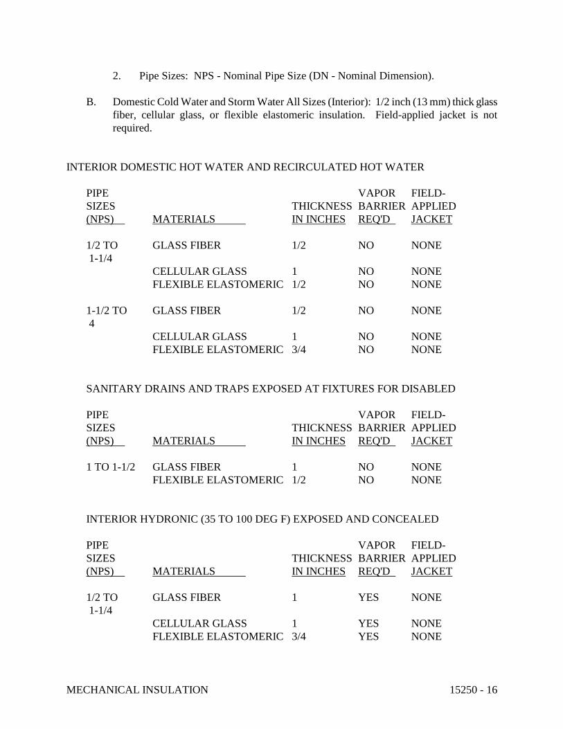
MECHANICAL INSULATION 15250 - 16
2. Pipe Sizes: NPS - Nominal Pipe Size (DN - Nominal Dimension).
B. Domestic Cold Water and Storm Water All Sizes (Interior): 1/2 inch (13 mm) thick glass
fiber, cellular glass, or flexible elastomeric insulation. Field-applied jacket is not
required.
INTERIOR DOMESTIC HOT WATER AND RECIRCULATED HOT WATER
PIPE VAPOR FIELD-
SIZES THICKNESS BARRIER APPLIED
(NPS) MATERIALS IN INCHES REQ'D JACKET
1/2 TO GLASS FIBER 1/2 NO NONE
1-1/4
CELLULAR GLASS 1 NO NONE
FLEXIBLE ELASTOMERIC 1/2 NO NONE
1-1/2 TO GLASS FIBER 1/2 NO NONE
4
CELLULAR GLASS 1 NO NONE
FLEXIBLE ELASTOMERIC 3/4 NO NONE
SANITARY DRAINS AND TRAPS EXPOSED AT FIXTURES FOR DISABLED
PIPE VAPOR FIELD-
SIZES THICKNESS BARRIER APPLIED
(NPS) MATERIALS IN INCHES REQ'D JACKET
1 TO 1-1/2 GLASS FIBER 1 NO NONE
FLEXIBLE ELASTOMERIC 1/2 NO NONE
INTERIOR HYDRONIC (35 TO 100 DEG F) EXPOSED AND CONCEALED
PIPE VAPOR FIELD-
SIZES THICKNESS BARRIER APPLIED
(NPS) MATERIALS IN INCHES REQ'D JACKET
1/2 TO GLASS FIBER 1 YES NONE
1-1/4
CELLULAR GLASS 1 YES NONE
FLEXIBLE ELASTOMERIC 3/4 YES NONE

MECHANICAL INSULATION 15250 - 17
1-1/2 TO GLASS FIBER 1 YES NONE
4
CELLULAR GLASS 1-1/2 YES NONE
FLEXIBLE ELASTOMERIC 3/4 YES NONE
EXTERIOR HYDRONIC (35 TO 100 DEG F) EXPOSED AND CONCEALED
PIPE VAPOR FIELD-
SIZES THICKNESS BARRIER APPLIED
(NPS) MATERIALS IN INCHES REQ'D JACKET
1/2 TO GLASS FIBER 2 YES (P)(A)(SS)
1-1/4
CELLULAR GLASS 2 YES (P)(A)(SS)
FLEXIBLE ELASTOMERIC 3/4 YES NONE
1-1/2 TO GLASS FIBER 2 YES (P)(A)(SS)
4
CELLULAR GLASS 2-1/2 YES (P)(A)(SS)
FLEXIBLE ELASTOMERIC 3/4 YES NONE
3.17 EQUIPMENT INSULATION SCHEDULES
INTERIOR EXPOSED DOMESTIC COLD WATER EQUIPMENT, TANKS, AND PUMPS
VAPOR FIELD-
THICKNESS IN BARRIER APPLIED
MATERIAL FORM INCHES REQ'D JACKET
GLASS FIBER BLOCK OR 1 YES (P)(K)(A)(SS)
BOARD
CELLULAR GLASS BLOCK 1-1/2 YES (P)(K)(A)(SS)
FLEXIBLE SHEET 3/4 YES NONE
ELASTOMERIC
INTERIOR EXPOSED DOMESTIC HOT WATER EQUIPMENT, TANKS, AND PUMPS
VAPOR FIELD-
THICKNESS IN BARRIER APPLIED
MATERIAL FORM INCHES REQ'D JACKET
GLASS FIBER BLOCK 2 NO (A)(SS)
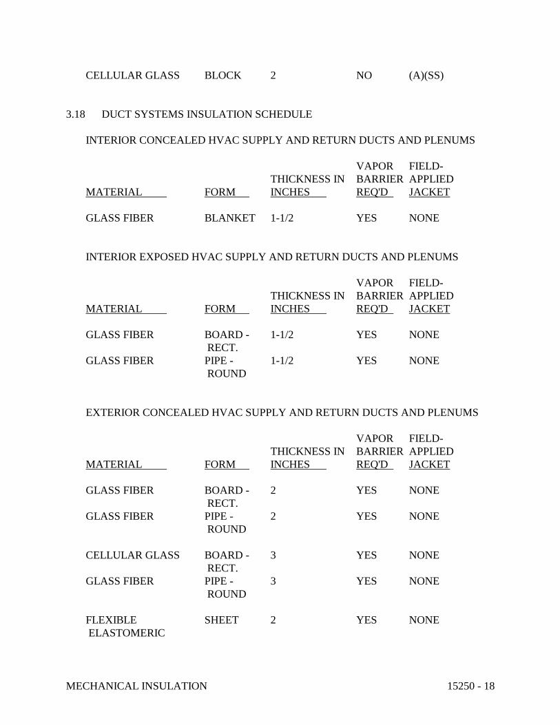
MECHANICAL INSULATION 15250 - 18
CELLULAR GLASS BLOCK 2 NO (A)(SS)
3.18 DUCT SYSTEMS INSULATION SCHEDULE
INTERIOR CONCEALED HVAC SUPPLY AND RETURN DUCTS AND PLENUMS
VAPOR FIELD-
THICKNESS IN BARRIER APPLIED
MATERIAL FORM INCHES REQ'D JACKET
GLASS FIBER BLANKET 1-1/2 YES NONE
INTERIOR EXPOSED HVAC SUPPLY AND RETURN DUCTS AND PLENUMS
VAPOR FIELD-
THICKNESS IN BARRIER APPLIED
MATERIAL FORM INCHES REQ'D JACKET
GLASS FIBER BOARD - 1-1/2 YES NONE
RECT.
GLASS FIBER PIPE - 1-1/2 YES NONE
ROUND
EXTERIOR CONCEALED HVAC SUPPLY AND RETURN DUCTS AND PLENUMS
VAPOR FIELD-
THICKNESS IN BARRIER APPLIED
MATERIAL FORM INCHES REQ'D JACKET
GLASS FIBER BOARD - 2 YES NONE
RECT.
GLASS FIBER PIPE - 2 YES NONE
ROUND
CELLULAR GLASS BOARD - 3 YES NONE
RECT.
GLASS FIBER PIPE - 3 YES NONE
ROUND
FLEXIBLE SHEET 2 YES NONE
ELASTOMERIC

MECHANICAL INSULATION 15250 - 19
INTERIOR EXPOSED HVAC SUPPLY FANS, AIR HANDLING UNITS, CASINGS, AND
PLENUMS
VAPOR FIELD-
THICKNESS IN BARRIER APPLIED
MATERIAL FORM INCHES REQ'D JACKET
GLASS FIBER BOARD 2 YES NONE
END OF SECTION 15250

PLUMBING PIPING 15410 - 1
SECTION 15410 - PLUMBING PIPING
PART 1 - GENERAL
1.1 RELATED DOCUMENTS
A. Drawings and general provisions of the Contract, including General and Supplementary
Conditions and Division 1 Specification Sections, apply to this Section.
1.2 SUMMARY
A. This Section includes plumbing piping systems to a point 60 inches (1500 mm) outside
the building. Systems include the following:
1. Potable water distribution, including cold- and hot-water supply and hot-water
circulation.
2. Drainage and vent systems, including sanitary.
B. Related Sections: The following sections contain requirements that relate to this Section:
1. Division 15 Section "Basic Mechanical Materials and Methods" for piping joining
materials, joint construction, and installation requirements not specified in this
Section.
2. Division 15 Section "Meters and Gages" for thermometers, pressure gages, and
fittings.
3. Division 15 Section "Plumbing Specialties" for plumbing system components.
1.3 SYSTEM PERFORMANCE REQUIREMENTS
A. Provide components and installation capable of producing piping systems with the
following minimum working pressure ratings, except where indicated otherwise:
1. Water Distribution Systems, Below Ground: 150 psig (1035 kPa).
2. Water Distribution Systems, Above Ground: 125 psig (860 kPa).
3. Soil, Waste, and Vent Systems: 10-foot head of water (30 kPa).
1.4 SUBMITTALS
A. General: Submit the following in accordance with Conditions of Contract and Division 1
Specification Sections.
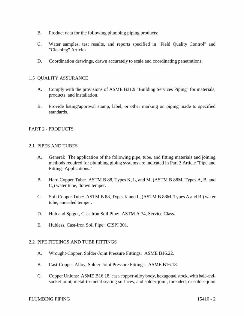
PLUMBING PIPING 15410 - 2
B. Product data for the following plumbing piping products:
C. Water samples, test results, and reports specified in "Field Quality Control" and
"Cleaning" Articles.
D. Coordination drawings, drawn accurately to scale and coordinating penetrations.
1.5 QUALITY ASSURANCE
A. Comply with the provisions of ASME B31.9 "Building Services Piping" for materials,
products, and installation.
B. Provide listing/approval stamp, label, or other marking on piping made to specified
standards.
PART 2 - PRODUCTS
2.1 PIPES AND TUBES
A. General: The application of the following pipe, tube, and fitting materials and joining
methods required for plumbing piping systems are indicated in Part 3 Article "Pipe and
Fittings Applications."
B. Hard Copper Tube: ASTM B 88, Types K, L, and M, (ASTM B 88M, Types A, B, and
C,) water tube, drawn temper.
C. Soft Copper Tube: ASTM B 88, Types K and L, (ASTM B 88M, Types A and B,) water
tube, annealed temper.
D. Hub and Spigot, Cast-Iron Soil Pipe: ASTM A 74, Service Class.
E. Hubless, Cast-Iron Soil Pipe: CISPI 301.
2.2 PIPE FITTINGS AND TUBE FITTINGS
A. Wrought-Copper, Solder-Joint Pressure Fittings: ASME B16.22.
B. Cast-Copper-Alloy, Solder-Joint Pressure Fittings: ASME B16.18.
C. Copper Unions: ASME B16.18, cast-copper-alloy body, hexagonal stock, with ball-and-
socket joint, metal-to-metal seating surfaces, and solder-joint, threaded, or solder-joint

PLUMBING PIPING 15410 - 3
and threaded ends.
1. Threaded Ends: Threads conforming to ASME B1.20.1.
D. Hub and Spigot, Cast-Iron Soil Pipe Fittings: ASTM A 74, Service Class.
E. Hubless, Cast-Iron Soil Pipe Fittings: CISPI 301.
F. Cast-Iron, Sovent Drainage Fittings: ASME B16.45.
2.3 JOINING MATERIALS
A. Solder, brazing, and welding filler metals are specified in Division 15 Section "Basic
Mechanical Materials and Methods."
B. Cast-Iron Soil Pipe and Fittings: ASTM C 564 neoprene rubber gaskets and lubricant.
C. Ductile-Iron Pipe and Ductile-Iron or Cast-Iron Fittings: The following materials apply:
1. Push-On Joints: AWWA C111 rubber gaskets and lubricant.
2. Mechanical Joints: AWWA C111 ductile-iron or gray-iron glands, high-strength
steel bolts and nuts, and rubber gaskets.
3. Flanged Joints: AWWA C115 ductile-iron or gray-iron pipe flanges, rubber
gaskets, and high-strength steel bolts and nuts.
D. Stainless Steel, Heavy-Duty Couplings for Hubless Cast-Iron Soil Pipe and Fittings:
ASTM C 564 neoprene sealing gasket, with Type 304 stainless-steel housing or shield and
stainless-steel clamps. Coupling shall be 3 inches (75 mm) wide in sizes 1-1/2 to 4 inches
(DN 40 to DN 100) and 4 inches (100 mm) wide in sizes 5 to 10 inches (DN 125 to DN
250).
E. Sleeve-Type Couplings for Plain-End, Nonpressure System Pipe: Rubber or elastomeric
sleeve and stainless steel band assembly, fabricated to match outside diameters of pipes to
be joined.
1. Sleeves: ASTM C 564, rubber for cast-iron soil pipe and ASTM F 477, elastomeric
seal for plastic pipe. Sleeves for dissimilar or other pipe materials shall be
compatible with pipe materials being joined.
2. Bands: Stainless steel, one at each pipe insert.
2.4 VALVES
A. Refer to Division 15 Section "Valves" for gate, globe, ball, butterfly, and check valves.
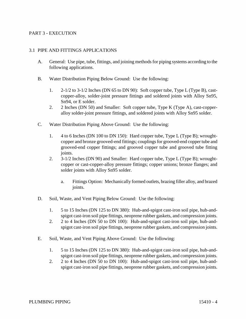
PLUMBING PIPING 15410 - 4
PART 3 - EXECUTION
3.1 PIPE AND FITTINGS APPLICATIONS
A. General: Use pipe, tube, fittings, and joining methods for piping systems according to the
following applications.
B. Water Distribution Piping Below Ground: Use the following:
1. 2-1/2 to 3-1/2 Inches (DN 65 to DN 90): Soft copper tube, Type L (Type B), cast-
copper-alloy, solder-joint pressure fittings and soldered joints with Alloy Sn95,
Sn94, or E solder.
2. 2 Inches (DN 50) and Smaller: Soft copper tube, Type K (Type A), cast-copper-
alloy solder-joint pressure fittings, and soldered joints with Alloy Sn95 solder.
C. Water Distribution Piping Above Ground: Use the following:
1. 4 to 6 Inches (DN 100 to DN 150): Hard copper tube, Type L (Type B); wrought-
copper and bronze grooved-end fittings; couplings for grooved-end copper tube and
grooved-end copper fittings; and grooved copper tube and grooved tube fitting
joints.
2. 3-1/2 Inches (DN 90) and Smaller: Hard copper tube, Type L (Type B); wrought-
copper or cast-copper-alloy pressure fittings; copper unions; bronze flanges; and
solder joints with Alloy Sn95 solder.
a. Fittings Option: Mechanically formed outlets, brazing filler alloy, and brazed
joints.
D. Soil, Waste, and Vent Piping Below Ground: Use the following:
1. 5 to 15 Inches (DN 125 to DN 380): Hub-and-spigot cast-iron soil pipe, hub-and-
spigot cast-iron soil pipe fittings, neoprene rubber gaskets, and compression joints.
2. 2 to 4 Inches (DN 50 to DN 100): Hub-and-spigot cast-iron soil pipe, hub-and-
spigot cast-iron soil pipe fittings, neoprene rubber gaskets, and compression joints.
E. Soil, Waste, and Vent Piping Above Ground: Use the following:
1. 5 to 15 Inches (DN 125 to DN 380): Hub-and-spigot cast-iron soil pipe, hub-and-
spigot cast-iron soil pipe fittings, neoprene rubber gaskets, and compression joints.
2. 2 to 4 Inches (DN 50 to DN 100): Hub-and-spigot cast-iron soil pipe, hub-and-
spigot cast-iron soil pipe fittings, neoprene rubber gaskets, and compression joints.
PLUMBING PIPING 15410 - 5
3.2 VALVE APPLICATIONS
A. Drawings indicate valve types to be used. Where specific valve types are not indicated,
the following requirements apply:
1. Shutoff Duty: Use gate, ball, or butterfly valves.
2. Throttling Duty: Use globe, ball, or butterfly valves.
3.3 PIPING INSTALLATION, GENERAL
A. Basic piping installation requirements are specified in Division 15 Section "Basic
Mechanical Materials and Methods."
3.4 SERVICE ENTRANCE PIPING
A. Extend water distribution piping and connect to water service piping of size and in
location indicated for service entrance to building.
B. Install shutoff valve, hose-end drain valve, strainer, pressure gage, and test tee with valve,
inside building at water service entrance.
C. Ductile-Iron Water Service Pipe: Comply with AWWA C600. Install buried pipe inside
building between shutoff valve, wall and floor penetrations, and point 60 inches (1500
mm) outside building, with restrained joints, including anchoring pipe to wall or floor.
Provide supports (thrust blocks) at vertical and horizontal offsets.
1. Wrap pipe with polyethylene encasement.
D. Extend building sanitary drain piping and connect to sanitary sewer piping of size and in
location indicated for service entrance to building. Install cleanout and extension to grade
at connection of building sanitary drain and building sanitary sewer. Sanitary sewerage
piping is specified in separate Section of Division 2.
E. Install sleeve and mechanical sleeve seal at service penetrations through foundation wall
for watertight installation.
3.5 WATER DISTRIBUTION PIPING INSTALLATION
A. Install piping with 1/32-inch-per-foot (1:400) (1/4 percent) slope downward toward drain.
B. Install piping level without pitch.

PLUMBING PIPING 15410 - 6
C. Fittings Option: Mechanically formed outlets may be used instead of fittings.
3.6 DRAINAGE AND VENT PIPING INSTALLATION
A. Install cast-iron soil pipe and cast-iron soil pipe fittings according to CISPI 1990 revised
and edited edition of "Cast Iron Soil Pipe and Fittings Handbook, Volume I," Chapter IV,
"Installation of Cast Iron Soil Pipe and Fittings."
B. Make changes in direction for drainage and vent piping using appropriate Y branches, Y
branches with 1/8 bends, and long-sweep 1/4, 1/5, 1/6, 1/8, and 1/16 bends. Sanitary tees
and short-sweep quarter bends may be used on vertical stacks of drainage lines where
change in direction of flow is from horizontal to vertical. Use long-turn double-Y-branch
and 1/8-bend fittings where 2 fixtures are installed back to back or side by side and have a
common drain. Straight tees, elbows, and crosses may be used on vent lines. Make no
change in direction of flow greater than 90 degrees. Where different sizes of drainage
pipes and fittings are connected, use proper size standard increasers and reducers.
Reduction of the size of drainage piping in the direction of flow is prohibited.
C. Lay buried building drains beginning at low point of each system, true to grades and
alignment indicated, with unbroken continuity of invert. Place hub or bell ends of piping
facing upstream. Install required gaskets according to manufacturer's recommendations
for use of lubricants, cements, and other special installation requirements. Maintain swab
or drag in piping and pull past each joint as completed.
D. Install drainage and vent piping at the following minimum slopes, except where another
slope is indicated:
1. Sanitary Building Drain: 1/4 inch per foot (1:50) (2 percent) for piping 3 inches
(DN 80) and smaller; 1/8 inch per foot (1:100) (1 percent) for piping 4 inches (DN
100) and larger.
2. Horizontal Sanitary Drainage Piping: 1/4 inch per foot (1:50) (2 percent).
3. Vent Piping: 1/8 inch per foot (1:100) (1 percent).
E. Install engineered sanitary drainage and vent systems in locations indicated and as
follows:
1. Combination Waste and Vent Systems: Comply with standards of authority having
jurisdiction.
2. Reduced-Size Venting Systems: Comply with design.
F. Sleeves are not required for cast-iron soil pipes passing through concrete slab, without
membrane waterproofing, on grade.

PLUMBING PIPING 15410 - 7
3.7 JOINT CONSTRUCTION
A. Cast-Iron Soil Pipe and Cast-Iron Soil Pipe Fitting Joints: Make joints according to
recommendations in CISPI 1990 revised and edited edition of "Cast Iron Soil Pipe and
Fittings Handbook, Volume I," Chapter IV, "Installation of Cast Iron Soil Pipe and
Fittings."
1. Compression Joint: Make with neoprene gasket matching class of pipe and fittings.
2. Hubless Joint: Make with neoprene gasket and sleeve or clamp.
3.8 INSTALLATION OF VALVES
A. Sectional Valves: Install sectional valves close to main on each branch and riser serving 2
or more plumbing fixtures or equipment connections and where indicated. Use gate or
ball valves for sectional valves 2 inches (DN 50) and smaller. Use gate or butterfly valves
for sectional valves 2-1/2 inches (DN 65) and larger.
B. Shutoff Valves: Install shutoff valves on inlet to each plumbing equipment item, on each
supply to each plumbing fixture not having stops on supplies, and elsewhere as indicated.
For shutoff valves 2 inches (DN 50) and smaller, use gate or ball valves; for shutoff
valves 2-1/2 inches (DN 65) and larger, use gate or butterfly valves.
C. Drain Valves: Install drain valves on each plumbing equipment item located to drain
equipment for service and repair. Install drain valve at base of each riser, at low points of
horizontal runs, and where required to drain water distribution piping system.
1. Install hose-end drain valves at low points in water mains, risers, and branches.
2. Install stop and waste drain valves where indicated.
D. Check Valves: Install swing check valve on discharge side of each pump and elsewhere as
indicated. Use MSS SP-80, Class 125, cast-bronze body for 2 inches (DN 50) and smaller
piping and MSS SP-71, Class 125, cast-iron body for 2-1/2 inches (DN 65) and larger
piping.
E. Balance Valves: Install valve in each hot-water circulating loop, discharge side of each
pump, and elsewhere as indicated. Use ball valve for 2 inches (DN 50) and smaller piping
and butterfly valve for 2-1/2 inches (DN 65) and larger piping.
3.9 HANGERS AND SUPPORTS INSTALLATION
A. Hanger and support devices are specified in Division 15 Section "Hangers and Supports."
B. Install hangers for horizontal piping with following maximum spacing and min. rod sizes:
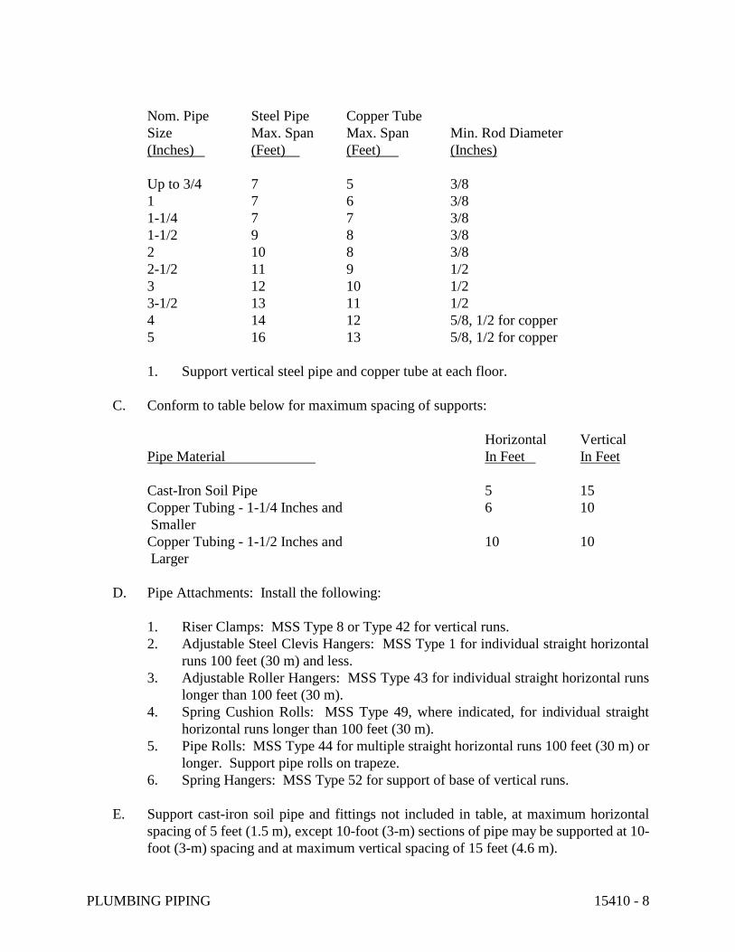
PLUMBING PIPING 15410 - 8
Nom. Pipe Steel Pipe Copper Tube
Size Max. Span Max. Span Min. Rod Diameter
(Inches) (Feet) (Feet) (Inches)
Up to 3/4 7 5 3/8
1 7 6 3/8
1-1/4 7 7 3/8
1-1/2 9 8 3/8
2 10 8 3/8
2-1/2 11 9 1/2
3 12 10 1/2
3-1/2 13 11 1/2
4 14 12 5/8, 1/2 for copper
5 16 13 5/8, 1/2 for copper
1. Support vertical steel pipe and copper tube at each floor.
C. Conform to table below for maximum spacing of supports:
Horizontal Vertical
Pipe Material In Feet In Feet
Cast-Iron Soil Pipe 5 15
Copper Tubing - 1-1/4 Inches and 6 10
Smaller
Copper Tubing - 1-1/2 Inches and 10 10
Larger
D. Pipe Attachments: Install the following:
1. Riser Clamps: MSS Type 8 or Type 42 for vertical runs.
2. Adjustable Steel Clevis Hangers: MSS Type 1 for individual straight horizontal
runs 100 feet (30 m) and less.
3. Adjustable Roller Hangers: MSS Type 43 for individual straight horizontal runs
longer than 100 feet (30 m).
4. Spring Cushion Rolls: MSS Type 49, where indicated, for individual straight
horizontal runs longer than 100 feet (30 m).
5. Pipe Rolls: MSS Type 44 for multiple straight horizontal runs 100 feet (30 m) or
longer. Support pipe rolls on trapeze.
6. Spring Hangers: MSS Type 52 for support of base of vertical runs.
E. Support cast-iron soil pipe and fittings not included in table, at maximum horizontal
spacing of 5 feet (1.5 m), except 10-foot (3-m) sections of pipe may be supported at 10-
foot (3-m) spacing and at maximum vertical spacing of 15 feet (4.6 m).
PLUMBING PIPING 15410 - 9
F. Support plastic pipe and tubing not included in table according to manufacturer's
recommendations.
3.10 CONNECTIONS
A. Supply Runouts to Fixtures: Install hot- and cold-water supply piping runouts of sizes
indicated, but not smaller than required by plumbing code to fixtures.
B. Drainage Runouts to Fixtures: Provide drainage and vent piping runouts, with approved
trap, of sizes indicated, but not smaller than required by plumbing code, to plumbing
fixtures and drains.
C. Locate drainage piping runouts as close as possible to bottom of floor slab supporting
fixtures or drains.
D. Mechanical Equipment Connections: Connect hot- and cold-water supply piping system
to mechanical equipment as indicated. Provide shutoff valve and union for each
connection; provide drain valve on drain connection. Use flanges instead of unions for
connections 2-1/2 inches (DN 65) and larger.
3.11 FIELD QUALITY CONTROL
A. Inspect water distribution piping as follows:
1. Do not enclose, cover, or put into operation water distribution piping system until it
has been inspected and approved by the authority having jurisdiction.
2. During progress of the installation, notify the plumbing official having jurisdiction
at least 24 hours prior to time inspection must be made. Perform tests specified
below in presence of the plumbing official.
a. Roughing-In Inspection: Arrange for inspection of piping system before
concealed or closed-in after system roughing-in and prior to setting fixtures.
b. Final Inspection: Arrange for final inspection by plumbing official to observe
tests specified below and to ensure compliance with requirements of
plumbing code.
3. Reinspections: When a plumbing official finds that piping system will not pass test
or inspection, make required corrections and arrange for reinspection by the
plumbing official.
4. Reports: Prepare inspection reports signed by plumbing official.
B. Test water distribution piping as follows:
PLUMBING PIPING 15410 - 10
1. Test for leaks and defects in new water distribution piping systems and parts of
existing systems that have been altered, extended, or repaired. If testing is
performed in segments, submit separate report for each test, complete with diagram
of portion of system tested.
2. Leave uncovered and unconcealed in new, altered, extended, or replaced water
distribution piping until it has been tested and approved. Expose work that has
been covered or concealed before it has been tested and approved for testing.
3. Cap and subject the piping system to a static water pressure of 50 psig (345 kPa)
above the operating pressure without exceeding pressure rating of piping system
materials. Isolate test source and allow to stand for 4 hours. Leaks and loss in test
pressure constitute defects that must be repaired.
4. Repair leaks and defects with new materials and retest system or portion thereof
until satisfactory results are obtained.
5. Prepare reports for tests and required corrective action.
C. Inspect drainage piping as follows:
1. Do not enclose, cover, or put into operation drainage and vent piping system until it
has been inspected and approved by the authority having jurisdiction.
2. During progress of installation, notify the plumbing official having jurisdiction at
least 24 hours prior to time such inspection must be made. Perform tests specified
below in presence of the plumbing official.
a. Roughing-In Inspection: Arrange for inspection of piping system after
system roughing-in, before concealing, and prior to setting fixtures.
b. Final Inspection: Arrange for final inspection by plumbing official to observe
tests specified below and to ensure compliance with requirements of
plumbing code.
3. Reinspections: Make required corrections and arrange for reinspection by plumbing
official when piping system fails to pass test or inspection.
4. Reports: Prepare inspection reports signed by the plumbing official.
D. Drainage and Vent Piping System Tests: Test drainage and vent systems according to
procedures of authority having jurisdiction or, in absence of published procedure, as
follows:
1. Test for leaks and defects in new drainage and vent piping systems and parts of
existing systems that have been altered, extended, or repaired. If testing is
performed in segments, submit a separate report for each test, complete with a
diagram of the portion of the system tested.
2. Leave uncovered and unconcealed in new, altered, extended, or replaced drainage
and vent piping until it has been tested and approved. Expose for testing work that
has been covered or concealed before it has been tested and approved.
3. Rough Plumbing Test Procedure: Except for outside leaders and perforated or
PLUMBING PIPING 15410 - 11
open-jointed drain tile, test piping of plumbing drainage and venting systems on
completion of roughing-in piping installation. Tightly close all openings in piping
system and fill with water to point of overflow, but not less than 10 feet head of
water (30 kPa). Water level shall not drop during the period from 15 minutes
before inspection starts through completion of inspection. Inspect joints for leaks.
4. Finished Plumbing Test Procedure: After plumbing fixtures have been set and their
traps filled with water, test connections and prove gastight and watertight. Plug
stack openings on roof and building drain where it leaves the building and introduce
air into the system equal to pressure of 1 inch water column (250 Pa). Use a U tube
or manometer inserted in the trap of a water closet to measure this pressure. Air
pressure shall remain constant without introducing additional air throughout period
of inspection. Inspect plumbing fixture connections for gas and water leaks.
5. Repair leaks and defects using new materials and retest system or portion thereof
until satisfactory results are obtained.
6. Prepare reports for tests and required corrective action.
3.12 CLEANING
A. Clean and disinfect water distribution piping as follows:
1. Purge new potable water distribution piping systems and parts of existing potable
water systems that have been altered, extended, or repaired prior to use.
2. Use purging and disinfecting procedure prescribed by authority having jurisdiction
or, if a method is not prescribed by that authority, the procedure described in either
AWWA C651 or AWWA C652 or as described below:
a. Flush piping system with clean, potable water until dirty water does not
appear at outlets.
b. Fill system or part thereof with water/chlorine solution containing at least 50
parts per million of chlorine. Isolate (valve off) and allow to stand for 24
hours.
c. Drain system or part thereof of previous solution and refill with
water/chlorine solution containing at least 200 parts per million of chlorine.
Isolate and allow to stand for 3 hours.
d. Flush system with clean, potable water until chlorine does not remain in
water coming from system following allowed standing time.
e. Submit water samples in sterile bottles to authority having jurisdiction.
Repeat procedure if biological examination made by the authority shows
evidence of contamination.
B. Prepare and submit reports for purging and disinfecting activities.
C. Clean interior of piping system. Remove dirt and debris as work progresses.

PLUMBING PIPING 15410 - 12
3.13 COMMISSIONING
A. Fill water systems. Check compression tanks to determine that they are not air bound and
that system is completely full of water.
B. Before operating systems, perform these steps:
1. Close drain valves, hydrants, and hose bibbs.
2. Open shutoff valves to full open position.
3. Open throttling valves to proper setting.
4. Remove plugs used during testing of piping systems and plugs used for temporary
sealing of piping during installation.
5. Remove and clean strainer screens. Close drain valves and replace drain plugs.
6. Remove filter cartridges from housings and verify that cartridges are as specified
for application where used, clean, and ready for use.
C. Check plumbing equipment and verify proper settings, adjustments, and operation. Do
not operate water heaters before filling with water.
D. Check plumbing specialties and verify proper settings, adjustments, and operation.
E. Energize pumps and verify proper operation.
3.14 PROTECTION
A. Protect drains during remainder of construction period to avoid clogging with dirt and
debris and to prevent damage from traffic and construction work.
B. Place plugs in ends of uncompleted piping at end of day or when work stops.
END OF SECTION 15410

REFRIGERANT PIPING 15530 - 1
SECTION 15530 - REFRIGERANT PIPING
PART 1 - GENERAL
1.1 RELATED DOCUMENTS
A. Drawings and general provisions of the Contract, including General and Supplementary
Conditions and Division 1 Specification Sections, apply to this Section.
1.2 SUMMARY
A. This Section includes refrigerant piping used for air-conditioning applications, including
pipes, tubing, fittings, and specialties; special-duty valves; and refrigerants.
B. Related Sections: The following Sections contain requirements that relate to this Section:
1. Section "Roof Accessories" for roof curbs, piping supports, and roof penetration
boots.
2. Section "Joint Sealants" for materials and methods for sealing pipe penetrations
through basement walls and fire/smoke barriers.
3. Division 15 Section "Mechanical Insulation" for pipe insulation.
1.3 SUBMITTALS
A. General: Submit each item in this Article according to the Conditions of the Contract and
Division 1 Specification Sections.
B. Product Data for each valve type and refrigerant piping specialty specified.
C. Shop Drawings showing layout of refrigerant piping, specialties, and fittings, including
pipe and tube sizes, flow capacities, valve arrangements and locations, slopes of horizontal
runs, wall and floor penetrations, and equipment connection details. Show interface and
spatial relationship between piping and equipment.
1. Refrigerant piping indicated is schematic only. Size and design the layout and
installation of the piping, including oil traps, double risers, specialties, and pipe and
tube sizes, to ensure proper operation and conformance with warranties of connected
equipment.
D. Qualification data for firms and persons specified in the "Quality Assurance" Article to
demonstrate their capabilities and experience.
E. Maintenance data for refrigerant valves and piping specialties to include in the operation
and maintenance manual specified in Division 1 Sections and Division 15 Section "Basic

REFRIGERANT PIPING 15530 - 2
Mechanical Requirements."
1.4 QUALITY ASSURANCE
A. ASME Compliance: Qualify brazing and welding processes and operators according to
ASME Boiler and Pressure Vessel Code, Section IX, "Welding and Brazing
Qualifications."
B. Regulatory Requirements: Comply with provisions of the following codes:
1. ASME B31.5, "Refrigeration Piping."
2. ASHRAE 15, "Safety Code for Mechanical Refrigeration."
C. UL Standard: Provide products complying with UL 207, "Refrigerant-Containing
Components and Accessories, Nonelectrical"; or UL 429, "Electrically Operated Valves."
D. Listing and Labeling: Provide products specified in this Section that are UL listed and
labeled.
1.5 SEQUENCING AND SCHEDULING
A. Coordinate the installation of roof curbs, equipment supports, and roof penetrations. Roof
specialties are specified in Division 7 Sections.
1.6 EXTRA MATERIALS
A. Furnish extra materials described below that match products installed, are packaged with
protective covering for storage, and are identified with labels describing contents.
1. Refrigeration Oil Test Kits: 2 each, containing everything required to conduct 1 test.
2. Refrigerant: 2 containers each, with 20 lb (9 kg) of refrigerant.
3. Filter-Dryer Cartridges: 3 of each type.
PART 2 - PRODUCTS
2.1 MANUFACTURERS
A. Available Manufacturers: Subject to compliance with requirements, manufacturers
offering products that may be incorporated into the Work include, but are not limited to, the
following:
B. Manufacturers: Subject to compliance with requirements, provide products by one of the
following:
REFRIGERANT PIPING 15530 - 3
1. Refrigerants:
a. Allied Signal Inc.; Genetron Refrigerants.
b. DuPont Company; Fluorochemicals Div.
c. Elf Atochem North America, Inc.
d. ICI Americas Inc.; Fluorochemicals Bus.
2. Refrigerant Valves and Specialties:
a. Danfoss Electronics, Inc.
b. Eaton Corporation; Industrial Control Div.
c. Emerson Electric Company; Alco Controls Div.
d. Henry Valve Company.
e. Parker-Hannifin Corp.; Refrigeration & Air Conditioning Division.
f. Sporlan Valve Company.
2.2 PIPES AND TUBES
A. Hard Copper Tube: ASTM B 280, Type ACR, drawn temper.
B. Hard Copper Tube: ASTM B 88, Type L (ASTM B 88M, Type B), drawn temper.
C. Soft Copper Tube: ASTM B 280, Type ACR, annealed temper.
D. Soft Copper Tube: ASTM B 88, Type L (ASTM B 88M, Type B), annealed temper.
E. Soft Copper Tube: ASTM B 88, Type K (ASTM B 88M, Type A), annealed temper.
F. Steel Pipe: ASTM A 53, Schedule 40, seamless, black steel.
2.3 PIPE AND TUBE FITTINGS
A. Copper Fittings: ASME B16.22, wrought-copper streamlined pattern.
B. Steel Fittings: ASTM A 234 (ASTM A 234M), seamless or welded, for welded joints.
C. Steel Flanges and Flanged Fittings: ASME B16.5, steel; including bolts, nuts, and
gaskets, butt-welded end connection, and raised face.
2.4 JOINING MATERIALS
A. Brazing Filler Metals: AWS A5.8, Classification BAg-1 (Silver).
B. Steel Flange Gasket Material: Thickness and material suitable for refrigerant, and design
temperatures and pressures.
REFRIGERANT PIPING 15530 - 4
C. Welding Materials: Comply with ASME Boiler and Pressure Vessel Code Section II,
Part C, for welding materials appropriate for pipe being welded.
2.5 VALVES
A. Diaphragm Packless Valves: 500-psig (3450-kPa) working pressure and 275 deg F (135
deg C) working temperature, globe or angle pattern, forged-brass or bronze body and
bonnet, phosphor bronze and stainless-steel diaphragms, rising stem and handwheel,
stainless-steel spring, nylon seat disc, with solder-end connections.
B. Packed-Angle Valves: 500-psig (3450-kPa) working pressure and 275 deg F (135 deg C)
working temperature, forged-brass or bronze body, forged-brass seal caps with copper
gasket, back seating, rising stem and seat, molded stem packing, with solder-end
connections.
C. Check Valves--Smaller than 1-Inch NPS (DN25): 500-psig (3450-kPa) operating
pressure, 300 deg F (149 deg C) operating temperature; cast-brass body, with removable
piston, PTFE seat, and stainless-steel spring; straight-through globe design. Valve shall
be straight-through pattern, with solder-end connections.
D. Check Valves--Larger than 1-Inch NPS (DN25): 450-psig (3100-kPa) operating pressure,
300 deg F (149 deg C) operating temperature; cast-bronze body, with cast-bronze or
forged-brass bolted bonnet; floating piston with mechanically retained PTFE seat disc.
Valve shall be straight-through or angle pattern, with solder-end connections.
E. Service Valves: 500-psig (3450-kPa) pressure rating, forged-brass body with copper
stubs, brass caps, removable valve core, integral ball check valve, with solder-end
connections.
F. Solenoid Valves: Conform to ARI 760; 250 deg F (121 deg C) temperature rating,
400-psig (2760-kPa) working pressure; forged brass, with PTFE valve seat, 2-way
straight-through pattern, and solder-end connections; manual operator; with NEMA 250,
Type 1 solenoid enclosure with 1/2-inch (13-mm) conduit adapter, and 24-V normally
closed holding coil.
G. Pressure-Regulating Valves: Conform to ARI 770; pilot operated, forged brass or cast
bronze with pilot operator, stainless-steel bottom spring, pressure-gage tappings, 24-V dc
standard coil, and wrought-copper fittings for solder-end connections.
H. Pressure-Regulating Valves: Conform to ARI 770; direct acting, brass with pilot
operator, stainless-steel diaphragm, standard coil, and solder-end connections.
I. Pressure Relief Valves: Straight or angle brass body and disc, neoprene seat, factory
sealed and ASME labeled, for standard pressure setting.
J. Thermal Expansion Valves: Conform to ARI 750; thermostatic-adjustable, modulating
type; size as required and factory set for superheat requirements; solder-end connections;
with sensing bulb, distributor having side connection for hot-gas bypass line, and external
REFRIGERANT PIPING 15530 - 5
equalizer line.
K. Hot-Gas Bypass Valve: Adjustable, sized for capacity equal to last step of compressor
unloading; solder-end connections.
2.6 REFRIGERANT PIPING SPECIALTIES
A. Straight- or Angle-Type Strainers: 430-psig (2960-kPa) working pressure; forged-brass
or steel body with stainless-steel wire or brass-reinforced Monel screen, and screwed
cleanout plug, with solder-end connections.
B. Straight, Non-Cleanable-Type Strainers: 500-psig (3450-kPa) working pressure; steel
shell with stainless-steel screen, with solder-end connections.
C. Moisture/Liquid Indicators: 500-psig (3450-kPa) operating pressure, 200 deg F (93
deg C) operating temperature; forged-brass body, with replaceable, polished, optical
viewing window with color-coded moisture indicator, and solder-end connections.
D. Replaceable-Core Filter-Dryers: 500-psig (3450-kPa) operating pressure; steel shell,
flange ring, and spring, ductile-iron cover plate with steel cap screws, and wrought-copper
fittings for solder-end connections; with replaceable-core kit, including gaskets, as follows:
1. Filter Cartridge: Pleated media with integral end rings, stainless-steel support,
ARI 730 rated for capacity.
2. Filter-Dryer Cartridge: Pleated media with solid-core sieve with activated alumina,
ARI 730 rated for capacity.
3. Wax Removal Cartridge: Molded, bonded core of activated charcoal and desiccant
with integral gaskets.
E. Permanent Filter-Dryer: 350-psig (2140-kPa) maximum operating pressure, 225 deg F
(107 deg C) maximum operating temperature; steel shell, and wrought-copper fittings for
solder-end connections; molded-felt core surrounded by desiccant.
F. Flanged Unions: 400-psig (2760-kPa) working pressure, 330 deg F (165 deg C)
maximum operating temperature; 2 brass tailpiece adapters for solder-end connections to
copper tubing; forged-steel flanges for 1- to 1-1/2-inch (22- to 41-mm) nominal
copper-tube size and ductile iron for 2- to 3-inch (54- to 79-mm) nominal copper-tube size
with 4 plated steel bolts, with silicon bronze nuts and fiber gasket; factory-applied
rust-resistant coating on flanges and bolts.
G. Flexible Connectors: 500-psig (3450-kPa) operating pressure; seamless tin-bronze or
stainless-steel core, high-tensile bronze-braid covering, solder-end connections, and
synthetic covering; dehydrated, pressure tested, minimum 7 inches (180 mm) long.
H. Mufflers: 500-psig (3450-kPa) operating pressure, brazed-steel construction with fusible
plug, sized for refrigeration capacity.
REFRIGERANT PIPING 15530 - 6
2.7 RECEIVERS
A. 6-Inch (150-mm) Diameter and Smaller: ARI 495, UL listed, steel, brazed; 400-psig
(2760-kPa) pressure rating, with tappings for inlet, outlet, and pressure relief valve.
B. More than 6-Inch (150-mm) Diameter: ARI 495, welded steel, tested and stamped
according to ASME Boiler and Pressure Vessel Code, Section 8D; 400 psig (2760 kPa)
with tappings for liquid inlet and outlet valves, pressure relief valve, and liquid-level
indicator.
2.8 REFRIGERANT
A. ASHRAE 34, R-123: Dichlorotrifluoroethane.
B. ASHRAE 34, R-134a: Tetrafluoroethane.
C. ASHRAE 34, R-22: Monochlorodifluoromethane.
PART 3 - EXECUTION
3.1 EXAMINATION
A. Examine roughing-in for compliance with requirements for installation tolerances and
other conditions affecting performance of refrigerant piping. Do not proceed with
installation until unsatisfactory conditions have been corrected.
3.2 APPLICATIONS
A. Aboveground, within Building: Type ACR drawn-copper tubing.
B. Aboveground, within Building: Type L (Type B) drawn-copper tubing.
C. Aboveground, within Building: Steel pipe.
D. Belowground for 2-Inch NPS (DN50) and Smaller: Type L (Type B) annealed-copper
tubing.
E. Belowground for Larger than 2-Inch NPS (DN50): Type K (Type A) annealed-copper
tubing.
3.3 INSTALLATION
A. Install refrigerant piping according to ASHRAE 15.

REFRIGERANT PIPING 15530 - 7
B. Basic piping installation requirements are specified in Division 15 Section "Basic
Mechanical Materials and Methods."
C. Install piping in short and direct arrangement, with minimum number of joints, elbows, and
fittings.
D. Arrange piping to allow normal inspection and service of compressor and other equipment.
Install valves and specialties in accessible locations to allow for service and inspection.
E. Install piping with adequate clearance between pipe and adjacent walls and hangers, or
between pipes for insulation installation. Use sleeves through floors, walls, or ceilings,
sized to permit installation of full-thickness insulation.
F. Belowground, install copper tubing in conduit. Vent conduit outdoors.
G. Insulate suction lines and liquid lines, but insulate them together if adjacent.
1. Do not install insulation until system testing has been completed and all leaks have
been eliminated.
H. Install branch lines to parallel compressors of equal length, and pipe identically and
symmetrically.
I. Install copper tubing in rigid or flexible conduit in locations where copper tubing will be
exposed to mechanical injury.
J. Slope refrigerant piping as follows:
1. Install horizontal hot-gas discharge piping with a uniform slope of 0.4 percent
downward away from compressor.
2. Install horizontal suction lines with a uniform slope of 0.4 percent downward to
compressor.
3. Install traps and double risers where indicated and where required to entrain oil in
vertical runs.
4. Liquid lines may be installed level.
K. Use fittings for changes in direction and branch connections.
L. Install exposed piping at right angles or parallel to building walls. Diagonal runs are not
permitted, unless expressly indicated.
M. Reduce pipe sizes using eccentric reducer fittings installed with level side down.
N. Provide bypass around moisture-liquid indicators in lines larger than 2-inch NPS (DN50).
O. Install unions to allow removal of solenoid valves, pressure-regulating valves, expansion
valves, and at connections to compressors and evaporators.
P. Install flexible connectors at the inlet and discharge connection, at right angles to axial

REFRIGERANT PIPING 15530 - 8
movement of compressor, parallel to crankshaft.
Q. Install replaceable-core filter-dryers, with isolation valves and valved bypass.
R. Install refrigerant valves according to manufacturer's written instructions.
S. When brazing, remove solenoid-valve coils; remove sight glasses; and remove stems,
seats, and packing of valves, and accessible internal parts of refrigerant specialties. Do not
apply heat near bulb of expansion valve.
T. Electrical wiring for solenoid valves is specified in Division 16 Sections. Coordinate
electrical requirements and connections.
U. Mount thermostatic expansion valves in any position, close to evaporator.
1. Where refrigerant distributors are used, mount directly on expansion-valve outlet.
2. Install valve so diaphragm case is warmer than bulb.
3. Secure bulb to clean, straight, horizontal section of suction line using 2 bulb straps.
Do not mount bulb in a trap or at the bottom of the line.
4. Where external equalizer lines are required, make connection where it will reflect
suction-line pressure at bulb location.
V. Install pressure relief valves as required by ASHRAE 15. Pipe pressure relief valves on
receivers to outdoors.
W. Charge and purge systems, after testing, and dispose of refrigerant following ASHRAE 15
procedures.
X. Charge system as follows:
1. Install filter-dryer core after leak test, but before evacuation.
2. Evacuate refrigerant system with vacuum pump, until temperature of 35 deg F (1.7
deg C) is indicated on vacuum dehydration indicator.
3. Maintain vacuum for a minimum of 5 hours.
4. Break vacuum with refrigerant gas and charge to 2 psig (14 kPa).
3.4 HANGERS AND SUPPORTS
A. General: Hangers, supports, and anchors are specified in Division 15 Section "Hangers
and Supports." Provide according to ASME B31.5 and MSS SP-69.
B. Adjustable steel clevis hangers for individual horizontal runs less than 20 feet (6 m) in
length.
C. Roller hangers and spring hangers for individual horizontal runs 20 feet (6 m) or longer.
D. Pipe rollers for multiple horizontal runs, 20 feet (6 m) or longer supported by a trapeze.

REFRIGERANT PIPING 15530 - 9
E. Spring hangers to support vertical runs.
F. Install hangers for copper tubing with the following maximum spacing and minimum rod
sizes. Tube sizes are nominal or standard tube sizes as expressed in ASTM B 88
(ASTM B 88M).
1. 1/2 Inch (15 mm): Maximum span, 60 inches (1500 mm); minimum rod size, 1/4
inch (6.3 mm).
2. 5/8 Inch (18 mm): Maximum span, 60 inches (1500 mm); minimum rod size, 1/4
inch (6.3 mm).
3. 1 Inch (28 mm): Maximum span, 60 inches (1500 mm); minimum rod size, 1/4 inch
(6.3 mm).
4. 1-1/4 Inches (35 mm): Maximum span, 72 inches (1800 mm); minimum rod size,
1/4 inch (6.3 mm).
5. 1-1/2 Inches (42 mm): Maximum span, 96 inches (2400 mm); minimum rod size,
3/8 inch (9.5 mm).
6. 2 Inches (54 mm): Maximum span, 96 inches (2400 mm); minimum rod size, 3/8
inch (9.5 mm).
7. 2-1/2 Inches (67 mm): Maximum span, 108 inches (2700 mm); minimum rod size,
3/8 inch (9.5 mm).
8. 3 Inches (79 mm): Maximum span, 10 feet (3 m); minimum rod size, 3/8 inch (9.5
mm).
9. 4 Inches (105 mm): Maximum span, 12 feet (3.6 m); minimum rod size, 1/2 inch
(12.7 mm).
G. Install hangers for steel piping with the following maximum spacing and minimum rod
sizes:
1. 1/2-Inch NPS (DN15): Maximum span, 84 inches (2100 mm); minimum rod size,
1/4 inch (6.3 mm).
2. 3/4-Inch NPS (DN20): Maximum span, 84 inches (2100 mm); minimum rod size,
1/4 inch (6.3 mm).
3. 1-Inch NPS (DN25): Maximum span, 84 inches (2100 mm); minimum rod size, 1/4
inch (6.3 mm).
4. 1-1/4-Inch NPS (DN32): Maximum span, 96 inches (2400 mm); minimum rod
size, 3/8 inch (9.5 mm).
5. 1-1/2-Inch NPS (DN40): Maximum span, 108 inches (2700 mm); minimum rod
size, 3/8 inch (9.5 mm).
6. 2-Inch NPS (DN50): Maximum span, 10 feet (3 m); minimum rod size, 3/8 inch
(9.5 mm).
7. 2-1/2-Inch NPS (DN65): Maximum span, 11 feet (3.4 m); minimum rod size, 3/8
inch (9.5 mm).
8. 3-Inch NPS (DN80): Maximum span, 12 feet (3.6 m); minimum rod size, 3/8 inch
(9.5 mm).
9. 4-Inch NPS (DN100): Maximum span, 14 feet (4.3 m); minimum rod size, 1/2 inch
(12.7 mm).
H. Support vertical runs at each floor.
REFRIGERANT PIPING 15530 - 10
3.5 PIPE JOINT CONSTRUCTION
A. Basic pipe and tube joint construction is specified in Division 15 Section "Basic
Mechanical Materials and Methods."
B. Fill pipe and fittings with an inert gas (nitrogen or carbon dioxide) during brazing to
prevent formation of scale.
3.6 VALVE INSTALLATIONS
A. Install refrigerant valves according to manufacturer's written instructions.
B. Install valves on suction and discharge of compressor, for gage taps at compressor inlet and
outlet, for gage taps at hot-gas bypass regulators, on inlet and outlet, and on each side of
strainers.
C. Install check valves on compressor discharge and on condenser liquid lines on multiple
condenser systems.
D. Install refrigerant-charging (packed-angle) valve in liquid line between receiver shutoff
valve and expansion valve.
E. Install globe valves on each side of strainers and dryers, in liquid and suction lines at
evaporators, and elsewhere as indicated.
F. Install a full-sized, 3-valve bypass around each dryer.
G. Install solenoid valves ahead of each expansion valve and hot-gas bypass valve. Install
solenoid valves in horizontal lines with coil at top.
1. Electrical wiring for solenoid valves is specified in Division 16 Sections.
Coordinate electrical requirements and connections.
H. Mount thermostatic expansion valves in any position, close to evaporator.
1. Where refrigerant distributors are used, mount directly on expansion-valve outlet.
2. Install valve so diaphragm case is warmer than bulb.
3. Secure bulb to clean, straight, horizontal section of suction line using 2 bulb straps.
Do not mount bulb in a trap or at the bottom of the line.
4. Where external equalizer lines are required, make connection where it will reflect
suction-line pressure at bulb location.
I. Install pressure-regulating and relief valves as required by ASHRAE 15.

REFRIGERANT PIPING 15530 - 11
3.7 SPECIALTIES APPLICATION AND INSTALLATION
A. Install liquid indicators in liquid line leaving condenser, in liquid line leaving receiver, and
on leaving side of liquid solenoid valves.
B. Install strainers immediately upstream of each automatic valve, including expansion
valves, solenoid valves, hot-gas bypass valves, and compressor suction valves.
C. Install strainers on main liquid line where multiple expansion valves with integral strainers
are used.
D. Install strainers in suction line of steel pipe.
E. Install moisture-liquid indicators in liquid lines between filter-dryers and thermostatic
expansion valves and in liquid line to receiver.
F. Install pressure relief valves on ASME receivers, and pipe to outdoors.
G. Install replaceable-core filter-dryers in vertical liquid line adjacent to receivers and before
each solenoid valve.
H. Install permanent filter-dryers in low-temperature systems, in systems using hermetic
compressors, and before each solenoid valve.
I. Install solenoid valves in liquid line of systems operating with single pump-out or
pump-down compressor control, in liquid line of single or multiple evaporator systems, and
in oil bleeder lines from flooded evaporators to stop flow of oil and refrigerant into suction
line when system shuts down.
J. Install receivers on systems 5 tons (18 kW) and larger, and on systems with long piping
runs, sized to accommodate pump-down charge.
K. Install flexible connectors at or near compressors where piping configuration does not
absorb vibration.
3.8 CONNECTIONS
A. Electrical: Conform to applicable requirements of Division 16 Sections for electrical
connections.
3.9 FIELD QUALITY CONTROL
A. Inspect and test refrigerant piping according to ASME B31.5, Chapter VI.
1. Pressure test with nitrogen to 200 psig (1380 kPa). Perform final tests at 27-psig
(186-kPa) vacuum and 200 psig (1380 kPa) using halide torch or electronic leak
detector. Test to no leakage.
REFRIGERANT PIPING 15530 - 12
B. Test and adjust controls and safeties. Replace damaged or malfunctioning controls and
equipment.
C. Repair leaks using new materials; retest.
3.10 ADJUSTING
A. Adjust thermostatic expansion valve to obtain proper evaporator superheat requirements.
3.11 CLEANING
A. Before installation of copper tubing other than Type ACR, clean tubing and fittings with
trichloroethylene.
3.12 COMMISSIONING
A. Charge system using the following procedures:
1. Install core in filter dryer after leak test, but before evacuation.
2. Evacuate refrigerant system with vacuum pump until temperature of 35 deg F (1.67
deg C) is indicated on vacuum dehydration indicator.
3. During evacuation, apply heat to pockets, elbows, and low spots in piping.
4. Maintain vacuum on system for minimum of 5 hours after closing valve between
vacuum pump and system.
5. Break vacuum with refrigerant gas, allowing pressure to build up to 2 psig (14 kPa).
6. Complete charging of system, using new filter-dryer core in charging line. Provide
full-operating charge.
END OF SECTION 15530

CONDENSING UNITS 15670 - 1
SECTION 15670 - CONDENSING UNITS
PART 1 - GENERAL
1.1 RELATED DOCUMENTS:
A. Drawings and general provisions of Contract, including General and Supplementary
Conditions and Division-1 Specification sections, apply to work of this section.
B. Division-15 Basic Mechanical Materials and Methods sections apply to work of this
section.
1.2 SUMMARY:
A. Section includes:
1. Air-cooled condensing units.
2. Water-cooled condensing units.
B. Related Sections:
1. Section 15530 - Refrigerant Piping
1.3 SUBMITTALS:
A. Product Data: Submit manufacturer's technical product data, including rated capacities
of selected model clearly indicated, weights (shipping, installed, and operating),
dimensions, required clearances, and methods of assembly of components, furnished
specialties and accessories; and installation and start-up instructions.
B. Wiring Diagrams: Submit ladder-type wiring diagrams for power and control wiring
required for final installation of condensing units and controls. Clearly differentiate
between portions of wiring that are factory-installed and portions to be field-installed.
C. Operation and Maintenance Data: Submit maintenance data and parts list for each
condensing unit, control, and accessory; including "trouble shooting" maintenance guide;
plus servicing, and preventative maintenance procedures and schedule. Include this data
and product data in maintenance manual; in accordance with requirements of Division 1.
1.4 QUALITY ASSURANCE:
A. Manufacturer's Qualifications: Firms regularly engaged in manufacture of condensing

CONDENSING UNITS 15670 - 2
units, of types and capacities required, whose products have been in satisfactory use in
similar service for not less than 5 years.
B. Codes and Standards:
1. Capacity ratings for condensing units shall be in accordance with ARI Standard 360
"Standard for Commercial and Industrial Unitary Air-Conditioning Equipment".
2. Refrigeration system of condensing units shall be constructed in accordance with
ASHRAE Standard ASHRAE 15 "Safety Code for Mechanical Refrigeration".
3. Condensing units shall meet or exceed the minimum COP/Efficiency levels as
prescribed in ASHRAE 90A "Energy Conservation in New Building Design".
4. Construction and testing of water cooled condensing units shall be in accordance
with ASME Boiler and Pressure Vessel Code, Section VIII.
5. Condensing units shall be listed by UL and have UL label affixed.
1.5 DELIVERY, STORAGE, AND HANDLING:
A. Handle condensing units and components carefully to prevent damage. Follow
manufacturer's written instructions for rigging. Replace damaged condensing units or
components.
B. Store condensing units and components in clean dry place off the ground. Protect from
weather, water, and physical damage.
1.6 SPECIAL PROJECT WARRANTY:
A. Warranty on Motor/Compressor: Provide written warranty, signed by manufacturer,
agreeing to replace/repair, within warranty period, motors/compressors with inadequate
or defective materials and workmanship, including leakage, breakage, improper
assembly, or failure to perform as required; provided manufacturer's instructions for
handling, installing, protecting, and maintaining units have been adhered to during
warranty period. Replacement is limited to component replacement only, and does not
include labor for removal and reinstallation.
1. Warranty Period: 5 years from date of substantial completion.
PART 2 - PRODUCTS
2.1 RESIDENTIAL AIR-COOLED CONDENSING UNITS:
A. Available Manufacturers: Subject to compliance with requirements, manufacturers
offering residential air-cooled condensing units which may be incorporated in the work
include, but are not limited to, the following:
CONDENSING UNITS 15670 - 3
B. Manufacturers: Subject to compliance with requirements, provide residential air-cooled
condensing units of one of the following:
1. BDP Co; Div Carrier Corp.
2. Carrier Air Conditioning; Div Carrier Corp.
3. Fedders Air Conditioning USA; Fedders Corp.
4. Lennox Industries, Inc.
5. Trane (The) Co; Div American Standard Inc.
6. York; Div York International.
C. General: factory-assembled and tested air-cooled condensing units, consisting of
compressor, condenser coil, fan, motor, refrigerant reservoir, and operating controls.
Capacity and electrical characteristics are scheduled (on the Drawings) (at the end of this
Section).
D. Casing: galvanized steel finished with baked enamel, complete with removable panels
for access to controls, weep holes for water drainage, and mounting holes in base. Unit
shall be complete with brass service valves, fittings, and gage ports on exterior of casing.
E. Compressor: hermetically sealed with built-in overloads and vibration isolation.
Compressor motor, shall have thermal and current sensitive overload devices, internal
high-pressure protection, high and low pressure cutout switches, start capacitor and relay,
2-pole contactor, crankcase heater, and temperature actuated switch and timer to prevent
compressor rapid cycle.
F. Condenser: coil shall have copper tubes and aluminum fins, or aluminum tubes and
aluminum fins; complete with liquid accumulator and liquid subcooler. Aluminum
propeller fan shall be direct driven, with permanently lubricated fan motor having thermal
overload protection.
G. Accessories:
1. Low-voltage thermostat and subbase to control condensing unit and evaporator fan.
2. Precharged and insulated suction and liquid tubing of length indicated.
3. Head pressure control to modulate condenser fan motor speed for low ambient
conditions.
4. Heat reclaim device providing preheating of domestic hot water with hot gas from
condensing unit.
5. Low-voltage control transformer.
6. Water-to-refrigerant heat exchanger.
2.2 AIR-COOLED CONDENSING UNITS:
A. Available Manufacturers: Subject to compliance with requirements, manufacturers
offering air-cooled condensing units which may be incorporated in the work include, but
are not limited to, the following:
CONDENSING UNITS 15670 - 4
B. Manufacturers: Subject to compliance with requirements, provide air-cooled
condensing units of one of the following:
1. BDP Co; Div Carrier Corp.
2. Carrier Air Conditioning; Div of Carrier Corp.
3. McQuay Air Conditioning Group; McQuay Inc.
4. Trane (The) Co; Div American Standard Inc.
5. York; Div of York International.
C. General: factory-assembled and tested air-cooled condensing units, consisting of casing,
compressors, condensers, coils, condenser fans and motors, and unit controls.
Capacities and electrical characteristics are scheduled (on the Drawings) (at the end of
this Section).
D. Unit Casings: designed for outdoor installation and complete with weather protection
for components and controls, and complete with removable panels for required access to
compressors, controls, condenser fans, motors, and drives. Additional features include:
1. steel, galvanized or zinc-coated, for exposed casing surfaces, treated and finished
with manufacturer's standard paint coating;
2. lifting lugs to facilitate rigging of units;
3. factory-installed metal grilles, for protection of condenser coil during shipping,
installation, and operation;
4. hinged and gasketed control panel door.
E. Compressor: reciprocating hermetic-type compressor, 1,750 RPM, designed for
air-cooled condensing, complete with crankcase sight glass, crankcase heater, and
backseating service access valves on suction and discharge ports. Capacity shall be
controlled through cylinder unloading. Additional features include:
1. Crankcase heater in well within crankcase;
2. Capacity steps as scheduled, or greater number;
3. Compressor of same manufacturer as condensing unit.
F. Controls: Operating and safety controls shall include high and low pressure cutouts, oil
pressure cutout, compressor winding thermostat cutout, 3-leg compressor overload
protection, and condenser fan motors with thermal and overload cutouts. Control
transformer if required shall be 115-volts. Provide magnetic contactors for compressor
and condenser fan motors. Additional features include:
1. Reset relay circuit for manual resetting of cutouts from remote thermostat location;
2. Automatic nonrecycling pumpdown, and timing device to prevent excessive
compressor cycling;
3. Unfused disconnect switch, factory-mounted and wired, for single external
electrical power connection.
G. Condensing Section: Condenser coil shall be seamless copper tubing mechanically
bonded to heavy-duty, configurated aluminum fins, with separate and independent
CONDENSING UNITS 15670 - 5
refrigeration circuit for each compressor. Units shall include liquid accumulator and
subcooling circuit, and backseating liquid line service access valve. Condenser coils
shall be factory-tested at 450 psig (3110 kPa), vacuum dehydrate, and filled with a
holding charge of nitrogen.
H. Condenser fans and drives: propeller-type condenser fans for vertical air discharge;
either direct drive or belt drive. Additional features include:
1. Permanent lubricated ball bearing condenser fan motors;
2. Separate motor for each condenser fan;
3. Constant speed condenser fan motors;
4. Each fan assembly shall be dynamically and statically balanced.
I. Low ambient control: factory-installed low ambient damper assembly, fan speed
control, or fan cycling control.
2.3 WATER-COOLED CONDENSING UNITS:
A. Available Manufacturers: Subject to compliance with requirements, manufacturers
offering water-cooled condensing units which may be incorporated in the work include,
but are not limited to, the following:
B. Manufacturers: Subject to compliance with requirements, provide water-cooled
condensing units of one of the following:
1. Carrier Air Conditioning; Div of Carrier Corp.
2. McQuay Air Conditioning Group; McQuay Inc.
3. Trane (The) Co; Div American Standard Inc.
4. York; Div of York International.
C. General: factory-assembled and tested water-cooled condensing units, consisting of
reciprocating compressor, water-cooled condenser, base, and unit control panel.
Capacities and electrical characteristics are scheduled (on the Drawings) (at the end of
this Section).
D. Condenser: multipass shell-and-tube type condenser having replaceable seamless
integral finned copper tubes, positive liquid subcooling circuit, pressure relief device,
liquid level test cock, purge connection, liquid line shutoff valve, and 1/4 inches (DN8)
flare angle valve for connection of water regulating valve.
1. Unit shall bear ASME stamp for refrigerant side working pressure of 385 psig
(2650 kPa); and water side working pressure of 250 psig (1720 kPa).
E. Compressor: reciprocating serviceable hermetic type compressor with reversible oil
pump, operating oil charge, and suction and discharge shutoff valves. Compressor shall
be factory-mounted to base using spring isolators.

CONDENSING UNITS 15670 - 6
1. Compressor motor shall be using suction gas around motor windings. Thermally
protect compressor motor.
2. Compressor shall be equipped with insert type crankcase heater of size required to
control oil dilution during shutdown.
3. Capacity control shall be obtained through cylinder unloading, by suction pressure
controlled and discharge pressure operated. Design so compressor will start with
controlled cylinders unloaded.
F. Controls: factory-mounted and wired control panel containing the following:
1. positive acting timer to prevent short cycling;
2. high and low pressure controls;
3. power and control circuit terminal blocks;
4. compressor motor starter;
5. control relays;
6. control circuit off-on switch;
7. control circuit fuse.
G. Accessories:
1. discharge line muffler;
2. gage panel containing gages for suction, discharge, and oil pressure;
3. electric solenoid unloading in lieu of suction-pressure unloading;
4. control circuit transformer; line to 130-volts AC;
5. pumpdown relay package;
6. crankcase coverplates with equalizer connections.
PART 3 - EXECUTION
3.1 EXAMINATION:
A. Verify roof structure, mounting supports, and membrane installations are completed to
the proper point to allow installation of roof mounted units. Do not proceed with work
until unsatisfactory conditions have been corrected.
3.2 INSTALLATION:
A. General: Install condensing units in accordance with manufacturers installation
instructions. Install units plumb and level, firmly anchored in locations indicated, and
maintain manufacturer's recommended clearances.
B. Support:
C. Install ground-mounted units on 4 inches (100 mm) thick reinforced concrete pad, 4
inches (100 mm) larger on each side than condensing unit. Concrete is specified in
CONDENSING UNITS 15670 - 7
Division 3. Coordinate installation of anchoring devices.
D. Install roof-mounted units on equipment supports specified in Division 7. Anchor unit to
supports with removable fasteners.
E. Air-Cooled Condensing Units: Connect refrigerant piping to unit; maintain required
access to unit.
1. Install furnished field-mounted accessories.
F. Water-Cooled Condensing Units: Connect refrigerant piping to unit, and condenser
water piping. Maintain clear tube removal space.
3.3 FIELD QUALITY CONTROL:
A. Testing:
B. Charge systems with refrigerant and oil, and test for leaks. Repair leaks and replace lost
refrigerant and oil.
3.4 DEMONSTRATION:
A. Provide services of manufacturer's authorized service representative to provide start-up
service and to instruct Owner's personnel in operation and maintenance of condensing
units.
B. Start-up condensing units, in accordance with manufacturer's start-up instructions. Test
controls and demonstrate compliance with requirements. Replace damaged or
malfunctioning controls and equipment.
C. Train Owner's personnel on start-up and shut-down procedures, troubleshooting
procedures, servicing, and preventative maintenance schedule and procedures. Review
with the Owner's personnel, the data contained in the Operating and Maintenance
Manuals specified in Division One.
1. Schedule training with Owner, provide at least 7-day prior notice to
Architect/Engineer.
END OF SECTION 15670
AIR HANDLING UNITS 15855-1
SECTION 15855 - AIR HANDLING UNITS
PART 1 - GENERAL
1.1 DESCRIPTION OF WORK
A. Extent of air handling unit work is indicated on drawings and schedules, and by
requirements of this section.
B. Types of packaged air handling units specified in this section include the
following:
1. Indoor draw-though.
C. Refer to Division-l6 sections for the following work; not work of this section.
1. Power supply wiring from power source to power connection on unit.
Include starters, disconnects, and required electrical devices, except where
specified as furnished, or factory-installed by manufacturer.
2. Interlock wiring: between electrically-operated equipment units; and
between equipment and field-installed control devices.
3. Interlock wiring specified as factory-installed is work of this section.
D. Provide the following electrical work as work of this section, complying with
requirements of Division-l6 sections:
1. Control wiring between field-installed controls, indicating devices, and unit
control panels.
1.2 QUALITY ASSURANCE
A. Codes and Standards:
1. AMA Compliance: Test and rate air handling units in accordance with
AMA standards.
2. ASHRAE Compliance: Construct and install refrigerant coils in accordance
with ASHRAE l5 "Safety Code for Mechanical Refrigeration.
3. NFPA Compliance: Provide air handling unit internal insulation having
flame spread rating not over 25 and smoke developed rating no higher than
50; and complying with NFPA 90A "Standard for the Installation of Air
Conditioning and Ventilating Systems".
AIR HANDLING UNITS 15855-2
4. UL and NEMA Compliance: Provide electrical components required as part
of air handling units, which have been listed and labeled by UL and comply
with NEMA Standards.
5. NEC Compliance: Comply with National Electrical Code (NFPA 70) as
applicable to installation and electrical connections of ancillary electrical
components of air handling units.
1.3 SUBMITTALS
A. Product Data: Submit manufacturer's technical product data for air handling
units showing dimensions, weights, capacities, ratings, fan performance with
operating point clearly indicated, motor electrical characteristics, gages and
finishes of materials, and installation instructions.
B. Wiring Diagrams: Submit manufacturer's electrical requirements for power
supply wiring to air handling units. Submit manufacturer's ladder-type wiring
diagrams for interlock and control wiring. Clearly differentiate between portions
of wiring that are factory-installed and portions to be field-installed.
C. Maintenance Data: Submit maintenance instructions, including instructions for
lubrication, filter replacement, motor and drive replacement, and spare parts lists.
Include this data, product data, shop drawings, and wiring diagrams in
maintenance manuals in accordance with requirements of Division l.
1.4 PRODUCT DELIVERY, STORAGE, AND HANDLING
A. Deliver air handling units with factory-installed shipping skids; pack
components in factory-fabricated protective containers.
B. Handle air handling units carefully to avoid damage to components, enclosures,
and finish. Do not install damaged components; replace and return damaged
components to air handling unit manufacturer.
C. Comply with Manufacturer's rigging and installation instructions for unloading
air handling units, and moving them to final location.
PART 2 - PRODUCTS
2.1 AIR HANDLING UNITS
A. General: Provide factory-fabricated and factory-tested air handling units as
indicated, of sizes and capacities as scheduled, and as specified herein.
AIR HANDLING UNITS 15855-3
B. Casings: Construct casings of l8-ga minimum mill galvanized steel, designed to
withstand specific operating pressures. Provide casing panels and/or access
doors that are easily and quickly removable for inspection and access to internal
parts.
1. Provide single zone units consisting of fan, coil, electric heater, drain pan,
and grill.
2. Provide drain pan, located under cooling coil section, extensive enough to
catch condensate leaving coil at highest catalogued face velocity.
3. Cover casing and frame with protective finish on both sides.
C. Coils: Provide heating and cooling coils of scheduled capacity, mounted in unit
in manner permitting removal.
1. Construct coils with copper tubing primary surface and aluminum secondary
surface bonded to tubes by method approved by specified manufacturer.
Provide direct expansion coils with flare or solder connections, liquid
refrigerant distributors, and connections for gravity oil drainage.
2. Provide electric heating coil with automatic reset thermal cutouts for
primary overtemperature protection and with load-carrying manual reset
thermal cutouts, factory-wired in series with each heater stage, for secondary
protection. Include overcurrent cutouts and sub-circuit fusing in assembly,
and construct with the following additional construction features:
a. Open Coil Electric Element: Construct coils with resistance wire of
80% nickel/20" chromium, insulated by floating ceramic bushings.
Recess bushings into casing openings and secure on supporting
brackets, spaced 4" o.c. maximum.
b. Coil Sections: Provide common or individual casing for heating and
cooling coils as required. Design internal structure of coil section to
allow for removal of coils, and provide suitable baffles to assure no air
bypass around coils. Provide condensate pans and drain connections to
cooling coil sections of sufficient size to contain and remove coil
condensate. Insulate coil section casings and drain pans.
c. Fan Sections: Provide forward curved fans specifically designed and
suitable for class of service indicated. Provide locking nuts, or similar
devices, to secure in proper position. Statically and dynamically
balance fan assemblies in fan housing after final assembly.
d. Insulation: Insulate unit casing from air entrance to coils, to air outlet
from unit. Insulate framing angles exposed to air stream. Securely
attach insulation of sufficient thickness and density to prevent
condensation from forming on unit casing. Protect insulation against
deterioration from air currents.

AIR HANDLING UNITS 15855-4
e. Provide insulation with fire-retarding characteristics, complying with
NFPA 90A. Insulate drain pans as required to prevent condensate
formation on unit exterior at ambient conditions to be encountered.
f. Air Filters: Provide air filters to fit in filter frame return air grill of the
following type:
1. Disposable Type: Provide disposable type air filters 1" thick,
consisting of viscous coated fibers with filtering media encased in
fiberboard cell sides having perforated metal grids on each side to
provide media support.
2. Provide filters with clean resistance not exceeding 0.l0" w.g. at
face velocity of 300 fpm, and ASHRAE weight arrestance
efficiency of 70-82%, based on final operating resistance of 0.5"
w.g.
PART 3 - EXECUTION
3.1 INSPECTION
A. Examine areas and conditions under which air handling units are to be installed.
Do not proceed with work until unsatisfactory conditions have been corrected in
manner acceptable to Installer.
3.2 INSTALLATION OF AIR HANDLING UNITS
A. General: Install air handling units where indicated, in accordance with
equipment manufacturer's published installation instructions, and with
recognized industry practices, to ensure that units comply with requirements and
serve intended purposes.
B. Coordination: Coordinate with other work, including ductwork, floor
construction, and piping, as necessary to interface installation of air handling
units with other work.
C. Access: Provide access space around air handling units for service as indicated,
but in no case less than that recommended by manufacturer.
D. Electrical Wiring: Install electrical devices furnished by manufacturer, but not
specified to be factory-mounted. Furnish copy of manufacturer's wiring diagram
submittal to Electrical Installer.
AIR HANDLING UNITS 15855-5
1. Verify that electrical wiring installation is in accordance with
manufacturer's submittal and installation requirements of Division-l6
sections. Do not proceed with equipment start-up until wiring
installation is acceptable to equipment installer.
3.3 FIELD QUALITY CONTROL
A. Testing: Upon completion of installation of air handling units, start-up and
operate equipment to demonstrate capability and compliance with requirements.
Field correct malfunctioning units, then retest to demonstrate compliance.
END OF SECTION l5855
METAL DUCTWORK 15891 - 1
SECTION 15891 - METAL DUCTWORK
PART 1 - GENERAL
1.1 RELATED DOCUMENTS
A. Drawings and general provisions of Contract, including General and Supplementary
Conditions and Division 1 Specification Sections, apply to this Section.
B. Requirements of the following Division 15 Sections apply to this section:
1."Basic Mechanical Requirements."
2."Basic Mechanical Materials and Methods."
1.2 SUMMARY
A. This Section includes rectangular, round, and flat-oval metal ducts and plenums for
heating, ventilating, and air conditioning systems in pressure classes from minus 2 inches
to plus 10 inches water gage.
B. Related Sections: The following sections contain requirements that relate to this
Section:
1. Division 15 Section "Mechanical Insulation" for exterior duct and plenum
insulation.
2. Division 15 Section "Duct Accessories" for flexible duct materials, dampers,
duct-mounted access panels and doors, and turning vanes.
3. Division 15 Section "Air Outlets and Inlets," for constant-volume control boxes,
variable-air-volume control boxes, and reheat boxes.
4. Division 15 Section "Testing, Adjusting, and Balancing."
1.3 DEFINITIONS
A. Sealing Requirements Definitions: For the purposes of duct systems sealing
requirements specified in this Section, the following definitions apply:
1. Seams: A seam is defined as joining of two longitudinally (in the direction of
airflow) oriented edges of duct surface material occurring between two joints. All
other duct surface connections made on the perimeter are deemed to be joints.
2. Joints: Joints include girth joints; branch and subbranch intersections; so-called
duct collar tap-ins; fitting subsections; louver and air terminal connections to ducts;
access door and access panel frames and jambs; duct, plenum, and casing
abutments to building structures.
METAL DUCTWORK 15891 - 2
1.4 SYSTEM PERFORMANCE REQUIREMENTS
A. The duct system design, as indicated, has been used to select and size air moving and
distribution equipment and other components of the air system. Changes or alterations
to the layout or configuration of the duct system must be specifically approved in writing.
Accompany requests for layout modifications with calculations showing that the
proposed layout will provide the original design results without increasing the system
total pressure.
1.5 SUBMITTALS
A. General: Submit the following in accordance with Conditions of Contract and Division
1 Specification Sections.
B. Product data including details of construction relative to materials, dimensions of
individual components, profiles, and finishes for the following items:
1. Duct Liner.
2. Sealing Materials.
3. Fire-Stopping Materials.
C. Shop drawings from duct fabrication shop, drawn to a scale not smaller than 1/4 inch
equals 1 foot, on drawing sheets same size as the Contract Drawings, detailing:
1. Fabrication, assembly, and installation details, including plans, elevations, sections,
details of components, and attachments to other work.
2. Duct layout, indicating pressure classifications and sizes in plan view. For exhaust
ducts systems, indicate the classification of the materials handled as defined in this
Section.
3. Fittings.
4. Reinforcing details and spacing.
5. Seam and joint construction details.
6. Penetrations through fire-rated and other partitions.
7. Terminal unit, coil, and humidifier installations.
8. Hangers and supports, including methods for building attachment, vibration
isolation, and duct attachment.
D. Coordination drawings for ductwork installation in accordance with Division 15 Section
"Basic Mechanical Requirements." In addition to the requirements specified in "Basic
Mechanical Requirements" show the following:
1. Coordination with ceiling suspension members.
2. Spatial coordination with other systems installed in the same space with the duct
systems.
3. Coordination of ceiling- and wall-mounted access doors and panels required to
METAL DUCTWORK 15891 - 3
provide access to dampers and other operating devices.
4. Coordination with ceiling-mounted lighting fixtures and air outlets and inlets.
E. Welding certificates including welding procedures specifications, welding procedures
qualifications test records, and welders' qualifications test records complying with
requirements specified in "Quality Assurance" below.
F. Record drawings including duct systems routing, fittings details, reinforcing, support, and
installed accessories and devices, in accordance with Division 15 Section "Basic
Mechanical Requirements" and Division 1.
G. Maintenance data for volume control devices, fire dampers, and smoke dampers, in
accordance with Division 15 Section "Basic Mechanical Requirements" and Division 1.
1.6 QUALITY ASSURANCE
A. Qualify welding processes and welding operators in accordance with AWS D1.1
"Structural Welding Code - Steel" for hangers and supports and AWS D9.1 "Sheet Metal
Welding Code."
B. Qualify each welder in accordance with AWS qualification tests for welding processes
involved. Certify that their qualification is current.
C. NFPA Compliance: Comply with the following NFPA Standards:
1. NFPA 90A, "Standard for the Installation of Air Conditioning and Ventilating
Systems," except as indicated otherwise.
2. NFPA 96, "Standard for the Installation of Equipment for the Removal of Smoke
and Grease-Laden Vapors for Commercial Cooking Equipment," Chapter 3, "Duct
System," for kitchen hood duct systems, except as indicated otherwise.
D. Field-Constructed Mock-Up: Prior to installation of duct systems erect mock-ups
representing duct systems pressure classifications greater than 2 inches. Build mock-ups
to comply with the following requirements, using materials indicated for final unit of
Work.
1. Locate mock-ups on the site. Mock-up may be a representative section of the
actual duct system.
2. Include the minimum number of each of the following features and fittings:
a. Five transverse joints.
b. One access door.
c. Two typical branch connections each with at least one elbow.
d. Two typical flexible duct or flexible connector connections for each type duct
and apparatus.
3. Perform tests specified in "Field Quality Control." Modify mock-up construction
METAL DUCTWORK 15891 - 4
and perform additional tests as required to achieve specified minimum acceptable
results.
4. Obtain approval of mock-ups before beginning final fabrication.
5. Retain and maintain mock-ups during construction in undisturbed condition as a
standard for judging completed unit of Work.
6. Demolish and remove mock-ups from Project site when directed.
7. Accepted mock-ups that form a part of the actual duct system may remain and
become part of completed unit of Work.
1.7 DELIVERY, STORAGE, AND HANDLING
A. Deliver sealant and fire-stopping materials to site in original unopened containers or
bundles with labels informing about manufacturer, product name and designation, color,
expiration period for use, pot life, curing time, and mixing instructions for
multi-component materials.
B. Store and handle sealant fire-stopping materials in compliance with manufacturers'
recommendations to prevent their deterioration or damage due to moisture, high or low
temperatures, contaminants, or other causes.
C. Deliver and store stainless steel sheets with mill-applied adhesive protective paper,
maintained through fabrication and installation.
PART 2 - PRODUCTS
2.1 SHEET METAL MATERIALS
A. Sheet Metal, General: Provide sheet metal in thicknesses indicated, packaged and
marked as specified in ASTM A 700.
B. Galvanized Sheet Steel: Lock-forming quality, ASTM A 527, Coating Designation
G 90. Provide mill phosphatized finish for exposed surfaces of ducts exposed to view.
C. PVC-Coated Galvanized Steel: UL-181 Class 1 Listing. Lock-forming quality
galvanized sheet steel with ASTM A 527, Coating Designation G 90. Provide with
factory-applied, 4-mil, PVC coating on the exposed surfaces of ducts and fittings
(exterior of ducts and fittings for underground applications, and the interior of ducts and
fittings for fume-handing applications) and 2-mil PVC coating on the reverse side of the
ducts and fittings.
D. Carbon Steel Sheets: ASTM A 366, cold-rolled sheets, commercial quality, with oiled,
exposed matte finish.
E. Stainless Steel: ASTM A 480, Type 316, sheet form, with No. 4 finish on exposed
surface for ducts exposed to view; Type 304, sheet form, with No. 1 finish for concealed

METAL DUCTWORK 15891 - 5
ducts.
F. Aluminum Sheets: ASTM B 209, Alloy 3003, Temper H14, sheet form; with standard,
one-side bright finish where ducts are exposed to view, and mill finish for concealed
ducts.
G. Reinforcement Shapes and Plates: Unless otherwise indicated, provide galvanized steel
reinforcing where installed on galvanized sheet metal ducts. For aluminum and stainless
steel ducts provide reinforcing of compatible materials.
H. Tie Rods: Galvanized steel, 1/4-inch minimum diameter for 36-inch length or less;
3/8-inch minimum diameter for lengths longer than 36 inches.
2.2 DUCT LINER
A. General: Comply with NFPA Standard 90A and TIMA Standard AHC-101.
B. Materials: ASTM C 1071, Type II, with coated surface exposed to airstream to prevent
erosion of glass fibers.
1. Thickness: 1/2 inch.
2. Thickness: 1 inch.
3. Thickness: 1-1/2 inch.
4. Density: 1-1/2 pounds.
5. Density: 2 pounds.
6. Density: 3 pounds.
7. Thermal Performance: "K-Factor" equal to 0.28 or better, at a mean temperature
of 75 deg F.
8. Fire Hazard Classification: Flame spread rating of not more than 25 without
evidence of continued progressive combustion and a smoke developed rating of no
higher than 50, when tested in accordance with ASTM C 411.
9. Liner Adhesive: Comply with NFPA Standard 90A and ASTM C 916.
10. Mechanical Fasteners: Galvanized steel, suitable for adhesive attachment,
mechanical attachment, or welding attachment to duct. Provide fasteners that do
not damage the liner when applied as recommended by the manufacturer, that do
not cause leakage in the duct, and will indefinitely sustain a 50-pound tensile dead
load test perpendicular to the duct wall.
a. Fastener Pin Length: As required for thickness of insulation, and without
projecting more than 1/8 inch into the airstream.
b. Adhesive For Attachment of Mechanical Fasteners: Comply with the "Fire
Hazard Classification" of duct liner system.
2.3 SEALING MATERIALS
A. Joint and Seam Sealants, General: The term sealant used here is not limited to materials
METAL DUCTWORK 15891 - 6
of adhesive or mastic nature, but also includes tapes and combinations of open weave
fabric strips and mastics.
B. Joint and Seam Tape: 2 inches wide, glass-fiber-fabric reinforced.
C. Tape Sealing System: Woven-fiber tape impregnated with a gypsum mineral compound
and a modified acrylic/silicone activator to react exothermically with the tape to form a
hard, durable, airtight seal.
D. Joint and Seam Sealant: One-part, nonsag, solvent-release-curing, polymerized butyl
sealant complying with FS TT-S-001657, Type I; formulated with a minimum of 75
percent solids.
E. Flanged Joint Mastics: One-part, acid-curing, silicone elastomeric joint sealants,
complying with ASTM C 920, Type S, Grade NS, Class 25, Use O.
2.4 FIRE-STOPPING
A. Fire-Resistant Sealant: Provide two-part, foamed-in-place, fire-stopping silicone sealant
formulated for use in a through-penetration fire-stop system for filling openings around
duct penetrations through walls and floors, having fire-resistance ratings indicated as
established by testing identical assemblies per ASTM E 814 by Underwriters Laboratory,
Inc. or other testing and inspecting agency acceptable to authorities having jurisdiction.
B. Fire-Resistant Sealant: Provide one-part elastomeric sealant formulated for use in a
through-penetration fire-stop system for filling openings around duct penetrations
through walls and floors, having fire-resistance ratings indicated as established by testing
identical assemblies per ASTM E 814 by Underwriters Laboratory, Inc. or other testing
and inspecting agency acceptable to authorities having jurisdiction.
C. Available Products: Subject to compliance with requirements, products that may be
incorporated in the Work include, but are not limited to, the following:
D. Products: Subject to compliance with requirements, provide one of the following:
1. "Dow Corning Fire Stop Foam"; Dow Corning Corp.
2. "Pensil 851"; General Electric Co.
3. "Dow Corning Fire Stop Sealant"; Dow Corning Corp.
4. "3M Fire Barrier Caulk CP-25"; Electrical Products Div./3M.
5. "RTV 7403"; General Electric Co.
6. "Fyre Putty"; Standard Oil Engineered Materials Co.
2.5 HANGERS AND SUPPORTS
A. Building Attachments: Concrete inserts, powder actuated fasteners, or structural steel
fasteners appropriate for building materials. Do not use powder actuated concrete
METAL DUCTWORK 15891 - 7
fasteners for lightweight aggregate concretes or for slabs less than 4 inches thick.
B. Hangers: Galvanized sheet steel, or round, uncoated steel, threaded rod.
1. Hangers Installed In Corrosive Atmospheres: Electro-galvanized, all-thread rod
or hot-dipped-galvanized rods with threads painted after installation.
2. Straps and Rod Sizes: Conform with Table 4-1 in SMACNA HVAC Duct
Construction Standards, 1985 Edition, for sheet steel width and gage and steel rod
diameters.
C. Duct Attachments: Sheet metal screws, blind rivets, or self-tapping metal screws;
compatible with duct materials.
D. Trapeze and Riser Supports: Steel shapes conforming to ASTM A 36.
1. Where galvanized steel ducts are installed, provide hot-dipped-galvanized steel
shapes and plates.
2. For stainless steel ducts, provide stainless steel support materials.
3. For aluminum ducts, provide aluminum support materials, except where materials
are electrolytically separated from ductwork.
2.6 RECTANGULAR DUCT FABRICATION
A. General: Except as otherwise indicated, fabricate rectangular ducts with galvanized
sheet steel, in accordance with SMACNA "HVAC Duct Construction Standards," Tables
1-3 through 1-19, including their associated details. Conform to the requirements in the
referenced standard for metal thickness, reinforcing types and intervals, tie rod
applications, and joint types and intervals.
1. Fabricate rectangular ducts in lengths appropriate to reinforcement and rigidity
class required for pressure classification.
2. Provide materials that are free from visual imperfections such as pitting, seam
marks, roller marks, stains, and discolorations.
B. Fabricate kitchen hood exhaust ducts with 16-gage, carbon steel sheets for concealed
ducts and 18-gage stainless steels for exposed ducts. Weld and flange seams and joints.
Conform to NFPA Standard 96.
C. Fabricate dishwasher hood exhaust ducts with 18-gage stainless steels. Weld and flange
seams and joints.
D. Acid-Resistant Ducts: Provide factory-fabricated ducts and fittings only; no shop or
field fabrication will be allowed. Refer to PVC-Coated Galvanized Steel Sheets in this
Section for materials.
E. Static Pressure Classifications: Except where otherwise indicated, construct duct
systems to the following pressure classifications:
METAL DUCTWORK 15891 - 8
1. Supply Ducts: 3 inches water gage.
2. Return Ducts: 2 inches water gage, negative pressure.
3. Exhaust Ducts: 2 inches water gage, negative pressure.
F. Crossbreaking or Cross Beading: Crossbreak or bead duct sides that are 19 inches and
larger and are 20 gage or less, with more than 10 sq. ft. of unbraced panel area, as
indicated in SMACNA "HVAC Duct Construction Standard," Figure 1-4, unless they are
lined or are externally insulated.
2.7 RECTANGULAR DUCT FITTINGS
A. Fabricate elbows, transitions, offsets, branch connections, and other duct construction in
accordance with SMACNA "HVAC Metal Duct Construction Standard," 1985 Edition,
Figures 2-1 through 2-10.
2.8 SHOP APPLICATION OF LINER IN RECTANGULAR DUCTS
A. Adhere a single layer of indicated thickness of duct liner with 90 percent coverage of
adhesive at liner contact surface area. Multiple layers of insulation to achieve indicated
thickness is prohibited.
B. Apply a coat of adhesive to liner facing in direction of airflow not receiving metal nosing.
C. Butt transverse joints without gaps and coat joint with adhesive.
D. Fold and compress liner in corners of rectangular ducts or cut and fit to assure butted edge
overlapping.
E. Longitudinal joints in rectangular ducts shall not occur except at corners of ducts, unless
the size of the duct and standard liner product dimensions make longitudinal joints
necessary.
1. Apply an adhesive coating on longitudinal seams in ducts exceeding 2,500 FPM air
velocity.
F. Secure liner with mechanical fasteners 4 inches from corners and at intervals not
exceeding 12 inches transversely around perimeter; at 3 inches from transverse joints and
at intervals not exceeding 18 inches longitudinally.
G. Secure transversely oriented liner edges facing the airstream with metal nosings that are
either channel or "Z" profile or are integrally formed from the duct wall at the following
locations:
1. Fan discharge.
2. Intervals of lined duct preceding unlined duct.

METAL DUCTWORK 15891 - 9
3. Upstream edges of transverse joints in ducts.
H. Secure insulation liner with perforated sheet metal liner of the same gage specified for the
duct, secured to ducts with mechanical fasteners that maintain metal liner distance from
duct without compressing insulation. Provide 3/32-inch-diameter perforations, with an
overall open area of 23 percent.
I. Terminate liner with duct buildouts installed in ducts to attach dampers, turning vane
assemblies, and other devices. Fabricated buildouts (metal hat sections) or other
buildout means are optional; when used, secure buildouts to the duct wall with bolts,
screws, rivets, or welds. Terminate liner at fire dampers at connection to fire damper
sleeve through fire separation.
2.9 ROUND AND FLAT OVAL DUCT FABRICATION
A. General: "Basic Round Diameter" as used in this article is the diameter of the size of
round duct that has a circumference equal to the perimeter of a given sized of flat oval
duct. Except where interrupted by fittings, provide round and flat oval ducts in lengths
not less than 12 feet.
B. Round Ducts: Fabricate round supply ducts with spiral lockseam construction, except
where diameters exceed 72 inches. Fabricate ducts having diameters greater than 72
inches with longitudinal butt-welded seams. Comply with SMACNA "HVAC Duct
Construction Standards," Table 3-2 for galvanized steel gages.
C. Round Ducts: Fabricate round supply ducts using seam types identified in SMACNA
"HVAC Duct Construction Standards," 1985 Edition, Figure 3-1, RL-1, RL-4, or RL-5.
Seams Types RL-2 or RL-3 may be used if spot-welded on 1-inch intervals. Comply
with SMACNA "HVAC Duct Construction Standards," Table 3-2 for galvanized steel
gages.
D. Flat Oval Ducts: Fabricate flat oval supply ducts with standard spiral lockseams
(without intermediate ribs) or with butt-welded longitudinal seams in gages listed in
SMACNA "HVAC Duct Construction Standards," Table 3-4.
E. Double-Wall (Insulated) Ducts: Fabricate double-wall insulated ducts with an outer
shell, insulation, and an inner liner as specified below. Dimensions indicated on
internally insulated ducts are nominal inside dimensions.
1. Thermal Conductivity: 0.27 Btu/sq.ft./deg F/inch thickness at 75 deg F mean
temperature.
2. Outer Shell: Base outer shell gage on actual outer shell dimensions. Provide
outer shell lengths 2 inches longer than inner shell and insulation, and in gages
specified above for single-wall duct.
3. Insulation: Unless otherwise indicated, provide 1-inch-thick fiber-glass
insulation. Provide insulation ends where internally insulated duct connects to
single-wall duct or noninsulated components. The insulation end shall terminate

METAL DUCTWORK 15891 - 10
the insulation and reduce the outer shell diameter to the inner liner diameter.
4. Solid Inner Liner: Construct round and flat oval inner liners with solid sheet metal
of the gages listed below. For flat oval ducts, the diameter indicated in the table
below is the "basic round diameter."
5. Perforated Inner Liner: Construct round and flat oval inner liners with perforated
sheet metal of the gages listed below. Provide 3/32-inch-diameter perforations,
with an overall open area of 23 percent. For flat oval ducts, the diameter indicated
below is the "basic round diameter."
a. 3 to 8 inches: 28 gage with standard spiral construction.
b. 9 to 42 inches: 28 gage with single-rib spiral construction.
c. 44 to 60 inches: 26 gage with single-rib spiral construction.
d. 62 to 88 inches: 22 gage with standard spiral construction.
6. Maintain concentricity of liner to outer shell by mechanical means. Retain
insulation from dislocation by mechanical means.
2.10 ROUND AND FLAT OVAL SUPPLY AND EXHAUST FITTINGS FABRICATION
A. 90-Degree Tees and Laterals and Conical Tees: Fabricate to conform to SMACNA
"HVAC Duct Construction Standards," 1985 Edition, Figures 3-4 and 3-5 and with metal
thicknesses specified for longitudinal seam straight duct.
B. Diverging-Flow Fittings: Fabricate with a reduced entrance to branch taps with no
excess material projecting from the body onto branch tap entrance.
C. Elbows: Fabricate in die-formed, gored, pleated, or mitered construction. Fabricate the
bend radius of die-formed, gored, and pleated elbows 1.5 times the elbow diameter.
Unless elbow construction type is indicated, provide elbows meeting the following
requirements:
1. Mitered Elbows: Fabricate mitered elbows with welded construction in gages
specified below.
a. Mitered Elbows Radius and Number of Pieces: Unless otherwise indicated,
construct elbow to comply with SMACNA "HVAC Duct Construction
Standards," Table 3-1.
b. Round Mitered Elbows: Solid welded and with metal thickness listed below
for pressure classes from minus 2 inches to plus 2 inches:
1) 3 to 26 inches: 24 gage.
2) 27 to 36 inches: 22 gage.
3) 37 to 50 inches: 20 gage.
4) 52 to 60 inches: 18 gage.
5) 62 to 84 inches: 16 gage.
c. Round Mitered Elbows: Solid welded and with metal thickness listed below
METAL DUCTWORK 15891 - 11
for pressure classes from 2 inches to 10 inches:
1) 3 to 14 inches: 24 gage.
2) 15 to 26 inches: 22 gage.
3) 27 to 50 inches: 20 gage.
4) 52 to 60 inches: 18 gage.
5) 62 to 84 inches: 16 gage.
d. Flat Oval Mitered Elbows: Solid welded and with the same metal thickness
as longitudinal seam flat oval duct.
e. 90-Degree, 2-Piece, Mitered Elbows: Use only for supply systems, or
exhaust systems for material handling classes A and B; and only where space
restrictions do not permit the use of 1.5 bend radius elbows. Fabricate with a
single-thickness turning vanes.
2. Round Elbows - 8 Inches and Smaller: Die-formed elbows for 45- and 90-degree
elbows and pleated elbows for 30, 45, 60, and 90 degrees only. Fabricate
nonstandard bend angle configurations or 1/2-inch-diameter (e.g. 3-1/2- and
4-1/2-inch) elbows with gored construction.
3. Round Elbows - 9 Through 14 Inches: Gored or pleated elbows for 30, 45, 60, and
90 degrees, except where space restrictions require a mitered elbow. Fabricate
nonstandard bend angle configurations or 1/2-inch-diameter (e.g. 9-1/2- and
10-1/2-inch) elbows with gored construction.
4. Round Elbows - Larger Than 14 Inches and All Flat Oval Elbows: Gored elbows,
except where space restrictions require a mitered elbow.
5. Die-Formed Elbows for Sizes Through 8 Inches and All Pressures: 20 gage with
2-piece welded construction.
6. Round Gored Elbows Gages: Same as for nonelbow fittings specified above.
7. Flat Oval Elbows Gages: Same as longitudinal seam flat oval duct.
8. Pleated Elbows Sizes Through 14 Inches and Pressures Through 10 Inches: 26
gage.
D. Double-Wall (Insulated) Fittings: Fabricate double-wall insulated fittings with an outer
shell, insulation, and an inner liner as specified below. Dimensions indicated on
internally insulated ducts are nominal inside dimensions.
1. Thermal Conductivity: 0.27 Btu/sq.ft./deg F/inch thickness at 75 deg F mean
temperature.
2. Outer Shell: Base outer shell gage on actual outer shell dimensions. Provide
outer shell lengths 2 inches longer than inner shell and insulation. Gages for outer
shell shall be same as for uninsulated fittings specified above.
3. Insulation: Unless otherwise indicated, provide 1-inch-thick fiber-glass
insulation. Provide insulation ends where internally insulated duct connects to
single-wall duct or noninsulated components. The insulation end shall terminate
the insulation and reduce the outer shell diameter to the nominal single-wall size.
4. Solid Inner Liner: Construct round and flat oval inner liners with solid sheet metal
of the gages listed below. For flat oval ducts, the diameter indicated in the table
below is the "basic round diameter."
METAL DUCTWORK 15891 - 12
5. Perforated Inner Liner: Construct round and flat oval inner liners with perforated
sheet metal of the gages listed below. Provide 3/32-inch-diameter perforations,
with an overall open area of 23 percent. For flat oval ducts, the diameter indicated
in the table below is the "basic round diameter."
a. 3 to 34 inches: 24 gage.
b. 35 to 58 inches: 22 gage.
c. 60 to 88 inches: 20 gage.
6. Maintain concentricity of liner to outer shell by mechanical means. Retain
insulation from dislocation by mechanical means.
E. PVC-Coated Elbows and Fittings: Fabricate elbows and fittings as follows:
1. Round Elbows 4 to 8 Inches: 2-piece, die stamped, with longitudinal seams spot
welded, bonded, and painted with a PVC aerosol spray.
2. Round Elbows 9 to 26 Inches: Standing seam construction.
3. Round Elbows 28 to 60 Inches: Standard gore construction, riveted and bonded.
4. Other Fittings: Riveted and bonded joints.
5. Couplings: Slip-joint construction with a minimum of a 2-inch insertion length.
PART 3 - EXECUTION
3.1 DUCT INSTALLATION, GENERAL
A. Duct System Pressure Class: Construct and install each duct system for the specific duct
pressure classification indicated.
B. Install ducts with the fewest possible joints.
C. Use fabricated fittings for all changes in directions, changes in size and shape, and
connections.
D. Install couplings tight to duct wall surface with projections into duct at connections kept
to a minimum.
E. Locate ducts, except as otherwise indicated, vertically and horizontally, parallel and
perpendicular to building lines; avoid diagonal runs. Install duct systems in shortest
route that does not obstruct useable space or block access for servicing building and its
equipment.
F. Install ducts close to walls, overhead construction, columns, and other structural and
permanent enclosure elements of building.
G. Provide clearance of 1 inch where furring is shown for enclosure or concealment of ducts,
plus allowance for insulation thickness, if any.

METAL DUCTWORK 15891 - 13
H. Install insulated ducts with 1-inch clearance outside of insulation.
I. Conceal ducts from view in finished and occupied spaces by locating in mechanical
shafts, hollow wall construction, or above suspended ceilings. Do not encase horizontal
runs in solid partitions, except as specifically shown.
J. Coordinate layout with suspended ceiling and lighting layouts and similar finished work.
K. Electrical Equipment Spaces: Route ductwork to avoid passing through transformer
vaults and electrical equipment spaces and enclosures.
L. Non-Fire-Rated Partition Penetrations: Where ducts pass interior partitions and exterior
walls, and are exposed to view, conceal space between construction opening and duct or
duct insulation with sheet metal flanges of same gage as duct. Overlap opening on 4
sides by at least 1-1/2 inches.
3.2 PVC-COATED DUCT INSTALLATION
A. Install PVC-coated duct and fittings in accordance with the manufacturer's instructions.
B. Seal all joints and seams. Apply sealer to male end connectors before insertion, and
afterwards to cover the entire joint and sheet metal screws.
C. Secure couplings with sheet metal screws. Install screws at an interval of 12 inches, with
a minimum of 3 screws in each coupling.
D. Repair damage to PVC coating with a PVC aerosol spray.
3.3 UNDERSLAB DUCT INSTALLATIONS
A. Verify undamaged conditions of duct prior to enclosure with fill or encasement.
B. Install underslab ducts in accordance with SMACNA "HVAC Metal Duct Construction
Standards," Figures 3-11 and 3-12, and as indicated.
C. Protect ducts from damage by powered vibrators and other equipment used in placement
of concrete on or around ducts.
D. Provide temporary protection for duct openings.
3.4 KITCHEN HOOD EXHAUST DUCT INSTALLATIONS
A. Provide for thermal expansion of ductwork through 2,000-deg F temperature range.

METAL DUCTWORK 15891 - 14
B. Install without dips or traps that may collect residues, except where traps have continuous
or automatic residue removal.
C. Install access openings at each change in direction and at 50-foot intervals. Locate on
sides of duct 1-1/2 inches minimum from bottom, and fit with grease-tight covers of same
material as duct.
D. Do not penetrate fire-rated assemblies.
3.5 DISHWASHER EXHAUST DUCT INSTALLATIONS
A. Install dishwasher exhaust duct systems in accordance with SMACNA "HVAC Duct
Construction Standards," 1985 Edition, Figure 2-21.
3.6 SEAM AND JOINT SEALING
A. General: Seal duct seams and joints as follows:
B. Pressure Classifications Greater Than 3 Inches Water Gage: All transverse joints,
longitudinal seams, and duct penetrations.
C. Pressure Classification 2 and 3 Inches Water Gage: All transverse joints and
longitudinal seams.
1.Pressure Classification Less than 2 Inches Water Gage: Transverse joints only.
D. Seal externally insulated ducts prior to insulation installation.
3.7 HANGING AND SUPPORTING
A. Install rigid round, rectangular, and flat oval metal duct with support systems indicated in
SMACNA "HVAC Duct Construction Standards," Tables 4-1 through 4-3 and Figures
4-1 through 4-8.
B. Support horizontal ducts within 2 feet of each elbow and within 4 feet of each branch
intersection.
C. Support vertical ducts at a maximum interval of 16 feet and at each floor.
D. Upper attachments to structures shall have an allowable load not exceeding 1/4 of the
failure (proof test) load but are not limited to the specific methods indicated.
E. Install concrete insert prior to placing concrete.
F. Install powder actuated concrete fasteners after concrete is placed and completely cured.

METAL DUCTWORK 15891 - 15
3.8 CONNECTIONS
A. Equipment Connections: Connect equipment with flexible connectors in accordance
with Division 15 Section "Duct Accessories."
B. Branch Connections: Comply with SMACNA "HVAC Duct Construction Standards,"
Figures 2-7 and 2-8.
C. Outlet and Inlet Connections: Comply with SMACNA "HVAC Duct Construction
Standards," Figures 2-16 through 2-18.
D. Terminal Units Connections: Comply with SMACNA "HVAC Duct Construction
Standards," Figure 2-19.
3.9 FIELD QUALITY CONTROL
A. The Owner will contract with an independent testing agency to perform, record, and
report leakage tests.
B. Remake leaking joints as required and apply sealants to achieve specified maximum
allowable leakage.
3.10 FIELD QUALITY CONTROL
A. Disassemble, reassemble, and seal segments of the systems as required to accommodate
leakage testing, and as required for compliance with test requirements.
B. Conduct tests, in the presence of the Architect, at static pressures equal to the maximum
design pressure of the system or the section being tested. If pressure classifications are
not indicated, test entire system at the maximum system design pressure. Do not
pressurize systems above the maximum design operating pressure. Give 7 days'
advanced notice for testing.
C. Determine leakage from entire system or section of the system by relating leakage to the
surface area of the test section.
D. Maximum Allowable Leakage: As described in ASHRAE 1989 Handbook,
"Fundamentals" Volume, Chapter 32, Table 6 and Figure 10. Comply with requirements
for leakage classification 3 for round and flat oval ducts, leakage classification 12 for
rectangular ducts in pressure classifications less than and equal to 2 inches water gage
(both positive and negative pressures), and leakage classification 6 for pressure
classifications greater than 2 inches water gage and less than and equal to 10 inches water
gage.
METAL DUCTWORK 15891 - 16
E. Remake leaking joints as required and apply sealants to achieve specified maximum
allowable leakage.
F. Leakage Test: Perform volumetric measurements and adjust air systems as described in
ASHRAE 1987 "HVAC Systems and Applications" Volume, Chapter 57 and ASHRAE
1989 "Fundamentals" Volume, Chapter 13, and Division 15 Section "TESTING,
ADJUSTING, AND BALANCING."
3.11 ADJUSTING AND CLEANING
A. Adjust volume control devices as required by the testing and balancing procedures to
achieve required air flow. Refer to Division 15 Section "TESTING, ADJUSTING,
AND BALANCING" for requirements and procedures for adjusting and balancing air
systems.
B. Vacuum ducts systems prior to final acceptance to remove dust and debris.
END OF SECTION 15891
DUCT ACCESSORIES 15910 - 1
SECTION 15910 - DUCT ACCESSORIES
PART 1 - GENERAL
1.1 RELATED DOCUMENTS
A. Drawings and general provisions of the Contract, including General and Supplementary
Conditions and Division 1 Specification Sections, apply to this Section.
1.2 SUMMARY
A. This Section includes the following:
1. Backdraft dampers.
2. Manual volume control dampers.
3. Fire and smoke dampers.
4. Turning vanes.
5. Duct-mounted access doors and panels.
6. Flexible connectors.
7. Flexible ducts.
8. Accessories hardware.
B. Related Sections: The following Sections contain requirements that relate to this Section:
1. Division 15 Section "Air Outlets and Inlets" for diffusers, registers, and grilles.
1.3 SUBMITTALS
A. General: Submit the following in accordance with Conditions of Contract and Division 1
Specification Sections.
B. Product data including details for materials, dimensions of individual components,
profiles, and finishes for the following items:
1. Backdraft dampers.
2. Manual volume control dampers.
3. Fire and smoke dampers.
4. Duct-mounted access panels and doors.
5. Flexible ducts.
C. Shop drawings from manufacturer detailing assemblies. Include dimensions, weights,
DUCT ACCESSORIES 15910 - 2
loadings, required clearances, method of field assembly, components, and location and
size of each field connection. Detail the following:
1. Special fittings and volume control damper installation (both manual and
automatic) details.
2. Fire and smoke damper installations, including sleeves and duct-mounted access
door and panel installations.
D. Product Certification: Submit certified test data on dynamic insertion loss; self-noise
power levels; and airflow performance data, static pressure loss, and dimensions and
weights.
1.4 QUALITY ASSURANCE
A. NFPA Compliance: Comply with the following NFPA Standards:
1. NFPA 90A, "Standard for the Installation of Air Conditioning and Ventilating
Systems."
2. NFPA 90B, "Standard for the Installation of Warm Air Heating and Air
Conditioning Systems."
1.5 EXTRA MATERIALS
A. Furnish extra materials matching products installed as described below, packaged with
protective covering for storage and identified with labels describing contents. Deliver
extra materials to Owner.
1. Fusible Links: Furnish quantity equal to 10 percent of amount installed.
PART 2 - PRODUCTS
2.1 BACKDRAFT DAMPERS
A. Description: Suitable for horizontal or vertical installation.
B. Frame: 18-gage (1.3-mm) galvanized steel, with welded corners and mounting flange.
C. Blades: 0.025-inch-thick (0.6-mm-thick) roll-formed aluminum or;
D. Blades: 0.050-inch-thick (1.2-mm-thick) 6063T extruded aluminum.
DUCT ACCESSORIES 15910 - 3
E. Blade Seals: Vinyl or;
F. Blade Seals: Neoprene.
G. Blade Axles: Galvanized steel.
H. Tie Bars and Brackets: Galvanized steel.
I. Return Spring: Adjustable tension.
J. Wing-Nut Operator: Galvanized steel, with 1/4-inch (6-mm) galvanized-steel rod.
2.2 MANUAL VOLUME CONTROL DAMPERS
A. General: Provide factory-fabricated volume-control dampers, complete with required
hardware and accessories. Stiffen damper blades to provide stability under operating
conditions. Provide locking device to hold single-blade dampers in a fixed position
without vibration. Close duct penetrations for damper components to seal duct consistent
with pressure class. Provide end bearings or other seals for ducts with pressure
classifications of 3 inches (75 mm) or higher. Extend axles full length of damper blades.
Provide bearings at both ends of operating shaft.
B. Standard Volume Control Dampers: Multiple- or single-blade, parallel- or opposed-blade
design as indicated, standard leakage rating, and suitable for horizontal or vertical
applications.
1. Steel Frames: Hat-shaped, galvanized-steel channels, minimum of 16 gage (1.6
mm), and with mitered and welded corners. Provide frames with flanges where
indicated for attaching to walls. Provide flangeless frames where indicated for
installation in ducts.
2. Roll-Formed Steel Blades: 16-gage (1.6-mm) galvanized steel.
3. Blade Axles: Galvanized steel.
4. Tie Bars and Brackets: Galvanized steel.
2.3 FIRE DAMPERS
A. General: UL labeled according to UL Standard 555 "Standard for Fire Dampers." Refer to
Fire Damper Schedule at the end of this Section.
B. Fire Rating: 1-1/2 or 3 hours, as indicated.
C. Frame: Type A or Type B; fabricated with roll-formed, 21-gage (0.9- mm), galvanized-
steel; with mitered and interlocking corners.

DUCT ACCESSORIES 15910 - 4
D. Mounting Sleeve: Factory-installed or field-installed galvanized steel.
1. Minimum Thickness: 0.056-inch (16-gage) (1.6-mm) or 0.138-inch (10-gage) (3.5-
mm) thick as indicated, and length to suit application.
2. Exceptions: Omit sleeve where damper frame width permits direct attachment of
perimeter mounting angles on each side of the wall or floor, and thickness of
damper frame meets sleeve requirements.
E. Mounting Orientation: Vertical or horizontal as indicated.
F. Blades: Roll-formed, interlocking, 21-gage (0.9-mm) galvanized steel. In place of
interlocking blades, provide full-length, 21-gage (0.9-mm), galvanized-steel blade
connectors.
G. Horizontal Dampers: Include a blade lock and stainless steel negator closure spring.
H. Fusible Link: Replaceable, 165 deg F (74 deg C) or 212 deg F (100 deg C) rated as
indicated.
2.4 SMOKE DAMPERS
A. General: UL-labeled according to UL Standard 555S, "Standard for Leakage Rated
Dampers for Use in Smoke Control Systems." Combination fire and smoke dampers shall
also be UL-labeled for 1-1/2 hour rating according to UL Standard 555 "Standard for Fire
Dampers." Refer to the Smoke Damper Schedule at the end of this Section for leakage
classification, temperature category, and other characteristics.
B. Fusible Link: Replaceable, 165 deg F (74 deg C) or 212 deg F (100 deg C) rated as
indicated.
C. Frame and Blades: 16-gage (1.6-mm) galvanized steel.
D. Mounting Sleeve: Factory-installed, 18-gage (1.3-mm) galvanized steel, length to suit
wall or floor application.
2.5 TURNING VANES
A. Fabricate turning vanes according to SMACNA HVAC Duct Construction Standards,
Figures 2-2 through 2-7.
B. Manufactured Turning Vanes: Fabricate of 1-1/2-inch-wide (38-mm-wide), curved blades
set at 3/4 inch (19 mm) on center, support with bars perpendicular to blades set at 2 inches
(50 mm) on center, and set into side strips suitable for mounting in ducts.
DUCT ACCESSORIES 15910 - 5
C. Acoustic Turning Vanes: Fabricate of airfoil-shaped aluminum extrusions with perforated
faces and fiber glass fill.
2.6 DUCT-MOUNTED ACCESS DOORS AND PANELS
A. General: Refer to the Access Door Materials Schedule at the end of this Section for frame
and door thickness, number of hinges and locks, and location of locks. Provide
construction and airtightness suitable for duct pressure class.
B. Frame: Galvanized sheet steel. Provide with bend-over tabs and foam gaskets.
C. Door: Double-wall, galvanized sheet metal construction with insulation fill and thickness,
number of hinges and locks as indicated for duct pressure class. Provide vision panel
where indicated. Provide 1-inch by 1-inch (25-mm by 25-mm) butt hinge or piano hinge
and cam latches.
D. Seal around frame attachment to duct and door to frame with neoprene or foam rubber
seals.
E. Insulation: 1-inch- (25-mm-) thick fiber glass or polystyrene foam board.
2.7 FLEXIBLE CONNECTORS
A. General: Flame-retarded or noncombustible fabrics, coatings, and adhesives complying
with UL Standard 181, Class 1.
B. Standard Metal-Edged Connectors: Factory-fabricated with a strip of fabric 3-1/2 inches
(89 mm) wide attached to 2 strips of 2-3/4-inch-wide (70-mm-wide), 24-gage (0.7-mm),
galvanized sheet steel or 0.032-inch (0.8-mm) aluminum sheets. Select metal compatible
with connected duct system. Fold and crimp metal edge strips onto fabric as illustrated in
SMACNA HVAC Duct Standard, 1st Edition, Figure 2-19.
C. Transverse Metal-Edged Connectors: Factory-fabricated with a strip of fabric 3-1/2
inches (89 mm) wide attached to 2 strips of 4-3/8-inch-wide (111-mm-wide), 24-gage
(0.7-mm), galvanized sheet steel or 0.032-inch (0.8-mm) aluminum sheets. Select metal
compatible with connected duct system. Fold and crimp metal edge strips onto fabric as
illustrated in SMACNA HVAC Duct Standard, 1st Edition, Figure 2-19.
D. Conventional, Indoor System Flexible Connectors Fabric: Glass fabric double coated
with polychloroprene.
1. Minimum Weight: 26 oz./sq. yd. (880 g/sq. m).
DUCT ACCESSORIES 15910 - 6
2. Tensile Strength: 480 lbf/inch (84 N/mm) in the warp and 360 lbf/inch (63 N/mm)
in the filling.
E. Conventional, Outdoor System Flexible Connectors Fabric: Glass fabric double coated
with Du Pont's HYPALON or other synthetic-rubber weatherproof coating resistant to the
sun's ultraviolet rays and ozone environment.
1. Minimum Weight: 26 oz./sq. yd. (880 g/sq. m).
2. Tensile Strength: 530 lbf/inch (93 N/mm) in the warp and 440 lbf/inch (77 N/mm)
in the filling.
2.8 FLEXIBLE DUCTS
A. General: Comply with UL 181, Class 1.
B. Flexible Ducts - Uninsulated: Spiral-wound steel spring with flameproof vinyl sheathing.
C. Flexible Ducts - Uninsulated: Corrugated aluminum.
D. Flexible Ducts - Insulated: Factory-fabricated, insulated, round duct, with an outer jacket
enclosing 1-1/2-inch-thick (38-mm-thick), glass fiber insulation around a continuous inner
liner.
1. Reinforcement: Steel-wire helix encapsulated in the inner liner.
2. Outer Jacket: Glass-reinforced, silver mylar with a continuous hanging tab, integral
fiber glass tape, and nylon hanging cord.
3. Outer Jacket: Polyethylene film.
4. Inner Liner: Polyethylene film.
2.9 ACCESSORIES HARDWARE
A. Instrument Test Holes: Cast iron or cast aluminum to suit duct material, including screw
cap and gasket and a flat mounting gasket. Size to allow insertion of pitot tube and other
testing instruments and provide in length to suit duct insulation thickness.
B. Flexible Duct Clamps: Stainless steel band with cadmium-plated hex screw to tighten
band with a worm-gear action. Provide in sizes from 3 to 18 inches (75 to 450 mm) to
suit duct size.
C. Adhesives: High strength, quick setting, neoprene based, waterproof and resistant to
gasoline and grease.
PART 3 - EXECUTION

DUCT ACCESSORIES 15910 - 7
3.1 EXAMINATION
A. Examine areas and conditions for compliance with requirements for installation tolerances
and other conditions affecting performance of duct accessories. Do not proceed with
installation until unsatisfactory conditions are corrected.
3.2 INSTALLATION
A. Install duct accessories according to manufacturer's installation instructions and applicable
portions of details of construction as shown in SMACNA standards.
B. Install volume control dampers in lined duct with methods to avoid damage to liner and to
avoid erosion of duct liner.
C. Provide test holes at fan inlet and outlet and elsewhere as indicated.
D. Install fire and smoke dampers according to the manufacturer's UL-approved printed
instructions.
E. Install fusible links in fire dampers.
3.3 ADJUSTING
A. Adjust duct accessories for proper settings.
B. Adjust fire and smoke dampers for proper action.
C. Final positioning of manual dampers is specified in Division 15 Section "Testing,
Adjusting, and Balancing."
3.4 ACCESS DOOR MATERIALS SCHEDULE
DUCT DOOR NUMBER
PRESSURE SIZE OF NUMBER OF METAL GAGE
CLASS INCHES HINGES LOCKS FRAME DOORBACK
2 INCHES 12X12 2 1-S 24 26 26
OR LESS
16x20 2 2-S 22 24 26
24X24 3 2-S 22 22 26
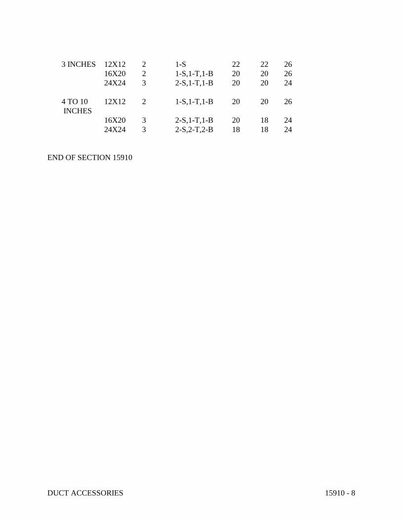
DUCT ACCESSORIES 15910 - 8
3 INCHES 12X12 2 1-S 22 22 26
16X20 2 1-S,1-T,1-B 20 20 26
24X24 3 2-S,1-T,1-B 20 20 24
4 TO 10 12X12 2 1-S,1-T,1-B 20 20 26
INCHES
16X20 3 2-S,1-T,1-B 20 18 24
24X24 3 2-S,2-T,2-B 18 18 24
END OF SECTION 15910

AIR OUTLETS AND INLETS 15932 - 1
SECTION 15932 - AIR OUTLETS AND INLETS
PART 1 - GENERAL
1.1 RELATED DOCUMENTS:
A. Drawings and general provisions of Contract, including General and Supplementary
Conditions and Division-1 Specification sections, apply to work of this section.
1.2 DESCRIPTION OF WORK:
A. Extent of air outlets and inlets work is indicated by drawings and schedules, and by
requirements of this section.
B. Types of outlets and inlets required for project include the following:
1. Ceiling air diffusers.
2. Wall registers and grilles.
3. Louvers.
C. Refer to other Division-15 sections for ductwork and duct accessories required in
conjunction with air outlets and inlets; not work of this section.
D. Refer to other Division-15 sections for balancing of air outlets and inlets; not work of this
section.
1.3 QUALITY ASSURANCE:
A. Manufacturer's Qualifications: Firms regularly engaged in manufacture of air outlets and
inlets of types and capacities required, whose products have been in satisfactory use in
similar service for not less than 5 years.
B. Codes and Standards:
1. ARI Compliance: Test and rate air outlets and inlets in accordance with ARI 650
"Standard for Air Outlets and Inlets".
2. ASHRAE Compliance: Test and rate air outlets and inlets in accordance with
ASHRAE 70 "Method of Testing for Rating the Air Flow Performance of Outlets
and Inlets".
3. AMCA Compliance: Test and rate louvers in accordance with AMCA 500 "Test
Method for Louvers, Dampers and Shutters".

AIR OUTLETS AND INLETS 15932 - 2
4. AMCA Seal: Provide louvers bearing AMCA Certified Rating Seal.
5. NFPA Compliance: Install air outlets and inlets in accordance with NFPA 90A
"Standard for the Installation of Air Conditioning and Ventilating Systems".
1.4 SUBMITTALS:
A. Product Data: Submit manufacturer's technical product data for air outlets and inlets
including the following:
1. Schedule of air outlets and inlets indicating drawing designation, room location,
number furnished, model number, size, and accessories furnished.
2. Data sheet for each type of air outlet and inlet, and accessory furnished; indicating
construction, finish, and mounting details.
3. Performance data for each type of air outlet and inlet furnished, including aspiration
ability, temperature and velocity traverses; throw and drop; and noise criteria
ratings. Indicate selections on data.
B. Shop Drawings: Submit manufacturer's assembly-type shop drawing for each type of air
outlet and inlet, indicating materials and methods of assembly of components.
C. Maintenance Data: Submit maintenance data, including cleaning instructions for finishes,
and spare parts lists. Include this data, product data, and shop drawings in maintenance
manuals; in accordance with requirements of Division 1.
1.5 PRODUCT DELIVERY, STORAGE AND HANDLING:
A. Deliver air outlets and inlets wrapped in factory-fabricated fiber-board type containers.
Identify on outside of container type of outlet or inlet and location to be installed. Avoid
crushing or bending and prevent dirt and debris from entering and settling in devices.
B. Store air outlets and inlets in original cartons and protect from weather and construction
work traffic. Where possible, store indoors; when necessary to store outdoors, store
above grade and enclose with waterproof wrapping.
PART 2 - PRODUCTS
2.1 CEILING AIR DIFFUSERS:
A. General: Except as otherwise indicated, provide manufacturer's standard ceiling air
diffusers where shown; of size, shape, capacity and type indicated; constructed of
materials and components as indicated, and as required for complete installation.
AIR OUTLETS AND INLETS 15932 - 3
B. Performance: Provide ceiling air diffusers that have, as minimum, temperature and
velocity traverses, throw and drop, and noise criteria ratings for each size device as listed
in manufacturer's current data.
C. Ceiling Compatibility: Provide diffusers with border styles that are compatible with
adjacent ceiling systems, and that are specifically manufactured to fit into ceiling module
with accurate fit and adequate support. Refer to general construction drawings and
specifications for types of ceiling systems which will contain each type of ceiling air
diffuser.
D. Types: Provide ceiling diffusers of type, capacity, and with accessories and finishes as
listed on diffuser schedule. The following requirements shall apply to nomenclature
indicated on schedule.
1. Diffuser Faces:
a. Square (SQ): Square housing, core of square concentric louvers, square or
round duct connection.
b. Rectangular (RCT): Rectangular housing, core of rectangular concentric
louvers, square or round duct connection.
2. Diffuser Mountings:
a. Stepped-Down (S-D): Diffuser housing below ceiling with perimeter flange
and gasket to seal against ceiling construction.
b. Lay-In (L-I): Diffuser housing sized to fit between ceiling exposed
suspension tee bars and rest on top surface of tee bar.
3. Diffuser Patterns:
a. Fixed (FX): Fixed position core with concentric rings or louvers for radial air
flow around entire perimeter of diffuser.
b. 2 Position (2-P): Manual 2-position core with louvers, upper position for
horizontal air flow, lower position for vertical air flow.
c. Adjustable (ADJ): Manual adjustable core with louvers, fully adjustable for
horizontal to vertical air flow.
d. Supply and Return (S & R): 2-section core, center position for return,
perimeter for supply.
e. 1 Way (1-W): Fixed louver face for 1-direction air flow, direction indicated
on drawings.
f. 2 Way (2-W): Fixed louver face for 2-direction air flow, directions indicated
on drawings.
g. 3 Way (3-W): Fixed louver face for 3-direction air flow, directions indicated
on drawings.
AIR OUTLETS AND INLETS 15932 - 4
h. 4 Way (4-W): Fixed louver face for 4-direction air flow, directions indicated
on drawings.
i. Induction (IND): Internal aspirator designed to mix air drawn into center
core with conditioned air.
j. Rearrangeable Core (R-C): Modular directional core which can be
rearranged for selected air pattern.
4. Diffuser Dampers:
a. Opposed Blade (O-B): Adjustable opposed blade damper assembly, key
operated from face of diffuser.
5. Diffuser Finishes:
a. White Enamel (W-E): Semi-gloss white enamel prime finish.
b. Aluminum Anodize (A-A): Aluminum etched and anodized, covered with
clear lacquer finish.
E. Available Manufacturers: Subject to compliance with requirements, manufacturers
offering diffusers which may be incorporated in the work include, but are not limited to,
the following:
1. Anemostat Products Div.; Dymanics Corp. of America.
2. Krueger Mfg. Co.
3. Titus Products Div.; Philips Industries, Inc.
4. Tuttle & Bailey; Div. of Interpace Corp.
2.2 WALL REGISTERS AND GRILLES:
A. General: Except as otherwise indicated, provide manufacturer's standard wall registers
and grilles where shown; of size, shape, capacity and type indicated; constructed of
materials and components as indicated, and as required for complete installation.
B. Performance: Provide wall registers and grilles that have, as minimum, temperature and
velocity traverses, throw and drop, and noise criteria ratings for each size device and listed
in manufacturer's current data.
C. Wall Compatibility: Provide registers and grilles with border styles that are compatible
with adjacent wall systems, and that are specifically manufactured to fit into wall
construction with accurate fit and adequate support. Refer to general construction
drawings and specifications for types of wall construction which will contain each type of
wall register and grille.
D. Types: Provide wall registers and grilles of type, capacity, and with accessories and
AIR OUTLETS AND INLETS 15932 - 5
finishes as listed on register and grille schedule. The following requirements shall apply
to nomenclature indicated on schedule:
1. Register and Griller Materials:
a. Aluminum Construction (AL): Manufacturer's standard extruded aluminum
frame and adjustable blades.
2. Register and Grille Faces:
a. Horizontal Straight Blades (H-S): Horizontal blades, individually adjustable,
at manufacturer's standard spacing.
b. Vertically Straight Blades (V-S): Vertical blades, individually adjustable, at
manufacturer's standard spacing.
c. Horizontal 45 Degree Fixed Blades (H-45 Degrees): Horizontal blades, fixed
at 45 degrees, at manufacturer's standard spacing.
3. Register and Grille Patterns:
a. Double Deflection (D-D): 2-sets of blades in face, rear set at 90 degrees to
face set.
4. Register and Grille Dampers:
a. Opposed Blade (O-B): Adjustable opposed blade damper assembly, key
operated from face of register.
b. Opposed Blade Fusible Link (OBFL): Opposed blade damper with spring
closing and UL-listed fusible link for 160 degrees F (71 degrees C).
5. Register and Grille Finishes:
a. White Enamel (W-E): Semi-gloss white enamel prime finish.
E. Available Manufacturers: Subject to compliance with requirements, manufacturers
offering registers and grilles which may be incorporated in the work include, but are not
limited to, the following:
1. Anemostat Products Div.; Dynamics Corp. of America.
2. Titus Products Div.; Philips Industries, Inc.
3. Krueger Mfg. Co.
4. Tuttle and Bailey, Division of Interpace Corp.
2.3 LOUVERS:

AIR OUTLETS AND INLETS 15932 - 6
A. General: Except as otherwise indicated, provide manufacturer's standard louvers where
shown; of size, shape, capacity and type indicated; constructed of materials and
components as indicated, and as required for complete installation.
B. Performance: Provide louvers that have minimum free area, and maximum pressure drop
of each type as listed in manufacturer's current data, complying with louver schedule.
C. Substrate Compatibility: Provide louvers with frame and sill styles that are compatible
with adjacent substrate, and that are specifically manufactured to fit into construction
openings with accurate fit and adequate support, for weatherproof installation. Refer to
general construction drawings and specifications for types of substrate which will contain
each type of louver.
D. Louver Screens: On inside face of exterior louvers, provide 1/2" square mesh anodized
aluminum wire bird screens mounted in removable extruded aluminum frames.
E. Available Manufacturers: Subject to compliance with requirements, manufacturers
offering louvers which may be incorporated in the work include, but are not limited to, the
following:
1. American Warming & Ventilating Inc.
2. Louvers & Dampers, Inc.
3. Penn Ventilator Co., Inc.
4. Ruskin Mfg. Co.
PART 3 - EXECUTION
3.1 INSPECTION:
A. Examine areas and conditions under which air outlets and inlets are to be installed. Do
not proceed with work until unsatisfactory conditions have been corrected.
3.2 INSTALLATION:
A. General: Install air outlets and inlets in accordance with manufacturer's written
instructions and in accordance with recognized industry practices to insure that products
serve intended function.
B. Coordinate with other work, including ductwork and duct accessories, as necessary to
interface installation of air outlets and inlets with other work.
C. Locate ceiling air diffusers, registers, and grilles, as indicated on general construction
AIR OUTLETS AND INLETS 15932 - 7
"Reflected Ceiling Plans". Unless otherwise indicated, locate units in center of acoustical
ceiling module.
3.3 SPARE PARTS:
A. Furnish to Owner, with receipt, 3 operating keys for each type of air outlet and inlet that
require them.
END OF SECTION 15932

TESTING, ADJUSTING, AND BALANCING 15990 - 1
SECTION 15990 - TESTING, ADJUSTING, AND BALANCING
PART 1 - GENERAL
1.1 RELATED DOCUMENTS:
A. Drawings and general provisions of Contract, including General and Supplementary
Conditions and Division 1 Specification sections, apply to work of this section.
B. Related Sections:
1. General requirements for testing agencies are specified in the Division-1 Section
Quality Control Services.
2. Other Division-15 Sections specify balancing devices and their installation, and
materials and installations of mechanical systems.
3. Individual Division-15 system sections specify leak testing requirements and
procedures.
1.2 SUMMARY:
A. This Section specifies the requirements and procedures total mechanical systems testing,
adjusting, and balancing. Requirements include measurement and establishment of the
fluid quantities of the mechanical systems as required to meet design specifications, and
recording and reporting the results.
B. Test, adjust, and balance the following mechanical systems:
1. Supply air systems, all pressure ranges.
2. Exhaust air systems;
3. Hydronic systems;
4. Verify temperature control system operation.
C. Test systems for proper sound and vibration levels.
D. This Section does not include:
1. testing boilers and pressure vessels for compliance with safety codes;
2. specifications for materials for patching mechanical systems;
3. specifications for materials and installation of adjusting and balancing devices. If
devices must be added to achieve proper adjusting and balancing, refer to the
respective system sections for materials and installation requirements.
4. requirements and procedures for piping and ductwork systems leakage tests.

TESTING, ADJUSTING, AND BALANCING 15990 - 2
1.3 DEFINITIONS:
A. Systems testing, adjusting, and balancing is the process of checking and adjusting all the
building environmental systems to produce the design objectives. It includes:
1. the balance of air and water distribution;
2. adjustment of total system to provide design quantities;
3. electrical measurement;
4. verification of performance of all equipment and automatic controls;
B. Test: To determine quantitative performance of equipment.
C. Adjust: To regulate the specified fluid flow rate and air patterns at the terminal
equipment (e.g., reduce fan speed, throttling).
D. Balance: To proportion flows within the distribution system (submains, branches, and
terminals) according to specified design quantities.
E. Procedure: Standardized approach and execution of sequence of work operations to yield
reproducible results.
F. Report forms: Test data sheets arranged for collecting test data in logical order for
submission and review. These data should also form the permanent record to be used as
the basis for required future testing, adjusting, and balancing.
G. Terminal: The point where the controlled fluid enters or leaves the distribution system.
These are supply inlets on water terminals, supply outlets on air terminals, return outlets
on water terminals, and exhaust or return inlets on air terminals such as registers, grilles,
diffusers, louvers, and hoods.
H. Main: Duct or pipe containing the system's major or entire fluid flow.
I. Submain: Duct or pipe containing part of the systems' capacity and serving two or more
branch mains.
J. Branch main: Duct or pipe serving two or more terminals.
K. Branch: Duct or pipe serving a single terminal.
1.4 SUBMITTALS:
A. Agency Data:

TESTING, ADJUSTING, AND BALANCING 15990 - 3
B. Engineer and Technicians Data:
1. Submit proof that the Test and Balance Engineer assigned to supervise the
procedures, and the technicians proposed to perform the procedures meet the
qualifications specified below.
C. Procedures and Agenda: Submit a synopsis of the testing, adjusting, and balancing
procedures and agenda proposed to be used for this project.
D. Maintenance Data: Submit maintenance and operating data that include how to test,
adjust, and balance the building systems. Include this information in maintenance data
specified in Division 1 and Section 15010.
E. Sample Forms: Submit sample forms, if other than those standard forms prepared by the
AABC are proposed.
F. Certified Reports: Submit testing, adjusting, and balancing reports bearing the seal and
signature of the Test and Balance Engineer. The reports shall be certified proof that the
systems have been tested, adjusted, and balanced in accordance with the referenced
standards; are an accurate representation of how the systems have been installed; are a
true representation of how the systems are operating at the completion of the testing,
adjusting, and balancing procedures; and are an accurate record of all final quantities
measured, to establish normal operating values of the systems. Follow the procedures and
format specified below:
1. Final Report: Upon verification and approval of draft reports, prepare final reports,
type written, and organized and formatted as specified below. Submit 2 complete
sets of final reports.
2. Report Format: Report forms shall be those standard forms prepared by the
referenced standard for each respective item and system to be tested, adjusted, and
balanced. Bind report forms complete with schematic systems diagrams and other
data in reinforced, vinyl, three-ring binders. Provide binding edge labels with the
project identification and a title descriptive of the contents. Divide the contents of
the binder into the below listed divisions, separated by divider tabs:
a. General Information and Summary
b. Air Systems
c. Hydronic Systems
d. Temperature Control Systems
e. Special Systems
3. Report Contents: Provide the following minimum information, forms and data:
a. General Information and Summary: Inside cover sheet to identify testing,
adjusting, and balancing agency, Contractor, Owner, Architect, Engineer, and
Project. Include addresses, and contact names and telephone numbers. Also

TESTING, ADJUSTING, AND BALANCING 15990 - 4
include a certification sheet containing the seal and name address, telephone
number, and signature of the Certified Test and Balance Engineer. Include in
this division a listing of the instrumentations used for the procedures along
with the proof of calibration.
b. The remainder of the report shall contain the appropriate forms containing as
a minimum, the information indicated on the standard report forms prepared
by the AABC and NEBB, for each respective item and system. Prepare a
schematic diagram for each item of equipment and system to accompany each
respective report form.
G. Calibration Reports: Submit proof that all required instrumentation has been calibrated to
tolerances specified in the referenced standards, within a period of six months prior to
starting the project.
1.5 QUALITY ASSURANCE:
A. Agency Qualifications:
1. Employ the services of an independent testing, adjusting, and balancing agency
meeting the qualifications specified below, to be the single source of responsibility
to test, adjust, and balance the building mechanical systems identified above, to
produce the design objectives. Services shall include checking installations for
conformity to design, measurement and establishment of the fluid quantities of the
mechanical systems as required to meet design specifications, and recording and
reporting the results.
2. An independent testing, adjusting, and balancing agency certified by Associated Air
Balance Council (AABC) in those testing and balancing disciplines required for this
project, and having at least one Professional Engineer registered in the State in
which the services are to be performed, certified by AABC as a Test and Balance
Engineer.
B. Codes and Standards:
1. AABC: "National Standards For Total System Balance".
2. ASHRAE: ASHRAE Handbook, 1984 Systems Volume, Chapter 37, Testing,
Adjusting, and Balancing.
C. Pre-Balancing Conference: Prior to beginning of the testing, adjusting, and balancing
procedures, schedule and conduct a conference with the Architect/Engineer and
representatives of installers of the mechanical systems. The objective of the conference is
final coordination and verification of system operation and readiness for testing, adjusting,
and balancing.

TESTING, ADJUSTING, AND BALANCING 15990 - 5
1.6 PROJECT CONDITIONS:
A. Systems Operation: Systems shall be fully operational prior to beginning procedures.
1.7 SEQUENCING AND SCHEDULING:
A. Test, adjust, and balance the air systems before hydronic and refrigerant systems.
B. Test, adjust and balance air conditioning systems during summer season and heating
systems during winter season, including at least a period of operation at outside conditions
within 5 deg F (3 degs C) wet bulb temperature of maximum summer design condition,
and within 10 deg F (6 deg C) dry bulb temperature of minimum winter design condition.
Take final temperature readings during seasonal operation.
PART 2 - PRODUCTS (Not Applicable)
PART 3 - EXECUTION
3.1 PRELIMINARY PROCEDURES FOR AIR SYSTEM BALANCING:
A. Before operating the system, perform these steps:
1. Obtain design drawings and specifications and become thoroughly acquainted with
the design intent.
2. Obtain copies of approved shop drawings of all air handling equipment, outlets
(supply, return, and exhaust) and temperature control diagrams.
3. Compare design to installed equipment and field installations.
4. Walk the system from the system air handling equipment to terminal units to
determine variations of installation from design.
5. Check filters for cleanliness.
6. Check dampers (both volume and fire) for correct and locked position, and
temperature control for completeness of installation before starting fans.
7. Prepare report test sheets for both fans and outlets. Obtain manufacturer's outlet
factors and recommended procedures for testing. Prepare a summation of required
outlet volumes to permit a crosscheck with required fan volumes.
8. Determine best locations in main and branch ductwork for most accurate duct
traverses.
9. Place outlet dampers in the full open position.
10. Prepare schematic diagrams of system "as-built" ductwork and piping layouts to
facilitate reporting.
11. Lubricate all motors and bearings.
12. Check fan belt tension.

TESTING, ADJUSTING, AND BALANCING 15990 - 6
13. Check fan rotation.
3.2 PRELIMINARY PROCEDURES FOR HYDRONIC SYSTEM BALANCING:
A. Before operating the system perform these steps:
1. Open valves to full open position. Close coil bypass valves.
2. Remove and clean all strainers.
3. Examine hydronic systems and determine if water has been treated and cleaned.
4. Check pump rotation.
5. Clean and set automatic fill valves for required system pressure.
6. Check expansion tanks to determine that they are not air bound and that the system
is completely full of water.
7. Check air vents at high points of systems and determine if all are installed and
operating freely (automatic type) or to bleed air completely (manual type).
8. Set temperature controls so all coils are calling for full flow.
9. Check operation of automatic bypass valves.
10. Check and set operating temperatures of chillers to design requirements.
11. Lubricate all motors and bearings.
3.3 MEASUREMENTS:
A. Provide all required instrumentation to obtain proper measurements, calibrated to the
tolerances specified in the referenced standards. Instruments shall be properly maintained
and protected against damage.
B. Provide instruments meeting the specifications of the referenced standards.
C. Use only those instruments which have the maximum field measuring accuracy and are
best suited to the function being measured.
D. Apply instrument as recommended by the manufacturer.
E. Use instruments with minimum scale and maximum subdivisions and with scale ranges
proper for the value being measured.
F. When averaging values, take a sufficient quantity of readings which will result in a
repeatability error of less than 5 percent. When measuring a single point, repeat readings
until 2 consecutive identical values are obtained.
G. Take all reading with the eye at the level of the indicated value to prevent parallax.
H. Use pulsation dampeners where necessary to eliminate error involved in estimating
average of rapidly fluctuation readings.
TESTING, ADJUSTING, AND BALANCING 15990 - 7
I. Take measurements in the system where best suited to the task.
3.4 PERFORMING TESTING, ADJUSTING, AND BALANCING:
A. Perform testing and balancing procedures on each system identified, in accordance with
the detailed procedures outlined in the referenced standards.
B. Cut insulation, ductwork, and piping for installation of test probes to the minimum extent
necessary to allow adequate performance of procedures.
C. Patch insulation, ductwork, and housings, using materials identical to those removed.
D. Seal ducts and piping, and test for and repair leaks.
E. Seal insulation to re-establish integrity of the vapor barrier.
F. Mark equipment settings, including damper control positions, valve indicators, fan speed
control levers, and similar controls and devices, to show final settings. Mark with paint or
other suitable, permanent identification materials.
G. Retest, adjust, and balance systems subsequent to significant system modifications, and
resubmit test results.
3.5 RECORD AND REPORT DATA:
A. Record all data obtained during testing, adjusting, and balancing in accordance with, and
on the forms recommended by the referenced standards, and as approved on the sample
report forms.
B. Prepare report of recommendations for correcting unsatisfactory mechanical performances
when system cannot be successfully balanced.
END OF SECTION 15990

BASIC ELECTRICAL MATERIALS AND METHODS 16050 - 1
SECTION 16050 - BASIC ELECTRICAL MATERIALS AND METHODS
PART 1 - GENERAL
1.1 RELATED DOCUMENTS
A. Drawings and general provisions of the Contract, including General and Supplementary
Conditions and Division 1 Specification Sections, apply to this Section.
1.2 SUMMARY
A. This Section includes the following electrical materials and methods:
1. Building wire, connectors, and splices for branch circuits and feeders.
2. Supporting devices for electrical components.
3. Concrete equipment bases.
4. Electrical identification.
5. Cutting and patching for electrical construction.
6. Touchup painting.
7. Meter sockets.
1.3 SUBMITTALS
A. General: Submit each item in this Article according to the Conditions of the Contract and
Division 1 Specification Sections.
B. Product Data for each type of product specified.
C. Shop Drawings detailing fabrication and installation of supports and anchorage for
electrical items.
D. Samples of color, lettering style, and other graphic representation required for each
identification product for Project.
1.4 QUALITY ASSURANCE
A. Comply with NFPA 70 for components and installation.
B. Listing and Labeling: Provide products specified in this Section that are listed and labeled.

BASIC ELECTRICAL MATERIALS AND METHODS 16050 - 2
1. The Terms "Listed and Labeled": As defined in the National Electrical Code, Article
100.
2. Listing and Labeling Agency Qualifications: A "Nationally Recognized Testing
Laboratory" (NRTL) as defined in OSHA Regulation 1910.7.
1.5 SEQUENCING AND SCHEDULING
A. Coordinate electrical equipment installation with other building components.
B. Arrange for chases, slots, and openings in building structure during progress of construction
to allow for electrical installations.
C. Coordinate installing required supporting devices and set sleeves in poured-in-place
concrete and other structural components as they are constructed.
D. Sequence, coordinate, and integrate installing electrical materials and equipment for
efficient flow of the Work. Coordinate installing large equipment requiring positioning
prior to closing in the building.
E. Coordinate connecting electrical service to components furnished under other Sections.
F. Coordinate connecting electrical systems with exterior underground and overhead utilities
and services. Comply with requirements of governing regulations, franchised service
companies, and controlling agencies.
G. Coordinate requirements for access panels and doors where electrical items requiring access
are concealed by finished surfaces.
H. Coordinate installing electrical identification after completion of finishing where
identification is applied to field-finished surfaces.
I. Coordinate installing electrical identifying devices and markings prior to installing
acoustical ceilings and similar finishes that conceal such items.
PART 2 - PRODUCTS
2.1 BUILDING WIRE
A. Description: Single conductor, copper. Solid conductor for No. 10 AWG and smaller;
stranded conductor for larger than No. 10 AWG.
B. Thermoplastic Insulated Wire: Conform to NEMA WC 5.
BASIC ELECTRICAL MATERIALS AND METHODS 16050 - 3
C. Cross-Linked, Polyethylene Insulated Wire: Conform to NEMA WC 7.
D. Connectors and Splices: Units of size, ampacity rating, material, type, and class suitable for
service indicated. Select to comply with Project's installation requirements.
2.2 SUPPORTING DEVICES
A. Channel and angle support systems, hangers, anchors, sleeves, brackets, fabricated items,
and fasteners are designed to provide secure support from the building structure for
electrical components.
1. Material: Steel, except as otherwise indicated, protected from corrosion with zinc
coating or with treatment of equivalent corrosion resistance using approved
alternative finish or inherent material characteristics.
2. Metal Items for Use Outdoors or in Damp Locations: Hot-dip galvanized steel,
except as otherwise indicated.
B. Steel channel supports have 9/16-inch (14-mm) diameter holes at a maximum of 8 inches
(203 mm) o.c., in at least 1 surface.
1. Fittings and accessories mate and match with channels and are from the same
manufacturer.
C. Nonmetallic Channel and Angle Systems: Structural-grade, factory-formed, fiberglass-
resin channels and angles with 9/16-inch (14-mm) diameter holes at a maximum of 8 inches
(203 mm) o.c., in at least 1 surface.
1. Fittings and accessories mate and match with channels or angles and are from the
same manufacturer.
2. Fitting and Accessory Material: Same as channels and angles, except metal items
may be stainless steel.
D. Raceway and Cable Supports: Manufactured clevis hangers, riser clamps, straps, threaded
C-clamps with retainers, ceiling trapeze hangers, wall brackets, and spring steel clamps or
"click"- type hangers.
E. Sheet-Metal Sleeves: 0.0276-inch (0.7-mm) or heavier galvanized sheet steel, round tube,
closed with welded longitudinal joint.
F. Pipe Sleeves: ASTM A 53, Type E, Grade A, Schedule 40, galvanized steel, plain ends.
G. Cable Supports for Vertical Conduit: Factory-fabricated assembly consisting of threaded
body and insulating wedging plug for nonarmored electrical cables in riser conduits. Plugs
have number and size of conductor gripping holes as required to suit individual risers.
BASIC ELECTRICAL MATERIALS AND METHODS 16050 - 4
Body constructed of malleable iron casting with hot-dip galvanized finish.
H. Expansion Anchors: Carbon-steel wedge or sleeve type.
I. Toggle Bolts: All-steel springhead type.
J. Powder-Driven Threaded Studs: Heat-treated steel.
2.3 CONCRETE EQUIPMENT BASES
A. Forms and Reinforcing Materials: As specified in Division 3 Section "Cast-in-Place
Concrete."
B. Concrete: 3000-psi (20.7-MPa), 28-day compressive strength.
2.4 ELECTRICAL IDENTIFICATION
A. Manufacturer's Standard Products: Where more than one type is listed for a specified
application, selection is Installer's option, but provide single type for each application
category. Use colors prescribed by ANSI A13.1, NFPA 70, and these Specifications.
B. Colored Adhesive Marking Tape for Raceways, Wires, and Cables: Self-adhesive vinyl
tape not less than 3 mils thick by 1 inch wide (0.08 mm thick by 25 mm wide).
C. Underground Line Warning Tape: Permanent, bright-colored, continuous-printed, vinyl
tape with the following features:
1. Size: Not less than 4 mils thick by 6 inches wide (0.102 mm thick by 152 mm wide).
a. Compounded for permanent direct-burial service.
b. Printed Legend: Indicates type of underground line.
D. Tape Markers: Vinyl or vinyl-cloth, self-adhesive, wraparound type with preprinted
numbers and letters.
E. Color-Coding Cable Ties: Type 6/6 nylon, self-locking type. Colors to suit coding scheme.
F. Engraved, Plastic-Laminated Labels, Signs, and Instruction Plates: Engraving stock,
melamine plastic laminate punched for mechanical fasteners 1/16-inch (1.6-mm) minimum
thick for signs up to 20 sq. in. (129 sq. cm), 1/8 inch (3.2 mm) thick for larger sizes.
Engraved legend in black letters on white face.
G. Interior Warning and Caution Signs: Preprinted, aluminum, baked-enamel finish signs,
punched for fasteners, with colors, legend, and size appropriate to the application.
BASIC ELECTRICAL MATERIALS AND METHODS 16050 - 5
H. Fasteners for Plastic-Laminated and Metal Signs: Self-tapping stainless-steel screws or
No. 10/32 stainless-steel machine screws with nuts and flat and lock washers.
2.5 METER SOCKETS
A. Meter sockets comply with serving utility company requirements.
2.6 TOUCHUP PAINT
A. For Equipment: Provided by equipment manufacturer and selected to match equipment
finish.
B. For Nonequipment Surfaces: Matching type and color of undamaged, existing adjacent
finish.
C. For Galvanized Surfaces: Zinc-rich paint recommended by item manufacturer.
PART 3 - EXECUTION
3.1 EQUIPMENT INSTALLATION REQUIREMENTS
A. Install components and equipment to provide the maximum possible headroom where
mounting heights or other location criteria are not indicated.
B. Install items level, plumb, and parallel and perpendicular to other building systems and
components, except where otherwise indicated.
C. Install equipment to facilitate service, maintenance, and repair or replacement of
components. Connect for ease of disconnecting, with minimum interference with other
installations.
D. Give right of way to raceways and piping systems installed at a required slope.
3.2 WIRING METHODS
A. Feeders: Type THHN/THWN, copper conductor, in raceway, except as otherwise
indicated.
B. Underground Feeders: Type UF, copper conductor, 90C insulation, in raceway, except as
otherwise indicated.
BASIC ELECTRICAL MATERIALS AND METHODS 16050 - 6
C. Branch Circuits: Type THHN/THWN, in raceway.
D. Class 2 and Class 3 Control Circuits: Type THHN/THWN, in raceway.
3.3 ELECTRICAL SUPPORTING METHODS
A. Damp Locations and Outdoors: Hot-dip galvanized materials or nonmetallic, U-channel
system components.
B. Dry Locations: Steel materials.
C. Conform to manufacturer's recommendations for selecting supports.
D. Strength of Supports: Adequate to carry all present and future loads, times a safety factor
of at least 4; 200-lb- (90-kg-) minimum design load.
3.4 INSTALLATION
A. Install wires in raceway according to manufacturer's written instructions and NECA's
"Standard of Installation."
B. Conductor Splices: Keep to the minimum and comply with the following:
1. Install splices and taps that possess equivalent or better mechanical strength and
insulation ratings than unspliced conductors.
2. Use splice and tap connectors that are compatible with conductor material.
C. Wiring at Outlets: Install with at least 12 inches (300 mm) of slack conductor at each
outlet.
D. Connect outlets and components to wiring systems and to ground as indicated and
instructed by manufacturer. Tighten connectors and terminals, including screws and bolts,
according to equipment manufacturer's published torque-tightening values for equipment
connectors. Where manufacturer's torquing requirements are not indicated, tighten
connectors and terminals according to tightening requirements specified in UL 486A.
E. Install devices to securely and permanently fasten and support electrical components.
F. Raceway Supports: Comply with NFPA 70 and the following requirements:
1. Conform to manufacturer's recommendations for selecting and installing supports.
2. Install individual and multiple raceway hangers and riser clamps to support raceways.
BASIC ELECTRICAL MATERIALS AND METHODS 16050 - 7
Provide U bolts, clamps, attachments, and other hardware necessary for hanger
assembly and for securing hanger rods and conduits.
3. Support parallel runs of horizontal raceways together on trapeze- or bracket-type
hangers.
4. Spare Capacity: Size supports for multiple conduits so capacity can be increased by a
25 percent minimum in the future.
5. Support individual horizontal raceways with separate, malleable iron pipe hangers or
clamps.
6. Hanger Rods: 1/4-inch (6-mm) diameter or larger threaded steel, except as otherwise
indicated.
7. Spring Steel Fasteners: Specifically designed for supporting single conduits or
tubing. May be used in lieu of malleable iron hangers for 1-1/2-inch (38-mm) and
smaller raceways serving lighting and receptacle branch circuits above suspended
ceilings and for fastening raceways to channel and slotted angle supports.
8. In vertical runs, arrange support so the load produced by the weight of the raceway
and the enclosed conductors is carried entirely by the conduit supports, with no
weight load on raceway terminals.
G. Vertical Conductor Supports: Install simultaneously with conductors.
H. Miscellaneous Supports: Install metal channel racks for mounting cabinets, panelboards,
disconnects, control enclosures, pull boxes, junction boxes, transformers, and other devices
except where components are mounted directly to structural features of adequate strength.
I. In open overhead spaces, cast boxes threaded to raceways need not be separately supported,
except where used for fixture support; support sheet-metal boxes directly from the building
structure or by bar hangers. Where bar hangers are used, attach the bar to raceways on
opposite sides of the box and support the raceway with an approved fastener not more than
24 inches (610 mm) from the box.
J. Sleeves: Install for cable and raceway penetrations of concrete slabs and walls, except
where core-drilled holes are used. Install for cable and raceway penetrations of masonry
and fire-rated gypsum walls and of all other fire-rated floor and wall assemblies. Install
sleeves during erection of concrete and masonry walls.
K. Firestopping: Apply to cable and raceway penetrations of fire-rated floor and wall
assemblies. Perform firestopping as specified in Division 7 Section "Firestopping" to
reestablish the original fire-resistance rating of the assembly at the penetration.
L. Fastening: Unless otherwise indicated, securely fasten electrical items and their supporting
hardware to the building structure. Perform fastening according to the following:
1. Fasten by means of wood screws or screw-type nails on wood; toggle bolts on hollow
masonry units; concrete inserts or expansion bolts on concrete or solid masonry; and
by machine screws, welded threaded studs, or spring-tension clamps on steel.
BASIC ELECTRICAL MATERIALS AND METHODS 16050 - 8
2. Threaded studs driven by a powder charge and provided with lock washers and nuts
may be used instead of expansion bolts, machine screws, or wood screws.
3. Welding to steel structure may be used only for threaded studs, not for conduits, pipe
straps, or any other items.
4. In partitions of light steel construction use sheet-metal screws.
5. Drill holes in concrete beams so holes more than 1-1/2 inches (38 mm) deep do not
cut main reinforcing bars.
6. Drill holes in concrete so holes more than 3/4 inch (19 mm) deep do not cut main
reinforcing bars.
7. Fill and seal holes drilled in concrete and not used.
8. Select fasteners so the load applied to any fastener does not exceed 25 percent of the
proof-test load.
M. Install concrete pads and bases according to requirements of Division 3 Section "Cast-in-
Place Concrete."
N. Install utility-metering equipment according to utility company's written requirements.
Provide grounding and empty conduits as required by company.
O. Install identification devices where required.
1. Install labels where indicated and at locations for best convenience of viewing
without interference with operation and maintenance of equipment.
2. Coordinate names, abbreviations, colors, and other designations used for electrical
identification with corresponding designations indicated on the Contract Documents
or required by codes and standards. Use consistent designations throughout the
Project.
3. Self-Adhesive Identification Products: Clean surfaces of dust, loose material, and
oily films before applying.
4. Identify Paths of Underground Electrical Lines: During trench backfilling, for
exterior underground power, control, signal, and communication lines, install
continuous underground plastic line marker located directly above power and
communication lines. Locate 6 to 8 inches (150 to 200 mm) below finished grade.
Where multiple lines installed in a common trench or concrete envelope do not
exceed an overall width of 16 inches (400 mm), use a single line marker.
5. For panelboards, provide framed, typed circuit schedules with explicit description
and identification of items controlled by each individual breaker.
3.5 CUTTING AND PATCHING
A. Cut, channel, chase, and drill floors, walls, partitions, ceilings, and other surfaces necessary
for electrical installations. Perform cutting by skilled mechanics of the trades involved.
B. Repair disturbed surfaces to match adjacent undisturbed surfaces.

BASIC ELECTRICAL MATERIALS AND METHODS 16050 - 9
3.6 TOUCHUP PAINTING
A. Thoroughly clean damaged areas and provide primer, intermediate, and finish coats to suit
the degree of damage at each location.
B. Follow paint manufacturer's written instructions for surface preparation and for timing and
application of successive coats.
END OF SECTION 16050
WIRES AND CABLES 16120 - 1
SECTION 16120 - WIRES AND CABLES
PART 1 - GENERAL
1.1 RELATED DOCUMENTS
A. Drawings and general provisions of the Contract, including General and Supplementary
Conditions and Division 1 Specification Sections, apply to this Section.
1.2 SUMMARY
A. This Section includes building wires and cables and associated splices, connectors, and
terminations for wiring systems rated 600 volts and less.
B. Related Sections: The following Sections contain requirements that relate to this Section:
1. Division 16 Section "Basic Electrical Materials and Equipment."
1.3 SUBMITTALS
A. General: Submit the following according to the Conditions of the Contract and Division 1
Specification Sections.
B. Field test reports indicating and interpreting test results relative to compliance with
performance requirements of testing standard.
1.4 QUALITY ASSURANCE
A. Testing Firm Qualifications: In addition to the requirements specified in Division 1
Section "Quality Control Services," an independent testing firm shall meet OSHA criteria
for accreditation of testing laboratories, Title 29, Part 1907, or shall be a full member
company of the International Electrical Testing Association (NETA).
1. Testing Firm's Field Supervisor Qualifications: A person currently certified by the
NETA National Institute for Certification in Engineering Technologies to supervise
on-site testing specified in Part 3.
B. Comply with NFPA 70 "National Electrical Code" for components and installation.
C. Listing and Labeling: Provide products specified in this Section that are listed and

WIRES AND CABLES 16120 - 2
labeled.
1. The Terms "Listed and Labeled": As defined in the "National Electrical Code,"
Article 100.
2. Listing and Labeling Agency Qualifications: A "Nationally Recognized Testing
Laboratory" (NRTL) as defined in OSHA Regulation 1910.7.
1.5 SEQUENCING AND SCHEDULING
A. Coordination: Coordinate layout and installation of cable with other installations.
1. Revise locations and elevations from those indicated as required to suit field
conditions and as approved by the Architect.
1.6 DELIVERY, STORAGE, AND HANDLING
A. Deliver wire and cable according to NEMA WC-26.
1.7 CONDUCTOR CODING
A. Color code conductors in accordance with NEC.
1. 208Y/120 volts:
a. Phase A: Black
b. Phase B: Red
c. Phase C: Blue
d. Neutral: White
e. Ground: Green
2. No. 12 and No. 10 shall have continuous insulation color.
3. Color code conductors larger than No. 10 which do not have continuous insulation
color by application of at least two laps of colored tape on each conductor at all
points of access.
B. Conductor sizes are based on copper unless otherwise indicated.
C. Two or three single phase circuits may be installed in one conduit using conductors of
different phases and a common neutral. Do not use common neutral on ground fault
circuits. Do not install more than three phases in one conduit unless specifically
indicated.
PART 2 - PRODUCTS

WIRES AND CABLES 16120 - 3
2.1 MANUFACTURERS
A. Available Manufacturers: Subject to compliance with requirements, manufacturers
offering products that may be incorporated in the Work include, but are not limited to, the
following:
1. Wires and Cables:
a. American Insulated Wire Corporation, Leviton Manufacturing Co.
b. Brand-Rex Cable Systems, Brintec Corp.
c. Carol Cable Company, Inc.
d. Senator Wire & Cable Co.
e. Southwire Co.
2. Connectors for Wires and Cables:
a. AFC, Monogram Co.
b. AMP, Inc.
c. Anderson, Square D Co.
d. Electrical Products Division, 3M Co.
e. O-Z/Gedney Unit, General Signal.
2.2 BUILDING WIRES AND CABLES
A. UL-listed building wires and cables with conductor material, insulation type, cable
construction, and rating as specified in Part 3 "Applications" Article.
B. Rubber Insulation: Conform to NEMA WC 3.
C. Thermoplastic Insulation: Conform to NEMA WC 5.
D. Cross-Linked Polyethylene Insulation: Conform to NEMA WC 7.
E. Ethylene Propylene Rubber Insulation: Conform to NEMA WC 8.
F. Solid conductor for 10 AWG and smaller; stranded conductor for larger than 10 AWG.
2.3 CONNECTORS AND SPLICES
A. UL-listed factory-fabricated wiring connectors of size, ampacity rating, material, and type
and class for application and for service indicated. Select to comply with Project's
installation requirements and as specified in Part 3 "Applications" Article.
WIRES AND CABLES 16120 - 4
2.4 SPLICES, TAPS, AND CONNECTORS
A. Splices and taps smaller than No. 6 AWG: Use insulated conical spring type connectors.
B. Splices and taps No. 6 AWG and larger: Use compression connectors with prestretched
insulation to equal insulation of wire being spliced.
C. All cable terminations shall be suitable for the cable type, size, and number of conductors.
2.5 VERTICAL RUNS
A. Conductors in vertical runs shall be supported by split wedge type fittings which clamp
each conductor and tighten under weight of conductor.
2.6 INSTALLATION
A. Install wiring in conduit unless otherwise shown.
B. Install splice-free conductors within raceways. Make splices only at accessible locations.
2.7 TIES
A. Form and tie all wiring in panelboards, switchboards, switchgear and control panels.
B. Bundle wiring and tie at 6 inch intervals.
C. Train bundles parallel to adjacent enclosure surfaces and in such a manner as to prevent
abrasion due to rubbing or contact with buswork or other non-associated wiring.
2.8 IDENTIFICATION
A. Identify each wire using wire markers at all points of access.
B. Identify lighting and receptacle branch circuit wiring by panelboard name and circuit
number.
C. Identify motor branch circuit wiring by name, circuit number and phase.
D. Identify feeders by name of equipment from which they originate, circuit number and
phase.

WIRES AND CABLES 16120 - 5
E. Install identification labels in all junction boxes and terminal points so as to be clearly
visible.
2.9 TESTING
A. Cables #8 and Smaller:
1. Check for physical damage to conductor and insulation.
2. Verify proper color coding.
3. Test for continuity, shorts to ground, and reverse polarity.
4. Check for terminations for proper connections.
B. Cables #6 and Larger:
1. Test all items listed in Part A above.
2. Test cable in accordance with NETA ATS-1991, Section 7.3.
C. Testing Authority:
1. The testing Authority shall be the electrical contractor.
D. Test Report:
1. Test report shall list each cable, date tested, test instruments, personnel who
conducted test, and test results.
2. All cables which fail test shall be repaired or replaced and retested. Include all
information listed above on retest.
3. Report shall be supervised by the Testing Authority who shall be responsible for the
test and signed by the representative of the Testing Authority.
4. Submit test report after all cables have passed test.
PART 3 - EXECUTION
3.1 EXAMINATION
A. Examine raceways and building finishes to receive wires and cables for compliance with
installation tolerances and other conditions. Do not proceed with installation until
unsatisfactory conditions have been corrected.
3.2 APPLICATIONS
WIRES AND CABLES 16120 - 6
A. Service Entrance: Type RHW or THWN, copper conductor, in raceway.
B. Feeders: Type THHN/THWN, copper conductor, in raceway.
C. Branch Circuits: Type THHN/THWN, copper conductor, in raceway.
D. Fire Alarm Circuits: Type THHN/THWN, copper conductor, in raceway.
E. Class 2 Control Circuits: Type THHN/THWN, copper conductor, in raceway.
3.3 INSTALLATION
A. Install wires and cables as indicated, according to manufacturer's written instructions and
the NECA "Standard of Installation."
1. Use pulling compound or lubricant where necessary; compound used must not
deteriorate conductor or insulation.
2. Use pulling means, including fish tape, cable, rope, and basket-weave wire/cable
grips that will not damage cables or raceway.
B. Install exposed cable, parallel and perpendicular to surfaces or exposed structural
members, and follow surface contours where possible.
C. Conductor Splices: Keep to minimum.
1. Install splices and tapes that possess equivalent or better mechanical strength and
insulation ratings than conductors being spliced.
2. Use splice and tap connectors that are compatible with conductor material.
D. Wiring at Outlets: Install with at least 12 inches (300 mm) of slack conductor at each
outlet.
E. Connect outlets and components to wiring and to ground as indicated and instructed by
manufacturer. Tighten connectors and terminals, including screws and bolts, according to
equipment manufacturer's published torque-tightening values for equipment connectors.
Where manufacturer's torquing requirements are not indicated, tighten connectors and
terminals according to tightening torques specified in UL Standard 486A.
3.4 FIELD QUALITY CONTROL
A. Testing: Upon installation of wires and cables and before electrical circuitry has been
energized, demonstrate product capability and compliance with requirements.
WIRES AND CABLES 16120 - 7
1. Procedures: Perform each visual and mechanical inspection and electrical test
stated in NETA Standard ATS, Section 7.3.1. Certify compliance with test
parameters.
B. Correct malfunctioning products at site, where possible, and retest to demonstrate
compliance; otherwise, remove and replace with new units, and retest.
END OF SECTION 16120

DISCONNECT SWITCHES AND CIRCUIT BREAKERS 16476 - 1
SECTION 16476 - DISCONNECT SWITCHES AND CIRCUIT BREAKERS
PART 1 - GENERAL
1.1 RELATED DOCUMENTS
A. Drawings and general provisions of the Contract, including General and Supplementary
Conditions and Division 1 Specification Sections, apply to this Section.
1.2 SUMMARY
A. This Section includes individually mounted switches and circuit breakers used for the
following:
1. Feeder and equipment disconnect switches.
2. Motor disconnect switches.
B. Related Sections: The following Sections contain requirements that relate to this Section:
1. Division 16 Section "Wiring Devices" for attachment plugs and receptacles, and snap
switches used for disconnect switches.
2. Division 16 Section "Switchboards" for individually enclosed, fused power-circuit
devices used as feeder disconnect switches.
3. Division 16 Section "Fuses" for fuses in fusible disconnect switches.
1.3 SUBMITTALS
A. General: Submit each item in this Article according to the Conditions of the Contract and
Division 1 Specification Sections.
B. Product Data for disconnect switches, circuit breakers, and accessories specified in this
Section.
C. Product Data for switches, circuit breakers, and accessories specified in this Section.
Include the following:
1. Descriptive data and time-current curves.
2. Let-through current curves for circuit breakers with current-limiting characteristics.
3. Coordination charts and tables and related data.
D. Wiring diagrams detailing wiring for power and control systems and differentiating

DISCONNECT SWITCHES AND CIRCUIT BREAKERS 16476 - 2
between manufacturer-installed and field-installed wiring.
E. Maintenance data for tripping devices to include in the operation and maintenance manual
specified in Division 1.
1.4 QUALITY ASSURANCE
A. Source Limitations: Obtain disconnect switches and circuit breakers from one source and
by a single manufacturer.
B. Comply with NFPA 70 for components and installation.
C. Listing and Labeling: Provide disconnect switches and circuit breakers specified in this
Section that are listed and labeled.
1. The Terms "Listed" and "Labeled": As defined in the National Electrical Code,
Article 100.
2. Listing and Labeling Agency Qualifications: A "Nationally Recognized Testing
Laboratory" (NRTL) as defined in OSHA Regulation 1910.7.
PART 2 - PRODUCTS
2.1 MANUFACTURERS
A. Available Manufacturers: Subject to compliance with requirements, manufacturers offering
disconnect switches and circuit breakers that may be incorporated into the Work include,
but are not limited to, the following:
1. Fusible Switches:
a. Eaton Corp.; Cutler-Hammer Products.
b. General Electric Co.; Electrical Distribution and Control Division.
c. General Switch Corp.
d. Siemens Energy & Automation, Inc.
e. Square D Co.
f. Westinghouse Electric Corp.; Distribution & Control Business Unit.
2. Molded-Case Circuit Breakers:
a. American Circuit Breaker Corp.
b. Eaton Corp.; Cutler-Hammer Products.
c. General Electric Co.; Electrical Distribution and Control Division.
DISCONNECT SWITCHES AND CIRCUIT BREAKERS 16476 - 3
d. General Switch Corp.
e. Klockner-Moeller.
f. Siemens Energy & Automation, Inc.
g. Square D Co.
h. Westinghouse Electric Corp.; Distribution & Control Business Unit.
3. Molded-Case, Current-Limiting Circuit Breakers:
a. General Electric Co.; Electrical Distribution and Control Division.
b. Siemens Energy & Automation, Inc.
c. Square D Co.
d. Westinghouse Electric Corp.; Distribution & Control Business Unit.
4. Integrally Fused, Molded-Case Circuit Breakers:
a. General Electric Co.; Electrical Distribution and Control Division.
b. Siemens Energy & Automation, Inc.
c. Westinghouse Electric Corp.; Distribution & Control Business Unit.
2.2 DISCONNECT SWITCHES
A. Enclosed, Fusible Switch, 800 A and Smaller: NEMA KS 1, Type HD, clips to
accommodate specified fuses, enclosure consistent with environment where located, handle
lockable with 2 padlocks, and interlocked with cover in CLOSED position.
B. Enclosure: NEMA KS 1, Type 1, unless otherwise specified or required to meet
environmental conditions of installed location.
1. Outdoor Locations: Type 3R.
2. Other Wet or Damp Indoor Locations: Type 4.
2.3 ENCLOSED CIRCUIT BREAKERS
A. Enclosed, Molded-Case Circuit Breaker: NEMA AB 1, with lockable handle.
B. Characteristics: Frame size, trip rating, number of poles, and auxiliary devices as indicated
and interrupting rating to meet available fault current.
C. Application Listing: Appropriate for application, including switching fluorescent lighting
loads or heating, air-conditioning, and refrigerating equipment.
D. Circuit Breakers, 200 A and Larger: Trip units interchangeable within frame size.

DISCONNECT SWITCHES AND CIRCUIT BREAKERS 16476 - 4
E. Circuit Breakers, 400 A and Larger: Field-adjustable, short-time and continuous-current
settings.
F. Current-Limiting Trips: Where indicated, let-through ratings less than NEMA FU 1,
Class RK-5.
G. Current Limiters: Where indicated, integral fuse listed for circuit breaker.
H. Lugs: Mechanical lugs and power-distribution connectors for number, size, and material of
conductors indicated.
I. Shunt Trip: Where indicated.
J. Accessories: As indicated.
K. Safety switches shall be enclosed heavy duty type (Type HD) with quick-make, quick-break
mechanism and external pad-lockable operating handle.
L. Safety switches shall be rated 240 volts as applicable for the voltage and number of poles
required for the circuit. They shall be horsepower rated for the motor they serve when used
in motor circuits.
M. Lugs shall be rated for copper or aluminum conductors and removable from the front.
Provide a ground wire lug of suitable size in the enclosure. Provide isolated solid neutral
bar for switches with neutral in the circuit.
N. Fusible switches shall have rejection clips to accept Class R fuses only.
2.4 CIRCUIT BREAKERS
A. Ratings and special features shall be indicated. All circuit breakers shall be bolt on type
and shall have terminal lugs. UL listed for the cable they feed.
B. The circuit breaker shall be completely enclosed in a molded case. Ampere, voltage,
frequency, and interrupting ratings shall be clearly marked.
C. The interrupting rating of the circuit breakers shall be equal to or greater than the available
short circuit current at the line terminals as shown on the plans.\
2.5 RESTRICTIONS
A. Circuit breakers shall be arranged A-B-C top to bottom, left to right, front to back.
B. Circuit breakers that connect to stacked bus bar bussing shall have their phase letters clearly
DISCONNECT SWITCHES AND CIRCUIT BREAKERS 16476 - 5
identified on the load side terminals by permanent markings clearly visible to eliminate the
possibility of reversing phase rotation. A sample will be required to verify compliance.
PART 3 - EXECUTION
3.1 INSTALLATION
A. Install disconnect switches and circuit breakers in locations as indicated, according to
manufacturer's written instructions.
B. Install disconnect switches and circuit breakers level and plumb.
C. Connect disconnect switches and circuit breakers and components to wiring system and to
ground as indicated and instructed by manufacturer.
1. Tighten electrical connectors and terminals according to manufacturer's published
torque-tightening values. Where manufacturer's torque values are not indicated, use
those specified in UL 486A and UL 486B.
D. Identify each disconnect switch and circuit breaker according to requirements specified in
Division 16 Section "Basic Electrical Materials and Methods."
3.2 FIELD QUALITY CONTROL
A. Testing: After installing disconnect switches and circuit breakers and after electrical
circuitry has been energized, demonstrate product capability and compliance with
requirements.
1. Procedures: Perform each visual and mechanical inspection and electrical test stated
in NETA ATS, Section 7.5 for disconnect switches and Section 7.6 for molded-case
circuit breakers. Certify compliance with test parameters.
B. Correct malfunctioning units on-site, where possible, and retest to demonstrate compliance;
otherwise, remove and replace with new units and retest.
3.3 ADJUSTING
A. Set field-adjustable disconnect switches and circuit-breaker trip ranges as indicated.
3.4 CLEANING
DISCONNECT SWITCHES AND CIRCUIT BREAKERS 16476 - 6
A. After completing system installation, including outlet fittings and devices, inspect exposed
finish. Remove burrs, dirt, and construction debris and repair damaged finish including
chips, scratches, and abrasions.
END OF SECTION 16476


