

SPPC Collimation Design
Jianquan Yang, Ye Zou, Jingyu Tang
Institute of High Energy Physics (IHEP), CAS, Beijing
CEPC international workshopNov. 13rd, 2018
Outline
• Introduction
• Motivations and goals
• Optics design
• Multi-particle simulation results
• Protection scheme of the SC magnets
• Conclusions
• Next to do

Introduction Layout of SPPC
Parameter Unit Value
Proton energy TeV 37.5
Nominal luminosity cm-2s-1 1.01×1035
Number of IPs - 2
Bunch separation ns 25
Bunch filling factor - 0.756
Number of bunches - 10080
Bunch population × 1011 1.5
Normalized rms transverse
emittance
μm 2.4
rms bunch length mm 75.5
Stored beam energy per beam GJ 9.1

Introductions The novel collimation method
• Single diffractive scattering
• The particles experiencing single diffractive interactions in the primary collimators will loss in the cold magnets of DS
• In order to deal with these particle losses, we can arrange the transverse and momentum collimation in the same cleaning insertion
Loss from 7 TeV to 37.5 TeV factor 7
From M. Fiascaris

Introduction Novel collimation method
• Length 4300 m• Arrange the transverse and momentum
collimation in the same long straight insertion
• Four groups of SC dipoles are used to produce required dispersion for momentum collimation cancel the dispersion at the section end
• Betatron collimation requires significantly longer space for multi-stage collimation and the two proton beams
• Compatibility of two sets of collimation system for each beam needs to be considered

Motivations Beam loss mechanism
• Regular proton losses
Injection energy Collision energy
IBS: blt ~40 h ~ 170 h
Touschek: blt ~8000 h ~ 30000h
Beam-gas: egt ~35 h ~ 800 h
Beam-Beam collision: egt ~120 h
Blt: beam lifetimeEgt: emittance growth time
• Irregular proton losses• Operational errors
• Equipment failures

Motivations Multi-stage collimation method
• Primary collimators scatter the primary halo
• Secondary collimators intercept and stop part
of the scattered particles
• Absorbers stop the showers
• Tertiary collimators protect the SC dipoles or
Quadrupole triplets in IP
• TCLs absorb physics debris
• 98 two-sided and 2 one-sided movable collimators;
396 degrees of freedom
• Two warm interaction regions are used to provide betatron and momentum collimation
From S. Redaelli

Goals Collimation efficiency
Main functionality• Quench prevention:
for SPPC: • Halo particles cleaning• Machine protection: prevent damaging radiation-sensitive devices• Radiation losses concentration: hands-on maintenance• Cleaning physics debris: collision products• Optimizing background: in the experiments• halo diagnostics
𝜂𝑐 =𝜏min · 𝑅𝑞
𝑁𝑡𝑜𝑡𝑞
𝜂𝑐 < 3.55×10⁻⁷ m−1
3
8 21.7 10qR E

Optics design Requirements I
• Betatron Collimation• Large beta function
>> maximize the impact parameters and reduce the possibility of collision between the beam halo and the collimator surface
>> reduce the impedance induced by collimators
• Phase advances greater than 2π
• Momentum Collimation• βx lower than in betatron collimation
>> maximize the momentum dispersion resolution (normalized dispersion)
• Normalized dispersion at primary momentum collimator satisfy:
𝜒𝐷,prim 𝑛1 ≥𝑛1𝜒𝐷,arc
𝐴arc,inj 𝛿𝑝=0 −(𝑛22−𝑛1
2)1/2 & 𝐷𝑥
′
𝐷𝑥= −
𝛼𝑥
𝛽𝑥
>> make sure the cut of the secondary halo is independent of the particle momentum

Optics design
Lattice scheme IILattice scheme I

Optics design Lattice scheme II
• Compatibility with two sets of collimation system for each beam• Quadrupoles with twin apertures are installed in the overlapping region
between the two beam• Quadrupoles with single aperture are installed in the position with
horizontal offset

Multi-particle simulation
LHC-phase 1 like, the same aperture in σ,
same phase advances, same material
Simulation code: Merlin, SixTrack
Energy: 37.5 TeV
108 particles
2.4 μm rad emittance
Beam distribution: ring in x, x’ with 6.05 σ
and Gaussian in y, y’ with 3 σ
1 μm impact parameter
300 turns
MerLin
SixTrack

Merlin results Vertical halo distribution
Lattice scheme I Lattice scheme II
the four-stage collimation system can makethe local cleaning inefficiency in the coldregion below the quench limit of SCmagnets.

Simulation results Local protection
• Installation of some protective collimators at the places where dispersion increases gradually.
There is no proton losses in the
cold region exceed the quench
limit along the full ring.
All simulations are carried only considering the linear condition!

SixTrack results
• Use the lattice scheme of SPPC
• Slicing:slice the triplets in IP to 20 slices
• Beta beating < 1%
• μx: 119.5192119.5181
• μy: 116.3463116.3454
After slicing

Benchmarking Lattice scheme I
MerLin SixTrack

Benchmarking Lattice scheme II
Good benchmark between SixTrack and Merlin
MerLin SixTrack

TPC1 TPC2 TPC310
0
101
102
103
104
105
106
107
108
the
nu
mb
er
of a
bso
rbe
d p
roto
ns w
ith
to
tal o
f 1
08 p
roto
ns
Primary collimators
MerLin
SixTrack
TSC1 TSC2 TSC3 TSC4 TSC5 TSC6 TSC7 TSC8 TSC9TSC10TSC1110
0
101
102
103
104
105
106
107
108
the
nu
mb
er
of a
bso
rbe
d p
roto
ns w
ith
to
tal o
f 1
08 p
roto
ns
Secondary collimators
MerLin
SixTrack
Benchmarking Lattice scheme I

TAB1 TAB2 TAB3 TAB4 TAB510
0
101
102
103
104
105
106
107
108
the
nu
mb
er
of a
bso
rbe
d p
roto
ns w
ith
to
tal o
f 1
08 p
roto
ns
Absorbers
MerLin
SixTrack
PRC1 PRC2 PRC310
0
101
102
103
104
105
106
107
108
the
nu
mb
er
of a
bso
rbe
d p
roto
ns w
ith
to
tal o
f 1
08 p
roto
ns
Protective collimators
MerLin
SixTrack
In secondary collimators, absorbers, protective collimators, the proton losses with Sixtrack are large than MerLin, the reason is the differences between the initial halo distribution. For MerLin, More protons are stoped by the TPC2.
BenchmarkingLattice scheme I

Simulation results Whole ring, vertical halo
Lattice Scheme I lattice Scheme II
the proton losses at the quaternary collimators are reduced by more than one order in
the experiment region LSS7, and by four times in the experiment region LSS3,
compared to the Lattice Scheme I
LSS7LSS7
LSS3 LSS3

Protection scheme
The quench level is defined as the minimum local energy or powerdeposition that, for a given beam-loss scenario, will result in atransition from superconducting to normal conducting state.
Factors:• local magnetic field
• operating temperature
• cooling conditions
• geometrical loss pattern
• time distribution of beam losses Short-duration (t < 50 μs)
Intermediate duration (50 μs ≲ t ≲ 5 s)
Steady state (t > 5 s)
Quench limits

Protection scheme Quench limits
SC quadrupoles in HL-LHC From P. P. Granieri
In betatron collimation section, the highest quadrupole field is 8 T, which is lower than the IR quadrupole in LHC.
Considering the He II and He boiling heat transfer mechanisms, which allow extracting more heat from the cable than the only solid conduction through the cable insulation, the quench limit value is estimated as 50~100 mW/cm3.

Protection scheme FLUKA simulation
Which quadrupole will bear the greatest risk of quench?
Geometry model:
Aperture: 80 mmLength: 6 m

Protection scheme Energy deposition in SC quadrupole
Shielding: placed in front of the QD for one meter, which is a hollow cylinder, with length 3m and inner half-aperture 10 mm, about 37 σ.
Assume that all stored SPPC protons will be lost in the collimation section in
one hour Step-like aperture: the aperture of the rear half is enlarged to 10.5 mm
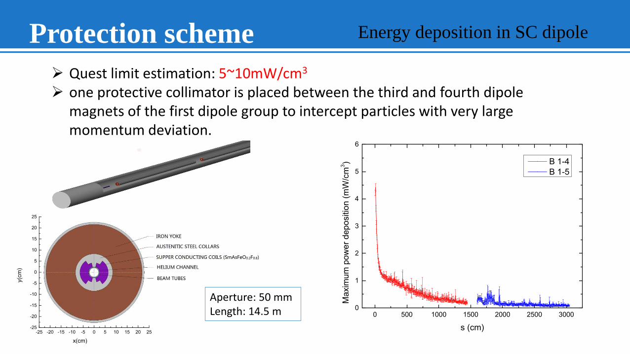
Protection scheme Energy deposition in SC dipole
Quest limit estimation: 5~10mW/cm3
one protective collimator is placed between the third and fourth dipole magnets of the first dipole group to intercept particles with very large momentum deviation.
Aperture: 50 mmLength: 14.5 m
conclusions
• The consecutive collimation method by arranging both transverse and
momentum collimation systems in the same cleaning insertion and
employs superconducting quadrupoles has a good performace. The
goal of collimation inefficiency 3.5510-7 m-1 can be accomplished.
• With protective shieldings, the power deposition in the
superconducting coils in the collimation section can be reduced to
below 10 mW/cm3, which is safe from quenching.

Next to do
• Consider the effect of the imperfections of collimators, like offset errors, tilt errors, flatness errors and so on.
• In LAL, study a combined collimation method used in LHC, HE-LHC, even FCC-hh and SPPC
• Study the background sources from beam-beam interactions and the collimator themselves.
Acknowledgements
• Thanks to A. Faus-Golfe, Yanliang Han and J. Molson for their help
• FCPPL for support internship at LAL


