

Ф PO Box 1777, Dripping Springs, Texas 78620 Phone: 512-380-1988 protection-consultants.com
February 25, 2011 Stala® Integrated Assemblies, LLC 5101 Commerce Crossings Drive, Suite A Louisville, KY 40229 ATTN: Mr. Joe Keith (502) 7794-2104; [email protected] Re: Blast Load Analysis of STALA® IFAs used at Openings in ICF Wall Construction
Protection Engineering Consultants (PEC) Project 10-066 References: Final Report and Design Summary dated February 25, 2011 Dear Joe, Protection Engineering Consultants (PEC) is happy to provide the attached Final Report and Design Summary for our evaluation of STALA® integrated framing assemblies (IFA) used to frame insulating concrete form (ICF) wall openings subjected to blast loads. The analysis and design guidance for ICF walls with STALA® IFAs was performed and developed to support applications where Department of Defense UFC 4-010-01 criteria and where response satisfying low level of protection (LLOP) is required. PEC developed a non-composite resistance function for each ICF wall and STALA® IFA combination for use in the single-degree-of-freedom (SDOF) analysis program SBEDS v4.0. Design tables were constructed for DoD charge weights and standoffs based on the results of the SDOF analyses. The design tables illustrate how the STALA® IFAs improve ICF wall blast performance as a function of opening width and clear spacing. In general, STALA® IFAs improve the performance of the typical ICF wall, such that the all cases analyzed meet the DoD LLOP response criteria when subjected to DoD charge weights at conventional construction standoffs. Please contact us with any questions or comments. Very truly yours, PROTECTION ENGINEERING CONSULTANTS, LLC Texas Firm Registration Number F-9149 Carrie Davis, E.I.T. Senior Associate Engineer Kirk Marchand, P.E. Managing Principal

ko
Final Report for: BLAST LOAD ANALYSIS OF STALA® INTEGRATED FRAMING ASSEMBLIES USED AT OPENINGS IN INSULATED CONCRETE FORM WALL CONSTRUCTION Prepared for: Stala® Integrated Assemblies, LLC 5101 Commerce Crossings Drive, Suite A Louisville, KY 40229 Prepared by: Carrie Davis, E.I.T. Kirk Marchand, P.E. Protection Engineering Consultants PO Box 1777 Dripping Springs, Texas 78620 Project No. 10-066 Texas Firm Registration Number F-9149 February 25, 2011

CONTENTS
1 EXECUTIVE SUMMARY ....................................................................................................................... 1
2 SECTION PROPERTIES: ICF WALL AND STALA® IFA ...................................................................... 2
2.1 STALA® IFA Section Properties ...................................................................................................... 2
2.2 Typical ICF Wall Cross-Section ....................................................................................................... 4
2.3 Typical Wall Opening Geometries ................................................................................................... 4
3 ANALYSIS ASSUMPTIONS AND RESULTS ........................................................................................ 4
3.1 Analysis Overview ............................................................................................................................ 4
3.2 Resistance Functions ....................................................................................................................... 6
3.3 Response Criteria for DoD Facilities ................................................................................................ 8
3.4 SDOF Analysis Results .................................................................................................................... 8
4 DESIGN TABLES FOR DOD FACILITIES .......................................................................................... 11
5 DESIGN EXAMPLE FOR DOD FACILITY ........................................................................................... 12
5.1 Problem Statement ........................................................................................................................ 12
5.2 Solution .......................................................................................................................................... 13
6 CONCLUSIONS AND RECOMMENDATIONS ................................................................................... 14

1
BLAST LOAD ANALYSIS OF STALA® INTEGRATED FRAMING ASSEMBLIES USED AT OPENINGS IN INSULATED CONCRETE FORM WALL CONSTRUCTION
1 EXECUTIVE SUMMARY
Protection Engineering Consultants (PEC) was engaged by Stala® Integrated Assemblies, LLC to
evaluate STALA® integrated framing assemblies (IFA) used to frame insulating concrete form (ICF) wall
openings subjected to blast loads. The main goal was to develop design guidance for ICF walls with
STALA® IFAs for Department of Defense (DoD) loads while meeting the DoD low level of protection
(LLOP) response criteria (UFC 04-010-01). Stala® provided STALA® IFA cross-sections, a typical ICF
wall cross-section, and typical ICF wall geometries to be analyzed. PEC developed a non-composite
resistance function for each ICF wall and STALA® IFA combination for use in single-degree-of-freedom
(SDOF) analysis program, specifically SBEDS v4.0. Design tables were constructed for DoD charge
weights and standoffs based on the results of the SDOF analyses. The design tables illustrate how the
STALA® IFAs impact ICF wall blast performance as a function of opening width and clear spacing. In
general, STALA® IFAs improve the performance of the typical ICF wall, such that the all cases analyzed
meet the DoD LLOP response criteria when subjected to DoD charge weights at conventional
construction standoffs. This report presents a summary of our assumptions, analyses, results, and
recommendations.
Protection Engineering Consultants is a small business that provides research, design and consulting
services to enhance the physical protection of people, systems and the built environment. Working with
government agencies, the design community and industry, we bring expertise in multi-hazard assessment
and protective design to mitigate blast, ballistic and vehicular impact attacks and accidents. Through the
application of established and novel scientific methodologies as well as government and industry best
practices, we help our clients maximize the physical security of plant, property and people while
preserving utility and aesthetics. Our analysis and design capabilities include blast and impact loads
prediction with tools ranging from simple chart based and data fit approaches to computational fluids
dynamics (CFD) calculations. Our mechanical and structural analysis capabilities range from simple
SDOF approaches to high-fidelity LSDYNA modeling and simulation of the large deformation behavior of
structures subjected to shock or impact.

2
2 SECTION PROPERTIES: ICF WALL AND STALA® IFA
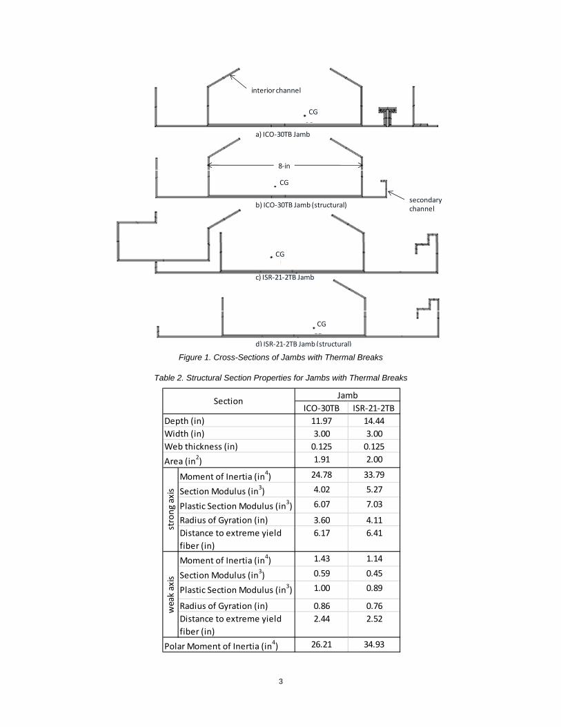
2.1 STALA® IFA Section Properties PEC engineers determined structural properties for STALA® IFAs from geometries provided by
Stala®. Stala® provided two head and jamb types with and without thermal breaks, designated ICO-30
and ISR-21-2. Section properties for each member were determined using ShapeBuilder and are
summarized in Table 1 and Appendix A. In general, all IFAs analyzed were 16 gauge, galvanized steel
(Gr. 50) sections designed for use with an 8-in thick ICF wall system. PEC focused on the jamb sections
with thermal breaks (TB) as recommended by Stala®. This assumption is conservative because jambs
without thermal breaks have more continuous structural steel to support the ICF wall and will have greater
capacity. The thermal break joint is attached with silicone, thus the sections in front of the thermal break
were assumed to be non-structural and were conservatively ignored when calculating section properties
used in the blast analyses, as illustrated in Figure 1. Structural section properties for ICO-30TB and ISR-
21-2TB jambs are summarized in Table 2. The 8-in deep interior channel is connected to the secondary
channel with two parallel spot welds at the webs and two arc welds at flanges, alternating every 6-in.
Calculations assuming 1/4-in spot welds and 1-in long arc welds show a shear capacity of 1 kip/in at this
interface.
Table 1. IFA Section Properties
ICO‐30 ICO‐30TB ICO‐30 ICO‐30TB ISR‐21‐2 ISR‐21‐2TB ISR‐21‐2 ISR‐21‐2TB
14.59 14.59 14.59 14.59 16.38 16.38 16.38 16.38
2.06 2.06 3.00 3.00 3.13 3.13 3.13 3.25
0.125 0.125 0.125 0.125 0.125 0.125 0.125 0.125
1.94 2.26 2.17 2.49 2.32 2.55 2.55 2.78
Moment of Inertia (in4) 35.64 42.07 38.02 44.68 61.64 65.51 64.02 67.99
Section Modulus (in3) 4.99 5.38 5.36 5.79 7.51 7.64 7.84 7.99
Plastic Section Modulus (in3) 7.22 8.55 7.95 9.27 10.38 11.21 11.11 11.94
Radius of Gyration (in) 4.28 4.32 4.18 4.24 5.15 5.07 5.01 4.95
Distance to extreme yield
fiber (in)
7.14 7.82 7.09 7.72 8.20 8.57 8.16 8.51
Moment of Inertia (in4) 0.54 0.58 1.55 1.57 1.57 1.66 2.36 2.52
Section Modulus (in3) 0.31 0.34 0.63 0.64 0.62 0.67 1.00 1.03
Plastic Section Modulus (in3) 0.54 0.71 1.10 1.27 1.26 11.21 1.82 2.07
Radius of Gyration (in) 0.52 0.51 0.84 0.80 0.82 0.81 0.96 0.95
Distance to extreme yield
fiber (in)
1.75 1.71 2.46 2.44 2.54 2.49 2.37 2.45
36.17 42.65 39.57 46.25 63.20 67.17 66.38 70.52
weak axis
Polar Moment of Inertia (in4)
Area (in2)
Web thickness (in)
strong axis
Width (in)
Depth (in)
SectionHead Jamb Head Jamb
3
Figure 1. Cross-Sections of Jambs with Thermal Breaks
Table 2. Structural Section Properties for Jambs with Thermal Breaks
a) ICO‐30TB Jamb
b) ICO‐30TB Jamb (structural)
c) ISR‐21‐2TB Jamb
d) ISR‐21‐2TB Jamb (structural)
interior channel
secondary channel
CG
CG
CG
CG
8‐in
ICO‐30TB ISR‐21‐2TB
11.97 14.44
3.00 3.00
0.125 0.125
1.91 2.00
Moment of Inertia (in4) 24.78 33.79
Section Modulus (in3) 4.02 5.27
Plastic Section Modulus (in3) 6.07 7.03
Radius of Gyration (in) 3.60 4.11
Distance to extreme yield
fiber (in)
6.17 6.41
Moment of Inertia (in4) 1.43 1.14
Section Modulus (in3) 0.59 0.45
Plastic Section Modulus (in3) 1.00 0.89
Radius of Gyration (in) 0.86 0.76
Distance to extreme yield
fiber (in)
2.44 2.52
26.21 34.93
weak axis
Polar Moment of Inertia (in4)
JambSection
Depth (in)
Width (in)
Web thickness (in)
Area (in2)
strong axis
4
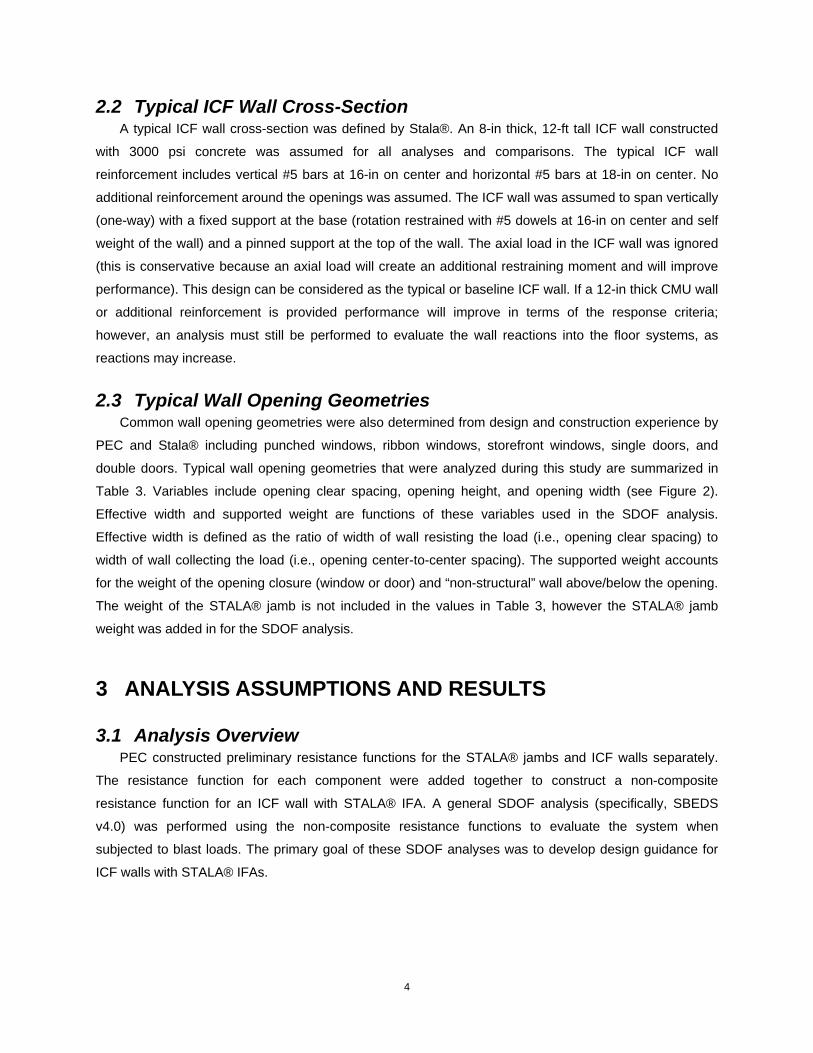
2.2 Typical ICF Wall Cross-Section A typical ICF wall cross-section was defined by Stala®. An 8-in thick, 12-ft tall ICF wall constructed
with 3000 psi concrete was assumed for all analyses and comparisons. The typical ICF wall
reinforcement includes vertical #5 bars at 16-in on center and horizontal #5 bars at 18-in on center. No
additional reinforcement around the openings was assumed. The ICF wall was assumed to span vertically
(one-way) with a fixed support at the base (rotation restrained with #5 dowels at 16-in on center and self
weight of the wall) and a pinned support at the top of the wall. The axial load in the ICF wall was ignored
(this is conservative because an axial load will create an additional restraining moment and will improve
performance). This design can be considered as the typical or baseline ICF wall. If a 12-in thick CMU wall
or additional reinforcement is provided performance will improve in terms of the response criteria;
however, an analysis must still be performed to evaluate the wall reactions into the floor systems, as
reactions may increase.
2.3 Typical Wall Opening Geometries Common wall opening geometries were also determined from design and construction experience by
PEC and Stala® including punched windows, ribbon windows, storefront windows, single doors, and
double doors. Typical wall opening geometries that were analyzed during this study are summarized in
Table 3. Variables include opening clear spacing, opening height, and opening width (see Figure 2).
Effective width and supported weight are functions of these variables used in the SDOF analysis.
Effective width is defined as the ratio of width of wall resisting the load (i.e., opening clear spacing) to
width of wall collecting the load (i.e., opening center-to-center spacing). The supported weight accounts
for the weight of the opening closure (window or door) and “non-structural” wall above/below the opening.
The weight of the STALA® jamb is not included in the values in Table 3, however the STALA® jamb
weight was added in for the SDOF analysis.
3 ANALYSIS ASSUMPTIONS AND RESULTS
3.1 Analysis Overview PEC constructed preliminary resistance functions for the STALA® jambs and ICF walls separately.
The resistance function for each component were added together to construct a non-composite
resistance function for an ICF wall with STALA® IFA. A general SDOF analysis (specifically, SBEDS
v4.0) was performed using the non-composite resistance functions to evaluate the system when
subjected to blast loads. The primary goal of these SDOF analyses was to develop design guidance for
ICF walls with STALA® IFAs.

5
Table 3. Typical Wall Geometries
opening type wall
depth
(in)
wall
height
(ft)
opening
clear
spacing (ft)
opening
height
(ft)
opening
width
(ft)
effective
width
supported
weight
(psf)
punched window 8 12 20 6 4 0.83 54.0
punched window 8 12 10 6 4 0.71 54.0
punched window 8 12 5 6 4 0.56 54.0
punched window 8 12 2 6 4 0.33 54.0
single door 8 12 20 8 3 0.87 38.7
single door 8 12 10 8 3 0.77 38.7
single door 8 12 5 8 3 0.63 38.7
single door 8 12 2 8 3 0.40 38.7
double door 8 12 20 8 6 0.77 38.7
double door 8 12 10 8 6 0.63 38.7
double door 8 12 5 8 6 0.45 38.7
double door 8 12 2 8 6 0.25 38.7
ribbon window 8 12 20 6 12 0.63 54.0
ribbon window 8 12 10 6 12 0.45 54.0
ribbon window 8 12 5 6 12 0.29 54.0
ribbon window 8 12 20 4 20 0.50 69.3
ribbon window 8 12 10 4 20 0.33 69.3
ribbon window 8 12 5 4 20 0.20 69.3
ribbon window 8 12 20 8 20 0.50 38.7
ribbon window 8 12 10 8 20 0.33 38.7
ribbon window 8 12 5 8 20 0.20 38.7
ribbon window 8 12 20 6 30 0.40 54.0
ribbon window 8 12 10 6 30 0.25 54.0
ribbon window 8 12 5 6 30 0.14 54.0
storefront window 8 12 10 10 40 0.20 23.3
storefront window 8 12 5 10 40 0.11 23.3
NOTES:
‐ effective width = opening clear spacing/opening center‐to‐center spacing
‐ opening center‐to‐center spacing = opening clear spacing + 2(opening width/2)
‐ supported weight includes opening closure and wall above/below opening weight,
STALA weight not yet included

6
Figure 2. Schematic of Typical Wall Elevation
3.2 Resistance Functions Individual resistance functions were developed for each STALA® jamb and ICF wall as a function of
opening geometry. A resistance function is a relationship of the member capacity and midspan
displacement (i.e., load vs. displacement). The area under the resistance-displacement curve is
equivalent to the amount of work the member can absorb when subjected to a blast load.
When developing the STALA® jamb resistance function for the SDOF analysis, the following
assumptions were made: the jamb is fully braced by the ICF wall which prevents lateral torsional buckling
of the section and the jamb is simply supported over the full wall height. Also, in accordance with UFC 3-
340-02 the steel yield strength was increased by a dynamic increase factor (DIF) of 1.19 and strength
increase factors (SIF) of 1.05. DIF account for the high strain rates present in blast loading. Materials
subjected to rapidly applied loads, such as blast loads, exhibit an increase in strength under the small
duration load. To account for this increase in strength, material properties are multiplied by dynamic
increase factors (DIF). A SIF is also used to account for the expected strength of a material over the
specified strength. Resistance functions for each type of STALA® jamb are dependent on the opening
clear spacing, as shown in Figure 3. For the same opening clear spacing, the ISR-21-2TB STALA® jamb
has a larger area under the resistance-displacement curve than ICO-30TB.
Development of the ICF wall resistance functions included the following assumptions: 1) one-way
span, 2) fixed-simple boundary conditions, 3) no axial load, and 4) baseline cross-section described in
Section 2.2. Dynamic and strength increase factors (DIF and SIF) were again used to increase the
concrete (by 1.19 and 1.0, respectively) and rebar (by 1.17 and 1.1, respectively) material properties
(UFC 3-340-02). Two-way action of ICF wall above/below openings was ignored and only included as
mass (i.e., non-structural). ICF wall resistance functions for are dependent on the effective width, as
shown in Figure 4. As the effective width increases, the area under the resistance function increases.
opening center‐to‐center spacing
opening clear spacing
opening width
opening
height
wall height
Note: openings include windows and doors

7
Figure 3. Resistance Functions for STALA® Jambs
Figure 4. Resistance Functions for ICF walls
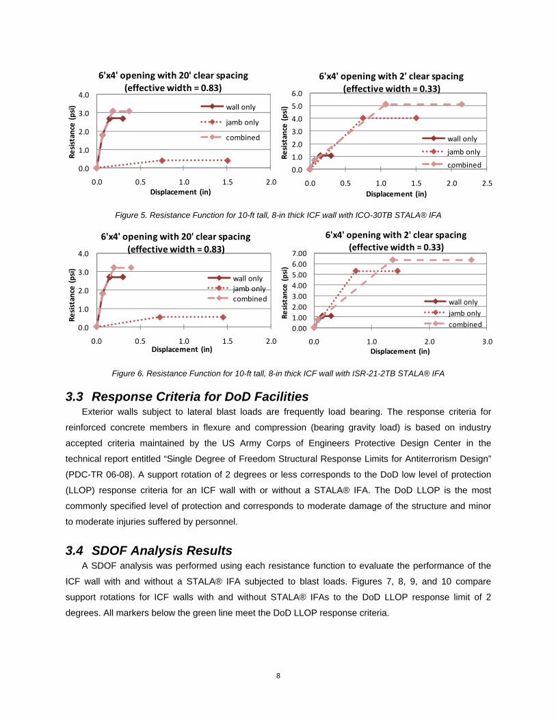
A non-composite resistance function was created for each typical wall geometry combination with
each type of STALA® IFA (a few are shown in Figures 5 and 6). In general, a reinforced concrete wall is
much stiffer than a steel jamb; thus, the stiffness of ICF wall was assumed to control the initial response.
The combined resistance functions initially follow the elastic and elastic-plastic ICF wall stiffness’s. The
ultimate resistance was determined by adding the plastic resistance of the ICF wall and STALA® jamb
(i.e., non-composite action that does not account for the shear transfer between components). Note, that
composite action between the ICF wall and STALA® jamb was evaluated; however, initial calculations did
not show a substantial increase in response over non-composite action. The location of the STALA® IFA
in the overall cross section, which is inherent to the wall geometry, is not ideal to provide additional
bending capacity compositely. Thus, only a non-composite system was assumed, which is the lower
bound of response. Again, the area under the curve is equal to the potential amount of energy the system
can dissipate (i.e., more area under the curve equals better performance of the system).
0.0
0.5
1.0
1.5
2.0
2.5
3.0
3.5
4.0
4.5
0.0 0.5 1.0 1.5 2.0
Resistance (psi)
Displacement (in)
2‐ft opening clear spacing
5‐ft opening clear spacing
10‐ft opening clear spacing
20‐ft opening clear spacing
ICO‐30TB STALA Jamb
0.0
1.0
2.0
3.0
4.0
5.0
6.0
0.0 0.5 1.0 1.5 2.0
Resistance (psi)
Displacement (in)
2‐ft opening clear spacing5‐ft opening clear spacing10‐ft openig clear spacing20‐ft opening clear spacing
ISR‐21‐2TB STALA Jamb
1.00
0.87
0.770.71
0.63
0.50
0.400.33
0.20
0.11
0.0
0.5
1.0
1.5
2.0
2.5
3.0
3.5
0.00 0.05 0.10 0.15 0.20 0.25 0.30 0.35
Resistance (psi)
Displacement (in)
effective width
8
Figure 5. Resistance Function for 10-ft tall, 8-in thick ICF wall with ICO-30TB STALA® IFA
Figure 6. Resistance Function for 10-ft tall, 8-in thick ICF wall with ISR-21-2TB STALA® IFA
3.3 Response Criteria for DoD Facilities Exterior walls subject to lateral blast loads are frequently load bearing. The response criteria for
reinforced concrete members in flexure and compression (bearing gravity load) is based on industry
accepted criteria maintained by the US Army Corps of Engineers Protective Design Center in the
technical report entitled “Single Degree of Freedom Structural Response Limits for Antiterrorism Design”
(PDC-TR 06-08). A support rotation of 2 degrees or less corresponds to the DoD low level of protection
(LLOP) response criteria for an ICF wall with or without a STALA® IFA. The DoD LLOP is the most
commonly specified level of protection and corresponds to moderate damage of the structure and minor
to moderate injuries suffered by personnel.
3.4 SDOF Analysis Results A SDOF analysis was performed using each resistance function to evaluate the performance of the
ICF wall with and without a STALA® IFA subjected to blast loads. Figures 7, 8, 9, and 10 compare
support rotations for ICF walls with and without STALA® IFAs to the DoD LLOP response limit of 2
degrees. All markers below the green line meet the DoD LLOP response criteria.
0.0
1.0
2.0
3.0
4.0
0.0 0.5 1.0 1.5 2.0
Resistance (psi)
Displacement (in)
6'x4' opening with 20' clear spacing (effective width = 0.83)
wall only
jamb only
combined
0.0
1.0
2.0
3.0
4.0
5.0
6.0
0.0 0.5 1.0 1.5 2.0 2.5
Resistance (psi)
Displacement (in)
6'x4' opening with 2' clear spacing
(effective width = 0.33)
wall only
jamb only
combined
0.0
1.0
2.0
3.0
4.0
0.0 0.5 1.0 1.5 2.0
Resistance (psi)
Displacement (in)
6'x4' opening with 20' clear spacing
(effective width = 0.83)
wall onlyjamb onlycombined
0.00
1.00
2.00
3.00
4.00
5.00
6.00
7.00
0.0 1.0 2.0 3.0
Resistance (psi)
Displacement (in)
6'x4' opening with 2' clear spacing (effective width = 0.33)
wall only
jamb only
combined

9
Figure 7. SDOF Analysis Results for 10-ft tall, 8-in thick ICF wall with ICO-30TB STALA® IFA for DoD Charge Weights at Conventional Construction Standoffs (UFC 4-010-01)
Figure 8. SDOF Analysis Results for 10-ft tall, 8-in thick ICF wall with ICO-30TB STALA® IFA for DoD Charge Weights at Minimum Standoffs (UFC 4-010-01)
0
1
2
3
4
5
6
7
0.0 0.2 0.4 0.6 0.8 1.0
Rotation (d
eg)
effective width
DoD LLOP Response Limit
ICF wall only CWI @ 148ft
ICF wall only CWII @ 82ft
ICF wall with STALA® CWI @ 148‐ft
ICF wall with STALA® CWII @ 82‐ft
0
2
4
6
8
10
12
14
16
0.0 0.2 0.4 0.6 0.8 1.0
Rotation (d
eg)
effective width
DoD LLOP Response Limit
ICF wall only CWI @ 82‐ft
ICF wall only CWII @ 33ft
ICF wall with STALA® CWI @ 82‐ft
ICF wall with STALA® CWII @ 33‐ft

10
Figure 9. SDOF Analysis Results for 10-ft tall, 8-in thick ICF wall with ISR-21-2TB STALA® IFA for DoD Charge Weights at Conventional Construction Standoffs (UFC 4-010-01)
Figure 10. SDOF Analysis Results for 10-ft tall, 8-in thick ICF wall with ISR-21-2TB STALA® IFA for DoD Charge Weights at Minimum Standoffs (UFC 4-010-01)
0
1
2
3
4
5
6
7
0.0 0.2 0.4 0.6 0.8 1.0
Rotation (deg)
effective width
DoD LLOP Response Limit
ICF wall only CWI @ 148ft
ICF wall only CWII @ 82ft
ICF wall with STALA® CWI @ 148‐ft
ICF wall with STALA® CWII @ 82‐ft
0
2
4
6
8
10
12
14
16
0.0 0.2 0.4 0.6 0.8 1.0
Rotation (d
eg)
effective width
DoD LLOP Response Limit
ICF wall only CWI@ 82‐ft
ICF wall only CWII @ 33ft
ICF wall with STALA® CWI @ 82‐ft
ICF wall with STALA® CWII @ 33‐ft

11
4 DESIGN TABLES FOR DOD FACILITIES
The Department of Defense (DoD) developed the Unified Facilities Criteria 4-010-01, “DoD Minimum
Anti-Terrorism Standards Buildings” to specify required minimum antiterrorism standards for new and
existing DoD buildings. The following tables illustrate allowable ICF wall opening width and opening clear
spacing combinations that meet the DoD LLOP response criteria when subjected to DoD minimum loads
(CWI or CWII) at various standoffs. The green areas highlight opening width and opening clear spacing
combinations at which an ICF wall with STALA® IFA satisfies DoD LLOP (for the design assumptions
stated in Section 2.2). The red areas highlight combinations at which the ICF wall with STALA® IFA will
require additional wall reinforcement to meet the DoD LLOP criteria, and the gray areas indicate
combinations at which the ICF wall with STALA® IFA meets the DoD LLOP; however the STALA® IFA is
not required for strength (the ICF wall alone would be sufficient).
Table 4. Design Tables for 10-ft tall, 8-in thick ICF wall with ICO-30TB STALA® IFA for DoD Billeting, High Occupancy Family Housing, and Primary Gathering Buildings (UFC 4-010-01 – Low Level of Protection - LLOP)
Note: design tables are based on typical wall cross-section and geometry described in Section 2.2
2 5 10 20 2 5 10 20
40
30
20
12
6
4
3
2 5 10 20 2 5 10 20
40
30
20
12
6
4
3Opening Width (ft)
Design Table for
DoD Conventional
Construction
Opening Width (ft)
Design Table for
DoD Minimum
Standoffs
Opening Clear Spacing (ft)
DoD CWI at 148‐ft DoD CWII at 82‐ft
Opening Clear Spacing (ft)
DoD CWI at 82‐ft DoD CWII at 33‐ft
KEY:
= ICF wall with STALA® IFA does not meet DoD LLOP = ICF wall without STALA® IFA meets DoD LLOP
= ICF wall with STALA® IFA meets DoD LLOP = not typical construction

12
Table 5. Design Tables for 10-ft tall, 8-in thick ICF wall with ISR-21-2TB STALA® IFA for DoD Billeting, High Occupancy Family Housing, and Primary Gathering Buildings (UFC 4-010-01 – Low Level of Protection - LLOP)
Note: design tables are based on typical wall cross-section and geometry described in Section 2.2
5 DESIGN EXAMPLE FOR DOD FACILITY
To illustrate the use of the above design tables shown above, an example from a typical DoD project
is provided below.
5.1 Problem Statement Determine if the DoD barracks façade, illustrated in Figure 11, composed of an ICF wall with windows
framed with ISR-21-2-TB STALA® IFA, meets the DoD low level of protection criteria (LLOP) for the DoD
loads charge weight I (CWI) and CWII at:
a) Conventional construction standoffs (i.e., structure is within a controlled perimeter that is 148-
ft away and has a standoff of 82-ft from all parking lots and roadways).
b) Minimum standoffs (i.e., structure is within a controlled perimeter that is 82-ft away and has a
standoff of 33-ft from all parking lots and roadways).
2 5 10 20 2 5 10 20
40
30
20
12
6
4
3
2 5 10 20 2 5 10 20
40
30
20
12
6
4
3Opening Width (ft)
Opening Clear Spacing (ft)
DoD CWI at 148‐ft DoD CWII at 82‐ft
Design Table for
DoD Conventional
Construction
Opening Clear Spacing (ft)
DoD CWI at 82‐ft DoD CWII at 33‐ft
Design Table for
DoD Minimum
Standoffs
Opening Width (ft)
KEY:
= ICF wall with STALA® IFA does not meet DoD LLOP = ICF wall without STALA® IFA meets DoD LLOP
= ICF wall with STALA® IFA meets DoD LLOP = not typical construction

13
Figure 11. Design Example Problem Statement
5.2 Solution Design assumptions based on the project elevations and floor plans are summarized in Figure 11.
The baseline ICF wall design of an 8-in thick, around 12-ft tall, 3000 psi concrete wall with #5 rebar at 16-
in on center horizontally and vertically was assumed. The typical window (or opening) width is 4’-8” and
the typical window (or opening) clear spacing is 2’-8”. These two variables are then used in the proper
design tables to determine if the ICF wall with STALA® IFA meets the DoD LLOP response criteria. For
DoD conventional construction standoffs (part A), the ICF wall with STALA® IFA meets the DoD LLOP
criteria for CWI and CWII and no additional steel is required to support the window frame, as shown in
Table 6. The combination falls within a gray area, which means that the ICF wall without STALA® IFA
would also meet the DoD LLOP response criteria. For DoD minimum standoffs (part B), the ICF wall with
STALA® IFA also meets the DoD LLOP criteria for CWI and CWII and no additional steel is required to
support the window frame, as shown in Table 7. In this case, the combinations fall within a green area
which signifies that the STALA® IFA is needed to meet the DoD LLOP criteria.
Design Assumptions:
• Wall design: 8‐in thick, 3000 psi, #5 rebar at 16‐in O.C. vertically and horizontally
• Wall height: ~ 12‐ft
• Opening clear spacing = 2’‐8”
• Opening width = 4’‐8”
Plan ViewElevation
Opening width
Window spacing

14
Table 6. Solution to Part A
Table 7. Solution to Part B
6 CONCLUSIONS AND RECOMMENDATIONS
Design and application tables for performance of ICF walls with STALA® IFA subjected to blast loads
were developed based on the results of SDOF analyses performed by PEC. In general, the ISR-21-2TB
STALA® jamb performs better than the ICO-30TB STALA® jamb due to the increased area under the
resistance-displacement curve; however both STALA® jambs improve the system response over the ICF
wall alone. STALA® IFAs improve the performance of an ICF wall the most when a narrow segment of
wall is provided between openings. All ICF wall cases with STALA® IFAs analyzed for DoD loads at the
conventional construction standoffs meet the DoD LLOP response criteria. For DoD loads at minimum
standoffs, additional reinforcement or supporting IFAs will be needed (and will typically be provided) to
meet the DoD LLOP for opening widths greater than 40-ft. The provided design tables illustrate how the
2 5 10 20 2 5 10 20
40
30
20
12
6
4
3Opening Width (ft)
Opening Clear Spacing (ft)
DoD CWI at 148‐ft DoD CWII at 82‐ft
Design Table for
DoD Conventional
Construction
KEY:
= ICF wall with STALA IFA does not meet DoD LLOP = ICF wall without STALA IFA meets DoD LLOP
= ICF wall with STALA IFA meets DoD LLOP = not typical construction
Reference: UFC 04‐010‐01
KEY:
= ICF wall with STALA IFA does not meet DoD LLOP = ICF wall without STALA IFA meets DoD LLOP
= ICF wall with STALA IFA meets DoD LLOP = not typical construction
2 5 10 20 2 5 10 20
40
30
20
12
6
4
3
Opening Clear Spacing (ft)
DoD CWI at 82‐ft DoD CWII at 33‐ft
Design Table for
DoD Minimum
Standoffs
Opening Width (ft)
Reference: UFC 04‐010‐01

15
STALA® IFAs improve ICF wall blast performance as a function of opening width and spacing. If the ICF
wall properties, blast loads, or level of protection are significantly different than the values assumed in this
report, a qualified structural engineer should be consulted for guidance associated with the ICF wall and
STALA® IFA system. Overall, ICF walls with STALA® IFAs at openings improve ICF wall performance
when subjected to blast loads, in addition to improving energy efficiency and speed of construction.
Future work could include static testing of an ICF wall with STALA® IFA to validate the assumed
resistance functions and anchorage into concrete. This would determine the level of conservatism present
based on the assumption of non-composite resistance functions in the analysis presented here.

ko
Design Summary for: DESIGN TABLES FOR STALA® IFA USED AT OPENINGS IN ICF WALL CONSTRUCTION SUBJECTED TO BLAST LOADS Prepared for: STALA® Integrated Assemblies, LLC 5101 Commerce Crossings Drive, Suite A Louisville, KY 40229 Prepared by: Carrie Davis, E.I.T. Kirk Marchand, P.E. Protection Engineering Consultants PO Box 1777 Dripping Springs, Texas 78620 Project No. 10-066 Texas Firm Registration Number F-9149 February 25, 2011

1
DESIGN TABLES FOR STALA® IFA USED AT OPENINGS IN ICF WALL CONSTRUCTION SUBJECTED TO BLAST LOADS
Protection Engineering Consultants (PEC) was engaged by Stala® Integrated Assemblies, LLC to
evaluate STALA® integrated framing assemblies (IFA) used to frame insulating concrete form (ICF) wall
openings subjected to blast loads. PEC developed a non-composite resistance function for each ICF wall
and STALA® IFA combination for use in single-degree-of-freedom (SDOF) analysis program, specifically
SBEDS v4.0, to evaluate the system.
The Department of Defense (DoD) developed the Unified Facilities Criteria 4-010-01, “DoD Minimum
Anti-Terrorism Standards Buildings” to specify required minimum antiterrorism standards for new and
existing DoD buildings. The following design tables illustrate how STALA® IFAs improve ICF wall
performance subjected to blast loads as a function of opening width and opening clear spacing while
meeting the DoD low level of protection (LLOP) response criteria (PDC-TR 06-08). Common wall
openings include punched windows, ribbon windows, storefront windows, single doors, and double doors.
The green areas highlight opening width and clear spacing combinations at which an ICF wall with
STALA® IFA satisfies the DoD LLOP. The red areas highlight combinations at which the ICF wall with
STALA® IFA will require additional reinforcement to meet the DoD LLOP criteria, and the gray areas
indicate combinations at which the ICF wall with STALA® IFA satisfies the DoD LLOP (the ICF wall alone
is sufficient).
The baseline ICF wall design includes: 8-in thick, 12-ft span, 3000 psi concrete, #5 bars at 16-in on
center vertically, and #5 bars at 18-in on center horizontally. ICO-30TB and ISR-21-2TB jambs are 16
gauge, galvanized steel (Gr. 50) sections designed for use in an 8-in thick ICF wall system. The portion of
jamb in front of the thermal break was assumed to be non-structural.
Overall, ICF walls with STALA® IFAs at openings improve ICF wall performance when subjected to
blast loads, in addition to improving energy efficiency and speed of construction. If the ICF wall design,
blast load, or LOP are significantly different than the values assumed in the design tables, please consult
a qualified structural engineer for guidance associated with the system.
Figure 1. Schematic of Typical Wall Elevation
opening center‐to‐center spacing
opening clear spacing
opening width
opening
height
wall height
Note: openings include windows and doors

2
Figure 2. Cross-Sections of ICO-30TB STALA® Jamb
Table 1. Design Tables for 10-ft tall, 8-in thick ICF wall with ICO-30TB STALA® IFA for DoD Billeting, High Occupancy Family Housing, and Primary Gathering Buildings (UFC 4-010-01 – Low Level of Protection - LLOP)
Note: design tables are based on baseline ICF wall design
a) ICO‐30TB Jamb
b) ICO‐30TB Jamb (structural)
CG
CG
8‐in
2 5 10 20 2 5 10 20
40
30
20
12
6
4
3
2 5 10 20 2 5 10 20
40
30
20
12
6
4
3Opening Width (ft)
Design Table for
DoD Conventional
Construction
Opening Width (ft)
Design Table for
DoD Minimum
Standoffs
Opening Clear Spacing (ft)
DoD CWI at 148‐ft DoD CWII at 82‐ft
Opening Clear Spacing (ft)
DoD CWI at 82‐ft DoD CWII at 33‐ft
KEY:
= ICF wall with STALA® IFA does not meet DoD LLOP = ICF wall without STALA® IFA meets DoD LLOP
= ICF wall with STALA® IFA meets DoD LLOP = not typical construction

3
Figure 3. Cross-Sections of ISR-2-21TB STALA® Jamb
Table 2. Design Tables for 10-ft tall, 8-in thick ICF wall with ISR-2-21TB STALA® IFA for DoD Billeting, High Occupancy Family Housing, and Primary Gathering Buildings (UFC 4-010-01 – Low Level of Protection - LLOP)
Note: design tables are based on baseline ICF wall design
a) ISR‐21‐2TB Jamb
b) ISR‐21‐2TB Jamb (structural)
CG
CG
8‐in
2 5 10 20 2 5 10 20
40
30
20
12
6
4
3
2 5 10 20 2 5 10 20
40
30
20
12
6
4
3Opening Width (ft)
Opening Clear Spacing (ft)
DoD CWI at 148‐ft DoD CWII at 82‐ft
Design Table for
DoD Conventional
Construction
Opening Clear Spacing (ft)
DoD CWI at 82‐ft DoD CWII at 33‐ft
Design Table for
DoD Minimum
Standoffs
Opening Width (ft)
KEY:
= ICF wall with STALA® IFA does not meet DoD LLOP = ICF wall without STALA® IFA meets DoD LLOP
= ICF wall with STALA® IFA meets DoD LLOP = not typical construction


