

Strain-induced modulation of perpendicular magnetic anisotropy in Ta/CoFeB/MgOstructures investigated by ferromagnetic resonanceGuoqiang Yu, Zhenxing Wang, Maryam Abolfath-Beygi, Congli He, Xiang Li, Kin L. Wong, Paul Nordeen, HaoWu, Gregory P. Carman, Xiufeng Han, Ibrahim A. Alhomoudi, Pedram Khalili Amiri, and Kang L. Wang Citation: Applied Physics Letters 106, 072402 (2015); doi: 10.1063/1.4907677 View online: http://dx.doi.org/10.1063/1.4907677 View Table of Contents: http://scitation.aip.org/content/aip/journal/apl/106/7?ver=pdfcov Published by the AIP Publishing Articles you may be interested in Influence of boron diffusion on the perpendicular magnetic anisotropy in Ta|CoFeB|MgO ultrathin films J. Appl. Phys. 117, 043913 (2015); 10.1063/1.4906096 Opposite signs of voltage-induced perpendicular magnetic anisotropy change in CoFeB|MgO junctions withdifferent underlayers Appl. Phys. Lett. 103, 082410 (2013); 10.1063/1.4819199 Enhanced interface perpendicular magnetic anisotropy in Ta|CoFeB|MgO using nitrogen doped Ta underlayers Appl. Phys. Lett. 102, 242405 (2013); 10.1063/1.4811269 Perpendicular-anisotropy CoFeB-MgO magnetic tunnel junctions with a MgO/CoFeB/Ta/CoFeB/MgO recordingstructure Appl. Phys. Lett. 101, 022414 (2012); 10.1063/1.4736727 Current-induced effective field in perpendicularly magnetized Ta/CoFeB/MgO wire Appl. Phys. Lett. 98, 142505 (2011); 10.1063/1.3579155
This article is copyrighted as indicated in the article. Reuse of AIP content is subject to the terms at: http://scitation.aip.org/termsconditions. Downloaded to IP:
128.97.89.222 On: Tue, 24 Feb 2015 21:35:52

Strain-induced modulation of perpendicular magnetic anisotropyin Ta/CoFeB/MgO structures investigated by ferromagnetic resonance
Guoqiang Yu,1 Zhenxing Wang,1,2 Maryam Abolfath-Beygi,1 Congli He,1 Xiang Li,1
Kin L. Wong,1 Paul Nordeen,3 Hao Wu,4 Gregory P. Carman,3 Xiufeng Han,4
Ibrahim A. Alhomoudi,6 Pedram Khalili Amiri,1,5 and Kang L. Wang1
1Department of Electrical Engineering, University of California, Los Angeles, California 90095, USA2Wuhan National High Magnetic Field Center, Huazhong University of Science and Technology,Wuhan 430074, China3Department of Mechanical and Aerospace Engineering, University of California, Los Angeles,California 90095, USA4Beijing National Laboratory of Condensed Matter Physics, Institute of Physics, Chinese Academy of Sciences,Beijing 100190, China5Inston Inc., Los Angeles, California 90095, USA6National Nanotechnology Research Center, King Abdulaziz City for Science and Technology, Riyadh 11442,Saudi Arabia
(Received 7 December 2014; accepted 27 January 2015; published online 17 February 2015)
We demonstrate strain-induced modulation of perpendicular magnetic anisotropy (PMA) in (001)-
oriented [Pb(Mg1/3Nb2/3)O3](1�x)-[PbTiO3]x (PMN-PT) substrate/Ta/CoFeB/MgO/Ta structures
using ferromagnetic resonance (FMR). An in-plane biaxial strain is produced by applying voltage
between the two surfaces of the PMN-PT substrate, and is transferred to the ferromagnetic CoFeB
layer, which results in tuning of the PMA of the CoFeB layer. The strain-induced change in PMA
is quantitatively extracted from the experimental FMR spectra. It is shown that both first and
second-order anisotropy terms are affected by the electric field, and that they have opposite voltage
dependencies. A very large value of the voltage-induced perpendicular magnetic anisotropy modu-
lation of �7000 fJ/V�m is obtained through this strain-mediated coupling. Using this FMR tech-
nique, the magnetostriction coefficient k is extracted for the ultrathin 1.1 nm Co20Fe60B20 layer,
and is found to be 3.7� 10�5, which is approximately 4 times larger than the previously reported
values for CoFeB films thicker than 5 nm. In addition, the effect of strain on the effective damping
constant (aeff) is also studied and no obvious modulation of the aeff is observed. The results are rel-
evant to the development of CoFeB-MgO magnetic tunnel junctions for memory applications.VC 2015 AIP Publishing LLC. [http://dx.doi.org/10.1063/1.4907677]
Manipulation of magnetization by electric currents and
voltages has attracted enormous research interest in the spin-
tronics community, due to its applications in magnetic logic
devices and magnetic random access memory (MRAM).1 In
particular, the current-induced spin transfer torque (STT)2–4
has been extensively studied for magnetization switching in
spintronic devices. However, the high energy dissipation and
density limitation due to the large critical current are still chal-
lenging for practical applications. Recently, manipulation of
magnetization by electric field in ferromagnetic/ferroelectric
(FM/FE) heterostructures has attracted considerable atten-
tion,5–18 as a pathway towards lower dynamic energy dissipa-
tion. A particular ferroelectric crystal material [Pb(Mg1/3Nb2/
3)O3]1�x–[PbTiO3]x (PMN-PT), which exhibits a large piezo-
electric effect, is often used in FM/FE heterostructures. In this
type of heterostructure, strain or charge induced by an electric
field applied on the PMN-PT layer is capable of manipulating
the magnetic anisotropy of the adjacent magnetic layer, result-
ing in a magnetoelectric effect. Experiments have demonstrated
that strain can produce reversible and permanent magnetic ani-
sotropy reorientation, as well as generate and control magneto-
static surface spin waves.14,16,19–21 The study of FM/FE
heterostructures has also resulted in the recently proposed appli-
cation in strain-transfer torque random access memory.22
In terms of the memory density, scaling behavior, and
thermal stability, perpendicularly magnetized ferromagnets
are more promising for applications at scaled technology
nodes than their in-plane magnetized counterparts.23,24 As a
result, techniques enabling the manipulation of perpendicular
magnetic anisotropy (PMA) in magnetic materials are highly
desired for memory applications. There have been a number
of experiments studying the manipulation of PMA through
voltage-induced strain in different material systems, such as
CoxPd1�x alloys,10 L10-FePt,8,9 [Co/Pd]n/CoFeB multi-
layers,11 CoPt,13 and FePd.12 However, the strain-mediated
modulation of PMA in typical MgO-based magnetic tunnel
junction (MTJ) materials (i.e., Ta/CoFeB/MgO structures)
has not yet been studied in detail, while it is needed to allow
for data readout using tunnel magnetoresistance (TMR) in
MTJs in practical applications. On the other hand, while
charge-mediated modulation of anisotropy has been widely
studied and used for switching in MTJs,25–34 the sensitivity
of PMA to changes in electric field reported in those cases is
significantly smaller than what can be expected in a strain-
mediated mechanism. In addition, recent studies have shown
that strain modulation may play a role in the observed volt-
age control of magnetic anisotropy (VCMA) effect in these
MTJ material stacks as well.35
Here, we have studied the influence of voltage-induced
strain on the PMA in ultrathin 1.1 nm CoFeB layer through fer-
romagnetic resonance (FMR) measurements. The experimental
results show that the PMA of an ultrathin 1.1 nm CoFeB layer
0003-6951/2015/106(7)/072402/5/$30.00 VC 2015 AIP Publishing LLC106, 072402-1
APPLIED PHYSICS LETTERS 106, 072402 (2015)
This article is copyrighted as indicated in the article. Reuse of AIP content is subject to the terms at: http://scitation.aip.org/termsconditions. Downloaded to IP:
128.97.89.222 On: Tue, 24 Feb 2015 21:35:52

can be modulated by voltage-induced strain and results in a
very large PMA modulation of up to �7000 fJ/V�m. In addi-
tion, the magnetostriction coefficient of the ultrathin 1.1 nm
CoFeB layer is extracted from these measurements, and is
observed to be larger than reported values in 5 nm thick
CoFeB film. The dependence of the effective damping con-
stant as a function of strain is also studied, showing no signifi-
cant strain dependence in the range of applied voltages in our
experiment.
The sample structure studied in this experiment was
PMN-PT (001 crystal orientation)/Ta (8)/Co20Fe60B20
(CoFeB) (1.1)/MgO (2)/Ta (2), where thickness values are
given in nanometers. The (001) orientated PMN-PT crystal
substrate of 0.5 mm thickness is used to generate in-plane
biaxial strain when voltage is applied between its top and
down surfaces due to its piezoelectric property. The other
layers were deposited at room temperature in an AJA
International Physical Vapor Deposition System with base
pressure of less than 2� 10�8 Torr. The metallic layers were
grown by DC-sputtering. The MgO layer was grown by
RF-sputtering from an MgO target. The sample was subse-
quently annealed at 250 �C for 30 min to improve crystallin-
ity and enhance PMA. The sample was characterized by a
vibrating sample magnetometer (VSM) to determine the sat-
uration magnetization (Ms) and obtain magnetic hysteresis
loops. The FMR measurements were carried out on a Bruker
EPR spectrometer using a microwave cavity with frequency
of 9.5 GHz. The sample was mounted on a locally made
probe with electrical wires for applying voltage. The sample
holder also allows for changing the angle between the film
normal direction and the direction of the applied magnetic
field. The FMR spectrum, i.e., the field derivatives of the
absorbed power, was measured by a lock-in technique, where
the applied modulated ac magnetic field is 10 Oe in the FMR
measurement. The measured sample had a 2 mm� 2 mm
square shape. The electric field was applied across the PMN-
PT as shown in Fig. 1(a). The applied maximum voltage in
this experiment is 200 V, corresponding to an electric-field
strength E of 0.4 MV/m. All the measurements were carried
out at room temperature.
Figure 1(b) shows the normalized magnetization as a
function of in-plane and out-of-plane magnetic fields. The
two loops exhibit a similar saturation magnetic field, which
indicates a perpendicular magnetic anisotropy nearly cancel-
ling the shape-induced demagnetization field. The value of
Ms is determined to be 1250 emu/cm3. The field derivatives
of the absorbed power are shown in Fig. 1(c) for different
applied magnetic field angles (hH), defined as the angle
between the magnetic field and the normal direction of the
sample plain. Based on the FMR spectra, the resonance field
HR (approximated as the center field between the positive and
negative peak fields) and the peak-to-peak line-width DH can
be extracted for different hH values, as will be discussed later.
To study the strain-induced change of PMA in the
CoFeB layer, the FMR spectra were measured with different
voltages applied to the PMN-PT substrate, as shown in Figs.
2(a)–2(c). Figure 2(a) shows the HR dependence on the elec-
tric field for hH¼ 10�. The FMR spectra are shown in Fig.
2(b), which correspond to the black curve in Fig. 2(a). A
similar modulation of HR has also been observed in other
material systems.18,36–38 The curve for a full sweep of the
electric field is a typical butterfly-shaped loop, corresponding
to the electric-field-induced strain in the PMN-PT substrate.
For hH¼ 10�, the value of HR is shifted to a lower field by
FIG. 1. (a) Schematic of the sample structure and the measurement configu-
ration. (b) In-plane (red solid circles) and out-of-plane (blue open squares)
magnetic hysteresis loops of the samples for zero electric field. (c) FMR
spectrum as a function of external magnetic field for different magnetic field
angles (hH).
FIG. 2. (a) Strain-induced modulation of the FMR field (HR) by an electric
field applied across the PMN-PT substrate for hH¼ 10�. Measured FMR
spectra for electric field values of E¼ 0, 0.2, and 0.4 MV/m at hH¼ 10� (b)
and 70� (c), which correspond to black curve in Fig. 2(a), i.e., sweeping
electric field from the positive maximum.
072402-2 Yu et al. Appl. Phys. Lett. 106, 072402 (2015)
This article is copyrighted as indicated in the article. Reuse of AIP content is subject to the terms at: http://scitation.aip.org/termsconditions. Downloaded to IP:
128.97.89.222 On: Tue, 24 Feb 2015 21:35:52
positive electric fields. However, for hH¼ 70�, HR is shifted
to a higher magnetic field.
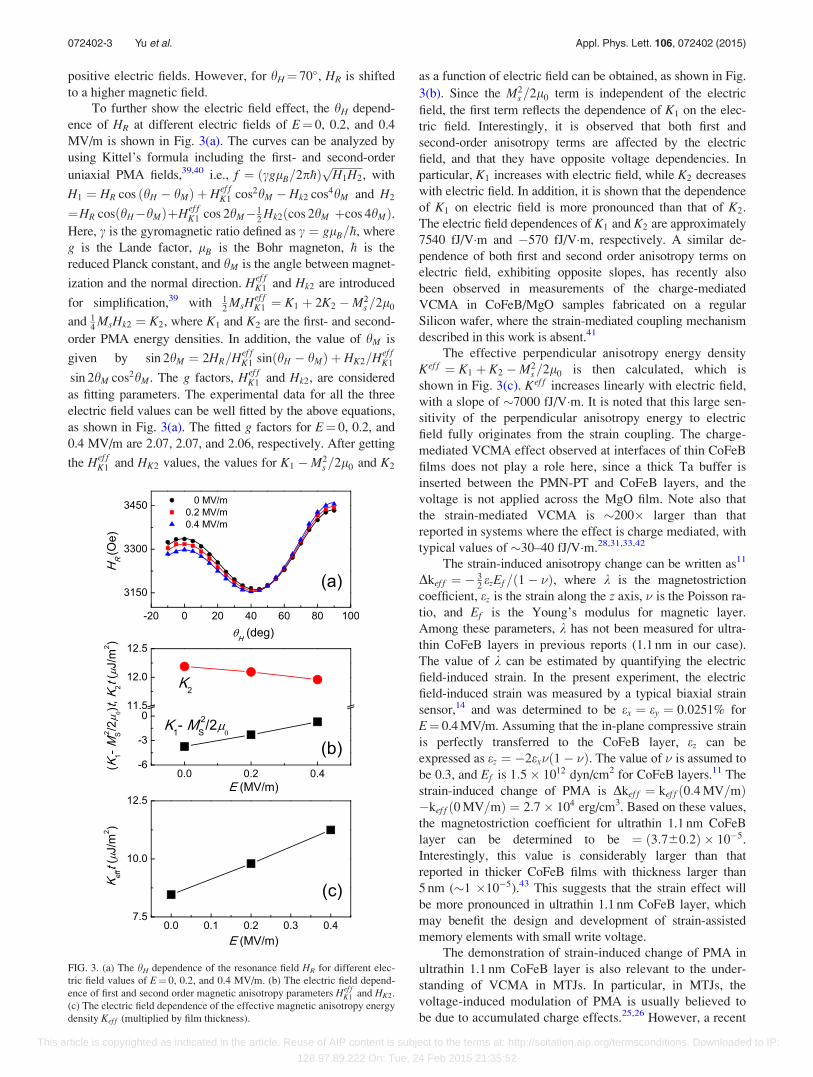
To further show the electric field effect, the hH depend-
ence of HR at different electric fields of E¼ 0, 0.2, and 0.4
MV/m is shown in Fig. 3(a). The curves can be analyzed by
using Kittel’s formula including the first- and second-order
uniaxial PMA fields,39,40 i.e., f ¼ ðcglB=2p�hÞffiffiffiffiffiffiffiffiffiffiffi
H1H2
p, with
H1 ¼ HR cos ðhH � hMÞ þ Hef fK1 cos2hM � Hk2 cos4hM and H2
¼HR cos hH�hMð ÞþHef fK1 cos 2hM�1
2Hk2ðcos 2hM þcos 4hMÞ.
Here, c is the gyromagnetic ratio defined as c ¼ glB=�h, where
g is the Lande factor, lB is the Bohr magneton, �h is the
reduced Planck constant, and hM is the angle between magnet-
ization and the normal direction. Hef fK1 and Hk2 are introduced
for simplification,39 with 12
MsHef fK1 ¼ K1 þ 2K2 �M2
s =2l0
and 14
MsHk2 ¼ K2, where K1 and K2 are the first- and second-
order PMA energy densities. In addition, the value of hM is
given by sin 2hM ¼ 2HR=Hef fK1 sinðhH � hMÞ þ HK2=Hef f
K1
sin 2hM cos2hM. The g factors, Hef fK1 and Hk2, are considered
as fitting parameters. The experimental data for all the three
electric field values can be well fitted by the above equations,
as shown in Fig. 3(a). The fitted g factors for E¼ 0, 0.2, and
0.4 MV/m are 2.07, 2.07, and 2.06, respectively. After getting
the Hef fK1 and HK2 values, the values for K1 �M2
s =2l0 and K2
as a function of electric field can be obtained, as shown in Fig.
3(b). Since the M2s =2l0 term is independent of the electric
field, the first term reflects the dependence of K1 on the elec-
tric field. Interestingly, it is observed that both first and
second-order anisotropy terms are affected by the electric
field, and that they have opposite voltage dependencies. In
particular, K1 increases with electric field, while K2 decreases
with electric field. In addition, it is shown that the dependence
of K1 on electric field is more pronounced than that of K2.
The electric field dependences of K1 and K2 are approximately
7540 fJ/V�m and �570 fJ/V�m, respectively. A similar de-
pendence of both first and second order anisotropy terms on
electric field, exhibiting opposite slopes, has recently also
been observed in measurements of the charge-mediated
VCMA in CoFeB/MgO samples fabricated on a regular
Silicon wafer, where the strain-mediated coupling mechanism
described in this work is absent.41
The effective perpendicular anisotropy energy density
Kef f ¼ K1 þ K2 �M2s =2l0 is then calculated, which is
shown in Fig. 3(c). Kef f increases linearly with electric field,
with a slope of �7000 fJ/V�m. It is noted that this large sen-
sitivity of the perpendicular anisotropy energy to electric
field fully originates from the strain coupling. The charge-
mediated VCMA effect observed at interfaces of thin CoFeB
films does not play a role here, since a thick Ta buffer is
inserted between the PMN-PT and CoFeB layers, and the
voltage is not applied across the MgO film. Note also that
the strain-mediated VCMA is �200� larger than that
reported in systems where the effect is charge mediated, with
typical values of �30–40 fJ/V�m.28,31,33,42
The strain-induced anisotropy change can be written as11
Dkef f ¼ � 32ezEf=ð1� �Þ, where k is the magnetostriction
coefficient, ez is the strain along the z axis, � is the Poisson ra-
tio, and Ef is the Young’s modulus for magnetic layer.
Among these parameters, k has not been measured for ultra-
thin CoFeB layers in previous reports (1.1 nm in our case).
The value of k can be estimated by quantifying the electric
field-induced strain. In the present experiment, the electric
field-induced strain was measured by a typical biaxial strain
sensor,14 and was determined to be ex ¼ ey ¼ 0:0251% for
E¼ 0.4 MV/m. Assuming that the in-plane compressive strain
is perfectly transferred to the CoFeB layer, ez can be
expressed as ez ¼ �2ex�ð1� �Þ. The value of � is assumed to
be 0.3, and Ef is 1:5� 1012 dyn/cm2 for CoFeB layers.11 The
strain-induced change of PMA is Dkef f ¼ kef f ð0:4 MV=mÞ�kef f ð0 MV=mÞ ¼ 2:7� 104 erg/cm3. Based on these values,
the magnetostriction coefficient for ultrathin 1.1 nm CoFeB
layer can be determined to be ¼ ð3:760:2Þ � 10�5.
Interestingly, this value is considerably larger than that
reported in thicker CoFeB films with thickness larger than
5 nm (�1 �10�5).43 This suggests that the strain effect will
be more pronounced in ultrathin 1.1 nm CoFeB layer, which
may benefit the design and development of strain-assisted
memory elements with small write voltage.
The demonstration of strain-induced change of PMA in
ultrathin 1.1 nm CoFeB layer is also relevant to the under-
standing of VCMA in MTJs. In particular, in MTJs, the
voltage-induced modulation of PMA is usually believed to
be due to accumulated charge effects.25,26 However, a recent
FIG. 3. (a) The hH dependence of the resonance field HR for different elec-
tric field values of E¼ 0, 0.2, and 0.4 MV/m. (b) The electric field depend-
ence of first and second order magnetic anisotropy parameters Hef fK1 and HK2.
(c) The electric field dependence of the effective magnetic anisotropy energy
density Kef f (multiplied by film thickness).
072402-3 Yu et al. Appl. Phys. Lett. 106, 072402 (2015)
This article is copyrighted as indicated in the article. Reuse of AIP content is subject to the terms at: http://scitation.aip.org/termsconditions. Downloaded to IP:
128.97.89.222 On: Tue, 24 Feb 2015 21:35:52
experiment has indicated that a voltage applied across the
MgO barrier can also generate strain in MgO due to its pie-
zoelectric effect.35 This strain can be transferred to the adja-
cent CoFeB layer, hence supplementing the charge-mediated
change of anisotropy. In particular, it is interesting to com-
pare the voltage-induced strain in the PMN-PT and MgO
cases. The strain (ez) response to the electric field in MgO is
calculated to be �3.7� 10�5 ppm per V/m, based on the data
in Ref. 35. By comparison, the ez value is determined to be
�1.25� 10�3 ppm per V/m in PMN-PT, i.e., �33� larger
than in MgO. Hence, the voltage-induced strain on the ultra-
thin CoFeB layer in MgO-based MTJs, although �33�smaller in the case of MgO compared to PMN-PT, may also
contribute to the modulation of PMA.
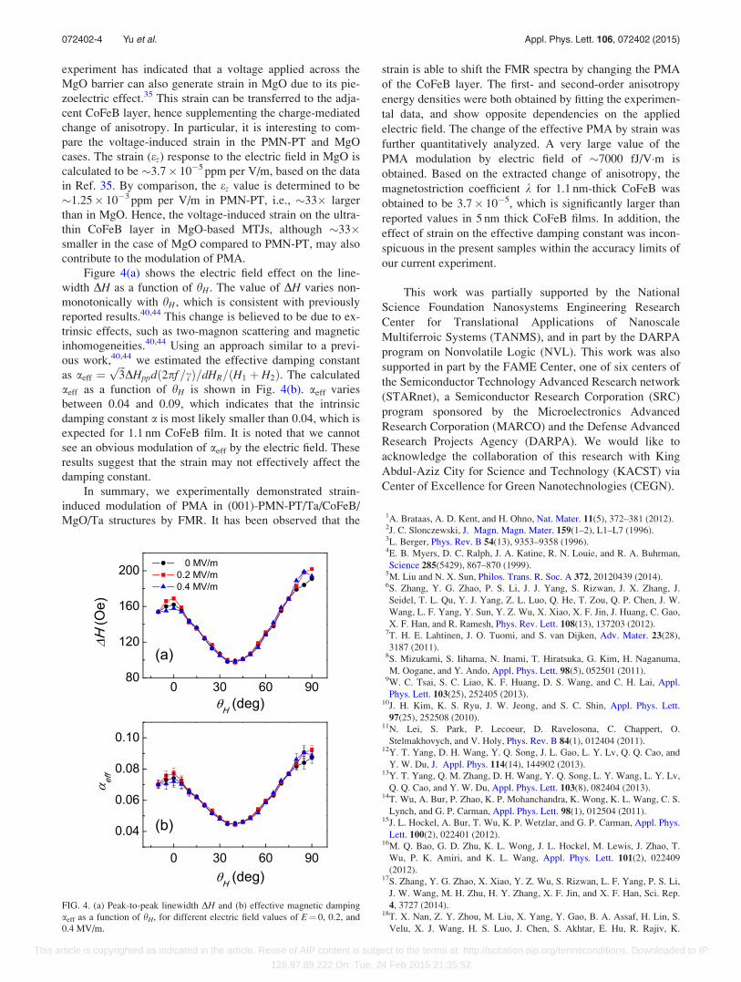
Figure 4(a) shows the electric field effect on the line-
width DH as a function of hH. The value of DH varies non-
monotonically with hH, which is consistent with previously
reported results.40,44 This change is believed to be due to ex-
trinsic effects, such as two-magnon scattering and magnetic
inhomogeneities.40,44 Using an approach similar to a previ-
ous work,40,44 we estimated the effective damping constant
as aeff ¼ffiffiffi
3p
DHppdð2pf=cÞ=dHR=ðH1 þ H2Þ. The calculated
aeff as a function of hH is shown in Fig. 4(b). aeff varies
between 0.04 and 0.09, which indicates that the intrinsic
damping constant a is most likely smaller than 0.04, which is
expected for 1.1 nm CoFeB film. It is noted that we cannot
see an obvious modulation of aeff by the electric field. These
results suggest that the strain may not effectively affect the
damping constant.
In summary, we experimentally demonstrated strain-
induced modulation of PMA in (001)-PMN-PT/Ta/CoFeB/
MgO/Ta structures by FMR. It has been observed that the
strain is able to shift the FMR spectra by changing the PMA
of the CoFeB layer. The first- and second-order anisotropy
energy densities were both obtained by fitting the experimen-
tal data, and show opposite dependencies on the applied
electric field. The change of the effective PMA by strain was
further quantitatively analyzed. A very large value of the
PMA modulation by electric field of �7000 fJ/V�m is
obtained. Based on the extracted change of anisotropy, the
magnetostriction coefficient k for 1.1 nm-thick CoFeB was
obtained to be 3.7� 10�5, which is significantly larger than
reported values in 5 nm thick CoFeB films. In addition, the
effect of strain on the effective damping constant was incon-
spicuous in the present samples within the accuracy limits of
our current experiment.
This work was partially supported by the National
Science Foundation Nanosystems Engineering Research
Center for Translational Applications of Nanoscale
Multiferroic Systems (TANMS), and in part by the DARPA
program on Nonvolatile Logic (NVL). This work was also
supported in part by the FAME Center, one of six centers of
the Semiconductor Technology Advanced Research network
(STARnet), a Semiconductor Research Corporation (SRC)
program sponsored by the Microelectronics Advanced
Research Corporation (MARCO) and the Defense Advanced
Research Projects Agency (DARPA). We would like to
acknowledge the collaboration of this research with King
Abdul-Aziz City for Science and Technology (KACST) via
Center of Excellence for Green Nanotechnologies (CEGN).
1A. Brataas, A. D. Kent, and H. Ohno, Nat. Mater. 11(5), 372–381 (2012).2J. C. Slonczewski, J. Magn. Magn. Mater. 159(1–2), L1–L7 (1996).3L. Berger, Phys. Rev. B 54(13), 9353–9358 (1996).4E. B. Myers, D. C. Ralph, J. A. Katine, R. N. Louie, and R. A. Buhrman,
Science 285(5429), 867–870 (1999).5M. Liu and N. X. Sun, Philos. Trans. R. Soc. A 372, 20120439 (2014).6S. Zhang, Y. G. Zhao, P. S. Li, J. J. Yang, S. Rizwan, J. X. Zhang, J.
Seidel, T. L. Qu, Y. J. Yang, Z. L. Luo, Q. He, T. Zou, Q. P. Chen, J. W.
Wang, L. F. Yang, Y. Sun, Y. Z. Wu, X. Xiao, X. F. Jin, J. Huang, C. Gao,
X. F. Han, and R. Ramesh, Phys. Rev. Lett. 108(13), 137203 (2012).7T. H. E. Lahtinen, J. O. Tuomi, and S. van Dijken, Adv. Mater. 23(28),
3187 (2011).8S. Mizukami, S. Iihama, N. Inami, T. Hiratsuka, G. Kim, H. Naganuma,
M. Oogane, and Y. Ando, Appl. Phys. Lett. 98(5), 052501 (2011).9W. C. Tsai, S. C. Liao, K. F. Huang, D. S. Wang, and C. H. Lai, Appl.
Phys. Lett. 103(25), 252405 (2013).10J. H. Kim, K. S. Ryu, J. W. Jeong, and S. C. Shin, Appl. Phys. Lett.
97(25), 252508 (2010).11N. Lei, S. Park, P. Lecoeur, D. Ravelosona, C. Chappert, O.
Stelmakhovych, and V. Holy, Phys. Rev. B 84(1), 012404 (2011).12Y. T. Yang, D. H. Wang, Y. Q. Song, J. L. Gao, L. Y. Lv, Q. Q. Cao, and
Y. W. Du, J. Appl. Phys. 114(14), 144902 (2013).13Y. T. Yang, Q. M. Zhang, D. H. Wang, Y. Q. Song, L. Y. Wang, L. Y. Lv,
Q. Q. Cao, and Y. W. Du, Appl. Phys. Lett. 103(8), 082404 (2013).14T. Wu, A. Bur, P. Zhao, K. P. Mohanchandra, K. Wong, K. L. Wang, C. S.
Lynch, and G. P. Carman, Appl. Phys. Lett. 98(1), 012504 (2011).15J. L. Hockel, A. Bur, T. Wu, K. P. Wetzlar, and G. P. Carman, Appl. Phys.
Lett. 100(2), 022401 (2012).16M. Q. Bao, G. D. Zhu, K. L. Wong, J. L. Hockel, M. Lewis, J. Zhao, T.
Wu, P. K. Amiri, and K. L. Wang, Appl. Phys. Lett. 101(2), 022409
(2012).17S. Zhang, Y. G. Zhao, X. Xiao, Y. Z. Wu, S. Rizwan, L. F. Yang, P. S. Li,
J. W. Wang, M. H. Zhu, H. Y. Zhang, X. F. Jin, and X. F. Han, Sci. Rep.
4, 3727 (2014).18T. X. Nan, Z. Y. Zhou, M. Liu, X. Yang, Y. Gao, B. A. Assaf, H. Lin, S.
Velu, X. J. Wang, H. S. Luo, J. Chen, S. Akhtar, E. Hu, R. Rajiv, K.
FIG. 4. (a) Peak-to-peak linewidth DH and (b) effective magnetic damping
aeff as a function of hH, for different electric field values of E¼ 0, 0.2, and
0.4 MV/m.
072402-4 Yu et al. Appl. Phys. Lett. 106, 072402 (2015)
This article is copyrighted as indicated in the article. Reuse of AIP content is subject to the terms at: http://scitation.aip.org/termsconditions. Downloaded to IP:
128.97.89.222 On: Tue, 24 Feb 2015 21:35:52

Krishnan, S. Sreedhar, D. Heiman, B. M. Howe, G. J. Brown, and N. X.
Sun, Sci. Rep. 4, 3688 (2014).19T. Wu, A. Bur, K. Wong, P. Zhao, C. S. Lynch, P. K. Amiri, K. L. Wang,
and G. P. Carman, Appl. Phys. Lett. 98(26), 262504 (2011).20P. S. Li, A. T. Chen, D. L. Li, Y. G. Zhao, S. Zhang, L. F. Yang, Y. Liu,
M. H. Zhu, H. Y. Zhang, and X. F. Han, Adv. Mater. 26(25), 4320–4325
(2014).21S. Cherepov, P. K. Amiri, J. G. Alzate, K. Wong, M. Lewis, P.
Upadhyaya, J. Nath, M. Q. Bao, A. Bur, T. Wu, G. P. Carman, A. Khitun,
and K. L. Wang, Appl. Phys. Lett. 104(8), 082403 (2014).22A. Khan, D. E. Nikonov, S. Manipatruni, T. Ghani, and I. A. Young, Appl.
Phys. Lett. 104(26), 262407 (2014).23S. Ikeda, K. Miura, H. Yamamoto, K. Mizunuma, H. D. Gan, M. Endo, S.
Kanai, J. Hayakawa, F. Matsukura, and H. Ohno, Nat. Mater. 9(9),
721–724 (2010).24P. K. Amiri, Z. M. Zeng, J. Langer, H. Zhao, G. Rowlands, Y. J. Chen, I.
N. Krivorotov, J. P. Wang, H. W. Jiang, J. A. Katine, Y. Huai, K. Galatsis,
and K. L. Wang, Appl. Phys. Lett. 98(11), 112507 (2011).25M. Weisheit, Science 315(5815), 349 (2007).26T. Maruyama, Y. Shiota, T. Nozaki, K. Ohta, N. Toda, M. Mizuguchi, A.
A. Tulapurkar, T. Shinjo, M. Shiraishi, S. Mizukami, Y. Ando, and Y.
Suzuki, Nat. Nanotechnol. 4(3), 158–161 (2009).27M. K. Niranjan, C. G. Duan, S. S. Jaswal, and E. Y. Tsymbal, Appl. Phys.
Lett. 96(22), 222504 (2010).28M. Endo, S. Kanai, S. Ikeda, F. Matsukura, and H. Ohno, Appl. Phys. Lett.
96(21), 212503 (2010).29P. K. Amiri and K. L. Wang, SPIN 2, 1240002 (2012).30J. G. Alzate, P. K. Amiri, G. Q. Yu, P. Upadhyaya, J. A. Katine, J. Langer,
B. Ocker, I. N. Krivorotov, and K. L. Wang, Appl. Phys. Lett. 104(11),
112401 (2014).
31S. Kanai, M. Yamanouchi, S. Ikeda, Y. Nakatani, F. Matsukura, and H.
Ohno, Appl. Phys. Lett. 101(12), 122403 (2012).32J. G. Alzate, P. K. Amiri, P. Upadhyaya, S. S. Cherepov, J. Zhu, M.
Lewis, R. Dorrance, J. A. Katine, J. Langer, K. Galatsis, D. Markovic, I.
Krivorotov, and K. L. Wang, Tech. Dig. - Int. Electron Devices Meet.
2012, 29.5.1.33W. G. Wang, M. G. Li, S. Hageman, and C. L. Chien, Nat. Mater. 11(1),
64–68 (2011).34Y. Shiota, T. Nozaki, F. Bonell, S. Murakami, T. Shinjo, and Y. Suzuki,
Nat. Mater. 11(1), 39–43 (2011).35V. B. Naik, H. Meng, J. X. Xiao, R. S. Liu, A. Kumar, K. Y. Zeng, P. Luo,
and S. Yap, Appl. Phys. Lett. 105(5), 052403 (2014).36Y. K. Fetisov and G. Srinivasan, Appl. Phys. Lett. 93(3), 033508 (2008).37Y. J. Chen, A. Yang, M. R. Paudel, S. Stadler, C. Vittoria, and V. G.
Harris, Phys. Rev. B 83(10), 104406 (2011).38N. N. Phuoc and C. K. Ong, Appl. Phys. Lett. 105(2), 032901 (2014).39A. Okada, S. Kanai, M. Yamanouchi, S. Ikeda, F. Matsukura, and H.
Ohno, Appl. Phys. Lett. 105(5), 052415 (2014).40S. Iihama, Q. L. Ma, T. Kubota, S. Mizukami, Y. Ando, and T. Miyazaki,
Appl. Phys. Express 5(8), 083001 (2012).41J. G. Alzate, P. K. Amiri, P. Upadhyaya, S. S. Cherepov, J. Zhu, J. A. Katine,
J. Langer, B. Ocker, I. N. Krivorotov, and K. L. Wang, Book of digests ofIEEE International Magnetics Conference (IEEE, 2014), p. AH-10.
42J. Zhu, J. A. Katine, G. E. Rowlands, Y. J. Chen, Z. Duan, J. G. Alzate, P.
Upadhyaya, J. Langer, P. K. Amiri, K. L. Wang, and I. N. Krivorotov,
Phys. Rev. Lett. 108(19), 197203 (2012).43S. U. Jen, Y. D. Yao, Y. T. Chen, J. M. Wu, C. C. Lee, T. L. Tsai, and Y.
C. Chang, J. Appl. Phys. 99(5), 053701 (2006).44X. Chen, K. Wang, Z. Wu, S. Jiang, G. Yang, Y. Liu, J. Teng, and G. Yu,
Appl. Phys. Lett. 105, 092402 (2014).
072402-5 Yu et al. Appl. Phys. Lett. 106, 072402 (2015)
This article is copyrighted as indicated in the article. Reuse of AIP content is subject to the terms at: http://scitation.aip.org/termsconditions. Downloaded to IP:
128.97.89.222 On: Tue, 24 Feb 2015 21:35:52


