
SUB-STATION TEST EQUIPMENT
guidebook
Vanguard Instruments Company, Inc.Reliability through instrumentation
2 0 1 4
condensed edition
5th Edition, August 5th, 2013
Table of ContentsTransformer Turns Ratio TestersProduct Description PageATRT-01 S3 single-phase, ac-powered transformer turns ratio tester 3ATRT-01B S3 single-phase, ac or battery-powered transformer turns ratio tester 3CVT-765 capacitor voltage transformer tester 3ATRT-03 three-phase, ac-powered transformer turns ratio tester with built-in thermal printer 4ATRT-03 S2 three-phase, ac-powered transformer turns ratio tester with built-in thermal printer, usb pc interface, and usb flash drive port 4ATRT-03A S2 three-phase, ac or battery-powered turns ratio tester with built-in thermal printer, usb pc interface, and usb flash drive port 4Tri-Phase true three-phase transformer turns ratio tester with built-in printer, usb pc interface, and usb flash drive port 5
Current Transformer TestersProduct Description PageEZCT-10 current transformer test set (10 amperes) 5EZCT-2000C Plus current transformer test set (2,000 vac) with insulation and burden calculation capabilities and bluetooth interface 5
Micro-OhmmetersProduct Description PageAuto-Ohm 200 S3 10 to 200 amp true dc micro-ohmmeter with usb flash drive port 6DMOM-200 S3 10 to 200 amp true dc micro-ohmmeter with usb flash drive port and built-in thermal printer 6DMOM-600 10 to 600 amp true dc micro-ohmmeter with usb flash drive port and built-in thermal printer 6
Transformer Winding Resistance MetersProduct Description PageWRM-10P 10 amp, two channel, winding resistance meter with built-in thermal printer 7LTCA-10 10 amp, three channel, winding resistance meter with load tap changer contact analyzer, usb pc interface, and usb flash drive port 7LTCA-40 40 amp, three channel, winding resistance meter with load tap changer contact analyzer, usb pc interface, and usb flash drive port 7TRM-20/40 20 amp and 40 amp transformer resistance meters with auto-demagnitization capability 8TRM-203/403 20 amp and 40 amp 3-phase transformer resistance meter with auto-demagnitization capability and no need for cable switching 8TSB perform resistance tests with the trm-203/403 and turns ratio tests with an atrt-03 without making trips to swap cables 9
Circuit Breaker AnalyzersProduct Description PageMCCB-250 250 amp molded case circuit breaker tester 10CT-3500 S2 3-channel time/cycle timer with built-in thermal printer, usb pc interface, and usb flash drive port 10DigiTMR S2 circuit breaker analyzer with three contact inputs, built-in thermal printer, usb pc interface, and usb flash drive port 10DigiTMR S2 PC pc-controlled circuit breaker analyzer with three contact inputs 11CT-7000 S3 circuit breaker analyzer with 3, or 6 contact inputs and extensive storage capability 11CT-8000 S3 circuit breaker analyzer with 3 or 6 contacts, storage capability, first trip capability, and dynamic contact resistance testing capability 11UPS S2 portable ac/dc power supply 12Transducers & Adapters transducers and transducer adapters compatible with Vanguard circuit breaker analyzers 14
Insulation Resistance MetersProduct Description PageIRM-5000P 5 kv insulation resistance meter with built-in thermal printer 12
Relay Test EquipmentProduct Description PageRFD-200 S3 portable relay test set 8PCI-600 600 amp primary current injection source 9
Vacuum Bottle TestersProduct Description PageVBT-60 10 to 60 kv dc vacuum bottle tester 12
2

ATRT-01 S3 Single Phase Transformer Turns Ratio Tester
tran
sfor
mer
tur
ns r
atio
tes
ters
3
specificationsdescription
input power 120Vac or 240Vac (Selectable), 50/60Hz
measurement method ANSI/IEEE C57.12.90
ratio measuring range 0.8 to 15,000 (5-digit Resolution)
turns-ratio accuracy 40 Vac: 0.8–1999(±0.1%), 2,000–3,999 (±0.25%), 4,000–15,000 (±1%) 4 Vac: 0.8–1999(±0.1%), 2,000–3,999 (±0.25%), 4,000–15,000 (±2%)
test voltages 4Vac @ 1.0A, 40Vac @ 0.6A
current reading range 0-2 A, Accuracy: 2% of reading (±1 mA)
display Back-lit LCD Screen (128 x 64 pixels), viewable in bright sunlight and low-light levels
computer interface RS-232C, USB Flash drive port
pc software Windows XP/Vista/7 software is included with purchase price
ATRT-01B S3 Single Phase Transformer Turns Ratio Testerspecificationsdescription
input power 90-240Vac, 50/60 Hz; SLA battery delivers up to 4 hours operation
measurement method ANSI/IEEE C57.12.90
ratio measuring range 0.8 to 15,000 (5-digit Resolution)
turns-ratio accuracy 40 Vac: 0.8–1999(±0.1%), 2,000–3,999 (±0.25%), 4,000–15,000 (±1%) 4 Vac: 0.8–1999(±0.1%), 2,000–3,999 (±0.25%), 4,000–15,000 (±2%)
test voltages 4Vac @ 500mA, 40Vac @ 70mA
current reading range 0-2 A, Accuracy: 2% of reading (±1 mA)
display Back-lit LCD Screen (128 x 64 pixels), viewable in bright sunlight and low-light levels
computer interface RS-232C, USB Flash drive port
pc software Windows XP/Vista/7 software is included with purchase price
CVT-765 Capacitor Voltage Transformer Testerspecificationsdescription
input power 100 – 120 Vac or 220 – 240 Vac (selectable), 50/60 Hz
measurement method ANSI/IEEE C57.12.90
ratio measuring range 75 to 15,000 (5-digit Resolution)
turns-ratio accuracy 75 – 4,999: ±0.1%, 5,000 – 9,999: ±0.2%, 10,000 – 15,000: ±0.5%
test voltages 7440Vac @ 50mA
phase angle reading 0 – 360 degrees (±0.1 degree accuracy)
display Back-lit LCD Screen (128 x 64 pixels), viewable in bright sunlight and low-light levels
computer interface RS-232C, USB Flash drive port
pc software Windows XP/Vista/7 software is included with purchase price
All specifications herein are valid at nominal voltage and ambient temperature of +25°C (+77°F). Specifications are subject to change without notice.
All Vanguard products are designed to meet UL 61010A-1 Certification and CAN/CSA C22.2 No. 1010.1-92 Certification.
The Vanguard ATRT-01 S3 is Vanguard’s fourth generation, microprocessor-based, single phase, automatic transformer turns-ratio tester.
The ATRT-01 S3 uses the IEEE C57.12.90 measuring method to determine the transformer turns-ratio. It is capable of measuring turns ratios from 0.8 to 15,000 and can be used to test voltage regulators, power transformers, current transformers, and potential transformers.
The ATRT-01B S3 is a single-phase, automatic, transformer turns ratio tester with all the features of the ATRT-01 S3 above.
It is powered by a 6-Volt, 7 Ampere-hour, lead-acid battery. The high capacity battery, coupled with the ATRT-01B S3’s low power consuming circuitry, allows the unit to be used continuously for up to 4 hours between re-charges. A built-in charger lets the unit be used while the battery is being charged.
The CVT-765 is a microprocessor-based, single phase, automatic, transformer turns-ratio tester spe-cifically designed to measure the turns-ratios of Capacitor Voltage Transformers (CVT’s).
The CVT-765 determines the turns-ratio using the IEEE C57.12.90 mea-suring method. It uses a 7500Vac excitation voltage source to accurately measure the turns-ratio of Capacitor Voltage Transformers with a rating of up to 765KV.
part number 9023-UC
part number 9036-UC
part number 9025-UC
tran
sfor
mer
tur
ns r
atio
tes
ters
4
ATRT-03 Three Phase Transformer Turns Ratio Testerspecificationsdescription
input power 3 amps, 100-120Vac or 200-240Vac (selectable), 50/60 Hz
measurement method ANSI/IEEE C57.12.90
ratio measuring range 0.8 to 15,000 (5-digit Resolution)
turns-ratio accuracy 0.8 to 1999: ±0.1%, 2000 to 3999: ±0.15%,4,000 to 15,000: ±1% @ 100Vac
test voltages 8 Vac @ 1 Amp, 40 Vac @ 0.6 Amp, 100 Vac @ 0.1 Amp
display Back-lit LCD Screen (4 lines by 20 characters), viewable in bright sunlight and low-light levels
printer 4.5-inch Wide Thermal Printer
computer interface RS-232C
pc software Windows XP/Vista/7 software is included with purchase price
data storage capacity Stores 200 records and 128 test plans
All specifications herein are valid at nominal voltage and ambient temperature of +25°C (+77°F). Specifications are subject to change without notice.
All Vanguard products are designed to meet UL 61010A-1 Certification and CAN/CSA C22.2 No. 1010.1-92 Certification.
ATRT-03 S2 Three Phase Transformer Turns Ratio Testerspecificationsdescription
operating voltage 100-240 Vac, 50/60 Hz
measurement method ANSI/IEEE C57.12.90
ratio measuring range 0.8 to 15,000
turns-ratio accuracy 0.8 to 1999: ±0.1%, 2000 to 3999: ±0.15%, 4,000 to 15,000: ±1% @ 100 Vac
test voltages 8 Vac @ 1 Amp, 40 Vac @ 0.2 Amp, 100 Vac @ 0.1 Amp
display Back-lit LCD, 64 x 128 dot graphic display, Viewable in Bright Sunlight
printer Optional 4.5-inch Wide Thermal Printer
computer interfaces 1 USB Flash Drive Port, 1 RS-232C and 1 USB Interface port
pc software Windows XP/Vista/7 software is included with purchase price
data storage capacity Stores 112 transformer test records and 128 transformer test plans. 999 transformer test records can be stored on a USB Flash Drive.
load tap changer controller Built-in LTC controller
ATRT-03A S2 Three Phase Transformer Turns Ratio Testerspecificationsdescription
operating voltages 100-240 Vac, 50/60 Hz or 12 Vdc
batteries Two lead acid batteries (12V, 2 AH) for up to 3 hours of operation
measurement method ANSI/IEEE C57.12.90
ratio measuring range 0.8 to 15,000
turns-ratio accuracy 0.8 to 1999: ±0.1%, 2000 to 3999: ±0.15%, 4,000 to 15,000: ±1% @ 100 Vac
test voltages 8 Vac @ 350 mA, 40 Vac @ 70 mA, 100 Vac @ 20 mA
display Back-lit LCD, 64 x 128 dot graphic display, Viewable in Bright Sunlight
printer 4.5-inch Wide Thermal Printer
computer interfaces 1 USB Flash Drive Port, 1 RS-232C and 1 USB Interface port
pc software Windows XP/Vista/7 software is included with purchase price
data storage capacity Stores 112 transformer test records and 128 transformer test plans. 999 transformer test records can be stored on a USB Flash Drive.
load tap changer controller Built-in LTC controller
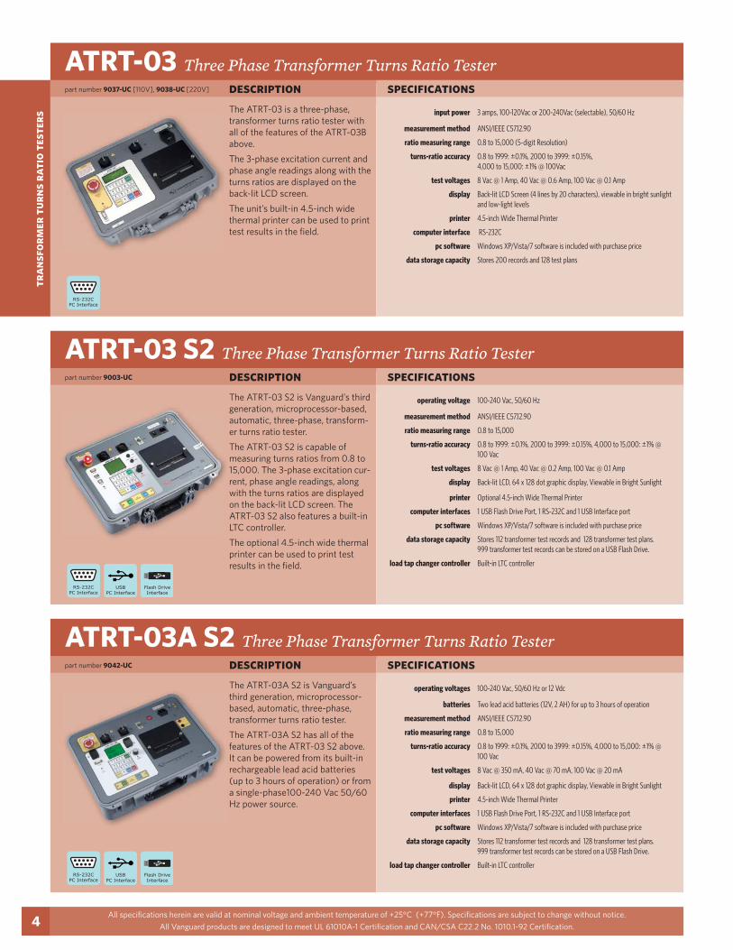
The ATRT-03 is a three-phase, transformer turns ratio tester with all of the features of the ATRT-03B above.
The 3-phase excitation current and phase angle readings along with the turns ratios are displayed on the back-lit LCD screen.
The unit’s built-in 4.5-inch wide thermal printer can be used to print test results in the field.
The ATRT-03 S2 is Vanguard’s third generation, microprocessor-based, automatic, three-phase, transform-er turns ratio tester.
The ATRT-03 S2 is capable of measuring turns ratios from 0.8 to 15,000. The 3-phase excitation cur-rent, phase angle readings, along with the turns ratios are displayed on the back-lit LCD screen. The ATRT-03 S2 also features a built-in LTC controller.
The optional 4.5-inch wide thermal printer can be used to print test results in the field.
The ATRT-03A S2 is Vanguard’s third generation, microprocessor-based, automatic, three-phase, transformer turns ratio tester.
The ATRT-03A S2 has all of the features of the ATRT-03 S2 above. It can be powered from its built-in rechargeable lead acid batteries (up to 3 hours of operation) or from a single-phase100-240 Vac 50/60 Hz power source.
part number 9037-UC [110V], 9038-UC [220V]
part number 9003-UC
part number 9042-UC
tran
sfor
mer
tur
ns r
atio
tes
ters
Tri-Phase True Three Phase Transformer Turns Ratio Testerspecificationsdescription
input power 3 amps, 100-240 Vac, 50/60 Hz
measurement method ANSI/IEEE C57.12.90
ratio measuring range 0.8 to 15,000 (5-digit Resolution)
turns-ratio accuracy 0.8 to 999: ±0.1%, 1000 to 1599: ±0.2%,1600 to 9999: ±1%, 10,000 to 15,000: ±1.5% @ 100 Vac
test voltages Three-phase, 8 Vac @ 1 Amp, 40 Vac @ 0.2 Amp, 100 Vac @ 0.1 Amp
display Back-lit LCD, 64 x 128 dot graphic display, Viewable in Bright Sunlight
printer 4.5-inch Wide Thermal Printer
computer interfaces 1 USB Flash Drive Port, 1 RS-232C and 1 USB Interface port
pc software Windows XP/Vista/7 software is included with purchase price
data storage capacity Stores 112 transformer test records and 128 transformer test plans. 999 transformer test records can be stored on a USB Flash Drive.
load tap changer controller Built-in LTC controller
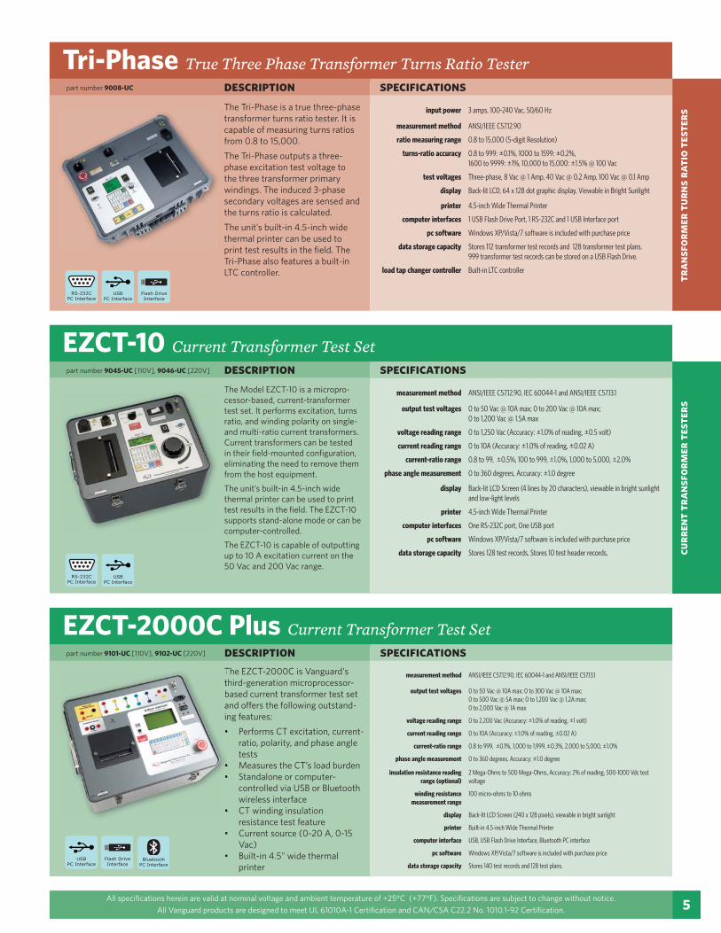
The Tri-Phase is a true three-phase transformer turns ratio tester. It is capable of measuring turns ratios from 0.8 to 15,000.
The Tri-Phase outputs a three-phase excitation test voltage to the three transformer primary windings. The induced 3-phase secondary voltages are sensed and the turns ratio is calculated.
The unit’s built-in 4.5-inch wide thermal printer can be used to print test results in the field. The Tri-Phase also features a built-in LTC controller.
5All specifications herein are valid at nominal voltage and ambient temperature of +25°C (+77°F). Specifications are subject to change without notice.
All Vanguard products are designed to meet UL 61010A-1 Certification and CAN/CSA C22.2 No. 1010.1-92 Certification.
curr
ent
tran
sfor
mer
tes
ters
EZCT-10 Current Transformer Test Setspecificationsdescription
measurement method ANSI/IEEE C57.12.90, IEC 60044-1 and ANSI/IEEE C57.13.1
output test voltages 0 to 50 Vac @ 10A max; 0 to 200 Vac @ 10A max;0 to 1,200 Vac @ 1.5A max
voltage reading range 0 to 1,250 Vac (Accuracy: ±1.0% of reading, ±0.5 volt)
current reading range 0 to 10A (Accuracy: ±1.0% of reading, ±0.02 A)
current-ratio range 0.8 to 99, ±0.5%, 100 to 999, ±1.0%, 1,000 to 5,000, ±2.0%
phase angle measurement 0 to 360 degrees, Accuracy: ±1.0 degree
display Back-lit LCD Screen (4 lines by 20 characters), viewable in bright sunlight and low-light levels
printer 4.5-inch Wide Thermal Printer
computer interfaces One RS-232C port, One USB port
pc software Windows XP/Vista/7 software is included with purchase price
data storage capacity Stores 128 test records. Stores 10 test header records.
EZCT-2000C Plus Current Transformer Test Setspecificationsdescription
The Model EZCT-10 is a micropro-cessor-based, current-transformer test set. It performs excitation, turns ratio, and winding polarity on single- and multi-ratio current transformers. Current transformers can be tested in their field-mounted configuration, eliminating the need to remove them from the host equipment.
The unit’s built-in 4.5-inch wide thermal printer can be used to print test results in the field. The EZCT-10 supports stand-alone mode or can be computer-controlled.
The EZCT-10 is capable of outputting up to 10 A excitation current on the 50 Vac and 200 Vac range.
The EZCT-2000C is Vanguard's third-generation microprocessor-based current transformer test set and offers the following outstand-ing features:
Performs CT excitation, current-ratio, polarity, and phase angle testsMeasures the CT’s load burdenStandalone or computer-controlled via USB or Bluetooth wireless interfaceCT winding insulation resistance test featureCurrent source (0-20 A, 0-15 Vac)Built-in 4.5" wide thermal printer
Ttbain
measurement method ANSI/IEEE C57.12.90, IEC 60044-1 and ANSI/IEEE C57.13.1
output test voltages 0 to 50 Vac @ 10A max; 0 to 300 Vac @ 10A max;0 to 500 Vac @ 5A max; 0 to 1,200 Vac @ 1.2A max;0 to 2,000 Vac @ 1A max
voltage reading range 0 to 2,200 Vac (Accuracy: ±1.0% of reading, ±1 volt)
current reading range 0 to 10A (Accuracy: ±1.0% of reading, ±0.02 A)
current-ratio range 0.8 to 999, ±0.1%, 1,000 to 1,999, ±0.3%, 2,000 to 5,000, ±1.0%
phase angle measurement 0 to 360 degrees, Accuracy: ±1.0 degree
insulation resistance reading range (optional)
2 Mega-Ohms to 500 Mega-Ohms, Accuracy: 2% of reading, 500-1000 Vdc test voltage
winding resistance measurement range
100 micro-ohms to 10 ohms
display Back-lit LCD Screen (240 x 128 pixels), viewable in bright sunlight
printer Built-in 4.5-inch Wide Thermal Printer
computer interface USB, USB Flash Drive Interface, Bluetooth PC interface
pc software Windows XP/Vista/7 software is included with purchase price
data storage capacity Stores 140 test records and 128 test plans.
part number 9008-UC
part number 9045-UC [110V], 9046-UC [220V]
part number 9101-UC [110V], 9102-UC [220V]
Auto-Ohm 200 S3 True DC Micro Ohmmeter
mic
ro-o
hmm
eter
s
6
specificationsdescription
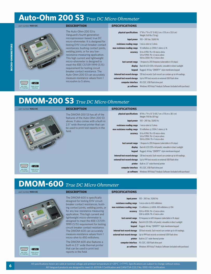
physical specifications 17”W x 7”H x 13” D (43.2 cm x 17.8 cm x 33.0 cm)Weight: 16.8 lbs (7.6 kg)
input power 100 – 240 Vac, 50/60 Hz
resistance reading range 1 micro-ohm to 5 ohms
max resistance reading range 10 milliohms @ 200A; 5 ohms @ 1A
accuracy 1A to 4.99A: 1% ±10 micro-ohms5A to 9.99A: 1% ±2 micro-ohms10A to 200A: 1% ±1 micro-ohm
test current range 1 Ampere to 200 Amperes (selectable in 1A steps)
display Back-lit LCD (128 x 64 pixels), viewable in direct sunlight
keypad Rugged, 44-key “QWERTY” style membrane keypad
internal test record storage 128 test records. Each record can contain up to 64 readings.
external test record storage Up to 999 test records on external USB Flash drive
computer interface RS-232C, USB Flash drive port
pc software Windows XP/Vista/7 Analysis Software (included with purchase)
DMOM-200 S3 True DC Micro Ohmmeterspecificationsdescription
physical specifications 18”W x 7”H x 15” D (45.7 cm x 17.8 cm x 38.1 cm)Weight: 19.8 lbs (8.9 kg)
input power 100 – 240 Vac, 50/60 Hz
resistance reading range 1 micro-ohm to 5 ohms
max resistance reading range 10 milliohms @ 200A; 5 ohms @ 1A
accuracy 1A to 4.99A: 1% ±10 micro-ohms5A to 9.99A: 1% ±2 micro-ohms10A to 200A: 1% ±1 micro-ohm
test current range 1 Ampere to 200 Amperes (selectable in 1A steps)
display Back-lit LCD (128 x 64 pixels), viewable in direct sunlight
keypad Rugged, 44-key “QWERTY” style membrane keypad
internal test record storage 128 test records. Each record can contain up to 64 readings.
external test record storage Up to 999 test records on external USB Flash drive
printer Built-in 2.5” wide thermal printer
computer interface RS-232C, USB Flash drive port
pc software Windows XP/Vista/7 Analysis Software (included with purchase)
DMOM-600 True DC Micro Ohmmeterspecificationsdescription
input power 100 – 240 Vac, 50/60 Hz
resistance reading range 1 micro-ohm to 450 milliohms
max resistance reading range 1.5 milliohms @ 600A; 450 milliohms @ 10A
accuracy 10A to 49.9A: 1% ±2 micro-ohms50A to 600A: 1% ±1 micro-ohm
test current range 10 Amperes to 600 Amperes (selectable in 1A steps)
display Back-lit LCD (128 x 64 pixels), viewable in direct sunlight
keypad Rugged, 44-key “QWERTY” style membrane keypad
internal test record storage 128 test records. Each record can contain up to 64 readings.
external test record storage Up to 999 test records on external USB Flash drive
printer Built-in 2.5” wide thermal printer
computer interface RS-232C, USB Flash drive port
pc software Windows XP/Vista/7 Analysis Software (included with purchase)
All specifications herein are valid at nominal voltage and ambient temperature of +25°C (+77°F). Specifications are subject to change without notice.
All Vanguard products are designed to meet UL 61010A-1 Certification and CAN/CSA C22.2 No. 1010.1-92 Certification.
The Auto-Ohm-200 S3 is Vanguard’s fourth generation microprocessor-based, true DC micro-ohmmeter. It is designed for testing EHV circuit-breaker contact resistances, bushing contact joints, welding joints, or for any low-resistance measuring application. This high current and lightweight micro-ohmmeter is designed to meet the IEEE C57.09-1999 (5.15) requirement for testing circuit breaker contact resistance. The Auto-Ohm-200 S3 can accurately measure resistance values from 1 microohm to 5 ohms.
The DMOM-200 S3 has all of the features of the Auto-Ohm 200 S3 above. It also comes with a built-in 2.5” wide thermal printer that can be used to print test reports in the field.
The DMOM-600 is specifically designed for testing EHV circuit-breaker contact resistances, bush-ing contact joints, welding joints, or for any low-resistance measuring application. This high current and lightweight micro-ohmmeter is designed to meet the IEEE C57.09-1999 (5.15) requirement for testing circuit breaker contact resistance. The DMOM-600 can accurately measure resistance values from 1 micro-ohm to 450 milliohms.
The DMOM-600 also features a built-in 2.5” wide thermal printer that can be used to print test reports in the field.
part number 9051-UC
part number 9052-UC
part number 9053-UC

win
ding
res
ista
nce
met
ers
7
WRM-10P Winding Resistance Ohmmeterspecificationsdescription
physical specifications 16.8”W x 12.6”H x 10.6”D (42.6 cm x 32.0 cm x 26.9 cm);Weight: 27 lbs (12.2 kg)
resistance reading range 1 micro-ohm – 2,000 ohms
accuracy 1 – 19,999 micro-ohms: ±0.5% reading, ±1 count;20 – 999 milli-ohms: ±1% reading, ±1 count;1 – 2,000 ohms: ±1.5% reading, ±1 count
test voltage 36 Vdc max
test current range Auto range, 10 Amperes max
display Back-lit LCD Screen (20 characters by 4 lines);viewable in bright sunlight and low-light levels
printer 2.5-inch Wide Thermal Printer
internal test record storage Stores 63 test records of 48 readings each
computer interface RS-232C
pc software Windows XP/Vista/7 software is included with purchase price
cables Three 50-foot test cables, ground cable, power cord and cable bag
All specifications herein are valid at nominal voltage and ambient temperature of +25°C (+77°F). Specifications are subject to change without notice.
All Vanguard products are designed to meet UL 61010A-1 Certification and CAN/CSA C22.2 No. 1010.1-92 Certification.
The WRM-10P is a low resistance ohmmeter with all of the features of the WRM-10 above. In addition to the features of the WRM-10, the WRM-10P includes a built-in 2.5-inch wide thermal printer that allows test results to be printed in the field.
Test records can also be down-loaded to a PC. The WRM-10P supports stand-alone mode or can be computer-controlled.
part number 9033-UC
part number 9056-UC [110V], 9046-UC [220V]
LTCA-10 Load Tap Changer Analyzerspecificationsdescription
physical specifications 21”W x 9” H x 17”D (53 cm x 24 cm x 43 cm);Weight: 33 lbs (15.4 kg)
resistance channels 3 static resistance reading channels, 1 dynamic resistance channel
accuracy 1 – 19,999 micro-ohms: ±0.5% reading, ±1 count; 20 – 999 milli-ohms: ±1% reading, ±1 count; 1 – 500 ohms: ±1.5% reading, ±1 count
test voltage 60 Vdc max
test currents 1 ampere, 5 amperes, 10 amperes
load tap changer contact 240 Vac, 1A
display Back-lit LCD Screen (64 x 128 dot graphic );viewable in bright sunlight and low-light levels
printer 4.5-inch wide thermal printer
computer interfaces RS-232C, USB, USB Flash drive port
cables One 50-foot current cable set, Three 50-foot resistance cable sets, One ground cable, One USB cable, One RS-232C cable, One LTC cable, power cord, cable bag
LTCA-40 Load Tap Changer Analyzerspecificationsdescription
physical specifications 25”W x 8.5”H x 20”D (63.5 cm x 21.6 cm x 50 cm);Weight: 46 lbs (20 kg)
resistance channels 3 static resistance reading channels, 1 dynamic resistance channel
resistance reading range 1 micro-ohm – 500 ohms
accuracy 1 – 19,999 micro-ohms: ±0.5% reading, ±1 count; 20 – 999 milli-ohms: ±1% reading, ±1 count; 1 – 500 ohms: ±1.5% reading, ±1 count
test voltage 60 Vdc max
test currents 1 ampere, 5 amperes, 10 amperes, 40 amperes
load tap changer contact 240 Vac, 1A
display Back-lit LCD Screen (64 x 128 dot graphic );viewable in bright sunlight and low-light levels
printer 4.5-inch wide thermal printer
computer interfaces RS-232C, USB, USB Flash drive port
cables One 50-foot current cable set, Three 50-foot resistance cable sets, One ground cable, One USB cable, One RS-232C cable, One current sense cable, One LTC control cable, power cord, cable bag
The LTCA-10 is a transformer winding resistance meter and load tap changer contact analyzer. It is designed to accurately measure the winding resistance of highly inductive power transformers. The unit’s triple resistance-reading input channels can measure three winding resistances simultaneously, and four-wire (Kelvin) connections provide high accuracy and require no lead compensation. Also, the LTCA-10 can measure and graph the resistance trace of a transform-er LTC or voltage regulator contact during operation.
The LTCA-40 has all of the features of the LTCA-10, but is capable of outputting a test current up to 40 Amperes.
part number 9059-UC
win
ding
res
ista
nce
met
ers
8
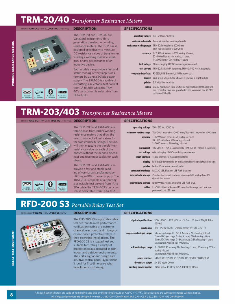
TRM-20/40 Transformer Resistance Metersspecificationsdescription
operating voltage 100 – 240 Vac, 50/60 Hz
resistance channels Two static resistance reading channels
resistance reading range TRM-20: 1 microohm to 2000 OhmsTRM-40: 1 microohm to 500 Ohms
accuracy 1 – 19,999 microohms: ±0.5% reading, ±1 count; 20 – 999 milliohms: ±1% reading, ±1 count; 1 – 2,000 ohms: ±1.5% reading, ±1 count
test voltage 60 Vdc charging, 18 V DC max during measurement
test current TRM-20: 1-20 A in 1A increments, TRM-40: 1-40 A in 1A increments
computer interfaces RS-232C, USB, Bluetooth, USB Flash drive port
display Back-lit LCD Screen (128 x 64 pixels ), viewable in bright sunlight
printer 2.5” wide thermal printer
cables One 50-foot current cable set, two 50-foot resistance sense cable sets, one LTC control cable, one ground cable, one power cord, one RS-232C cable, one USB cable
All specifications herein are valid at nominal voltage and ambient temperature of +25°C (+77°F). Specifications are subject to change without notice.
All Vanguard products are designed to meet UL 61010A-1 Certification and CAN/CSA C22.2 No. 1010.1-92 Certification.
TRM-203/403 Transformer Resistance Metersspecificationsdescription
operating voltage 100 ¬ 240 Vac, 50/60 Hz
resistance reading range TRM-203: 1 micro-ohm ¬ 2000 ohms; TRM-403: 1 micro-ohm ¬ 500 ohms
accuracy 1 ¬ 19,999 micro-ohms: ±0.5% reading, ±1 count;20 ¬ 999 milli-ohms: ±1% reading, ±1 count;1 ¬ 2000 ohms: ±1.5% reading, ±1 count
test current TRM-203: 1A ¬ 20A in 1A increments; TRM-403: 1A ¬ 40A in 1A increments
test voltage 60Vdc charging, 18V DC max during measurement
input channels 4 input channels for measuring resistance
display back-lit LCD Screen (128 x 64 pixels); viewable in bright light and low light
printer built-in 2.5-inch wide thermal printer
computer interfaces RS-232C, USB, Bluetooh, USB Flash drive port
internal data storage 256 static test records (each can contain up to 111 readings) and 120 dynamic test records
external data storage up to 999 test records on external USB Flash drive.
cables four 50-foot test cables, one LTC control cable, one ground cable, one power cord, one USB cable
The TRM-20 and TRM-40 are Vanguard Instruments’ third generation transformer winding resistance meters. The TRM line is designed specifically to measure DC resistance values of transformer windings, rotating machine wind-ings, or any dc resistance of an inductive device.
Both models can provide a fast and stable reading of very large trans-formers by using a 60Vdc power supply. The TRM-20 is capable of outputting a selectable test current from 1A to 20A while the TRM-40’s test current is selectable from 1A to 40A.
The TRM-203 and TRM-403 are three phase transformer winding resistance meters that allow the user to connect all test cables to the transformer bushings. The unit will then measure the transformer resistance value for each of the phases without the need to discon-nect and reconnect cables for each phase.
The TRM-203 and TRM-403 can provide a fast and stable read-ing of very large transformers by utilizing a 60Vdc power supply. The TRM-203 is capable of outputting a selectable test current from 1A to 20A while the TRM-403‘s test cur-rent is selectable from 1A to 40A.
part no. 9007-UC [TRM-20], 9061-UC [TRM-40]
part no. 9060-UC [TRM-203], 9006-UC [TRM-403]
RFD-200 S3 Portable Relay Test Setspecificationsdescription
physical specifications 17”W x 12K”H x 12”D, (42.7 cm x 32.0 cm x 30.5 cm); Weight: 35 lbs (15.9 kg)
input power 100 ¬ 120 Vac or 200 ¬ 240 Vac (factory pre-set), 50/60 Hz
ampere meter input ranges Internal input range: 0 ¬ 250 A; Accuracy: 2% of reading ±10 mA, External AC input range: 0 ¬ 6A; Accuracy: 1% of reading ±10mA;External DC input range: 0 – 6A; Accuracy: 0.5% of reading ±1 countMeasurement Method: True RMS for AC
volt meter input range 0 ¬ 600.0V; AC accuracy: 1% of reading ±1 count; DC accuracy 0.5% of reading ±1 countMeasurement Method: True RMS for AC
power resistors 5 /50 W, 1 /50 W, 25 /50 W, 100 /50 W, 500 /50 W
dry contact output 3A, 240 Vac or 120 Vdc
auxiliary power supplies 24 Vdc @ 1 A, 48 Vdc @ 0.25 A, 124 Vdc @ 0.125 A
rela
y te
st e
quip
men
t
The RFD-200 S3 is a portable relay test set that delivers performance verification testing of electrome-chanical, electronic, and micropro-cessor-based protective relays in their operating installations. The RFD-200 S3 is a rugged test set suitable for testing a variety of protection relays operated in both indoor and outdoor environments. The unit’s ergonomic design and intuitive control panel layout make it ideal for first-time users who have little or no training.
part number 9032-UC [110V], 9082-UC [220V]

win
ding
res
ista
nce
met
ers
9
TSB Trip Saver Box
All specifications herein are valid at nominal voltage and ambient temperature of +25°C (+77°F). Specifications are subject to change without notice.
All Vanguard products are designed to meet UL 61010A-1 Certification and CAN/CSA C22.2 No. 1010.1-92 Certification.
The Vanguard TSB can be used with a Vanguard ATRT-03 series turns ratio tester to perform transformer turns ratio tests using the same cable set provided with the TRM-203/403. Using the TSB, there is no need to con-nect and reconnect cables from the transformer after the initial connections are made. The user can conveniently perform resistance tests using the TRM-203/403 and turns ratio tests using an ATRT-03 without having to make trips to the transformer to connect and disconnect cables.
part number 9062-UC
PCI-600 600 Amp Primary Current Injection Sourcespecificationsdescription
input power 100 – 120 Vac or 200 – 240 Vac (factory pre-set), 50/60 Hz
output current 10 - 600 A
internal current meter 100 mA – 1000 A; Accuracy: 1% of reading, ±20 mA
external meter range 10 mA – 10 A; Accuracy: 1% of reading, ±2 mA
timer reading range 1 ms – 2 hours; Accuracy: 0.1% of reading ±1ms
timer stop input Voltage input (24 – 300 V, DC or peak AC), dry-contact input, or removal of primary current
cables 10-foot #1/0 AWG test leads, power cord, ground cable
The PCI-600 is a programmable AC high-current source designed specifically for utility-substation applications. The PCI-600 injects a current on a substation bus to verify the relay settings and CT output.
This versatile device can also be used for testing thermal, magnetic, and solid-state motor-protection relays and molded-case circuit-breakers, as well as any application that requires a high-current source. re
lay
test
equ
ipm
ent
part number 9029-UC [110V], 9058-UC [220V]

MCCB-250 Molded Case Circuit Breaker Tester
circ
uit
brea
ker
anal
yzer
s
10
specificationsdescription
input power 100 – 120 Vac or 200 – 240 Vac (factory pre-set), 50/60 Hz
output currents 0 – 5 A @ 120 Vac max; 0 – 25 A @ 24 Vac max;0 – 120 A @ 6 Vac max; 0 – 250 A @ 3 Vac max
internal current meter 100 mA – 1000 A; Accuracy: 1% of reading ±20mA
external meter range 10 mA – 10 A; Accuracy: 1% of reading, ±2mA
timer reading range 1ms – 2 hours; Accuracy: 0.1% of reading ±1ms
timer stop inputs Voltage input (24V – 300V, DC or peak AC), dry contact input, or removal of primary current
display Back-lit LCD Screen (20 characters by 4 lines);viewable in bright sunlight and low-light levels
cables Power cord, ground cable, 10-foot #2 AWG test leads
CT-3500 S2 Digital Circuit Breaker Analyzerspecificationsdescription
input power 100 ¬ 240 Vac, 50/60 Hz
dry-contact inputs 3 channels
trigger input voltage open/close: 30 ¬ 300 V, DC or peak AC
breaker operations Open, Close, Open-Close, Close-Open
timing resolution ±0.1 millisecond; accuracy: 0.05% of reading ±0.1 ms
display back-lit LCD screen (128 x 64 pixels); viewable in bright sunlight and low light conditions
keypad rugged, 44-key "QWERTY" membrane keypad
printer built-in 2.5-inch wide thermal printer
internal test record storage stores up to 128 timing records
computer interfaces one USB PC interface, one USB Flash drive port
pc software Windows® based Breaker Analysis software included with purchase price
cables furnished with full set of test leads (inluding 20-foot contact leads and 30-foot contact lead extensions)
DigiTMR S2 Digital Circuit Breaker Analyzerspecificationsdescription
input power 3 Amps, 100 ¬ 240 Vac, 50/60 Hz
dry-contact inputs 3 dry-contact channels; each channel detects main contact and insertion resistor contact
timing windows 1 second, 10 seconds, or 20 seconds
timing resolutions ±50 micro-seconds @ 1 sec. duration, ±500 micro-seconds @ 10 sec. duration, ±1.0 milli-seconds @ 20 sec. duration
timing accuracy 0.05% of reading ±0.1 milli-seconds @ 1 second duration
insertion resistor detection 50 ¬ 5,000 ohms
breaker initiate capacity 30A, 250 Vac/dc max
voltage sensing input range V1: analog input; 0 ¬ 255 V DC or peak AC; sensitivity ±1 VV2: voltage presence/absence detector input; 30 ¬ 300 V DC or peak AC
breaker operations Initiate Open, Close, Open-Close, Close-Open, Open-Close-Open
digital travel transducer input 1 digital travel transducer channel; linear range: 0.0 ¬ 60.0 in (±0.005 in)rotary range: 0 ¬ 360 degrees (±0.006 degrees)
printer built-in 4.5” wide thermal printer that can print both graphic contact travel waveforms and tabulated test results
computer interfaces one USB port, optional Bluetooth interface, USB Flash drive port
All specifications herein are valid at nominal voltage and ambient temperature of +25°C (+77°F). Specifications are subject to change without notice.
All Vanguard products are designed to meet UL 61010A-1 Certification and CAN/CSA C22.2 No. 1010.1-92 Certification.
The MCCB-250 is a programmable, high-current source designed specifically for testing molded-case circuit breakers, thermal magnetic and solid-state overload motor-protection relays. The MCCB-250’s built-in digital timer displays test results in milliseconds and cycles (with 1 ms resolution). The digital current meter displays test current. External current input allows the user a quick way to verify CT turns ratio.
The CT-3500 S2 is Vanguard’s second generation, stand-alone, digital, micro-processorcontrolled, circuit-breaker timer. It measures the elapsed time from the instant a breaker coil is energized to the instant of opening or closing of a circuit-breaker’s dry contacts. In addition to timing a breaker’s contact response time, the CT-3500 S2 can also time relays or other switching functions that use an initiating trigger voltage (30-300 Volts DC or AC).
The CT-3500 can fully analyze the timing of all circuit breaker operations (Open, Close, Open – Close, and Close – Open). Timing results are displayed in milli-seconds and cycles on the unit’s back-lit LCD screen and can be printed on the built-in 2.5-inch wide thermal printer.
The Vanguard DIGITMR S2 is an inexpensive, easy to use digital cir-cuit breaker analyzer. The DIGITMR S2 can be operated stand-alone or can be computer-controlled. It can fully analyze a circuit-breaker’s performance by testing the contact time, stroke, velocity, over-travel, and contact wipe. Contact and motion analysis can be performed for all breaker contact operations (Open, Close, Open – Close, Close – Open, and Open – Close – Open). Timing results are recorded and displayed on the 240 x 128 pixels back-lit LCD screen and can also be printed on the built-in 4.5" wide thermal printer.
part number 9002-UC
part number 9005-UC
part number 9066-UC [110V], 9067-UC [220V]

DigiTMR S2 PC Digital Circuit Breaker Analyzer
circ
uit
brea
ker
anal
yzer
s
11
specificationsdescription
input power 3 Amps, 100 ¬ 240 Vac, 50/60 Hz
dry-contact inputs 3 dry-contact channels; each channel detects main contact and insertion resistor contact
timing windows 1 second, 10 seconds, or 20 seconds
timing accuracy 0.05% of reading ±0.1 milli-seconds @ 1 second duration
insertion resistor detection 50 ¬ 5,000 ohms
breaker initiate capacity 30A, 250 Vac/dc max
voltage sensing input range V1: analog input; 0 ¬ 255 V DC or peak AC; sensitivity ±1 VV2: voltage presence/absence detector input; 30 ¬ 300 V DC or peak AC
breaker operations Initiate Open, Close, Open-Close, Close-Open, Open-Close-Open
digital travel transducer input 1 digital travel transducer channel; linear range: 0.0 ¬ 60.0 in (±0.005 in)rotary range: 0 ¬ 360 degrees (±0.006 degrees)
computer interfaces one USB port, optional Bluetooth interface
pc software Windows®-based Circuit Breaker Analysis Series 2 (VCBA S2) software included with purchase price. Software updates available at no additional charge
CT-7000 S3 Digital Circuit Breaker Analyzerspecificationsdescription
All specifications herein are valid at nominal voltage and ambient temperature of +25°C (+77°F). Specifications are subject to change without notice.
All Vanguard products are designed to meet UL 61010A-1 Certification and CAN/CSA C22.2 No. 1010.1-92 Certification.
The Vanguard DIGITMR S2 PC is an inexpensive, easy to use digital circuit breaker analyzer that is designed to be used with a PC. This inexpensive analyzer offers the most cost-effective method for testing circuit breakers. It can fully analyze a circuit-breaker’s performance by testing the contact time, stroke, velocity, over-travel, and contact wipe. Contact-motion analysis can be performed for all breaker contact opera-tions (Open, Close, Open – Close, Close – Open, and Open – Close – Open). The DIGITMR S2 PC offers three dry-contact channels (for timing circuit breaker main and insertion resistor contacts), one digital transducer channel (to monitor CB contact motion), and two voltage monitoring channels.
The CT-7000 S3 is Vanguard's fourth generation EHV circuit breaker analyzer. The CT-7000 S3 is available with 3 (9021-UC) or 6 contact timing channels (9100-UC). The CT-7000 S3 can fully ana-lyze a circuit breaker's performance by measuring the main contact and resistor contact time, stroke, veloc-ity, over-travel, bounce back and contact wipes. Both contact and motion analysis can be performed on all circuit breaker operations. The CT-7000 S3's timing window is selectable between 1 second, 10 seconds, and 20 seconds.
part number 9068-UC
please see description for part numbers
CT-8000 S3 Digital Circuit Breaker Analyzerspecificationsdescription
dry-contact inputs 3 or 6 dry-input channels (depending on model). Each channel detects main and insertion-resistor contacts
timing windows 1-second, 10-seconds, or 20-seconds
timing accuracy 0.05% of reading ±0.05 ms @ 1-second duration
contact resistance reading 1 micro-ohm - 2,000 micro-ohms , 200 A / 5 Vdc power supply;
voltage sensing input range V1: analog input; 0–250 V, dc or peak ac, Sensitivity: ±1 VV2 and V3: voltage detector (present/absent) input; 24-255V, dc or peak ac
breaker operations Open, Close, Open-Close, Close-Open, Open-Close-Open
breaker initiate capacity 30A, 250Vac/dc max
initiate current reading range One, non-contact, Hall-effect sensor, 0 – 20 amp range, dc to 5Khz
travel transducer inputs 3 digital travel transducer channels; 3 resistor transducer inputs
computer interfaces USB, USB Flash drive, optional Bluetooth
pc software Windows-based software is included with purchase price
internal test record storage Stores up to 200 test records and 100 test plans
optional features Bluetooth, 3-phase on-line timing mode, dual-ground timing mode
The CT-8000 S3 is Vanguard’s fourth generation, stand-alone, microprocessor-driven EHV circuit-breaker analyzer. It is available in models with either 3 (9103-UC) or 6 (9104-UC) dry-contact inputs. The CT-8000 S3 can fully analyze a circuit breaker's performance by measuring the main contact and re-sistor contact time, stroke, velocity, over-travel, bounce back and contact wipes. Also, an outstanding feature of the CT-8000 S3 is the ability to perform dynamic resistance tests on circuit breaker contacts.
The unit’s built-in 4K" wide thermal printer can print test results in the field.
please see description for part numbers
dry-contact inputs 3 or 6 dry-input channels (depending on model). Each channel detects main and insertion-resistor contacts
timing windows 1-second, 10-seconds, or 20-seconds
timing accuracy 0.05% of reading ±0.05 ms @ 1-second duration
voltage sensing input range V1: analog input; 0–250 V, dc or peak ac, Sensitivity: ±1 VV2 and V3: voltage detector (present/absent) input; 24-255V, dc or peak ac
breaker operations Open, Close, Open-Close, Close-Open, Open-Close-Open
breaker initiate capacity 30A, 250Vac/dc
initiate current reading range Three, non-contact, Hall-effect sensors, 0 – 20 amp range, dc to 5Khz ac
travel transducer inputs 3 digital travel transducer channels; 3 resistor-type transducer channels
computer interfaces USB, USB Flash drive, optional Bluetooth
pc software Windows-based software is included with purchase price
internal test record storage Stores up to 200 test records and 100 test plans
optional features Bluetooth, 3-phase on-line timing mode, dual-ground timing mode
circ
uit
brea
ker
anal
yzer
s
12
UPS S2 Universal Power Supplyspecificationsdescription
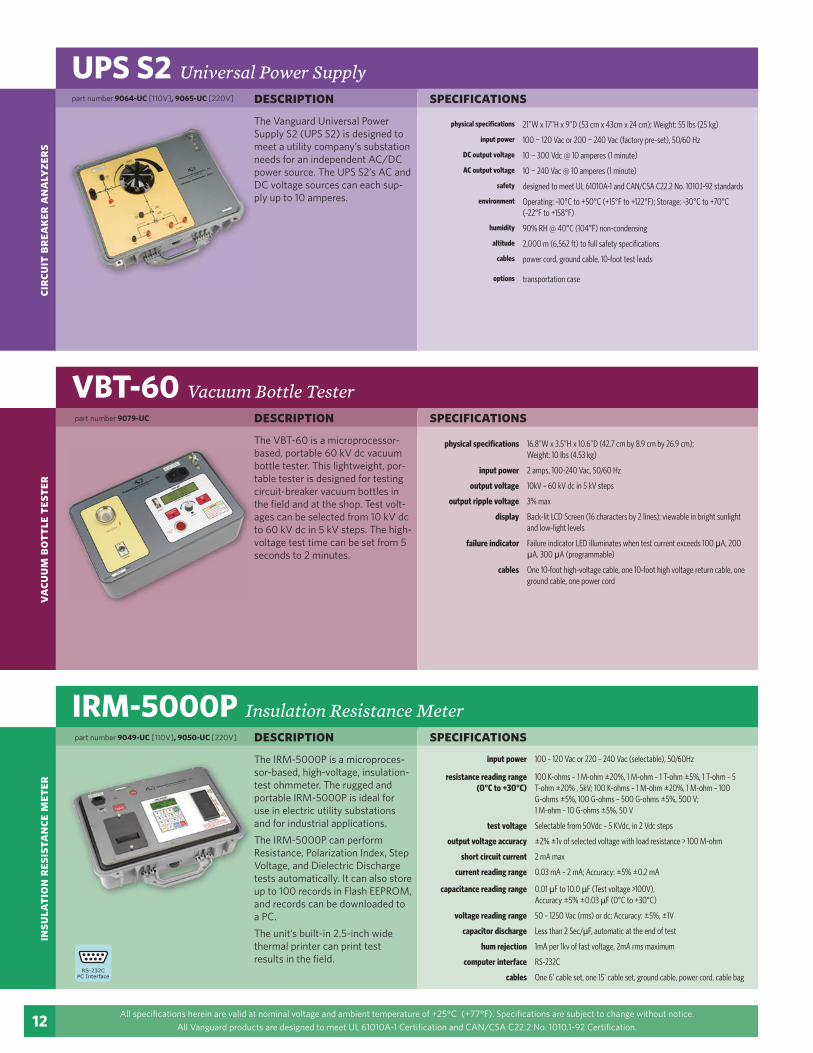
physical specifications 21"W x 17"H x 9"D (53 cm x 43cm x 24 cm); Weight: 55 lbs (25 kg)
input power 100 ¬ 120 Vac or 200 ¬ 240 Vac (factory pre-set), 50/60 Hz
DC output voltage 10 ¬ 300 Vdc @ 10 amperes (1 minute)
AC output voltage 10 ¬ 240 Vac @ 10 amperes (1 minute)
safety designed to meet UL 61010A-1 and CAN/CSA C22.2 No. 1010.1-92 standards
environment Operating: -10°C to +50°C (+15°F to +122°F); Storage: -30°C to +70°C (-22°F to +158°F)
humidity 90% RH @ 40°C (104°F) non-condensing
altitude 2,000 m (6,562 ft) to full safety specifications
cables power cord, ground cable, 10-foot test leads
options transportation case
All specifications herein are valid at nominal voltage and ambient temperature of +25°C (+77°F). Specifications are subject to change without notice.
All Vanguard products are designed to meet UL 61010A-1 Certification and CAN/CSA C22.2 No. 1010.1-92 Certification.
The Vanguard Universal Power Supply S2 (UPS S2) is designed to meet a utility company’s substation needs for an independent AC/DC power source. The UPS S2’s AC and DC voltage sources can each sup-ply up to 10 amperes.
part number 9064-UC [110V], 9065-UC [220V]
VBT-60 Vacuum Bottle Testerspecificationsdescription
physical specifications 16.8”W x 3.5”H x 10.6”D (42.7 cm by 8.9 cm by 26.9 cm);Weight: 10 lbs (4.53 kg)
input power 2 amps, 100-240 Vac, 50/60 Hz
output voltage 10kV – 60 kV dc in 5 kV steps
output ripple voltage 3% max
display Back-lit LCD Screen (16 characters by 2 lines); viewable in bright sunlight and low-light levels
failure indicator Failure indicator LED illuminates when test current exceeds 100 A, 200 A, 300 A (programmable)
cables One 10-foot high-voltage cable, one 10-foot high voltage return cable, one ground cable, one power cord
The VBT-60 is a microprocessor-based, portable 60 kV dc vacuum bottle tester. This lightweight, por-table tester is designed for testing circuit-breaker vacuum bottles in the field and at the shop. Test volt-ages can be selected from 10 kV dc to 60 kV dc in 5 kV steps. The high-voltage test time can be set from 5 seconds to 2 minutes.
IRM-5000P Insulation Resistance Meterspecificationsdescription
input power 100 – 120 Vac or 220 – 240 Vac (selectable), 50/60Hz
resistance reading range(0°C to +30°C)
100 K-ohms – 1 M-ohm ±20%, 1 M-ohm – 1 T-ohm ±5%, 1 T-ohm – 5 T-ohm ±20% , 5kV; 100 K-ohms – 1 M-ohm ±20%, 1 M-ohm – 100 G-ohms ±5%, 100 G-ohms – 500 G-ohms ±5%, 500 V;1 M-ohm – 10 G-ohms ±5%, 50 V
test voltage Selectable from 50Vdc – 5 KVdc, in 2 Vdc steps
output voltage accuracy ±2% ±1v of selected voltage with load resistance > 100 M-ohm
short circuit current 2 mA max
current reading range 0.03 mA – 2 mA; Accuracy: ±5% ±0.2 mA
capacitance reading range 0.01 μF to 10.0 μF (Test voltage >100V),Accuracy ±5% ±0.03 μF (0°C to +30°C)
voltage reading range 50 – 1250 Vac (rms) or dc; Accuracy: ±5%, ±1V
capacitor discharge Less than 2 Sec/μF, automatic at the end of test
hum rejection 1mA per 1kv of fast voltage, 2mA rms maximum
computer interface RS-232C
cables One 6' cable set, one 15' cable set, ground cable, power cord, cable bag
The IRM-5000P is a microproces-sor-based, high-voltage, insulation-test ohmmeter. The rugged and portable IRM-5000P is ideal for use in electric utility substations and for industrial applications.
The IRM-5000P can perform Resistance, Polarization Index, Step Voltage, and Dielectric Discharge tests automatically. It can also store up to 100 records in Flash EEPROM, and records can be downloaded to a PC.
The unit’s built-in 2.5-inch wide thermal printer can print test results in the field.
part number 9079-UC
part number 9049-UC [110V], 9050-UC [220V]
vacu
um b
ottl
e te
ster
insu
lati
on r
esis
tanc
e m
eter
vanguard-instruments.com
13
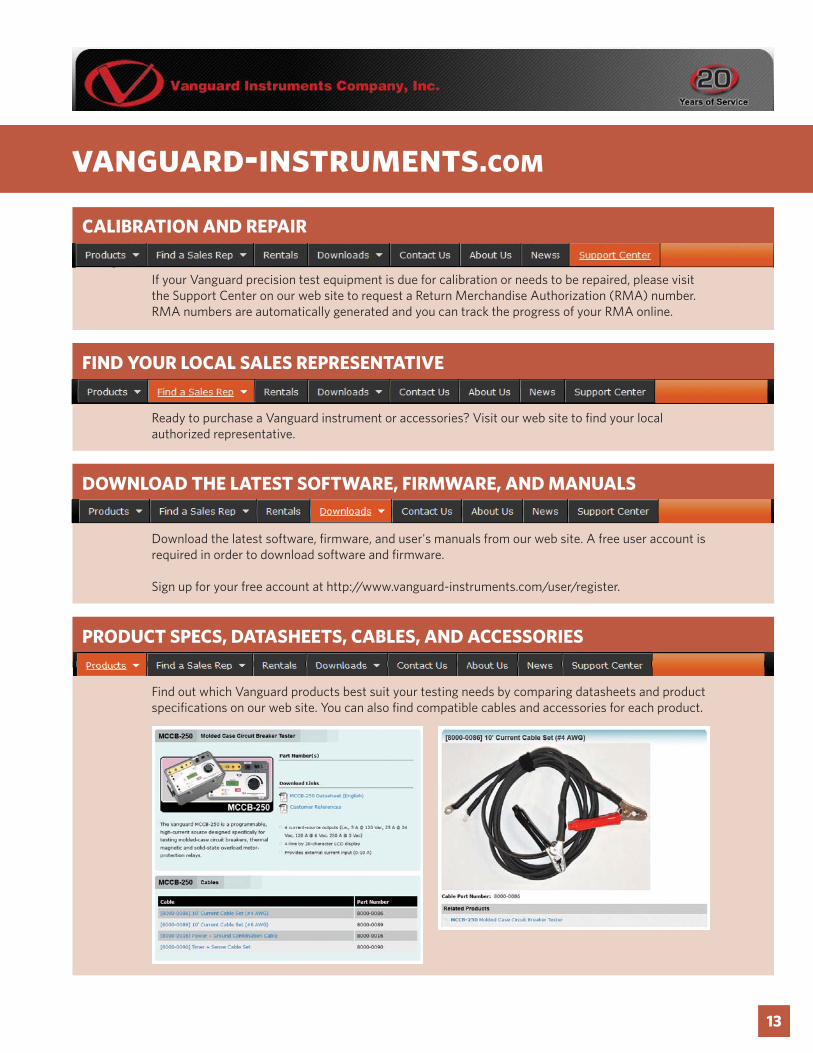
CALIBRATION AND REPAIR
If your Vanguard precision test equipment is due for calibration or needs to be repaired, please visit the Support Center on our web site to request a Return Merchandise Authorization (RMA) number. RMA numbers are automatically generated and you can track the progress of your RMA online.
Ready to purchase a Vanguard instrument or accessories? Visit our web site to find your local authorized representative.
FIND YOUR LOCAL SALES REPRESENTATIVE
Download the latest software, firmware, and user's manuals from our web site. A free user account is required in order to download software and firmware.
Sign up for your free account at http://www.vanguard-instruments.com/user/register.
DOWNLOAD THE LATEST SOFTWARE, FIRMWARE, AND MANUALS
Find out which Vanguard products best suit your testing needs by comparing datasheets and product specifications on our web site. You can also find compatible cables and accessories for each product.
PRODUCT SPECS, DATASHEETS, CABLES, AND ACCESSORIES
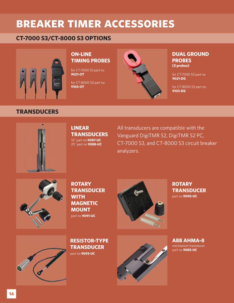
ABB AHMA-8mechanism transducerpart no 9085-UC
LINEARTRANSDUCERS10" part no 9087-UC25" part no 9088-UC
ROTARYTRANSDUCERpart no 9090-UC
ROTARYTRANSDUCERWITHMAGNETICMOUNTpart no 9091-UC
RESISTOR-TYPETRANSDUCERpart no 9093-UC
breaker timer accessories
All transducers are compatible with the
Vanguard DigiTMR S2, DigiTMR S2 PC,
CT-7000 S3, and CT-8000 S3 circuit breaker
analyzers.
ON-LINETIMING PROBES
for CT-7000 S3 part no 9021-OT
for CT-8000 S3 part no 9103-OT
DUAL GROUNDPROBES (3 probes)
CT-7000 S3/CT-8000 S3 OPTIONS
TRANSDUCERS
for CT-7000 S3 part no 9021-DG
for CT-8000 S3 part no 9103-DG
14
15
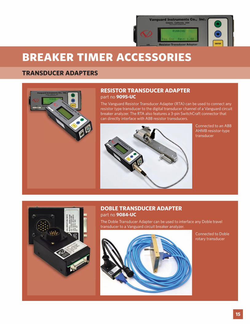
RESISTOR TRANSDUCER ADAPTERpart no 9095-UCThe Vanguard Resistor Transducer Adapter (RTA) can be used to connect any resistor type transducer to the digital transducer channel of a Vanguard circuit breaker analyzer. The RTA also features a 3-pin SwitchCraft connector that can directly interface with ABB resistor transducers.
DOBLE TRANSDUCER ADAPTERpart no 9084-UCThe Doble Transducer Adapter can be used to interface any Doble travel transducer to a Vanguard circuit breaker analyzer.
Connected to an ABB AHMB resistor-type transducer
Connected to Doble rotary transducer
breaker timer accessoriesTRANSDUCER ADAPTERS

Instruments designed and developedby the hearts and minds of utilityelectricians around the world
Vanguard Instruments Company, (VIC), was founded in 1991. Currently, our 28,000 square-foot facility houses Administration, Design & Engineering, and Manufacturing operations. From its inception, VIC’s vision was, and is to develop and manufacture innovative test equipment for use in testing substation EHV circuit breakers and other electrical apparatus.
The first VIC product was a computerized circuitbreaker analyzer, which was a resounding success. It became the forerunner of an entire series of circuitbreaker test equipment. Since its beginning, VIC’s product line has expanded to include microcomputer-based, precision micro-ohmmeters, single and three phase transformer winding turns-ratio testers, transformer winding-resistance meters, mega-ohm resistance meters, and a variety of other electrical utility maintenance support products.
VIC’s performance-oriented products are well suited for the utility industry. They are rugged, reliable, accurate, user friendly, and most are computer controlled. Computer control, with innovative programming, provides many automated testing functions. VIC’s instruments eliminate tedious and time-consuming operations, while providing fast, complex, test-result calculations. Errors are reduced and the need to memorize long sequences of procedural steps is eliminated. Every VIC instrument is competitively priced and is covered by a liberal warranty.
Vanguard Instruments Company, Inc.
Phone Fax 909-923-9391www.vanguard-instruments.com
5th Edition, August 5th, 2013


