
0708-F-011 CRYOGENIC- ASSISTED HIGH SPEED MACHINING
SUE-RYNLEY ANAK EMLEY
UNIVERSITY MALAYSIA PAHANG

0708-F-011 CRYOGENIC- ASSISTED HIGH SPEED MACHINING
SUE-RYNLEY ANAK EMLEY
A report submitted in partial fulfillment of the requirements for the award of the degree of
Bachelor of Mechanical Engineering With Manufacturing Engineering
Faculty of Mechanical Engineering
UNIVERSITY MALAYSIA PAHANG
NOVEMBER 2008

To my Beloved Parents
EMLEY AHUA
LIMGIME EMLEY NEGGOG

ACKNOWLEDGEMENTS
I would like to express profound gratitude to my advisor, Dr. Mon Thet Thet for her
invaluable support, encouragement, supervision and useful suggestions throughout this
research work. Her moral support and continuous guidance enabled me go through the
rough road to complete my work successfully. I am also highly thankful to Mr. Zamzuri
Hamedon, my co-supervisor for his valuable guides and suggestions throughout this study.
I am grateful for the cooperation of lab assistant by helping me in machine usage.
First, I really appreciate the kindness of Mr. Asmizam Mokhtar, Assistant Instructor
Enginner, who gave me so much help in using lathe machine. Secondly, Mr. Hazami Che
Hussain, the Instructor Engineer who assist me in using the image analyzer. He was willing
to help me answer all my questions regarding image analyzer without hesitation. I am also
thankful to Mr. Lee Giok Chui, and Mr. Mohd. Reza Zalani, my project panels which
contributed some useful comments during my experiment. Moreover, I would like to
acknowledge all of my friends especially Hazwan Aizat, Nur Farhanah Zakaria, Mohd.
Shamsul Shahrir who offer me their helping hand in my project.
I am as ever, especially indebted to my parents, Mr. and Mrs, Limgime Emley for
their love and support throughout my life even I am so far away from them and spending
most of my life abroad. I also wish to thank my bestfriend, Mr. Alson Albert Au for his
support and understanding during my study. Finally, I wish to express my appreciation to
my Manufacturing friends, who shared their love and experiences with me.

ABSTRACT
Titanium and its alloys are widely used in various industries mainly aviation.
However, it is considered as difficult-to-machine material due to its unusual high cutting
temperature, which leads to many research works on machinability of this material. In the
current work, tool wear of titanium aluminum nitride (TiAlN) coating insert in turning of
Ti-6Al-4V have been experimentally studied under conventional wet and cryogenic
cooling. After each machining time, the tool edge was observed under microscope. Wear
images were captured and analyzed by the image analyzer to identify different forms of
wear occurrence. Experimental results have shown that for high cutting speed cutting,
insert worn rapidly and also chipped in the case of wet turning, whereas no appreciable
wear was found in cryogenic turning. In summary, this project achieved the objectives
whereby the cryogenic coolant give positive influence on the tool wear.

ABSTRAK
Aplikasi penggunaan titanium dan titanium alloy pada hari ini amat meluas
terutama dalam bidang aeroangkasa. Walaubagaimanapun, bahan ini dikategorikan
sebagai bahan-sukar-dimesin di atas faktor penjanaan suhu memotong yang luar biasa,
dimana ini telah menyumbang kepada pelbagai kerja penyelidikan bagi mengenal pasti
sifat bahan ini. Dalam projek ini, kehausan mata alat titanium aluminum nitride (TiAlN)
semasa proses larikan Ti-6Al-4V dengan cecair penyejuk tradisional dan cecair penyejuk
jenis cryogenic telah dikaji secara experimen. Muka alat dikaji selepas satu jangka masa
proses larikan dibuat. Gambar kehausan yang berlaku di mata alat diambil dan dianalisis
dengan menggunakan “image analyzer”. Hasil kajian pada kelajuan memotong tinggi
menunjukkan mata alat mengalami kehausan yang cepat dan mata alat turut terserpih
semasa proses penyejukan tradisional digunakan, manakala tiada kehausan mata alat
berlaku ketika penyejuk cryogenic diaplikasi. Sebagai kesimpulan, projek yang telah
dijalankan mencapai objektif dimana cecair penyejuk jenis cryogenic mampu memberi
kesan positif kepada kehausan mata alat.
TABLE OF CONTENTS
Page
SUPERVISOR’S DECLARATION ii
STUDENT’S DECLARATION iii
DEDICATION iv
ACKNOWLEDGEMENTS v
ABSTRACT vi
ABSTRAK vii
TABLE OF CONTENTS viii
LIST OF TABLES xi
LIST OF FIGURES xii
LIST OF APPENDIX xiv
CHAPTER 1 INTRODUCTION
1.1 Introduction 1
1.2 Project Background 1
1.3 Problem Statement 2
1.4 Project Objective 2
1.5 Scope of Project 3
1.6 Summary 3

CHAPTER 2 LITERATURE REVIEW
2.1 Introduction 4
2.2 Titanium Alloy Machinability 4
2.3 Machining- Turning Process 6
2.4 Cutting Tools 9
2.5 Cutting Fluids 10
2.6 Cryogenic Machining 12
2.7 Tool Wear 15
2.8 Image Analyzer 16
2.9 Machining Parameters for Titanium Alloy 17
CHAPTER 3 METHODOLOGY
3.1 Introduction 18
3.2 Methodology Flow Chart 18
3.3 Literature Study 19
3.4 Workpiece Material 19
3.5 Cutting Tool Material 20
3.6 Machining Test 20
3.7 Tool Wear 23
3.7.1 Tool Wear Measurement 23
3.8 Data Comparison 24
3.9 Summary 24

CHAPTER 4 RESULTS & DISCUSSION
4.1 Introduction 25
4.2 Cutting Speed 25
4.3 Analysis of Tool Wear 26
4.3.1 Flank Wear Analysis 27 4.3.2 Crater Wear Analysis 32
4.4 Summary 37
CHAPTER 5 CONCLUSIONS & RECOMMENDATION
5.1 Introduction 38 5.2 Conclusion 38 5.3 Recommendation 39 REFERENCES 40 APPENDIX
A Gantt Chart for Final Year Project 44 B (I) ISO-Designation of Turning Tool Geometry 45 C (II) ISO-Designation of Turning Tool Geometry 46

LIST OF TABLE
Table No.. Title Page
Table 3.1 Properties of the Ti-6Al-4V 19
Table 3.2 Machining Parameters for Conventional Coolant 22
Table 3.3 Machining Parameters for Cryogenic Coolant 22
Table 4.1 Flank Wear 28
Table 4.2 Crater Wear 33

LIST OF FIGURES
Figure No. Title Page
2.1 Build Up Edge 5
2.2 Cylindrical Turning of Titanium Bar 6
2.3 Schematic of turning process showing cutting speed
(V), feed rate (t) and depth of cut (b). 7
2.4 Terminology used in orthogonal metal cutting 9
2.5 Various turning inserts 10
2.6 Wear forms on turning tools at reusable state 15
3.1 Simple Flow Chart 18
3.2 Triangular Insert and Tool Holder 20
3.3 Turning Process under Cryogenic Cooling 21
3.4 Turning Process under Conventional Coolant 22
3.5 IM 1700 Series Image Analyzer 23
4.1 Tool Wear Growth under Cryogenic Cooling after
65mm Cutting Length 27
4.2 Graph of Tool Flank Wear versus Machining Time 28
4.3 Wear Occurrence on the Tool Flank Face during
Conventional Machining at 110 m/min, depth of cut
1.00 mm, and feed 0.10 mm/ rev. 29
4.4 Wear Occurrence on the Tool Flank Face during
Cryogenic Machining at 110 m/min, depth of cut
1.00 mm, and feed 0.10 mm/ rev. 30
4.5 Wear Occurrence on the Tool Flank Face 31
4.6 Graph of Tool Crater Wear versus Machining Time 33

4.7 Wear Occurrence on the Tool Crater Face during
Conventional Machining at 110 m/min, depth of cut
1.00 mm, and feed 0.10 mm/ rev. 34
4.8 Wear Occurrence on the Tool Crater Face during
Cryogenic Machining at 110 m/min, depth of cut
1.00 mm, and feed 0.10 mm/ rev. 35
4.9 Wear Occurrence on the Tool Crater Face 36
LIST OF APPENDICES
Appendix Title Page
A Gantt Chart for Final Year Project 44
B (I) ISO-Designation of Turning Tool Geometry 45
C (II) ISO-Designation of Turning Tool Geometry 46

0708-F-011 CRYOGENIC- ASSISTED HIGH SPEED MACHINING
SUE- RYNLEY ANAK EMLEY
BACHELOR OF MECHANICAL ENGINEERING WITH MANUFACTURING ENGINEERING
FACULTY OF MECHANICAL ENGINEERING

UNIVERSITI MALAYSIA PAHANG 2008
CHAPTER 1
INTRODUCTION
1.1 Introduction
This chapter gives a brief description of the project progress including approaches o
method application. It includes project background, problem statement, objective and
scope of the project on role play by cryogenic cooling in machining.
1.2 Project Background
Titanium is not a new metal in nowadays industry field. It has approximately 60% of
the density of steel and alloying would greatly strengthen it. Titanium already enter the
industry as a special material with great values such as the combination of high specific
strength, heat resistant, good toughness, and other positive properties allows strength-
weight ratio saving in high-performance application. It is also nonmagnetic and has good
heat-transfer properties. [1]
Titanium popularity increase tremendously these days drive development in
machining technology focused on better productivity. In machining operation, heat
generated during cutting commonly concentrated at the cutting edge of cutting tool and
workpiece. Common prevention way is usage of conventional coolant that would acts as

lubricant at relatively low cutting speeds and cooling at high cutting speeds. Correct use of
coolants will greatly reduce cutting tool wear and prolonged tool life. However,
conventional coolant did not serve as an efficient cooling system. Cryogenic cooling which
uses liquid nitrogen as coolant is the alternative ways to bringing down the heat generated.
1.3 Problem Statement
The titanium alloys that have been introduced on the industry meet the
requirements needed but the drawback is they are among the most troublesome materials to
be machine. The machinability of titanium alloys are limited by their low thermal
conductivity and volume specific heat. The machining problem usually encountered is
high cutting temperature during the cutting operation.
High cutting temperature affects tool wear, dimensional and form accuracy, surface
integrity of the product, inherently characterizes high-speed machining. The excessive tool
wear results from high cutting temperature would cause cutting tools failure due to the
mechanical breakage, cutting edge blunting, or plastic deformation.
1.4 Project Objective
The aim of this study is to investigate the role of cryogenic cooling on the growth
of tool wear in the turning process of titanium alloy, Ti-6Al-4V.
1.5 Scope of Project
The study is focus on turning of Ti-6Al-AV under nitrogen gas, GAN as the
cryogenic coolant. Titanium aluminum nitride coated triangular inserts are selected for
cutting tools. Cylindrical turning of the alloy is carried out on conventional lathe machine.
Machining parameters considered are depth of cut, feed rate and cutting speed. Constant
depth of cut and feed were set based on literature. The cutting speed varied range from 70,
90 and 110 m/min . Tool wear image are captured and measurement done by using IM
1700 Series Image Analyzer.
For comparison purpose, wet turning of Ti-6Al-4V done by using conventional
coolant at machining parameters of 110m/min, depth of cut 1.00mm and feed 0.1 mm/rev.
Tool wear will be compared for the same machining parameters under cryogenic cooling
condition.
1.6 Summary
Chapter 1 has been discussed briefly about project background, problem statement,
objective and scope of the project on role play by cryogenic cooling in machining to
achieve the objective mentioned. This chapter is as a fundamental for the project and act as
a guidelines for project research completion.
CHAPTER 2
LITERATURE REVIEW
2.1 Introduction
From the early stage of the project, various literature studies have been done.
Research journal, books, printed or online conference article were the main source in the
project guides. The reference sources emphasize on important aspect of titanium alloy
machining such as machining parameters, cutting tool, tool wear, surface integrity and the
appropriate coolant application.
2.2 Titanium Alloy Machinability
Machining is a major process in the industry in which turning is among the most
widely used operations. It has wide application and refers to all types of metal removal
which include turning, boring, drilling, reaming, tapping, grinding, milling, gear hobbing
and others. Machining titanium alloys were historically been perceived as a difficult-to-
machine alloys. Most of the time titanium is classified as difficult-to-machine method can
be explained by the properties of this metal as example below [Donachie,1988]:
i. Poor Heat Conductivity

During metal cutting, heat is generated due to the deformation of the material ahead
of the tool and also friction at the tool point Heat is generated by the metal cutting
action causes a change in the temperature of the workpiece, fluid used and the tool.
The heat generated is dissipated to the workpiece, and tool. Titanium alloy’s poor
heat conductivity increases the temperature at tool cutting edge hence it wears off
rapidly.
ii. Work-Hardening Characteristics
Due to its work-hardening characteristics, titanium alloys oppose a complete
absence of ‘built-up edge” which causes the forming of high shearing angle. This
would results high bearing loads per unit area of cutting tool. The combination of
high bearing force and the friction force will cause tremendous increases of heat
hence resulting in rapid tool breakdown.

Figure 2.1: Build Up Edge
iii. Serrated Chips Formation
This type of chip formation creates fluctuations in the cutting force especially when
alpha-beta alloys likewise titanium alloy, Ti-6Al-4V are machined. Severe flank
wear were believed to be partially caused by micro fatigue loading on the tool due
to the vibration force, high temperature generation.
2.3 Machining – Turning Process
Turning is the simplest machining operation used for the study of machinability of
various materials. Typical machine employed for turning process is conventional lathe or
computer-numerical controlled turning center. In either type of machine, basic working
principle is the same. The lathe holds the workpiece in cylindrical shape between two rigid
supports called chuck which revolves about the centre line of the lathe. The spindle
carrying the work is rotated whilst a cutting tool, which is supported in a tool post, is made
to travel in a certain direction depending on the form of surface required. If the tool moves
parallel to the axis of the rotation of the work a cylindrical surface is produced as in Figure
2.2. Major machining parameters involved in turning process are cutting speed, feed rate
and depth of cut. These parameters can be schematically described in Figure 2.3.

Figure 2.2: Cylindrical Turning of Titanium Bar
Figure 2.3.: Schematic of turning process showing cutting speed (V), feed rate (t)
and depth of cut (b).
The term high-speed machining is subjective and relative. It is very often defined
based on the range of cutting speed (V in m/s or m/min) used in the machining. Typical

cutting speed that can be used to machine titanium alloys, for instance, on less rigid
conventional machine may range 50 – 70 m/min. As the new machine is becoming more
rigid, the cutting speed can be increased. Nowadays cutting speed to machine difficult-to-
machine like titanium can be as high as 300 m/min with high rigidity machine [Che-Haron,
2001].
In the study of machining-related problems, metal cutting processes are simplified
into two-dimensional problem. Figure 2.4 describes the terms and their definitions used in
2D orthogonal cutting arrangement. As shown in the right of Figure 2.4, the wedge-shape
tool basically consists of two surfaces intersecting to form the cutting edge. The surface
along which the chip flows is known as the rake face, or simply as the tool face and that
ground back to machined surface is known as the flank.
The depth of the individual layer of material removed by the action of the
tool is known as the undeformed chip thickness. One of the most important variables in
metal cutting is the slope of the face and this slope is specified in orthogonal cutting by the
angle between the tool face and a line perpendicular to the new work surface. This angle is
known as the rake angle. The rake angle can be positive, zero or negative as shown in the
right of Figure 2.4. The tool flank plays no part in the process of chip removal; however
the angle between the flank and the new work surface can significantly affect the tool wear
rate and is defined as the clearance angle.
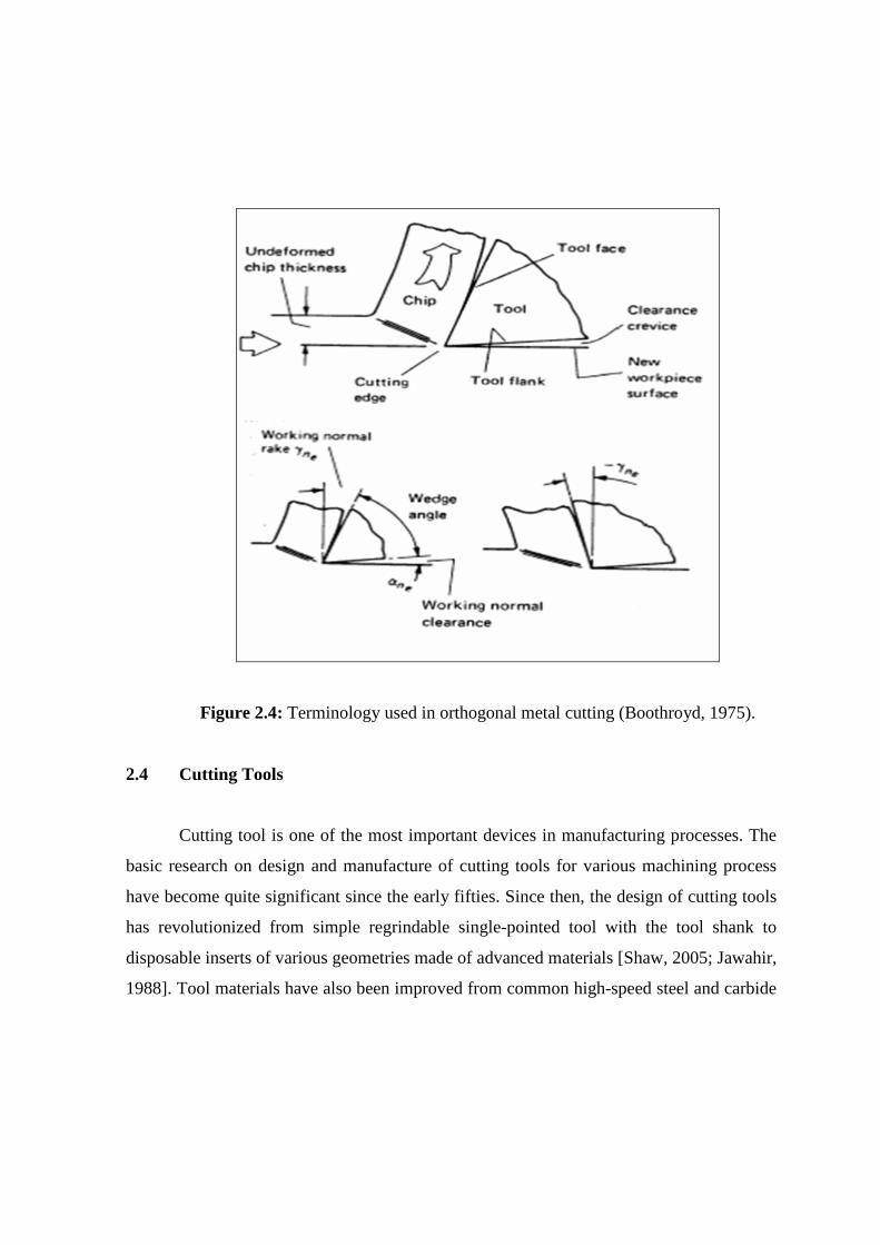
Figure 2.4: Terminology used in orthogonal metal cutting (Boothroyd, 1975).
2.4 Cutting Tools
Cutting tool is one of the most important devices in manufacturing processes. The
basic research on design and manufacture of cutting tools for various machining process
have become quite significant since the early fifties. Since then, the design of cutting tools
has revolutionized from simple regrindable single-pointed tool with the tool shank to
disposable inserts of various geometries made of advanced materials [Shaw, 2005; Jawahir,
1988]. Tool materials have also been improved from common high-speed steel and carbide


