APPLICATION FOR TERMS OF REFERENCE FOR EIA STUDY (REVISED FORM-I & FEASIBILITY REPORT)
for the proposed
4 X 135 MW SURGUJA THERMAL POWER PROJECT
at
DISTRICT SURGUJA, CHHATTISGARH
Submitted to:
Ministry of Environment & Forests, Government of India
Submitted by:
SURGUJA POWER PRIVATE LIMITED Adani House, Near Mithakhali Circle Navrangpura, Ahmedabad – 380009
Gujarat
March 2013
Contents
1. Form-I
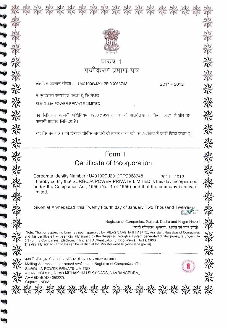
2. Certificate of Incorporation
3. Feasibility Report

4x135 MW Surguja Thermal Power Project Parsa & Kete Villages, Udaypur Tehsil, Surguja Dist. Chhattisgarh
By Surguja Power Private Limited.
Page 1 of 20
FORM-I (I) Basic Information
Sl. Item Details 1. Name of the project/s 540 (4x135) MW Coal Washery Rejects based
Surguja Thermal Power Project of Surguja Power Private Limited.
2. S. No. of the schedule 1 (d) 3. Proposed capacity / area / length
/ tonnage to be handled / command area / lease area / lease area / number of wells to be drilled
Capacity- 540 (4x135) MW Area- 47.479 ha (117.273 Acres)
4. New / Expansion / Modernization New Project 5. Existing Capacity / Area etc. Not Applicable 6. Category of Project i.e. ‘A’ or ‘B’ A (Thermal Power Plant, Capacity ≥ 500 MW) 7. Does it attract the general
condition? If yes please specify. Not Applicable
8. Does it attract the specific condition? If yes please specify.
Not Applicable
9. Location Plot/Survey/Khasra No. Enclosed as Annexure-1 Village Parsa & Kete Tehsil Udaypur District Surguja State Chhatisgarh
10. Nearest Railway Station / Airport alongwith distance in kms.
Ambikapur Railway Station- 60 kms Raipur Airport- 220 kms
11. Nearest Town, city, District Headquarters alongwith distance in kms.
Nearest Town- Udaypur Town (20 kms) Nearest City- Ambikapur (60 kms) District Headquarters- Ambikapur (60 kms)
12. Village Panchayats, Zila Parishad, Municipal Corporation, Local body (complete postal addresses with telephone nos. to be given)
Village Panchayat- Parsa Gram Panchayat Taluka Udaypur District Surguja Chhattisgarh Zila Parishad-Surguja
13. Name of the Applicant Surguja Power Private Limited 14. Registered Address Adani House, Nr. Mithakhali Circle
Navrangpura, Ahmedabad, Gujarat.
15. Address for correspondence Name Mr. Santosh Kumar Singh Designation (Owner / Partner /
CEO) Authorized Signatory
Address 10-A, Sambhav Building, Judges Bungalow Road, Bodakdev Ahmedabad - 380 015
Pin Code 380015

4x135 MW Surguja Thermal Power Project Parsa & Kete Villages, Udaypur Tehsil, Surguja Dist. Chhattisgarh
By Surguja Power Private Limited.
Page 2 of 20
E-mail [email protected] Telephone No. 079-25557289 Fax No. 079-25557176
16. Details of alternative Sites examined, if any Location of these sites should be shown on a topo sheet.
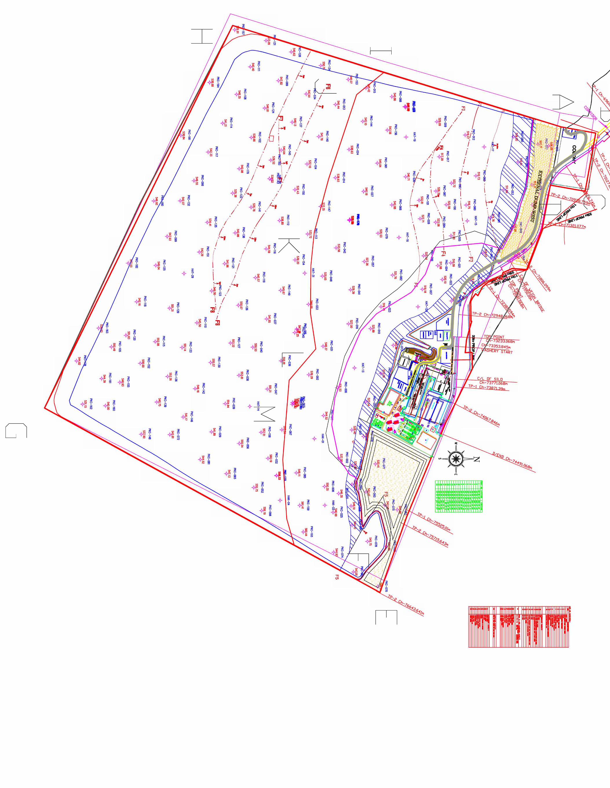
As per the Environmental Clearance Letter No. J-11015/03/2008-IA.II(M) dated 21.12.2011, for Parsa East & Kente Basan Open Cast Coal Mining Project, the location of FBC Power Plant should be within the ML area. The location has been accordingly revised within the Mining Project area.
17. Interlinked Projects Yes, Parsa East and Kente Basan Coal Block of Hasdeo-Arand Coalfield. The coal block has been allotted to Rajasthan Rajya Vidyut Utpadan Nigam Ltd. The mining project and coal washery will be developed and operated by Adani Mining Pvt. Ltd. Surguja Power Private Limited has been formed as SPV, a 100% subsidiary of Adani Mining Private Limited, to implement and operate the Surguja Thermal Power Project. Washed clean coal will be supplied for Thermal Power Plants of Rajasthan Rajya Vidyut Utpadan Nigam Ltd, while the coal washery rejects are proposed to be used by Surguja Power Private Limited for this project.
18. Whether separate application of interlinked project has been submitted?
Yes, Separate application submitted for Coal Block and Coal Washery. The project has been accorded environmental clearance vide letter no. J-11015/03/2008-IA.II(M) dated 21.12.2011.
19. If yes, date of submission 31.12.2007 20. If no, reason Not Applicable 21. Whether the proposal involves
approval / clearance under: if yes, details of the same and their status to be given. (i) The Forest (Conservation) Act, 1980. (ii) The wildlife (Protection) Act, 1972 (iii) The C.R.Z. Notification, 1991
Yes. The Project involves transfer of forest clearance under Forest (Conservation) Act, 1980 for 27.108 ha Protected Forest Land and 2.736 ha of Revenue Forest Land. The Final Approval for diversion of forest land for the Open Cast Coal Mining Project has been accorded for 762 ha. No No
22. Whether there is any Government Order / Policy relevant / relating to the site?
No
23. Forest Land involved (hectares) 29.844 ha 24. Whether there is any litigation
pending against the project and/or land in which the project is propose to be set up?
Not Applicable

4x135 MW Surguja Thermal Power Project Parsa & Kete Villages, Udaypur Tehsil, Surguja Dist. Chhattisgarh
By Surguja Power Private Limited.
Page 3 of 20
(a) Name of the court (b) Case No. (c) Orders/directions of Court, if any and its relevance with the proposed project.
4x135 MW Surguja Thermal Power Project Parsa & Kete Villages, Udaypur Tehsil, Surguja Dist. Chhattisgarh
By Surguja Power Private Limited.
Page 4 of 20
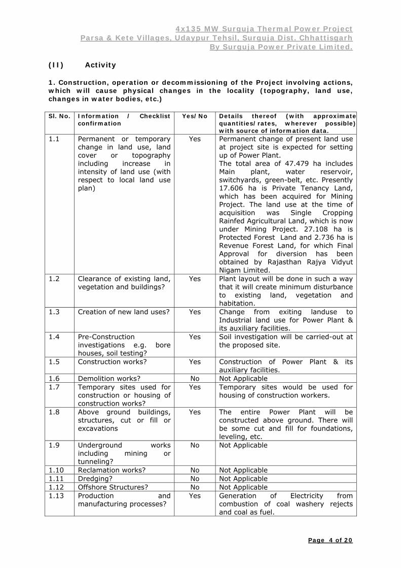
(II) Activity 1. Construction, operation or decommissioning of the Project involving actions, which will cause physical changes in the locality (topography, land use, changes in water bodies, etc.) Sl. No. Information / Checklist
confirmation Yes/No Details thereof (with approximate
quantities/rates, wherever possible)with source of information data.
1.1 Permanent or temporary change in land use, land cover or topography including increase in intensity of land use (with respect to local land use plan)
Yes Permanent change of present land use at project site is expected for setting up of Power Plant. The total area of 47.479 ha includes Main plant, water reservoir, switchyards, green-belt, etc. Presently 17.606 ha is Private Tenancy Land, which has been acquired for Mining Project. The land use at the time of acquisition was Single Cropping Rainfed Agricultural Land, which is now under Mining Project. 27.108 ha is Protected Forest Land and 2.736 ha is Revenue Forest Land, for which Final Approval for diversion has been obtained by Rajasthan Rajya Vidyut Nigam Limited.
1.2 Clearance of existing land, vegetation and buildings?
Yes Plant layout will be done in such a way that it will create minimum disturbance to existing land, vegetation and habitation.
1.3 Creation of new land uses? Yes Change from exiting landuse to Industrial land use for Power Plant & its auxiliary facilities.
1.4 Pre-Construction investigations e.g. bore houses, soil testing?
Yes Soil investigation will be carried-out at the proposed site.
1.5 Construction works? Yes Construction of Power Plant & its auxiliary facilities.
1.6 Demolition works? No Not Applicable 1.7 Temporary sites used for
construction or housing of construction works?
Yes Temporary sites would be used for housing of construction workers.
1.8 Above ground buildings, structures, cut or fill or excavations
Yes The entire Power Plant will be constructed above ground. There will be some cut and fill for foundations, leveling, etc.
1.9 Underground works including mining or tunneling?
No Not Applicable
1.10 Reclamation works? No Not Applicable 1.11 Dredging? No Not Applicable 1.12 Offshore Structures? No Not Applicable 1.13 Production and
manufacturing processes? Yes Generation of Electricity from
combustion of coal washery rejects and coal as fuel.
4x135 MW Surguja Thermal Power Project Parsa & Kete Villages, Udaypur Tehsil, Surguja Dist. Chhattisgarh
By Surguja Power Private Limited.
Page 5 of 20
Sl. No. Information / Checklist confirmation
Yes/No Details thereof (with approximatequantities/rates, wherever possible)with source of information data.
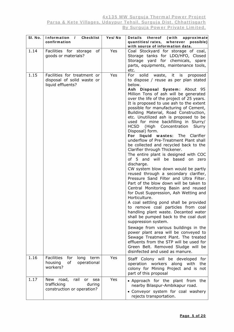
1.14 Facilities for storage of goods or materials?
Yes Coal Stockyard for storage of coal, Storage tanks for LDO/HFO, Closed Storage yard for chemicals, spare parts, equipments, maintenance tools, etc.
1.15 Facilities for treatment or disposal of solid waste or liquid effluents?
Yes For solid waste, it is proposed to dispose / reuse as per plan stated below. Ash Disposal System: About 95 Million Tons of ash will be generated over the life of the project of 25 years. It is proposed to use ash to the extent possible for manufacturing of Cement, Building Material, Road Construction, etc. Unutilized ash is proposed to be used for mine backfilling in Slurry/ HCSD (High Concentration Slurry Disposal) form. For liquid wastes: The Clarifier underflow of Pre-Treatment Plant shall be collected and recycled back to the Clarifier through Thickener. The entire plant is designed with COC of 5 and will be based on zero discharge. CW system blow down would be partly reused through a secondary clarifier, Pressure Sand Filter and Ultra Filter. Part of the blow down will be taken to Central Monitoring Basin and reused for Dust Suppression, Ash Wetting and Horticulture. A coal settling pond shall be provided to remove coal particles from coal handling plant waste. Decanted water shall be pumped back to the coal dust suppression system. Sewage from various buildings in the power plant area will be conveyed to Sewage Treatment Plant. The treated effluents from the STP will be used for Green Belt. Removed Sludge will be disinfected and used as manure.
1.16 Facilities for long term housing of operational workers?
Yes Staff Colony will be developed for operation workers along with the colony for Mining Project and is not part of this proposal
1.17 New road, rail or sea trafficking during construction or operation?
Yes Approach for the plant from the nearby Bilaspur-Ambikapur road.
Conveyor system for coal washery rejects transportation.

4x135 MW Surguja Thermal Power Project Parsa & Kete Villages, Udaypur Tehsil, Surguja Dist. Chhattisgarh
By Surguja Power Private Limited.
Page 6 of 20
Sl. No. Information / Checklist confirmation
Yes/No Details thereof (with approximatequantities/rates, wherever possible)with source of information data. Railway being developed for the
mining project will be used for transportation of coal.
1.18 New road, rail, air, waterborne or other transport infrastructure including new or altered routes and stations, ports, airports etc.?
Yes Conveyor system for coal washery rejects and railway line for coal transportation
Water pipeline from Rehar / Atem river to the plant site
Approach Road for Construction Material Transportation.
1.19 Closure or diversion of existing transport routes or infrastructure leading to changes in traffic movements?
No Not Applicable
1.20 New or diverted transmission lines or pipelines?
Yes New transmission line is proposed from power station to nearest STU / CTU.
1.21 Impoundment, damming, culverting, realignment or other changes to the hydrology of neither watercourses nor aquifers?
No Not Applicable
1.22 Stream crossings? No Not Applicable 1.23 Abstraction or transfers of
water from ground or surface water?
Yes Abstraction of surface water from Atem / Rehar River @ 14.14 MCM per year (39.284 MLD). 1000 KLD of Groundwater abstraction is proposed for domestic and construction purpose.
1.24 Changes in water bodies or the land surface affecting drainage or run off?
No Not significant as water study report of Atem / Rehar River basin, indicates sufficient water is available to cater the need of the project.
1.25 Transport of personnel or materials for construction, operation or decommissioning?
Yes Transport of construction materials from nearby sources to construction work area during construction and transport of coal from washery to the plant site during operation.
1.26 Long-term dismantling or decommissioning or restoration works?
No Not Applicable
1.27 Ongoing activity during decommissioning, which could have impact on the environment?
No Not Applicable
1.28 Influx of people to an area in either temporarily or permanently?
Yes Since industry attracts both skilled and unskilled labours, influx of population will be there to some extent.
1.29 Introduction of alien No Not Applicable

4x135 MW Surguja Thermal Power Project Parsa & Kete Villages, Udaypur Tehsil, Surguja Dist. Chhattisgarh
By Surguja Power Private Limited.
Page 7 of 20
Sl. No. Information / Checklist confirmation
Yes/No Details thereof (with approximatequantities/rates, wherever possible)with source of information data.
species? 1.30 Loss of native species or
genetic diversity? No Not Applicable
1.31 Any other actions? No Not Applicable 2. Use of Natural resources for construction or operation of the Project (such as land, water, materials or energy, especially any resources which are non-renewable or in short supply). Sl.. No.
Information/Checklist confirmation
Yes/No Details thereof (with approximate quantities / rates, wherever possible) with source of information data
2.1 Land especially undeveloped or agricultural (ha)
Yes Presently the entire land has been acquired for the Mining Project, which will be transferred/leased for the Thermal Power Project. Plant layout will be based on minimum disturbance to existing vegetation.
2.2
Water (expected source & competing users) unit: KLD
Yes Water of Atem / Rehar River to be used @ approx. 14.14 MCM per year. 1000 KLD of Groundwater abstraction is proposed for domestic and construction purpose, after obtaining permission from Central Ground Water Board.
2.3 Minerals (MT) Yes A mix of Domestic Coal (22%) and Coal Washery Reject (78%) will be used for the Project. The total requirement is estimated at 4 MTPA at PLF of 75%.
2.4 Construction material- stone, aggregates, and/ soil (expected source- MT)
Yes Stone, aggregate, soil, sand etc. from nearby area.
2.5 Forest and Timber (source –MT)
No Not Applicable
2.6 Energy including electricity and fuels (source, competing users) Unit: fuel (MT), Energy(MW)
Yes Domestic Thermal E-F Grade Coal and Coal Washery Reject: 4 MMTPA (75% PLF) with a average GCV of 2000 kcal/kg.
LDO& HFO will be used as secondary fuel
2.7 Any other natural resources (use appropriate standard units)
No Not Applicable

4x135 MW Surguja Thermal Power Project Parsa & Kete Villages, Udaypur Tehsil, Surguja Dist. Chhattisgarh
By Surguja Power Private Limited.
Page 8 of 20
3. Use, storage, transport, handling or production of substances or materials, which could be harmful to human health or the environment or raise concerns about actual or perceived risks to human health. Sl. No.
Information / Checklist confirmation
Yes/No Details thereof (with approximate quantities /rates, wherever possible) with source of information data.
3.1 Use of substances or materials, which are hazardous (as per MSIHC rules) to human health or the environment (flora, Fauna, and water supplies)?
Yes 1. LDO 2. HFO. 3. Chlorine.
3.2 Changes in occurrence of diseases or affect disease vectors (e.g. insect or waterborne diseases)?
No Not Applicable
3.3 Affect the welfare of people e.g. by changing living condition?
Yes The region will turn to industrial and commercial zone from agricultural and rural economy. The industrial and commercial development is expected to have beneficial impact on the local people in terms of commercial and employment.
3.4 Vulnerable groups of people who could be affected by the project e.g hospital patients, children, the elderly etc.
No Hospitals, schools, road etc. will be developed under CSR activity of the Project Proponent.
3.5 Any other causes No Not Applicable 4. Production of solid wastes during construction or operation or decommissioning (MT / month) Sl. No.
Information / Checklist confirmation
Yes/No Details thereof (with approximate quantities wherever possible) with the source of information.
4.1 Spoil, overburden or mine wastes
No Not Applicable
4.2 Municipal waste (domestic and or commercial wastes)
Yes Will be minimum, since generation will be there from colony area only and the colony is not a part of this proposal.
4.3 Hazardous waste (as per Hazardous Waste Management Rules )
Yes Oily waste & sludge will be disposed off as per CPCB/MoEF guidelines.
4.4 Other industrial process wastes
Yes Ash only
4.5 Surplus product No Not Applicable 4.6 Sewage sludge or other
sludge from effluent treatment
Yes STP Sludge will be used as manure after disinfection.
4.7 Construction or demolition wastes
No Construction wastes, if any, will be used for landfill.
4x135 MW Surguja Thermal Power Project Parsa & Kete Villages, Udaypur Tehsil, Surguja Dist. Chhattisgarh
By Surguja Power Private Limited.
Page 9 of 20
Sl. No.
Information / Checklist confirmation
Yes/No Details thereof (with approximate quantities wherever possible) with the source of information.
4.8 Redundant machinery or equipment
No Not Applicable
4.9 Contaminated soils or other materials
No Not Applicable
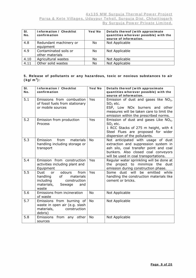
4.10 Agricultural wastes No Not Applicable 4.11 Other solid wastes No Not Applicable 5. Release of pollutants or any hazardous, toxic or noxious substances to air (kg/m3): Sl. No.
Information / Checklist confirmation
Yes/No Details thereof (with approximate quantities wherever possible) with the source of information.
5.1 Emissions from combustion of fossil fuels from stationary or mobile sources
Yes Emission of dust and gases like NO2, SO2 etc. ESP, Low NOx burners and other measures will be taken care to limit the emission within the prescribed norms.
5.2 Emission from production Process
Yes Emission of dust and gases Like NOX, SO2 etc. 1 RCC Stacks of 275 m height, with 4 Steel Flues are proposed for wider dispersion of the pollutants.
5.3 Emission from materials handling including storage or transport
No Not anticipated with usage of dust extraction and suppression system in ash silo, coal transfer point and coal bunkers. Also closed coal conveyors will be used in coal transportations.
5.4 Emission from construction activities including plant and Equipment
Yes Regular water sprinkling will be done at the project to minimize the dust emission during construction phase.
5.5 Dust or odours from handling of materials including construction materials, Sewage and waste
Yes Some dust will be emitted while handling the construction materials like cement or bricks.
5.6 Emissions from incineration of waste
No Not Applicable
5.7 Emissions from burning of waste in open air (e.g. slash materials, construction debris)
No Not Applicable
5.8 Emissions from any other sources
No Not Applicable

4x135 MW Surguja Thermal Power Project Parsa & Kete Villages, Udaypur Tehsil, Surguja Dist. Chhattisgarh
By Surguja Power Private Limited.
Page 10 of 20
6. Generation of Noise and Vibration, and emissions of Light and Heat:
Sl. No.
Information / Checklist confirmation
Yes/No Details thereof (with approximate quantities wherever possible) with the source of information.
6.1 From operation of equipment e.g. engines, ventilation plant, crushers
Yes Noise would be generated generally from steam turbine, generator, compressors, pumps, fans, coal handling plant etc. but all the equipment will be designed and if required acoustic materials will be provided to have the noise level not to exceed the values as stipulated in CPCB/MoEF norms.
6.2 From industrial or similar processes
Yes Noise would be generated from transportation of material / machine.
6.3 From construction or demolition
Yes Some noise would be generated during construction phase but it will be limited to the site only.
6.4 From blasting or piling No Not Applicable 6.5 From construction or
operational traffic Yes During construction and coal
transportation traffic
6.6 From lighting or cooling systems
Yes Indirect process cooling, direct water spraying
6.7 From any other sources No Not Applicable
7. Risks of contamination of land or water from release of pollutants into the ground or into sewers, surface waters, groundwater, coastal waters or the sea: Sl. No.
Information / Checklist confirmation
Yes/No Details thereof (with approximate quantities wherever possible) with the source of information.
7.1 From handling, storage, use or spillage of hazardous materials
No
Not Applicable
7.2 From discharge of sewage or other effluents to water or the land (expected mode and place of discharge)
No Plant will follow the Zero Discharge concept.
7.3 By deposition of pollutants emitted to air into the land or into the water
Yes Installing ESP and other air pollution control equipment will minimize the impact. Similarly COC maximization along with reuse will generate minimum discharge. ETP will be designed to meet stipulated standards. Treated effluent will be reused within the plant. So there will be no significant impact.
7.4 From any other sources No Not Applicable 7.5 Is there a risk of long term
build up of pollutants in the environment from these sources?
Yes Minimum impact on land and water due to state of art technology. The plant will be designed, constructed and operated to maintain all parameters within statutory limits.
4x135 MW Surguja Thermal Power Project Parsa & Kete Villages, Udaypur Tehsil, Surguja Dist. Chhattisgarh
By Surguja Power Private Limited.
Page 11 of 20
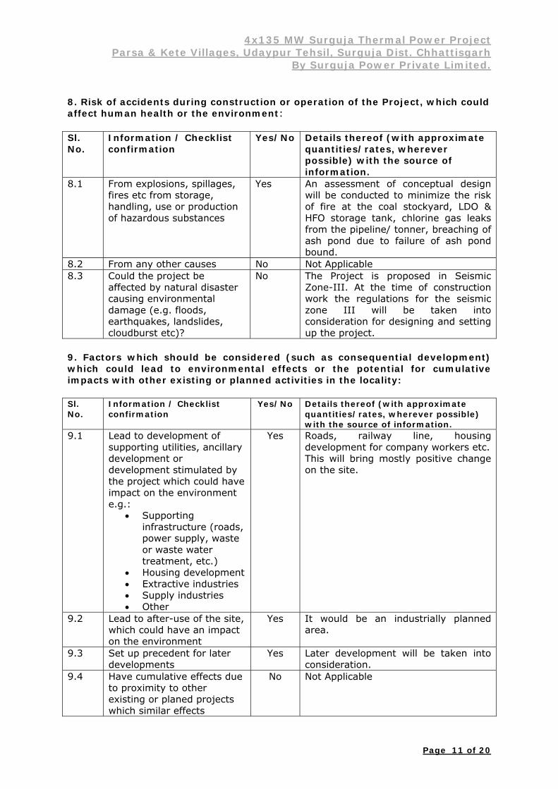
8. Risk of accidents during construction or operation of the Project, which could affect human health or the environment: Sl. No.
Information / Checklist confirmation
Yes/No Details thereof (with approximate quantities/rates, wherever possible) with the source of information.
8.1 From explosions, spillages, fires etc from storage, handling, use or production of hazardous substances
Yes An assessment of conceptual design will be conducted to minimize the risk of fire at the coal stockyard, LDO & HFO storage tank, chlorine gas leaks from the pipeline/ tonner, breaching of ash pond due to failure of ash pond bound.
8.2 From any other causes No Not Applicable 8.3 Could the project be
affected by natural disaster causing environmental damage (e.g. floods, earthquakes, landslides, cloudburst etc)?
No The Project is proposed in Seismic Zone-III. At the time of construction work the regulations for the seismic zone III will be taken into consideration for designing and setting up the project.
9. Factors which should be considered (such as consequential development) which could lead to environmental effects or the potential for cumulative impacts with other existing or planned activities in the locality: Sl. No.
Information / Checklist confirmation
Yes/No Details thereof (with approximate quantities/rates, wherever possible) with the source of information.
9.1 Lead to development of supporting utilities, ancillary development or development stimulated by the project which could have impact on the environment e.g.:
Supporting infrastructure (roads, power supply, waste or waste water treatment, etc.)
Housing development Extractive industries Supply industries Other
Yes Roads, railway line, housing development for company workers etc. This will bring mostly positive change on the site.
9.2 Lead to after-use of the site, which could have an impact on the environment
Yes It would be an industrially planned area.
9.3 Set up precedent for later developments
Yes Later development will be taken into consideration.
9.4 Have cumulative effects due to proximity to other existing or planed projects which similar effects
No Not Applicable

4x135 MW Surguja Thermal Power Project Parsa & Kete Villages, Udaypur Tehsil, Surguja Dist. Chhattisgarh
By Surguja Power Private Limited.
Page 12 of 20
(III) Environmental Sensitivity Sl. No.
Areas Name/ Identity
Aerial distance (within 15 km.) Proposed project location boundary.
1 Areas protected under international conventions, national or local legislation for their ecological landscape, cultural or other related value
None No ecological sensitive zone except Protected Forests and Reserve Forests.
2 Areas which are important or sensitive for ecological reasons – Wetlands, watercourses or other water bodies, coastal zone, biospheres, mountains, forests
None Only Protected Forests and Reserve Forests within 10 km radius of area.
3 Areas used by protected, important or sensitive species of flora and fauna for breeding, nesting, foraging, resting, over wintering, migration
None No ecological sensitive zone except Protected Forests and Reserve Forests.
4 Inland, coastal, marine or underground waters
Atem River
4.0 km
5 State, National boundaries None Not Applicable 6 Routes or facilities used by
the public for access to recreation or other tourist, pilgrim areas
None No tourist or heritage site within 10 Km radius.
7 Defense installations None Not Applicable 8 Densely populated or built-up
area None No major cities within 10 km radius
9 Areas occupied by sensitive man-made land uses (hospitals, schools, places of worship, community facilities)
None Not Applicable
10 Areas containing important, high quality or scarce resources (ground water resources, surface resources, forestry, agriculture, fisheries, tourism, minerals)
None Only Protected Forests and Reserve Forests within 10 km radius from the site.
11 Areas already subjected to pollution or environmental damage. (Those where existing legal environmental standards are exceeded)
None Not Applicable
12 Areas susceptible to natural hazard which cause the project to present environmental problems (earthquakes, subsidence, landslides, erosion, flooding or extreme or adverse climatic conditions)
None The site comes under the Seismic Zone III. Therefore, consideration will be taken care during design and construction stages.

4x135 MW Surguja Thermal Power Project Parsa & Kete Villages, Udaypur Tehsil, Surguja Dist. Chhattisgarh
By Surguja Power Private Limited.
Page 14 of 20
(IV) Proposed Terms of Reference for EIA Studies
Project Proposed 540 (4x135) MW Coal Washery Reject based Thermal Power Project
Category A [1(d) Thermal Power Plant 500 MW]
Project Proponent Surguja Power Private Limited
Location Village Parsa & Kete, Tehsil- Udaypur, District- Surguja, State- Chhatisgarh
INTRODUCTION
540 (4x135) MW Surguja Thermal Power Project in Surguja district of Chhattisgarh is proposed to be set up by Surguja Power Private Limited a fully owned subsidiary of Adani Mining Private Limited. The project is being taken up to meet power requirements of Chhattisgarh. The project is envisaged to be completed during the 12th Plan period between 2012-2017.
The station would require about 4 MMTPA (PLF @ 75%) of Domestic Thermal Coal and Coal Washery Reject considering the installed capacity as 540 MW. The coal from the washery will be transported through conveyor system.
The water requirement of proposed station will be to the tune of 14.14 MCM per year (approx.). Water is proposed to be drawn from the Atem / Rehar River.
The power generated from the project shall be shared between Chhattisgarh and nearby Grid. The provisions for Power evacuation as considered presently shall be reviewed based on the finalized Associated Transmission System (ATS) of the project.
EIA METHODOLOGY
The EIA Report will address all the terms of reference and will be prepared in accordance to the Environment Protection Act 1986 and EIA Notification published by Ministry of Environment and Forests, Govt. of India on 14th September 2006. It will form part of the application to the Statutory Authority. The scope of the EIA Report for the proposed Power Plant includes identifying relevant environmental concerns and focus on potential impacts that may have changed due to the setting up of the plant. The report will also provide an Environment Management Plan and Disaster Management Plan.
The Winter Season, 2011-12 baseline monitoring is being carried out as per the requirement of MoEF.
SITE & STUDY AREA
The proposed 540 (4x135) MW Power Project will be within the Parsa East & Kente Basan Coal Mining Project. Nearest Water source is river Atem / Rehar, which is about 4 / 26 Km from the proposed site. The nearest Railway station is Ambikapur which is approx 60 Km from site.

4x135 MW Surguja Thermal Power Project Parsa & Kete Villages, Udaypur Tehsil, Surguja Dist. Chhattisgarh
By Surguja Power Private Limited.
Page 15 of 20
PROJECT DESCRIPTION
Project Rationale
This section will highlight the goals and objectives of the proposed project. It will also include discussion on the significance of the project in terms of the need for the project in the local as well as the national level, it will also highlight the proposed project in line with existing development plans of the State and Central government and in accordance with the existing or envisioned land use plans.
Project Location
This section will discuss the geographic location of the project. The location of the project will clearly define geographical features (e.g. watersheds, national parks / protected areas, military reservations, etc.) and the general access to the project site (e.g. presence of existing road networks, feeder roads, etc.).

4x135 MW Surguja Thermal Power Project Parsa & Kete Villages, Udaypur Tehsil, Surguja Dist. Chhattisgarh
By Surguja Power Private Limited.
Page 16 of 20
Project Information / Process Information
This portion will include the following
Statement of the Official name of the project and name/s of proponents (including address, telephone nos., etc.) responsible / liable;
Vicinity Plan, Processes involved, Site layout, water balance diagram Project cost and area Resource / Manpower requirements Time frame for project implementation
Process Description
The technology to be used for the project and the process components of the project focusing on the materials input and output from the process components including products, fuels, feedstock and utility requirements (gas, electricity, steam and cooling water will be provided. Material balances (also energy balance); flow diagrams and descriptions of the process to be used will also be provided. The process emissions including air, liquid, and associated wastes, and associated pollution abatement equipment will be discussed.
Pre-Construction
This section shall discuss / describe the various components of the projects. This section shall also discuss the major activities to be undertaken during the construction phase, which shall include but not be limited to:
Site mobilization Road construction / improvement Camp construction Site clearing Construction of the major facilities / project components Construction of support services e.g. Water & Power supply &
Telecommunications, etc.
Operation
This section shall discuss the activities to be undertaken during the operation, which shall include but not limited to:
Major maintenance activities Manpower requirements Fuel Requirement Energy requirements
BASELINE ENVIRONMENTAL SCENARIO
Description of the existing environment, assessment of historical trends of environmental data specific to the proposed site and description of the socio-economic setting in the area will provide an overall picture of the proposed site before any development activities are undertaken. Thus, equipped with the knowledge of the existing environment and aware of the specifications of the proposed project as described in the preceding sections will be identified and areas of critical importance and impacts of the project can be reliably predicted.
Finally, methodologies used in the data collection (primary data) shall be briefly discussed with the corresponding interpretation of the data obtained. Likewise, ail sources of information (secondary data) shall be identified and appropriately acknowledged.
4x135 MW Surguja Thermal Power Project Parsa & Kete Villages, Udaypur Tehsil, Surguja Dist. Chhattisgarh
By Surguja Power Private Limited.
Page 17 of 20
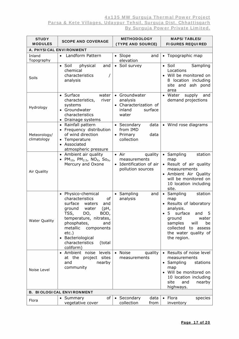
STUDY MODULES SCOPE AND COVERAGE
METHODOLOGY (TYPE AND SOURCE)
MAPS/TABLES/ FIGURES REQUIRED
A. PHYSICAL ENVIRONMENT Inland Topography
Landform Pattern Slope and elevation
Topographic map
Soils
Soil physical and chemical characteristics / analysis
Soil survey Soil Sampling Locations
Will be monitored on 8 location including site and ash pond area
Hydrology
Surface water characteristics, river systems
Groundwater characteristics
Drainage systems
Groundwater analysis
Characterization of inland surface water
Water supply and demand projections
Meteorology/ climatology
Rainfall pattern Frequency distribution
of wind direction Temperature Associated
atmospheric pressure
Secondary data from IMD
Primary data collection
Wind rose diagrams
Air Quality
Ambient air quality PM10, PM2.5, NOX, SoX,
Mercury and Oxone
Air quality measurements
Identification of air pollution sources
Sampling station map
Result of air quality measurements
Ambient Air Quality will be monitored on 10 location including site.
Water Quality
Physico-chemical characteristics of surface waters and ground water (pH, TSS, DO, BOD, temperature, nitrates, phosphates, and metallic components etc.)
Bacteriological characteristics (total coliform)
Sampling and analysis
Sampling station map
Results of laboratory analysis.
5 surface and 5 ground water samples will be collected to assess the water quality of the region.
Noise Level
Ambient noise levels at the project sites and nearby community
Noise quality measurements
Results of noise level measurements
Sampling stations map
Will be monitored on 10 location including site and nearby highways.
B. BIOLOGICAL ENVIRONMENT
Flora Summary of vegetative cover
Secondary data collection from
Flora species inventory

4x135 MW Surguja Thermal Power Project Parsa & Kete Villages, Udaypur Tehsil, Surguja Dist. Chhattisgarh
By Surguja Power Private Limited.
Page 18 of 20
STUDY MODULES SCOPE AND COVERAGE
METHODOLOGY (TYPE AND SOURCE)
MAPS/TABLES/ FIGURES REQUIRED
region forest office
Fauna
Terrestrial fauna including endangered and threatened fauna species
Fauna species inventory survey
Secondary data collection from region forest office
Fauna species inventory
C. SOCIO-ECONOMIC CULTURAL ENVIRONMENT
Demography
Population size Population density,
household size Population by gender Literacy rate Occupation and
employment status
Principal data from Census
Primary Census Abstract
Other Social Services
School facilities Telecommunications,
water and power facilities
Principal data from Census
Village Infrastructure directory
Transportation
Network and mode of transportation
Identification of main and access roads, mode of transportation
Road access map
ASSESSMENT OF ENVIRONMENTAL IMPACTS
There shall be an assessment on feasibility and cost-effective measures to prevent or reduce significant negative environmental impacts identified, to an acceptable level. In this section, the following aspects will be assessed:
The project component and development activities that result in discharges to the environment and the effect of these on the environment
Existing conditions in the site area, including existing land-use, resources and other activities, which in combination with the project activity have potential to affect the environment.
Anticipated environmental effects
This chapter will include appropriate tables and figures to illustrate and summarize the key Information that is relevant in understanding the environmental and socio-economic environment. The environmental and socio-economic impact of the proposed project having regard for regional and cumulative effects will be presented. Wherever possible, the impacts will be quantified. This section will also include measures to address emergency response requirements for accidental events and also estimate costs of those measures and of the institutional training requirements to implement them.
The existing air quality of the region and the impact of the proposed project on regional air quality will be discussed. The component of the project, which will affect air quality, will be identified. All emissions as a result of the proposed projects and their effects on the environment will be discussed. Also the ways and means of reducing the air emissions impact will be discussed.
The project activities that will affect surface water and ground water will be identified. In this section, the water intake requirements during construction, operation and emergency situations will be estimated and the sources will be identified also. Any
4x135 MW Surguja Thermal Power Project Parsa & Kete Villages, Udaypur Tehsil, Surguja Dist. Chhattisgarh
By Surguja Power Private Limited.
Page 19 of 20
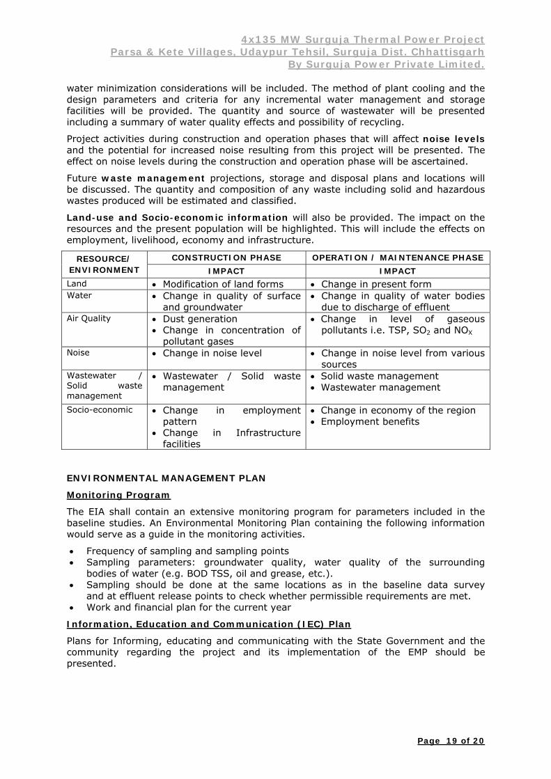
water minimization considerations will be included. The method of plant cooling and the design parameters and criteria for any incremental water management and storage facilities will be provided. The quantity and source of wastewater will be presented including a summary of water quality effects and possibility of recycling.
Project activities during construction and operation phases that will affect noise levels and the potential for increased noise resulting from this project will be presented. The effect on noise levels during the construction and operation phase will be ascertained.
Future waste management projections, storage and disposal plans and locations will be discussed. The quantity and composition of any waste including solid and hazardous wastes produced will be estimated and classified.
Land-use and Socio-economic information will also be provided. The impact on the resources and the present population will be highlighted. This will include the effects on employment, livelihood, economy and infrastructure.
RESOURCE/ ENVIRONMENT
CONSTRUCTION PHASE OPERATION / MAINTENANCE PHASE IMPACT IMPACT
Land Modification of land forms Change in present form Water Change in quality of surface
and groundwater Change in quality of water bodies
due to discharge of effluent Air Quality Dust generation
Change in concentration of pollutant gases
Change in level of gaseous pollutants i.e. TSP, SO2 and NOX
Noise Change in noise level Change in noise level from various sources
Wastewater / Solid waste management
Wastewater / Solid waste management
Solid waste management Wastewater management
Socio-economic Change in employment pattern
Change in Infrastructure facilities
Change in economy of the region Employment benefits
ENVIRONMENTAL MANAGEMENT PLAN
Monitoring Program
The EIA shall contain an extensive monitoring program for parameters included in the baseline studies. An Environmental Monitoring Plan containing the following information would serve as a guide in the monitoring activities.
Frequency of sampling and sampling points Sampling parameters: groundwater quality, water quality of the surrounding
bodies of water (e.g. BOD TSS, oil and grease, etc.). Sampling should be done at the same locations as in the baseline data survey
and at effluent release points to check whether permissible requirements are met. Work and financial plan for the current year
Information, Education and Communication (IEC) Plan
Plans for Informing, educating and communicating with the State Government and the community regarding the project and its implementation of the EMP should be presented.

4x135 MW Surguja Thermal Power Project Parsa & Kete Villages, Udaypur Tehsil, Surguja Dist. Chhattisgarh
By Surguja Power Private Limited.
Page 20 of 20
Contingency / Emergency Response Plan
Procedures on how to cope with emergencies / accidents shall be outlined in a comprehensive contingency / emergency response plan. The institutional responsibilities will be made clear and the flow of communication in cases of emergencies will be included.
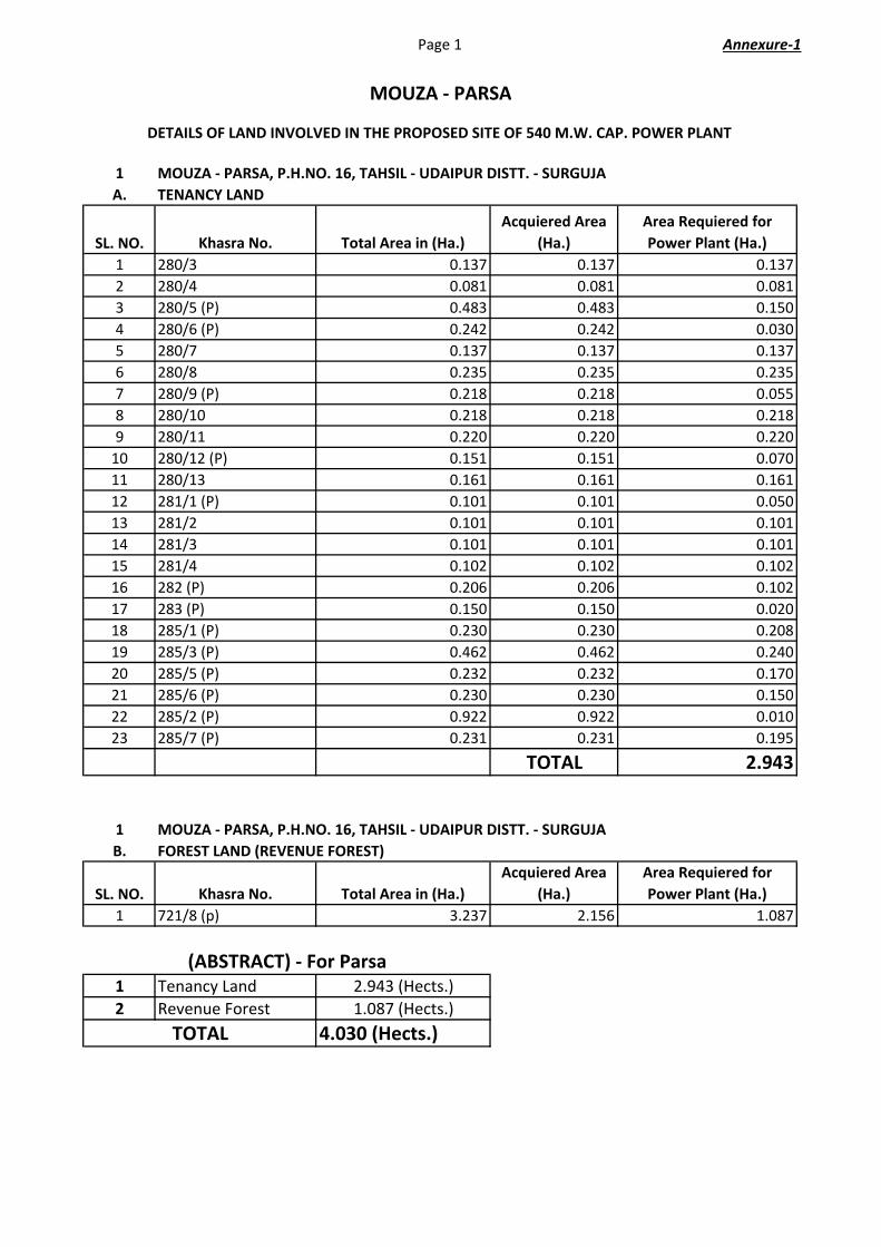
Page 1 Annexure‐1
1
A.
SL. NO. Khasra No. Total Area in (Ha.)
Acquiered Area
(Ha.)
Area Requiered for
Power Plant (Ha.)
1 280/3 0.137 0.137 0.137
2 280/4 0.081 0.081 0.081
3 280/5 (P) 0.483 0.483 0.150
4 280/6 (P) 0.242 0.242 0.030
5 280/7 0.137 0.137 0.137
6 280/8 0.235 0.235 0.235
7 280/9 (P) 0.218 0.218 0.055
8 280/10 0.218 0.218 0.218
9 280/11 0.220 0.220 0.220
10 280/12 (P) 0.151 0.151 0.070
11 280/13 0.161 0.161 0.161
12 281/1 (P) 0.101 0.101 0.050
13 281/2 0.101 0.101 0.101
14 281/3 0.101 0.101 0.101
15 281/4 0.102 0.102 0.102
16 282 (P) 0.206 0.206 0.102
17 283 (P) 0.150 0.150 0.020
18 285/1 (P) 0.230 0.230 0.208
19 285/3 (P) 0.462 0.462 0.240
20 285/5 (P) 0.232 0.232 0.170
21 285/6 (P) 0.230 0.230 0.150
22 285/2 (P) 0.922 0.922 0.010
23 285/7 (P) 0.231 0.231 0.195
TOTAL 2.943
1
B.
SL. NO. Khasra No. Total Area in (Ha.)
Acquiered Area
(Ha.)
Area Requiered for
Power Plant (Ha.)
1 721/8 (p) 3.237 2.156 1.087
1 Tenancy Land 2.943 (Hects.)
2 Revenue Forest 1.087 (Hects.)
4.030 (Hects.)
MOUZA ‐ PARSA
(ABSTRACT) ‐ For Parsa
TOTAL
DETAILS OF LAND INVOLVED IN THE PROPOSED SITE OF 540 M.W. CAP. POWER PLANT
MOUZA ‐ PARSA, P.H.NO. 16, TAHSIL ‐ UDAIPUR DISTT. ‐ SURGUJA
TENANCY LAND
MOUZA ‐ PARSA, P.H.NO. 16, TAHSIL ‐ UDAIPUR DISTT. ‐ SURGUJA
FOREST LAND (REVENUE FOREST)

Page 2 Annexure‐1
2
A.
SL. NO. Khasra No. Total Area in (Ha.)
Acquiered Area
(Ha.)
Area Proposed for Power
Plant (Ha.)
1 `2/1 0.084 0.084 0.084
2 `2/2 0.083 0.083 0.083
3 `2/3 0.084 0.084 0.084
4 3 (p) 0.806 0.806 0.660
5 5/3 (p) 0.186 0.186 0.160
6 8/1 (p) 0.364 0.364 0.101
7 8/2 (p) 0.647 0.647 0.255
8 9 0.543 0.543 0.543
9 10 0.198 0.198 0.198
10 11 0.393 0.393 0.393
11 12 0.061 0.061 0.061
12 `13/1 0.040 0.040 0.040
13 `13/2 0.069 0.069 0.069
14 `14/1 0.106 0.106 0.106
15 `14/2 0.260 0.260 0.260
16 `14/3 0.006 0.006 0.006
17 `17/1 0.320 0.320 0.320
18 `18/1 0.283 0.283 0.283
19 `18/2 0.191 0.191 0.191
20 `18/3 0.049 0.049 0.049
21 `18/4 0.190 0.190 0.190
22 19 0.291 0.291 0.291
23 20 0.061 0.061 0.061
24 21 0.299 0.299 0.299
25 `22/1 0.182 0.182 0.182
26 `22/2 0.214 0.214 0.214
27 `22/3 0.235 0.235 0.235
28 `22/4 0.223 0.223 0.223
29 `22/5 0.056 0.056 0.056
30 `22/6 0.061 0.061 0.061
31 `22/7 0.057 0.057 0.057
32 `24/1` 0.134 0.134 0.134
33 `24/2 0.134 0.134 0.134
34 `24/3 0.133 0.133 0.133
35 `25/3 0.050 0.050 0.050
36 `25/4 0.016 0.016 0.016
37 `25/5 0.017 0.017 0.017
38 `26/1 0.081 0.081 0.081
39 `26/2 0.041 0.041 0.041
40 `26/3 0.040 0.040 0.040
41 `27/1 0.202 0.202 0.202
42 `27/2 (P) 0.203 0.203 0.035
43 `28/2 0.494 0.494 0.494
MOUZA ‐ KETE
MOUZA ‐ KETE, P.H.NO. 16, TAHSIL ‐ UDAIPUR DISTT. ‐ SURGUJA
TENANCY LAND

Page 3 Annexure‐1
SL. NO. Khasra No. Total Area in (Ha.)
Acquiered Area
(Ha.)
Area Proposed for Power
Plant (Ha.)
44 29 (P) 0.081 0.081 0.054
45 `30/1 (P) 0.186 0.186 0.012
46 `30/2 0.182 0.182 0.182
47 `30/3 0.121 0.121 0.121
48 `31/1 (P) 0.129 0.129 0.030
49 `31/2 0.154 0.154 0.154
50 `31/3 0.089 0.089 0.089
51 32 0.081 0.081 0.081
52 33 0.036 0.036 0.036
53 34 0.093 0.093 0.093
54 35 0.020 0.020 0.020
55 36 0.028 0.028 0.028
56 38 (P) 0.020 0.020 0.007
57 40 0.085 0.085 0.085
58 41/1 0.029 0.029 0.029
59 41/2 (P) 0.075 0.075 0.025
60 42 (P) 0.599 0.599 0.120
61 129 0.073 0.073 0.073
62 156/1 0.304 0.304 0.304
63 156/2 (P) 0.303 0.303 0.290
64 157/1 (P) 0.117 0.117 0.105
65 157/2 0.433 0.433 0.433
66 157/3 0.344 0.344 0.344
67 157/4 0.324 0.324 0.324
68 158/1 (P) 1.064 1.064 1.030
69 158/2 (P) 1.064 1.064 0.920
70 159/1 1.445 1.445 1.445
71 159/2 0.186 0.186 0.186
72 159/3 (P) 0.973 0.973 0.580
73 159/4 0.206 0.206 0.206
74 162/2 (P) 0.273 0.273 0.065
Total 14.663
1
B.
SL. NO. Khasra No. Total Area in (Ha.)
Acquiered Area
(Ha.)
Area Requiered for
Power Plant (Ha.)
1 6 (P) 0.458 0.458 0.030
2 16 0.016 0.016 0.016
3 23 0.737 0.737 0.737
4 `28/1 (P) 1.961 1.961 0.137
5 `28/3 0.579 0.579 0.579
6 130/1 0.497 0.497 0.101
7 130/3 0.049 0.049 0.049
TOTAL 1.649
MOUZA ‐ KETE, P.H.NO. 16, TAHSIL ‐ UDAIPUR DISTT. ‐ SURGUJA
FOREST LAND (REVENUE FOREST)

Page 4 Annexure‐1
1
C.
SL. NO. Khasra No. Total Area in (Ha.)
Acquiered Area
(Ha.)
Area Requiered for
Power Plant (Ha.)
1 `1/1 39.916 39.916 27.371
1
D.
SL. NO. Khasra No. Total Area in (Ha.)
Acquiered Area
(Ha.)
Area Requiered for
Power Plant (Ha.)
1 37 (P) 0.049 0.049 0.029
1 Tenancy Land 14.663
2 Govt Revenue Land 0.029
3
Revenue forest
(Chhote Jhar/Bade
Jhar) 1.649
4 Protected Forest 27.108
Total 43.449
(ABSTRACT) for Kete
MOUZA ‐ KETE, P.H.NO. 16, TAHSIL ‐ UDAIPUR DISTT. ‐ SURGUJA
PROTECTED FOREST (Compartment No. P ‐ 2008, Gumga Block, Range ‐ Udaipur,
Division ‐ South surguja
MOUZA ‐ KETE, P.H.NO. 16, TAHSIL ‐ UDAIPUR DISTT. ‐ SURGUJA
GOVT. LAND
SurgujaPowerPrivateLimited.
FEASIBILITYREPORT
4x135MW,SURGUJATHERMALPOWERPROJECT
Developer:
SURGUJAPOWERPRIVATELIMITEDDOC.NO.:SPPL/THERMAL/CHHATTISGARH/FR/R2February‐2013
FeasibilityReport
4x135MWThermalPowerPlant SurgujaPowerPvt.Ltd
Doc. No.: SPPL/THERMAL/CHHATTISGARH/FR/R1 i
1.EXECUTIVESUMMARY:AdaniGroup,aUS$6billioncompanybasedinAhmedabad, isoneoftheBusinessHouseofthecountrywithdiverseinterestinglobaltrading,developmentandoperationofPorts,IDCterminal,establishment of SEZ, Oil refining, logistics, gas distribution, Power Generation, PowerTransmissionandPowerTradingetc.AdaniGrouphas embarked thebusiness opportunity in coalmining sector and for the purposecreatedaSPVviz.AdaniMiningPrivateLimited(AMPL).TheGrouphavealreadycommencedcoalminingoperationsinIndonesia.AdaniPowerLimited,asubsidiaryofAdaniEnterprisesLimited,isdevelopingnumberofPowerProjectsalongwith its associateddedicated transmission systems.Presently,AdaniPowerLimitedissettingupa4620MWMundraThermalPowerStation(StageI:660MW,StageII:660MW,StageIII:1320MW,Stage‐IV:1980MW)inGujarat,3300MW(StageI:2x660MW,StageII:1x660MW,StageIII:2x660MW)TirodaPowerStationinMaharashtraand1320 MW Coal based Power Project at Kawai in Rajasthan. Besides, Adani Power Ltd is alsoplanning todevelop2640MWCoalBasedPowerProjectatDahej inGujaratand1320MWCoalbasedPowerProjectatChhindwarainMadhyaPradesh.SurgujaPowerPrivateLimited(SPPL),a100%subsidiaryofAdaniMiningPrivateLimited(AMPL)isplanningtosetupa540MW(4x135MW)ThermalPowerProjectbasedontheCoalWasheryRejectsnear theParsaEastCoalBlockatUdaypurTehsil, SurgujaDist,Chhattisgarh.TheGrouphas been assigned work by Rajathan Rajya Vidyut Utpadan Nigam Ltd (RRVUNL) for Mining,Development and Operation of Parsa East Coal Block and supply of beneficiated coal, havingguaranteedcalorificvalue.Sizablerejectcoalwillbegenerated,whichshallbeutilisedforPowerGenerationbysettingupPowerProjectinthevicinityofthecoalblock,soastominimiseimpactontheenvironment.Accordingly,theCompanyproposestosetup540MW(4x135MW)PowerProject(CFBCTechnologyforBoilers)neartheParsaEastCoalBlockforwhichthecompanyhasenteredintoanMOUwiththeGovernmentofChhattisgarh.Theannualcoalrequirement(washeryrejects+linkagecoal)wouldbearound4MMTPAfortheproject.Thecoalrejectswouldbesourced fromtheproposedcoalwasheryprojectbeingsetupneartheParsaEastCoalBlockandnearbycoalwasheryprojectsandadditionalwashedcoalshallbesourcedfromallocatedlinkage/mines.As per the Electricity Act 2003, any Generating Companymay Establish, Operate andMaintainPowerGeneratingStation. Theproposed540MW(4x135MW)Thermalpower stationwouldrequireabout47.5Hectaresoflandandwouldrequirearound39.284MLDofwaterand4millionmetrictonnesofcoal(washeryrejects+linkagecoal)perannumforaplantloadfactor(PLF)ofaround75%. Theprojectwillbe financedsuchthat thecapitalstructure isbuiltup toequitycapital30%andloan capital 70%. The Project Cost with Interest during Construction (IDC) and pre‐operativeexpensesisestimatedasRs.3,500crores.ItisproposedtohaveaEnvironmentFriendlyCirculatingFluidizedBedCombustion(CFBC)basedcoal firedboilers,multi‐cylinderheatcondensing turbinesandaircooledgeneratorsof135MWMCReachwithbrushlessorstaticexcitationsystemaspermanufacturesstandard.Thestate‐of‐the‐arttechnologywillbedeployedforauxiliariesandsub‐systemstoensuresafeandcontinuousoperationoftheunitswithminimumunscheduledoutages.

FeasibilityReport
4x135MWThermalPowerPlant SurgujaPowerPvt.Ltd
Doc. No.: SPPL/THERMAL/CHHATTISGARH/FR/R1 ii
Therejectcoal for theplantwillbe transportedbydedicatedconveyorsystemandwashedcoalshallbetransportedbyrail/road.Thecoalhandlingsystemoftheproposedgeneratingunitswillhavethecapacityof1600TPH.Thecoalstorageof15daysforblendingcoaland7daysstorageforwasheryrejectsshallbekeptinplant.Singlestagecrushing,stacking,reclaiming&feedingsystemwillbeprovided. Dryextractionanddisposalsystemisbeingconsideredforbottomashandflyashforthestation.AshutilizationwillbeasperMOEFguidelines.Itisproposedtouseashtotheextentpossibleformanufacturingofcement,buildingmaterial,roadconstructionetc.ortofillminevoids.ThecondensercoolingshallbeinclosedcircuitcoolingsystemwithInducedDraftCoolingTowers(IDCT)usingmakeupwaterfromAtem/Reharriver.The proposed electrical system will be equipped with adequately sized equipments and withgenerousredundancytoensureuninterruptedoperationoftheplant.A400kVswitchyardwillbeprovided for the evacuation of power with required nos. of out going feeders. The exactconfigurationwouldbedecidedafter tyingup thepowerevacuationwith thepurchaserandthereceivingsubstationvoltagelevel.The proposed station envisages the state‐of‐the‐art Distributed Digital Control & ManagementInformation System (DDCMIS)whichwill integrate various closed loop sub‐systems, open loopsub‐systems,monitoringand informationsub‐systemcovering theentireplant. Thesystemwillalsointegratethevariousproprietarycontrolpackagessuppliedbythemainequipmentvendorsforharmoniousplantoperation.To minimize emission of Suspended Particulate Matter (SPM) along with boiler flue gases,ElectrostaticPrecipitatorsofhighefficiencyandadequatesizewillbeprovidedatexitendofeachboilertobringdownSPMemissionlevelunder50mg/Nm3.One(1)numberquadrupleflue275mhigh stack is envisaged for theproposedunits. Liquidwaste from theplantwill beproperlytreatedbeforere‐useand/ordisposal.Adequatefacilitieswillbedevelopedforexecutionoftheproject.TheprojectwillbeimplementedonEngineering,ProcurementandConstruction(EPC)concept.Thescheduleofcommissioningof firstunits isenvisagedas27monthsandthereaftereachunitshallbecommissionedwithinanintervalof3monthseach.

FeasibilityReport
4x135MWThermalPowerPlant SurgujaPowerPvt.Ltd
Doc. No.: SPPL/THERMAL/CHHATTISGARH/FR/R1 iii
SALIENTFEATURES
1.01.00 LOCATION:Thesiteissituatedabout70.0KmSouth‐WestofAmbikapurrailway
stationofSouthEasternRailway.Thesiteisatadistanceof290Kmbyroadfrom
Raipur, the state capital of Chhattisgarh. The proposed site iswell connected by
roads from all sides. An existing two lane state highway from Ambikapur to
Bilaspurispassingatabout7kmfromproposedsite.
1.02.00 LAND:Theprojectisplannedtobeaccommodatedwithin47.5Hectaresofland
1.03.00 CAPACITY:540MW–(4x135MW)
1.04.00 MODEOFOPERATION:BaseLoad
1.05.00 FUEL:WasheryRejects&linkageCoal
1.06.00 COAL:Coalrequirementof4MMTPA(at75%PLF)
1.07.00 COALTRANSPORTATION:ThecoalminesofEastblockofParsaCoalFieldshas
beenconsideredasthemainsourceofcoal.WasheryrejectsfromCoalfieldsshall
betransportedtothepowerplantbydedicatedBeltConveyors.
Coal for blending shall be transported by Rail/Road from the allotted
mines/linkage.
1.08.00 COOLINGWATER:Makeupwater requirement for theprojectwouldbe about
39.284mld. Identifiedsourceofwateris fromRiverAtem/Reharnear
proposedsite.
1.09.00 STEAMGENERATORTECHNOLOGY:TheSteamGenerators(SG)shallbeof
CFBCsubcritical, single/doublepass (tower type/twopass type), single reheat,
radiant furnace, dry bottom, balanced draft, outdoor type, coal fired with all
necessaryauxiliaries.
1.10.00 POWEREVACUATIONSYSTEM:PowergeneratedfromtheproposedProject
shall be stepped upto 400 kV and will be evacuated by PGCL and/or CSEB’s
TransmissionNetwork.
1.11.00 BENEFICIARY: It isenvisaged that thepowergenerated fromtheprojectshall

FeasibilityReport
4x135MWThermalPowerPlant SurgujaPowerPvt.Ltd
Doc. No.: SPPL/THERMAL/CHHATTISGARH/FR/R1 iv
beabsorbedbyChhattisgarhandotherstates.
1.12.00 ENVIRONMENTAL ASPECTS: Necessary regulatory clearances from State
PollutionControlBoardandMinistryofEnvironment&Forestswillbeobtained.
ThiswillbeinaccordancewiththeprocedureslaiddownintheEIANotification
dated. 14th September, 2006. Environmental ImpactAssessmentReportwill
be prepared and State Pollution Control Board will be approached for
conductingPublicHearing.Provisionshallbemade fordry flyashextraction.
Flyashextractedindryformshallbetransportedtoastoragesiloandshallbe
giventotheuserforashutilizationactivities.
1.13.00 COMMISSIONINGSCHEDULE: The commercial operation of the First unit
willcommencein27monthsfromNoticetoProceed(NTP)toEPCContractor
andsubsequentunitsatanintervalof3months.
1.14.00 PROJECTFINANCING:Debtequity ratioshallbe70:30.Equityportionshall
bemetfromthepromoter'scontributionsandthedebtportionisproposedto
bearrangedthroughcommercialborrowings/bonds.
1.15.00 PROJECTCOST:
CostEstimates:
Theproject is proposed to be set up at an aggregate cost ofRs. 3,500 crorescomprising of expenditure towards land, EPC cost, water, Township, Coaltransportation cost, transmission line, preliminary and pre‐operativeexpenditure,contingencies,InterestduringConstructionandMarginMoneyforworkingCapital.
AsummaryofcomponentsofProjectCostisgivenbelow:
ParticularEstimatedCost(Rs.inCrores)
Land&SiteDevelopment 20
Engineering,Procurement&ConstructionCost 2750
Township 35
WaterArrangement 15
CoalSupplyArrangement 30
TransmissionLine 150
TotalHardCost 3000
Pre‐operativeExpenditure 60

FeasibilityReport
4x135MWThermalPowerPlant SurgujaPowerPvt.Ltd
Doc. No.: SPPL/THERMAL/CHHATTISGARH/FR/R1 v
InterestDuringConstructionPeriod 285
Contingencies 65
MarginMoneyforworkingcapital 90
TotalCost 3500
6.2 FinancingStructure:
TheProjectcostisestimatedatRs.3500Crore&isproposedtobefinancewithseniordebt,subdebt&equityinratioof70:30.Theproposedcomponentsoffinancingare:
Particular Rs.inCrores %
CapitalContribution–Equity 1050.00 30
SeniorDebtFinance 2450.00 70
Total 3500.00 100
6.3 InterestduringConstructionPeriod:
Theinterestduringconstruction(IDC)periodestimatedatRs.285Crorehasbeencalculatedassuminganimplementationperiodof27monthsforthefirstunitandthereaftereachunitshallbecommissionedwithinanintervalof3monthseachforthefourthunitfromNoticetoProceed(NTP)toEPCcontractor.
6.4 WorkingCapital:
The provision for margin money for working capital has been made at Rs. 90Crore.
FeasibilityReport
4x135MWThermalPowerPlant SurgujaPowerPvt.Ltd
Doc. No.: SPPL/THERMAL/CHHATTISGARH/FR/R1 vi
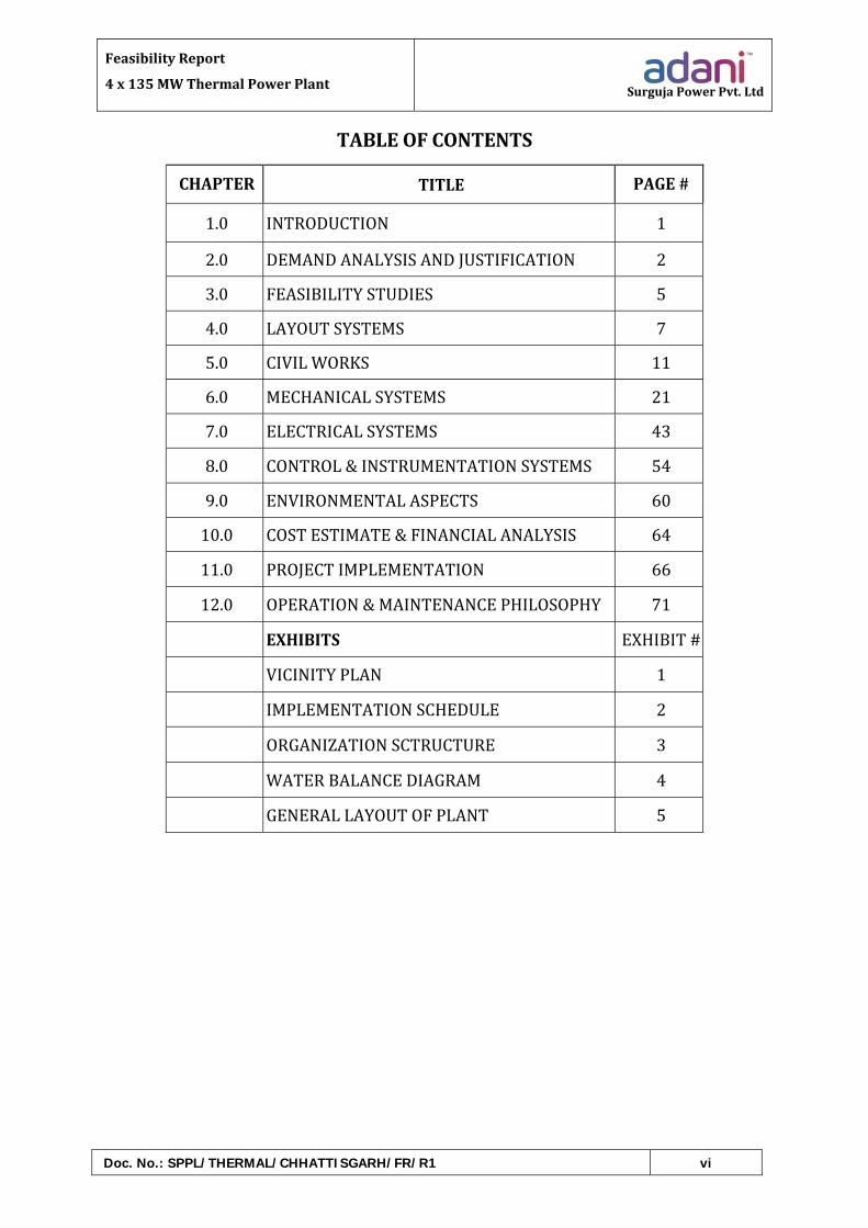
TABLEOFCONTENTS
CHAPTER TITLE PAGE#
1.0 INTRODUCTION 1
2.0 DEMANDANALYSISANDJUSTIFICATION 2
3.0 FEASIBILITYSTUDIES 5
4.0 LAYOUTSYSTEMS 7
5.0 CIVILWORKS 11
6.0 MECHANICALSYSTEMS 21
7.0 ELECTRICALSYSTEMS 43
8.0 CONTROL&INSTRUMENTATIONSYSTEMS 54
9.0 ENVIRONMENTALASPECTS 60
10.0 COSTESTIMATE&FINANCIALANALYSIS 64
11.0 PROJECTIMPLEMENTATION 66
12.0 OPERATION&MAINTENANCEPHILOSOPHY 71
EXHIBITS EXHIBIT#
VICINITYPLAN 1
IMPLEMENTATIONSCHEDULE 2
ORGANIZATIONSCTRUCTURE 3
WATERBALANCEDIAGRAM 4
GENERALLAYOUTOFPLANT 5
FeasibilityReport
4x135MWThermalPowerPlant SurgujaPowerPvt.Ltd
Doc. No.: SPPL/THERMAL/CHHATTISGARH/FR/R2 Page 1 of 82
INTRODUCTION
1.00.00 BACKGROUND
Power development is one of the key infrastructural elements for theeconomic development of the country. In recent years, power developmenthasassumedparamountimportanceinviewofitsroleinrapiddevelopmentof industry, agriculture and service sector in the country. The installedcapacityofthecountrywasonly1713MWin1950buthasalreadygrowntoaround2,11,766MWasperlatestreportsofpowerministry.
Evenafterconsiderablecapacityaddition inrecentyearsourcountry facesapeak power deficit of about 9%, which leads to Load Shedding to theIndustrialSectorleadingtohugelossofproductivity.
2.00.00 PROPOSAL
The present proposal is to implement 540 MW Coal Based Thermal PowerProject at ParsaEastBlock,UdaypurTehsil, Surguja:Dist, Chhattisgarh State.Basicinputslikecoal,land,wateretcwillbetiedupwithGovt.ofChhattisgarhandMinistryofCoal,GOI.

FeasibilityReport
4x135MWThermalPowerPlant SurgujaPowerPvt.Ltd
Doc. No.: SPPL/THERMAL/CHHATTISGARH/FR/R2 Page 2 of 82
DEMANDANALYSISANDJUSTIFICATION
1.00.00 GENERAL:
A 4 x 135 MW Surguja Thermal Power Project, in Surguja district ofChhattisgarhwillbetakenupbyM/sSurgujaPowerPrivateLimiteda100%subsidiary ofM/sAdaniMining Pvt. Limited,which is a fully owned byM/sAdani Enterprises Limited. The project is being taken up to meet powerrequirements of Chhattisgarh, western region & India. The project isenvisagedtobecompletedduringthe12thPlanperiod.
2.00.00 PRESENTSTATUSOFDEMAND&AVAILABILITY:
Thereviewofthestatisticsrevealsthatthereisanenergyshortagetothetuneof8.8%all‐Indiabasis in theperiodApr‐Dec2010.Notably there isanacuteshortageinthecertainareasofthecountry.
Thepeakdemandshortageonall‐Indiabasisforthisperiodwasnearly9981MW.Itmaybenotedthatthepeakdemandisactuallyrestricteddemandandislikelytobemuchhigher.
Keepingthepresentscenarioofshortagesinenergyandpeakdemandinviewand tomaintain a GDP (GrossDomestic Product) growth of 8% to 10%, theGovernmentofIndiahasveryprudentlysetatargetofabout212,000MWofpowergenerationcapacitybyMarch,2012.
3.00.00 THEPOWERSCENARIOINCHHATTISGARH:
AsperLoadGenerationBalanceReportfortheyear2012‐13,releasedbyCentral Electricity Authority, Ministry of Power, Government of India,comparisonofpresentinstalledcapacityinthestate,regionandallIndialevelandPeakDemandSupplyGapareindicatedinbelowmentionedtable;
PresentInstalledCapacity
Sr.No Description Unit Chhattisgarh Western
Region AllIndia
1 Hydel MW 120.00 7447.50 37416.40
2 Coalbased MW 5175.94 43537.00 121610.88
3 Gasbased MW 0.00 8254.81 18903.05
4 Dieselbased MW 0.00 17.48 1199.75
5 Renewableenergy MW 281.15 8450.04 25856.14
6 Nuclear MW 47.52 1840.00 4780.00
7 Total MW 5624.61 69546.83 211766.22

FeasibilityReport
4x135MWThermalPowerPlant SurgujaPowerPvt.Ltd
Doc. No.: SPPL/THERMAL/CHHATTISGARH/FR/R2 Page 3 of 82
(ason31.01.2013)
EnergyRequirementv/sAvailability(2011‐12)(Annex‐IIoftheLGBR2012‐13)
Sr.No.
Parameters Energy
RequirementEnergy
Availability
PeakDeficit/Surplus
PeakDeficit/Surplus
Region MU MU MU %
1 Chhattisgarh 15,013 14,615 ‐398 ‐2.7
2 WesternRegion 2,90,421 2,57,403 ‐33,018 ‐11.4
3 AllIndia 9,37,199 8,57,886 ‐79,313 ‐8.5
PeakDemandSupplyGap(2011‐12)(Annex‐IIIoftheLGBR2012‐13)
Sr.No.
Parameters Peak
DemandPeak
Availability
PeakDeficit/Surplus
PeakDeficit/Surplus
Region MW MW MW %
1 Chhattisgarh 3,239 3,093 ‐146 ‐4.5
2 WesternRegion 42,352 36,509 ‐5,843 ‐13.8
3 AllIndia 1,30,006 1,16,191 ‐13,815 ‐10.6
FromtheabovetablesitisevidentthatasubstantialquantityofpowerisrequiredtomeetthepeakdemandintheStateofChhattisgarhaswellasotherregionsofIndia. With the availability of required infrastructure facilities, the State ofChhattisgarhhasthepotentialtogrowasapowerhubinthecountry.
Inconclusionitcanbestatedthatthegapbetweenavailabilityofpowerandthedemand is not likely to be closed in the foreseeable future either in westernregion or in Chhattisgarh state unless all out efforts are made to add capacityconsideringthefuelavailabilityandevacuation.
Themajoradvantage inplanning theproposedThermalPowerPlant inSurgujadistrictmaybesummarizedbelow:
Sufficient land is already available for installationof theproposedpowerplant.Land acquisition would not pose any problem with minimum Relocation &Rehabilitation.
Siteiswellconnectedbyroad. Nearestrailhead(B.G)atAmbikapuriswithin70Kmfromproposedsite.
FeasibilityReport
4x135MWThermalPowerPlant SurgujaPowerPvt.Ltd
Doc. No.: SPPL/THERMAL/CHHATTISGARH/FR/R2 Page 4 of 82
WaterrequiredforthestationcanbeassuredfromnearbyriversAtem/Rehar AnumberofTransmissionnetworksofbothStateGridandPGCILareavailable
withinreasonabledistance. ThelocationofproposedSiteisnearbyCoalminesreducingcoallogisticscost.
TheUnitratingandplantlocationwillmeettheoperationalrequirementsoftheproject. The plant concept and the technical features of the selected plant andequipmentarestandardandproven.The "low cost of power" would prove to be the strong point of this projectwheneverthefullcompetitionwouldbeunleashedinthepowersectorinthenearfuture.
FeasibilityReport
4x135MWThermalPowerPlant SurgujaPowerPvt.Ltd
Doc. No.: SPPL/THERMAL/CHHATTISGARH/FR/R2 Page 5 of 82
FEASIBILITYSTUDIES
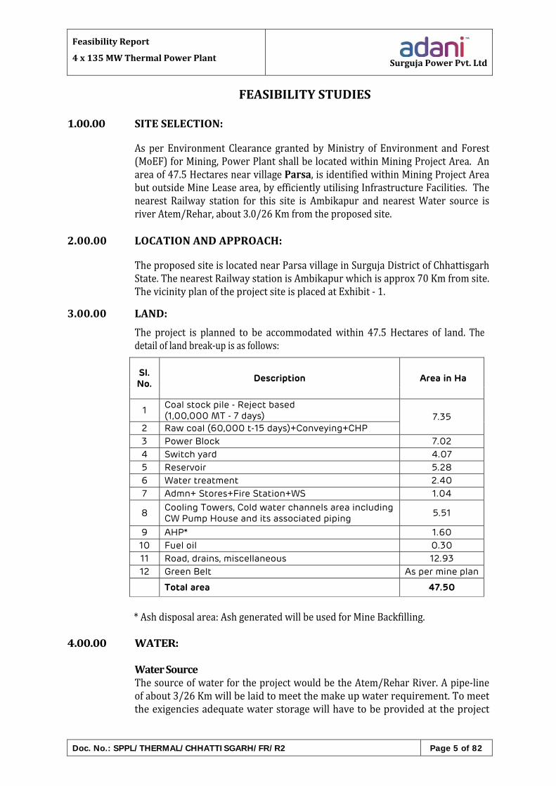
1.00.00 SITESELECTION:
As per Environment Clearance granted byMinistry of Environment and Forest(MoEF)forMining,PowerPlantshallbelocatedwithinMiningProjectArea.Anareaof47.5HectaresnearvillageParsa,isidentifiedwithinMiningProjectAreabutoutsideMineLeasearea,byefficientlyutilisingInfrastructureFacilities.Thenearest Railway station for this site is Ambikapur and nearestWater source isriverAtem/Rehar,about3.0/26Kmfromtheproposedsite.
2.00.00 LOCATIONANDAPPROACH:
TheproposedsiteislocatednearParsavillageinSurgujaDistrictofChhattisgarhState.ThenearestRailwaystationisAmbikapurwhichisapprox70Kmfromsite.ThevicinityplanoftheprojectsiteisplacedatExhibit‐1.
3.00.00 LAND:
The project is planned to be accommodatedwithin 47.5 Hectares of land. Thedetailoflandbreak‐upisasfollows:
Sl. No.
Description Area in Ha
1 Coal stock pile - Reject based (1,00,000 MT - 7 days) 7.35
2 Raw coal (60,000 t-15 days)+Conveying+CHP
3 Power Block 7.02
4 Switch yard 4.07
5 Reservoir 5.28
6 Water treatment 2.40
7 Admn+ Stores+Fire Station+WS 1.04
8 Cooling Towers, Cold water channels area including CW Pump House and its associated piping
5.51
9 AHP* 1.60
10 Fuel oil 0.30
11 Road, drains, miscellaneous 12.93
12 Green Belt As per mine plan
Total area 47.50
*Ashdisposalarea:AshgeneratedwillbeusedforMineBackfilling.
4.00.00 WATER:
WaterSourceThesourceofwaterfortheprojectwouldbetheAtem/ReharRiver.Apipe‐lineofabout3/26Kmwillbelaidtomeetthemakeupwaterrequirement.Tomeettheexigenciesadequatewaterstoragewillhavetobeprovidedattheproject

FeasibilityReport
4x135MWThermalPowerPlant SurgujaPowerPvt.Ltd
Doc. No.: SPPL/THERMAL/CHHATTISGARH/FR/R2 Page 6 of 82
site.WaterRequirementandCommitment:Make up water requirement for the project (4X135 MW) would be about39.284 MLD (14.14 MCMPA). As per current water study report ofAtem/ReharRiverbasin,sufficientwaterisavailabletocatertheneedofthe540MWProjectatSurguja.
5.00.00 COALREQUIREMENT:
CoalWasheryrejectsRequirementandAvailability:
The CoalWashery Rejects from the proposed coalwashery plantwill haveGCVof2,000Kcal/Kgandashcontentofabout58%.TheCoalwasheryrejectsrequirementwill be about 4MMTPA (corresponding to 75%PLF). Projectdeveloper has applied to concernedAuthorities for long term coal linkageforthecleancoaltoblendwiththecoalwasheryrejects.
CoalTransportation:
Coal(washeryrejects)wouldbetransportedfromCoalwasheryplanttothepower station through Belt Conveyors. Clean Coal shall be transported topowerstationbyrail/road.
CoalQuality:
ThecoalqualityconsideredforFRisasfollows:Ash : 50‐59%GGV(kcal/kg) : 1850‐2300Kcal/KgTotalMoisture : 12‐15%
6.00.00 RAILWAYSIDING:
The railwaysidingbeingdevelopedbySurgujaRailCorridorPrivateLimitedforTransportationofwashedcoalwillbeutilisedforbringingthelinkagecoal,ifrequired,forblendingwiththecoalwasheryrejects.
7.00.00 CONSTRUCTIONWATER: A water pipeline of about 3/26 km (depending upon intake from Atem or
ReharRiver)withsuitablediameterwillbelaidfromintakepointtoProjectsite.
8.00.00 CONSTRUCTIONPOWER:
TherequirementsoftheconstructionpowersupplyfortheprojectwouldbemetfromthenearestCSEB/PGCILsubstation.

FeasibilityReport
4x135MWThermalPowerPlant SurgujaPowerPvt.Ltd
Doc. No.: SPPL/THERMAL/CHHATTISGARH/FR/R2 Page 7 of 82
LAYOUTSYSTEMS
1.00.00 GENERALLAYOUTPLAN:
The General Layout Plan for the project has been developed taking intoconsideration the various aspects like land acquisition, ground features, groundcontours, villages in the vicinity, corridor for outgoing transmission lines,road/rail approaches, prevailing wind direction, location of raw water intakepump‐houseandassociatedpipecorridors.Accordingly,theswitchyardhasbeenplannedtofacetowardsNorth.
The main power house is expanding from west to east with other permanentfacilitieslikeservicebuilding,workshop,O&Mstoresetclocatedtowardsthewestofthemainplant,keepingtheexpansionsidefreeforconstructionactivities.Theintake/discharge ducts have been routed in the corridor between transformeryardandtheswitchyard.Twonos.ofCWPHforatotaloffourunitsareenvisagedonthesouthsideofPowerblock.One(1)no.singlestackquadfluechimneyhasbeenplanned.
The Induced draft cooling towers for the project are appropriately locatedconsidering their safe distance from the switchyard and the main plant. ThewatertreatmentplantandtheDMwaterfacilitiesare locatedonSouthernmostpartofarea.
The Coal Handling Plant (CHP) and the coal stockyard for the plant are locatedtowards North‐West side of the main plant, considering the washery rejecttransportationfromWestandlinkagecoal fromNorthside, thusminimizingthecostoftheCHPworks.
Adequate space provision has been kept in the layout for lay‐down and pre‐assemblyactivities,openstores,contractor'sofficesandstoresetc.Constructionoffices and storage sheds are located close to the main approach road to theplant.AdministrationBuildingisproposedtobelocatednearthemainapproachroad.
Rawwaterreservoirfor15dayswaterrequirementhasbeenprovidedtowardsSouth‐Westofmainplant.
Greenbelthasbeenprovidedallalongtheperipheryoftheplantboundary.Spacehasalsobeenkeptoutsidetheplantboundaryfordiversionofexistingroadsanddrains.
2.00.00 INTRODUCTION:
2.01.00 The main plant building arrangement for the proposed stage of the plantenvisages longitudinal disposition of TG set. Themain power housewill be260mwideandabout270mlongconsistingofTGbayandheaterbay.Arailcum road is provided along "A" row for handling generator stator andtransformers.
Service Building is envisaged at the start of unit # 1 for this phase of the

FeasibilityReport
4x135MWThermalPowerPlant SurgujaPowerPvt.Ltd
Doc. No.: SPPL/THERMAL/CHHATTISGARH/FR/R2 Page 8 of 82
project. An interconnection walkway is also provided between Service cumControlRoomBuilding andoperating floor level inABbay formovement ofpersonnel.
2.02.00 DESCRIPTIONOFLAYOUT:
2.02.01 MechanicalArea:
ABBay:
ThelayoutenvisagesABbayofwidth32mandfloorsatEL(+/‐)0.00m,(+)6.50m,(+)12.50m.Theoperatingflooroftheunitiskeptat(+)12.50mandthemezzaninefloorisat(+)6.5m.Boilerfeedpumps(BFP)arelocatedatEL(+/‐)0.00m.
The AB bay at EL (+/‐) 0.00mwould house other equipment like vacuumpumps,controlfluidequipment,oilequipmentforBFPandheatexchangers& pumps for closed cycle DM cooling water system. The three numbercondensateextractionpumpsaretobe located in thepitadjacentto turbo‐generatorraftatapproximatelyEL(‐)4m.ThedraincoolerandglandsteamcondenserarelocatedatlocalplatformorpipemountednearB‐rowatEL(+)4 m. Roof of TG hall is envisaged at (+) 37 m. Oil equipment for the MainTurbineislocatedat0.0m.
2.02.02 TurbineHallEOTCranes:
Two(2)numbersElectricallyOperatedTravelling(EOT)craneareenvisagedin turbine hall for erection andmaintenance of turbo‐generators (excludinggenerator stator) and their auxiliaries. The main hook capacity of crane isconsidered to be 5% over and above the heaviest component/ equipment(includingliftingbeamandslingsetc.)tobehandledinTGhalloratleast80Tonnes (approx.) and the aux. hook capacity shall be 15 Tonnes (approx).Further,theturbinehallEOTcranewillhavenecessaryfacilitiessuchasliftingbeam with swivelling arrangement and slings for erection as well asmaintenanceoftheequipmentprovidedinABbay.
2.02.03 BCBay:
TheBCbayofwidth10.0mwouldconsistoffloorsatEL(+/‐)0.00m,(+)6.5m,(+)12.5m,(+)17.5m,(+)31.25m,(+)35.5m.TheBCbayflooratEL(+/‐)0.00mwouldhouseLP/HPdosing systemequipment, condensatepolishingunit, SWAS roomand fire fighting (inert gas) cylinders andCentral LubeOilsystem.TheflooratEL(+)6.5mwouldhouseLPheaters.TheHPheatersareto be located at EL (+) 12.5m. The floor at EL (+) 17.5mwouldhouseAirHandlingunitsandVentilationequipmentrooms.TheflooratEL(+)31.25mhas been planned for Auxiliary Steam Pressure Reducing De‐super‐heatingStation, Control Station of feed water system and Cooling Towers for ACsystem.TheDeaeratoristobekeptatEL(+)35.5m.
2.02.04 BoilerArea:
Boiler, air pre‐heater, ID/FD/PA fans, ESP, Coal Bunker and chimney are
FeasibilityReport
4x135MWThermalPowerPlant SurgujaPowerPvt.Ltd
Doc. No.: SPPL/THERMAL/CHHATTISGARH/FR/R2 Page 9 of 82
locatedwithtentativedimensionsasindicatedinlayoutdrawing.CoalfeedershavebeenlocatedontheFrontsideoftheBoiler.Approachroads/passageshave been identified on the side of Feeder/Bunker bay. Distance of 10 mbetween C‐row (last row of powerhouse columns) and D‐row (1st row ofBoilercolumns),hasbeenkepttofacilitatethemovementduringerectionandoperationphaseoftheplant.C‐DBayisalsousedtorouteCriticalPipingfromBoilertoTGset.Twoelevators‐oneforpassengersandoneforgoodshavebeenenvisagedforeachBoiler.The main conveyor shall be located at the start of the Unit # 1. Two no.coal handling transfer towers shall be provided in boiler area feeding toFeeder/bunkerbaysofeachunitwithcrossconveyors.Ashhandlingfacilitiessuch as Ash Silo, Control Room / Switchgear room / Transformers andTransport Air Compressor House is located across theroad located behind the chimney at the end of Main Power House TheESP/VFD control room for ID fans and MCCs for ESP along with airconditioning and ventilation equipment for the same are envisaged to belocatedinESPControlRoom.ESPControlRoomhasbeenlocatedbythesidesofRespectiveESPsoftheUnits
AirconditionedspaceforlocatingtheremoteI/OcabinethasbeenidentifiedinboilerareaforsteamgeneratorequipmentandnearfirstrowofESPforashhandlingplantequipment.
2.02.05 AirCompressor:
Air Compressors for instrument air and service air requirement shall beinstalledinaseparatebuildingintransformeryardnearservicebuilding.
2.03.00 ElectricalAreas:
AB Bay: Electrical switchgears and MCCs of the unit are located in theelectrical annexe located at the start of unit in AB bay. The 11 kV/ 3.3 kVswitchgear along with DC Batteries are to be located at (+) 3.5 m floorelevation.415Vswitchgears,DCdistributionboardandBatteryChargersaretobe locatedat (+)12.0m floorelevationof theelectricalannexe.Sinceallthe switchgears are envisaged to have bottom entry cables, two cablespreaderroomshavebeenenvisaged,fromEL(+/‐)0.00mto(+)3.5mandotherfromEL(+)8.5mto(+)12.0m.BoilerMCChavebeenlocatedinB‐CbayatEL(+)27.0mwithaprovisionofcablespreaderroomatEL(+)23.5m.
2.03.01 TransformerYard/Busducts/MCCs:
One(1)no.threephaseGeneratorTransformer(GT)alongwithtwono.(2)Unit Auxiliary Transformers (UAT) and one no. (1) number stationtransformer (ST) for each of the unit are located in front of A‐row in thetransformeryard.OnenumberspareGeneratorTransformercommonforallunitsshallbeprovidedintransformeryardarea.
Necessary rail track has been provided outside A‐row for the generator

FeasibilityReport
4x135MWThermalPowerPlant SurgujaPowerPvt.Ltd
Doc. No.: SPPL/THERMAL/CHHATTISGARH/FR/R2 Page 10 of 82
statorhandling.Statorhandlingcanbeaccomplishedwithoutdisturbingthetransformers.SeparaterailtrackshavebeenenvisagedforhandlingGTsandSTs.
Bus ducts have been considered for connecting Unit and StationTransformers to respective6.6kVswitchgears.Thebusduct fromtheUnitAuxiliary and Station Transformers to the switchgears inside electricalannexewouldbesupportedbelowtheflooratEL(+)6.5mandwoulddropdowntotheswitchgearsfromabove.DGsetsarelocatedintransformeryardinaseparateroom.
2.04.00 ControlandInstrumentation:
TheCentralControlRoomforthepresentstagehasbeenenvisagedinServicecumControlRoomBuildingatEL.19.8m.ControlEquipment.Room(CER) isenvisaged to be unitized and shall be located in B‐C‐D bay at operating floorlevel.Thecontrolroomhousesthecontroldeskandcontrolstationforcertainoffsitefacilitiesalso.
Air conditioning room forCentralControlRoom/CERalongwith itsMCChasbeenlocatedinA‐BbayatEL(+/‐)0.0m.UPSandC&lbatteriesarelocatedat6.5mofB‐C‐Dbay.SWASroomshallbelocatedatEL(+/‐)0.00mofBCbay.
Necessary cable shafts have been provided at B‐row/C‐row for routing ofpowercablesintheElectricalBayandControlEquipmentarea.

FeasibilityReport
4x135MWThermalPowerPlant SurgujaPowerPvt.Ltd
Doc. No.: SPPL/THERMAL/CHHATTISGARH/FR/R2 Page 11 of 82
CIVILWORKS
1.00.00 LANDDEVELOPMENT:
The general topography of the site is generally even with mild undulations. InabsenceofTopographicalSurveydetail,plantsitelevellingisproposedtobedonebygrading.Levellingshallbedonebyexcavation in reservoirareaand filling inthelowgroundsinplantarea.
2.00.00 GEOTECHNICALDATA&FOUNDATIONSYSTEM:
2.01.00 GeotechnicalInvestigation:
Geotechnical investigation will be carried out to ascertain the foundationrequirements.Itislearntthatrockislikelytobeencounteredatadepthofabout10to15mfromgroundlevel.
Open cast foundations shall be considered. The foundation design shall bereviewedonreceiptofgeotechnicalinvestigationdata.
Intheabsenceofchemicalanalysisonsoil/groundwatersamples,itisassumedthat Ordinary Portland Cement (OPC) / Portland Pozzolona Cement (PPC) andHYSD reinforcement may be considered and the grade of concrete forfoundations.
3.00.00 MAINPLANTBUILDING:
3.01.00 FoundationSystem:
1.Allmajorfoundationsofequipmentandstructureshallbesupportedonopencastfoundations.
2.TurboGenerator(TG),ID,PA&FDFansshallbesupportedonaRCCtopdeck,whichshallrestonsteelhelicalspringunitsandviscousdampers.
For TG foundation, steel helical spring units & viscous dampers shall besupported on an RCC, framed sub‐structure. The sub‐structure shall besupportedonabase‐mat.Steelhelicalspringunits&viscousdampersforID,PA,& FD Fans shall be supported on RCC sub‐structure which in turn shall besupportedonpilefoundation/baseraft.
The boiler feed pump shall be supported over block foundation resting onground.
3.02.00 StructuralSystem:
1.MainPowerHouse:
The building shall bemulti span framed structures consisting of structuralsteel columns, beams and trusses. This shall be braced in longitudinal

FeasibilityReport
4x135MWThermalPowerPlant SurgujaPowerPvt.Ltd
Doc. No.: SPPL/THERMAL/CHHATTISGARH/FR/R2 Page 12 of 82
direction andmoment resistant in transverse direction. Main power housebuilding shall comprise of turbo generator (AB) bay andmulti‐level heater(BC)bay.Allplatformsandfloorsshallbesupportedonstructuralsteel.
2.ServiceBuildingcumControlTower:
Service Building cum Control tower shall be of structural steel framing. Itshallbeaseparatebuildingneargableendofthemainpowerhouse.
3.Feeder/BunkerBuilding:
Feeder/bunkerbuildingshallbesinglespanmulti‐storiedframedstructureconsistingofstructuralsteelbeams,columnsandbunkers.Thebuildingshallhave floors at feeder location and tripper location. Feeder and bunkerbuilding shall be braced in longitudinal as well as in transverse direction.Hoppersshallbemadeofstainlesssteel.ThebunkershallbeofMS.
Requirementofliningshallbefinalisedaftercoalflowabilitystudy.
4.ConveyorGalleriesandTransferPoints:
Overhead conveyor galleries in the main plant (boiler area) shall be ofstructuralsteelframewithcladdingandroofing.Sealplateshallbeprovidedforfull length.Transferpointsandintermediatesupportingtrestlesshallbemade of braced steel framed structures. The staircase shall be of externaltype.
5.CableandPipeRacks:
(a) Structuralsteeltrestlesandgallerieswithprovisionofwalkwaywithgratingshallbeprovidedforsupportingoverheadcablesandpipesinthe main plant and outlying areas. However, for below groundrouting, RCC trenchwith removable pre‐cast concrete covers / boxculvertsshallbeprovided.
(b) Pipesandcablesrunningalongtheboilerstructure,Feeder&bunkerbuildingsandESPstructuresetcshallbesupportedonsteelgirdersresting on the steel bracket fixed to the boiler/ ESP / Feeder &bunkerbuildingstructures.
(c) Pipes between boiler and C‐rowwill be supported on the steel girders
restingon thesteelbracketsat theboiler&C‐rowcolumns.Thesesteelgirdersshallhaveslidingjointonmainpowerhouseandfixed/hingedonboilerstructure.
6.OtherBuildings:
ESPcontrol,DGset,airwasherandothersimilarbuildingslocatedinpowerblockshallbeofframedstructure.

FeasibilityReport
4x135MWThermalPowerPlant SurgujaPowerPvt.Ltd
Doc. No.: SPPL/THERMAL/CHHATTISGARH/FR/R2 Page 13 of 82
3.03.00 CivilConcepts:
RoofofTGhallshallbeprovidedwithcolour‐coatedmetaldecksheetoverwhichaRCClayershallbelaid.
Roof of other buildings i.e., de‐aerator, bunker building, TPs etc, shall beprovided with the metal deck sheet and / or RCC depending upon the clearheightoftheroof.
Intermediatefloorsofallbuildingsincludingmainpowerhousebuildingshallbeprovidedwithcast‐in‐situRCCslab.Externalcladdingofallbuildingsshallhavecombinationofbrickwork,lightweightaeratedconcreteblocks,metalcladding,aluminiumcompositepanel&structuralglazing.
Formainplantbuilding initialheightof3malongA‐rowandC‐rowandgableendsshallbeprovidedwithbrickwallfollowedbycolour‐coatedmetalcladdingandstructuralglazing.
Controlroomareashallhavelightweightaeratedconcretepanels/brickwallonexternalface.
Internal partitions shall be provided with brick wall / decorated veneer inaluminium framework. However control room internal partitions shall beprovidedwithsingleordoubleglazinginaluminiumframework.
Roof shall be providedwith electrometricmembrane or other suitablewaterproofingtreatment.
Windowsshallgenerallybeofaluminium.Doorsofcontrolroomandofficeareashallbeofaluminiumframewithglazingorparticleboardpanels.All fireexitsshallbeprovidedwithfireproofdoors.Hollowmetaldoorsshallbeprovidedforswitch‐gearroom,cablevaultsetc.
Entirearea fromtransformeryardtochimneyshallbeprovidedwithpaving incombination with interlocking concrete blocks and high wearing resistantconcrete.
3.04.00 ArchitecturalConcepts:
Mainplantbuildingshallbearchitecturallytreatedinsuchawaythatitretainsamonumentalscaleandyet,presentsapleasingcompositionofmassandvoidwithsuitableandfunctionallydesignedprojectionsandrecesses.Theoverallarchitectural character of the plant buildings shall be in harmonywith thearchitecturalcharacterofthemainplantbuilding.Dueconsiderationsshallbegiven to climatic conditions, landscape design, building orientation, interiordesign.Allbuildingsandstructuresshallbearchitecturallytreatedinsuchaway so as to be in complete harmony with the main plant, surroundingstructuresandenvironment.
Allfinishesforfloors,walls,ceiling,structuralelements,partitionsforofficesand industrial areas shall be suitable for their aesthetics, durability andfunctional requirements and shall include the latest building material &

FeasibilityReport
4x135MWThermalPowerPlant SurgujaPowerPvt.Ltd
Doc. No.: SPPL/THERMAL/CHHATTISGARH/FR/R2 Page 14 of 82
technology.
Architectural elevations of main plant or other buildings, may have curve,archesorsimplestraightlinedprofiles.Fornaturalanduniformdistributionoflight,roofandadequateglazingshallbeprovidedinallbuildings.
4.00.00 CHIMNEY:
One (1) no. quadruplet flue steel lined reinforced concrete chimney for allfourunitsisbeingproposed.Thefluegasemissionpointshallbe275metersabovetheplantgradelevel.TheRCCforthechimneyshellandothersuperstructureshallbeofM‐30gradeandforfoundation&gradelevelslabitshallbeofM‐25grade.
Liner(s)shallessentiallybeconstructedfromstructuralsteelandshallbeofthehungtype(withmultiplepoint linersupport)system.The liner(s)shallbeprovidedwithresinbondedwooltypethermalinsulation.Theportionoftheliner(s)projectingabovethechimneyroof,however,shallbeconstructedofshapedacidresistingbricks.Bricklinershallbeprotectedbyareinforcedconcretemini‐shell also constructed from the roof slab. Suitable expansionjoints shall be provided between the steel and the brick liners. Internalplatformsshallbeprovidedforenablingaccesstovariouselevationsof thestack and to provide support to the steel liner(s). External platforms shallalsobeprovided.
Thestructuralsteeltransitioninletductingshallbebottomsupported.Thistransitionductingshallbesuitablyprofiledfromarectangularshapeatthechimney inlet to a circular shape up inside the chimney where it shall beconnected to the suspended circular steel liners through suitable (non‐metallic) fluro‐elastomeric fabric expansion joints. Transition ducting shallalsobethermallyinsulated.
Internalplatformsshallbeofstructuralsteelconstruction.Thechimneyroofshall,however,compriseofareinforcedconcreteslabsupportedoveragridofstructuralsteelbeams.TheexternalplatformsshallbeofreinforcedconcreteconstructionofgradeM‐30.
An internal structural steel staircase, supported from the shell wall, shall beprovided for fullheightof the stack. Suitableembedments shallbeprovided intheshellwallforthispurpose.
An internal laddershallbeprovidedhaving its support from theconcrete shellinside the chimney and shall be provided for a small height, over the laststaircase landing, to access the chimney roof through a roof access hatch.Externalladdersshallbeprovidedoneachofthemini‐shellsovertheroof.
The flooring panels of the platforms and treads of the staircase shall be ofchequered plate construction.Handrails for platforms and staircase shall be oftubularconstruction.
FeasibilityReport
4x135MWThermalPowerPlant SurgujaPowerPvt.Ltd
Doc. No.: SPPL/THERMAL/CHHATTISGARH/FR/R2 Page 15 of 82
Theexternalportionofthewindshieldshallbecoatedwithalternatebandsofredandwhitecolourstomeettheaviationsafetyrequirements.Themini‐shellsandthe top fewmetersof the internalsurfaceof thewindshieldshallbepaintedforacidandheatprotectionwithbituminouspaint
Theothercomponentsofthechimney(s)includecastironcapsovermini‐shells,liner test ports (for continuous pollutionmonitoring), liner hatches, reinforcedconcrete roof slab protected for acid and heat protection, grade level slab ofreinforced concrete with a metallic hardener floor finish, a large electricallyoperatedgrilltyperoll‐updoor(withonlythebottomsmallportionofthecurtainofsolidshutter type)atgrade levelandpersonnelaccessmetallicdoorsatgradelevel and at all floors, a personnel access hatch in the roof slab, rain waterdrainagesystem, flue linerdrainage system, roofdrainbasin, louverswithbirdscreens for ventilation openings and all gaps in the wind shield, mild steeldiscrete strakes, painting of chimney shell surfaces and painting/coating of allstructural steelworkandmiscellaneous ferrouscomponents (foramaintenancefree life of at least ten years), all finishingworks, electrical power, distributionboards, lighting panels, power and control cabling and wiring systems, cableconduits, stair and platform lighting, socket outlets, lightning protection andgrounding system, aviation obstruction lighting, communication system and arackandpinionelevator.Thechimney(s)shallhaveasuitablefoundation.Thereshallbeatleastonemetreworkingspacearoundtheflues.
5.00.00 DMPLANTANDPTPLANTCIVILWORKS:
5.01.00 DMPlantCivilWorks:
DM plant building shall be of approximate size 60mx15m with RCC framedstructure.TheclearheightofDMplantportionshallbe7mandthatofofficecumMCCblockshallbe10mwithtwostoreys.D.M.PlantRegenerationbuildingshallbeof20mx15mx6m(ht).
Acid/alkali(chemical)storageareashallbeapproximately25mx15minsize.ItshallbeanopenpavedareawithRCCdykewallof500mmheightallaround.
Three nos. flexible pad type foundations using well graded sand shall beprovidedforDMwaterstoragetank‐ofapproximately15mdiameterand12mht.with75mmthickbitumasticanti‐corrosivelayerattop.
Oneno.neutralizationpitofapprox.size20mx10mx3m(deep)shallbeprovidedwithtwincompartments.
Acid/alkali storage tank supports, effluent drains, neutralization pit,regeneration area and acid/alkali storage area shall be provided with ARbrick/tilelining.
GradeofconcreteforallstructuresshallbeM25.
5.02.00 PTPlantCivilWorks:
Pre‐treatmentplantshallconsistoffollowingstructures.

FeasibilityReport
4x135MWThermalPowerPlant SurgujaPowerPvt.Ltd
Doc. No.: SPPL/THERMAL/CHHATTISGARH/FR/R2 Page 16 of 82
Two(2)nos.RCCreactortypeclarifiersforCWsystemwithapprox.diameterof35mandsidewaterdepthof5m.Clarifiershallbeprovidedwithoneno.stillingchamber.
One (1)no.RCC reactor typeclarifier forDMsystemwithapprox.diameterof10.5mandsidewaterdepthof5m.withoneno.stillingchamber.
Oneno.twostoriedchemicalhousebuildingofapprox.size24mx22mx12m(ht)withRCCframedstructureandbrickwallpanels.Thechemicalhouseshallhaveprovisionofalum/limesolutionpreparationtanks,provisiontohousePT‐Chlorinationplantequipmentandspaceforstorageofchlorinetonersandotherchemicalslikelime,alumetc.
Twonos. gravity filterhousebuildings (one for potablewater systemand theother forDMsystem) tohousegravity filters, filteredwatersumpand filteredwaterpumphouse.Each filterhousebuildingshallhaveRCCframedstructureandbrickwallpanels.A filteredbackwashpit20mX5mX6mandfilteredwatersump of size 10mX3mX3.5m alongwith Filtered pump house (10mX3mX5m)shallbeprovided.
One no. RCC clarified water storage tank of capacity 300 cum together withclarifiedwaterpumphouseofapprox.size17mx7.5mx5m(ht).
Oneno.filterbackwashwatersumpandoneno.sludgesumpwithRCCslabroofandprovisionformountingbackwashwater/sludgepumps.
AllPTplantstructuresshallbeshallbewithconcreteofgradeM25.
6.00.00 CW&MAKEUPWATERSYSTEM:6.01.00 CWSystem:
C.W.pumphouse(10nos.ofpumps)for4X135MWunitsshallbeconstructed&watershallbepumpedtocondenserthroughC.W.ductsof2500mmdiameter.Hot water from condenser shall be conveyed to Induced Draft Cooling Towersthrough 2500 mm diameter discharge ducts by single stage pumping by C.Wpumpsonly.Both intake and discharge ducts shall beMS pipes encasedwith concrete. Coldwater from cooling tower to C.W. pumps shall be conveyed through openapproachchannel.
SubstructureofallthepumphousesshallbeRCCofgradeM‐30.Superstructureshall be of steel. C.W. pump houses shall have mild steel (MS) sheet cladding.Other structures shall have brick cladding. Roof of pump houses shall havepermanentsteeldeckwithcast insituRCC laidover it.OpenapproachchannelshallbeRCCofgradeM‐30.
6.02.00 Make‐upWaterSystem:
Closedcyclecoolingwatersystemwithcoolingtowershasbeenproposedforthe
FeasibilityReport
4x135MWThermalPowerPlant SurgujaPowerPvt.Ltd
Doc. No.: SPPL/THERMAL/CHHATTISGARH/FR/R2 Page 17 of 82
project. Themake‐upwater requirement for the project (4X135MW)would bemet from Atem/Rehar River, through a pipeline. A Fifteen (15) days storagecapacity raw water reservoir along with a raw water pump house shall beconstructed inside the plant boundary to cater to the makeup waterrequirementsoftheproject.About45acresoflandshallberequiredforlocatingthe reservoir. Water in the reservoir shall be drawn through pipeline fromAtem/ReharRivertheintakestructureshallbegravitytype.
7.00.00 COALHANDLINGSYSTEM:
7.01.00 CrusherHouse:
Crusherhouse shall beof structural steelwithpermanently colour coated steelsheetcladding.FloorsandroofslabsshallbeofRCC.CrushersshallbesupportedonRCCdeckslabwhichinturnwillrestonvibrationisolationsystemconsistingof springs & dampers. Ironite flooring has been considered for floors. Pilefoundationshavebeenconsideredforcolumnfoundations.
7.02.00 TransferPoints
TransferpointsshallbeofstructuralsteelwithRCC floors/roofandshallhavepermanently colour coated steel sheet cladding. Floors shall be providedwithironitefinish..Pilefoundationsareenvisagedforcolumnfoundations.
7.03.00 ConveyorTunnel:
Tunnel from track hopper transfer point to pent house shall be of RCCconstruction with chemical injection grouting and polymer modifiedcementitious coating as water proofing treatment. Ironite flooring will beprovidedontunnelflooring.
7.04.00 ConveyorGalleries:
Conveyor galleries shall beof structural steelwith trestles at regular intervals.Theseshallhavepermanentlycolourcoatedsteelsheetsasside&roofcladding.Pilefoundationshavebeenenvisagedfortrestlefoundations.
7.05.00 Stacker/ReclaimerFoundations:
Thestacker/reclaimerrailsshallbesupportedonRCClongitudinalbeamswhichinturnwillbesupportedonPilefoundation.
7.06.00 PentHouse,CHPControlRoom,Pumphouse&MCCRooms:
TheseshallbeRCCbuildingswithbrickwallenclosures.
Track hopper, tunnel, S/R foundations, penthouse, stockyard drainage & THcontrolroomareproposedtobeincludedinthescopeofCHPcivilworkspackage.

FeasibilityReport
4x135MWThermalPowerPlant SurgujaPowerPvt.Ltd
Doc. No.: SPPL/THERMAL/CHHATTISGARH/FR/R2 Page 18 of 82
Civil&structuralworksassociatedwithTPs,CH, conveyorgalleries,PH&CHPcontrolbldg.areproposedtobeincludedinthescopeCHPmechanicalpackage.
8.00.00 FUELOILHANDLINGSYSTEM:
The following civil works are to be provided for fuel oil handling system asmentionedbelow:
a) Unloading trench (550m approx.) for unloading oil from tankers alongwithunloadingheadertrench.
b) Unloading pump house (25mx15mx4m) to have 2 nos. LDO unloadingpumps,LDOtransferpumpsetc.
c) Foundationfor2nos.LDOtanks(500m3capacityeach),Foundationfor1no.dayoiltankof100m3capacity
d) Containmentwallaroundthetankareaforalltanks.
e) PressurizingPumphouse(600sq.m.)pressurizingpumpsetc.f) Miscellaneousfoundationsforpumps,piperacks,pipelinesetc.g) Oilwaterseparatorpith) Pavinganddrainsaroundtanks.i) LDOUnloadingplatform.
Thepressurizingpumphousebuildingshallhavecompositeconstruction,withRCC columns and structural steel roof, ie steel trusses supported on RCCcolumns and shall have metal deck roof, with RCC slab. The roof shall besupportedonsteelpurling,spanningovertherooftrusses.
ThefueloilunloadingpumphouseisenvisagedtobeofRCCconstruction.
9.00.00 ASHHANDLINGSYSTEM:
TheCivilworksinvolvedinashhandlingsystemincludingashwaterrecirculationsystemareasfollows:1. BedAshSystem2. TransportAirCompressorHouse3. Pumphouse4. Switchgear/MCCandControlRoomforallbuildings5. Extractionaircompressorhouse6. Silofoundation7. SteelTrestlesforsupportingpipingwithinplantareaanddryflyash
transportationpipepedestalsuptosilosnearplantboundary.8. RCCpedestalsforsupportingashdisposalpipes9. MiscellaneousworkslikeTransformerFoundation,Fencing,Pavingetc.10. Miscellaneousstructures/FoundationforbufferhopperTowerandCollector
tankTower11. MaintenanceRoad
All pump houses and other buildings shall have RCC framed structuralarrangementwithbrickcladding&metaldeckroofingfilledwithRCC.

FeasibilityReport
4x135MWThermalPowerPlant SurgujaPowerPvt.Ltd
Doc. No.: SPPL/THERMAL/CHHATTISGARH/FR/R2 Page 19 of 82
Forroutingoftheashpipesatroadcrossinglocalhump/culvertorbridgesshallbeprovided.
Allsuper‐structureworkrelatedtodryashhandling(includingsilos,bufferhopper,collectortank)andbottomashhandlingare includedinmechanicalpackage.
10.00.00 ASHDISPOSALSYSTEM:
Alleffortswillbemadetoutilizetheflyashgenerated.Unutilisedflyashandbedashwillbedisposedforminebackfilling.
Ashwillbedisposedoff/transportedforthebackfillingofthemines.
11.00.00 COALTRANSPORTATION:
Thecoalrequiredfortheprojectwillbetransportedthroughconveyorbeltsfromcoalwashery toproject.Cleancoal fromallotted linkageshallbe transportedtoprojectbyrail/road.
Oilrequiredfortheprojectwillbetransportedthroughroad.
12.00.00 ROADS,DRAINS&SEWERAGE:
1.Roads:
Allroadsshallbebituminous.Majorroadsincludingapproachtotheplantshallbetwo‐lane(7.0/7.5mwide),with2.5/2.25metrewideraisedshouldersonbothsidesexceptinperipheryofmainplantwheremainplantsideshouldershallbeuniformly merged with paving. However, for approach road to individualbuildingsandpatrolroadalongplantboundaryshallbesinglelane(3.75mwidewith1mwideshouldersonbothsides).
2.Drains:
Drainsshallbeconstructedonbothsidesofroadsexceptonpatrolroadwheredrainshallbeprovidedonlyoninnersideoftheroadandshallbeconnectedtothe trunk drain, which finally gets connected to the raw water reservoir. AlldrainsshallbeofRCCwithrectangularsection.Existingdrainagechannelpassingthroughtheplantsiteshallbesuitablydiverted.
3.Sewerage:
Anetworkofundergroundseweragesystemshallbeprovidedintheplantarea.SewageTreatmentPlant shall be provided and shall have sufficient capacity tocater for thedischargeofplant.C.I.pipesshallbeusedforcatchpipesandRCCconcrete pipes shall be used for trunk sewage disposal pipes. However, C.I.pressurepipesshallbeusedfordisposalunderpressure.
13.00.00 SWITCHYARDCIVIL/STRUCTURALWORKS:

FeasibilityReport
4x135MWThermalPowerPlant SurgujaPowerPvt.Ltd
Doc. No.: SPPL/THERMAL/CHHATTISGARH/FR/R2 Page 20 of 82
The civil and structural work for switchyard bays shall be provided as perswitchyard single line diagram. Towers shall be supported on raft foundationsandequipmentsuchasBPI,LA,CT,CVT,CB,Isolator,Wavetrapetcasshowninswitchyard single line diagram shall be supported on isolated/combinedfoundationsasrequired.
14.00.00 LANDSCAPE:
Landscaping is envisaged to create an aesthetically appealing ambience in anotherwiseindustrialenvironment.Thelandscapeshallconsistofbothhardandsofttypeoftreatment.

FeasibilityReport
4x135MWThermalPowerPlant SurgujaPowerPvt.Ltd
Doc. No.: SPPL/THERMAL/CHHATTISGARH/FR/R2 Page 21 of 82
MECHANICALSYSTEMS
1.00.00 STEAMGENERATORANDAUXILIARIES: 1.01.00 General:
The Steam Generators (SG) shall be of sub critical technology based design,recirculation type, double pass tower type, direct coal fired, single reheat,radiant,drybottomtype,balanceddraftfurnace,suitableforoutdoorinstallation,top supported, having sub‐critical steam parameters with all necessaryauxiliaries. Boiler design shall be suitable for variable pressure operation from30% to 100% BMCRwith 15% throttlemargin. Themain parameters at 100%BMCRshallbetentativelyasmentionedbelow:
1.02.0 COMBUSTIONCHAMBER:
Abalanceddraft,water‐cooledcombustoroffusionweldedmembranewalltypeconstructioncompletewithwaterwalltubes,headers,drains,etc.tomakeitgasand pressure tight envelope shall be provided. Spray type attemperator isenvisaged to control the superheater outlet temperature forvarying loads.Thesuperheater and reheater tubes will be a combination of radiation andconvectiontype.Economizerwillbenon‐steamingtypeandshallbeofmodularconstruction, so that if required, addition of loops is possible. Lower part offurnace/waterwallwillconsistofrifle/wraparound/helical/planetubesasrequired.
1.03.00 SteamGeneratorCirculationSystem:
The circulation system shall ensure adequate circulation ratio during rapidstart‐upsandloadchangestopreventoverheatingofthewaterwalltubeswithmaximum possible heat flux in the furnace. Wherever the skin metaltemperatureofwaterwalltubesisanticipatedtobe400deg.Candabove,1Cr1/2Moalloysteelshallbeused.Anallowanceofatleast4mmtowardserosionshall be providedover and above thedesignedwaterwall thickness in severeerosionproneareaandanallowanceof1mmtowardserosionshallbeprovided
1
Mainsteamflowatsuper‐heateroutlet
: 490T/Hr
2 Pressureatsuperheateroutlet : 150kg/cm2(a)
3 TemperatureatSHoutlet : 540+/‐5degC4 RHsteamflow : 425T/Hr
5 Steamtemperatureatreheateroutlet : 540+/‐5degC
6 Feedwatertemperatureateconomizerinlet
: 249+/‐5degC

FeasibilityReport
4x135MWThermalPowerPlant SurgujaPowerPvt.Ltd
Doc. No.: SPPL/THERMAL/CHHATTISGARH/FR/R2 Page 22 of 82
overandabovethedesignedwaterwallthicknessinotherareas.
1.04.00 AirandFlueGasSystem:
Theairandfluegassystemshallbedesignedtomeettherequirementsof100%BMCRconditions.Theairand fluegassystemshallconsistof2x60%capacitycentrifugalbackwardcurvedfansofeachtype,tubularairpreheater(APH),Airheater bypass system, cold air, hot air and flue gas ducting, dampers andexpansionjointsetc.
The air and flue gas system for each of the steam generator unit shall bebalanceddraft systemand shall consist of 2 x 60%capacityPA fans, 2 x60%capacitySAFans,2x60%capacitycentrifugaltypeIDfanswithvariablespeedhydrauliccoupling,1x100%tubularairpreheater forpreheating thePrimaryandSecondaryAir.
2x100%highpressureblowersforsealing/purgeairrequirements,2x100%highpressureblowersforfluidizingtheashcoolers,2x100%blowersforashclassifier (if applicable) with 100 % isolation and appropriate handlingarrangementforisolationofindividualstreamswithassociatedcoldair,hotairandfluegasductinganddamperstohandlethesteamgeneratorrequirementsshallalsobeprovided.
1.05.00 FuelOilBurningSystem:
Start‐up,warmupandlowload(upto30%)carryingshallbedonebyLightDieselOil(LDO).Boilerwillbesodesignedthatoilfiringforflamestabilizationwillnotberequiredbeyond30%MCR.Necessarypumps, filtersshallbeprovided.Theburners,airregistersetc.willhaveIndependentpneumaticdrivesandtheentireoperationofpurging,insertion,air&fuelsequencingremovalandblowoffshallbeautomatic.IgnitionofLDOshallbedirectlybyhighenergyarcigniters.
1.06.00 CoalBurningSystem:
TheCOALburningsystemshallbedesignedtomeet therequirementofsteamgeneratorat100%BMCRcondition.Totransportthesolidfuel(coal)fromthebunkeroutletstotheboiler,thesystemshallbecompletewithisolationvalves/gates, chutes, feeders,with all supports /hangers, instrumentation, etc. for acompletesystem.
Fuel feeders shall be of gravimetric and draglink type complete with variablefrequency motor, coupling, coupling guard, base plate, foundation bolts,motorisedinletgates,measuringdevices,slidingjoints,devicescompletewithallaccessories to detect presence and absence of coal, paddle type solid fuelstoppage alarm system for control of fuel bed thickness in feeder, and autodeclutchingarrangementtolow/hightorque.Separatefeedersshallbeusedforeach location feeding the coal into furnace walls/ for each location on siphonseals.DragchaintypecoalFeedersshallbeusedtofeedandcontrolthecoalintothecombustor.Thecoalfeedersshallbedesignedwithamplecapacityrangeaswellasreserve

FeasibilityReport
4x135MWThermalPowerPlant SurgujaPowerPvt.Ltd
Doc. No.: SPPL/THERMAL/CHHATTISGARH/FR/R2 Page 23 of 82
capacity to allow forvariation in size,quality andmoisture contentof the coal.Withoneofthefeedersoutofservice,theremainingfeedersshallbeabletomeetthefuel,requirementof100%BMCRwithworstfuel.Allsurfacesincontactwithcoal shall be made of corrosion and erosion resistant stainless steel unlessspecifiedotherwiseelsewhereinthespecification.Thecasingofthefeedershallbeairtightanddesignedtowithstandanexplosionpressureof3.5kg/cm2(g)inaccordance with the National Fire Protection Association, USA’srecommendations.Coalbunkersshallensureuniformmassflowwithoutarchingandratholing.Rotary air lock feeders shall be provided in each coal feed stream to act as apressure seal betweenpressurising combustion chamber and coal feed system.Each feeder and rotary valve shall deliver coal to the combustion chamberthrough an inclined gravity feed chute or drag link feeders connected tocombustororloop/siphonseallignitefeedports.Thefeedersshallbelinkchainoperatedand flights shall bemadeofSS316material.At each coal feederportpurgeairorboosterairshallbeprovidedtoassistcoalfeeding.Feedershouldbeoperableinbothforwardandreversedirections.
1.07.00 SootBlowingSystem:
Fully automatic, sequentially controlled, microprocessor based steam sootblowing system, complete with provision for individual operation of any sootblowerpairandfacilitytobypassanysootblower,willbeprovided.Thesystemwill have short retractable rotary wall blowers for the furnace and longretractablerotaryblowersforthesuperheater,reheaterandeconomizer.
1.08.00 AuxiliarySteamSystem:
EachunitwillbeprovidedwithtwoAuxiliaryPressureReducingStationsi.e.,highcapacityandlowcapacityPROStakingtheirsteamtap‐offsfromMSlineandCRHline respectively. The high capacity auxiliary PROS will be designed for aminimum capacity of 100 T/hr. Low capacity auxiliary PROS will be sized forminimum20T/hrcapacityandwillbeoperatedduringthenormaloperationoftheunit.
Auto‐change over between the low and high capacity aux. PROS stationsdependingonthestationauxiliarysteamrequirementisalsoenvisaged.Eachunitwillhaveitsownauxiliarysteamheaderwhereasforstationservices,acommonstationauxiliarysteamheaderisalsoproposed.
1.09.00 Elevators:
One(1)numberpassengercumgoodselevatorofcapacity3,000Kgs.shallbeprovidedforeachsteamgenerator.
1.10.00 ElectrostaticPrecipitator:
It is proposed to install high efficiency electrostatic precipitator having anefficiency that limits the outlet emission to 50 mg/Nm3 while the boiler is

FeasibilityReport
4x135MWThermalPowerPlant SurgujaPowerPvt.Ltd
Doc. No.: SPPL/THERMAL/CHHATTISGARH/FR/R2 Page 24 of 82
operatingatitsMCR,firingworstcoalhavingmaximumashcontent.
Theelectrostaticprecipitatorswillhavetwo(2/7or2/8)parallelgasstreams,isolated from each other on the electrical as well as gas side and will beprovidedwithgastightdampersat inletsandoutletsofeachstream,soastoallowmaintenancetobecarriedoutsafelyonthefaultystream,whiletheunitisworking.ESPspecificcollectionareashallnotbelessthan250m2/m3/secat 100% BMCR. Electrostatic precipitator will be provided withmicroprocessor based programmable type rapper control system and ESPmanagement system to ensure the safe and optimum operation of ESP. ESPtransformer rectifier setswill use high fire point oil as the coolingmedium.The dust collection hoppers at all strategic locations will have a minimumstorage capacity of eight (8) hours. The hoppers will have heatingarrangements to prevent ash sticking to the sloping sides and down pipes.LevelindicatorstoindicateandtriptheESPincaseofhighashlevelsintheashhopperswhichwilljeopardizethesafetyofESPotherwise.
In order to limit the particulate emission to specified levels even undercontingencysuchaswidevariations inthecoalpropertiesetc., it isproposedthat installation of Flue Gas Conditioning (FGC) shall also be explored tofunctioninassociationwithESPsasstipulatedabove.However,finalselectionshallbebasedontechno‐economicconsideration.
1.11.00 ProvisionofLimeDozingSystem:
Space provision for the Lime dozing system, to be installed in future (ifrequired),shallbekept.
1.12.00 ChemicalDosingSystem:
Chemical dosing system complete with preparation and metering tanks2X100%ofcapacitydosingpumps,connectingpiping,valvesandfittingswillbeprovidedtocontrolthequalityofwateratthesteamgenerator.
1.13.00 EnvironmentalandEfficiencyConsiderations:
In order to meet the environment norms and maintain the sustainedefficiencyofESP, it shallbeadequatelydesignedwithsufficientmargins forall operating conditions. The Electrostatic PrecipitatorManagement System(EPMS) inconjunctionwithopacitymonitorshall continuouslymonitorandmaintain the optimum energy level to achieve higher efficiency of ESP. Forobtainingthesustainedhighefficiencyandavailabilityoftheboiler,itshallbedesigned for lowNOx formation by adopting the appropriate burners, highefficiencyatpartload,flexibilitytoburncoalwithintherangespecified,quickstart‐up and two shift operation capability, adequately sized furnace forburninghighashcoalandlowfluegasvelocitiestominimizeerosion.
2.00.00 TURBINEANDITSAUXILIARIES:
ThescopeofeachTGunitof135MWshallbroadlycover theSteamTurbinealong with its integral systems and auxiliaries like lube oil system, control‐fluid system, condenser, condenser air evacuation system, HP&LP Bypass

FeasibilityReport
4x135MWThermalPowerPlant SurgujaPowerPvt.Ltd
Doc. No.: SPPL/THERMAL/CHHATTISGARH/FR/R2 Page 25 of 82
system,completeregenerativefeedheatingsystem,condensatepumpsalongwiththeirdrives,boilerfeedwaterpumpsalongwiththeirdrives,automaticturbine run‐up system, instrumentation and control devices, turbinesupervisoryinstruments,turbineprotectionandinterlocksystem,automaticturbinetestingsystemandturbinehallEOTcranes.
2.01.00 SteamTurbine:
The steam turbine shall be tandem compound, single reheat, regenerative,condensing,multicylinderdesignwithseparateHP,separateIPandseparateLPcasing(s),orcombinedHP‐IPandseparateLPcasing(s),directlycoupledwith the generator suitable for indoor installation. The plant would bedesigned to operate as a base load station.However, continuous operationunder two‐shift and cyclicmodesduring certainperiodsof the year is alsoenvisaged.Theturbinedesignshallcoveradequate,provisionforquickstart‐up and loading of the units to full load at a fast rate. Apart from constantpressureoperation,theturbineshallalsohavethefacilityforslidingpressureoperation.TheturbineshallbeprovidedwithsuitablemarginsforVWOflow.
Thesteamturbineshallconformtothefollowingdesignanddutyconditions:
1. Output under EconomicMaximum Continuous Rating(EMCR)(Guaranteeoutputload)at Generator terminals with Cyclemake up of 3% of throttle steamflow and design condenserpressure.
135MW
2. Turbinethrottlesteampressure 132to137 kg/cm2(abs)3. TurbinethrottleMainsteam/
ReheatSteamtemperature.537/537C
4. VariationsinratedSteamtemperature&pressure
AsperIEC‐45.
5. Pressuredropinreheatcircuiti.ebetweenHPTExhaust&1PTinlet.
10%ofHPTexhaustpressure.
6. Condenserpressure‐Design/Maximum
Designlater/Max‐89(mmHgabs)
7. Turbinespeed 3000rpm8. Frequencyvariationrangefrom
ratedfrequencyof50Hz(+)3%to(‐5%)(47.5HZto51.5HZ)
9. DMWatermakeuptothermalcycleunderEMCRcondition.
3%ofthrottlesteamflow
10. Finalfeedwatertemperatureforheatrate(HR)guaranteepoint&EMCRcondition.
245+/‐5DegC
11. Turbineprotectionagainstwaterinduction.
AsperASME‐TDP‐1(latest)
12. No.ofextractionsforregenerativefeedwater Heating
Aspercycleoptimisationbythebidder.

FeasibilityReport
4x135MWThermalPowerPlant SurgujaPowerPvt.Ltd
Doc. No.: SPPL/THERMAL/CHHATTISGARH/FR/R2 Page 26 of 82
2.02.00 Condenser:
Singlepassordoublepasscondenserwithstainlesssteeltubesofweldedtypeas per ASTM‐A‐249‐TP304, shall be adopted. The condenser shall bewithdivided water box construction. It shall be horizontal, surface type withintegral air cooling section. Condenser hot well shall be sized for three (3)minutesstoragecapacity(betweennormalandlow‐lowlevel)of totaldesignflow with the turbine operating at V.W.O condition, 3% make‐up, designback pressure. The condenser shall be adequately sized to cater to all theconditionsofturbineoperationincludingtheabnormaloperatingconditionssuchthatcondenserwouldnotbeabottleneckatanystageofoperation.Theexactcondenserparametersshallbeoptimisedonthebasisofsitedataandmost economical combination of cooling surface and circulating waterquantity. The condenser shall be designed, manufactured and tested inaccordance with the latest applicable requirements of the Heat ExchangeInstitute(HEI),USA.Provisionofseparatespongerubberballtypecondenseron‐load tube cleaning system for each half of the condenser including ballcirculationpumps,strainer,ballmonitoringsystemetc.shall‐bemade.
2.03.00 AirExtractionSystem:
Each unit shall comprise of (2x100%) vacuum pumps along with allaccessories and instrumentation for condenser air evacuation. The vacuumpumps and accessories shall be used to create vacuum by removing air andnon‐condensablegasesfromsteamcondenserduringplantoperation.Vacuumpumpsshallbeof single/twostage liquid ring typewithboth stages (if two‐stagepumpisselected)mountedonacommonshaft.VacuumpumpsshallbesizedasperlatestHEIrequirements.
2.04.00 LubeOilSystem:
Each turbine generator shall have a complete self contained lubrication oilsystem.Thesystemshallcatertothelubricationrequirementsofthebearings,requirements of turbine turning gear during start‐up and shutdown andjackingoilrequirementduringturninggearoperation.Inaddition,itshallalsosupplyoiltothegeneratorsealsunderemergencycondition.Thesystemshallspecificallyincludethefollowing:
(a)Centrifugal/geartype,Mainoilpump(MOP)directlydrivenbyTurbinewith capacity to cater lube oil for bearings & emergency seal oilrequirement Further, 2x100% AC Aux. oil pumps for start up, shutdown of TG unit and as standby toM.O.P. for automatic operation,eachpumphavingcapacity to cater to lubeoil, jackingoil& turninggearoilrequirement.
OR
2x100%ACoilpumpswith capacity to cater lubeoil forbearings&emergency seal oil requirement. Eachpump shall also be capable of

FeasibilityReport
4x135MWThermalPowerPlant SurgujaPowerPvt.Ltd
Doc. No.: SPPL/THERMAL/CHHATTISGARH/FR/R2 Page 27 of 82
start up, shut down of TG unit and stand by to each other forautomatic operation to cater lube oil, jacking oil& turning gear oilrequirement
(b) 1 x 100% DC emergency oil pump for meeting lube oil requirements of
bearings during emergency, with automatic starting on low lube oilpressurepresetvalue.
(c)One(1x100%)eachACandDCmotorjackingoilpumpsshallbeprovidedto
lifttherotoratthebearingduringturninggearoperation.
(d)Eachunitshallbeprovidedwithanoiltankofsufficientcapacitytoallow5 to8oil changesperhour (atnormaloperating level), fittedwithnon‐corrodable strainers, level indicators & necessary manholes. 2x100%dutyvapourextractionfansdrivenbymotorsshallalsobeprovided.
(e) 2x100%capacityoilcoolersshallbeprovidedforcoolingthelubricatingoil.ThecoolingmediumshallbeDMwater(condensatequality).
(f) Alubeoilpurificationunitshallbepermanentlyconnectedtothepipingsystem for eachTGunit for purifying20%of the total oil charge in thesystem per hour on a continuous bypass basis. Each unit shall becomplete, self‐contained with centrifuge, explosion‐proof motors,motor‐drivenfeedpumps,heatersetc.
(g) A centralised lube oil storage and purification system consisting of acentralpurifier(capacityandtypesameasunitpurifier), twocentraloiltanks(eachwithcapacityonehalftimesthecapacityofoneunitoiltank),twotransferpumps(fordirtyandcleanoil)shallbeprovided.Thisisforstoringandpurifyingoilfromunitoiltanksandalsoforaddingnewoiltothesystemandalsofortransferringthefreshoil totheunitoiltanks.Incase of maintenance of the unit purification system, this system shallserveasabackupsystem.
2.05.00 TurbineControlFluidSystem:
For the governing and control system of the turbine a complete self containedcontrol fluid system shall be provided. Fire resistant fluid shall be employed tominimisefirehazards.Thesystemwillcompriseof:i. A control fluid reservoir of adequate capacity to ensure fluid supply of
acceptablepurity.ii. 2x100%ACmotor driven pumps to pump the fire resistant fluid from the
fluidreservoirthroughthesystem.iii. 2x100% capacity control fluid coolers designed for servicewith DMwater
(condensatequality).AcontrolfluidpurifyingunitusingFuller'searthshallbeprovidedforeachturbo‐setpermanentlyconnectedtothepipingsystemforpurifyingat least2%ofthetotalfluidchargeinthesystemperhouronacontinuousbypassbasis.2x100%capacity AC motor driven purification pumps to circulate oil through
FeasibilityReport
4x135MWThermalPowerPlant SurgujaPowerPvt.Ltd
Doc. No.: SPPL/THERMAL/CHHATTISGARH/FR/R2 Page 28 of 82
purificationsystemareenvisaged.Necessary filters, strainers,piping, fittings,valvesandinstrumentsshallbeprovided.Allthecomponentsincludingpipingwhicharecomingincontactwiththecontrolfluidshallbeofstainlesssteel.
2.06.00 GlandSteamSealingSystem:
AfullyautomaticglandsealingsteamsupplysystemshallbeprovidedfortheTG set& the turbinedrives forBFPs.HP and IP turbine shaft glandswill besealed to prevent escape of steam into the atmosphere and the LP turbineglandswillbesealedforpreventingleakageofatmosphericairintotheturbine.Steamwillbeusedforsealingthesespringbackedlabyrinthglands.
Duringstart‐upandlowloads(sayupto40%load),sealsteamwillbesuppliedto the turbine glands from the auxiliary steam header through a seal steamregulatingvalve.Duringnormaloperation(sayabove40%load),theHPandIPturbines will be of self‐sealing type and under that condition the auxiliarysteamsourcewillbecutoffandtheleak‐offsteamfromHPandIPglandswillbe used for sealing the LP glands. The excess leak‐off steam will go to thecondenser.Aglandsteamcondenserwillbeprovidedtocondenseandreturnto the cycle, all gland leak off steam including that fromBFP turbines.Ade‐superheating type bypass shall be provided during outage of gland steamcondenser. 2x100%capacity vapourexhausters shall beprovided to removenon‐condensable gases from the gland steam condenser. The exhaust gasesshallbeleftabovetheTGHallrooflevel.
2.07.00 Governing/RegulationSystem:
Theturbinewillhavethrottleornozzlecontrolledtypegoverning.Thesteamturbinegeneratorunitshallbeequippedwithanelectro‐hydraulicgoverningsystembackedupby100%mechanical‐hydraulicorelectrohydrauliccontrolsystem.Thegoverningsystemshallbehighlyreliableandoperationallysafeanditshallbecapableofcontrollingwithstabilitythespeedoftheturbineatall power outputs between zero and the specified maximum power outputwhentheunit isoperating isolatedor theenergy input tothesteamturbinewhen the unit is operating in parallel with the other units. The turbinegoverningsystemshallbedesignedforhighaccuracy,speedandsensitivityofresponse.Thegoverningsystemshall limit theoverspeedof the turbineonloss of full load to value less than 8% of the rated speed. The steady stateregulationshallbeadjustablewithin+3%to+8%oftheratedspeed.Thedeadbandatratedspeedandatanypoweroutputwithintheratedoutputshallnotexceed0.06%oftheratedspeed.
2.08.00 HP/LPBypass:
The HP and LP bypass stations shall be capable of meeting the followingrequirements:a) Quickstart‐upofthesteamgeneratorfromcold,warm&hotconditions.b)Paralleloperationofthebypasswithturbineintheeventoflargeloadthrow

FeasibilityReport
4x135MWThermalPowerPlant SurgujaPowerPvt.Ltd
Doc. No.: SPPL/THERMAL/CHHATTISGARH/FR/R2 Page 29 of 82
off.
c)Houseloadoperationfollowedbycompleteexternalloadthrow‐off.
d)Tokeepthesteamgeneratorinoperationsoastoavoidafireoutinthesteamgeneratorfollowingfullloadrejection.
TheHP/LPBypasssystemshallbesizedforabout65%ofBMCRsteamflow(exactcapacityshallbedecidedlater)withratedmainsteamparametersatupstreamofvalves. The LP bypass will be sized for steam inlet conditions (pressure andtemperature)ofHRHlinecorrespondingtoabout60%TMCR.
2.09.00 RegenerativeFeedHeatingCycle:
Regenerative feed heating plant shall be designed for all operating conditionsincludingtransientslikesuddenloadthrow‐off,HP‐LPBypassinOperation,oneortwoheatersgoingoutofserviceetc.ThecondensatefromthecondensershallbepumpedbythecondensateextractionpumpsthroughthetrainofLPheatersto the deaerator. In deaerator, the condensate shall be heated to saturationtemperature and fed to the boiler feed pump,which increases the feedwaterpressuretosuitthesteamgeneratorrequirements.
Feedwater then passes through two trains of 50% capacity HP heaterswhichraisethefeedwatertemperaturetonearly245+/‐5degC(tentative).Finallythefeedwaterisfedtoboiler.
2.10.00 HP&LPHeaters:
Regenerative feed heating cycle shall consist of LP heaters, one drain cooler,deaeratorandHPheaters.ThenumberofLP&HPheatersshallbebasedontheoptimisationoffeedheatingcycle.
Feed water shall be heated by uncontrolled turbine extraction steam fromturbineinter‐stagetap‐offandcoldreheatlineinfeedwaterheaters,dependingon optimisation of cycle. The deaerator shall normally operate under variablepressureonextractionsteamfromtheturbine.Eachfeedwaterheatershallbecapable of handling the drains from the preceding heater under operatingconditionsoftheunit
HeatersshallbearrangedforremovalfromserviceandbypassingofcondensateflowaroundeachheaterindividuallyexceptingforHPHs.EachtrainofHPHcanbeisolated&bypassedandnottheindividualheater.The equipment shall be designed in accordance with latest applicablestandard/codes of Heat Exchanger Institute, ASME, IBR etc. The feed waterheaters shall be ofU‐tubewith allwelded stainless steel tubes, surface type,horizontalwith integral condensing anddrain cooling zones.TheHPheatersshallalsohavede‐superheatingzone.
2.11.00 Deaerator:
Horizontal, direct contact spray or spray cum tray type deaerator with a

FeasibilityReport
4x135MWThermalPowerPlant SurgujaPowerPvt.Ltd
Doc. No.: SPPL/THERMAL/CHHATTISGARH/FR/R2 Page 30 of 82
horizontal feedwater storage tank shallbeprovided.Thedeaerator shallbecapable of deaerating all the incoming condensate and HP heater drains. Itshall effectively remove the dissolved oxygen in condensate and completelyremove the traces of carbon dioxide. The minimum capacity of feed waterstoragetankshallbe6minutesofBMCRflowbetweennormaloperatingleveland low‐low level with a filling factor of 0.66. The deaerator shall operatewithout any vibration and water hammer during any transients, loss of fullload followedbyHP‐LPbypasscoming intooperationandatanysteady loadfrom0% to 110%of rated capacity. The deaerator shall be designed to givedissolvedoxygencontentnotgreaterthan0.005ml/litreinfeedwateratthedeaeratoroutletunderalloperatingconditions.
2.12.00 BoilerFeedPumps:
It isproposedtohave3x50%Motordrivenboiler feedpumpsperunitwiththe booster pumps mounted on the common shaft. Each pump shall bedesigned to giveparameters to suit the steamgenerator requirements suchthat twofeedpumpsshallbecapableofmeetingthe full requirementof theboilerturbineunitwiththethirdpumpasastandby.Thefeedpumpshallbeable tohandle feedwaterofpH8.5 to9.5andof temperatureofabout185deg.C(tentative).
Theboiler feedpumpsshallbeofhorizontal,centrifugal typewithstiffshaftdesign.Theboiler feedpumpsouter casing shall be of barrel typewith endremoval. The inner pump assembly comprising of shaft, impellers, stagecasings shall be capable of being removed and replaced as a unit withoutdisturbing the feed piping. Each feed pump shall be providedwith ON‐OFFrecirculationcontrolvalvetoprotectthepumpunderlowflowcondition.Theboiler feed water system shall be designed to operate primarily in anautomaticmodeovertherangeofsystemdesignloads.Thearrangementwillprovide automatic start‐up of the standby feed pump under conditions liketrippingofrunningpumps,dischargeheaderpressurelow,etc.
The feed flow shall be controlled by throttling the control valve of motivesteam for drive turbine in case of turbine driven pumpswhereas hydrauliccoupling shall be utilised to achieve speed control of motor driven pump.Provisionswillbemadeforwarm‐upofstandbypump,ifrequired.
2.13.00 CondensatePumps:
Each unit shall have 3 x 50% capacity motor driven condensate extractionpumps (two operating and one standby). The condensate pumps shall bevertical canister type, multistage, centrifugal diffuser design with a doublesuctionfirststageimpellerdesignedforcondensateextractionservicehavinglow suction head requirement. The pumps shall be capable of handling thecondensate from the condenser together with feed heater drains when themachine isoperatingatmaximumunitoutputwithHPHeatersoutwith3%make‐up and discharging this quantity through the gland steam condenser,condensatepolishingunitandLPheaterstoDeaerator.

FeasibilityReport
4x135MWThermalPowerPlant SurgujaPowerPvt.Ltd
Doc. No.: SPPL/THERMAL/CHHATTISGARH/FR/R2 Page 31 of 82
The pump shall have adequate margins on capacity and head to cater formostadverseconditionsofoperationsuchas:
i)HP&LPbypassinoperation.
ii)HPheatersoutofserviceandunitoperatingatitsmaximumloadduringanunderfrequencyoperation(i.e.at47.5Hz).
2.14.00 TurbineHallEOTCranes:
Two(2)numberselectricallyoperated travelling crane is envisaged in theturbine hall for erection and maintenance of turbo‐generators and theirauxiliaries. The main hook capacity of each crane shall be 5% over andabove the heaviest component/equipment to be liftedworking in tandomoperation(includingliftingbeamandslingsetc.)tobehandledinTGhallor80 T whichever is higher and the aux. hook capacity shall be 15 Tonne(approx.).
2.15.00 LPChemicalDosingSystem:
Thepurpose of LPdosing system is tomaintain the pH of condensate andfeed water and to effectively deal with residual dissolved oxygen incondensateandfeedwater.Thearrangementshallconsistofthetotalsystemfor dozing hydrazine and ammonia at boiler feed pump suction and oncondensateline.
3.00.00 FUELTRANSPORTATIONANDHANDLINGSYSTEM:
3.01.00 CoalTransportation:
Theannualcoalrequirementshallbeabout4MillionMetrictonnesbasedongrosscalorificvalueof2000Kcal/Kgand75%plantloadfactor.The envisagedmode of coal transportation from the coal washery to thepowerplantisConveyorbelts.
3.02.00 CoalHandlingSystem:
The capacity of the CHP has been worked out to meet the peak daily coalrequirementofFour(4)unitsof135MW.
Theoveralloperatinghoursofthecoalhandlingplantshallbe16hoursspreadover two shifts per day leaving third shift exclusively for routine inspectionandmaintenance.TheproposedCHPshallcatertothepeakdailyrequirementofcoalforthefourunits.
The coal handling plant shall be of 1600 TPH rated capacity with beltconveyors alongwith facilities for receiving, unloading, crushing andconveyingthecrushedcoaltoboilerbunkersandstacking/reclaimingthecoalto/fromcrushedcoalstockyards.
Coalreceivedatpowerplantshallbeconveyedtothecrusherhouseforsizing

FeasibilityReport
4x135MWThermalPowerPlant SurgujaPowerPvt.Ltd
Doc. No.: SPPL/THERMAL/CHHATTISGARH/FR/R2 Page 32 of 82
ofcoalto(^)10mm.
From thecrusherhouse, thecrushedcoal caneitherbe conveyeddirectly tothecoalbunkers througha seriesof conveyorsor stackedon to the crushedcoal stockpilesbymeansof stacker reclaimers.Motorised travelling trippersshallbeprovidedtofeedcrushedcoalintotherawcoalbunkersoftheboilers.
One(1)no.Railmounted,travellingstacker‐reclaimers,bucketwheeltypeareproposed for coal stockyard management. Coal stockyards proposed shallhave crushed coal storage equivalent to 15 days coal consumption at 100%PLF.
Dust suppressionandservicewater systemshallbeprovided throughout thecoalhandlingplant
AcentralizedmainCHPcontrolroomshallbeprovidedtocontrolandmonitortheoperationsoftheentirecoalhandlingsystem.
3.02.01 FuelOilHandling&StorageSystem:
Fuel Oil unloading and storage system shall be designed to handle light oil(LDO).Lightoil(LDO)shallbeusedforcoldstart‐upwarm‐upandlowload(upto30%)operationofthesteamgeneratorwhilefiringcoal.
It is proposed to transportLDO to thepowerplantbyRoad.Theoil fromroadtankers shall be unloaded to unloading header by gravity which shall then bepumpedtostoragetanksthroughunloadingpumps.
For storage of light oil (LDO) two (2) tanks each of capacity 500 KL shall beprovided.
Asetofpressurizingpumpsshalldrawtheoilfromthestoragetanksforpumpingtheoiltothesteamgeneratorunits.Aseparatedayoiltankof100KLcapacityforshallbeprovided.OilshallbedrawnfromthemainLDOstoragetanksforfeedingtodayoiltank.
4.00.00 ASHHANDLINGSYSTEM:
TheAshgeneratedinsideBoiler(BedAsh)shallbeextractedanddisposedoffindry form. The fly ash shall be extracted in dry form from the electrostaticprecipitator hoppers.Thisdry fly ash is taken to bufferhoppers for its onwardtransportation in dry form to storage silos for utilization. In case of nonutilization,flyashshallbedisposedbyminevoidbackfilling.
4.01.00 BedAshRemovalSystem:
The combustor bottom ash removal system shall adequately control the bedinventory,classification,removal,coolingandtransferofthebottomash,overthefulloperatingloadrangeofthesteamgeneratorforthespecifiedrangeoffuel.Thebedpressuredrop shall bemonitored for themeasureof ash inventory and thebottom‐ash flow shall be adjusted to maintain the desired bed pressure drop.Bottomashshallbecooledtoabout120Csufficientlyforashremovalequipment
FeasibilityReport
4x135MWThermalPowerPlant SurgujaPowerPvt.Ltd
Doc. No.: SPPL/THERMAL/CHHATTISGARH/FR/R2 Page 33 of 82
tohandle.
At least two adequately sized ash drains shall be provided in the combustor todrain the bed ash. Two 100% capacity bottom ash cooler shall be provided toremovetheoversizeashparticles.Two(2x100%)fullcapacityashcoolingfans/blowersshallbeprovidedandeachfanshallbesizedtomeettheairrequirementstocooltheentirebottomash.
4.02.00 FlyAshHandlingSystem:
Pneumatic conveying system (either vacuum system of pressurized system)shallbeemployedforextractionof flyashfromtheelectrostaticprecipitatorhoppersindryform.Thisdryashshallbetakentobufferhoppersofeachunit.ThedryashbufferhoppersshallbelocatedadjacenttotheESP.DryashfrombufferhoppersshallbetransportedeithertointermediatesilosforfillingminevoidsinHDSDformortostoragesilosneartheplantboundary.Thetransportair system shall be provided for each unit, for transportation of ash frombufferhopperstothesilos.
5.00.00 WATERSYSTEMANDPLANTUTILITIES:
5.01.00 SourceofWater
Raw water is proposed to be used for meeting the complete waterrequirementof theproject.Thesourceof rawwater for theproject isRiverAtem/Reharwhichisatadistanceofabout3/26kmsfromtheplantboundary.
5.02.00 WaterRequirement:
Water requirement for this projectwouldbe about 39.298mld. (i.e. 14.14MCMPA)
5.0300 TypeofCirculatingWaterSystem:
Re‐circulating type CW systemwith cooling towers has been envisaged for theproject.
5.0400 MakeupWaterSystem:
5.04.01 Make‐up water system shall be designed for drawl and pumping of water toreservoir so that during lean season make‐up water for the plant is madeavailableoncontinuousbasis.WaterdrawlandrawwaterstoragearrangementshallbedescribedintheCivilsection.
It is proposed to provide three (2) numbers of MakeupWater Pumps in themakeupwaterpumphouseatriverend.Makeupwaterpumpingcapacityshallbedesignedsothatone(1)numberofpumpshallbeabletopumptotalwatercommitted for the plant. It is proposed to provide two (2) make up waterpipelinesofcarbonsteelconstruction frommakeupwaterpumphouseto thereservoir(s)intheplant.Themakeupwaterpipelinesshallbelaidbelowgroundand shall be protected against corrosion using suitable coating. The pipeline

FeasibilityReport
4x135MWThermalPowerPlant SurgujaPowerPvt.Ltd
Doc. No.: SPPL/THERMAL/CHHATTISGARH/FR/R2 Page 34 of 82
shallbedesignedinsuchawaythateachpipelineshalldeliverdischargeofone(1)makeupwaterpump.
5.04.02 Required Handling equipments such as Monorail hoists & EOT cranes ofsuitablecapacityshallbeprovidedinthepumphousetomeetthemaintenancerequirementsofpumpsandassociatedequipments.
5.04.03 Threenos(3)(2W+1S)RawwaterpumpsforfeedingwatertoPTPlant,Ashhandling plant, etc shall be provided in a rawwater pump house near thereservoir.
5.05.00 CirculatingWaterSystem:
5.05.01 Clarifiedwater shallbe suppliedasmakeupwater to re‐circulating typeCWsystem.Clarifiedwatershallbesuppliedfromthewaterpre‐treatmentplanttothecoldwaterchannelofCWsystem.WaterfromcoldwaterchannelwillenterintotheCWpumphousethroughbarscreens/trashracksatlowvelocityto filter out debris. Isolating gates shall be provided after the screens tofacilitate maintenance. The total water requirement for the condenser andauxiliary (unit auxiliaries) cooling is estimated to be about 20000 Cu.m/hrper unit considering temperature rise of circulating water across thecondenserofabout10deg.C.ItisproposedtooperateCWsystematabout5CycleofConcentration(COC).
5.05.02 A common CirculatingWater Pump House shall be provided for two units.Two(2)numbersofworkingpumpsshallbeprovidedforeachunit.CWpumpshall be of Vertical Wet pit or Concrete Volute type. All the pumps areproposed to be located in pump house and the discharge header of all thepumps shallbe interconnected. One (1)No. standbypump is envisaged forTwo (2) units of 135 MW. For carrying circulating water from CW pumphouse to each TG unit and from each TG unit to cooling towers, steel linedconcrete duct would be provided. For interconnecting C.W. duct with CWpump,condenserandcoolingtowers,steelpipeswouldbeused.
5.05.03 Monorail hoists shall be provided for maintenance requirement of barscreensandgatesofCWpumphouse.EOTcraneofsuitablecapacityshallbeprovidedineachCWpumphousetomeetthemaintenancerequirementsofCWpumpsandassociatedequipments.
5.05.04 The cooling tower for the main CirculatingWater Systemwill be Induceddrafttype.
5.06.00 EquipmentCoolingWaterSystem:
5.06.01 Closedcircuitcoolingwatersystemwouldbeadoptedforunitauxiliariesofsteamgenerator and turbine generator. DM water would be used in Primary coolingwatercircuitforcoolingofvariousauxiliarieswhichinturnshallbecooledinasecondarycircuitbycirculatingwaterthroughasetofplatetypeheatexchangers.The secondary circuit cooling water would be tapped from the CW pipe at theupstreamofcondenserandthereturnwaterfromthecircuitwouldbeledtotheCWdischargepipe after condenser.Re‐cooledwater from cooling towerwill beled to the CW pump house through the cold water channel by gravity. As the
FeasibilityReport
4x135MWThermalPowerPlant SurgujaPowerPvt.Ltd
Doc. No.: SPPL/THERMAL/CHHATTISGARH/FR/R2 Page 35 of 82
pressurerequiredforcoolersofSGauxiliariesandTGauxiliariesaredifferent,itisproposedtoprovidetwoindependentprimarycircuitsi.eoneforSGauxiliariesofeach unit and one for TG auxiliaries of each unit. However, secondary coolingwater circuit shall common. The primary circuit of cooling system of TGauxiliariesshallbeprovidedwith3x50%capacityDMcoolingwaterpumps,3x50% ‐capacity Plate typeHeat exchangers, associated piping, valves etc. In theprimarycircuitofcoolingsystemofSGauxiliaries,2x100%capacityDMcoolingwaterpumps,2x100%capacityPlate typeHeatexchangers,associatedpiping,valves etc shall be provided. The common secondary cooling system shall beprovided with 3 x 50% capacity Auxiliary Cooling water pumps, set of selfcleaningfilters,associatedpiping,valvesetc.
5.06.02 Forcoolingof stationauxiliariessuchasAircompressors, compressorsofashhandlingplantandcondensingwaterrequirementofACplant,anindependentcoolingshallbeprovidedthroughasetofstationauxiliarycoolingwaterpumps,pipingnetwork.Thehotwaterfromstationauxiliarycoolingwatercircuitshallbe terminated into thehotwater riserpipesof all the cooling towersofmainCWsystemsothatthewatermaybecooledbyanyofthetowerinservice.Thestation auxiliary cooling water pumps shall draw water form the channel ofmainCWsystem.
5.07.00 MiscellaneousWaterSystems:
5.07.01 A pipe network for distribution of potable water for plant shall be providedfromtheoverheadstoragetanks.Inadditionpotablewaterrequirementforthecolonyshallbe supplied from thewater treatmentplant.Requirednumberofpotablewaterpumpsforcolonyandplantareashallbeprovided.
5.07.02 A pipe network spread over the entire plant area would be provided forcleaning ofmain plant area and other buildings. Required number of servicewaterpumpsshallbeprovidedwhichshalldrawwaterfromtheservicewatertank.
5.07.03 Inadditiontotheabove,DMwatermakeupwatersystem,boilerfillpumpingsystem,Air‐preheaterwashwatersystemandHVACmakeupsystemshallalsobe provided as per requirement and required quantity of pumps for theseservicesandtheirparametersshallbefinalisedasper finalplant layoutandrequirementsofthemainplantequipment.
5.08.00 WaterTreatmentSystems:
ThewatertreatmentsystemoftheprojectcomprisesofWaterPre‐treatmentPlant,WaterDemineralisingPlant, ChlorinationPlant, CondensatePolishingPlantandCWTreatmentPlantasdescribedbelow:
6.00.00 WaterPre‐TreatmentPlant:
6.00.01 The pre‐treatment plant would be designed to remove suspended/colloidalmatter in the rawwater. Separatepre‐treatmentplant shallbeprovided formeetingtheCWsystem&Demineralisation(DM)Plant.Acommonchemical

FeasibilityReport
4x135MWThermalPowerPlant SurgujaPowerPvt.Ltd
Doc. No.: SPPL/THERMAL/CHHATTISGARH/FR/R2 Page 36 of 82
house shall be provided to store chemicals such as chlorine, lime, alum &coagulant aid and respective lime, alum and coagulant dosing equipmentssuch as tanks, pumps etc for all the PT systems. However independentchemicalpreparationtanksandchemicaldosingpumpsshallbeprovidedforeachPTsystem.
6.00.02 TheWaterPTsystemforCWsystemshallbedesignedtofacilitateoperationof CW System at a COC of about 5. Two (2) reactor type clarifiers each of1200Cu.M/hrcapacityshallbeprovided forCWsystem.WaterPTsystemforDMPlantwouldconsistofOne(1)reactortypeclarifierof130Cu.M/hrcapacityandtwo(2)gravityfilterseachof130Cu.M/hrcapacity.
6.00.03 Eachoftheclarifiershallbeprovidedwithastillingchambercumaeratorandprovisionfordosingofalum,lime,coagulantaidandchlorine.ThereshallbeonestandbygravityfilterforeachwaterPTsystem.Waterfromtheclarifiersshallbeledtoclarifiedwaterstoragetankandtothefiltersasthecasemaybe.WaterfromtheclarifiedwaterstoragetankshallbepumpedtootherBoPsystemsandCWsystemmakeupbyseparatesetsofpumps.
6.00.04 From the gravity filters, filtered waterwould flow by gravity to respectivefilteredwater reservoirs and filteredwaterwould be pumped to DM plantandpotablewatersystem.
6.00.05 Requiredhoists, cranesandweighingscalesshallbeprovided forhandlingpumps,chemicals,chlorinetonnecontainersetc.
6.00.06 The Water pre‐treatment plants shall be provided with requiredinstrumentation, interlocks, controls and control panels to facilitate safe&reliableoperation.
7.00.00 WaterDe‐MineralizationPlant:
TheDMplantshallbesizedtomeetthemakeupwaterrequirementofthesteamcycle,makeuptoclosedcircuitauxiliarysystemandstatorwatercoolingsystem.
TheD.M.plantshallconsistofTwo(2)streamsof45Cu.M/hrcapacityandeachstream shall comprise of activated carbon filter, cation exchanger, degassersystem (comprising of degasser tower, degassed water tank, degassed waterpumpsanddegasserblowersetc), anionexchangerandmixedbed exchanger.The cation resins shall be regenerated with hydrochloric acid and the anionresinswithsodiumhydroxide.Theregenerationfacilitiesshallconsistofthebulkacid&alkali.
Storagetanks,alkalisolutionpreparationsystem,acid&alkalimeasuringtanksanddosingejectorsetc.TheplantshallbedesignedforsemiautomaticoperationwithPLCbasedcontrol.Two(2)nos.D.M.waterstoragetankseachof1200Cu.Mcapacity shall be provided to store DM water. One neutralisation pit shall beprovidedforneutralisingthepHanddischargingtheeffluentwaterfromtheDMplant.
8.00.00 ChlorinationPlant:
Chlorination plant shall be provided for chlorine dosing in the CW system to

FeasibilityReport
4x135MWThermalPowerPlant SurgujaPowerPvt.Ltd
Doc. No.: SPPL/THERMAL/CHHATTISGARH/FR/R2 Page 37 of 82
avoid the growth of algae and bacteria. Separate Chlorination plant shall beprovided for water PT plant and CW system, CW Chlorination system wouldconsist of Three (3) numbers of chlorinator‐evaporator sets of 100 Kg/hrcapacity and PT Chlorination system shall consist of three (3) numbers ofchlorinatorsetsof10kg/hrcapacitywithassociatedpumpsetc.
Each Chlorination system shall be provided with required chlorine tonnecontainers, instrumentation, panels, chlorine leak detectors etc. Completechlorinationplantshallbe located indoor.Chlorine leakabsorptionsystemasplantemergencymeasureshallbeprovidedforeachoftheChlorinationplantstoneutralisechlorineleakagefromtheplant.
9.00.00 CondensatePolishingPlant:
For maintaining the feed water purity, condensate polishing plant shall beprovided in the feed water cycle at the downstream of condensate extractionpumpsaspertheexistingpractice.Thecondensatepolishingplantshallbeoffullflow, deep mixed resin bed type consisting of consisting of 2 x 50% capacityservice vessels for each unit. The resins to be used would be strongly acidiccation and strongly basic anion type, appropriate for condensate polishingsystem. A common external regeneration facility shall be provided. Theexhausted charge of resins from the service vessel shall be hydraulicallytransferred to the resin separation/cation regenerationvessel for regenerationandreuse.Sparechargeofresinshallbekeptinthemixedresinstoragetankforimmediateexchangeofresinswiththeexhaustedones.Oneadditionalchargeofresinshallbeprocuredforuseduringstartupofboththeunits.Acid,Alkali&DMWaterStorageforregeneration,andWastewaterNeutralisationfacilitiesshallbeprovidedseparatelyfortheexternalregenerationfacility.
10.00.00 CWTreatmentSystem:
Itisproposedtoprovidesuitablechemicaltreatmentprogrammeofaciddosingand scale cum corrosion inhibitor dosing for the CW system for control of CWsystemwaterchemistry.Itisproposedtoprovideacid&chemicalstoragetanksanddosingpumpsasapartofCWtreatmentsystem.Theplantshallbeprovidedwithneutralizationpits, disposal pumpswith required corrosionmeasurementrack,instrumentationforinterlocksandcontrols,controlpanelsetc.tofacilitatesafe&reliableoperation.
10.00.01 EffluentTreatmentSystem:
Theliquideffluentsshallbecollectedandtreated/recycledgenerallyasperthefollowingdesignphilosophy.
The waste effluents from neutralization pits of DM plant and CondensatePolishing Plant shall be collected in the respective neutralisation pits andneutralisedbeforepumpingtothecentralmonitoringbasinbeforefinaldisposal.CWsystemblowdownwouldbeusedasmakeuptoAshhandlingPlant.ExcessCW blow down if any shall be led to Central Monitoring Basin. Blow down (ifrequired) from ash water re‐circulation system shall also be led to Central

FeasibilityReport
4x135MWThermalPowerPlant SurgujaPowerPvt.Ltd
Doc. No.: SPPL/THERMAL/CHHATTISGARH/FR/R2 Page 38 of 82
MonitoringBasin.
Acoalsettlingpondshallbeprovidedtoremovecoalparticlesfromcoalhandlingplantwaste.Decantedwater shallbepumpedback to thecoaldust suppressionsystem
Servicewater effluent drains fromvarious areas shall be separately routed to asump. From the sump the service water shall be pumped upto plateseparators/tubesettlerfortreatmentofsuspendedsolids.Treatedservicewatershallbesentbacktoservicewatertotheextentpossibletankforreuse.
All theplant liquideffluentsshallbemixed inCMBand finallydisposedoff fromcentral monitoring basin up to the final disposal point using carbon steel pipeusing2x100%capacitypumps.
11.00.00 FIREDETECTIONANDPROTECTIONSYSTEM:
A comprehensive fire detection and protection system is envisaged for thecomplete power station. This system shall generally conform to therecommendationsofTAC(INDIA)/IS:3034&NFPA‐850.
Thefollowingfiredetectionandprotectionsystemsareenvisaged:‐
Hydrant system for complete power plant covering the entire power stationincludingalltheauxiliariesandbuildingsintheplantarea.Thesystemshallbecomplete with piping, hydrants, valves, instrumentation, hoses, nozzles, hoseboxes/stationsetc.
Automatic high velocity water spray system for all transformers located intransformer yard and those of rating 10MVA and above located within theboundary limits of plant, main and unit turbine oil tanks and purifier, lube oilpiping (zoned) in turbine area, generator seal oil system, lube oil system forturbine driven boiler feed pumps, consisting of detectors, deluge valves,projectors,valves,piping,instrumentationetc.
Automaticsprinklersystemforselectedcoalconveyers.
Automatic medium velocity water spray system for cable vaults and cablegalleries of main plant switchyard control room, CHP control room and ESPcontrolroomconsistingofsmokedetectors, linearheatsensingcabledetectors,delugevalves,isolationvalves,piping,instrumentation,etc.
Automatic medium velocity water spray system for coal conveyors, coalgalleries, transfer points and crusher house consisting ofQBdetectors, linearheatsensingcables,delugevalves,nozzles,piping,instrumentation,etc.Automatic medium velocity water spray system for un‐insulated fuel oil tanksstoringfueloilhavingflashpoint65degCandbelowconsistingofQBdetectors,delugevalves,nozzles,piping,instrumentation,etc.
Foaminjectionsystemforfueloil/storagetanksconsistingoffoamconcentratetanks,foampumps,in‐lineinductors,valves,piping&instrumentationetc.

FeasibilityReport
4x135MWThermalPowerPlant SurgujaPowerPvt.Ltd
Doc. No.: SPPL/THERMAL/CHHATTISGARH/FR/R2 Page 39 of 82
Forprotectionofcentralcontrolroom,controlequipmentroom,computerroomand other electronic equipment rooms of main plant, Inert Gas extinguishingsystemasperNFPA‐2001wouldbeopted.
FireDetection andAlarmSystem ‐A computerised analogue, addressable typeearly warning system shall be provided to cover the complete power plant.Followingtypesoffiredetectionshallbeemployed.
a. Multi‐sensortypesmokedetectionsystemb. Photoelectrictypesmokedetectionsystem.c. Combination of both Multi‐sensor type and photo electric type smoke
detectionsystems.d. Linearheatsensingcabledetector.e. Quartzoidbulbheatdetectionsystem.f. Infraredtypeheatdetectors.g. Spottypeheatdetectors.
Portable and mobile extinguishers, such as pressurised water type, carbon‐dioxidetype,foamtype,drychemicalpowdertype,willbelocatedatstrategiclocationsthroughouttheplant
Requiredfiretenders/enginesofwatertype,DCPtype/foamtype,trailerpumpwithfirejeepetcshallbeprovidedinthefirestation.
ItisproposedtouseprovidetwonumbersofSteeltanksforstorageoffirewatersystem. Fire water pumps shall located in the fire water pump house andhorizontal centrifugal pumps shall be installed in the pumphouse for hydrantand spray system and the same shall be driven by electric motor and dieselenginesaspertheregulationsofapproving(TAG)authority.Thewaterforfoamsystemshallbetappedofffromthehydrantsystempumps.
For the above fire water pumping station, automatic pressurisation systemconsistingofjockeypumpsandaircompressorsshallbeprovided.
Complete instrumentationandcontrol system for theentire firedetectionandprotectionsystemshallbeprovidedforsafeoperationofthecompletesystem.
12.00.00 Plant&InstrumentAirSystem:For instrument air requirement of main plant and auxiliaries, Three (3)numbersofaircompressorseachof60Nm3/mincapacitywithThree(3)AirDryingPlants(ADP)ofsamecapacityareenvisaged.Thedischargepressureofthe compressors shall be such that a delivery pressure of 7.5 Kg/cm2 (g) isavailable at the outlet of ADP. The compressors shall be of oil freereciprocatingorscrewtypeandshallprovidemoistureandoilfreeair.Thesecompressorsshallbeprovidedwithalltheaccessoriessuchassuctionfilters,intercoolers,aftercoolers,airreceiversetc.
Theairdryingplantsshallbecapableofachievingadewpointof(‐)40deg.Cat atmosphericpressure. Individual air receiver shall beprovidednear eachair compressor and further unit air receivers shall be provided near mainplantofeachunit.
FeasibilityReport
4x135MWThermalPowerPlant SurgujaPowerPvt.Ltd
Doc. No.: SPPL/THERMAL/CHHATTISGARH/FR/R2 Page 40 of 82
Three(3)numbersofplantaircompressorsofcapacity60Nm3/minshallbeprovidedtomeettheServiceairrequirementsoftheplant.Thecompressorsshallbesametypeasthatofinstrumentaircompressors.
13.00.00 AIRCONDITIONINGSYSTEM:
Air conditioning system shall be provided for all those areaswhich requireclosecontrolofenvironmentconditionsandshallcoverthefollowingareas:
a) Control tower areas including Control Rooms, Control EquipmentRooms, Telecommunication Rooms,Microprocessor, Computer andProgrammers Rooms, Data Storage Rooms, UPS Rooms,Instrumentation Laboratory and Steam & Water Analysis Rooms,Conference Room, Shift Charge Engineer's Room, AVR Room andInverterRoom,GeneratorExciterPanelsRoom(ifapplicable),RelayRooms, Switchyard Control Room including Computer Rooms,TelemetryRoom,PLCC&TelexRoom.
b) ESP/VFDcontrolrooms,ControlroomsofCHP&AshHandlingPlant
c) Required areas in Service / Facilities Building / AdministrationBuilding/Auditorium/SatcomBuilding
d) Water Treatment Plant Control Rooms, Water and Fuel AnalysisRoom,InstrumentsRoom.
e) Any other area which contains control and instrumentationequipmentrequiringairconditioningorotherwiserequirestobeairconditioned.
Acommonchilledwatertypeairconditioningplantshallbeprovidedforairconditioning in main plant area of all the units. It is proposed to providesteampoweredVapourAbsorptionChillers(VAC)asmainACunitsandscreworcentrifugaltypechillersasstandbyunits.Chilledwatershallbepumpedtoeach area and each area shall be air‐conditioned through dedicated airhandlingunitslocatedlocally.
Forotherareas,whereairconditioningheatloadishigh,oftheorderof60‐100 TR and above, central chilled water type air conditioning plant usingreciprocatingorscreworcentrifugal typechillersshallbeprovided.ForareaswhereACloadisoftheorderof40‐60TR,DirectExpansion(D‐X)typechillersunit or multiple Package Air Conditioners (PAC) units shall be provideddependingontheavailabilityofspace/layoutetc.Smallerareaswhichareawayfrom thePACs/central chillingunitswhichmay require air conditioningof theorder of 5 TR rating shall be served with split or window AC units as perrequirement.
In determining air conditioning load (TR), equipment load, heat load due tosolarheatgain,occupancy,lightingandtransmissiongainshallbeconsideredasperestablisheddesignpractice.
Allairconditionedspaceshallbemaintainedat24degC+/‐(plusorminus)1oC50%+/‐(plusorminus)5%RH.
FeasibilityReport
4x135MWThermalPowerPlant SurgujaPowerPvt.Ltd
Doc. No.: SPPL/THERMAL/CHHATTISGARH/FR/R2 Page 41 of 82
Further critical areas like programmer's room, control room etc which arerequiredtobeairconditionedevenduring failureofnormalpowersupplyshallbe provided with emergency package air conditioners which shall operate onemergencyDieselGeneratorsets.
All air conditioned areas shall be suppliedwith filtered air. Both re‐circulatedandfreshairshallbefilteredseparately.
All air conditioning equipment shall have standby capacity as per standardpractice
14.00.00 VENTILATIONSYSTEM:
Ventilation system shall be designed to supply fresh outdoor air and shall beselectedformaintaininginsideconditionsforthoseareaswhereclosecontroloftemperature is not required, but nevertheless have a stipulated maximumtemperature.
Basicallytwotypesofventilationsystems,namelyEvaporativeCoolingSystem(i.e. air washer system) and dry mechanical system, shall be employed invariousareasoftheplantforthepurposeofventilation.
TheareastobeventilatedbyEvaporativeCoolingSystemshallbeasfollows:
a) Allfloorsofturbinehallincluding"BCBay"otherthantheareawhichareairconditioned
b) Switchgearroomsandcablegalleriesofmainplant
c) Nonair‐conditionedareaofESP/VFDcontrolroom
d) AnyotherareaswhereequipmentheatloadishighandrequiresventilationbyevaporatingprocesslikeCWpumphouse.
e) Nonair‐conditionedareasofESP/VFDbuildingshallbeventilatedbyUnitaryAirFiltrationSystem.
All other buildings /areas such as switchgear rooms, pump houses, store,canteenandtoiletsetcshallbeeventilatedbymechanicalventilationprocessusing combination of supply air fans and roof exhausters or wall mountedexhaustfans.
All evaporating cooling system shall be designed based on 90% saturationefficiency of air washer. Air quantity shall be selected in such a way so as tomaintain an inside temperature of 5 deg C below maximum design ambientduring summeror aminimumair change rate of5 to6perhourwhichever ishigher
All mechanically ventilated areas shall be designed to a maximum insidetemperatureof3degCabovemaximumdesignambientduringsummeror10airchange rate per hour (for general area) and 15 air changes rate per hour forbatteryroomwhicheverishigher.
Allventilationsystemshallworkon100%freshfilteredair.
FeasibilityReport
4x135MWThermalPowerPlant SurgujaPowerPvt.Ltd
Doc. No.: SPPL/THERMAL/CHHATTISGARH/FR/R2 Page 42 of 82
Turbine hall and electrical switchgear / control rooms shall be designed forpositivepressureventilation,whichshallbeachievedwiththeassistanceofroofextractorsbesidesairwasherbysizingtheexhausterstoextract60‐75%oftotalair delivered by supply air fans. All battery rooms, kitchens, toilets shall bedesignedfornegativepressureventilation.
15.00.00 STORMWATERPUMPING:
The stormwater shall be collected from the stormwater drainagenetwork asperfinallayoutofdrainagesystem.Watershallbecollectedinpumphousesumpandthesameshallbepumpedbacktothereservoirintheplant.Ineachlocation,threenumbersofpumpsshallbeprovidedandcapacityofallthepumpsshallbedesigned to discharge maximum expected storm water from the plant. Nostandbypumpisenvisaged.Howeverprovisionshallbekeptforinpumphousesforinstallationofonemorepumpinfuture.

FeasibilityReport
4x135MWThermalPowerPlant SurgujaPowerPvt.Ltd
Doc. No.: SPPL/THERMAL/CHHATTISGARH/FR/R2 Page 43 of 82
ELECTRICALSYSTEMS
1.00.00 ELECTRICALSCHEME:
Thebasicelectricalschemeisbeingenvisagedasunder:
1.01.00 PowerEvacuation:
SurgujaTPPwill comprise of fournos. of coal firedunits eachof capacity of135MWeach.ThePowerevacuationvoltageleveloftheprojectshallbe400kV. Power Generated from each 135 MW unit would be stepped up to theevacuationvoltagelevelthroughsuitablyratedGeneratorTransformer.
Thepowergenerated from theproject shallbe sharedbetweenChhattisgarhand nearbyGrid region. The provisions for Power evacuation as consideredpresently shall be reviewed based on the finalizedAssociatedTransmissionSystem(ATS)oftheproject.
1.02.00 Start‐upPowerRequirement:
Thestartuppoweroftheplanthasbeenenvisagedtobedrawnfromseperate132 kV transmission line or 400 kV system itself through abovementionedtransmissionlinesmeantforpowerevacuation.
1.03.00 IntermediateVoltageLevel:
Formeetingthestationloadsandremoteloadsfromplantboundary,a33kVswitchyardhasbeenproposed.
1.04.00 Theaboveschemesasconsideredpresently,shallbereviewedbasedonthefinalizedATSoftheproject.Theprovisionnowbeingkeptis,thustentative.
1.05.00 All electrical equipments shall be rated for the maximum ambient airtemperatureof50deg.Candrelativehumidityof100%.
2.00.00 GENERATOR:
ThemainparametersofGeneratorwouldbeasfollows:
a) Nominalrating ; 135MWb) Ratedoutput : 160MVAc) Powerfactor : 0.85(lag)‐0.95(leading)d)Ratedvoltage : Aspermanufacturer'sStandard (intherangeof18‐24kV)e)Speed : 3000rpmf)Shortcircuitratio: Notlessthan0.48

FeasibilityReport
4x135MWThermalPowerPlant SurgujaPowerPvt.Ltd
Doc. No.: SPPL/THERMAL/CHHATTISGARH/FR/R2 Page 44 of 82
TheGeneratorwindingwillbeYconnectedwiththephase&neutralterminalsbroughtout forconnection to isolatedphasebusduct.Thestarpointwillbeconnectedtoearththroughatransformerhavingthesecondaryshuntedbyaresistor
ThestatorwindingoftheGeneratorshallbeAircooled.
Theexcitationsystemshallbestatic/brushlesstype.
Besides the other electrical protections, the Generator shall have thefollowingadditionalprotections/monitoring:
‐Alkaliserunit‐Endwindingvibrationmonitor‐OnlinePartialDischarge(PD)MonitoringSystem
3.00.00 BUSDUCT:
Theconnectionbetween thegeneratorandgenerator transformersshallbethroughisolatedphasebusducts.Thebusductshallbecontinuousenclosure,self cooled type and shall be equippedwith air pressurization system. Thetap off and neutral connection shall also be of isolated phase construction.Thebusductwillhaveonallaluminiumconstruction.
Thetentativeparametersofthegeneratorbusductare:Voltagerating : 15.75kV+/‐10%kVCurrentrating(mainrun): Later
Currentrating(deltarun): LaterCurrentrating(tapoff) : Later
Necessarycurrentandvoltagetransformersshallbeprovidedinthebusductforgenerator excitation control, performance testing, metering, protection andsynchronization.Surgeprotectionequipmentandageneratorneutralgroundingcubicle with distribution transformer and secondary resistor, will also beprovided. The connection between the unit and station switchgear andtransformers to unit and station switchgear will be by means of segregatedbusductwithaluminiumconductorandenclosure.
4.00.00 GENERATORTRANSFORMER(GT):
Each 135 MW unit shall have Single three phase transformers with combinedratingof160MVA,fortheGeneratorTransformer.ThesewouldbeOFAFcooled,withanOFFcircuit tapchangerOneno. singlephaseunit shallbeprovided asspare.
5.00.00 AUXILIARYPOWERSUPPLYSYSTEM:
ThevoltageadoptedfortheACauxiliarysystemare:
415V : formotorsratedupto200kW

FeasibilityReport
4x135MWThermalPowerPlant SurgujaPowerPvt.Ltd
Doc. No.: SPPL/THERMAL/CHHATTISGARH/FR/R2 Page 45 of 82
6.6kV : formotorsabove200kWandabove
Theelectricalauxiliarysystemproposedwillderivestationsupplyfrom400kVsystem via suitably rated transformers and unit supply via unit transformerconnectedwith the unit. These transformerswill feed station and unit boards,which will have a fault rating of 40 kA break & 100 kAmake. The scheme isshowninthesinglelinediagram.
Interconnection between unit and station boards, between different stationboardswillbeprovidedtocaterforunitorstationtransformeroutage,asshowninsinglelinediagram.
6.00.00 LOADSAWAYFROMPLANTBOUNDARY:
For meeting makeup water pump house loads, which shall be coveringapproximately3/26kmfromtheplantboundary,existing/separate33kVlineshallbeused.Rawwatersystemloadsshallbefedthrough33kvaux.transformers of suitable ratings tomeet the power at different voltagelevels.Theseshallbelocatedattherespectiveplaces.
7.00.00 UNITAUXILIARYTRANSFORMER(UAT): Two winding unit transformer with ONAN/ONAF cooling shall be
providedwitheachunit.Thetransformerissizedfortheconnectedunitloads corresponding to themaximumcontinuous ratingof theunit.Thetransformer will have on load tap changer. The size and details of thetransformerareasperthesinglelinediagram.
8.00.00 STATIONTRANSFORMER(ST)/ICT: ThetransformerwillbeONAN/ONAF/OFAFcooled&willhaveanonload
tapchanger.9.00.00 AUXILIARYTRANSFORMERS: For meeting the demand of various systems i.e. unit auxiliaries, CHP,
stationauxiliaries,ashwaterre‐circulationsystem,makeupwatersystemetc. suitable rating of 2x100% transformer /feeders shall be provided.Ash handling system shall be provided with 3x100% transformers /feeders.
10.00.00 LTTRANSFORMERS: Powerdistributionat415Voltswillbecateredby2x100%or3x50%,LT
transformers. All these transformerswill be delta connected on theHTsideandstarconnectedontheLTside.TheLTstarpointwillbesolidlyearthed. These transformers shall be mineral oil filled for outdoor

FeasibilityReport
4x135MWThermalPowerPlant SurgujaPowerPvt.Ltd
Doc. No.: SPPL/THERMAL/CHHATTISGARH/FR/R2 Page 46 of 82
installationorepoxycastresin/resinencapsulatedtypeincaseofindoorinstallation.
The transformersrated1000kVAandabovewillbeconnectedwith the
respectiveswitchgearsbytheLTbusducts.11.00.00 NEUTRALGROUNDINGARRANGEMENT: High resistance neutral grounding with distribution transformer and
secondaryresistanceshallbeadoptedforneutralgroundingofgenerator.
HT systems feeding to motor loads shall be low resistance, non‐effectivelyearthedtolimittheearthfaultcurrentupto300Amps,415Vsystemshallbesolidlyearthed.220VDCsystemshallbekeptungrounded.Emergencydieselgeneratorshallbeungrounded.
12.00.00 HTSWITCHGEAR:
Switchgears shall be indoor, metal clad draw out type with SF6 or vacuumbreakers.Contractorscumfuseunitsmaybeused forauxiliariessuchascoalconveyors/crushers, ash handling motors, which require comparativelyfrequentswitching.
13.00.00 LTSWITCHGEAR:
TheLTtransformersshallfeedpowertothe415Vswitchgears,whichin‐turnwoulddistributepower tovariousMCCs locatedat loadcentres.The415Vsystemwillhaveduplicateincomerandbuscouplingarrangementssothatachangeover can bemade from either of the two step down transformers torestorepowerincaseoffailureofoneoftheabovetwotransformers.The415Volts switchboards shall be indoor, drawout type compartmentalizedwithair break circuit breakers.Thedistributionboards, clarifloculator'sMCCS, ifany, will be with fixed construction. Adequate numbers of AC & DCDistributionBoardsarealsoenvisagedforfeedingtovariousloads.
14.00.00 DCSYSTEM:
Eachunitwillhavea220VDCsystemcomprisingoftwonos.ofNi‐Cad/Leadacidplatebatteries,andtwonos.offloatcumboostchargerstosupplypowerto DC emergency pumps, emergency lighting, protection, annunciation,indications and control etc. The required level of redundancy would beachieved with the interconnections between these two batteries andchargers.EachoftheunitbatteriesshallbesizedforsupplyingthetotalDCload of the unit for a period of 30 minutes under a complete black outcondition. Separate twonos. of 220VDCNi‐Cad/Lead acidplant batteries,alongwith two nos. of float cum boost chargers have been considered forswitchyardrequirements.Twonos.50VDCbatteryalongwithchargershave

FeasibilityReport
4x135MWThermalPowerPlant SurgujaPowerPvt.Ltd
Doc. No.: SPPL/THERMAL/CHHATTISGARH/FR/R2 Page 47 of 82
also been considered for switchyard Power Line Carrier Communication(PLCC) systems. AWRS, CHP, Makeup Water, Raw Water and ColonyswitchgearsshallhaveseparateDCsystemsasindicatedinBillofQuantity.
15.00.00 EMERGENCYPOWERSUPPLYSYSTEM:
Forthesafeshutdownoftheplantunderemergencyconditionandincaseoftotalpowerfailure,dieselgeneratingsetsshallbeinstalledforfeedingcertainessentialapplicationslikebatterychargers,emergencylighting,essentialairconditioning/ventilation and all auxiliariesnecessary forbarringoperationofmainandBFP turbinesetc.Theunitemergencyswitchgearsection shallbefedby'onedieselgeneratorofadequatecapacity.
One Nos. Diesel Generator (DG) set per unit alongwith one standby DG setcommon for all the04units shall beprovidedas indicated in the single linediagram.CableinterconnectionshallbeprovidedfromDGtorespectiveunitemergencyswitchgear.
16.00.00 PROTECTIVERELAYING:
The necessary protective relaying system according to established normsshall be provided for EHV switchyards, over head lines, generators,transformers, motors, auxiliary system etc., to minimize damage toequipment in case of fault and abnormal conditions. The summary ofprotectiondetailstobeprovidedfortheequipmentisgivenbelow:
16.01.00 Generator
1 Generator differential protection, 3‐pole (87G) high impedance orbiased type having operating time of 25 milli second or lower at 5timesthecurrentsetting.
2 87GT‐Overalldifferentialcoveringgenerator,GTandunitauxiliarytransformers.
3 ExcitationtransformerinstantaneousandtimedelayedovercurrentprotectiononHVsideofexcitationtransformer,ifapplicable.
4 Accidental back energisation protection closure/flash over of EHVbreakerorEHVisolator(96).
5 Stator earth fault protection covering 100% of winding (64G1)workingontheprincipleoflowfrequencyinjectionmethod.
6 Statorstandbyearthfaultprotectioncovering95%ofwinding(trip)(64G2)withadjustabletimedelay.
7 Inter‐turnfaultprotection.

FeasibilityReport
4x135MWThermalPowerPlant SurgujaPowerPvt.Ltd
Doc. No.: SPPL/THERMAL/CHHATTISGARH/FR/R2 Page 48 of 82
8 Duplicated lossof fieldprotection (40G1&40G2)withunder voltagecheckfeature.
9 Backupimpedanceprotection,3‐pole(21G).10 Negativesequencecurrentprotection(alarm)withI22telementfortrip
(46G);
11 Duplicatedlow‐forwardpowerinterlockforgenerator(37G1&37G2).
12 Two stage rotor earth fault protection (alarm and trip) working onprinciple of continuously monitoring rotor insulation value evenduringmachineshutdownperiod(64F).
13 Definitetimedelayedovervoltageprotection(59G)foralarmandtrip.
14 Over‐fluxingprotection(99G&99T)havinginversetimecharacteristicsuitable formatchinggenerator/generator transformerover fluxingcapability.
15 Generator under frequency protection with alarm and stage tripping(81G).
16 Localbreakerbackup(orbreakerfailureprotection).17 Poleslippingprotection(98).18 MonitoringofgeneratorVTfuses.
In addition, the generatorwould havewinding temperature recorders andinstrumentsformeasuringcoolanttemperature,flow,pressure,conductivityandpurity,withalarmandtripcontactsasnecessary.Theprotectionagainststator overheating would be provided by the generator temperaturemonitoringsystem.Limitersforstatorcurrent,V/f,RotorcurrentandunderexcitationwouldbeincludedinAutomaticVoltageRegulator.
16.02.00 GeneratorTransformerandOverheadConnection:
1 Generator‐transformer differential protection for individual phase(87T)biastypehavinginstantaneoushighsetovercurrentelements.
2 Over head line connection differential protection (87HV) coveringoverhead connections between generator transformer & breakerincludingHVwindingofgeneratortransformer.
3 Back‐upearthfaultprotectionongeneratortransformerHVneutral(51NGT).
4 Buchholz relay, winding temperature, oil temperature and oil levelalarmandtrip.
5 FireprotectiontotripEHVgenerator/breaker,exciterfieldbreakerandunitincomingbreaker.
FeasibilityReport
4x135MWThermalPowerPlant SurgujaPowerPvt.Ltd
Doc. No.: SPPL/THERMAL/CHHATTISGARH/FR/R2 Page 49 of 82
6 Accidental back energisation protection closure/flashover of EHV
breaker,EHVisolator(96).
16.03.00 UnitAuxiliaryTransformer:
1Unittransformerdifferentialprotection3‐pole(87UT).
2Unittransformerbackupovercurrentprotection(51UT).
3 Unit transformer L.V. Restricted earth fault and standby earth faultprotection(64RUT&51NUT).
4 Bucholzrelay,windingtemperature,oil temperatureandoil levelalarmandtrip
5 Fireprotectionto tripEHVbreaker,exciter fieldbreakerand11kVunitincomingbreaker.
16.04.00 StationTransformer/InterconnectingTransformer:
1 Transformerdifferentialprotection3‐pole(87T).
2 Back‐upovercurrentprotectiononHVandLVside(51ST).
3 Restrictedearthfaultprotection(64R)onHV&LVside
4 Back‐upearthfaultprotectiononLVside.(51N)
5 Buchholz relay, winding temperature, oil temperature and oil levelalarmandtrip.
6 Fireprotectiontotripit'sHVsidebreaker
7 Localbreakerbackup(orbreakerfailure)protectionforthebreakeronHVsideofstationtransformer.
8 Overfluxingprotection(99T)
9 DirectionalBack‐upO/CandE/FprotectiononHVandLV(67RYB/NforHVandLV)forICTonly.
17.00.00 ELECTRICALCONTROLCONCEPT:
CentralControlRoom(CCR):
ThecompletecontrolofgeneratorsandauxiliarysystemshallbeprovidedintheDDCMISsystemcoveredunder"ControlandInstrumentation"havinglargevideoscreens.OntheoperationdeskCRTs/KeyboardshallbeprovidedsothatoperatorcancontrolallthebreakersviaDDCMIS.

FeasibilityReport
4x135MWThermalPowerPlant SurgujaPowerPvt.Ltd
Doc. No.: SPPL/THERMAL/CHHATTISGARH/FR/R2 Page 50 of 82
The Switchgears shall have Communicable Numerical relay system ‐forprotection, Controls, metering and monitoring of the Switchgears. TheSwitchgearsshallhaveCommunicableNumericalrelaysystemforprotection,Controls,meteringandmonitoringoftheSwitchgears.AlltherelaysshallbenetworkedtoadedicatedHMIthroughdataconcentratorforMonitoringandsupervision of all the breaker panels. All such data flow shall be linked toDDCMISaswell.
In addition to the above, the Substation Automation System LAN shall beextendeduptoMainPlantControlRoomtofacilitatecontrolofswitchyardbayequipment fromMain Plant Control Room. A separate workstation shall beprovidedforthispurposeintheMainPlantControlRoom.Allthedatarelatedto switchyard such as line /transformer loadings, alarms and annunciationsetc.shallbeavailableonthisworkstation.
Further, the exchange of SOE data between Generator Relay Panels (GRP)andDDCMISshallbethroughacommunicationgateway,eliminatingtheneedofhardwiringofprotectionsignalsbetweenGRPandDDCMIS.
18.00.00 CABLES:
For HT cable, single core and three core XLPE insulated cables withaluminiumconductorwouldbeemployed.For415VandDCsystems,singlecore XLPE insulated cables with aluminium conductor would generally beused for higher current ratings and multicore XLPE/PVC insulated cableswithaluminiumconductorwouldbeusedforlowerratings.Allcontrolcableswouldbemulticore,PVCinsulatedwithcopperconductors.
Thecablesshallbelaidoverhead/intrenchesordirectlyburied.Interplantcablingformainroutesshallbelaidonoverheadtrestles/piperacks.
ThecableslaidinEHVswitchyards,transformersyardsandthoseburiedinearthwouldbe armoured.All other cableswould generally beunarmored.ThesecableswouldhaveFRLSproperties.
19.00.00 STATIONGROUNDING:
Buriedgroundingmatsemployingsuitabledia.MSrods,shallbeprovidedforEHVswitchyards,mainplantarea,pumphouseetc, forkeepingthestepandtouchpotentialwithinsafelimits.Alltheconnectionsabovethegroundwouldbe of galvanized steel. Adequate lighting protection would be provided forEHVswitchyards,transformersyards,allbuildingsandchimneysetc.
20.00.00 LIGHTINGSYSTEM:
Adequate lighting arrangement shall be made for the entire power plantemployinglightingdistributionboards,panels,HPSV,T5typefluorescentandincandescent(onlyforDClighting)lightingfixtures,lightingmastsetc.
NormallightingoftheplantwilloperatewiththestationACsupply.About20%of these fixtures will also have arrangement for being fed from dieselgeneratorsonfailureofstationACsupply.EmergencyDClighting,whichwillnormallybeoff,wouldbeprovidedforallstrategiclocations.24VACsupplynetwork inbothboilerand turbineareas shallbeprovided for safe lighting
FeasibilityReport
4x135MWThermalPowerPlant SurgujaPowerPvt.Ltd
Doc. No.: SPPL/THERMAL/CHHATTISGARH/FR/R2 Page 51 of 82
insideenclosedspaceformaintenancepurpose.
21.00.00 SWITCHYARD:
21.01.00 Type:ConventionalOutdoor:
Conventionaloutdoorswitchyardhasbeenconsideredfortheproject.
21.02.00 ProposedArrangementforPowerEvacuation:
The proposed arrangements for the project will be designed suitably afterfinalizingthebeneficiaries’.
21.03.00 BusSwitchingScheme:
It is proposed to adopt the standardbreaker andhalf switching scheme forthe400kVswitchyard.
21.04.00 SalientFeaturesofMainEquipments:
1InsulationCoordination:
The400kVsystemisbeingdesignedtolimittheswitchingsurgeovervoltageto 2.3 p.u. and power frequency over voltage to 1.5 p.u. All thematerials/equipment shall perform all its functions satisfactorily withoutunduestrainundersuchovervoltageconditions.Consistentwiththesevaluesandprotectivelevelsprovidedbythelightningarrester.2SwitchyardEquipments:400 kV Switchyard structures and bus work for connecting four (4) nos.Generator Transformers GT‐ 1 to GT‐ 4, Six (6) nos. 40 MVA StationTransformers,four(4)nos.Linebayfeedersincluding400kVequipmentsuchasCircuitBreakers,DisconnectingSwitches,CurrentTransformers,CapacitiveVoltageTransformers,LightningArresters,WaveTrap,etc.,andtheirsupportstructures&provisiontobemadeforlinereactors.3ProtectionofSwitchyardEquipment&OutgoingLines:
(a) BusbarProtection:
Each busbar will have a separate three phase differential protectionalongwithareazonebuswiresupervisionandhandresetrelays.
(b) BreakerFailureProtection:
Allcircuitbreakersshallbeprovidedwithbreakerfailureprotectiontotakecareofstuckbreakercondition.If intheeventoffault,abreakerfailstotriponreceiptofatripcommand,thebreakerfailureprotectionshall de‐energize that particular bus to which the faulty breaker is
FeasibilityReport
4x135MWThermalPowerPlant SurgujaPowerPvt.Ltd
Doc. No.: SPPL/THERMAL/CHHATTISGARH/FR/R2 Page 52 of 82
connected and also send trip impulse to the remote end breaker toisolatethefault.
(c) LineProtection:
Each EHV line shall be providedwith duplicatedNumerical DistanceProtections (Main I and II) based on different hardware platforms.These shall be of three zone carrier aided distance protectionoperatingonpermissiveunder‐reachprinciple.Eachlineshallalsobeprovidedwithatwostageovervoltageprotection
(d) PowerLineCarrierCommunication(PLCC):
Power line carrier communication equipment complete for speechtransmission line protection and data channels shall be provided forthe transmission line at both end of the line. For the purpose ofmatchingoffrequencyoftransmissionandreceiversatthetwoendsofthe line, theequipment at both endsof the line shall be arrangedbythe Power Grid Corporation of India Ltd. Only wave trap and PLCCbatteryfeedershavebeenconsideredforcostpurposes.
(e)MeteringSystem:
0.2 accuracy classAvailability basedTariff (ABT) energymeters forexport& import of active and export and import of reactive energymeters shall be provided for each outgoing lines, generatorfeeders/ICTs. Static meters of 0.2 Accuracy class have beenconsidered for active energy measurement at other locations forenergyaccounting/trendanalysis.
4 ControlPhilosophyforSwitchyard:
The control, protection and data acquisition including SOE data forswitchyard bays shall be accomplished by Substation AutomationSystem comprising of Bay Control Units, Bay protection UnitsOperatorsWorkstation,engineeringWorkstation,LargeVideoScreen(LVS) etc. The Bay Control Units and Bay Protection Units shall belocated suitably either in Switchyard Control Room or in bay kiosks.TheSAsystemwillbebasedonstandardcommunicationprotocolIEC61850. The Substation Automation System shall facilitate followingfunctionality:
i. Dynamicdisplayofswitchyardmimic,realtimemeasurementvalues,etc.
ii. MonitoringON/OFFstatusandremoteclosing/synchronisingocircuitbreakers,isolatorsandearthswitches
iii. DisplayofSwitchyardalarms,eventsandtrendsiv. Interlockingfunctionsv. SequentialEventRecording

FeasibilityReport
4x135MWThermalPowerPlant SurgujaPowerPvt.Ltd
Doc. No.: SPPL/THERMAL/CHHATTISGARH/FR/R2 Page 53 of 82
vi. CommunicatingwithprotectionrelaylEDsforsettingsandDisturbanceRecordingfunctions
vii.Systemselfsupervision
viii.Hardcopyprintingandothernetworkfunctions
AsalreadydescribedincontrolphilosophyforCCR,itisalsoproposedto provide two numbers of OPC compliant gateways in the stationlevelnetworksuchthatdesiredinterfacewithmainplantDCScanbeachieved. Two (2) more gateways each shall be provided in thestationlevelnetworkforsharinginformationwithRLDCs.ThesetwowouldcommunicatethroughIEC:60870:5:101standardprotocol.
22.00.00 CONSTRUCTIONPOWER:
Therequirementsof theconstructionpowersupply for theprojectwouldbemetat33kVlevelfromtheCSEB'snearbyreceivingstationsituatedinMinearea.Necessary33kVsubstationand33kVringmain/LTsub‐stationsshallbeprovidedfortherequiredpowerplantarea.
23.00.00 BLACKSTARTFACILITY:
Thearrangementtoget theblackstart‐uppowerfromtheGridshallbeasper theRegionalLoadDispatchCanters(RLDCs)start‐upprocedureof theregion.Henceno separatededicatedblack start facility is being envisagedforthisproject.
24.00.00 ELECTRICALLABEQUIPMENT:
Onesetofelectricallabequipmentshallbeprovidedfortheplant.

FeasibilityReport
4x135MWThermalPowerPlant SurgujaPowerPvt.Ltd
Doc. No.: SPPL/THERMAL/CHHATTISGARH/FR/R2 Page 54 of 82
CONTROL&INSTRUMENTATIONSYSTEM
1.00.00 GENERAL:
The function of the Control & Instrumentation System would be to aid theoperator in achieving safe and efficient operation of the unit, resulting in costeffective power generation with optimum fuel consumption and reducedemissionlevels.TheC&lsystemwouldbeofthetypewhichnormallyrelievestheoperatorofcontinuousdutiesandwouldtakepre‐plannedcorrectiveactions incaseof processdrift or if unsafe trendsor conditionsdevelop in any regimeofoperation viz. start‐up, shutdown, normalworking and emergency conditions.ThedesignofC&lsystemwouldbesuchastopermiton‐linelocalization,isolationandrectificationoffaultintheminimumpossibletime.
2.00.00 CONTROLROOMCONFIGURATION&LAYOUT:
It is proposed tohave air‐conditionedCommonControlRoom for all the threeunits at operating floor along with Programmer's Room, UPS etc. The boiler,turbineandgeneratoralongwiththeirassociatedauxiliarieswouldbecontrolledand monitored from the Common Control Room. The control system cabinetsand equipment would be located in air‐conditioned Control Equipment Room(CER) at operating floor. UPS, 24V DC Modular Power Supply and associatedbatterieswouldbe located at +8.5metersbelowCER. It is proposed to locateSteamandWaterAnalysisSystem(SWAS)roomfortheunitat+0.0meters.Theexactlocationsoftheseitemsshallbefinalizedaccordingthemainplantlayout.
3.00.00 UNITCONTROL&MONITORINGPHILOSOPHY:
Asperthecurrentlyusedpracticesformainplantcontrol,LargeVideoScreens(LVS)wouldbeprovidedforallregimesofoperation.AUnitControlDesk(UCD)formountingmonitors/Keyboards(KBDs)wouldalsobeprovidedwhichshallgenerallybeusedasaback‐upforallregimesofoperation.Foroperationduringdisturbed/emergency operating conditions in the plant, very few back‐upconventional devices / instruments like hardwired TRIP push button stations,wouldalsobeprovidedontheUCDitselfindraw‐outsections.
Thecontrol,monitoring&operationoftheoffsiteandauxiliaryplantsshallbecarried out from control desk of the respective plants / combined controlrooms.Largescaleintegrationofcontrolsystems,unificationofvariouscontrolareasshallbeattemptedtoeconomiseonnumberofoperationandmaintenancestaffs, inventory etc. in line with recent practices. It shall also be possible tocontrol all the plant auxiliary system with DDCM1S based control systemthroughredundantstationwideLANorotherwise.
Forallsuchplantinformation,linkshallbeprovidedforcollectionsofdatainthemainplantcontrolroomfortheinformationofunit‐incharge/shift‐inchargeetc.throughStationWideLAN,

FeasibilityReport
4x135MWThermalPowerPlant SurgujaPowerPvt.Ltd
Doc. No.: SPPL/THERMAL/CHHATTISGARH/FR/R2 Page 55 of 82
4.00.00 MEASURINGINSTRUMENTS(PRIMARY&SECONDARY):
Theprimarymeasuringinstrumentssuchastransmitters,switches,sensorsetc.,forthemeasurementofparameters likepressure, temperature, level, flowetc.,would be used. Use of local gauges / switches shall be kept as minimum.Measurements like coal bunker level, coal feeder speed etc., and all othermeasurement systems required to ensure complete and satisfactory operationwould also be included.Microprocessor based vibrationmonitoring system formonitoringofvibrationofmajorequipmentswouldalsobeprovided.Inviewofthe all round stress on clean environment and environmental monitoringinstrumentssuchasSOx,NOx,O2,CO2anddustemissionmeasurementsshallalsobeprovided.
5.00.00 DISTRIBUTED DIGITAL CONTROL, MONITORING & INFORMATIONSYSTEM(DDCMIS):
Inlinewithcurrentpractices,microprocessorbasedDistributedDigitalControl,Monitoring & Information System (DDCMIS) would be provided for the safe,reliableandefficientoperationofSteamGenerator(SG),TurbineGenerator(TG)andBalanceofPlant(BOP)andallauxiliaries.
Itisproposedtouseoptimumnumberoftwo‐tierLargeVideoScreen(LVS)andMonitors for the purpose of control, information and alarm monitoring asmentioned above. Each of the screens would be 100% interchangeable (i.e.control or monitoring or alarming function for any part of the plant can beperformedfromanyMonitor)andwouldprovidecompletecontrol,monitoring,supervisory and display functions for control system variables and controlsystem status. Changes in system configuration, tuning constants and similarengineering and maintenance functions would be done fromEngineer/Programmerconsole.
Adequatenumbersofprinterswouldbeprovidedforlogs,reportsandalarms.In addition to this, historical data storage and retrieval system would beprovided.
AlarmAnnunciation System and Sequence of Events Recording System (SERS)willbeenvisagedtobeperformedinDDCMISitself.
It is envisaged to provide alarm analysis system for this project. Advancedsoftware packages, which result in improving the efficiency of power plantoperations such as heat rate, combustion efficiency, plant life monitoring etc.wouldbeexaminedandincludedduringspecificationstage.
Master and slave clock system would be provided to ensure uniform timeindicationthroughouttheplantandalsofortimesynchronizationamongvariousmicroprocessorsbasedcontrolsystems.
5.01.00 SG‐C&ISystem:
TheSG‐C&lsystemwouldgenerallyincludethefollowing:
FeasibilityReport
4x135MWThermalPowerPlant SurgujaPowerPvt.Ltd
Doc. No.: SPPL/THERMAL/CHHATTISGARH/FR/R2 Page 56 of 82
1. FurnaceSafeguardSupervisorySystemforBoiler
2. AuxiliaryPROSControl3. SootBlowerControl4. CoalFeederControl,etc.5. BoilerMetaltemp,BoilerDrains&VentsincludingStartupDrains&
vents.6. OthermiscellaneousSGrelatedcontrols
5.02.00 TG‐C&ISystem:
TheTG‐C&lsystemwouldgenerallyincludethefollowing:
1. EHGControlSystem2. AutomaticTurbineRunUpSystem(ATRS)3. HP‐LPBypassControlSystem4. Main&BFPTurbineStressControlSystem(TSCS)5. AutomaticTurbineTestingSystem(ATT)6. TurbineProtectionSystem7. Main&BFPTurbineSupervisoryInstruments(TSI)8. GeneratorAuxiliariesControlSystem9. TGAreaVents,DrainsincludingstartupDrains&Vents10. OthermiscellaneousTGrelatedcontrols
5.03.00 BalanceofPlant(BOP)C&lSystem
ThebalanceofplantC&lsystemwouldgenerally includethe followingasaminimum:
1. ModulatingControloftheSteamGenerator2. ModulatingControloftheFeedWater/CondensateCycle3. BinaryControloftheAuxiliariesoftheSteam‐Generator(SG)4. BinaryControloftheAuxiliariesoftheTurbine‐Generator(TG)5. ControlofElectricalSystemBreakersandBalanceEquipment6. Othermiscellaneouscontrolsforcommon/off‐siteareas.
5.04.00 AshHandlingSystemDDCMIS:
AshHandlingControlSystemcomprisingofbinaryandmodulatingControlsofdryandwetashhandlingsystem,bottomashhandlingsystemetc
5.05.00 CoalHandlingSystemDDCMIS:
Coal Handling Control System comprising of binary and modulating controls, ofcrushers,conveyers,dustsuppressionsystemsetc.
5.06.00 WaterSystemDDCMIS:
WaterSystemControlSystemcomprisesthebinaryandmodulatingcontrolsofDM plant, CPU Re‐generation system, PT plant, Liquid Effluent Treatmentsystem,CoolingTowersystem,Ashwaterrecirculationsystemetc.
FeasibilityReport
4x135MWThermalPowerPlant SurgujaPowerPvt.Ltd
Doc. No.: SPPL/THERMAL/CHHATTISGARH/FR/R2 Page 57 of 82
5.07.00 MakeUpWaterSystemDDCMIS:
MakeupWaterControlSystemcomprisesofbinaryandmodulatingcontrolsofmake‐upwaterpumps,Rawwaterpumpsetc.
5.08.00 OtherCommonSystemDDCMIS:
AStand‐alonecommonsystemshallbeprovidedforcontrolandmonitoringofsome common system plant like Compressor, CW system, Air conditioningSystem,Ventilationsystemetc.andforsomestationlevelcontrols/supervisoryfunctions.
6.00.00 CONTROL AND INSTRUMENTATION FOR PLANT AUXILIARYPACKAGESLIKEFIREPROTECTIONETC.:
MicroprocessorbasedsystemalongwithintelligentdetectorsforFireAlarmandProtectionsystemandassociatedcablesandaccessories.
PLC based control and instrumentation systems for Fire water pump house,FoamsystempumphouseandHydrantBoosterpumphouse.
AlltheabovesystemwillbeconnectedtoStationLAN.Provisionforoperationoftheabovesystemsthroughsupervisorycontrol.
7.00.00 STEAM&WATERANALYSISSYSTEM(SWAS):
Recognizing the importance of water chemistry in the power plant acomprehensiveSteamandWaterAnalysisSystem(SWAS) isenvisagedforonline analysis of chemical parameters at all critical points in condensate, feedwaterandsteamcycle.
8.00.00 POWERSUPPLYSYSTEM(UPS&DCSYSTEM):
ToprovideAC&DCpowersuppliestovariousC&lsystemsunderSG,TG&BOPC&l systems, following power supply has been envisaged in linewith presentpractices.
UninterruptedPowerSupply(UPS)systemtofeedACloadlikeHumanMachineInterface(HMI)andperipheralsofDDCMISandSG/TGC&lsystem,etc.TheUPSwouldconsistofchargers,inverters,batteriesanddistributionboards.
Independent 24VDCmodular DC power supply systemswithNi‐Cd batteriesshall be provided for independent control systems. Each set of power supplysystemshallconsistof2X100%chargers,1X100%Nickel‐Cadmiumbatteriesforone hour duty, 1X100% DC distribution board for powering the DC loadrequirementofContractor'ssystem.
MajorControlsystemslikeSG‐C&Isystem,TG‐C&Isystem,BOP‐C&Isystem,CWpumphouse,Watersystem‐etc. shallbeprovidedwith twosuchsetsolpowersupplysystem.

FeasibilityReport
4x135MWThermalPowerPlant SurgujaPowerPvt.Ltd
Doc. No.: SPPL/THERMAL/CHHATTISGARH/FR/R2 Page 58 of 82
RemoteI/Ocabinetswhereverfeasibleshallbepoweredfromthenearestpowersupplysystemtotheextentpossible,consideringthevoltagedroprequirements.For other remote I/O cabinets independent power supplymoduleswith sealedmaintenance freeNi‐Cdbatteries, suitable formounting in remote I/O cabinetsshallbeprovided.
IntelligentBatterymanagementsystemshallbeprovidedforeachsetof24VDCpowersupplysystemofrating300AmpsoraboveandUPSbatteries.
9.00.00 CONTROLVALVES,ACTUATORS&ACCESSORIES:
Control valves would be pneumatically operated in most of the applications.However, forfewapplicationselectric/hydraulicactuatorswouldbeemployed.Electronic microprocessor based positioners shall be provided for pneumaticcontrolvalvesanddampers.
10.00.00 INSTRUMENTATIONCABLES:
All instrumentation cables including both prefabricated andnon‐prefabricatedtypewouldbewithFireRetardantLowSmoke(FRLS)typePolyVinylChloride(PVC)overallsheath.Multipaircablesof0.5sq.mm.shallbeusedextensivelyforC&lcables.Whereverrequiredprefabricatedcablesmayalsobeused.FibreopticcablesshallbeprovidedforRemoteI/Obus,CCTV,StationLANetc.
11.00.00 PUBLICADDRESSSYSTEM:
AcentralexchangebasedPublicAddress(PA)systemwouldbeusedtoprovideproper communication throughout the plant (including Coal Handling Plant)withthehelpofhandsetstations,loudspeakers,potablehandsetstationsetc.
12.00.00 CLOSEDCIRCUITTELEVISION(CCTV)SYSTEM:
In addition to public address system, to provide security and surveillance ofdifferentoperatingareas in theplantandasanaid tooperatorsDigitalClosedCircuitTelevision(CCTV)systemwouldalsobeprovided.Adequatenumberofdometypecameraswithfacilitieslikezoom,pan,tiltetc.wouldbeprovidedatvarious operating areas. The monitors would be located at control locationssuchascentralcontrolroom,operation in‐chargeroometc.CCTVSystemshallbeinterfacedwithDDCMISMMIPIStoportrayplantimagesontheLVS.
13.00.00 PROCESSCONNECTION&PIPING:
Impulsepipes, Instrumentair/Serviceairheadersandpipesshallbeprovidedonasrequiredbasisalongwithallsupports.All process transmitters/switch deviceswouldbe installed in Local InstrumentEnclosures (LIE) inboilerareaand inLocal InstrumentsRacks (LIR) in turbinearea. LIRs will not be provided for auxiliary plants where grouping ofinstrumentsisnotfeasible.

FeasibilityReport
4x135MWThermalPowerPlant SurgujaPowerPvt.Ltd
Doc. No.: SPPL/THERMAL/CHHATTISGARH/FR/R2 Page 59 of 82
14.00.00 MAINTENANCE&CALIBRATIONEQUIPMENT:
Onesetofmaintenanceandcalibrationequipmenthasbeenenvisaged.Itwouldconsist of calibration equipment required for maintenance of C&l system/devicesusedintheunit.Theexactequipments/itemsincludingthoserequiredfor maintenance, re‐commissioning of fibre optic cables shall be procured inconsultationwithsite.
15.00.00 PLANT PERFORMANCE ANALYSIS, DIAGNOSIS & OPTIMIZATIONSOFTWARE(PADO):
The PG based online plant Performance Analysis, Diagnosis & Optimization(PADO) system for the station shall be provided. The PADO shall incorporatethe complete thermal design model of the unit. The system shall use themeasureddatafromtheDistributedDigitalControl,Monitoring&InformationSystem(DDCMIS)throughappropriateinterface.
The PADO system shall provide the following functions in a modular andseamlessly integrated environment, using a common plant model and adynamicallyshareddatabase.
i) Performanceanalysisandmonitoringofsystemsandcomponents,ii) Emissionanalysisandmonitoring.Hi) Systemandperformancediagnosisiv) Systemandperformanceoptimization.
v) Boilerperformanceoptimizationincludingoptimizedoperationofsootblowingsystem.
vi) Boilerstressconditionanalyzers
vii) Interactivewaterandgaschemistrymanagementsystem
viii) Regenerativecycleperformanceoptimizationsystem.

FeasibilityReport
4x135MWThermalPowerPlant SurgujaPowerPvt.Ltd
Doc. No.: SPPL/THERMAL/CHHATTISGARH/FR/R2 Page 60 of 82
ENVIRONMENTALASPECTS
1.00.00 REGULATORYREQUIREMENTS:
Necessary regulatory clearances from State Pollution Control board andMinistryofEnvironment&Forestswillbeobtained.Thiswillbeinaccordancewith theprocedures laiddown in theEIANotificationdated14thSeptember,2006. Environmental Impact Assessment Report will be prepared and StatePollutionControlBoardisapproachedforconductingPublicHearing.
ThevariousmeasuresproposedtobeadoptedtominimizethepollutionfromtheproposedSurgujaThermalPowerProjectareasfollows:
2.00.00 POLLUTIONCONTROLMEASURES:
2.01.00 AirPollutionControlSystem:
Themajorairpollutioncontrolsystemsarefollowing:
2.01.01 ElectrostaticPrecipitators:
HighefficiencyElectrostaticprecipitators (ESP)of99.9%wouldbe installedto control the emission of fly ash particles. The precipitators would bedesigned to limit the particulate emission to 50 mg/Nm3 under all designconditions. To ensure the safe and optimum operation of the ESP's, eachstream of precipitator would be supervised and monitored by a separatemicroprocessor based rapper control EP Management System (EPMS). ItwouldalsomonitoranddisplaythestatusofESPstream.
2.01.02 Stack:
To facilitate wider dispersion of emissions, 1 no. of single stack four flueChimneyof275mheightwillbeprovided.Thechimneywouldbeprovidedwithpersonalaccessforregularmonitoringofstackemissions.
2.01.03 DustExtractionandSuppressionSystem:
Forthecontroloffugitivedustemissionwithinandaroundthecoalhandlingplant,coaldustextractionandsuppressionsystemswouldbeprovided.DustsuppressionsystemwouldbeinstalledatallthetransferpointsinCHPandatcoalstackyard.Dustextractionsystemwouldbeprovidedincrusherhouse.
2.01.04 SpaceProvisionforLimedozing.infuture:
Space provision for retrofitting Lime dozing system would be kept in thelayout.

FeasibilityReport
4x135MWThermalPowerPlant SurgujaPowerPvt.Ltd
Doc. No.: SPPL/THERMAL/CHHATTISGARH/FR/R2 Page 61 of 82
2.02.00 WaterPollutionControlSystem:
An effluent management scheme would be implemented with the objective ofoptimizationofvariouswatersystemssoastoreduceintakewaterrequirementwhichwould result in lesserwastewater discharge. The effluentmanagementscheme would essentially involve collection, treatment and recirculation /disposalofvariouseffluents.Adequatetreatmentfacilitieswouldbeprovidedtoallthewastestreamsemanatingfromthepowerplanttocontrolwaterpollution.This would include cooling towers to control thermal pollution and physico‐chemicalandbiologicaltreatmentforothereffluents.Efficientoperationofthesetreatmentplantswouldbeensuredso that thequalityof effluents conforms tothe relevant standards, prescribed by the Regulatory Agencies. All the treatedeffluents would be discharged through a single point outlet from CentralMonitoringBasin(CMB).
The effluents from STPS can be broadly classified into the following broadcategories:
a. ThermaldischargesfromCondensercoolingwater.b. MiscellaneouswasteslikeCoalHandlingPlantwaste,ServiceWasteWater,
OilyWasteWater,DMWasteWater.c. Effluentfromashpond.d. Sanitarywastefromplantandtownship.Thetreatmentproposedfortheaboveeffluentsisbrieflydiscussedbelow:
2.02.01 CondenserCoolingSystem:
A closed cycle condenser cooling system with cooling towers is envisaged tominimisethermaldischargesfromtheplant.However,periodicblowdownfromthesystemwouldhavetoberesortedtoavoidbuild‐upofTDS.TheblowdownwouldbesenttotheCentralMonitoringBasin(CMB)fordilutionanddisposal.
2.02.02 SettlingPondforCoalHandlingPlantWaste:
The waste from coal handling plant would be high in suspended solids. Asettlingpondwouldbeprovidedandwastefromcoalstockyard,crusherhouse,track hopper, transfer points etc. would be routed to the settling pond. ThedecantedwastefromthesettlingpondwouldbesenttoCMBforfurtherdilutionanddisposal.
2.02.03 OilSeparatorforOilyWastes:
Oil separator will be provided to trap oils from effluents arising from oilhandlingarea.
2.02.04 ServiceWasteWater:
The service water effluent drains shall be separately routed to a sump andtreatedinplateseparator/tubesettlerfortreatmentofsuspendedsolids.ThetreatedservicewaterwouldbedischargedthroughthemainplantdraintoCMB.

FeasibilityReport
4x135MWThermalPowerPlant SurgujaPowerPvt.Ltd
Doc. No.: SPPL/THERMAL/CHHATTISGARH/FR/R2 Page 62 of 82
2.02.05 NeutralizationPit:
DMPlanteffluentswillbeneutralizedinneutralizationpitbeforeroutingtotheCentralMonitoringBasin(CMB)
2.02.06 SewageTreatmentPlantforSanitaryWastesfromPlantandTownship:
Thesewagefromplantandtownshipwouldbetreatedinasewagetreatmentplant.ItwouldbeprovidedwithextendedaerationsystemtocontrolBODandsuspended solids. The treated sewage conforming to prescribed standardswouldbeeitherutilizedforplantationpurposeorwouldbedischarged.
3.00.00 NOISE:
Themajornoise generating sources are turbines, generators, compressors,pumps, fans, coal handling plant etc. Acoustic enclosures shall be providedappropriatelytocontrol thenoise levelbelow90dB(A).Personalprotectiveequipmentsshallbeprovidedtothepersonsworkinginhighnoisearea.
4.00.00 SOLIDWASTEMANAGEMENT:
SurgujaTPP,beingacoalfiredpowerstation,wouldgeneratelargequantityofash.Alleffortswouldbemade toutilize the flyash forvariouspurposes.However, unused fly ash and bottom ash would be disposed off safely byminebackfilling.
5.00.00 GREENBELTDEVELOPMENT:
Greenbeltofsuitablewidthwillbedevelopedaroundatheproject.Extensiveafforestation at plant township and ash disposal area will be undertakenwhichwouldnotonlyactas lungspace in theareabutwouldalso improveaesthetics.
6.00.00 FLYASHUTILIZATION:
MinistryofEnvironment&Forest'sNotificationonAshUtilizationdated14‐09‐1999and its amendmentdated27‐08‐2003 stipulates thatnewpower stationsshallhavetoutilizeashtotheextentof30%in3yearsofcommissioningandtoattain100%utilizationby9thyear.
Adani Group as a socially conscious company considers utilization of ashproduced at its coal based power station as a thrust area of its activities. Theproposed thermal power project (4X135 MW) in Distt. Surguja shall produceabout 2.5Million tonne of ash annually. In order to gainfully utilize the ash invariousapplicationareasandtomeettherequirementofgazettenotificationforashutilizationfollowingactionsareproposed.
1. The company shall provide system for 100% extraction of dry fly ashalong with suitable storage facilities. Provision shall also be kept forsegregationof coarseand fineash, loading this ash in to closed/open
FeasibilityReport
4x135MWThermalPowerPlant SurgujaPowerPvt.Ltd
Doc. No.: SPPL/THERMAL/CHHATTISGARH/FR/R2 Page 63 of 82
trucks. This will ensure availability of dry fly ash required formanufacture of Fly Ash based Portland Pozzolana Cement (FAPPC),asbestos cementproducts,use incementconcreteworks,ashbasedbuildingproductsandotherusesofash.
2. The company shall make efforts to motivate and encourageentrepreneurs to set up ash based building products such as fly ashbricksetc.
3. Pilotcumdemonstrationflyashbrickmanufacturingplantshallbesetupatthisthermalpowerprojectandbricksproducedshallbeutilizedin the construction activities and also for demonstration to the localentrepreneurs toencourage themformanufacturingashbricks in thearea.
4. Topromoteuseofashinagriculture/wastelanddevelopment‐showcaseprojectshallbetakenupinthevicinityofpowerstations.
5. Allgovernment/privateagenciesresponsibleforconstruction/designofbuildings,developmentoflowlyingareas,andconstructionofroadembankmentsetc.within100kmsoftheplantareashallbepersuadedto use ash and ash based products in compliance of MoEF's gazettenotification.
6. Any, unused fly ash and bottom ashwould be disposed off safely byminebackfilling.
Withalltheeffortsmentionedabove‐itisexpectedthatflyashgeneratedatthe thermalpowerstationsshallbeutilized in theareasofcement,concreteand asbestos cement products manufacturing, brick manufacturing, roadconstructionetc.However, inorder topreparerealisticroadmap for100%Ash Utilization, detailed market study shall be carried out. Based on therecommendationofstudy,detailedRoadMapfor100%AshUtilizationinlinewith MOEF gazette notification shall be prepared and submitted to theregulatoryauthorities.

FeasibilityReport
4x135MWThermalPowerPlant SurgujaPowerPvt.Ltd
Doc. No.: SPPL/THERMAL/CHHATTISGARH/FR/R2 Page 64 of 82
COSTESTIMATE&FINANCIALANALYSIS
6.1CostEstimates:
TheprojectisproposedtobesetupatanaggregatecostofRs.3,500crorescomprisingof expenditure towards land, EPC cost, water, Township, Coal transportation cost,transmission line, preliminary and pre‐operative expenditure, contingencies, InterestduringConstructionandMarginMoneyforworkingCapital.
AsummaryofcomponentsofProjectCostisgivenbelow:
ParticularEstimatedCost(Rs.inCrores)
Land&SiteDevelopment 20
Engineering,Procurement&ConstructionCost 2750
Township 35
WaterArrangement 15
CoalSupplyArrangement 30
TransmissionLine 150
TotalHardCost 3000
Pre‐operativeExpenditure 60
InterestDuringConstructionPeriod 285
Contingencies 65
MarginMoneyforworkingcapital 90
TotalCost 3500
6.2 FinancingStructure:
TheProjectcostisestimatedatRs.3,500Crore&isproposedtobefinancewithseniordebt,subdebt&equityinratioof70:30.Theproposedcomponentsoffinancingare:
Particular RsCrores %CapitalContribution–Equity 1050.00 30
SeniorDebtFinance 2450.00 70
Total 3500.00 1006.3 InterestduringConstructionPeriod:
The interest during construction (IDC) period estimated at Rs. 285 Crore has beencalculated assuming an implementation period of 27 months for the first unit and

FeasibilityReport
4x135MWThermalPowerPlant SurgujaPowerPvt.Ltd
Doc. No.: SPPL/THERMAL/CHHATTISGARH/FR/R2 Page 65 of 82
thereaftereachunitshallbecommissionedwithinan intervalof3monthseach forthefourthunitfromNoticetoProceed(NTP)toEPCcontractor.
6.4 WorkingCapital:TheprovisionformarginmoneyforworkingcapitalhasbeenmadeatRs.90Crore.
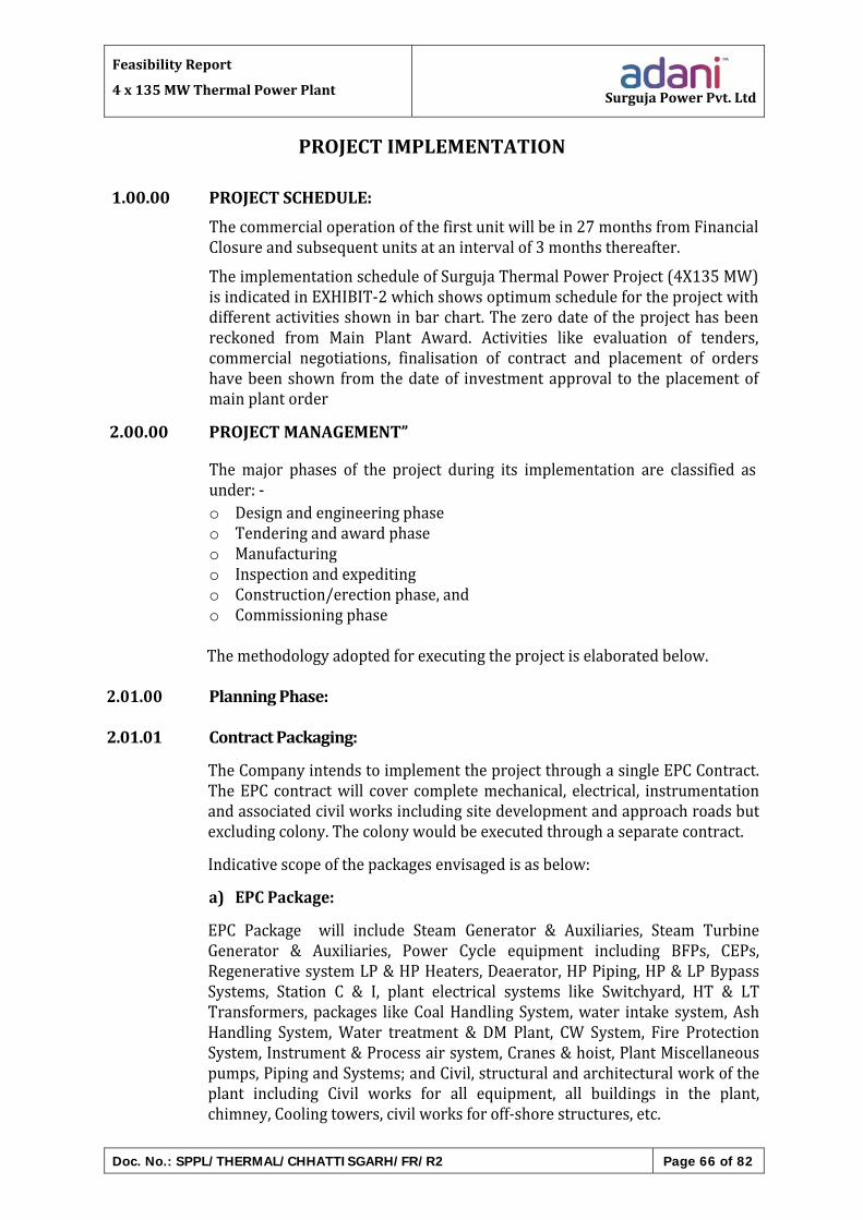
FeasibilityReport
4x135MWThermalPowerPlant SurgujaPowerPvt.Ltd
Doc. No.: SPPL/THERMAL/CHHATTISGARH/FR/R2 Page 66 of 82
PROJECTIMPLEMENTATION
1.00.00 PROJECTSCHEDULE:
Thecommercialoperationofthefirstunitwillbein27monthsfromFinancialClosureandsubsequentunitsatanintervalof3monthsthereafter.
TheimplementationscheduleofSurgujaThermalPowerProject(4X135MW)isindicatedinEXHIBIT‐2whichshowsoptimumschedulefortheprojectwithdifferentactivitiesshowninbarchart.Thezerodateoftheprojecthasbeenreckoned from Main Plant Award. Activities like evaluation of tenders,commercial negotiations, finalisation of contract and placement of ordershavebeenshown fromthedateof investmentapproval to theplacementofmainplantorder
2.00.00 PROJECTMANAGEMENT”
The major phases of the project during its implementation are classified asunder:‐o Designandengineeringphaseo Tenderingandawardphaseo Manufacturingo Inspectionandexpeditingo Construction/erectionphase,ando Commissioningphase
Themethodologyadoptedforexecutingtheprojectiselaboratedbelow.
2.01.00 PlanningPhase:2.01.01 ContractPackaging:
TheCompanyintendstoimplementtheprojectthroughasingleEPCContract.TheEPC contractwill cover completemechanical, electrical, instrumentationandassociatedcivilworksincludingsitedevelopmentandapproachroadsbutexcludingcolony.Thecolonywouldbeexecutedthroughaseparatecontract.
Indicativescopeofthepackagesenvisagedisasbelow:
a) EPCPackage:
EPC Package will include Steam Generator & Auxiliaries, Steam TurbineGenerator & Auxiliaries, Power Cycle equipment including BFPs, CEPs,RegenerativesystemLP&HPHeaters,Deaerator,HPPiping,HP&LPBypassSystems, Station C & I, plant electrical systems like Switchyard, HT & LTTransformers, packages likeCoalHandling System,water intake system,AshHandling System, Water treatment & DM Plant, CW System, Fire ProtectionSystem,Instrument&Processairsystem,Cranes&hoist,PlantMiscellaneouspumps,PipingandSystems;andCivil,structuralandarchitecturalworkoftheplant including Civil works for all equipment, all buildings in the plant,chimney,Coolingtowers,civilworksforoff‐shorestructures,etc.

FeasibilityReport
4x135MWThermalPowerPlant SurgujaPowerPvt.Ltd
Doc. No.: SPPL/THERMAL/CHHATTISGARH/FR/R2 Page 67 of 82
EPC Contractor will establish a comprehensive reporting structure, whichbroadlyincludes:
ManagementReports–ProgressReports,ExceptionReports,etc.
QualityAssuranceandControlProgramme–Shopandsite
SiteSafety,HealthandEnvironment
StatutoryPermitsandClearances
b) OtherWorks:
ThiswillbecarriedoutbySPPLthroughseparatecontractors/suppliers.Thiswillincludeprocurementofstandardtools,mobileequipment,firetenderandconstructionofresidentialcolony.
ThedevelopmentofEPCpackageisinitiatedatthestagewhentheFeasibilityReport is being considered for approval. The EPC package is developedbeforefinalisationoftheMasterNetworkprogrammeoftheprojecttoensurethat Master Network heads are developed in accordance with the EPCpackageforbettermonitoringandcontrol.
2.01.02 MasterProjectImplementationProgramme‐MasterNetwork(MNW): TheMasterNetworkidentifiesthekeymilestonedatesforeachpackageinthearea of engineering, procurement, manufacturing, dispatch, construction,erection, testing& commissioning.TheMasterNetwork,which is theoverallprogramme of the project implementation, will be finalized in consultationwith theEPCContractorand ImplementationConsultant.ThedateofNotice‐to‐ProceedoftheEPCcontractwillbethezerodateoftheMasterNetwork.
2.01.03 ImplementationConsultant:The Project Company will monitor the project in consultation withImplementationConsultant,whowillassistthemthroughoutthedevelopmentof theProject, frompreparationofRFPdocument for theEPCContractor tillhandingoverofthePlantbytheEPCContractor.TheImplementationConsultantwouldundertakethevarioustasksrelatedtotheengineering,design,projectimplementation/managementandmonitoring.Apart from this, they would also provide necessary engineering back upsupportduringconstruction,installationandcommissioningatsite.The drawings and documents generated by the EPC Contractor would bereviewedandchecked/approvedbytheImplementationConsultanttoensurethefollowing: Compliancetothecontractrequirements

FeasibilityReport
4x135MWThermalPowerPlant SurgujaPowerPvt.Ltd
Doc. No.: SPPL/THERMAL/CHHATTISGARH/FR/R2 Page 68 of 82
Compliancetothevariouslocal/statutoryauthorities Correctdesignandtechnology Various interfaces amongst various systems / equipment / sub‐
contractorsFurther,ImplementationConsultantwillalsobeinvolvedinshopinspectionofvariouscriticalequipment/componentsinlinewiththeagreedprojectqualityassuranceplan.ImplementationConsultantwillalsobeinvolvedinensuringfieldengineering/ construction quality as well as ensuring that the contractor meets allguaranteedparametersduringperformancetestingoftheUnit.
2.02.00 Tendering,AwardofContracts&EngineeringPhase:2.02.01 Engineering,Planning,MonitoringandControl:
TheBasicEngineeringStudiesareinitiatedassoonasFeasibilityReporthasbeen submitted and all major technical parameters of the project arefinalisedanddocumentedaspartofRevisedCostEstimates(RCE)alongwiththedetailedestimatesofcostandquantities.
TheEngineeringplanandscheduletheprojectengineeringactivitieswithinthe time frame specified for the engineering milestones in the finalisedMasterNetwork.TheEngineeringprogrammeatLevel‐2accordinglyshowsthedatesfordataavailability,tenderdrawingrelease,specificationrelease,bidevaluationandconstructiondrawingrelease,etc.The schedule drawn up by each Engineering discipline also takes intoconsideration theassistance fromExternalEngineeringConsultants thatcanbeadvantageously supplemented to the internal resources depending upon thecomplexity of an equipment system, the need for inducting latest availabletechnology, the large quantum of fairly simple engineering work, etc. Theengineering manpower resources are then allocated depending upon theprioritiesinthescheduleofeachengineeringdiscipline.
Departmental reviews are conducted by Project Engineering Coordinators toevaluate the work actually performed vis‐a‐vis detailed schedules. Correctiveactions within the scope of the discipline heads are identified and the plansupdated. The Engineering status appraisal from the heads of differentEngineering Disciplines is then reviewed to check the various areas ofspecification release, bid evaluation, drawing releases, etc. against the targetlevel‐2programmedates.Ifanydelayisexpectedtoaffectthescheduleofothercontrol centres, the corrective action to rectify the situation by either re‐allocatingprioritiesofinternalresourcesorbyseekingtheassistanceofExternalEngineeringAgenciesisresortedto.
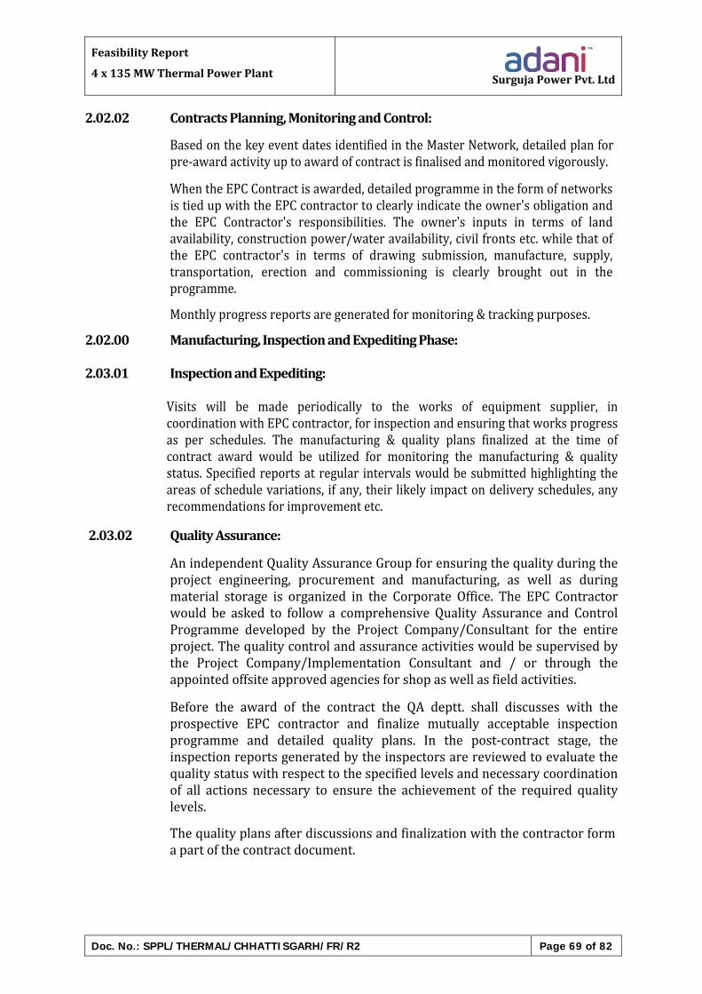
FeasibilityReport
4x135MWThermalPowerPlant SurgujaPowerPvt.Ltd
Doc. No.: SPPL/THERMAL/CHHATTISGARH/FR/R2 Page 69 of 82
2.02.02 ContractsPlanning,MonitoringandControl:
BasedonthekeyeventdatesidentifiedintheMasterNetwork,detailedplanforpre‐awardactivityuptoawardofcontractisfinalisedandmonitoredvigorously.
WhentheEPCContractisawarded,detailedprogrammeintheformofnetworksistiedupwiththeEPCcontractortoclearlyindicatetheowner'sobligationandthe EPC Contractor's responsibilities. The owner's inputs in terms of landavailability,constructionpower/wateravailability,civilfrontsetc.whilethatofthe EPC contractor's in terms of drawing submission, manufacture, supply,transportation, erection and commissioning is clearly brought out in theprogramme.
Monthlyprogressreportsaregeneratedformonitoring&trackingpurposes.
2.02.00 Manufacturing,InspectionandExpeditingPhase:
2.03.01 InspectionandExpediting:
Visits will be made periodically to the works of equipment supplier, incoordinationwithEPCcontractor,forinspectionandensuringthatworksprogressas per schedules. The manufacturing & quality plans finalized at the time ofcontract award would be utilized for monitoring the manufacturing & qualitystatus.Specifiedreportsat regular intervalswouldbesubmittedhighlighting theareasofschedulevariations, ifany, their likely impactondeliveryschedules,anyrecommendationsforimprovementetc.
2.03.02 QualityAssurance:
AnindependentQualityAssuranceGroupforensuringthequalityduringtheproject engineering, procurement and manufacturing, as well as duringmaterial storage is organized in the Corporate Office. The EPC Contractorwould be asked to follow a comprehensive Quality Assurance and ControlProgramme developed by the Project Company/Consultant for the entireproject.Thequalitycontrolandassuranceactivitieswouldbesupervisedbythe Project Company/Implementation Consultant and / or through theappointedoffsiteapprovedagenciesforshopaswellasfieldactivities.
Before the award of the contract the QA deptt. shall discusses with theprospective EPC contractor and finalize mutually acceptable inspectionprogramme and detailed quality plans. In the post‐contract stage, theinspectionreportsgeneratedbytheinspectorsarereviewedtoevaluatethequalitystatuswithrespecttothespecifiedlevelsandnecessarycoordinationof all actions necessary to ensure the achievement of the required qualitylevels.
Thequalityplansafterdiscussionsandfinalizationwiththecontractorformapartofthecontractdocument.

FeasibilityReport
4x135MWThermalPowerPlant SurgujaPowerPvt.Ltd
Doc. No.: SPPL/THERMAL/CHHATTISGARH/FR/R2 Page 70 of 82
2.04.00 ConstructionPhaseandCommissioningPhase:
2.04.01 ConstructionPlanning,MonitoringandControl:
Site activities start progressivelywith the award of EPCContract based ontheMasterNetworkschedule (Level‐1network),during theaward,Level‐2networks are finalised, keeping in view the interface events needed to berealised. Execution group at site starts interactionwith the EPC contractorsoonafterthereceiptoftheLetterofAwardtoestablishthesiteoffice.BasedontheL‐2network,siteFieldEngineeringGroupalsostartsinteractionwithCentralEngineeringGroup toget the requireddrawings in the sequence inwhichtheyareneededforcontinuousworkforthenextsixmonths.
2.04.02 ProjectReviewTeamMeeting:
A Project Review Team headed by the Project Head with members fromvarious departments at the head office and site is constituted for everyprojecttoreviewtheprogressofprojectonamonthlybasis.Themeetingofthe team isconductedeverymonth.This ischairedby theProjectHeadandattended by different departments of Head Office and Site. The meetingreviewsbothpre‐awardandpost‐awardprogressofEPCcontract.
Interface problems among Engineering, Contracts and Site affecting projectexecutionarealsoreviewedandappropriatedecisionstakentoexpeditethereleaseofdrawings,materialsandsuchotherrequirements.
Budgetary review is also done during this meeting and shortfall, if any,identifiedandresponsibilitycenterfixedtogetthecommitment.

FeasibilityReport
4x135MWThermalPowerPlant SurgujaPowerPvt.Ltd
Doc. No.: SPPL/THERMAL/CHHATTISGARH/FR/R2 Page 71 of 82
OPERATION&MAINTENANCEPHILOSOPHY
1.00.00 GENERAL:
Thepurposeof thissection is tobroadlyoutline theoperationandmaintenancephilosophytobeadoptedforthisproject.Thiswillactasausefulinputforbasicaswell as Detailed Engineering of the Project so that all required provisions foroptimum Operation and Maintenance of this plant are made during theEngineeringstageitself.
2.00.00 OPERATIONPHILOSOPHY:2.01.00 OverallRequirement:2.01.01 BaseLoadStation:
TPPatSurgujawillbeapitheadcoalbasedstationandwillbebasicallydesignedtoworkasbaseloadstation.
2.01.02 Design:
The design of Surguja (4X135MW) TPPwill cover adequate provision for thefollowing:
a)Capabilityofrapidunloadingfromfullloadtonoloadundercontrolledconditionsinnotmorethan20minutestominimizeturbinecooling.
b)Capabilitytoachievefullloadwithin30minutesaftersynchronisingsubsequenttoan8hourshutdown(overnight).
2.01.03 HouseLoadOperation:
Themainplant,auxiliariesaswellasallassociatedsystemsandcontrolswillbedesignedtopermithouseloadoperation,withoutshuttingdowntheunitintheevent of sudden loss of load demand due to tripping of transmission lines orother grid disturbances. It should also be designed for part load operation onconsistentbasis.
2.01.04 ParticipationinLoadFrequencyControl:
The design ofmain plant control systemswill permit participation of variablepressure operation and two shift operation in load frequency control in theeventofsystemdisturbances.
2.02.00 DESIGNFORHIGHUNITAVAILABILITY:2.02.01 General:
Highavailabilityoftheunitandallassociatedauxiliariesandsub‐systemsisoneofthemainO&MobjectivesforensuringhighPLFandlowpartialloading.This

FeasibilityReport
4x135MWThermalPowerPlant SurgujaPowerPvt.Ltd
Doc. No.: SPPL/THERMAL/CHHATTISGARH/FR/R2 Page 72 of 82
objectivewillbeimplementedbyadoptingthefollowingprinciples:‐
a) Use of equipment and systemswhose design performance and high
availability has been fully established by a considerable record ofsuccessfuloperationforsimilarserviceconditionsincoalfiredutilitypowerstations.
b) Useofonlyfieldprovendesignconceptsandconservativedesigns.
c) Special consideration forproper approach for easeof operation andmaintenancewhile selecting the equipment andwhile finalizing thelocationandlayoutplans.
d) Strict implementation of quality assurance norms during design,manufactureaswellasinstallationandcommissioningstage.
e) Strict compliance with approved commissioning documentation,comprising of Standard Checklists, Testing Schedules andCommissioning Schedules etc., forming a part of commissioningdocumentsfortheproject.
f) Easyaccessibilityandmaintainabilityof theequipmentshallbetheprimeconsiderationduringselectionofthesame.
g) Approachabilityofequipmentforeasyoperationshallbeconsideredduringdetailedengineeringstage.
2.02.00 SizingofCriticalEquipment‐Margins&Standby:
Provision of adequate margins will be made while sizing all‐importantauxiliariesandsub‐systemstoensureoperationoftheunitundertheworstconditionsandafternormalwear.Thefollowingaspectswillbekeptinview:
a) Theunitasawholeshallbesuitabletogenerateat105%ofthenameplate rating on a sustainable basis to meet the requirement of thegrid.
b) Eachmajorequipment(fans,BFP's,CEP's,CCpumps,ECWpumps,CW pumps etc) will be capable of meeting 60% of Boiler MCRrequirements. However, while sizing adequate range‐ability andturndown capability will also be provided for proper operation ofrelatedcontrolsystems.
c) Theunitandequipmentcontrol systemshallbedesigned insuchaway that the unit will survive the loss of major equipment andcontinuetooperateatalowerload.
d) The number and size of Feederswill be so selected thatwithworstcoalatBMCRoneFeederwillbespare.WithworstcoalatTMCRand

FeasibilityReport
4x135MWThermalPowerPlant SurgujaPowerPvt.Ltd
Doc. No.: SPPL/THERMAL/CHHATTISGARH/FR/R2 Page 73 of 82
alsowithdesigncoalatBMCRtwoFeederswillbespare.2.02.03 CoalHandlingPlant:
The design and sizing of coal handling plant has an important bearing onstation plant load factor. Hence, the following steps will be taken whiledesigningthecoalhandlingplantsoastoensurehighPLFforthestations:
a) CHPshallbeabletomeetthedailycoalrequirementconsidering101%PLFanddesigncoal.
b) Adequatestandbycapacitywillbeprovided in thecoalhandlingplantandforcrusherssothatoutageofasinglecrusherorotherequipmentwillhavenoeffectatfullloadoperationofstationwithworstcoal.
c) CHP evacuation rate shall match with coal transportation systemunloadingratesuchthatthereisnodetentionofloadedcoalrakeatthetrackhopper/wagontripplerterminal.
d) Adequate number of properly designed suspended magnets andonline magnetic separators, Metal Detectors will be provided tosegregatemagneticandnon‐magneticmaterialsrespectively.
e) TominimisethedustnuisanceinCHParea,effectivedustsuppressionsystem shall be provided in wagon tippler, bunker floor, transferpointsandstockyard.Dustextractionsystemshallbeprovided in thecrusherhouse.
f) Effective provision shall be made for accurate and reliablemeasurementofincomingcoalandcoalconsumedbyeachunit.
g) In order to take care of unforeseen disruption in coal supplies, coalstockyardequal to15days full load requirementwillbedesignedatstationend.
h) In order to avoid flooding of underground portions, all conveyorgalleries shall be over‐ground except wagon tippler and connectedconveyors.
i) Coalbunkers shallbedesigned toavoidchoking/ratholingetc. aftercarryingoutcoalflowabilitystudies.
J) Provision of blending of different types of coal shall be kept whiledesigningCHPsoastofeedcoaltobunkerswithinreasonablequalityrange.
2.03.00 DesignforEfficientOperation:
ThebasicandDetailedEngineeringoftheprojectwillbedonesoastohelpin

FeasibilityReport
4x135MWThermalPowerPlant SurgujaPowerPvt.Ltd
Doc. No.: SPPL/THERMAL/CHHATTISGARH/FR/R2 Page 74 of 82
achievinghighstandardofOperationalPerformanceespeciallywithrespecttoefficiency&HeatRate.Thismayincludethefollowingkeyindices.
a) Lowauxiliarypowerconsumption
b) Lowmake‐upwaterconsumption
c) Nooilsupportabove40%MCRoperation.d) Optimumefficiencyandheat rates for theunitsand their subsystemby
achievingdesignparameters.
Provisionwillbemadeforaccurateandreliablemeasurementofcoalreceipt,coalconsumptionperunitoilreceiptandoilconsumptionperunit,totalD.M.Water production and make‐up water consumption per unit, generatoroutput, auxiliary power consumption, flue gas oxygen content etc. Thesevalues will be fed to Information System (IS) and daily reports regardingreceipt,consumptionandstockpositionwillbeprepared.
Adequate provision of sequence controls, safety interlocks and protection,automatic modulating controls and operator guidance messages throughCRTwill bemade to assist the operators in safe and efficient operation oftheseunits.
Provisionwillbemadeforon‐lineperformancecalculationsfortheunitandmajorsub‐systemsinDAS.OnlineCRTdisplayofheatratepenaltiesduetodeviationofkeyparametersfromthedesignvalueswillbeprovidedbyHMI.
Provisionshallbemadetomonitorpowerbeingexportedfromthestation.
TO ACHIEVE OPTIMUM EFFICIENCY, FOLLOWING PROVISIONSSHALLBEMADE:
a) Spraywater for reheatersteamshallbe tapped from feedwater lineafter thehighpressureheaters to takeadvantageof thegaindue tofeedwaterheating.However,tocompensateforthepassingofspraycontrol valves due to excess spray water pressure, multistage orequivalentvalveshallbeusedbeforespraycontrolvalves.
b) Condensershallhaveanonlinetubecleaningsystem.Provisionshallalso bemade to supply condenserwith clean& suitably chemicallytreated water to avoid fouling in condenser tubes and for properfunctioningofthetubecleaningsystem.
c) HighpressurefeedwaterheatersshallbedesignedfornegativeTTDtogainmaximumheatfromextractionsteam.
d) Optimumheat transfer in boiler 'shall bemonitored and effected byinstalling a boiler cleanliness monitoring system. Intelligent soot

FeasibilityReport
4x135MWThermalPowerPlant SurgujaPowerPvt.Ltd
Doc. No.: SPPL/THERMAL/CHHATTISGARH/FR/R2 Page 75 of 82
blowingusingtheaboveshouldbeapartofthesystem.
e) HP and IP turbine first few stage fixed & rotating blades shall bedesignedsoastohaveminimumerosionbetweenOverhauls.
f) Turbine shall be provided with high and sustained efficiency seals,withprovenrecordofsatisfactoryperformance.
g) Large equipments like ID fans shall be provided with variablefrequency drive to reduce power consumption during part loadoperation.
h) TubularAirPreheatersshallbeprovidedtocompletelyavoidtheairleakage.
i) Care shall be takennot touse film type fills inCTs to avoidblockageandefficiencyloss.
j) ESPsandassociatedFluegastreatmentequipmentsshallbedesignedto achieve parameters better than latest environmental norms forchimneygaswithoutfluegasconditioning.
2.04.00 InstrumentationforEfficiencyMonitoring:
a) Flue gas exit temp, measurement shall be done using multiplethermocouple sensing from different points of a grid in the crosssectionofduct
b) Pr. Helium Detector/Temp, measurement instruments at HP & IPturbine inlet and outlet, all extraction lines, drip lines and heaterinlet/outletfeedwaterlinearerequiredtobeofveryhighaccuracytoprovide accurate temp. Press measurement for correct cylinderefficiency&heaterperformancecalculations condenserperformancewithonlineinstruments.
c) FluegassamplingprovisionatAirPreheaterinletandoutletshallbeofmultipleprobetypeforcollectingsamplesfromdifferentpointsinagridacrossthecrosssection.
d) HightemperatureO2probesshallbeprovidedatthefurnaceexitsoas
tomonitorcombustionefficiency.
InstrumentationforReliability:
Main turbine/ Generator, shall be having on line performance &vibrationbaseddiagnosticsystem.
Accuracy of the on‐line instruments used for absolute pressure/differentialpressure,temperaturefordeterminingcylinderefficiency,heater performance and condenser performance shall be of 0.2%classorequivalent.

FeasibilityReport
4x135MWThermalPowerPlant SurgujaPowerPvt.Ltd
Doc. No.: SPPL/THERMAL/CHHATTISGARH/FR/R2 Page 76 of 82
2.05.00 DesignforABTRequirement:
UnderABTregime,followingfurtheroperatingconditionsarerequiredtobetakencareof:
a) Thereare96timeblocksinadayof15mins.eachandtheremaybearequirementofchangingUnitloadwithchangeinfrequencyineachblock.
b) Unitmayhavetobekeptunderreserveshutdownandbroughtbackfastaspergriddemand,
c) Very high availability target (> 80%) to bemet for full fixed chargerecovery.
d) MinimumPartialLoading.e) To meet such extended requirements, following design
considerationsaretobemet;
i) Unitshouldbedesignedforafasterrampup/Rampdownratewithouteffectingunduethermalstresses.
ii) Unitshallbecapableofmeetingtherequirementof faststartupandquickloadingtillfullload.
iii) Steamgenerator,Turbinegeneratorandtheirauxiliariesshallbe designed to run with satisfactory performance from oneoverhaultoanotherwithoutrequiringanymajorshutdown.
2.06.00 OperationManagementSystem(OMS):
The operation of this projectwill be optimized by implementing OperationManagementSystem.Thissystemcoverscleardefinitionofresponsibilitiesofall key executives including shift‐in‐charge, AGM/DGM (Operation), AGM(O&M)/GM etc. and lays down the procedure for detailed analysis of O&Mproblems.ItalsocoversthesystemofdailyreportingtoCorporateOfficeandmonthlyoperationreviewteam(ORT)meetings.
2.07.00 OperationReviewTeam(ORT)Meetings:
The following important aspect will be covered during the monthly ORTmeetings:
a) Review of actual performance of the station and each unit vis‐a‐vistargets and norms for key operating parameters like generation,availabilityanddeviationsonheatrate,specificcoal/oilconsumption,make‐upwaterconsumption,auxiliarypowerconsumptionetc.
b) Review of specific O&M problems of the project and progress ofcorrectiveactions.
c) Review of external constraints like coal supply problems, power

FeasibilityReport
4x135MWThermalPowerPlant SurgujaPowerPvt.Ltd
Doc. No.: SPPL/THERMAL/CHHATTISGARH/FR/R2 Page 77 of 82
evacuationproblemsandotherrelateddifficulties.
d) Reviewofcommercialandfinancialperformance.
e) Reviewofhousekeepingstandard. Proper implementation of OPMS and regular ORT meetings are
expectedtohelpinachievementofhighstandardofplantoperation.
2.08.00 TrainingofO&MPersonnel:
Since O&M cadre for this project is likely to be largely based on freshengineeringgraduates,considerableimportancehastobegiventotrainingofO&Mpersonnel so that therequiredskills invariousspecialiseddisciplinescouldbecreatedintheshortestpossibletime.Itisthereforeveryimportantto ensure that all engineers meant for maintenance become fully familiarwith their area of work ( O&M Dept.). This will be achieved at least 24monthspriortosynchronisationofunitby:
a) StudyofO&MManualsandDrawings.
b) Review/Preparationandfinalizationofcommissioningdocuments.
c) Supervisionofpre‐commissioningandcommissioningactivity.
d) Preparationofdocumentsformaintenancemanagementsystem.
e) Participationinactualmaintenanceworkinsimilarproject.
f) Participationinannualoverhaulingworkinoneproject.
g) Training at manufacturer's works in specialized areas/ simulator/otherutilities.
This on‐the‐job training activity will be co‐ordinated by AGM (O&M) andProject Co‐ordinator fromCorporate Training in the areas of operation andmaintenanceofmodernfacilitiesshallalsobeorganised
2.08.01 TrainingofOperationEngineers:
I)SimulatorTraining:
The operation engineers will undergo extensive training on replicasimulator at Simulator Training Institute, Korba/Sipat. This trainingwillbesodesignedastofullyequiptheoperatorswiththerequisiteknowhowand confidence to effectively handle all plant upsets and crisis situationwhicharelikelytoariseinaplant.
ii)TrainingatmanufacturersWorksandotherUtilities:Theoperationengineerswillundergoextensivetrainingatmanufacturerswork for familiarisationand fordesign/testingaspects.Theywill alsobe
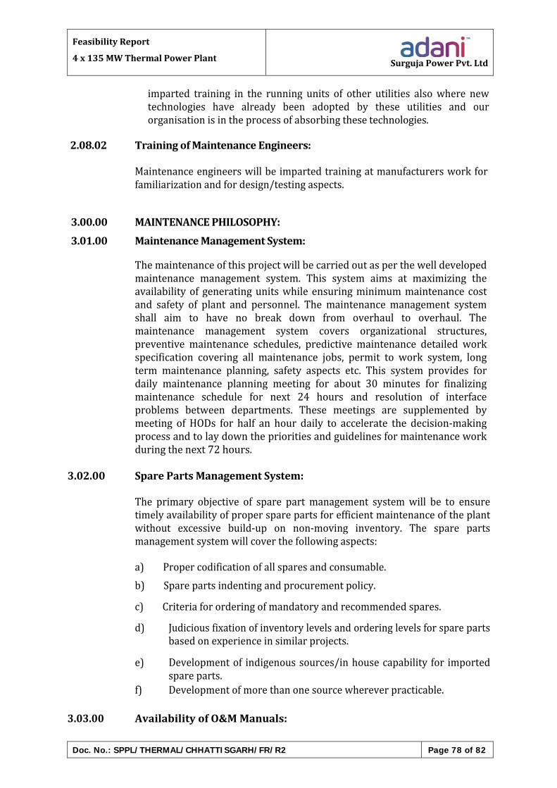
FeasibilityReport
4x135MWThermalPowerPlant SurgujaPowerPvt.Ltd
Doc. No.: SPPL/THERMAL/CHHATTISGARH/FR/R2 Page 78 of 82
imparted training in the running units of other utilities also where newtechnologies have already been adopted by these utilities and ourorganisationisintheprocessofabsorbingthesetechnologies.
2.08.02 TrainingofMaintenanceEngineers:
Maintenanceengineerswillbe impartedtrainingatmanufacturersworkforfamiliarizationandfordesign/testingaspects.
3.00.00 MAINTENANCEPHILOSOPHY:
3.01.00 MaintenanceManagementSystem:
Themaintenanceofthisprojectwillbecarriedoutasperthewelldevelopedmaintenance management system. This system aims at maximizing theavailabilityof generatingunitswhile ensuringminimummaintenance costand safety of plant and personnel. The maintenancemanagement systemshall aim to have no break down from overhaul to overhaul. Themaintenance management system covers organizational structures,preventive maintenance schedules, predictive maintenance detailed workspecification covering all maintenance jobs, permit to work system, longterm maintenance planning, safety aspects etc. This system provides fordaily maintenance planning meeting for about 30 minutes for finalizingmaintenance schedule for next 24 hours and resolution of interfaceproblems between departments. These meetings are supplemented bymeeting of HODs for half an hour daily to accelerate the decision‐makingprocessandtolaydowntheprioritiesandguidelinesformaintenanceworkduringthenext72hours.
3.02.00 SparePartsManagementSystem:
The primary objective of spare part management systemwill be to ensuretimelyavailabilityofpropersparepartsforefficientmaintenanceoftheplantwithout excessive build‐up on non‐moving inventory. The spare partsmanagementsystemwillcoverthefollowingaspects:
a)Propercodificationofallsparesandconsumable.
b)Sparepartsindentingandprocurementpolicy.
c)Criteriafororderingofmandatoryandrecommendedspares.
d) Judiciousfixationofinventorylevelsandorderinglevelsforsparepartsbasedonexperienceinsimilarprojects.
e) Developmentof indigenoussources/inhousecapability for importedspareparts.
f) Developmentofmorethanonesourcewhereverpracticable.
3.03.00 AvailabilityofO&MManuals:

FeasibilityReport
4x135MWThermalPowerPlant SurgujaPowerPvt.Ltd
Doc. No.: SPPL/THERMAL/CHHATTISGARH/FR/R2 Page 79 of 82
a)Allcontractswillincludeprovisionof8setsof"DRAFT"O&MManualstobesuppliedbyvendorwithin12monthsfromthedateofLOA.
b)ThedraftO&MManualswillbereviewedbyprojectengineeringgroup/corporate engineering and corporate knowledge team to ensurecompleteness and proper coverage. The finalmanualswill incorporateallthecomments.
c)Schematicdiagrams,P&Idiagrams,wiringdiagrams,cableschedule,valveschedules,pipescheduleetcshallalsobesubmittedbyvendor.
d) "FINAL" O&MManuals (15 sets prints and 3 CD ROMs),whichwill bedistributed to all concerned as per the approved distribution policy ofthecompany,willbeavailabletoallconcernedatleast18monthspriorto synchronisation of unit to avoid problems in preparation ofcommissioningdocumentaswellasproperinstallation&commissioningofequipment.
3.04.00 SpecialToolsandTackles:
All contractswill include theprovision for supplyof twounusedsetsof allspecialtoolsandtackleswhicharerequiredfor installation,Commissioningand propermaintenance of plant and equipment. These two sets of specialtools and tackles will be handed over to O&M department within one (1)monthofcommissioningofthefirstunit
Suitable lifting tools and tackles shall be provided for carrying outmaintenancewithfullsafety.Quickerectscaffoldingforboilerfurnaceandsetofskyclimbershallalsobepartofspecialtoolsandtackles.
Pneumatictools,rollersupportinturbinerotorsshallalsobearranged.4.00.00 COALSUPPLYMANAGEMENT:
The minimum requirement of coal will be based on operating norms.However, the monthly requirements will be finalised through Coal SupplyAgreements. In order to meet the actual requirements of the project, themineswillkeepaprovisionfor10%increaseordecreaseinsuppliesfromtheagreedaveragelevel.
The coal loading andhandlingplant atMine and coal handlingplantwill bedesignedtomeetthepeakrequirementondailybasiswithadequatereservecapacitytotakecareofnormalbreakdownsandmaintenancerequirements.
5.00.00 ENERGYCONSERVATIONASPECTS:5.01.00 Introduction:
All consumers of electricity, irrespective of their power demand, are

FeasibilityReport
4x135MWThermalPowerPlant SurgujaPowerPvt.Ltd
Doc. No.: SPPL/THERMAL/CHHATTISGARH/FR/R2 Page 80 of 82
requiredtobecomeconsciousaboutenergyconservationandshouldthinkofwaysandmeanstooptimisetheirenergyconsumption.Butitisallthemorevery important for a power plant,which happens to be one of the biggestconsumerofelectricity,tothinkofreducingitsownpowerconsumption.
5.02.00 SelectionofSteamParametersandFeedHeatingCycle:
Thermal efficiency of the Cycle can be improved by raising main steamparameters(pressureandtemperature),introducingreheatingofsteamatasuitablestageofexpansion,improvingcondenserVacuumandoptimimizingregenerative feed water heating arrangement. Improvement in thermalefficiencymeanssaving infuelburnt inboilerandalsosignificantsaving inpower consumptionofplantauxiliaryequipment in turnaneffort towardsenergyconservation.
ThethermalcycleparametersshallbeoptimisedforthisrangeofunitratingbyselectingparametersofMainsteamtemperature,pressure,reheatsteamtemperatureandcondenserpressuretoprovideanoptimumthermalcycle.The cycle employs regenerative feed water heaters thereby ensuringoptimumturbineheatrate.Thelossesthroughfluegashavebeenkepttoaminimum.
5.03.00 CoalHandlingPlant:CoalHandlingPlantforfeedingcoaltotheBoilerBunkershasbeenenvisagedwiththefollowingmajorfeaturestominimizetheconsumptionofenergy:
a) Coal handling plant layout shall be finalized with very less number of
conveyersinordertominimizethetotalcoal‐conveyingpath.b) Crusherhouseheightshallbereducedpreventingun‐necessaryconveying
ofcoaltohigher‐elevations.c) Fordustcontrolatcoal transferpointsdustsuppressionsystemshallbe
provided exclusively for reducing the energy consumption levels toalmost nominal values compared to dust extraction system, which arerestrictedtocrushhouseonly.
5.04.00 MonitoringofKeyParameters:
The following critical parameters/systems shall bemonitored regularly tokeeptheminlinewithdesignvaluesandtoachieveoptimumefficiency:i) Boilerwaterandsteampressures.ii) Boilerwaterandsteamtemperatures.iii) Boilerwaterandsteamflows.iv) Percentageoffluegasoxygenprovidedbyagridofprobesand excessair.v) Combustionairandfluegassidedraftloss,vi) Exitgastemperaturesatdifferentsections,

FeasibilityReport
4x135MWThermalPowerPlant SurgujaPowerPvt.Ltd
Doc. No.: SPPL/THERMAL/CHHATTISGARH/FR/R2 Page 81 of 82
vii) Fuelandcombustionairflows,viii) Superheatandreheatsprayflows.ix) Boilerflameintensityfromscannersaswellasflamemonitors,x) Condenservacuumxi) Sootbloweroperation,xii) Un‐burntcarboninash.
xiii) Oxygen&Carbonmonooxideinfluegas,providedbyareliableon‐linemeasurement.
xiv) Coalquality(asfired)xv) CWinletandCWoutlettemperatures.
The above list is not exhaustive. Any deviation in the parameters shall becorrectedat theearliest.However,efficiencytestasenvisagedshallbecarriedoutregularlytoascertaintheefficiencygaps.
5.05.00 Chemistry:
Continuousmonitoring and control ofwater and steampurity in the plant cyclewill further improve the heat transfer rate in heat exchanger tubes, it lean beachievedbythefollowingchemistrycontrolphilosophy:
ChemistryControl=:
1. The 100% Condensate to be treated in CPU. Therefore a standby 50%treatmentfacilityshallbeavailableallthetime.
2. Themakeupwatershouldhavethefollowingcharacteristics:a. Conductivitylessthan0.1(js/cm,b. Silicalessthan5ppb,
3. The parameters to be monitored by on‐line instruments and coreparametersareindicatedinControlroomwithalarmandthelimitvalue.Thetotalchemistrycontrolandmonitoring isdonebyChemistryexpertsoftwaretoalertandinformoperatorfordesiredactions.
4. Followingparametersaretobemonitoredcontinuouslyon‐lineinwater/steamcycle:
a. CationconductivityatCEPdischarge;CPUoutlet;FeedwaterandMainsteam
b. Conductivity‐—do—c. pH atFeedwaterd. Silica atFeedwaterandmainsteame. DissolvedOxygen atCondensateandFeedwaterf. Sodium atMainsteam;CEPdischargeandCPUg. ORP atCEPdischargeandFeedwater
5. The adequate arrangements including nitrogen capping (for dry orwetpreservation)shallbeprovidedforproperlayupoftheallthewaterandsteamtouchedsystemwhenunitisundershutdown.
6. Thechemicalfeeding(likeammoniaandHydrazine)shallbeperformedbyautomaticmode.

FeasibilityReport
4x135MWThermalPowerPlant SurgujaPowerPvt.Ltd
Doc. No.: SPPL/THERMAL/CHHATTISGARH/FR/R2 Page 82 of 82
5.06.00 OperationalOptimisation:
Automaticcontrollersareprovidedforplantoptimization.Theunitcapacitycontroller shall set load demand keeping the safety of the equipmentinherent.
Themaincontrollersusedforoptimumperformanceofthewholeplantareasfollows:
a) UnitCapacityController
i)BoilerCapacityController
ii)TurbineCapacityController
b) CombustionControl
i)Coalflow
ii)Airflow
c) SH/RHSteamtemperaturecontroller
d) Chemicaldosingcontroller
i)Hydrazine
ii)Ammonia
iii)Phosphate
e) Mainsteampressurecontroller
f) FWflowController(Drumlevel)
i)Lowrange
ii)Highrange
g) Deaeratorlevel
h) Hotwelllevel
i)HP/LPbypass
ii)PAheader
In addition to above, HMI is programmed to carryout on‐line performancecalculation like unit/turbine gross/net heat rate and efficiencies ofboilers/Turbines/allmajorauxiliariesandthusgivingimmediatefeedbacktothe management for analysis by unit performance improvement &optimisation.ISsystemalsohasprovisionfordifferentlogs.

4x135MWThermalPowerPlantFeasibility
Report
SurgujaPowerPvt.Ltd.
EXHIBIT‐1
SITELOCATION

4x135MWThermalPowerPlantFeasibility
Report
SurgujaPowerPvt.Ltd.
EXHIBIT‐1
TOPOSHEET
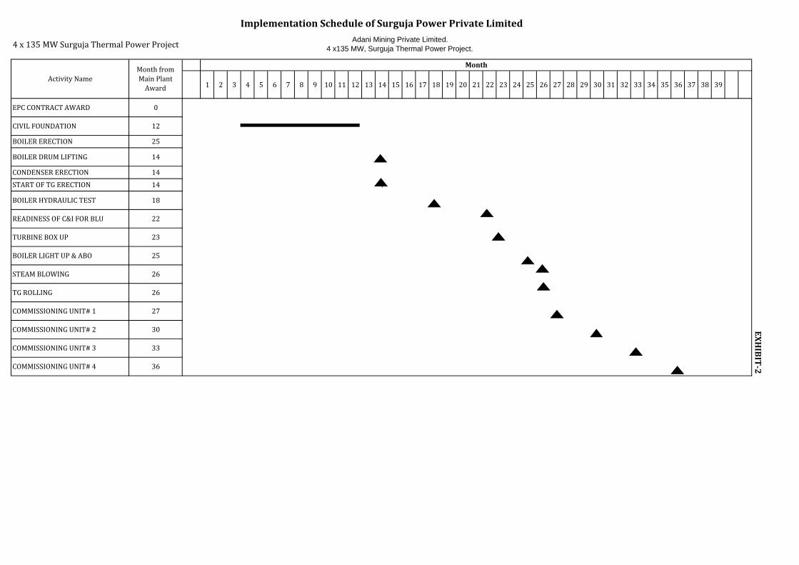
Adani Mining Private Limited.4 x135 MW, Surguja Thermal Power Project.4x135MWSurgujaThermalPowerProject
1 2 3 4 5 6 7 8 9 10 11 12 13 14 15 16 17 18 19 20 21 22 23 24 25 26 27 28 29 30 31 32 33 34 35 36 37 38 39
Month
BOILERLIGHTUP&ABO
STEAMBLOWING
TGROLLING
COMMISSIONINGUNIT#1
ImplementationScheduleofSurgujaPowerPrivateLimited
EPCCONTRACTAWARD
BOILERERECTION
BOILERDRUMLIFTING
25
14
MonthfromMainPlantAward
ActivityName
STARTOFTGERECTION
BOILERHYDRAULICTEST
0
12
CONDENSERERECTION
READINESSOFC&IFORBLU
25
26
33COMMISSIONINGUNIT#3
27
30COMMISSIONINGUNIT#2
26
36
TURBINEBOXUP
EXHIBIT‐2COMMISSIONINGUNIT#4
CIVILFOUNDATION
14
14
18
22
23
`

SurgujaPowerPrivateLimited.4x135MW,SurgujaThermalPowerProject.
PROJECTORGANISATIONSET‐UPEXHIBIT‐3
OPERATION & MAINTENANCE
MATERIALS FINANCE & HUMAN RES. PLANNING & EQUIPMENT CONSTRUCTION
CW SYSTEM OFF SITESMAIN POWER
GENERAL MANAGER
TOWNSHIP WORKS
TECHNICAL
MECH. ELECT. C & I CONTRACTORSWORKS

1193WATER REQUIRED / 4 X 135 MW 1637 M3/HR
39284 M3/DAY 1178510 M3/MONTH
WATER REQUIRED / 4 X 135 MW 14.14 MILLION M3 / YEAR 78473
16371511 1608 1648 279
1101 40 To SDB
72000 72000
8400 8400
1637 250
160
1696
40 AWU + AC MAKE UP WATER 1611
40 FLOOR WASHING + MISS..
20 PLANT POTABE WATER 85
59 133 127 123 106 90 90 84 55 To Plant cycle makeup
29 To CCCW make up & Chemical feed system
257 4 17 16 6 For Regenaration
133
51 From SSF & PSF Back wash
90 145 145
7676 To CMB 55
28 From IBD / CBD
76 90 83
NOTE : 1. COC Considered is 5.0 22 From DM Plant Effluent2. All flows as shown of are weighted average figure. 3. Both BA + FA conveying is considered to be dry mode (Pnematic conveying system) 20 From floor washing (Intermittent) 4. BMCR Flow considered is 460 TPH5. Plant cycle make up is 3% on BMCR 6. All units are in M3/Hr OWNER : SURGUJA POWER PRIVATE LIMITED7. Evaporation loss considered is 1.5% (maximum) 291 To Horticulture / Gardening PROJECT : SURGUJA THERMAL POWER PROJECT.8 Drift loss considered is 0 02% CONFIGURATION : 4 X 135 MW
WATER BALANCE DIAGRAM
RAW WATER
CASCADE AERATOR
CLARIFIER
CWST
PSF RO MB
COC = 5
IDCT
Condenser
BTG AUXI..
AHP AIR COMPRESSOR
DMWST
PLANT AIR
CENTRAL MONITORING BASIN (CMB)
BBD PIT
THICKNER
SLUDGE DRYING BED
COLLECTION TANK
UF CLARIFIER 2
8. Drift loss considered is 0.02% CONFIGURATION : 4 X 135 MW .9. Total dissolved solids considered as max.400 ppm SOURCE OF RAW WATER : REHAR AND ATEM RIVER .10. Total suspended solids considered as max. 500 ppm To CHP dust suppression & Ash wetting LOCATION : PARSA (VILLAGE) , SARGUJA (DIST),
CHHATTISGARH.


1 Coal stock pile - Reject based (1,00,000 MT - 7 days)
2 Raw coal (60,000 t-15 days)+Conveying+CHP
3 Power Block 7.02
Switch yard 4.07
Reservoir 5.28
6 Water treatment 2.40
7 Admn+ Stores+Fire Station+WS 1.04
8Cooling Towers, Cold water channels area including
CW Pump House and its associated piping5.51
9 AHP 1.60
10 Fuel oil 0.30
11 Road, drains, miscellaneous 12.93
12 Green Belt As per mine plan
Total area 47.50
Land requirement for Surguja Power Plant
DescriptionSl.
No.
4
5
7.35
Area in Ha