

LENNOXOEMPARTS.COM
Page 1 1998 Lennox Industries Inc.Litho U.S.A.
Corp. 9814-L8G23(X)
Service Literature Revised 08-2001
G23(X) SERIES UNITSG23(X) series units are mid-efficiency upflow gas fur-naces manufactured with Duralokt aluminized steelclamshell type heat exchangers. G23(X) units are avail-able in heating capacities of 50,000 to 150,000 Btuh andcooling applications up to 6 tons. Refer to EngineeringHandbook for proper sizing.Units are factory equipped for use with natural gas. A kit isavailable for conversion to LPG operation. G23(X)-1, -2, -3and -4 model units use electronic (intermittent pilot) ignition.G23(X)-5 and -6 model units feature the Lennox Sur-eLightT silicon nitride ignition system. All units meet theCalifornia Nitrogen Oxides (NOx) Standards and CaliforniaSeasonal Efficiency requirements with the installation offlame baffles. All units use a redundant gas valve to assuresafety shut-off as required by A.G.A. or C.G.A.Information contained in this manual is intended for use byqualified service technicians only. All specifications aresubject to change. Procedures outlined in this manual arepresented as a recommendation only and do not super-sede or replace local or state codes. In the absence of lo-cal or state codes, the guidelines and procedures outlinedin this manual (except where noted) are recommendedonly.
SPECIFICATIONS
Model No. G23Q2(X)-50 G23Q3(X)-50 G23Q2/3(X)-75 G23Q4/5(X)-75 G23Q3(X)-100
Input Btuh (kW) 50,000 (14.7) 75,000 (22.0) 100,000 (29.3)
Output Btuh (kW) 40,000 (11.7) 61,000 (17.8) 80,000 (23.4)
lA.F.U.E. 80.7% 80.8% 80.4% 80.1%
California Seasonal Efficiency 75.5% 75.6% 76.9% 74.2% 76.6%
Flue size connection diameter— in. (mm) round 3 (76) 4 (102)
Temperature rise range — _F (_C) 30-60 (17-33) 35-65 (19-36) 20-50 (11-28) 45-75 (25-42)
High static certified by A.G.A. — in wg. (Pa) .50 (125)
Gas Piping Size I.P.S. in. 1/2Gas Piping Size I.P.S.Natural or LPG/propane mm 12.7
Blower wheel nominal in. 10 x 7 10 x 8 11-1/2 x 9 10 x 8Blower wheel nominaldiameter x width mm 254 x 178 254 x 203 292 x 229 254 x 203
Blower motor output — hp (W) 1/5 (149) 1/3 (249) 3/4 (560) 1/3 (249)
Nominal cooling Tons 1 to 2 1 to 3 3-1/2 to 5 1 to 3Nominal coolingthat can be added kW 3.5 to 7.0 3.5 to 10.6 12.3 to 17.6 3.5 to 10.6
Shipping weight — lbs. (kg) 1 package 135 (61) 140 (64) 146 (66) 186 (84) 159 (72)
Electrical characteristics 120 volts — 60 hertz — 1 phase (all models) (less than 12 amps)
lAnnual Fuel Utilization Efficiency based on U.S. DOE test procedures and FTC labeling regulations. Isolated combustion system rating for non-weatherized furnaces.}Cleanable polyurethane frame type filter.

LENNOXOEMPARTS.COM
3DJH �
SPECIFICATIONS
Model No.G23Q3/4(X)-10
0
G23Q4/5(X)-10
0
G23Q3/4(X)-12
5G23Q5/6(X)-125
G23Q5/6(X)-15
0
Input Btuh (kW) 100,000 (29.3) 125,000 (36.6) 150,000 (44.0)
Output Btuh (kW) 80,000 (23.4) 81,000 (23.7) 100,000 (29.3) 120,000 (35.2)
RA.F.U.E. 80.7% 80.1% 80.0% 80.4% 80.0%
California Seasonal Efficiency 77.3% 75.9% 76.3% 76.8% 76.8%
Flue size connection diameter� in. (mm) round 4 (102) 5 (127)
Temperature rise range � EF (EC) 40-70 (22-39) 30-60 (17-33) 45-75 (25-42) 35-65 (19-36) 40-70 (22-39)
High static certified by A.G.A. � in wg. (Pa) .50 (125)
Gas Piping Size I.P.S.in. 1/2
Gas Piping Size I.P.S.Natural or LPG/propane mm 12.7
Blower wheel nominalin. 10 x 8 11-1/2 x 9 10 x 10 12 x 12
Blower wheel nominaldiameter x width mm 254 x 203 292 x 229 254 x 254 305 x 305
Blower motor output � hp (W) 1/2 (373) 3/4 (560) 1/2 (373) 3/4 (560)
Nominal coolingTons 2 to 4 3-1/2 to 5 2 to 4 5 and 6
Nominal coolingthat can be added kW 7.0 to 14.1 12.3 to 17.6 7.0 to 14.1 17.6 and 21.1
Shipping weight � lbs. (kg) 1 package 143 (65) 167 (76) 195 (88) 218 (99) 223 (101)
Electrical characteristics 120 volts � 60 hertz � 1 phase (all models) (less than 12 amps)
RAnnual Fuel Utilization Efficiency based on U.S. DOE test procedures and FTC labeling regulations. Isolated combustion system rating for non-weatherized fur-naces.cCleanable polyurethane frame type filter.
G23Q2(X)-50 BLOWER PERFORMANCE
External StaticAir Volume and Motor Watts at Specific Blower TapsExternal Static
Pressure High Medium Low
in. w.g. Pa cfm L/s Watts cfm L/s Watts cfm L/s Watts
0 0 1225 580 530 950 450 375 785 370 295
.10 25 1215 575 520 945 445 375 770 365 290
.20 50 1190 560 505 925 435 360 745 350 280
.30 75 1150 545 485 895 420 350 720 340 275
.40 100 1090 515 460 865 410 335 690 325 265
.50 125 1030 485 440 820 385 320 645 305 250
.60 150 960 455 415 760 360 300 595 280 235
.70 175 865 410 390 690 325 285 535 250 225
.80 200 760 360 365 600 285 260 445 210 200
.90 225 630 295 340 520 245 240 - - - - - - - - - - - -
NOTE � All air data is measured external to unit with 1 in. (25 mm) cleanable foam filter (not furnished) in place. Also see Filter Air Resistance table.
G23Q3(X)-50 BLOWER PERFORMANCE
External Static Air Volume and Motor Watts at Specific Blower TapsExternal StaticPressure High Medium-High Medium-Low Low
in. w.g. Pa cfm L/s Watts cfm L/s Watts cfm L/s Watts cfm L/s Watts
0 0 1620 765 630 1380 650 510 1110 525 405 875 415 310
.10 25 1575 745 605 1350 635 490 1090 515 390 870 410 305
.20 50 1520 715 580 1315 620 465 1080 510 375 860 405 295
.30 75 1455 685 550 1275 600 445 1050 495 355 840 395 285
.40 100 1390 655 525 1230 580 425 1015 480 340 815 385 275
.50 125 1320 625 505 1165 550 400 975 460 325 775 365 265
.60 150 1240 585 480 1100 520 375 920 435 310 715 335 245
.70 175 1160 545 460 1030 485 360 830 390 280 620 295 220
.80 200 1075 505 440 900 425 320 700 330 250 535 250 205
.90 225 900 425 395 720 340 285 600 285 230 - - - - - - - - - - - -
NOTE � All air data is measured external to unit with 1 in. (25 mm) cleanable foam filter (not furnished) in place. Also see Filter Air Resistance table.

LENNOXOEMPARTS.COM
3DJH �
G23Q2/3(X)-75 BLOWER PERFORMANCE
External Static Air Volume and Motor Watts at Specific Blower TapsExternal StaticPressure High Medium-High Medium-Low Low
in. w.g. Pa cfm L/s Watts cfm L/s Watts cfm L/s Watts cfm L/s Watts
0 0 1600 755 620 1355 640 510 1080 510 395 865 410 310
.10 25 1545 730 595 1320 625 485 1060 500 385 855 405 305
.20 50 1490 705 570 1275 600 465 1035 490 370 830 390 295
.30 75 1425 670 550 1240 585 445 1010 475 360 810 380 285
.40 100 1370 645 530 1185 560 425 975 460 345 780 370 275
.50 125 1300 615 500 1135 535 405 940 445 330 735 345 260
.60 150 1240 585 485 1075 505 380 890 420 310 700 330 250
.70 175 1155 545 465 1000 470 360 830 390 290 625 295 230
.80 200 1045 495 430 905 425 330 720 340 265 555 260 215
.90 225 930 440 405 810 380 305 640 300 245 - - - - - - - - - - - -NOTE � All air data is measured external to unit with 1 in. (25 mm) cleanable foam filter (not furnished) in place. Also see Filter Air Resistance table.
G23Q4/5(X)-75 BLOWER PERFORMANCE
External Static Air Volume and Motor Watts at Specific Blower TapsExternal StaticPressure High Medium-High Medium Medium-Low Low
in. w.g. Pa cfm L/s Watts cfm L/s Watts cfm L/s Watts cfm L/s Watts cfm L/s Watts
0 0 2365 1115 1360 2130 1005 1180 1850 875 995 1600 755 840 1360 640 710
.10 25 2360 1115 1355 2105 995 1175 1830 865 995 1575 745 835 1350 635 710
.20 50 2290 1080 1325 2055 970 1155 1800 850 985 1560 735 830 1325 625 705
.30 75 2235 1055 1310 2010 950 1135 1780 840 970 1530 720 820 1310 620 700
.40 100 2175 1025 1275 1970 930 1115 1735 820 945 1500 710 910 1290 610 690
.50 125 2110 995 1250 1910 900 1085 1700 800 930 1480 700 800 1265 610 685
.60 150 2030 960 1215 1855 875 1060 1650 780 910 1450 685 790 1250 590 675
.70 175 1955 925 1185 1765 835 1030 1610 760 895 1410 665 775 1220 575 670
.80 200 1890 890 1165 1695 800 1005 1550 730 875 1370 645 760 1190 560 655
.90 225 1800 850 1145 1600 755 980 1490 705 850 1340 630 730 1160 545 625
NOTE � All air data is measured external to unit with 1 in. (25 mm) cleanable foam filter (not furnished) in place. Also see Filter Air Resistance table.
G23Q3(X)-100 BLOWER PERFORMANCE
External Static Air Volume and Motor Watts at Specific Blower TapsExternal StaticPressure High Medium Low
in. w.g. Pa cfm L/s Watts cfm L/s Watts cfm L/s Watts
0 0 1615 760 630 1300 615 500 1030 485 400
.10 25 1585 750 615 1290 610 490 1015 480 395
.20 50 1530 720 595 1255 590 475 1000 470 380
.30 75 1470 695 570 1220 575 455 975 460 365
.40 100 1400 660 545 1175 555 435 950 450 350
.50 125 1330 630 510 1125 530 415 910 430 340
.60 150 1250 590 485 1065 505 390 870 410 320
.70 175 1155 545 455 995 470 365 810 380 300
.80 200 1055 500 425 915 430 345 735 345 275
.90 225 950 450 400 820 385 320 650 305 250
NOTE � All air data is measured external to unit with 1 in. (25 mm) cleanable foam filter (not furnished) in place. Also see Filter Air Resistance table.

LENNOXOEMPARTS.COM
3DJH �
G23Q3/4(X)-100 BLOWER PERFORMANCE
External Static Air Volume and Motor Watts at Specific Blower TapsExternal StaticPressure High Medium-High Medium-Low Low
in. w.g. Pa cfm L/s Watts cfm L/s Watts cfm L/s Watts cfm L/s Watts
0 0 1970 930 925 1675 790 750 1500 710 655 1180 555 505
.10 25 1895 895 880 1635 770 710 1480 700 635 1175 555 495
.20 50 1850 875 855 1600 755 680 1450 685 605 1170 550 485
.30 75 1790 845 825 1560 735 655 1420 670 580 1155 545 465
.40 100 1710 805 790 1515 715 630 1370 645 550 1130 535 450
.50 125 1635 770 760 1460 690 600 1315 620 520 1100 520 425
.60 150 1555 735 725 1390 655 565 1270 600 495 1060 500 410
.70 175 1470 695 690 1300 615 525 1195 565 470 1015 480 385
.80 200 1370 645 660 1225 580 500 1110 525 435 970 460 370
.90 225 1265 595 625 1115 525 455 1025 485 400 895 420 340
NOTE � All air data is measured external to unit with 1 in. (25 mm) cleanable foam filter (not furnished) in place. Also see Filter Air Resistance table.
G23Q4/5(X)-100 BLOWER PERFORMANCE
External Static Air Volume and Motor Watts at Specific Blower TapsExternal StaticPressure High Medium-High Medium Medium-Low Low
in. w.g. Pa cfm L/s Watts cfm L/s Watts cfm L/s Watts cfm L/s Watts cfm L/s Watts
0 0 2465 1165 1305 2230 1050 1115 1985 935 940 1735 820 770 1530 720 650
.10 25 2425 1145 1295 2170 1025 1085 1950 920 930 1700 800 765 1500 710 645
.20 50 2375 1120 1265 2130 1005 1065 1920 905 915 1670 790 750 1470 695 635
.30 75 2315 1090 1235 2090 985 1050 1880 885 895 1645 775 745 1440 680 630
.40 100 2255 1065 1210 2045 965 1040 1840 870 890 1610 760 735 1420 670 625
.50 125 2195 1035 1185 1995 940 1010 1815 855 880 1575 745 725 1390 655 615
.60 150 2135 1010 1155 1950 920 1000 1770 835 870 1530 720 715 1350 635 600
.70 175 2075 980 1145 1890 890 985 1710 805 850 1490 705 700 1295 610 595
.80 200 1985 935 1105 1825 860 960 1650 780 830 1435 675 690 1245 590 585
.90 225 1895 895 1080 1745 825 925 1585 750 810 1365 645 675 1170 550 570
NOTE � All air data is measured external to unit with 1 in. (25 mm) cleanable foam filter (not furnished) in place. Also see Filter Air Resistance table.
G23Q3/4(X)-125 BLOWER PERFORMANCE
External Static Air Volume and Motor Watts at Specific Blower TapsExternal StaticPressure High Medium-High Medium-Low Low
in. w.g. Pa cfm L/s Watts cfm L/s Watts cfm L/s Watts cfm L/s Watts
0 0 1980 935 800 1690 800 700 1470 695 610 1165 550 465
.10 25 1905 900 770 1670 790 680 1465 690 595 1160 545 455
.20 50 1850 875 740 1630 770 650 1430 675 570 1125 530 445
.30 75 1780 840 705 1580 745 620 1410 665 545 1120 530 430
.40 100 1695 800 670 1530 720 590 1375 650 520 1095 515 410
.50 125 1605 755 640 1455 685 550 1310 620 485 1065 505 390
.60 150 1525 720 605 1380 650 520 1245 590 455 1015 480 370
.70 175 1405 665 565 1280 605 485 1165 550 425 950 450 345
.80 200 1275 600 525 1160 545 440 1030 485 385 860 405 315
.90 225 1120 530 480 1000 470 390 915 430 355 780 370 295
NOTE � All air data is measured external to unit with 1 in. (25 mm) cleanable foam filter (not furnished) in place. Also see Filter Air Resistance table.

LENNOXOEMPARTS.COM
3DJH �
G23Q5/6(X)-125 BLOWER PERFORMANCE
External StaticAir Volume and Motor Watts at Specific Blower Taps
External StaticPressure High Medium-High Medium Medium-Low Low
in. w.g. Pa cfm L/s Watts cfm L/s Watts cfm L/s Watts cfm L/s Watts cfm L/s Watts
0 0 2460 1160 1295 2220 1050 1050 2000 945 900 1775 840 755 1595 755 645
.10 25 2455 1160 1285 2210 1045 1050 1990 940 900 1755 830 760 1570 740 645
.20 50 2450 1155 1280 2180 1030 1040 1965 925 895 1720 810 755 1535 725 645
.30 75 2445 1155 1270 2155 1015 1035 1930 910 885 1690 800 745 1500 710 645
.40 100 2440 1150 1265 2125 1005 1025 1890 890 875 1660 785 750 1470 695 640
.50 125 2430 1145 1255 2090 985 1020 1860 880 870 1620 765 745 1435 675 635
.60 150 2350 1110 1235 2040 965 1000 1810 855 855 1585 750 735 1395 660 635
.70 175 2300 1085 1210 1990 940 990 1770 835 845 1540 725 725 1345 635 620
.80 200 2220 1050 1185 1925 910 970 1715 810 830 1490 705 715 1270 600 605
.90 225 2120 1000 1140 1850 875 950 1640 775 800 1420 670 690 1200 565 590
NOTE � All air data is measured external to unit with 1 in. (25 mm) cleanable foam filter (not furnished) in place. Also see Filter Air Resistance table.
G23Q5/6(X)-150 BLOWER PERFORMANCE
External StaticAir Volume and Motor Watts at Specific Blower Taps
External StaticPressure High Medium-High Medium Medium-Low Low
in. w.g. Pa cfm L/s Watts cfm L/s Watts cfm L/s Watts cfm L/s Watts cfm L/s Watts
0 0 2565 1210 1430 2300 1085 1160 2055 970 970 1840 870 825 1620 765 680
.10 25 2560 1210 1420 2265 1070 1155 2020 955 960 1810 855 825 1590 750 680
.20 50 2555 1205 1410 2225 1050 1140 1980 935 955 1770 835 810 1555 735 680
.30 75 2550 1205 1400 2185 1030 1130 1935 915 945 1740 820 805 1515 715 675
.40 100 2500 1180 1380 2150 1015 1115 1900 440 935 1700 800 800 1470 695 670
.50 125 2440 1150 1365 2100 990 1105 1860 435 925 1645 775 790 1430 675 665
.60 150 2370 1120 1335 2045 965 1085 1790 430 910 1585 750 780 1380 650 660
.70 175 2300 1085 1310 1960 925 1055 1730 815 895 1530 720 770 1315 620 645
.80 200 2210 1045 1270 1920 905 1035 1640 415 875 1470 695 755 1210 570 635
.90 225 2110 995 1240 1855 875 1030 1550 730 855 1345 635 725 1100 520 625
NOTE � All air data is measured external to unit with 1 in. (25 mm) cleanable foam filter (not furnished) in place. Also see Filter Air Resistance table.
FILTER AIR RESISTANCECFM (L/S) in. w.g. (Pa)
0 (0) 0.00 (0)
200 (95) 0.01 (0)
400 (190) 0.03 (5)
600 (285) 0.04 (10)
800 (380) 0.06 (15)
1000 (470) 0.09 (20)
1200 (565) 0.12 (30)
1400 (660) 0.15 (35)
1600 (755) 0.19 (45)
1800 (850) 0.23 (55)
2000 (945) 0.27 (65)
2200 (1040) 0.33 (80)
2400 (1130) 0.38 (95)
2600 (1225) 0.44 (110)

LENNOXOEMPARTS.COM
3DJH �
OPTIONAL ACCESSORIES (Must be Ordered Extra)
Model No.G23Q3/4(X)-10
0G23Q4/5(X)-10
0G23Q3/4(X)-12
5G23Q5/6(X)-125
G23Q5/6(X)-150
LPG/Propane kit
Standardmodels
71K82
LPG/Propane kit
�X� models 15K03 15K04 15K05
Filter and Filter Rack KitscNo. & size of filters - in. (mm)
Single (44J21) Ten Pack (66K62)(1) 20 x 25 x 1 (508 x 635 x 25)
Horizontal Power Venter Kit 79J15 (all models)
Twinning KitsNon-continuous low speed 64H88 (all models)
Twinning KitsContinuous low speed 35J93 (all models)
Continuous Low Speed Blower Switch (option-al)
44J06 (all models) Not used with Twinning Kits
OPTIONAL ACCESSORIES (Must be Ordered Extra)
Model No. G23Q2(X)-50 G23Q3(X)-50 G23Q2/3(X)-75 G23Q4/5(X)-75 G23Q3(X)-100
LPG/Propane kit
Standardmodels
71K82
LPG/Propane kit
�X� models 15K01 15K02 15K03
Filter and Filter Rack KitscNo. & size of filters - in. (mm)
Single (44J20) Ten Pack (66K61)(1) 14 x 25 x 1 (356 x 635 x 25)
Single (44J21)Ten Pack (66K62)(1) 20 x 25 x 1(508 x 635 x 25)
Single (44J22)Ten Pack(66K63)
(1) 16 x 25 x 1(406 x 635 x 25)
Horizontal Power Venter Kit 79J15 (all models)
Twinning KitsNon-continuous low speed 64H88 (all models)
Twinning KitsContinuous low speed 35J93 (all models)
Continuous Low Speed Blower Switch 44J06 (all models) Not used with Twinning Kits
HIGH ALTITUDEPressure regulator adjustment may be required depending on alti-tude. See table below for proper pressure regulator setting.
Manifold Absolute Pressure (Outlet) in. w.g. (kPa)ALTITUDE ft. (m)
FUEL 0-4500(0-1372)
4501-5500(1373-1676)
5501-6500(1677-1981)
6501-7500(1982-2286)
Natural Gas 3.5 (.87) 3.3 (.82) 3.1 (.77) 3.0 (.75)
LPG/Propane 10.0 (2.49)
Pressure switch is factory set. No adjustment necessary. G23(X)-50/75 units use thefactory pressure switch from 0-7500 feet (0-2286 m). G23(X)-100/125 and G23(X)-150units require a High Altitude Pressure Switch for units installed above 5000 feet (1524m). Order (97J50) for G23(X)-100/125 and (18J35) for G23(X)-150.

LENNOXOEMPARTS.COM
3DJH �
FIGURE 1
G23(X) ORIENTATIONTOP PANEL
BURNER ACCESS PANEL
BLOWER ACCESSDOOR SureLight Control
(-5 and -6 models only)
MAKE-UP BOX ASSEMBLY
SUPPLY AIR OPENING
HEATING COMPARTMENT
BLOWER COMPARTMENT
FIGURE 2
G23(X) GENERAL PARTS ORIENTATION
COMBUSTION AIR BLOWER
COMBUSTION AIR BLOWERPROVE (PRESSURE)
SWITCH
GAS VALVE
PRIMARY LIMIT
MANIFOLD
BURNERS
SUPPLY AIR BLOWER
BLOWER CAPACITOR
CONTROL BOX
BLOWER COMPARTMENT
HEATING COMPARTMENT
FLUE TRANSITION
BLOWER DOORINTERLOCK SWITCH
IGNITION CONTROL(-1 through -4 models only)
SUPPLY AIR DUCT FLANGE
ROLLOUT SWITCH
CIRCUIT BREAKER

LENNOXOEMPARTS.COM
Page 8
FIGURE 3
G23(X) HEAT EXCHANGE ASSEMBLY-5 and -6 G23X Models
FLAME SENSE ASSEMBLY
MANIFOLD AND GAS VALVE
ORIFICE
HEAT EXCHANGER(Heat TrainAssembly)
CLAMSHELL(Each Segment)
BURNER ASSEMBLY
FLUE COLLECTORBOX
FLUE BOXGLASS FIBER GASKET
ORIFICE PLATE(FLUE TRANSITION ASSEMBLY)
FLUE OUTLETGLASS FIBER GASKET
UPPER VESTPANEL
FLAME BAFFLES (NOx UNITS ONLY)
RIGHT MANIFOLD BRACKET
ROLLOUT BRACKET
MID VEST PANEL
PRIMARY LIMIT
PRIMARY LIMITALTERNATE STYLE
MANIFOLD END PLUG
ROLLOUT SWITCH
LEFT MANIFOLD BRACKET
COMBUSTION AIR BLOWER
TOP CAPGLASS FIBER
GASKET
COMBUSTION BLOWERGLASS FIBER GASKET
FIGURE 4
CONTROL BOX(-1 through -4 G23X models)
BCC CONTROL
TRANSFORMERDOOR INTERLOCK
SWITCH
LOW VOLTAGE STRIP
CIRCUIT BREAKER
FIGURE 5
CONTROL BOX(-5 and -6 G23X models))
DOOR INTERLOCKSWITCH
TRANSFORMER
LOW VOLTAGE STRIP
CIRCUIT BREAKER
SURELIGHT CONTROL

LENNOXOEMPARTS.COM
3DJH �
I-UNIT COMPONENTS (Figures 1 and 2)G23(X) unit components are shown in figures 1 and 2. Thegas valve, ignition control and burners can be accessed byremoving the burner access panel. The blower, blowercontrol and SureLight control can be accessed by remov-ing the blower access door.
G23(X) units are factory equipped with bottom and side returnair panels in place. The panels are designed to be field re-moved as required for bottom air return or side air return.
A-Make-Up Box (Figure 6)The line voltage make-up box is shown in figure 6. The boxmay be installed inside or outside the unit and may beinstalled on the unit left or right side (figure 8).
FIGURE 6
MAKE-UP BOX
BOX
COVER
JACK J69
TO BLOWER MULLION
POWER ENTRY KNOCKOUT
120V LINE VOLTAGEPIGTAIL CONNECTIONS
UNITGROUND
Box may be installed inside or outside unit. See Figure 8.
B-Control Box Components (Figures 4 & 5)SureLight control (A3), Electrical blower control compo-nents (A15), unit transformer (T1) and 24V circuit breaker(CB8) are located in the control box. In addition, a door in-terlock switch (S51) is located in the control box. Jackplugsallow the control box to be easily removed for blower ser-vice.
1. Control Transformer (T1)A transformer located in the control box provides power tothe low voltage 24volt section of the unit. Transformers onall models are rated 40VA with a 120V primary and a 24Vsecondary.
2. Circuit Breaker (CB8)A 24V circuit breaker is also located in the control box.The switch provides overcurrent protection to thetransformer (T1). The breaker is rated 3A at 32V. If thecurrentexceeds this limit the breakerwill tripand all unitoperation will shutdown. The breaker can be manuallyreset by pressing the button on the face. See figure 7.
FIGURE 7
CIRCUIT BREAKER CB8
PRESS TO RESET
3.Door Interlock Switch (S51)A door interlock switch rated 14A at 125VAC is located onthe blower access door. The switch is wired in series withline voltage. When the blower door is removed the unit willshut down.
FIGURE 8
MAKE-UP BOX INSTALLATION
MAKE-UP BOX
MAKE-UP BOX
UNITCABINET
Box may be installed inside or outside cabinet and maybe installed on left side or right side of cabinet
JACK J69
PLUG P69
BLOWER MULLION
BLOWER MULLION
OUTSIDE INSTALLATION INSIDE INSTALLATION
Line Voltage Enters Make-UpBox Through Side Of Unit andJ69 Passes Through BottomKnockout in Make-Up Box.
Line Voltage Enters ThroughKnockout In Make-Up Box. J69Passes Through Side Knockout
Into Side Of Unit.
STAR WASHERSMUST BREAK
PAINT ON UNITCABINET FOR
PROPERGROUND.

LENNOXOEMPARTS.COM
3DJH ��
4. BCC Blower Control (A15)-1 Through -4 ModelsG23(X)-1, -2, -3 and -4 model units utilize the BCC blowercontrol manufactured by Heatcraft. See figure 10. The BCCis a printed circuit board which controls the supply air blow-er and monitors primary limit and gas valve operation. TheBCC is equipped with a jumper for electronic (isolationrelay) or electro-mechanical thermostat selection.The con-trol has a non-adjustable, factory preset fan “on” timing. Fan“off” timing is adjustable. The board is divided into two sec-tions, 120 and 24VAC. Line voltage comes into the boardon the 120VAC side. See table 1 for terminal designations.
Fan TimingsFan “off” timing (time that the blower operates after the heatdemand has been satisfied) is determined by the arrange-ment of a jumper across pins on the BCC blower controlboard. See figure 9. To adjust fan “off ” timing, gently discon-nect jumper and reposition across pins corresponding withnew timing. Fan “on” time is factory set at 45 seconds and isnot adjustable.
NOTE—If fan “off” time is set too low, residual heat inheat exchanger may cause primary limit S10 to trip re-sulting in frequent cycling of blower. If this occurs, ad-just blower to longer time setting.
Figure 9 shows the various fan “off” timings and how jumpershould be positioned. Unit is shipped with a factory fan “off”setting of 90 seconds. Fan “off” time will affect comfort andefficiency and is adjustable to satisfy individual applications.The fan “off” timing is initiated after a heating demand but notafter a blower or cooling demand (that is, when indoor ther-mostat switch is changed from ON to AUTO and heating/cooling demand is not present, the blower stops immediate-ly).
FIGURE 9
FAN-OFF TIME ADJUSTMENT
��� ���
��� ��
To adjust fan-off timing:Remove jumper from BCC and selectone of the other pin combinations to
achieve the desired time.
TIMINGJUMPER
TIMING PINS(seconds)
Leave jumper off for330 second fan-off timing.
SHOCK HAZARD. MAKE SURE TO DISCONNECT
POWER BEFORE CHANGING FAN �OFF� TIMING.
CAUTIONElectrostatic discharge can affect electroniccomponents. Take precautions during furnaceinstallation and service to protect the furnace’selectronic controls. Precautions will help to avoidcontrol exposure to electrostatic discharge byputting the furnace, the control and the techni-cian at the same electrostatic potential. Neutral-ize electrostatic charge by touching hand and alltools on an unpainted unit surface, such as thegas valve or blower deck, before performing anyservice procedure.
ELECTROSTATIC DISCHARGE (ESD)Precautions and Procedures
G23(X)-1, -2 ,-3 and -4 MODELSBLOWER CONTROL - BCC
(A15)
FIGURE 10
NEUTRALTERMINALS
ACCESSORYTERMINAL
THERMOSTAT TERMINAL STRIP(DETACHABLE ON EARLY BOARDS ONLY))
BLOWER TIMEADJUSTMENT
JUMPER
HEATINGSPEED TAPTERMINAL
COOLINGSPEED TAPTERMINAL
DUMMYTERMINALS
CONTINUOUS FANTERMINAL
MECH
ELECT
THERMOSTAT JUMPER(Electronic or Mechanical)
Heat Anticipator SettingsBeginning with the BCC3-2 series, a 3 pin jumperhas been installed on the board next to the remov-able 24V terminal strip to account for both program-mable and electromechanical thermostat usage inthe field. For electromechanical thermostat, positionthe jumper over the middle and bottom pin labeled”MECH.” Set the heat anticipator setting to 0.65amps for Honeywell valves or 0.50 amps for WhiteRodgers valves. For programmable (electronic) ther-mostats, position the jumper over the middle andtop pin labeled ”ELECT.” Set the heat anticipatorsetting to 0.1 amps.

LENNOXOEMPARTS.COM
3DJH ��
TABLE 1
BLOWER CONTROL A15 TERMINAL DESIGNATIONS
Terminal(Designa-tion on Wir-
ingDiagram)
Type Function
YDetachableor ScrewStrip
Cooling Demand
GDetachableor ScrewStrip
Blower Demand
RDetachableor ScrewStrip
24VAC to Thermostat
WDetachableor ScrewStrip
Heating Demand
TDetachableor ScrewStrip
24VAC CommonTo Indoor Thermostat
IBN (N)1/4�
Spade 120VAC Indoor Blower Common
N1 (N)1/4�
Spade120VAC Neutral
(L2 Line Voltage Neutral)
CABN (N) 1/4� Spade120VAC Combustion Air Blower
Common
XFMRN (N) 1/4� Spade 120VAC Transformer Common
HSIN (N) 1/4� Spade120VAC Hot Surface Ignition
Common (Not Used)
CAB 1/4� Spade Switched 120VAC toCombustion Air Blower
L1 1/4� Spade 120VAC Line Voltage In
A 1/4� Spade Switched 120VACto Blower Cooling Tap
XFMR 1/4� Spade 24VAC In From Transformer
D 1/4� Spade Dummy Connection forUnused Blower Leads
CF 1/4� SpadeSwitched 120VAC to
Continuous Blower Tap
H 1/4� Spade Switched 120VAC toBlower Heating Tap
ACC 1/4� SpadeSwitched 120VAC to Accessory
(Electronic Air Cleaner, Humidifier,Etc.)
24V(24)
3/16� or1/4� Spade 24VAC Input From Transformer
LIMIT(L) 1/4� Spade
24VAC In From Primary Limit. LimitOpen: Closes Gas Valve and TurnsOn Blower Limit Closed: Allows
Ignition
W 1/4� Spade
24VAC Thermostat Demand OutputThrough Rollout and Prove Switchto �TH� Terminal of Ignition Con-
trol
VALVESENSE (V)
3/16� or1/4� Spade 24VAC Input From Gas Valve
T 1/4� Spade24VAC Common From
Ignition Control and Gas Valve
COM (C) 1/4� Spade 24VAC Common To Transformer
C-Ignition Control (-1 Through -4 Models)G23(X) -1, -2, -3 and -4 model units use an intermittent pilotignition control manufactured by Johnson Controls. The igni-tion control is located on a bracket on the upper vest panel.
Unit OperationWhen there is a call for heat, the control is prevented from
beginning an ignition sequence until the pressure switch
proves combustion air blower operation. When the pressure
switch closes, the control generates a spark and opens the
pilot valve to ignite the pilot. When flame is sensed, the con-
trol opens the main gas valve and the pilot ignites the main
burners. The indoor blower starts after a 45 second delay.
Gas valve remains open and combustion air blower contin-
ues to run until demand stops, flame sensor senses loss of
flame, a limit opens or the prove switch opens. If any of these
events occur during a thermostat demand, the gas valve
closes.
The control will attempt ignition for 85 seconds. If ignition is
not successful, the control will lockout (indicated by flash-
ing LED). Within one hour the control will momentarily re-
move then reapply the thermostat signal and the ignition
sequence will begin again (Watchguard circuit). If pilot
ignition is successful, but flame is lost when the main valve
opens, the ignition sequence will retry up to 15 more times.
If ignition is not successful after the 16th try, the control will
shut-down and must be reset manually. Manual reset is
accomplished by removing then reapplying thermostat
demand for at least 30 seconds.
FIGURE 11
IGNITION CONTROL A3
SPARKOUTPUT
SEE TABLE 2FOR TERMINALDESIGNATIONS
DANGERShock hazard.Spark related components contain high voltage.Disconnect power before servicing. Control isnot field repairable. If control is inoperable, sim-ply replace entire control.Can cause injury or death. Unsafe operation willresult if repair is attempted.
LENNOXOEMPARTS.COM
3DJH ��
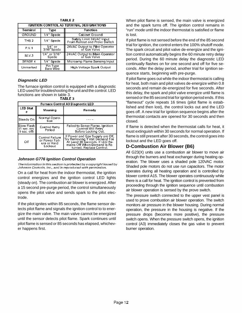
TABLE 2
IGNITION CONTROL A3 TERMINAL DESIGNATIONS
Terminal Type Function
GROUND 1/4� Spade Cabinet Ground
THS 2 1/4� Spade Safety Limit 24VAC InputFrom Rollout and Prove Switch
P.V.1 1/4� or3/16�Spade
24VAC Output to Pilot Operatorof Gas Valve
M.V.3 1/4� or 3/16�Spade
24VAC Output to Main Operatorof Gas Valve
SENSE 4 1/4� Spade Microamp Flame Sensing Input
Unmarked Pin TypeBare Wire High Voltage Spark Output
Diagnostic LED
The furnace ignition control is equipped with a diagnosticLED used for troubleshooting the unit and the control. LEDfunctions are shown in table 3.
TABLE 3
Furnace Control A3 Diagnostic LED
LED State
Meaning Remedy
Steady OnNormal Opera-
tion - - - -
Slow Flash(1 sec. on/5 sec. off)
Control RetryPeriod
Failed to Sense Flame. IgnitionControl Will RetryBefore Locking Out.
Off
Control Failureor Power Fail-ure or HardLockout
If Power and Gas Supply are OK,Try Removing T�stat Demand ForAt Least 30 Seconds. If LED Re-mains Off When Demand Is Re-
turned, Replace Control.
Johnson G776 Ignition Control OperationThe information in this section is protected by a copyright issued byJohnson Controls, Inc., and is reproduced with permission.
On a call for heat from the indoor thermostat, the ignitioncontrol energizes and the ignition control LED lights(steady on). The combustion air blower is energized. Aftera 15 second pre-purge period, the control simultaneouslyopens the pilot valve and sends spark to the pilot elec-trode.
If the pilot ignites within 85 seconds, the flame sensor de-tects pilot flame and signals the ignition control to to ener-gize the main valve. The main valve cannot be energizeduntil the sensor detects pilot flame. Spark continues untilpilot flame is sensed or 85 seconds has elapsed, whichev-er happens first.
When pilot flame is sensed, the main valve is energizedand the spark turns off. The ignition control remains in“run” mode until the indoor thermostat is satisfied or flameis lost.If pilot flame is not sensed before the end of the 85 secondtrial for ignition, the control enters the 100% shutoff mode.The spark circuit and pilot valve de-energize and the igni-tion control automatically begins the 60 minute retry delayperiod. During the 60 minute delay the diagnostic LEDcontinually flashes on for one second and off for five se-conds. After the delay period, another trial for ignition se-quence starts, beginning with pre-purge.If pilot flame goes out while the indoor thermostat is callingfor heat, both main and pilot valves de-energize within 0.8seconds and remain de-energized for five seconds. Afterthis delay, the spark and pilot valve energize until flame issensed or the 85 second trial for ignition period ends. If this“flameout” cycle repeats 16 times (pilot flame is estab-lished and then lost), the control locks out and the LEDgoes off. A new trial for ignition sequence begins after thethermostat contacts are opened for 30 seconds and thenclosed.If flame is detected when the thermostat calls for heat, itmust extinguish within 30 seconds for normal operation. Ifflame is still present after 30 seconds, the control goes intolockout and the LED goes off.
D-Combustion Air Blower (B6)All G23(X) units use a combustion air blower to move airthrough the burners and heat exchanger during heating op-eration. The blower uses a shaded pole 120VAC motor.Shaded pole motors do not use run capacitors. The motoroperates during all heating operation and is controlled byblower control A15. The blower operates continuously whilethere is a call for heat. The ignition control is prevented fromproceeding through the ignition sequence until combustionair blower operation is sensed by the prove switch.The pressure switch connected to the upper vest panel isused to prove combustion air blower operation. The switchmonitors air pressure in the blower housing. During normaloperation, the pressure in the housing is negative. If thepressure drops (becomes more positive), the pressureswitch opens. When the pressure switch opens, the ignitioncontrol (A3) immediately closes the gas valve to preventburner operation.
LENNOXOEMPARTS.COM
3DJH ��
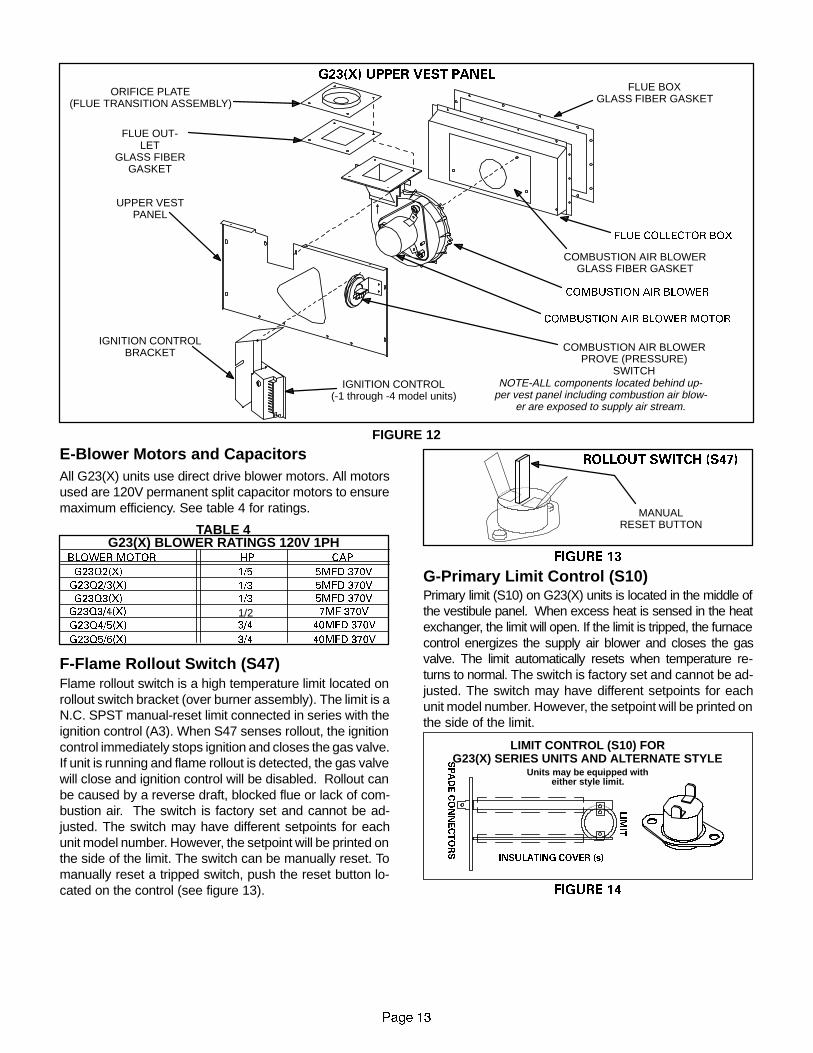
FIGURE 12
G23(X) UPPER VEST PANEL
FLUE COLLECTOR BOX
FLUE BOXGLASS FIBER GASKET
ORIFICE PLATE(FLUE TRANSITION ASSEMBLY)
UPPER VESTPANEL
IGNITION CONTROLBRACKET
COMBUSTION AIR BLOWER
FLUE OUT-LET
GLASS FIBERGASKET
COMBUSTION AIR BLOWER MOTOR
IGNITION CONTROL(-1 through -4 model units)
COMBUSTION AIR BLOWERPROVE (PRESSURE)
SWITCH
COMBUSTION AIR BLOWERGLASS FIBER GASKET
NOTE-ALL components located behind up-per vest panel including combustion air blow-
er are exposed to supply air stream.
E-Blower Motors and CapacitorsAll G23(X) units use direct drive blower motors. All motorsused are 120V permanent split capacitor motors to ensuremaximum efficiency. See table 4 for ratings.
TABLE 4G23(X) BLOWER RATINGS 120V 1PH
BLOWER MOTOR HP
G23Q2/3(X)
G23Q3(X)
CAP
1/3 5MFD 370V
G23Q5/6(X)
G23Q4/5(X) 3/4 40MFD 370V
3/4 40MFD 370V
1/3 5MFD 370V
G23Q2(X) 1/5 5MFD 370V
G23Q3/4(X) 1/2 7MF 370V
F-Flame Rollout Switch (S47)Flame rollout switch is a high temperature limit located onrollout switch bracket (over burner assembly). The limit is aN.C. SPST manual-reset limit connected in series with theignition control (A3). When S47 senses rollout, the ignitioncontrol immediately stops ignition and closes the gas valve.If unit is running and flame rollout is detected, the gas valvewill close and ignition control will be disabled. Rollout canbe caused by a reverse draft, blocked flue or lack of com-bustion air. The switch is factory set and cannot be ad-justed. The switch may have different setpoints for eachunit model number. However, the setpoint will be printed onthe side of the limit. The switch can be manually reset. Tomanually reset a tripped switch, push the reset button lo-cated on the control (see figure 13).
FIGURE 13
ROLLOUT SWITCH (S47)
MANUALRESET BUTTON
G-Primary Limit Control (S10)Primary limit (S10) on G23(X) units is located in the middle ofthe vestibule panel. When excess heat is sensed in the heatexchanger, the limit will open. If the limit is tripped, the furnacecontrol energizes the supply air blower and closes the gasvalve. The limit automatically resets when temperature re-turns to normal. The switch is factory set and cannot be ad-justed. The switch may have different setpoints for eachunit model number. However, the setpoint will be printed onthe side of the limit.
FIGURE 14
INSULATING COVER (s)
LIMIT CONTROL (S10) FORG23(X) SERIES UNITS AND ALTERNATE STYLES
PADECONNECTORS
LIMIT
Units may be equipped witheither style limit.

LENNOXOEMPARTS.COM
Page 14
Units may be equipped with either flush style or extended(masted) limit (figure14). Masted limits may be installedwith limit facing blower or away from blower. This orienta-tion cannot be changed. When removing limit from unit, paycareful attention to its orientation and make sure limit is re-installed facing same direction.
H-Pilot, Spark Electrode, Flame Sensorand Burners (-1 Through -4 Models)
Figure 17 shows the arrangement of pilot, flame sensor,spark electrode and burners. The ignition control uses di-rect spark to ignite the pilot. The pilot ignites the burnersand the burners cross-light. The flame sensor uses flamerectification to sense ignition. The ignition control requiresthat pilot flame must be sensed before the main gas valveis allowed to open. Typically, a 2 to 4 second delay occursbetween the pilot ignition and the main valve opening.
Figure 16 shows the gap between tip of the electrodes andthe burner surface. It is important that the gap be main-tained for consistent ignition of pilot flame.A flame retention ring in the end of each burner is used tomaintain correct flame length and shape and to keep theflame from lifting off the burner head. In addition, the burn-er entrance to each clamshell (Figure 3) is fitted with aflame baffle or corbel to enhance the combustion process.
FIGURE 15
TYPICAL BURNER ASSEMBLY
FIGURE 16
PILOT, SPARK ELECTRODE AND FLAME SENSOR
1/8 (.125) Inch + ”1/32 (.031)
SPARK ELECTRODE
FLAME SENSOR
PILOT
PILOT HOODGAP
SPARK WIRE
SENSE WIRE
FIGURE 17
G23(X)-1, -2, -3 AND -4 MODELS BURNER PILOT/ELECTRODEORIENTATION
view looking at side of burners
ORIFICERETAINER
PRIMARYAIR INLET
BURNERPILOT MOUNTING
BRACKET
FLAME SENSOR
SPARKELECTRODE
PILOT HOOD

LENNOXOEMPARTS.COM
3DJH ��
127( � � 7KH*���;� IXUQDFH FRQWDLQV HOHFWURQLF FRP�
SRQHQWV WKDW DUH SRODULW\ VHQVLWLYH� 0DNH VXUH WKDW WKH
IXUQDFH LV ZLUHG FRUUHFWO\ DQG LV SURSHUO\ JURXQGHG�
DANGERShock hazard.
Disconnect power before servicing. Control is notfield repairable. If control is inoperable, simplyreplace entire control.Can cause injury or death. Unsafe operation willresult if repair is attempted.
I- SureLight Ignition System A3(-5 and -6 models)
All G23(X)-5 and -6 model units are equipped with theLennox SureLight ignition system. The system consistsof ignition control board (figure 21 with control terminaldesignations in table 5) and ignitor (figures 18, 19 and 20.The board and ignitor work in combination to ensure fur-nace ignition and ignitor durability. The SureLight inte-grated board controls all major furnace operations. Theboard also features two LED lights for troubleshootingand two accessory terminals rated at (4) four amps. Seetable 6 for troubleshooting diagnostic codes. Table 7 and8 show jack plug terminal designations. Units equippedwith the SureLight board can be used with either electron-ic or electro-mechanical thermostats without modifica-tion. The SureLight ignitor is made of durable silicon-ni-tride. Ignitor longevity is also enhanced by voltage ramp-ing by the control board. The board finds the lowest igni-tor temperature which will successfully light the burner,thus increasing the life of the ignitor.
)ODPH 6HQVRU
A flame sensor is located on the left side of the burner sup-port. See figures 18, 19 and 20. The sensor is mounted ona bracket in the burner support and the tip protrudes intothe flame envelope of the left-most burner. The sensor isfastened to burner supports and can be removed for ser-vice without removing any part of the burners. During op-eration, flame is sensed by current passed through theflame and sensing electrode. The SureLight control allowsthe gas valve to remain open as long as flame signal issensed.
FIGURE 18
NORMAL FLAME SIGNAL � 0.7 MICROAMPSLOW FLAME SIGNAL $ 0.7 MICROAMPSMINIMUM FLAME SIGNAL $ 0.15 MICROAMPS
3/8”1/4”
19/64”
SENSORIGNITOR
FIGURE 19
IGNITOR
SENSOR
NOTE -Donot removeblower access panel to readSureLight LED lights. A sight glass is provided onthe access panel for viewing.
FIGURE 20
SURELIGHT IGNITOR (I) AND SENSOR (S)LOCATION

LENNOXOEMPARTS.COM
Page 16
SURELIGHT CONTROL BOARD
FIGURE 21
SURELIGHT CONTROL TERMINAL DESIGNATIONSACB COOLACB HEATPARKACB LOWACCTXHOTHTG ACCNEUTRALS24VAC HOT24VAC RTNFLAME SENSE
Blower - Cooling Speed (Line Volt)Blower - Heating Speed (Line Volt)Alternate Blower Speeds (Dead)Continuous Low Speed BlowerAccessory Terminal (Line Volt)120VAC Hot to Transformer120VAC Hot InputHeat Only Accessory (Line Volt)120VAC Neutrals24VAC Hot from Transformer24VAC Return from TransformerFlame Sense Terminal
TABLE 5
TABLE 6
DIAGNOSTIC CODESMAKE SURE TO ID LED’S CORRECTLY: REFER TO INSTALLATION INSTRUCTIONS FOR CONTROL BOARD LAYOUT.
LED #1 LED #2 DESCRIPTIONSIMULTANEOUS
SLOW FLASHSIMULTANEOUS
SLOW FLASHPower - Normal operation
Also signaled during cooling and continues fan.
SIMULTANEOUS FASTFLASH
SIMULTANEOUS FASTFLASH Normal operation - signaled when heating demand initiated at thermostat.
SLOW FLASH ON
Primary or Secondary limit open. Units with board 63K8901 or 24L85: Limit mustclose within 5 trials for ignition or board goes into one hour limit Watchguard.Units with board 56L83 or 97L48: Limit must close within 3 minutes or board
goes into one hour limit Watchguard.
OFF SLOW FLASHPressure switch open or has opened 5 times during a single call for heat; OR:
Blocked inlet/exhaust vent; OR: Condensate line blocked; OR: Pressure switchclosed prior to activation of combustion air blower.
ALTERNATING SLOWFLASH
ALTERNATING SLOWFLASH Watchguard - burners fail to ignite.
SLOW FLASH OFF Flame sensed without gas valve energized.
ON SLOW FLASH Rollout switch open. OR: 9 pin connector improperly attached.
ONONOFF
ONOFFON
Circuit board failure or control wired incorrectly.
FAST FLASH SLOW FLASH Main power polarity reversed. Switch line and neutral.
SLOW FLASH FAST FLASH Low flame signal. Measures below .7 microAmps. Replace flame sense rod.
ALTERNATING FASTFLASH
ALTERNATING FASTFLASH
Improper main ground or line voltage below 75 volts; OR: Broken ignitor; OR:Open ignitor circuit.
NOTE - Slow flash equals 1 Hz (one flash per second). Fast flash equals 3 Hz (three flashes per second). Drop out flame sense current < 0.15 microAmps

LENNOXOEMPARTS.COM
Page 17
TABLE 7
SureLight BOARD J156 (J2) TERMINALDESIGNATIONS
PIN # FUNCTION
1 Ignitor
2 Not Used
3 Ignitor Neutral
4 Combustion Air Blower Line Voltage
5 Not Used
6 Combustion Air Blower Neutral
TABLE 8
SureLight BOARD J58 (J1) TERMINALDESIGNATIONS
PIN # FUNCTION
1 Primary Limit In
2 Gas Valve Common
3 Roll Out Switch Out
4 Gas Valve 24V
5 Pressure Switch In
6 Pressure Switch and Primary Limit Out
7 Not Used
8 Roll Out Switch In
9 Ground
CAUTIONElectrostatic discharge can affect electroniccomponents. Take precautions during furnaceinstallation and service to protect the furnace’selectronic controls. Precautions will help toavoid control exposure to electrostatic dis-charge by putting the furnace, the control andthe technician at the same electrostatic poten-tial. Neutralize electrostatic charge by touchinghand and all tools on an unpainted unit surface,such as the gas valve or blower deck, before per-forming any service procedure.
ELECTROSTATIC DISCHARGE (ESD)Precautions and Procedures
a-Electronic IgnitionOn a call for heat the SureLight control monitors the com-bustion air blower pressure switch. The control will not be-gin the heating cycle if the pressure switch is closed (by-passed). Once the pressure switch is determined to beopen, the combustion air blower is energized. When thedifferential in the pressure switch is great enough, thepressure switch closes and a 15-second pre-purge be-gins. If the pressure switch is not proven within 2-1/2 min-utes, the control goes into Watchguard-Pressure Switchmode for a 5-minute re-set period.After the 15-second pre-purge period, the SureLight igni-tor warms up for 20 seconds after which the gas valveopens for a 4-second trial for ignition. G23X unitsequipped with board 24L85, 56L83 or 63K89: the ignitorstays energized for the first second of the 4-second trial.Units equipped with board 97L48: ignitor stays energizedduring the trial until flame is sensed. If ignition is not provedduring the 4-second period, the control will try four moretimes with an inter purge and warm-up time between trialsof 35 seconds. After a total of five trials for ignition (includ-ing the initial trial), the control goes into Watchguard-Flame Failure mode. After a 60-minute reset period, thecontrol will begin the ignition sequence again.The SureLight control board has an added feature thatprolongs the life of the ignitor. After a successful ignition,the SureLight control utilizes less power to energize the ig-nitor on successive calls for heat. The control continues toramp down the voltage to the ignitor until it finds the lowestamount of power that will provide a successful ignition. Itfinds this by ramping down until the ignitor will not light,then steps up the amount of power by three times. Thisamount of power is used for 255 cycles. On the 256th callfor heat, the control will again ramp down until the lowestpower is determined and the cycle begins again.
b-Fan Time ControlThe fan on time of 45 seconds is not adjustable. Fan offtime (time that the blower operates after the heat demandhas been satisfied) can be adjusted by flipping the dipswitches located on the SureLight integrated control. Theunit is shipped with a factory fan off setting of 90 seconds.Fan off time will affect comfort and is adjustable to satisfyindividual applications. See figure 22.
FIGURE 22
FAN-OFF TIME ADJUSTMENT
To adjust fan-off timing, flip dip switch to desired setting.
60sec. 90sec. 120sec. 180sec.

LENNOXOEMPARTS.COM
3DJH ��
J-Gas ValveThe G23(X) uses a gas valve manufactured by Honeywellor White Rodgers. See figure 23. The valve is internallyredundant to assure safety shut-off. If the gas valve mustbe replaced, the same type valve must be used.24VAC terminals and gas control knob are located on top ofthe valve. All terminals on the gas valve are connected towires from the ignition control. 24V applied to the “PV” termi-nals opens the pilot (-1 through -4 models) and 24V applied tothe “MV” terminals opens the valve on G23X. Inlet and outletpressure taps are located on the valve. A regulator adjust-ment screw (figure 24) is located on the valve.An LPG changeover kit is available from Lennox. The kit in-cludes main and pilot burner orifices, burner corbel plate (Noxonly), and regulator conversion kit.
K-Combustion Air Blower Prove(Pressure) Switch (S64)
G23(X) series units are equipped with a combustion air(pressure) switch located on the vestibule panel. The switchis connected to the combustion air blower housing by meansof a flexible silicon hose. It monitors air pressure in the com-bustion air blower housing. The other side of the pressureswitch is open to atmosphere.
The switch is a single-pole single-throw pressure switchelectrically connected in series with the ignition control. Thepurpose of the switch is to prevent burner operation if thecombustion air blower is not operating.
On start-up, the switch senses that the combustion air blow-er is operating. It closes a circuit to the ignition control whenpressure inside the combustion air blower increases abovethe setpoint. The setpoint is measured in negative incheswater gauge. The pressure sensed by the switch is relativeto atmospheric pressure. If the flue becomes obstructed dur-ing operation, the switch senses a loss of negative pressure(drops below setpoint) and opens the circuit to the ignitioncontrol.The switch setpoint varies with unit model number. Lookfor the setpoint printed on the side of the switch.The switch is factory set and is not field adjustable. It is asafety shut-down control in the furnace and must not bebypassed for any reason.
FIGURE 23
21
2))
HONEYWELL VR8204 SERIES GAS VALVE
GAS VALVE SHOWN IN OFF POSITION
WHITE RODGERS
36E GAS VALVE
GAS VALVESHOWNIN OFF
POSITION
INLET
INLET
FIGURE 24
,1/(735(6685(
7$3
&$3 6&5(:�%ODFN�
$'-867,1* 6&5(:�:KLWH�
635,1*�5HG�
*$6 ,1/(7
35(6685(5(*8/$725
REGULATORCOVERSCREW
$'-867,1*6&5(:�:KLWH�
635,1*
HONEYWELL VR8204 GAS VALVEREGULATOR ADJUSTMENT SCREW LOCATION
WHITE RODGERS 36E GAS VALVEREGULATOR ADJUSTMENT SCREW LOCATION

LENNOXOEMPARTS.COM
3DJH ��
II-PLACEMENT AND INSTALLATIONMake sure unit is installed in accordance with installationinstructions and applicable codes.
A-Fresh Air RequirementsUntil recently, there was no problem in bringing in sufficientamounts of outdoor air for combustion -- infiltration providedall the air that was needed and then some. In today’s homesbuilt with energy conservation in mind, tight construction prac-tices make it necessary to bring in air from outside for com-bustion. Consideration must also be given to the use of ex-haust fans, appliance vents, chimneys and fireplaces be-cause they draw additional air that could be used for combus-tion out of the house. Unless outside air is brought into thehome for combustion, negative pressure (pressure outside isgreater than inside pressure) will build to the point that a downdraft can occur in the furnace vent pipe or chimney. Combus-tion gases can enter the living space creating a potentiallydangerous situation.
The importance of the previous paragraph cannot be over-stated. Users may inadvertently block fresh air intakes af-ter installation.
In the absence of local codes concerning air for combustionand ventilation, the following section outlines guidelines andrecommends procedures for operating G23(X) furnaces in amanner that ensures efficient and safe operation. Specialconsideration must be given to combustion air needs as wellas requirements for exhaust vents and gas piping. A portionof this information has been reprinted with permission fromthe National Fuel Gas Code (ANSI-Z223.1). This reprintedmaterial is not the complete and official position of the ANSIon the referenced subject, which is represented only by thestandard in its entirety.
In Canada, refer to the standard CAN/CGA-B149.1 and -B149.2 installation codes.
Combustion Air Requirements
&$87,21
Insufficient combustion air can cause headaches,nausea, dizziness or asphyxiation. Excessive ex-posure to contaminated combustion air will resultin safety and performance related problems.Avoid exposure to the following substances in thecombustion air supply:Permanent wave solutions;Chlorinated waxes and cleaners;Chlorine base swimming pool chemicals;Water softening chemicals;De-icing salts or chemicals;Carbon tetrachloride;Halogen type refrigerants;Cleaning solvents (such as perchloroethylene);Printing inks, paint removers, varnishes, etc.;Hydrochloric acid;Cements and glues;Antistatic fabric softeners for clothes dryers; andMasonry acid washing materials.
All gas-fired appliances require air to be used for the com-bustion process. If sufficient amounts of combustion air arenot available, the furnace or other appliance will operate inan inefficient and unsafe manner. Enough air must be pro-vided to meet the needs of all fuel-burning appliances, aswell as appliances such as exhaust fans which force air outof the home. When fireplaces, exhaust fans, or clothes dry-ers are used at the same time as the furnace, much more airis required to ensure proper combustion and to prevent adown-draft situation. Insufficient amounts of air also causeincomplete combustion which can result in carbon monox-ide. The requirements for providing air for combustion andventilation depend largely on whether the furnace is installedin an unconfined or confined space.
Unconfined SpaceAn unconfined space is an area such as a basement orlarge equipment room with a volume greater than 50 cubicfeet per 1,000 Btu per hour of the combined input rating ofall appliances installed in that space. This space also in-cludes adjacent rooms which are not separated by a door.Though an area may appear to be unconfined, it might benecessary to bring in outdoor air for combustion if thestructure does not provide enough air by infiltration. If thefurnace is located in a building of tight construction withweather stripping and caulking around the windows anddoors, follow the procedures outlined for using air from theoutside for combustion and ventilation.
Confined SpaceA confined space is an area with volume less than 50 cubicfeet per 1,000 Btu per hour of the combined input rating of allappliances installed in that space. This definition includesfurnace closets or small equipment rooms.

LENNOXOEMPARTS.COM
3DJH ��
When the furnace is installed so that supply ducts carry air
circulated by the furnace to areas outside the space con-
taining the furnace, the return air must be handled by ducts
which are sealed to the furnace casing and which termi-
nate outside the space containing the furnace. This is es-
pecially important when the furnace is mounted on a plat-
form in a confined space such as a closet or small equip-
ment room. Even a small leak around the base of the unit
at the platform or at the return air duct connection can
cause a potentially dangerous negative pressure condi-
tion. Air for combustion and ventilation can be brought into
the confined space either from inside the building or from
outside.
Air from Inside
If the confined space housing the furnace adjoins space
categorized as unconfined, air can be brought in by provid-
ing two permanent openings between the two spaces.
Each opening must have a minimum free area of 1 square
inch per 1,000 Btu per hour of the total input rating of all
gas-fired equipment in the confined space. Each opening
must be at least 100 square inches. One opening shall be
within 12 inches of the top of the enclosure and one open-
ing within 12 inches of the bottom (See figure 25).
EQUIPMENT IN CONFINED SPACEALL AIR FROM INSIDE
FIGURE 25
NOTE-Each opening shall have a free areaof at least one squareinch per 1,000 Btu per hour of the total input rating of all equip-ment in the enclosure, but not less than 100 square inches.
CHIMNEY ORGAS VENT
WATERHEATER
OPENINGS(To Adjacent
Room)
G23(X)FURNACE
Air from OutsideIf air from outside is brought in for combustion and ventila-tion, the confined space shall be provided with two perma-nent openings. One opening shall be within 12 inches ofthe top of the enclosure and one within 12 inches of thebottom. These openings must communicate directly or byducts with the outdoors or spaces (crawl or attic) that freelycommunicate with the outdoors or indirectly through verti-cal ducts. Each opening shall have a minimum free area of1 square inch per 4,000 Btu per hour of total input rating ofall equipment in the enclosure (See figures 26 and 27).When communicating with the outdoors through horizon-tal ducts, each opening shall have a minimum free area of1 square inch per 2,000 Btu per total input rating of allequipment in the enclosure (See figure 28).
EQUIPMENT IN CONFINED SPACEALL AIR FROM OUTSIDE
(Inlet Air from Crawl Space andOutlet Air to Ventilated Attic)
NOTE-The inlet and outlet air openings shall each have a freearea of at least one square inch per 4,000 Btu per hour of thetotal input rating of all equipment in the enclosure.
VENTILATION LOUVERS(Each end of attic)
OUTLETAIR WATER
HEATER
INLETAIR
CHIMNEYOR GASVENT
VENTILATIONLOUVERS
(For unheatedcrawl space)
FIGURE 26
G23FURNACE
EQUIPMENT IN CONFINED SPACEALL AIR FROM OUTSIDE
(All Air Through Ventilated Attic)
NOTE-The inlet and outlet air openings shall each have a freearea of at least one square inch per 4,000 Btu per hour of thetotal input rating of all equipment in the enclosure.
CHIMNEYOR GASVENT
WATERHEATER
OUTLETAIR
VENTILATION LOUVERS(Each end of attic)
INLET AIR(Ends 12� above
bottom)
FIGURE 27
G23(X)FURNACE

LENNOXOEMPARTS.COM
3DJH ��
EQUIPMENT IN CONFINED SPACEALL AIR FROM OUTSIDE
OUTLET AIR
INLET AIR
WATERHEATER
CHIMNEYOR GASVENT
FIGURE 28
NOTE-Each air duct opening shall have a free area of at leastone square inch per 2,000 Btu per hour of the total input ratingof all equipment in the enclosure. If the equipment room is lo-cated against an outside wall and the air openings communi-cate directly with the outdoors, each opening shall have a freearea of at least one square inch per 4,000 Btu per hour of thetotal input rating of all other equipment in the enclosure.
G23(X)FURNACE
When ducts are used, they shall be of the same cross-sec-tional area as the free area of the openings to which theyconnect. The minimum dimension of rectangular air ductsshall be no less than 3 inches. In calculating free area, theblocking effect of louvers, grilles, or screens must be con-sidered. If the design and free area of protective covering isnot known for calculating the size opening required, it maybe assumed that wood louvers will have 20 to 25 percentfree area and metal louvers and grilles will have 60 to 75percent free area. Louvers and grilles must be fixed in theopen position or interlocked with the equipment so that theyare opened automatically during equipment operation.
B-Flue Venting RequirementsG23(X) series furnaces must be vented in compliance withall local codes, the venting tables provided in this manualand these instructions.
The G23(X) series units have been classified as fan as-sisted Category I type furnaces when vertically vented inaccordance with the latest edition of ANSI Z21.47 CentralFurnace Standard. The definition of a fan assisted Catego-ry I type furnace is an appliance equipped with an integralmechanical means to either draw or force products of com-bustion through the combustion chamber and/or heat ex-changer.
The vent sizing tables in this manual have been extractedfrom the National Fuel Gas Code (NFPA 54 / ANSI Z223.1)and are provided for convenience to serve as a guidelinefor proper vent installation. Proper application, termina-tion, construction and location of vents must conform to lo-cal codes having jurisdiction. In the absence of localcodes, the NFGC serves as the defining document.
Refer to the tables and the venting information contained inthese instructions for proper sizing and installation of theventing system.
The G23(X) series units have the following flue collarsizes: -50 unit, 3” diameter; -75 and -100 units, 4” diame-ter; and -125 & -150 units, 5” diameter. Use this informa-tion in conjunction with the provided venting tables to prop-erly size the vent or vent connector that attaches to the fur-nace flue collar.
Venting Using a Masonry Chimney
The following additional requirements apply when a linedmasonry chimney is being used to vent a G23(X) furnace:
A Category I appliance must never be connected to achimney that is servicing a solid fuel appliance. If a fire-place chimney flue is used to vent this appliance, the fire-place opening must be permanently sealed.

LENNOXOEMPARTS.COM
3DJH ��
FIGURE 29
COMMON VENTING USING TILE-LINED INTERIOR MASONRYCHIMNEY AND COMBINED VENT CONNECTOR
G23OTHER
APPLIANCE
VENTCONNECTOR
(Double-walled,single-walled, orinsulated single-
walled pipe)
MINI. LENGTH = AS SHORTAS PRACTICAL.
INTERIORTILE-LINED MASONRY
CHIMNEY
NOTE - CHIMNEY MUST BEPROPERLY SIZED PER THE PRO-
VIDED VENTING TABLES OR LINEDWITH LISTED METAL LINING SYSTEM.
PERMANENTLY SEALEDFIREPLACE OPENING
A chimney with one or more sides exposed to the outsideof the structure is considered to be an exterior chimney. AType B or listed chimney lining system passing through anunused masonry chimney flue is not considered to be ex-posed to the outdoors.
Masonry chimneys used to vent Category I central fur-naces must be either tile-lined or lined with a listed metallining system or dedicated gas vent. Unlined masonrychimneys are prohibited.
A fan assisted furnace may be commonly vented into anexisting lined internal masonry chimney provided:
1 - The chimney is currently serving at least one draft-hood equipped appliance.
2 - The vent connectors and chimney are sized in accor-dance with the provided venting tables.
SINGLE APPLIANCE VENTING OF A FAN ASSISTEDFURNACE INTO A TILE-LINED MASONRY CHIMNEY(INTERIOR OR OUTSIDE WALL) IS PROHIBITED. THECHIMNEY MUST FIRST BE LINED WITH EITHER TYPE“B” VENT OR AN INSULATED SINGLE WALL FLEXIBLEVENT LINING SYSTEM, SIZED IN ACCORDANCE WITHTHE PROVIDED VENTING TABLES.
See figures 29 and 30 for common venting.
A Type “B” vent or masonry chimney liner shall terminateabove the roof surface with a listed cap or a listed roof as-sembly in accordance with the terms of their respectivelistings and the vent manufacturer’s instructions.
Do not install a manual damper, barometric draft regulator,or flue restrictor between the furnace and the chimney.
If type “B” double-wall vent is used inside a chimney, noother appliance can be vented into the chimney. Outer wallof type “B” vent pipe must not be exposed to flue products.
Insulation for the flexible vent pipe must be an encapsu-lated fiberglass sleeve recommended by the flexible ventpipe manufacturer. See figure 30.
The space between liner and chimney wall shouldNOT be insulated with puffed mica or any other loosegranular insulating material.
FIGURE 30
COMMON VENTING USINGMETAL-LINED MASONRY CHIMNEY
4 IN. MIN.(102mm)
5 FT.(1.5m)
MINIMUM
MIN. LENGTH -- ASSHORT AS PRACTICAL
SEALED
PERMANENTLYSEALED FIREPLACE
OPENING
EXTERIORCHIMNEY WITH“B” VENT ORINSULATED
FLEXIBLE VENTPIPE.
LENNOXOEMPARTS.COM
3DJH ��
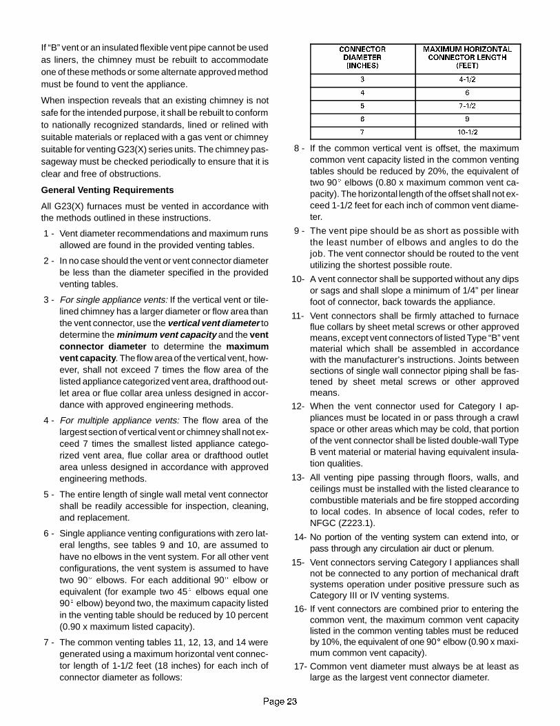
If “B” vent or an insulated flexible vent pipe cannot be usedas liners, the chimney must be rebuilt to accommodateone of these methods or some alternate approved methodmust be found to vent the appliance.
When inspection reveals that an existing chimney is notsafe for the intended purpose, it shall be rebuilt to conformto nationally recognized standards, lined or relined withsuitable materials or replaced with a gas vent or chimneysuitable for venting G23(X) series units. The chimney pas-sageway must be checked periodically to ensure that it isclear and free of obstructions.
General Venting Requirements
All G23(X) furnaces must be vented in accordance withthe methods outlined in these instructions.
1 - Vent diameter recommendations and maximum runsallowed are found in the provided venting tables.
2 - In no case should the vent or vent connector diameterbe less than the diameter specified in the providedventing tables.
3 - For single appliance vents: If the vertical vent or tile-lined chimney has a larger diameter or flow area thanthe vent connector, use the vertical vent diameter todetermine the minimum vent capacity and the ventconnector diameter to determine the maximumvent capacity . The flow area of the vertical vent, how-ever, shall not exceed 7 times the flow area of thelisted appliance categorized vent area, drafthood out-let area or flue collar area unless designed in accor-dance with approved engineering methods.
4 - For multiple appliance vents: The flow area of thelargest section of vertical vent or chimney shall not ex-ceed 7 times the smallest listed appliance catego-rized vent area, flue collar area or drafthood outletarea unless designed in accordance with approvedengineering methods.
5 - The entire length of single wall metal vent connectorshall be readily accessible for inspection, cleaning,and replacement.
6 - Single appliance venting configurations with zero lat-eral lengths, see tables 9 and 10, are assumed tohave no elbows in the vent system. For all other ventconfigurations, the vent system is assumed to havetwo 90E elbows. For each additional 90E elbow orequivalent (for example two 45E elbows equal one90E elbow) beyond two, the maximum capacity listedin the venting table should be reduced by 10 percent(0.90 x maximum listed capacity).
7 - The common venting tables 11, 12, 13, and 14 weregenerated using a maximum horizontal vent connec-tor length of 1-1/2 feet (18 inches) for each inch ofconnector diameter as follows:
CONNECTORDIAMETER(INCHES)
MAXIMUM HORIZONTALCONNECTOR LENGTH
(FEET)
3 4-1/2
4 6
5 7-1/2
6 9
7 10-1/2
8 - If the common vertical vent is offset, the maximumcommon vent capacity listed in the common ventingtables should be reduced by 20%, the equivalent oftwo 90E elbows (0.80 x maximum common vent ca-pacity). The horizontal length of the offset shall not ex-ceed 1-1/2 feet for each inch of common vent diame-ter.
9 - The vent pipe should be as short as possible withthe least number of elbows and angles to do thejob. The vent connector should be routed to the ventutilizing the shortest possible route.
10- A vent connector shall be supported without any dipsor sags and shall slope a minimum of 1/4” per linearfoot of connector, back towards the appliance.
11- Vent connectors shall be firmly attached to furnaceflue collars by sheet metal screws or other approvedmeans, except vent connectors of listed Type “B” ventmaterial which shall be assembled in accordancewith the manufacturer’s instructions. Joints betweensections of single wall connector piping shall be fas-tened by sheet metal screws or other approvedmeans.
12- When the vent connector used for Category I ap-pliances must be located in or pass through a crawlspace or other areas which may be cold, that portionof the vent connector shall be listed double-wall TypeB vent material or material having equivalent insula-tion qualities.
13- All venting pipe passing through floors, walls, andceilings must be installed with the listed clearance tocombustible materials and be fire stopped accordingto local codes. In absence of local codes, refer toNFGC (Z223.1).
14- No portion of the venting system can extend into, orpass through any circulation air duct or plenum.
15- Vent connectors serving Category I appliances shallnot be connected to any portion of mechanical draftsystems operation under positive pressure such asCategory III or IV venting systems.
16- If vent connectors are combined prior to entering thecommon vent, the maximum common vent capacitylisted in the common venting tables must be reducedby 10%, the equivalent of one 90E elbow (0.90 x maxi-mum common vent capacity).
17- Common vent diameter must always be at least aslarge as the largest vent connector diameter.

LENNOXOEMPARTS.COM
3DJH ��
18- In no case, shall the vent connector be upsized morethan two consecutive table size diameters over thesize of the drafthood outlet or flue collar outlet.
19- A manual damper, barometric draft regulator or fluerestrictor must not be installed between furnace andany chimney.
20- When connecting this appliance to an existing dedi-cated or common venting system, the venting system,must be inspected for signs of corrosion, and generalcondition. The sizing of the vent system must be re-viewed and conform to these instructions and the pro-vided venting tables. If the existing system is in conflictwith these requirements, the venting system must beresized.
TABLE 9CAPACITY OF TYPE B DOUBLE-WALL VENTS WITH TYPE B DOUBLE-WALL CONNECTORS
SERVING A SINGLE CATEGORY I APPLIANCE
Vent and Connector Diameter - D (inches)
HeightH
LateralL
3 Inch 4 Inch 5 Inch 6 InchH
(feet)L
(feet) Appliance Input Rating in Thousands of Btu Per Hour(feet) (feet)
MIN MAX MIN MAX MIN MAX MIN MAX
0 0 78 0 152 0 251 0 375
62 13 51 18 97 27 157 32 232
64 21 49 30 94 39 153 50 227
6 25 46 36 91 47 149 59 223
0 0 84 0 165 0 276 0 415
82 12 57 16 109 25 178 28 263
85 23 53 32 103 42 171 53 255
8 28 49 39 98 51 164 64 247
0 0 88 0 175 0 295 0 447
102 12 61 17 118 23 194 26 289
105 23 57 32 113 41 187 52 280
10 30 51 41 104 54 176 67 267
0 0 94 0 191 0 327 0 502
2 11 69 15 136 20 226 22 339
15 5 22 65 30 130 39 219 49 3305
10 29 59 40 121 51 206 64 315
15 35 53 48 112 61 195 76 301
0 0 97 0 202 0 349 0 540
2 10 75 14 149 18 250 20 377
205 21 71 29 143 38 242 47 367
2010 28 64 38 133 50 229 62 351
15 34 58 46 124 59 217 73 337
20 48 52 55 116 69 206 84 322
0 0 100 0 213 0 374 0 587
2 9 81 13 166 14 283 18 432
5 21 77 28 160 36 275 45 421
30 10 27 70 37 150 48 262 59 405
15 33 64 44 141 57 249 70 389
20 56 58 53 132 66 237 80 374
30 NR NR 73 113 88 214 104 346
NOTE: Single appliance venting configurationswith zero lateral lengths are assumed to have no elbows in the vent system. For all other vent configura -tions, theventsystem isassumed tohave two90Eelbows. For eachadditional90Eelbowor equivalent (for example two45Eelbowsequalone90Eelbow)beyond two, the maximum capacity listed in the venting table should be reduced by 10 percent (0.90 x maximum listed capacity).

LENNOXOEMPARTS.COM
3DJH ��
TABLE 10CAPACITY OF TYPE B DOUBLE-WALL VENTS WITH SINGLE-WALL METAL CONNECTORS
SERVING A SINGLE CATEGORY I APPLIANCEVent and Connector Diameter - D (inches)
HeightH
LateralL
3 Inch 4 Inch 5 Inch 6 InchH
(feet)L
(feet) Appliance Input Rating in Thousands of Btu Per Hour(feet) (feet)
MIN MAX MIN MAX MIN MAX MIN MAX
0 38 77 59 151 85 249 126 373
62 39 51 60 96 85 156 123 231
64 NR NR 74 92 102 152 146 225
6 NR NR 83 89 114 147 163 220
0 37 83 58 164 83 273 123 412
82 39 56 59 108 83 176 121 261
85 NR NR 77 102 107 168 151 252
8 NR NR 90 95 122 161 175 243
0 37 87 57 174 82 293 120 444
102 39 61 59 117 82 193 119 287
105 52 56 76 111 105 185 148 277
10 NR NR 97 100 132 171 188 261
0 36 93 56 190 80 325 116 499
2 38 69 57 136 80 225 115 337
15 5 51 63 75 128 102 216 144 3265
10 NR NR 95 116 128 201 182 308
15 NR NR NR NR 158 186 220 290
0 35 96 54 200 78 346 114 537
2 37 74 56 148 78 248 113 375
205 50 68 73 140 100 239 141 363
2010 NR NR 93 129 125 223 177 344
15 NR NR NR NR 155 208 216 325
20 NR NR NR NR 186 192 254 306
0 34 99 53 211 76 372 110 584
2 37 80 55 164 76 281 109 429
5 49 74 72 157 98 271 136 417
30 10 NR NR 91 144 122 255 171 39730
15 NR NR 115 131 151 239 208 377
20 NR NR NR NR 181 223 246 357
30 NR NR NR NR NR NR NR NR
NOTE: Single appliance venting configurationswith zero lateral lengths are assumed to have no elbows in the vent system. For all other vent configura -tions, theventsystem isassumed tohave two90Eelbows. For eachadditional90Eelbowor equivalent (for example two45Eelbowsequalone90Eelbow)beyond two, the maximum capacity listed in the venting table should be reduced by 10 percent (0.90 x maximum listed capacity).

LENNOXOEMPARTS.COM
3DJH ��
TABLE 11CAPACITY OF TYPE B DOUBLE-WALL VENTS WITH TYPE B DOUBLE-WALL CONNECTORS
SERVING TWO OR MORE CATEGORY I APPLIANCESVENT CONNECTOR CAPACITY
Vent ConnectorVent and Connector Diameter - D (inches)
VentHeight
ConnectorRise 3 Inch 4 Inch 5 Inch 6 InchHeight
H(feet)
RiseR
(feet)Appliance Input Rating in Thousands of Btu Per Hour
(feet) (feet)MIN MAX MIN MAX MIN MAX MIN MAX
1 22 37 35 66 46 106 58 164
6 2 23 41 37 75 48 121 60 1836
3 24 44 38 81 49 132 62 199
1 22 40 35 72 49 114 64 176
8 2 23 44 36 80 51 128 66 195
3 24 47 37 87 53 139 67 210
1 22 43 34 78 49 123 65 189
10 2 23 47 36 86 51 136 67 2060
3 24 50 37 92 52 146 69 220
1 21 50 33 89 47 142 64 220
15 2 22 53 35 96 49 153 66 2355
3 24 55 36 102 51 163 68 248
1 21 54 33 99 46 157 62 246
20 2 22 57 34 105 48 167 64 259
3 23 60 35 110 50 176 66 271
1 20 62 31 113 45 181 60 288
30 2 21 64 33 118 47 190 62 29930
3 22 66 34 123 48 198 64 309
TABLE 12CAPACITY OF TYPE B DOUBLE-WALL VENTS WITH TYPE B DOUBLE-WALL CONNECTORS
SERVING TWO OR MORE CATEGORY I APPLIANCESCOMMON VENT CAPACITY
VentCommon Vent Diameter - D (inches)
VentHeight 4 Inch 5 Inch 6 Inch 7 InchHeight
H(feet)
Appliance Input Rating in Thousands of Btu Per Hour(feet)
FAN + FAN FAN + NAT FAN + FAN FAN + NAT FAN + FAN FAN + NAT FAN + FAN FAN + NAT
6 92 81 140 116 204 161 309 248
8 101 90 155 129 224 178 339 275
10 110 97 169 141 243 194 367 299
15 125 112 195 164 283 228 427 352
20 136 123 215 183 314 255 475 394
30 152 138 244 210 361 297 547 459

LENNOXOEMPARTS.COM
3DJH ��
TABLE 13CAPACITY OF TYPE B DOUBLE-WALL VENT WITH SINGLE-WALL METAL CONNECTORS
SERVING TWO OR MORE CATEGORY I APPLIANCESVENT CONNECTOR CAPACITY
Vent ConnectorVent and Connector Diameter - D (inches)
VentHeight
ConnectorRise 3 Inch 4 Inch 5 Inch 6 InchHeight
H(feet)
RiseR
(feet)Appliance Input Rating in Thousands of Btu Per Hour
(feet) (feet)MIN MAX MIN MAX MIN MAX MIN MAX
1 NR NR NR NR NR NR NR NR
6 2 NR NR NR NR NR NR 168 1826
3 NR NR NR NR 121 131 174 198
1 NR NR 79 87 116 138 177 214
15 2 NR NR 83 94 121 150 185 230
3 NR NR 87 100 127 160 193 243
1 47 60 77 110 113 175 169 278
30 2 50 62 81 115 117 185 177 29030
3 54 64 85 119 122 193 185 300
TABLE 14CAPACITY OF TYPE B DOUBLE-WALL VENTS WITH SINGLE-WALL METAL CONNECTORS
SERVING TWO OR MORE CATEGORY I APPLIANCESCOMMON VENT CAPACITY
VentCommon Vent Diameter - D (inches)
VentHeight 4 Inch 5 Inch 6 Inch 7 InchHeight
H(feet)
Appliance Input Rating in Thousands of Btu Per Hour(feet)
FAN + FAN FAN + NAT FAN + FAN FAN + NAT FAN + FAN FAN + NAT FAN + FAN FAN + NAT
6 89 78 136 113 200 158 304 244
8 98 87 151 126 218 173 331 269
10 106 94 163 137 237 189 357 292
15 121 108 189 159 275 221 416 343
20 131 118 208 177 305 247 463 383
30 145 132 236 202 350 286 533 446
Removal of Unit from Common Venting System
In the event that an existing furnace is removed from aventing system commonly run with separate gas ap-pliances, the venting system is likely to be too large toproperly vent the remaining attached appliances. The fol-lowing test should be conducted while each appliance is inoperation and the other appliances not in operation remainconnected to the common venting system. If the ventingsystem has been installed improperly, the system must becorrected as outlined in the previous section.
1 - Seal any unused openings in the common ventingsystem.
2 - Visually inspect the venting system for proper sizeand horizontal pitch and determine there is no block-age or restriction, leakage, corrosion and other defi-ciencies which could cause an unsafe condition.
3 - Insofar as is practical, close all building doors and win-dows and all doors between the space in which the ap-pliances remaining connected to the common ventingsystem are located and other spaces of the building.Turn on clothes dryers and any appliances not con-nected to the common venting system. Turn on any ex-
haust fans, such as range hoods and bathroom ex-hausts, so they will operate at maximum speed. Do notoperate a summer exhaust fan. Close fireplace damp-ers.
4 - Following the lighting instruction, place the appliancebeing inspected in operation. Adjust thermostat so ap-pliance will operate continuously.
5 - Test for spillage at the draft hood relief opening after 5minutes of main burner operation. Use the flame of amatch or candle, or smoke from a cigarette, cigar orpipe.
6 - After it has been determined that each appliance re-maining connected to the common venting systemproperly vents when tested as outlined above, returndoors, windows, exhaust fans, fireplace dampers andany other gas burning appliance to their previouscondition of use.
7 - If improper venting is observed during any of theabove tests, the common venting system must becorrected. The common venting system should be re-sized to approach the minimum size as determined byusing the appropriate tables in appendix G in the cur-rent standards of the National Fuel Gas Code ANSIZ223-1.

LENNOXOEMPARTS.COM
3DJH ��
Horizontal Venting
SIDE WALL VENTING KIT WIRING
C
L1
L2120VAC
M
L1 MN T1 T2 T3
W R Y G
W
G
R
Y
24 VACTHERMOSTAT
THERMOSTAT CONNECTIONSTERMINAL IN FURNACE
JUNCTION BOX
RELAY
CK-43 CONTROL BOX
PRESSURESWITCH
SWGPOWERVENTERMOTOR
FIGURE 31
T
FIELD INSTALLED WIRING
FACTORY INSTALLED WIRING
NO
2
1
3
5
4
This furnace is design certified by the American GasAssociation for horizontal venting through an outside wallonly with the use of a Field Controls Company ModelSWG-4L side wall venting kit available from Lennox Deal-er Service Center. No other Field brand venting kit or anyother manufacturer’s venting kit is acceptable. Horizontalventing of this furnace without the use of the above statedkit is prohibited. See figure 31 for field wiring of side wallhorizontal venting kit.When horizontally vented, minimum clearance for ter-mination from electric meters, gas meters, regulators andrelief equipment is 4 ft. (1.2m).III-START-UPA-Preliminary and Seasonal Checks1 - Inspect electrical wiring, both field and factory installed
for loose connections. Tighten as required.2 - Check voltage at disconnect switch. Voltage must be
within range listed on the nameplate. If not, consult thepower company and have voltage condition correctedbefore starting unit.
B-Heating Start-Up
FOR YOUR SAFETY READ BEFORE LIGHTING
WARNINGShock and burn hazard.G23(X)-1 through -4 model units are equipped withan electronic spark ignition system. Do not attemptto light manually.
WARNINGShock and burn hazard.G23(X)-5 and -6 model units are equipped with theSureLight ignition system. Do not attempt to lightmanually..
WARNINGDo not use this furnace if any part has been under-water. Inspect the furnace and replace any part ofthe control system and any gas control which hasbeen under water.
CAUTIONBefore attempting to perform any service or main-tenance, turn the electrical power to unit OFF atdisconnect switch.
WARNINGIf overheating occurs or if gas supply fails to shutoff, shut off the manual gas valve to the appliancebefore shutting off electrical supply.
BEFORE LIGHTING smell all around the appliance areafor gas. Be sure to smell next to the floor because somegas is heavier than air and will settle on the floor.Use only your hand to push in or turn the gas control knob.Never use tools. If the knob will not push in or turn by hand,do not try to repair it, call a qualified service technician.Force or attempted repair may result in a fire or explosion.G23(X) -1 through -4 model units are equipped with an inter-mittent pilot ignition system. Do not attempt to manually lightpilot on these furnaces. Each time thermostat calls for heat,the pilot will be automatically lit. The pilot does not burn whenthere is no call for heat.
How To Operate Gas Valve (Figure 33)
WARNINGIf you do not follow these instructions exactly, afire or explosion may result causing propertydamage, personal injury or loss of life.
Gas Valve Operation (Figure 33)
1 - STOP! Read the safety information at the beginningof this section.
2 - Set thermostat to lowest setting. See figure 32.3 - Turn off all electrical power to appliance.
THERMOSTATS
FIGURE 32

LENNOXOEMPARTS.COM
3DJH ��
4 - This appliance is equipped with an ignition devicewhich automatically lights the furnace. Do not try tolight the furnace by hand.
5 - Remove upper access panel.6 - On Honeywell VR8204 gas valves, turn knob on gas
valve clockwise to OFF. For White Rodgers 36Egas valves, move switch to OFF. Do not force. See fig-ure 33.
21
2))
FIGURE 33
HONEYWELL VR8204 SERIES GAS VALVE
GAS VALVE SHOWN IN OFF POSITION
WHITE RODGERS36E GAS VALVE
GAS VALVESHOWNIN OFF
POSITION
7 - Wait five (5) minutes to clear out any gas. If you thensmell gas, STOP! Immediately call your gas supplierfrom a neighbor’s phone. Follow the gas supplier’sinstructions. If you do not smell gas go to next step.
8 - For Honeywell VR8204 gas valves, turn knob on gasvalve counterclockwise to ON. For White Rodg-ers 36E gas valves, move switch to ON.
9 - Replace upper access panel.
10- Turn on all electrical power to unit.
11- Set thermostat to desired setting.
127(� �:KHQ XQLW LV LQLWLDOO\ VWDUWHG� VWHSV � WKURXJK ��
PD\ QHHG WR EH UHSHDWHG WR SXUJH DLU IURP SLORW OLQH�
12- If the appliance still will not operate, follow the instruc-tions “To Turn Off Gas To Unit” and call your servicetechnician or gas supplier.
To Turn Off Gas To Unit
1 - Set thermostat to lowest setting.
2 - Turn off all electrical power to unit if service is to beperformed.
3 - Remove upper access panel.
4 - On Honeywell VR8204 gas valves, turn knob on gasvalve clockwise to OFF. For White Rodgers 36Egas valves, move switch to OFF. Do not force.
5 - Replace upper access panel.
C-Safety or Emergency Shutdown
Turn off unit power. Close manual and main gas
valves.
D-Extended Period Shutdown
Turn off thermostat or set to “UNOCCUPIED” mode. Closeall gas valves (both internal and external to unit) to guaran-tee no gas leak into combustion chamber. Turn off powerto unit. All access panels, covers and vent caps must be inplace and secured.
IV-HEATING SYSTEM SERVICE CHECKSA-A.G.A CertificationAll units are A.G.A. design certified without modifications.Refer to the G23(X) Operation and Installation InstructionManual Information.
B-Gas Piping
Gas supply piping should not allow more than
0.5�W.C. drop in pressure between gas meter and
unit. Supply gas pipe must not be smaller than unit
gas connection. See table 16 for gas pipe capacity.
Compounds used on gas piping threaded joints should beresistant to action of liquefied petroleum gases.
C-Testing Gas Piping
IMPORTANTIn case emergency shutdown is required, turn offthe main shut-off valve and disconnect the mainpower to unit. These controls should be properlylabeled by the installer.
When pressure testing gas lines, the gas valve must bedisconnected and isolated. Gas valves can be damaged ifsubjected to more than 0.5psig (14” W.C.). See figure 34. Ifthe pressure is equal to or less than 0.5psig (14”W.C.), usethe manual shut-off valve before pressure testing to iso-late furnace from gas supply.
FIGURE 34
GAS PIPING TEST PROCEDURE (Typical)
1/8” NPTPLUGGED
TAP
MANUAL MAIN
SHUT-OFF
VALVE
UNION
CONDENSATETRAP
TEE
CAP
GAS VALVE
GAS VALVE WILL NOT HOLD
TEST PRESSURE IN EXCESS
OF 0.5 PSIG (14�W.C.)

LENNOXOEMPARTS.COM
3DJH ��
FIGURE 35
GROUNDJOINTUNION
LEFT SIDE PIPING(STANDARD)
RIGHT SIDE PIPING
AUTOMATICGAS VALVE
MANUALMAIN SHUT-OFF
VALVE
1/8” NPTPLUGGED
TAP
GROUNDJOINTUNION
MANUALMAIN SHUT-OFF
VALVE
1/8” NPTPLUGGED
TAP
AUTOMATICGAS VALVE
When checking piping connections for gas leaks, use pre-ferred means. Kitchen detergents can cause harmful corro-sion on various metals used in gas piping. Use of a specialtyGas Leak Detector is strongly recommended. It is availablethrough Lennox under part number 31B2001. See Corp.8411-L10, for further details.Do not use matches, candles, flame or any other source ofignition to check for gas leaks.
D-Check Manifold PressureAfter line pressure has been checked and adjusted, checkmanifold pressure. Move pressure gauge to outlet pres-sure tap located on unit gas valve (GV1). Checks of man-ifold pressure are made as verification of proper regulatoradjustment. Manifold pressure for the G23(X) can be mea-sured at any time the gas valve is open and is supplying gasto the unit. Normal manifold pressure for natural gas units is3.5 in. w.c. For LP gas the correct manifold pressure is 10.0in. w.c.
IMPORTANTFor safety, connect a shut-off valve between themanometer and the gas tap to permit shut off ofgas pressure to the manometer.
Operating Pressure (outlet) in. W.C.
TABLE 15
GAS VALVE REGULATION
3.5 + 0.3Natural
L.P. 10.0 + 0.5
Unit (Fuel)
The gas valve is factory set and should not require ad-
justment. See table 15.
Manifold Adjustment Procedure:1 - Connect a test gauge to outlet pressure tap on gas
valve. Start unit and allow 5 minutes for unit to reachsteady state.
2 - While waiting for the unit to stabilize, notice the flame.Flame should be stable and should not lift from burner.Natural gas should burn blue. L.P. gas should burnmostly blue with some orange streaks.
3 - After allowing unit to stabilize for 5 minutes, recordmanifold pressure and compare to values given intable 15.
IMPORTANTFor safety, shut unit off and remove manometeras soon as an accurate reading has been ob-tained. Take care to replace pressure tap plug.
E-Testing Gas Supply PressureWhen testing supply gas pressure, connect test gauge toinlet pressure tap (field provided). See figure 35. Checkgas line pressure with unit firing at maximum rate. Lowpressure may result in erratic operation or underfire. Highpressure can result in permanent damage to gas valve oroverfire. For natural gas units, operating pressure at unitgas connection must be between 4.5” W.C. and 13.0” W.C.For L.P. gas units, operating pressure at unit gas connec-tion must be between 10.5” W.C. and 13.0” W.C.
On multiple unit installations, each unit should be checkedseparately, with and without units operating. Supply pres-sure must fall within range listed in previous paragraph.

LENNOXOEMPARTS.COM
Page 31
TABLE 16GAS PIPE CAPACITY - FT3/HR (kL/HR)
Nominal Internal Length of Pipe-Feet(m)NominalIron Pipe Size-Inches(mm)
InternalDiameter
-Inches(mm)10
(3.048)20
(6.096)30
(9.144)40
(12.192)50
(15.240)60
(18.288)70
(21.336)80
(24.384)90
(27.432)100
(30.480)
1/4(6.35)
.364(9.246)
43(1.13)
29(.82)
24(.68)
20(.57)
18(.51)
16(.45)
15(.42)
14(.40)
13(.37)
12(.34)
3/8(9.53)
.493(12.522)
95(2.69)
65(1.84)
52(1.47)
45(1.27)
40(1.13)
36(1.02)
33(.73)
31(.88)
29(.82)
27(.76)
1/2(12.7)
.622(17.799)
175(4.96)
120(3.40)
97(2.75)
82(2.32)
73(2.07)
66(1.87)
61(1.73)
57(1.61)
53(1.50)
50(1.42)
3/4(19.05)
.824(20.930)
360(10.19)
250(7.08)
200(5.66)
170(4.81)
151(4.28)
138(3.91)
125(3.54)
118(3.34)
110(3.11)
103(2.92)
1(25.4)
1.049(26.645)
680919.25)
465(13.17)
375(10.62)
320(9.06)
285(8.07)
260(7.36)
240(6.80)
220(6.23)
205(5.80)
195(5.52)
1-1/4(31.75)
1.380(35.052)
1400(39.64)
950(26.90)
770(21.80)
660(18.69)
580(16.42)
530(15.01)
490(13.87)
460(13.03)
430(12.18)
400(11.33)
1-1/2(38.1)
1.610(40.894)
2100(59.46)
460(41.34)
1180(33.41)
990(28.03)
900(25.48)
810(22.94)
750(21.24)
690(19.54)
650(18.41)
620(17.56)
2(50.8)
2.067(52.502)
3950(111.85)
2750(77.87)
2200(62.30)
1900(53.80)
1680(47.57)
1520(43.04)
1400(39.64)
1300(36.81)
1220(34.55)
1150(32.56)
2-1/2(63.5)
2.469(67.713)
6300(178.39)
4350(123.17)
3520(99.67)
3000(84.95
2650(75.04)
2400(67.96)
2250(63.71)
2050(58.05)
1950(55.22)
1850(52.38)
3(76.2)
3.068(77.927)
11000(311.48)
7700(218.03)
6250(176.98)
5300(150.07)
4750(134.50)
4300(121.76)
3900(110.43)
3700(104.77)
3450(97.69)
3250(92.03)
4(101.6)
4.026(102.260)
23000(651.27)
15800(447.39)
12800(362.44)
10900(308.64)
9700(274.67)
8800(249.18)
8100(229.36)
7500(212.37)
7200(203.88)
6700(189.72)
NOTE-Capacity given in cubic feet of gas per hour (kilo liters of gas per hour) and based on 0.60 specific gravity gas.
F- Proper Gas Flow (Approximate)Furnace should operate at least 5 minutes before check-ing gas flow. Determine time in seconds for two revolu-tions of gas through the meter. (Two revolutions assuresa more accurate time.) Divide by two and compare to timein table 17 below. Adjust manifold pressure on gas valveto match time needed.
NOTE- To obtain accurate reading, shut off all othergas appliances connected to meter.
TABLE 17
GAS METER CLOCKING CHART
Seconds for One Revolution
G23(X)Unit
Natural LPG23(X)Unit 1 cu ft
Dial2 cu ftDial
1 cu ftDial
2 cu ftDIAL
-50 72 144 180 360
-75 48 96 120 240
-100 36 72 90 180
-125 29 58 72 144
-150 24 48 60 120
Natural-1000 btu/cu ft LP-2500 btu/cu ft
G-High Altitude DeratePressure regulator may need to be adjusted, dependingon altitude. See table 18 for proper pressure regulator set-ting.
TABLE 18Manifold Absolute Pressure (Outlet) in. w.c.
FUELALTITUDE
FUEL0 - 4500 4501 - 5500 5501 - 6500 6501 - 7500
NAT. GAS 3.5 3.3 3.1 3.0
L.P. GAS 10.0 10.0 10.0 10.0
A natural to LP/propane gas changeover kit is required toconvert unit. Refer to the installation instructions suppliedwith the changeover kit for conversion procedure.
The pressure switch is factory set. No adjustment is nec-
essary. The G23-50/75 units use the factory pressure
switch from 0 to 7500 feet. G23-100/125 and G23-150
units require a high altitude pressure switch for units
installed above 5000 feet. Order Lennox part number
97J50 for G23-100/125 and 18J35 for G23-150.
H-Flame Signal
A microamp DC meter is needed to check the flame signal
on the ignition control.
Flame (microamp) signal is an electrical current which passes
from the furnace control through the sensor during unit opera-
tion. Current passes from the sensor through the flame to
ground to complete a safety circuit.

LENNOXOEMPARTS.COM
FIGURE 36
TRANSDUCER(PART #78H5401)
FIGURE 37
STATIC PRESSURETEST
MANOMETER
G23(X) UNIT
3DJH ��
To Measure Flame Signal-G776 Ignition Control:
A transducer (Part#78H5401 availablefrom Lennox RepairParts) is required tomeasure flamesignal. See figure 36.The transducer convertsmicroamps to volts on a1:1 conversion. If the flame signal should read 0.15-0.25microamps, a reading of 0.15-0.25 volts should be read onthe meter. See table 19 for correct microamp reading.
A digital readout meter must be used. The transducer plugsinto most meters.
TABLE 19
FLAME SIGNAL MICROAMPS
G23(X) -1, -2, -3 Normal 0.25G23(X) 1, 2, 3and -4 models Minimum 0.15
G23(X) 5 and 6Normal �0.7
G23(X) -5 and -6models
Low $0.7models
Minimum 0.15
1 - Set the volt meter to the DC voltage scale. Insert trans-ducer into the VDC and common inputs. Observe cor-rect polarities. Failure to do so results in negative (-)values.
2 - Turn off supply voltage to control.3 - Disconnect flame sensor lead from terminal of ignition
control.4 - Connect (+) lead of transducer to ignition control sen-
sor connection.5 - Connect (-) lead of the transducer to sensor wire.6 - Turn supply voltage on and close thermostat contacts
to cycle system.7 - When unit lights read voltage on meter display. Re-
member 1 DC volt = 1 DC microamp. See table 19 forcorrect microamp reading.
WARNINGFire and explosion hazard.These instructions MUST be followed exactly.Can cause a fire or explosion resulting in propertydamage, personal injury or loss of life.
Flame signal may rise above 0.5 microamps for the firstfew seconds after ignition and then level off within therange.
V-TYPICAL OPERATING CHARACTERISTICS
A-Blower Operation and AdjustmentNOTE- The following is a generalized procedure anddoes not apply to all thermostat controls.
1 - Blower operation is dependent on thermostat controlsystem.
2 - Generally, blower operation is set at thermostat sub-base fan switch. With fan switch in ON position, bloweroperates continuously. With fan switch in AUTO posi-tion, blower cycles with demand or runs continuouslywhile heating or cooling circuit cycles.
3 - In all cases, blower and entire unit will be off when thesystem switch is in OFF position.
B-Temperature RiseTemperature rise for G23(X) units depends on unit input,blower speed, blower horsepower and static pressure asmarked on the unit rating plate. The blower speed must beset for unit operation within the range of “AIR TEMP. RISEqF” listed on the unit rating plate.
To Measure Temperature Rise:
1 - Place plenum thermometers in the supply and re-
turn air plenums. Locate supply air thermometer
in the first horizontal run of the plenum where it
will not pick up radiant heat from the heat ex-
changer.
2 - Set thermostat to highest setting. After furnace
reaches equilibrium, (approximately 15 minutes)
check firing rate.
3 - After plenum thermometers have reached their
highest and steadiest readings, subtract the two
readings. The difference should be in the range
listed on the unit rating plate. If the temperature is
too low, decrease blower speed. If temperature is
too high, increase blower speed to reduce temper-
ature. To change blower speed taps see the Blow-
er Speed Taps section in this manual.
C-External Static Pressure1 - Measure tap locations as shown in figure 37.
2 - Punch a 1/4� diameter
hole in supply (between
furnace and coil) and re-
turn (between furnace
and any add on such as
electronic air cleaner) air
plenums. Insertmanome-
ter hose flush with inside
edge of hole or insulation. Seal around the hose
with permagum. Connect the zero end of the ma-
nometer to the discharge (supply) side of the sys-
tem. On ducted systems, connect the other end of
manometer to the return duct as above. For sys-
temswith non-ducted returns, leave the other end
of the manometer open to the atmosphere.
3 - With only the blowermotor running and the evap-
orator coil dry, observe the manometer reading.
Adjust blower motor speed to deliver the air de-
sired according to the job requirements.
4 - External static pressure drop must not be more
than 0.5� W.C.
5 - Seal around the hole when the check is complete.

LENNOXOEMPARTS.COM
3DJH ��
To Remove Blower:
1. Turn off line voltage power.Unplug J69 from P69 locatedon blower deck.
2. Disconnect thermostat wiringconnections by removing lowvoltage terminal strip.
3. Disconnect J20/P20 located onblower deck.
4. Disconnect J43/P43 fromblow-er motor.
5. Loosen screws (2) and removecontrol box from unit. Holesare slotted so screws do notneed to be removed.
6. Remove screws (2) and re-move blower from unit.
FIGURE 38
G23(X) BLOWER REMOVAL
4
5
26
3
1
5
D-Blower Speed Taps Leadless Motors(-1, -2, -3 and -4 Models)
Blower speed tap selection is accomplished by changing thetaps at the blower motor harness connector. Disconnect har-ness connector from motor to expose speed selectors.Blower speed selections are listed in table 20.To Change Blower Speed:1 - Turn off electric power to furnace.2 - Remove blower access door. See figure 1.3 - Disconnect blower motor harness from motor.4 - Pull harness connector and wires through blower ac-
cess panel opening.5 - Select desired speeds for heating and cooling. (Red =
heating, Black = cooling, White = common). See table20.
6 - Depress harness connector tab to release wire termi-nal. Select connector location for new speed (refer tounit wiring diagram). Insert wire terminal until it is se-curely in place. See figure 39.
7 - Replace harness connector to motor .TABLE 20
FIGURE 39
DEPRESS TAB TO RELEASEWIRE TERMINAL. SELECT CON-NECTOR LOCATION FOR NEWSPEED (REFER TO UNIT WIRINGDIAGRAM). INSERT WIRE UNTILIT IS SECURELY IN PLACE.
MOTOR
HARNESSCONNECTOR
BLOWER SPEED TAP SELECTIONLEADLESS MOTORS
*NOTE-Q3(X)-100 furnaces use a 4 tap motor with lowspeed permanently blocked off so it cannot be used. Donot attempt to operate unit on low speed tap.
E-Blower Speed Taps Leaded Motors-5 and -6 Models
Blower speed tap changes are made on the SureLightcontrol board. See figure 21. Unused taps must be se-cured on dummy terminals ”PARK M1” and or ”PARK M2”on the SureLight board. The heating tap is connected tothe ”ACB HEAT ” terminal and the cooling tap is connectedto the ”ACB COOL” terminal. The continuous blower tap isconnected to the ”ACB LOW” terminal.To change existing heat tap, turn off power then switch outspeed tap on ”ACB HEAT” with tap connected to ”PARKM1” or ”PARK M2”. See table 21 for blower motor tap col-ors for each speed.

LENNOXOEMPARTS.COM
3DJH ��
TABLE 21
VI-MAINTENANCEA-FiltersRetainers for optional return air filter are shown in figure40.
),*85( ��
%27720 5(7851 ),/7(5
FURNACEBASE BOTTOM
5($5 ),/7(5 &/,3
RETURN AIROPENING
6,'( ),/7(5 &/,36 ���
FURNACEFRONT
FURNACEBACK
At the beginning of each heating season, the systemshould be checked as follows:1. Filters should be inspected monthly and must be
cleaned or replaced when dirty to assure proper fur-nace operation.
2. Optional foam filters available for the G23(X) can bewashed with water and mild detergent. When dry, theyshould be sprayed with filter handicoater prior to rein-stallation. Filter handicoater is RP Products coatingno. 418 and is available as Lennox part no. P-8-5069.
3. If replacement is necessary, order Lennox part no.31J8101 for 14 X 25 inch filter for G23(X)-50, and 75units, P-8-7822 for 16 X 25 inch filter for Q3(X)-100units, and P-8-7831 for 20” x 25 ” filters used onQ3/4(X)-100, Q3/4(X)-125, Q4/5(X)-75, Q4/5(X)-100,Q5/6(X)-125 and Q5/6(X)-150 units.
B-Cleaning Heat Exchanger and Burners
NOTE-Use papers or protective covering in front of fur-nace while cleaning furnace.
Cleaning the heat exchanger requires a steel spring“snake,” a reversible drill and a vacuum cleaner. The steelspring snake may be constructed by purchasing a 4 ft. longby 1/4” diameter steel wire cable and a 1/4” diameter wirebrush. These items are available at a hardware store. In-sert wire end of brush into the open end of the spring cable.Crimp the cable around the brush so that the brush is se-
cured and will not come off during cleaning. Attach the oth-er end of the cable to the reversible drill to complete thetool for cleaning the heat exchanger. See figure 3 for partsarrangement when disassembling furnace.1 - Turn off both electrical and gas power supplies to fur-
nace.2 - Remove flue pipe and top cap from unit. Mark and dis-
connect wiring from pressure switch and ignition con-trol (-1 through -4 model units). Remove ignition con-trol and pressure switch from upper vestibule panel.
3 - Remove upper vestibule panel to expose the combus-tion air blower.
FIGURE 41
G23(X) BURNER ANDHEAT EXCHANGER REMOVAL
G23(X) HEAT EXCHANGER
BURNER BOX ASSEMBLY
4 - Remove three screws securing the combustion airblower. Carefully remove the combustion air blower toavoid damaging blower gasket. If gasket is damaged, itmust be replaced to prevent leakage.
5 - Remove collector box located behind combustion airblower. Care must be taken to avoid damaging the col-lector box gasket. If the gasket is damaged it must bereplaced to prevent leakage.
6 - Mark then disconnect wires from gas valve and rolloutswitch.
7 - Disconnect gas supply piping. Remove four screwssecuring the burner manifold assembly to the lowervestibule panel and remove the assembly from theunit.
8 - For NOx units only, remove the screws holding theflame baffles in the heat exchanger clam shells. Care-fully remove each baffle from each heat exchangersection. To avoid damaging baffles, turn baffles 90Ebe-fore pulling out through heat exchanger outlet.
IMPORTANTMark each baffle so that they are returned to theproper heat exchanger section.

LENNOXOEMPARTS.COM
3DJH ��
G23(X) FLAME BAFFLES(NOx UNITS ONLY)
FLAME BAFFLE
TO REMOVE BAFFLE: REMOVESCREW. ROTATE BAFFLE AS SHOWNAND REMOVE FROM HEAT EXCHANG-ER
FIGURE 42
9 - Insert brush end of cable snake into top of one of theheat exchanger openings. DO NOT FORCE CABLEINTO HEAT EXCHANGER. Once the cable has beeninserted, operate drill on slow speed. Move the cablein and out of the heat exchanger section three or fourtimes or until sufficient cleaning is accomplished. Re-verse drill and slowly work cable out of opening.
10- Repeat procedure for each heat exchanger section.11- When the top heat exchanger sections are complete,
place brush end of cable snake into the bottom openingsof each of the heat exchanger sections. Clean the bottomopening as described in step 9.
12- Remove cable from heat exchanger. Use a vacuum toremove debris knocked loose during cleaning fromeach heat exchanger section.
13- Attach the exhaust end (positive pressure) of thevacuum to the top of the heat exchanger sections.Any loose debris will be forced to the bottom of theheat exchanger section. Vacuum debris from bot-tom openings.
14- Replace collector box and combustion air blower.Check gaskets for damage. Damaged seals must bereplaced to avoid heat exchanger leaks. Replace allscrews to the collector box and combustion air blower.Leaving off screws may cause leaks.
15- Replace upper vestibule panel, top cap, pressureswitch and ignition control.
16- Clean burner by running a vacuum with a soft brush at-tachment over face of burners. Visually inspect inside ofburners and crossovers for any blockage caused by for-eign matter. Remove any blockage.
17- For NOX units, replace flame baffles in each heat ex-changer section. DO NOT BEND baffles. Bafflesshould sit on the bottom of each heat exchanger sec-tion.
18- Replace burner / manifold assembly onto lower vesti-bule panel.
19- Reconnect wires to ignition control (-1 through -4 mod-el units), pressure switch, roll-out switch, gas valve andcombustion air blower. Refer to unit wiring diagram.
20- Reconnect vent pipe to combustion blower outlet.
21- Reconnect gas supply piping.
22- Turn on power and gas supply to unit.
23- Set thermostat and check for proper operation.
24- Check all piping connections, factory and field, for gasleaks. Use a leak detecting solution or other preferredmeans.
CAUTIONSome soaps used for leak detection are corrosiveto certain metals. Carefully rinse piping thorough-ly after leak test has been completed. Do not usematches, candles, flame or other sources of igni-tion to check for gas leaks.
25- If a leak is detected, shut gas and electricity off andrepair leak.
26- Repeat steps 23 and 24 until no leaks are detected.
27- Replace front access panel.
C-Supply Air Blower1 - Check and clean blower wheel.
2 - Motors usedon the LennoxG23(X) series units are
permanently lubricated and need no further lu-
brication.
D-Flue and ChimneyFlue must conform to all AGA/GAMA venting require-ments. Flue pipe deteriorates from the inside out and mustbe disconnected in order to check thoroughly. Check fluepipe, chimney and all connections for tightness and tomake sure there is no blockage or leaks.
E-Electrical1 - Check all wiring for loose connections.
2 - Check for correct voltage.
3 - Check amp-draw on blower motor.

LENNOXOEMPARTS.COM
3DJH ��
CONTROLBOX
GASVALVE
FLAMEROLL-OUT
SWITCH/,0,7
%/$&.
%52:1
),(/' ,167$//(' &/$66 ,, ��9 92/7$*(
),(/' ,167$//(' /,1( 92/7$*(
TYPICAL G23(X) FIELD WIRING DIAGRAM(-5 and -6 MODELS SHOWN)
/� 1
)86('',6&211(&76:,7&+
�)851,6+('%<,167$//(5�
75$16)250(5
DOORINTERLOCK
SWITCH
COMBUSTIONAIR BLOWER
COMBUSTIONAIR PROVE
SWITCHFIELD
MAKE-UPBOX
*1'
-��:+,7(
TO ACCESSORY IF USED.(ELECTRONIC AIR CLEANER)
IF NOT NEEDED, DO NOT INSTALLACCESSORY WIRE IN J69.* :< 5
685(/,*+7 &21752/
THERMOSTAT
TO COMPRESSORCONTACTOR
*: 5 <
&
7KHUPRVWDW
&2035(6625
&20021
G23(X)Furnace Condensing
Unit
G23(X) and CONDENSING UNITTHERMOSTAT DESIGNATIONS
(Refer to specific thermostat and outdoor unit.)
COMMON
POWER
HEAT
INDOOR BLOWER
COOLING
R
W1
Y
G
C
R
W1
Y
G
C

LENNOXOEMPARTS.COM
3DJH ��
��
�
�
�
�� �
OPERATION SEQUENCE-G23(X) -1, -2, -3 and -4 MODELS
1 - Whendisconnect is closed, 120V is routed throughdoor interlock switch (S51) to feed the line voltageside of the blower control (A3) and transformer T1primary. Door interlock switchmust be closed forA3 and T1 to receive voltage.
2 - T1 supplies 24VAC to terminal �24VAC� on A3. Inturn, terminal �R� of A3 supplies 24VAC to termi-nal �RC� of the indoor thermostat (not shown).
3 - When there is a call for heat, W1 of the thermostatenergizes W of the furnace control with 24VAC.
4 - CAB of the blower control energizes the combus-tion air blower (B6). When the combustion airblower nears full speed, combustion air proveswitch (S18) closes.
5 - When S18 closes, assuming the flame rolloutswitch (S47) primary limit (S10) and secondarylimits (S21) are closed, the ignition control opensthe pilot valve and begins spark.
6 - When flame is sensed, spark stops andmain valveopens to light main burners.
7 - After 45 seconds, blower control (A3) energizesthe indoor blower.
8 - When heat demand is satisfied,W1 of the thermo-stat de-energizes W of the furnace control and thefurnace control immediately de-energizes the gasvalve. The combustion air blower immediatelystops. Also, the indoor blower runs for a desig-nated period (90-330 seconds) as set by jumper onblower control.

LENNOXOEMPARTS.COM
Page 38
CHECK:1-UNIT POWER
2-INTERLOCK SWITCH3-TRANSFORMER4-LIMIT SWITCH
START
IS24VAC ACROSS
R & T?
YES
JUMPER ACROSSSCREWS R & G
YES
DOES UNITOPERATE?
NO
NO
ISBLOWER
RUNNING ON HIGHSPEED?
NO IS120VAC ACROSS
N1 & A?
REPLACEBCC
NOYES
YES
CHECK BLOWERWIRING AND
BLOWER
IS120VAC ACROSS
N1 & ACC?
NOREPLACEBCC
YES
JUMPER ACROSSR &W
(REMOVE R & G JUMPER)
ISCOMB. AIR BLOWER
ON?
NO
REPLACEBCC
NO IS120VAC ACROSS
N1 & CAB?
CHECKCOMBUSTIONAIR BLOWER
YES
YES ARE BURNERSLIT?
NO
CHECK:1-COMBUSTION AIR BLOWER
2-IGNITION CONTROL3-GAS VALVE
4-IGNITOR5-LIMIT SWITCHES6-PROVE SWITCHYES
IS BLOWERRUNNING ON LOW
SPEED, 45 SEC.AFTER FURNACE
LIGHTS?
NOIS
120VAC ACROSSN1 & H?
YES
IS24VAC ACROSS
T & V?
REPLACEBCC
NO
NO
CHECKWIRING
YESIS120VAC ACROSS
N1 & ACC?
YES
REMOVER & W
JUMPER
AFTERTHE SELECTEDTIME, DOES THEBLOWER TURN
OFF?
YES NO
YES
REPLACEBCC
END OF TEST
BCCTROUBLESHOOTING
FLOWCHART
NO
REPLACEBCC
CHECK BLOWERWIRING AND
BLOWER
FIGURE 43
CHECK CIRCUIT BREAKER.RESET IF NECESSARY.
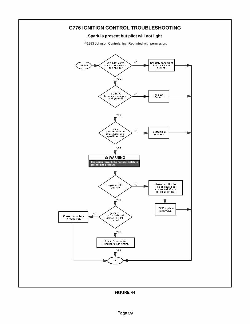
LENNOXOEMPARTS.COM
3DJH ��
START
YES
NO
G776 IGNITION CONTROL TROUBLESHOOTING
Spark is present but pilot will not light
.1993 Johnson Controls, Inc. Reprinted with permission.
Are pilot valveconnections correct
and secure?
Securely connect atterminal 1 and
ground.
Is 24VACbetween terminals 1
and ground?
ReplaceControl.
Is inletgas pressure permanufacturer�sspecifications?
Correct gaspressure.
WARNING
Explosion Hazard. Do not use match totest for gas pressure.
Is gas at pilotburner?
Make sure pilot lineis not kinked orobstructed. Checkfor clean orifice.
If OK, replacepilot valve.
Is sparkgap 0.1 inch andlocated in pilot
stream?
Correct or replacepilot burner.
Shield from drafts.Check for clean orifice.
END
YES
YES
YES
YES
YES
NO
NO
NO
NO
FIGURE 44

LENNOXOEMPARTS.COM
3DJH ��
START
YES
NO
G776 IGNITION CONTROL TROUBLESHOOTING
No spark and system will not work
.1993 Johnson Controls, Inc. Reprinted with permission.
Is 24VACbetween THS 2and ground?
Check the following:1) 120VAC Supply2) Transformer3) Thermostat
Open thermostat contacts for30 seconds. Close contactsand wait 2 seconds longer
than prepurge (17 sec. total).
Is sparkpresent now?
System was is lockout. Determine the Cause:1) Flameout cycling.
2) Internal malfunction.3) Flame present when it should not be.
Did pilot remainlit from previous
cycle?
Replace gasvalve.
Turn OFFsupply voltage
Is high voltagecable securely
connected to sparktransformer?
Connect securelythen turn ONsupply voltage.
Is high voltagecable brittle, burnt
or cracked?
Replace cable.
Is spark electrodeceramic cracked?
Replace pilotburner.
Is spark gap 0.1inch and located inpilot gas stream?
Correct or replacepilot burner. TurnON supply voltage.
ENDReplacecontrol.
YES
YES
NO
NO
NO
YES
NO
YES
NO
YES
NO
YES
FIGURE 45

LENNOXOEMPARTS.COM
3DJH ��
START
YES
NO
G776 IGNITION CONTROL TROUBLESHOOTING
Pilot lights but main valve will not come on
.1993 Johnson Controls, Inc. Reprinted with permission.
Does sparkstay on for more than5 seconds after pilot
lights?
Is 24VACbetween terminals3 and ground?
Replacecontrol.
Correctgas
pressure.
Correctwiring.
Replacemain valve.
Is mainvalve wiring securelyconnected to terminals
3 and ground?
Is inletgas pressure permanufacturer�sspecifications?
Make sure sensor cableand high voltage cableare separated and notwrapped around anypipe or accessories.
Is mainvalve wiring securelyconnected to terminals
4 and ground?
Connectsecurely.
Replacesensor.
Is sensorceramic cracked?
Correct.
Correct.
Is sensor cablegrounded out?
Is sensoror sensor connectorshorted to a metal
surface?
Does sensor cablelack continuity
or good insulation?
Replacecable.
Disconnect main valve lead fromterminal 3 and sensor cable from
terminal 4. Observing correct polarity,connect DC microammeter between
terminalof sensor cable and terminal 4.
If system still fails, clean pilotassembly, or replace flamesensor, orifice, or control.
Is DC current0.15 microamps
or greater?
Replacecontrol.
END
NO
NO
YES
NO
NO
YES
YES
FIGURE 46
YES
YES
YES
YES
NO
NO
NOYES
NO
YESNO

LENNOXOEMPARTS.COM
Page 42
2
3
5
6
4
1
7
8
2
OPERATION SEQUENCE-G23(X) -5 and -6 MODELS WITH SURELIGHT CONTROL1 - When there is a call for heat, W1 of the thermostat en-
ergizes W of the furnace control with 24VAC.
2 - S10 primary limit switch and S47 rollout switch are
closed. Call for heat can continue.
3 - Surelight control energizes combustion air blower B6.Combustion air blower runs until S18 combustion airprove switch closes (switch must close within 2-1/2minutes or control goes into 5 minute WatchguardPressure Switch delay). Once S18 closes, a 15-sec-ond pre-purge follows.
4 - Surelight control energizes ignitor. A 20-secondwarm-up period begins.
5 - Gas valve opens for a 4-second trial for ignition.6 - Flame is sensed, gas valve remains open for the heat
call.7 - After 45-second delay, Surelight control energizes in-
door blower B3.8 - When heat demand is satisfied, W1 of the indoor ther-
mostat de-energizes W of the Surelight control whichde-energizes the gas valve. Combustion air blowerB6 continues a 5-second post-purge period, and in-door blower B3 completes a selected OFF time delay.

LENNOXOEMPARTS.COM
3DJH ��
SURELIGHT CONTROLHEATING SEQUENCE OF
OPERATIONNORMAL HEATING MODE ABNORMAL HEATING MODE
CONTROL SELF-CHECK OKAY?
BURNER OFF?(CONTINUOUS FLAME CHECK)
NORMAL OPERATION:LED #1 -- SLOW FLASHLED #2 -- SLOW FLASH
YES
YES
YES
GAS VALVE OFF. COMBUSTION AIR BLOWER OFF.INDOOR BLOWER DELAY OFF.
LED #1 ONLED #2 ON
(RESET CONTROL BY TURNING MAIN POWER OFF.)
POLARITY REVERSED.LED #1 -- FAST FLASHLED #2 -- SLOW FLASH
POWER ON
COMBUSTION AIR BLOWER ON FOR 1 SECOND.
TURN INDUCER ON FOR 1SECOND.
IS POLARITY REVERSED?
ROLLOUT SWITCH CLOSED?
THERMOSTAT CALLS FOR HEAT:LED #1 -- FAST FLASHLED #2 -- FAST FLASH
IS COMBUSTION AIRPRESSURE SWITCH OPEN?
GAS VALVE OFF. COMBUSTION AIR BLOWER OFF.INDOOR BLOWER OFF WITH DELAY.LED #1 -- ON. LED #2 -- SLOW FLASH.
SEQUENCE HOLDS UNTIL ROLLOUT SWITCH CLOSES.
GAS VALVE OFF. COMBUSTION AIR BLOWER ON.INDOOR BLOWER ON HEATING SPEED.
LED #1 -- SLOW FLASHLED #2 -- OFF
GAS VALVE OFF.COMBUSTION AIR BLOWER OFF.
INDOOR BLOWER OFF WITH DELAY.LED #1 OFF
LED #2 SLOW FLASH(Sequence holds until pressure switchcloses or thermostat resets control.)
NO
NO
YES
NO
IS THEREPROPER GROUND?
IS VOLTAGEABOVE 75 VOLTS?
LOW VOLTAGE SIGNAL AT LED HOLDSUNTIL VOLTAGE RISES ABOVE 75 VOLTS.
NOYESNO
SIGNAL IMPROPERGROUND AT LED.SIGNAL HOLDSUNTIL UNIT IS
PROPERLYGROUNDED.
NO
NO
IS COMBUSTION AIR BLOWER ENERGIZED?(HTG ACC TERMINAL IS ENERGIZED WITH C.A.B.)
HAS COMBUSTION AIR PRESSURESWITCH CLOSED IN 2.5 MINUTES?
YES
YES PRESSURE SWITCH IS IN WATCHGUARD MODE.GAS VALVE OFF. COMBUSTION AIR BLOWER OFF.
INDOOR BLOWER OFF WITH DELAY.LED #1 -- OFF. LED #2 -- SLOW FLASH.
IS 5-MINUTE RESET PERIOD COMPLETE?
NO
15-SECOND COMBUSTION AIR BLOWER PREPURGEINITIATED BY CLOSED PRESSURE SWITCH.
YES
YES
CONTINUED NEXT PAGE
YES
GAS VALVE OFF. COMBUSTION AIR BLOWER ON.INDOOR BLOWER ON.
LED #1 ALTERNATING FAST FLASHLED#2 ALTERNATING FAST FLASHCHECK FOR BROKEN IGNITOR OR
OPEN IGNITOR CIRCUIT

LENNOXOEMPARTS.COM
Page 44
HEATING SEQUENCE CONTINUEDNORMAL HEATING MODE ABNORMAL HEATING MODE
FLAME RECTIFICATION CURRENT CHECKCAN FLAME BE PROVEN WITHIN 4
SECONDS AFTER GAS VALVE OPENS?(>0.15 microamps)
NOFLAME PRESENT?
INDOOR BLOWER ON DELAY BEGINS. AFTER 45SECOND DELAY, ACB HEAT SPEED TERMINAL IS
ENERGIZED. ACC. TERMINAL IS ENERGIZED.
PRIMARY AND SECONDARY LIMITSWITCHES CLOSED?
COMBUSTION AIR PRESSURESWITCH CLOSED?
LOW FLAME SIGNAL(Does not affect operation of control)
LED #1 -- SLOW FLASHLED #2 -- FAST FLASH
GAS VALVE DE-ENERGIZED.COMBUSTION AIR BLOWER DE-ENERGIZED.
INDOOR BLOWER ON UNTIL SWITCH CLOSES.LED #1 -- SLOW FLASH. LED #2 -- ON.
IS LIMIT SWITCH CLOSED?
GAS VALVE DE-ENERGIZED.COMBUSTION AIR BLOWER ON.
INDOOR BLOWER OFF WITH DELAYLED #1 -- OFF. LED #2 -- SLOW FLASH.
HAS CAB SWITCH CLOSED IN 2.5 MINUTES?
15-SECOND COMBUSTION AIR BLOWER PREPURGEINITIATED BY CLOSED PRESSURE SWITCH.
YES
IGNITOR WARM-UP -- 20 SECONDS.
YES
4-SECOND TRIAL FOR IGNITION.GAS VALVE OPENS. BOARD 24L85, 56L83, 63K8901:IGNITOR ENERGIZED FOR 1 SECOND AFTER VALVE
OPENS. BOARD 97L48: IGNITOR ENERGIZESTHROUGH OUT 4 SECOND TRIAL.
YESFLAME STABILIZATION PERIOD.
GAS VALVE OFF. COMBUSTION AIR BLOWER ON.INDOOR BLOWER OFF.
HAS CONTROL FAILED TO SENSE FLAME FORFIVE CONSECUTIVE TRIES DURING A SINGLE
HEAT DEMAND?
NO
WATCHGUARD MODE. GAS VALVE OFF.COMBUSTION AIR BLOWER OFF.
INDOOR BLOWER OFF WITH DELAYLEDs SIGNAL WATCHGUARD FAILURE CODE.
IS 60-MINUTE RESET PERIOD COMPLETE?
YES
YES
NO
4 SECONDS
YES
HAS CONTROL RESET IGNITIONSEQUENCE FOUR TIMES?
YES
NO
FLAME SIGNAL ABOVE 0.7 MICROAMPS?NO
YES
YES
HAS PRIMARY LIMIT RESET?(See table 6 DIAGNOSTIC CODES for limit reset operation).
NO
YES
NO
YES
ROLLOUT SWITCH CLOSED?
GAS VALVE OFF. COMBUSTION AIR BLOWER OFF.INDOOR BLOWER OFF WITH DELAY.LED #1 -- ON. LED #2 -- SLOW FLASH.
SEQUENCE HOLDS UNTIL ROLLOUT SWITCH CLOSES.
NO
YES
YESNO
THERMOSTAT DEMAND SATISFIED.
LED #1 & #2 SIMULTANEOUS SLOW FLASHES.
COMB. AIR BLOWER CONTINUES 5-SECONDPOST PURGE AFTER T’STAT DEMAND IS SATISFIED.
HTG ACC. TERM. IS DE-ENERGIZED. INDOOR AIRBLOWER COMPLETES SELECTED “OFF” DELAY BE-FORE SHUTTING OFF. ACC. TERM. DE-ENERGIZED.
YES
YES
YES
NO
5-MINUTE PRESSURE SWITCHWATCHGUARD MODE.
YES

LENNOXOEMPARTS.COM
Page 45
SURELIGHT CONTROLCOOLING SEQUENCE OF OPERATION
NORMAL COOLING MODE ABNORMAL COOLING MODE
IGNITION CONTROL MAIN POWER ON.
CONTROL SELF DIAGNOSTIC CHECK.IS CONTROL OPERATING NORMALLY?
YES
SIGNAL POLARITY REVERSED AT LED.
POWER ON
GAS VALVE OFF. COMBUSTION AIR BLOWER OFF.INDOOR BLOWER OFF WITH NORMAL DELAY.
SIGNAL CIRCUIT BOARD FAILURE AT LED.INTERRUPT MAIN POWER TO RESET CONTROL.
YES
TURN INDUCER ON FOR 1 SECOND.
IS POLARITY REVERSED?
ROLLOUT SWITCH MONITORED CONTINUOUSLY.IS ROLLOUT SWITCH CLOSED?
CHECK FOR MAIN BURNER FLAME SENSE.IS MAIN BURNER FLAME OFF?
LED: SLOW FLASH RATE REMAINS UNCHANGEDTHROUGHOUT COOLING CYCLE.
THERMOSTAT CALLS FOR COOLING.
COMPRESSOR CONTACTOR AND SYSTEM FANENERGIZED WITH 0-SECOND DELAY. ACB
HEAT SPEED TERMINAL IS ENERGIZED. ACC.TERMINAL IS ENERGIZED.
COMPRESSOR OFF.
THERMOSTAT OPENS.
SYSTEM FAN AND ACC. TERM. OFFWITH 0-SECOND DELAY.
NO
YES
NO
GAS VALVE OFF. COMBUSTION AIR BLOWER OFF.INDOOR BLOWER OFF WITH NORMAL DELAY.
SIGNAL CIRCUIT BOARD FAILURE AT LED.SEQUENCE HOLDS UNTIL ROLLOUT SWITCH CLOSES.
NO
GAS VALVE OFF. COMBUSTION AIR BLOWER OFF.INDOOR BLOWER OFF WITH NORMAL DELAY.
SIGNAL CIRCUIT BOARD FAILURE AT LED.SEQUENCE HOLDS UNTIL FLAME IS NOT SENSED.
NO
IS THEREPROPER GROUND?
IS VOLTAGEABOVE 75 VOLTS?
LOW VOLTAGE SIGNAL AT LET HOLDSUNTIL VOLTAGE RISES ABOVE 75 VOLTS.
NOYES
NOSIGNAL IMPROPERGROUND AT LED.SIGNAL HOLDSUNTIL UNIT IS
PROPERLYGROUNDED.

LENNOXOEMPARTS.COM
Page 46
CONTINUOUS LOW SPEED FAN SEQUENCE OF OPERATION
LED: SLOW FLASH RATE REMAINSUNCHANGED THROUGHOUT SEQUENCE.
MANUAL FAN SELECTION MADE AT THERMOSTAT.CONTROL (G) ENERGIZES SYSTEM FAN AT ACBLOW SPEED. ACC. TERMINAL IS ENERGIZED.
THERMOSTAT CALLS FOR HEAT (W).
THERMOSTAT CALLS FOR COOLING.
BOARD NO. 63K8901SYSTEM FAN DE-ENERGIZED. SYSTEM FANENERGIZES ON ACB HEAT SPEED AFTER
NORMAL DELAY.
THERMOSTAT OPENS. COMBUSTION AIRAND HTG ACC TERMINAL DE-ENERGIZE.
SYSTEM FAN SWITCHED TO ACB COOLSPEED. ACC. TERM. REMAINS ON.
THERMOSTAT OPENS.
BOARD 63K89: SYSTEM FAN OFF. ACC. TERM.OFF. (AFTER OFF DELAY COMPLETED).
MANUAL FAN SELECTION MADE AT THERMOSTAT.CONTROL (G) ENERGIZES SYSTEM FAN AT ACB
LOW SPEED. ACC. TERM. ENERGIZED.
NO YES
YES NO
HTG ACC. TERM. ENERGIZESWITH COMB. AIR BLOWER.
BOARD NO. 24L85, 56L83, 97L48SYSTEM FAN SWITCHES TO ACB HEAT SPEEDAFTER NORMAL DELAY (fan remains energized)
BOARDS 24L85, 56L83 AND 97L48:SYSTEM FAN SWITCHES TO
LOW SPEED AFTER NORMAL DELAY.(fan remains energized)

LENNOXOEMPARTS.COM
3DJH ��
685(/,*+7 �� 7528%/( 6+227,1* *8,'(
UPON INITIAL POWER UP, REMOVE ALL THERMOSTAT DEMANDS TO THE UNIT
PROBLEM: 1 UNIT FAILS TO OPERATE IN THE COOLING, HEATING, OR CONTINUOUS FAN MODE
Condition Possible Cause Corrective Action / Comments
1.1
- Both diagnostic lights fail to lightup.
1.1.1
Main voltage 120V not supplied tounit.
ACTION 1 - Check 120V main voltage.Determine cause of main power failure.
LED#1-OffLED#2-Off
1.1.2
Miswiring of furnace or improperconnections.
ACTION 1 - Check for correct wiring of 120Vto power make up box and transformer.ACTION 2 - Check 24V wiring to controlboard.# O
1.1.3
Circuit breaker tripped or fails toclose.
ACTION 1 - Replace circuit breaker if it is re-set but does not have continuity.ACTION 2 - If circuit breaker still trips, checkfor short.
1.1.4
Door interlock switch failure.
ACTION 1 - Check that door switch is activatedwhen door is closed.ACTION 2 - Check wire connections to switch,replace loose connectors.ACTION 3 - Check continuity of switch inclosed position. Replace if defective.
1.1.5
Transformer Failure.
ACTION 1 - Check that transformer output is24V. Replace if defective.
1.1.6
Failed control board.
ACTION 1 - If all the above items have beenchecked, replace board.
1.2
-Diagnostic lights flash the roll-out
code.
1.2.1
Roll-out switch open.
ACTION 1 -Manually reset the roll-out switchby pushing the top button.ACTION 2 - Determine the cause of the roll-out switch activation before leaving furnace.code.
LED#1 O
1.2.2
Roll-out switch failure.
ACTION 1 - Check continuity across roll-outswitch. Replace roll-out switch if switch isreset but does not have continuity.
LED#1-On,
LED#2-Slow Flash1.2.3
Mi i i i tiACTION 1 - Check wiring connections toLED#2 Slow Flash
Miswiring or improper connectionsat roll-out switch.
ACTION 1 Check wiring connections toswitch.
1.2.4
Nine pin connector failure
ACTION 1 - Check 9-pin connector for properconnection to control board.ACTION 2 - Check continuity of the multiplug pin.
1.3
- On initial power-up the comb. airblower does not energize.blower does not energize.- Diagnostic lights flash the reversepolarity code.
1.3.1
120V main power polarity reversed.
ACTION1 -Check the 120Vhas line andneutralcorrectly input into control.ACTION 2 - Reverse the line and neutral at the120V field connection.
LED#1-Fast Flash,LED#2-Slow Flash.
120V field connection.
1.4
- On initial power up the combus-tion air blower does not energize.- Diagnostic lights flash normalpower on operation
1.4.1
Open combustion air blowermotorcircuit.
ACTION 1 - Check for 120V to combustion airblower. If no power, check wire and connec-tions.
power on operation.
LED#1-Slow FlashLED#2-Slow Flash
1.4.2
Failed combustion air blower mo-tor.
ACTION 1 - If power is present at blower, re-place blower.

LENNOXOEMPARTS.COM
3DJH ��
PROBLEM 1: UNIT FAILS TO OPERATE IN THE COOLING, HEATING, OR CONTINUOUS FAN MODE
Condition Possible Cause Corrective Action / Comments
1.5
- On initial power-up the combus-tion air blower remains energized.Di ti li ht fl h th i
1.5.1
Improper ground to the unit.
ACTION 1 - Check that the unit is properlyground.ACTION 2 - Install a proper main ground tothe unitg
- Diagnostic lights flash the im-proper main ground.
1.5.2
6-Pin connector is improperly at-tached to the circuit board.
ACTION 1 - Check 6-pin connector for properinstallation. Correctly insert connector intocontrol.
LED#1-Alternating Fast FlashLED#2-Alternating Fast Flash
1.5.3
Line voltage is below 75V.
ACTION 1 - Check that the line voltage isabove 75V. Determine cause of voltage dropand supply correct voltage to the control.
PROBLEM 2: UNIT FAILS TO OPERATE IN THE COOLING OR HEATING MODE, BUT COMBUSTION
AIR BLOWER OPERATES CONTINUOUS. UNITS WITH CONTROL BOARDS DATE CODED AFTER
NOV. 1 1997, WILL OPERATE IN COOLING BUT NOT IN THE HEATING MODE, WITH COMBUS-
TION AIR BLOWER CYCLING 5 SECONDS ON 55 SECONDS OFF.
Condition Possible Cause Corrective Action / Comments
2.1
- On initial power-up the combus-tion air blower remains energized.- Diagnostic lights flash the im-proper main ground.- Units with control boards date
2.1.1
Open ignitor circuit.
ACTION1 -Check for correctwiringand looseconnections in the ignitor circuit. Checkmult-plug connections for correct installation.
Units with control boards datecoded after Nov.1 1997; combus-tion air blower will cycle 5 secondson 55 seconds off.
LED#1-Alternating Fast FlashLED#2-Alternating Fast Flash
2.1.2
Broken or failed ignitor.
ACTION 1 - Unplug ignitor and read resis-tance across ignitor. If resistance does notreadbetween10.9and19.7ohms, replace theignitor.
PROBLEM 3: UNIT FAILS TO FIRE IN THE HEATING MODE, COMBUSTION AIR BLOWER DOES
NOT ENERGIZE
Condition Possible Cause Corrective Action / Comments
3.1
- Unit operates with a cooling orcontinuous fan demand.- Combustion air blower will notstart with a Heating demand.- Diagnostic lights flash the limitfailure mode
3.1.1
Primary or secondary (if equipped) limit open.
ACTION 1 - Check continuity acrossswitch(es). Switches reset automaticallyupon cool down.ACTION 2 - Check for restrictions on blowerinlet air (including filter) and outlet air. Deter-mine cause for limit activation before placingunit back in operation.
failure mode.
LED#1-Slow Flash,LED#2-On
3.1.2
Miswiring of furnace or improperconnections at limit switch(es).
ACTION1 -Check for correctwiringand looseconnections. Correct wiring and/or replaceany loose connections.
3.2
- Unit operates with a cooling andcontinuous fan demand.- Combustion air blower will notstart with a Heating demand.- Diagnostic lights flash the pres-sure switch failure code
3.2.1
Miswiring of furnace or improperconnections to combustion air
blower.
ACTION1 -Check for correctwiringand looseconnections. Correct wiring and/or replaceany loose connections.
sure switch failure code.
LED#1-Off,LED#2-Slow Flash
3.2.2
Pressure switch stuck closed.
ACTION 1 - Check that the pressure switch isopen without the combustion air blower op-erating. Replace if defective.

LENNOXOEMPARTS.COM
3DJH ��
PROBLEM 3: UNIT FAILS TO FIRE IN THE HEATING MODE, COMBUSTION AIR BLOWER DOES
NOT ENERGIZE (CONT.).
Condition Possible Cause Corrective Action/Comments
3.3
- Unit operates with a cooling andcontinuous fan demand.- Combustion air blower will notstart with a Heating demand.- Diagnostic lights flash the pres-sure switch failure code 2.5minutes
3.3.1
Miswiring of furnace or improperconnections to combustion air
blower.
ACTION1 -Check for correctwiringand looseconnections. Correct wiring and/or replaceany loose connections.
sure switch failure code 2.5minutesafter heating demand.
LED#1-Off,LED#2-Slow Flash
3.3.2
Combustion air blower failure.
ACTION 1 - If there is 120V to combustion airblower and it does not operate, replace com-bustion air blower.
PROBLEM 4: UNIT FAILS TO FIRE IN THE HEATING MODE, COMBUSTION AIR BLOWER
ENERGIZES, IGNITOR IS NOT ENERGIZED.
Condition Possible Cause Corrective Action/Comments
4.1
- Unit operates with a cooling andcontinuous fan demand.- Combustion air blower energizeswith a heating demand
4.1.1
Pressure switch does not closedue to incorrect routing of the
pressure switch lines.
ACTION 1 - Check that the pressure switchlines are correctly routed. Correctly routepressure switch lines.
with a heating demand.- Diagnostic lights flash the pres-sure switch failure code 2.5 min-utes after heating demand.
4.1.2
Pressure switch does not closedue to obstructions in the pressure
lines.
ACTION 1 - Remove any obstructions fromthe the pressure lines and/or taps.
LED#1-OffLED#2-Slow Flash
4.1.3
Pressure switch lines damaged
ACTION 1 - Check pressure switch lines forleaks. Replace any broken lines.
LED#2 Slow Flash
4.1.4
Condensate in pressure switchline.
ACTION 1 - Check pressure switch lines forcondensate. Remove condensate from lines.Check that the condensate lines are locatedcorrectly.
4.1.5
Pressure switch does not closedue to a low differential pressure
across the pressure switch.
ACTION 1 - Check the differential pressure
across the pressure switch. This pressure
should exceed the set point listed on the
switch.
ACTION 2 - Check for restricted inlet and
exhaust vent. Remove all blockage.
ACTION 3 - Check for proper vent sizing
and run length. See installation instruc-
tions.
4.1.6
Wrong pressure switch installed inthe unit, or pressure switch is out
of calibration.
ACTION 1 - Check that the proper pressureswitch is installed in the unit. Replace pres-sure switch if necessary.
4.1.7
Miswiring of furnace or improperconnections at pressure switch.
ACTION1 -Check for correctwiringand looseconnections. Correct wiring and/or replaceany loose connections.
4.1.8
Pressure switch failure.
ACTION 1 - If all the above modes of failurehave been checked, the pressure switch mayhave failed. Replace pressure switch and de-termine if unit will operate.

LENNOXOEMPARTS.COM
3DJH ��
PROBLEM 5: UNIT FAILS TO FIRE IN THE HEATING MODE, COMBUSTION AIR BLOWER
ENERGIZES, IGNITOR IS ENERGIZED.
Condition Possible Cause Corrective Action/Comments
5.1
- Unit operates with a cooling and
continuous fan demand.
Combustion air blower energizes
5.1.1
Check that gas is being supplied tothe unit.
ACTION 1 - Check line pressure at the gasvalve. Pressure should not exceed 13� WCfor both natural and propane. Line pressureshould read a minimum 4.5� WC for naturaland 8.0�WC for propane.
- Combustion air blower energizes
with Heating demand.
- Ignitor is energized but unit fails
to light.
5.1.2
Miswiring of gas valve or looseconnections at multi-pin control
amp plugs or valve.
ACTION1 -Check for correctwiringand looseconnections. Correct wiring and/or replaceany loose connections.
LED#1-Alternating Slow Flash
LED#2-Alternating Slow Flash
5.1.3
Defective gas valve or ignitioncontrol.
ACTION 1 - Check that 24V is supplied to thegas valve approximately 35 seconds afterheat demand is initiated.ACTION 2 - Replace the valve if 24V is sup-plied but valve does not open.ACTION 3 - Replace the control board if 24Vis not supplied to valve.
PROBLEM 6: BURNERS LIGHT WITH A HEATING DEMAND BUT UNIT SHUTS DOWN
PREMATURELY
Condition Possible Cause Corrective Action/Comments
6.1
- Burners fire with a heating de-mand.Burners light but unit shuts off
6.1.1
Wrong concentric vent kit used forterminating the unit.
ACTION 1 - Check vent termination kitinstalled. 1-1/2� dia. concentric vent(kit60G77) for 50 and 75 inputs and 2� dia.concentric vent (kit 33K97) for 100 &125 in-puts.
- Burners light but unit shuts offprior to satisfying T-stat demand.- Diagnostic lights flash the pres-sure switch code.
6.1.2
Condensate drain line is not drain-ing properly.
ACTION 1 - Check condensate line for propervent slope, and any blockage. Condensateshould flow freely during operation of fur-nace. Repair or replace any improperlyinstalled condensate lines.
LED#1-OffLED#2-Slow Flash
6.1.3
Low pressure differential at thepressure switch.
ACTION 1 - Check for restricted vent inlet orexhaust. Remove all blockage.ACTION 2: Check for proper vent sizing. Seeinstallation instructions.
6.2
- Combustion air blower energizeswith a heating demand.B li ht b t f il t t lit
6.2.1
Sensor or sense wire is improperlyinstalled.
ACTION 1 - Check that sensor is properlylocated and that the sense wire is properlyattached to both the sensor and the control.
- Burners light but fail to stay lit.-After 5 tries the control diagnosticsflash the watchguard burners failedto ignite code.
6.2.2
Sensor or sense wire is broken.
ACTION 1 - Check for a broken sensor.ACTION 2 - Test continuity across the sensewire. If wire or sensor are damaged replacethe component.to ignite code.
LED#1-Alternating Slow FlashLED#2-Alternating Slow Flash
6.2.3
Sensor or sensor wire is groundedto the unit.
ACTION 1 - Check for resistance betweenthe sensor rod and the unit ground.ACTION 2 - Check for resistance betweenthe sensor wire and the unit ground.ACTION 3 - Correct any shorts found in cir-cuit.
6.2.4
Control does not sense flame.
ACTION 1 - Check the microamp signalfrom the burner flame. If the microamp sig-nal is below 0.70 microamps, check thesense rod for proper location or contamina-tion.ACTION 2 - Replace, clean, or relocateflame sense rod. If rod is to be cleaned, usesteel wool or replace sensor. DO NOTCLEAN ROD WITH SAND PAPER. SAND PA-PER WILL CONTRIBUTE TO THE CONTAMI-NATION PROBLEM. NOTE: Do not attemptto bend sense rod.

LENNOXOEMPARTS.COM
3DJH ��
PROBLEM 6: BURNERS LIGHT WITH HEATING DEMAND BUT UNIT SHUTS DOWN
PREMATURELY (CONT.)
Condition Possible Cause Corrective Action/Comments
6.3
- Combustion air blower energizeswith a heating demand.- Burners light.- Roll-out switch trips during theheating demand.- Diagnostic lights flash roll-outfailure.
6.3.1
Unit is firing above 100% of thenameplate input.
ACTION 1 - Check that the manifold pressurematches value listed on nameplate. Seeinstallation instructions for proper proce-dure.ACTION 2 - Verify that the installed orificesizematch the size listed on the nameplate orinstallation instructions.ACTION 3 - Check gas valve sensing hose toinsure no leaks are present.ACTION 4 - Check the input rate to verify ratematches value listed on nameplate.
LED#1-OnLED#2-Slow Flash
6.3.2
Gas orifices leak at the manifoldconnection.
ACTION1 - Tighten orifice until leak is sealed.NOTE: Be careful not to strip orifice threads.ACTION 2 - Check for gas leakage at thethreaded orifice connection. Use approvedmethod for leak detection (see unit instruc-tions).
6.3.3
Air leakage at the connections be-tween the primary heat exchanger,secondary heat exchanger, and
combustion air blower.
ACTION 1 - Check for air leakage at all jointsin the heat exchanger assembly. Conditionwill cause high CO2 with high CO.ACTION 2 - Seal leakage if possible, replaceheat exchanger if necessary, tag and returnheat exchanger to proper Lennox personnel.
6.3.4
Insufficient flow through the heatexchanger caused by a sooted or
restricted heat exchanger.
ACTION 1 - Check for sooting deposits or oth-er restrictions in the heat exchanger assem-bly. Cleanassembly asoutlined in instructionmanual.ACTION 2 - Check for proper combustion.CO2 should measure 6.5%-8.5%. CO shouldmeasure below .04% (400PPM) in an air-freesample of flue gases for either NG or LP.
6.3.5
Burners are not properly located inthe burner box.
ACTION 1 - Check that the burners are firinginto the center of the heat exchanger open-ings. Correct the location of the burners ifnecessary.
6.4
- Combustion air blower energizeswith a heating demand.- Burners light roughly and theunit fails to stay lit.- Diagnostic lights flash watch-guard flame failure.
6.4.1
Recirculation of flue gases. Thiscondition causes rough ignitionsand operation. Problem is charac-terized by nuisance flame failures.
ACTION 1 - Check for proper flow of exhaustgases away from intake vent. Remove anyobstacles in front of the intake and exhaustvent which would cause recirculation.ACTION 2 - Check for correct intake and ex-haust vent installation. See instructions
guard flame failure.
LED#1-Alternating Slow FlashLED#2-Alternating Slow Flash
6.4.2
Improper burner cross-overs
ACTION 1 - Remove burner and inspect thecross-overs for burrs, or any restriction or ifcrossover is warped. Remove restriction orreplace burners.

LENNOXOEMPARTS.COM
3DJH ��
PROBLEM 6: BURNERS LIGHT WITH HEATING DEMAND BUT UNIT SHUTS DOWN
PREMATURELY (CONT.)
6.5
- Combustion air blower energizeswith a heating demand.- Burners light.- Diagnostic lights flash watchguard flame failure.- NOTE� Unit might go into 60minute Watchguard mode depend-ing on intermittent nature of sen-sor signal.
LED#1-Alternating Slow FlashLED#2-Alternating Slow Flash
6.5.1
Loose sensor wire connectioncauses intermittent loss of flame
signal.
ACTION 1 - Check that the sensor is properlylocated.ACTION2 -Check that the sense wire is prop-erly attached to both the sensor and the con-trol. Pay extra attention to the pin connectors.
PROBLEM 7: CONTROL SIGNALS LOW FLAME SENSE DURING HEATING MODE
Condition Possible Cause Corrective Action/Comments
7.0
- Unit operates correctly but thediagnostic lights flash low flamesense code
7.1.1
Sense rod is improperly located onthe burner.
ACTION 1 - Check the sense rod for properlocation on the burner. Properly locate thesense rod or replace if rod cannot be locatedcorrectly.
sense code.
LED#1-Slow FlashLED#2-Fast Flash
7.1.2
Sense rod is contaminated.
ACTION 1 - Check sense rod for contamina-tion or coated surface. Clean the sense rodwith steel wool or replace sensor. DO NOTUSE SAND PAPER TO CLEAN ROD. SANDPAPER WILL CONTRIBUTE TO THE CON-TAMINATION PROBLEM.
PROBLEM 8: INDOOR BLOWER FAILS TO OPERATE IN COOLING, HEATING, OR CONTINUOUS
FAN MODE
Condition Possible Cause Corrective Action/Comments
8.0
- Indoor blower fails to operate incontinuous fan, cooling, or heatingmode.
8.1.1
Miswiring of furnace or improperconnections at control or indoor
blower motor.
ACTION 1- Correct wiring and/or replace anyloose connections. Check for correct wiringand loose connections.
8.1.2
120V is not being supplied to theindoor air blower or blower motor
failure.
ACTION1 -Check for 120Vat the various callsfor indoor blower by energizing �Y�, �G�,and �W� individually on the low voltage ter-minal strip. Note that when �W� is ener-gized, the blower is delayed 45 seconds. Ifthere is 120V to eachmotor tap but the blow-er does not operate, replace the motor.
8.1.3
Defective control board
ACTION 1 - If there is not 120V when �Y�,�G�, or �W� is energized, replace the con-trol.
PROBLEM 9: RF STATIC DURING TIME FOR IGNITION
Condition Possible Cause Corrective Action/Comments
9.0
- AM radio interference.
9.1.2
Ignitor operationACTION 1 - Call Technical Support, Dallas.


