

Synchronous Motors When a synchronous machine is used as a motor, it is not self-starting. If the rotor field poles are excited by the field current and the stator terminals
are connected to the ac supply, the motor will not start; instead, it vibrates.
Let consider two-pole synchronous machine connected to a 3, 60 Hz ac supply. Stator currents will produce a rotating field that will rotate at 3600 rpm in the air gap.
At start (t=0), Fig. a, the rotor will therefore experience a clockwise torque, making it rotate in the direction of the stator rotating poles.
At t=t1 , let the stator poles move by half a revolution, shown in Fig (b). The rotor poles have hardly moved, because of the high inertia of the rotor.

Synchronous Motors
Therefore, at this instant the rotor experiences a counterclockwise torque tending to make it rotate in the direction opposite to that of the stator poles.
The net torque on the rotor in one revolution will be zero, and therefore the motor will not develop any starting torque.
The stator field is rotating so fast that the rotor poles cannot catch up or lock onto it. The motor will not speed up but will vibrate.
Because it not self-started, two methods are normally used to start a synchronous motor: Use a variable-frequency supply Start the machine as an induction motor.

Start with Variable-Frequency Supply
By using a frequency converter, a synchronous motor can be brought from standstill to its desired speed.
The motor is start with a low-frequency supply. This will make the stator field rotate slowly so that the rotor poles can follow the
stator poles. Afterwards, the frequency is gradually increased and the motor brought to its
desired speed. This method is expensive since the frequency converter is a costly power
conditioning unit.
inverter

Start as an Induction Motor
For this purpose, a damper or amortisseur winding, which resembles the cage of an induction motor, is mounted on the rotor.
To start the motor the field winding is left unexcited.
If the motor terminals are now connected to the ac supply, the motor will start as an induction motor.
The motor will speed up and will approach synchronous speed. The rotor is then closely following the stator field poles, which are
rotating at the synchronous speed. Now if the rotor poles are excited by a field current from a dc
source, the rotor poles will be locked to them. The rotor will then run at synchronous speed.

Synchronous Generator Equivalent Circuit Model
An equivalent circuit model can be used to study the performance characteristics with sufficient accuracy.
Since the steady-state behavior will be studied, the circuit time constant of the field and damper windings need not be considered.
The equivalent circuit will be derived on per-phase basis. The excitation current If in the field winding produces a
flux f in the air gap.
The current Ia in the stator winding produces flux a.
Flux a consists of leakage flux al (link with stator winding only) and armature reaction flux ar (link with field winding)

Equivalent Circuit Model
a1= leakage flux
ar= armature reaction flux
Ef induced by f,
Ear induced by arRa=effective resistance=1.5 Rdc
Er - Ear = Ef

Equivalent Circuit Model
Xs=Xar+Xa1 = synchronous reactance
Zs = Ra + jXs = synchronous impedance
Nre = effective field winding resistance
Nse = effective stator phase winding resistance
GenerallyRa << Xs,
in most cases Ra is neglected

Determination of The Synchronous Reactance
The synchronous reactance is an important parameter in the equivalent circuit of the synchronous machine.
It can be determined by performing two tests, open-circuit test and short circuit test.

Determination of The Synchronous Reactance
Explain OCC & SCC graphs

Determination of The Synchronous Reactance

Determination of The Synchronous Reactance - Saturated
• Machine connected to infinite bus bar•If If chance, Ef changes along the line oc (modified air gap line), not on OCC line.
•For calculation of voltage regulation, Zs is determine at Isc = 2 x full load
Neglect the drop Ra and Xa1
Zs

Phasor Diagram with Ra
• Power angle=
generator
motor
• Indicate relationship between voltage and currents
- magnetic angle between stator and
rotor axis

Without Ra
sinX
EV PcosIV
Vby ;sincos I
sin)90sin(
s
fteat
ta
gmultiplyinX
EOr
XIE
s
f
saf
vt vt
IajXs
Ef
Ia IaIajXs
generating motoring
Ef = Vt + Ia.jXs Ef = Vt - Ia.jXs
Using sine rules
Pe Iacos

Effect on generating voltage with power factor
If the generator drive lagging load power factor, the main air gap flux (Fr) is reduced since the flux from armature current (Fa) is opposing the excitation flux (Ff) . This reduced the generated voltage, Er.
If the generator drive leading power factor, the main air gap flux (Fr) is increased since the flux from armature current (Fa) is aiding the excitation flux (Ff) . This increased the generated voltage. The better the power factor, the higher the generated voltage, Er.
vt
IaRa
Ef
Ia
IaX1
IaXar
Er
Fa
Fr
Ff
Lagging p factor, Er<Ef
vt
IaRa
Ef
Ia
IaX1
IaXar
Er
Fa
Fr
Ff
Leading p factor, Er>Ef
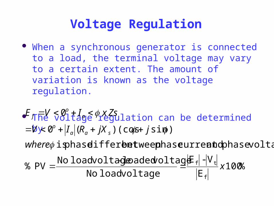
Voltage Regulation
When a synchronous generator is connected to a load, the terminal voltage may vary to a certain extent. The amount of variation is known as the voltage regulation.
The voltage regulation can be determined by
%100 E
V-E
voltageload No
voltageloaded - voltageload NoPV %
voltagephase andcurrent phasebetween different phase is
)sin)(cos(0
0
f
tf x
where
jjXRIV
ZsxIVE
saao
ao
f

Based on phasor diagram, at lagging power factor, the voltage Ef also can be calculated as
Based on phasor diagram also, at leading power factor, the voltage Ef also can be calculated as
22 sincos saaaf XIVRIVE
22 sincos saaaf XIVRIVE
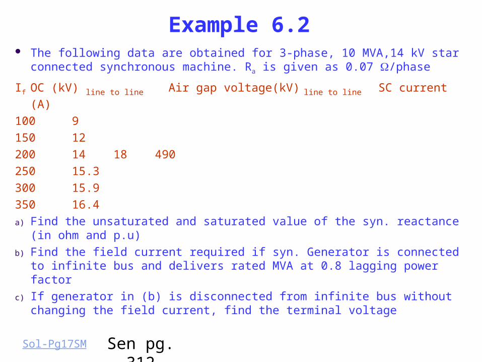
Example 6.2 The following data are obtained for 3-phase, 10 MVA,14 kV star
connected synchronous machine. Ra is given as 0.07 /phase
If OC (kV) line to line Air gap voltage(kV) line to line SC current (A)
100 9
150 12
200 14 18 490
250 15.3
300 15.9
350 16.4
a) Find the unsaturated and saturated value of the syn. reactance (in ohm and p.u)
b) Find the field current required if syn. Generator is connected to infinite bus and delivers rated MVA at 0.8 lagging power factor
c) If generator in (b) is disconnected from infinite bus without changing the field current, find the terminal voltage
Sen pg. 312Sol-Pg17SM

Power and Torque Characteristics
A synchronous machine is normally connected to a fixed-voltage bus and operates at constant speed.
There is a limit on the power a synchronous generator can deliver to the infinite bus and on the torque can be applied to the synchronous motor without losing synchronism.
Analytical expressions for the steady-state power transfer between the machine and the constant-voltage bus or the torque developed by the machine will be derived.

Power and Torque
Per phase equivalent
circuit
Complex phasor
diagram
Complex power S

Power and Torque
(VA)
(Watt)
(VAr)

Power and Torque
Zs=Xs, s = 90o
Power angle / torque angle
•Both power and torque vary sinusoidal with power angle, •Machine can be loaded gradually up to Pmax (static stability limit)•Beyond 90 degree, machine loss synchronism•Field current (Ef) need to be increase if the machine loss synchronism

Example
A 3, 5 kVA, 208 V, 4-pole, 60Hz star connected synchronous generator has negligible stator winding resistance and a synchronous reactance of 8 ohms/phase at rated terminal voltage.
a) Determine the excitation voltage and power angle when machine delivers rated kVA at 0.8 lagging PF. Draw the phasor diagram
b) If the field current is increased by 20% (fixed prime Mover), find the stator current, power factor, and reactive kVA supplied by the machine.
c) With field current as in (a), the prime mover is slowly increased. What is steady state stability limit ?
Sen 319Sol_pg22_SM

Example 1
The synchronous machine in example 6.3 is operated as a synchronous motor from the 3, 208 V, 60Hz power supply. The field excitation is adjusted so that the power factor is unity when the machine draws 3 kW from the supply.
a. Find the excitation voltage and the power angle. Draw the phasor diagram for this condition.
b. If the field excitation is held constant and the shaft load is slowly increased, determine the maximum power & torque that the motor can deliver.
Ans: 137.35< -29o V, 6185 W, 32.8 NmSen pg. 322

The Effect of Changing Excitation Current at Constant Power Output When connected to
infinite bus bar Generator output power (W) control by the amount of steam applied. Pe = VIcos , i.e. Pe proportional to Icos (fixed) Assume the generator operates in lagging power factor
fixed**Remarks: Reactive Power delivered by the generator can be
controlled by the excitation/field current, in over excitation machine supplies inductive reactive power**
Under excited = If small
Over excited = If big
Ia = Iacos + jIasin
vt
Ia1jXs
Ef1
Ia1
Constant power output
Ef2
Limit of instability
changed
Over-excited (lagging p f)under-excited
Power factor = unity (1)
Ia2
Ia3
Ef3
Excitation voltage(E) slides on the constant
power line

The Effect of Changing Excitation Current at Constant Power Output When connected to
infinite bus bar Example :
The star-connected synchronous machine has synchronous reactance of 20 ohm/phase. It supplies load current of 150 A with power factor 0.8 lagging to an infinite bus bar. The bus bar voltage is 11 kV. If the supply steam to the machine prime mover is fixed, calculate the percentage change in excitation voltage if the load power factor load is 0.8 leading. Neglect power losses.
Ans: Eo1 = 8497 < 16.41o, Eo2 = 5145<21.8o; -39%

The effect of Changes the Output Power on Infinite Bus Bar at Fixed Excitation Current
**Remarks: Active Power delivered by the generator can be controlled by the steam supplied into prime mover**
vt
Ia1jXs
Ef1
1
Ia1
Constant power lines
power output varies,
P Iacos
Ef2
Ef3
|Ef1|=|Ef2|=|Ef3|
Ia2jXs
Ia3jXs
Limit of stability of Pmax
2
Ia = Iacos + jIasin
fixedchanged
Unity pf line
Excitation voltage(E)
swings from one the constant power line to
another

Example 2 A 3, 250 hp, 2300 V, 60Hz, Y-connected non-salient rotor
synchronous motor has a synchronous reactance of 11 per phase. When it draws 165.8 kW the power angle is 15 electrical degrees. Neglect ohmic losses. Determine:a. The excitation voltage per phase.b. The supply line current.c. The supply power factor. (0.77 leading)
d. If the mechanical load is thrown off and all losses become negligible,
a. Determine the new line current and supply power factor.
a. Draw the phasor diagram for the condition in (i).b. By what percent should the field current If be changed to
minimize the line current? (75 %)
V151769 o A8.3914.54
0pf;A901.40A901.40 oo
Page 371, Q: 6.2

Complex Power Locus/ Capability Curve
•Define the bounds within which generator can work safely
1. MVA loading < gen. rating (-- stator/armature heating)2.MW-loading < turbine rating (MVA x power factor)
3.Save from steady state stability limit ( < 90 o) 4. Max. field current < specified by rotor heating
Neglect Ra, multiply each phasor by Vt/Xs
XsIacos
vt
IajXs
Ef
Ia
0’ 0 XsIasin
M
N
VtIasin
VtIa
0’ 0
M
Q
s
t
X
V 2
s
ft
X
EV
VtIacos
P

0’

Power Factor Control
An outstanding feature of the synchronous machine is that the power factor of the machine can be controlled by the field current.
The field current can be adjusted to make the stator (or line) current lagging or leading as desired.
The power factor characteristic can be explained by drawing phasor diagrams of machine voltages and currents.

Power Factor Control
Utilize field current to stator current leading or lagging
Leading pf
Lagging pf Over-excitedUnder-excited
Unity p factor
Vt=Ef + jIaXs
Ef =Vt - jIaXs
Normal -excited
Power Factor Control
The unique feature of power factor control by the field current can be utilized to improve the power factor of a plant.
In a plant most of the motors are normally induction motors, which draw power at lagging power factors.
Synchronous motors can be installed for some drives in the plant and made to operate in an overexcited mode so that these motors operate at leading power factors.
This will compensate the lagging power factor of the induction motors and thereby improving the overall power factor of the plant.
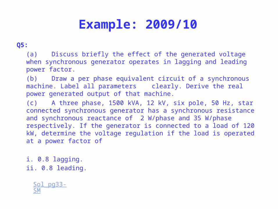
Example: 2009/10
Q5:
(a) Discuss briefly the effect of the generated voltage when synchronous generator operates in lagging and leading power factor.
(b) Draw a per phase equivalent circuit of a synchronous machine. Label all parameters clearly. Derive the real power generated output of that machine.
(c) A three phase, 1500 kVA, 12 kV, six pole, 50 Hz, star connected synchronous generator has a synchronous resistance and synchronous reactance of 2 W/phase and 35 W/phase respectively. If the generator is connected to a load of 120 kW, determine the voltage regulation if the load is operated at a power factor of
i. 0.8 lagging. ii. 0.8 leading.
Sol_pg33-SM

Example 07/08-2
Sol-pg34
![6. СОВЕТУВАЊЕ · [3] M. R. Popnikolova, M. Cundev, L.Petkovska, “Nonlinear Electromagnetic Field Calculation in Solid Salient Poles synchronous Motor”, Proc. Of EPNC](https://static.documents.pub/doc/80x56/5f2cf8f969a71e25b05d3706/6-3-m-r-popnikolova-m-cundev-lpetkovska-aoenonlinear.jpg)


