

THE 8085 MPU &
EXAMPLE OF AN 8085
BASED COMPUTER
LECTURE 7
Dronacharya Group of Institutions

8085 MPU
2
3
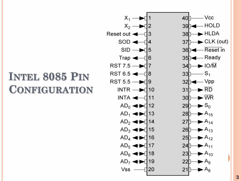
INTEL 8085 PIN
CONFIGURATION

4
Signals and I/O Pins

5
INTEL 8085 CPU BLOCK DIAGRAM

THE 8085 AND ITS BUSES
The 8085 is an 8-bit general purpose microprocessor that can address 64K Byte of memory.
It has 40 pins and uses +5V for power. It can run at a maximum frequency of 3 MHz.
The pins on the chip can be grouped into 6 groups:
Address Bus.
Data Bus.
Control and Status Signals.
Power supply and frequency.
Externally Initiated Signals.
Serial I/O ports.

THE ADDRESS AND DATA BUS
SYSTEMS The address bus has 8 signal lines A8 – A15 which are
unidirectional.
The other 8 address bits are multiplexed (time shared) with
the 8 data bits.
So, the bits AD0 – AD7 are bi-directional and serve as A0 – A7
and D0 – D7 at the same time.
During the execution of the instruction, these lines
carry the address bits during the early part, then
during the late parts of the execution, they carry the 8
data bits.
In order to separate the address from the data, we can use a latch
to save the value before the function of the bits changes.

THE CONTROL AND STATUS
SIGNALS There are 4 main control and status signals. These are:
ALE: Address Latch Enable. This signal is a pulse that become 1 when the AD0 – AD7 lines have an address on them. It becomes 0 after that. This signal can be used to enable a latch to save the address bits from the AD lines.
RD: Read. Active low.
WR: Write. Active low.
IO/M: This signal specifies whether the operation is a memory operation (IO/M=0) or an I/O operation (IO/M=1).
S1 and S0 : Status signals to specify the kind of operation being performed. Usually not used in small systems.

THE FLAGS REGISTER
There is also a flag register whose bits are affected by the arithmetic & logic operations.
S-sign flag
The sign flag is set if bit D7 of the accumulator is set
after an arithmetic or logic operation.
Z-zero flag
Set if the result of the ALU operation is 0. Otherwise
is reset. This flag is affected by operations on the
accumulator as well as other registers. (DCR B).
10
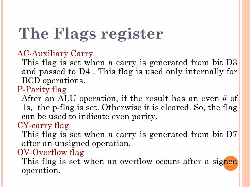
AC-Auxiliary Carry This flag is set when a carry is generated from bit D3 and passed to D4 . This flag is used only internally for BCD operations.
P-Parity flag After an ALU operation, if the result has an even # of 1s, the p-flag is set. Otherwise it is cleared. So, the flag can be used to indicate even parity.
CY-carry flag This flag is set when a carry is generated from bit D7 after an unsigned operation.
OV-Overflow flag This flag is set when an overflow occurs after a signed operation.
The Flags register
MORE ON THE 8085 MACHINE
CYCLES
The 8085 executes several types of instructions with each requiring a different number of operations of different types. However, the operations can be grouped into a small set.
The three main types are:
Memory Read and Write.
I/O Read and Write.
Request Acknowledge.
These can be further divided into various smaller operations (machine cycles).

OPCODE FETCH MACHINE CYCLE
The first step of executing any instruction is the Opcode fetch cycle.
In this cycle, the microprocessor brings in the instruction’s Opcode from memory.
To differentiate this machine cycle from the very similar “memory read” cycle, the control & status signals are set as follows:
IO/M=0, s0 and s1 are both 1.
This machine cycle has four T-states.
The 8085 uses the first 3 T-states to fetch the opcode.
T4 is used to decode and execute it.
It is also possible for an instruction to have 6 T-states in an opcode fetch machine cycle.

MEMORY READ MACHINE CYCLE
The memory read machine cycle is exactly the same as
the opcode fetch except:
It only has 3 T-states
The s0 signal is set to 0 instead.
THE MEMORY READ MACHINE CYCLE
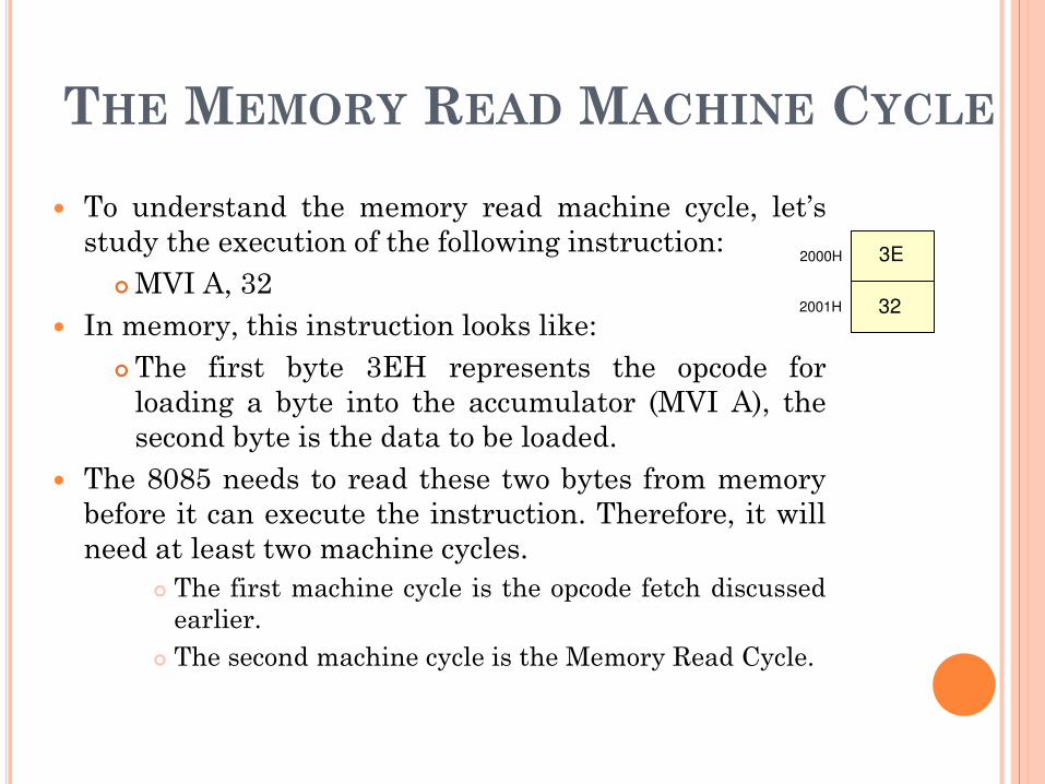
To understand the memory read machine cycle, let’s
study the execution of the following instruction:
MVI A, 32
In memory, this instruction looks like:
The first byte 3EH represents the opcode for
loading a byte into the accumulator (MVI A), the
second byte is the data to be loaded.
The 8085 needs to read these two bytes from memory
before it can execute the instruction. Therefore, it will
need at least two machine cycles.
The first machine cycle is the opcode fetch discussed
earlier.
The second machine cycle is the Memory Read Cycle.
2000H
2001H
3E
32

15
Example of an 8085 based computer

16
System includes interfacing devices such as buffers,
decoders, and latches.
8085 MPU module includes devices such as 8085
microprocessor, an octal latch, and logic gates.
Three machine cycles:
Opcode fetch
Memory read machine cycle
Memory write cycle
Microprocessor external communication can be divided
into three categories:
Memory read and write
I/O read and write
Request acknowledge
Example of an 8085 based computer


