

THE INTERNATIONAL ARAB CONFERENCE ON INFORMATION TECHNOLOGY (ACIT2014)
University of Nizwa, Oman December 9-11, 2014 Page 84
Noise Removal Techniques For Arabic Handwriting
Roqyiah M.Abdeen Ahmed Z.Afifi Ashraf B.Elsisi
Computer Science dept., Faculty of Computers and Information, Menofia University, Egypt
[email protected] [email protected] [email protected]
Abstract: Noise reduction is a very important task for character recognition system. Image quality and execution time are
also important factors to choose the suitable noise reduction approach. Therefore, in this paper a comparative study of six
different noise reduction approaches for Arabic handwriting is presented. These Approaches are mean filter, median filter,
majority morphological filter, majority logic filter, coordinate morphological filter and coordinate logic filter. These filters
are tested on 30 gray scale image of Arabic words with two different noise types (salt & pepper and Gaussian noise) and three
levels of noise density. Mean Square Errors (MSE) and Peak-Signal to Noise Ratio (PSNR) are used to evaluate the image
quality of different approaches. The experimental results show that the morphological filter preserves the details of the image
and gives high PSNR value and low error rate; however, it requires more execution time. The logical filter on the other hand
requires less execution time; however, it gives low PSNR value. The coordinate morphological filter is half way between other
filters, it does not require a high execution time like morphological filter and the PSNR is not low as the logical filter. The
previous filters are tested also on three standard natural gray scale images and the results appear similar with the previous
results for images that contain Arabic handwritings.
Keywords: Noise reduction, Morphological filters, Logic filters,Mean Square Errors, Peak-Signal to Noise Ratio..
1. Introduction
Noise removal is an important topic used extensively in
the field of handwritten or machine-printed documents
analysis. For handwritten documents, the removal of
noise requires careful processing because some types of
noise look similar to certain characters or parts of
characters. Therefore, the noise removal technique may
remove an important feature from the character which
leads to a wrong classification result. Digital capture of
images can introduce noise from scanning devices and
transmission media. Prior to the character recognition,
it is necessary to eliminate these imperfections [9, 4].
When working with handwritten images, the noise can
divide to; low-level and high-level. Low-level noise is
produced by the hardware equipment during the
scanning process; it is a random variation of intensity in
document images. High-level noise refers to
undesirable parts of the image data for the intended
application, and as such they can be inherent parts of
the input data or artefacts that are produced by the
involved hardware equipment or the processing system
[4]. There are many common filtering methods for
noise removal such as the mean and median filters;
however, each one of these filters used to remove
certain types of noise. The median filter can be used to
suppress impulsive noise component while preserving
sharp edges; however, it often fails to provide sufficient
smoothing of non-impulsive noise component. The
mean filter smooth out the edges; but the impulsive
noise components cannot be suppressed sufficiently
[12]. In [13], an improved median filtering algorithm is
proposed. This algorithm uses the correlation of the
image to process the features of the filtering mask over
the image. It can resize the mask adaptively according
to noise levels of the mask. Generally, median filters
or nonlinear filters have been used for noise
reduction but these methods will destroy the natural
texture and important details in the image like the
edges. In [10], an efficient method for impulse
noise reduction from images using fuzzy cellular
automata has been proposed in two stages. In the
first stage, noisy pixels are detected by cellular
automata based on the statistical information. In the
second stage, this information is utilized to change
the noisy pixel by using the fuzzy cellular automata.
In addition to the importance of the image quality, the
fast execution time is required. The work in [11]
present a noise reduction method using Coordinate
Logic (CL) filters applied to printed text and
handwriting images. CL is a family of non-linear
filters, which are very fast in their hardware
implementation [11]. In this paper, a comparative
study between six filters for Arabic handwriting is
provided. These filters are mean filter, median filter,
majority morphological filter, majority logic filter,
coordinate morphological filter and coordinate logic
filter [1-3].
The rest of the paper is organized as following. In
Section 2, the image noise is defined. In Section 3, the
common filtering approaches used for noise reduction
is presented. In Section 4, the Coordinate logic filters
is presented. The experimental results and analysis are
discussed in Section 5. Finally, the conclusion and
future work is put forward in Section 6.
2. Image Noise Noise is an error occurs during the image acquisition
process that results in pixel values that do not reflect
the true intensities of the real scene [6]. Noise
removal algorithm is the process of removing or
reducing the noise from the image. Different
factors may be responsible for introduction of noise in
the image. Noise usually quantified by the percentage
of pixels which are corrupted. The main sources of
THE INTERNATIONAL ARAB CONFERENCE ON INFORMATION TECHNOLOGY (ACIT2014)
University of Nizwa, Oman December 9-11, 2014 Page 85
noise in the digital image are; The environmental
conditions may be affect the imaging sensor during
image acquisition, insufficient light levels and sensor
temperature may introduce the noise in the image,
electronic transmission of image data can make noise,
and if dust particles are present on the scanner screen,
they can also introduce noise in the image [5]. In
document images, there are two types of degradation:
The first one is physical degradation of the hardcopy
documents creation or storage and the second one is
degradation introduced by digitization. If any type of
them is severe enough, the performance of a document
analysis system can be reduced significantly [11].
There are two main differences between handwriting
and machine printed texts; the first difference is that the
handwriting in a document often indicates corrections,
additions, or other supplemental information that
should be treated differently from the main content and
the second difference is that the segmentation and
recognition techniques are significantly different for
machine printed and handwriting texts [15]. Image
noise can be classified to Impulse noise (Salt-and-
pepper noise), Amplifier noise (Gaussian noise),
Poisson Noise (Shot noise) , Uniform Noise
(quantization noise), and Speckle Noise (Multiplicative
Noise) [5].
Impulse Noise (Salt and Pepper Noise) contains
random occurrences of both black and white intensity
values [7]. An image containing salt-and-pepper noise
will have dark pixels in bright regions and bright pixels
in dark regions [8]. This type of noise can be caused by
dead pixels, analog-to-digital converter errors, and bit
errors in transmission.
Amplifier Noise (Gaussian noise) is also called the
normal noise is randomly occurs as white intensity
values [7]. Amplifier noise is a major part of the "read
noise" of an image sensor, that is, of the constant noise
level in dark areas of the image [8], Gaussian
distribution noise can be expressed by:
( )
( √ )
( )
( )
where, x is the grey level image, P(x) is the Gaussian
distribution noise in image x, µ the mean value and σ is
the standard deviation .
Poisson Noise (shot Noise) or Photon noise is a type
of electronic noise that occurs when the finite
number of particles that carry energy, such as
electrons in an electronic circuit or photons in an
optical device, is small enough to give rise to
detectable statistical fluctuations in a measurement.
Speckle Noise (Multiplicative Noise) can be modelled
by random value multiplications with pixel values of
the image [5].
3. Common Filtering Approaches For Noise
Reduction
Image filtering (de-noising) is very important task
in image processing for the analysis of images.
While numerous image filtering algorithms are
available, the best one must delete the largest
amount of noise while maintaining the contents and
details of the image. Filtering methods can be
classified to linear as well as non-linear. The linear
methods are fast enough, but they do not preserve the
details of the images, whereas the non-linear methods
preserve the details of the images [5].
3.1 Linear Filters Linear filter is used to remove certain types of noise.
A mean filter is an example of linear filter. The Mean
Filter (MF) is a simple linear filter, intuitive and easy
to implement method of smoothing images, i.e.
reducing the amount of intensity variation between
one pixel and the next. The idea of the mean filter is to
replace each pixel value in an image with the mean
value of its neighbours, including itself. This works to
delete some of the pixel values that represent
important information in the image, such as edges,
which are not identical with the values of
neighbouring pixels. Mean filtering depends on what
is usually called a convolution filter. Like other
convolutions it is based around a kernel, which
represents the shape and size of the neighbourhood to
be sampled when calculating the mean [7]. Often a
3×3 square kernel is used, although larger kernels (e.g.
5×5 squares) can be used for more severe smoothing.
(Note that a small kernel can be applied more than
once in order to produce a similar but not identical
effect as a single pass with a large kernel.)
There are two main problems with mean filtering:
If there is a pixel value with a very
unrepresentative value, it can significantly affect
the mean value of all the pixels in its
neighbourhood.
When the filter kernel reaches to an edge, the filter
will produce new values for pixels on the edge
and then will blur that edge. This may be a
problem if sharp edges are required in the output
image.
3.2 Non-Linear Filters Nonlinear filters behaviour is slightly different from
the linear filters. For nonlinear filters, the filter can
preserve edges, it is very effective at removing
impulsive noise, but it can be difficult to design.
Median filter (MDF) is a non-linear filter based on the
ranking of pixel values contained in the filter region.
Median filter is good for reducing certain types of
noise such as the salt and pepper noise. A major
advantage of this filter is that it can delete the values
of noise while preserving the important parts in the
image, such as edges [5]. Like the mean filter, the
median filter finding new considered pixel based on
the values of its neighbours but instead of simply
replacing the pixel value with the mean of
neighbouring pixel values, it replaces it with the

THE INTERNATIONAL ARAB CONFERENCE ON INFORMATION TECHNOLOGY (ACIT2014)
University of Nizwa, Oman December 9-11, 2014 Page 86
median of those values. The median is calculated by
first sorting all the pixel values from the surrounding
neighbourhood into numerical order and then replacing
the pixel being considered with the middle pixel value
and if the neighbourhood contains an even number of
pixels, the average of the two middle pixel values is
used.
The median filter has two main advantages over the
mean filter; The median is a more robust average than
the mean and so the pixel of the anomalous value from
the surrounding neighbours, whether it is too large or
too small, cannot affect the median value. Since the
median does not create new unrealistic pixel values, it
must actually be the value of one of the pixels in the
neighbourhood, for this reason the median filter is
much better at preserving sharp edges than the mean
filter.
One of the major problems with the median filter is that
it is relatively expensive and complex to compute. To
find the median it is necessary to sort all the values in
the neighbourhood into numerical order and this is
relatively slow.
4. Coordinate Logic Filters
Coordinate logic filters (CL) is a family of non-linear
filters, which are very fast in their hardware
implementation [11]. This filter depends on the direct
execution of logical operations (AND, OR) between the
binary values of the pixels in the image, which is
similar to the execution of (MIN, MAX) in the
morphological filters. That makes the CL filters to have
analogous functionality with the corresponding
morphological ones, but not the same [11].
CL Filters and their associated Coordinate Logic
Operations (CLOs) are used in many areas related to
image processing like noise removing, edge detection,
opening, closing, skeletonization, feature extraction,
and fractal modelling. CL filters are related to
morphological filters but constitute a separate class of
nonlinear filters. The difference between the
morphological filters and CL filters is that the
morphological filters may be considered as a class of
rank order filters, which involve some kind of sorting,
while the CL filters do not. The CL filters can execute
easily and fast the four basic morphological operations
(erosion, dilation, opening and closing). Therefore, the
filters are expected to be suitable for all the variety of
tasks that are executed by morphological filters [11, 3,
14].
Using coordinate logic operations in combination with
Boolean algebra, powerful filters for noise cleaning can
built [1]. In what follows the majority coordinate logic
(MCL) filter is presented. In the regular majority
function, the output of the function will be the pixel
value that has the majority in this neighbourhood. The
majority CL filter results by checking all the possible
combinations of k objects, taken (k + 1)/2 each time.
Thus the majority CL (MCL) filter implements quickly
and easily an approximation of the measure of the
majority value that is suitable for additive noise
removal [1,3]. In case an active neighbourhood of 5
pixels. One characteristic rhombus structuring element
is described by:
where [*] denotes the location of the origin (i, j)
and * denote the pixels in the structuring element.
The filter structure of a 2D CL filter, corresponding to
this rhombus structuring element, is:
f(i, j) =g(i-1,j)o g(i, j-1) o g(i, j)o g(i+1, j)o g(i, j+1) (2)
where(i ,j) is the location of the original pixel for the
raw i and column j, f(i, j) is the new output pixel in the
filtered image f after applying the majority CL filter
on the original gray scale image g . The specific
majority CL filter results by checking all the
possible combinations of 6 objects, taken 3 each
time, as follows:
( ) [ ( ) ( ) ( )] [ ( ) ( ) ( )] [ ( ) ( ) ( )] [ ( ) ( ) ( )]
[ ( ) ( ) ( )] [ ( ) ( ) ( )] [ ( ) ( ) ( )] [ ( ) ( ) ( )] [ ( ) ( ) ( )] ( )
where CAND and COR is the logical AND, OR
executed among the corresponding binary bits of
equal length of the considered pixels, without
counting the carry bits [3].
The Majority Morphological filter (MMF) is also
implemented using the morphological MIN and MAX
operations. Depend on the Theorem in [14]. Let there
be A, B with A < B. Then
E = A CAND B = min(A, B) = A
D = A COR B = max (A, B) = B (4)
Thus, the majority function can implemented by
replacing the CAND by the MIN operation and the
COR by the MAX operation. The difference between
these two functions is that to enables the CL filters to
behave exactly as the morphological ones it needs to
quantizing the image pixel intensity in usually fewer
gray scale levels than the original image.
Consequently, the new image intensities taking only
the specific decimal values defined bellow. The exact
number of the new allowed levels depends on the
image application at hand and on the available word
length for data representation.
The set of specially quantized decimal numbers is
given by:
{ } ( )

THE INTERNATIONAL ARAB CONFERENCE ON INFORMATION TECHNOLOGY (ACIT2014)
University of Nizwa, Oman December 9-11, 2014 Page 87
In this way the cardinality | | of set equals n+1. If
one uses n-bit words to store decimal numbers, then
she/he can store only n+1 such specially quantized
numbers.
Let , , , .... , i.e. they are numbers
equal to one of the values 0, 1, 3, 7,.... , , where n
is the length of the binary word. Then for the binary
representations of it holds that
E = CAND ... CAND = min
{ (6)
D= COR ... COR = max
{ ( )
where CAND and COR are the coordinate logic AND,
and OR operations between the binary representation of
the pixel decimal values of the image. Since CAND and
COR operators, when operating on numbers belonging
to are identical to the MIN and MAX operators,
respectively [14].
Another Coordinate logic (CL) filters is presented
in[11] perform a combination of erosion and dilation
operation using logical operations, first if we consider
an image I with M×N pixels which M and N are the
numbers of image rows and columns, respectively,
matrix elements of image I well defined as below:
( ) ∑ ( ( ))
( )
Where S(i,j) is the decimal values of matrix elements of
image I. Sp(i,j), p=0,1,...,n-1 are the binary components
of the decimal pixel values. S(i,j), i = 1,2,...,M; j =
1,2,…,N and n is the bits number of binary S(i,j). The
first step for noise reduction, according to equation ( )
the image I has been defined as a matrix, which consist
of binary elements of the original image (decimal
matrix elements of image I must be converted to binary
elements). Since binary conversion affects all matrix
elements, image noise pixels have been also converted
under this conversion. Now, the noise will be separated
using erosion operation as follows:
( ) ∑ ( ( ))
( )
Where Erosion (Sp(i,j)) is the erosion of matrix
elements of image I. The erosion operation on an image
is equal to the coordinate logic AND operator. Equation
(10) can be considered as the coordinate logic AND
operation on all matrix elements of original image
based on the rhombus structuring element and the filter
structure of equation (3). Using this filter structure,
the erosion of the image I using CL filters is given
by :
(i, j) = I(i - 1, j) CAND I (i, j - 1) CAND I
(i, j) CAND I (i + 1, j) CAND I (i, j +1). (10)
The CL-based erosion tends to remove small objects
and small projections, whereas dilation tends to fill
holes and concavities in objects. A dilation
followed by an erosion tends to fill holes and
concavities without change the overall size of an
object [1].
Thus, the next step after noise separation using the
erosion operation is the dilation, the image will be
dilated to fill the holes which is leaved by the erosion
step. is Dilation matrix of Sp(i,j) which is expressed
as:
( ) ∑ ( ( ))
( )
The dilation operation on an image is equal to the
coordinate logic OR operator , Using the rhombus
structuring element, the dilation of the image I
using CL filters is given by :
(i, j) = I (i - 1, j) COR I(i, j - 1) COR
I(i, j) COR I(i+1,j) COR I(i,j+1). (12)
Finally, the proposed filter for noise removal is
presented as:
( ) [ ( ) ( ) ( )]
[ ( ) ( ) ( )] ( )
Where and are coordinate logic OR and AND
operators, respectively.
The CLOs of erosion and dilation act on the specific
set described in equation (6) exactly as the MIN and
MAX operators of morphological filtering [14]. The
same steps of the CLF are applied, but the erosion of
image equation will be:
(i, j) = MAX [ I(i - 1, j) , I (i, j - 1) , I (i, j)
, I (i + 1, j) , I (i, j + 1)]. (14)
And the dilation equation is formed as:
(i, j) = MIN [ I (i - 1, j) , I(i, j - 1) , I(i, j) ,
I(i + 1, j) , I(i, j + 1)]. (15)
The final proposed filter equation will be as follows:
( ) ( [ ( ( ) ( ) (
))] [ ( ( ) ( ) (
))] ( )

THE INTERNATIONAL ARAB CONFERENCE ON INFORMATION TECHNOLOGY (ACIT2014)
University of Nizwa, Oman December 9-11, 2014 Page 88
5. Experimental Results and Analysis
Mean Filter (MF), Median Filter (MDF), Majority
Logic Filter (MLF), Majority Morphological Filter
(MMF), Coordinate Logic Filter (CLF) based on
erosion and dilation and Coordinate Morphological
Filter (CMF) based on the morphological erosion and
dilation were implemented using the Math Works
™MATLAB® 2012 software and tested on an Intel
(R) Core(TM) i5 processor with a clock speed of 2.50
GHz and 6 GB main memory with Windows 7
Ultimate operating system. Salt & Pepper noise and
Gaussian noise are used for testing. These noise types
are applied with three different densities (0.02, 0.06
and 0.1) for Salt & Pepper and with mean =0 for the
Gaussian noise. These noises are applied on 30
images contains Arabic handwriting words, then the 6
filters are implemented and used to remove the noise
from these images. The performance of these six
filters is evaluated by three criteria: the PSNR (Peak
Signal to Noise Ratio), MSE (Mean Square Error) and
the execution time . The MSE is calculated using this
formula:
∑∑( ( ) ( ))
( )
Where ( ) represents the original (reference)
image and ( ) represents the distorted (modified)
image and i and j are the pixel position of the M×N
image. The PSNR is evaluated in decibels and is
inversely proportional the Mean Squared Error [2]. It
is given by the equation:
( )
√ ( )
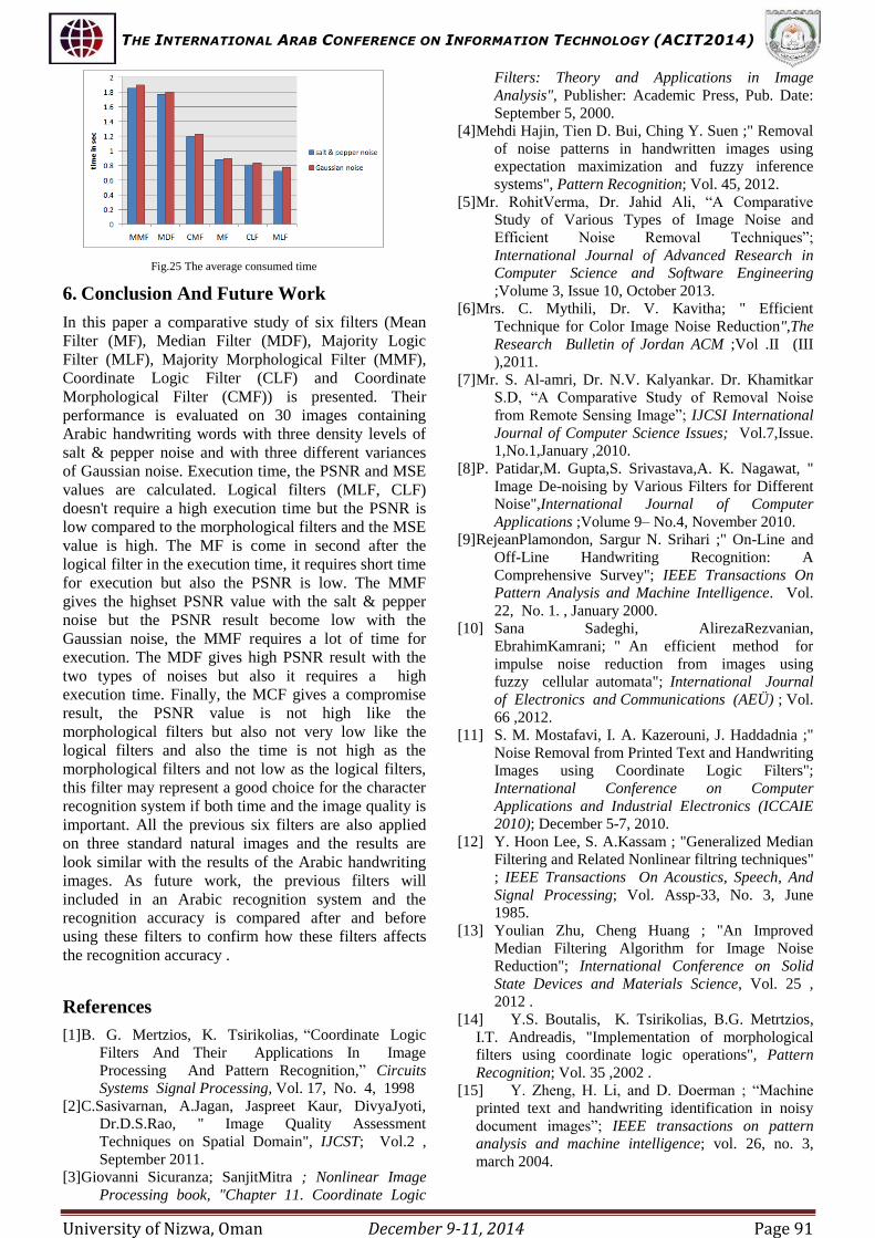
Figure. 1 shows the average execution time in seconds
by the six filters on 30 images corrupted by three
levels of salt & pepper noise. As can be seen from
Figure .1, the filters that depend on the logical
operations (the Majority Logic Filter and Coordinate
Logic Filter) are executed faster than the other filters.
The mean filter is a linear filter it also consumes less
time but it comes after the logical filters, then the
coordinate morphological filter then the median filter
and finally the majority morphological filter. Thus,
the median filter and the Majority Morphological
filter require more execution time than other filters to
remove salt & pepper noise. The same result appears
when applying the Gaussian noise as shown in Figure
2. In Figure 2 also the logical filters consume less
time than other filters then the mean filter and then the
Coordinate Morphological filter, also the Median
filter and the Morphological filter still take more time
than all the other filters.
Fig.1 Average execution time in case of salt & pepper noise.
Accordingly , We conclude that the logical filters is
very fast compared to the other filters and the mean
filter is come after them, the filter that use the
combination of morphological erosion and dilation is
the third one but the median and majority
morphological filters which do more computation
consume more time than the others. But, on the other
hand, when we compare the quality of the image the
result will changed. Figure3 shows the PSNR value
for the sex filters when applying salt & pepper noise
with 3 different levels.
Fig.2 Average execution time in case of Gaussian noise.
As can be noticed in Figure 3, the Majority
Morphological filter which take large execution time
gives the largest PSNR value, the median filter which
come after the MMF in the large execution time is
also gives large PSNR value then the CMF. The
fastest filters (logical filters and mean filter) gives a
small PSNR value compared to all the other filters.
Fig.3 PSNR in case of Salt & Pepper noise.
The Coordinate Morphological Filter (CMF) is in the
half way among others, it does not consume a lot of
time like the MDF and the MMF and the PSNR
value is not small as the logical and mean filters. It is
also do better with the Gaussian noise as shown in
Figure 4. Where the CMF is get the largest PSNR

THE INTERNATIONAL ARAB CONFERENCE ON INFORMATION TECHNOLOGY (ACIT2014)
University of Nizwa, Oman December 9-11, 2014 Page 89
value than the other filter and the MMF is fail with
this type of noise so we conclude that the MMF is
very good only for removing salt & pepper noise. In
Figure 5.a, the original image is corrupted by 0.06
density level of salt & pepper noise. The first two
filters which give a high PSNR value is MMF and
MDF as shown in Figure 5, where Figure 5.b is the
image filtered using the MMF and Fig 5.c is the image
filtered using MDF.
Fig.4 PSNR value in case of Gaussian noise
Now, the third filter which has high PSNR after the
MMF and MDF is the MCF. Figure 6.b shows the
image before and after applying the MCF. Using the
CMF the noise is removed completely but the text is
affected and small changes appeared in the text. The
mean and logical filters are consumed less time than
the other filters but the image is smoothed and some
noise still appears in the text. Figure 6.c shows the
image after using the mean filter. The logical filters
require some quantization process before applying the
filters. Figure 7 shows the quantized image and the
images after removing the noises using the MLF and
CLF. As a result, the Coordinate Filters
(Morphological and Logical) have a good result in the
consumption time and PSNR value with salt & pepper
noise. The second type of noise is the Gaussian noise,
the behavior of many filters will changed because the
Gaussian noise is different from the salt & pepper
noise, the salt & pepper noise just add new white and
black pixels while the Gaussian noise blur the image
and destroy the details of the image more than the salt
& pepper noise. As we can see from Figure 4, the
PSNR value for all filters is slightly closed to each
other; the CMF gives high PSNR value then the
median filter then the MMF and the mean and logical
filters in the last. Fig. 8 show the image corrupted
with Gaussian noise σ=0.06 and the image after
applying the first two filters (CMF and MDF), Fig 9
show the result of the MMF and the MF. Fig 10
shows the result of the two logical filters after
quantizing the image.
(a) (b) (c)
Fig.5 a) Image corrupted with 0.06 density of salt & pepper noise, b) Image
after applying MMF, c) Image after applying MDF.
(a) (b) (c) Fig.6 a) Image corrupted with 0.06 density of salt & pepper noise, b) Image
after applying CMF, c) Image after applying the MF.
(a) (b) (c)
Fig.7 a) Quantized image corrupted with 0.06 density of salt & pepper
noise, b) Image after applying CLF, c) Image after applying the CMF.
(a) (b) (c)
Fig.8 a) Image corrupted with 0.06 density of Gaussian noise, b) Image
after applying CMF, c) Image after applying MDF.
(a) (b) (c)
Fig.9 a) Image corrupted with 0.06 density of Gaussian noise, b) Image
after applying MMF, c) Image after applying MF.
(a) (b) (c) Fig.10 a) Quantized image corrupted with 0.06 density of Gaussian noise,
b) Image after applying MLF, c) Image after applying CLF.
Fig 11 and Fig 12 show the error rate for each filter
using the MSE metric, the error rate is increased when
the PSNR value is small, Thus the error rate is high
with the logical filters and the mean filters while it is
low with the MDF and the MMF and also the CMF is
in the middle .
Fig.11 Average MSE value in case of Salt & Pepper noise.
Fig.12 Average MSE value in case of Gaussian noise.

THE INTERNATIONAL ARAB CONFERENCE ON INFORMATION TECHNOLOGY (ACIT2014)
University of Nizwa, Oman December 9-11, 2014 Page 90
Now the previous filters will tested on three standard
natural images :the Baboon image, the cameraman
image and the pepper image after corrupting them
with 0.02 density of salt & pepper noise and Gaussian
noise then the time ,PSNR and MSE metrics are
calculated and compared with the results of the Arabic
handwriting images. Figure 13 show the original
standard images. The Figures (14-22) shows the
images after applying the six filters, and the Figures
(23-25) show the average time, PSNR and MSE
values. From the previous figures the results appear
very similar with handwritten images results.
(a) (b) (c)
Fig.13 The original images
(a) (b) (c)
Fig.14 a) Image corrupted with 0.02 density of salt & pepper noise, b)image
after applying MMF, c) image after applying the MDF
(a) (b) (c) Fig.15 a) Image corrupted with 0.02 density of salt & pepper noise, b) Image
after applying MMF, c) Image after applying the MDF
(a) (b) (c)
Fig.16 a) Image corrupted with 0.02 density of salt & pepper noise, b) Image
after applying MMF, c) Image after applying the MDF
(a) (b) (c)
Fig.17 a) Pepper image after applying CMF, b) Cameraman image after
applying CMF, c) Baboon image after applying the CMF
(a) (b) (c)
Fig.18 a) Pepper image after applying MF, b) Cameraman image after
applying MF, c) Baboon image after applying the MF
(a) (b) (c) (d)
Fig.19 a) Original quantized image, b) The quantized image corrupted with 0.02 salt & pepper noise , c) The image after applying the CLF d) The
image after applying MLF
Fig.20 Images corrupted with 0.02 density of Gaussian noise.
(a) (b) (c) (d)
Fig.21 a) The cameraman image after applying the MMF b) MDF, c)
CMF, d) MF..
(a) (b) (c) (d)
Fig.22 a) Original quantized image, b)the quantized image corrupted
with 0.02 salt & pepper noise , c) The image after applying the CLF d)
The image after applying MLF
Fig.23 The average PSNR value
Fig.24 The average MSE value
THE INTERNATIONAL ARAB CONFERENCE ON INFORMATION TECHNOLOGY (ACIT2014)
University of Nizwa, Oman December 9-11, 2014 Page 91
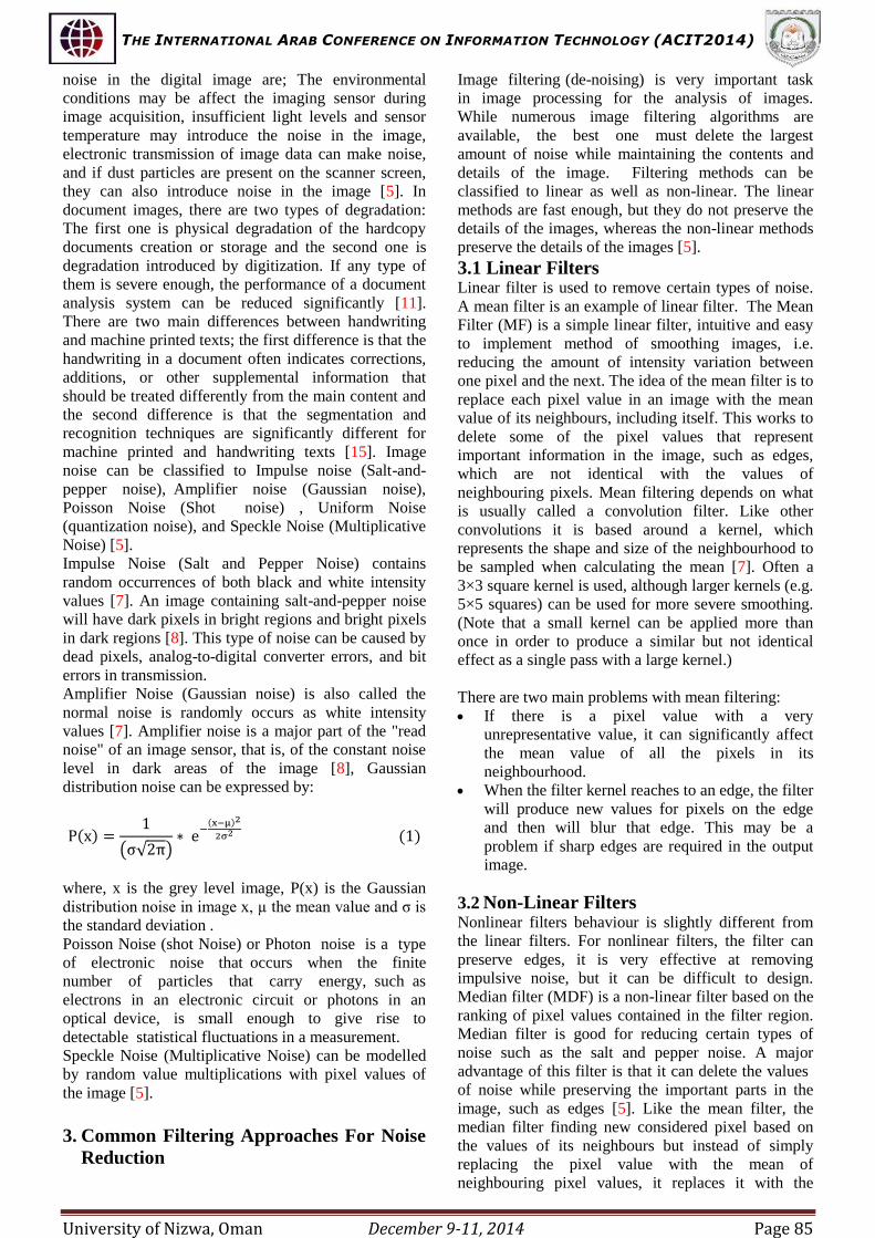
Fig.25 The average consumed time
6. Conclusion And Future Work
In this paper a comparative study of six filters (Mean
Filter (MF), Median Filter (MDF), Majority Logic
Filter (MLF), Majority Morphological Filter (MMF),
Coordinate Logic Filter (CLF) and Coordinate
Morphological Filter (CMF)) is presented. Their
performance is evaluated on 30 images containing
Arabic handwriting words with three density levels of
salt & pepper noise and with three different variances
of Gaussian noise. Execution time, the PSNR and MSE
values are calculated. Logical filters (MLF, CLF)
doesn't require a high execution time but the PSNR is
low compared to the morphological filters and the MSE
value is high. The MF is come in second after the
logical filter in the execution time, it requires short time
for execution but also the PSNR is low. The MMF
gives the highset PSNR value with the salt & pepper
noise but the PSNR result become low with the
Gaussian noise, the MMF requires a lot of time for
execution. The MDF gives high PSNR result with the
two types of noises but also it requires a high
execution time. Finally, the MCF gives a compromise
result, the PSNR value is not high like the
morphological filters but also not very low like the
logical filters and also the time is not high as the
morphological filters and not low as the logical filters,
this filter may represent a good choice for the character
recognition system if both time and the image quality is
important. All the previous six filters are also applied
on three standard natural images and the results are
look similar with the results of the Arabic handwriting
images. As future work, the previous filters will
included in an Arabic recognition system and the
recognition accuracy is compared after and before
using these filters to confirm how these filters affects
the recognition accuracy .
References
[1] B. G. Mertzios, K. Tsirikolias, “Coordinate Logic
Filters And Their Applications In Image
Processing And Pattern Recognition,” Circuits
Systems Signal Processing, Vol. 17, No. 4, 1998
[2] C.Sasivarnan, A.Jagan, Jaspreet Kaur, DivyaJyoti,
Dr.D.S.Rao, " Image Quality Assessment
Techniques on Spatial Domain", IJCST; Vol.2 ,
September 2011.
[3] Giovanni Sicuranza; SanjitMitra ; Nonlinear Image
Processing book, "Chapter 11. Coordinate Logic
Filters: Theory and Applications in Image
Analysis", Publisher: Academic Press, Pub. Date:
September 5, 2000.
[4] Mehdi Hajin, Tien D. Bui, Ching Y. Suen ;" Removal
of noise patterns in handwritten images using
expectation maximization and fuzzy inference
systems", Pattern Recognition; Vol. 45, 2012.
[5] Mr. RohitVerma, Dr. Jahid Ali, “A Comparative
Study of Various Types of Image Noise and
Efficient Noise Removal Techniques”;
International Journal of Advanced Research in Computer Science and Software Engineering
;Volume 3, Issue 10, October 2013.
[6] Mrs. C. Mythili, Dr. V. Kavitha; " Efficient
Technique for Color Image Noise Reduction",The
Research Bulletin of Jordan ACM ;Vol .II (III
),2011.
[7] Mr. S. Al-amri, Dr. N.V. Kalyankar. Dr. Khamitkar
S.D, “A Comparative Study of Removal Noise
from Remote Sensing Image”; IJCSI International
Journal of Computer Science Issues; Vol.7,Issue.
1,No.1,January ,2010.
[8] P. Patidar,M. Gupta,S. Srivastava,A. K. Nagawat, "
Image De-noising by Various Filters for Different
Noise",International Journal of Computer
Applications ;Volume 9– No.4, November 2010.
[9] RejeanPlamondon, Sargur N. Srihari ;" On-Line and
Off-Line Handwriting Recognition: A
Comprehensive Survey"; IEEE Transactions On Pattern Analysis and Machine Intelligence. Vol.
22, No. 1. , January 2000.
[10] Sana Sadeghi, AlirezaRezvanian,
EbrahimKamrani; " An efficient method for
impulse noise reduction from images using
fuzzy cellular automata"; International Journal
of Electronics and Communications (AEÜ) ; Vol.
66 ,2012.
[11] S. M. Mostafavi, I. A. Kazerouni, J. Haddadnia ;"
Noise Removal from Printed Text and Handwriting
Images using Coordinate Logic Filters";
International Conference on Computer
Applications and Industrial Electronics (ICCAIE 2010); December 5-7, 2010.
[12] Y. Hoon Lee, S. A.Kassam ; "Generalized Median
Filtering and Related Nonlinear filtring techniques"
; IEEE Transactions On Acoustics, Speech, And
Signal Processing; Vol. Assp-33, No. 3, June
1985.
[13] Youlian Zhu, Cheng Huang ; "An Improved
Median Filtering Algorithm for Image Noise
Reduction"; International Conference on Solid
State Devices and Materials Science, Vol. 25 ,
2012 .
[14] Y.S. Boutalis, K. Tsirikolias, B.G. Metrtzios,
I.T. Andreadis, "Implementation of morphological
filters using coordinate logic operations", Pattern
Recognition; Vol. 35 ,2002 .
[15] Y. Zheng, H. Li, and D. Doerman ; “Machine
printed text and handwriting identification in noisy
document images”; IEEE transactions on pattern analysis and machine intelligence; vol. 26, no. 3,
march 2004.


