

Netherlands TNO Physics and Electronicsorganization for Laboratoryapplied scientificresearch P'C. Box!J
Oude We;
TNO-report The Hague. The NetherlandsFax +31 70 328 09 61phone +31 70 326 4221
titlereport no. Copy no.
FEL-90-A338 CI9 cvlANDMILITARY SATELLITECOMMUNICATIONSA systems overview and the future developments
AD-A236 441I1111uu11I
Nothing from this issue may be reproducedand/or published by print. phoctosrint.micTohlmi or any other means withoutprevious written consent from TJO.Submitting the report for inspection to author(s):parties directly interesfed is permitted
In case this report was drafted under Ir. J.P. Dezaire- -
instruction, the rights and obligations 3 1of contracting parties are subject to either D I Ithe 'Standard Conditions for ResearchInstructions given to TNO'or the relevant & FLECT[agreement concluded between the contracting
parties on account of the research object date UNO0 7 19911involved. STNO ~February 1991 D
*rID4 K RAPPORTENCEN'rRALEcrederikkazerne, Geb. 140,.,n den B'jrchlaan 31Thiefoon: 070-3166394. 6395 silctnTol ofa X (31) 070-3166202 casfcto
-'tu 90701 tO( ille unclassified2509 LS Den Haag -
abstract unclassified
report teat unclassified
no. of copies 27
no. ofpages 133 (cit. RDP & distribuuti lst)
appendices
AN infortmation which is classified accordtng toDutch regulations shall be treated by the recipient int same way as dlassified information of91-01294 corresponding value in his own country. No part of
11111 1111this information will be disclosed to any party.
__MW 91W Puf T5K 004DhAUMG Wh---w

No .poon
Page2
report no. FEL-90-A338
title CIVIL AND MILITARY SATELLITE COMMUNICATIONS
A systems overview and the future developments
author(s) Ir. J.P. Dezaire Accession 11'o2.
institute TNO Physics and Electronics Laboratory TIS GRA&IDTIC TABUnannouxnced Q
date February 199 1 JuOar con IJust t r i atio n____.
NDRO no. A90KM616 By
no. in pow'90 711 (Communication) 61 D bDIstributiton/Availability Codes
Research supervised by:Ir. l.P. Dezaire Av-- l and/or
Research carried out by:Ir. J.P. Dezaire a Speolal
ABSTRACTI
The project A90KM616, "Orientatie SATCOM", is being performed on behalf of the Royal
Netherlands Navy (RNLN) to assist the Navy on the subject of satellite communications. This
report is the result of the first phase of this study. The goal of the report is to give an overview of
the phenomenon satellite-communication.
The result of the study is a general overview of satellite communications for both civil and
mifiiry applications. Some examples of applications are; international telephony, televisionbroadcasting, small private business networks, and mobile (at the moment still principallymaritime) communications. In these applications satellite communication systems provide aglobal coverage and a high flexibility.
The scientific articles have not been considered because in this stage it was not the intention to
study on a specialist level the broad area of techniques. Magazines, books and a number of reportsof universities and research institutes have been the main sources of information. They provided
afforded an understanding of the existing systems and insight in the future developments.

TNO roprt
Page3
rapport no. FEL-90-A338
titel :CIVIELE EN MILITAIRE SATELLIET.COMMUNICATIE
Een overzicht van de systemen en de Ite verwachten ontwikkelingen
auteur(s) Ir. J.P. Dezaire
instituut :Fysisch en Elektronisch Laboratorium TNO
datum :Februari 1991
hdo-opdr.no. :A90KM616
no. in iwp'90 711 (Communicatie)
Qnderzoek uitgevoerd o.Iv.: Ir. J.P. Dezaire
Onderzoek uitgevoerd door: In. J.P. Dezaire
SAMENVA'ITING
Het project A90KM616, "Orientatie SATCOM', wordt in opdracht van de Koninklijke Marnc
(KM) uitgevoerd om de marine bij te staan op het gebied van satelliet-communicatie. Dit rapport
is het resultaat van de eerste fase van deze studie, waarin het de hedoeling was omn een overzicht
te krijgen van het fenomeen satelliet-communicatie.
Het studieresultaat is een algemeen overzicht van satelliet-communicaie voor zowel civiele als
militaire toepassingen. Voorbeelden van toepassingen zijn; intemnationale telefoonverbindingen
televisie-uitzendingen, Ideine privd-netwerken voor zakeltik verkeer, en mobiele (heden nog vnI.
maritieme) communicatie. In deze toepassingen bieden satelliet-communicatiesystemen een grote
flexibiliteit en communicatie over de hele wereld.
De wetenschappelijkc artikelen zijn buiten beschouwing gelaten onidat het in dit stadium niet de
bedoeling was om op specialistisch niveau het brede scala van gebnaikte technieken Ite bestuderen.
Tijdschriften, boeken en een aantal rapporten van universiteiten en onderzoeksinstituten zijn de
voomaamete bronnen van informatie geweest. Zij gaven inzicht in de bcstaande systemen en de te
verwachten ontwikkelingen.

TNO re wtO
Page4
ABSTRAC'T 2
SAMENVATTING 3
CONTENTS 4
INTRODUCTION 8
2 HISTORY OF SATCOM 9
2.1 SCORE 19
2.2 ECHO 11
2.3 SYNCOM 3 122.4 Experimental satellites 12
2.5 Growth of satellite communications 13
2.6 References 17
3 THE SATELLITE COMMUNICATIONS LINK 183.1 Antenna gain 183.2 Transmitted and received power by an antenna 213.3 Signal to noise ratio and figure of merit 253.3.1 Antenna noise temperature 26
3.3.2 Receiver noise temperature 283.3.3 Figure of merit 283.4 Link budget calculations 29
3.4.1 The uplink equation 303.4.2 The downlink equation 333A.3 Total carrier-to-noise density 343.4.4 Example of a link budget calculation 353.5 Signal processing techniques 373.5.1 Single carrier transmissions 383.5.2 Multiple access techniques 393.5.3 Comparison of multiple access techniques 42

TNO report
Page5
3.6 References 44
4 SATELLITE ORBITS AND FREQUENCY BANDS 46
4.1 Satellite orbits 46
4.2 General overview of frequency bands in use 49
4.3 References 53
5 SYSTEM ELEMENTS IN SATELLITE COMMUNICATION 54
5.1 The Satellite and its communications payload 54
5.1.1 Satellite subsystems 54
5.1.2 The satellite transponder 55
5.1.3 Transponder amplifiers, filters and oscillators 56
5.1.4 Satellite antennas 56
5.2 Earth stations 57
5.2.1 The antenna system 58
5.2.2 The tracking system 60
5.2.3 The receiving system 60
5.2.4 The transmitting system 61
5.3 References 62
6 OVERVIEW OF CIVIL SATELLITE COMMUNICATION SYSTEMq 63
6.1 International systems 636.1.1 Intelsat system 636.1.2 Inmarsat system 67
6.1.3 Intersputnik 69
6.2 Regional and sub-regional satellite systems 69
6.2.1 Eutelsat 69
6.3 Dedicated national domestic systems 70
6.3.1 Canada 70
6.3.2 Luxembourg 73
6.4 References 74

TNO
Page6
7 FUTURE DEVELOPMENTS IN CIVIL SATELLITE COMMUNICATIONS 757.1 Land (and aeronautic) mobile communications 757.1.1 PRODAT 777.1.2 Inmarsat
787.2 Very small aperture terminals (VSATs) 787.2.1 VSAT capabilities 787.2.2 VSAT network topology 807.2.3 The use of VSATs 817.3 New technologies 827.3.1 Spot beam antennas 837.3.2 Satellite-based switching 857.3.3 Intersatellite links 867.3.4 Conclusions
877.4 References
89
8 OVERVIEW OF MILITARY SATELLITE COMMUNICATION SYSTEMS 938.1 United States 938.1.1 IDCSP
938.1.2 TACSAT
938.1.3 DSCS II 938.1.4 FLTSATCOM and AFSATCOM 948.1.5 DSCS 11 ([3], [4], [5]) 978.1.6 TDRSS [61 998.1,7 Navstar/GPS
998.1.8 Ground mobile forces satellite communications 1018.2 NATO
1028.3 United Kingdom ([13],[14],[15]) 1048A USSR
1058.4.1 Molniya [23] 1058.4.2 Stationar [24] 1068.4.3 Other satellites 1068.5 References
107

TNO rpr
Page7
9 THE FUTURE OF MILITARY SATELLITE COMMUNICATIONS 110
9.1 Shortcomings of the current satellite communication system 110
9.2 Future developments 112
9.2.1 Transition to mobile communications with NATO IV 112
9.2.2 Future U.S. military strategy 112
9.2.3 Optical satellite communications 1139.3 Future satellite systems 113
9.3.1 NATO SATCOM Phase IV 1139.2.2 Milstar 114
9.2.3 Lightsat 117
9.3 References 118
10 COMPARISON OF CIVIL AND MILITARY SATCOM SYSTEMS 120
10.1 Threats and countermeasures 120
10.1.1 Nuclear threat 120
10.1.2 lamming 121
10.2 Comparison of the Intelsat V and the DSCS III satellite 123
10.3 References 126
11 CONCLUSIONS 127
12 BIBLIOGRAPHY 129
LIST OF ABBREVIATIONS 130

TNO rponP
Page8
1 INTRODUCTION
The Royal Netherlands Navy (RNLN) is procuring fifteen ship-borne satellite communication
earth stations. These ship-borne terminals will form a satellite communication network together
with a NATO satellite and a large ground station in Schoonhoven, the Netherlands. This system
will improve and complement the long distance communications (mainly provided by HF-
communications) between the ships and the shore (Schoonhoven) and between ships. The
network implementation will introduce network control and management aspects and possible
EMI effects due to the large amount of electronic equipment using electromagnetic waves causing
mutual interference. In addition, the satellite communication (SATCOM) installation must bedesigned to be reliable in rough circumstances and in periods of tension and war.
In order to be able to produce technical solutions to the implementation aspects, the RNLN
committed the Physics and Electronics Laboratory (FEL) with a study on satellite communication
to gain more knowledge about this field of interest. The study consists of two phases. The firstphase is a literature study, of which the main goal is to get an overview of the satellite
communication community, the users and the applications, and future developments. The secondphase consists of the identification of the implementation aspects.
The first phase of the study will be finished by two reports. This report is the first one. It gives a
general overview of the techniques that are employed, the existing communication satellites, the
most well-known civil systems, the military systems, and the future developments in techniques,technologies and applications. A second, confidential, report will follow concerning the military
operational aspects on satellite communications.

TNO report
Page9
2 HISTORY OF SATCOM
Why is satellite communication so important? The two main reasons ar the large coverage area
and the flexibility that it provides [1]. Systems using a single satellite offer the flexibility to
interconnect any pair of users separated by great distances up to approximately one-third of the
circumference of the earth. Systems using three satellites can provide a global coverage with
multiple-access flexibility, including communication links between satellites and fixed points on
earth, ships at sea, airplanes, other moving vehicles, and man-pack terminals. Satellite
communication costs are essentially insensitive to the distances between terminals. Another
strong point of satellites lies in the fact that they can handle a large amount of traffic, although
this benefit is provided by terrestrial microwave links and optical fibre links as well.
The theoretical possibility of placing three satellites in a geostationary orbit was proposed by
Arthur C. Clarke, also known as a science-fiction author, in his article "Extra-terrestrial Relays",
Wireless World, October 1945. After this proposal it lasted for eighteen years before the first
geostationary satellite was placed in orbit. 'he global coverage that three satellites can provide is
shown in Fig. 2.1. Note the "shadow" areas in the polar regions, which can be covered by
satellites in specific orbits as will be discussed in chapter 2.

TNO repot
Page10
WEw
Ii Yr
Fig. 2.1: Global coverage provided by the Inmarsat system [2]
The first space communications activity can be traced back to 1946 when the U.S. Army achieved
radar contact with the moon. In 1954 the U.S. Navy began communications experiments using the
moon as a passive reflector. In this way an operational communication link was established
between Hawaii and Washington D.C. [3] by 1959.
2.1 SCORE
The first man-made communication satellite, Project SCORE, was launched in December 1958.
The primary purpose of the project was to demonstrate that an Atlas missile could be put into
orbit. Demonstration of a communications repeater was the secondary goal. The life time of this
satellite was twelve days of which about eight hours were actual operation, after which the
batteries failed. The SCORE communication subsystem is shown in Fig. 2.2.

TNO p0't
PageI1
Fig. 2.2: SCORE Communication Subsystem [31
Any of the four ground stations in the southern U.S. could command the satellite into a playback
mode to transmit the stored message or into a record mode to receive and store a new message
(Fig. 2.2). A real-time mode was also available in which the recorder was bypassed. One of the
recorded signals was a Christmas message of President Eisenhower.
2.2 ECHO
During the late 1950s and early 1960s, the relative merits of passive and active communication
satellites were often discussed. At the time of Project Echo, the main advantages given for passive
satellites were: very wide bandwidths, multiple access capability, and no chance for degradations
due to failures of satellite ilectonics. The disadvantages were: the lack of signal amplification,
the relatively large orbit perturbations resulting from solar and atmospheric effects (because of the
large surface-to-weight ratio), and the difficulty in maintaining the proper reflector shape. The use
of active satellites soon overshadowed the passive satellites.
Project ECHO produced two passive satellites. Echo I was a sphere with a 100 ft diameter,
whereas echo 2 was even larger with a diameter of 135 ft. They were launched in 1960 and 1964.
Echo I was used for picture, data, and voice transmissions between a number of ground terminals
in the United States and also for radar and optical measurements. Echo 2 was used primarily in
scientific investigations similar to those performed with Echo I and very little for
communications purposs.

TNO reporl
Page12
2.3 SYNCOM 3
After the launch of some other experimental satellites (Courier, West Ford, Telstar and Relay) the
system planners wanted to place a satellite in geostationary orbit. The National Aeronautics and
Space Administration (NASA) conducted experiments at synchronous altitude using the Syncom
satellites. Of these satellites Syncom 3 was the first satellite to be placed in geostationary orbit
[4], which means that the satellite remains above a fixed geographical position on earth. The
channelization consisted of two 500-kHz channels for narrowband two-way communications and
one 5-MHz channel for one-way wideband transmissions. The wide-band channel was used to
transmit the Tokyo Olympic games in the fall of 1964.
2.4 Experimental satellites
Because the private industry cannot support the higher risk, higher potential developments which
require about a decade to bring them to commercial usefulness, there is a continuous need for
government funded experimental satellites. As a result of the development and launch ot these
satellites a lot of progress has been made during the twenty years after the launch of Syncom 3.
For these reasons NASA (US) was able to start their most recent project, developing the
Advanced Communications Technology Satellite (ACTS).
The ACTS program objective is to develop and flight qualify high-risk technologies and
techniques for the next generation of commercial communications satellites (5]. This satellite is
not a simple repeater, but it contains a modem and a baseband processor able to sort, store, and
route messages. ACTS uses the Ka band, 30- GHz uplink and 20-GHz downlink transmission. To
combat fading at Ka-band frequencies, fade-countermeasures like adaptive coding and power
control techniques are used. It interconnects different areas on earth by means of three antenna
spot beams and a 3 x 3 switching matrix. The use of spot beams allows the use of very small
ground stations with antennas of 1.2 to 1.8 metre in diameter.
In this context reference is made to the recent direct broadcasting satellites above Europe, which
allow TV-reception with dishes of only 60 centimetres. This compares with the groundstations of
30 metres that were used for the television broadcasts through the Intelsat-I satellite, launched in
1965, this being the first one commercially used [6]. It is worth mentioning that the Intelsat A
station is still this large because it supports the current international trunk circuits, which carry

TNO rot
Page13
large bandwidth source signals. In the following chapter it will be explained why the transmission
of large bandwidth source signals requires such a targe antenna.
In Europe and Japan programs similar to ACTS are carried out. The European Space Agency
(ESA) has launched succesfully the experimental satellite OLYMPUS in 1989 while the National
Space Development Agency of Japan (NASDA) will launch its largest experimental satellite
(ETS-VI) in mid-1992 [9].
2.5 Growth of satellite communications
A lot of examples could be elaborated here to show the progress of satellite communication
during the last 25 years. However, the reader is invited to compare the satellite systems of this
moment, described in chapter three, with the first geostationary satellite Syncom 3. launched in
1964. But not only the satellite systems themselves have grown in there number, size and
complexity, also a lot of satellite organisations have been founded.
An important organisation is the National Aeronautics and Space Administration (NASA), which
is an Agency of the US Government. It has a significant role in all aspects of space exploration
and research. Its counterpart in Europe is the European Space Agency (ESA). ESA is engaged not
only in space research, but also in the operation of communications and broadcasting satellites.
Intelsat (the International Telecommunications Satellite Organization) is the oldest
communications satellite organisation, existing already for more than 25 years. Fig. 2.3 on the
next page shows the growth of the number of Intelsat groundstations during the years. Inmarsat
(International Maritime Satellite Organisation) is an organisation similar to Intelsat, but
concentrates on communications to ships, offshore oil platforms, and quite recently extended its
area of interest to land and air mobile communications.
Other organisations are the military organisations like the US Department of Defense (DoD) and
the North Atlantic Treaty Organisation (NATO). They support the procurement and development
of their own satellite systems because military satellite systems are to be survivable under threat,
in which they differ from civil systems.
.1 .. .. .

TNO report
Page14
*50 49S
338
• ,'"1', , 1146
,. ,'0" f", .I
Fig. 2.3: Growth of the number of Intelsat ground stationsover the past years [7]
Next to these large organisations, a lot of regional and domestic systems have evolved to meetspecific regional and national demands. To inlustrate the number of communications satellites,Fig. 2.4 and 2.4a 181 on the next two pages arc included. It shows the current occupation of thegeostationary orbit by communications satellites, together with a brief description of them.
"S * W.'S'5SS I ** m m

TNO repot
Page15
c-
C-pi" by S J tA4OtUS
E WE: 60*E:W..V, VWM -P. ~ c T ,oLW .M-1 c WTV Ep t. P1 t,
V~k~mr7.=* W*.VF2~~m m: ,= V f.W.&" ,f ' w P-ya wmw p.6.1 *vM cx 5 wstW
.Vk W McwYf dAlIIG t .w .29:amv h maO
wy S J BJRX ,L
bw~i Ao~- n w TV) us VF2S* 9 M a abs iS W" 0d -'ee Fe wnlAbd- tv, Tk No. N- Fmvftft ~ ISO geiekzamu .
Ptgoi 9uexu1 h bnf kMin %gii £NBe ,A.inpIenbWWi bs'* beu.R iei.PA CCk dwA d
cuc~i.~enyb wd Vii 0* w ente-9.'vd~nir~n.C necP~ T~ens L 2E 1FaNiM S
P9*VF "'0". fti w-999 -e IA~hen~ W.0i.CLCUtow.. Awdpt& A9Lieveath. nb-. IW been
coodi*) stt w ", ownuvq 09IW" 29dvwpee IAL(w i9&ent9b ~uU~in wN'w~AF-= d .ciW efwb iwinen-WoewVwvu
wec9 a9'C' W*p d mv, ~ ~ ,SSeS a ~ ~ )d ue ~ec~so- ~ ft~ paawy T~ce, lobbcwnOe.~ wVLe ~ e~~~
Fig. 2A Ovi sate~tes i gostt sar nfteab

TNO 'epon
Page16
Abuev Wb.. m~~ umdf Am pm LE 1 Z
LirE---d t A kMF V- ,- &-w-vMKJ PbbhVF
Lyt SI E ' *- yI d.
- T~~~.W= lK.~a.* UbI.d S. bj.1J db ra ba ns.pftgcM ET % Nf Ob -E by Uha
1CE: AF-YP S pw b. S) .,1V .. = "As ,MUoq
~a& m ha Tl. ta:a a Ga,. M aGad WA 02 UCU a.datrA kabd VMF4D"b- .c~
131E: I-AN TV Pa. 1. GM
lZalt~~h maw Naa-M W. AMda ~b,.AAJ..,abaa--"dS
c. l.a = =Wl 1,;34.5-W;.g'..~w
gEAA~TaVWi V* . Atfat Lb
Ma.~~baay~Pah FIO-d da.ftvwa...LaaCW y Ewoa mSA d 8lmW-4f.daUjaU.wtyTa
d- aW ft. PA id... ft. SP" ala T=U .bEW&-%U .WTVE. GUT SSICatA- ,S PBSV M .Ft l a , otha.,n
Fag.pv.0~w 2.4a: CninaoNA wfk. 2.

TNO mpW
Page17
2.6 References
[1] Dr. Kamilo Feher, "Digital Communications satellite/earth station engineering",
Copyright by Prentice-Hall Inc., Englewood Cliffs, N.J. 07632 U.S.A., 1983
[2] Olof Lundberg, Director General, Inmarsat, "Inmarsat's potential for the aviation
community", Communications International, november 1983
13] D.H. Martin, "Communication Satellites 1958 to 1986", Programs Group, The Aerospace
Corporation, El Segundo, Calif. 90245, 653 pages, October 1984
[4] Tom Ivall, "SATELLITE SYSTEMS, 25 years of geostationary orbits", Electronics &Wireless World, page 1127, 1988
[5] F. Michael Naderi and William W. Wu, "Advanced Satellite Concepts for Future
Generation VSAT Networks", IEEE Communications Magazine, September 1988
[6] S.J. Campanella, "Perspectief voor toekomstige communicatie-satellieten", Dutch
translation by W.A.M. Snijders, 12-Elektrotechniek/Elektronica No.9, 1988
[7] V.J.M. Vermeulen, "PIT en Satellietcommunicaie", verslag van de CBO -bedrijfsconferentie voor HBO-docenten 1982, Uitgave Dienst Onderwijscontacten,
oktober 1982
[8] S.J. Birkill, "Datafile transponder watch", Cable & Satellite Europe, March 1989
[9] Jim Chalmers, "Japan's satellite challenge", CEI, June 1989

TNO report
Page18
3 THE SATELLITE COMMUNICATIONS LINK
In this chapter the key elements of a point to point satellite communications link will be
discussed. The following three sections will discuss the transmitting and receiving antenna gain,
the power received by an antenna and the signal to noise ratio on a satellite communications link.
These sections will be the basic for the fourth section on linkbudget calculations, which gives the
basic for the engineering of earth stations given a certain satellite. The last section of this chapter
will discuss the signal processing techniques needed to change the original source signal to a
radio frequency signal suited for transmission to and from the satellite.
3.1 Antenna gain
One of the most essential components of communication satellites and earth stations is the
antenna. This antenna often consists of a feed system, which transforms the electriccommunications signals into an electromagnetic wave, and a reflector dish, which directs the
electromagnetic waves on the path between the earth stations and the satellite. This directivity of
the reflector avoids the waste of electromagnetic power, as the path from earth station to thegeostationary communication satellite is approximately 36.000 km and causes a power loss that is
around 200 dB.
The gain of an antenna, which in fact is a measure of the directivity, is defined with respect to the
gain of an isotropic antenna. An isotropic transmitting antenna radiates a spherical wave with a
uniform power po/4x in any direction of the surrounding space (po being the power available at
the input of the antenna). A reflector antenna (Fig.3. 1, next page) will radiate to a receiver a
power which depends on the angle (0) between the straight path from transmitting antenna to the
receiver and the axis of the reflector dish (Fig. 3.2 and 3.3 on the next pages). Fig. 3.2 shows
theoretical pattern and the so called main lobe and side lobes, while Fig. 3.3 shows the actually
measured radiation pattern of a reflector dish antenna as a function of 0.
The antenna gain g (or G if it is expressed in decibels) is maximum on the axis of the dish and
defined as the ratio of the maximum gain and the isotropic gain.
g = PM (1)po/4x

TNO ~pr
Page
19
e.0a
* Aperture* area A
Reflector(Diameter D)
Fig. 3.1: Earth station antenna
mefik~ Main kft
Fig. 3.2: Antenna radiation patien, main lobe and side lobes

TNO epon
Page20
Relothi. gain
Fig. 3.3 Antenna radiation as a function of 0
The maximum gain, often referred to as antenna gain g, is usually expressed in decibels (dBi, i.e.
dB over isotropic, the isotropic gain is 0 dBi). A very important relation between the gain, the
wavelength X (in metres), the antenna efficiency T1, and the projected aperture area A (in square
metres, shown in Fig. 3.1) of the reflector dish is:
gmax =4 A (2)
where X = /, c is the RF waves velocity = 3 x l01 (m/s) and f is the radio frequency (Hz),
If the antera would be perfect and lossless, the antenna efficiency Tj would be equal to 1, but duc
to losses and the non-uniformity of the illumination of the reflector by the feed system practical
values of I are between 0.6 and 0.1. TIA is called the "effective area" of the antenna.
For a circular aperture with diameter D (A = xD2/4) the gain function, expressed in dB, would be
0= 10 log gma = 9.94 + 10 log Ti + 20 log (D[X) dBi. (3)
From the equations above it will be clear that the ant a gain is proportional to the aperture area
of the reflector and the square of the radio frequency. A typical antenna radiation diagram has

TNO rep
Page21
already been depicted in Fig. 3.3, which shows the half power beamwidth Oo and the antenna gain
as function of the angle 0 at a fixed frequency.
3.2 Transmitted and received power by an antenna
If pe (e stands for exciter) is the power that is supplied to the antenna and ge is the antenna gain in
a given direction, then the product pe.ge is called the equivalent isotropically radiated power in
that direction, or e.i.r.p. (often also abbreviated as EIRP). If it is expressed in decibels, the unit is
dBW (Pe in dBW + Ge in dBi). The e.i.r.p. is often one of the important characteristic values in
specifying a satellite or earth station. The power flux-density (pfd), i.e. the power radiated by the
antenna in a given direction at a sufficiently large distance d per unit of surface area, can be
written as a function of the e.i.r.p.:
(pfd) = e.i.r.p./(4zd2) (4)
Combining (2) and (4), the power that is received by an antenna can now be defined as
pr = (pfd)-rA = p2ge-gr(4 ) (5)
where r stands for receiver.
From formula (5) it can be concluded that the received power is determined by the excited power
and the antenna gain at the transmitter, the antenna gain of the receiver, and a term of which the
reciproke represents the fre-space loss between isotropic antennas. This term is defined as
I = (4 A,)2, (6)
or in decibels as
L = 20 log (4adA). (7)
At a frequency of 6 GHz and a distance of 36.000 km this attenuation is 200 dB.

TNO report
Page22
The received power will actually be less than calculated with formula (5), because as well as
losses due to free-space attenuation other losses must be taken into account. Additional losses are:
Losses due to polarization mismatch of the electromagnetic wave at the antenna interface and
to cross-polarization caused by propagation (the electrical component of the incoming
electromagnetic wave will then consist not only of an electrical, but of a magnetic component
as well, and the same applies to the magnetic component the other way round).
Losses due to antenna offset with respect to the nominal direction commonly referred to as
pointing error losses. The degradation to the antenna gain AG as a function of the off-boresight
angle AO is
AG = 12 (A0/0) 2 dB. (8)/
The half power beawidth 0o can be calculated with the following formula:
0o = 65 41D. (9)
Feeder losses, generally included in the e.i.r.p. on emission and in the station sensitivity on
reception.
Atmospheric losses representing the losses due to propagation in the atmosphere and the
ionosphere.
The atmospheric losses need some further explanation here, because they can be very significant.
The actual atmospheric losses are very dependent on the expected rain fall in the communicationarea and the frequency band. For frequencies up to 10 GHz the losses are smaller than one dB. but
at frequencies of e.g. 30 GHz the losses may be several tens of decibels. The influence of rain-
induced atmospheric attenuation as a function of the frequency is depicted in Fig. 3.4 [ ].

TNO tewt
Page23
I0
V 100
to 50
25
12-
I.- 5.0
0.01 10 '00FREOLVcY (GHZI
Fig. 3.4: Rain-induced attenuation
As well as the rain-induced attenuation an extra atmospheric path loss due to atmospheric gasses
has to be accounted for. This attenuation is also frequency dependent and is shown in Fig. 3.5 [ I].
As one can see, this extra path loss is neglectable in respect to that caused by rain fall. At very
high frequencies however (higher than 50 GHz) the attenuation is large and has a specific
maximum at 60 GHz. This can turn to an advantage however for military intersatellite
communications links (see section 7.3.3) at 60 GHz, which cannot be detected or disturbed by an
enemy from earth.

4 TNOrepo.I
Page24
I I- -
I I I
I I
j 'I
11 M
Pressure I! [IITemperatur :00 I-Water vao :7. gII
IIY I3 DU S UI

q
TNO report
Page25
3.3 Signal to noise ratio and figure of merit
The signal to noise ratio is a very important measure, since its value determines the quality of
reception. To obtain the signal to noise ratio, the received signal power and the received noise
power have to be calculated. The received power can already be calculated with the knowledge
obtained from the previous paragraph.
The received noise power is due to an internal noise source in the receiver and to an external
source, the antenna contribution. In satellite communications link budget calculations (see the
following section) usually the term noise power (N expressed in Watts) is not used, but the noise
spectral density in W/Hz (No), or the noise temperature (T in absolute degrees Kelvin). This is to
avoid the need for specifying the bandwidth B in which the noise is measured. The terms are
related as:
N=kTB and No = N/B, so No = kT. (10)
where k is Boltzmann's constant, 1.38 x 10⁻²³ Joule/Kelvin (or -228.6 dB Joule/Kelvin). Now that
the terms have been specified, the noise temperature of a receiving system will be calculated.
TA TR
antenna attenuator receiver
Fig. 3.6: Noise temperature of a receiving system
Fig. 3.6 shows a receiving system, which includes the antenna, the receiver, and the attenuation
between antenna and receiver. The attenuation is caused by losses in the antenna, the feeder or the
space between the signal source and the antenna. The noise temperature of this receiving system
referred to the receiver input is
Ttsac) = Ti + Ta(1 -/a) + Tda (11)

TNO report
Page26
where TRStatm = temperature of the receiving system referred to the receiver input
TR = temperature of the receiver
Ta = temperature of the attenuator
a = loss due to the attenuator
TA = temperature of an antenna, equal to the sum of the external noisecollected by the antenna
If the noise temperature is referred to the output of the antenna, it is equal to
TRS( = TA + (a-l)Ta + a.TR (12)
Usually, in a carefully designed system, the losses are neglectable and "a" almost equals 1. Then
the receiving system noise temperature can be written as
TRS =TA + TR (13)
3.3.1 Antenna noise temperature
The antenna noise temperature will be different for the satellite and the earth station.
The main lobe of a satellite antenna, which receives the main part of the total received power, is
facing the earth (Fig.3.7). The noise from the radio stars, the sun, the moon and the other planets
has a minor noise temperature of 6 K [2] and is only received by the antenna sidelobes. The
terrestrial noise due to atmospheric attenuation and ground is therefore the dominant contribution
to the total noise. The total noise power received by the satellite antenna is determined by the
terrestrial noise which has a noise temperature of about 290 K.

TNO report
Page27
Fig. 3.7: Noise received by satellite antenna
Sky noise
Ground noise
TA =TSky +TG found
Fig. 3.8: Noise received by earth station antenna
An earth station antenna pointing straight upwards to the sky is facing the radio stars, the Sun, the
Moon and the planets, so the received noise power should have a temperature of only 6K (Fig.3.8). However, via the antenna sidelobes a small portion of the large terrestrial noise power will
be received. This portion will be more significant if the elevation angle (the angle of the antenna
disk axis with the ground plane) is less than 90 degrees. This situation wil occur very often,
because many earth stations will not be positioned on the equator. In Europe for example, the
elevation angle is about 30 degrees. Depending on its radiation diagra.m, the antenna will collect
ground noise via its sidelobes. The larger the antenna or frequency, the less noise will be collected
this way because the antenna beamwidth will be smaller (formula (9)). Typical antenna noise

TNO repoat
Page28
temperatures are 10K for a large Cassegrain antenna [3, page 240] and 100 K for a small dish
antenna.
3.3.2 Receiver noise temperature
The noise factor F of a receiving amplifier is given in its specifications and is a figure which is
determined by the receiver noise and a reference temperature To (To = 290 K). The receiver noise
temperature TR can be calculated with the noise factor F of the receiver as follows:
Ti = To.(F-1) (14)
The noise factor is often provided in decibels, so it has first to be calculated in absolute values.
Solid state gallium arsenide field effect transistor (FET) amplifiers with a noise factor of about 1.8
dB (1.51 in absolute values) at 12 GHz are already on the market. This gives the following
receiver noise temperature:
TR = 290 K- (1.51 - 1) = 150 K.
This is a very satisfactorily value when such a receiver is combined with small dish antennas
having an antenna temperature of about 100 K. For the large antennas with a temperature of only
10 K it would be a waste not to use cryogenic parametric low noise amplifiers with a noise
temperature of about 15 K.
3.3.3 Figure of merit
The signal to noise ratio for reception depends on the received signal power and the noise
temperature of the receiving system. This can be calculated with the formulas given in the
previous paragraphs, but this is not always needed because often the transmitted e.i.r.p. and the
figure of merit of the earth stations and the satellite are specified. The figure of merit is defined as
the ratio between the gain of the receiving antenna in the direction of the received signal and the
receiving system noise temperature defined by equation (12).
Gf'=101ogg-10logT s sr dB/K
The e.i.r.p. and figure of merit are key design parameters for transmitting and receiving systemsof earth stations and for transmitting systems of satellites. The noise temperature of satellite

TNO ,epont
Page29
receivers is not that critical, because the antenna noise temperature is always about 290 K and
therefore placing a very low noise amplifier in satellite receiving systems makes no sense.
Typical figures of uerit for earth stations are: 41 dBIK at downlink frequencies of 4 GHz with
earth station antennas of 30 m and a cooled parametric amplifier, 23 dB/K for an antenna of 4.5
meter in diameter and a FET-amplifier. For satellites the figure of merit ranges from -19 dB/K for
an earth coverage antenna to 0 dB/K for a narrow spot beam antenna at uplink frequencies of 6
GHz.
3.4 Link budget calculations
Pertinent to an understanding of the critical aspects of a satellite communication link are the
following link calculations, which will briefly be discussed and illustrated. The space link consists
of the path from the earth station to the satellite, called the uplink, and the path from the satellite
back to the earth station, called the downlink. The concept of a point to point satellite
communications link is illustrated in Fig. 3.9. In this picture the following variables are depicted:
[ I l "- I I i i I
Gsr, Tu pS.G,2
PPO." Ger. Td
Fig. 3.9: Point to point satellite communications link

TNO report
Page30
Pe The transmitted power by the earth station.
Get The antenna transmission gain of the earth station on the left.
Gsr The antenna reception gain of the satellite antenna.
Gst The antenna transmission gain of the satellite antenna.
Ger The antenna reception gain of the earth station on the right.
Lu The free space attenuation in the uplink.
Ld The free space attenuation in the downlink.
In most cases the same antenna is used for transmission and reception. The transmitting and
receiving frequencies are different and can be separated by the use of a diplexer feed in theantenna. The use of different frequencies for transmission and reception, while using the same
antenna, causes a difference in transmission gain and reception gain.
3.4.1 The uplink equation
The uplink equation, which gives an expression for the carrier-to-noise spectral density c/No
(C/No if expressed in decibels) on the path to the satellite, appears in the two forms below,depending on the perspective and available information. Where satellite receiver characteristics
are given, the first one is used; where earth station transmit parameters are given (using the
parameters of Fig. 3.9), the second one is convenient.
(c/No)u = (pfd)u - (X2/4ir) • (gjT)s / (k -. u) (15a)
(c/No)u = (e.i.r.p.)e - (g/r)s / (lp~u -k- Iru) (I5b)
where u designates the uplink
s designates the satellite
(pfd)u = power flux density for the uplink
(g/T)s = figure of merit for satellite
k = Boltzmann's constant (l.380x10 23J/K, or in decibels -228.6 dBW/K.Hz)
Jru = uplink margin for rainfall attenuation
(e.i.r.p.)e = effective isotropic radiated transmitted power, Earth station
lp.u = free-space path loss, uplink

TNO report
Page31
Note the uplink margin for rainfall attenuation. As explained in section 3.1.2 additional losses on
the communications path can occur by rainfall. Therefore a margin is included in the link budget
calculation to be sure that the received carrier-to-noise ratio will not be less than expected.
The carrier-to-noise density in decibels is expressed as follows:
(C/No)u = 10 log (c/No) = qs+Aiso-BOi+(G/T)s-k-Lru dB-Hz (16a)
(C/No)u = 10 log (c/No) = (e.i.r.p.)e-Lpu+(G/T)s-k-Lru dB.Hz (16b)
where 9 = flux density at Travelling Wave Tube Amplifier (TWTA) saturation,
dBW/m2
Aiso = effective area of an isotropic antenna (X2/4n, to be derived from equation (2)
with gmax = 1), dB-m2;BOi = input backoff, dB
In (16a), the power flux density for the uplink (pfd)u is written as the flux density at TWTA
saturation minus the input backoff: 10 log (pfd)u = 4ps - BOi dBW/m2. This will be explained in
the next paragraph. It must further be noted that X214n is written as Aiso.
The flux density at TWTA saturation: The amplifying element of a communications satellite
output amplifier is a travelling wave tube [4]. If this amplifier is driven into saturation,
intermodulation occurs which causes mutual channel interference. The f x density at TWTA
saturation is therefore a limiting value for the e.i.r.p. of the transmitting earth stations. It is not
usefull to build earth stations that are able to generate more than 9s.The input backoff: this term is defined as the ratio of the single carrier saturation input power
and the actual input power. This means that if the input backoff is 10 dB, (pfd)u is 10 dB less
than ps.

tTNO report
Page32
When C/No is obtained from the link budget, the carrier-to-noise ratio (C/N) is readily calculated.
(C/N)u = C/No)u-Bs dB (17)
where Bs is the receiver noise bandwidth at the satellite, dB.Hz.
The saturating flux density for the satellite and the e.i.r.p. for the earth station are key design
parameters. E.i.r.p. does depend on the antenna gain; hence for a given available power Pe(transmitted power by earth station), the dependence is as f2, since Get (antenna transmission gain
of earth station) is proportional to f2 .Also, for a fixed e.i.r.p., a trade-off between Pe and Get canbe made, subject to available power, pointing accuracies and reflector sizes. At a given frequency,
this means that a larger reflector will reduce the required transmitter power.
Table 3.1 shows an uplink budget for (C/No)u under the conditions of saturation of the satellite
TWTA and no rain attenuation, therefore the input backoff and the rain loss are both equal to 0
dB.
Table 3.1: Example of an Uplink Budget, frequency dependent terms are calculated for fu = 6GHz
Flux density at saturation 9S -81.0 dBW/m2
Effective area of isotropic antenna +Aiso -37.0 dB-m2
Input backoff -BOi -0.0 dBSatellite figure of merit +(G/T)s +0.0 dB/KBoltzmann's constant -k +228.6 dBW/K.HzRain loss, dry weather -Lr,u -0.0 dB
Carrier-to-noise density (C/No)us 110.6 dB.Hz

TNO 'p'
Page33
3.4.2 The downlink equationThle downlink equation is given below. It is written in decibels, similar to equation (16b).
(CINo)d=(e.i.r.p.)s-BOo-LpAd+(GII)-kLr.d dB-Rz (18)
where
d designates the downlink
e designates the earth station
(e.i.r.p.)s = e.i.r.p. by the satellite at TWTA saturation. dBWBOo = output backoff, dB
Other terms are defined in (l5a,b) and (16a~b).
The output backoff is defined as the ratio of the single carrier saturation output power and the
actual output power. In Fig. 3. 10 the power transfer fuinction of TWTAs is illustrated. It can he
derived by inspection that the output backoff is a nonlinear function of the input backoff.
C
-IS -10 .5 10in'put power relative to single carrier saturaion lOB)
Fig. 3.10: Example of a characteristic curve for a TWT aboarda satellite

TNO report
Page34
Table 3.2 illustrates a typical downlink budget. The output backoff is 0 dB, because the satellite is
operated at saturating flux density (see uplink budget, table 3.1). Note that losses such as those
due to pointing errors caused by pointing of antennas in static conditions, in tracking conditions
and under wind loads are not included.
Table 3.2: Example of a Downlink Budget, fd = 4 GHz
Satellite radiated power (e.i.r.p.)s 38.0 dBWOutput backoff -BOo -0.0 dBFree-space path loss -Lp.d -195.6 dBEarth station figure of merit +(GIT)e +21.0 dB/KBoltzmann's constant -k +228.6 dBW/K.HzRain loss, dry weather -Lr.d -0.0 dB
Carrier-to-noise density (C/No)d.s 92.0 dB.Hz
The numerical results of Table 3.1 and Table 3.2 are for a light traffic receiving earth station
(antenna diameter is 4.5 metre) for use at 6/4 GHz with ANIK-D, a Canadian domestic satellite.
3.4.3 Total carrier-to-noise density
The total C/N o is given by
(C/No)t = [C/No)u-'+(C/N,; ,-'+(C/No)im-']-1 dB.Hz (7)
where (C/No)im is the contribution to the carrier-to-noise density that represents the
intermodulation products caused by nonlinear operation of the satellite output amplifier. The
addition must be made in numerical absolute values, not in dB. The optimum value of the input
backoff, the output backoff and the intermodulation due to TWTA saturation, is determined by the
maximum total C/No.
Assuming that the intermodulation and other noise are neglectable, the total carrier-to-noise
spectral density ratio as derived from table 3.1 and 3.2 is
(C/No)t = 91.94 dB.Hz

TNO report
Page35
As the downlink carrier-to-noise density (92.0 dB) is much lower than that for the uplink, this is
the most determining factor to the total carrier-to-noise density in this case. It is illustrative for abroadcast from a large earth station to several smaller ones. In point to point links between earthstations similar to each other the uplink and downlink carrier-to-noise densities will not differ
more than a few decibels.
From the carrier-to-noise density the available bandwidth can be derived for a required carrier-to-
noise ratio in analog transmissions or, the available datarate in a datacommunications link for arequired bit-to-noise density ratio. Lets assume a data communications link were an energy perbit-to-noise density ratio (Eb/No) of 10 dB is required for sufficient low bit error probability and alink margin of 1.94 dB is left for the account of atmospheric attenuation. Then the data rate indecibels is 91.94 - 10 - 1.94 dBbit/sec is available which corresponds to 100 Mbits/sec.
The transmitting earth station that is able to drive the satellite into saturation is a heavy trafficearth station with an available e.i.r.p. of 82 dBW (this station has a 30 meter dish antenna). If thisstation is called the large station, and the other station with the 4.5 meter antenna is called thesmall one, then the maximum data rate from large to small station is 100 Mbit/sec, not taking into
account intermodulation and other noise.
3.4.4 Example of a link budget calculationTo provide the reader some more insight in link budgets, the link budget from the station with the
4.5 meter antenna (small) to the heavy traffic earth station (large) will now be calculated. Thesmall earth station has an e.i.r.p. of 44.7 dBW and the large station has a figure of merit equal to38 dB/K. Equation (15b) has been used to derive this uplink budget.
Table 3.3: The uplink budget, frequency dependent terms are calculated for fu = 6 GHz
Earth station radiated power (e.i.r.p.)e 44.7 dBWFree-space path loss -Lpou -199.1 dBSatellite figure of merit +(Gms +0.0 dB/KBoltzmann's constant -k +228.6 dBW/K.HzRain loss, dry weather -Lr.u -0.0 dB
Carrier-to-noise density (C/No)us 74.2 dB-Hz

TNO ropt
Page36
In table 3.1, the available power at the input of the satellite was -81.0 dBW - 37.0dB = -118
dBW, the satellite was driven into saturation, so the input backoff was 0.0 dB. In table 3.3 the
available power at the input of the satellite is 44.7 dBW - 199.1 dB = -154.4 dBW. The input
backoff is thus -118 dBW - (-154.4 dBW) = 36.4 dB. The output backoff is not a linear function
of the input backoff (Fig. 3.10), so lets assume that it is not 36.4 dB, but 5 dB less i.e. 31.4 dB.
Now the downlink budget to the large earth station is:
Table 3.4: The downink budget, fd = 4 GHz
Satellite radiated power (e.i.r.p.)s 38.0 dBWOutput backoff -BOo -31.4 dBFree-space path loss -Lpd -195.6 dBEarth station figure of merit +(G/T)e +38.0 dB/KBoltzmann's constant -k +228.6 dBW/K-HzRain loss, dry weather -Lrd -0.0 dB
Carrier-to-noise density (C/No)ds 77.6 dB.Hz
The downlink budget has a larger carrier-to-noise density than the uplink budget has (74.2 dB on
the uplink and 77.6 dB on the downlink). Even if the antenna of the large station would be made
larger to improve its figure of merit, this would not make much difference for the total carrier-to-
noise density, as the quality of the link is now determined by the uplink.
It is left to the reader to derive the dramatic fall in total carrier-to-noise density if a link from
small station to small station is set up. The carrier-to-noise ratio will be 10 dB at a receiver noise
bandwidth of only 45 kHz.
It will now be clear that the total carrier-to-noise density of a satellite point-to-point link from a
small to a large earth station cannot be improved by the use of an even larger earth station with a
better figure of merit, if the uplink carrier-to-noise density is already smaller than the downlink
carrier-to-noise density. This situation occurs e.g. in a VSAT network (very small aperture
terminals network, chapter 7), where a lot of very small earth stations (1 meter antenna and only a
few Watts signal power) are communication with a large so called "hub"-station or with each
other via this central hub-station. This type of network is called a star-network.

TNO epl
Page37
The downlink from satellite to the hubstation of a VSAT network is stronger than the uplink from
the VSATs to the satellite, therefore the capacity of the link from VSAT to hub is determined by
the e.i.r.p. of the VSATs, which is limited by their size and power. The carrier-to-noise density of
the uplink could be enlarged by giving the satellite a larger receiving antenna.
As the uplink from hub to satellite is stronger than the downlink from satellite to VSAT, the
capacity of the communication link from hub to VSATs is limited by their figure of merit or, from
another viewpoint, the limited e.i.r.p. of the satellite. The larger the e.i.r.p. of the satellite, the
larger the capacity of the link to the VSATs is.
Conclusion: Smaller earth stations can be used at the same link capacity, if the satellite is
provided with a larger transmitting and receiving antenna. A replacement of the large central
station in a star network by an even larger and more powerfull one does not make a difference.
3.5 Signal processing techniques
This section will discuss the signal processing techniques that are used in satellite
communications. Fig. 3.11 [5, page 183] shows four levels of signal processing on the sourcesignals (voice, data, and video).
MW B
Fig. 3.11: Signalprocessing between user location and satelliteear station

TNO report
Page38
These are modulation or source coding, multiplexing, modulation and multiple access techniques.
The processing will bring the carrier frequency of the signal in a frequency range which is
typically around 70 MHz (use of coax cable to the earth terminal) or 700 MHz (optical fibre cable
to the earth terminal), the "intermediate frequencies". The earth terminal will convert this signal to
the higher transmission frequencies in a specific satellite communication band and feed it into a
power amplifier (TWT or solid state gallium arsenide) for transmission. The other way round, the
earth terminal receives the signal by means of a Low Noise Amplifier (LNA) and downconverts
the satellite communications band to the intermediate frequencies.
For the multiplexing (frequency division multiplexing (FDM) or time-division multiplexing
(TDM)) a hierarchy was developed, specified in CCIR, CCITT, and U.S. telephone industry
standards. In [3] the theory of signal processing and the multiplexing standards are described
extensively.
3.5.1 Single carrier transmissions
3.5.1.1 Analog transmission on satellites
Analog transmissions systems can be classified into two distinct types. These are multiple channel
per carrier (MCPC) systems, employing carriers modulated by a multiplexed signal representing
multiple channels, and single channel per carrier (SCPC) techniques, wherein a single voice
channel is assigned its own individual carrier.
MCPC: Analog MCPC systems utilize amplitude modulation (AM) of the individual
channel, frequency-division multiplex (FDM) to combine channels, and frequency
modulation (FM) on the radio-frequency carrier.
SCPC: Analog SCPC systems employ FM modulation or AM single sideband suppressed
carrier (AM SSB-SC) to transmit a single channel on its own carrier frequency.
3.5.1.2 Digital transmission on satellites
Digital transmission systems use both SCPC and MCPC applications as well.
SCPC: In digital SCPC systems the original analog source signal is converted into a digital
source signal by employing one of several coding techniques. Coding techniques like pulse-
code modulation (PCM) and delta modulation (DM) are used, or adaptive systems such as

TNO ,epowi
Page39
nearly instantaneous companding (NI") or adaptive differential PCM (ADPCM). The
modulation of the digital signal on an individual radio frequency carrier is performed by
phase-shift keying (PSK).
MCPC: MCPC systems combine multiple digital signals, after analog-to-digital conversion,
using time-division multiplexing (TDM). The composited digital signal is then modulated on
a wideband radio frequency carrier using PSK.
3.5.2 Multiple access techniques
By using multiple access techniques, more than one pair of earth stations can simultaneously use
a satellite transponder. There are three fundamental multiple access system types:
frequency-division multiple access (FDMA) systems channelize a transponder using multiple
carriers, the first multiple access technique that was employed in satellite communications.
time-division multiple access (TDMA) uses a single carrier frequency per transponder,
wherein the full transponder bandwidth is time shared among all users on a time-slot-by-time-
slot basis. It is suited only for digital transmission and operates in burst mode.
code-division multiple access (CDMA) is a method that transforms the signal using a unique
code sequence for each user. The different channels use all the same frequency and time.
CDMA is only suited for digital transmission.
Most satellite communications systems use FDMA or TDMA. There are many specific
implementations of multiple access systems. They are explained in almost every book on satellite
communications. The Bibliography contains some recommended literature.
The next two sections will discuss some recent developments in on multiple access systems that
are worth mentioning here.
3.5.2.1 Satellite switched TDMA
Modem communication satellites are typically designed with several spot antenna beams
providing service to different regions on the earth's surface. Each beam has associated
transponder receives and transmitters, and the interconnections between receivers and transmitte.s
are switchable.

TNO report
Page40
In satellite switched TDMA (SSITDMA) individual uplink beams can be selectively connected to
individual downlink beams by an RF switching matrix. This is illustrated in Fig. 3.12 [6]. In such
systems it is usually possible for a station in any beam to communicate with stations in all the
other beams. The network of RF switches can be commanded from the ground to establish the
required channel connections.
TIME SLOTS CORRESPONDING TOSATELLITE SWITCH CONFIGURATION FOR:
BEAM A TO BEAM 9 CONNECTIVITYBEAM A TO BEAM C CONNECTIVITY
\ TO BEAM 8\ ", ,
PRrAMBLE
*\\. TO BEAM B\TO BEAM C
.PREAMBSLE
TO BEAM C
BEAM A
BEAM B
Fig. 3.12: Uplink burst in SS/TDMA system
In normal TDMA, a time slot has been assigned to each earth station. In SS/TDMA however,
there is first the division in time-slots correspondent with an individual beam, and second a
subdivision into time-slots which correspond with the individual earth stations. An earth station
can therefore only communicate with other earth stations within one individual beam. To
communicate with earth stations within other beams, reconfiguration of the switching matrix is
necessary by command from the ground control earth station.
In a processing satellite, the switching can be done at baseband level. The satellite baseband
processing combines by time-multiplexing the incoming bursts into several channels within each
ima

TNO eport
Page41
subframe (Fig. 3.13 [6]). The first division in time-slots corresponds to individual earth stations
and the second subdivision in time-slots corresponds to individual beams. Different earth stations
within the same beam can be addressed and one earth station can address his message to several
different beams.
PREAMBLE
TOBEAM A\
PREAMBLE TO BEAMST ATO BEAM CTO SEAM A ."
TO BEAM 9
TO BEAM C TO BEAM M
TO BEAM M
BEAM AB
BEAM A
Fig. 3.13: Uplink burst in baseband switched TDMA system
These techniques are very promising to provide flexible satellite communications networking, but
the capital investments are large.
3.5.2.2 Code division multiple access
In "direct sequence spread-spectrum", the original message bit stream is mixed with a pseudo-
noise code sequence at a higher bit rate. By employing a different code sequence for each
communications channel, a Code Division Multiple Access (CDMA) is accomplished. The
spread-spectnim technique requires a larger bandwidth than would be necessary for transmission
of the origiri,2 message, but through advanced knowledge of the encoding sequence, the receiver
is capable of reconstructing the message under an extremely adverse signal-to-noise ratio.

TNO report
Page42
The technique is called direct sequence spread-spectrum, because a code sequence is "directly"
mixed with the original source signal. Another spread-spectrum technique is called frequency
hopping [7][8], in which the carrier frequency changes quickly according to a hopping algorithm.
Different "codes" for the hopping process are possible, therefore frequency hopping could be used
in CDMA as well.
As a result of the noise-like properties of the code sequence in direct sequence spread-spectrum,
the interference to other receivers than that to which the transmission is sent appears as a minor
rising of tht noise floor. On the other hand, interference carriers are spread out in the frequency
band by the demodulation process in which the pseudo noise sequence containing the digital
message is converted to the small frequency band occupied by the message.
These properties make this multiple access technique very attractive for small mobile satellite
communication systems using small omnidirectional antennas which receive unwanted signals
coming from other satellites as well [9], [ 10], [11]. An original motivation for the study of this
multiple access technique was, as well as of other forms of spread spectrum transmission
(frequency hopping, [7), [8]), to protect military transmission systems from jamming. For this
application, the message is spread over a very wide spectrum.
3.5.3 Comparison of multiple access techniques
Some properties which are listed below will illustrate the different applications of the several
multiple access techniques:
SCPC/FDMA techniques operate best in networks consisting of a large number of users, each
with a relatively small raffic density. They provide the small user with the advantage of
multiple access, even though Ihe user may not have the traffic density necessary to support
more complex approaches.
MCPC/FDMA techniques operate very efficiently in heav:, point-to-point link applications
with few (one or two) wide-band-width carriers occupying the transponder. This provides a
large number of channels per transponder.
TDMA techniques provide a good compromise for those networks with an intermediate
number of stations and moderate traffic at each station. They provide excellent
interconnectivity and networking capacity for these systems.

TNO repct
Page43
CDMA techniques provide the satellite communications system receivers with a very low
sensitivity to interference from other communication signal carriers (own satellite, other
neighbour satellites, or terrestrial systems). Frequency hopping CDMA will only cause
interference to other systems during the hop period. Direct sequence CDMA transmissions
cause a continuous minor interference to the receivers of other communication systems.
However, due to mutual interference within the own system (the transmissions on any channel
(i.e. code) will rise the noise floor on the other channels) the bandwidth occupancy of the own
system will be limited to approximately 10% for direct sequence. The transmissions on any
channel (i.e. code) will rise the noise floor on the other channels, because the pseudo random
noise sequence will not be despread by the other channels. The self-interference in frequency
hopping is larger than that in direct sequence, so that the bandwidth occupancy will be even
less [8, chapter 51. A CDMA system can be used in a frequency band already occupied by
another system using FDMA or TDMA, but the bandwidth occupancy of the CDMA system
will decrease to less than 10% with an amount that is dependent on the strength of the FDMA
or TDMA carriers.

'NO r pont
Page44
3.6 References
[] W. Barendswaard, "A literature study of wave propagation in the 1-10 GHz range", TNO
Physics and Electronics Laboratory, FEL 1988-47, September 1988
[2] M.J.B. Scanlan, "The design and measurement of large microwave antennas", GEC
Review, Vol. 4, No. 2, 1988
[3] "Handbook SATELLITE COMMUNICATIONS fixed-satellite service", the International
Radio Consultative Committe (CCIR) and the International Telecommunication Union
(ITU), Geneva, 1988
[4] James W. Hansen, "US TWTs from I to 100 GHz", state of the art reference, Microwave
Journal, 1989
[5] Wilbur L. Pritchard & Joseph A. Sciulli, "Satellite Communication Systems
Engineering", Prentice-Hall, Inc., Englewood Cliffs, New Jersey 07632, Copyright 1986.
[6] F. Michael Naderi and William W. Wu, "Advanced Satellite Concepts for Future
Generation VSAT Networks", IEEE Communications Magazine, September 1988
[7] William T. Brandon, "Design trade-offs in antijam military satellite communications",
IEEE Communications Magazine, July 1982
[8] H.J. Dekker, "Toegepaste ECCM technieken in SHF SATCOM modems en hun
eigenschappen", Fysisch en Elektronisch Laboratorium TNO, Augustus 1990
[9] Ryota Suzuki, "Rural Satellite Communications System Using SSMA", JTR, January
1985
[10] G. Possenti and F. Feliciani, "Small SS-CDMA terminals for very thin route traffic - Part
1: General presentation", Proc. Olympus Utilisation Conference, Vienna, 12-14 april
1989

TNO repowl
Page45
[11] M. Kawatsch and F. Molitor, "Small SS-CDMA terminals for very thin route traffic - Pan
2: SS-CDMA aspects", Pwoc. Olympus Utilisation Conference, Vienna, 12-14 april 1989

TNO report
Page46
4 SATELLITE ORBITS AND FREQUENCY BANDS
4.1 Satellite orbits
This section describes the different kinds of possible satellite orbits. There are almost an infinite
number of orbits to a satellite, circular or elliptic, but communication considerations limit the
usable choices to a relative few.
A very important factor in the choice of an orbit is the orbital period [1]. This orbital period is
depending on the distance to the earth. The closer the satellite gets to the earth, the smaller
becomes the orbital period. For instance, a satellite at a distance of 1609 km to earth has an orbital
period of I h 57.7 min. This is not ideal in most cases, because the satellite will not be
continuously in line of sight (LOS) of the earth stations.
By using several low orbit satellites, continuous communication is possible by switching the
connection from satellite to satellite. This implicates however a more complex system. The lower
orbits are therefore mostly used for reconnaissance, navigation, surveillance, remote sensing,meteorology, when a continuous connection to earth is not required.
For communication purposes, the geosynchronous orbit is very attractive. This orbit has an orbital
period of 24 h and its altitude is 35.880 km. Since this orbit has the same period as the earth, thesatellite will keep the same longitude with respect to the ground stations. For continuous
communication only one satellite is needed.
Another factor which is very important for satellite communication is the orbital inclination,
especially for geosynchronous satellites. Orbital inclination is the angle of the earth axis with the
satellite orbital plane axis. The latitude of a geosynchronous satellite with respect to the earth
surface varies during a 24 h period if the orbital inclination is not zero degrees.
Also the longitude does not remain exactly the same, which can have several causes. Orbital
perturbations of artificial satellites can be put into three categories [2, page 461:

TNO report
Page47
I. Those due to the presence of other large masses (the sun and moon),
2. Those resulting from not being able to consider either the earth or the artificial satellite as a
point mass,
3. Those due to nongravitational sources: the radiation pressure of the sun, the earth's magnetic
field, micrometeorites and the atmosphere.
The perturbations in gravitational force cause variations in satellite velocity, resulting in a figure
eight ground trace of the satellite path on the earth (Fig. 4.1 [ ]1).
tSThA t
UTATO-M.NY Y2 D /POLRD
FQUATOR I. L ORBITS i.I
Fig. 4. 1: Eat Synchronous Orbits and the Figure Eight ofthe S ubsatellite P-oint
For communication purposes the geostationary orbit with an orbital inclination of zero degrees is
the most practical case, keeping the figure eight as small as possible. This geostationary orbit has,
beneath keeping the satellite position with respect to earth the same, another advantage in that the
height of this orbit makes a very large area of the earth visible to the satellite. By the use of only
three satellites earth coverage is possible except for the polar areas (see Fig. 2. 1).
For military applications these areas are not frequently used by Western countries as far as
satellite communication is concerned, because they use the geostationary orbit [3). If satellite
communication in the polar regions is desired, the Molniya orbits can be used (see [4) and 151 and

TNO ,epo.I
Page48
Fig. 4.2, reprinted from (41). These orbits ame named afler the Russian Moniya satellites. The
Molniya orbits am highly elliptical orbits, with inclination 63.4 degrees.
153000km
// t4t orbit(Tundra)
39000km0
Fig. 4.2: Basic p.arameter6of Tundra and Molniya orbitscompared with he geostaionary case
At 63.40 inclination to the equator, the two moments which determine the precession of the plane
of the orbit cancel. Thus the orbit is quasi-stable and remains fixed in inertial space. If the period
of the orbit is fixed to correspond to either an integer multiple or rational fraction of the earth
rotational period (sidereal day), then the highest point of the orbit (apogee) always appears over
the same point of the earth. The 12 hour Molniya orbit has been used extensively by the USSR for
communication satellites for at least 20 years, It is difficult for the USSR to put a satellite in a
geostationary orbit, because they do not have a launch platform close to the equator. The typicalearth track of a 12 hour orbit is interesting; the satellite stays within a very small region for eight
hours (Fig. 4.3, next page). A satellite in this orbit has a shortest distance to the centre of the earth
(this is called the Perigee in elliptical orbits) of 1000 km and a longest distance to the centre of the
earth (the Apogee) of 39.375 km.
L

TNO repot
Page49
Fig. 4.3: Ground track of a Molniya orbit
The disadvantages of Molniya orbits are: the need for three satellites to cover 24 hours (each
satellite provides 8 hours coverage per day); increased orbit decay (and hence shorter satellite
life); increased satellite fuel requirements; and greater environmental radiation levels. However,
the use of these orbits is presented as a "novel" idea in [6] and [7] to solve the problem of
congestion in the geostationary orbit, which is brought by the immense growth of SATCOM use.
4.2 General overview of frequency bands in use
In planning satellite communication systems a lot of interacting factors have to be taken into
account to avoid interference to other systems and, more generally, to preserve as far as possible
the limited global resources of the geostationary orbit [8, page 62]. Some of these factors are:
traffic requirements, other existing (or foreseen) communication systems in the service area,
availability of orbital slots, internal interference and mutual interference with other systems.
station keeping and antenna pointing accuracy, beam-shaping, advanced antenna technology (e.g.
multiple beams with switching matrix), frequency re-use and transmission techniques.
To demonstrate the scale of the problem of orbit-spectrum utilization, it may be noted that in 1988
there were 88 notified space stations using the 6/4 0Hz band. With a global arc of 360 degrees
this means a satellite spacing of 3 to 5 degrees. There is only some space left for satellites with

TNO report
Page50
large antennas having beamwidths of approximately I degree. Probably it is more attractive to use
the space that is still left for satellites using the 14/11 GHz or satellites using the 30/20 GHz band
which is virtually left empty. However, it should be noted that the optimization of orbit-spectrum
efficiency may result in an increase of the system cost.
The frequencies for the different satellite services are allocated by the International
Telecommunication Union (ITU). The ITU Radio Regulations include, among other things, the
Table of Frequency Allocations, and provisions to limit interference between users of the
frequency allocations. Revision of the Radio Regulations is carried out in general and special
World Administrative Radio Conferences (WARCs) and in Regional Administrative Radio
Conferences (RARCs). The current frequency allocations for the Fixed-Satellite Service (FSS),the Mobile-Satellite Service (MSS), the Broadcasting-Satellite Service (BSS), the Intersatellite
Service (ISS) and the Amateur-Satellite Service are listed in [9, APPENDIX C, THE ITU ANDINTERNATIONAL FREQUENCY ALLOCATIONS]. As an example, the allocations for the
Fixed-Satellite Service are shown in Table 4.1 on the next page [2].
For two main reasons the frequencies used for satellite communication are high. The first reason
is the large communication bandwidth that is necessary to make efficient use of such an expensive
tool as a communication satellite is. Large bandwidths can only be supported at high frequencies.
The second reason is that the satellite antennas have to be small (to keep the satellite weight
minimal). Only at high frequencies small antennas can have a high gain. In section 3.1 it is
explained already that a high gain is necessary to overcome the attenuation caused by the lengthof the transmission path of 36000 km between the earth stations and the satellite. Frequencies
used for satellite communications are in the ultra high frequency (UHF) band from 300-3000
MHz, the super high frequency (SHF) band from 3-30 GHz, and the lower part of the extremely
high frequency (EHF) band from 30-300 GHz (30 GHz for civil use and 44 GHz for military use,
see the description of MILSTAR in chapter 5).

TNO repwt
Page51
Table 4.1: Summary of frequency bands used in the fixed-sateilite service
Frequency bands (GHz)Typical utilization
Current Up path Down pathdenomination (bandwidth) (bandwidth)
6/4 GHz 5.925 - 6.425 3.7 - 4.2 At present the most widely used(C band) (500 MHz) (500 MHz) bands: INTELSAT (IVA, V, VA, VA
(IBS), VI).National satellites: Westar,Satcom and Comstar (USA),Anik (Canada), STW and CHINASAT(China). Palapa (Indonesia),Telecom 1 (France), CS-2 (Japan)
5.725 - 6.275 3.4 - 3.9 INTERSPUTNIK (Statsionar)(550 MHz) (500 MHz) USSR (Molyna-3, Statsionar)
5.850 - 7.075 3.4 - 4.2 Expanded bands allocated by(1 225 MHz) 4.5 - 4.8 the WARC-79
(1 100 MHz)
6.425 - 7.075 4.5 - 4.8 300 MHz of bandwidth for Earth-(300 MHz) (300 MHz) to-space and space-to-Earth
links has been set aside forallotment planning by WARC ORB-85,to be completed by WARC ORB-S8
8/7 GHz 7.925 - 8.425 7.25 - 7.75 Government and military(X band) (500 MHz) (500 MHz) telecommunication satellites
13/11 GHz 12.75 - 13.25 10.7 - 11.7 Expanded bands allocated(Ku band) (500 MHz) (1 000 MHz) by the WARC-79
12.75 - 13.25 10.7 - 10.95 500 MHz of bandwidth for Earth-& to-space and space-to-Earth links
(500 MHz) 11.2 - 11.45 has been set aside for allotment
(500 MHz) planning by WARC ORB-85, to becompleted by WARC ORB-88
14/11 GHz 14 - 14.5 10.95 - 11.2 INTELSAT-V, VA, VA(IBS), VI,(Ku band) (500 MHz) EUTELSAT I, II, (OTS/ECS)
11.45 - 11.7 USSR (Loutch)(500 MHz)
14/12 GHz 14 - 14.5 11.7 - 12.2 INTELSAT VA (IBS), EUTELSAT I,(Ku band) 14 - 14.25 12.5 - 12.75 II (SMS), National satellites:
(500 MHz) (750 MHz) Anik B and C (Canada), SAS,G-Star (USA), Telecom 1 (France).DFS KOPERNIKUS (FRG)
18/12 GHz 17.3 - 18.1 ASS Feeder links for ASS(800 MHz) Bands
30/20 GHz 27.5 - 31 17.7 - 21.2 Various projects under study(Ka band) (3 500 MHz) (3 500 MHz) (Europe, USA, Japan), NATIONAL
SAT CS-2 (Japan), ITALSAT (Italy),

(
TNOeport
Page52
Equal bandwidths for the uplink and downlink transmissions are desirable to allow full utilization
of an allocated band. Historically, the 6 and 4 GHz bands ("C bands") have been commonly
paired and most existing fixed satellites systems use these frequencies. Governmental (i.e.
Military) transmissions use the 8 and 7 GHz bands ("X bands") for mobile as well as fixed
satellite communications. A number of fixed satellite systems (e.g. for television broadcast) are
also operating at 14 and 11 GHz or 12 GHz ("Ku bands") and a few in the 30 and 20 GHz bands
("Ka bands"). Mobile systems operate in the 225-400 MHz band (Ultra High Frequency (UHF)),
in the 1.6 and 1.5 GHz bands (L-band) and in the 2.35 GHz band (S-band). All these systems are
capable of using a common antenna system for transmitting and receiving since the ratio of up-
path to down-path frequencies is less than 1.5. Another advantage for this arrangement is that
propagation conditions are relatively similar on both up and down links and that polarization
effects (see section 3.1.2) are likely to be correlated. Also, if the channel plan (division of the
overall frequency band into smaller frequency bands or channels) for both links is made identical,
the satellite transponder translation frequency can be kept constant for every channel.

-
TNO repot
Page53
4.3 References
[1] Stephen Clark Homer, Captain, United States Army, B.S., "An Examination of the
Advanced Communications Technology Satellite (ACTS) and its Application to the
Defense Data Network (DDN)", United States Military Academy, 1976
[2] Wilbur L. Pritchard & Joseph A. Sciulli, "Satellite Communication Systems
Engineering", Prentice-Hall, Inc., Englewood Cliffs, New Jersey 07632, Copyright 1986.
[3] T.C. Tozer, An introduction to military satellite communications, RSRE memorandum
No. 3976, Royal signals & Radar establishment, Procurement executive, Ministry of
Defence, RSRE Malvern, Worcs, November 1987.
[41 J.R. Norbury, "Satellite land mobile communication systems", Electronics &
Communication Engineering Journal, November/December 1989
[5] G.E. Perry, "Tbe Molniya Communications Satellites", Royal Air Force QUARTERLY,
17, page 154-162, Summer 1977
[6] "Satelliten flirdas D-Netz?", Funkschau No. 24, 1989
[7] Tom Ivall, "SATELLITE SYSTEMS, Geostationary loops?", Electronics & Wireless
World, page 903, 1988
[8] "Handbook SATELLITE COMMUNICATIONS fixed-satellite service", the International
Radio Consultative Committe (CCIR) and the International Telecommunication Union
(ITU), Geneva, 1988
[9] D.H. Martin, "Communication Satellites 1958 to 1986", Programs Group, The Aerospace
Corporation, El Segundo, Calif. 90245, pages C-I to C-12, October 1984

TNO report
Page54
5 SYSTEM ELEMENTS IN SATELLITE COMMUNICATION
The satellite communications system can roughly be divided into two parts; the space segment
(the "satellite") and the ground segment (called "earth station" or "terminal")
5.1 The Satellite and its communications payload
5.1.1 Satellite subsystems
A communications satellite consists of several subsystems, of which the communications part (the
satellite communications payload) is formed by the communications transponders and the
antennas. The communications transponders receive, amplify, process, and retransmit signals,
while the antennas capture and radiate signals. The other subsystems are:
The structure, which supports the spacecraft under the launch and the orbital environment.
The attitude control, which keeps the antennas pointed at the correct earth locations and the
solar cells pointed at the sun.
The primary power, which supplies the electrical power to the spacecraft. This power is
derived from the solar cells and from rechargeble batteries during the period in which the
satellite is in the shadow area of the earth.
The thermal control, which maintains suitable temperature ranges for all the subsystems
during the periods in which the satellite is in the shadow area of the earth, and during the
periods in which the sun burns on the satellite.
The propulsion, to maintain the orbital position, and to perform major attitude control
corrections, orbital changes, and initial orbit deployment.
The telemetry, tracking, and command (TT&C), to monitor the spacecraft status, the
orbital parameters, and to control the spacecraft operation (think of SS/TDMA).
The satellite communications payload is the communications package of the satellite. The
functions of the payload are to receive uplink carriers, process them, and retransmit the
information on the downlink. The downlink commonly uses the lower frequency, which suffers
lower attenuation and thus eases the requirement on satellite output power. The communications
payload of the satellite may be considered as a distant repeater which functions in much the same
way as a line-of-sight microwave radio relay link repeater does in a terrestrial transmission.

TNO repo'I
Page55
5.1.2 Tbe satellite transponderA satellite transponder is the key element of a communications satellite. It is the path of each
channel from receiving antenna to transmit antenna. A satellite repeater consists of thetransponders, or channels, between one transmitting antenna and one receiving antenna including
these antennas (Fig. 5.1). Usually a diplexer is used which enables the transmitting and receiving
antenna to be the same antenna. Each transponder isolates neighbouring RF channels, translate.
the uplink frequency to the downlink frequency to minimize interference between transmitted andreceived signals, and amplifies the signal.
One transponder chain
LNA I
Banclpm SwtCt SwIch
Redundant
AN A
Fig. 5.1: A satellite repeater
Quasi-linear transponders am the transponders using a travelling wave tube amplifier which isoperated at a backoff of 4 to 6 dB. Linear operation with TWTA transponders can be achievedthrough the use of linearizers [1, page 285]. Another approach is to use a solid-state FET-amplifier, which has a more linear transfer characteristic when near saturation than a TWTA.Hard-liniing transponders are transponders equipped with a limiting device which clips the
incoming signal. It permits the travelling wave tube amplifier to be operated at saturation with
output power virtually independent of the input power. Regenerative transponders use on-boardsignal processing of digital signals to perform switching, regeneration or baseband processing.

TNO report
Page56
These techniques have not been widely used up to now but will find applications in future
satellites.
5.1.3 Transponder amplifiers, filters and oscillators
For High Power Amplifiers (HPAs) travelling wave tubes (TWTs) have been used as the output
amplifier for many years. They are the most significant contributors to nonlinear impairments.
The lifetime of the transponder package itself is generally considered to be dependent on the
lifetime of the TWTA. Considerable efforts have been devoted to extending the life expectancy of
the TWT for satellite applications. Continuous improvements in life and performance of solid-
state gallium arsenide field-effect transistor amplifiers have made the use of solid-state devices
more and more attractive. They tend to remain more linear and then to saturate abruptly. Although
they are not as efficient as TWTs, they will have longer life.
Low noise amplifiers are at the front end of a communications satellite transponder. They must
provide a low noise figure and high gain. Early designs employed bipolar transistors and tunnel
diode amplifiers whereas modem designs employ field-effect transistors using gallium arsenide
technology (GaAsFET).
The intermodulation caused by the amplifiers and the interference from other channels must be
reduced by filter techniques. The group delay produced by these filters causes intersymbol
interference on digitally transmitted information or phase distortion on an analog carrier. The
filters used in satellite transponder designs therefore are equipped with equalizing circuits that
minimize the group-delay distortion effects.
Oscillators, used to convert the uplink to the downlink frequency, are also a critical source of
spurious outputs from satellite transponders. This comes from frequency instability, local
oscillator harmonics and phase jitter.
5.1.4 Satellite antennas
The satellite and earth station antennas are performing the same operations, which are the
following [2]:
The simultaneous reception and transmission of communication signals
The rejection of interference from neighbouring systems, both space and terrestrial
The maintaining of accurate pointing between earth station and satellite

TNO rep ci
Page57
More about the antenna system will be described in the next section about earth stations, as the
satellite and earth station antennas am essentially the same. The differences between satellite andearth station antennas are in the size and weight of the antenna. Satellite antennas have to be as
light as possible. They cannot be too large, because of the weight and the requirement of complex
pointing equipment on board the satellite. The design of electronically steered phased arrayantennas is therefore very important for future satellites with steerable spot beams (section
3.2.3.1).
5.2 Earth stations
The equipment on the surface of the earth is called an earth station, regardless of whether it is afixed, ground mobile, maritime, or aeronautical terminal. An earth station consists of thesubsystems in the following list. The first four systems listed below will be discussed in the nextsections. Fig. 5.2 shows a typical earth station system block diagram 13).
Fig. 5.2: Earth station block diagram

TNO repon
Page58
Antenna system
Tracking system
Receiving system
Transmitting system
Terrestrial interface: to change the communication signals from the formats, in which they are
brought to the station by microwave and cable systems using either frequency- or time-
division terrestrial multiplex methods, into formats suitable for satellite transmission
Primary power: varying from plain battery- or solar-cell-operated remote transmitters to huge
combined commercial power and diesel generator systems
Test equipment: for routine measurements of voltage, power, temperature and specialized
measurements unique to satellite communication (e.g. the noise power ratio (NPR) to measure
the intermodulation noise for FDM systems and the GT" of the earth station)
5.2.1 The antenna system
The antenna system is composed of the antenna proper, typically a reflector and feed (Fig. 5.3
[4]), separate feed systems in the case of monopulse tracking (see next section), and a duplex and
multiplex arrangement for simultaneous connection of several transmit and receive chains to the
same antenna. The use of a subreflector in the antenna system gives the opportunity to place the
feed beneath or at the center of the main reflector, thus providing easy access to the feed and more
flexibility in the overall design of the antenna configuration (e.g. Cassegrain antenna, Gregorian
antenna, offset antenna [ 1, page 240]).
Ax.s of parabola andd,,ocI-o of be a
Feed!
horn
reflector
Apenuroe
Fig. 5.3: Geometry of horn feed and parabolic reflector

TNO repwt
Page59
The antenna characteristics are the most important of all in determining the overall earth station
performance, both on the uplink and downlink, because the physical size of the earth station
antenna directly determines the carrier-to-noise ratios achievable on these links, given fixed
transmitter powers and geographical coverages. The most important antenna characteristics in the
system planning have been discussed in section 3.1
The reflector type antenna is the most widely used in satellite communications, but some other
types are use as well. Other types ae horns (used as primary feeds for reflectors and also as
global coverage antennas on satellites), lenses (dielectric or waveguide types), and phased arrays.
For satellite communications at the UHF-band helical antennas ae used, Fig. 5.4 [5]. They consist
of a spiral connected to a straight bar for robusmess.
TracANTENNA
M
EW
Fig. 5.4: Helical antenna (UHF receive antenna) on theFLTSATCOM Satellite
I
ANEN llAECAFASEML MODUL

TNO mpon
Page60
5.2.2 The tracking system
The tracking system comprises whatever control circuit and drives are necessary to keep the
antenna pointed at the satellite. The pointing has frequently to be changed, e.g. to switch from one
satellite to another, but also to follow the residual orbital motions of a geostationary satellite and
to allow for wind deflection of the antenna. The necessity for tracking increases as the beamwidth
of the antenna gets narrower (i.e. the antenna surface gets larger).
A hierarchy of pointing and tracking can be identified. For small antennas only fixed pointing is
necessary. By occasional repointing several satellites can be used. The adjustments can be
changed manually. Larger antennas require at least a preprogrammed tracking to follow "open
loop" the figure eight (section 4.1) of the satellite. A more sophisticated method is step tracking
which used a servomechanism in which the antenna is moved a discrete amount in one step, and if
the signal level increases, it is moved again in this direction. As soon as the signal level does not
increase, it returns to the previous position. Fully automatic tracking is achieved by the
monopulse or simultaneous lobing system. Four beams are generated in an auxiliary feed, and
combinations of the signals from these four beams provide left-right and up-down error signals.
These error signals are used to generate control signals for driving the antenna by precise two-axis
drives (azimuth and elevation). Such systems are required only for narrow beamwidths, typically
less than one-fourth of a degree.
5.2.3 The receiving system
The signals to be received from the satellite are extremely weak and must therefore sufficiently be
amplified without the addition of much thermal noise to enable the following receiving stages to
perform their functions with an adequate carrier-to-noise ratio. Therefore low noise amplifiers are
used. To get the most benefit from the LNA, it must be located as near as possible to the antenna
feed.
The receiver chain further consists of the down-converters and demodulators. Downconversion
can be accomplished in one step directly from the satellite downlink carrier frequency to the
intermediate demodulator frequency (e.g. 70 MHz). To reject image frequencies however down
conversion is performed in two steps in most cases. If the received signal is broadband, the
microwave receiver system splits the signal into several narrow band chains before the
downconversion starts.

TNO report
61
5.2.4 The transmitting system
Before transmission to the satellite, the baseband signal is modulated on an intermediate
frequency and upconverted to the satellite uplink carder frequency. The signal is then fed into a
high power amplifier, which can be a travelling wave tube amplifier (TWTA) [61, [7]. one or
more Klystron amplifiers or a solid state amplifier.
The advantage of TWTAs is their wide bandwidth. Disadvantages are their intermodulation
products (a common problem when applying a wideband amplifier handling several carriers) and
their high price. If Klystron amplifiers are used the system is less flexible because they have a
narrow bandwidth, so retuning is necessary to change frequencies. In addition there is the
complicated problem of multiplexing many chains on an antenna without interaction among the
amplifiers. Klystron amplifiers however are cheaper and simpler and because there are fewer
single-point modes of failure, the reliability is higher, For small earth stations, the solid state
amplifiers are commonly used.

Page62
5.3 References
[1] "Handbook SATELLITE COMMUNICATIONS fixed-satellite service", the International
Radio Consultative Committe (CCIR) and the International Telecommunication Union
(ITU), Geneva, 1988
[21 B. Claydon, "Earth station and satellite antennas", Satellite communication systems,
Edited by B.G. Evans, Peter Peregrinus Ltd., London, United Kingdom, 0 1987
[31 Wilbur L. Pritchard & Joseph A. Sciulli, "Satelite Communication Systems
Engineering", Prentice-Hall, Inc., Englewood Cliffs, New Jersey 07632, Copyright 1986.
[4] M.J.B. Scanlan, "The design and measurement of large microwave antennas", GEC
Review, Vol. 4, No. 2, 1988
[5] D.H. Martin, "Communication Satellites 1958 to 1986", Programs Group, The Aerospace
Corporation, El Segundo, Calif. 90245, pages C-1 to C-12, October 1984
[6] James W. Hansen, "US TWTs from I to 100 GHz", state of the art reference, Microwave
Journal, 1989
[7] Bradford L. Smith, "High Power Amplifier Tubes for Satellite Earth Stations", European
Microwave & RF Magazine, January 1989

TNO report
Page63
6 OVERVIEW OF CIVIL SATELLITE COMMUNICATION SYSTEMS
This chapter gives an overview of the existing civil satellite communication systems. The
overview contains a global description and the applications of the systems. The first part contains
information about international systems, the second part features regional or sub-regional systems
and the third part contains dedicated national FSS systems for domestic services. Extensive data
on each network is not provided here, but can be found in tables of references [I], annex III and
[2]. The data includes satellite platform and communication sub-system design features, earth
station characteristics, and satellite orbital positions (especially in [2]). A short world view of
satellite systems is given in [3].
6.1 International systems
6.1.1 Intelsat system
The International Telecommunication Satellite Organization (INTELSAT) is an organisation with
114 member nations. The system is used primarily for international commercial communications
and by many countries for domestic commercial communications. INTELSAT links together
more than 165 countries, territories and dependencies around the globe. Currently, the operational
system consists of two Intelsat IVA satellites, four Intersat V. four Intelsat VM (the same as V but
with a maritime communications subsystem which is leased to Inmarsat) and three Intelsat VA.
The Intelsat V coverage is shown in fig. 6.1 [1]. This satellite is still the backbone of the current
system. The communication subsystem of Intelsat V is shown in Fig. 6.2 [1].

TNOmepw~
Page
64
ATLANTIC OCEAN
INDIAN OCSA
WEST 6: IneatVAtnaPtEMIs

TNa ton
Page65
EAT S Tf~it T .0 EA S C IST
KlOat W. fC.~E NEW
Is s"c In ISn t. 3n Jn AMCon
IM LNRW ll *.tOtdc.c
I~~~lEW WINOWWanM~
bow ~ ~ ~ V4 ENaE*90 n 0
S ~ ~ ECIE So. 17e 111nn~ 5aAMI FOR... .
A C~on. S1 E"nn.t.. b.OS.nt
't ~ ~ RCEVt 3ntn~~ VON Wt"t~t
Pig ~ ~ -. 6.2: InestVCmiito usse

TNO report
Page66
This detailed picture demonstrates the complexity of the satellites of today. The next generation
of satellites, INTELSAT VI, will have a capacity of up to 24000 voice circuits and capable of
transmitting at least three television channels. Five satellites will be launched to 1992.
The INTELSAT ground stations are owned and operated by telecommunications organizations in
the countries in which they are located. INTELSAT has set the earth station standards related to
space segment access. Each Signatory is responsible for compliance with these standards.
INTELSAT provides the following general categories of services:
1. International Telep.ihony Service, which includes international telephone, data, telex and
facsimile services. Various modulation/access techniques are employed (FDM-FM, SCPC,
TDMA). Digital services are provided for voice and data, allowing the use of digital circuit
multiplication equipment (DCME) to derive additional channels from the same satellite
capacity.
2. International Television Services, which comprises virtually all intercontinental television
service. The earth station network includes transportable "fly-away" and smaller receive-only
antennas.
3. INTELSAT Business Service (IBS), tailored to meet the specific needs of the business
community. It offers the possibility to utilize smaller earth stations on, or close to, user
premises to minimize total communications costs.
4. INTELNET, a digital service designed for data collection and distribution using small,
inexpensive microterminals and a large central hub earth station.
5. VISTA Service, for domestic and international telecommunications services to rural and
remote communities.
6. Domestic telecommunication services, which offers the purchase or long-term lease of
INTELSAT transponders to satisfy domestic communications requirements.
The frequency bands used are the 6/4 GHz band (C-band) and the 14/12 GHz band (Ku-band).
In the new environment of competition and coexistence with fibre optics, Intelsat dismisses the
now increasingly rare claim that the arrival of fibre optic cables marks the end of satellite usage
on thick routes [4]. Intelsat will continue to enhance, strengthen and extend the interconnectivity
of its system and develop and upgrade its service offerings to changing customer needs. Intelsat

TNO report
Page67
will make use from the SATCOM flexibility in providing new communication needs, not
requiring any existing communication infrastructure. An immense market is expected in
developing countries of the Third World. From the range of services offered by Intelsat it is clearthat it can fulfil almost every requirement that one might need.
6.1.2 Inmarsat systemThe International Maritime Satellite Organization (INMARSAT) was created in 1979 and has
been operational since 1982 [5]. The organization's original purpose was to provide satellitefacilities in order to improve maritime communications. In 1985, the Inmarsat Convention was
amended to give Inmarsat a mandate to provide aeronautic communications. Inmarsat signed acontract with British Aerospace for the purchase of three new maritime communications satellites.The organization is required to operate on a normal commercial basis.
Inmarsat's Council consists of representatives of the 18 signatories with the largest investmentshares and four others elected on the principle of a just geographical representation. The Councilhas the responsibility of making provision for the space segment and oversees the activities of theDirectorate (the permanent staff of Inmarsat). For its first generation system, INMARSAT leases
the Marecs-A and Marecs-B2 satellites from the European Space Agency, the MaritimeCommunications sub-systems (MCS) on three Intelsat V satellites from the Intelsat organization
and capacity on three Marisat satellites from COMSAT General. The new Inmarsat-2 satellites areexpected to go into service in 1990. Unlike the first generation systems, they will be owned and
controlled by Inmarsat.
Innarsat provides the following services to the shipping and offshore industries:
1. Telephone, telex, data and facsimile
2. Distress and safety communications
At the beginning of 1988 there were already over 6000 ships equipped with ship earth stations(SES). The services are available in all three ocean regions (Fig. 2.1).
The network is comprised of a fixed-satellite service (FSS) component (the coast earth stations)
and a mobile satellite service (MSS) component. Fig. 6.3 shows the configuration [6].

TNO ,epot
Page68
National and
Intemational Networks
FiR I
Fig. 6.3: A general view of the Inmarsat system
Link A is the 6.4 GHz band, link B the 1.5 GHz band, link C the 1.6 GHz band and link D the 4.2
GHz band (first generation INMARSAT). Per link lnmarsat uses a total bandwidth of
approximately 8 MHz. The second generation Inmarsat system will have a capacity increase of
factor three. Link D changes to the 3.6 GHz band.
Maritime services will continue to be central to Inmarsat's future operations, but a number of new
services and ship terminals are planned to enable much wider use to be made of Inmarsat by all
types of mobile stations [7]. In 1988 there were 20 coast earth stations (CES) in operation, while a
further 18 CES were planned.
There ar now a number of standard mobile earth stations that may be used namely: the Standard
A, Standard C. Aeronautic stations [6] and EPIRBs (emergency position indicating radio
beacons). The standard A stations are able to provide the two groups of services mentioned
before. The standard C earth station is intended as a much cheaper data-only terminal providing
message transfer with terrestrial telex and data networks, with a transmit and receive capability.
Transmit is at 300 bits per second for Ist generation satellite and at 600 bits per second for 2nd
generation. Reception will be at an information data rate of 600 bits per second. With this new
terminal the market is opened for aeronautic and land mobile applications [8].

TNO report
Page69
6.1.3 Intersputnik
Intersputnik - the International System and Organization of Space Communications - is an open
international organization. It represents sixteen members, all with communist governments. The
headquarters of INTERSPUTNIK is in Moscow, USSR. INTERSPUTNIK leases two Stationar
satellites belonging to the USSR. They are located at 14 degrees West (Atlantic region) and 80
degrees East (Indian region). Quality standards of telephone and television channels are in
keeping with CCIR and CCITT Recommendations. The satellites use the 3.8/3.7 GHz band.
6.2 Regional and sub-regional satellite systems
In this category there are two satellite systems namely the Eutelsat system and the Arabsat
system. For the sake of consizeness, only the Eutelsat system will be discussed. The interested
reader is referred to [2, ANNEX ill for information about the Arabsat system.
6.2.1 Eutelsat
The European Telecommunication Satellite Organization (Eutelsat) is an international
organization created in 1985 which has 26 member countries. It replaced Interim Eutelsat, crealed
in 1977 by the PTT administrations of 17 European countries.
The four satellites, called Eutelsat 1, use the 14.00-14.50 GHz band on the uplink and the 10.95-
11.20 GHz, 11.45-11.70 GHz and 12.500-12.583 GHz bands on the downlink. EUTELSAT plans
to introduce its second generation of satellites (Eutelsat 11) from 1990. They will offer more
capacity - the 12.500-12.583 GHz downlink band of Eutelsat I will be extended to a 12.50-12.75
GHz downlink band - and a high gain beam covering central Europe for TV distribution to small
dish receivers.
The telecommunication services are:
I. Telephony and low speed data, provided by 8 bit PCM encoded voice and data signals in
TDMA at 120 Mbit/s. There are 15 stations in operation and 3 others are being constructed;
2. Television, consisting of EUROVISION transmissions. The modulation method is FM. The
earth stations are the same as the ones used for telephony and low speed data (standard
TDMA/TV earth stations);

TNO repor
Page70
3. Business services, a Satellite Multi-Service System (SMS), provides satellite channels
suitable for various integrated digital communication services for business applications.
There are two networks, one with SCPC/SMS channel access and one with TDMA/SMS
channel access. For the last one the French domestic satellite Telecom 1 is leased;
4. Transponder leasing, of which the largest demand is for satellite TV distribution
applications, by the PIT administrations;
5. Other services, such as direct TV broadcasting (DBS) or land mobile.
6.3 Dedicated national domestic systems
Domestic satellites are owned by the following countries: Australia, Brazil, Canada, China,
France, the Federal Republic of Germany, India, Indonesia, Italy, Japan, Luxembourg, Mexico,
Sweden, the United States of America and the USSR. An overview of the satellite systems of
these fifteen nationalities is given in the CCIR Handbook on Satellite Communication, fixed
satellite service [2]. For details about the satellites, the reader is referred to [I]. As the launch rate
of satellites is very high, these references will remain up to date only a short while. However in
magazines like "Funkschau" or "Cable and Satellite" details of new communication satellites are
published regularly. Two examples of dedicated national domestic systems are given in the next
two sections.
There can be given ma. more interesting examples like the France Telecom 1 [91 and 2 system,
used for both civil and military satellite communications, and the Japanese plannes with
Superbird, a dual-band satellite having 19 (14/12 GHz) transponders and 10! (30/20 GHz)
transponders. From this it will be clear that satellite communication is in fact still at an early stage
of its development.
6.3.1 Canada
In chapter 2, two link budgets were illustrated in tables 2.2 and 2.3. They concerned the Canadian
Anik D satellite, operated by Telesat Canada. Because Canada was the first country in the world
to operate a geostationary domestic satellite system, the Canadian satellite system can be seen as a
very illustrative example. The communication service requirements in Canada are dictated largely
by the country's geography. Communication satellites are an effective and reliable method for
providing services to many small communities outside of the heavily populated urban centres.

TNO repowt
Page71
The first Canadian satellite Anik A-i was geostationary and operated in the 6/4 Glz band. It was
soon followed by two similar satellites Anik A-2 and A-3. Canada's second type of satellite was
Anik B (the one of table 2.2 and 2.3) which was the first commercial dual-band (6/4 GHz, 14/12
GHz).
The current Telesat Canada operating system makes use of two 6/4 GHz satellites (Anik D) and
three 14/12 GHz satellites (Anik C). Anik D utilizes a single shaped beam for both the transmit
and receive bands. A frequency re-use plan (utilizing vertical and horizontal linear polarization)
increases the channel capacity by a factor two. The same idea is applied to Anik C. However, the
uplink is a single Canada wide shaped beam while the downlink coverage is divided onto four
regions with each beam covering a quarter of Canada, which allows very small receiving stations
in broadcasting applications.
The services provided are television services (high quality network trunking for the exchange of
programming between regional centres for later rebroadcast and medium/low quality broadcasting
of educational material or entertainment programmes), radio programme service, telephone
message services (medium/heavy route trunking between major centres and a light route service
for small remote communities or industrial locations) and data services (for corporate data
communications networks, government services for remote control/data acquisition at unmanned
sites and for data broadcasting). Table 6.1 on the next page shows the details of the Canadian
satellite network.' o'e next generation of Telesat satellites will be dual-band (Anik E). It will
combine the capal ties of Anik C and Anik D.

TNO reporI
Page72
Table 6.1: Canadian network descriptions
Administration/Organization: Telesat Canada
Satellite platform
Satellite No. of Date of 1st Design Mass in Power atNo. identifi- anufac- satellites launch Type of life orbit and-of-life
cation in system (year) bilizton (years) (kg) (W)
1 Anik C Hughes 3 1981 spin 10 567 800
2 Anik D SPAR 2 1982 spin 10 635 800Aero-space
Satellite communication sub-system
Freq. band e.i.r.p. G/T Receive No. of Transmit Transpon- Sat. powerNo. polarization Coverage (e.o.c.) (e.o.c.) antenna gain transpon- power/ der band- flux-
(CHz) areas (dBW) (dB(K"1)) (e.o.c.) ders type width density
(dB) (W) (Milz) (dB (Wlm
1 14/12 Canada 47 +3 34 16 15/T TA 54 -81linear North USA
2 6/4 Canada 38 0 30 24 1/NTA 36 -81linear North USA
Earth station characteristics
Station Freq. band Antenna i.r.p. G/T Receive Modulation Accesspolarization diameter e'i (nr(K" g)) type methodNo. type in) (dBW) (dB(K
1))antenna gain tye mho
NO. type (CHz) M) (dB)
1 TelephonyTx/Rx 14/12 8 80 35 58.0 PCM 91 Mbit/s SCPT
2 TV Tx 14 4.5-8 74-76 - TV-FM FDMA
3 TV Rx 12 4.5 26.5 53.0 TV-FM FDMA
4 TVRO 12 1.2, 1.8 15.0.18.0 41.5, 45.0 TV-FM FDKA
5 Heavytraffic 6/4 30 82 38 60.0 FM- FDM FDMA
6 TV 6/4 8-10 81.7 28-30 48.5-50.5 TV-FM SCPT
7 Lighttraffic 6/4 4.5 1 4.7 21 43.5 SCPC-PSK FMA

TNO report
Page73
6.3.2 Luxembourg
The Satellite Control Facility (SCF) of the Astra satellite network is situated in Luxembourg.
Astra is one of the well-known "direct-broadcasting" satellites (other are e.g. France's TDFI,
Germany's TV SAT 2), that are used solely for the delivery of television in Europe. It is the firstsatellite launched by the Sociitd Europdenne de Satellites (SES).
The SCF consists of two parts: the Satellite Operations Centre (SOC) with an 11 metre antenna
for tracking, telemetry and command (TT&C) and a Network Operations Centre (NOC) with a
Communications Earth Station (CES). The CES transmits and monitors the television channels to
and from Astra in the 14/11 GHz band. Also user facilities outside Luxembourg may broadcast
television programs via the Astra satellite.
The satellite itself has an in-orbit mass of 1045 kg. It is positioned in a geostationary orbit atlongitude 19.20. The transponders have a 26 MHz bandwidth which is the typical bandwidth of anFM modulated television channel that is to be transmitted by satellite. The high power amplifier
for each transponder has an output power of 45 Watts and is, as usual, a TWTA. Redundancy isprovided by 4 receivers for 2 actually used receivers and 22 transponders for 16 transponders. Thetwo receivers are needed to receive the two (orthogonal linear) polarizations of the transmitted
signals on the uplink. The 16 transponders can support the same number of television channels.
The e.i.r.p. of each television channel on Astra is 50 dBW. The television channels can be
received by a Television Receive Only (TVRO) station equipped with a dish of only 60
centimetre in diameter.

TNO repor
Page74
6.4 References
[1] D.H. Martin, "Communication Satellites 1958 to 1986", Programs Group, The Aerospace
Corporation, El Segundo, Calif. 90245, 653 pages, October 1984
[2] "Handbook SATELLITE COMMUNICATIONS fixed-satellite service", the International
Radio Consultative Committe (CCIR) and the International Telecommunication Union
(ITU), Geneva, 1988
[3] S.E. Wythe, "A world view of satellite systems", Communications International,
November 1983
[4] Jim Chalmers, "No time to dwell on history", Communications Engineering International,
January 1990
[5] P. Berlin, "Inmarsat's second-generation satellites", IEE Proceedings-F, Communications,
Radar and Signal Processing, Volume 133, Part F, Number 4, July 1986
[6] Olof Lundberg, "Inmarsat' potential for the aviation community", communications
international, November 1983
[7] Ahmad Ghais, Guntis Berzins and David Wright, INMARSAT and the Future of Mobile
Satellite Services", IEEE Journal on selected areas in communications, Vol. SAC-5. No.
4, May 1987
[8] "Greenpeace, Inmarsat als 'Key succes factor", TeleScope, March 1989
[9] J. Bleret, A. Demars and A. Karas, "Telecom I Data Transmission System", Electrical
Communication, issue on Space Technology, Volume 62, No 1, Alcatel, 1988

TNO ,epo t
Page75
7 FUTURE DEVELOPMENTS IN CIVIL SATELLITE COMMUNICATIONS
Satellite communication organisations are going to exploit more and more the unique possibilities
of satellite communication, because of the success of optical fibre communications. Satellite
communication offers flexibility (think of setting up an emergency network), mobility,
communication to low density population areas, the easy provision of private networks, and heavy
trunk connections. Despite the improvements in optical fibre communications, international
satellite communications are more reliable and can offer still enough capacity [1].
7.1 Land (and aeronautic) mobile communications
Land and aeronautic mobile satellite systems are only an emerging technology at this stage. The
history of satellite communications with mobiles is principally that of maritime communications
(COMSAT, MARISAT, MARECS etc.) [2]. Although Inmarsat has been operational for several
years providing satellite communications to more than 8000 large and medium-sized ships,
interest in satellite-based systems from the land and aeronautic mobile sectors is only recent.
The aeronautic community, like the maritime community, operates on a global basis and has a
need for reliable, worldwide communications links, standardized technology, and systems for
safety, airline operations, and passenger communications.
The aeronautic and land mobile market still has no dedicated operational satellite providing a
service. When compared to the classical cellular system, satellite systems cannot compete in
respect of system capacity, cost, spectrum efficiency, etc.. However a satellite system should be
considered for what it can best provide, i.e wide area coverage and flexibility [4].
Wide area coverage allows the extension of the sysn-m coverage to coastal waters and to regions
which are economically important to Europe, e.g. the Middle-East and North-Africa. It also offers
the possibility to complement radio cellular systems in low density areas.
Flexibility can be translated in terms of fast implementation of new services, but also of ability to
adapt to new situations, as for instance after natural disasters, when the terrestrial infrastructure
has been damaged.

TNO tel
Page76
The benefits of satellite coverage for mobile systems have a real attraction for large land masses
with low population densities. Canada, the USA and Australia ame prime examples of nations with
low population densities that have been in the forefront of land mobile satellite development. The
MSAT studies in North America and the earlier NASA ATS-6 satellite launched in 1974 have
investigated and demonstrated the potential of land mobile satellites. In Europe, the land mobileinitiative has been coordinated largely through ESA. An extensive set of trials demonstrated
various aspects of land mobile systems using the Marecs satellites through the Prosat and Prodat
projects. A mobile network concept is shown in Fig. 7.1. Several relatively large fixed earth
stations communicate with several small mobile earth stations and with each other.
,N'ET, RK
CENTEET~ MOBILE USER
MOBILE USERB
,U LIC SWITCHEDTELEPHONE NETWORKBASE
STATION - KE-SAND LINK
L-BAND LINK
......... TERRESTRIAL LINK
Fig. 7. 1: Mobile-satellite-network concept [3]
Amongst the services which am foreseen. priority is given to those which are not offered by
cellular systems, and in particular low-rate (including paging) and medium-rate data transmission
services, and private networks.
Quiet recently the first operational private data satellite service for mobile communications has
been developed. The system is developed in the United States [7]. The system terminals operatein the Ku-band (12/14 GHz), which is remarkable because of the risk of fading at these
frequencies. The use of Ku-band does require a directional antenna and sophisticated signalprocessing. Once developed, however, these turn into assets which enhance throughput and
reduce interference and multipath [8]. It is clear that exploitation of a European satellite system

TNO report
Page77
for mobile communications must be decided in the near future, otherwise non-European
companies will jump in to fill the demand [9].
7.1.1 PRODAT
An example of a low data rate mobile system is the PRODAT system developed by ESA.
Communications through space are provided by MARECS, a maritime communications satellite.
The following services can be provided by PRODAT:
a) sending of messages from fixed to mobile users and vice-versa, and from mobile to mobile
users (via a "hub" earth station)
b) sending of messages to multiple mobile users (broadcast)
c) request/reply functions
d) periodic polling of mobiles
e) paging
Prodat offers mobile communications between a central relatively large "hub" earth station to
maritime, aeronautic and land mobile users with very small earth stations. The mobile earth
stations are equipped with omnidirectional antennas that have the size and form of a turned
flower-pot. The access scheme is Code Division Multiple Access (CDMA. section 3.4.3.2) to
avoid interference with other systems, because of the omnidirectional antenna. The data rate is
only 200 bits/s for transmission and 50 bits/sec for reception.
In chapter 3 it is explained in the discussion on link budget calculations that these data rates
cannot be enlarged by employing a larger central earth station. By using the PRODAT mobile
earth stations the data rate can only be larger if the uplink carier-to-noise ratio is improved. Theonly parameters that can be improved when the earth stations are kept the same size are the
efficiency of the power amplifier of the mobile earth station, or the figure of merit of the satellite
(providing the satellite not with an earth coverage antenna, but for example with several spot
beam antermas).
The link budget for the uplink from mobile station to satellite is as calculated below. It is assumed
that a bandwidth "b" of 200 Hz is required for the 200 bits/sec data signal.

TNO 'epoII
Page78
Table 7.1: Link Budget for the uplink to the Marecs satellite at 1.6 GHz
Amplifier output power Pe 10.0 dBW
Onnidirectional antenna gain +Get +0.0 dB
Earth station radiated power (e.i.r.p.)e 10.0 dBW
Free-space path loss -Lpu -187.7 dB
Satellite figure of merit +(G/T)s -12.0 dB/K
Boltzmann's constant -k -228.6 dBW/K.Hz
Rain loss, dry weather -Lr.u -0.0 dB
Carrier-to-noise density C/No 38.9 dB-Hz
10 log bandwidth b -23.0 dB.Hz
Available Carrier-to-noise density C/N 15.9 dB
7.1.2 Innarsat
The Inmarsat system is also expected to be used for land mobile communications and all forms of
aeronautic communications (including air traffic control, airline operations, and passenger
communications). The satellite system will support both telephony and data communications [5].
The standard C stations from Inmarsat can provide a communication services similar to Prodat,
but there is a difference. The central Inmarsat station (CES) of the system is connected to the
terrestrial network. The Prodat system however uses a direct link to a private central station
owned by the company employing the system [6). The standard-C can use antennas as small as 20
cm high and electronics which can be accommodated in an enclosure slightly bigger than a car
radio.
7.2 Very small aperzure terminals (VSATs)
7.2.1 VSAT capabilities
VSATs have much in common with mobile satellite communication systems (MSAT). While
MSAT terminals take telecommunication services to moving vehicles, VSATs take them direct to

TNO report
Page79
fixed user premises. The VSAT terminals am not as small as MSAT terminals, thereby being
capable of providing a larger range of services because the somewhat larger antenna of a VSAT
allows higher data rates (bandwidths) on the up- and downlink between the VSATs and the
satellite (section 3.1.4).
VSAT communication networks provide a highly efficient, traffic adaptive, high speed, low cost,
bypass network offering users cost stability and control, the potential for enormous network
growth and reconfiguration flexibility, much needed independence, and relatively higher
immunity to the rapid changes in the telecommunications environment. Tables 7.2 and 7.3 show
the salient features of the current categories of VSATs and the services and applications that can
be recognized [ 10]. There are five categories: VSAT, VSAT(SS) (spread-spectnim), USAT (Ultra
Small Aperture Terminal), TSAT (T-carrier, 1.544 Mbit/s, small aperture terminals) and TVSAT
(Television Small Aperture Terminal). The VSATs(SS) and the USATs may be used for mobile
communications as well, if there is a tracking arrangement on the vehicle.
Table 7.2: The features of the five categories of VSATs
Antenna Diameter (m) 1.2-1.8 0.6-1.2 0.3-0.5 1.2-3.5 1.8-2.4
Frequency Band Ku C Ku Ku/C Ku/C
Outbound Information Rate (kb/s) 56-512 9.6-32 56 56-1544
Inbound Information Rate (kb/s) 16-128 1.2-9.6 2.4 56-1544
Multiple Access (Inbound) Aloha CDMA CDMA PAS-Aloha.R-Aloha.DA-TDMA.
Multiple Access (Outbound) TOM COMA COMA PA PA
Modulation BPSK DS FH/OS OPSK FM/OPSK
Works in conjunction Without/ With With Without WithWith Hub Hub Hub Hub Hub
Protocol Suppod SDLC. X.25 SOLC, X.25 ProprietaryASYNC.BSC
Network Operation Shared Shared/ Shared? Dedicated Shared/Dedicated Dedicated Dedicated Dedicated
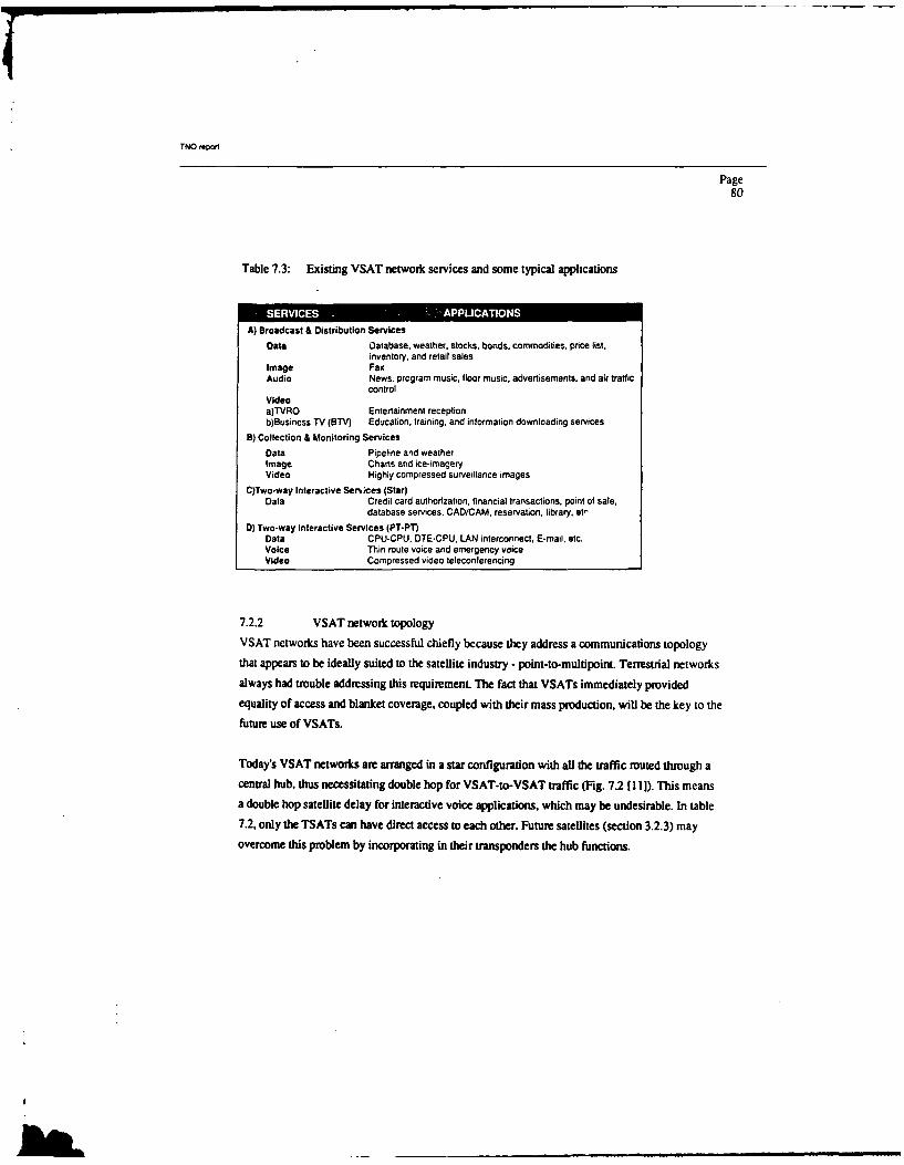
TNO repon
Page80
Table 7.3: Existing VSAT network services and some typical applications
A) Broadcast & Distribution Services
Data Oatabase. weather, stocks, bonds, commodities, price list,inventory, and retail sales
Image FaxAudio News. program music, floor music, advertisements, and air traffic
controlVideoa)TVRO Entertainment receptionb)Business TV (BTV) Education, training, and information downloading services
B) Collection & Monitoring ServicesData Pipeline and weatherImage Charts and ice-imageryVideo Highly compressed surveillance images
C)Two-way Interactive Sen ces (Star)Data Credit card authorization, financial transactions, point of sale,
database services, CAD/CAM, reservation, library, et,
D) Two-way Interactive Services (PT-PT)Data CPU-CPU, DTE-CPU, LAN interconnect, E-mal. etc.Voice Thin route voice and emergency voiceVideo Compressed video teleconferencing
7.2.2 VSAT network topology
VSAT networks have been successful chiefly because they address a communications topology
that appears to be ideally suited to the satellite industry -point-to-multipoint. Terrestrial networks
always had trouble addressing this requirement. The fact that VSATs immediately provided
equality of access and blanket coverage, coupled with their mass production, will be the key to the
future use of VSATs.
Today's VSAT networks are arranged in a star configuration with all the traffic muted through a
central hub, thus necessitating double hop for VSAT-to-VSAT traffic (Fig. 7.2 [11]). This means
a double hop satellite delay for interactive voice applications, which may be undesirable. In table7.2. only the TSATs can have direct access to each other. Future satellites (section 3.2.3) may
overcome this problem by incorporating in their transponders the hub functions.

TNO repo'
Page81
MOST COMPUTER
REMOTE USER VSAT
REMOTE USERTERMINAL CENTRAL HUB
Fig. 7.2: Today's VSAT network
7.2.3 The use of VSATs
In Europe, the use of VSATs certainly lags behind that in the U.S.. There is however a significantdemand for cross-national data distribution in Europe, particularly within the multi-nationals. This
follows from a study commissioned by Eutelsat with CAP Scientific, London.
As far as the equipment is concerned, implementation of VSAT systems would be no problem inEurope. The frequency band used is the Ku-band. The technology is already that advanced thatthis band gives no difficulties. Ku-band is chosen above L-band, which was primary at firstinstance, because of the far greater transponder availability, the wider frequency band allocations,and lack of terrestrial interference [8]. In contrast to the use of interactive VSAT systems in theUnited States, the broadcast mode is likely to be the most important to European users. There aremany large database system operators that are extremely interested in VSATs. The demand forhigh reliability in broadcast mode requires the system protocols to be verified. There have beentried several U.S. VSAT systems in Europe, as currently there are only a few known Europeanmanufacturers, but the U.S. systems currently available do not satisfy these requirements. Few

TNO report
Page82
protocols have been verified and designed with fault tolerance in mind, so this remains atechnological problem, along with perhaps a range of LAN interfaces.
In order to convince potential European users of the capabilities of VSAT systems, someEuropean finns have build the first European VSAT network in a co-operative projecL Thecentral hub station is located in France while the microstations are in Athens, Hanover, Cologne,Madrid and Paris. The network was used for data broadcast and embedded in an Electronic Mail
system.
While VSAT vendors are trying to improve the technology and productivity, service providers areengaged in developing new applications to exploit the full potential technology and expand themarket base. In [10] three potential new applications are presented:
I. Flexible interconnecting between Local Area Networks (LANs) and Metropolitan AreaNetworks as well as gateway access to centralized information databases and computing
services by realizing a VSAT-based Satellite Wide Area Network (SWAN)2. The potential provision of ISDN compatible services via VSATs both in conjunction with
existing satellites as well as future Advanced Satellites (ADSAT) having on-board switching
and processing capabilities3. The use of VSATs to solve backhaul interconnecting/intemetworking problems associated
with evolving Mobile Satellite (MSAT) communications networks (for example a vehicle
operator who has an MSAT network to communicate with the vehicles but wishes to be ableto communicate with his customers at the same time)
If the interested reader wants to get more acquainted with the subject of VSATs the references [8]and [101 to [24] are strongly recommended. In the next section advanced satellite concepts will be
discussed. They will open up new possibilities for MSAT and VSAT networks.
7.3 New technologies
In the previous section it is stated that VSATs provide corporations with a cost effective method
of collecting large amounts of random data from large numbers (possibly thousands) of locations.These networks, because they bypass the terrestrial system and are cost effective, are growing
rapidly. However, the VSAT system is not effective in terms of voice traffic which still comprises
approximately 85% of all traffic. This limitation on voice traffic is a function of the delay due to
bilk.

TNO report
Page83
the double hop communications. Another limitation is attributed to the amount of cost effective
throughput possible. A non-processing satellite, i.e., bent pipe, cannot support the high data rate
requirements desired by businesses on small terminals and be cost effective [25].
Several countries have initiated programs to develop those satellite capabilities required to make
them competitive with terrestrial technologies in the next decade. The three Key technologies that
are being developed are: electronically hopped or scanning spot beam antenna systems, satellite-
based electronic circuit switches, and intersatellite communication links, primarily laser based
with data rates in the several Gbps range. Of course, these techniques could also serve the voice
traffic of the international telephony links. Applying intersatellite links, bulk traffic could be
supported with only one satellite hop from one point to every point on earth.
7.3.1 Spot beam antennasMost present domestic satellites have antennas that produce only a few shaped beams that cover
one or more nations. A typical antenna gain corresponding to such beams is 33 dB, dropping to 27
dB at the edge of the c,'erage. Replacing this antenna configuration with one that produces
multiple spot beams (muld provide an additional gain of 10-20 dB per beam. The additional gain
is limited by the difficulties in launching antennas with very large diameters. To overcome this
difficulty, unfurlable antennas could be used such as applied on NASA's ATS-6 satellite [261.
In addition to the higher gain, multiple beams have the advantage of using spatial separation. By
using spatial separation the same frequency band can be used in geographically separated beams,
thus increasing the bandwidth availability by several fold. The beams can be geographically fixed
or hopping (to reduce the required number of satellite receivers, transmitters, etc.). In a hopping
system, each of M independent beams continuously hops to N different locations. A virtualpattern of MxN spots will be the result. A hopping-beam system offers the possibility to
dynamically adjust the dwell time in each location depending on the demand for traffic at that
location, thus optimizing !he use of the system's capacity.
In Fig. 7.3 [11] on the next page the difference between a conventional and a future satellite is
shown. Table 7.4 compares single and multiple beam satellites.

TNO report
Page84
MULTIPLE SEAM SATELLITE
CURRENT DOMESTIC SATELLITE
Fig. 7.3: Multiple beam satellite vs. current single beamsatellite
Table 7.4: Comparison of single beam and multiple beam satellite antennas
Parameter Conventional FutureSingle beam satellites Multiple beam satellites
Power flux density Low, HighThe energy is spread Focused high EIRP spot beams
Spectrum efficiency Low HighCannot reuse frequency Spatial diversity enables frequency(except by polarization) reuse among spot beams
Feed/antenna Simple feed Complex feed arra and beamcomplexity forming networks
Payload complexity/ Simple transponders Complex onboard processing andinterconnecti'ity switching to allow signal flow
among beams

TNO repot
Page85
It is obvious that the use of hopping beams requires a TDMA access scheme, which implies more
expensive groundstations. Earth stations for TDMA are always more expensive than thosesupporting FDMA (and providing the same bandwidth) because a higher transmit peak power forthe high data rate TDMA burst is necessary (available power and data rate are very dependent on
each other, which is made clear in section 3.1.4).
Producing multiple spot beams has several consequences for the satellite. The satellite antennashave to be large, there have to be complex beam forming networks, and there is a need for a
muting mechanism on board the satellite.
7.3.2 Satellite-based switchingThe routing mechanism on board a multiple beam satellite can be dynamic or static. Dynamic
muting can be accomplished by using fast switches or by using multiplexers (FDM or TDM).Static routing can be done by using a matrix of filters and by cross strapping transponders. Fornext generation satellites this will be already a large improvement in respect of the bent-pipe
single beam satellites of today. The flexibility of dynamic routing however offers much morepossibilities. Two switching approaches can be distinguished: Intermediate Frequency (IF)switching and baseband switching. It leads to Satellite Switched TDMA (SS/TDMA) (section
2.4.3).
If the switching is baseband, the satellite is inherently a regenerative satellite. It requires
demodulation/remodulation in the switching process. For VSAT network star topologies thismeans that functions of the central hub station are lifted on board the satellite. This implies thatdouble satellite hops will be past time because it enables VSATs to communicate directly to each
other. For voice applications this will be very practical because of the reduced time delay. Animportant disadvantage is however that the transmit rate will be fixed after the satellite launch.
Fig. 7.4 [27] shows an advanced communication satellite on board processing repeater. A verysophisticated technology is presented in [27], were optical technologies for signal processing in
satellite repeaters are discussed.

TNO reporI
Page86
LL DE $WSW FH
ISM .E D@" Mom. tWMooX tow)*
&JF COM
0P *"COMB Co.~matM.
SI. flWSt~t* UB Li T , j FO LO
-MX W u "'Ue DIP ..
Fig. 7.4 Advnce cmM 9ommnicto satellit on1 brdW
IPraelt links are define as, folow [9
inesatl it lWSik (IMs have also bee calecosknk
"WhatIS~si do4 istAnsform d communication satellite hic todabsclyrpaes
intoa itrcolnksnece globale detorkmnthusyicaios cbee useits lonectwomseparaton
comuicinssatellite lnsaedfnewoas expandin th[fe29ecvrgefrechsse.Thycnb
usorusaceon veie onicons. Thanisg will bfecome movre morat asysma movedeeper

TNO repot!
Page87
into space. One of the more near term applications is in telemetry and control systems. The need
for a series of earth stations around the globe to control satellites can be replaced by ISLs."
There can be distinguished two means of implementing ISLs, millimetre wave (MMW)
technology and laser technology. MMW technology is of lower risk than optical ISL technology.
Design issues concerning MMW technology are frequency, antenna positioning, acquisition and
tracking, antenna type, power amplification, and link analysis. Frequencies are mostly above 30
GHz, allowing small directional antennas and high bitrates.
The laser technology tends to be regarded as a less mature technology than MMW ISL
technology. It has a high potential though, especially for requirements of higher data rates. A high
gain can be achieved with small reflectors. This allows the transmitter and receiver to be small
and lightweight with low power consumption. Optical links also provide a high degree of privacy
in communication and are largely immune from electrical interference. Design issues concerning
laser technology are laser source, optical detector, and tracking and acquisition [30].
7.3.4 Conclusions
The experimental satellites of today (NASA's ACTS, ESA's OLYMPUS and NASDA's (National
Space Development Agency of Japan) ETS-VI [31]) incorporate many of the technologies that
will be important to future satellite systems and VSAT systems in particular. For experimenters in
Europe the Olympus satellite is at the moment the most important one [32].
The shifting pattern of satellite usage can be summarized as follows [33]:
- telephony: the current declining rate of growth for trnnking in the face of cable competition
may eventually become an overall downturn, although this can be in part offset by
concentration on rural telephony and services for the developing world;
- mobile satellite services: an area ripe for growth into the next century as existing maritime
services are joined by aeronautic and land-mobile systems of steadily evolving complexity and
coverage;
- business services: the highly lucrative VSAT revolution has been cited as the short-term
saviour of the SATCOM industry - its expansion in the US continues, in Europe the explosion
is only just beginning,

TNOepor
Page88
TV services; full-time and occasional satellite use for TV distribution continues to expand in
these TV- and channel-mad times - cable and Direct Broadcast Satellite (DBS) activity should
serve to increase the importance of TV to the satellite industry.

TNO r40 ni
Page89
7.4 References
[1] Jim Chalmers, "No time to dwell on history", Communications Engineering International,
January 1990
[2] Isolde Goggin, "An examination of the possibilities of satellite communications with
small mobile earth stations", Rev. FITCE (Belgium), vol.23, no.4, p.2 7 -4 4 , Oct.-Dec.
1984
[3] W. Rafferty and K. Dessouky, "RF Development for Mobile-Satellite Systems", MSN &
CT, November 1988
[4] R.Rogard, "A Land-mobile satellite system for digital communication in Europe",
Proceedings of an ESA Workshop on Land-Mobile Services by Satellite, held at ESTEC
on 3-4 June 1986 (ESA SP-259, Sept. 1986)
[5] Olof Lundberg, "Satellite Communications - The Crystal Ball Becomes Clearer", SEA
Technology, May 1988
[6] Marc van der Heyden, "Mobile schaduwnet via de satelliet", Telecommagazine nr.4, juni
1988
[71 "Die "Wunderkinder" der Szene", Funkschau 21/1989
[81 Leonard S. Golding, Andrew J. Viterbi, Richard W. Jestin, Joseph N. Pelton, Barry G.
Evans, Joseph Rinde, Peter P. Nuspl, Pierre Bartholorne, K.M. Sundara Murthy, "VSATs:
Expert Views On Future Trends", IEEE Communications Magazine, May 1989
[9] Bert Wiggers and Marc van der Heyden, "Digital mobile telephone network threatened
from space?". Telecommagazine, Autumn 1988
[101 K.M. Sundara Murthy and Kenneth G. Gordon, "VSAT Networking Concepts and New
Applications Development", IEEE Communications Magazine. May 1989

TNO repon
Page90
[11] F. Michael Naderi and William W. Wu, "Advanced Satellite Concepts for Future
Generation VSAT Networks", IEEE Communications Magazine, September 1988
[12] D. Chakraborty, "VSAT Communications Networks - An Overview", IEEE
Communications Magazine, Vol. 26, No. 5, May 1988
[13] X.T. Vuong, kF.S. Zimmermann and T.M. Shimabukuro, "Performance Analysis of Ku-band VSAT Networks, IEEE Communications Magazine, Vol. 26, No. 5, May 1988
[14] D. Raychaudhuri and K. Joseph, "Channel Access Protocols for Ku-band VSATNetworks: A Comparative Evaluation", IEEE Communications Magazine, Vol. 26, No. 5,
May 1988
[15] Dattakumar M. Chitre and John S. McCoskey, "VSAT Networks: Architectures,
Protocols, and Management", IEEE Communications Magazine, Vol. 26, No. 7, July
1988
[16] Jim Stratigos and Rakesh Mahindru, "Packet Switch Architectures and User Protocol
Interfaces for VSAT Networks", IEEE Communications Magazine, Vol. 26, No. 7, July
1988
[17] Barry Jagoda, "VSAT to TSAT: a step ahead", Communications International, November
1988
[18] Edwin B. Parker and Joseph Rinde, '"rransaction Network Applications With User
Premises Earth Stations", IEEE Communications Magazine, September 1988
[19] Alan L. McBride and Christopher V. Cook, "VSAT Maintenance and Installation", IEEE
Communications Magazine, September 1988
[20] Ranjana Sharma, "VSAT Network Economics: A Comparative Analysis", IEEE
Communications Magazine, February 1989

TNO repot
Page91
[21] K.M. Sundara Murthy, Jay Alan, John Barry, Barry G. Evans, Neville Miller, Robert
Mullinax. POaul Noble, Barry O'Neal, Joseph J. Sanchez, N. Seshagiri, Dennis Shanley,
Jim Stratigos and John W. Warner, "VSAT User Network Examples", IEEE
Communications Magazine, May 1989
[22] Manfred K. Schudat, "Data Distribution via Satellite Using Very Small Aperture
Terminals", Mikrowellen Magazin, Vol. 14, No. 4, 1988
[23] Dr. Just-Dietrich Biichs, "Kieine Stationen fUr groBe Datenmengen", Funkschau 16/1989
[24] Ralf C. Hilke, "VSAT-Netze in Europa", ntz Bd. 43 Heft 3, 1990
[25] Stephen Clark Homer, "An Examination of the Advanced Communications Technology
Satellite (ACTS) and its Application to the Defense Data Network (DDN)", United States
Military Academy, 1976
[26] J.R. Norbury, "satellite land mobile communication systems", Electronics &
Communication engineering journal, NovemberT)ecember 1989
[27] Fulvio Ananasso and Ian Bennion, "Optical Technologies for Signal Processing in
Satellite Repeaters", IEEE Communications Magazine, February 1990
[281 V.W.S. Chan, "Intersatellite Optical Heterodyne Communication Systems", The Lincoln
Laboratory Journal, Volume 1, Number 2, 1988
[29] Richard S. Fuhnnann, University of Miami, "Intersatellite link design issues", Thesis
submitted to the University of Colorado, 1985
[30] O.B. Milits-Lacroix and G. Berretta, "Optical Inter-Satellite and Inter-Orbit Links - The
Critical Aspects", ESA Bulletin 54, 1988
[31] Jim Chalmers, "Japan's satellite challenge", CEI, June 1989

TNO repvwt
Page92
[32] J.H. Paul, "The Large Telecommunications Satellite 'Olympus"', ESA Bulletin 58, 1989
[33] "Satcomms: the bandwagon becomes a business", Communications Engineering
International, February 1988

TNO report
Page93
8 OVERVIEW OF MILITARY SATELLITE COMMUNICATION SYSTEMS
This chapter gives an overview of the military Air, Land and Sea SATCOM systems of the
several nations. An important source of information was reference [1), chapter 5, which describes
on a global level the various communication satellites developed by the U.S. Department of
Defense (DoD), joint programs with Britain and the North Atlantic Treaty Organization (NATO),
and the British military satellites (Skynt). The U.S.S.R. satellites are described in [1], chapter 6.
References to more detailed articles, reports and conference proceedings am included in this
chapter as well.
8.1 United States
8.1.1 IDCSP
The United States started military satellite communications with the launch of t'e IDCSP (Initial
Defense Communication Satellite Program) satellite in 1966. It was a very simple repeater with
no telemetry, tracking and command possibility. The single transponder had two Travelling Wave
Tubes (TWTs), one on and one standby. The satellite could support three kinds of two-way
circuits: up to 5 commercial quality voice, or 11 tactical quality voice, or 1550 teletype. A total of
26 IDCSP satellites have been launched from 1966 to 1968.
8.1.2 TACSAT
The IDCSP satellites however could not support tactical satellite communications, therefore DoD
initiated the development of TACSAT. Although much more advanced, no flight model was
assembled because of funding limitations and the qualification model was the one launched. The
satellite was aimed for a complementary function of the IDCSP satellites, which could only
support strategic communications between large groundstations. TACSAT was designed for
operation with small land-mobile, airborne, or shipbome tactical terminals. The qualification
model was used extensively for military applications, especially in the UHF range (225-400
MHz).
8.1.3 DSCS II
DoD notified that the IDCSP satellites (at that time called Phase I of the Defense Satellite
Communications System (DSCS)) could fulfil certain military needs. Therefore Phase I1 was
started with the development of the DSCS II satellites. The DSCS II satellites are significantly

TNO report
Page94
different from the IDCSP satellites, but are still able to intemperate with the Phase I ground
terminals. The communications payload consists of two earth coverage antennas and two narrow
beam antennas. The subsystem includes preamplifiers that can be switched to various gains to
allow either linear or saturated operation of each channel. The orbital locations of the satellites are
the Atlantic, East Pacific, West Pacific, and Indian Ocean.
8.1.4 FLTSATCOM and AFSATCOMAfter the end of life of the Tacsat experimental satellite (and also the Lincoln Experimental
Satellites LES-5 and LES-6) there was a need for continuation of tactical satellite
communications. Therefore the DoD developed the GapflIer/FLTSATCOM system.
FLTSATCOM serves Navy surface ships, submarines, aircraft, and shore stations. AFSATCOMserves Air Force strategic aircraft, airborne command posts, and ground terminals. The twosystems share a set of four FLTSATCOM satellites in geostationary orbits. To provide coverage
of the polar regions, the Air Force also has communications equipment packages on severalsatellites in high inclination orbits.
The FLTSATCOM satellites have three antennas: one for UHF transmissions, one for UHFreception and one for SHF transmission/reception (X-band, 7-8.4 GHz). SHF communicationsimply reception of the fleet broadcast uplink and transmission of a beacon. The antenna
configuration supports 23 channels. Channel I is for X-band uplink to UHF downlink, 25 kHzbandwidth (1200bps composed of 15 teletype and one synchronization channel at 75 bps each).Channels 2-9 are 25 kHz bandwidth fleet relay channels (each channel is a 1200- or 2400-bps
link). The Air Force will use channels 11-22 of 5 kHz bandwidth for narrowband communications
(a single 75-bps link per channel) and channel 23 for wideband (500-kHz) communications
(multiple FDMA links at 75 bps or a single higher rate link). The fleet broadcast and some AirForce narrowband uplinks can use processing receivers on board the satellite, which provides
some anti-jam capability.
AFSATCOM would not be able to communicate in polar regions without some UHF packages onother DoD satellites in highly inclined orbits. In addition, AFSATCOM uses a single channel
transponder with antijam improvements on DSCS III satellites.
Satellites 7 and 8 have an additional EHF communications package with a 44 GHz uplink and 20GHz downiink. This package is called FEP (FLTSATCOM EHF Package) and is developed by

TNO report
Page95
Lincoln Laboratory [2]. T'he FEP has facilitated the early operational test and evaluation of the
Milstar (section 8.2.2) EKE/SHF terminals being developed by the Army, Navy, and Air Force. It
has both earth coverage and spot beam antennas and is able to demodulate up to 32 received
signals (EDMA uplinks), process them, reformat them, combine them into a single TDM data
str, and modulate them for downlink transmission. Uplink and downlink are frequency
hopped. Fig. 8.1 [ 1] shows the complete FLTSATCOM Communication Subsystem, including the
EHF package on satellites 7 and 8.

TNO ,epowt
Page96
STUTHE
UNNFNC
mAlm Ot&%R AAOt 0U1ANNL ANTENNA IPAPASOLAI
f~L -
Fig S I FLSACO Cmunao Subsste

TNO 'eport
Page97
8.1.5 DSCS 111 (13], [4], [51)
With the deployment of the DSCS III system there has been an increase in both the number and
variety of terminals. While the DSCS IH satellites were developed to serve long distance
communications between major military locations, the DSCS III satellites were developed to
operate in an environment where the majority of the DSCS terminals is small, trnsportable, or
ship-borne.
The first DSCS III satellite is launched in 1982 and is operational at 135°W longitude. The
communication subsystem has three receive and five transmit antennas that can be connected in
various ways to the six transponders. Fig. 8.2 on the next page shows the DSCS III
communications subsystem [I ]. Each transponder can be configured to serve a specific type of
user requirement. The total configuration includes the choices of receiving antenna, transmitting
antenna, transponder gain level, and linear, quasilinear, or limiting mode of the preamplifiers.
There are two earth coverage and one multibeam receiving antennas. The multibeam antenna
(MBA) can form any beam of arbitrary size, shape and location by means of a beam-forming
network that controls the relative amplitudes and phases of each of the 61 individual beams. It can
also form nulls in selected directions in order to counter jammers.
The five transmitting antennas are divided into two earth coverage antennas, two 19-beam
transmit MBAs and one steerable dish antenna (parabola, 3 degrees beamwidth). The earth
coverage antennas are horns, just like the earth coverage receiving antennas. The 19-beam
transmit MBAs have the same capabilities as the receive MBA (except nulling) although their
resolution is lower. The steerable dish antenna generates a single beam with high EIRP.
Fig. 8.2 also shows the AFSATCOM single channel transponder (SCT) that has its own UHF
transmitting and receiving antennas, but can be connected to the X-band earth coverage or MBA
receiving antennas. It is a regenerative transponder that demodulates the received uplink and
remodulates it for transmission and that can also store messages for repeated transmission. The
demodulation process provides some antijamming protection to the uplink.

TNO rwv'1
Page98
cc us R O VIAO we I
- IRAI1WA)IFN nLW a~ 6
?S PAINAw AT I IW
To H s 8"PP1
SC - .o
IT c~~IM.lO -I~U OP O M6 l M AMK I a
Fig ~ r S2 DCIlComnc Tio sse
Th -®rIIstliehsaTeeer.Takn n omnd(TC)sbytmwihinotshwnin ig 82. he'I Csubytmoeae tSbndfrluc n aelt
houskeepng ~'rvses.It peraes a X adtruhteSFcm uiain ala ocontrol~T of thMaelt omnctoscniuain
tmut e oedtht h ky eaue f hiatelt sye is h alxbecm uiain
operation afore bthoprtoofhemtiam ntna.Teaiiyo h Bstprvdeaspcaizdan aloe cvrgealosa omniaioscpaiit ositntwtanticipatedT NAT reureet fo h orhgnrto AT mnctosstlie
)Alsatlie ha"0Yve oefn fttmiy4rcig4n omn sbytmt xvd oto n oioigostiesau n ooti aafo hc h aelt oiincnb opldjAPNI

TNO repon
Page99
8.1.6 TDRSS [6]
The role of the Tracking and Data Relay Satellite system (TDRSS) is to increase the volume and
frequency of communications between orbiting spacecraft and the earth. The system provides for
almost continuous communications connectivity between shuttles and satellites in low-earth orbit.
and their command and control elements below. The system will serve defense as well as civilian
agencies.
The Tracking and Data Relay Satellites (TDRS) serve as relay platforms that receive and
retransmit data produced by other spacecraft. With the TDRS, space shuttles and other spacecraft
are in communication with the ground for nearly 90 percent of their flight time, compared to only
15 percent before the launch of the TDRS. The TDRSs are the largest, most complex
communications spacecraft in orbit, and they can relay voice, television, digital and analog
signals.
2 @ Mtu KI liS t
A~ (TORSS SRl"
Fig. 8.3: The Tracking and Data Relay Satellite [ 6
8.1.7 Navstar1"PS
Navstar Global Positioning System (GPS) is a space-based radio navigation system designed to
allow an unlimited number of users to passively receive precise position, velocity and time
information anywhere on or above the earth's surface [7]. A secondary mission of GPS is to detect
IS-

TNO ,&Nnw
Page100
nuclear bursts in or above the atmosphere. The range is determined by the propagation delay of
the signals from thm satellites, which assumes knowlegde when they were transmitted. This
timing information is calculated by using the propagation delay of the signal from a fourth
satellite 18]. The satellites are in an inclined orbit that takes them over any point in their ground
track approximately every 12 hours (Fig. 8.4 [8]).
46 AP217I
V-4 10
Fig. 8.4: The GPS satellites
Authorized (military) users will have access to the Precise Positioning Service (PPS), which will
provide accuracies of 10 to 20 meters (95 percentile level), depending on the platform dynamics.
Civilian users will have access to the Standard Positioning Service (SPS), which will provide 100
meter accuracy [9].
A technical description of the system can be found in [8]. Almost at of the GPS satellites ar
placed in orbit at the moment. OPS is expected to find wide-spread use in marine, land, and air
applications, since it will meet all but the most stringent navigation requirements.
L3
t1
17[ W~gM% '20 1

TNO WW01
Page101
8.1.8 Ground mobile forces satellite communications
The Ground Mobile Forces Satellite Communications (GMFSC) system is the Tactical satellitecommunications (Tacsatcom) system of the US Army. An important feature of Tacsatcom is thatcommunications can begin within 30 minutes after arrival between command posts and individual
terminals.
A typical deployment of a corps/division network consists of a single control terminal (MSQ- 114)
and a network of hub-spoke type arrangements as shown in Fig. 8.5 [10]. A hub-spoke typearrangement would be representative of a corps/division GMFSC network and would consist ofone nodal terminal (AN/rSC-85A) and four non-nodal terminals (AN/rSC-93A).
Fig. 8.5: Ground Mobile Forces tactical satellitecommunications network
The Ground Mobile Forces (GMF) integrated Sill antijam modems into their system to allowmultichannel critical communications over extended distances and varied terrain. The SlHF
modems use direct sequence spread spectrm. If communications have been lost to a hostileelectronic warfare jammer within the network's range, the anti-jam system responds. One by one.

TNO report
Page102
each of the Ground Mobile Force (GMF) terminals can be brought back into the network through
the antijam (AJ) control terminal modem. Antijam communications can be established with up to
50 terminals in a given network.
After deployment of the terminals, the Tacsatcom network will have achieved the long sought-
after goal of providing a single highly mobile and flexible communications system that is suited
for the battlefield environment and that provides connectivity to a range of tactical and strategic
forces.
8.2 NATO
The first phase (1967) of the NATO communication satellite program was the experimental use of
the United States IDCSP satellites with two ground terminals [I 1. The second phase started in
1970 with the launch of the first NATO satellite, called NATO II. The UK began a parallel
program with the Skynet II satellites, which were very similar to the NATO I1 satellites. At this
moment the NATO II satellites are still in orbit but not in use anymore and the current operational
satellite is NATO I11.
The NATO Ill satellite has three communication channels with 17, 50 and 85 MHz bandwidths.
The channels are received through a widebeam coverage horn antenna. It covers the North
Atlantic region including the east coast of North America, all of Western Europe, and the
Mediterranean. At the transmit end, the 50 MHz channel is transmitted through a widebeam path
(same coverage as the receiving antenna), while the other two channels are combined in a
narrowbearn path (Western Europe coverage only). The coverage patterns are shown in Fig. 8.6
[I], which also shows the location of the large static ground terminals that provide the strategic
traffic connectivity.

TNO 'epo.!
Page103
80.
0Z NARROWBEAM'
rCOVERAG-
20'V0 E20" -- " COVERAGEI
0.
120" 100" 80" 60" 40" 20* 0 20" 40" 60"WEST EAST
0 NOMINAL SATELLITE LOCATION* GROUND TERMINALS
Fig. 8.6: NATO coverage and terminal locations
Most of these ground terminals, of which one is the main control centre and one is the alternate
control centre, have 42 feet antennas. They provide mainly digital voice communications and
share the satellite by FDMA.
Four NATO III satellites have been launched. NATO IliA to D. At the moment NATO IIIC is
providing the active role in the system. The satellite communication system is a pan of the NATO
Integrated Communications System (NICS), which also has various terrestrial communications
links and switching and control nodes [121.
NATO IliA is out off service at the moment. NATO IIIB will be used for experimental purposes.
This satellite has also been used to serve DSCS needs until four DSCS I satellites were available.
NATO II1D is kept in semi-dormant storage. It was placed in orbit because of the delay in the

TNO repor
Page104
NATO IV program, but it could probably remain an in-orbit spare as the NATO IV satellite will
be launched at the end of 1990.
8.3 United Kingdom ([ 13],[14],[15])
The UK SKYNET I satellite was the world's first geostationary defense satellite (launched in
November 1969). It had a single earth coverage antenna and provided 3 W output from a hard-
limiting transponder. The power was divided between 2 MHz and 20 MHz channels.
The next UK military satellite, SKYNET JIB, was larger and the communications payload used a
16 W TWTA. The antenna system was again a single earth cover antenna. The satellite is still
operating and used for R&D purposes.
The SKYNET Ill programme was cancelled on the grounds that the UK's requirement for satellite
communications could be more cost-effectively met through joining the US DoD and NATO
programmes. The more and more important role of small aperture, low data rate terminals for
ship-bome use and tactical land use however, together with the increasing pressure on available
US and NATO resources, was responsible for the decision in 1981 to start the Skynet 4
programme.
Skynet 4 is economically developed from a family of successful civil satellites (the European
Communications Satellite (ECS)). The program includes two satellites and maybe a third will
follow. It has a strong system resistance to all forms of electronic warfare and other military
threats, achieved by hardening, nulling of unwanted signals and general signal processing.
Skynet 4 is interoperable with U.S. and NATO systems. It provides strategic/runk links, serves
multiocean maritime operations and provides comprehensive tactical communications via
transportable and mobile stations [16][17][18], including individual manpacks [191120][21][221
and, eventually, aircraft terminals [14]. A high flexibility is needed to meet this range of user
requirements in terms of satellite EIRP, data rate, access schemes and resistance to jamming. It is
achieved through a selection of antenna coverage, channel gain setting and detailed, flexible
access planning.

TNO repot
Page105
The Skynet 4 satellite uses two UHF earth cover channels (250/300 MHz) and four SHF channels
in the 7/8 GHz band with a total bandwidth of 340 MHz provided by three 40 W TWTAs. Two
TWTAs are for the UHF channels of 25 kHz bandwidth each, giving an effective isotropic
radiated power of 26 dBW. It provides a facility for experimental communications in the EHF
band as well. The antenna coverage of the four SHF channels is shown in Table 8.1 [15].
Table 8.1: Some SHF frequency operating parameters
ANTENNA COVERAGE E1RP dBW Bandwidth MHz
Spot 39 60Narrow 34 85Wide 35 60Earth 31 135
In the ground terminals of the Skynet 4 system many modem techniques are applied. The use of
phased array antennas for example offer many advantages in the airborne application. The
antennas can be shaped to conform to aircraft surfaces to minimise drag, and can also provide for
dynamic adaptive pattern control to alleviate multipathjamming effects and improve sidelobe
performance. Substantial development work in monolithic microwave integrated circuit (MMIC)
devices is being carried out to make phased array solutions a practical option for the airborne role.
Minimizing the microwave devices is necessary because of the large number of integrated
transmit/receive/phase-shifting elements in phased antennas and their controlling network.
8.4 USSR
8.4.1 Moiniya [23]
The U.S.S.R. began to develop communication satellites early in the 1960s with the Molniya
(Lightning) communication satellites used for both civilian and military communications. A total
of almost 100 Molniya satellites have been launched in the well-known Molniya orbit. Very little
details about these satellites are known. The first design can relay a single television signal (40 W
output power) or duplex narrowband (e.g. telephone or telegraph) transmissions (14 W output
power). It is not possible to determine how the design has changed during the years.

TNO eport
Page106
The groundstations have antennas of 40 feet in diameter. They form together the Orbita network.
Apparently some functions of the Orbita network have been transferred to the Stationar satellites
in recent years.
8.4.2 Stationar [24]
The Stationar satellites have a geostationary orbit. The satellites operate in the 5.7 to 6.2 GHz and
3.4 to 3.9 GHz bands. The system provides global coverage, although most of these satellites are
positioned to serve the U.S.S.R. and neighbouring countries. Coverage of the U.S.S.R. requires at
least two satellites. It seems that the Stationar satellites are used for civilian purposes. The three
different kinds of Stationar satellites are called Raduga, Ekran and Gorizont.
8.4.3 Other satellites
The Soviet satellite program is vast. A large fraction is directly related to military objectives. The
Soviets pay more attention to the amount of spacecraft in orbit, whereas the Western bodies have
technologically very advanced satellites. However, the Soviet satellite is becoming more
advanced too.
A four-satellite geosynchronous Gals system uses the 7-8 GHz band. They have ten narrowband
channels, with three or four receivers and transmitters. Antenna patterns include earth coverage,
northern hemisphere, and a spot beam with about 5 degrees beamwidth.
The Soviets have also a satellite for mobile communications (Volna). The two channel L-band
equipment are for aeronautic service and for maritime service. The land mobile force is served by
a UHF channel.

TNO eport
Page
107
8.5 References
[1] D.H. Martin, "Communication Satellites 1958 to 1986", the Aerospace Corporation, El
Segundo, Calif. 90245, October 1984
[2] W.W. Ward and F.W. Floyd, "Thirty Years of Research and Development in Space
Communications at Lincoln Laboratory", The Lincoln Laboratory Journal, Volume 2,
Number 1, 1989
[3] D.J. Welde, General Electric Company, "DSCS III -- Flexible Communications",
Conference Proceedings of the Military Electronics Defense Expo, September 1979
[4] William J. Hilsman and Alfred R. Garcia, Jr., "Defense Satellite Communications
System: Another Milestone", Signal. September 1983
[5] "Navy SHF Satellite Communications System Description", Naval Ocean Systems
Centre, San Diego, California 92152, November 1983
[6] Floyd C. Painter, "The Tracking and Data Relay Satellite System", Defense Electronics,
June 1989
[7] "Navstar Global Positioning System", The C31 Handbook, Edition Three, prepared by the
Editors of DEFENSE ELECTRONICSEW Communications, Inc. 1] 70 E. Meadow Drive, Palo Alto, California 943034275
USA, 0 1988
[8] Philip G. Mattos, "Global positioning by satellite", Electronics & Wireless World,
February 1989
[9] Per K. Enge, Rudolph M. Kalafus and Michael F. Ruane, "Differential Operation of the
Global Positioning system", IEEE Communications Magazine, Vol. 26, No. 7, July 1988
[10] Robert A. Bagnell, "Super High Frequency Tactical Satellite Communications Comes of
Age", Signal, November 1989

TNO repw
Page108
[11] Franco Controtti, "NATO SATCOM - Past, Present and Future", NATO's Sixteen
Nations, September 1988
[12] John Anderson, "The Evolution of NATO's new integrated communications system",
NATO's Fifteen Nations Special 2,1980
[13] P.J. Skilton, "Tactical UK military satellite ground terminals - a research and
development review", Royal Signals and Radar Establishment, Copyright C Controller
HMSO London, 1989
[14] D. Cummings and C.G. Wildey, "Military aeronautic satellite communications", IEE
Proceedings, Vol. 133, Pt. F, No. 4, July 1986
[15] G.O. Graydon, "The Skynet 4 System", Signal, October 1989
[16] N.P.K. Mortensen, "Stability and Pointing Accuracy of a Tactical Satellite
Communications Antenna", International Conference on Antennas and Propagation,
York, March-April 1987
[17] Sidat M.S., Davis I., Brain D.J.: "Steerable, Low-Profile, Stabilised Antenna for a Mobile
SATCOM Terminal", International Conference on Antennas and Propagation, York,
March-April 1987
[181 Owens R.P., Smith A.C.: "Dual Band, Dual Polarised Microstrip Antenna for X-Band
Satellite Communications", Military Microwaves Conference, Brighton, June 1986.
[19] P.J. Skilton and A.S. McK. Anderson, "A folding antenna for SHF SATCOMS", IEE
Colloquium Digest No. 1987/62, May 1987
[20] Jones C.H.: "A Manpack Satellite Communications Earth Station", Rad. & Elec. Eng., 5 1,
No. 6, 259-271, June 1981.

TNO report
Page109
[21] Skilton P.J., Westall I.L.: "MANPACK SHF Satellite Ground Terminal", Military
Microwaves Conference, London, 1982.
[221 P.J. Skilton, A.C. Smith, "Miniature Portable Satcom Terminals", IEE Colloquium Digest
No. 1986/118, 11 November 1986.
[23] G.E. Perry, "The Molniya Communications Satellites", Royal Air Force QUARTERLY.
17, page 154-162, Summer 1977
[24] G.E. Perry, "Russian Ocean Surveillance Satellites", Royal Air Force QUARTERLY, 18,
page 60-67, Spring 1978
[25] "The Soviet military space progran", International Defense Review, 2/1982

TNO rep't
Page110
9 THE FUTURE OF MILITARY SATELLITE COMMUNICATIONS
9.1 Shortcomings of the current satellite communication system
Although the military satellite service can provide communications for strategic traffic between
fixed earth stations, the military mobile satellite service is very limited in its capacity at the
moment
For example, the US UHF system cannot provide simultaneous communications on different
channels for a large number of users. This can be explained by the following link budget
calculation for the downlink from a military UHF satellite (FLTSATCOM) to a small UHF earth
station [1].
Table 9.1: Link budget calculation of the downlink from a US maritime satellite (frequency is240 MHz)
Radiated power by satellite (e.i.r.p) e.i.r.p. 26.0 dBW
Free-space path loss (L) +L -172.8 dB
Receiver antenna gain (G) +( +0.0 dB
Receiver noise temperature MT) -T -30.8 dB
Boltzmann's constant (k) -k +228.6 dBW/K.Hz
Fade margin (M) -M -4.0 dB
Required energy per bit-to-noise density -Eb/No -10.0 dB
for an error rate of l0 (Eb/No)
Available data rate (R) R 37.0 dB.sec"1
The data rate R is equal to 5 kbits/sec (lO-0.0). This is barely enough to support two vocoded
voice channels (A vocoded voice channel is produced by means of a special "vocoder" which
produces 2400 bits/sec digital voice. The intelligibility of such a signal is good, but the person
who speaks cannot easily be recognized from his voice). Telex messages are therefore the bulk of

TNO report
PageIll
traffic since they only require a capacity of 75 bits/sec. For transmissions to the total of more than
thousand UHF-terminals the broadcast mode can be used, while the terminals can report back by a
time division multiple access (TDMA) scheme.
The limited capacity is not the only drawback of UHF communications. The jamming protection
is marginal because the UHF terminals have modest e.i.r.p. and limited bandwidth available for
spread-spectrum techniques. Narrow beams can only be achieved with very large antennas at
UHF, so for small terminals the beamwidths are very wide and therefore UHF communications
can easily be detected. High-altitude nuclear explosions can cause long periods of outage,
resulting from absorption and scintillation effects. The periods of outage are proportional to the
frequency, so better performance can be expected at SHF or EHF frequencies [2].
The SHF system provides significantly more capability in the above mentioned areas at low to
medium data rates. The available bandwidth at the 7-8 GHz band is large in respect to the military
UHF frequencies (225-400 MHz). The e.i.r.p. is much larger because the antenna gain is
proportional to the square of the frequency. For the downlink it will improve the antenna gain by
10log(7GHz/24OMHz) 2 = 30 dB which means a factor thousand increase of available bandwidth
if the receiver size and noise temperature is the same as in UHF (in fact the noise temperature will
be much lower because of the narrower beam, causing less influence from ground noise, see
section 3.1.3.1 of this report).
The satellites for SHF communication however are mainly used for strategic traffic. If the military
community wanted to make full use of the capabilities of satellite communications, there would
be a need for a dedicated mobile communication satellite. In the near future some new satellite
systems are expected. They will enhance the capacity and survivability of the current systems and
therefore the capability to support mobile communications, although they ar not dedicated
mobile communication satellites. NATO will enhance its capacity and survivability to that of the
US DSCS III system and the UK Skynet 4 system with the NATO IV satellite, while the US is
developing an extremely survivable satellite system named Milstar.

TNO nowwt
Page112
9.2 Future developments
9.2.1 Transition to mobile communications with NATO I1
In the NATO IV time-frame we will see the use of a greater amount of small ground terminals
which are transportable or mobile. Current areas of research are therefore concentrated on
minimizing the size of the elements of the ground stations. Areas of interest are:
hybrid solid state power amplifiers (with respect to TWTs, they are lightweight and reliable).
Microwave Monolithic Integrated Circuits (MMIC's), to provide militarized Low Noise
Amplifiers (LNAs), mixers and oscillators.
phased array antennas.
modem equipment (capable to cope with doppler effects and to acquire fast acquisition while
providing anti-jam resistance).
Demand Assignment Multiple Access (DAMA) protocols for multiple users and low data rate
(several hundreds of bps).
Reference is made to the publications of the Royal Signals and Radar Establishment (RSRE)
research projects on portable and manpack terminals [3]-[ 11.
9.2.2 Future U.S. military strategy
The U.S. military strategy is in a transition period at the moment. The emphasis will be on
attaining a more balanced military capability to deal with a wider range of contingencies across
the spectrum of conflict, and satellite communications systems (with Milstar at the forefront) will
be a major ingredient of this new realignment. It will provide more flexible and interoperable
capabilities which are required by lower intensity conflicts.
Milstar will operate in the extremely high frequency (EHF) band. Several options exists to
extending this EHF service to low intensity conflict [12]:
- development of small, portable EHF terminalb ':ompatible with existing and planned space
segments
- extension of the Milstar architecture by adding compatible EHF transponders on other host
satellites
- evolution toward a more integrated satellite architecture based on Milstar concepts and
technology.
:i _

TNO repor
Page113
9.2.3 Optical satellite communications
Optical satellite communications are very interesting for military satellite communications. These
could be used for intersatellite links and space-to-ground communications [13]. The benefits of
optical satellite communications would be a very good Low Probability of Exploitation (LPE) by
adversaries, through the very narrow beamwidths, small antenna apertures, wide bandwidth
capability, and potentially good jamming resistance.
It has also been suggested that the use of blue-green light may permit communication to
submarines below the sea surface. A Submarine Laser Communications (SLC) system would
represent the most complex communications system known to man. The operational value would
be very large: a transmitted laser signal from a satellite is able to penetrate sea water to depths of
hundreds of feet. The optical link enables a high data rate. These two facts make SLC very
attractive as a submarine command and control link. With this capability, submarines are allowed
to operate at optimum depth and speed [14).
9.3 Future satellite systems
9.3.1 NATO SATCOM Phase IV
NATO recently decided to place into orbit a new family of two satellites designated as NATO IV.
The programme is carried out in co-operation with the UK, because for NATO IV the UK Skynet
4 design was selected. The satellites were originally planned for the 1987-97 time-frame, but the
first launch has been postponed to 1990 [15].
The antenna coverage has slightly changed with respect to Skynet 4 to fulfil specific NATO
needs. The coverage is more Europe oriented with respect to the UK Skynet 4 satellite. It does not
contain the EHF package of Skynet.
Like Skynet 4 the satellite will be hardened against the effects of nuclear detonations in space. As
such the satellite was designed to survive system-generated electromagnetic puls (EMP) and high
doses of radiation. It will have features to counter the effects of enemy jamming (antenna nulling
and signal processing). It is capable of supporting both strategic and tactical communication links
through the much more sophisticated transponder with respect to the NATO III transponder (more
power, more bandwidth and more downlink beams including earth coverage and spot beams).
LIIL

TNO
Page114
9.2.2 Milstar
In the early 1980s a major system improvement was planned by the US DoD for the 1990s. This
resulted into the Milstar (MILitary Strtegic/TrActical and Relay) system, which is now being
prepared for deployment [16].
Milstar will provide both tactical and strategic service for mobile users. The space assets will be
in both low and high inclination orbits (fig. 9.1 [171). As such it enables a global coverage without
single vulnerable nodes. Intersatellite links at 60 GHz will provide network flexibility. As the
earth's atmosphere is effectively opaque to transmissions at 60 GHz, these links cannot be
jammed by large ground stations, nor can they be intercepted. Milstar provides EHF and UHF
communications. The EHF uplink frequency is 44 GHz and the downlink frequency is 20 GHz
which is in fact in the SHF band.
The UHF communications payload is for compatibility with the approximately 1200 currently
deployed UHF terminals. For broadcast applications the UHF-band can very well be used in
combination with the EHF-band. For this application the EHF-band can best be used on the
uplink, which is under the most serious threat, because an EHF uplink can very well be protected
by a wideband spread-spectrum waveform. The antenna systems of most satellites face hostile
territory and uplink jamming is therefore possible by means of a large ground station, while
downlink jamming requires the adversary to approach very close to the ground stations. In the
satellite, the waveform is demodulated and despread, before remodulating it on a UHF downtink
where the bandwidth is too small for spread spectrum techniques.

TNa ro
Page115
MiatarTechniog@ OHFFREQUENCIES
-increased Bandwkdth-Narrow Seems-Smalle Terminals
0 ADAPTIVE ANTENNAS-U~plink Nulling--Seabl DwmiNks
* SIGNAL PPROCESSING4-Autonmoua Oprto
-Increaaed Anti-jamn1 -Croabanding Capabiity
Fig.TA 9.:C'LTRcmmncdn ocp
SITE T CS2PN COORADO

TNO mpon
Page116
Milstar will use the EHF band for the following reasons [181: EHF can overcome frequency-
congestion difficulties for unprotected communication links. For jam-protected links EHF
supplies the bandwidths necessary to implement robust, anti-jam systems based on spread-
spectrmn technologies. Because the antenna gain rises proportional with the square of the
frequency, small antennas can be used which implies a modest-sized satellite. The narrow beam
gives a low probability of intercepted transmissions from terminals that wish to remain unnoticed.
EHF has also some disadvantages. The most important ones are the effects of rain attenuation on
link operation at EHF which require that - to minimize outage - the minimum elevation angle of
the satellite relative to the terminal must be significantly higher than for lower-frequency systems.
Milstar uses therefore high inclination orbits, next to the geostationary ones, to extend the
coverage to the polar regions.
Milstar is designed from start to finish as a warfighting system. Major development efforts
include: reliable, "low-risk" travelling wave tube amplifiers, fault tolerant spaceborne computers,
advanced adaptive antennas, nulling antennas, hardened electronics and high-speed processors,
protection from physical attack (including nuclear hardening), "low cost" small EHF terminals
(terminal antennas will be in dish configurations and range in size from about I ft. to 5 ft. in
diameter), low-noise amplifiers and high-speed LSI circuits that can provide the terminals with 44
GHz uplink nulling on jammers [17].
The system's design stresses survivability over capacity. Milstar will handle only I megabit of
data per second, and no more than 15 users will be able to simultaneously access each satellite.
The system is virtually unjammable through the use of frequency division multiple access uplinks
with frequency hopping over the entire bandwidth of IGHz. The satellites are not only placed in
high supersynchronous orbits to provide hemispherical line-of-sight, but also to provide a degree
of protection from anti-satellite weapons, which are nominally designed to destroy satellites in
low to medium orbits [19]. A high degree of flexibility is reached by steerable downlink antennas
and the ability to handle traffic multiplexed by time-division multiplexing and frequency-division
multiplexing methods. Milstar will prove its value in times of war or international crisis. It will
supplement rather than replace existing DoD communications satellites (20].

TNO report
Page117
9.2.3 Lightsat
Lightsat is a program to develop inexpensive, lightweight satellites. A theoretical application of
lightweight satellite technology is: Multichannel EHF communications, which means that
Lightsats compatible with Milstar communications satellite ground elements could supplement or
replace a damaged Mfilstar constellation. Ughtsats could provide "crisis augmentation" and a"surge capability" to reconstitute critical functions if anti-satellite weapons would be used against
the existing constellations of large, expensive satellites.
Because only three of the 10 Milstar satellites initially planned have been funded, it is hoped by
some that Lightsats might fill the void. The future for Lightsat however is far from certain due to
fluctuating funding and a vulnerability to budget cuts [21].

' TNO repo l
Page
118
9.3 References
[1] Pravin C. Jain, "Architectural Trends in Military Satellite Communications Systems",
Proceedings of the IEEE, Vol. 78, No. 7, July 1990
[2] William E. Leavitt, Phillip M. Hooten, et al, "A Comparative Study of SHF and EHF
Satellite Communications", Volume I, Martin Marietta Corporation, Information and
Communication Systems, Washington, D.C. 20024, September 1987
[31 P.J. Skilton, "Tactical UK military satellite ground terminals - a research and
development review", Royal Signals and Radar Establishment, Copyright C Controller
HMSO London, 1989
[4] D. Cummings and C.G. Wildey, "Military aeronautic satellite communications", tEE
Proceedings, Vol. 133, Pt. F, No. 4. July 1986
[5] P.J. Skilton and A.S. McK. Anderson, "A folding antenna for SHF SATCOMS", lEE
Colloquium Digest No. 1987/62, May 1987
[6] N.P.K. Mortensen, "Stability and Pointing Accuracy of a Tactical Satellite
Communications Antenna", International Conference on Antennas and Propagation,
York, March-April 1987
[7] Sidat M.S., Davis I., Brain D.J.: "Steerable, Low-Profle, Stabilised Antenna for a Mobile
SATCOM Terminal", International Conference on Antennas and Propagation, York,
March-April 1987
[8] Jones C.H.: "A Manpack Satellite Communications Earth Station". Rad. & Elec. Eng., 51,
No. 6, 259-271, June 1981.
[9] Sklton PJ., Westall I.L.: "MANPACK SHF Satellite Ground Terminal", Military
Microwaves Conference, London. 1982.
1101 Owens R.P., Smith A.C.: "Dual Band, Dual Polazised Microstrip Antenna for X-BandSatellite Communications", Military Microwaves Conference, Brighton, June 1986.
a

TNO reot
Page119
[111] PJ. Skilton, A.C. Smith, "Miniature Portable Sateom Terminals", lEE Colloquium Digest
No. 1986/118, 11 November 1986.
(12] Dr. Kostas Liopims and Dr. Edward Lam, "Extremely High Frequency Satellites Offer
Flexibility", Signal, July 1990
[13] T.C. Tozer, "An introduction to military satellite communications", RSRE memorandum
No. 3976, Royal Signals & Radar establishment, Procurement executive, Ministry of
Defense, RSRE Malvern, Worcs, November 1987
[14] Floyd C. Painter, "Submarine Laser Communications", Defense Electronics, June 1989
[15] Franco Controtti, "NATO SATCOM - Past, Present and Future", NATO's Sixteen
Nations, September 1988
[16] D.H. Martin, "Communication Satellites 1958 to 1986", the Aerospace Corporation, El
Segundo, Calif. 90245, October 1984
[17] James B. Schultz, "Milstar to Close Dangerous C31 Gap", Defense Electronics, March
1983
[18] W.W. Ward and F.W. Floyd, "Thirty Years of Research and Development in Space
Communications at Lincoln Laboratory", The Lincoln Laboratory Journal, Volume 2,
Number 1, 1989
[19] James W. Rawles, "Milstar Fights for Survival", Defense Electronics, March 1990
[20] James W. Rawles, "Milstar Soars Beyond Budget and Schedule Goals", Defense
Electronics, February 1989
[21] James W. Rawles, "A Big Boost for Lightsat?", Defense Electronics, March 1990

TNO ,epe
Page120
10 COMPARISON OF CIVIL AND MILIARY SATCOM SYSTEMS
In civil systems all kinds of communications can be recognized, but the bulk of the traffic isgenerated in the international trnk circuits to support voice communications, and televisionbroadcasts requiring approximately 30 MHz of bandwidth (5MKz video signal FM modulated).
Military satellite communications are generally longe-range systems that frequently involve linksbetween deployed forces and the continent [ 1]. For these systems light, transportable terminals arenecessary that provide: coverage, rapid deployment, mobility, and physical and electronicsurvivability. To ensure continuous coverage for bombers and submarines operating near theNorth Pole, also highly elliptical orbits are used where geosynchronous satellites would be belowthe horizon [2]. These properties are needed during low intensity conflicts. When a full-scaleconflict occurs the terminals and the satellites have to operate in a nuclear environment.
10.1 Threats and countermeasures
Military satellite communications are mainly distinguished from civil systems by the need forsurvivability under threat. Physical threats, like explosives and high-powered lasers [31 are fairlyobvious. In military systems, as much as possible redundancy is provided. It is thought to be moreeffective to use a lot of small, inexpensive terminals than only a few, physically protected,expensive ground stations. Only the large anchor ground stations (supporting the telemetry,tracking and command of the satellite, the higher capacity strategic links, and the traffic handlingto mobile earth stations) are hardened against EMP and physical attacks. Diversification of thelarge anchor stations is desirable.
10.1.1 Nuclear thucat
Nuclear weapons pose special threats. They could destroy complete ground stations or satellites,bit also cause dangerous radiation, electromagnetic pulse (EMP), and atmospheric ionisation (hassevere influence on propagation characteristics).
Protection against radiation or EMP is Called 'hardening! of the satellite. The influence ofatmospheric ioniisation on propagation characteristics can be countered by using higherfrequenicies. The periods of outage in a nuclear environment are about 2.5 times shorter at 20 GHzthan at 8 0Hz [4]. The currently developed military system Mlilstar therefore uses these high
>4
I - --I

TNOreport
Pag,:121
frequencies (44 GHz uplink and 20 GHz downlink). Higher frequencies also provide a larger
available bandwidth and smaller beamwidths, providing a low probability of intercept (LPI) of the
ground station by an enemy [5). A low probability of intercept is essential in preserving the
ground stations fron any attack.
10.1.2 Jamming
Another threat to a military communications system is jamming. Jamming may be either exploited
on the uplink or the downlink. Uplink jamming is considered to be a serious threat, as most
satellite receive antennas view hostile territory. Because the telemetry and command system is
vital to the housekeeping and the positioning of the satellite, the Tr&C uplink is the first
communications link to be protected. Jammers can be countered by antenna nulling and spread-
spectrum techniques.
One way to realize antenna nulling is shown in fig. 10.1 [6], where the output from a spot-beam
antenna is subtracted from that of an earth cover antenna with a wide beamwidth. This technique
is fundamentally similar to that of the interferometer, where a signal is received by two identical
antennas, whose outputs are subtracted after imposition of a phase shift
EARTH COVERAGE BEAM
RESULTANT
(EC-SPOT)Ii "SPOTBEAM
ANGLE
Fig. 10.1: Illustration of antenna nul realisation
rI

TNO repor
Page122
Spread spectrum techniques rely on the user spreading his signal with a spreading function
which cannot be replicated by an enemy. Through the despreading operation at the receiver any
uncorrelated interference such as jamming is spread, and the bulk of it is removed by the filter.
The amount by which the carrier-to-interference ratio has increased by this process is called the
processing gain. The concept is illustrated in fig. 10.2 [6].
Narrow Band Data Signal.
Multiplied by Spreading kHz -
Code to give Wide
Bandwidth Signal.
MHz
Transmitted. and subject
to Jammer.
but Jammer
At Receiver Correlated now Spread.
with same tpreadlng Code.
Data Signal Despread.
Narrow Filter passes Data.
Little Jammer
! Power remains.
Advantage of Processing
Gain.
Fig. 10.2: Jamming protection through spread spectrum
AW

TNO repor
Page123
The two basic spread spectrum techniques are direct sequence and frequency hopping. The direct
sequence technique is explained in section 3.4.3.2, in the discussion on CDMA. Frequency
hopping requires the carrier frequency to jump in discrete hops over a wide bandwidth; the
receiver recovers the signal by hopping its local oscillator in synchronism. The advantages and
disadvantages of these both spread spectrum techniques are described extensively in [71. Hybrid
forms of direct sequence and frequency hopping are also possible and will combine the
advantages of both systems.
10.2 Comparison of the Intelsat V and the DSCS III satellite
To compare the civil and military satellite communications it is illustrative t - -nsider a recent
civil and a recent military satellite of approximately equal weight an( size. Two satellites, namely
the Intelsat V (commercial) and the DSCS III (military) satellite have a weight of 2200 lb resp.
2475 lb and are both 3-axis stabilized, which in general means stabilization in pitch, roll and yaw
through thrusters or spinning wheels. The Intelsat V has a rectangular body of 5,4x5,8x6,6 ft and
the rectangular body of DSCS III is 6x6x7 ft. The configuration of the communications channels
is tabled below (8].
Table 10.1: Channel configuration of Intelsat V and DSCS III
Intelsat V DSCS III
6/4 GHz: 21 single conversion repeaters Six channels: 85-MHz bandwidth (channel 3).with bandwidths of 36 to 77 MHz, 50-MHz bandwidth (channel 6),dual beam and dual polarizatin 60-MHz bandwidth (channels 1,frequency reuse 2.4.5)
14/11 GHz: 6 double conversion repeaters withbandwidths of 72 to 241 MHz,dual beam frequency reuse
Since the power of the TWTs of Intelsat V has to be divided between a lot of channels, 21
channels at 6/4 GHz, the transmitted EIRP per channel is low with respect to that of the DSCS III
satellite. The strongest 6/4 GHz channel.on Intelsat V has an e.i.r.p. of 29 dBW. In contrast,
DSCS III has TWTAs of 40 Watts available for channel I and 2 and a high gain multiple beam
antenna as well as a steerable dish antenna which provide channel I and 2 with 40 dBW
(multibeam antenna) and 44 dBW (dish antenna).

TNO ,@pot
Page124
The 14/11 GHz channels on Intelsat V which are for television transmissions also have a high
e.i.r.p of 41.1 dBW for the west spot and 44.4 dBW for the east spot antennas (see Fig. 6.1 for the
coverage patterns). The TWTA has only 10 Watts available (6 dB less than the 40 Watts of DSCS
III), but dish antennas that have about the size of the DSCS III steerable dish antenna have a 4 dB
higher gain at 11 GHz than at the military downlink frequency of 7 GHz.
The different values of e.i.r.p have direct consequences for the earth terminals and applications.The Intelsat V 6/4 GHz band supports mainly the international voice-traffic on point-to-point
links between large earth stations of 10 to 30 metres. Its nominal capacity is 12.000 two way
voice circuits. By means of the 14/11 GHz band it can support two television transmissions. Thesatellite is also capable to provide low data rate services to fixed small users (business services). It
is not tailored to support communications to very small mobile earth stations at 6/4 GHz. Thiscould however be accomplished by the maritime communications subsystem at L-bandfrequencies, 1.5/1.6 GHz, on the Intelsat VM satellite (not mentioned in table 5.1, since it is asubsystem specifically leased to Inmarsat) and the new Inmarsat standard C ground station.
The military DSCS III satellite is able to support all types of communications in one frequency
band (7.25-8.4 GHz). Even communications with portable earth stations are possible. Military
communications however suffer from capacity problems. The reuse of frequencies by means of an
antenna system with two orthogonal polarizations is not possible, because of the different signal
strengths coming from the ground terminals. Isolations between orthoganal polarizations of about30 dB can be achieved, but the differences between signal strengths from small and large
terminals can be larger. A further reduction of capacity is caused by the need for electronic
counter counter measures (ECCM) techniques to reduce the effects of jamming. The spread-
spectrum techniques used for this purpose require a lot of bandwidth.
Further differences between the satellites are found in the antenna system. The hemisphere beam
antennas of Intelsat V have 88-horn feeds. With such feeds the antenna pattern can be changed byswitching the right horns on or off. They are necessary to be able to adapt the hemisphere beams
according to the regions they have to cover at both sides of the Atlantic 6r Indian Ocean (see Fig.
6.1).

TNO report
Page125
The DSCS III satellite also has multibeamn antennas, one multibeam receiving antenna with a 61 -
horn feed and two multibeam transmitting anteras with 19-horn feeds. The beams shapes can be
dynamically adjusted by electronic control of the relative amplitudes and phases of each of the
61 (or 19) individual beams. The receiving antenna can even generate nulls in selected directions
in order to degrade the effects of jammers.
The DSCS III satellite system is therefore very flexible: it can adapt to reconfiguration of the
ground terminals/network by changing the coverage, it can support mobile communications and
provides electronic survivability. Of course the satellite is hardened, to provide physical
survivability as well.
A closing comparative statement can be made as follows: the military satellite offers a high
degree of flexibility and survivability, while the civil satellite offers much capacity on fixed
communications links. In respect to the flexibility aspect of civil satellite systems this statement is
becoming untrue for modem and future satellite systems. The flexibility that SATCOM systems
can provide will be the right to exist for future civil satellite systems.

TNO repor
Page126
10.3 References
[I1 Dr. Kostas Liopiros and Dr. Edward Lain, "Extremely High Frequency Satellites Offer
Flexibility", Signal, July 1990
[21 James W. Rawles, "Milstar Soars Beyond Budget and Schedule Goals", Defense
Electronics, February 1989
[3) Leonard H. Perroots, "Soviet Beam Weapons are Near Tactical Maturity", Signal, March
1990
[4] William E. Leavitt, Philip M. Hooten, et al, "A comparative Study of SHF and EHF
Satellite Communications (U)", Martin Marietta Corporation, Information and
Communications Systems, 475 School Street, SW, Washington, D.C. 20024, September
1987
[5] P.J. Skilton, "Tactical UK military satellite ground terminals - a research and
development review", Royal Signals and Radar Establishment, Copyright C Controller
HMSO London, 1989
[61 T.C. Tozer, "An introduction to military satellite communications", RSRE memorandum
No. 3976, Royal Signals & Radar establishment, Procurement executive, Ministry of
Defense, RSRE Malvern, Worcs, November 1987
17] H.J. Dekker, "Toegepaste ECCM technieken in SHF SATCOM modems en hun
eigenschappen", Fysisch en Elektronisch Laboratorium TNO, Augustus 1990
[81 D.H. Martin, "Communication Satellites 1958 to 1986", the Aerospace Corporation, El
Segundo, Calif. 90245, October 1984

TNO reponI
Page127
11 CONCLUSIONS
Through the study of satellite communication systems and the investigation on the future
developments an insight on satellite communications is obtained which has led to the following
conclusions:
General
Satellite communication systems can provide the benefits of global coverage, flexibility,
mobility, communication to low density population areas, provision of private networks, and
heavy trunk connections.
During the first decades the systems were not developed to a stage in which land mobile and
aeronautic satellite communication systems would be efficient in terms of size and cost. But
now the emphasis in both civil and military satellite communication will be more on mobility
and flexibility, because fibre optics will decrease the need for fixed high capacity satellite links
like the international point-to-point trunks for telephony and telegraph.
Civil satellite communications
With respect to land mobile satellite communications in Europe there is expected a market for
specific applications that cannot be served by the terestrial networks adequately, such as
private mobile communications networks for truck companies.
At the moment land mobile and aeronautic satellite communication systems still are an
emerging technology. Recent improvements however in transmitting, receiving and modem
equipments have led to a reduction of the size of the earth stations, while cheaper components
enable a lower price. In the United States this has already brought forth the exploitation of
very small aperture terminal (VSAT) systems with earth station antennas of about I m in
diametre. The earth stations can easily be installed and are transportable.
VSAT networks are a very good solution for applications, where cost stability and control, the
potential for enormous network growth and reconfiguration flexibility, and independance are
important benefits. VSATs are able to provide point-to-multipoint connections (e.g.

TNO epo
Page128
broadcasting for data gathering purposes) very easily whereas this always has been a problemfor terrestrial networls.
- In VSAT-networks the star-network concept is used wherein the VSATs communicate with arelatively large central "hub" earth station. Point-to-point connections between VSATs areonly possible for low data rates because of the limited antenna gain and power of the satellitesof today. For communications between VSATs therefore a double hop through the satellite viathe hub is necessary. Three new key technologies which are in an experimental stage couldsolve this non-effectiveness in providing voice communications and limited amount of costeffective throughput possible of VSATs; electronically hopped or scanning spot beam antenna
systems, satellite-based electronic circuit switches, and intersatellite communication links.
Military satellite communicationsThe military requirements impose specific requirements to the military communications
satellite. Survivability to potential threats like physical attacks (by providing redundancy),dangerous radiation caused by nuclear weapons (by "hardening" the satellite) and jamming (byemploying spread-spectrum techniques and antenna nulling) is a prime requirement. A militarycommunications satellite has to be very flexible because it has to handle a variety of differentearth stations over a wide area. The earth stations can be different in power, traffic andmodulation scheme and they can be mobile, transportable or fixed.
UHF-SATCOM is very limited in its survivability and capacity and therefore there is a needfor small and transportable/mobile ground terminals at SHF or EHF. These frequency bands,especially the EHF band, are much more suited to overcome frequency congestion ofunprotected links and to provide a low probability of signal interception and resistance to
jamming.
Optical satellite communications techniques could meet the military requirements even better.They could permit virtually unjammable communication, a very high information transfer ratebetween satellites and reduce the dependence of vulnerable ground relays. Opticalcommunications techniques are however in an experimental stage.

TNO reoi
Page129
12 BIBLIOGRAPHY
This report gives a very general view on satellite communications. For the reader that is interestedin more detailed information, or specific subjects, the following books are worth reading.Especially the CCIR handbook covers the various items on satellite communications extensively.
CCIR, "Handbook on satellite communications (Fixed satellite service)", ITU, Geneva, 1988
W.L. Pritchard and J.A. Sciulli, "Satellite communication systems engineering". Prentice Hall,
1986
V.K. Bhargava et a]., "Digital communications by satellite", Prentice Hall, 1977
B.G. Evans, editor, "Satellite communication systems", Peter Peregrinus Ltd., 1987
J. Spilker, "Digital communications by satellite", Prentice Hall, 1977
K. Feher, "Digital communications, satellite/earth-station engineering", Prentice Hall, 1983
K. Miya, "Satellite communications technology", K.D.D. Inc., Japan 2nd edn., 1985

TNO ropor
Page130
LIST OF ABBREVIATIONS
ACTS Advanced Communications Technology Satellite
ADPCM Adaptive Differential Pulse Code Modulation
ADSAT Advanced Satellites
AFSATCOM Air Force Satellite Communication
BSS Broadcasting-Satellite Service
CDMA Code Division Multiple Access
CES Coast Earth Stations
DAMA Demand Assignment Multiple Access
DBS Direct Broadcasting Satellite
DCME Digital Circuit Multiplication Equipment
DM Delta Modulation
DoD Department of Defense (of the United States)
DSCS Defense Satellite Communications System
e.i.r.p. and EIRP Equivalent Isotropically Radiated Power
ECCM Electronic Counter-Counter Measures
ECS European Communications Satellite
EHF Extremely High Frequency
EMP Electromagnetic Puls
EPIRBs Emergency Position Indicating Radio Beacons
ESA European Space Age-t.v
ETS Experimental Test Satellite
FDM Frequency Division Multiplexing
FDMA Frequency Division Multiple Access
FEP FLTSATCOM EHF Package
FET Field Effect Transistor
FLTSATCOM Fleet Satellite Communication
FSS Fixed-Satellite Service
G/T the figure of merit, which is the receiving antenna gain divided
by the noise temperature of the receiving system
GaAs Gallium Arsenide
GMF Ground Mobile Forces

TNO report
Page131
GMFSC Ground Mobile Forces Satellite Communications
GPS Global Positioning System
HPA High Power Amplifier
IBS Intelsat Business Service
IDCSP Initial Defense Communication Satellite Program
Inmarsat International Maritime Satellite Organisation
Intelsat International Telecommunications Satellite organization
ISLs Intersatellite links
ISS Intersatellite Service
ITU International Telecommunication Union
LAN Local Area Network
LNA Low Noise Amplifier
LOS Line Of Sight
LPE Low Probability of Exploitation
LPI Low Probability of Intercept
MBA Multibeam Antenna
MCPC Multiple Channel Per Carrier
MCS Maritime Communications Sub-systems
MILSTAR MILitary Stategic/Tactical and Relay
MMIC Monolithic Microwave Integrated Circuit
MMW Millimetre Wave
MSAT Mobile Satellite
MSS Mobile-Satellite Service
NASA National Aeronautics and Space Administration (of the United
States)
NASDA National Space Development Agency (of Japan)
NATO North Atlantic Treaty Organisation
NIC Nearly Instantaneous Companding
NICS NATO Integrated Communications System
NOC network Operations Centre
NPR Noise Power Ratio
PCM Pulse Code Modulation
pfd power flux density

INO report
Page132
PPS Precise Positioning Service
PSK Phase Shift Keying
RARCs Regional Administrative Radio Conferences
RF Radio Frequency
RNLN Royal Netherlands Navy
SATCOM Satellite Communication
SCF Satellite Control Facility
SCPC Single Channel Per Carrier
SES Ship Earth Stations
SES Socidtd Europ6enne de Satellites
SHF Super High Frequency
SLC Submarine Laser Communications
SMS Satellite Multi-service System
SOC Satellite Operations Centre
SPS Standard Positioning Service
SS/TDMA Satellite Switched Time Division Multiple Access
SSB-SC Single Sideband Suppressed Carrier
SWAN Satellite Wide Area Network
TACSAT Tactical Satellite
TACSATCOM Tactical Satellite Communications
TDM Time Division Multiplexing
TDMA Time Division Multiple Access
TDRSS Tracking and Data Relay Satellite System
TSAT T-carrier Small Aperture Terminal
TT&C Telemetry, Tracking and Command
TVRO Television Receive Only
TVSAT Television Small Aperture Terminal
TWTA Travelling Wave Tube Amplifier
UHF Ultra High Frequency
USAT Ultra Small Aperture Terminal
VSAT Very Small Aperture Terminal
VSAT(SS) Spread-spectrum VSAT
WARCs World Administrative Radio Conferences
ohm

ThO reow
Page133
In. F.G.J. van Aken TIn J.P. Dezaire
(groupleader) (author)

UNCLASSIFIEDREPORT DOCUMENTATION PAGE (HOD-NL)
1. DEFENSE REPORT NUMBER (MOD-NL) 2. RECIPIENT'S ACCESSION NUMBER 3. PERFORMING ORGANIZATION REPORT
NUMBER
TD90-4049 FEL-90-A338
4. PROJECT/TASK/WORK UNIT NO. 5. CONTRACT NUMBER 6. REPORT DATE
22099 A90KM616 FEBRUARY 1991
7. NUMBER OF PAGES N. NUMBER OF REFERENCES 9. TYPE OF REPORT AND DATESCOVERED
134 (INCL. RDP, EXCL DISTRIBUTION) 142 INTERIM
10. TITLE AND SUBTITLE
CIVIL AND MILITARY SATELLITE COM4UNICATIONS -
A SYSTEMS OVERVIEW AND THE FUTURE DEVELOPMENTS
11. AUTHOR(S)
IR. J.P. DEZAIRE
12. PERFORMING ORGANIZATION NAME(S) AND ADDRESS(ES)
TNO PHYSICS AND ELECTRONICS LABORATORY, OUDE WAALSDORPERWEG 63,2597 AK THE HAGUE,P.O. BOX 96864, 2509 JG THE HAGUE, THE NETHERLANDS
13. SPONSORING/MONITORING AGENCY NAME(S)
HWO KM, P.O. BOX 20702, 2500 ES THE HAGUE
'4. SUPPLEMENTARY NOTES
15. ABSTRACT (MAXIMUM 200 WORDS, 1144 POSITIONS)
THE PROJECT A90KM616, "ORIENTATIE SATCOM", IS BEING PERFORMED ON BEHALF OF THE ROYALNETHERLANDS NAVY (RNLN) TO ASSIST THE NAVY IN THE AREA OF SATELLITE COMMUNICATION. THIS REPORTIS THE RESULT OF THE FIRST PHASE OF THIS STUDY. T E SCOPE OF THE REPORT IS TO GIVE AN OVERVIEW OFTHE PHENOMENON SATELLITE-COMMUNICATION.
THE RESULT OF THE STUDY IS A GENERAL INSIGHT IN SATELLITE COMMUNICATIONS FOR BOTH CIVIL ANDMILITARY APPUCATIONS. SOME EXAMPLES OF APPLICATIONS ARE; INTERNATIONAL TELEPHONY, TELEVISIONBROADCASTING, SMALL PRIVATE BUSINESS NETWORKS. AND MOBILE (AT THE MOMENT STILL PRINCIPALLYMARITIME) COMMUNICATIONS. IN THESE APPUCATIONS SATELLITE COMMUNICATION SYSTEMS PROVIDE AGLOBAL COVERAGE AND A HIGH FLEXBIUTY.
THE SCIENTIFIC ARTICLES HAVE NOT BEEN CONSIDERED BECAUSE IN THIS STAGE IT WAS NOT THE INTENTIONTO STUDY THE BROAD AREA OF TECHNIQUES ON A SPECIALIST LEVEL. MAGAZINES, BOOKS AND A NUMBEROF REPORTS OF UNIVERSmES AND RESEARCH INSTITUTES HAVE BEEN THE MAIN SOURCES OF INFORMATION.THEY AFFORDED AN UNDERSTANDING OF THE EXISTING SYSTEMS AND AN INSIGHT IN THE FUTUREDEVELOPMENTS.
16. DESCRIPTORS IDENTIFIERS
SATELLITE COMMUNICATION DITTOCOMMUNICATIONS SATELLITESCOMMUNICATION NETWORKSPOINT TO POINT COMMUNICATION
l7a. SECURITY CLASSIFICATION 17b. SECURITY CLASSIFICATION 17c. SECURITY CLASSIFICATION
(OF REPORT) (OF PAGE) (OF ABSTRACT)
UNCLASSIFIED UNCLASSIFIED UNCLASSIFIED
10. DISTRIBUTION/AVAILABILITY STATEMENT 17d. SECURITY CLASSIFICATION
(OF TITLES)
UNLIMITED AVAILAIUTY UNCLASSIFIED
UCLIED
i i


