
— Table of contents
004 – 011 Overview
012 – 061 Compression connectors for copper conductors
062 – 065 H-tap connectors
066 Wire joints for copper conductor
067 Cast copper bus taps for copper conductor
068 – 071 Motor pigtail connectors
072– 073 KUBE™ flag and tee connectors
074 – 080 Connectors for aluminum/copper code conductors
081 Transformer lug kits
082 Pin connectors
083 – 084 H-tap insulating covers
085 Parallel splices
086 – 093 Heavy-duty battery/ connectors and tools
094 – 097 Accessories and miscellaneous hardware

B1 copy starts here
B2 copy starts here
B3 copy starts here
4 CO LO R- K E Y E D CO M PR E SSI O N CO N N EC TO R S Y S TEM
—OverviewThe ABB method is better
The ABB method of installing compression connectors on power cables is designed to provide a high degree of reliability in electrical wiring.
A
—01 Strip the insulation—02 Stripping types and conductor connections
—01
—02
Step 1Carefully strip the insulation on de-energized wires to avoid nicking or cutting conductors (wire brush if required).
Stripping types:• A – Strand cut• B – Nicked strands• C – Good strip
Strip the insulation to the proper length so that conductors can be fully inserted into the connector barrel.
Conductor connections:• D – Strip length too long• E – Strip length too short• F – Strip length just right
This method allows electrical workers to make installations with little effort and at a considerable savings in time. The benefit, of course, is a high-quality connection at a low installed cost.
Blackburn® connectors featuring the Color-Keyed system are banded by colored stripes or engraving to indicate location of die on connector for compression. ABB uses full-width and half-width dies dependent on connector size and tool used.
Half-width dies are marked with the letter “H” after the die code number. Refer to the instruction sheet supplied with the connectors for information regarding strip length, die selection and number of compressions required.
—Just four easy steps to a perfect connection!
B C
D E F
5OV ER V I E W
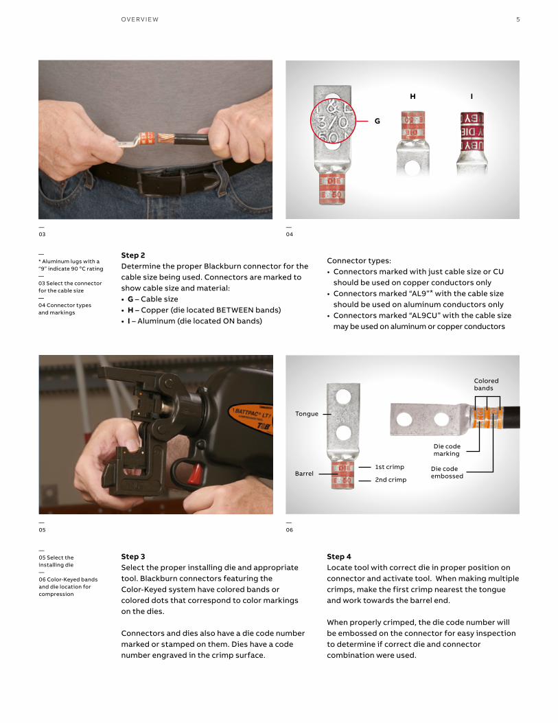
—* Aluminum lugs with a “9” indicate 90 oC rating—03 Select the connector for the cable size—04 Connector types and markings
Barrel
Tongue
1st crimp
2nd crimp
—05 Select the installing die—06 Color-Keyed bands and die location for compression
—03
—04
—05
—06
Connector types:• Connectors marked with just cable size or CU
should be used on copper conductors only• Connectors marked “AL9”* with the cable size
should be used on aluminum conductors only• Connectors marked “AL9CU” with the cable size
may be used on aluminum or copper conductors
Step 3Select the proper installing die and appropriate tool. Blackburn connectors featuring the Color-Keyed system have colored bands or colored dots that correspond to color markings on the dies.
Connectors and dies also have a die code number marked or stamped on them. Dies have a code number engraved in the crimp surface.
Step 4Locate tool with correct die in proper position on connector and activate tool. When making multiple crimps, make the first crimp nearest the tongue and work towards the barrel end.
When properly crimped, the die code number will be embossed on the connector for easy inspection to determine if correct die and connector combination were used.
Step 2Determine the proper Blackburn connector for the cable size being used. Connectors are marked to show cable size and material:• G – Cable size• H – Copper (die located BETWEEN bands)• I – Aluminum (die located ON bands)
G
H I
Coloredbands
Die codeembossed
Die codemarking
B1 copy starts here
B2 copy starts here
B3 copy starts here
6 CO LO R- K E Y E D CO M PR E SSI O N CO N N EC TO R S Y S TEM
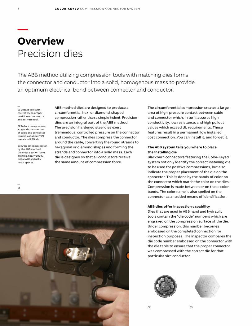
ABB method dies are designed to produce a circumferential, hex- or diamond-shaped compression rather than a simple indent. Precision dies are an integral part of the ABB method. The precision hardened steel dies exert tremendous, controlled pressure on the connector and conductor. The dies compress the connector around the cable, converting the round strands to hexagonal or diamond shapes and forming the strands and connector into a solid mass. Each die is designed so that all conductors receive the same amount of compression force.
The circumferential compression creates a large area of high-pressure contact between cable and connector which, in turn, assures highconductivity, low resistance, and high pullout values which exceed UL requirements. These features result in a permanent, low installedcost connection. You can install it, and forget it.
The ABB system tells you where to place the installing dieBlackburn connectors featuring the Color-Keyed system not only identify the correct installing die to be used for positive compressions, but alsoindicate the proper placement of the die on the connector. This is done by the bands of color on the connector which match the color on the dies.Compression is made between or on these color bands. The color name is also spelled on the connector as an added means of identification.
ABB dies offer inspection capabilityDies that are used in ABB hand and hydraulic tools contain the “die code” numbers which are engraved on the compression surface of the die. Under compression, this number becomes embossed on the completed connection for inspection purposes. The inspector compares the die code number embossed on the connector with the die table to ensure that the proper connector was compressed with the correct die for that particular size conductor.
—OverviewPrecision dies
The ABB method utilizing compression tools with matching dies formsthe connector and conductor into a solid, homogenous mass to providean optimum electrical bond between connector and conductor.
—01 Locate tool with correct die in proper position on connector and activate tool.—02 Before compression, a typical cross section of cable and connector consists of about 75% metal and 25% air.—03 After air compression by the ABB method, the cross section looks like this, nearly 100% metal with virtually no air spaces.
— 01
—02
—03
? ? ? 7
—Quality tooling with the Shure-Stake® mechanism
ABB manual tools with the exclusive Shure-Stake mechanism take the guesswork out of making compression connections. The Shure-Stake mechanism provides a full cycle compression stroke every time. Once the stroke has started, the tool will not release the connector until the proper amount of force has been applied. This is your assurance of a fully compressed connection. ABB compression tools develop uniform, controlled pressure to each connector within their size range. ABB offers electric and battery- powered hydraulic pumps with a Shure-Stake feature that guarantees a full cycle compression.
ABB method components meet industry standardsDepending on the application, all ABB copper connectors meet UL Std. 486A for code stranded and 24 gauge flex, CSA Std. C22.2, No. 65 600 V requirements for power and UL Std. 467, CSA Std. 22.2 No. 0.4 requirements for direct buried grounding.
ABB method connectors are available in a range of sizes and styles to accommodate #8 AWG through 1000 kcmil and larger copper or 2000 kcmil and larger aluminum cable. They may be compressed on cable with either manual or hydraulic tools. They are offered with standard length or long barrels, with one bolt or two bolt holes, or in two-way
styles, for splicing applications. Two-way connectors are compact, providing high pullout values with low resistance.
Blackburn two-hole lugs featuring the Color-Keyed system are ideal for bus bar applications that require two bolts to prevent lug rotation. The ABB method is the most efficient, highest quality connection that has been engineered and delivers the best electrical performance and highest reliability.
ABB compression connectors eliminate risk of problems relating to loose connections when installed properly.
High-grade materials incorporated in ABB methodLow installed cost connections of superior quality can be achieved only through the use of high-grade components. That is an important part of the ABB method – quality products you can depend on.
Copper Blackburn connectors featuring the Color-Keyed system are made of high-conductivity wrought copper, and are electro tin plated to prevent corrosion and to improve conductivity. ABB Blackburn connectors featuring the Color- Keyed system offer the thickest tin plating in the industry. Other copper connectors for heavy-duty use and grid grounding applications are made of high-conductivity cast copper, bright finished.
High-conductivity cast aluminum connectors are available for heavy-duty application.
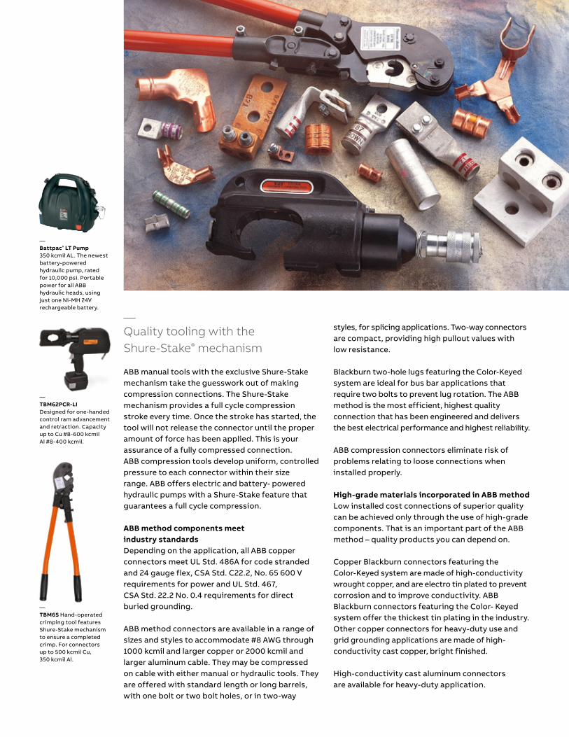
—Battpac® LT Pump 350 kcmil AL. The newest battery-powered hydraulic pump, ratedfor 10,000 psi. Portable power for all ABB hydraulic heads, using just one Ni-MH 24V rechargeable battery.
—TBM62PCR-LIDesigned for one-handed control ram advancement and retraction. Capacity up to Cu #8-600 kcmil Al #8-400 kcmil.
—TBM6S Hand-operated crimping tool features Shure-Stake mechanism to ensure a completed crimp. For connectors up to 500 kcmil Cu, 350 kcmil Al.
B1 copy starts here
B2 copy starts here
B3 copy starts here
8 CO LO R- K E Y E D CO M PR E SSI O N CO N N EC TO R S Y S TEM
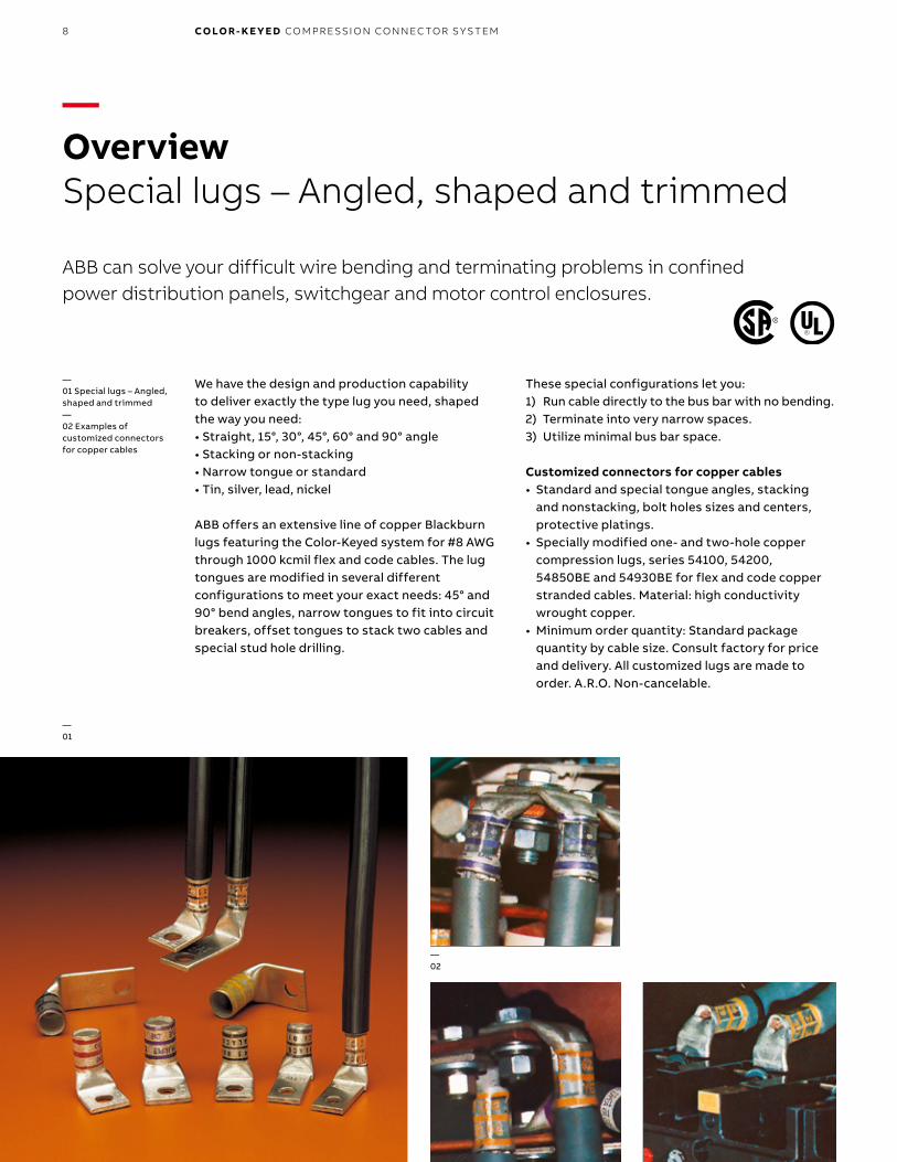
We have the design and production capability to deliver exactly the type lug you need, shaped the way you need:• Straight, 15°, 30°, 45°, 60° and 90° angle• Stacking or non-stacking• Narrow tongue or standard• Tin, silver, lead, nickel
ABB offers an extensive line of copper Blackburn lugs featuring the Color-Keyed system for #8 AWG through 1000 kcmil flex and code cables. The lug tongues are modified in several different configurations to meet your exact needs: 45° and 90° bend angles, narrow tongues to fit into circuit breakers, offset tongues to stack two cables and special stud hole drilling.
These special configurations let you:1) Run cable directly to the bus bar with no bending.2) Terminate into very narrow spaces.3) Utilize minimal bus bar space.
Customized connectors for copper cables• Standard and special tongue angles, stacking
and nonstacking, bolt holes sizes and centers, protective platings.
• Specially modified one- and two-hole copper compression lugs, series 54100, 54200, 54850BE and 54930BE for flex and code copper stranded cables. Material: high conductivity wrought copper.
• Minimum order quantity: Standard package quantity by cable size. Consult factory for price and delivery. All customized lugs are made to order. A.R.O. Non-cancelable.
—OverviewSpecial lugs – Angled, shaped and trimmed
ABB can solve your difficult wire bending and terminating problems in confined power distribution panels, switchgear and motor control enclosures.
—01 Special lugs – Angled, shaped and trimmed—02 Examples of customized connectors for copper cables
— 01
US
— 02

9OV ER V I E W
Notes:
Catalog number: Quantity:
#8 #6 #4 #2 #1 1/0 2/0 3/0 4/0
Code: Weld:
250 kcmil and up (code only)
—Catalog number selection
2-hole 4/0 AWG copper lug basic cat. no.
90° tongue Bottom stack
1⁄4" bolt hole 1" hole spacing
Silver plating
Tongue shape Bolt holes Bolt hole centers Stacking Finish (plating)Inspection hole
(long barrel)Inspection hole
(short barrel)
Type CodeSize
0.020 (in.) CodeDistance
0.015 (in.) Code Type Code Type 1 Code I.D. Code I.D. Code
15o UI #8 0.173 02 1/2 08 Top T** Silver plate SP Peep hole PH Blind end BE
30° UT #10 0.204 03 5/8 10 Bottom B Lead plate LP
45o UF 1/4 0.281 04 3/4 12 Nickel plate NP 150˚
60o US 5⁄16 0.344 05 7/8 14 Plain finish PF
90o UB 3/8 0.406 06 1 16 No marking NM
Blank BT 1/2 0.531 08 11/8 18
(No bolt hole) 5/8 0.656 10 11/4 20
3/4 0.812 12 13/8 22
7/8 0.937 14 11/2 24
1 1.062 16 15/8 26
13/4 28
17/8* 30
2* 32
* These bolt centers not available for bolt holes larger than 13⁄16".** Not required for 45° and 90° top stacking.
— Code table
—OverviewOrder form
Order form (For 54100, 54200, 54800 and 54900 series copper lugs only): Cable:
—2) If either bolt hole size or distance between bolt holes needs to be changed from standard cat. no., both code numbers will appear on the “MADE-UP” cat. no. (See example below)
All “made-up” catalog numbers start with a standard or basic catalog number and are followed by the customer-required extra features: tongue shape, bolt hole size, distance between bolt holes, stacking, plating and inspection hole (peep hole). A code letter or a number has been assigned to each extra feature. See code table.
—Notes: 1) Lack of any of the extra features on the “MADE-UP” catalog number means that the standard cat. no. features are prevalent.
Bolt/Stud Size
Peep Hole Yes
No
Tongue Width
Hole Offset“If required”Bolt Spacing Wrench Clearance
Barrel I.D.
“For Blank Tongue”
Tongue Length
Barrel O.D.Tongue Thickness
Barrel Length
Plus TransitionLong
orShort
Bolt/Stud Size
Peep Hole Yes
No
Tongue Width
Hole Offset“If required”Bolt Spacing Wrench Clearance
Barrel I.D.
“For Blank Tongue”
Tongue Length
Barrel O.D.Tongue Thickness
Barrel Length
Plus TransitionLong
orShort
Tongue Thickness
Tongue Length
Barrel Length
Barrel O.D.
Long
Shortor
Tongue Width
Bolt/stud size
Wrench Clearance
Barrel I.D.
Peep Hole Peep hole
Barrel O.D.Tongue thickness
Tongue length
For blank tongue
Tongue width
Hole offset Wrench clearance
Bolt spacing if requiredPlus transition
Barrel length Long or
Short
Yes No
Diagrams
54212 UB 04 16 B SP
B1 copy starts here
B2 copy starts here
B3 copy starts here
10 CO LO R- K E Y E D CO M PR E SSI O N CO N N EC TO R S Y S TEM
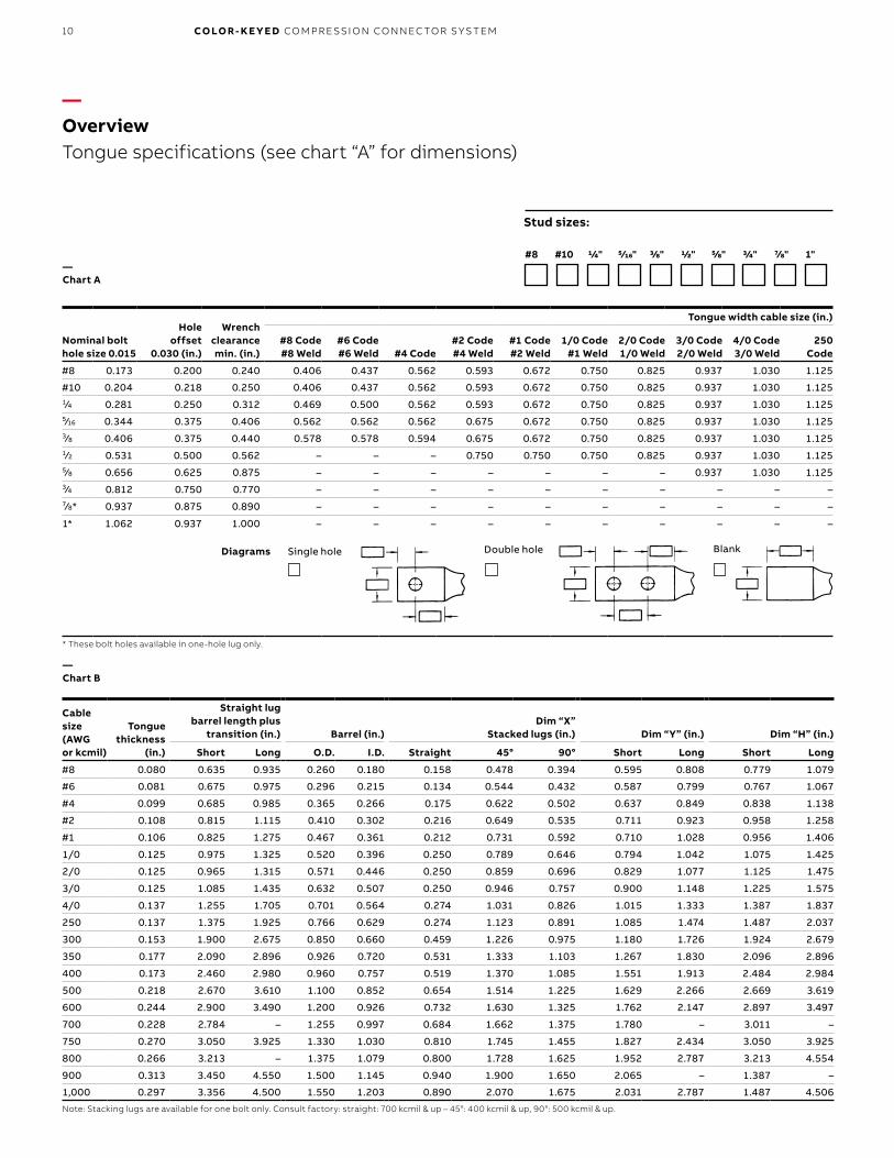
—OverviewTongue specifications (see chart “A” for dimensions)
Single Hole Double Hole Blank
Nominal bolt hole size 0.015
Holeoffset
0.030 (in.)
Wrenchclearance min. (in.)
Tongue width cable size (in.)
#8 Code #8 Weld
#6 Code#6 Weld #4 Code
#2 Code#4 Weld
#1 Code#2 Weld
1/0 Code#1 Weld
2/0 Code1/0 Weld
3/0 Code2/0 Weld
4/0 Code3/0 Weld
250 Code
#8 0.173 0.200 0.240 0.406 0.437 0.562 0.593 0.672 0.750 0.825 0.937 1.030 1.125
#10 0.204 0.218 0.250 0.406 0.437 0.562 0.593 0.672 0.750 0.825 0.937 1.030 1.1251⁄4 0.281 0.250 0.312 0.469 0.500 0.562 0.593 0.672 0.750 0.825 0.937 1.030 1.1255⁄16 0.344 0.375 0.406 0.562 0.562 0.562 0.675 0.672 0.750 0.825 0.937 1.030 1.1253⁄8 0.406 0.375 0.440 0.578 0.578 0.594 0.675 0.672 0.750 0.825 0.937 1.030 1.1251⁄2 0.531 0.500 0.562 – – – 0.750 0.750 0.750 0.825 0.937 1.030 1.1255⁄8 0.656 0.625 0.875 – – – – – – – 0.937 1.030 1.1253⁄4 0.812 0.750 0.770 – – – – – – – – – –7⁄8* 0.937 0.875 0.890 – – – – – – – – – –
1* 1.062 0.937 1.000 – – – – – – – – – –
* These bolt holes available in one-hole lug only.
Cablesize (AWG or kcmil)
Tonguethickness
(in.)
Straight lug barrel length plus
transition (in.) Barrel (in.)Dim “X”
Stacked lugs (in.) Dim “Y” (in.) Dim “H” (in.)
Short Long O.D. I.D. Straight 45° 90° Short Long Short Long
#8 0.080 0.635 0.935 0.260 0.180 0.158 0.478 0.394 0.595 0.808 0.779 1.079
#6 0.081 0.675 0.975 0.296 0.215 0.134 0.544 0.432 0.587 0.799 0.767 1.067
#4 0.099 0.685 0.985 0.365 0.266 0.175 0.622 0.502 0.637 0.849 0.838 1.138
#2 0.108 0.815 1.115 0.410 0.302 0.216 0.649 0.535 0.711 0.923 0.958 1.258
#1 0.106 0.825 1.275 0.467 0.361 0.212 0.731 0.592 0.710 1.028 0.956 1.406
1/0 0.125 0.975 1.325 0.520 0.396 0.250 0.789 0.646 0.794 1.042 1.075 1.425
2/0 0.125 0.965 1.315 0.571 0.446 0.250 0.859 0.696 0.829 1.077 1.125 1.475
3/0 0.125 1.085 1.435 0.632 0.507 0.250 0.946 0.757 0.900 1.148 1.225 1.575
4/0 0.137 1.255 1.705 0.701 0.564 0.274 1.031 0.826 1.015 1.333 1.387 1.837
250 0.137 1.375 1.925 0.766 0.629 0.274 1.123 0.891 1.085 1.474 1.487 2.037
300 0.153 1.900 2.675 0.850 0.660 0.459 1.226 0.975 1.180 1.726 1.924 2.679
350 0.177 2.090 2.896 0.926 0.720 0.531 1.333 1.103 1.267 1.830 2.096 2.896
400 0.173 2.460 2.980 0.960 0.757 0.519 1.370 1.085 1.551 1.913 2.484 2.984
500 0.218 2.670 3.610 1.100 0.852 0.654 1.514 1.225 1.629 2.266 2.669 3.619
600 0.244 2.900 3.490 1.200 0.926 0.732 1.630 1.325 1.762 2.147 2.897 3.497
700 0.228 2.784 – 1.255 0.997 0.684 1.662 1.375 1.780 – 3.011 –
750 0.270 3.050 3.925 1.330 1.030 0.810 1.745 1.455 1.827 2.434 3.050 3.925
800 0.266 3.213 – 1.375 1.079 0.800 1.728 1.625 1.952 2.787 3.213 4.554
900 0.313 3.450 4.550 1.500 1.145 0.940 1.900 1.650 2.065 – 1.387 –
1,000 0.297 3.356 4.500 1.550 1.203 0.890 2.070 1.675 2.031 2.787 1.487 4.506
Note: Stacking lugs are available for one bolt only. Consult factory: straight: 700 kcmil & up – 45°: 400 kcmil & up, 90°: 500 kcmil & up.
Single hole Double hole Blank
— Chart B
#8 #10 1/4" 5/16" 3/8" 1/2" 5/8" 3/4" 7/8" 1"
Stud sizes:
— Chart A
Diagrams

11OV ER V I E W
Straight stack 90° stack 45°45° stack 90°
T-top
0.125Typ
Formula 1
B-bottom XX
YX
H
Tongue width 0.030 code cable size (in.)
Bolt hole size
300 kcmil4/0 Weld
350 kcmil
400 kcmil
500 kcmil400 Weld
600 kcmil500 Weld 1325/24
700kcmil
750kcmil
800kcmil
900kcmil
1,000kcmil
#8 – – – – – – – – – – –
#10 – – – – – – – – – – –1⁄4 1.250 1.355 1.410 1.605 1.745 1.805 1.840 1.935 2.010 2.180 2.2655⁄16 1.250 1.355 1.410 1.605 1.745 1.805 1.840 1.935 2.010 2.180 2.2653⁄8 1.250 1.355 1.410 1.605 1.745 1.805 1.840 1.935 2.010 2.180 2.2651⁄2 1.250 1.355 1.410 1.605 1.745 1.805 1.840 1.935 2.010 2.180 2.2655⁄8 1.250 1.355 1.410 1.605 1.745 1.805 1.840 1.935 2.010 2.180 2.2653⁄4 1.250 1.355 1.410 1.605 1.745 1.805 1.840 1.935 2.010 2.180 2.2657⁄8* – – – 1.605 1.745 1.805 1.840 1.935 2.010 2.180 2.265
1* – – – – 1.745 1.805 1.840 1.935 2.010 2.180 2.265
* These bolt holes available in one-hole lug only.
— Chart C
Formula 1 = (0.125 + 2 (O.D.) + 0.037 – Tongue thickness)
Diagrams
B1 copy starts here
B2 copy starts here
B3 copy starts here
12 CO LO R- K E Y E D CO M PR E SSI O N CO N N EC TO R S Y S TEM
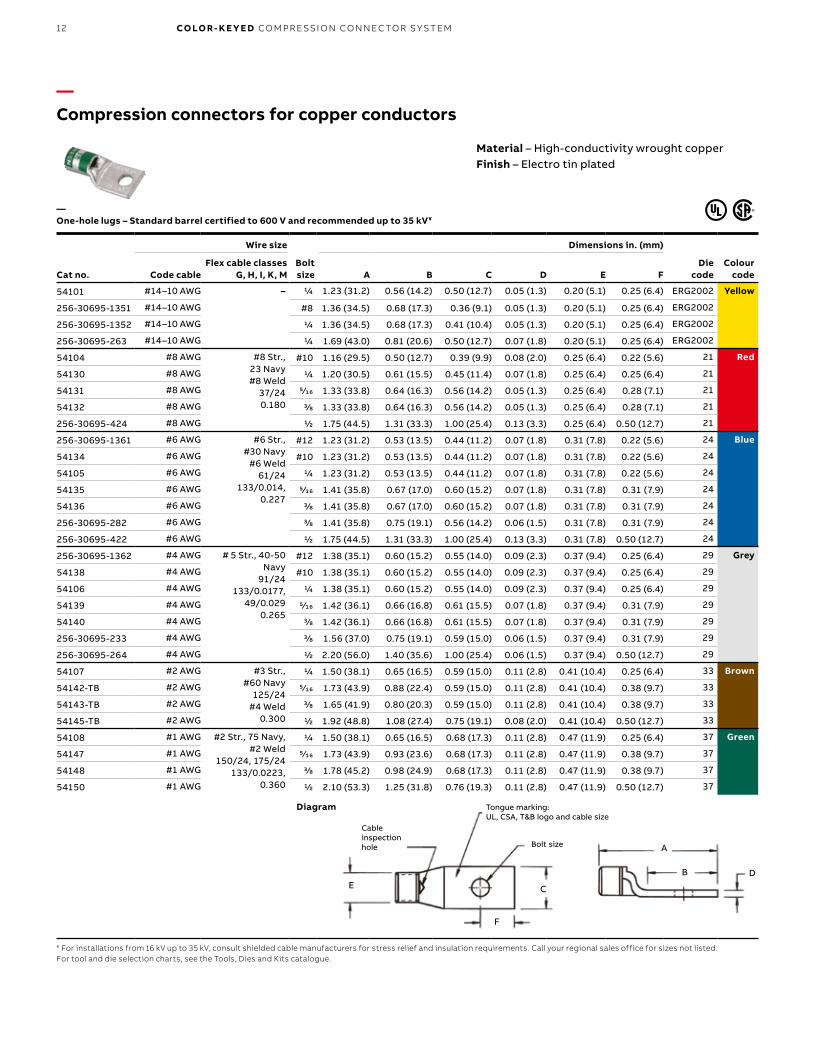
—Compression connectors for copper conductors
Material – High-conductivity wrought copperFinish – Electro tin plated
Cat no.
Wire size
Bolt size
Dimensions in. (mm)
Die code
Colour codeCode cable
Flex cable classes G, H, I, K, M A B C D E F
54101 #14–10 AWG – 1/4 1.23 (31.2) 0.56 (14.2) 0.50 (12.7) 0.05 (1.3) 0.20 (5.1) 0.25 (6.4) ERG2002 Yellow
256-30695-1351 #14–10 AWG #8 1.36 (34.5) 0.68 (17.3) 0.36 (9.1) 0.05 (1.3) 0.20 (5.1) 0.25 (6.4) ERG2002
256-30695-1352 #14–10 AWG 1/4 1.36 (34.5) 0.68 (17.3) 0.41 (10.4) 0.05 (1.3) 0.20 (5.1) 0.25 (6.4) ERG2002
256-30695-263 #14–10 AWG 1/4 1.69 (43.0) 0.81 (20.6) 0.50 (12.7) 0.07 (1.8) 0.20 (5.1) 0.25 (6.4) ERG2002
54104 #8 AWG #8 Str., 23 Navy#8 Weld
37/240.180
#10 1.16 (29.5) 0.50 (12.7) 0.39 (9.9) 0.08 (2.0) 0.25 (6.4) 0.22 (5.6) 21 Red
54130 #8 AWG 1/4 1.20 (30.5) 0.61 (15.5) 0.45 (11.4) 0.07 (1.8) 0.25 (6.4) 0.25 (6.4) 21
54131 #8 AWG 5⁄16 1.33 (33.8) 0.64 (16.3) 0.56 (14.2) 0.05 (1.3) 0.25 (6.4) 0.28 (7.1) 21
54132 #8 AWG 3/8 1.33 (33.8) 0.64 (16.3) 0.56 (14.2) 0.05 (1.3) 0.25 (6.4) 0.28 (7.1) 21
256-30695-424 #8 AWG 1/2 1.75 (44.5) 1.31 (33.3) 1.00 (25.4) 0.13 (3.3) 0.25 (6.4) 0.50 (12.7) 21
256-30695-1361 #6 AWG #6 Str., #30 Navy
#6 Weld61/24
133/0.014, 0.227
#12 1.23 (31.2) 0.53 (13.5) 0.44 (11.2) 0.07 (1.8) 0.31 (7.8) 0.22 (5.6) 24 Blue
54134 #6 AWG #10 1.23 (31.2) 0.53 (13.5) 0.44 (11.2) 0.07 (1.8) 0.31 (7.8) 0.22 (5.6) 24
54105 #6 AWG 1/4 1.23 (31.2) 0.53 (13.5) 0.44 (11.2) 0.07 (1.8) 0.31 (7.8) 0.22 (5.6) 24
54135 #6 AWG 5⁄16 1.41 (35.8) 0.67 (17.0) 0.60 (15.2) 0.07 (1.8) 0.31 (7.8) 0.31 (7.9) 24
54136 #6 AWG 3/8 1.41 (35.8) 0.67 (17.0) 0.60 (15.2) 0.07 (1.8) 0.31 (7.8) 0.31 (7.9) 24
256-30695-282 #6 AWG 3/8 1.41 (35.8) 0.75 (19.1) 0.56 (14.2) 0.06 (1.5) 0.31 (7.8) 0.31 (7.9) 24
256-30695-422 #6 AWG 1/2 1.75 (44.5) 1.31 (33.3) 1.00 (25.4) 0.13 (3.3) 0.31 (7.8) 0.50 (12.7) 24
256-30695-1362 #4 AWG # 5 Str., 40-50 Navy
91/24133/0.0177,
49/0.0290.265
#12 1.38 (35.1) 0.60 (15.2) 0.55 (14.0) 0.09 (2.3) 0.37 (9.4) 0.25 (6.4) 29 Grey
54138 #4 AWG #10 1.38 (35.1) 0.60 (15.2) 0.55 (14.0) 0.09 (2.3) 0.37 (9.4) 0.25 (6.4) 29
54106 #4 AWG 1/4 1.38 (35.1) 0.60 (15.2) 0.55 (14.0) 0.09 (2.3) 0.37 (9.4) 0.25 (6.4) 29
54139 #4 AWG 5⁄16 1.42 (36.1) 0.66 (16.8) 0.61 (15.5) 0.07 (1.8) 0.37 (9.4) 0.31 (7.9) 29
54140 #4 AWG 3/8 1.42 (36.1) 0.66 (16.8) 0.61 (15.5) 0.07 (1.8) 0.37 (9.4) 0.31 (7.9) 29
256-30695-233 #4 AWG 3/8 1.56 (37.0) 0.75 (19.1) 0.59 (15.0) 0.06 (1.5) 0.37 (9.4) 0.31 (7.9) 29
256-30695-264 #4 AWG 1/2 2.20 (56.0) 1.40 (35.6) 1.00 (25.4) 0.06 (1.5) 0.37 (9.4) 0.50 (12.7) 29
54107 #2 AWG #3 Str., #60 Navy
125/24#4 Weld
0.300
1/4 1.50 (38.1) 0.65 (16.5) 0.59 (15.0) 0.11 (2.8) 0.41 (10.4) 0.25 (6.4) 33 Brown
54142-TB #2 AWG 5⁄16 1.73 (43.9) 0.88 (22.4) 0.59 (15.0) 0.11 (2.8) 0.41 (10.4) 0.38 (9.7) 33
54143-TB #2 AWG 3/8 1.65 (41.9) 0.80 (20.3) 0.59 (15.0) 0.11 (2.8) 0.41 (10.4) 0.38 (9.7) 33
54145-TB #2 AWG 1/2 1.92 (48.8) 1.08 (27.4) 0.75 (19.1) 0.08 (2.0) 0.41 (10.4) 0.50 (12.7) 33
54108 #1 AWG #2 Str., 75 Navy, #2 Weld
150/24, 175/24133/0.0223,
0.360
1/4 1.50 (38.1) 0.65 (16.5) 0.68 (17.3) 0.11 (2.8) 0.47 (11.9) 0.25 (6.4) 37 Green
54147 #1 AWG 5⁄16 1.73 (43.9) 0.93 (23.6) 0.68 (17.3) 0.11 (2.8) 0.47 (11.9) 0.38 (9.7) 37
54148 #1 AWG 3/8 1.78 (45.2) 0.98 (24.9) 0.68 (17.3) 0.11 (2.8) 0.47 (11.9) 0.38 (9.7) 37
54150 #1 AWG 1/2 2.10 (53.3) 1.25 (31.8) 0.76 (19.3) 0.11 (2.8) 0.47 (11.9) 0.50 (12.7) 37
¥ For installations from 16 kV up to 35 kV, consult shielded cable manufacturers for stress relief and insulation requirements. Call your regional sales office for sizes not listed.For tool and die selection charts, see the Tools, Dies and Kits catalogue.
Diagram
—One-hole lugs – Standard barrel certified to 600 V and recommended up to 35 kV¥
E C
F
DB
A
Cableinspection hole Bolt size
Tongue marking: UL, CSA, T&B logo and cable size
13CO M PR E SSI O N CO N N EC TO R S FO R CO PPER CO N D U C TO R S
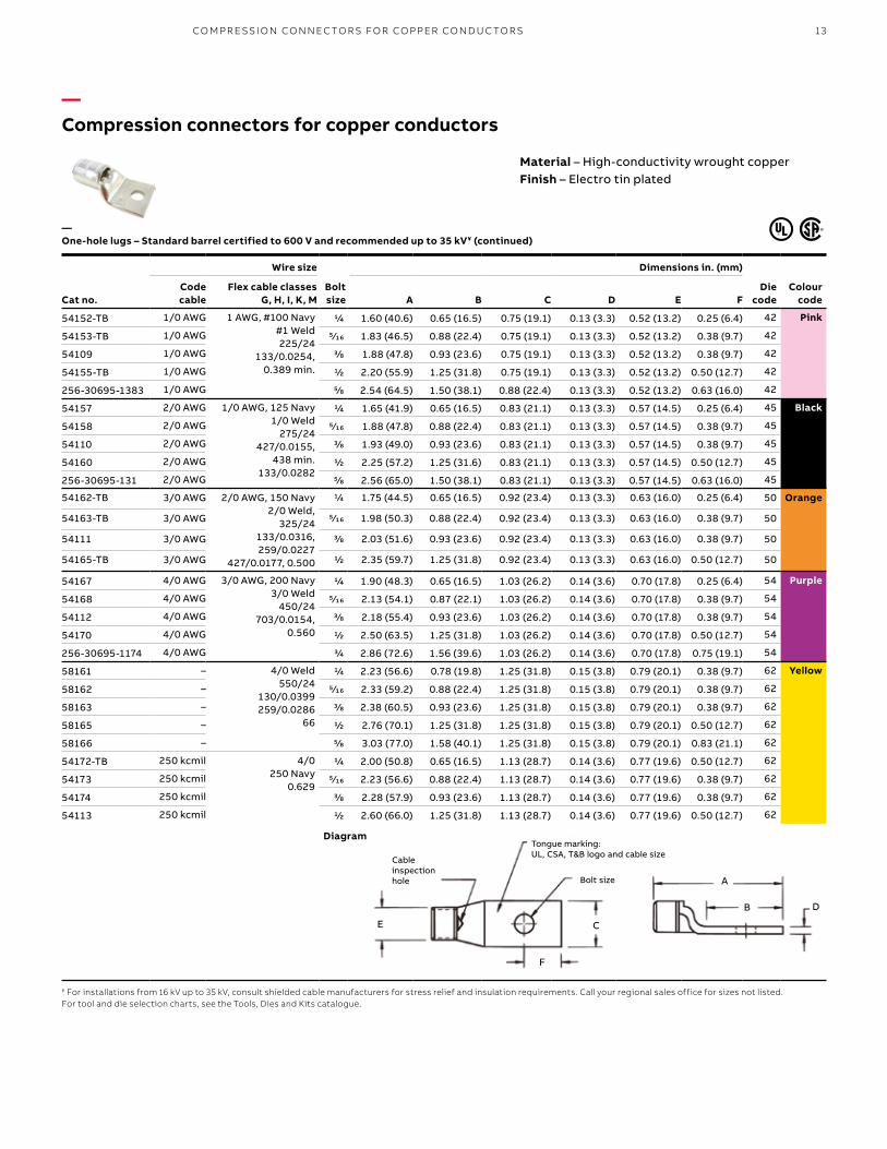
—Compression connectors for copper conductors
Cat no.
Wire size
Bolt size
Dimensions in. (mm)
Die code
Colour code
Code cable
Flex cable classes G, H, I, K, M A B C D E F
54152-TB 1/0 AWG 1 AWG, #100 Navy#1 Weld225/24
133/0.0254, 0.389 min.
1/4 1.60 (40.6) 0.65 (16.5) 0.75 (19.1) 0.13 (3.3) 0.52 (13.2) 0.25 (6.4) 42 Pink
54153-TB 1/0 AWG 5⁄16 1.83 (46.5) 0.88 (22.4) 0.75 (19.1) 0.13 (3.3) 0.52 (13.2) 0.38 (9.7) 42
54109 1/0 AWG 3/8 1.88 (47.8) 0.93 (23.6) 0.75 (19.1) 0.13 (3.3) 0.52 (13.2) 0.38 (9.7) 42
54155-TB 1/0 AWG 1/2 2.20 (55.9) 1.25 (31.8) 0.75 (19.1) 0.13 (3.3) 0.52 (13.2) 0.50 (12.7) 42
256-30695-1383 1/0 AWG 5/8 2.54 (64.5) 1.50 (38.1) 0.88 (22.4) 0.13 (3.3) 0.52 (13.2) 0.63 (16.0) 42
54157 2/0 AWG 1/0 AWG, 125 Navy1/0 Weld
275/24427/0.0155,
438 min.133/0.0282
1/4 1.65 (41.9) 0.65 (16.5) 0.83 (21.1) 0.13 (3.3) 0.57 (14.5) 0.25 (6.4) 45 Black
54158 2/0 AWG 5⁄16 1.88 (47.8) 0.88 (22.4) 0.83 (21.1) 0.13 (3.3) 0.57 (14.5) 0.38 (9.7) 45
54110 2/0 AWG 3/8 1.93 (49.0) 0.93 (23.6) 0.83 (21.1) 0.13 (3.3) 0.57 (14.5) 0.38 (9.7) 45
54160 2/0 AWG 1/2 2.25 (57.2) 1.25 (31.6) 0.83 (21.1) 0.13 (3.3) 0.57 (14.5) 0.50 (12.7) 45
256-30695-131 2/0 AWG 5/8 2.56 (65.0) 1.50 (38.1) 0.83 (21.1) 0.13 (3.3) 0.57 (14.5) 0.63 (16.0) 45
54162-TB 3/0 AWG 2/0 AWG, 150 Navy2/0 Weld,
325/24133/0.0316, 259/0.0227
427/0.0177, 0.500
1/4 1.75 (44.5) 0.65 (16.5) 0.92 (23.4) 0.13 (3.3) 0.63 (16.0) 0.25 (6.4) 50 Orange
54163-TB 3/0 AWG 5⁄16 1.98 (50.3) 0.88 (22.4) 0.92 (23.4) 0.13 (3.3) 0.63 (16.0) 0.38 (9.7) 50
54111 3/0 AWG 3/8 2.03 (51.6) 0.93 (23.6) 0.92 (23.4) 0.13 (3.3) 0.63 (16.0) 0.38 (9.7) 50
54165-TB 3/0 AWG 1/2 2.35 (59.7) 1.25 (31.8) 0.92 (23.4) 0.13 (3.3) 0.63 (16.0) 0.50 (12.7) 50
54167 4/0 AWG 3/0 AWG, 200 Navy3/0 Weld
450/24703/0.0154,
0.560
1/4 1.90 (48.3) 0.65 (16.5) 1.03 (26.2) 0.14 (3.6) 0.70 (17.8) 0.25 (6.4) 54 Purple
54168 4/0 AWG 5⁄16 2.13 (54.1) 0.87 (22.1) 1.03 (26.2) 0.14 (3.6) 0.70 (17.8) 0.38 (9.7) 54
54112 4/0 AWG 3/8 2.18 (55.4) 0.93 (23.6) 1.03 (26.2) 0.14 (3.6) 0.70 (17.8) 0.38 (9.7) 54
54170 4/0 AWG 1/2 2.50 (63.5) 1.25 (31.8) 1.03 (26.2) 0.14 (3.6) 0.70 (17.8) 0.50 (12.7) 54
256-30695-1174 4/0 AWG 3/4 2.86 (72.6) 1.56 (39.6) 1.03 (26.2) 0.14 (3.6) 0.70 (17.8) 0.75 (19.1) 54
58161 – 4/0 Weld550/24
130/0.0399259/0.0286
66
1/4 2.23 (56.6) 0.78 (19.8) 1.25 (31.8) 0.15 (3.8) 0.79 (20.1) 0.38 (9.7) 62 Yellow
58162 – 5⁄16 2.33 (59.2) 0.88 (22.4) 1.25 (31.8) 0.15 (3.8) 0.79 (20.1) 0.38 (9.7) 62
58163 – 3/8 2.38 (60.5) 0.93 (23.6) 1.25 (31.8) 0.15 (3.8) 0.79 (20.1) 0.38 (9.7) 62
58165 – 1/2 2.76 (70.1) 1.25 (31.8) 1.25 (31.8) 0.15 (3.8) 0.79 (20.1) 0.50 (12.7) 62
58166 – 5/8 3.03 (77.0) 1.58 (40.1) 1.25 (31.8) 0.15 (3.8) 0.79 (20.1) 0.83 (21.1) 62
54172-TB 250 kcmil 4/0250 Navy
0.629
1/4 2.00 (50.8) 0.65 (16.5) 1.13 (28.7) 0.14 (3.6) 0.77 (19.6) 0.50 (12.7) 62
54173 250 kcmil 5⁄16 2.23 (56.6) 0.88 (22.4) 1.13 (28.7) 0.14 (3.6) 0.77 (19.6) 0.38 (9.7) 62
54174 250 kcmil 3/8 2.28 (57.9) 0.93 (23.6) 1.13 (28.7) 0.14 (3.6) 0.77 (19.6) 0.38 (9.7) 62
54113 250 kcmil 1/2 2.60 (66.0) 1.25 (31.8) 1.13 (28.7) 0.14 (3.6) 0.77 (19.6) 0.50 (12.7) 62
—One-hole lugs – Standard barrel certified to 600 V and recommended up to 35 kV¥ (continued)
¥ For installations from 16 kV up to 35 kV, consult shielded cable manufacturers for stress relief and insulation requirements. Call your regional sales office for sizes not listed.For tool and die selection charts, see the Tools, Dies and Kits catalogue.
Diagram
Material – High-conductivity wrought copperFinish – Electro tin plated
E C
F
DB
A
Cableinspection hole Bolt size
Tongue marking: UL, CSA, T&B logo and cable size

B1 copy starts here
B2 copy starts here
B3 copy starts here
14 CO LO R- K E Y E D CO M PR E SSI O N CO N N EC TO R S Y S TEM
—Compression connectors for copper conductors
¥ For installations from 16 kV up to 35 kV, consult shielded cable manufacturers for stress relief and insulation requirements. Call your regional sales office for sizes not listed.For tool and die selection charts, see the Tools, Dies and Kits catalogue.
Diagram
—One-hole lugs – Standard barrel certified to 600 V and recommended up to 35 kV¥ (continued)
Cat no.
Wire size
Bolt size
Dimensions in. (mm)
Die code
Colour code
Code cable
Flex cable classes G, H, I, K, M A B C D E F
58168 – 250 Weld650/24 = 262 kcmil
259/0.0311, 703/0.0189
1/2 2.70 (68.6) 1.25 (31.8) 1.25 (31.8) 0.15 (3.8) 0.85 (21.6) 0.50 (12.7) 66 White
54178 300 kcmil 250 kcmil300 Navy
0.660
5⁄16 2.33 (59.2) 0.88 (22.4) 1.25 (31.8) 0.15 (3.8) 0.85 (21.6) 0.38 (9.7) 66
54179 3/8 2.43 (61.7) 0.93 (23.6) 1.25 (31.8) 0.15 (3.8) 0.85 (21.6) 0.38 (9.7) 66
54114 1/2 2.70 (68.6) 1.25 (31.8) 1.25 (31.8) 0.15 (3.8) 0.85 (21.6) 0.50 (12.7) 66
54181 5/8 3.03 (77.0) 1.58 (40.1) 1.25 (31.8) 0.15 (3.8) 0.85 (21.6) 0.75 (19.1) 66
58171 – 300 Weld, 259/0.034427/0.0265, 889/0.0183
775/24 = 313 kcmil, 0.719
1/2 2.85 (72.4) 1.25 (31.8) 1.36 (34.5) 0.18 (4.6) 0.93 (23.6) 0.50 (12.7) 71 Red
256-30695-112 350 kcmil 350 Navy0.719
3/8 2.90 (73.7) 1.25 (31.8) 1.36 (34.5) 0.18 (4.6) 0.93 (23.6) 0.50 (12.7) 71
54115 350 kcmil 1/2 2.85 (72.4) 1.25 (31.8) 1.36 (34.5) 0.18 (4.6) 0.93 (23.6) 0.50 (12.7) 71
54183 350 kcmil 5/8 3.21 (81.5) 1.28 (32.5) 1.36 (34.5) 0.18 (4.6) 0.93 (23.6) 0.75 (19.1) 71
58174 – 350 Weld, 259/0.0368427/0.0285889/0.0201
1/2 3.35 (85.1) 1.25 (31.8) 1.61 (40.9) 0.22 (5.6) 1.09 (27.7) 0.50 (12.7) 76 Blue
54116 400 kcmil 300 kcmil,400 Navy, 0.757
1/2 3.20 (81.3) 1.25 (31.8) 1.41 (35.8) 0.17 (4.3) 0.96 (24.4) 0.50 (12.7) 76
54185 400 kcmil 5/8 3.53 (89.7) 1.58 (40.1) 1.41 (35.8) 0.17 (4.3) 0.96 (24.4) 0.75 (19.1) 76
58177 – 400 Weld925/24 = 373 kcmil
259/0.0393 or427/0.0306, 0.799
1/2 3.31 (84.1) 1.25 (31.8) 1.61 (40.9) 0.22 (5.6) 1.04 (26.4) 0.50 (12.7) 80 –
256-30695-1403 – 3/8 3.31 (84.1) 1.31 (33.3) 1.61 (40.9) 0.22 (5.6) 1.04 (26.4) 0.63 (16.0) 80
256-30695-339 500 kcmil 925/24500 Navy
0.850
3/8 3.10 (78.7) 1.00 (25.4) 1.61 (40.9) 0.22 (5.6) 1.10 (28.0) 0.38 (9.7) 87 Brown
54118 500 kcmil 1/2 3.30 (83.8) 1.25 (31.8) 1.61 (40.9) 0.22 (5.6) 1.10 (27.9) 0.50 (12.7) 87
54187 500 kcmil 5/8 3.63 (92.2) 1.58 (40.1) 1.61 (40.9) 0.22 (5.6) 1.10 (27.9) 0.63 (16.0) 87
58180 – 1100/24 = 444 kcmil500 Weld, 259/0.0417
427/0.0325, 703/0.0253
5/8 3.79 (96.3) 1.58 (40.1) 1.75 (44.5) 0.24 (6.1) 1.20 (30.5) 0.63 (16.0) 94 Green
256-30695-1370 600 kcmil 0.956 1/2 3.65 (92.7) 1.44 (36.6) 1.75 (44.5) 0.24 (6.1) 1.20 (30.5) 0.48 (12.2) 94
54120 600 kcmil 5/8 3.79 (96.3) 1.58 (40.1) 1.75 (44.5) 0.24 (6.1) 1.20 (30.5) 0.63 (16.0) 94
Material – High-conductivity wrought copperFinish – Electro tin plated
E C
F
DB
A
Cableinspection hole Bolt size
Tongue marking: UL, CSA, T&B logo and cable size

15
—Compression connectors for copper conductors
¥ For installations from 16 kV up to 35 kV, consult shielded cable manufacturers for stress relief and insulation requirements. Call your regional sales office for sizes not listed.For tool and die selection charts, see the Tools, Dies and Kits catalogue.
Diagram
—One-hole lugs – Standard barrel certified to 600 V and recommended up to 35 kV¥ (continued)
Cat no.
Wire size
Bolt size
Dimensions in. (mm)
Die code
Colour codeCode cable
Flex cable classes G, H, I, K, M A B C D E F
54122-TB 700 kcmil – 5/8 3.68 (93.5) 1.58 (40.1) 1.84 (46.7) 0.23 (5.8) 1.26 (32.0) 0.63 (16.0) 99 Pink
256-30695-1404 – 1325/24 = 500/535 kcmil
427/0.0342, 0.968
3/8 3.29 (83.6) 1.29 (32.8) 1.81 (46.0) 0.28 (7.1) 1.25 (31.8) 0.66 (16.8) 99
256-30695-1405 – 1/2 3.29 (83.6) 1.29 (32.8) 1.81 (46.0) 0.28 (7.1) 1.25 (31.8) 0.66 (16.8) 99
256-30695-840 – 1/2 4.00 (101.6) 1.69 (42.9) 1.81 (46.0) 0.28 (7.1) 1.25 (31.8) 0.48 (12.2) 99
58182 – 5/8 3.83 (97.3) 1.58 (40.1) 1.81 (46.0) 0.28 (7.1) 1.25 (31.8) 0.63 (16.0) 99
256-30695-193 – 1.060 1/2 4.00 (101.6) 1,69 (42.9) 1.94 (49.3) 0.27 (6.9) 1.33 (33.8) 0.48 (12.2) 106 Black
54123-TB 750 kcmil 1.060 5/8 3.87 (98.3) 1.58 (40.1) 1.94 (49.3) 0.27 (6.9) 1.33 (33.8) 0.63 (16.0) 106
58184 – 1600/24 = 646 kcmil 5/8 3.80 (96.5) 1.58 (40.1) 1.94 (49.3) 0.27 (6.9) 1.33 (33.8) 0.63 (16.0) 106
54124-TB 800 kcmil 800 Navy, 1.109 5/8 4.04 (102.6) 1.58 (40.1) 2.01 (51.1) 0.27 (6.9) 1.38 (35.1) 0.63 (16.0) 107 Orange
256-30695-843 900 kcmil 1925/24 = 750/777 kcmil, 1.187
1/2 4.31 (109.5) 1.81 (46.0) 2.17 (55.1) 0.31 (7.9) 1.50 (38.1) 0.88 (22.4) 115 Yellow
54126 900 kcmil 5/8 4.15 (105.4) 1.58 (40.1) 2.17 (55.1) 0.31 (7.9) 1.50 (38.1) 0.63 (16.0) 115
54128 1,000 kcmil 1,000 Navy, 1.253 5/8 4.09 (103.9) 1.58 (40.1) 2.27 (57.7) 0.30 (7.6) 1.55 (39.4) 0.63 (16.0) 125 –
Material – High-conductivity wrought copperFinish – Electro tin plated
E C
F
DB
Bolt size A
Cableinspection hole
Tongue marking: UL, CSA, T&B logo and cable size
CO M PR E SSI O N CO N N EC TO R S FO R CO PPER CO N D U C TO R S
B1 copy starts here
B2 copy starts here
B3 copy starts here
16 CO LO R- K E Y E D CO M PR E SSI O N CO N N EC TO R S Y S TEM
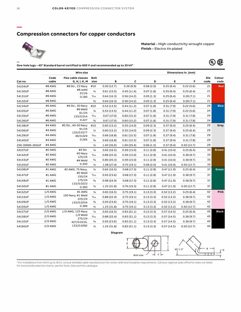
—Compression connectors for copper conductors
Material – High-conductivity wrought copperFinish – Electro tin plated
Cat no.
Wire size
Bolt size
Dimensions in. (mm)
Die code
Colour code
Code cable
Flex cable classes G, H, I, K, M B C D E F
54104UF #8 AWG #8 Str., 23 Navy#8 weld
37/240.180
#10 0.50 (12.7) 0.39 (9.9) 0.08 (2.0) 0.25 (6.4) 0.22 (5.6) 21 Red
54130UF #8 AWG 1/4 0.61 (15.5) 0.45 (11.4) 0.07 (1.8) 0.25 (6.4) 0.25 (6.4) 21
54131UF #8 AWG 5⁄16 0.64 (16.3) 0.56 (14.2) 0.05 (1.3) 0.25 (6.4) 0.28 (7.1) 21
54132UF #8 AWG 3/8 0.64 (16.3) 0.56 (14.2) 0.05 (1.3) 0.25 (6.4) 0.28 (7.1) 21
54134UF #6 AWG #6 Str., 30 Navy#6 Weld
61/24133/0.014
0.227
#10 0.53 (13.5) 0.44 (11.2) 0.07 (1.8) 0.31 (7.9) 0.22 (5.6) 24 Blue
54105UF #6 AWG 1/4 0.53 (13.5) 0.44 (11.2) 0.07 (1.8) 0.31 (7.9) 0.22 (5.6) 24
54135UF #6 AWG 5⁄16 0.67 (17.0) 0.60 (15.2) 0.07 (1.8) 0.31 (7.9) 0.31 (7.8) 24
54136UF #6 AWG 3/8 0.67 (17.0) 0.60 (15.2) 0.07 (1.8) 0.31 (7.9) 0.31 (7.8) 24
54138UF #4 AWG #5 Str., 40-50 Navy91/24
133/0.017749/0.029
0.265
#10 0.60 (15.2) 0.55 (14.0) 0.09 (2.3) 0.37 (9.4) 0.25 (6.4) 29 Grey
54106UF #4 AWG 1/4 0.60 (15.2) 0.55 (14.0) 0.09 (2.3) 0.37 (9.4) 0.25 (6.4) 29
54139UF #4 AWG 5⁄16 0.66 (16.8) 0.61 (15.5) 0.07 (1.8) 0.37 (9.4) 0.31 (7.8) 29
54140UF #4 AWG 3/8 0.66 (16.8) 0.61 (15.5) 0.07 (1.8) 0.37 (9.4) 0.31 (7.8) 29
256-30695-264UF #4 AWG 1/2 1.40 (35.6) 1.00 (25.4) 0.06 (1.5) 0.37 (9.4) 0.50 (12.7) 29
54107UF #2 AWG #3 Str.60 Navy125/24
#4 Weld0.300
1/4 0.65 (16.5) 0.59 (15.0) 0.11 (2.8) 0.41 (10.4) 0.25 (6.4) 33 Brown
54142UF #2 AWG 5⁄16 0.88 (22.4) 0.59 (15.0) 0.11 (2.8) 0.41 (10.4) 0.38 (9.7) 33
54143UF #2 AWG 3/8 0.80 (20.3) 0.59 (15.0) 0.11 (2.8) 0.41 (10.4) 0.38 (9.7) 33
54145UF #2 AWG 1/2 1.08 (27.4) 0.75 (19.1) 0.08 (2.0) 0.41 (10.4) 0.50 (12.7) 33
54108UF #1 AWG #2 AWG, 75 Navy, #2 Weld150/24175/24
133/0.02230.360
1/4 0.65 (16.5) 0.68 (17.3) 0.11 (2.8) 0.47 (11.9) 0.25 (6.4) 37 Green
54147UF #1 AWG 5⁄16 0.93 (23.6) 0.68 (17.3) 0.11 (2.8) 0.47 (11.9) 0.38 (9.7) 37
54148UF #1 AWG 3/8 0.98 (24.9) 0.68 (17.3) 0.11 (2.8) 0.47 (11.9) 0.38 (9.7) 37
54150UF #1 AWG 1/2 1.25 (31.8) 0.76 (19.3) 0.11 (2.8) 0.47 (11.9) 0.50 (12.7) 37
54152UF 1/0 AWG #1 AWG100 Navy, #1 Weld
225/24133/0.0254
0.389
1/4 0.65 (16.5) 0.75 (19.1) 0.13 (3.3) 0.52 (13.2) 0.25 (6.4) 42 Pink
54153UF 1/0 AWG 5⁄16 0.88 (22.4) 0.75 (19.1) 0.13 (3.3) 0.52 (13.2) 0.38 (9.7) 42
54109UF 1/0 AWG 3/8 0.93 (23.6) 0.75 (19.1) 0.13 (3.3) 0.52 (13.2) 0.38 (9.7) 42
54155UF 1/0 AWG 1/2 1.25 (31.8) 0.75 (19.1) 0.13 (3.3) 0.52 (13.2) 0.50 (12.7) 42
54157UF 2/0 AWG 1/0 AWG, 125 Navy1/0 Weld
275/24427/0.0155, 133/0.0282
1/4 0.65 (16.5) 0.83 (21.1) 0.13 (3.3) 0.57 (14.5) 0.25 (6.4) 45 Black
54158UF 2/0 AWG 5⁄16 0.88 (22.4) 0.83 (21.1) 0.13 (3.3) 0.57 (14.5) 0.38 (9.7) 45
54110UF 2/0 AWG 3/8 0.93 (23.6) 0.83 (21.1) 0.13 (3.3) 0.57 (14.5) 0.38 (9.7) 45
54160UF 2/0 AWG 1/2 1.25 (31.8) 0.83 (21.1) 0.13 (3.3) 0.57 (14.5) 0.50 (12.7) 45
¥ For installations from 16 kV up to 35 kV, consult shielded cable manufacturers for stress relief and insulation requirements. Call your regional sales office for sizes not listed.For tool and die selection charts, see the Tools, Dies and Kits catalogue.
—One-hole lugs – 45° Standard barrel certified to 600 V and recommended up to 35 kV¥
Diagram
E C
F
DB45° ± 3°
Bolt size
Diagrams
17
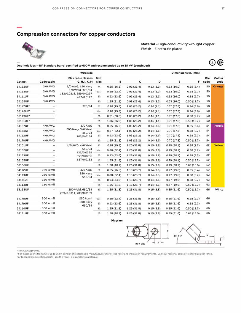
—Compression connectors for copper conductors
Cat no.
Wire size
Bolt size
Dimensions in. (mm)
Die code
Colour codeCode cable
Flex cable classes G, H, I, K, M B C D E F
54162UF 3/0 AWG 2/0 AWG, 150 Navy2/0 Weld, 325/24
133/0.0316, 259/0.0227427/0.0177
1/4 0.65 (16.5) 0.92 (23.4) 0.13 (3.3) 0.63 (16.0) 0.25 (6.4) 50 Orange
54163UF 3/0 AWG 5⁄16 0.88 (22.4) 0.92 (23.4) 0.13 (3.3) 0.63 (16.0) 0.38 (9.7) 50
54111UF 3/0 AWG 3/8 0.93 (23.6) 0.92 (23.4) 0.13 (3.3) 0.63 (16.0) 0.38 (9.7) 50
54165UF 3/0 AWG 1/2 1.25 (31.8) 0.92 (23.4) 0.13 (3.3) 0.63 (16.0) 0.50 (12.7) 50
58147UF* – 375/24 1/4 0.78 (19.8) 1.03 (26.2) 0.16 (4.1) 0.70 (17.8) 0.34 (8.6) 50
58148UF* – 5⁄16 0.78 (19.8) 1.03 (26.2) 0.16 (4.1) 0.70 (17.8) 0.34 (8.6) 50
58149UF* – 3/8 0.81 (20.6) 1.03 (26.2) 0.16 (4.1) 0.70 (17.8) 0.38 (9.7) 50
58151UF* – 1/2 1.06 (26.9) 1.03 (26.2) 0.16 (4.1) 0.70 (17.8) 0.50 (12.7) 50
54167UF 4/0 AWG 3/0 AWG200 Navy, 3/0 Weld
450/24703/0.0154
1/4 0.65 (16.5) 1.03 (26.2) 0.14 (3.6) 0.70 (17.8) 0.25 (6.4) 54 Purple
54168UF 4/0 AWG 5⁄16 0.87 (22.1) 1.03 (26.2) 0.14 (3.6) 0.70 (17.8) 0.38 (9.7) 54
54112UF 4/0 AWG 3/8 0.93 (23.6) 1.03 (26.2) 0.14 (3.6) 0.70 (17.8) 0.38 (9.7) 54
54170UF 4/0 AWG 1/2 1.25 (31.8) 1.03 (26.2) 0.14 (3.6) 0.70 (17.8) 0.50 (12.7) 54
58161UF – 4/0 AWG, 4/0 Weld550/24
133/0.0399259/0.0286637/0.0183
1/4 0.78 (19.8) 1.25 (31.8) 0.15 (3.8) 0.79 (20.1) 0.38 (9.7) 62 Yellow
58162UF – 5⁄16 0.88 (22.4) 1.25 (31.8) 0.15 (3.8) 0.79 (20.1) 0.38 (9.7) 62
58163UF – 3/8 0.93 (23.6) 1.25 (31.8) 0.15 (3.8) 0.79 (20.1) 0.38 (9.7) 62
58165UF – 1/2 1.25 (31.8) 1.25 (31.8) 0.15 (3.8) 0.79 (20.1) 0.50 (12.7) 62
58166UF – 5/8 1.58 (40.1) 1.25 (31.8) 0.15 (3.8) 0.79 (20.1) 0.63 (16.0) 62
54172UF 250 kcmil 4/0 AWG250 Navy
550/24
1/4 0.65 (16.5) 1.13 (28.7) 0.14 (3.6) 0.77 (19.6) 0.25 (6.4) 62
54173UF 250 kcmil 5⁄16 0.88 (22.4) 1.13 (28.7) 0.14 (3.6) 0.77 (19.6) 0.38 (9.7) 62
54174UF 250 kcmil 3/8 0.93 (23.6) 1.13 (28.7) 0.14 (3.6) 0.77 (19.6) 0.38 (9.7) 62
54113UF 250 kcmil 1/2 1.25 (31.8) 1.13 (28.7) 0.14 (3.6) 0.77 (19.6) 0.50 (12.7) 62
58168UF – 250 Weld, 650/24259/0.0311, 703/0.0189
1/2 1.25 (31.8) 1.25 (31.8) 0.15 (3.8) 0.85 (21.6) 0.50 (12.7) 66 White
54178UF 300 kcmil 250 kcmil300 Navy
650/24
5⁄16 0.88 (22.4) 1.25 (31.8) 0.15 (3.8) 0.85 (21.6) 0.38 (9.7) 66
54179UF 300 kcmil 3/8 0.93 (23.6) 1.25 (31.8) 0.15 (3.8) 0.85 (21.6) 0.38 (9.7) 66
54114UF 300 kcmil 1/2 1.25 (31.8) 1.25 (31.8) 0.15 (3.8) 0.85 (21.6) 0.50 (12.7) 66
54181UF 300 kcmil 5/8 1.58 (40.1) 1.25 (31.8) 0.15 (3.8) 0.85 (21.6) 0.63 (16.0) 66
—One-hole lugs – 45° Standard barrel certified to 600 V and recommended up to 35 kV¥ (continued)
* Not CSA approved.¥ For installations from 16 kV up to 35 kV, consult shielded cable manufacturers for stress relief and insulation requirements. Call your regional sales office for sizes not listed.For tool and die selection charts, see the Tools, Dies and Kits catalogue.
Diagram
Material – High-conductivity wrought copperFinish – Electro tin plated
C
F
DB45° ± 3°
Bolt size
E
CO M PR E SSI O N CO N N EC TO R S FO R CO PPER CO N D U C TO R S

B1 copy starts here
B2 copy starts here
B3 copy starts here
18 CO LO R- K E Y E D CO M PR E SSI O N CO N N EC TO R S Y S TEM
—Compression connectors for copper conductors
Cat no.
Wire size
Bolt size
Dimensions in. (mm)
Die code
Colour codeCode cable
Flex cable classes G, H, I, K, M B C D E F
58171UF – 300 kcmil, 300 Weld259/0.034, 427/0.0265
889/0.0183775/24 = 313 kcmil
1/2 1.25 (31.8) 1.36 (34.5) 0.18 (4.6) 0.93 (23.6) 0.50 (12.7) 71 Red
256-30695-112UF 350 kcmil 650/24350 Navy262 kcmil
3/8 1.25 (31.8) 1.36 (34.5) 0.18 (4.6) 0.93 (23.6) 0.50 (12.7) 71
54115UF 350 kcmil 1/2 1.25 (31.8) 1.36 (34.5) 0.18 (4.6) 0.93 (23.6) 0.50 (12.7) 71
54183UF 350 kcmil 5/8 1.58 (40.1) 1.36 (34.5) 0.18 (4.6) 0.93 (23.6) 0.63 (16.0) 71
58174UF – 350 Weld259/0.0368, 427/0.0285703/0.0224, 889/0.0201
1/2 1.25 (31.8) 1.61 (40.9) 0.22 (5.6) 1.09 (27.7) 0.50 (12.7) 76 Blue
54116UF 400 kcmil 300 kcmil, 400 Navy775/24, 313 kmcil
1/2 1.25 (31.8) 1.41 (35.8) 0.17 (4.3) 0.96 (24.4) 0.50 (12.7) 76
54185UF 400 kcmil 5/8 1.58 (40.1) 1.41 (35.8) 0.17 (4.3) 0.96 (24.4) 0.63 (16.0) 76
256-30695-1403UF – 350 kcmil, 400 Weld925/24 = 373 kcmil
3/8 1.31 (28.7) 1.61 (40.9) 0.22 (5.6) 1.04 (26.4) 0.63 (16.0) 80 –
58177UF – 1/2 1.25 (31.8) 1.61 (40.9) 0.22 (5.6) 1.04 (26.4) 0.50 (12.7) 80
54118UF 500 kcmil 925/24500 Navy400 kcmil
1/2 1.25 (31.8) 1.61 (40.9) 0.22 (5.6) 1.10 (27.9) 0.50 (12.7) 87 Brown
58187UF 500 kcmil 5/8 1.58 (40.1) 1.61 (40.9) 0.22 (5.6) 1.10 (27.9) 0.63 (16.0) 87
58180UF – 1,100/24 = 444 kcmil500 Weld, 259/0.0417
427/0.0325, 703/0.0253
5/8 1.58 (40.1) 1.75 (44.5) 0.24 (6.1) 1.20 (30.5) 0.50 (12.7) 94 Green
58120UF 600 kcmil 1,110/24 = 444 kcmil 5/8 1.58 (40.1) 1.75 (44.5) 0.24 (6.1) 1.20 (30.5) 0.50 (12.7) 94
54122UF 700 kcmil 1325/24 = 500 kcmil 5/8 1.58 (40.1) 1.84 (46.7) 0.23 (5.8) 1.26 (32.0) 0.50 (12.7) 99 Pink
256-30695-840UF – 1,325/24 = 535 kcmil427/0.0342
1/2 1.69 (42.9) 1.81 (46.0) 0.28 (7.1) 1.25 (31.8) 0.81 (20.6) 99
58182UF – 5/8 1.58 (40.1) 1.81 (46.0) 0.28 (7.1) 1.25 (31.8) 0.63 (16.0) 99
54123UF 750 kcmil 1,325/24 = 535 kcmil 5/8 1.58 (40.1) 1.94 (49.3) 0.27 (6.9) 1.33 (33.8) 0.63 (16.0) 106 Black
58184UF – 1,600/24 = 646 kcmil 5/8 1.58 (40.1) 1.94 (49.3) 0.27 (6.9) 1.33 (33.8) 0.63 (16.0) 106
54124UF 800 kcmil 800 Navy 5/8 1.58 (40.1) 2.01 (51.1) 0.27 (6.9) 1.38 (35.1) 0.63 (16.0) 107 Orange
54126UF 900 kcmil 1,925/24 = 777 kcmil 5/8 1.58 (40.1) 2.17 (55.1) 0.31 (7.9) 1.50 (38.1) 0.63 (16.0) 115 Yellow
54128UF 1,000 kcmil 1,000 Navy 5/8 1.58 (40.1) 2.27 (57.7) 0.30 (7.6) 1.55 (39.4) 0.63 (16.0) 125 –
¥ For installations from 16 kV up to 35 kV, consult shielded cable manufacturers for stress relief and insulation requirements. Call your regional sales office for sizes not listed.For tool and die selection charts, see the Tools, Dies and Kits catalogue.
—One-hole lugs – 45° Standard barrel certified to 600 V and recommended up to 35 kV¥ (continued)
Diagram
Material – High-conductivity wrought copperFinish – Electro tin plated
E C
F
DB45° ± 3°
Bolt size
19
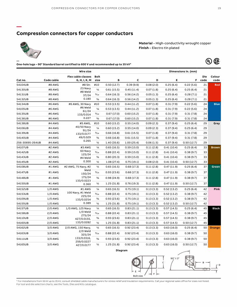
—Compression connectors for copper conductors
Material – High-conductivity wrought copperFinish – Electro tin plated
Cat no.
Wire size
Bolt size
Dimensions in. (mm)
Die code
Colour codeCode cable
Flex cable classes G, H, I, K, M B C D E F
54104UB #8 AWG #8 Str.23 Navy#8 Weld
37/240.180
#10 0.50 (12.7) 0.39 (9.9) 0.08 (2.0) 0.25 (6.4) 0.22 (5.6) 21 Red
54130UB #8 AWG 1/4 0.61 (15.5) 0.45 (11.4) 0.07 (1.8) 0.25 (6.4) 0.25 (6.4) 21
54131UB #8 AWG 5⁄16 0.64 (16.3) 0.56 (14.2) 0.05 (1.3) 0.25 (6.4) 0.28 (7.1) 21
54132UB #8 AWG 3/8 0.64 (16.3) 0.56 (14.2) 0.05 (1.3) 0.25 (6.4) 0.28 (7.1) 21
54134UB #6 AWG #6 AWG, 30 Navy#6 Weld
61/24133/0.014
0.227
#10 0.53 (13.5) 0.44 (11.2) 0.07 (1.8) 0.31 (7.9) 0.22 (5.6) 24 Blue
54105UB #6 AWG 1/4 0.53 (13.5) 0.44 (11.2) 0.07 (1.8) 0.31 (7.9) 0.22 (5.6) 24
54135UB #6 AWG 5⁄16 0.67 (17.0) 0.60 (15.2) 0.07 (1.8) 0.31 (7.9) 0.31 (7.8) 24
54136UB #6 AWG 3/8 0.67 (17.0) 0.60 (15.2) 0.07 (1.8) 0.31 (7.9) 0.31 (7.8) 24
54138UB #4 AWG #5 AWG, 40/50 Navy
91/24133/0.0177
49/0.0290.265
#10 0.60 (15.2) 0.55 (14.0) 0.09 (2.3) 0.37 (9.4) 0.25 (6.4) 29 Grey
54106UB #4 AWG 1/4 0.60 (15.2) 0.55 (14.0) 0.09 (2.3) 0.37 (9.4) 0.25 (6.4) 29
54139UB #4 AWG 5⁄16 0.66 (16.8) 0.61 (15.5) 0.07 (1.8) 0.37 (9.4) 0.31 (7.8) 29
54140UB #4 AWG 3/8 0.66 (16.8) 0.61 (15.5) 0.07 (1.8) 0.37 (9.4) 0.31 (7.8) 29
256-30695-264UB #4 AWG 1/2 1.40 (35.6) 1.00 (25.4) 0.06 (1.5) 0.37 (9.4) 0.50 (12.7) 29
54107UB #2 AWG #3 AWG60 Navy125/24
#4 Weld0.300
1/4 0.65 (16.5) 0.59 (15.0) 0.11 (2.8) 0.41 (10.4) 0.25 (6.4) 33 Brown
54142UB #2 AWG 5⁄16 0.88 (22.4) 0.59 (15.0) 0.11 (2.8) 0.41 (10.4) 0.38 (9.7) 33
54143UB #2 AWG 3/8 0.80 (20.3) 0.59 (15.0) 0.11 (2.8) 0.41 (10.4) 0.38 (9.7) 33
54145UB #2 AWG 1/2 1.08 (27.4) 0.75 (19.1) 0.08 (2.0) 0.41 (10.4) 0.50 (12.7) 33
54108UB #1 AWG #2 AWG, 75 Navy, #2 Weld
150/24175/24
133/0.02230.360
1/4 0.65 (16.5) 0.68 (17.3) 0.11 (2.8) 0.47 (11.9) 0.25 (6.4) 37 Green
54147UB #1 AWG 5⁄16 0.93 (23.6) 0.68 (17.3) 0.11 (2.8) 0.47 (11.9) 0.38 (9.7) 37
54148UB #1 AWG 3/8 0.98 (24.9) 0.68 (17.3) 0.11 (2.8) 0.47 (11.9) 0.38 (9.7) 37
54150UB #1 AWG 1/2 1.25 (31.8) 0.76 (19.3) 0.11 (2.8) 0.47 (11.9) 0.50 (12.7) 37
54152UB 1/0 AWG #1 AWG100 Navy, #1 Weld
225/24133/0.0254
0.389
1/4 0.65 (16.5) 0.75 (19.1) 0.13 (3.3) 0.52 (13.2) 0.25 (6.4) 42 Pink
54153UB 1/0 AWG 5⁄16 0.88 (22.4) 0.75 (19.1) 0.13 (3.3) 0.52 (13.2) 0.38 (9.7) 42
54109UB 1/0 AWG 3/8 0.93 (23.6) 0.75 (19.1) 0.13 (3.3) 0.52 (13.2) 0.38 (9.7) 42
54155UB 1/0 AWG 1/2 1.25 (31.8) 0.75 (19.1) 0.13 (3.3) 0.52 (13.2) 0.50 (12.7) 42
54157UB 2/0 AWG 1/0 AWG, 125 Navy1/0 Weld
275/24427/0.0155, 133/0.0282
1/4 0.65 (16.5) 0.83 (21.1) 0.13 (3.3) 0.57 (14.5) 0.25 (6.4) 45 Black
54158UB 2/0 AWG 5⁄16 0.88 (22.4) 0.83 (21.1) 0.13 (3.3) 0.57 (14.5) 0.38 (9.7) 45
54110UB 2/0 AWG 3/8 0.93 (23.6) 0.83 (21.1) 0.13 (3.3) 0.57 (14.5) 0.38 (9.7) 45
54160UB 2/0 AWG 1/2 1.25 (31.8) 0.83 (21.1) 0.13 (3.3) 0.57 (14.5) 0.50 (12.7) 45
54162UB 3/0 AWG 2/0 AWG, 150 Navy, 2/0 Weld
325/24133/0.0316, 259/0.0227427/0.0177
1/4 0.65 (16.5) 0.92 (23.4) 0.13 (3.3) 0.63 (16.0) 0.25 (6.4) 50 Orange
54163UB 3/0 AWG 5⁄16 0.88 (22.4) 0.92 (23.4) 0.13 (3.3) 0.63 (16.0) 0.38 (9.7) 50
54111UB 3/0 AWG 3/8 0.93 (23.6) 0.92 (23.4) 0.13 (3.3) 0.63 (16.0) 0.38 (9.7) 50
54165UB 3/0 AWG 1/2 1.25 (31.8) 0.92 (23.4) 0.13 (3.3) 0.63 (16.0) 0.50 (12.7) 50
—One-hole lugs – 90° Standard barrel certified to 600 V and recommended up to 35 kV¥
¥ For installations from 16 kV up to 35 kV, consult shielded cable manufacturers for stress relief and insulation requirements. Call your regional sales office for sizes not listed.For tool and die selection charts, see the Tools, Dies and Kits catalogue.
Diagram
E
C
F
DB
90° ± 3°
Bolt size
CO M PR E SSI O N CO N N EC TO R S FO R CO PPER CO N D U C TO R S

B1 copy starts here
B2 copy starts here
B3 copy starts here
20 CO LO R- K E Y E D CO M PR E SSI O N CO N N EC TO R S Y S TEM
—Compression connectors for copper conductors
Cat no.
Wire size
Bolt size
Dimensions in. (mm)
Die code
Colour code
Code cable
Flex cable classes G, H, I, K, M B C D E F
54167UB – 3/0 AWG, 200 Navy, 3/0 Weld
450/24703/0.0154
1/4 0.65 (16.5) 1.03 (26.2) 0.14 (3.6) 0.70 (17.8) 0.34 (8.6) 54 Purple
54168UB – 5⁄16 0.87 (22.1) 1.03 (26.2) 0.14 (3.6) 0.70 (17.8) 0.34 (8.6) 54
54112UB – 3/8 0.93 (23.6) 1.03 (26.2) 0.14 (3.6) 0.70 (17.8) 0.38 (9.7) 54
54170UB – 1/2 1.25 (31.8) 1.03 (26.2) 0.14 (3.6) 0.70 (17.8) 0.50 (12.7) 54
58161UB 4/0 AWG 3/0 AWG, 4/0 Weld550/24
133/0.0399259/0.0286637/0.0183
1/4 0.78 (19.8) 1.25 (31.8) 0.15 (3.8) 0.79 (20.1) 0.38 (9.7) 62 Yellow
58162UB 4/0 AWG 5⁄16 0.88 (22.4) 1.25 (31.8) 0.15 (3.8) 0.79 (20.1) 0.38 (9.7) 62
58163UB 4/0 AWG 3/8 0.93 (23.6) 1.25 (31.8) 0.15 (3.8) 0.79 (20.1) 0.38 (9.7) 62
58165UB 4/0 AWG 1/2 1.25 (31.8) 1.25 (31.8) 0.15 (3.8) 0.79 (20.1) 0.50 (12.7) 62
58166UB 4/0 AWG 5/8 1.58 (40.1) 1.25 (31.8) 0.15 (3.8) 0.79 (20.1) 0.63 (16.0) 62
54172UB 250 kcmil 4/0 AWG250 Navy
550/24
1/4 0.65 (16.5) 1.13 (28.7) 0.14 (3.6) 0.77 (19.6) 0.25 (6.4) 62
54173UB 250 kcmil 5⁄16 0.88 (22.4) 1.13 (28.7) 0.14 (3.6) 0.77 (19.6) 0.38 (9.7) 62
54174UB 250 kcmil 3/8 0.93 (23.6) 1.13 (28.7) 0.14 (3.6) 0.77 (19.6) 0.38 (9.7) 62
54113UB 250 kcmil 1/2 1.25 (31.8) 1.13 (28.7) 0.14 (3.6) 0.77 (19.6) 0.50 (12.7) 62
58168UB – 250 Weld650/24 = 262 kcmil
259/0.0311, 703/0.0189
1/2 1.25 (31.8) 1.25 (31.8) 0.15 (3.8) 0.85 (21.6) 0.50 (12.7) 66 White
54178UB 300 kcmil 250 kcmil300 Navy
650/24
5⁄16 0.88 (22.4) 1.25 (31.8) 0.15 (3.8) 0.85 (21.6) 0.38 (9.7) 66
54179UB 300 kcmil 3/8 0.93 (23.6) 1.25 (31.8) 0.15 (3.8) 0.85 (21.6) 0.38 (9.7) 66
54114UB 300 kcmil 1/2 1.25 (31.8) 1.25 (31.8) 0.15 (3.8) 0.85 (21.6) 0.50 (12.7) 66
54181UB 300 kcmil 5/8 1.58 (40.1) 1.25 (31.8) 0.15 (3.8) 0.85 (21.6) 0.63 (16.0) 66
58171UB – 300 Weld, 259/0.034427/0.0265, 889/0.0183
775/24 = 313 kcmil
1/2 1.25 (31.8) 1.36 (34.5) 0.18 (4.6) 0.93 (23.6) 0.50 (12.7) 71 Red
256-30695-112UB 350 kcmil 650/24, 350 Navy262 kcmil
3/8 1.25 (31.8) 1.36 (34.5) 0.18 (4.6) 0.93 (23.6) 0.50 (12.7) 71
54115UB 350 kcmil 1/2 1.25 (31.8) 1.36 (34.5) 0.18 (4.6) 0.93 (23.6) 0.50 (12.7) 71
54183UB 350 kcmil 5/8 1.58 (40.1) 1.36 (34.5) 0.18 (4.6) 0.93 (23.6) 0.63 (16.0) 71
58174UB – 350 Weld259/0.0368, 427/0.0285703/0.0224, 889/0.0201
1/2 1.25 (31.8) 1.61 (40.9) 0.22 (5.6) 1.09 (27.7) 0.50 (12.7) 76 Blue
54116UB 400 kcmil 300 kcmil, 400 Navy775/24, 313 kcmil
1/2 1.25 (31.8) 1.41 (35.8) 0.17 (4.3) 0.96 (24.4) 0.50 (12.7) 76
54185UB 400 kcmil 5/8 1.58 (40.1) 1.41 (35.8) 0.17 (4.3) 0.96 (24.4) 0.63 (16.0) 76
—One-hole lugs – 90° Standard barrel certified to 600 V and recommended up to 35 kV¥ (continued)
¥ For installations from 16 kV up to 35 kV, consult shielded cable manufacturers for stress relief and insulation requirements. Call your regional sales office for sizes not listed.For tool and die selection charts, see the Tools, Dies and Kits catalogue.
Diagram
Material – High-conductivity wrought copperFinish – Electro tin plated
C
F
DB
90° ± 3°
Bolt sizeE

21
—Compression connectors for copper conductors
Cat no.
Wire size
Bolt size
Dimensions in. (mm)
Die code
Colour codeCode cable
Flex cable classes G, H, I, K, M B C D E F
256-30695-1403UB – 400 Weld925/24 = 373 kcmil
259/0.0393, 427/0.0306
3/8 1.31 (33.3) 1.61 (40.9) 0.22 (5.6) 1.04 (26.4) 0.63 (16.0) 80 –
58177UB – 1/2 1.25 (31.8) 1.61 (40.9) 0.22 (5.6) 1.04 (26.4) 0.50 (12.7) 80
54118UB 500 kcmil 400 kcmil, 500 Navy925/24
1/2 1.25 (31.8) 1.61 (40.9) 0.22 (5.6) 1.10 (27.9) 0.50 (12.7) 87 Brown
54187UB 500 kcmil 5/8 1.58 (40.1) 1.61 (40.9) 0.22 (5.6) 1.10 (27.9) 0.63 (16.0) 87
58180UB – 1,100/24 = 444 kcmil500 Weld, 259/0.0417
427/0.0325, 703/0.0253
5/8 1.58 (40.1) 1.75 (44.5) 0.24 (6.1) 1.20 (30.5) 0.50 (12.7) 94 Green
54120UB 600 kcmil 1100/24 = 444 kcmil 5/8 1.58 (40.1) 1.75 (44.5) 0.24 (6.1) 1.20 (30.5) 0.50 (12.7) 94
54122UB 700 kcmil 1,325/24, 535 kcmil500 AWG, 550/535
5/8 1.58 (40.1) 1.84 (46.7) 0.23 (5.8) 1.26 (32.0) 0.50 (12.7) 99 Pink
256-30695-840UB – 1,325/24 = 535 kcmil427/0.0342
1/2 1.69 (42.9) 1.81 (46.0) 0.28 (7.1) 1.25 (31.8) 0.63 (16.0) 99
58182UB – 5/8 1.58 (40.1) 1.81 (46.0) 0.28 (7.1) 1.25 (31.8) 0.63 (16.0) 99
54123UB 750 kcmil – 5/8 1.58 (40.1) 1.94 (49.3) 0.27 (6.9) 1.33 (33.8) 0.63 (16.0) 106 Black
58184UB – 1,600/24 = 646 kcmil 5/8 1.58 (40.1) 1.94 (49.3) 0.27 (6.9) 1.33 (33.8) 0.63 (16.0) 106
54124UB 800 kcmil 800 Navy 5/8 1.58 (40.1) 2.01 (51.1) 0.27 (6.9) 1.38 (35.1) 0.63 (16.0) 107 Orange
54126UB 900 kcmil 1,925/24 = 777 kcmil 5/8 1.58 (40.1) 2.17 (55.1) 0.31 (7.9) 1.50 (38.1) 0.63 (16.0) 115 Yellow
54128UB 1,000 kcmil 1,000 Navy 5/8 1.58 (40.1) 2.27 (57.7) 0.30 (7.6) 1.55 (39.4) 0.63 (16.0) 125 –
—One-hole lugs – 90° Standard barrel certified to 600 V and recommended up to 35 kV¥ (continued)
¥ For installations from 16 kV up to 35 kV, consult shielded cable manufacturers for stress relief and insulation requirements. Call your regional sales office for sizes not listed.For tool and die selection charts, see the Tools, Dies and Kits catalogue.
Diagram
Material – High-conductivity wrought copperFinish – Electro tin plated
C
F
DB
90° ± 3°
Bolt sizeE
CO M PR E SSI O N CO N N EC TO R S FO R CO PPER CO N D U C TO R S
B1 copy starts here
B2 copy starts here
B3 copy starts here
22 CO LO R- K E Y E D CO M PR E SSI O N CO N N EC TO R S Y S TEM
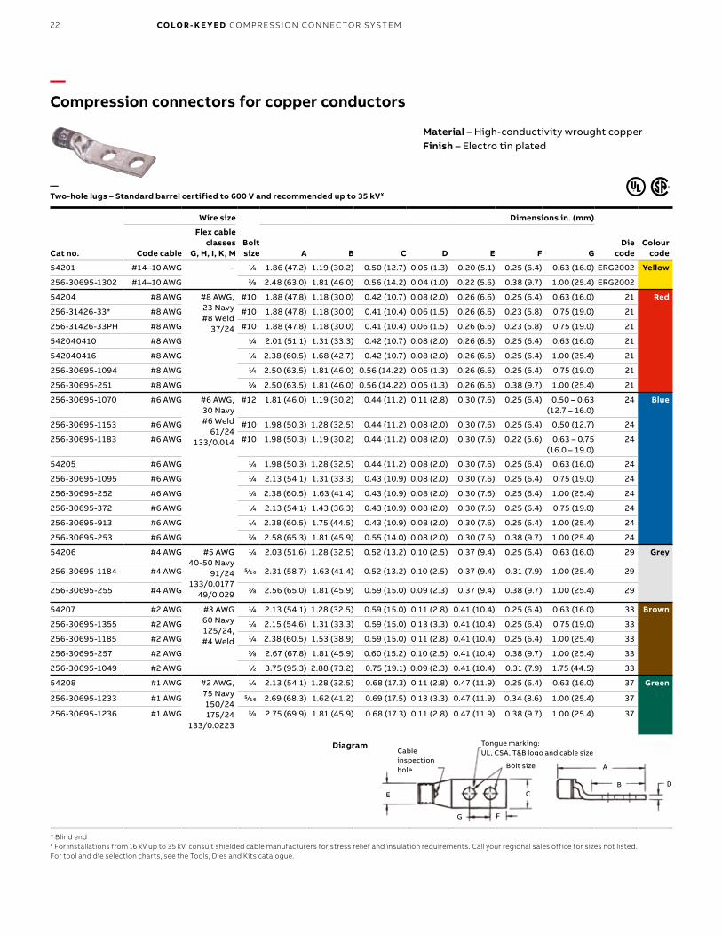
—Compression connectors for copper conductors
Material – High-conductivity wrought copperFinish – Electro tin plated
Cat no.
Wire size
Bolt size
Dimensions in. (mm)
Die code
Colour codeCode cable
Flex cable classes
G, H, I, K, M A B C D E F G
54201 #14–10 AWG – 1/4 1.86 (47.2) 1.19 (30.2) 0.50 (12.7) 0.05 (1.3) 0.20 (5.1) 0.25 (6.4) 0.63 (16.0) ERG2002 Yellow
256-30695-1302 #14–10 AWG 3/8 2.48 (63.0) 1.81 (46.0) 0.56 (14.2) 0.04 (1.0) 0.22 (5.6) 0.38 (9.7) 1.00 (25.4) ERG2002
54204 #8 AWG #8 AWG, 23 Navy#8 Weld
37/24
#10 1.88 (47.8) 1.18 (30.0) 0.42 (10.7) 0.08 (2.0) 0.26 (6.6) 0.25 (6.4) 0.63 (16.0) 21 Red
256-31426-33* #8 AWG #10 1.88 (47.8) 1.18 (30.0) 0.41 (10.4) 0.06 (1.5) 0.26 (6.6) 0.23 (5.8) 0.75 (19.0) 21
256-31426-33PH #8 AWG #10 1.88 (47.8) 1.18 (30.0) 0.41 (10.4) 0.06 (1.5) 0.26 (6.6) 0.23 (5.8) 0.75 (19.0) 21
542040410 #8 AWG 1/4 2.01 (51.1) 1.31 (33.3) 0.42 (10.7) 0.08 (2.0) 0.26 (6.6) 0.25 (6.4) 0.63 (16.0) 21
542040416 #8 AWG 1/4 2.38 (60.5) 1.68 (42.7) 0.42 (10.7) 0.08 (2.0) 0.26 (6.6) 0.25 (6.4) 1.00 (25.4) 21
256-30695-1094 #8 AWG 1/4 2.50 (63.5) 1.81 (46.0) 0.56 (14.22) 0.05 (1.3) 0.26 (6.6) 0.25 (6.4) 0.75 (19.0) 21
256-30695-251 #8 AWG 3/8 2.50 (63.5) 1.81 (46.0) 0.56 (14.22) 0.05 (1.3) 0.26 (6.6) 0.38 (9.7) 1.00 (25.4) 21
256-30695-1070 #6 AWG #6 AWG, 30 Navy#6 Weld
61/24133/0.014
#12 1.81 (46.0) 1.19 (30.2) 0.44 (11.2) 0.11 (2.8) 0.30 (7.6) 0.25 (6.4) 0.50 – 0.63 (12.7 – 16.0)
24 Blue
256-30695-1153 #6 AWG #10 1.98 (50.3) 1.28 (32.5) 0.44 (11.2) 0.08 (2.0) 0.30 (7.6) 0.25 (6.4) 0.50 (12.7) 24
256-30695-1183 #6 AWG #10 1.98 (50.3) 1.19 (30.2) 0.44 (11.2) 0.08 (2.0) 0.30 (7.6) 0.22 (5.6) 0.63 – 0.75 (16.0 – 19.0)
24
54205 #6 AWG 1/4 1.98 (50.3) 1.28 (32.5) 0.44 (11.2) 0.08 (2.0) 0.30 (7.6) 0.25 (6.4) 0.63 (16.0) 24
256-30695-1095 #6 AWG 1/4 2.13 (54.1) 1.31 (33.3) 0.43 (10.9) 0.08 (2.0) 0.30 (7.6) 0.25 (6.4) 0.75 (19.0) 24
256-30695-252 #6 AWG 1/4 2.38 (60.5) 1.63 (41.4) 0.43 (10.9) 0.08 (2.0) 0.30 (7.6) 0.25 (6.4) 1.00 (25.4) 24
256-30695-372 #6 AWG 1/4 2.13 (54.1) 1.43 (36.3) 0.43 (10.9) 0.08 (2.0) 0.30 (7.6) 0.25 (6.4) 0.75 (19.0) 24
256-30695-913 #6 AWG 1/4 2.38 (60.5) 1.75 (44.5) 0.43 (10.9) 0.08 (2.0) 0.30 (7.6) 0.25 (6.4) 1.00 (25.4) 24
256-30695-253 #6 AWG 3/8 2.58 (65.3) 1.81 (45.9) 0.55 (14.0) 0.08 (2.0) 0.30 (7.6) 0.38 (9.7) 1.00 (25.4) 24
54206 #4 AWG #5 AWG40-50 Navy
91/24133/0.0177
49/0.029
1/4 2.03 (51.6) 1.28 (32.5) 0.52 (13.2) 0.10 (2.5) 0.37 (9.4) 0.25 (6.4) 0.63 (16.0) 29 Grey
256-30695-1184 #4 AWG 5⁄16 2.31 (58.7) 1.63 (41.4) 0.52 (13.2) 0.10 (2.5) 0.37 (9.4) 0.31 (7.9) 1.00 (25.4) 29
256-30695-255 #4 AWG 3/8 2.56 (65.0) 1.81 (45.9) 0.59 (15.0) 0.09 (2.3) 0.37 (9.4) 0.38 (9.7) 1.00 (25.4) 29
54207 #2 AWG #3 AWG60 Navy125/24, #4 Weld
1/4 2.13 (54.1) 1.28 (32.5) 0.59 (15.0) 0.11 (2.8) 0.41 (10.4) 0.25 (6.4) 0.63 (16.0) 33 Brown
256-30695-1355 #2 AWG 1/4 2.15 (54.6) 1.31 (33.3) 0.59 (15.0) 0.13 (3.3) 0.41 (10.4) 0.25 (6.4) 0.75 (19.0) 33
256-30695-1185 #2 AWG 1/4 2.38 (60.5) 1.53 (38.9) 0.59 (15.0) 0.11 (2.8) 0.41 (10.4) 0.25 (6.4) 1.00 (25.4) 33
256-30695-257 #2 AWG 3/8 2.67 (67.8) 1.81 (45.9) 0.60 (15.2) 0.10 (2.5) 0.41 (10.4) 0.38 (9.7) 1.00 (25.4) 33
256-30695-1049 #2 AWG 1/2 3.75 (95.3) 2.88 (73.2) 0.75 (19.1) 0.09 (2.3) 0.41 (10.4) 0.31 (7.9) 1.75 (44.5) 33
54208 #1 AWG #2 AWG, 75 Navy150/24175/24
133/0.0223
1/4 2.13 (54.1) 1.28 (32.5) 0.68 (17.3) 0.11 (2.8) 0.47 (11.9) 0.25 (6.4) 0.63 (16.0) 37 Green
256-30695-1233 #1 AWG 5⁄16 2.69 (68.3) 1.62 (41.2) 0.69 (17.5) 0.13 (3.3) 0.47 (11.9) 0.34 (8.6) 1.00 (25.4) 37
256-30695-1236 #1 AWG 3/8 2.75 (69.9) 1.81 (45.9) 0.68 (17.3) 0.11 (2.8) 0.47 (11.9) 0.38 (9.7) 1.00 (25.4) 37
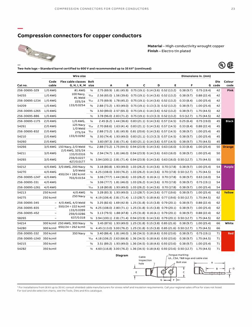
—Two-hole lugs – Standard barrel certified to 600 V and recommended up to 35 kV¥
* Blind end¥ For installations from 16 kV up to 35 kV, consult shielded cable manufacturers for stress relief and insulation requirements. Call your regional sales office for sizes not listed.For tool and die selection charts, see the Tools, Dies and Kits catalogue.
Diagram
E C
F
Cable inspection hole Bolt size
Tongue marking: UL, CSA, T&B logo and cable size
G
DB
A
23
—Compression connectors for copper conductors
Cat no.
Wire size
Bolt size
Dimensions in. (mm)
Die code
Colour code
Code cable
Flex cable classes G, H, I, K, M A B C D E F G
256-30695-329 1/0 AWG #1 AWG100 Navy,
#1 Weld225/24
133/0.0254
1/4 2.75 (69.9) 1.81 (45.9) 0.75 (19.1) 0.14 (3.6) 0.52 (13.2) 0.38 (9.7) 0.75 (19.4) 42 Pink
54255 1/0 AWG 5⁄16 2.56 (65.0) 1.56 (39.6) 0.75 (19.1) 0.14 (3.6) 0.52 (13.2) 0.38 (9.7) 0.88 (22.4) 42
256-30695-1234 1/0 AWG 5⁄16 2.75 (69.9) 1.78 (45.2) 0.75 (19.1) 0.14 (3.6) 0.52 (13.2) 0.33 (8.4) 1.00 (25.4) 42
54209 1/0 AWG 3/8 2.88 (73.2) 1.93 (49.0) 0.75 (19.1) 0.13 (3.3) 0.52 (13.2) 0.38 (9.7) 1.00 (25.4) 42
256-30695-1265 1/0 AWG 3/8 3.50 (89.0) 2.57 (65.3) 0.75 (19.1) 0.14 (3.6) 0.52 (13.2) 0.38 (9.7) 1.75 (44.5) 42
256-30695-886 1/0 AWG 1/2 3.78 (96.0) 2.83 (71.2) 0.75 (19.1) 0.13 (3.3) 0.52 (13.2) 0.5 (12.7) 1.75 (44.5) 42
256-30695-1175 2/0 AWG 1/0 AWG, 125 Navy1/0 Weld
275/24133/0.0282
1/4 2.45 (6.2) 1.44 (36.6) 0.83 (21.1) 0.14 (3.6) 0.57 (14.5) 0.25 (6.4) 0.75 (19.0) 45 Black
54261 2/0 AWG 5⁄16 2.70 (68.6) 1.63 (41.4) 0.83 (21.1) 0.14 (3.6) 0.57 (14.5) 0.33 (8.4) 0.88 (22.4) 45
256-30695-832 2/0 AWG 5⁄16 2.88 (73.2) 1.81 (45.9) 0.81 (20.6) 0.14 (3.6) 0.57 (14.5) 0.38 (9.7) 1.00 (25.4) 45
54210 2/0 AWG 3/8 2.93 (74.4) 1.93 (49.0) 0.83 (21.1) 0.13 (3.3) 0.57 (14.5) 0.38 (9.7) 1.00 (25.4) 45
54260 2/0 AWG 1/2 3.83 (97.3) 2.81 (71.4) 0.83 (21.1) 0.14 (3.6) 0.57 (14.5) 0.38 (9.7) 1.75 (44.5) 45
54266 3/0 AWG 150 Navy, 2/0 Weld2/0 AWG, 325/24
133/0.0316259/0.0227427/0.0177
5⁄16 2.88 (73.2) 1.75 (44.5) 0.94 (23.9) 0.14 (3.6) 0.63 (16.0) 0.33 (8.4) 1.00 (25.4) 50 Orange
54211 3/0 AWG 3/8 2.94 (74.7) 1.81 (46.0) 0.94 (23.9) 0.14 (3.6) 0.63 (16.0) 0.38 (9.7) 1.00 (25.4) 50
54265 3/0 AWG 1/2 3.94 (100.1) 2.81 (71.4) 0.94 (23.9) 0.14 (3.6) 0.63 (16.0) 0.50 (12.7) 1.75 (44.5) 50
54212 4/0 AWG 3/0 AWG, 200 Navy3/0 Weld
450/24 = 182 kcmil703/0.0154
3/8 3.18 (80.8) 1.93 (49.0) 1.03 (26.2) 0.14 (3.6) 0.70 (17.8) 0.38 (9.7) 1.00 (25.4) 54 Purple
54270 4/0 AWG 1/2 4.25 (108.0) 3.00 (76.2) 1.03 (26.2) 0.14 (3.6) 0.70 (17.8) 0.50 (12.7) 1.75 (44.5) 54
256-30695-1247 4/0 AWG 1/4 3.06 (77.7) 1.44 (36.6) 1.03 (26.2) 0.16 (4.1) 0.70 (17.8) 0.38 (9.7) 0.63 (16.0) 54
256-30695-331 4/0 AWG 1/4 3.06 (77.7) 1.81 (46.0) 1.03 (26.2) 0.14 (3.6) 0.70 (17.8) 0.38 (9.7) 0.75 (19.1) 54
256-30695-1261 4/0 AWG 5⁄16 3.18 (80.8) 1.93 (49.0) 1.03 (26.2) 0.14 (3.6) 0.70 (17.8) 0.38 (9.7) 1.00 (25.4) 54
54213 250 kcmil 4/0 AWG250 Navy
3/8 3.28 (83.3) 1.93 (49.0) 1.13 (28.7) 0.14 (3.6) 0.77 (19.6) 0.38 (9.7) 1.00 (25.4) 62 Yellow
54275 250 kcmil 1/2 4.19 (106.4) 2.81 (71.4) 1.13 (28.7) 0.18 (4.6) 0.77 (19.6) 0.50 (12.7) 1.75 (44.5) 62
256-30695-345 – 4/0 AWG, 4/0 Weld550/24 = 222 kcmil
133/0.0399259/0.0286
637/0.018
3/8 3.25 (82.6) 1.69 (42.9) 1.25 (31.8) 0.15 (3.8) 0.79 (20.1) 0.38 (9.7) 0.88 (22.4) 62
256-30695-835 – 3/8 4.25 (108.0) 2.80 (71.1) 1.25 (31.8) 0.15 (3.8) 0.79 (20.1) 0.38 (9.7) 1.00 (25.4) 62
256-30695-452 – 3/8 3.13 (79.5) 1.88 (47.8) 1.25 (31.8) 0.16 (4.1) 0.79 (20.1) 0.38 (9.7) 0.88 (22.4) 62
58265 – 1/2 3.94 (100.1) 2.81 (71.4) 0.94 (23.9) 0.14 (3.6) 0.79 (20.1) 0.50 (12.7) 1.75 (44.5) 62
54214 300 kcmil 250 AWG, 300 Navy650/24 = 262 kcmil
3/8 3.45 (87.6) 1.93 (49.0) 1.25 (31.8) 0.15 (3.8) 0.85 (21.6) 0.38 (9.7) 1.00 (25.4) 66 White
54280 300 kcmil 1/2 4.45 (113.0) 3.00 (76.2) 1.25 (31.8) 0.15 (3.8) 0.85 (21.6) 0.50 (12.7) 1.75 (44.5) 66
256-30695-332 350 kcmil 350 Navy 1/4 3.40 (86.4) 1.81 (46.0) 1.36 (34.5) 0.18 (4.6) 0.93 (23.6) 0.38 (9.7) 0.75 (19.1) 71 Red
256-30695-1240 350 kcmil 5⁄16 4.18 (106.2) 2.63 (66.8) 1.36 (34.5) 0.18 (4.6) 0.93 (23.6) 0.38 (9.7) 1.75 (44.5) 71
54215 350 kcmil 3/8 3.51 (89.2) 1.93 (49.0) 1.36 (34.5) 0.18 (4.6) 0.93 (23.6) 0.38 (9.7) 1.00 (25.4) 71
54282 350 kcmil 1/2 4.60 (116.8) 3.00 (76.2) 1.36 (34.5) 0.18 (4.6) 0.93 (23.6) 0.50 (12.7) 1.75 (44.5) 71
—Two-hole lugs – Standard barrel certified to 600 V and recommended up to 35 kV¥ (continued)
¥ For installations from 16 kV up to 35 kV, consult shielded cable manufacturers for stress relief and insulation requirements. Call your regional sales office for sizes not listed.For tool and die selection charts, see the Tools, Dies and Kits catalogue.
Diagram
Material – High-conductivity wrought copperFinish – Electro tin plated
E
F
Cable inspection hole Bolt size
Tongue marking: UL, CSA, T&B logo and cable size
G
DB
A
C
CO M PR E SSI O N CO N N EC TO R S FO R CO PPER CO N D U C TO R S
B1 copy starts here
B2 copy starts here
B3 copy starts here
24 CO LO R- K E Y E D CO M PR E SSI O N CO N N EC TO R S Y S TEM
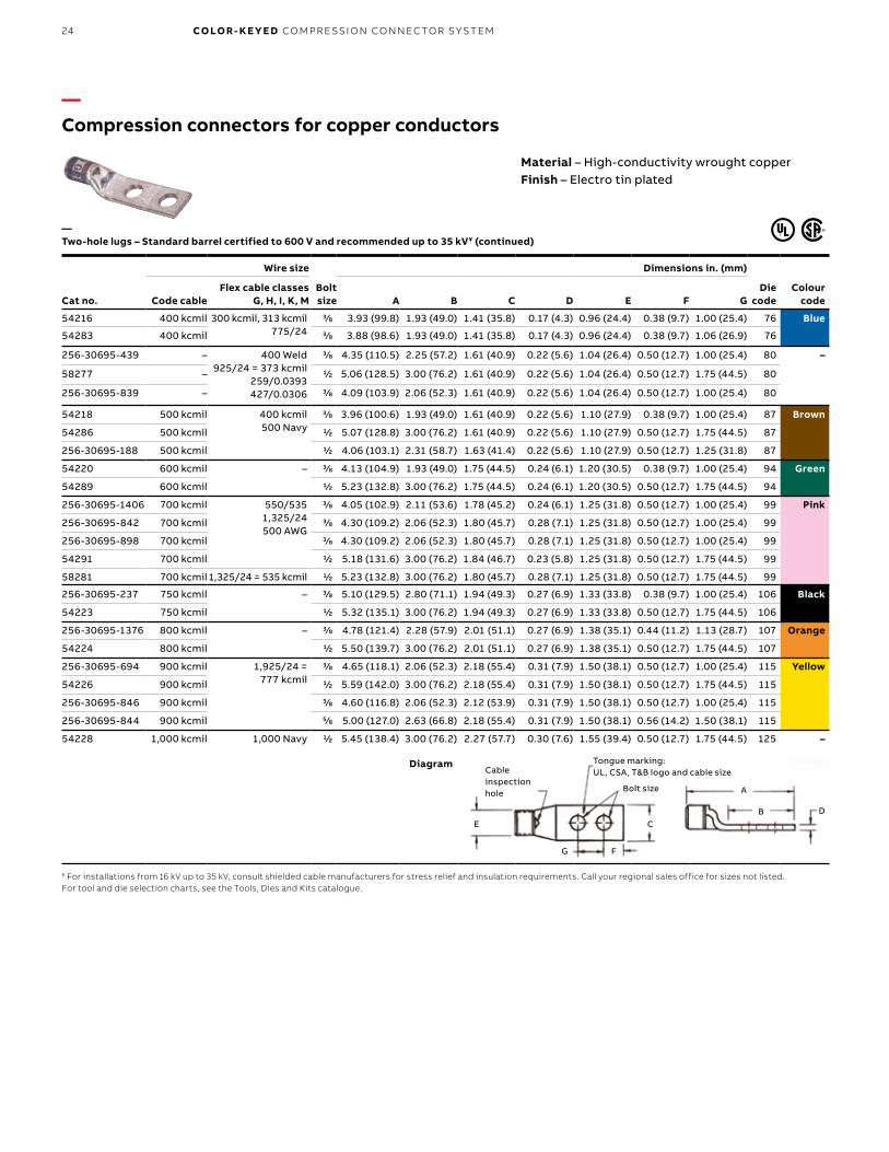
—Compression connectors for copper conductors
Cat no.
Wire size
Bolt size
Dimensions in. (mm)
Die code
Colour codeCode cable
Flex cable classes G, H, I, K, M A B C D E F G
54216 400 kcmil 300 kcmil, 313 kcmil775/24
3/8 3.93 (99.8) 1.93 (49.0) 1.41 (35.8) 0.17 (4.3) 0.96 (24.4) 0.38 (9.7) 1.00 (25.4) 76 Blue
54283 400 kcmil 3/8 3.88 (98.6) 1.93 (49.0) 1.41 (35.8) 0.17 (4.3) 0.96 (24.4) 0.38 (9.7) 1.06 (26.9) 76
256-30695-439 – 400 Weld925/24 = 373 kcmil
259/0.0393427/0.0306
3/8 4.35 (110.5) 2.25 (57.2) 1.61 (40.9) 0.22 (5.6) 1.04 (26.4) 0.50 (12.7) 1.00 (25.4) 80 –
58277 – 1/2 5.06 (128.5) 3.00 (76.2) 1.61 (40.9) 0.22 (5.6) 1.04 (26.4) 0.50 (12.7) 1.75 (44.5) 80
256-30695-839 – 3/8 4.09 (103.9) 2.06 (52.3) 1.61 (40.9) 0.22 (5.6) 1.04 (26.4) 0.50 (12.7) 1.00 (25.4) 80
54218 500 kcmil 400 kcmil500 Navy
3/8 3.96 (100.6) 1.93 (49.0) 1.61 (40.9) 0.22 (5.6) 1.10 (27.9) 0.38 (9.7) 1.00 (25.4) 87 Brown
54286 500 kcmil 1/2 5.07 (128.8) 3.00 (76.2) 1.61 (40.9) 0.22 (5.6) 1.10 (27.9) 0.50 (12.7) 1.75 (44.5) 87
256-30695-188 500 kcmil 1/2 4.06 (103.1) 2.31 (58.7) 1.63 (41.4) 0.22 (5.6) 1.10 (27.9) 0.50 (12.7) 1.25 (31.8) 87
54220 600 kcmil – 3/8 4.13 (104.9) 1.93 (49.0) 1.75 (44.5) 0.24 (6.1) 1.20 (30.5) 0.38 (9.7) 1.00 (25.4) 94 Green
54289 600 kcmil 1/2 5.23 (132.8) 3.00 (76.2) 1.75 (44.5) 0.24 (6.1) 1.20 (30.5) 0.50 (12.7) 1.75 (44.5) 94
256-30695-1406 700 kcmil 550/5351,325/24500 AWG
3/8 4.05 (102.9) 2.11 (53.6) 1.78 (45.2) 0.24 (6.1) 1.25 (31.8) 0.50 (12.7) 1.00 (25.4) 99 Pink
256-30695-842 700 kcmil 3/8 4.30 (109.2) 2.06 (52.3) 1.80 (45.7) 0.28 (7.1) 1.25 (31.8) 0.50 (12.7) 1.00 (25.4) 99
256-30695-898 700 kcmil 3/8 4.30 (109.2) 2.06 (52.3) 1.80 (45.7) 0.28 (7.1) 1.25 (31.8) 0.50 (12.7) 1.00 (25.4) 99
54291 700 kcmil 1/2 5.18 (131.6) 3.00 (76.2) 1.84 (46.7) 0.23 (5.8) 1.25 (31.8) 0.50 (12.7) 1.75 (44.5) 99
58281 700 kcmil1,325/24 = 535 kcmil 1/2 5.23 (132.8) 3.00 (76.2) 1.80 (45.7) 0.28 (7.1) 1.25 (31.8) 0.50 (12.7) 1.75 (44.5) 99
256-30695-237 750 kcmil – 3/8 5.10 (129.5) 2.80 (71.1) 1.94 (49.3) 0.27 (6.9) 1.33 (33.8) 0.38 (9.7) 1.00 (25.4) 106 Black
54223 750 kcmil 1/2 5.32 (135.1) 3.00 (76.2) 1.94 (49.3) 0.27 (6.9) 1.33 (33.8) 0.50 (12.7) 1.75 (44.5) 106
256-30695-1376 800 kcmil – 3/8 4.78 (121.4) 2.28 (57.9) 2.01 (51.1) 0.27 (6.9) 1.38 (35.1) 0.44 (11.2) 1.13 (28.7) 107 Orange
54224 800 kcmil 1/2 5.50 (139.7) 3.00 (76.2) 2.01 (51.1) 0.27 (6.9) 1.38 (35.1) 0.50 (12.7) 1.75 (44.5) 107
256-30695-694 900 kcmil 1,925/24 = 777 kcmil
3/8 4.65 (118.1) 2.06 (52.3) 2.18 (55.4) 0.31 (7.9) 1.50 (38.1) 0.50 (12.7) 1.00 (25.4) 115 Yellow
54226 900 kcmil 1/2 5.59 (142.0) 3.00 (76.2) 2.18 (55.4) 0.31 (7.9) 1.50 (38.1) 0.50 (12.7) 1.75 (44.5) 115
256-30695-846 900 kcmil 3/8 4.60 (116.8) 2.06 (52.3) 2.12 (53.9) 0.31 (7.9) 1.50 (38.1) 0.50 (12.7) 1.00 (25.4) 115
256-30695-844 900 kcmil 5/8 5.00 (127.0) 2.63 (66.8) 2.18 (55.4) 0.31 (7.9) 1.50 (38.1) 0.56 (14.2) 1.50 (38.1) 115
54228 1,000 kcmil 1,000 Navy 1/2 5.45 (138.4) 3.00 (76.2) 2.27 (57.7) 0.30 (7.6) 1.55 (39.4) 0.50 (12.7) 1.75 (44.5) 125 –
¥ For installations from 16 kV up to 35 kV, consult shielded cable manufacturers for stress relief and insulation requirements. Call your regional sales office for sizes not listed.For tool and die selection charts, see the Tools, Dies and Kits catalogue.
Diagram
—Two-hole lugs – Standard barrel certified to 600 V and recommended up to 35 kV¥ (continued)
Material – High-conductivity wrought copperFinish – Electro tin plated
E
F
Cable inspection hole Bolt size
Tongue marking: UL, CSA, T&B logo and cable size
G
DB
A
C

25
—Compression connectors for copper conductors
Material – High-conductivity wrought copperFinish – Electro tin plated
Cat no.
Wire size
Bolt size
Dimensions in. (mm)
Die code
Colour codeCode cable
Flex cable classes G, H, I, K, M B C D E F G
256-31426-9 #14–10 AWG – #10 1.22 (31.0) 0.37 (9.4) 0.05 (1.3) 0.20 (5.1) 0.25 (6.4) 0.63 (16.0) – –
54204UF #8 AWG #8 AWG, 23 Navy#8 Weld, 37/24
#10 1.18 (30.0) 0.42 (10.7) 0.08 (2.0) 0.26 (6.6) 0.25 (6.4) 0.63 (16.0) 21 Red
256-30695-1183UF #6 AWG #6 AWG, 30 Navy#6 Weld
61/24133/0.014
#10 1.19 (30.2) 0.44 (11.2) 0.08 (2.0) 0.30 (7.6) 0.22 (5.6) 0.63 – 0.75 (16.0) – (19.1)
24 Blue
54205UF #6 AWG 1/4 1.28 (32.5) 0.44 (11.2) 0.08 (2.0) 0.30 (7.6) 0.25 (6.4) 0.63 (16.0) 24
54205UF0416 #6 AWG 1/4 1.56 (39.6) 0.43 (10.9) 0.08 (2.0) 0.30 (7.6) 0.25 (6.4) 1.00 (25.4) 24
54206UF #4 AWG #5 AWG40-50 Navy, 91/24
133/0.017749/0.029
1/4 1.28 (32.5) 0.52 (13.2) 0.10 (2.5) 0.37 (9.4) 0.25 (6.4) 0.63 (16.0) 29 Grey
54207UF #2 AWG #3 AWG60 Navy, #4 Weld
125/24
1/4 1.28 (32.5) 0.59 (15.0) 0.11 (2.8) 0.41 (10.4) 0.25 (6.4) 0.63 (16.0) 33 Brown
256-30695-257UF #2 AWG 3/8 1.81 (46.0) 0.60 (15.2) 0.11 (2.8) 0.41 (10.4) 0.38 (9.7) 1.00 (25.4) 33
54208UF #1 AWG #2 AWG, 75 Navy150/24, 175/24
133/0.0223
1/4 1.28 (32.5) 0.68 (17.3) 0.11 (2.8) 0.47 (11.9) 0.25 (6.4) 0.63 (16.0) 37 Green
54209UF 1/0 AWG #1 AWG100 Navy, #1 Weld
225/24133/0.0254
3/8 1.93 (49.0) 0.75 (19.1) 0.13 (3.3) 0.52 (13.2) 0.38 (9.7) 1.00 (25.4) 42 Pink
54209UF0412 1/0 AWG 1/4 1.55 (39.4) 0.75 (19.1) 0.13 (3.3) 0.52 (13.2) 0.25 (6.4) 0.75 (19.1) 42
54261UF 2/0 AWG 1/0 AWG, 125 Navy1/0 Weld
275/24133/0.0282
5⁄16 1.63 (41.4) 0.83 (21.1) 0.14 (3.6) 0.57 (14.5) 0.33 (8.4) 0.88 (22.4) 45 Black
54210UF 2/0 AWG 3/8 1.93 (49.0) 0.83 (21.1) 0.13 (3.3) 0.57 (14.5) 0.38 (9.7) 1.00 (25.4) 45
54260UF 2/0 AWG 1/2 2.81 (71.4) 0.83 (21.1) 0.14 (3.6) 0.57 (14.5) 0.38 (9.7) 1.75 (44.5) 45
54266UF 3/0 AWG 2/0 AWG, 150 Navy2/0 Weld, 325/24
133/0.0316259/0.0227427/0.0177
5⁄16 1.75 (44.5) 0.94 (23.9) 0.14 (3.6) 0.63 (16.0) 0.33 (8.4) 1.00 (25.4) 50 Orange
54211UF 3/0 AWG 3/8 1.81 (46.0) 0.94 (23.9) 0.14 (3.6) 0.63 (16.0) 0.38 (9.7) 1.00 (25.4) 50
54265UF 3/0 AWG 1/2 2.81 (71.4) 0.94 (23.9) 0.14 (3.6) 0.63 (16.0) 0.25 (6.4) 1.75 (44.5) 50
54212UF 4/0 AWG 200 Navy, 3/0 AWG3/0 Weld
450/24, 703/0.0154
3/8 1.93 (49.0) 1.03 (26.2) 0.14 (3.6) 0.70 (17.8) 0.38 (9.7) 1.00 (25.4) 54 Purple
54270UF 4/0 AWG 1/2 3.00 (76.2) 1.03 (26.2) 0.14 (3.6) 0.70 (17.8) 0.25 (6.4) 1.75 (44.5) 54
—Two-hole lugs – 45° Standard barrel certified to 600 V and recommended up to 35 kV¥
¥ For installations from 16 kV up to 35 kV, consult shielded cable manufacturers for stress relief and insulation requirements. Call your regional sales office for sizes not listed.For tool and die selection charts, see the Tools, Dies and Kits catalogue.
Diagram
E C
F
DB 45° ± 3°
Bolt size
CO M PR E SSI O N CO N N EC TO R S FO R CO PPER CO N D U C TO R S
B1 copy starts here
B2 copy starts here
B3 copy starts here
26 CO LO R- K E Y E D CO M PR E SSI O N CO N N EC TO R S Y S TEM
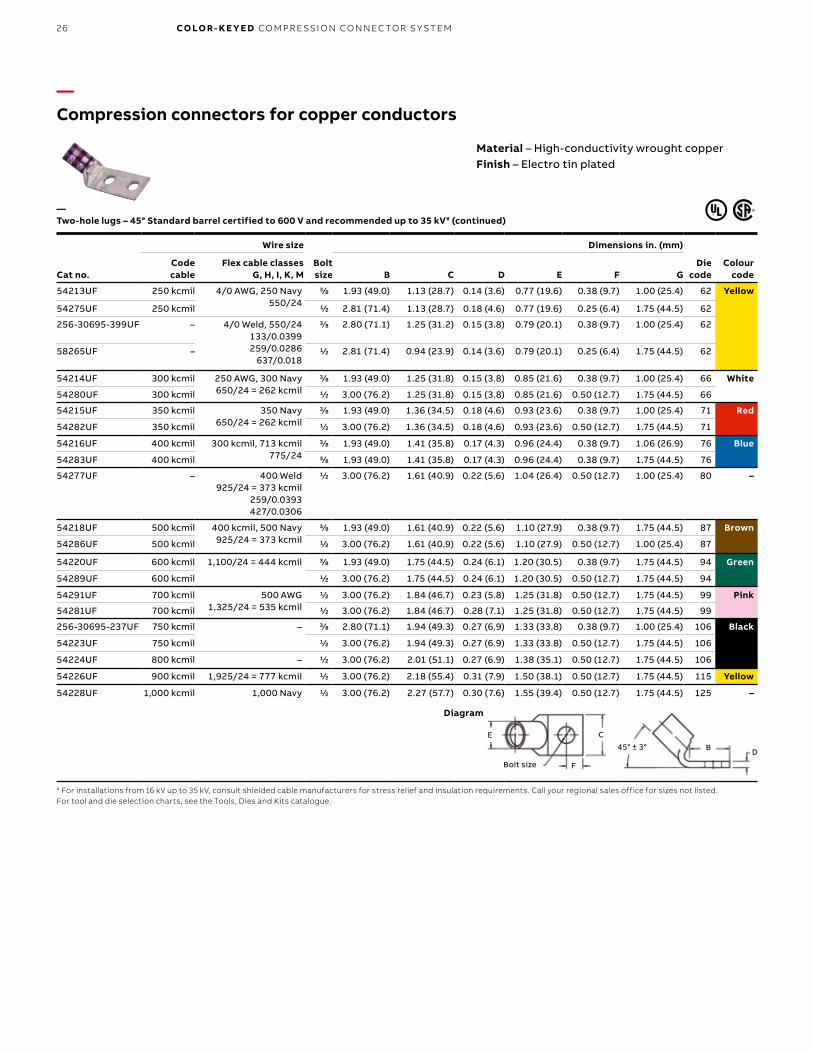
—Compression connectors for copper conductors
Cat no.
Wire size
Bolt size
Dimensions in. (mm)
Die code
Colour code
Code cable
Flex cable classes G, H, I, K, M B C D E F G
54213UF 250 kcmil 4/0 AWG, 250 Navy550/24
3/8 1.93 (49.0) 1.13 (28.7) 0.14 (3.6) 0.77 (19.6) 0.38 (9.7) 1.00 (25.4) 62 Yellow
54275UF 250 kcmil 1/2 2.81 (71.4) 1.13 (28.7) 0.18 (4.6) 0.77 (19.6) 0.25 (6.4) 1.75 (44.5) 62
256-30695-399UF – 4/0 Weld, 550/24133/0.0399259/0.0286
637/0.018
3/8 2.80 (71.1) 1.25 (31.2) 0.15 (3.8) 0.79 (20.1) 0.38 (9.7) 1.00 (25.4) 62
58265UF – 1/2 2.81 (71.4) 0.94 (23.9) 0.14 (3.6) 0.79 (20.1) 0.25 (6.4) 1.75 (44.5) 62
54214UF 300 kcmil 250 AWG, 300 Navy650/24 = 262 kcmil
3/8 1.93 (49.0) 1.25 (31.8) 0.15 (3.8) 0.85 (21.6) 0.38 (9.7) 1.00 (25.4) 66 White
54280UF 300 kcmil 1/2 3.00 (76.2) 1.25 (31.8) 0.15 (3.8) 0.85 (21.6) 0.50 (12.7) 1.75 (44.5) 66
54215UF 350 kcmil 350 Navy650/24 = 262 kcmil
3/8 1.93 (49.0) 1.36 (34.5) 0.18 (4.6) 0.93 (23.6) 0.38 (9.7) 1.00 (25.4) 71 Red
54282UF 350 kcmil 1/2 3.00 (76.2) 1.36 (34.5) 0.18 (4.6) 0.93 (23.6) 0.50 (12.7) 1.75 (44.5) 71
54216UF 400 kcmil 300 kcmil, 713 kcmil775/24
3/8 1.93 (49.0) 1.41 (35.8) 0.17 (4.3) 0.96 (24.4) 0.38 (9.7) 1.06 (26.9) 76 Blue
54283UF 400 kcmil 3/8 1.93 (49.0) 1.41 (35.8) 0.17 (4.3) 0.96 (24.4) 0.38 (9.7) 1.75 (44.5) 76
54277UF – 400 Weld925/24 = 373 kcmil
259/0.0393427/0.0306
1/2 3.00 (76.2) 1.61 (40.9) 0.22 (5.6) 1.04 (26.4) 0.50 (12.7) 1.00 (25.4) 80 –
54218UF 500 kcmil 400 kcmil, 500 Navy925/24 = 373 kcmil
3/8 1.93 (49.0) 1.61 (40.9) 0.22 (5.6) 1.10 (27.9) 0.38 (9.7) 1.75 (44.5) 87 Brown
54286UF 500 kcmil 1/2 3.00 (76.2) 1.61 (40.9) 0.22 (5.6) 1.10 (27.9) 0.50 (12.7) 1.00 (25.4) 87
54220UF 600 kcmil 1,100/24 = 444 kcmil 3/8 1.93 (49.0) 1.75 (44.5) 0.24 (6.1) 1.20 (30.5) 0.38 (9.7) 1.75 (44.5) 94 Green
54289UF 600 kcmil 1/2 3.00 (76.2) 1.75 (44.5) 0.24 (6.1) 1.20 (30.5) 0.50 (12.7) 1.75 (44.5) 94
54291UF 700 kcmil 500 AWG1,325/24 = 535 kcmil
1/2 3.00 (76.2) 1.84 (46.7) 0.23 (5.8) 1.25 (31.8) 0.50 (12.7) 1.75 (44.5) 99 Pink
54281UF 700 kcmil 1/2 3.00 (76.2) 1.84 (46.7) 0.28 (7.1) 1.25 (31.8) 0.50 (12.7) 1.75 (44.5) 99
256-30695-237UF 750 kcmil – 3/8 2.80 (71.1) 1.94 (49.3) 0.27 (6.9) 1.33 (33.8) 0.38 (9.7) 1.00 (25.4) 106 Black
54223UF 750 kcmil 1/2 3.00 (76.2) 1.94 (49.3) 0.27 (6.9) 1.33 (33.8) 0.50 (12.7) 1.75 (44.5) 106
54224UF 800 kcmil – 1/2 3.00 (76.2) 2.01 (51.1) 0.27 (6.9) 1.38 (35.1) 0.50 (12.7) 1.75 (44.5) 106
54226UF 900 kcmil 1,925/24 = 777 kcmil 1/2 3.00 (76.2) 2.18 (55.4) 0.31 (7.9) 1.50 (38.1) 0.50 (12.7) 1.75 (44.5) 115 Yellow
54228UF 1,000 kcmil 1,000 Navy 1/2 3.00 (76.2) 2.27 (57.7) 0.30 (7.6) 1.55 (39.4) 0.50 (12.7) 1.75 (44.5) 125 –
—Two-hole lugs – 45° Standard barrel certified to 600 V and recommended up to 35 kV¥ (continued)
¥ For installations from 16 kV up to 35 kV, consult shielded cable manufacturers for stress relief and insulation requirements. Call your regional sales office for sizes not listed.For tool and die selection charts, see the Tools, Dies and Kits catalogue.
Diagram
Material – High-conductivity wrought copperFinish – Electro tin plated
E C
F
DB 45° ± 3°
Bolt size

27
—Compression connectors for copper conductors
Cat no.
Wire size
Bolt size
Dimensions in. (mm)
Die code
Colour codeCode cable
Flex cable classes G, H, I, K, M B C D E F G
256-31426-141 #14–10 AWG – #10 1.25 (31.2) 0.37 (9.4) 0.07 (1.8) 0.20 (5.1) 0.22 (5.6) 0.63 (16.0) ERG2002 Yellow
256-31426-6SPH #14–10 AWG #10 1.30 (33.0) 0.37 (9.4) 0.07 (1.8) 0.20 (5.1) 0.22 (5.6) 0.63 – 0.75 (16.0) – (19.1)
ERG2002
256-31426-6 #14–10 AWG #10 1.30 (33.0) 0.37 (9.4) 0.07 (1.8) 0.20 (5.1) 0.22 (5.6) 0.63 (16.0) ERG2002
256-31426-6S #14–10 AWG #10 1.30 (33.0) 0.37 (9.4) 0.07 (1.8) 0.20 (5.1) 0.22 (5.6) 0.63 – 0.75 (16.0) – (19.1)
ERG2002
256-30695-1409 #8 AWG #8 AWG23 Navy#8 Weld
37/24
#10 1.19 (30.2) 0.41 (10.4) 0.06 (1.5) 0.26 (6.6) 0.23 (5.8) 0.63 – 0.75 (16.0) – (19.1)
21 Red
54204UB #8 AWG #10 1.25 (31.8) 0.42 (10.7) 0.08 (2.0) 0.26 (6.6) 0.25 (6.4) 0.63 (16.0) 21
256-31426-33UB* #8 AWG #10 1.19 (30.2) 0.41 (10.4) 0.06 (1.5) 0.26 (6.6) 0.23 (5.8) 0.63 (16.0) 21
256-31426-33UBPH #8 AWG #10 1.19 (30.2) 0.41 (10.4) 0.06 (1.5) 0.26 (6.6) 0.23 (5.8) 0.63 – 0.75 (16.0) – (19.1)
21
256-30695-1411 #6 AWG #6 AWG 30 Navy#6 Weld
133/0.01461/24
#10 1.19 (30.2) 0.44 (11.2) 0.08 (2.0) 0.30 (7.6) 0.23 (5.8) 0.63 – 0.75 (16.0) – (19.1)
24 Blue
256-30695-1183B #6 AWG #10 1.19 (30.2) 0.44 (11.2) 0.08 (2.0) 0.30 (7.6) 0.23 (5.8) 0.63 – 0.75 (16.0) – (19.1)
24
256-30695-1356 #6 AWG #10 1.19 (30.2) 0.43 (10.1) 0.08 (2.0) 0.30 (7.6) 0.23 (5.8) 0.63 (16.0) 24
54205UB #6 AWG 1/4 1.28 (32.5) 0.44 (11.2) 0.08 (2.0) 0.30 (7.6) 0.25 (6.4) 0.63 (16.0) 24
256-30695-252UB #6 AWG 1/4 1.56 (39.6) 0.43 (10.1) 0.08 (2.0) 0.30 (7.6) 0.25 (6.4) 1.00 (25.4) 24
54206UB #4 AWG #5 AWG 40-50 Navy, 91/24
133/0.017749/0.029
1/4 1.28 (32.5) 0.52 (13.2) 0.10 (2.5) 0.37 (9.4) 0.25 (6.4) 0.63 (16.0) 29 Grey
54207UB #2 AWG #3 AWG, 60 Navy #4 Weld, 125/24
1/4 1.28 (32.5) 0.59 (15.0) 0.11 (2.8) 0.41 (10.4) 0.25 (6.4) 0.63 (16.0) 33 Brown
54208UB #1 AWG #2 AWG, 75 Navy150/24, 133/0.0223
1/4 1.28 (32.5) 0.68 (17.3) 0.11 (2.8) 0.47 (11.9) 0.25 (6.4) 0.63 (16.0) 37 Green
54209UB 1/0 AWG 1 AWG, 100 Navy,#1 Weld, 225/24
133/0.0254
3/8 1.93 (49.0) 0.75 (19.1) 0.13 (3.3) 0.52 (13.2) 0.38 (9.7) 1.00 (25.4) 42 Pink
54209UB0412 1/0 AWG 1/4 1.55 (39.4) 0.75 (19.1) 0.13 (3.3) 0.52 (13.2) 0.25 (6.4) 0.75 (19.1) 42
54261UB 2/0 AWG 1/0 AWG, 125 Navy1/0 Weld, 275/24
133/0.0282
5⁄16 1.63 (41.4) 0.83 (21.1) 0.14 (3.6) 0.57 (14.5) 0.34 (8.6) 0.88 (22.4) 45 Black
54210UB 2/0 AWG 3/8 1.93 (49.0) 0.83 (21.1) 0.13 (3.3) 0.57 (14.5) 0.38 (9.7) 1.00 (25.4) 45
54260UB 2/0 AWG 1/2 2.81 (71.4) 0.83 (21.1) 0.14 (3.6) 0.57 (14.5) 0.38 (9.7) 1.75 (44.5) 45
—Two-hole lugs – 90° Standard barrel certified to 600 V and recommended up to 35 kV¥
* Blind end¥ For installations from 16 kV up to 35 kV, consult shielded cable manufacturers for stress relief and insulation requirements. Call your regional sales office for sizes not listed.For tool and die selection charts, see the Tools, Dies and Kits catalogue.
Diagram
Material – High-conductivity wrought copperFinish – Electro tin plated
EF
DB
90° ± 3°
Bolt size
C
CO M PR E SSI O N CO N N EC TO R S FO R CO PPER CO N D U C TO R S
B1 copy starts here
B2 copy starts here
B3 copy starts here
28 CO LO R- K E Y E D CO M PR E SSI O N CO N N EC TO R S Y S TEM
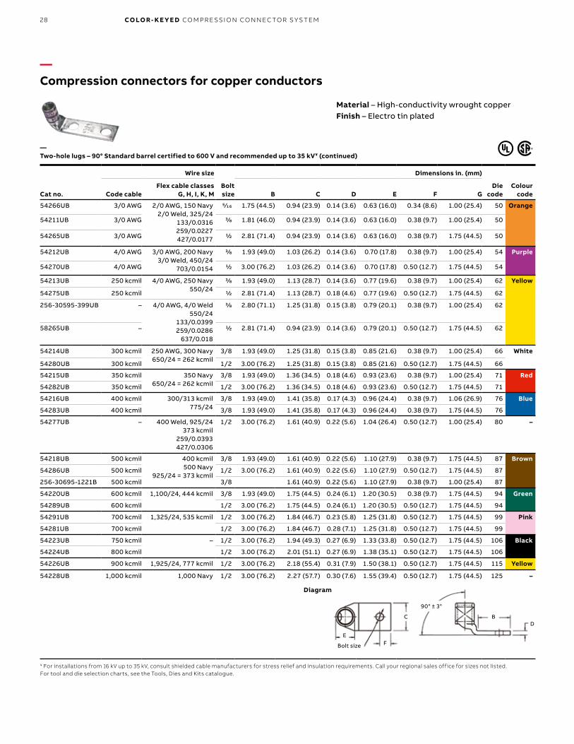
—Compression connectors for copper conductors
Cat no.
Wire size
Bolt size
Dimensions in. (mm)
Die code
Colour codeCode cable
Flex cable classes G, H, I, K, M B C D E F G
54266UB 3/0 AWG 2/0 AWG, 150 Navy2/0 Weld, 325/24
133/0.0316259/0.0227427/0.0177
5⁄16 1.75 (44.5) 0.94 (23.9) 0.14 (3.6) 0.63 (16.0) 0.34 (8.6) 1.00 (25.4) 50 Orange
54211UB 3/0 AWG 3/8 1.81 (46.0) 0.94 (23.9) 0.14 (3.6) 0.63 (16.0) 0.38 (9.7) 1.00 (25.4) 50
54265UB 3/0 AWG 1/2 2.81 (71.4) 0.94 (23.9) 0.14 (3.6) 0.63 (16.0) 0.38 (9.7) 1.75 (44.5) 50
54212UB 4/0 AWG 3/0 AWG, 200 Navy3/0 Weld, 450/24
703/0.0154
3/8 1.93 (49.0) 1.03 (26.2) 0.14 (3.6) 0.70 (17.8) 0.38 (9.7) 1.00 (25.4) 54 Purple
54270UB 4/0 AWG 1/2 3.00 (76.2) 1.03 (26.2) 0.14 (3.6) 0.70 (17.8) 0.50 (12.7) 1.75 (44.5) 54
54213UB 250 kcmil 4/0 AWG, 250 Navy550/24
3/8 1.93 (49.0) 1.13 (28.7) 0.14 (3.6) 0.77 (19.6) 0.38 (9.7) 1.00 (25.4) 62 Yellow
54275UB 250 kcmil 1/2 2.81 (71.4) 1.13 (28.7) 0.18 (4.6) 0.77 (19.6) 0.50 (12.7) 1.75 (44.5) 62
256-30595-399UB – 4/0 AWG, 4/0 Weld550/24
133/0.0399259/0.0286
637/0.018
3/8 2.80 (71.1) 1.25 (31.8) 0.15 (3.8) 0.79 (20.1) 0.38 (9.7) 1.00 (25.4) 62
58265UB – 1/2 2.81 (71.4) 0.94 (23.9) 0.14 (3.6) 0.79 (20.1) 0.50 (12.7) 1.75 (44.5) 62
54214UB 300 kcmil 250 AWG, 300 Navy650/24 = 262 kcmil
3/8 1.93 (49.0) 1.25 (31.8) 0.15 (3.8) 0.85 (21.6) 0.38 (9.7) 1.00 (25.4) 66 White
54280UB 300 kcmil 1/2 3.00 (76.2) 1.25 (31.8) 0.15 (3.8) 0.85 (21.6) 0.50 (12.7) 1.75 (44.5) 66
54215UB 350 kcmil 350 Navy650/24 = 262 kcmil
3/8 1.93 (49.0) 1.36 (34.5) 0.18 (4.6) 0.93 (23.6) 0.38 (9.7) 1.00 (25.4) 71 Red
54282UB 350 kcmil 1/2 3.00 (76.2) 1.36 (34.5) 0.18 (4.6) 0.93 (23.6) 0.50 (12.7) 1.75 (44.5) 71
54216UB 400 kcmil 300/313 kcmil775/24
3/8 1.93 (49.0) 1.41 (35.8) 0.17 (4.3) 0.96 (24.4) 0.38 (9.7) 1.06 (26.9) 76 Blue
54283UB 400 kcmil 3/8 1.93 (49.0) 1.41 (35.8) 0.17 (4.3) 0.96 (24.4) 0.38 (9.7) 1.75 (44.5) 76
54277UB – 400 Weld, 925/24373 kcmil
259/0.0393427/0.0306
1/2 3.00 (76.2) 1.61 (40.9) 0.22 (5.6) 1.04 (26.4) 0.50 (12.7) 1.00 (25.4) 80 –
54218UB 500 kcmil 400 kcmil500 Navy
925/24 = 373 kcmil
3/8 1.93 (49.0) 1.61 (40.9) 0.22 (5.6) 1.10 (27.9) 0.38 (9.7) 1.75 (44.5) 87 Brown
54286UB 500 kcmil 1/2 3.00 (76.2) 1.61 (40.9) 0.22 (5.6) 1.10 (27.9) 0.50 (12.7) 1.75 (44.5) 87
256-30695-1221B 500 kcmil 3/8 1.61 (40.9) 0.22 (5.6) 1.10 (27.9) 0.38 (9.7) 1.00 (25.4) 87
54220UB 600 kcmil 1,100/24, 444 kcmil 3/8 1.93 (49.0) 1.75 (44.5) 0.24 (6.1) 1.20 (30.5) 0.38 (9.7) 1.75 (44.5) 94 Green
54289UB 600 kcmil 1/2 3.00 (76.2) 1.75 (44.5) 0.24 (6.1) 1.20 (30.5) 0.50 (12.7) 1.75 (44.5) 94
54291UB 700 kcmil 1,325/24, 535 kcmil 1/2 3.00 (76.2) 1.84 (46.7) 0.23 (5.8) 1.25 (31.8) 0.50 (12.7) 1.75 (44.5) 99 Pink
54281UB 700 kcmil 1/2 3.00 (76.2) 1.84 (46.7) 0.28 (7.1) 1.25 (31.8) 0.50 (12.7) 1.75 (44.5) 99
54223UB 750 kcmil – 1/2 3.00 (76.2) 1.94 (49.3) 0.27 (6.9) 1.33 (33.8) 0.50 (12.7) 1.75 (44.5) 106 Black
54224UB 800 kcmil 1/2 3.00 (76.2) 2.01 (51.1) 0.27 (6.9) 1.38 (35.1) 0.50 (12.7) 1.75 (44.5) 106
54226UB 900 kcmil 1,925/24, 777 kcmil 1/2 3.00 (76.2) 2.18 (55.4) 0.31 (7.9) 1.50 (38.1) 0.50 (12.7) 1.75 (44.5) 115 Yellow
54228UB 1,000 kcmil 1,000 Navy 1/2 3.00 (76.2) 2.27 (57.7) 0.30 (7.6) 1.55 (39.4) 0.50 (12.7) 1.75 (44.5) 125 –
—Two-hole lugs – 90° Standard barrel certified to 600 V and recommended up to 35 kV¥ (continued)
¥ For installations from 16 kV up to 35 kV, consult shielded cable manufacturers for stress relief and insulation requirements. Call your regional sales office for sizes not listed.For tool and die selection charts, see the Tools, Dies and Kits catalogue.
Diagram
Material – High-conductivity wrought copperFinish – Electro tin plated
EF
DB
90° ± 3°
Bolt size
C

29
—Compression connectors for copper conductors
Cat no.
Wire size
Bolt size
Dimensions in. (mm)
Die code
Colour codeCode cable
Flex cable classes G, H, I, K, M A B C D E F
54901BE #14–10 AWG – 1/4 1.23 (31.2) 0.56 (14.2) 0.50 (12.7) 0.05 (1.3) 0.20 (5.1) 0.25 (6.4) ERG2002 –
54929BE #8 AWG #8 AWG37/24
#10 1.65 (41.9) 0.65 (16.5) 0.42 (10.7) 0.08 (2.0) 0.26 (6.6) 0.25 (6.4) 21 Red
54930BE #8 AWG 1/4 1.65 (41.9) 0.65 (16.5) 0.42 (10.7) 0.08 (2.0) 0.26 (6.6) 0.25 (6.4) 21
54904BE #6 AWG #6 AWG61/24
#10 1.65 (41.9) 0.65 (16.5) 0.44 (11.2) 0.08 (2.0) 0.30 (7.6) 0.25 (6.4) 24 Blue
54905BE #6 AWG 1/4 1.65 (41.9) 0.65 (16.5) 0.44 (11.2) 0.08 (2.0) 0.30 (7.6) 0.25 (6.4) 24
54908BE #4 AWG #5 AWG91/24
#10 1.70 (43.2) 0.65 (16.5) 0.52 (13.2) 0.10 (2.5) 0.37 (9.4) 0.25 (6.4) 29 Grey
54906BE #4 AWG 1/4 1.70 (43.2) 0.65 (16.5) 0.52 (13.2) 0.10 (2.5) 0.37 (9.4) 0.25 (6.4) 29
54933BE #2–3 AWG #3 AWG125/24
#10 1.88 (47.8) 0.65 (16.5) 0.59 (15.0) 0.11 (2.8) 0.41 (10.4) 0.25 (6.4) 33 Brown
54942BE #2–3 AWG 5⁄16 2.03 (51.6) 0.88 (22.4) 0.59 (15.0) 0.11 (2.8) 0.41 (10.4) 0.38 (9.7) 33
54945BE #1 AWG #2 AWG150/24
#10 1.95 (49.5) 0.65 (16.5) 0.68 (17.3) 0.11 (2.8) 0.47 (11.9) 0.25 (6.4) 37 Green
54947BE #1 AWG 5⁄16 2.18 (55.4) 0.88 (22.4) 0.68 (17.3) 0.11 (2.8) 0.47 (11.9) 0.38 (9.7) 37
54946BE 1/0 AWG #1 AWG225/24
#10 1.95 (49.5) 0.65 (16.5) 0.75 (19.1) 0.13 (3.3) 0.52 (13.2) 0.25 (6.4) 42 Pink
54949BE 1/0 AWG 5⁄16 2.18 (55.4) 0.88 (22.4) 0.75 (19.1) 0.13 (3.3) 0.52 (13.2) 0.38 (9.7) 42
54909BE 1/0 AWG 3/8 2.23 (56.6) 0.93 (23.6) 0.75 (19.1) 0.13 (3.3) 0.52 (13.2) 0.38 (9.7) 42
54950BE 1/0 AWG 1/2 2.55 (64.8) 1.25 (31.8) 0.75 (19.1) 0.13 (3.3) 0.52 (13.2) 0.50 (12.7) 42
54910BE 2/0 AWG 1/0 AWG275/24
3/8 2.28 (57.9) 1.25 (31.8) 0.83 (21.1) 0.13 (3.3) 0.57 (14.5) 0.38 (9.7) 45 Black
54951BE 2/0 AWG 1/2 2.60 (66.4) 1.25 (31.8) 0.83 (21.1) 0.13 (3.3) 0.57 (14.5) 0.50 (12.7) 45
54965BE 3/0 AWG 2/0 AWG, 325/24 1/2 2.70 (68.6) 1.25 (31.8) 0.92 (23.4) 0.13 (3.3) 0.63 (16.0) 0.50 (12.7) 50 Orange
256-30695-1252 4/0 AWG 3/0 AWG, 3/0 Weld450/24
1/4 2.35 (59.7) 0.65 (16.5) 1.03 (33.0) 0.14 (3.6) 0.70 (17.8) 0.75 (19.1) 54 Purple
256-30695-1253 4/0 AWG 3/8 2.95 (74.9) 1.25 (31.8) 1.03 (33.0) 0.14 (3.6) 0.70 (17.8) 0.38 (9.7) 54
54970BE 4/0 AWG 1/2 2.95 (74.9) 1.25 (31.8) 1.03 (33.0) 0.14 (3.6) 0.77 (19.6) 0.50 (12.7) 54
54913BE 250 kcmil 4/0 AWG, 4/0 Weld550/24
1/2 3.15 (80.1) 1.25 (31.8) 1.13 (28.7) 0.14 (3.6) 0.85 (21.6) 0.50 (12.7) 62 Yellow
54914BE 300 kcmil 250 kcmil650/24 = 262 kcmil
1/2 3.50 (88.9) 1.25 (31.8) 1.25 (31.8) 0.15 (3.8) 0.93 (23.6) 0.50 (12.7) 66 White
54915BE 350 kcmil – 1/2 3.68 (93.5) 1.58 (40.1) 1.36 (34.5) 0.18 (4.6) 0.96 (24.4) 0.50 (12.7) 71 Red
54916BE 400 kcmil 775/24 = 300/313 kcmil
1/2 3.75 (95.3) 1.25 (31.8) 1.41 (35.8) 0.17 (4.3) 0.96 (24.4) 0.50 (12.7) 76 Blue
54917BE 400 kcmil 5/8 4.03 (102.4) 1.58 (40.1) 1.41 (35.8) 0.17 (4.3) 1.10 (27.9) 0.63 (16.0) 76
54918BE 500 kcmil 400 kcmil925/24 = 373 kcmil
1/2 4.25 (108.0) 1.25 (31.8) 1.61 (40.9) 0.22 (5.6) 1.10 (27.9) 0.50 (12.7) 87 Brown
54919BE 500 kcmil 5/8 4.57 (116.8) 1.58 (40.1) 1.61 (40.9) 0.22 (5.6) 1.20 (30.5) 0.63 (16.0) 87
54921BE 600 kcmil 1,100/24 = 444 kcmil
1/2 4.10 (104.1) 1.25 (31.8) 1.75 (44.5) 0.24 (6.1) 1.20 (30.5) 0.50 (12.7) 94 Green
54920BE 600 kcmil 5/8 4.39 (111.6) 1.58 (40.1) 1.75 (44.5) 0.24 (6.1) 1.20 (30.5) 0.63 (16.0) 94
54979BE – 1,325/24 = 535 kcmil
1/2 4.40 (111.8) 1.25 (31.8) 1.80 (45.7) 0.24 (6.1) 1.25 (31.8) 0.50 (12.7) 99 Pink
—One-hole lugs – Long barrel certified to 600 V and recommended up to 35 kV¥
¥ For installations from 16 kV up to 35 kV, consult shielded cable manufacturers for stress relief and insulation requirements. Call your regional sales office for sizes not listed.For tool and die selection charts, see the Tools, Dies and Kits catalogue.
Diagram
Peep holes available – Add suffix PHMaterial – High-conductivity wrought copperFinish – Electro tin plated
C
F
A
DB
E
CO M PR E SSI O N CO N N EC TO R S FO R CO PPER CO N D U C TO R S

B1 copy starts here
B2 copy starts here
B3 copy starts here
30 CO LO R- K E Y E D CO M PR E SSI O N CO N N EC TO R S Y S TEM
—Compression connectors for copper conductors
Cat no.
Wire size
Bolt size
Dimensions in. (mm)
Die code
Colour codeCode cable
Flex cable classes G, H, I, K, M A B C D E F
54922BE 750 kcmil 1,325/24 = 535 kcmil 1/2 4.40 (111.8) 1.25 (31.8) 1.94 (49.3) 0.27 (6.9) 1.33 (33.8) 0.50 (12.7) 106 Black
54923BE – 1,325/24 = 535 kcmil 5/8 4.72 (119.9) 1.58 (40.1) 1.94 (49.3) 0.27 (6.9) 1.33 (33.8) 0.63 (16.0) 106
58984BE – 1,600/24 = 646 kcmil 5/8 4.73 (120.1) 1.58 (40.1) 1.94 (49.3) 0.27 (6.9) 1.33 (33.8) 0.63 (16.0) 106
58926BE 900 kcmil 1,925/24 = 777 kcmil 5/8 5.23 (132.8) 1.58 (40.1) 2.17 (55.1) 0.31 (7.9) 1.50 (38.1) 0.63 (16.0) 115 Yellow
54928BE 1,000 kcmil – 5/8 5.24 (134.0) 1.58 (40.1) 2.27 (57.7) 0.30 (7.6) 1.55 (39.4) 0.63 (16.0) 125 –
256-30695-918 1,000 kcmil – 7/8 5.42 (137.7) 1.82 (46.2) 2.38 (60.5) 0.30 (7.6) 1.55 (39.4) 0.88 (22.4) 125
—One-hole lugs – Long barrel certified to 600 V and recommended up to 35 kV¥ (continued)
¥ For installations from 16 kV up to 35 kV, consult shielded cable manufacturers for stress relief and insulation requirements. Call your regional sales office for sizes not listed.For tool and die selection charts, see the Tools, Dies and Kits catalogue.
Diagram
Peep holes available – Add suffix PHMaterial – High-conductivity wrought copperFinish – Electro tin plated
C
F
A
DB
E
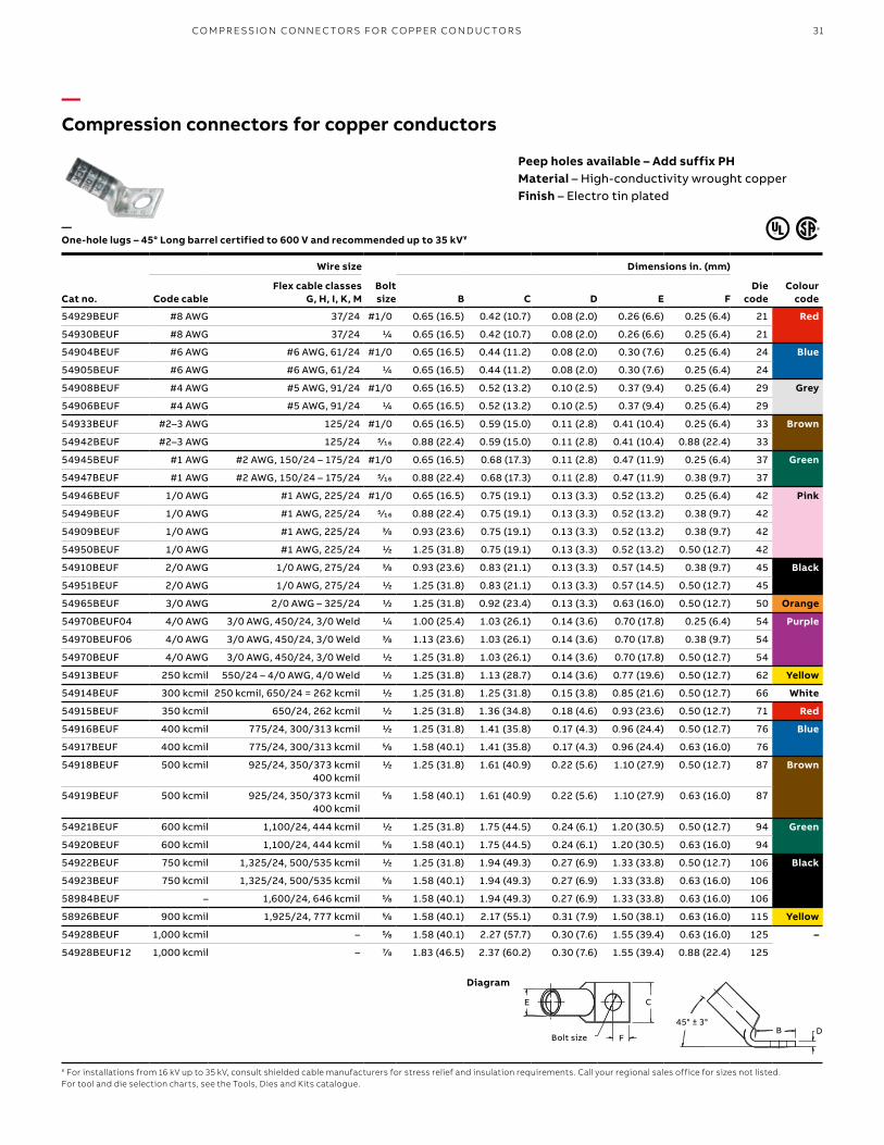
31
—Compression connectors for copper conductors
Cat no.
Wire size
Bolt size
Dimensions in. (mm)
Die code
Colour codeCode cable
Flex cable classes G, H, I, K, M B C D E F
54929BEUF #8 AWG 37/24 #1/0 0.65 (16.5) 0.42 (10.7) 0.08 (2.0) 0.26 (6.6) 0.25 (6.4) 21 Red
54930BEUF #8 AWG 37/24 1/4 0.65 (16.5) 0.42 (10.7) 0.08 (2.0) 0.26 (6.6) 0.25 (6.4) 21
54904BEUF #6 AWG #6 AWG, 61/24 #1/0 0.65 (16.5) 0.44 (11.2) 0.08 (2.0) 0.30 (7.6) 0.25 (6.4) 24 Blue
54905BEUF #6 AWG #6 AWG, 61/24 1/4 0.65 (16.5) 0.44 (11.2) 0.08 (2.0) 0.30 (7.6) 0.25 (6.4) 24
54908BEUF #4 AWG #5 AWG, 91/24 #1/0 0.65 (16.5) 0.52 (13.2) 0.10 (2.5) 0.37 (9.4) 0.25 (6.4) 29 Grey
54906BEUF #4 AWG #5 AWG, 91/24 1/4 0.65 (16.5) 0.52 (13.2) 0.10 (2.5) 0.37 (9.4) 0.25 (6.4) 29
54933BEUF #2–3 AWG 125/24 #1/0 0.65 (16.5) 0.59 (15.0) 0.11 (2.8) 0.41 (10.4) 0.25 (6.4) 33 Brown
54942BEUF #2–3 AWG 125/24 5⁄16 0.88 (22.4) 0.59 (15.0) 0.11 (2.8) 0.41 (10.4) 0.88 (22.4) 33
54945BEUF #1 AWG #2 AWG, 150/24 – 175/24 #1/0 0.65 (16.5) 0.68 (17.3) 0.11 (2.8) 0.47 (11.9) 0.25 (6.4) 37 Green
54947BEUF #1 AWG #2 AWG, 150/24 – 175/24 5⁄16 0.88 (22.4) 0.68 (17.3) 0.11 (2.8) 0.47 (11.9) 0.38 (9.7) 37
54946BEUF 1/0 AWG #1 AWG, 225/24 #1/0 0.65 (16.5) 0.75 (19.1) 0.13 (3.3) 0.52 (13.2) 0.25 (6.4) 42 Pink
54949BEUF 1/0 AWG #1 AWG, 225/24 5⁄16 0.88 (22.4) 0.75 (19.1) 0.13 (3.3) 0.52 (13.2) 0.38 (9.7) 42
54909BEUF 1/0 AWG #1 AWG, 225/24 3/8 0.93 (23.6) 0.75 (19.1) 0.13 (3.3) 0.52 (13.2) 0.38 (9.7) 42
54950BEUF 1/0 AWG #1 AWG, 225/24 1/2 1.25 (31.8) 0.75 (19.1) 0.13 (3.3) 0.52 (13.2) 0.50 (12.7) 42
54910BEUF 2/0 AWG 1/0 AWG, 275/24 3/8 0.93 (23.6) 0.83 (21.1) 0.13 (3.3) 0.57 (14.5) 0.38 (9.7) 45 Black
54951BEUF 2/0 AWG 1/0 AWG, 275/24 1/2 1.25 (31.8) 0.83 (21.1) 0.13 (3.3) 0.57 (14.5) 0.50 (12.7) 45
54965BEUF 3/0 AWG 2/0 AWG – 325/24 1/2 1.25 (31.8) 0.92 (23.4) 0.13 (3.3) 0.63 (16.0) 0.50 (12.7) 50 Orange
54970BEUF04 4/0 AWG 3/0 AWG, 450/24, 3/0 Weld 1/4 1.00 (25.4) 1.03 (26.1) 0.14 (3.6) 0.70 (17.8) 0.25 (6.4) 54 Purple
54970BEUF06 4/0 AWG 3/0 AWG, 450/24, 3/0 Weld 3/8 1.13 (23.6) 1.03 (26.1) 0.14 (3.6) 0.70 (17.8) 0.38 (9.7) 54
54970BEUF 4/0 AWG 3/0 AWG, 450/24, 3/0 Weld 1/2 1.25 (31.8) 1.03 (26.1) 0.14 (3.6) 0.70 (17.8) 0.50 (12.7) 54
54913BEUF 250 kcmil 550/24 – 4/0 AWG, 4/0 Weld 1/2 1.25 (31.8) 1.13 (28.7) 0.14 (3.6) 0.77 (19.6) 0.50 (12.7) 62 Yellow
54914BEUF 300 kcmil 250 kcmil, 650/24 = 262 kcmil 1/2 1.25 (31.8) 1.25 (31.8) 0.15 (3.8) 0.85 (21.6) 0.50 (12.7) 66 White
54915BEUF 350 kcmil 650/24, 262 kcmil 1/2 1.25 (31.8) 1.36 (34.8) 0.18 (4.6) 0.93 (23.6) 0.50 (12.7) 71 Red
54916BEUF 400 kcmil 775/24, 300/313 kcmil 1/2 1.25 (31.8) 1.41 (35.8) 0.17 (4.3) 0.96 (24.4) 0.50 (12.7) 76 Blue
54917BEUF 400 kcmil 775/24, 300/313 kcmil 5/8 1.58 (40.1) 1.41 (35.8) 0.17 (4.3) 0.96 (24.4) 0.63 (16.0) 76
54918BEUF 500 kcmil 925/24, 350/373 kcmil400 kcmil
1/2 1.25 (31.8) 1.61 (40.9) 0.22 (5.6) 1.10 (27.9) 0.50 (12.7) 87 Brown
54919BEUF 500 kcmil 925/24, 350/373 kcmil400 kcmil
5/8 1.58 (40.1) 1.61 (40.9) 0.22 (5.6) 1.10 (27.9) 0.63 (16.0) 87
54921BEUF 600 kcmil 1,100/24, 444 kcmil 1/2 1.25 (31.8) 1.75 (44.5) 0.24 (6.1) 1.20 (30.5) 0.50 (12.7) 94 Green
54920BEUF 600 kcmil 1,100/24, 444 kcmil 5/8 1.58 (40.1) 1.75 (44.5) 0.24 (6.1) 1.20 (30.5) 0.63 (16.0) 94
54922BEUF 750 kcmil 1,325/24, 500/535 kcmil 1/2 1.25 (31.8) 1.94 (49.3) 0.27 (6.9) 1.33 (33.8) 0.50 (12.7) 106 Black
54923BEUF 750 kcmil 1,325/24, 500/535 kcmil 5/8 1.58 (40.1) 1.94 (49.3) 0.27 (6.9) 1.33 (33.8) 0.63 (16.0) 106
58984BEUF – 1,600/24, 646 kcmil 5/8 1.58 (40.1) 1.94 (49.3) 0.27 (6.9) 1.33 (33.8) 0.63 (16.0) 106
58926BEUF 900 kcmil 1,925/24, 777 kcmil 5/8 1.58 (40.1) 2.17 (55.1) 0.31 (7.9) 1.50 (38.1) 0.63 (16.0) 115 Yellow
54928BEUF 1,000 kcmil – 5/8 1.58 (40.1) 2.27 (57.7) 0.30 (7.6) 1.55 (39.4) 0.63 (16.0) 125 –
54928BEUF12 1,000 kcmil – 7/8 1.83 (46.5) 2.37 (60.2) 0.30 (7.6) 1.55 (39.4) 0.88 (22.4) 125
—One-hole lugs – 45° Long barrel certified to 600 V and recommended up to 35 kV¥
¥ For installations from 16 kV up to 35 kV, consult shielded cable manufacturers for stress relief and insulation requirements. Call your regional sales office for sizes not listed.For tool and die selection charts, see the Tools, Dies and Kits catalogue.
Peep holes available – Add suffix PHMaterial – High-conductivity wrought copperFinish – Electro tin plated
Diagram
45° ± 3 °DBBolt size
E
F
C
DB45° ± 3°
E
FBolt size
C
CO M PR E SSI O N CO N N EC TO R S FO R CO PPER CO N D U C TO R S

B1 copy starts here
B2 copy starts here
B3 copy starts here
32 CO LO R- K E Y E D CO M PR E SSI O N CO N N EC TO R S Y S TEM
—Compression connectors for copper conductors
Cat no.
Wire size
Bolt size
Dimensions in. (mm)
Die code
Colour codeCode cable
Flex cable classes G, H, I, K, M B C D E F
54929BEUB #8 AWG 37/24 #10 0.65 (16.5) 0.42 (10.7) 0.08 (2.0) 0.26 (6.6) 0.25 (6.4) 21 Red
54930BEUB #8 AWG 37/24 1/4 0.65 (16.5) 0.42 (10.7) 0.08 (2.0) 0.26 (6.6) 0.25 (6.4) 21
54904BEUB #6 AWG #6 AWG, 61/24 #10 0.65 (16.5) 0.44 (11.2) 0.08 (2.0) 0.30 (7.6) 0.25 (6.4) 24 Blue
54905BEUB #6 AWG #6 AWG, 61/24 1/4 0.65 (16.5) 0.44 (11.2) 0.08 (2.0) 0.30 (7.6) 0.25 (6.4) 24
54908BEUB #4 AWG #5 AWG, 91/24 #10 0.65 (16.5) 0.52 (13.2) 0.10 (2.5) 0.37 (9.4) 0.25 (6.4) 29 Grey
54806BEUB #4 AWG #5 AWG, 91/24 1/4 0.65 (16.5) 0.52 (13.2) 0.10 (2.5) 0.37 (9.4) 0.25 (6.4) 29
54933BEUB #2–3 AWG 125/24 #10 0.65 (16.5) 0.59 (15.0) 0.11 (2.8) 0.41 (10.4) 0.25 (6.4) 33 Brown
54942BEUB #2–3 AWG 125/24 5⁄16 0.88 (22.4) 0.59 (15.0) 0.11 (2.8) 0.41 (10.4) 0.38 (9.7) 33
54945BEUB #1 AWG #2 AWG, 150/24 – 175/24 #10 0.65 (16.5) 0.68 (17.3) 0.11 (2.8) 0.47 (11.9) 0.25 (6.4) 37 Green
54947BEUB #1 AWG #2 AWG, 150/24 – 175/24 5⁄16 0.88 (22.4) 0.68 (17.3) 0.11 (2.8) 0.47 (11.9) 0.38 (9.7) 37
54946BEUB 1/0 AWG #1 AWG, 225/24 #10 0.65 (16.5) 0.75 (19.1) 0.13 (3.3) 0.52 (13.2) 0.25 (6.4) 42 Pink
54949BEUB 1/0 AWG #1 AWG, 225/24 5⁄16 0.88 (22.4) 0.75 (19.1) 0.13 (3.3) 0.52 (13.2) 0.38 (9.7) 42
54909BEUB 1/0 AWG #1 AWG, 225/24 3/8 0.93 (23.6) 0.75 (19.1) 0.13 (3.3) 0.52 (13.2) 0.38 (9.7) 42
54950BEUB 1/0 AWG #1 AWG, 225/24 1/2 1.25 (31.8) 0.75 (19.1) 0.13 (3.3) 0.52 (13.2) 0.50 (12.7) 42
54910BEUB 2/0 AWG 1/0 AWG, 275/24 3/8 0.93 (23.6) 0.83 (21.1) 0.13 (3.3) 0.57 (14.5) 0.38 (9.7) 45 Black
54951BEUB 2/0 AWG 1/0 AWG, 275/24 1/2 1.25 (31.8) 0.83 (21.1) 0.13 (3.3) 0.57 (14.5) 0.50 (12.7) 45
54965BEUB 3/0 AWG 2/0 AWG – 325/24 1/2 1.25 (31.8) 0.92 (23.4) 0.13 (3.3) 0.63 (16.0) 0.50 (12.7) 50 Orange
54970BEUB04 4/0 AWG 3/0 AWG, 450/24, 3/0 Weld 1/4 1.00 (25.4) 1.03 (26.2) 0.14 (3.6) 0.70 (17.8) 0.25 (6.4) 54 Purple
54970BEUB06 4/0 AWG 3/0 AWG, 450/24, 3/0 Weld 3/8 1.13 (28.7) 1.03 (26.2) 0.14 (3.6) 0.70 (17.8) 0.38 (9.7) 54
54970BEUB 4/0 AWG 3/0 AWG, 450/24, 3/0 Weld 1/2 1.25 (31.8) 1.03 (26.2) 0.14 (3.6) 0.70 (17.8) 0.50 (12.7) 54
54913BEUB 250 kcmil 550/24 – 4/0 AWG, 4/0 Weld 1/2 1.25 (31.8) 1.13 (28.7) 0.14 (3.6) 0.77 (19.6) 0.50 (12.7) 62 Yellow
54914BEUB 300 kcmil 250 kcmil, 650/24 = 262 kcmil 1/2 1.25 (31.8) 1.25 (31.8) 0.15 (3.8) 0.85 (21.6) 0.50 (12.7) 66 White
54915BEUB 350 kcmil 650/24, 262 kcmil 1/2 1.25 (31.8) 1.36 (34.5) 0.18 (4.6) 0.93 (23.6) 0.50 (12.7) 71 Red
54916BEUB 400 kcmil 775/24, 300/313 kcmil 1/2 1.58 (40.1) 1.41 (35.8) 0.17 (4.3) 0.96 (24.4) 0.50 (12.7) 76 Blue
54917BEUB 400 kcmil 775/24, 300/313 kcmil 5/8 1.25 (31.8) 1.41 (35.8) 0.17 (4.3) 0.96 (24.4) 0.63 (16.0) 76
54918BEUB 500 kcmil 925/24, 350/373 kcmil, 400 kcmil 1/2 1.58 (40.1) 1.61 (40.9) 0.22 (5.6) 1.10 (27.9) 0.50 (12.7) 87 Brown
54919BEUB 500 kcmil 925/24, 350/373 kcmil, 400 kcmil 5/8 1.25 (31.8) 1.61 (40.9) 0.22 (5.6) 1.10 (27.9) 0.63 (16.0) 87
54921BEUB 600 kcmil 1100/24, 444 kcmil 1/2 1.58 (40.1) 1.75 (44.5) 0.24 (6.1) 1.20 (30.5) 0.50 (12.7) 94 Green
54920BEUB 600 kcmil 1100/24, 444 kcmil 5/8 1.25 (31.8) 1.75 (44.5) 0.24 (6.1) 1.20 (30.5) 0.63 (16.0) 94
54922BEUB 750 kcmil 1,325/24, 500/535 kcmil 1/2 1.25 (31.8) 1.94 (49.3) 0.27 (6.9) 1.33 (33.8) 0.50 (12.7) 106 Black
54923BEUB 750 kcmil 1,325/24, 500/535 kcmil 5/8 1.58 (40.1) 1.94 (49.3) 0.27 (6.9) 1.33 (33.8) 0.63 (16.0) 106
58984BEUB – 1,600/24, 646 kcmil 5/8 1.58 (40.1) 1.94 (49.3) 0.27 (6.9) 1.33 (33.8) 0.63 (16.0) 106
58926BEUB 900 kcmil 1,925/24, 777 kcmil 5/8 1.58 (40.1) 2.17 (55.1) 0.31 (7.9) 1.50 (38.1) 0.63 (16.0) 115 Yellow
54928BEUB 1,000 kcmil – 5/8 1.58 (40.1) 2.27 (57.7) 0.30 (7.6) 1.55 (39.4) 0.63 (16.0) 125 –
54928BEUB12 1,000 kcmil – 7/8 1.58 (46.5) 2.37 (60.2) 0.30 (7.6) 1.55 (39.4) 0.88 (22.4) 125
—One-hole lugs – 90° Long barrel certified to 600 V and recommended up to 35 kV¥
¥ For installations from 16 kV up to 35 kV, consult shielded cable manufacturers for stress relief and insulation requirements. Call your regional sales office for sizes not listed.For tool and die selection charts, see the Tools, Dies and Kits catalogue.
Peep holes available – Add suffix PHMaterial – High-conductivity wrought copperFinish – Electro tin plated
Bolt Size
90° ± 3 ° B
D
C
E F
Diagram
E
C
FBolt size
D
B90° ± 3°

33
—Compression connectors for copper conductors
Peep holes available – Add suffix PHMaterial – High-conductivity wrought copperFinish – Electro tin plated
Cat no.
Wire size
Bolt size
Dimensions in. (mm)
Die code
Colour codeCode cable
Flex cable classes
G, H, I, K, M A B C D E F H
54801BE #14–10 AWG – 1/4 1.86 (47.2) 1.19 (30.2) 0.50 (12.7) 0.05 (1.3) 0.20 (5.1) 0.25 (6.4) 0.63 (16.0) ERG4002 Yellow
256-31426-3 #14–10 AWG #10 2.00 (50.8) 1.25 (31.2) 0.37 (9.4) 0.07 (1.8) 0.20 (5.1) 0.25 (6.4) 0.63 (16.0) ERG4002
256-31426-3SPH #14–10 AWG #10 2.00 (50.8) 1.25 (31.2) 0.37 (9.4) 0.07 (1.8) 0.20 (5.1) 0.22 (5.6) 0.63 – 0.75 (16.0) – (19.1)
ERG4002
256-30695-1298 #14–10 AWG 1/4 1.89 (48.0) 1.22 (31.0) 0.50 (12.7) 0.05 (1.3) 0.20 (5.1) 0.25 (6.4) 0.63 (16.0) ERG4002
256-30695-1730 #14–10 AWG 1/4 1.98 (50.3) 1.31 (33.3) 0.50 (12.7) 0.05 (1.3) 0.20 (5.1) 0.25 (6.4) 0.63 – 0.75 (16.0) – (19.1)
ERG4002
54850BE #8 AWG #8 AWG, #8 Weld
37/24
1/4 2.19 (55.6) 1.89 (48.0) 0.42 (10.7) 0.07 (1.78) 0.26 (6.6) 0.25 (6.4) 0.63 (16.0) 21 Red
54851BE #8 AWG 1/4 2.31 (58.7) 1.29 (32.8) 0.47 (11.9) 0.06 (1.52) 0.26 (6.6) 0.25 (6.4) 0.75 (19.1) 21
256-30695-1157 #8 AWG 3/8 3.00 (76.2) 2.10 (53.3) 0.56 (14.2) 0.06 (1.52) 0.26 (6.6) 0.38 (9.7) 1.00 (25.4) 21
54852BE #6 AWG #6 AWG, 61/24,
#6 Weld
1/4 2.28 (57.9) 1.28 (32.5) 0.44 (11.1) 0.08 (2.03) 0.30 (7.6) 0.25 (6.4) 0.63 (16.0) 24 Blue
256-30695-1014 #6 AWG 1/4 2.63 (66.8) 1.63 (41.4) 0.43 (10.9) 0.08 (2.03) 0.30 (7.6) 0.25 (6.4) 1.00 (25.4) 24
256-30695-1225 #6 AWG 1/4 2.43 (61.7) 1.43 (36.3) 0.43 (10.9) 0.08 (2.03) 0.30 (7.6) 0.25 (6.4) 0.75 (19.1) 24
256-30695-1158 #6 AWG 3/8 2.93 (74.4) 1.93 (49.0) 0.59 (14.9) 0.06 (1.52) 0.30 (7.6) 0.38 (9.7) 1.00 (25.4) 24
256-30695-868 #6 AWG 1/2 4.18 (106.2) 3.00 (76.2) 0.88 (22.4) 0.11 (2.8) 0.30 (7.6) 0.50 (12.7) 1.75 (44.5) 24
54854BE #4 AWG 91/24, #5 AWG, #4 Weld
1/4 2.31 (58.7) 1.19 (30.2) 0.52 (13.1) 0.10 (2.5) 0.37 (9.4) 0.25 (6.4) 0.63 (16.0) 29 Grey
256-30695-1246 #4 AWG 1/4 2.31 (54.1) 1.31 (33.3) 0.56 (14.2) 0.09 (2.3) 0.37 (9.4) 0.25 (6.4) 0.75 (19.1) 29
256-30695-1015 #4 AWG 1/4 2.88 (73.2) 1.88 (47.8) 0.58 (14.7) 0.09 (2.3) 0.37 (9.4) 0.38 (9.7) 1.00 (25.4) 29
256-30695-1337 #4 AWG 5⁄16 2.75 (69.9) 1.75 (44.5) 0.56 (14.2) 0.10 (2.5) 0.37 (9.4) 0.34 (8.4) 1.00 (25.4) 29
256-30695-1159 #4 AWG 3/8 3.13 (79.5) 1.98 (50.3) 0.59 (14.9) 0.09 (2.3) 0.37 (9.4) 0.38 (9.7) 1.00 (25.4) 29
256-30695-733 #4 AWG 1/2 4.18 (106.2) 3.00 (76.2) 0.88 (22.4) 0.09 (2.3) 0.37 (9.4) 0.50 (12.7) 1.75 (44.5) 29
256-30695-1016* #2–3 AWG #3 AWG, 125/24
1/4 3.06 (77.7) 1.88 (47.8) 0.67 (17.0) 0.09 (2.3) 0.41 (10.4) 0.38 (9.7) 1.00 (25.4) 33 Brown
54855BE #2–3 AWG 1/4 2.43 (61.7) 1.28 (32.5) 0.59 (14.9) 0.11 (2.8) 0.41 (10.4) 0.50 (12.7) 0.63 (16.0) 33
256-30695-1300 #2–3 AWG 1/4 2.63 (66.8) 1.35 (34.3) 0.68 (17.3) 0.11 (2.8) 0.41 (10.4) 0.25 (6.4) 0.75 (19.1) 33
54856BE #2–3 AWG 5⁄16 2.78 (70.6) 1.63 (41.4) 0.59 (14.9) 0.11 (2.8) 0.41 (10.4) 0.38 (9.7) 0.75 (19.1) 33
54810BE #2–3 AWG 3/8 3.80 (96.5) 2.57 (65.3) 0.59 (14.9) 0.11 (2.8) 0.41 (10.4) 0.38 (9.7) 1.75 (44.5) 33
256-30695-1160 #2–3 AWG 3/8 3.08 (78.2) 1.94 (49.3) 0.59 (14.9) 0.11 (2.8) 0.41 (10.4) 0.38 (9.7) 1.00 (25.4) 33
256-30695-869 #2–3 AWG 1/2 4.02 (102.1) 2.88 (73.2) 0.25 (6.4) 0.75 (19.1) 0.41 (10.4) 0.63 (16.0) 1.75 (44.5) 33
54811BE #2–3 AWG 1/2 4.28 (108.7) 3.00 (76.2) 0.88 (22.4) 0.11 (2.8) 0.41 (10.4) 0.50 (12.7) 1.75 (44.5) 33
54809BE #1 AWG #2 AWG150/24175/24
#2 Weld
1/4 2.88 (73.2) 1.19 (30.2) 0.67 (17.0) 0.11 (2.8) 0.47 (11.9) 0.25 (6.4) 0.63 (16.0) 37 Green
54812BE #1 AWG 1/4 2.75 (69.9) 1.40 (35.6) 0.67 (17.0) 0.11 (2.8) 0.47 (11.9) 0.25 (6.4) 0.75 (19.1) 37
54858BE #1 AWG 5⁄16 2.94 (75.4) 1.63 (41.4) 0.67 (17.0) 0.11 (2.8) 0.47 (11.9) 0.38 (9.7) 0.88 (22.4) 37
256-30695-1161 #1 AWG 3/8 3.30 (83.8) 1.98 (50.3) 0.67 (17.0) 0.11 (2.8) 0.47 (11.9) 0.38 (9.7) 1.00 (25.4) 37
54857BE #1 AWG 1/2 4.43 (112.5) 3.00 (76.2) 0.88 (22.4) 0.11 (2.8) 0.47 (11.9) 0.50 (12.7) 1.75 (44.5) 37
—Two-hole lugs – Long barrel certified to 600 V and recommended up to 35 kV¥
* CSA not applicable¥ For installations from 16 kV up to 35 kV, consult shielded cable manufacturers for stress relief and insulation requirements. Call your regional sales office for sizes not listed.For tool and die selection charts, see the Tools, Dies and Kits catalogue.
Diagram
A
EC
D
B
H F
C
FH
A
B
D
E
CO M PR E SSI O N CO N N EC TO R S FO R CO PPER CO N D U C TO R S

B1 copy starts here
B2 copy starts here
B3 copy starts here
34 CO LO R- K E Y E D CO M PR E SSI O N CO N N EC TO R S Y S TEM
—Compression connectors for copper conductors
Peep holes available – Add suffix PHMaterial – High-conductivity wrought copperFinish – Electro tin plated
Cat no.
Wire size
Bolt size
Dimensions in. (mm)
Die code
Colour code
Code cable
Flex cable classes
G, H, I, K, M A B C D E F H
256-30695-1018 1/0 AWG #1 AWG, 225/24
1/4 3.63 (92.2) 1.88 (47.8) 0.75 (19.0) 0.13 (3.3) 0.52 (13.2) 0.38 (9.7) 1.00 (25.4) 42 Pink
256-30695-1018P 1/0 AWG 1/4 3.63 (92.2) 1.88 (47.8) 0.75 (19.0) 0.13 (3.3) 0.52 (13.2) 0.38 (9.7) 1.00 (25.4) 42
54859BE 1/0 AWG 1/4 2.63 (66.8) 1.19 (30.2) 0.75 (19.0) 0.13 (3.3) 0.52 (13.2) 0.25 (6.4) 0.63 (16.0) 42
54813BE 1/0 AWG 1/4 2.71 (68.8) 1.38 (35.1) 0.75 (19.0) 0.13 (3.3) 0.52 (13.2) 0.25 (6.4) 0.75 (19.1) 42
54860BE 1/0 AWG 5⁄16 2.97 (75.4) 1.63 (41.4) 0.75 (19.0) 0.13 (3.3) 0.52 (13.2) 0.50 (12.7) 0.88 (22.4) 42
256-30695-1162P 1/0 AWG 3/8 3.25 (82.3) 1.98 (50.3) 0.75 (19.0) 0.13 (3.3) 0.52 (13.2) 0.38 (9.7) 1.00 (25.4) 42
256-30695-1162 1/0 AWG 3/8 3.23 (82.0) 1.93 (49.0) 0.75 (19.0) 0.13 (3.3) 0.52 (13.2) 0.38 (9.7) 1.00 (25.4) 42
256-30695-593 1/0 AWG 1/2 4.33 (110.0) 3.00 (76.2) 0.75 (19.0) 0.13 (3.3) 0.52 (13.2) 0.63 (16.0) 1.75 (44.5) 42
54814BE 2/0 AWG 1/0 AWG, 1/0 Weld
275/24
1/4 2.62 (66.5) 1.25 (31.8) 0.83 (21.1) 0.13 (3.3) 0.57 (14.5) 0.25 (6.4) 0.63 (16.0) 45 Black
256-30695-1299 2/0 AWG 1/4 2.69 (68.3) 1.31 (33.3) 0.81 (20.6) 0.13 (3.3) 0.57 (14.5) 0.25 (6.4) 0.75 (19.1) 45
256-30695-1116 2/0 AWG 3/8 3.19 (81.0) 1.81 (46.0) 0.83 (21.1) 0.13 (3.3) 0.57 (14.5) 0.38 (9.7) 1.00 (25.4) 45
256-30695-1116P 2/0 AWG 3/8 3.19 (81.0) 1.81 (46.0) 0.83 (21.1) 0.13 (3.3) 0.57 (14.5) 0.38 (9.7) 1.00 (25.4) 45
54862BE 2/0 AWG 1/2 4.20 (106.7) 2.81 (71.4) 0.83 (21.1) 0.13 (3.3) 0.57 (14.5) 0.50 (12.7) 1.75 (44.5) 45
54815BE 3/0 AWG 2/0 AWG, 2/0 Weld
325/24
1/4 2.89 (73.4) 1.45 (36.8) 0.92 (23.4) 0.13 (3.3) 0.63 (16.0) 0.25 (6.4) 0.75 (19.1) 50 Orange
54816BE 3/0 AWG 3/8 3.25 (82.6) 1.63 (41.4) 0.92 (23.4) 0.13 (3.3) 0.63 (16.0) 0.38 (9.7) 1.00 (25.4) 50
54864BE 3/0 AWG 1/2 4.48 (113.8) 3.00 (76.2) 0.94 (23.9) 0.13 (3.3) 0.63 (16.0) 0.50 (12.7) 1.75 (44.5) 50
54817BE 4/0 AWG 3/0 AWG, 3/0 Weld
450/24
1/4 3.15 (80.0) 1.38 (35.1) 1.03 (33.0) 0.14 (3.6) 0.70 (17.8) 0.25 (6.4) 0.75 (19.1) 54 Purple
54818BE 4/0 AWG 3/8 4.38 (111.3) 2.63 (66.8) 1.03 (33.0) 0.14 (3.6) 0.70 (17.8) 0.38 (9.7) 1.75 (44.5) 54
256-30695-1117 4/0 AWG 3/8 3.35 (85.1) 1.81 (46.0) 1.03 (33.0) 0.14 (3.6) 0.70 (17.8) 0.38 (9.7) 1.00 (25.4) 54
256-30695-1117P 4/0 AWG 3/8 3.50 (88.9) 1.88 (47.8) 1.03 (33.0) 0.14 (3.6) 0.70 (17.8) 0.38 (9.7) 1.00 (25.4) 54
54866BE 4/0 AWG 1/2 4.70 (119.4) 3.00 (76.2) 1.03 (33.0) 0.14 (3.6) 0.70 (17.8) 0.50 (12.7) 1.75 (44.5) 54
256-30695-1245 250 kcmil 4/0 AWG, 4/0 Weld
550/24
3/8 3.83 (97.3) 1.93 (49.0) 1.13 (28.7) 0.14 (3.6) 0.77 (19.6) 0.38 (9.7) 1.00 (25.4) 62 Yellow
256-30695-1245P 250 kcmil 3/8 3.83 (97.3) 1.93 (49.0) 1.13 (28.7) 0.14 (3.6) 0.77 (19.6) 0.38 (9.7) 1.00 (25.4) 62
54868BE 250 kcmil 1/2 4.92 (125.0) 3.00 (76.2) 1.13 (28.7) 0.14 (3.6) 0.77 (19.6) 0.50 (12.7) 1.75 (44.5) 62
54819BE 300 kcmil 250 kcmil650/24 = 262 kcmil
3/8 5.04 (137.2) 2.80 (71.1) 1.25 (31.8) 0.15 (3.8) 0.85 (21.6) 0.38 (9.7) 1.00 (25.4) 66 White
54870BE 300 kcmil 1/2 5.23 (132.8) 3.00 (76.2) 1.25 (31.8) 0.15 (3.8) 0.85 (21.6) 0.50 (12.7) 1.75 (44.5) 66
54820BE 350 kcmil – 1/4 4.29 (109.0) 1.93 (49.0) 1.36 (34.5) 0.18 (4.6) 0.93 (23.6) 0.25 (6.4) 1.75 (44.5) 71 Red
256-30695-1118 350 kcmil 3/8 4.33 (110.0) 1.93 (49.0) 1.36 (34.5) 0.18 (4.6) 0.93 (23.6) 0.38 (9.7) 1.00 (25.4) 71
256-30695-1118P 350 kcmil 3/8 4.33 (110.0) 1.93 (49.0) 1.36 (34.5) 0.18 (4.6) 0.93 (23.6) 0.38 (9.7) 1.00 (25.4) 71
54872BE 350 kcmil 1/2 5.40 (137.2) 3.00 (76.2) 1.36 (34.5) 0.18 (4.6) 0.93 (23.6) 0.50 (12.7) 1.75 (44.5) 71
—Two-hole lugs – Long barrel certified to 600 V and recommended up to 35 kV¥ (continued)
¥ For installations from 16 kV up to 35 kV, consult shielded cable manufacturers for stress relief and insulation requirements. Call your regional sales office for sizes not listed.For tool and die selection charts, see the Tools, Dies and Kits catalogue.
Diagram
A
EC
D
B
H F
C
FH
A
B
D
E

35
—Compression connectors for copper conductors
Peep holes available – Add suffix PHMaterial – High-conductivity wrought copperFinish – Electro tin plated
Cat no.
Wire size
Bolt size
Dimensions in. (mm)
Die code
Colour code
Code cable
Flex cable classes G, H, I, K, M A B C D E F H
54822BE 400 kcmil 300 kcmil775/24,
313 kcmil
1/4 4.38 (111.3) 1.93 (49.0) 1.41 (35.8) 0.17 (4.3) 0.96 (24.4) 0.25 (6.4) 0.75 (19.1) 76 Blue
54821BE 400 kcmil 3/8 4.43 (112.5) 1.93 (49.0) 1.41 (35.8) 0.17 (4.3) 0.96 (24.4) 0.38 (9.7) 1.00 (25.4) 76
54874BE 400 kcmil 1/2 5.51 (140.0) 3.00 (76.2) 1.41 (35.8) 0.17 (4.3) 0.96 (24.4) 0.50 (12.7) 1.75 (44.5) 76
54823BE 500 kcmil 400 kcmil925/24
350/373 kcmil
1/4 4.93 (125.2) 1.94 (49.3) 1.61 (40.9) 0.22 (5.6) 1.10 (27.9) 0.25 (6.4) 0.75 (19.1) 87 Brown
256-30695-1119 500 kcmil 3/8 5.00 (127.0) 1.93 (49.0) 1.61 (40.9) 0.22 (5.6) 1.10 (27.9) 0.38 (9.7) 1.00 (25.4) 87
256-30695-1119P 500 kcmil 3/8 5.00 (127.0 1.93 (49.0) 1.61 (40.9) 0.22 (5.6) 1.10 (27.9) 0.38 (9.7) 1.00 (25.4) 87
54876BE 500 kcmil 1/2 6.00 (152.4) 3.00 (76.2) 1.61 (40.9) 0.22 (5.6) 1.10 (27.9) 0.50 (12.7) 1.75 (44.5) 87
54824BE 600 kcmil 1100/24, 444 kcmil
3/8 5.70 (144.8) 2.80 (71.1) 1.75 (44.5) 0.24 (6.1) 1.20 (30.5) 0.38 (9.7) 1.00 (25.4) 94 Green
54878BE 600 kcmil 1/2 5.83 (148.1) 3.00 (76.2) 1.75 (44.5) 0.24 (6.1) 1.20 (30.5) 0.50 (12.7) 1.75 (44.5) 94
54879BE 700 kcmil 1,325/24, 535 kcmil 1/2 5.83 (148.1) 3.00 (76.2) 1.80 (45.7) 0.24 (6.1) 1.25 (31.8) 0.50 (12.7) 1.75 (44.5) 99 Pink
256-30695-1222 750 kcmil 1325/24, 535 kcmil
3/8 5.25 (133.4) 2.06 (52.3) 1.94 (49.3) 0.27 (6.7) 1.33 (33.8) 0.50 (12.7) 1.00 (25.4) 106 Black
256-30695-1222P 750 kcmil 3/8 5.25 (133.4) 2.06 (52.3) 1.94 (49.3) 0.27 (6.7) 1.33 (33.8) 0.50 (12.7) 1.00 (25.4) 106
54880BE 750 kcmil 1/2 6.20 (157.5) 3.00 (76.2) 1.94 (49.3) 0.27 (6.9) 1.33 (33.8) 0.50 (12.7) 1.75 (44.5) 106
58884BE – 1,600/24, 646 kcmil 1/2 6.16 (156.5) 3.00 (76.2) 1.94 (49.3) 0.27 (6.9) 1.33 (33.8) 0.50 (12.7) 1.75 (44.5) 106
58826BE 900 kcmil 1,925/24, 777 kcmil 1/2 6.74 (171.2) 3.00 (76.2) 2.18 (55.4) 0.31 (7.9) 1.50 (38.1) 0.50 (12.7) 1.75 (44.5) 115 Yellow
54826BE 1,000 kcmil – 3/8 6.49 (164.8) 2.80 (71.1) 2.27 (57.7) 0.30 (7.6) 1.55 (39.4) 0.38 (9.7) 1.00 (25.4) 125 –
54882BE 1,000 kcmil 1/2 6.66 (169.2) 3.00 (76.2) 2.27 (57.7) 0.30 (7.6) 1.55 (39.4) 0.38 (9.7) 1.75 (44.5) 125
54888BE 1,250 kcmil 1/2 7.88 (200.2) 3.00 (76.2) 2.42 (61.5) 0.35 (8.9) 1.67 (42.4) 0.63 (16.0) 1.75 (44.5) 140
—Two-hole lugs – Long barrel certified to 600 V and recommended up to 35 kV¥ (continued)
¥ For installations from 16 kV up to 35 kV, consult shielded cable manufacturers for stress relief and insulation requirements. Call your regional sales office for sizes not listed.For tool and die selection charts, see the Tools, Dies and Kits catalogue.
Diagram
A
EC
D
B
H F
C
FH
A
B
D
E
CO M PR E SSI O N CO N N EC TO R S FO R CO PPER CO N D U C TO R S

B1 copy starts here
B2 copy starts here
B3 copy starts here
36 CO LO R- K E Y E D CO M PR E SSI O N CO N N EC TO R S Y S TEM
—Compression connectors for copper conductors
Peep holes available – Add suffix PHMaterial – High-conductivity wrought copperFinish – Electro tin plated
Cat no.
Wire size
Bolt size
Dimensions in. (mm)
Die code
Colour codeCode cable
Flex cable classes
G, H, I, K, M B C D E F G
256-31426-3SPHUF #14–10 AWG – #10 1.25 (31.75) 0.37 (9.4) 0.07 (1.8) 0.20 (5.1) 0.22 (5.6) 0.50 – 0.63 (12.7 – 16.0)
ERG2002 Yellow
256-30695-1298UF #14–10 AWG 1/4 1.22 (31.0) 0.50 (12.7) 0.05 (1.3) 0.20 (5.1) 0.25 (6.4) 0.63 (16.0) ERG2002
54850BEUF #8 AWG #8 AWG37/24
#8 Weld
1/4 1.89 (48.0) 0.42 (10.7) 0.07 (17.8) 0.26 (6.6) 0.25 (6.4) 0.63 (16.0) 21 Red
54851BEUF #8 AWG 1/4 1.29 (32.8) 0.47 (11.9) 0.06 (15.2) 0.26 (6.6) 0.25 (6.4) 0.75 (19.1) 21
54851BEUF0612 #8 AWG 3/8 1.42 (36.1) 0.47 (11.9) 0.06 (15.2) 0.26 (6.6) 0.38 (9.7) 0.75 (19.1) 21
54852BEUF #6 AWG #6 AWG61/24
#6 Weld
1/4 1.28 (32.5) 0.44 (11.2) 0.08 (20.3) 0.30 (7.6) 0.25 (6.4) 0.63 (16.0) 24 Blue
54852BEUF0416 #6 AWG 1/4 1.63 (41.4) 0.43 (10.9) 0.08 (20.3) 0.30 (7.6) 0.25 (6.4) 1.00 (25.4) 24
54852BEUF0412 #6 AWG 1/4 1.43 (36.3) 0.43 (10.9) 0.08 (20.3) 0.30 (7.6) 0.25 (6.4) 0.75 (19.1) 24
54852BEUF0616 #6 AWG 3/8 1.93 (49.0) 0.59 (15.0) 0.06 (15.2) 0.30 (7.6) 0.38 (9.7) 1.00 (25.4) 24
54852BEUF0828 #6 AWG 1/2 3.00 (76.2) 0.88 (22.4) 0.11 (2.8) 0.30 (7.6) 0.50 (12.7) 1.75 (44.5) 24
54854BEUF #4 AWG #5 AWG91/24
#4 Weld
1/4 1.19 (30.2) 0.52 (13.2) 0.10 (2.5) 0.37 (9.4) 0.25 (6.4) 0.63 (16.0) 29 Grey
54854BEUF0412 #4 AWG 1/4 1.31 (33.3) 0.56 (14.2) 0.09 (2.3) 0.37 (9.4) 0.25 (6.4) 0.75 (19.1) 29
54854BEUF0416 #4 AWG 1/4 1.88 (47.8) 0.58 (14.7) 0.09 (2.3) 0.37 (9.4) 0.38 (9.7) 1.00 (25.4) 29
54854BEUF0516 #4 AWG 5⁄16 1.75 (44.5) 0.56 (14.2) 0.10 (2.5) 0.37 (9.4) 0.63 (16.0) 1.00 (25.4) 29
54854BEUF0616 #4 AWG 3/8 1.98 (50.3) 0.59 (15.0) 0.09 (2.3) 0.37 (9.4) 0.38 (9.7) 1.00 (25.4) 29
54854BEUF0828 #4 AWG 1/2 3.00 (76.2) 0.88 (22.4) 0.09 (2.3) 0.37 (9.4) 0.50 (12.7) 1.75 (44.5) 29
54855BEUF0416 #2–3 AWG #3 AWG125/24
1/4 1.88 (47.8) 0.67 (17.0) 0.09 (2.3) 0.41 (10.4) 0.38 (9.7) 1.00 (25.4) 33 Brown
54855BEUF #2–3 AWG 1/4 1.28 (32.5) 0.59 (15.0) 0.11 (2.8) 0.41 (10.4) 0.25 (6.4) 0.63 (16.0) 33
54855BEUF0412 #2–3 AWG 1/4 1.35 (34.3) 0.68 (17.3) 0.11 (2.8) 0.41 (10.4) 0.25 (6.4) 0.75 (19.1) 33
54856BEUF #2–3 AWG 5⁄16 1.63 (41.4) 0.59 (15.0) 0.11 (2.8) 0.41 (10.4) 0.38 (9.7) 0.75 (19.1) 33
54810BEUF #2–3 AWG 3/8 2.57 (65.3) 0.59 (15.0) 0.11 (2.8) 0.41 (10.4) 0.38 (9.7) 1.75 (44.5) 33
54810BEUF0616 #2–3 AWG 3/8 1.94 (49.3) 0.59 (15.0) 0.11 (2.8) 0.41 (10.4) 0.38 (9.7) 1.00 (25.4) 33
54811BEUF #2–3 AWG 1/2 3.00 (76.2) 0.88 (22.4) 0.11 (2.8) 0.41 (10.4) 0.50 (12.7) 1.75 (44.5) 33
54809BEUF #1 AWG #2 AWG150/24175/24
#2 Weld
1/4 1.19 (30.2) 0.67 (17.0) 0.11 (2.8) 0.47 (11.9) 0.25 (6.4) 0.63 (16.0) 37 Green
54812BEUF #1 AWG 1/4 1.40 (35.6) 0.67 (17.0) 0.11 (2.8) 0.47 (11.9) 0.25 (6.4) 0.75 (19.1) 37
54858BEUF #1 AWG 5⁄16 1.63 (41.4) 0.67 (17.0) 0.11 (2.8) 0.47 (11.9) 0.63 (16.0) 0.88 (22.4) 37
54857BEUF0616 #1 AWG 3/8 1.98 (50.3) 0.67 (17.0) 0.11 (2.8) 0.47 (11.9) 0.38 (9.7) 1.00 (25.4) 37
54857BEUF #1 AWG 1/2 3.00 (76.2) 0.88 (22.4) 0.11 (2.8) 0.47 (11.9) 0.50 (12.7) 1.75 (44.5) 37
—Two-hole lugs – 45° Long barrel certified to 600 V and recommended up to 35 kV¥
¥ For installations from 16 kV up to 35 kV, consult shielded cable manufacturers for stress relief and insulation requirements. Call your regional sales office for sizes not listed.For tool and die selection charts, see the Tools, Dies and Kits catalogue.
Diagram
Bolt Size
E C
FG
45° ± 3 °
DBFBolt size G
E C
B D45° ± 3°

37
—Compression connectors for copper conductors
Peep holes available – Add suffix PHMaterial – High-conductivity wrought copperFinish – Electro tin plated
Cat no.
Wire size
Bolt size
Dimensions in. (mm)
Die code
Colour codeCode cable
Flex cable classes G, H, I, K, M B C D E F G
54859BEUF0416 1/0 AWG 1 AWG225/24
1/4 1.88 (47.8) 0.75 (19.1) 0.13 (3.3) 0.52 (13.2) 0.38 (9.7) 1.00 (25.4) 42 Pink
54859BEUF0416PH 1/0 AWG 1/4 1.88 (47.8) 0.75 (19.1) 0.13 (3.3) 0.52 (13.2) 0.38 (9.7) 1.00 (25.4) 42
54859BEUF 1/0 AWG 1/4 1.19 (30.2) 0.75 (19.1) 0.13 (3.3) 0.52 (13.2) 0.25 (6.4) 0.38 (9.7) 42
54813BEUF 1/0 AWG 1/4 1.38 (35.1) 0.75 (19.1) 0.13 (3.3) 0.52 (13.2) 0.25 (6.4) 0.75 (19.1) 42
54860BEUF 1/0 AWG 5⁄16 1.63 (41.4) 0.75 (19.1) 0.13 (3.3) 0.52 (13.2) 0.38 (9.7) 0.88 (22.4) 42
54860BEUF0616 1/0 AWG 3/8 1.98 (50.3) 0.75 (19.1) 0.13 (3.3) 0.52 (13.2) 0.38 (9.7) 1.00 (25.4) 42
54860BEUF0616PH 1/0 AWG 3/8 1.93 (49.0) 0.75 (19.1) 0.13 (3.3) 0.52 (13.2) 0.38 (9.7) 1.00 (25.4) 42
54860BEUF0828 1/0 AWG 1/2 3.00 (76.0) 0.75 (19.1) 0.13 (3.3) 0.52 (13.2) 0.63 (16.0) 1.75 (44.5) 42
54814BEUF 2/0 AWG 1/0 AWG275/24
1/0 Weld
1/4 1.25 (31.8) 0.83 (21.1) 0.13 (3.3) 0.57 (14.5) 0.25 (6.4) 0.63 (16.0) 45 Black
54814BEUF0412 2/0 AWG 1/4 1.31 (33.3) 0.81 (20.6) 0.13 (3.3) 0.57 (14.5) 0.25 (6.4) 0.75 (19.1) 45
54862BEUF0616 2/0 AWG 3/8 1.81 (46.0) 0.83 (21.1) 0.13 (3.3) 0.57 (14.5) 0.38 (9.7) 1.00 (25.4) 45
54862BEUF0616PH 2/0 AWG 3/8 1.81 (46.0) 0.83 (21.1) 0.13 (3.3) 0.57 (14.5) 0.38 (9.7) 1.00 (25.4) 45
54862BEUF 2/0 AWG 1/2 2.81 (71.4) 0.83 (21.1) 0.13 (3.3) 0.57 (14.5) 0.50 (12.7) 1.75 (44.5) 45
54815BEUF 3/0 AWG 2/0 AWG325/24
2/0 Weld
1/4 1.45 (36.8) 0.92 (23.4) 0.13 (3.3) 0.63 (16.0) 0.25 (6.4) 0.75 (19.1) 50 Orange
54816BEUF 3/0 AWG 3/8 0.63 (41.4) 0.92 (23.4) 0.13 (3.3) 0.63 (16.0) 0.38 (9.7) 1.00 (25.4) 50
54864BEUF 3/0 AWG 1/2 3.00 (76.2) 0.94 (23.9) 0.13 (3.3) 0.63 (16.0) 0.50 (12.7) 1.75 (44.5) 50
54817BEUF 4/0 AWG 3/0 AWG450/24
3/0 Weld
1/4 1.38 (35.1) 1.03 (33.0) 0.14 (3.6) 0.70 (17.8) 0.25 (6.4) 0.75 (19.1) 54 Purple
54818BEUF 4/0 AWG 3/8 2.63 (66.8) 1.03 (33.0) 0.14 (3.6) 0.70 (17.8) 0.38 (9.7) 1.75 (44.5) 54
54818BEUF0616 4/0 AWG 3/8 1.81 (46.0) 1.03 (33.0) 0.14 (3.6) 0.70 (17.8) 0.38 (9.7) 1.00 (25.4) 54
54818BEUF0616PH 4/0 AWG 3/8 1.88 (47.8) 1.03 (33.0) 0.14 (3.6) 0.70 (17.8) 0.38 (9.7) 1.00 (25.4) 54
54866BEUF 4/0 AWG 1/2 3.00 (76.2) 1.03 (33.0) 0.14 (3.6) 0.70 (17.8) 0.50 (12.7) 1.75 (44.5) 54
54868BEUF0616 250 kcmil 4/0 AWG550/24
4/0 Weld
3/8 1.93 (49.0) 1.13 (28.7) 0.14 (3.6) 0.77 (19.6) 0.38 (9.7) 1.00 (25.4) 62 Yellow
54868BEUF0616PH 250 kcmil 5/8 1.93 (49.0) 1.13 (28.7) 0.14 (3.6) 0.77 (19.6) 0.38 (9.7) 1.00 (25.4) 62
54868BEUF 250 kcmil 1/2 3.00 (76.2) 1.13 (28.7) 0.14 (3.6) 0.77 (19.6) 0.50 (12.7) 1.75 (44.5) 62
54819BEUF 300 kcmil 250 kcmil650/24 = 262 kcmil
3/8 2.80 (71.1) 1.25 (31.8) 0.15 (3.8) 0.85 (21.6) 0.38 (9.7) 1.00 (25.4) 66 White
54870BEUF 300 kcmil 1/2 3.00 (76.2) 1.25 (31.8) 0.15 (3.8) 0.85 (21.6) 0.50 (12.7) 1.75 (44.5) 66
54820BEUF 350 kcmil 650/24262 kcmil
1/4 1.93 (49.0) 1.36 (34.5) 0.18 (4.6) 0.93 (23.6) 0.25 (6.4) 0.75 (19.1) 71 Red
54872BEUF0616 350 kcmil 3/8 1.93 (49.0) 1.36 (34.5) 0.18 (4.6) 0.93 (23.6) 0.38 (9.7) 1.00 (25.4) 71
54872BEUF0616PH 350 kcmil 3/8 1.93 (49.0) 1.36 (34.5) 0.18 (4.6) 0.93 (23.6) 0.38 (9.7) 1.00 (25.4) 71
54872BEUF 350 kcmil 1/2 3.00 (76.2) 1.36 (34.5) 0.18 (4.6) 0.93 (23.6) 0.50 (12.7) 1.75 (44.5) 71
—Two-hole lugs – 45° Long barrel certified to 600 V and recommended up to 35 kV¥ (continued)
¥ For installations from 16 kV up to 35 kV, consult shielded cable manufacturers for stress relief and insulation requirements. Call your regional sales office for sizes not listed.For tool and die selection charts, see the Tools, Dies and Kits catalogue.
Diagram
Bolt Size
E C
FG
45° ± 3 °
DBFBolt size G
E C
B D45° ± 3°
CO M PR E SSI O N CO N N EC TO R S FO R CO PPER CO N D U C TO R S

B1 copy starts here
B2 copy starts here
B3 copy starts here
38 CO LO R- K E Y E D CO M PR E SSI O N CO N N EC TO R S Y S TEM
—Compression connectors for copper conductors
Peep holes available – Add suffix PHMaterial – High-conductivity wrought copperFinish – Electro tin plated
Cat no.
Wire size
Bolt size
Dimensions in. (mm)
Die code
Colour codeCode cable
Flex cable classes G, H, I, K, M B C D E F G
54822BEUF 400 kcmil 775/24313 kcmil
1/4 1.93 (49.0) 1.41 (35.8) 0.17 (4.3) 0.96 (24.4) 0.25 (6.4) 0.75 (19.1) 76 Blue
54821BEUF 400 kcmil 3/8 1.93 (49.0) 1.41 (35.8) 0.17 (4.3) 0.96 (24.4) 0.38 (9.7) 1.00 (25.4) 76
54874BEUF 400 kcmil 1/2 3.00 (76.2) 1.41 (35.8) 0.17 (4.3) 0.96 (24.4) 0.50 (12.7) 1.75 (44.5) 76
54823BEUF 500 kcmil 400 kcmil925/24
350/373 kcmil
1/4 1.93 (49.0) 1.61 (40.9) 0.22 (5.6) 1.10 (27.9) 0.25 (6.4) 0.75 (19.1) 87 Brown
54876BEUF0616 500 kcmil 3/8 1.93 (49.0) 1.61 (40.9) 0.22 (5.6) 1.10 (27.9) 0.38 (9.7) 1.00 (25.4) 87
54876BEUF0616PH 500 kcmil 3/8 1.93 (49.0) 1.61 (40.9) 0.22 (5.6) 1.10 (27.9) 0.38 (9.7) 1.00 (25.4) 87
54876BEUF 500 kcmil 1/2 3.00 (76.2) 1.61 (40.9) 0.22 (5.6) 1.10 (27.9) 0.50 (12.7) 1.75 (44.5) 87
54824BEUF 600 kcmil 1,100/24444 kcmil
3/8 2.80 (71.1) 1.75 (44.5) 0.24 (6.1) 1.20 (27.9) 0.38 (9.7) 1.00 (25.4) 94 Green
54878BEUF 600 kcmil 1/2 3.00 (76.2) 1.75 (44.5) 0.24 (6.1) 1.20 (27.9) 0.50 (12.7) 1.75 (44.5) 94
54880BEUF0616 750 kcmil 1,325/24535 kcmil
3/8 2.06 (52.3) 1.94 (49.3) 0.27 (6.9) 1.33 (33.8) 0.50 (12.7) 1.00 (25.4) 106 Black
54880BEUF0616PH 750 kcmil 3/8 2.06 (52.3) 1.94 (49.3) 0.27 (6.9) 1.33 (33.8) 0.50 (12.7) 1.00 (25.4) 106
54880BEUF 750 kcmil 1/2 3.00 (76.2) 1.94 (49.3) 0.27 (6.9) 1.33 (33.8) 0.50 (12.7) 1.75 (44.5) 106
58884BEUF – 1,600/24, 646 kcmil
1/2 3.00 (76.2) 1.94 (49.3) 0.27 (6.9) 1.33 (33.8) 0.50 (12.7) 1.75 (44.5) 106
58826BEUF 900 kcmil 1,925/24750/777 kcmil
1/2 3.00 (76.2) 2.18 (55.4) 0.31 (7.9) 1.50 (38.1) 0.50 (12.7) 1.75 (44.5) 115 Yellow
54826BEUF 1,000 kcmil – 3/8 2.80 (71.1) 2.27 (57.7) 0.30 (7.6) 1.55 (39.4) 0.38 (9.7) 1.00 (25.4) 125 –
54882BEUF 1,000 kcmil 1/2 3.00 (76.2) 2.27 (57.7) 0.30 (7.6) 1.55 (39.4) 0.50 (12.7) 1.75 (44.5) 125
—Two-hole lugs – 45° Long barrel certified to 600 V and recommended up to 35 kV¥ (continued)
¥ For installations from 16 kV up to 35 kV, consult shielded cable manufacturers for stress relief and insulation requirements. Call your regional sales office for sizes not listed.For tool and die selection charts, see the Tools, Dies and Kits catalogue.
Diagram
Bolt Size
E C
FG
45° ± 3 °
DBFBolt size G
E C
B D45° ± 3°

39
—Compression connectors for copper conductors
Peep holes available – Add suffix PHMaterial – High-conductivity wrought copperFinish – Electro tin plated
Cat no.
Wire size
Bolt size
Dimensions in. (mm)
Die code
Colour code
Code cable
Flex cable classes G, H, I, K, M B C D E F G
54850BEUB #8 AWG #8 AWG37/24
#8 Weld
1/4 1.89 (48.0) 0.42 (10.7) 0.07 (1.8) 0.26 (6.6) 0.21 (5.3) 0.63–0.75 (16.0–19.1)
21 Red
54851BEUB #8 AWG 1/4 0.29 (32.8) 0.47 (11.9) 0.06 (1.5) 0.26 (6.6) 0.25 (6.4) 0.75 (19.1) 21
54851BEUB0616 #8 AWG 3/8 2.10 (53.3) 0.56 (14.2) 0.06 (1.5) 0.26 (6.6) 0.38 (9.7) 1.00 (25.4) 21
54852BEUB #6 AWG #6 AWG61/24
#6 Weld
1/4 1.28 (32.5) 0.44 (11.2) 0.08 (2.0) 0.30 (7.6) 0.25 (6.4) 0.63 (16.0) 24 Blue
54852BEUB0412 #6 AWG 1/4 1.43 (36.3) 0.43 (10.9) 0.08 (2.0) 0.30 (7.6) 0.25 (6.4) 0.75 (19.1) 24
54852BEUB0616 #6 AWG 3/8 1.93 (49.0) 0.59 (15.0) 0.06 (1.5) 0.30 (7.6) 0.38 (9.7) 1.00 (25.4) 24
54852BEUB0828 #6 AWG 1/2 3.00 (76.2) 0.88 (22.4) 0.11 (2.8) 0.30 (7.6) 0.50 (12.7) 1.75 (44.5) 24
54854BEUB #4 AWG #5 AWG91/24
#4 Weld
1/4 1.19 (30.2) 0.52 (13.2) 0.10 (2.5) 0.37 (9.4) 0.25 (6.4) 0.63 (16.0) 29 Grey
54854BEUB0412 #4 AWG 1/4 1.31 (33.3) 0.56 (14.2) 0.09 (2.3) 0.37 (9.4) 0.25 (6.4) 0.75 (19.1) 29
54854BEUB0416 #4 AWG 1/4 1.88 (47.8) 0.58 (14.7) 0.09 (2.3) 0.37 (9.4) 0.38 (9.7) 1.00 (25.4) 29
54854BEUB0516 #4 AWG 5⁄16 1.75 (44.5) 0.56 (14.2) 0.10 (2.5) 0.37 (9.4) 0.38 (9.7) 1.00 (25.4) 29
54854BEUB0616 #4 AWG 3/8 1.98 (50.3) 0.59 (15.0) 0.09 (2.3) 0.37 (9.4) 0.38 (9.7) 1.00 (25.4) 29
54854BEUB0828 #4 AWG 1/2 3.00 (76.2) 0.88 (22.4) 0.09 (2.3) 0.37 (9.4) 0.50 (12.7) 1.75 (44.5) 29
54858BEUB0416 #2–3AWG #3 AWG125/24
1/4 1.88 (47.8) 0.67 (17.0) 0.09 (2.3) 0.41 (10.4) 0.38 (9.7) 1.00 (25.4) 33 Brown
54855BEUB #2–3AWG 1/4 1.28 (32.5) 0.59 (15.0) 0.11 (2.8) 0.41 (10.4) 0.25 (6.4) 0.63 (16.0) 33
54855BEUB0412 #2–3AWG 1/4 1.35 (34.3) 0.68 (17.3) 0.11 (2.8) 0.41 (10.4) 0.25 (6.4) 0.75 (19.1) 33
54856BEUB #2–3AWG 5⁄16 1.63 (41.4) 0.59 (15.0) 0.11 (2.8) 0.41 (10.4) 0.38 (9.7) 0.75 (19.1) 33
54810BEUB #2–3AWG 3/8 2.57 (65.3) 0.59 (15.0) 0.11 (2.8) 0.41 (10.4) 0.38 (9.7) 1.75 (44.5) 33
54810BEUB0616 #2–3AWG 3/8 1.94 (49.3) 0.59 (15.0) 0.11 (2.8) 0.41 (10.4) 0.38 (9.7) 1.00 (25.4) 33
54811BEUB #2–3AWG 1/2 3.00 (76.2) 0.88 (22.4) 0.11 (2.8) 0.41 (10.4) 0.50 (12.7) 0.75 (19.1) 33
54809BEUB #1 AWG #2 AWG150/24175/24
#2 Weld
1/4 1.19 (30.2) 0.67 (17.0) 0.11 (2.8) 0.47 (11.9) 0.25 (6.4) 0.63 (16.0) 37 Green
54812BEUB #1 AWG 1/4 1.40 (35.6) 0.67 (17.0) 0.11 (2.8) 0.47 (11.9) 0.25 (6.4) 0.75 (19.1) 37
54858BEUB #1 AWG 5⁄16 1.63 (41.4) 0.67 (17.0) 0.11 (2.8) 0.47 (11.9) 0.38 (9.7) 0.88 (22.4) 37
54857BEUB0616 #1 AWG 3/8 1.98 (50.3) 0.67 (17.0) 0.11 (2.8) 0.47 (11.9) 0.38 (9.7) 1.00 (25.4) 37
54857BEUB #1 AWG 1/2 3.00 (76.2) 0.88 (22.4) 0.11 (2.8) 0.47 (11.9) 0.50 (12.7) 1.75 (44.5) 37
54859BEUB0416 1/0 AWG 1 AWG225/24
1/4 1.88 (47.8) 0.75 (19.1) 0.13 (3.3) 0.52 (13.2) 0.38 (9.7) 1.00 (25.4) 42 Pink
54859BEUB0416PH 1/0 AWG 1/4 1.88 (47.8) 0.75 (19.1) 0.13 (3.3) 0.52 (13.2) 0.38 (9.7) 1.00 (25.4) 42
54859BEUB 1/0 AWG 1/4 1.19 (30.2) 0.75 (19.1) 0.13 (3.3) 0.52 (13.2) 0.25 (6.4) 0.63 (16.0) 42
54813BEUB 1/0 AWG 1/4 1.38 (35.1) 0.75 (19.1) 0.13 (3.3) 0.52 (13.2) 0.25 (6.4) 0.75 (19.1) 42
54860BEUB 1/0 AWG 5⁄16 1.63 (41.4) 0.75 (19.1) 0.13 (3.3) 0.52 (13.2) 0.38 (9.7) 0.88 (22.4) 42
54860BEUB0616 1/0 AWG 3/8 1.98 (50.3) 0.75 (19.1) 0.13 (3.3) 0.52 (13.2) 0.38 (9.7) 1.00 (25.4) 42
54860BEUB0828 1/0 AWG 1/2 3.00 (76.2) 0.75 (19.1) 0.13 (3.3) 0.52 (13.2) 0.38 (9.7) 1.75 (44.5) 42
54814BEUB 2/0 AWG 1/0 AWG275/24
1/0 Weld
1/4 1.25 (31.8) 0.83 (21.1) 0.13 (3.3) 0.57 (14.5) 0.25 (6.4) 0.63 (16.0) 45 Black
54814BEUB0412 2/0 AWG 1/4 1.31 (33.3) 0.81 (20.6) 0.13 (3.3) 0.57 (14.5) 0.25 (6.4) 0.75 (19.1) 45
54862BEUB0616 2/0 AWG 3/8 1.81 (46.0) 0.83 (21.1) 0.13 (3.3) 0.57 (14.5) 0.38 (9.7) 1.00 (25.4) 45
54862BEUB0616PH 2/0 AWG 3/8 1.81 (46.0) 0.83 (21.1) 0.13 (3.3) 0.57 (14.5) 0.38 (9.7) 1.00 (25.4) 45
54862BEUB 2/0 AWG 1/2 2.81 (71.4) 0.83 (21.1) 0.13 (3.3) 0.57 (14.5) 0.50 (12.7) 0.75 (19.1) 45
—Two-hole lugs – 90° Long barrel certified to 600 V and recommended up to 35 kV¥
¥ For installations from 16 kV up to 35 kV, consult shielded cable manufacturers for stress relief and insulation requirements. Call your regional sales office for sizes not listed.For tool and die selection charts, see the Tools, Dies and Kits catalogue.
Diagram
Bolt Size
90° ± 3 °B
D
G F
C
EF
Bolt sizeG
E
CB
D
90° ± 3°
CO M PR E SSI O N CO N N EC TO R S FO R CO PPER CO N D U C TO R S
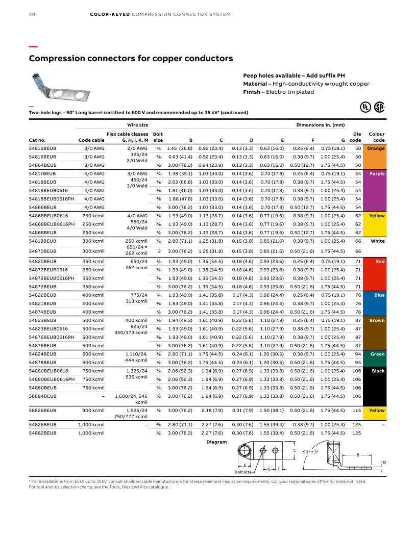
B1 copy starts here
B2 copy starts here
B3 copy starts here
40 CO LO R- K E Y E D CO M PR E SSI O N CO N N EC TO R S Y S TEM
—Compression connectors for copper conductors
Peep holes available – Add suffix PHMaterial – High-conductivity wrought copperFinish – Electro tin plated
Cat no.
Wire size
Bolt size
Dimensions in. (mm)
Die code
Colour codeCode cable
Flex cable classes G, H, I, K, M B C D E F G
54815BEUB 3/0 AWG 2/0 AWG325/24
2/0 Weld
1/4 1.45 (36.8) 0.92 (23.4) 0.13 (3.3) 0.63 (16.0) 0.25 (6.4) 0.75 (19.1) 50 Orange
54816BEUB 3/0 AWG 3/8 0.63 (41.4) 0.92 (23.4) 0.13 (3.3) 0.63 (16.0) 0.38 (9.7) 1.00 (25.4) 50
54864BEUB 3/0 AWG 1/2 3.00 (76.2) 0.94 (23.9) 0.13 (3.3) 0.63 (16.0) 0.50 (12.7) 1.75 (44.5) 50
54817BEUB 4/0 AWG 3/0 AWG450/24
3/0 Weld
1/4 1.38 (35.1) 1.03 (33.0) 0.14 (3.6) 0.70 (17.8) 0.25 (6.4) 0.75 (19.1) 54 Purple
54818BEUB 4/0 AWG 3/8 2.63 (66.8) 1.03 (33.0) 0.14 (3.6) 0.70 (17.8) 0.38 (9.7) 1.75 (44.5) 54
54818BEUB0616 4/0 AWG 3/8 1.81 (46.0) 1.03 (33.0) 0.14 (3.6) 0.70 (17.8) 0.38 (9.7) 1.00 (25.4) 54
54818BEUB0616PH 4/0 AWG 3/8 1.88 (47.8) 1.03 (33.0) 0.14 (3.6) 0.70 (17.8) 0.38 (9.7) 1.00 (25.4) 54
54866BEUB 4/0 AWG 1/2 3.00 (76.2) 1.03 (33.0) 0.14 (3.6) 0.70 (17.8) 0.50 (12.7) 1.75 (44.5) 54
54868BEUB0616 250 kcmil 4/0 AWG550/24
4/0 Weld
3/8 1.93 (49.0) 1.13 (28.7) 0.14 (3.6) 0.77 (19.6) 0.38 (9.7) 1.00 (25.4) 62 Yellow
54868BEUB0616PH 250 kcmil 3/8 1.93 (49.0) 1.13 (28.7) 0.14 (3.6) 0.77 (19.6) 0.38 (9.7) 1.00 (25.4) 62
54868BEUB 250 kcmil 1/2 3.00 (76.2) 1.13 (28.7) 0.14 (3.6) 0.77 (19.6) 0.50 (12.7) 1.75 (44.5) 62
54819BEUB 300 kcmil 250 kcmil650/24 = 262 kcmil
3/8 2.80 (71.1) 1.25 (31.8) 0.15 (3.8) 0.85 (21.6) 0.38 (9.7) 1.00 (25.4) 66 White
54870BEUB 300 kcmil 2 3.00 (76.2) 1.25 (31.8) 0.15 (3.8) 0.85 (21.6) 0.50 (21.6) 1.75 (44.5) 66
54820BEUB 350 kcmil 650/24262 kcmil
1/4 1.93 (49.0) 1.36 (34.5) 0.18 (4.6) 0.93 (23.6) 0.25 (6.4) 0.75 (19.1) 71 Red
54872BEUB0616 350 kcmil 3/8 1.93 (49.0) 1.36 (34.5) 0.18 (4.6) 0.93 (23.6) 0.38 (9.7) 1.00 (25.4) 71
54872BEUB0616PH 350 kcmil 3/8 1.93 (49.0) 1.36 (34.5) 0.18 (4.6) 0.93 (23.6) 0.38 (9.7) 1.00 (25.4) 71
54872BEUB 350 kcmil 1/2 3.00 (76.2) 1.36 (34.5) 0.18 (4.6) 0.93 (23.6) 0.50 (21.6) 1.75 (44.5) 71
54822BEUB 400 kcmil 775/24313 kcmil
1/4 1.93 (49.0) 1.41 (35.8) 0.17 (4.3) 0.96 (24.4) 0.25 (6.4) 0.75 (19.1) 76 Blue
54821BEUB 400 kcmil 3/8 1.93 (49.0) 1.41 (35.8) 0.17 (4.3) 0.96 (24.4) 0.38 (9.7) 1.00 (25.4) 76
54874BEUB 400 kcmil 1/2 3.00 (76.2) 1.41 (35.8) 0.17 (4.3) 0.96 (24.4) 0.50 (21.6) 1.75 (44.5) 76
54823BEUB 500 kcmil 400 kcmil925/24
350/373 kcmil
1/4 1.94 (49.3) 1.61 (40.9) 0.22 (5.6) 1.10 (27.9) 0.25 (6.4) 0.75 (19.1) 87 Brown
54823BEUB0616 500 kcmil 3/8 1.93 (49.0) 1.61 (40.9) 0.22 (5.6) 1.10 (27.9) 0.38 (9.7) 1.00 (25.4) 87
54876BEUB0616PH 500 kcmil 3/8 1.93 (49.0) 1.61 (40.9) 0.22 (5.6) 1.10 (27.9) 0.38 (9.7) 1.00 (25.4) 87
54876BEUB 500 kcmil 1/2 3.00 (76.2) 1.61 (40.9) 0.22 (5.6) 1.10 (27.9) 0.50 (21.6) 1.75 (44.5) 87
54824BEUB 600 kcmil 1,110/24, 444 kcmil
3/8 2.80 (71.1) 1.75 (44.5) 0.24 (6.1) 1.20 (30.5) 0.38 (9.7) 1.00 (25.4) 94 Green
54878BEUB 600 kcmil 1/2 3.00 (76.2) 1.75 (44.5) 0.24 (6.1) 1.20 (30.5) 0.50 (21.6) 1.75 (44.5) 94
54880BEUB0616 750 kcmil 1,325/24535 kcmil
3/8 2.06 (52.3) 1.94 (6.9) 0.27 (6.9) 1.33 (33.8) 0.50 (21.6) 1.00 (25.4) 106 Black
54880BEUB0616PH 750 kcmil 3/8 2.06 (52.3) 1.94 (6.9) 0.27 (6.9) 1.33 (33.8) 0.50 (21.6) 1.00 (25.4) 106
54880BEUB 750 kcmil 1/2 3.00 (76.2) 1.94 (6.9) 0.27 (6.9) 1.33 (33.8) 0.50 (21.6) 1.75 (44.5) 106
58884BEUB – 1,600/24, 646 kcmil
1/2 3.00 (76.2) 1.94 (6.9) 0.27 (6.9) 1.33 (33.8) 0.50 (21.6) 1.75 (44.5) 106
58826BEUB 900 kcmil 1,925/24750/777 kcmil
1/2 3.00 (76.2) 2.18 (7.9) 0.31 (7.9) 1.50 (38.1) 0.50 (21.6) 1.75 (44.5) 115 Yellow
54826BEUB 1,000 kcmil – 3/8 2.80 (71.1) 2.27 (7.6) 0.30 (7.6) 1.55 (39.4) 0.38 (9.7) 1.00 (25.4) 125 –
54882BEUB 1,000 kcmil 1/2 3.00 (76.2) 2.27 (7.6) 0.30 (7.6) 1.55 (39.4) 0.50 (21.6) 1.75 (44.5) 125
—Two-hole lugs – 90° Long barrel certified to 600 V and recommended up to 35 kV¥ (continued)
¥ For installations from 16 kV up to 35 kV, consult shielded cable manufacturers for stress relief and insulation requirements. Call your regional sales office for sizes not listed.For tool and die selection charts, see the Tools, Dies and Kits catalogue.
Diagram
Bolt Size
90° ± 3 °B
D
G F
C
EF
Bolt sizeG
E
CB
D
90° ± 3°

41
—Compression connectors for copper conductorsNarrow-tongue lugs – Ideal for confined-space terminations
To meet increasing demand for smaller components in today’s panels and switchgear, ABB has expanded its line of Color-Keyed narrow-tongue lugs to include two-hole and angled lugs. These improved lugs have been precision engineered for consistency in width the entire length of the connector, from barrel to tongue, ensuring a reliable fit in confined-space applications.• Narrow-width tongue and barrel, engineered
for dimensional consistency the entire length of the lug
• Perfect for connections in limited-space applications
• High-conductivity copper construction• Electrolytically tin-plated finish resists corrosion• ABB Color-Keyed marking system makes
connections and verification easy • Double-chamfered barrel eases insertion of wire
Technical specifications• Certified rating: 600 V• Recommended rating: Up to 35 kV¥
• Material: 99% pure high-conductivity seamless wrought copper
• Finish: Electro tin plated• Standards: UL listed, CSA certified
and RoHS compliant
Ideal for use in:• Panels• Switchgear• Molded-case circuit breakers• Motor starters• Other limited-space OEM applications
Now available in:• One-hole• Two-hole• Straight• 45° angled• 90° angled
¥ For installations from 16 kV up to 35 kV, consult shielded cable manufacturers for stress relief and insulation requirements.
CO M PR E SSI O N CO N N EC TO R S FO R CO PPER CO N D U C TO R S
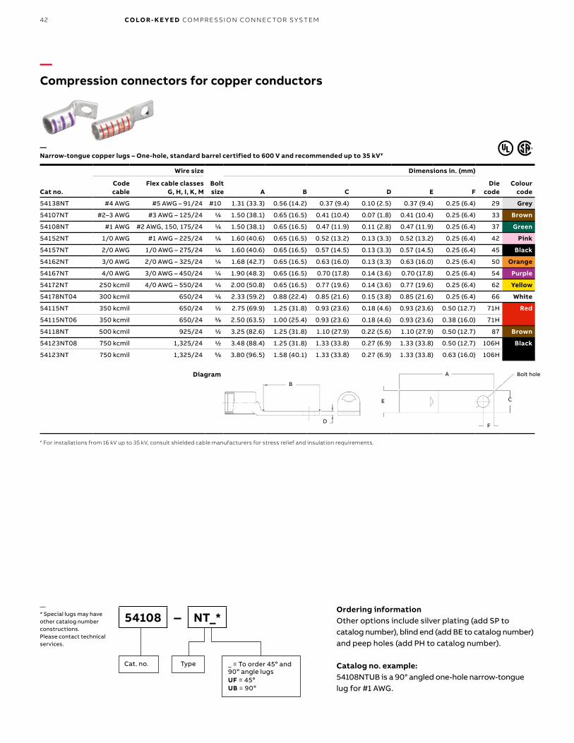
B1 copy starts here
B2 copy starts here
B3 copy starts here
42 CO LO R- K E Y E D CO M PR E SSI O N CO N N EC TO R S Y S TEM
Ordering informationOther options include silver plating (add SP to catalog number), blind end (add BE to catalog number) and peep holes (add PH to catalog number).
Catalog no. example: 54108NTUB is a 90° angled one-hole narrow-tongue lug for #1 AWG.
54108 – NT_*
TypeCat. no. _ = To order 45o and 90o angle lugs UF = 45oUB = 90o
—* Special lugs may have other catalog number constructions. Please contact technical services.
—Compression connectors for copper conductors
Cat no.
Wire size
Bolt size
Dimensions in. (mm)
Die code
Colour code
Code cable
Flex cable classes G, H, I, K, M A B C D E F
54138NT #4 AWG #5 AWG – 91/24 #10 1.31 (33.3) 0.56 (14.2) 0.37 (9.4) 0.10 (2.5) 0.37 (9.4) 0.25 (6.4) 29 Grey
54107NT #2–3 AWG #3 AWG – 125/24 1/4 1.50 (38.1) 0.65 (16.5) 0.41 (10.4) 0.07 (1.8) 0.41 (10.4) 0.25 (6.4) 33 Brown
54108NT #1 AWG #2 AWG, 150, 175/24 1/4 1.50 (38.1) 0.65 (16.5) 0.47 (11.9) 0.11 (2.8) 0.47 (11.9) 0.25 (6.4) 37 Green
54152NT 1/0 AWG #1 AWG – 225/24 1/4 1.60 (40.6) 0.65 (16.5) 0.52 (13.2) 0.13 (3.3) 0.52 (13.2) 0.25 (6.4) 42 Pink
54157NT 2/0 AWG 1/0 AWG – 275/24 1/4 1.60 (40.6) 0.65 (16.5) 0.57 (14.5) 0.13 (3.3) 0.57 (14.5) 0.25 (6.4) 45 Black
54162NT 3/0 AWG 2/0 AWG – 325/24 1/4 1.68 (42.7) 0.65 (16.5) 0.63 (16.0) 0.13 (3.3) 0.63 (16.0) 0.25 (6.4) 50 Orange
54167NT 4/0 AWG 3/0 AWG – 450/24 1/4 1.90 (48.3) 0.65 (16.5) 0.70 (17.8) 0.14 (3.6) 0.70 (17.8) 0.25 (6.4) 54 Purple
54172NT 250 kcmil 4/0 AWG – 550/24 1/4 2.00 (50.8) 0.65 (16.5) 0.77 (19.6) 0.14 (3.6) 0.77 (19.6) 0.25 (6.4) 62 Yellow
54178NT04 300 kcmil 650/24 1/4 2.33 (59.2) 0.88 (22.4) 0.85 (21.6) 0.15 (3.8) 0.85 (21.6) 0.25 (6.4) 66 White
54115NT 350 kcmil 650/24 1/2 2.75 (69.9) 1.25 (31.8) 0.93 (23.6) 0.18 (4.6) 0.93 (23.6) 0.50 (12.7) 71H Red
54115NT06 350 kcmil 650/24 3/8 2.50 (63.5) 1.00 (25.4) 0.93 (23.6) 0.18 (4.6) 0.93 (23.6) 0.38 (16.0) 71H
54118NT 500 kcmil 925/24 1/2 3.25 (82.6) 1.25 (31.8) 1.10 (27.9) 0.22 (5.6) 1.10 (27.9) 0.50 (12.7) 87 Brown
54123NT08 750 kcmil 1,325/24 1/2 3.48 (88.4) 1.25 (31.8) 1.33 (33.8) 0.27 (6.9) 1.33 (33.8) 0.50 (12.7) 106H Black
54123NT 750 kcmil 1,325/24 5/8 3.80 (96.5) 1.58 (40.1) 1.33 (33.8) 0.27 (6.9) 1.33 (33.8) 0.63 (16.0) 106H
—Narrow-tongue copper lugs – One-hole, standard barrel certified to 600 V and recommended up to 35 kV¥
¥ For installations from 16 kV up to 35 kV, consult shielded cable manufacturers for stress relief and insulation requirements.
H
E
A
F
C
Bolt Hole
B
D
Diagram
E
A
F
C
Bolt hole
B
D

43
Ordering informationOther options include silver plating (add SP to catalog number), blind end (add BE to catalog number) and peep holes (add PH to catalog number).
Catalog no. example: 54212NTUB is a 90° angled one-hole narrow-tongue lug for #1 AWG.
54212 – NT_*
TypeCat. no. _ = To order 45o and 90o angle lugs UF = 45oUB = 90o
—* Special lugs may have other catalog number constructions. Please contact technical services.
Cat no.
Wire size
Bolt size
Dimensions in. (mm)
Die code
Colour code
Code cable
Flex cable classes G, H, I, K, M A B C D E F H
54206NT0310 #4 AWG # 5 AWG – 91/24 #10 1.88 (47.8) 1.13 (28.7) 0.37 (9.4) 0.10 (2.5) 0.37 (9.4) 0.25 (6.4) 0.63 (16.0) 29 Grey
54207NT #2–3 AWG #3 AWG – 125/24 1/4 2.04 (61.0) 1.19 (30.2) 0.41 (10.4) 0.11 (2.8) 0.41 (10.4) 0.25 (6.4) 0.63 (16.0) 33 Brown
54207NT0412 #2–3 AWG #3 AWG – 125/24 1/4 2.16 (54.9) 1.31 (33.3) 0.41 (10.4) 0.11 (2.8) 0.41 (10.4) 0.25 (6.4) 0.75 (19.1) 33
54207NT0416 #2–3 AWG #3 AWG – 125/24 1/4 2.41 (61.2) 1.56 (39.6) 0.41 (10.4) 0.11 (2.8) 0.41 (10.4) 0.25 (6.4) 1.00 (25.4) 33
54208NT #1 AWG #2 AWG – 150, 175/24 1/4 2.40 (61.0) 1.19 (30.2) 0.47 (11.9) 0.11 (2.8) 0.47 (11.9) 0.25 (6.4) 0.63 (16.0) 37 Green
54208NT0516 #1 AWG #2 AWG – 150, 175/24 5⁄16 2.63 (66.8) 1.78 (45.2) 0.47 (11.9) 0.11 (2.8) 0.47 (11.9) 0.38 (9.7) 1.00 (25.4) 37
54255NT 1/0 AWG #1 AWG – 225/24 5⁄16 2.61 (66.3) 1.66 (42.2) 0.52 (13.2) 0.14 (3.6) 0.52 (13.2) 0.38 (9.7) 0.88 (22.4) 42 Pink
54261NT 2/0 AWG 1/0 AWG – 275/24 5⁄16 2.66 (67.6) 1.66 (42.2) 0.57 (14.5) 0.14 (3.6) 0.52 (13.2) 0.38 (9.7) 0.88 (22.4) 45 Black
54210NT 2/0 AWG 1/0 AWG – 275/24 3/8 2.82 (71.6) 1.82 (46.2) 0.57 (14.5) 0.14 (3.6) 0.52 (13.2) 0.38 (9.7) 1.00 (25.4) 45
54266NT 3/0 AWG 2/0 AWG – 325/24 5⁄16 2.88 (73.2) 1.78 (45.2) 0.63 (16.0) 0.13 (3.3) 0.63 (16.0) 0.38 (9.7) 1.00 (25.4) 50 Orange
54211NT 3/0 AWG 2/0 AWG – 325/24 3/8 2.92 (74.2) 1.82 (46.2) 0.63 (16.0) 0.13 (3.3) 0.63 (16.0) 0.38 (9.7) 1.00 (25.4) 50
54212NT 4/0 AWG 3/0 AWG – 450/24 3/8 3.07 (94.0) 1.82 (46.2) 0.70 (17.8) 0.14 (3.6) 0.70 (17.8) 0.38 (9.7) 1.00 (25.4) 54 Purple
54213NT 250 kcmil 4/0 AWG – 550/24 3/8 3.17 (80.5) 1.82 (46.2) 0.77 (19.6) 0.14 (3.6) 0.77 (19.6) 0.38 (9.7) 1.00 (25.4) 62 Yellow
54275NT 250 kcmil 4/0 AWG – 550/24 1/2 4.16 (105.7) 2.81 (71.4) 0.77 (19.6) 0.14 (3.6) 0.77 (19.6) 0.50 (12.7) 1.75 (44.5) 62
54282NT 350 kcmil 650/24 1/2 4.36 (110.7) 2.81 (71.4) 0.93 (23.6) 0.18 (4.6) 0.93 (23.6) 0.50 (12.7) 1.75 (44.5) 71H Red
54218NT 500 kcmil 925/24 3/8 4.57 (116.1) 2.57 (65.3) 1.10 (27.9) 0.22 (5.6) 1.10 (27.9) 0.38 (9.7) 1.75 (44.5) 87 Brown
54286NT 500 kcmil 925/24 1/2 4.81 (122.2) 2.81 (71.4) 1.10 (27.9) 0.22 (5.6) 1.10 (27.9) 0.50 (12.7) 1.75 (44.5) 87
54878BENTPH 600 kcmil 1,100/24 1/2 5.83 (148.1) 3.00 (76.2) 1.20 (30.5) 0.24 (6.1) 1.20 (30.5) 0.50 (12.7) 1.75 (44.5) 94 Green
54223NT0628 750 kcmil 1,325/24 3/8 4.79 (121.7) 2.57 (65.3) 1.33 (33.8) 0.27 (6.9) 1.33 (33.8) 0.38 (9.7) 1.75 (44.5) 106H Black
54223NT 750 kcmil 1,325/24 1/2 5.04 (137.2) 2.81 (71.4) 1.33 (33.8) 0.27 (6.9) 1.33 (33.8) 0.50 (12.7) 1.75 (44.5) 106H
58884BENTPH – 1,600/24 1/2 6.16 (156.5) 3.00 (76.2) 1.33 (33.8) 0.24 (6.1) 1.20 (30.5) 0.50 (12.7) 1.75 (44.5) 106H
Catalogue numbers 54878BENTPH and 58884BENTPH include peep holes.¥ For installations from 16 kV up to 35 kV, consult shielded cable manufacturers for stress relief and insulation requirements.
—Compression connectors for copper conductors
—Narrow-tongue copper lugs – Two-hole, standard barrel certified to 600 V and recommended up to 35 kV¥
Diagram
E
A
F
C
Bolt hole
B
D H
CO M PR E SSI O N CO N N EC TO R S FO R CO PPER CO N D U C TO R S
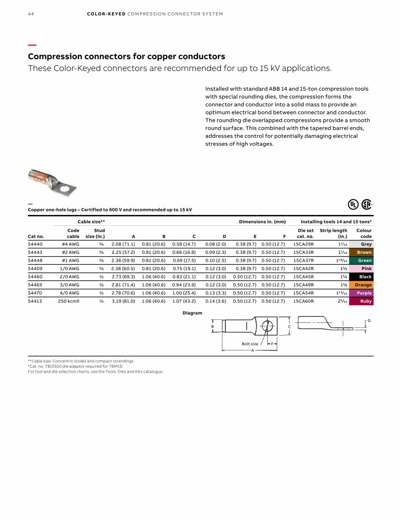
B1 copy starts here
B2 copy starts here
B3 copy starts here
44 CO LO R- K E Y E D CO M PR E SSI O N CO N N EC TO R S Y S TEM
—Compression connectors for copper conductorsThese Color-Keyed connectors are recommended for up to 15 kV applications.
Cat no.
Cable size** Dimensions in. (mm) Installing tools 14 and 15 tons*
Code cable
Stud size (in.) A B C D E F
Die set cat. no.
Strip length (in.)
Colour code
54440 #4 AWG 3/8 2.08 (71.1) 0.81 (20.6) 0.58 (14.7) 0.08 (2.0) 0.38 (9.7) 0.50 (12.7) 15CA29R 17⁄16 Grey
54443 #2 AWG 3/8 2.25 (57.2) 0.81 (20.6) 0.66 (16.8) 0.09 (2.3) 0.38 (9.7) 0.50 (12.7) 15CA33R 17⁄16 Brown
54448 #1 AWG 3/8 2.36 (59.9) 0.81 (20.6) 0.69 (17.5) 0.10 (2.5) 0.38 (9.7) 0.50 (12.7) 15CA37R 118⁄32 Green
54409 1/0 AWG 3/8 2.38 (60.5) 0.81 (20.6) 0.75 (19.1) 0.12 (3.0) 0.38 (9.7) 0.50 (12.7) 15CA42R 15/8 Pink
54460 2/0 AWG 1/2 2.73 (69.3) 1.06 (40.6) 0.83 (21.1) 0.12 (3.0) 0.50 (12.7) 0.50 (12.7) 15CA45R 15/8 Black
54465 3/0 AWG 1/2 2.81 (71.4) 1.06 (40.6) 0.94 (23.9) 0.12 (3.0) 0.50 (12.7) 0.50 (12.7) 15CA49R 13/4 Orange
54470 4/0 AWG 1/2 2.78 (70.6) 1.06 (40.6) 1.00 (25.4) 0.13 (3.3) 0.50 (12.7) 0.50 (12.7) 15CA54R 113⁄16 Purple
54413 250 kcmil 1/2 3.19 (81.0) 1.06 (40.6) 1.07 (43.2) 0.14 (3.6) 0.50 (12.7) 0.50 (12.7) 15CA60R 21/32 Ruby
—Copper one-hole lugs – Certified to 600 V and recommended up to 15 kV
Installed with standard ABB 14 and 15-ton compression tools with special rounding dies, the compression forms the connector and conductor into a solid mass to provide an optimum electrical bond between connector and conductor. The rounding die overlapped compressions provide a smooth round surface. This combined with the tapered barrel ends, addresses the control for potentially damaging electrical stresses of high voltages.
**Cable size: Concentric (code) and compact strandings*Cat. no. TB15500 die adaptor required for TBM15IFor tool and die selection charts, see the Tools, Dies and Kits catalogue.
Diagram
D
Bolt Size
B
F
C
A
D
C
FBolt size
B
A
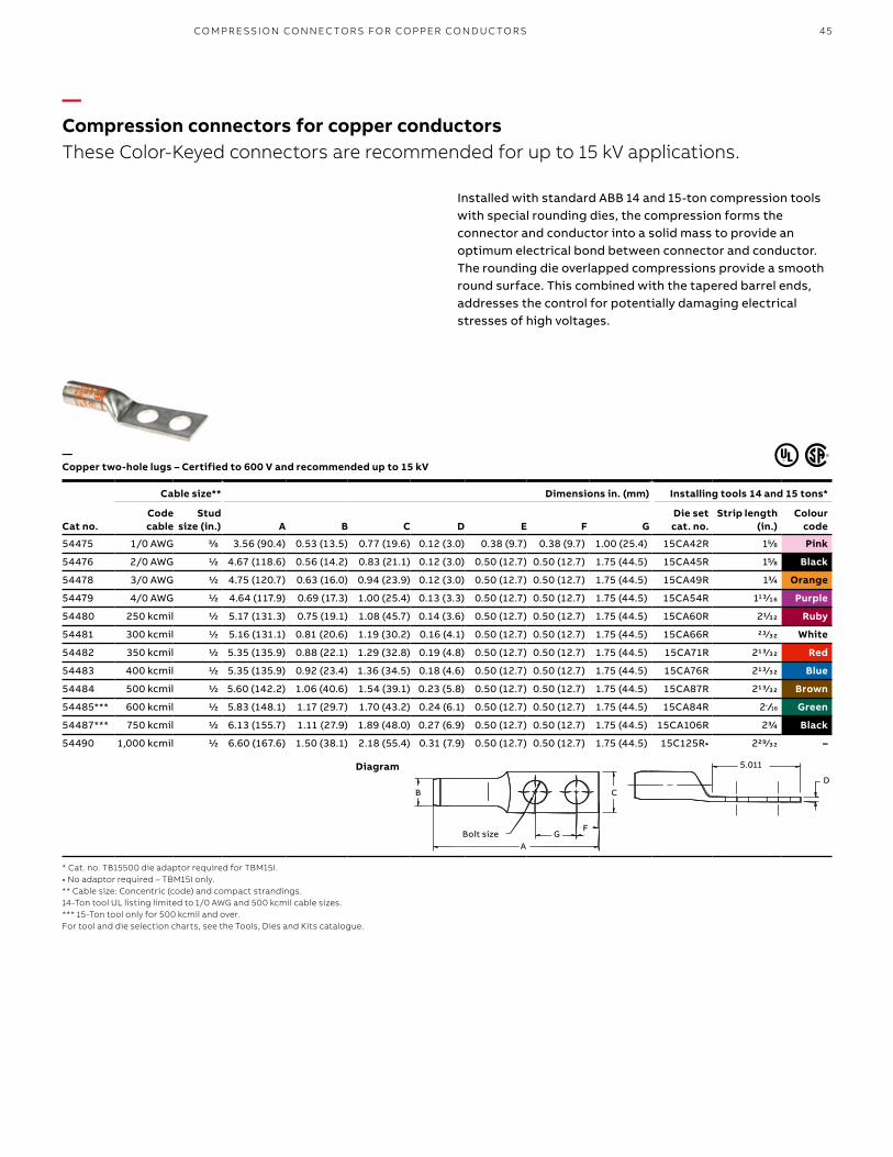
45
—Compression connectors for copper conductorsThese Color-Keyed connectors are recommended for up to 15 kV applications.
Cat no.
Cable size** Dimensions in. (mm) Installing tools 14 and 15 tons*
Code cable
Stud size (in.) A B C D E F G
Die set cat. no.
Strip length (in.)
Colour code
54475 1/0 AWG 3/8 3.56 (90.4) 0.53 (13.5) 0.77 (19.6) 0.12 (3.0) 0.38 (9.7) 0.38 (9.7) 1.00 (25.4) 15CA42R 15/8 Pink
54476 2/0 AWG 1/2 4.67 (118.6) 0.56 (14.2) 0.83 (21.1) 0.12 (3.0) 0.50 (12.7) 0.50 (12.7) 1.75 (44.5) 15CA45R 15/8 Black
54478 3/0 AWG 1/2 4.75 (120.7) 0.63 (16.0) 0.94 (23.9) 0.12 (3.0) 0.50 (12.7) 0.50 (12.7) 1.75 (44.5) 15CA49R 13/4 Orange
54479 4/0 AWG 1/2 4.64 (117.9) 0.69 (17.3) 1.00 (25.4) 0.13 (3.3) 0.50 (12.7) 0.50 (12.7) 1.75 (44.5) 15CA54R 113⁄16 Purple
54480 250 kcmil 1/2 5.17 (131.3) 0.75 (19.1) 1.08 (45.7) 0.14 (3.6) 0.50 (12.7) 0.50 (12.7) 1.75 (44.5) 15CA60R 21/32 Ruby
54481 300 kcmil 1/2 5.16 (131.1) 0.81 (20.6) 1.19 (30.2) 0.16 (4.1) 0.50 (12.7) 0.50 (12.7) 1.75 (44.5) 15CA66R 23⁄32 White
54482 350 kcmil 1/2 5.35 (135.9) 0.88 (22.1) 1.29 (32.8) 0.19 (4.8) 0.50 (12.7) 0.50 (12.7) 1.75 (44.5) 15CA71R 213⁄32 Red
54483 400 kcmil 1/2 5.35 (135.9) 0.92 (23.4) 1.36 (34.5) 0.18 (4.6) 0.50 (12.7) 0.50 (12.7) 1.75 (44.5) 15CA76R 213⁄32 Blue
54484 500 kcmil 1/2 5.60 (142.2) 1.06 (40.6) 1.54 (39.1) 0.23 (5.8) 0.50 (12.7) 0.50 (12.7) 1.75 (44.5) 15CA87R 213⁄32 Brown
54485*** 600 kcmil 1/2 5.83 (148.1) 1.17 (29.7) 1.70 (43.2) 0.24 (6.1) 0.50 (12.7) 0.50 (12.7) 1.75 (44.5) 15CA84R 2- ⁄16 Green
54487*** 750 kcmil 1/2 6.13 (155.7) 1.11 (27.9) 1.89 (48.0) 0.27 (6.9) 0.50 (12.7) 0.50 (12.7) 1.75 (44.5) 15CA106R 23/4 Black
54490 1,000 kcmil 1/2 6.60 (167.6) 1.50 (38.1) 2.18 (55.4) 0.31 (7.9) 0.50 (12.7) 0.50 (12.7) 1.75 (44.5) 15C125R• 229⁄32 –
—Copper two-hole lugs – Certified to 600 V and recommended up to 15 kV
Installed with standard ABB 14 and 15-ton compression tools with special rounding dies, the compression forms the connector and conductor into a solid mass to provide an optimum electrical bond between connector and conductor. The rounding die overlapped compressions provide a smooth round surface. This combined with the tapered barrel ends, addresses the control for potentially damaging electrical stresses of high voltages.
* Cat. no. TB15500 die adaptor required for TBM15I.• No adaptor required – TBM15I only.** Cable size: Concentric (code) and compact strandings.14-Ton tool UL listing limited to 1/0 AWG and 500 kcmil cable sizes.*** 15-Ton tool only for 500 kcmil and over.For tool and die selection charts, see the Tools, Dies and Kits catalogue.
Diagram 5.011
D
GFBolt Size
A
CB
Bolt size
5.011
DC
F
B
AG
CO M PR E SSI O N CO N N EC TO R S FO R CO PPER CO N D U C TO R S

B1 copy starts here
B2 copy starts here
B3 copy starts here
46 CO LO R- K E Y E D CO M PR E SSI O N CO N N EC TO R S Y S TEM
Cat. no.
Wire size (AWG or kcmil)* Classes Bolt size (in.)
Dimensions in. (mm)
Die code
Colour code
Code cable Navy Flex G H I K M A B C D F
54104BS 8 23 37/24 8 8 – 8 8 #10 1.06 (40.6) 0.46 (11.7) 0.40 (10.2) 0.07 (1.8) 0.21 (5.3) 21 Red
54105BS 6 30 61/24 5 5 5 5 5 1/4 1.18 (30.0) 0.56 (14.2) 0.43 (10.9) 0.10 (2.5) 0.25 (6.4) 24 Blue
54106BS 4 40–50 91/24 5 5 5 5 5 1/4 1.28 (32.5) 0.56 (14.2) 0.56 (14.2) 0.10 (2.5) 0.25 (6.4) 29 Grey
54139BS 3–4 40–50 91/24 4 4 4 4 4 5/16 1.43 (36.3) 0.78 (19.8) 0.59 (19.8) 0.07 (1.8) 0.34 (8.6) 29
54142BS 2 60 125/24 3 3 3 3 3 5/16 1.53 (38.9) 0.71 (18.0) 0.65 (16.5) 0.07 (1.8) 0.34 (8.6) 33 Brown
54147BS 1 75 150, 175/24 2 2 2 2 2 5/16 1.91 (48.5) 0.71 (18.0) 0.67 (17.0) 0.12 (3.0) 0.38 (9.7) 37 Green
54153BS 1/0 100 225/24 1 1 1 1 1 5/16 1.63 (41.4) 0.71 (18.0) 0.75 (19.1) 0.14 (3.6) 0.38 (9.7) 42 Pink
54110BS 2/0 125 275/24 1/0 1/0 1/0 1/0 1/0 3/8 1.88 (47.8) 0.81 (20.6) 0.81 (20.6) 0.14 (3.6) 0.38 (9.7) 45 Black
54165BS 3/0 150 325/24 2/0 2/0 2/0 2/0 2/0 1/2 2.21 (56.1) 1.06 (40.6) 0.93 (23.6) 0.14 (3.6) 0.50 (12.7) 50 Orange
54170BS 4/0 200 450/24 3/0 3/0 3/0 3/0 3/0 1/2 2.31 (58.7) 1.06 (40.6) 1.03 (33.0) 0.15 (3.8) 0.50 (12.7) 54 Purple
58165BS 250 – 550/24 4/0 4/0 4/0 4/0 4/0 1/2 2.46 (62.5) 1.12 (28.4) 1.25 (31.8) 0.18 (4.6) 0.50 (12.7) 62 Yellow
54114BS 300 300 650/24 250 250 250 250 – 1/2 2.46 (62.5) 1.12 (28.4) 1.25 (31.8) 0.18 (4.6) 0.50 (12.7) 66 White
5411440BS 300 300 650/24 250 250 250 250 – 1/2 2.38 (60.5) 1.12 (28.4) 1.25 (31.8) 0.18 (4.6) 0.50 (12.7) 66
54115260BS 350 350 650/24 – – 250 250 250 1/2 2.63 (66.8) 1.18 (30.0) 1.38 (35.1) 0.20 (5.1) 0.56 (14.2) 66
54185BS 400 400 775/24 300 300 300 300 300 5/8 3.43 (87.1) 1.68 (42.7) 1.40 (35.6) 0.21 (5.3) 0.81 (20.6) 76 Blue
58177BS 500 – 925/24 400 400 400 400 400 5/8 3.00 (76.2) 1.31 (33.3) 1.63 (41.4) 0.25 (6.4) 0.81 (20.6) 80 –
58180BS 600 – 1,100/24 – – 450 450 450 5/8 3.63 (92.2) 1.68 (42.7) 1.78 (45.2) 0.26 (6.6) 0.81 (20.6) 94 Green
54122BS 700 – 1,325/24 500 500 500 500 500 5/8 3.63 (92.2) 1.68 (42.7) 1.78 (45.2) 0.28 (7.1) 0.81 (20.6) 99 Pink
54123BS 750 – – 600 – – – 550 5/8 3.63 (92.2) 1.68 (42.7) 1.93 (49.0) 0.31 (7.9) 0.81 (20.6) 106 Black
54124BS 800 800 – – – – 600 – 5/8 3.81 (96.8) 1.68 (42.7) 2.00 (50.8) 0.31 (7.9) 0.63 (16.0) 107 Orange
54126BS 900 – 1,925/24 – – 750 – – 5/8 4.12 (104.6) 1.81 (46.0) 2.18 (55.4) 0.37 (9.4) 0.88 (22.4) 115 Yellow
—Compression connectors for copper conductors
—Bell-ended lugs – Standard barrel certified to 600 V and recommended up to 35 kV¥
¥ For installations from 16 kV up to 35 kV, consult shielded cable manufacturers for stress relief and insulation requirements.* Stranding will differ per class.For tool and die selection charts, see the Tools, Dies and Kits catalogue.
Bolt Size
B
D
AF
C
Diagram
C
FBolt sizeA
B
D

47
Cat. no.
Wire size (AWG or kcmil)* Classes Bolt size (in.)
Dimensions in. (mm)
Die code
Colour code
Code cable Navy Flex G H I K M A B C D E F G
54850BEBS 8 23 8 8 8 – 8 – 1/4 2.19 (55.6)
1.88 (47.8)
0.42 (10.7)
0.07 (1.8)
0.26 (6.6)
0.25 (6.4)
0.63 (16.0)
21 Red
54851BEBS 8 23 8 8 8 – 8 – 1/4 2.31 (58.7)
1.59 (32.8)
0.47 (11.9)
0.06 (1.5)
0.26 (6.6)
0.25 (6.4)
0.75 (19.1)
21
54851BE0616BS 8 23 8 8 8 – 8 – 3/8 3.00 (76.2)
2.10 (53.3)
0.56 (14.2)
0.06 (1.5)
0.26 (6.6)
0.38 (9.7)
1.00 (25.4)
21
54852BE0616BS 6 30 6 5 5 5 5 – 3/8 2.93 (74.4)
1.93 (49.0)
0.59 (15.0)
0.06 (1.5)
0.30 (7.6)
0.38 (9.7)
1.00 (25.4)
24 Blue
54852BEBS 6 30 6 5 5 5 5 – 1/4 2.28 (57.9)
1.28 (32.5)
0.44 (11.2)
0.08 (2.0)
0.30 (7.6)
0.25 (6.4)
0.63 (16.0)
24
54852BE0412BS 6 30 6 5 5 5 5 – 1/4 2.43 (61.7)
1.43 (36.3)
0.43 (10.9)
0.07 (1.8)
0.30 (7.6)
0.25 (6.4)
0.75 (19.1)
24
54854BEBS 4–3 40–50 5 5 5 5 5 – 1/4 2.31 (58.7)
1.19 (30.2)
0.52 (13.2)
0.10 (2.5)
0.37 (9.4)
0.25 (6.4)
0.63 (16.0)
29 Grey
54854BE0412BS 4–3 40–50 5 5 5 5 5 – 1/4 2.31 (58.7)
1.31 (33.3)
0.56 (14.2)
0.09 (2.3)
0.37 (9.4)
0.25 (6.4)
0.75 (19.1)
29
54854BE0616BS 4–3 40–50 5 5 5 5 5 – 3/8 3.13 (79.5)
1.98 (50.3)
0.59 (15.0)
0.09 (2.3)
0.37 (9.4)
0.38 (9.7)
1.00 (25.4)
29
54855BE0412BS 2 60 3 3 3 3 3 3 1/4 2.63 (66.8)
1.35 (34.3)
0.68 (17.3)
0.11 (2.8)
0.41 (10.4)
0.25 (6.4)
0.75 (19.1)
33 Brown
54855BEBS 2 60 3 3 3 3 3 3 1/4 2.43 (61.7)
1.28 (32.5)
0.59 (15.0)
0.11 (2.8)
0.41 (10.4)
0.25 (6.4)
0.63 (16.0)
33
54856BEBS 2 60 3 3 3 3 3 3 3⁄16 2.78 (70.6)
1.63 (41.4)
0.59 (15.0)
0.11 (2.8)
0.41 (10.4)
0.38 (9.7)
0.75 (19.1)
33
54810BE0616BS 2 60 3 3 3 3 3 3 3/8 3.08 (96.5)
1.94 (49.3)
0.59 (15.0)
0.11 (2.8)
0.41 (10.4)
0.38 (9.7)
1.00 (25.4)
33
54811BEBS 2 60 3 3 3 3 3 3 1/2 4.28 (108.7)
3.00 (76.2)
0.88 (22.4)
0.09 (2.3)
0.41 (10.4)
0.50 (12.7)
1.75 (44.5)
33
54809BEBS 1 75 2 2 2 2 2 2 1/4 2.88 (73.2)
1.19 (30.2)
0.67 (17.0)
0.11 (2.8)
0.47 (11.9)
0.25 (6.4)
0.63 (16.0)
37 Green
54812BEBS 1 75 2 2 2 2 2 2 1/4 2.75 (69.9)
1.40 (35.6)
0.67 (17.0)
0.11 (2.8)
0.47 (11.9)
0.25 (6.4)
0.75 (19.1)
37
54858BEBS 1 75 2 2 2 2 2 2 5⁄16 2.97 (75.4)
1.63 (41.4)
0.67 (17.0)
0.11 (2.8)
0.47 (11.9)
0.38 (9.7)
0.88 (22.4)
37
54857BEBS 1 75 2 2 2 2 2 2 1/2 4.43 (112.5)
3.00 (76.2)
0.88 (22.4)
0.10 (2.5)
0.47 (11.9)
0.50 (12.7)
1.75 (44.5)
37
—Compression connectors for copper conductors
—Bell-ended lugs – Standard barrel certified to 600 V and recommended up to 35 kV¥
¥ For installations from 16 kV up to 35 kV, consult shielded cable manufacturers for stress relief and insulation requirements.* Stranding will differ per class.For tool and die selection charts, see the Tools, Dies and Kits catalogue.
Diagram B
D
Bolt Size G F
CE
A
B
D
Bolt Size G F
CE
A
B
DE
AG F
C
Bolt size
CO M PR E SSI O N CO N N EC TO R S FO R CO PPER CO N D U C TO R S
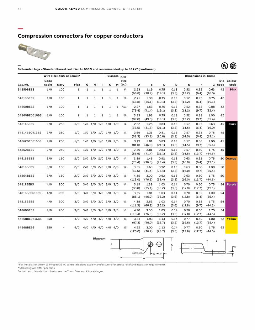
B1 copy starts here
B2 copy starts here
B3 copy starts here
48 CO LO R- K E Y E D CO M PR E SSI O N CO N N EC TO R S Y S TEM
Cat. no.
Wire size (AWG or kcmil)* Classes Bolt size (in.)
Dimensions in. (mm)
Die code
Colour code
Code cable Navy Flex G H I K M A B C D E F G
54859BEBS 1/0 100 1 1 1 1 1 1 1/4 2.63 (66.8)
1.19 (30.2)
0.75 (19.1)
0.13 (3.3)
0.52 (13.2)
0.25 (6.4)
0.63 (16.0)
42 Pink
54813BEBS 1/0 100 1 1 1 1 1 1 1/4 2.71 (68.8)
1.38 (35.1)
0.75 (19.1)
0.13 (3.3)
0.52 (13.2)
0.25 (6.4)
0.75 (19.1)
42
54860BEBS 1/0 100 1 1 1 1 1 1 5⁄16 2.97 (75.4)
1.63 (41.4)
0.75 (19.1)
0.13 (3.3)
0.52 (13.2)
0.38 (9.7)
0.88 (22.4)
42
54860BE0616BS 1/0 100 1 1 1 1 1 1 3/8 3.23 (82.0)
1.93 (49.0)
0.75 (19.1)
0.13 (3.3)
0.52 (13.2)
0.38 (9.7)
1.00 (25.4)
42
54814BEBS 2/0 250 1/0 1/0 1/0 1/0 1/0 1/0 1/4 2.62 (66.5)
1.25 (31.8)
0.83 (21.1)
0.13 (3.3)
0.57 (14.5)
0.25 (6.4)
0.63 (16.0)
45 Black
54814BE0412BS 2/0 250 1/0 1/0 1/0 1/0 1/0 1/0 1/4 2.69 (68.3)
1.31 (33.3)
0.81 (20.6)
0.13 (3.3)
0.57 (14.5)
0.25 (6.4)
0.75 (19.1)
45
54862BE0616BS 2/0 250 1/0 1/0 1/0 1/0 1/0 1/0 3/8 3.19 (81.0)
1.81 (46.0)
0.83 (21.1)
0.13 (3.3)
0.57 (14.5)
0.38 (9.7)
1.00 (25.4)
45
54862BEBS 2/0 250 1/0 1/0 1/0 1/0 1/0 1/0 1/2 2.20 (55.9)
2.81 (71.4)
0.83 (21.1)
0.13 (3.3)
0.57 (14.5)
0.50 (12.7)
1.75 (44.5)
45
54815BEBS 3/0 150 2/0 2/0 2/0 2/0 2/0 2/0 1/4 2.89 (73.4)
1.45 (36.8)
0.92 (23.4)
0.13 (3.3)
0.63 (16.0)
0.25 (6.4)
0.75 (19.1)
50 Orange
54816BEBS 3/0 150 2/0 2/0 2/0 2/0 2/0 2/0 3/8 3.25 (82.6)
1.63 (41.4)
0.92 (23.4)
0.13 (3.3)
0.63 (16.0)
0.38 (9.7)
1.00 (25.4)
50
54864BEBS 3/0 150 2/0 2/0 2/0 2/0 2/0 2/0 1/2 4.45 (113.0)
3.00 (76.2)
0.92 (23.4)
0.13 (3.3)
0.63 (16.0)
0.50 (12.7)
1.75 (44.5)
50
54817BEBS 4/0 200 3/0 3/0 3/0 3/0 3/0 3/0 1/4 3.15 (80.0)
1.38 (35.1)
1.03 (26.2)
0.14 (3.6)
0.70 (17.8)
0.50 (12.7)
0.75 (19.1)
54 Purple
54818BE0616BS 4/0 200 3/0 3/0 3/0 3/0 3/0 3/0 3/8 3.35 (85.1)
1.81 (46.0)
1.03 (26.2)
0.14 (3.6)
0.70 (17.8)
0.25 (6.4)
1.00 (25.4)
54
54818BEBS 4/0 200 3/0 3/0 3/0 3/0 3/0 3/0 3/8 4.38 (111.3)
2.63 (66.8)
1.03 (26.2)
0.14 (3.6)
0.70 (17.8)
0.38 (9.7)
1.75 (44.5)
54
54866BEBS 4/0 200 3/0 3/0 3/0 3/0 3/0 3/0 1/2 4.70 (119.4)
3.00 (76.2)
1.03 (26.2)
0.14 (3.6)
0.70 (17.8)
0.50 (12.7)
1.75 (44.5)
54
54868BE0616BS 250 – 4/0 4/0 4/0 4/0 4/0 4/0 3/8 3.83 (97.3)
1.93 (49.0)
1.13 (28.7)
0.14 (3.6)
0.77 (19.6)
0.50 (12.7)
1.00 (25.4)
62 Yellow
54868BEBS 250 – 4/0 4/0 4/0 4/0 4/0 4/0 1/2 4.92 (125.0)
3.00 (76.2)
1.13 (28.7)
0.14 (3.6)
0.77 (19.6)
0.50 (12.7)
1.75 (44.5)
62
—Compression connectors for copper conductors
—Bell-ended lugs – Standard barrel certified to 600 V and recommended up to 35 kV¥ (continued)
¥ For installations from 16 kV up to 35 kV, consult shielded cable manufacturers for stress relief and insulation requirements.* Stranding will differ per class.For tool and die selection charts, see the Tools, Dies and Kits catalogue.
Diagram
B
D
Bolt Size G F
CE
A
B
D
Bolt Size G F
CE
A
B
D
A
G F
C
Bolt size
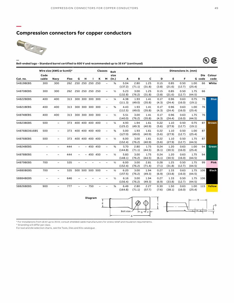
49
Cat. no.
Wire size (AWG or kcmil)* Classes Bolt size (in.)
Dimensions in. (mm)
Die code
Colour code
Code cable Navy Flex G H I K M A B C D E F G
54819BEBS 300 300 262 250 250 250 250 – 3⁄8 5.04 (137.2)
2.80 (71.1)
1.25 (31.8)
0.15 (3.8)
0.85 (21.6)
0.50 (12.7)
1.00 (25.4)
66 White
54870BEBS 300 300 262 250 250 250 250 – 1⁄2 5.23 (132.8)
3.00 (76.2)
1.25 (31.8)
0.15 (3.8)
0.85 (21.6)
0.50 (12.7)
1.75 (44.5)
66
54822BEBS 400 400 313 300 300 300 300 – 1⁄4 4.38 (111.3)
1.93 (49.0)
1.41 (35.8)
0.17 (4.3)
0.96 (24.4)
0.63 (16.0)
0.75 (19.1)
76 Blue
54821BEBS 400 400 313 300 300 300 300 – 3⁄8 4.43 (112.5)
1.93 (49.0)
1.41 (35.8)
0.17 (4.3)
0.96 (24.4)
0.63 (16.0)
1.00 (25.4)
76
54874BEBS 400 400 313 300 300 300 300 – 1⁄2 5.51 (140.0)
3.00 (76.2)
1.41 (35.8)
0.17 (4.3)
0.96 (24.4)
0.63 (16.0)
1.75 (44.5)
76
54823BEBS 500 – 373 400 400 400 400 – 1⁄4 4.93 (125.2)
1.94 (49.3)
1.61 (40.9)
0.22 (5.6)
1.10 (27.9)
0.50 (12.7)
0.75 (19.1)
87 Brown
54876BE0616BS 500 – 373 400 400 400 400 – 3⁄8 5.00 (127.0)
1.93 (49.0)
1.61 (40.9)
0.22 (5.6)
1.10 (27.9)
0.50 (12.7)
1.00 (25.4)
87
54876BEBS 500 – 373 400 400 400 400 – 1⁄2 6.00 (152.4)
3.00 (76.2)
1.61 (40.9)
0.22 (5.6)
1.10 (27.9)
0.50 (12.7)
1.75 (44.5)
87
54824BEBS – – 444 – – 450 450 – 3⁄8 5.70 (144.8)
2.80 (71.1)
1.75 (44.5)
0.24 (6.1)
1.20 (30.5)
0.63 (16.0)
1.00 (25.4)
94 Green
54878BEBS – – 444 – – 450 450 – 1⁄2 5.83 (148.1)
3.00 (76.2)
1.75 (44.5)
0.24 (6.1)
1.20 (30.5)
0.63 (16.0)
1.75 (44.5)
94
54879BEBS 700 – 535 – – – – – 1⁄2 6.00 (152.4)
3.00 (76.2)
2.81 (71.4)
0.28 (7.1)
1.25 (31.8)
0.50 (12.7)
1.75 (44.5)
99 Pink
54880BEBS 700 – 535 500 500 500 500 – 1⁄2 6.20 (157.5)
3.00 (76.2)
1.94 (49.3)
0.27 (6.9)
1.33 (33.8)
0.63 (16.0)
1.75 (44.5)
106 Black
58884BEBS – – 646 – – – – – 1⁄2 6.16 (156.4)
3.00 (76.2)
1.94 (49.3)
0.27 (6.9)
1.33 (33.8)
0.50 (12.7)
1.75 (44.5)
106
58826BEBS 900 – 777 – – 750 – – 3⁄8 6.49 (164.8)
2.80 (71.1)
2.27 (57.7)
0.30 (7.6)
1.50 (38.1)
0.63 (16.0)
1.00 (25.4)
115 Yellow
—Compression connectors for copper conductors
—Bell-ended lugs – Standard barrel certified to 600 V and recommended up to 35 kV¥ (continued)
¥ For installations from 16 kV up to 35 kV, consult shielded cable manufacturers for stress relief and insulation requirements.* Stranding will differ per class.For tool and die selection charts, see the Tools, Dies and Kits catalogue.
Diagram
B
D
Bolt Size G F
CE
A
B
D
Bolt Size G F
CE
A
B
DE
A
G F
C
Bolt size
CO M PR E SSI O N CO N N EC TO R S FO R CO PPER CO N D U C TO R S

B1 copy starts here
B2 copy starts here
B3 copy starts here
50 CO LO R- K E Y E D CO M PR E SSI O N CO N N EC TO R S Y S TEM
—Compression connectors for copper conductors
—Two-barrel lugs – Certified to 600 V and recommended up to 35 kV¥
¥ For installations from 16 kV up to 35 kV, consult shielded cable manufacturers for stress relief and insulation requirements.For tool and die selection charts, see the Tools, Dies and Kits catalogue.
Cat. no.
Wire size (AWG or kcmil) Hole size (in.)
Fig.no.
Dimensions in. (mm) Diecode
Colour codeCode cable Flex A W T
256-30695-828 #6 61/24 1⁄4 1 2.94 (74.7) 0.44 (11.2) 0.06 (1.5) 24 Blue
256-30695-1227 #6 61/24 1⁄4 2 3.38 (85.9) 0.44 (11.2) 0.06 (1.5) 24
Figure 2
1.50
TA
W
Hole size 1⁄4" 0.75
Figure 1
60°1.50
TA
Hole size 1⁄4"0.75
W
Diagrams
Material – High-conductivity wrought copperFinish – Electro tin plated

51
—Compression connectors for copper conductors
—Cast copper one-hole lugs heavy-duty — certified to 600 V and recommended up to 35 kV¥
Material – High-conductivity wrought copperFinish – Electro tin plated
Cat. no.
Code cable size
(AWG or kcmil)
Dimensions in. (mm)Bolt size
(in.)Die
codeA B C D F
53104 8 1.43 (36.3) 0.75 (19.1) 0.50 (12.7) 0.12 (3.0) 0.28 (7.1) #10 29
53105 6 1.43 (36.3) 0.75 (19.1) 0.50 (12.7) 0.12 (3.0) 0.28 (7.1) 1/4 29
53106 4 1.43 (36.3) 0.75 (19.1) 0.50 (12.7) 0.12 (3.0) 0.28 (7.1) 1/4 29
53107 2 2.00 (50.8) 1.00 (25.4) 0.75 (19.1) 0.25 (6.4) 0.43 (10.9) 1/4 45
53108 1 2.00 (50.8) 1.00 (25.4) 0.75 (19.1) 0.25 (6.4) 0.43 (10.9) 1/4 45
53109 1/0 2.00 (50.8) 1.00 (25.4) 0.75 (19.1) 0.25 (6.4) 0.43 (10.9) 3/8 45
53161* 325/24 2.18 (55.4) 0.75 (19.1) 0.81 (20.6) 0.21 (5.3) 0.43 (10.9) 3/8 54
53110 2/0 2.63 (66.8) 1.25 (31.8) 1.00 (25.4) 0.28 (7.1) 0.53 (13.5) 3/8 66
53111 3/0 2.63 (66.8) 1.25 (31.8) 1.00 (25.4) 0.28 (7.1) 0.53 (13.5) 3/8 66
53112 4/0 2.63 (66.8) 1.25 (31.8) 1.00 (25.4) 0.28 (7.1) 0.53 (13.5) 3/8 66
53165* 650/24 3.06 (91.4) 1.38 (35.1) 1.18 (30.0) 0.31 (7.9) 0.75 (19.1) 1/2 76
53113 250 kcmil 3.06 (91.4) 1.50 (38.1) 1.18 (30.0) 0.31 (7.9) 0.75 (19.1) 1/2 76
53114 300 kcmil 3.06 (91.4) 1.50 (38.1) 1.18 (30.0) 0.31 (7.9) 0.75 (19.1) 1/2 76
53115 350 kcmil 3.81 (96.8) 2.00 (50.8) 1.38 (35.1) 0.38 (9.7) 0.81 (20.6) 1/2 99
53116 400 kcmil 3.81 (96.8) 2.00 (50.8) 1.38 (35.1) 0.38 (9.7) 0.81 (20.6) 1/2 99
53118 500 kcmil 3.81 (96.8) 2.00 (50.8) 1.38 (35.1) 0.38 (9.7) 0.81 (20.6) 1/2 99
53168* 1,100/24 3.81 (96.8) 1.63 (41.4) 1.63 (41.4) 0.40 (10.2) 0.88 (22.4) 1/2 107
53169* 1,325/24 3.81 (96.8) 1.63 (41.4) 1.63 (41.4) 0.40 (10.2) 0.88 (22.4) 1/2 107
53123 750 kcmil 4.18 (106.2) 2.12 (53.8) 1.63 (41.4) 0.43 (10.9) 1.00 (25.4) 1/2 112
53173* 2,750/24 5.06 (142.2) 1.88 (47.8) 2.12 (53.8) 0.56 (14.2) 1.18 (30.0) 1/2 150
Bolt size
E C
F
A
B
D
Diagrams
¥ For installations from 16 kV up to 35 kV, consult shielded cable manufacturers for stress relief and insulation requirements.* Not UL Listed and CSA non applicable.For tool and die selection charts, see the Tools, Dies and Kits catalogue.
CO M PR E SSI O N CO N N EC TO R S FO R CO PPER CO N D U C TO R S

B1 copy starts here
B2 copy starts here
B3 copy starts here
52 CO LO R- K E Y E D CO M PR E SSI O N CO N N EC TO R S Y S TEM
Cat. no.
Code cable size (AWG
or kcmil)
Bolt size (in.)
Dimensions in. (mm)
Diecode
No. of crimps
A B C D E F H12
ton15
ton40
ton
256-30695-1055 #14–10 1⁄4 2.00 (50.8) 1.31 (33.3) 0.50 (12.7) 0.12 (3.0) 0.38 (9.7) 0.25 (6.4) 0.63–0.75 (16.0–19.1)
29 1 1 1
53204 #8 1⁄4 2.00 (50.8) 1.31 (33.3) 0.50 (12.7) 0.09 (2.3) 0.38 (9.7) 0.25 (6.4) 0.63 (16.0) 29 1 1 1
53205 #8 1⁄4 2.00 (50.8) 1.31 (33.3) 0.50 (12.7) 0.12 (3.0) 0.38 (9.7) 0.25 (6.4) 0.63 (16.0) 29 1 1 1
53206 #4 1⁄4 2.00 (50.8) 1.31 (33.3) 0.50 (12.7) 0.12 (3.0) 0.38 (9.7) 0.25 (6.4) 0.63 (16.0) 29 1 1 1
53207 #2 1⁄4 3.00 (76.2) 2.00 (50.8) 0.75 (19.1) 0.12 (3.0) 0.59 (15.0) 0.50 (12.7) 0.75 (19.1) 45 1 1 1
53208 #1 1⁄4 3.00 (76.2) 2.00 (50.8) 0.75 (19.1) 0.25 (6.4) 0.59 (15.0) 0.50 (12.7) 1.00 (25.4) 45 1 1 1
53209 1/0 3⁄8 3.00 (76.2) 2.00 (50.8) 0.75 (19.1) 0.25 (6.4) 0.59 (15.0) 0.50 (12.7) 1.00 (25.4) 45 1 1 1
53210 2/0 3⁄8 4.31 (109.5) 3.00 (76.2) 0.75 (19.1) 0.18 (4.6) 0.84 (21.3) 0.63 (16.0) 1.75 (44.5) 66 1 1 1
53211 3/0 1⁄2 4.31 (109.5) 3.00 (76.2) 1.00 (25.4) 0.28 (7.1) 0.84 (21.3) 0.63 (16.0) 1.75 (44.5) 66 1 1 1
53212 4/0 1⁄2 4.31 (109.5) 3.00 (76.2) 1.00 (25.4) 0.28 (7.1) 0.84 (21.3) 0.63 (16.0) 1.75 (44.5) 66 1 1 1
53213 250 1⁄2 4.56 (115.8) 3.00 (76.2) 1.18 (30.0) 0.18 (4.6) 0.93 (23.6) 0.63 (16.0) 1.75 (44.5) 76 1 1 1
53214 300 1⁄2 4.56 (115.8) 3.00 (76.2) 1.18 (30.0) 0.31 (7.9) 0.93 (23.6) 0.63 (16.0) 1.75 (44.5) 76 1 1 1
53215 350 1⁄2 5.31 (134.9) 3.50 (88.9) 1.38 (35.1) 0.25 (6.4) 1.21 (30.7) 0.63 (16.0) 1.75 (44.5) 99 2 1 1
53216 400 1⁄2 5.31 (134.9) 3.50 (88.9) 1.38 (35.1) 0.38 (9.7) 1.21 (30.7) 0.63 (16.0) 1.75 (44.5) 99 2 1 1
53218 500 1⁄2 5.31 (134.9) 3.50 (88.9) 1.38 (35.1) 0.38 (9.7) 1.21 (30.7) 0.63 (16.0) 1.75 (44.5) 99 2 1 1
53220M 600 1⁄2 5.31 (134.9) 3.50 (88.9) 1.63 (41.4) 0.53 (13.5) 1.35 (34.3) 0.63 (16.0) 1.75 (44.5) 112 2 1 1
53222M 700 1⁄2 5.31 (134.9) 3.50 (88.9) 1.63 (41.4) 0.03 (0.8) ± 1.35 (34.3) 0.63 (16.0) 1.75 (44.5) 112 2 1 1
53223M 750 1⁄2 5.31 (134.9) 3.50 (88.9) 1.63 (41.4) 0.03 (0.8) ± 1.35 (34.3) 0.63 (16.0) 1.75 (44.5) 112 2 1 1
53269• 1,325/24 1⁄2 5.50 (139.7) 3.50 (88.9) 1.63 (41.4) 0.40 (10.2) 1.35 (34.3) 0.63 (16.0) 1.75 (44.5) 107 2 1 1
53224 800 1⁄2 6.00 (152.4) 3.50 (88.9) 1.88 (47.8) 0.31 (7.9) 1.56 (39.6) 0.63 (16.0) 1.75 (44.5) 130 – 1 1
53226 900 1⁄2 6.00 (152.4) 3.50 (88.9) 1.88 (47.8) 0.46 (11.7) 1.56 (39.6) 0.63 (16.0) 1.75 (44.5) 130 – 1 1
53228 1000 1⁄2 6.00 (152.4) 3.50 (88.9) 1.88 (47.8) 0.46 (11.7) 1.56 (39.6) 0.63 (16.0) 1.75 (44.5) 130 – 1 1
53273• 1,100 2,750/24
1⁄2 6.19 (157.2) 3.50 (88.9) 2.12 (53.8) 0.56 (14.2) 1.90 (28.3) 0.63 (16.0) 1.75 (44.5) 150 or 150H
– – –
53233 1,500 1⁄2 6.25 (158.8) 3.50 (88.9) 2.25 (57.2) 0.50 (12.7) 1.90 (28.3) 0.63 (16.0) 1.75 (44.5) 150 – 1 1
53233L 1,500 1⁄2 7.31 (185.7) 3.12 (79.2) 2.00 (50.8) 0.50 (12.7) 1.88 (47.8) 0.63 (16.0) 1.75 (44.5) 150 – 1 –
53432L•* 1,500 1⁄2 7.31 (185.7) 3.12 (79.2) 3.00 (76.2) 0.50 (12.7) 1.88 (47.8) 0.63 (16.0) 1.75 (44.5) 150 – 1 –
251-30485-1275 1,250 9 ⁄16 6.19 (157.2) 3.50 (88.9) 2.12 (53.8) 0.56 (14.2) 1.90 (48.3) 0.63 (16.0) 1.75 (44.5) 150 – – –
251-30485-1211 1,750 – 6.38 (162.1) 3.12 (79.2) 3.00 (76.2) 0.50 (12.7) 2.18 (55.4) – – 175 – – 2 (fig. 2)
251-30485-1212 1,750 – 6.38 (162.1) 3.12 (79.2) 2.25 (57.2) 0.50 (12.7) 2.18 (55.4) – – 175 – – 2 (fig. 1)
53239 2,000 169/110
1⁄2 6.19 (157.2) 3.50 (88.9) 2.75 (69.9) 0.50 (12.7) 2.18 (55.4) 0.63 (16.0) 0.63 (16.0) 175 – – –
53239L 178/0.104 2,000
169/0.110
1⁄2 7.31 (185.7) 3.12 (79.2) 2.25 (57.2) 0.50 (12.7) 2.46 (62.5) 0.63 (16.0) 0.63 (16.0) 175 – – –
53439L•* 178/0.104 2,000
1⁄2 7.31 (185.7) 3.12 (79.2) 3.00 (76.2) 0.50 (12.7) 2.18 (55.4) 0.63 (16.0) 0.63 (16.0) 175 – –11421 die
—Compression connectors for copper conductors
—Cast copper two-hole lugs for code copper cable – Certified to 600 V and recommended up to 35 kV¥
¥ For installations from 16 kV up to 35 kV, consult shielded cable manufacturers for stress relief and insulation requirements.* Heavy-duty copper lugs for flexible strand cables 600 V not UL or CSA listed.• CSA not applicable.For tool and die selection charts, see the Tools, Dies and Kits catalogue.
Material – High-conductivity wrought copperFinish – Electro tin plated
Bolt Size
D
B
A
E
H F
C
E C
H
Figure 1
Figure 2
Bolt Size
D
B
A
E
H F
C
E C
H
Figure 1
Figure 2
Diagrams
FH
CE
Bolt sizeFigure 1
A
B
D
C
H
E
Figure 2

53
Cat. no.Cable
size
Dimensions in. (mm) Approx. dia. E
in. (mm)
Bolt size in. (mm)
A B C D F G HDie
code
MD37 37/24 2.44 (62.0) 1.75 (44.5) 0.59 (15.0) 0.16 (4.1) 0.38 (9.7) 0.38 (9.7) 0.31 (7.9) 0.88 (24.4) 26
MDD61 61/24 2.44 (62.0) 1.75 (44.5) 0.59 (15.0) 0.16 (4.1) 0.38 (9.7) 0.38 (9.7) 0.31 (7.9) 0.88 (24.4) 26
MD 105 105/24 2.63 (66.8) 1.75 (44.5) 0.59 (15.0) 0.16 (4.1) 0.44 (11.2) 0.38 (9.7) 0.31 (7.9) 0.88 (24.4) 33
MD 105 91/24 2.63 (66.8) 1.75 (44.5) 0.59 (15.0) 0.16 (4.1) 0.44 (11.2) 0.38 (9.7) 0.31 (7.9) 0.88 (24.4) 33
MD 125 125/24 2.63 (66.8) 1.75 (44.5) 0.59 (15.0) 0.20 (5.2) 0.44 (11.2) 0.38 (9.7) 0.31 (7.9) 0.88 (24.4) 33
MD 150 150/24 2.06 (52.3) 1.88 (47.8) 0.59 (15.0) 0.20 (5.2) 0.63 (16.0) 0.44 (11.2) 0.31 (7.9) 0.88 (24.4) 45
MD 175 175/24 2.06 (52.3) 1.88 (47.8) 0.59 (15.0) 0.20 (5.2) 0.63 (16.0) 0.44 (11.2) 0.31 (7.9) 0.88 (24.4) 45
MD 225 225/24 3.00 (76.2) 1.88 (47.8) 0.69 (17.5) 0.20 (5.2) 0.72 (18.3) 0.44 (11.2) 0.31 (7.9) 0.88 (24.4) 60
MD 275 275/24 3.00 (76.2) 1.88 (47.8) 0.69 (17.5) 0.20 (5.2) 0.72 (18.3) 0.44 (11.2) 0.31 (7.9) 0.88 (24.4) 60
MD 325 325/24 3.00 (76.2) 1.88 (47.8) 0.69 (17.5) 0.20 (5.2) 0.72 (18.3) 0.44 (11.2) 0.31 (7.9) 0.88 (24.4) 60
MD 375 375/24 3.13 (79.5) 2.00 (50.8) 0.78 (19.8) 0.20 (5.2) 0.72 (18.3) 0.44 (11.2) 0.31 (7.9) 0.88 (24.4) 60
MD 450 450/24 3.13 (79.5) 2.00 (50.8) 0.78 (19.8) 0.20 (5.2) 0.72 (18.3) 0.44 (11.2) 0.31 (7.9) 0.88 (24.4) 60
MD 550 550/24 3.19 (81.0) 1.88 (47.8) 0.94 (23.9) 0.20 (5.2) 1.00 (25.4) 0.44 (11.2) 0.31 (7.9) 0.88 (24.4) 76
MD 650 650/24 3.19 (81.0) 1.88 (47.8) 0.94 (23.9) 0.20 (5.2) 1.00 (25.4) 0.44 (11.2) 0.31 (7.9) 0.88 (24.4) 76
MD 775 775/24 3.19 (81.0) 1.88 (47.8) 0.94 (23.9) 0.38 (9.5) 1.00 (25.4) 0.44 (11.2) 0.31 (7.9) 0.88 (24.4) 76
MD 925 925/24 3.75 (95.3) 2.06 (52.3) 1.13 (28.7) 0.38 (9.5) 1.16 (29.5) 0.44 (11.2) 0.38 (9.7) 1.00 (25.4) 87
MD 1100 1,100/24 3.75 (95.3) 2.06 (52.3) 1.34 (34.0) 0.38 (9.5) 1.38 (35.1) 0.44 (11.2) 0.38 (9.7) 1.00 (25.4) 107
MD 1325 1,325/24 3.78 (96.0) 2.09 (53.3) 1.16 (29.5) 0.38 (9.5) 1.75 (44.5) 0.44 (11.2) 0.38 (9.7) 1.00 (25.4) 107
MD 1600 1,600/24 3.75 (95.3) 2.06 (52.3) 1.34 (34.0) 0.38 (9.5) 1.38 (35.1) 0.44 (11.2) 0.38 (9.7) 1.00 (25.4) 107
MD 1925* 1,925/24 4.06 (103.1) 2.09 (53.3) 1.34 (34.0) 0.38 (9.5) 1.50 (38.1) 0.44 (11.2) 0.38 (9.7) 1.00 (25.4) 115
MD 2300 2,300/24 4.38 (111.3) 2.13 (54.1) 1.59 (40.4) 0.38 (9.5) 1.66 (42.2) 0.44 (11.2) 0.38 (9.7) 1.00 (25.4) 130
—Compression connectors for copper conductors
—ABB method – Traction motor disconnect lugs for diesel-electric locomotives
Note: some parts may not be current on the system. Consult your regional sales office for informations.Tooling: all hydraulic tools 12 tons and up.For use in mechanically splicing traction motor wires. MES Flex (B) and DLU.* Supplied with elongated bolt hole.
Material – Cast copper
G
CE
H FA
B
D
g l
k
$
G
CE
H FA
B
D
g l
k
$
G
CE
H FA
B
D
g l
k
$
Diagrams
FH
C
A
B
D
g
E
$
1 k
CO M PR E SSI O N CO N N EC TO R S FO R CO PPER CO N D U C TO R S
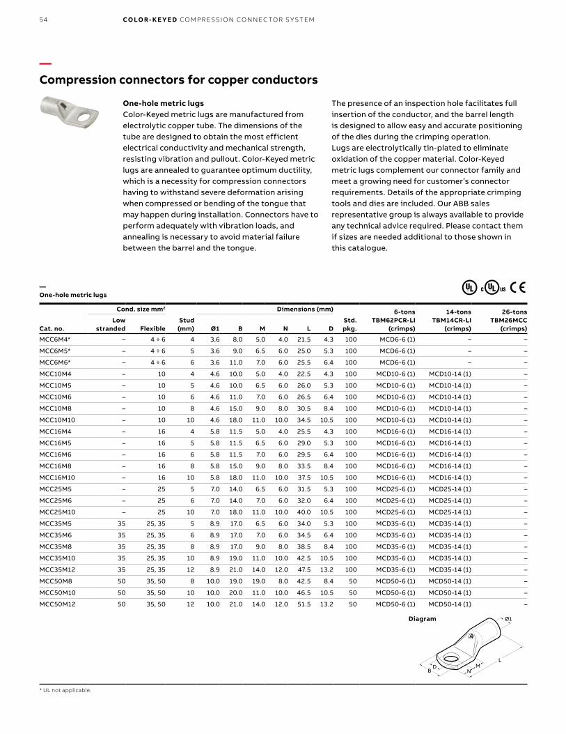
B1 copy starts here
B2 copy starts here
B3 copy starts here
54 CO LO R- K E Y E D CO M PR E SSI O N CO N N EC TO R S Y S TEM
Cat. no.
Cond. size mm2
Stud (mm)
Dimensions (mm)
Std. pkg.
6-tons TBM62PCR-LI
(crimps)
14-tons TBM14CR-LI
(crimps)
26-tons TBM26MCC
(crimps)Low
stranded Flexible Ø1 B M N L D
MCC6M4* – 4 ÷ 6 4 3.6 8.0 5.0 4.0 21.5 4.3 100 MCD6-6 (1) – –
MCC6M5* – 4 ÷ 6 5 3.6 9.0 6.5 6.0 25.0 5.3 100 MCD6-6 (1) – –
MCC6M6* – 4 ÷ 6 6 3.6 11.0 7.0 6.0 25.5 6.4 100 MCD6-6 (1) – –
MCC10M4 – 10 4 4.6 10.0 5.0 4.0 22.5 4.3 100 MCD10-6 (1) MCD10-14 (1) –
MCC10M5 – 10 5 4.6 10.0 6.5 6.0 26.0 5.3 100 MCD10-6 (1) MCD10-14 (1) –
MCC10M6 – 10 6 4.6 11.0 7.0 6.0 26.5 6.4 100 MCD10-6 (1) MCD10-14 (1) –
MCC10M8 – 10 8 4.6 15.0 9.0 8.0 30.5 8.4 100 MCD10-6 (1) MCD10-14 (1) –
MCC10M10 – 10 10 4.6 18.0 11.0 10.0 34.5 10.5 100 MCD10-6 (1) MCD10-14 (1) –
MCC16M4 – 16 4 5.8 11.5 5.0 4.0 25.5 4.3 100 MCD16-6 (1) MCD16-14 (1) –
MCC16M5 – 16 5 5.8 11.5 6.5 6.0 29.0 5.3 100 MCD16-6 (1) MCD16-14 (1) –
MCC16M6 – 16 6 5.8 11.5 7.0 6.0 29.5 6.4 100 MCD16-6 (1) MCD16-14 (1) –
MCC16M8 – 16 8 5.8 15.0 9.0 8.0 33.5 8.4 100 MCD16-6 (1) MCD16-14 (1) –
MCC16M10 – 16 10 5.8 18.0 11.0 10.0 37.5 10.5 100 MCD16-6 (1) MCD16-14 (1) –
MCC25M5 – 25 5 7.0 14.0 6.5 6.0 31.5 5.3 100 MCD25-6 (1) MCD25-14 (1) –
MCC25M6 – 25 6 7.0 14.0 7.0 6.0 32.0 6.4 100 MCD25-6 (1) MCD25-14 (1) –
MCC25M10 – 25 10 7.0 18.0 11.0 10.0 40.0 10.5 100 MCD25-6 (1) MCD25-14 (1) –
MCC35M5 35 25, 35 5 8.9 17.0 6.5 6.0 34.0 5.3 100 MCD35-6 (1) MCD35-14 (1) –
MCC35M6 35 25, 35 6 8.9 17.0 7.0 6.0 34.5 6.4 100 MCD35-6 (1) MCD35-14 (1) –
MCC35M8 35 25, 35 8 8.9 17.0 9.0 8.0 38.5 8.4 100 MCD35-6 (1) MCD35-14 (1) –
MCC35M10 35 25, 35 10 8.9 19.0 11.0 10.0 42.5 10.5 100 MCD35-6 (1) MCD35-14 (1) –
MCC35M12 35 25, 35 12 8.9 21.0 14.0 12.0 47.5 13.2 100 MCD35-6 (1) MCD35-14 (1) –
MCC50M8 50 35, 50 8 10.0 19.0 19.0 8.0 42.5 8.4 50 MCD50-6 (1) MCD50-14 (1) –
MCC50M10 50 35, 50 10 10.0 20.0 11.0 10.0 46.5 10.5 50 MCD50-6 (1) MCD50-14 (1) –
MCC50M12 50 35, 50 12 10.0 21.0 14.0 12.0 51.5 13.2 50 MCD50-6 (1) MCD50-14 (1) –
—Compression connectors for copper conductors
—One-hole metric lugs
* UL not applicable.
Diagram
One-hole metric lugsColor-Keyed metric lugs are manufactured from electrolytic copper tube. The dimensions of the tube are designed to obtain the most efficient electrical conductivity and mechanical strength, resisting vibration and pullout. Color-Keyed metric lugs are annealed to guarantee optimum ductility, which is a necessity for compression connectors having to withstand severe deformation arising when compressed or bending of the tongue that may happen during installation. Connectors have to perform adequately with vibration loads, and annealing is necessary to avoid material failure between the barrel and the tongue.
The presence of an inspection hole facilitates full insertion of the conductor, and the barrel length is designed to allow easy and accurate positioning of the dies during the crimping operation.Lugs are electrolytically tin-plated to eliminate oxidation of the copper material. Color-Keyed metric lugs complement our connector family and meet a growing need for customer’s connector requirements. Details of the appropriate crimping tools and dies are included. Our ABB sales representative group is always available to provide any technical advice required. Please contact them if sizes are needed additional to those shown in this catalogue.
1Ø1
LM
ND
B
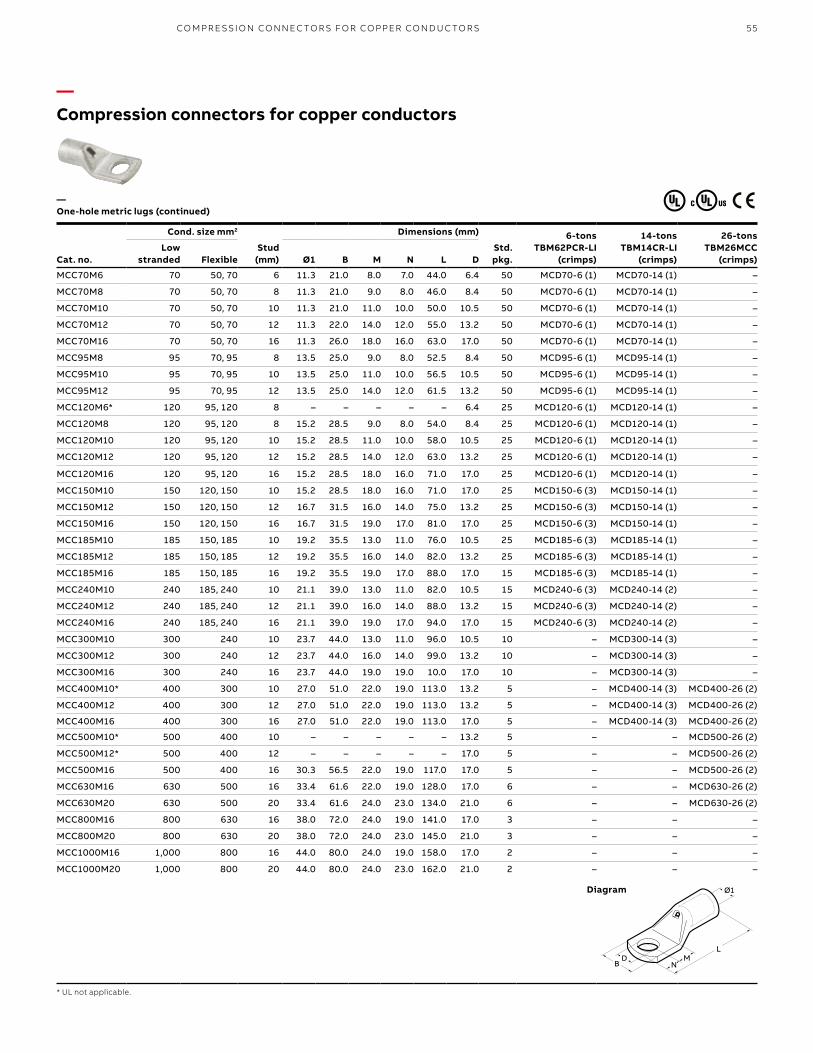
55
Cat. no.
Cond. size mm2
Stud (mm)
Dimensions (mm)
Std. pkg.
6-tons TBM62PCR-LI
(crimps)
14-tons TBM14CR-LI
(crimps)
26-tons TBM26MCC
(crimps)Low
stranded Flexible Ø1 B M N L D
MCC70M6 70 50, 70 6 11.3 21.0 8.0 7.0 44.0 6.4 50 MCD70-6 (1) MCD70-14 (1) –
MCC70M8 70 50, 70 8 11.3 21.0 9.0 8.0 46.0 8.4 50 MCD70-6 (1) MCD70-14 (1) –
MCC70M10 70 50, 70 10 11.3 21.0 11.0 10.0 50.0 10.5 50 MCD70-6 (1) MCD70-14 (1) –
MCC70M12 70 50, 70 12 11.3 22.0 14.0 12.0 55.0 13.2 50 MCD70-6 (1) MCD70-14 (1) –
MCC70M16 70 50, 70 16 11.3 26.0 18.0 16.0 63.0 17.0 50 MCD70-6 (1) MCD70-14 (1) –
MCC95M8 95 70, 95 8 13.5 25.0 9.0 8.0 52.5 8.4 50 MCD95-6 (1) MCD95-14 (1) –
MCC95M10 95 70, 95 10 13.5 25.0 11.0 10.0 56.5 10.5 50 MCD95-6 (1) MCD95-14 (1) –
MCC95M12 95 70, 95 12 13.5 25.0 14.0 12.0 61.5 13.2 50 MCD95-6 (1) MCD95-14 (1) –
MCC120M6* 120 95, 120 8 – – – – – 6.4 25 MCD120-6 (1) MCD120-14 (1) –
MCC120M8 120 95, 120 8 15.2 28.5 9.0 8.0 54.0 8.4 25 MCD120-6 (1) MCD120-14 (1) –
MCC120M10 120 95, 120 10 15.2 28.5 11.0 10.0 58.0 10.5 25 MCD120-6 (1) MCD120-14 (1) –
MCC120M12 120 95, 120 12 15.2 28.5 14.0 12.0 63.0 13.2 25 MCD120-6 (1) MCD120-14 (1) –
MCC120M16 120 95, 120 16 15.2 28.5 18.0 16.0 71.0 17.0 25 MCD120-6 (1) MCD120-14 (1) –
MCC150M10 150 120, 150 10 15.2 28.5 18.0 16.0 71.0 17.0 25 MCD150-6 (3) MCD150-14 (1) –
MCC150M12 150 120, 150 12 16.7 31.5 16.0 14.0 75.0 13.2 25 MCD150-6 (3) MCD150-14 (1) –
MCC150M16 150 120, 150 16 16.7 31.5 19.0 17.0 81.0 17.0 25 MCD150-6 (3) MCD150-14 (1) –
MCC185M10 185 150, 185 10 19.2 35.5 13.0 11.0 76.0 10.5 25 MCD185-6 (3) MCD185-14 (1) –
MCC185M12 185 150, 185 12 19.2 35.5 16.0 14.0 82.0 13.2 25 MCD185-6 (3) MCD185-14 (1) –
MCC185M16 185 150, 185 16 19.2 35.5 19.0 17.0 88.0 17.0 15 MCD185-6 (3) MCD185-14 (1) –
MCC240M10 240 185, 240 10 21.1 39.0 13.0 11.0 82.0 10.5 15 MCD240-6 (3) MCD240-14 (2) –
MCC240M12 240 185, 240 12 21.1 39.0 16.0 14.0 88.0 13.2 15 MCD240-6 (3) MCD240-14 (2) –
MCC240M16 240 185, 240 16 21.1 39.0 19.0 17.0 94.0 17.0 15 MCD240-6 (3) MCD240-14 (2) –
MCC300M10 300 240 10 23.7 44.0 13.0 11.0 96.0 10.5 10 – MCD300-14 (3) –
MCC300M12 300 240 12 23.7 44.0 16.0 14.0 99.0 13.2 10 – MCD300-14 (3) –
MCC300M16 300 240 16 23.7 44.0 19.0 19.0 10.0 17.0 10 – MCD300-14 (3) –
MCC400M10* 400 300 10 27.0 51.0 22.0 19.0 113.0 13.2 5 – MCD400-14 (3) MCD400-26 (2)
MCC400M12 400 300 12 27.0 51.0 22.0 19.0 113.0 13.2 5 – MCD400-14 (3) MCD400-26 (2)
MCC400M16 400 300 16 27.0 51.0 22.0 19.0 113.0 17.0 5 – MCD400-14 (3) MCD400-26 (2)
MCC500M10* 500 400 10 – – – – – 13.2 5 – – MCD500-26 (2)
MCC500M12* 500 400 12 – – – – – 17.0 5 – – MCD500-26 (2)
MCC500M16 500 400 16 30.3 56.5 22.0 19.0 117.0 17.0 5 – – MCD500-26 (2)
MCC630M16 630 500 16 33.4 61.6 22.0 19.0 128.0 17.0 6 – – MCD630-26 (2)
MCC630M20 630 500 20 33.4 61.6 24.0 23.0 134.0 21.0 6 – – MCD630-26 (2)
MCC800M16 800 630 16 38.0 72.0 24.0 19.0 141.0 17.0 3 – – –
MCC800M20 800 630 20 38.0 72.0 24.0 23.0 145.0 21.0 3 – – –
MCC1000M16 1,000 800 16 44.0 80.0 24.0 19.0 158.0 17.0 2 – – –
MCC1000M20 1,000 800 20 44.0 80.0 24.0 23.0 162.0 21.0 2 – – –
—Compression connectors for copper conductors
—One-hole metric lugs (continued)
* UL not applicable.
Diagram 1Ø1
LM
ND
B
CO M PR E SSI O N CO N N EC TO R S FO R CO PPER CO N D U C TO R S
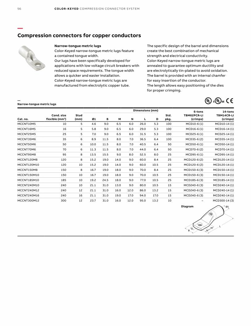
B1 copy starts here
B2 copy starts here
B3 copy starts here
56 CO LO R- K E Y E D CO M PR E SSI O N CO N N EC TO R S Y S TEM
Cat. no.Cond. size
flexible (mm2)Stud
(mm)
Dimensions (mm)
Std. pkg.
6-tons TBM62PCR-LI
(crimps)
14-tons TBM14CR-LI
(crimps)Ø1 B M N L D
MCCNT10M5 10 5 4.6 9.0 6.5 6.0 26.0 5.3 100 MCD10-6 (1) MCD10-14 (1)
MCCNT16M5 16 5 5.8 9.0 6.5 6.0 29.0 5.3 100 MCD16-6 (1) MCD16-14 (1)
MCCNT25M5 25 5 7.0 9.0 6.5 6.0 31.5 5.3 100 MCD25-6 (1) MCD25-14 (1)
MCCNT35M6 35 6 8.9 11.5 8.0 7.0 36.5 6.4 100 MCD35-6 (2) MCD35-14 (1)
MCCNT50M6 50 6 10.0 11.5 8.0 7.0 40.5 6.4 50 MCD50-6 (1) MCD50-14 (1)
MCCNT70M6 70 6 11.3 11.5 8.0 7.0 44.0 6.4 50 MCD70-6 (2) MCD70-14 (1)
MCCNT95M8 95 8 13.5 15.5 9.0 8.0 52.5 8.0 25 MCD95-6 (1) MCD95-14 (1)
MCCNT120M8 120 8 15.2 19.0 14.0 9.0 60.0 8.4 25 MCD120-6 (2) MCD120-14 (1)
MCCNT120M10 120 10 15.2 19.0 14.0 9.0 60.0 10.5 25 MCD120-6 (2) MCD120-14 (1)
MCCNT150M8 150 8 16.7 19.0 18.0 9.0 70.0 8.4 25 MCD150-6 (3) MCD150-14 (1)
MCCNT150M10 150 10 16.7 19.0 18.0 9.0 70.0 10.5 25 MCD150-6 (3) MCD150-14 (1)
MCCNT185M10 185 10 19.2 24.5 18.0 9.0 77.0 10.5 25 MCD185-6 (3) MCD185-14 (1)
MCCNT240M10 240 10 21.1 31.0 13.0 9.0 80.0 10.5 15 MCD240-6 (3) MCD240-14 (1)
MCCNT240M12 240 12 21.1 31.0 16.0 12.0 86.0 13.2 15 MCD240-6 (3) MCD240-14 (1)
MCCNT240M16 240 16 21.1 31.0 19.0 17.0 94.0 17.0 15 MCD240-6 (3) MCD240-14 (1)
MCCNT300M12 300 12 23.7 31.0 16.0 12.0 95.0 13.2 10 – MCD300-14 (3)
—Compression connectors for copper conductors
—Narrow-tongue metric lugs
Diagram
Narrow-tongue metric lugsColor-Keyed narrow-tongue metric lugs feature a contained tongue width.Our lugs have been specifically developed for applications with low voltage circuit breakers with reduced space requirements. The tongue width allows a quicker and easier installation. Color-Keyed narrow-tongue metric lugs are manufactured from electrolytic copper tube.
The specific design of the barrel and dimensions create the best combination of mechanical strength and electrical conductivity.Color-Keyed narrow-tongue metric lugs are annealed to guarantee optimum ductility and are electrolytically tin-plated to avoid oxidation.The barrel is provided with an internal chamfer for easy insertion of the conductor. The length allows easy positioning of the dies for proper crimping.
1Ø1
LM
ND
B

57
Cat. no.
Cond. size (mm2) Dimensions (mm)Std. pkg.
6-tons TBM62PCR-LI
(crimps)
14-tons TBM14CR-LI
(crimps)
26-tons TBM26MCC
(crimps)Low stranded Flexible Ø1 L
MCST1 0.25 ÷ 1.5 0.25 ÷ 1.5 1.8 15 100 – – –
MCST2 1.5 ÷ 2.5 1.5 ÷ 2.5 2.4 15 100 – – –
MCST6 4 ÷ 6 4 ÷ 6 3.6 22 100 MCD6-6 (1 +1) – –
MCST10 10 10 4.6 25 100 MCD10-6 (1 +1) MCD10-14 (1 +1) –
MCST16 16 16 5.8 27 100 MCD16-6 (1 +1) MCD16-14 (1 +1) –
MCST25 25 25 7.0 29 100 MCD25-6 (1 +1) MCD25-14 (1 +1) –
MCST35 35 25 ÷ 35 8.9 332 100 MCD35-6 (1 +1) MCD35-14 (1 +1) –
MCST50 50 35 ÷ 50 10.0 37 50 MCD50-6 (2 +2) MCD50-14 (1 +1) –
MCST70 70 50 ÷ 70 11.3 39 50 MCD70-6 (2 +2) MCD70-14 (1 +1) –
MCST95 95 70 ÷ 95 13.5 43 25 MCD95-6 (2 +2) MCD95-14 (1 +1) –
MCST120 120 95 ÷ 120 15.2 47 25 MCD120-6 (2 +2) MCD120-14 (1 +1) –
MCST150 150 120 ÷ 150 16.7 58 25 MCD150-6 (3 +3) MCD150-14 (1 +1) –
MCST185 185 150 ÷ 85 19.2 64 25 MCD185-6 (3 +3) MCD185-14 (1 +1) –
MCST240 240 185 ÷ 240 21.1 75 15 MCD240-6 (3 +3) MCD240-14 (2 +2) –
MCST300 300 240 23.7 90 10 – MCD300-14 (3 +3) –
MCST400 400 300 27.0 94 5 – MCD400-14 (3 +3) MCD400-26 (2 +2)
MCST500 500 400 30.3 98 6 – – MCD500-26 (2 +2)
MCST630 600 ÷ 630 500 33.4 105 6 – – MCD630-26 (2 +2)
MCST800 800 600 38.0 112 3 – – –
MCST1000 1,000 800 44.0 120 3 – – –
—Compression connectors for copper conductors
—Two-way metric splice connectors
Diagram
Two-way metric splice connectorsColor-Keyed metric splice connectors are designed for joining low voltage conductors.Made of electrolytic copper tube having similar dimensions to the Color-Keyed metric lugs, these connectors are also annealed and electrolytically tin-plated.
They feature an internal chamfer at both ends. For easy insertion of the conductor, a center stop is provided to ensure correct positioning.
Ø1L
CO M PR E SSI O N CO N N EC TO R S FO R CO PPER CO N D U C TO R S

B1 copy starts here
B2 copy starts here
B3 copy starts here
58 CO LO R- K E Y E D CO M PR E SSI O N CO N N EC TO R S Y S TEM
Cat. no.
Code cable (AWG or
kcmil)
Wire size Dimensions in. (mm)Die set cat. no.
Colour codeFlex cable classes G, H, I, K, M* A E
54504 #8 #8 AWG, 37/24, #8 Weld 1.00 (25.4) 0.27 (6.9) 21 Red
54505 #6 #6 AWG, 61/24, #6 Weld, 133/0.014 1.00 (25.4) 0.30 (7.6) 24 Blue
54506 #4 #4 AWG, 91/24, 133/0.0177, 49/0.029 1.00 (25.4) 0.37 (9.4) 29 Grey
54507 #2 125/24, #4 Weld 1.25 (31.8) 0.41 (10.4) 33 Brown
54508 #1 #2 AWG, 150/24, 175/24, #2 Weld, 133/0.0223 1.50 (38.1) 0.47 (11.9) 37 Green
54509 1/0 225/24, #1 Weld, 133/0.0254 1.63 (41.4) 0.52 (13.2) 42 Pink
54510 2/0 1/0 AWG, 275/24, 1/0 Weld, 427/0.0155, 133/0.0282 1.75 (44.5) 0.57 (14.5) 45 Black
54511 3/0 2/0 AWG, 325/24, 2/0 Weld, 133/0.0316, 259/0.0227, 427/0.0177 1.75 (44.5) 0.63 (16.0) 50 Orange
53962 – 375/24, 179 kcmil, 133/0.0355, 259/0.0255, 427/0.0199 1.81 (46.0) 0.70 (17.8) 50
54512 4/0 3/0 AWG, 450/24, 3/0 Weld, 703/0.0154 1.88 (47.8) 0.70 (17.8) 54 Purple
54513 250 4/0 AWG, 550/24, 4/0 Weld, 133/0.0399, 259/0.0286, 637/0.0183 2.25 (57.2) 0.77 (19.6) 62 Yellow
53964 – 4/0 AWG, 550/24, 4/0 Weld, 133/0.0399, 259/0.0286, 637/0.0183 2.13 (54.1) 0.79 (20.1) 62
54514 300 – 2.13 (54.1) 0.83 (21.1) 66 White
54515 350 – 2.25 (57.2) 0.90 (22.9) 71 Red
54516 400 – 2.75 (69.9) 0.93 (23.6) 76 Blue
53968 – 300 kcmil, 775/24 (313 kcmil) 3.00 (76.2) 1.13 (28.7) 87 Brown
54518 500 – 2.75 (69.9) 1.11 (28.2) 87
54520 600 – 3.00 (76.2) 1.18 (30.0) 94 Green
54522-TB 700 – 3.25 (82.6) 1.23 (31.2) 99 Pink
53969 – 1325/24 = 500/535 kcmil, 427/0.0342 3.00 (76.2) 1.24 (31.5) 99
54523-TB 750 – 3.00 (76.2) 1.30 (33.0) 106 Black
54528 1,000 3.63 (92.2) 1.50 (38.1) 125 –
54530 1,250 4.13 (104.9) 1.67 42.4) 140
¥ For installations from 16 kV up to 35 kV, consult shielded cable manufacturers for stress relief and insulation requirements.*Consult your regional sales office for complete list of flex cable class sizes M.For tool and die selection charts, see the Tools, Dies and Kits catalogue.
—Compression connectors for copper conductors
Material – High conductivity wrought copperFinish – Electro tin platedTwo-way connectors provide high pullout values, are easy to insulate and provide a low-resistance connection of high quality and low installed cost.
— Two-way splice connectors – Standard barrel certified to 600 V and recommended up to 35 kV¥
A
E
A
E
Diagram

59
Cat. no.
Code cable (AWG or
kcmil)
Wire size Dimensions in. (mm)Die
codeColour
codeFlex cable classes G, H, I, K, M A E
54804 #8 #8, 37/24 = 14.9 kcmil 1.75 (44.5) 0.27 (6.9) 21 Red
54805 #6 #6, 61/24 = 24.6 kcmil 1.75 (44.5) 0.31 (7.9) 24 Blue
54806 #4 #4, 91/24 = 36.7 kcmil 1.75 (44.5) 0.39 (9.9) 29 Grey
54807 #2 125/24 = 50.4 kcmil 1.88 (47.8) 0.43 (11.0) 33 Brown
54808 #1 #2, 150/24 = 60.5 kcmil, 175/24 = 70.6 kcmil 2.00 (50.8) 0.49 (12.4) 37 Green
54809 1/0 225/24 = 90.8 kcmil 2.00 (50.8) 0.54 (13.7) 42 Pink
54810 2/0 1/0, 275/24 = 111 kcmil 2.13 (54.1) 0.59 (15.0) 45 Black
54811 3/0 2/0, 325/24 = 131 kcmil 2.25 (57.2) 0.65 (16.5) 50 Orange
54812 4/0 450/24 = 182 kcmil 2.75 (69.9) 0.72 (18.3) 54 Purple
54813 250 4/0, 550/24 = 222 kcmil 3.38 (85.9) 0.79 (20.1) 62 Yellow
54814 300 250, 650/24 = 262 kcmil 3.50 (88.9) 0.87 (22.1) 66 White
54815 350 – 3.75 (95.3) 0.95 (24.1) 71 Red
54816 400 775/24 = 313 kcmil 3.75 (95.3) 0.98 (24.9) 76 Blue
54818 500 350, 925/24 = 373 kcmil 4.75 (120.6) 1.11 (28.2) 87 Brown
54820 600 1,100/24 = 444 kcmil 4.25 (108.0) 1.21 (30.7) 94 Green
54823 750 500, 1,325/24 = 535 kcmil 4.75 (120.6) 1.34 (34.0) 106 Black
58524 750 1,600/24 = 646 kcmil 5.00 (127.0) 1.39 (35.3) 106
58526* 900 750, 1,925/24 = 777 kcmil 5.50 (139.7) 1.51 (38.4) 115 Yellow
54828 1,000 – 5.63 (143.0) 1.56 (39.6) 125 –
54833 1,500 – 5.63 (143.0) 1.56 (39.6) 125
54839 2,000 – 7.06 (179.3) 2.13 (54.1) –
¥ For installations from 16 kV up to 35 kV, consult shielded cable manufacturers for stress relief and insulation requirements.For tool and die selection charts, see the Tools, Dies and Kits catalogue.CSA approved standard cable only.
—Compression connectors for copper conductors
Material – High conductivity wrought copperFinish – Electro tin plated
— Two-way splice connectors – Long barrel certified to 600 V and recommended up to 35 kV¥
E DIA.
54 DIE
PURPLE
54 DIE
PURPLE 54 D
IE
PURP
LE
54 D
IE
PURP
LE
T&B
4/0
A
E dia.
Diagram
CO M PR E SSI O N CO N N EC TO R S FO R CO PPER CO N D U C TO R S

B1 copy starts here
B2 copy starts here
B3 copy starts here
60 CO LO R- K E Y E D CO M PR E SSI O N CO N N EC TO R S Y S TEM
Cable size (AWG or kcmil)**
Installing tools 14 and 15-tons*
Dimensions in. (mm) Die setCat. no.
Strip length (in.) Colour codeCat. no. A B
54006-TB #4 2.00 (50.8) 0.37 (9.4) 15CA29R 11⁄2 Grey
54007-TB #2 2.13 (54.1) 0.41 (10.4) 15CA33R 15⁄8 Brown
54008-TB #1 2.25 (57.2) 0.47 (11.9) 15CA37R 15⁄8 Green
54009-TB 1/0 2.38 (60.5) 0.52 (13.2) 15CA42R 13⁄4 Pink
54010 2/0 2.38 (60.5) 0.57 (14.5) 15CA45R 13⁄4 Black
54011 3/0 2.63 (66.8) 0.63 (16.0) 15CA49R 113⁄16 Orange
54012-TB 4/0 2.69 (68.3) 0.69 (17.5) 15CA54R 113⁄16 Purple
54013 250 3.19 (81.0) 0.74 (18.8) 15CA60R 21⁄8 Ruby
54015 350 4.13 (104.9) 0.89 (22.6) 15CA71R 25⁄8 Red
54018 500 4.13 (104.9) 1.06 (40.6) 15CA87R 25⁄8 Brown
54023 750 4.75 (120.7) 1.30 (33.0) 15CA106R 27⁄8 Black
*Cat. no. 15505-TB die adaptor required for TBM15I.** Cable size: Concentric and compact strandings.For tool and die selection charts, see the Tools, Dies and Kits catalogue.
A
B
A
B
Diagram
— Cast–copper two-way splice connectors – heavy-duty certified to 600 V and recommended up to 35 kV¥
Cat. no. Cable size (AWG or kcmil) Die code
53504 #8 29
53505 #6 29
53506 #4 29
53507 #2 45
53508 #1 45
53509 1/0 45
53510 2/0 66
53511 3/0 66
53512 4/0 66
53513 250 76
53515 350 99
53518 500 99
53523 750 112¥ For installations from 16 kV up to 35 kV, consult shielded cable manufacturers for stress relief and insulation requirements.Use hydraulic tools with hex dies 13642M, 13400 and 21940.For tool and die selection charts, see the Tools, Dies and Kits catalogue.
—Compression connectors for copper conductors
Material – Cast copperFinish – Electro tin plated
— Copper two-way splice – Certified to 600 V and recommended up to 15 kV

61
—Compression connectors for copper conductorsConstant O.D. enables faster, easier installation than contoured design
— Cast-copper reducing splices
Cast-copper reducing splices ABB takes the splicing of different-sized conductors to a new level of economy and efficiency with Color-Keyed cast-copper reducing splices. In addition to a lower cost, the key benefit to these splices is in their constant outer diameter. Unlike screw-machined, externally contoured splices, cast-copper reducing splices require no change of tool or die between crimping each end. Just slide each wire easily into the chamfered barrel and use the same Color-Keyed tool and die to crimp both ends. The consistent O.D. also makes these splices faster and easier to insulate with clear heat-shrink wrap than a contoured splice. Sand-cast construction ensures high-tensile strength for heavy-duty applications and tin-plated copper material provides high conductivity and superior corrosion resistance.
• Ideal for telecom (inside office/outside plant), commercial, industrial MRO and any other certified to 600 V and recommended up to 35 kV¥ applications requiring splicing of different-sized conductors.
• Tin-plated, sand-cast copper construction provides superior tensile strength, high conductivity and excellent corrosion resistance.
• Easier to install and insulate than screw-machined, contour-designed reducing splices.
• Constant O.D. saves time on installation by eliminating the need for crimp-tool/die change.
• Fast and simple to insulate with clear or coloured heat-shrink wrap.
• Chamfered barrel facilitates easy wire insertion.
• Compact, low-profile design takes up minimal space in cable tray or wire run.
• Simple installation with Color-Keyed crimp tools (12, 14 and 15 ton).
Cat. No.Cond.1 size
(AWG or kcmil)Cond. 2 size
(AWG or kcmil)Length
in. (mm) Dia.
in. (mm) Die
CodeColour
Code
251-30485-19 4/0 Str. 2 Str. 2.25 (57.2) 0.81 (20.6) 66 White
251-30485-91 500 kcmil Str. 300 kcmil Str. 3.31 (84.1) 0.81 (20.6) 99 Pink
251-30485-229 2/0 Str. 250 kcmil Str. 2.38 (60.5) 0.93 (23.6) 76 Blue
251-30485-247 2 Str. 8 Str. 0.56 (14.2) 0.59 (15.0) 45 Black
251-30485-294 4 Str. 2/0 Str. 2.25 (57.2) 0.84 (21.3) 66 White
251-30485-295 4/0 Str. 4 Str. 2.25 (57.2) 0.81 (20.6) 66
251-30485-331 4/0 Str. 350 kcmil Str. 3.31 (84.1) 0.53 (13.5) 99 Pink
251-30485-445 4/0 Str. 2/0 Str. 2.25 (57.2) 0.81 (20.6) 66 White
251-30485-495 1/0 Str. 2 Str. 1.56 (39.6) 0.59 (15.0) 45 Black
251-30485-610 6 Str. 8 Str. 1.21 (30.7) 0.38 (9.7) 29 Grey
251-30485-611 4 Str. 8 Str. 1.21 (30.7) 0.38 (9.7) 29
251-30485-612 4 Str. 6 Str. 1.21 (30.7) 0.38 (9.7) 29
251-30485-613 2 Str. 6 Str. 1.56 (39.6) 0.59 (15.0) 45 Black
251-30485-640 4/0 Str. 1/0 Str. 2.25 (57.2) 0.81 (20.6) 66 White
251-30485-653 2 Str. 250 kcmil Str. 2.38 (60.5) 0.93 (23.6) 76 Blue
251-30485-739 1/0 Str. 250 kcmil Str. 2.38 (60.5) 0.93 (23.6) 76
251-30485-882 400 kcmil Str. 350 kcmil Str. 3.31 (84.1) 0.53 (13.5) 99 Pink
251-30485-950 1/0 Str. 6 Str. 1.56 (39.6) 0.59 (15.0) 45 Black
251-30485-951 6 Str. 2/0 Str. 2.25 (57.2) 0.84 (21.3) 66 White
251-30485-1027 1/0 Str. 4 Str. 1.56 (39.6) 0.59 (15.0) 45 Black
251-30485-1029 1/0 Str. #12 Str. 1.56 (39.6) 0.57 (14.5) 45
251-30485-1030 10 Str. 4 Str. 1.21 (30.7) 0.38 (9.7) 29 Grey
251-30485-1031 12 Str. 4 Str. 1.21 (30.7) 0.38 (9.7) 29
251-30485-1032 #6 Str. #10 Str. 1.21 (30.7) 0.38 (9.7) 29
251-30485-1033 12 Str. 6 Str. 1.21 (30.7) 0.38 (9.7) 29
251-30485-1034 14 Str. 8 Str. 1.21 (30.7) 0.38 (9.7) 29
251-30485-1035 1 Str. 1/0 Str. 1.56 (39.6) 0.59 (15.0) 45 Black
251-30485-1044 10 Str. 8 Str. 1.21 (30.7) 0.38 (9.7) 29 Grey
251-30485-1045 12 Str. 8 Str. 1.21 (30.7) 0.38 (9.7) 29
251-30485-1085 10 Str. 1/0 Str. 1.56 (39.6) 0.59 (15.0) 45 Black
251-30485-1086 10 Str. 2/0 Str. 2.25 (57.2) 0.84 (21.3) 66 White
251-30485-1087 4 Str. 250 kcmil Str. 2.38 (60.5) 0.93 (23.6) 76 Blue
251-30485-1088 400 kcmil Str. 250 kcmil Str. 3.31 (84.1) 0.53 (13.5) 99 Pink
251-30485-1089 14 Str. 8 Sol. 1.21 (30.7) 0.38 (9.7) 29 Grey
251-30485-1090 12 Str. 8 Sol. 1.21 (30.7) 0.38 (9.7) 29
251-30485-1091 10 Str. 8 Sol. 1.21 (30.7) 0.38 (9.7) 29
251-30485-1092 12 Str. 6 Sol. 1.21 (30.7) 0.38 (9.7) 29
251-30485-1093 8 Str. 6 Sol. 1.21 (30.7) 0.38 (9.7) 29
251-30485-1094 4 Str. 6 Sol. 1.21 (30.7) 0.38 (9.7) 29
251-30485-1095 2 Str. 6 Sol. 1.56 (39.6) 0.59 (15.0) 45 Black
251-30485-1096 12 Str. 4 Sol. 1.21 (30.7) 0.38 (9.7) 29 Grey
251-30485-1097 10 Str. 4 Sol. 1.21 (30.7) 0.38 (9.7) 29
251-30485-1098 8 Str. 4 Sol. 1.21 (30.7) 0.38 (9.7) 29
251-30485-1099 6 Str. 4 Sol. 1.21 (30.7) 0.38 (9.7) 29
251-30485-1100 1/0 Str. 4 Sol. 1.56 (39.6) 0.59 (15.0) 45 Black
251-30485-1130 Cast Copper* 12–4 Str. 1.28 (32.5) 0.38 (9.7) 29
251-30485-1245 1/0 Flex #4 Flex 2.25 (57.2) 0.81 (20.6) 66 White
251-30485-1246 #4 Flex #8 Flex 1.56 (39.6) 0.57 (14.5) 45 Black¥ For installations from 16 kV up to 35 kV, consult shielded cable manufacturers for stress relief and insulation requirements.* Cast copper – field-modifiable special.
CO M PR E SSI O N CO N N EC TO R S FO R CO PPER CO N D U C TO R S

B1 copy starts here
B2 copy starts here
B3 copy starts here
62 CO LO R- K E Y E D CO M PR E SSI O N CO N N EC TO R S Y S TEM
Cat. no.Fig.no.
Colourcode
Wire size (AWG or kcmil)
Crimping information
Hydraulic head
Installing die
# of crimps
Colour code
Die code
Strip length (in.)
Insulating coversMain Branch 1 Branch 2 Branch 3
CHT750350-1F 1 White (750–500)(750)
Flex only
(750–500)(350)
Flex only
– – TBM15I 15620CHF 1 White F 11⁄8 HTC
CHT750350-2 2 Yellow 750–500 (550–500)
750–500(550–350)
– – TBM15I 15620CH 1 Yellow Z 13⁄8 HTC500
CHT75010-3 9 750–500 (550–500)
4/0–1/0(250–1/0)
1 Str. 2–6 AWG (1–8)
2–14 (2–14)
TBM15I 15620CH 1 Z 11⁄8 HTC500
CHT50040-4 2 Brown 500–250 (350–4/0)
500–4/0(350–4/0)
– – TBM15I 15612CH 2 Brown N 11⁄8 HTC500
CHT50010-5 3 500–250 (350–4/0)
250–1/0(4/0–1/0)
1 Str. 2–6 AWG (1–8)
8–14 (8–14)
TBM15I 15612CH 2 N 11⁄8 HTC500
CHT2502-6 2 Purple 250–2 (4/0–2)
250–2(4/0–2)
– – •TBM15I TBM14M
15CA80RCH 1 Purple 80R 13⁄16 HTC40
CHT25014-7 4 250–2 (4/0–2)
2–6 Str./Sol. (2–8)
8–14 (8–14)
– •TBM15I TBM14M
15CA80RCH 1 80R 11⁄8 HTC40
CHT250214-8 5 250–2 (4/0–2)
8–14 (8–14)
8–14 (8–14)
– •TBM15I TBM14M
15CA80RCH 1 80R 11⁄8 HTC40
CHT214-9 6 Brown 2–6 Str./Sol. (2–8)
2–6 Str./Sol. (2–8)
8–14 (8–14)
8–14 (8–14)
•TBM15I TBM14M
13100A
15CA71RCH 3 Brown 71R 7⁄8 HTC40
CHT814-10 7 Green 8–14 (8–14)
8–14 (8–14)
8–14 (8–14)
8–14 (8–14)
•TBM15I TBM14M
13100A
15CA37RCH 1 Green 37R 1⁄2 HTC2S
CHT75040-11 8 Yellow 750 Str. (750–500)
350–4/0 Str. Cu.
& Flex
8–14 (8–14)
8–14 (8–14)
TBM15I 15620CH 1 Yellow Z 11⁄8 HTC500
• Requires adaptor cat. no. 15500-TB when used with hydraulic head TBM15I.Material: Copper per AS ™ designation B-124-55 Alloy 12.For tool and die selection charts, see the Tools, Dies and Kits catalogue.
—Copper H-tap connectors for copper conductors
— Copper H-taps – Certified to 600 V
Material – High conductivity extruded copperFinish – Electro tin plated
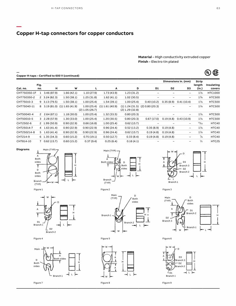
63H -TA P CO N N EC TO R S
—Copper H-tap connectors for copper conductors
Cat. no.Fig. no.
Dimensions in. (mm) Strip length
(in.)Insulating
coversH W L A D D1 D2 D3
CHT750350-1F 1 3.46 (87.9) 1.66 (42.1) 1.10 (27.9) 1.73 (43.9) 1.23 (31.2) – – – 11⁄8 HTC1000
CHT750350-2 2 3.24 (82.3) 1.50 (38.1) 1.25 (31.8) 1.62 (41.1) 1.02 (30.5) – – – 13⁄8 HTC500
CHT75010-3 9 3.13 (79.5) 1.50 (38.1) 1.00 (25.4) 1.54 (39.1) 1.00 (25.4) 0.40 (10.2) 0.35 (8.9) 0.41 (10.4) 11⁄8 HTC500
CHT75040-11 8 3.19 (81.0) (1) 1.65 (41.9) 1.00 (25.4) (2) 1.05 (26.7)
(1) 1.61 (40.9) (1) 1.24 (31.5) (2) 1.29 (32.8)
(2) 0.80 (20.3) – – 11⁄8 HTC500
CHT50040-4 2 2.64 (67.1) 1.18 (30.0) 1.00 (25.4) 1.32 (33.5) 0.80 (20.3) – – – 11⁄8 HTC500
CHT50010-5 3 2.28 (57.9) 1.30 (33.0) 1.00 (25.4) 1.20 (30.5) 0.80 (20.3) 0.67 (17.0) 0.19 (4.8) 0.43 (10.9) 11⁄8 HTC500
CHT2502-6 2 1.99 (50.9) 0.90 (22.9) 0.66 (16.8) 1.00 (25.4) 0.62 (15.7) – – – 13⁄16 HTC40
CHT25014-7 4 1.63 (41.4) 0.90 (22.9) 0.90 (22.9) 0.96 (24.4) 0.52 (13.2) 0.35 (8.9) 0.19 (4.8) – 11⁄8 HTC40
CHT250214-8 5 1.63 (41.4) 0.90 (22.9) 0.90 (22.9) 0.96 (24.4) 0.62 (15.7) 0.19 (4.8) 0.19 (4.8) – 11⁄8 HTC40
CHT214-9 6 1.35 (34.3) 0.60 (15.2) 0.75 (19.1) 0.50 (12.7) 0.33 (8.4) 0.19 (4.8) 0.19 (4.8) – 7⁄8 HTC40
CHT814-10 7 0.62 (15.7) 0.60 (15.2) 0.37 (9.4) 0.25 (6.4) 0.16 (4.1) – – – 1⁄2 HTC2S
Figure 1
Main (TYP)
H
LW
ABoth sides
DBoth sides
Branch (TYP)
Figure 2
Main (TYP)
H
LW
ABoth sides D
Both sides
Branch (TYP)
Figure 3
H
L
W
A
D
D3
Branch 3
Branch 2D2
Branch 11
Figure 6
Main (TYP)
Branch 1
Branch 2D1
A
Branch 3D2
W L
H
D Both sides
Figure 5
D Both sides
Main (TYP)
L
H
W
Branch 1
Branch 2
Figure 4
L
H
W
D
A
Branch 1D1
Branch 2D2
L
H
W
D Both sides
ABoth sides
Main
Branch 1
Figure 7
L
H
W
A
A
W
Figure 8
A
W
L
H
D
Branch 2D2
Branch 3D3
Branch 1D1
Figure 9
Material – High conductivity extruded copperFinish – Electro tin plated
Diagrams
— Copper H-taps – Certified to 600 V (continued)
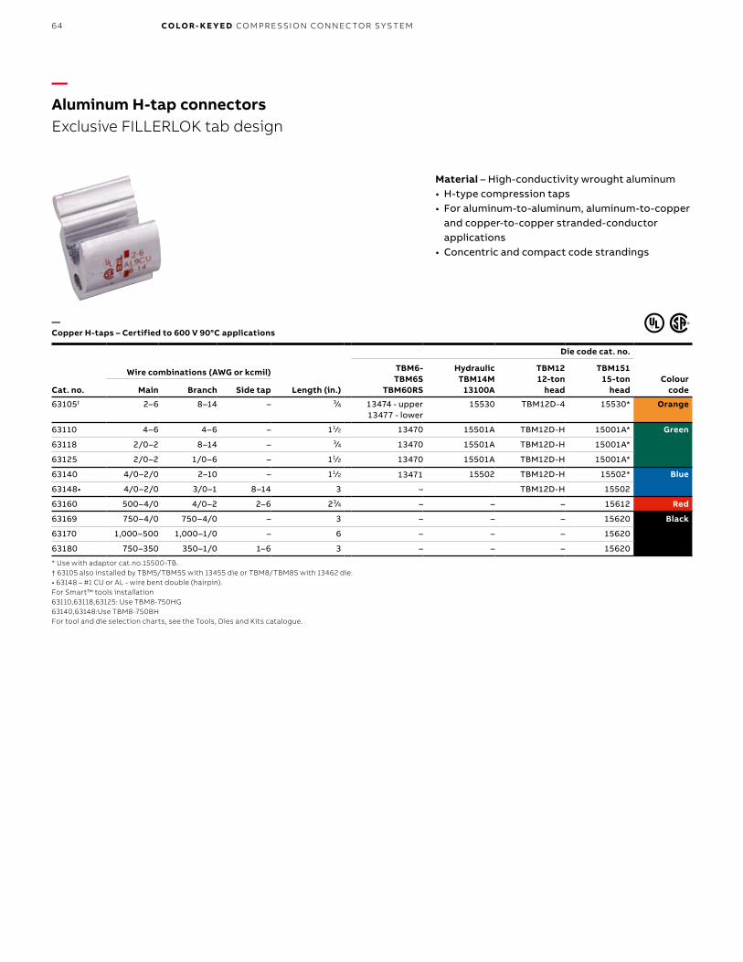
B1 copy starts here
B2 copy starts here
B3 copy starts here
64 CO LO R- K E Y E D CO M PR E SSI O N CO N N EC TO R S Y S TEM
Cat. no.
Die code cat. no.
TBM6- TBM6S
TBM60RS
HydraulicTBM14M
13100A
TBM1212-ton
head
TBM15115-ton
headColour
code
Wire combinations (AWG or kcmil)
Main Branch Side tap Length (in.)
63105† 2–6 8–14 – 3⁄4 13474 - upper13477 - lower
15530 TBM12D-4 15530* Orange
63110 4–6 4–6 – 11⁄2 13470 15501A TBM12D-H 15001A* Green
63118 2/0–2 8–14 – 3⁄4 13470 15501A TBM12D-H 15001A*
63125 2/0–2 1/0–6 – 11⁄2 13470 15501A TBM12D-H 15001A*
63140 4/0–2/0 2–10 – 11⁄2 13471 15502 TBM12D-H 15502* Blue
63148• 4/0–2/0 3/0–1 8–14 3 – TBM12D-H 15502
63160 500–4/0 4/0–2 2–6 23⁄4 – – – 15612 Red
63169 750–4/0 750–4/0 – 3 – – – 15620 Black
63170 1,000–500 1,000–1/0 – 6 – – – 15620
63180 750–350 350–1/0 1–6 3 – – – 15620
* Use with adaptor cat.no.15500-TB.† 63105 also installed by TBM5/TBM5S with 13455 die or TBM8/TBM8S with 13462 die.• 63148 – #1 CU or AL - wire bent double (hairpin).For Smart™ tools installation63110,63118,63125: Use TBM8-750HG 63140,63148:Use TBM8-750BHFor tool and die selection charts, see the Tools, Dies and Kits catalogue.
—Aluminum H-tap connectorsExclusive FILLERLOK tab design
Material – High-conductivity wrought aluminum• H-type compression taps• For aluminum-to-aluminum, aluminum-to-copper
and copper-to-copper stranded-conductor applications
• Concentric and compact code strandings
— Copper H-taps – Certified to 600 V 90°C applications
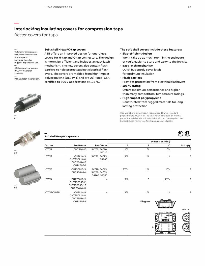
65
—Interlocking insulating covers for compression tapsBetter covers for taps
Soft shell H-tap/C-tap coversABB offers an improved design for one-piece covers for H-tap and C-tap connectors. The design is more size-efficient and includes an easy latch mechanism. The new covers also contain flash barriers to help protect against electrical flash overs. The covers are molded from high-impact polypropylene (UL94V-1) and are UL® listed, CSA certified to 600 V applications at 105 °C.
Cat. no. For H-taps For C-taps
Dimensions (in.)
Std. qty.A B C
HTCV1 CHT814-10 54705, 54710, 54715
13⁄4 7⁄8 9⁄16 5
HTCV2 CHT214-9, CHT250214-8,
CHT25014-7, CHT2502-6
54770, 54775, 54780
33⁄8 11⁄8 1 5
HTCV3 CHT50010-5, CHT50040-4
54740, 54745, 54750, 54755, 54760, 54765
327⁄32 15⁄8 15⁄16 5
HTCV4 CHT75010-3, CHT750350-2,
CHT750350-1F, CHT75040-11
– 55⁄8 2 111⁄16 5
HTCV2CLRFR CHT214-9, CHT250214-8,
CHT25014-7, CHT2502-6
– 33⁄8 13⁄8 1 5
—01 Smaller size requires less space in enclosure.High-impact polypropylene for rugged, dependable use.—02 Clear, polycarbonate (UL94V-0) version available.—03 Easy latch mechanism.
Diagram
—01
—02
—03
— Soft shell H-tap/C-tap covers
The soft shell covers include these features:• Size-efficient design
Won’t take up as much room in the enclosure or vault, easier to store and carry to the job site
• Easy latch mechanism Quick but sturdy cover latch for optimum insulation
• Flash barriers Provides protection from electrical flashovers
• 105 °C rating Offers maximum performance and higher than many competitors’ temperature ratings
• High-impact polypropylene Constructed from rugged materials for long-lasting protection
Also available in clear, impact-resistant and flame-retardant polycarbonate (UL94V-0). The clear version includes an internal pocket for a visible identification label without opening the cover. Contact Customer Service for shipping and availability.
H -TA P CO N N EC TO R S
B
A
C

B1 copy starts here
B2 copy starts here
B3 copy starts here
66 CO LO R- K E Y E D CO M PR E SSI O N CO N N EC TO R S Y S TEM
Cat. no.
Connector range
Dimensions (in.) mm
Colour code
Installing hand tools
Circular mil area Cable combination (AWG)TBM25S/21E
TBM45S TBM8/8S TBM5/5S TBM6 & TBM6S
Min. Max. Min. Max. A EDie
cat. no.Die
cat. no.Die
cat. no. Upper Lower
54610 19,590 27,290 (3) #12 sol. or str.
(2) #10 w/(1) #12 sol. or str.
0.407 (10.3)
0.370 (9.4)
Blue Included – – 13475 13477
54615 31,140 43,400 (3) #10 sol. or str.
(4) #10 sol. or str. 0.407 (10.3)
0.430 (10.9)
Grey Included 13461 13454 13472 13476
54620 49,530 65,560 (3) #8 sol. or str.
(1) #4 w/(2) #10 sol. or str.
0.417 (10.6)
0.475 (12.1)
Brown Included – – 13474 –
54625-TB 66,040 87,130 (4) #8 sol. or str.
(1) #2 str w/(2) #12 sol. or str.
0.479 (12.2)
0.545 (13.8)
Green – – – – –
54630 83,480 99,990 (2) #4 sol. or str.
(2) #4 w/(1) #10 sol. or str.
0.479 (12.2)
0.585 (14.9)
Pink – 13462 13455 13475 13477
54635 99,060 124,220 (6) #8 str. (2) #4 w/(2) #8 sol. or str.
0.762 (19.4)
0.620 (15.7)
Black – – – 13474 –
54640 125,220 166,120 (3) #4 sol. or str.
(3) #4 w/(2) #10 sol. or str.
0.762 (19.4)
0.695 (17.7)
Orange – – – – –
54645-TB 166,960 193,630 (4) #4 sol. or str.
(2) #1 w/(2) #10 sol. or str.
0.824 (20.9)
0.770 (19.6)
Purple – 13463 13456 13475 –
54650 189,190 244,020 (3) #2 str. (2) #1/0 w/(2) #8 str. 0.887 (22.5)
0.830 (21.1)
Yellow – 13463 13456 13473 13476
Hand tools only.For tool and die selection charts, see the Tools, Dies and Kits catalogue.
—Wire joints for copper conductorsAll-around compression ensures high conductivity, low resistance and high pull-out values exceeding CSA requirements
Compression wire joints for copper conductors• Ideal for pigtailing, tapping multiple
conductors or two-way splicing• Form a permanent installation
in minimal space• Easily insulated• Offer lowest installed cost• Made of high-conductivity copper
and electro tin-plated• Colored-coded to dies for positive
matching and compression
— Compression wire joints for copper conductors
A EEA
Diagram
AWG Size
Circular Mil Area
#14 4,107
#12 6,530
#10 10,380
#8 16,510
#6 26,250
#4 41,740
#2 66,370
#1 83,690
1/0 105,500
2/0 133,100
3/0 167,800
4/0 211,600Three-way connector
Two-way connector
Pigtail

67W I R E J O I NTS A N D C A S T CO PPER B US TA P S FO R CO PPER CO N D U C TO R S
—Cast copper bus taps for copper conductorsClamps onto bus bar — no drilling required
— Heavy-duty bus bar taps – Certified to 600 V and recommended up to 35 kV¥ applications
Diagrams
Cat. no.
Wire size (AWG or kcmil)
Fig. no. Busbar width
Dimensions in. (mm) DiecodeCode cable Flex A B C
251-31446-1 1/0 225/24 1 3 6.12 (155.4) 2.28 (57.9) 3.50 (88.9) 66H
251-31446-7 1/0 225/24 1 4 7.12 (180.8) 2.28 (57.9) 4.50 (114.3) 66H
251-31446-13 1/0 225/24 2 5 or 6 9.12 (231.6) 2.28 (57.9) 6.38 (162.1) 66H
251-31446-8 2/0 1/0, 275/24 1 4 7.12 (180.8) 2.28 (57.9) 4.50 (114.3) 66H
251-31446-14 2/0 1/0, 275/24 2 5 or 6 9.12 (231.6) 2.28 (57.9) 6.38 (162.1) 66H
251-31446-23 4/0 450/24 1 3 6.12 (155.4) 2.28 (57.9) 3.50 (88.9) 66H
251-31446-22 4/0 450/24 1 4 7.12 (180.8) 2.28 (57.9) 4.50 (114.3) 66H
251-31446-19 4/0 450/24 2 6 9.12 (231.6) 2.28 (57.9) 6.44 (163.6) 66H
251-31446-29 250 4/0, 550/24 1 3 5.68 (144.3) 2.28 (57.9) 3.38 (85.9) 66H
251-31446-30 250 4/0, 550/24 1 4 7.12 (180.8) 2.28 (57.9) 4.50 (114.3) 66H
251-31446-31 250 4/0, 550/24 1 5 or 6 9.12 (231.6) 2.28 (57.9) 6.38 (162.1) 66H
251-31446-3 350 – 1 3 6.63 (168.4) 2.56 (65.0) 3.50 (88.9) 99H
251-31446-9 350 – 1 4 7.63 (193.8) 2.56 (65.0) 4.50 (114.3) 99H
251-31446-15 350 – 2 5 or 6 9.63 (244.6) 2.56 (65.0) 6.38 (162.1) 99H
251-31446-4 500 350, 925/24 1 3 6.63 (168.4) 2.56 (65.0) 3.50 (88.9) 99H
251-31446-10 500 350, 925/24 1 4 7.63 (193.8) 2.56 (65.0) 4.50 (114.3) 99H
251-31446-16 500 350, 925/24 2 5 or 6 9.63 (244.6) 2.56 (65.0) 6.38 (162.1) 99H
251-31446-17 600 – 2 5 or 6 9.75 (247.7) 2.75 (69.9) 6.38 (162.1) 112H
251-31446-21 700 – 1 6 9.75 (247.7) 2.75 (69.9) 6.44 (163.6) 112H
251-31446-6 750 500, 1,325/24 1 3 6.75 (171.5) 2.75 (69.9) 3.50 (88.9) 112H
251-31446-12 750 500, 1,325/24 2 4 7.75 (196.6) 2.75 (69.9) 4.50 (114.3) 112H
251-31446-18 750 500, 1,325/24 2 5 or 6 9.75 (247.7) 2.75 (69.9) 6.38 (162.1) 112H
251-31446-36 – 750, 1,925/24 2 5 or 6 9.75 (247.7) 2.75 (69.9) 6.44 (163.6) 112H
Styles shown have cable tap on one portion of clamp assembly. Clamp assemblies with cable taps on both portions (top and bottom identical) are also available.These assemblies are identified by adding suffix “AD” to catalogue numbers shown (example: 251-31446-1AD).Only one hydraulic tools with hex crimp dies TBM12.¥ For installations from 16 kV up to 35 kV, consult shielded cable manufacturers for stress relief and insulation requirements.For tool and die selection charts, see the Tools, Dies and Kits catalogue.
Double Cable – Use AD Suffix
Double cable—Use AD suffix
Heavy-duty bus bar taps – certified to 600 V and recommended up to 35 kV¥ applications Material – High-conductivity cast copper alloy Finish – Electro tin platedContact material – Beryllium copper• For bus bars up to 1/4 in. thick, 3–6 in. wide
and code copper cable• Take up less than 11/4 in. of bus bar space• Convex shape of connector tongue exerts great
contact pressure on bus bar• Install with hydraulic tools and hex crimp dies
1-3/8 Approx.
A Approx.
“T” Dim.1/2 Nom. For All
Parts Listed(See Chart)
Bronze Palnut C
3/8-16 CopperPlated Steel
Bolts and NutsBrazed
BApprox.
Figure 1
Figure 1
1-3⁄8 approx.
A approx.
Bronze palnut
Brazed
C
“T” dim. 1⁄2 nom. for all
parts listed (see chart) B approx.
3⁄8-16 Copper plated steel bolts and nuts
C
1"
1-3/8 Approx.A Approx.
“T” Dim.1/2 Nom. For All
Parts Listed(See Chart)
Bronze Palnut
3/8-16 CopperPlated Steel
Bolts and Nuts Brazed
BApprox.
Figure 2
Figure 2
A approx.
Brazed
B approx.
C
1-3⁄8 approx.
Bronze palnut
“T” dim. 1⁄2 nom. for all
parts listed (see chart)
1"
3⁄8-16 Copper plated steel bolts and nuts

B1 copy starts here
B2 copy starts here
B3 copy starts here
68 CO LO R- K E Y E D CO M PR E SSI O N CO N N EC TO R S Y S TEM
One line to one load (two wires) • Complete line of motor lead disconnects for 600
V and 5 kV applications, covering wire range from #16 through 4/0 AWG
• Fast, snap-together assembly offers maximum labor savings
• No need for nuts, bolts and washers or insulating tape – simply slide on reusable boot
• Total assembly fits into tight motor housings• Quick disconnect – no knife cutting of melted
tape, eliminating the risk of accidental cutting of wire insulation, resulting motor downtime and installer exposure
• Meet or exceed electrical and mechanical performance of bolted connections
• Constructed of high-conductivity copper with tin-plating
• Female disconnects equipped with beryllium copper interface band for dependable connections
Cat. no. certified to 600 V Wire size (AWG or
kcmil) Body
sizeColour
codeBoot
insulation
Dimensions in. (mm)Strip
length (in.)
Femaledisconnect
Maledisconnect A B C D E F
MD1614F-0 MD1614M-0 #16–14 0 Blue MDBOOT-0 0.25 (6.4) 0.25 (6.4) 0.63 (16.0) 0.52 (13.2) 0.25 (6.4) 0.13 (3.2) 3⁄8
MD1614F-1 MD1614M-1 #16–14 1 MDBOOT-1 0.38 (9.7) 0.38 (9.7) 0.78 (19.8) 0.75 (19.1) 0.38 (9.7) 0.25 (6.4) 3⁄8
MD1210F-1 MD1210M-1 #12–10 1 Yellow MDBOOT-1 0.38 (9.7) 0.35 (8.9) 0.78 (19.8) 0.75 (19.1) 0.38 (9.7) 0.25 (6.4) 3⁄8
MD1210F-2 MD1210M-2 #12–10 2 MDBOOT-2 0.50 (12.7) 0.50 (12.7) 0.90 (22.9) 1.00 (25.4) 0.50 (12.7) 0.37 (9.4) 3⁄8
MD8F-1 MD8M-1 #8 1 Red MDBOOT-1 0.38 (9.7) 0.38 (9.7) 0.82 (20.8) 0.75 (19.1) 0.38 (9.7) 0.25 (6.4) 7⁄16
MD8F-2 MD8M-2 #8 2 MDBOOT-2 0.50 (12.7) 0.50 (12.7) 0.95 (24.1) 1.00 (25.4) 0.50 (12.7) 0.37 (9.4) 7⁄16
MD6F-1 MD6M-1 #6 1 Blue MDBOOT-1 0.38 (9.7) 0.38 (9.7) 0.88 (22.4) 0.75 (19.1) 0.38 (9.7) 0.25 (6.4) 1⁄2
MD6F-2 MD6M-2 #6 2 MDBOOT-2 0.50 (12.7) 0.50 (12.7) 1.02 (30.5) 1.00 (25.4) 0.50 (12.7) 0.37 (9.4) 1⁄2
MD4F-2 MD4M-2 #4 2 Grey MDBOOT-2 0.50 (12.7) 0.50 (12.7) 1.03 (40.6) 1.00 (25.4) 0.50 (12.7) 0.37 (9.4) 1⁄2
MD2F-2 MD2M-2 #2 2 Brown MDBOOT-2 0.50 (12.7) 0.50 (12.7) 1.09 (48.3) 1.00 (25.4) 0.50 (12.7) 0.37 (9.4) 17⁄32
MD2F-3 MD2M-3 #2 3 MDBOOT-3 0.88 (22.4) 0.88 (22.4) 1.46 (37.1) 1.75 (44.5) 0.88 (22.4) 0.50 (12.7) 17⁄32
MD1F-2 MD1M-2 #1 2 Green MDBOOT-2 0.50 (12.7) 0.50 (12.7) 1.23 (31.2) 1.00 (25.4) 0.50 (12.7) 0.37 (9.4) 9⁄16
MD1F-3 MD1M-3 #1 3 MDBOOT-3 0.88 (22.4) 0.88 (22.4) 1.56 (39.6) 1.75 (44.5) 0.88 (22.4) 0.50 (12.7) 9⁄16
MD10F-3 MD10M-3 1/0 3 Pink MDBOOT-3 0.88 (22.4) 0.88 (22.4) 1.56 (39.6) 1.75 (44.5) 0.88 (22.4) 0.50 (12.7) 9⁄16
MD20F-3 MD20M-3 2/0 3 Black MDBOOT-3 0.88 (22.4) 0.88 (22.4) 1.59 (40.4) 1.75 (44.5) 0.88 (22.4) 0.50 (12.7) 5⁄8
MD30F-3 MD30M-3 3/0 3 Orange MDBOOT-3 0.88 (22.4) 0.88 (22.4) 1.71 (43.4) 1.75 (44.5) 0.88 (22.4) 0.50 (12.7) 11⁄16
MD40F-3 MD40M-3 4/0 3 Purple MDBOOT-3 0.88 (22.4) 0.88 (22.4) 1.81 (46.0) 1.75 (44.5) 0.88 (22.4) 0.50 (12.7) 3⁄4
MD40F-4 MD40M-4 4/0 4 MDBOOT-4 1.25 (31.8) 1.25 (31.8) 2.89 (73.4) 2.69 (68.3) 1.25 (31.8) 0.81 (22.4) –
MD250F-4 MD250M-4 250 4 Yellow MDBOOT-4 1.25 (31.8) 1.25 (31.8) 2.89 (73.4) 2.69 (68.3) 1.25 (31.8) 0.81 (22.4) –
MD350F-4 MD350M-4 350 4 Red MDBOOT-4 1.25 (31.8) 1.25 (31.8) 2.89 (73.4) 2.69 (68.3) 1.25 (31.8) 0.81 (22.4) –
MD500F-4 MD500M-4 500 4 Brown MDBOOT-4 1.25 (31.8) 1.25 (31.8) 2.89 (73.4) 2.69 (68.3) 1.25 (31.8) 0.81 (22.4) –
Kits: page 71For tool and die selection charts, see the Tools, Dies and Kits catalogue.
Male disconnect
D
F
B E
A
C
E
F
DB
A
C
Female disconnect
B E
A
C
B
A
C
E
—Motor pigtail connectorsQuick, reliable change-out of electric motors with no bolting, taping or loose connections
— One line to one load (two wires)
Diagrams
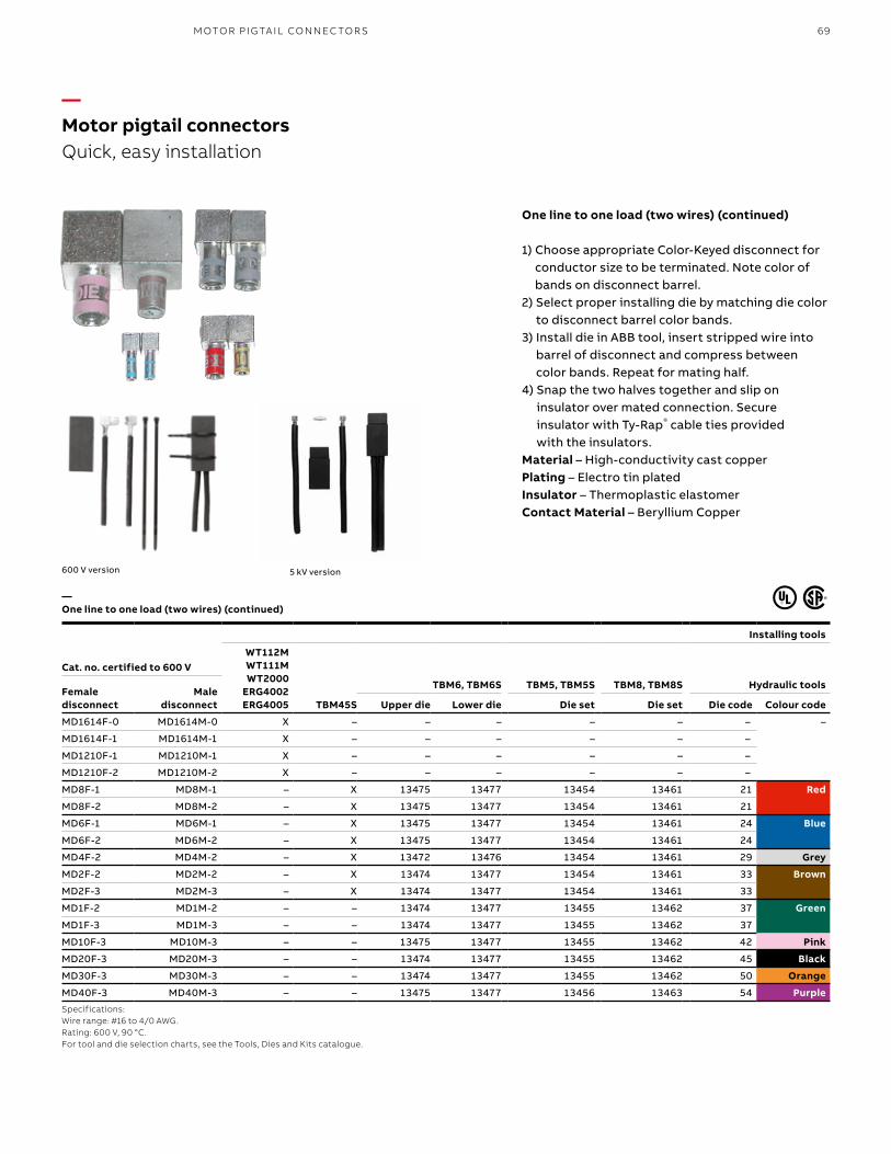
69M OTO R PI G TA I L CO N N EC TO R S
—Motor pigtail connectorsQuick, easy installation
— One line to one load (two wires) (continued)
One line to one load (two wires) (continued)
1) Choose appropriate Color-Keyed disconnect for conductor size to be terminated. Note color of bands on disconnect barrel.
2) Select proper installing die by matching die color to disconnect barrel color bands.
3) Install die in ABB tool, insert stripped wire into barrel of disconnect and compress between color bands. Repeat for mating half.
4) Snap the two halves together and slip on insulator over mated connection. Secure insulator with Ty-Rap® cable ties provided with the insulators.
Material – High-conductivity cast copper Plating – Electro tin platedInsulator – Thermoplastic elastomerContact Material – Beryllium Copper
5 kV version600 V version
Installing tools
Cat. no. certified to 600 VWT112M WT111M WT2000
ERG4002ERG4005 TBM45S
TBM6, TBM6S TBM5, TBM5S TBM8, TBM8S Hydraulic toolsFemale disconnect
Male disconnect Upper die Lower die Die set Die set Die code Colour code
MD1614F-0 MD1614M-0 X – – – – – – –
MD1614F-1 MD1614M-1 X – – – – – –
MD1210F-1 MD1210M-1 X – – – – – –
MD1210F-2 MD1210M-2 X – – – – – –
MD8F-1 MD8M-1 – X 13475 13477 13454 13461 21 Red
MD8F-2 MD8M-2 – X 13475 13477 13454 13461 21
MD6F-1 MD6M-1 – X 13475 13477 13454 13461 24 Blue
MD6F-2 MD6M-2 – X 13475 13477 13454 13461 24
MD4F-2 MD4M-2 – X 13472 13476 13454 13461 29 Grey
MD2F-2 MD2M-2 – X 13474 13477 13454 13461 33 Brown
MD2F-3 MD2M-3 – X 13474 13477 13454 13461 33
MD1F-2 MD1M-2 – – 13474 13477 13455 13462 37 Green
MD1F-3 MD1M-3 – – 13474 13477 13455 13462 37
MD10F-3 MD10M-3 – – 13475 13477 13455 13462 42 Pink
MD20F-3 MD20M-3 – – 13474 13477 13455 13462 45 Black
MD30F-3 MD30M-3 – – 13474 13477 13455 13462 50 Orange
MD40F-3 MD40M-3 – – 13475 13477 13456 13463 54 PurpleSpecifications:Wire range: #16 to 4/0 AWG.Rating: 600 V, 90 °C.For tool and die selection charts, see the Tools, Dies and Kits catalogue.

B1 copy starts here
B2 copy starts here
B3 copy starts here
70 CO LO R- K E Y E D CO M PR E SSI O N CO N N EC TO R S Y S TEM
Cat. no. certified to 600 V
Wire size (AWG)
Body size
Colour code
Boot insulation
Dimensions in. (mm)Strip
length (in.)
Female disconnect
Male disconnect A B C D E F
MD1614F-0 M2D1614M-0 #16–14 AWG 0 Blue MDBOOT-0 0.25 (6.4) 0.25 (6.4) 0.63 (16.0) 0.52 (13.2) 0.25 (6.4) 0.13 (3.3) 3⁄8
MD1614F-1 M2D1614M-1 #16–14 AWG 1 MDBOOT-1 0.38 (9.7) 0.38 (9.7) 0.78 (19.8) 0.75 (19.1) 0.38 (9.7) 0.25 (6.4) 3⁄8
MD1210F-1 M2D1210M-1 #12–10 AWG 1 Yellow M2DBOOT-1 0.38 (9.7) 0.35 (8.9) 0.78 (19.8) 0.75 (19.1) 0.38 (9.7) 0.25 (6.4) 3⁄8
MD1210F-2 M2D1210M-2 #12–10 AWG 2 M2DBOOT-2 0.50 (12.7) 0.50 (12.7) 0.90 (22.9) 1.00 (25.4) 0.50 (12.7) 0.37 (9.4) 3⁄8
MD8F-1 M2D8M-1 #8 AWG 1 Red M2DBOOT-1 0.38 (9.7) 0.38 (9.7) 0.82 (20.8) 0.75 (19.1) 0.38 (9.7) 0.25 (6.4) 7⁄16
MD8F-2 M2D8M-2 #8 AWG 2 M2DBOOT-2 0.50 (12.7) 0.50 (12.7) 0.95 (24.1) 1.00 (25.4) 0.50 (12.7) 0.37 (9.4) 7⁄16
MD6F-1 M2D6M-1 #6 AWG 1 Blue M2DBOOT-1 0.38 (9.7) 0.38 (9.7) 0.88 (22.4) 0.75 (19.1) 0.38 (9.7) 0.25 (6.4) 1⁄2
MD6F-2 M2D6M-2 #6 AWG 2 M2DBOOT-2 0.50 (12.7) 0.50 (12.7) 1.02 (25.9) 1.00 (25.4) 0.50 (12.7) 0.37 (9.4) 1⁄2
MD4F-2 M2D4M-2 #4 AWG 2 Grey M2DBOOT-2 0.50 (12.7) 0.50 (12.7) 1.03 (26.2) 1.00 (25.4) 0.50 (12.7) 0.37 (9.4) 1⁄2
MD2F-2 M2D2M-2 #2 AWG 2 Brown M2DBOOT-2 0.50 (12.7) 0.50 (12.7) 1.09 (27.7) 1.00 (25.4) 0.50 (12.7) 0.37 (9.4) 17⁄32
MD2F-3 M2D2M-3 #2 AWG 3 M2DBOOT-3 0.88 (22.4) 0.88 (22.4) 1.46 (37.1) 1.75 (44.5) 0.88 (22.4) 0.50 (12.7) 17⁄32
MD1F-2 M2D1M-2 #1 AWG 2 Green M2DBOOT-2 0.50 (12.7) 0.50 (12.7) 1.23 (31.2) 1.00 (25.4) 0.50 (12.7) 0.37 (9.4) 9⁄16
MD1F-3 M2D1M-3 #1 AWG 3 M2DBOOT-3 0.88 (22.4) 0.88 (22.4) 1.56 (39.6) 1.75 (44.5) 0.88 (22.4) 0.50 (12.7) 9⁄16
MD10F-3 M2D10M-3 1/0 AWG 3 Pink M2DBOOT-3 0.88 (22.4) 0.88 (22.4) 1.56 (39.6) 1.75 (44.5) 0.88 (22.4) 0.50 (12.7) 9⁄16
MD20F-3 M2D20M-3 2/0 AWG 3 Black M2DBOOT-3 0.88 (22.4) 0.88 (22.4) 1.59 (40.4) 1.75 (44.5) 0.88 (22.4) 0.50 (12.7) 5⁄8
MD30F-3 M2D30M-3 3/0 AWG 3 Orange M2DBOOT-3 0.88 (22.4) 0.88 (22.4) 1.71 (43.4) 1.75 (44.5) 0.88 (22.4) 0.50 (12.7) 11⁄16
MD40F-3 M2D40M-3 4/0 AWG 3 Purple M2DBOOT-3 0.88 (22.4) 0.88 (22.4) 1.81 (46.0) 1.75 (44.5) 0.88 (22.4) 0.50 (12.7) 3⁄4
Operating range: 600 V max., 1000 V max. in signs and fixtures.Listing: UL listed and CSA certified for 12/8 AWG solid copper conductors and stranded copper conductors in the sizes shown.Selection: Always use the same body size when selecting male and female disconnects.For example: to connect a 2 AWG male to an #8 AWG female, select cat. no. M2DM-2 and MD8F-2. Both have body size 2.Insulation: Use insulating boots matching the disconnect body size as indicated in the chart. To protect the connection from moisture and dirt, use sealing compound cat. no. MDBOOT-SEAL.For tool and die selection charts, see the Tools, Dies and Kits catalogue.
One line to two load (three wires) • KON-TOUR™ louvered contact bands• Colour-coded to match installing diesMaterial – High-conductivity wrought copper Finish – Electro tin platedContact material – Beryllium copper
D
F
B
A
CC
A
B
D
F
B E
A
CC
A
B E
—Motor pigtail connectors
— One line to two load (three wires)
Diagrams

71
—Motor pigtail connectors
Cat. no.Wire range
(AWG)
Female disconnect
Cat. no. Colour code
Dimensions in. (mm)Body
sizeL W H
5KVBOOT-2L (connection pin for two female connectors included)
#8 MD8F-2 Red 4.50 (114.3) 2.25 (57.2) 1.44 (36.6) 2
#6 MD6F-2 Blue 4.50 (114.3) 2.25 (57.2) 1.44 (36.6) 2
#4 MD4F-2 Grey 4.50 (114.3) 2.25 (57.2) 1.44 (36.6) 2
#2 MD2F-2 Brown 4.50 (114.3) 2.25 (57.2) 1.44 (36.6) 2
#1 MD1F-2 Green 4.50 (114.3) 2.25 (57.2) 1.44 (36.6) 2
5KVBOOT-3L (connection pin for two female connectors included)
#2 MD2F-3 Brown 4.50 (114.3) 2.25 (57.2) 1.44 (36.6) 3
#1 MD1F-3 Green 4.50 (114.3) 2.25 (57.2) 1.44 (36.6) 3
1/0 MD10F-3 Pink 4.50 (114.3) 2.25 (57.2) 1.44 (36.6) 3
2/0 MD20F-3 Black 4.50 (114.3) 2.25 (57.2) 1.44 (36.6) 3
3/0 MD30F-3 Orange 4.50 (114.3) 2.25 (57.2) 1.44 (36.6) 3
4/0 MD40F-3 Purple 4.50 (114.3) 2.25 (57.2) 1.44 (36.6) 3
CSA and UL non applicable.* Male pin supplied will fit all ranges and combinations of wire sizes per body size.
— 5 kV motor pigtail connectors supplied with boot, pin, silicon gel (two female connectors required)*
Double male pin
4.50
2.25
1.44
Diagrams
Cat. no. DescriptionMDBOOT-SEAL Sealant
For watertight applications, consult your Regional Sales Office for informations.
Sealing for motor-disconnect boots Sealant should be used with ABB motor-disconnect boots: MDBOOT-O, MDBOOT-1, MDBOOT-2 and MDBOOT-3.The cable should be clean and free of grease and other foreign substances. Apply two layers around each cable at the same distance from the connector. Slide the assembly into boot, apply Ty-Rap cable ties and work sealant around wires at end of boot to eliminate voids.
End
Start
Start
End
Diagrams
—Sealing for motor-disconnect boots
Technical specifications• Description: polybutene compound• Application temperature: 4 °C to 38 °C (40 °F to 100 °F)• Service temperature: -40 °C to 82 °C (-40 °F to 180 °F)• Dimensions: width 1 in., thickness 1⁄8 in., length (std. roll)
10 ft., wrapped on release liner• Environmental resistance: resists normal aging process• Chemical resistance: resists acids, bases and alcohols• Dielectric strength: 200 V/mil minimum• Volume resistivity: 1013 ohms/cm• Flame retardancy: passed VO vertical flame test
Cat. no. Size Std. pkg.
2015 5 grams 100 envelopes
SL5 5 oz./142 grams 12 tubes
—Silicone lubricant for high voltage electrical work
M OTO R PI G TA I L CO N N EC TO R S
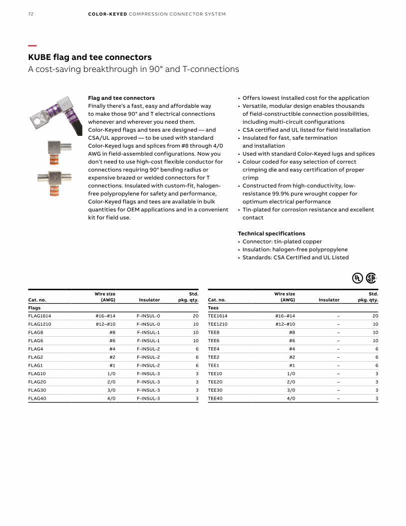
B1 copy starts here
B2 copy starts here
B3 copy starts here
72 CO LO R- K E Y E D CO M PR E SSI O N CO N N EC TO R S Y S TEM
—KUBE flag and tee connectorsA cost-saving breakthrough in 90° and T-connections
Flag and tee connectorsFinally there’s a fast, easy and affordable way to make those 90° and T electrical connections whenever and wherever you need them. Color-Keyed flags and tees are designed — and CSA/UL approved — to be used with standard Color-Keyed lugs and splices from #8 through 4/0 AWG in field-assembled configurations. Now you don’t need to use high-cost flexible conductor for connections requiring 90° bending radius or expensive brazed or welded connectors for T connections. Insulated with custom-fit, halogen-free polypropylene for safety and performance, Color-Keyed flags and tees are available in bulk quantities for OEM applications and in a convenient kit for field use.
• Offers lowest installed cost for the application• Versatile, modular design enables thousands
of field-constructible connection possibilities, including multi-circuit configurations
• CSA certified and UL listed for field installation• Insulated for fast, safe termination
and installation• Used with standard Color-Keyed lugs and splices• Colour coded for easy selection of correct
crimping die and easy certification of proper crimp
• Constructed from high-conductivity, low-resistance 99.9% pure wrought copper for optimum electrical performance
• Tin-plated for corrosion resistance and excellent contact
Technical specifications• Connector: tin-plated copper• Insulation: halogen-free polypropylene• Standards: CSA Certified and UL Listed
Cat. no.Wire size
(AWG) InsulatorStd.
pkg. qty.
Flags
FLAG1614 #16–#14 F-INSUL-0 20
FLAG1210 #12–#10 F-INSUL-0 10
FLAG8 #8 F-INSUL-1 10
FLAG6 #6 F-INSUL-1 10
FLAG4 #4 F-INSUL-2 6
FLAG2 #2 F-INSUL-2 6
FLAG1 #1 F-INSUL-2 6
FLAG10 1/0 F-INSUL-3 3
FLAG20 2/0 F-INSUL-3 3
FLAG30 3/0 F-INSUL-3 3
FLAG40 4/0 F-INSUL-3 3
Cat. no.Wire size
(AWG) InsulatorStd.
pkg. qty.
Tees
TEE1614 #16–#14 – 20
TEE1210 #12–#10 – 10
TEE8 #8 – 10
TEE6 #6 – 10
TEE4 #4 – 6
TEE2 #2 – 6
TEE1 #1 – 6
TEE10 1/0 – 3
TEE20 2/0 – 3
TEE30 3/0 – 3
TEE40 4/0 – 3
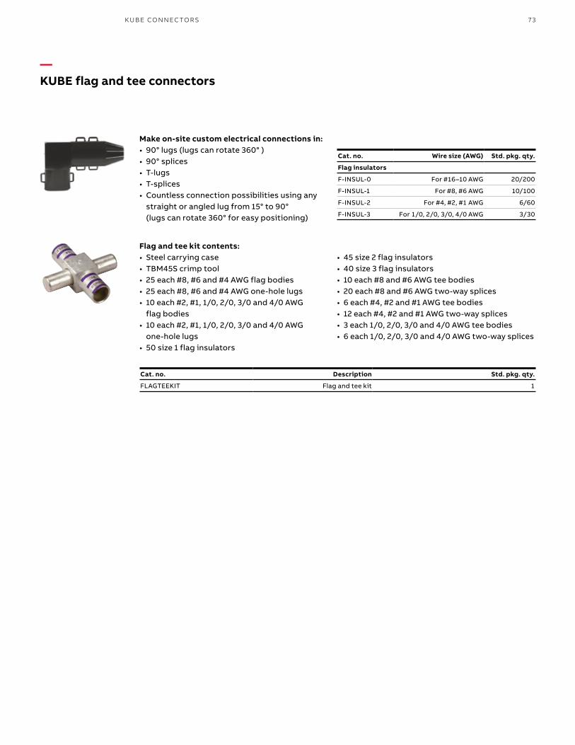
73KU B E CO N N EC TO R S
—KUBE flag and tee connectors
Make on-site custom electrical connections in:• 90° lugs (lugs can rotate 360° )• 90° splices• T-lugs• T-splices• Countless connection possibilities using any
straight or angled lug from 15° to 90° (lugs can rotate 360° for easy positioning)
Flag and tee kit contents:• Steel carrying case• TBM45S crimp tool• 25 each #8, #6 and #4 AWG flag bodies• 25 each #8, #6 and #4 AWG one-hole lugs• 10 each #2, #1, 1/0, 2/0, 3/0 and 4/0 AWG
flag bodies• 10 each #2, #1, 1/0, 2/0, 3/0 and 4/0 AWG
one-hole lugs• 50 size 1 flag insulators
Cat. no. Wire size (AWG) Std. pkg. qty.
Flag insulators
F-INSUL-0 For #16–10 AWG 20/200
F-INSUL-1 For #8, #6 AWG 10/100
F-INSUL-2 For #4, #2, #1 AWG 6/60
F-INSUL-3 For 1/0, 2/0, 3/0, 4/0 AWG 3/30
• 45 size 2 flag insulators• 40 size 3 flag insulators• 10 each #8 and #6 AWG tee bodies• 20 each #8 and #6 AWG two-way splices• 6 each #4, #2 and #1 AWG tee bodies• 12 each #4, #2 and #1 AWG two-way splices• 3 each 1/0, 2/0, 3/0 and 4/0 AWG tee bodies• 6 each 1/0, 2/0, 3/0 and 4/0 AWG two-way splices
Cat. no. Description Std. pkg. qty.
FLAGTEEKIT Flag and tee kit 1
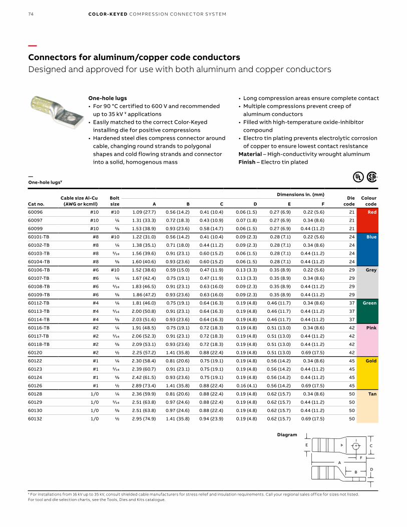
B1 copy starts here
B2 copy starts here
B3 copy starts here
74 CO LO R- K E Y E D CO M PR E SSI O N CO N N EC TO R S Y S TEM
—Connectors for aluminum/copper code conductorsDesigned and approved for use with both aluminum and copper conductors
• Long compression areas ensure complete contact• Multiple compressions prevent creep of
aluminum conductors• Filled with high-temperature oxide-inhibitor
compound• Electro tin plating prevents electrolytic corrosion
of copper to ensure lowest contact resistanceMaterial – High-conductivity wrought aluminum Finish – Electro tin plated
— One-hole lugs¥
One-hole lugs• For 90 °C certified to 600 V and recommended
up to 35 kV ¥ applications• Easily matched to the correct Color-Keyed
installing die for positive compressions• Hardened steel dies compress connector around
cable, changing round strands to polygonal shapes and cold flowing strands and connector into a solid, homogenous mass
Cat no.Cable size Al-Cu
(AWG or kcmil)Bolt size
Dimensions in. (mm)Die
codeColour
codeA B C D E F
60096 #10 #10 1.09 (27.7) 0.56 (14.2) 0.41 (10.4) 0.06 (1.5) 0.27 (6.9) 0.22 (5.6) 21 Red
60097 #10 1/4 1.31 (33.3) 0.72 (18.3) 0.43 (10.9) 0.07 (1.8) 0.27 (6.9) 0.34 (8.6) 21
60099 #10 3/8 1.53 (38.9) 0.93 (23.6) 0.58 (14.7) 0.06 (1.5) 0.27 (6.9) 0.44 (11.2) 21
60101-TB #8 #10 1.22 (31.0) 0.56 (14.2) 0.41 (10.4) 0.09 (2.3) 0.28 (7.1) 0.22 (5.6) 24 Blue
60102-TB #8 1/4 1.38 (35.1) 0.71 (18.0) 0.44 (11.2) 0.09 (2.3) 0.28 (7.1) 0.34 (8.6) 24
60103-TB #8 5⁄16 1.56 (39.6) 0.91 (23.1) 0.60 (15.2) 0.06 (1.5) 0.28 (7.1) 0.44 (11.2) 24
60104-TB #8 3/8 1.60 (40.6) 0.93 (23.6) 0.60 (15.2) 0.06 (1.5) 0.28 (7.1) 0.44 (11.2) 24
60106-TB #6 #10 1.52 (38.6) 0.59 (15.0) 0.47 (11.9) 0.13 (3.3) 0.35 (8.9) 0.22 (5.6) 29 Grey
60107-TB #6 1/4 1.67 (42.4) 0.75 (19.1) 0.47 (11.9) 0.13 (3.3) 0.35 (8.9) 0.34 (8.6) 29
60108-TB #6 5⁄16 1.83 (46.5) 0.91 (23.1) 0.63 (16.0) 0.09 (2.3) 0.35 (8.9) 0.44 (11.2) 29
60109-TB #6 3/8 1.86 (47.2) 0.93 (23.6) 0.63 (16.0) 0.09 (2.3) 0.35 (8.9) 0.44 (11.2) 29
60112-TB #4 1/4 1.81 (46.0) 0.75 (19.1) 0.64 (16.3) 0.19 (4.8) 0.46 (11.7) 0.34 (8.6) 37 Green
60113-TB #4 5⁄16 2.00 (50.8) 0.91 (23.1) 0.64 (16.3) 0.19 (4.8) 0.46 (11.7) 0.44 (11.2) 37
60114-TB #4 3/8 2.03 (51.6) 0.93 (23.6) 0.64 (16.3) 0.19 (4.8) 0.46 (11.7) 0.44 (11.2) 37
60116-TB #2 1/4 1.91 (48.5) 0.75 (19.1) 0.72 (18.3) 0.19 (4.8) 0.51 (13.0) 0.34 (8.6) 42 Pink
60117-TB #2 5⁄16 2.06 (52.3) 0.91 (23.1) 0.72 (18.3) 0.19 (4.8) 0.51 (13.0) 0.44 (11.2) 42
60118-TB #2 3/8 2.09 (53.1) 0.93 (23.6) 0.72 (18.3) 0.19 (4.8) 0.51 (13.0) 0.44 (11.2) 42
60120 #2 1/2 2.25 (57.2) 1.41 (35.8) 0.88 (22.4) 0.19 (4.8) 0.51 (13.0) 0.69 (17.5) 42
60122 #1 1/4 2.30 (58.4) 0.81 (20.6) 0.75 (19.1) 0.19 (4.8) 0.56 (14.2) 0.34 (8.6) 45 Gold
60123 #1 5⁄16 2.39 (60.7) 0.91 (23.1) 0.75 (19.1) 0.19 (4.8) 0.56 (14.2) 0.44 (11.2) 45
60124 #1 3/8 2.42 (61.5) 0.93 (23.6) 0.75 (19.1) 0.19 (4.8) 0.56 (14.2) 0.44 (11.2) 45
60126 #1 1/2 2.89 (73.4) 1.41 (35.8) 0.88 (22.4) 0.16 (4.1) 0.56 (14.2) 0.69 (17.5) 45
60128 1/0 1/4 2.36 (59.9) 0.81 (20.6) 0.88 (22.4) 0.19 (4.8) 0.62 (15.7) 0.34 (8.6) 50 Tan
60129 1/0 5⁄16 2.51 (63.8) 0.97 (24.6) 0.88 (22.4) 0.19 (4.8) 0.62 (15.7) 0.44 (11.2) 50
60130 1/0 3/8 2.51 (63.8) 0.97 (24.6) 0.88 (22.4) 0.19 (4.8) 0.62 (15.7) 0.44 (11.2) 50
60132 1/0 1/2 2.95 (74.9) 1.41 (35.8) 0.94 (23.9) 0.19 (4.8) 0.62 (15.7) 0.69 (17.5) 50
¥ For installations from 16 kV up to 35 kV, consult shielded cable manufacturers for stress relief and insulation requirements. Call your regional sales office for sizes not listed.For tool and die selection charts, see the Tools, Dies and Kits catalogue.
Diagram
E
D
C
A
B
F
E C
FA
BD

75CO N N EC TO R S FO R A LU M I N U M/CO PPER CO D E CO N D U C TO R S
—Connectors for aluminum/copper code conductorsDesigned and approved for use with both aluminum and copper conductors
Material – High-conductivity wrought aluminum Finish – Electro tin plated
— One-hole lugs¥ (continued)
Cat no.Cable size Al-Cu
(AWG or kcmil)Bolt size
Dimensions in. (mm)Die
codeColour
codeA B C D E F
60134 2/0 1/4 2.48 (63.0) 0.87 (22.1) 0.97 (24.6) 0.22 (5.6) 0.70 (17.8) 0.34 (8.6) 54 Olive
60135 2/0 5⁄16 2.64 (67.1) 1.03 (26.2) 0.97 (24.6) 0.22 (5.6) 0.70 (17.8) 0.44 (11.2) 54
60136 2/0 3/8 2.64 (67.1) 1.03 (26.2) 0.97 (24.6) 0.22 (5.6) 0.70 (17.8) 0.44 (11.2) 54
60138 2/0 1/2 3.10 (78.7) 1.41 (35.8) 1.03 (26.2) 0.22 (5.6) 0.70 (17.8) 0.69 (17.5) 54
60140 3/0 1/4 2.58 (65.5) 0.87 (22.1) 1.06 (26.9) 0.22 (5.6) 0.77 (19.6) 0.34 (8.6) 60 Ruby
60141 3/0 5⁄16 2.83 (71.9) 1.09 (27.7) 1.06 (26.9) 0.22 (5.6) 0.77 (19.6) 0.44 (11.2) 60
60142 3/0 3/8 2.83 (71.9) 1.09 (27.7) 1.06 (26.9) 0.22 (5.6) 0.77 (19.6) 0.44 (11.2) 60
60144 3/0 1/2 3.15 (80.0) 1.41 (35.8) 1.06 (26.9) 0.22 (5.6) 0.77 (19.6) 0.69 (17.5) 60
60147 4/0 5⁄16 3.53 (89.7) 0.88 (22.4) 1.21 (30.7) 0.25 (6.4) 0.86 (21.8) 0.38 (9.7) 66 White
60148 4/0 3/8 3.59 (91.2) 0.93 (23.6) 1.21 (30.7) 0.25 (6.4) 0.86 (21.8) 0.38 (9.7) 66
60150 4/0 1/2 3.90 (99.1) 1.25 (31.8) 1.21 (30.7) 0.25 (6.4) 0.86 (21.8) 0.50 (12.7) 66
60151 4/0 5/8 4.65 (118.1) 2.00 (50.8) 1.21 (30.7) 0.25 (6.4) 0.86 (21.8) 0.75 (19.0) 66
60154 250 3/8 3.73 (94.7) 0.93 (23.6) 1.29 (32.8) 0.27 (6.9) 0.92 (23.4) 0.38 (9.7) 71 Red
60156 250 1/2 4.05 (102.9) 1.25 (31.8) 1.29 (32.8) 0.27 (6.9) 0.92 (23.4) 0.50 (12.7) 71
60157 250 5/8 4.80 (121.9) 2.00 (50.8) 1.29 (32.8) 0.27 (6.9) 0.92 (23.4) 0.75 (19.0) 71
60159 300 5⁄16 3.75 (95.3) 0.88 (22.4) 1.39 (35.3) 0.28 (7.1) 0.99 (25.1) 0.38 (9.7) 76 Blue
60160 300 3/8 3.80 (96.5) 0.93 (23.6) 1.39 (35.3) 0.28 (7.1) 0.99 (25.1) 0.38 (9.7) 76
60162 300 1/2 4.13 (104.9) 1.25 (31.8) 1.39 (35.3) 0.28 (7.1) 0.99 (25.1) 0.50 (12.7) 76
60165 350 1/2 4.83 (122.7) 1.25 (31.8) 1.53 (38.9) 0.33 (8.4) 1.09 (27.7) 0.50 (12.7) 87 Brown
60166 350 5/8 5.58 (141.7) 2.00 (50.8) 1.53 (38.9) 0.33 (8.4) 1.09 (27.7) 0.75 (19.0) 87
60168 400 1/2 4.95 (125.7) 1.25 (31.8) 1.65 (41.9) 0.38 (9.7) 1.18 (30.0) 0.50 (12.7) 94 Green
60171 500 1/2 4.95 (125.7) 1.25 (31.8) 1.79 (45.5) 0.38 (9.7) 1.28 (32.5) 0.50 (12.7) 99 Pink
60172 500 5/8 5.70 (144.8) 2.00 (50.8) 1.79 (45.5) 0.38 (9.7) 1.28 (32.5) 0.75 (19.0) 99
60174 600 5/8 5.83 (148.1) 2.00 (50.8) 1.92 (48.8) 0.37 (9.4) 1.36 (34.5) 0.75 (19.0) 106 Black
60176 700 5/8 5.95 (151.1) 2.00 (50.8) 2.04 (51.8) 0.38 (9.7) 1.44 (36.6) 0.75 (19.0) 112 Purple
60178 750 5/8 6.03 (153.2) 2.00 (50.8) 2.13 (54.1) 0.40 (10.2) 1.50 (38.1) 0.75 (19.0) 115 Yellow
60184 1,000 5/8 6.78 (172.2) 2.00 (50.8) 2.50 (63.5) 0.50 (12.7) 1.77 (45.0) 0.75 (19.0) 140 –
¥ For installations from 16 kV up to 35 kV, consult shielded cable manufacturers for stress relief and insulation requirements. Call your regional sales office for sizes not listed.For tool and die selection charts, see the Tools, Dies and Kits catalogue.
Diagram
E
D
C
A
B
F
E C
FA
BD
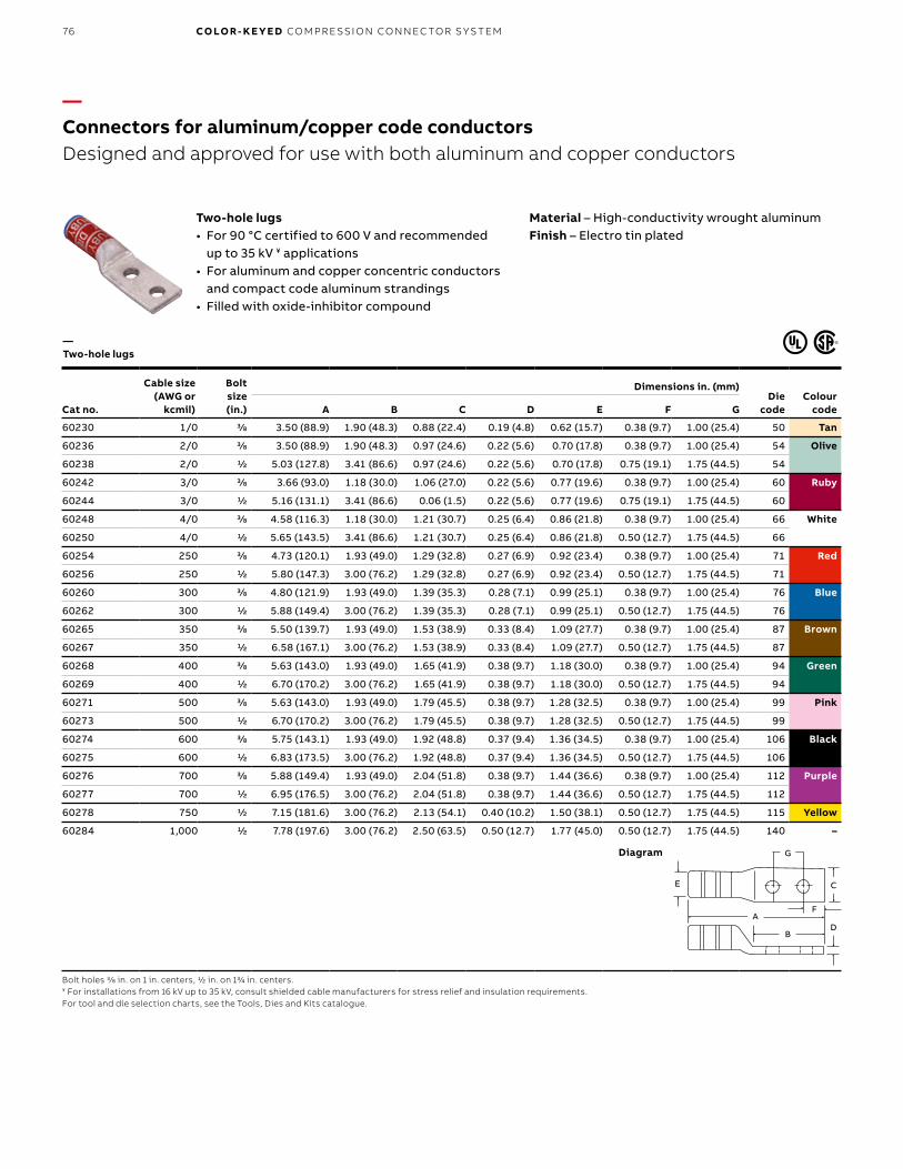
B1 copy starts here
B2 copy starts here
B3 copy starts here
76 CO LO R- K E Y E D CO M PR E SSI O N CO N N EC TO R S Y S TEM
—Connectors for aluminum/copper code conductorsDesigned and approved for use with both aluminum and copper conductors
Material – High-conductivity wrought aluminum Finish – Electro tin plated
— Two-hole lugs
Two-hole lugs• For 90 °C certified to 600 V and recommended
up to 35 kV ¥ applications• For aluminum and copper concentric conductors
and compact code aluminum strandings• Filled with oxide-inhibitor compound
Cat no.
Cable size (AWG or
kcmil)
Bolt size (in.)
Dimensions in. (mm)Die
codeColour
codeA B C D E F G
60230 1/0 3/8 3.50 (88.9) 1.90 (48.3) 0.88 (22.4) 0.19 (4.8) 0.62 (15.7) 0.38 (9.7) 1.00 (25.4) 50 Tan
60236 2/0 3/8 3.50 (88.9) 1.90 (48.3) 0.97 (24.6) 0.22 (5.6) 0.70 (17.8) 0.38 (9.7) 1.00 (25.4) 54 Olive
60238 2/0 1/2 5.03 (127.8) 3.41 (86.6) 0.97 (24.6) 0.22 (5.6) 0.70 (17.8) 0.75 (19.1) 1.75 (44.5) 54
60242 3/0 3/8 3.66 (93.0) 1.18 (30.0) 1.06 (27.0) 0.22 (5.6) 0.77 (19.6) 0.38 (9.7) 1.00 (25.4) 60 Ruby
60244 3/0 1/2 5.16 (131.1) 3.41 (86.6) 0.06 (1.5) 0.22 (5.6) 0.77 (19.6) 0.75 (19.1) 1.75 (44.5) 60
60248 4/0 3/8 4.58 (116.3) 1.18 (30.0) 1.21 (30.7) 0.25 (6.4) 0.86 (21.8) 0.38 (9.7) 1.00 (25.4) 66 White
60250 4/0 1/2 5.65 (143.5) 3.41 (86.6) 1.21 (30.7) 0.25 (6.4) 0.86 (21.8) 0.50 (12.7) 1.75 (44.5) 66
60254 250 3/8 4.73 (120.1) 1.93 (49.0) 1.29 (32.8) 0.27 (6.9) 0.92 (23.4) 0.38 (9.7) 1.00 (25.4) 71 Red
60256 250 1/2 5.80 (147.3) 3.00 (76.2) 1.29 (32.8) 0.27 (6.9) 0.92 (23.4) 0.50 (12.7) 1.75 (44.5) 71
60260 300 3/8 4.80 (121.9) 1.93 (49.0) 1.39 (35.3) 0.28 (7.1) 0.99 (25.1) 0.38 (9.7) 1.00 (25.4) 76 Blue
60262 300 1/2 5.88 (149.4) 3.00 (76.2) 1.39 (35.3) 0.28 (7.1) 0.99 (25.1) 0.50 (12.7) 1.75 (44.5) 76
60265 350 3/8 5.50 (139.7) 1.93 (49.0) 1.53 (38.9) 0.33 (8.4) 1.09 (27.7) 0.38 (9.7) 1.00 (25.4) 87 Brown
60267 350 1/2 6.58 (167.1) 3.00 (76.2) 1.53 (38.9) 0.33 (8.4) 1.09 (27.7) 0.50 (12.7) 1.75 (44.5) 87
60268 400 3/8 5.63 (143.0) 1.93 (49.0) 1.65 (41.9) 0.38 (9.7) 1.18 (30.0) 0.38 (9.7) 1.00 (25.4) 94 Green
60269 400 1/2 6.70 (170.2) 3.00 (76.2) 1.65 (41.9) 0.38 (9.7) 1.18 (30.0) 0.50 (12.7) 1.75 (44.5) 94
60271 500 3/8 5.63 (143.0) 1.93 (49.0) 1.79 (45.5) 0.38 (9.7) 1.28 (32.5) 0.38 (9.7) 1.00 (25.4) 99 Pink
60273 500 1/2 6.70 (170.2) 3.00 (76.2) 1.79 (45.5) 0.38 (9.7) 1.28 (32.5) 0.50 (12.7) 1.75 (44.5) 99
60274 600 3/8 5.75 (143.1) 1.93 (49.0) 1.92 (48.8) 0.37 (9.4) 1.36 (34.5) 0.38 (9.7) 1.00 (25.4) 106 Black
60275 600 1/2 6.83 (173.5) 3.00 (76.2) 1.92 (48.8) 0.37 (9.4) 1.36 (34.5) 0.50 (12.7) 1.75 (44.5) 106
60276 700 3/8 5.88 (149.4) 1.93 (49.0) 2.04 (51.8) 0.38 (9.7) 1.44 (36.6) 0.38 (9.7) 1.00 (25.4) 112 Purple
60277 700 1/2 6.95 (176.5) 3.00 (76.2) 2.04 (51.8) 0.38 (9.7) 1.44 (36.6) 0.50 (12.7) 1.75 (44.5) 112
60278 750 1/2 7.15 (181.6) 3.00 (76.2) 2.13 (54.1) 0.40 (10.2) 1.50 (38.1) 0.50 (12.7) 1.75 (44.5) 115 Yellow
60284 1,000 1/2 7.78 (197.6) 3.00 (76.2) 2.50 (63.5) 0.50 (12.7) 1.77 (45.0) 0.50 (12.7) 1.75 (44.5) 140 –
Bolt holes 3/8 in. on 1 in. centers, 1/2 in. on 13/4 in. centers.¥ For installations from 16 kV up to 35 kV, consult shielded cable manufacturers for stress relief and insulation requirements.For tool and die selection charts, see the Tools, Dies and Kits catalogue.
Diagram
E
D
C
A
B
F
G
E
A
BD
C
G
F

77CO N N EC TO R S FO R A LU M I N U M/CO PPER CO D E CO N D U C TO R S
—Connectors for aluminum/copper code conductors
Material – Aluminum Finish – Tin-plated
— Range-taking narrow-tongue single-barrel lugs
Range-taking narrow-tongue single-barrel lugs• For 90 °C certified to 600 V and recommended
up to 35 kV¥ applications• Bolt holes on 13/4 in. centers• Wire barrel factory-filled with oxide-inhibitor
compound
Cat no.Cable size
Al-Cu (kcmil)
Bolt size (in.)
No. of compression hydraulic 12 ton tool
or higher
Dimensions in. (mm) Hex die
codeColour
codeA B C D E
60273N 350–500 1/2 4 6.88 (174.8) 3.13 (79.5) 1.28 (32.5) 0.41 (10.4) 1.50 (38.1) 99H Pink
60278N 500–750 1/2 4 7.13 (181.1) 3.69 (93.7) 1.50 (38.1) 0.50 (12.7) 1.50 (38.1) 115H Yellow
60267NT 350 1/2 4 6.25 (158.75) 3.00 (76.2) 1.09 (27.68) 0.50 (12.7) 1.09 (27.68) 87H Brown
60273NT 500 1/2 3 5.06 (128.52) 3.00 (76.2) 1.18 (30.17) 0.50 (12.7) 1.18 (30.17) 94H Green
60275NT 600 1/2 3 5.38 (136.52) 3.00 (76.2) 1.30 (33.14) 0.50 (12.7) 1.30 (33.14) 99H Pink
60278NT 750 1/2 3 5.38 (136.52) 3.00 (76.2) 1.03 (26.16) 0.50 (12.7) 1.30 (33.14) 99H Pink
¥ For installations from 16 kV up to 35 kV, consult shielded cable manufacturers for stress relief and insulation requirements.For tool and die selection charts, see the Tools, Dies and Kits catalogue.
Diagram1-1/2
21/321-3/4
A
D
AB
Flat
5/16
C Dia.
D
B Flat
A
A
5⁄16"
C Dia.
13/4"
E
21/32"
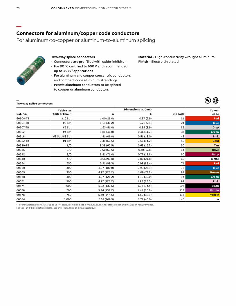
B1 copy starts here
B2 copy starts here
B3 copy starts here
78 CO LO R- K E Y E D CO M PR E SSI O N CO N N EC TO R S Y S TEM
—Connectors for aluminum/copper code conductorsFor aluminum-to-copper or aluminum-to-aluminum splicing
Material – High-conductivity wrought aluminum Finish – Electro tin plated
— Two-way splice connectors
Two-way splice connectors• Connectors are pre-filled with oxide-inhibitor• For 90 °C certified to 600 V and recommended
up to 35 kV¥ applications• For aluminum and copper concentric conductors
and compact code aluminum strandings• Permit aluminum conductors to be spliced
to copper or aluminum conductors
Cat. no.Cable size
(AWG or kcmil)
Dimensions in. (mm)
Die codeColour
codeA E
60500-TB #10 Str. 1.00 (25.4) 0.27 (6.9) 21 Red
60501-TB #8 Str. 1.19 (30.2) 0.28 (7.1) 24 Blue
60507-TB #6 Str. 1.63 (41.4) 0.35 (8.9) 29 Grey
60512 #4 Str. 1.81 (46.0) 0.46 (11.7) 37 Green
60516 #2 Str./#3 Str. 1.81 (46.0) 0.51 (13.0) 42 Pink
60522-TB #1 Str. 2.38 (60.5) 0.56 (14.2) 45 Gold
60530-TB 1/0 2.38 (60.5) 0.62 (15.7) 50 Tan
60536 2/0 2.50 (63.5) 0.70 (17.8) 54 Olive
60542 3/0 2.81 (71.4) 0.77 (19.6) 60 Ruby
60548 4/0 3.66 (93.0) 0.86 (21.8) 66 White
60554 250 3.91 (99.3) 0.92 (23.4) 71 Red
60560 300 3.97 (100.8) 0.99 (25.1) 76 Blue
60565 350 4.97 (126.2) 1.09 (27.7) 87 Brown
60568 400 4.97 (126.2) 1.18 (30.0) 94 Green
60571 500 4.97 (126.2) 1.28 (32.5) 99 Pink
60574 600 5.22 (132.6) 1.36 (34.5) 106 Black
60576 700 5.44 (138.2) 1.44 (36.6) 112 Purple
60578 750 5.69 (144.5) 1.50 (38.1) 115 Yellow
60584 1,000 6.69 (169.9) 1.77 (45.0) 140 –
¥ For installations from 16 kV up to 35 kV, consult shielded cable manufacturers for stress relief and insulation requirements.For tool and die selection charts, see the Tools, Dies and Kits catalogue.
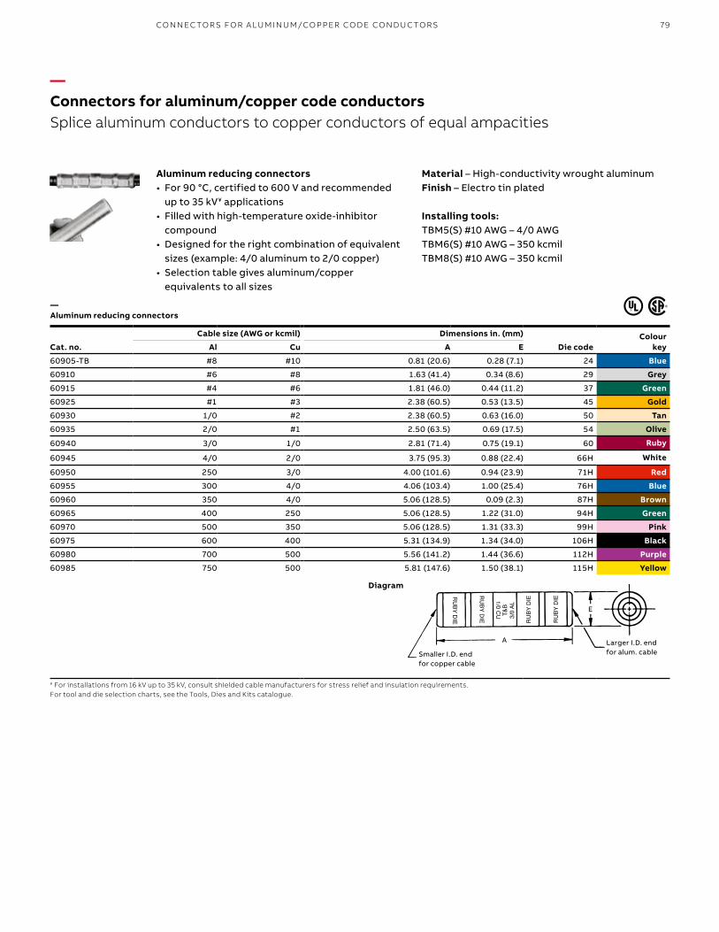
79
Cat. no.
Cable size (AWG or kcmil) Dimensions in. (mm)
Die code Colour
keyAl Cu A E
60905-TB #8 #10 0.81 (20.6) 0.28 (7.1) 24 Blue
60910 #6 #8 1.63 (41.4) 0.34 (8.6) 29 Grey
60915 #4 #6 1.81 (46.0) 0.44 (11.2) 37 Green
60925 #1 #3 2.38 (60.5) 0.53 (13.5) 45 Gold
60930 1/0 #2 2.38 (60.5) 0.63 (16.0) 50 Tan
60935 2/0 #1 2.50 (63.5) 0.69 (17.5) 54 Olive
60940 3/0 1/0 2.81 (71.4) 0.75 (19.1) 60 Ruby
60945 4/0 2/0 3.75 (95.3) 0.88 (22.4) 66H White
60950 250 3/0 4.00 (101.6) 0.94 (23.9) 71H Red
60955 300 4/0 4.06 (103.4) 1.00 (25.4) 76H Blue
60960 350 4/0 5.06 (128.5) 0.09 (2.3) 87H Brown
60965 400 250 5.06 (128.5) 1.22 (31.0) 94H Green
60970 500 350 5.06 (128.5) 1.31 (33.3) 99H Pink
60975 600 400 5.31 (134.9) 1.34 (34.0) 106H Black
60980 700 500 5.56 (141.2) 1.44 (36.6) 112H Purple
60985 750 500 5.81 (147.6) 1.50 (38.1) 115H Yellow
¥ For installations from 16 kV up to 35 kV, consult shielded cable manufacturers for stress relief and insulation requirements.For tool and die selection charts, see the Tools, Dies and Kits catalogue.
—Connectors for aluminum/copper code conductorsSplice aluminum conductors to copper conductors of equal ampacities
Material – High-conductivity wrought aluminum Finish – Electro tin plated
Installing tools:TBM5(S) #10 AWG – 4/0 AWGTBM6(S) #10 AWG – 350 kcmilTBM8(S) #10 AWG – 350 kcmil
— Aluminum reducing connectors
Aluminum reducing connectors• For 90 °C, certified to 600 V and recommended
up to 35 kV¥ applications• Filled with high-temperature oxide-inhibitor
compound• Designed for the right combination of equivalent
sizes (example: 4/0 aluminum to 2/0 copper)• Selection table gives aluminum/copper
equivalents to all sizes
Smaller I.D. end for Copper cable
Larger I.D. end for Alum. cable
RU
BY DIE
RU
BY DIE R
UBY
DIE
RU
BY D
IE
T&B
3/0
AL
1/0 CU
A
E
A
Smaller I.D. end for copper cable
Larger I.D. end for alum. cable
E
Diagram
CO N N EC TO R S FO R A LU M I N U M/CO PPER CO D E CO N D U C TO R S

B1 copy starts here
B2 copy starts here
B3 copy starts here
80 CO LO R- K E Y E D CO M PR E SSI O N CO N N EC TO R S Y S TEM
—Connectors for aluminum/copper code conductorsMuch smaller than standard aluminum lugs for the same cable size
One-hole aluminum compact-size equipment lugs• For 90°C, certified 600 V applications• For use with aluminum cables only• Can be directly substituted for equipment
mechanical lugs in most applications• Only 7 dies handle all 14 lug sizes• Factory-filled with joint compound• Electro tin plated• Supplied with Neoprene insulating covers
— One-hole aluminum compact-size equipment lugs
Cat. no.
Aluminum cable
(AWG or kcmil) size
Aluminum range
(AWG or kcmil) taking*
Bolt hole (in.)
Dimensions in. (mm)
A B C D E F
61102 #8 – 1⁄4 1.33 (33.8) 0.54 (13.7) 0.50 (12.7) 0.14 (3.6) 0.37 (9.4) 0.25 (6.4)
61107 #6 – 1⁄4 1.33 (33.8) 0.54 (13.7) 0.50 (12.7) 0.14 (3.6) 0.37 (9.4) 0.25 (6.4)
61112 #4 – 1⁄4 1.33 (33.8) 0.54 (13.7) 0.50 (12.7) 0.14 (3.6) 0.37 (9.4) 0.25 (6.4)
61116 #2 – 1⁄4 1.75 (44.5) 0.68 (17.3) 0.55 (14.0) 0.20 (5.1) 0.48 (12.2) 0.25 (6.4)
61122 #1 – 1⁄4 1.75 (44.5) 0.68 (17.3) 0.55 (14.0) 0.20 (5.1) 0.48 (12.2) 0.25 (6.4)
61130 1/0 #8–1/0 3⁄8 2.00 (50.8) 0.83 (21.1) 0.64 (16.3) 0.20 (5.1) 0.57 (14.5) 0.38 (9.7)
61136 2/0 #1–2/0 3⁄8 2.00 (50.8) 0.83 (21.1) 0.64 (16.3) 0.20 (5.1) 0.57 (14.5) 0.38 (9.7)
61142 3/0 – 3⁄8 2.50 (63.5) 1.08 (27.4) 0.78 (19.8) 0.23 (5.8) 0.70 (17.8) 0.38 (9.7)
61148 4/0 2/0–4/0 3⁄8 2.50 (63.5) 1.08 (27.4) 0.78 (19.8) 0.23 (5.8) 0.70 (17.8) 0.38 (9.7)
61156 250 – 1⁄2 2.50 (63.5) 1.23 (31.2) 0.98 (24.9) 0.25 (6.4) 0.85 (21.6) 0.50 (12.7)
61162 300 #4–300 1⁄2 2.50 (63.5) 1.23 (31.2) 0.98 (24.9) 0.25 (6.4) 0.85 (21.6) 0.50 (12.7)
61165 350 250–350 1⁄2 3.25 (82.6) 1.23 (31.2) 1.20 (30.5) 0.41 (10.4) 1.04 (26.4) 0.56 (14.2)
61171 500 2/0–500 1⁄2 3.25 (82.6) 1.23 (31.2) 1.20 (30.5) 0.41 (10.4) 1.04 (26.4) 0.56 (14.2)
61178 750 500–750 5⁄8 3.75 (95.3) 1.54 (39.1) 1.49 (37.8) 0.41 (10.4) 1.33 (33.8) 0.81 (20.6)
*For range-taking capability, use TBM8-750/TBM8-750M-1 Smart Tools.For tool and die selection charts, see the Tools, Dies and Kits catalogue.
B
D
E
A
F
C
Diagrams
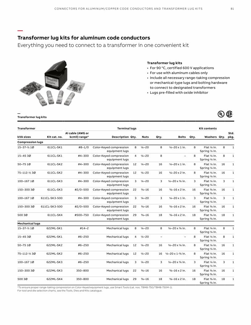
81CO N N EC TO R S FO R A LU M I N U M/CO PPER CO D E CO N D U C TO R S A N D TR A NSFO R M ER LU G K ITS
—Transformer lug kits for aluminum code conductorsEverything you need to connect to a transformer in one convenient kit
Transformer lug kits • For 90 °C, certified 600 V applications• For use with aluminum cables only• Include all necessary range-taking compression
or mechanical-type lugs and bolting hardware to connect to designated transformers
• Lugs pre-filled with oxide inhibitor
Transformer Kit contents
Qty.Std. pkg.
Terminal lugs
kVA sizes Kit cat. no.Al cable (AWG or
kcmil) range* Description Qty. Nuts Qty. Bolts Qty. Washers
Compression lugs
15–37-1⁄2 1Ø 611CL-SK1 #8–1/0 Color-Keyed compression equipment lugs
8 1/4–20 8 1/4–20 x 1 in. 8 Flat 1/4 in. Spring 1/4 in.
8 1
15–45 3Ø 611CL-SK1 #4–300 Color-Keyed compression equipment lugs
4 1/4–20 8 – 8 Flat 1/4 in. Spring 1/4 in.
8 1
50–75 1Ø 611CL-SK2 #4–300 Color-Keyed compression equipment lugs
12 1/4–20 16 1/4–20 x 1 in. 8 Flat 1/4 in. Spring 1/4 in.
16 1
75–112-1⁄2 3Ø 611CL-SK2 #4–300 Color-Keyed compression equipment lugs
12 1/4–20 16 1/4–20 x 2 in. 8 Flat 1/4 in. Spring 1/4 in.
16 1
100–167 1Ø 611CL-SK3 #4–300 Color-Keyed compression equipment lugs
3 1/4–20 3 1/4–20 x 3/4 in. 3 Flat 1/4 in. Spring 1/4 in.
3 1
150–300 3Ø 611CL-SK3 #2/0–500 Color-Keyed compression equipment lugs
22 3/8–16 16 3/8–16 x 2 in. 16 Flat 3/8 in. Spring 3/8 in.
16 1
100–167 1Ø 611CL-SK3-500 #4–300 Color-Keyed compression equipment lugs
3 1/4–20 3 1/4–20 x 1 in. 3 Flat 1/4 in. Spring 1/4 in.
3 1
150–300 3Ø 611CL-SK3-500 #2/0–500 Color-Keyed compression equipment lugs
22 3/8–16 16 3/8–16 x 2 in. 16 Flat 3/8 in. Spring 3/8 in.
16 1
500 3Ø 611CL-SK4 #500–750 Color-Keyed compression equipment lugs
29 3/8–16 18 3/8–16 x 2 in. 18 Flat 3/8 in. Spring 3/8 in.
18 1
Mechanical lugs
15–37-1⁄2 1Ø 622ML-SK1 #14–2 Mechanical lugs 8 1/4–20 8 1/4–20 x 3/4 in. 8 Flat 1/4 in. Spring 1/4 in.
8 1
15–45 3Ø 622ML-SK1 #6–250 Mechanical lugs 4 1/4–20 – – 8 Flat 1/4 in. Spring 1/4 in.
8 1
50–75 1Ø 622ML-SK2 #6–250 Mechanical lugs 12 1/4–20 16 1/4–20 x 1/4 in. 8 Flat 1/4 in. Spring 1/4 in.
16 1
75–112-1⁄2 3Ø 622ML-SK2 #6–250 Mechanical lugs 12 1/4–20 16 1/4–20 x 1-3/4 in. 8 Flat 1/4 in. Spring 1/4 in.
16 1
100–167 1Ø 622ML-SK3 #6–250 Mechanical lugs 3 1/4–20 3 1/4–20 x 3/4 in. 3 Flat 1/4 in. Spring 1/4 in.
3 1
150–300 3Ø 622ML-SK3 350–800 Mechanical lugs 22 3/8–16 16 3/8–16 x 2 in. 16 Flat 3/8 in. Spring 3/8 in.
16 1
500 3Ø 622ML-SK4 350–800 Mechanical lugs 29 3/8–16 18 3/8–16 x 2 in. 18 Flat 3/8 in. Spring 3/8 in.
18 1
*To ensure proper range-taking compression on Color-Keyed equipment lugs, use Smart Tools (cat. nos. TBM8-750/TBM8-750M-1).For tool and die selection charts, see the Tools, Dies and Kits catalogue.
—Transformer lug kits

B1 copy starts here
B2 copy starts here
B3 copy starts here
82 CO LO R- K E Y E D CO M PR E SSI O N CO N N EC TO R S Y S TEM
—Pin connectors for aluminum/copper code conductorsConverts an aluminum cable into a two-sizes-smaller copper pigtail
Bi-pin® bi-metal pin connectors • For 90 °C, 600 V applications• Upgrades connection by eliminating cold
flow and oxidation of aluminum• Reduces oversized aluminum cable• Enables termination of aluminum cable
into a copper-only lug• Barrel prefilled with joint compoundMaterial – Copper wire/aluminum bodyFinish – Electro tin platedInsulator – Neoprene (600 V dielectric rating)
Cat. no. insulating covers
Cat. no. heat shrink covers
Aluminum cable size
(AWG or kcmil)
Copper wire size
(AWG or kcmil)Body length after
installing (in.)Die code
no.Colour
code
61905A 61905AT #8 #10 1.88 24 Blue
61910A 61910AT #6 #8 1.88 24
61915A 61915AT #4 #6 1.56 45 Gold
61920A 61920AT #2 #4 1.56 45
61925A 61925AT #1 #3 1.63 50 Orange
61930A 61930AT 1/0 #2 1.63 50
61935 61935T 2/0 #1 1.94 50
61940 61940T 3/0 1/0 2.13 60 Ruby
61945 61945T 4/0 2/0 2.13 60
61950 61950T 250 3/0 2.19 66 White
61955 61955T 300 4/0 2.50 71H Red
61960 61960T 350 250 2.50 71H
61963 61963T 400 250 3.75 87H Brown
61965 61965T 500 350 3.75 87H
61970 61970T 600 400 3.75 107H Orange
61975 61975T 700–750 500 3.75 107H
Hand tools – Smart ToolsFor tool and die selection charts, see the Tools, Dies and Kits catalogue.
Strip Length
Aluminum Cable(For Termination)Stranded Copper Wire/Cable
(Factory Installed)
Length
ConnectorInstalled
Body LengthInstalled
To inspect installation:Match the installing dies to the pin connectorpermanent embossing. (For tools with code embossing dies)
Diameter of pinconnector assy.
Insulator
Connector installed with insulator
Strip Length
Aluminum Cable(For Termination)Stranded Copper Wire/Cable
(Factory Installed)
Length
Diameter of pin connector assy.
Insulator
Connector installed with insulator
Length
Stranded copper wire/cable (factory installed)
Strip length
Aluminum cable(for termination)
Connector installed
Body length installed
To inspect installation: Match the installing dies to the pin connector permanent embossing. (For tools with code embossing dies)
Diagrams
—Bi-pin bi-metal pin connectors
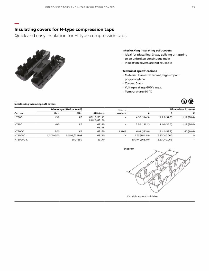
83PI N CO N N EC TO R S A N D H -TA P INSU L ATIN G COV ER S
Cat. no.
Wire range (AWG or kcmil)
Al H-tapsUse to
insulate
Dimensions in. (mm)
Max. Min. A B C
HT20C 2/0 #6 63110/63115 63125/63120
– 4.50 (114.3) 1.25 (31.8) 1.12 (28.4)
HT40C 4/0 #6 63140 63148
– 5.60 (142.2) 1.40 (35.6) 1.18 (30.0)
HT600C 500 #2 63160 63169 6.81 (173.0) 2.12 (53.8) 1.60 (40.6)
HT1000C 1,000–500 250–1/0 AWG 63180 – 7.25 (184.15) 2.330+0.066 –
HT1000C-L 250–250 63170 10.374 (263.40) 2.330+0.066 –
(C) Height – typical both halves
C
B
A
—Insulating covers for H-type compression tapsQuick and easy insulation for H-type compression taps
— Interlocking insulating soft covers
Interlocking insulating soft covers• Ideal for pigtailing, 2-way splicing or tapping
to an unbroken continuous main• Insulation covers are not reusable
Technical specifications• Material: Flame-retardant, high-impact
polypropylene• Colour: Black• Voltage rating: 600 V max.• Temperature: 90 °C
Diagram
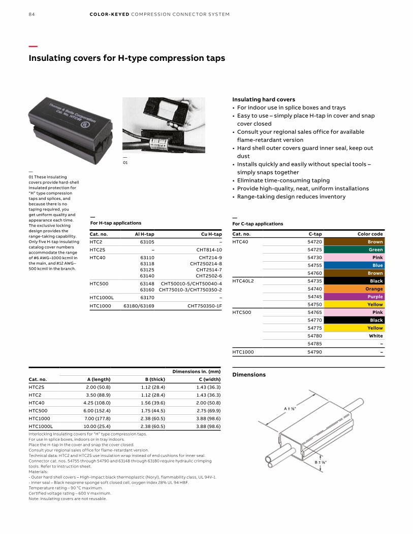
B1 copy starts here
B2 copy starts here
B3 copy starts here
84 CO LO R- K E Y E D CO M PR E SSI O N CO N N EC TO R S Y S TEM
—Insulating covers for H-type compression taps
Dimensions
—01 These insulating covers provide hard-shell insulated protection for “H” type compression taps and splices, and because there is no taping required, you get uniform quality and appearance each time. The exclusive locking design provides the range-taking capability. Only five H-tap insulating catalog cover numbers accommodate the range of #6 AWG–1000 kcmil in the main, and #12 AWG–500 kcmil in the branch.
—01
Insulating hard covers• For indoor use in splice boxes and trays• Easy to use – simply place H-tap in cover and snap
cover closed• Consult your regional sales office for available
flame-retardant version• Hard shell outer covers guard inner seal, keep out
dust• Installs quickly and easily without special tools –
simply snaps together• Eliminate time-consuming taping• Provide high-quality, neat, uniform installations• Range-taking design reduces inventory
Cat. no.
Dimensions in. (mm)
A (length) B (thick) C (width)
HTC2S 2.00 (50.8) 1.12 (28.4) 1.43 (36.3)
HTC2 3.50 (88.9) 1.12 (28.4) 1.43 (36.3)
HTC40 4.25 (108.0) 1.56 (39.6) 2.00 (50.8)
HTC500 6.00 (152.4) 1.75 (44.5) 2.75 (69.9)
HTC1000 7.00 (177.8) 2.38 (60.5) 3.88 (98.6)
HTC1000L 10.00 (25.4) 2.38 (60.5) 3.88 (98.6)
Interlocking insulating covers for “H” type compression taps. For use in splice boxes, indoors or in tray indoors. Place the H-tap in the cover and snap the cover closed. Consult your regional sales office for flame-retardant version.Technical data: HTC2 and HTC2S use insulation wrap instead of end cushions for inner seal.Connector cat. nos. 54755 through 54790 and 63148 through 63180 require hydraulic crimping tools. Refer to instruction sheet.Materials:- Outer hard shell covers – High-impact black thermoplastic (Noryl), flammability class, UL 94V-1. - Inner seal – Black neoprene sponge soft closed cell, oxygen index 28% UL 94 HBF.Temperature rating – 90 °C maximum. Certified voltage rating – 600 V maximum.Note: Insulating covers are not reusable.
Cat. no. Al H-tap Cu H-tap
HTC2 63105 –
HTC2S – CHT814-10
HTC40 63110 63118 63125 63140
CHT214-9 CHT250214-8
CHT2514-7 CHT2502-6
HTC500 63148 63160
CHT50010-5/CHT50040-4 CHT75010-3/CHT750350-2
HTC1000L 63170 –
HTC1000 63180/63169 CHT750350-1F
Cat. no. C-tap Color code
HTC40 54720 Brown
54725 Green
54730 Pink
54755 Blue
54760 Brown
HTC40L2 54735 Black
54740 Orange
54745 Purple
54750 Yellow
HTC500 54765 Pink
54770 Black
54775 Yellow
54780 White
54785 –
HTC1000 54790 –
B ± 1⁄8"
A ± 1⁄8"
—For H-tap applications
—For C-tap applications
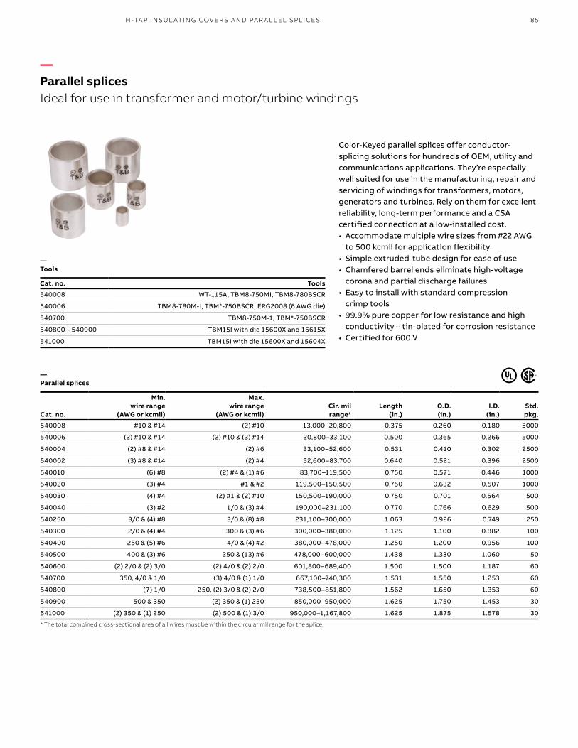
85H -TA P I NSU L ATI N G COV ER S A N D PA R A L L EL SPL I CE S
—Parallel splicesIdeal for use in transformer and motor/turbine windings
Color-Keyed parallel splices offer conductor-splicing solutions for hundreds of OEM, utility and communications applications. They’re especially well suited for use in the manufacturing, repair and servicing of windings for transformers, motors, generators and turbines. Rely on them for excellent reliability, long-term performance and a CSA certified connection at a low-installed cost. • Accommodate multiple wire sizes from #22 AWG
to 500 kcmil for application flexibility• Simple extruded-tube design for ease of use• Chamfered barrel ends eliminate high-voltage
corona and partial discharge failures• Easy to install with standard compression
crimp tools • 99.9% pure copper for low resistance and high
conductivity – tin-plated for corrosion resistance• Certified for 600 V
— Parallel splices
Cat. no.
Min. wire range
(AWG or kcmil)
Max. wire range
(AWG or kcmil)Cir. milrange*
Length (in.)
O.D. (in.)
I.D. (in.)
Std. pkg.
540008 #10 & #14 (2) #10 13,000–20,800 0.375 0.260 0.180 5000
540006 (2) #10 & #14 (2) #10 & (3) #14 20,800–33,100 0.500 0.365 0.266 5000
540004 (2) #8 & #14 (2) #6 33,100–52,600 0.531 0.410 0.302 2500
540002 (3) #8 & #14 (2) #4 52,600–83,700 0.640 0.521 0.396 2500
540010 (6) #8 (2) #4 & (1) #6 83,700–119,500 0.750 0.571 0.446 1000
540020 (3) #4 #1 & #2 119,500–150,500 0.750 0.632 0.507 1000
540030 (4) #4 (2) #1 & (2) #10 150,500–190,000 0.750 0.701 0.564 500
540040 (3) #2 1/0 & (3) #4 190,000–231,100 0.770 0.766 0.629 500
540250 3/0 & (4) #8 3/0 & (8) #8 231,100–300,000 1.063 0.926 0.749 250
540300 2/0 & (4) #4 300 & (3) #6 300,000–380,000 1.125 1.100 0.882 100
540400 250 & (5) #6 4/0 & (4) #2 380,000–478,000 1.250 1.200 0.956 100
540500 400 & (3) #6 250 & (13) #6 478,000–600,000 1.438 1.330 1.060 50
540600 (2) 2/0 & (2) 3/0 (2) 4/0 & (2) 2/0 601,800–689,400 1.500 1.500 1.187 60
540700 350, 4/0 & 1/0 (3) 4/0 & (1) 1/0 667,100–740,300 1.531 1.550 1.253 60
540800 (7) 1/0 250, (2) 3/0 & (2) 2/0 738,500–851,800 1.562 1.650 1.353 60
540900 500 & 350 (2) 350 & (1) 250 850,000–950,000 1.625 1.750 1.453 30
541000 (2) 350 & (1) 250 (2) 500 & (1) 3/0 950,000–1,167,800 1.625 1.875 1.578 30
* The total combined cross-sectional area of all wires must be within the circular mil range for the splice.
— Tools
Cat. no. Tools
540008 WT-115A, TBM8-750MI, TBM8-780BSCR
540006 TBM8-780M-I, TBM*-750BSCR, ERG2008 (6 AWG die)
540700 TBM8-750M-1, TBM*-750BSCR
540800 – 540900 TBM15I with die 15600X and 15615X
541000 TBM15I with die 15600X and 15604X
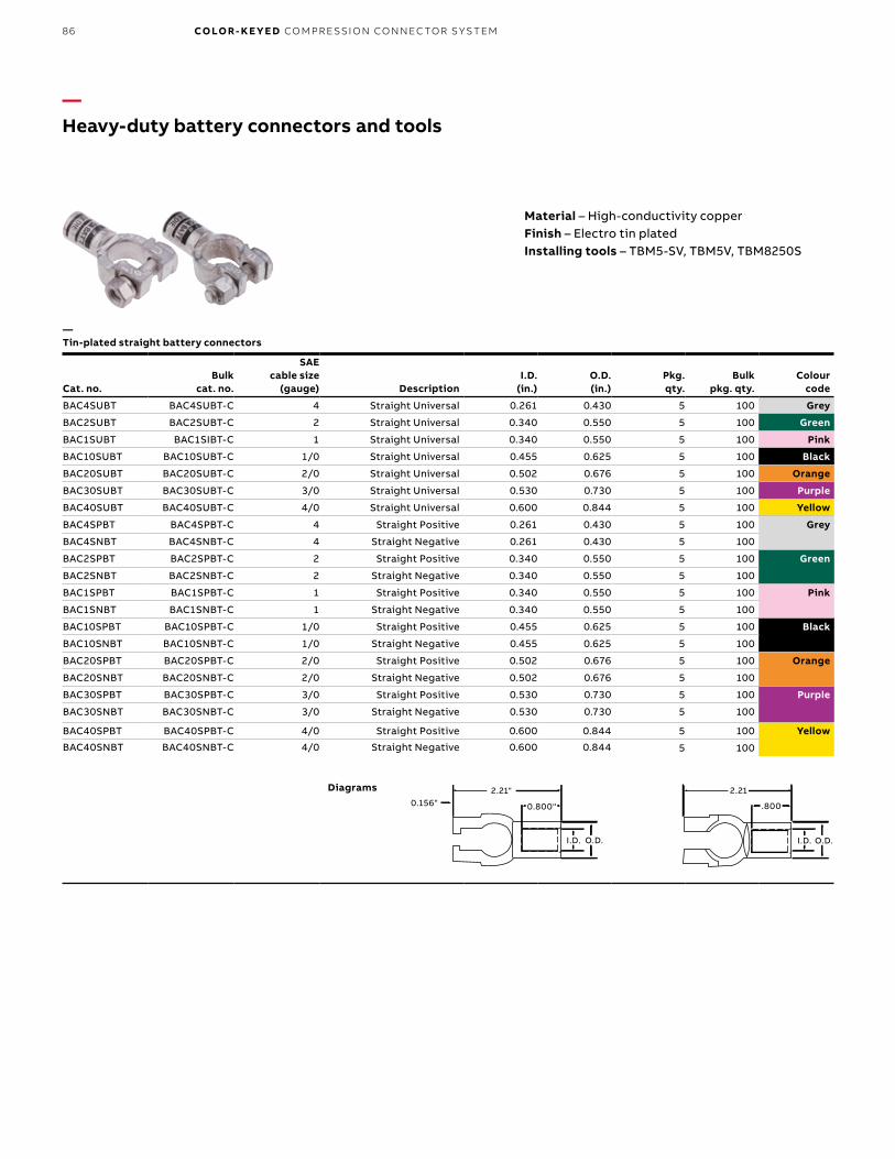
B1 copy starts here
B2 copy starts here
B3 copy starts here
86 CO LO R- K E Y E D CO M PR E SSI O N CO N N EC TO R S Y S TEM
Material – High-conductivity copperFinish – Electro tin platedInstalling tools – TBM5-SV, TBM5V, TBM8250S
—Heavy-duty battery connectors and tools
Cat. no.Bulk
cat. no.
SAE cable size
(gauge) DescriptionI.D.
(in.)O.D. (in.)
Pkg. qty.
Bulkpkg. qty.
Colour code
BAC4SUBT BAC4SUBT-C 4 Straight Universal 0.261 0.430 5 100 Grey
BAC2SUBT BAC2SUBT-C 2 Straight Universal 0.340 0.550 5 100 Green
BAC1SUBT BAC1SIBT-C 1 Straight Universal 0.340 0.550 5 100 Pink
BAC10SUBT BAC10SUBT-C 1/0 Straight Universal 0.455 0.625 5 100 Black
BAC20SUBT BAC20SUBT-C 2/0 Straight Universal 0.502 0.676 5 100 Orange
BAC30SUBT BAC30SUBT-C 3/0 Straight Universal 0.530 0.730 5 100 Purple
BAC40SUBT BAC40SUBT-C 4/0 Straight Universal 0.600 0.844 5 100 Yellow
BAC4SPBT BAC4SPBT-C 4 Straight Positive 0.261 0.430 5 100 Grey
BAC4SNBT BAC4SNBT-C 4 Straight Negative 0.261 0.430 5 100
BAC2SPBT BAC2SPBT-C 2 Straight Positive 0.340 0.550 5 100 Green
BAC2SNBT BAC2SNBT-C 2 Straight Negative 0.340 0.550 5 100
BAC1SPBT BAC1SPBT-C 1 Straight Positive 0.340 0.550 5 100 Pink
BAC1SNBT BAC1SNBT-C 1 Straight Negative 0.340 0.550 5 100
BAC10SPBT BAC10SPBT-C 1/0 Straight Positive 0.455 0.625 5 100 Black
BAC10SNBT BAC10SNBT-C 1/0 Straight Negative 0.455 0.625 5 100
BAC20SPBT BAC20SPBT-C 2/0 Straight Positive 0.502 0.676 5 100 Orange
BAC20SNBT BAC20SNBT-C 2/0 Straight Negative 0.502 0.676 5 100
BAC30SPBT BAC30SPBT-C 3/0 Straight Positive 0.530 0.730 5 100 Purple
BAC30SNBT BAC30SNBT-C 3/0 Straight Negative 0.530 0.730 5 100
BAC40SPBT BAC40SPBT-C 4/0 Straight Positive 0.600 0.844 5 100 Yellow
BAC40SNBT BAC40SNBT-C 4/0 Straight Negative 0.600 0.844 5 100
2.21"0.156" 0.800"
I.D. O.D.
2.21
.800
I.D. O.D.
Diagrams
—Tin-plated straight battery connectors
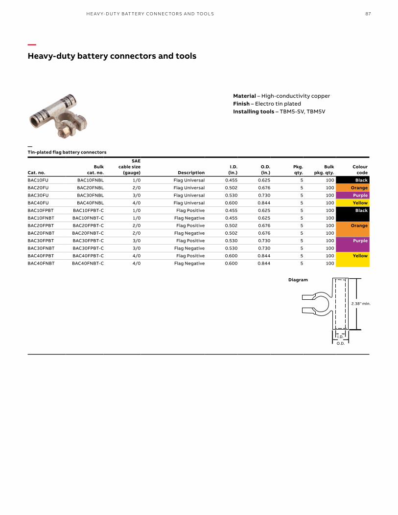
87H E AV Y- D U T Y B AT TER Y CO N N EC TO R S A N D TO O L S
Material – High-conductivity copperFinish – Electro tin platedInstalling tools – TBM5-SV, TBM5V
Cat. no.Bulk
cat. no.
SAE cable size
(gauge) DescriptionI.D.
(in.)O.D. (in.)
Pkg. qty.
Bulk pkg. qty.
Colour code
BAC10FU BAC10FNBL 1/0 Flag Universal 0.455 0.625 5 100 Black
BAC20FU BAC20FNBL 2/0 Flag Universal 0.502 0.676 5 100 Orange
BAC30FU BAC30FNBL 3/0 Flag Universal 0.530 0.730 5 100 Purple
BAC40FU BAC40FNBL 4/0 Flag Universal 0.600 0.844 5 100 Yellow
BAC10FPBT BAC10FPBT-C 1/0 Flag Positive 0.455 0.625 5 100 Black
BAC10FNBT BAC10FNBT-C 1/0 Flag Negative 0.455 0.625 5 100
BAC20FPBT BAC20FPBT-C 2/0 Flag Positive 0.502 0.676 5 100 Orange
BAC20FNBT BAC20FNBT-C 2/0 Flag Negative 0.502 0.676 5 100
BAC30FPBT BAC30FPBT-C 3/0 Flag Positive 0.530 0.730 5 100 Purple
BAC30FNBT BAC30FPBT-C 3/0 Flag Negative 0.530 0.730 5 100
BAC40FPBT BAC40FPBT-C 4/0 Flag Positive 0.600 0.844 5 100 Yellow
BAC40FNBT BAC40FNBT-C 4/0 Flag Negative 0.600 0.844 5 100
2.38 Min
I.D.O.D.I.D.
O.D.
2.38" min.
—Heavy-duty battery connectors and tools
Diagram
—Tin-plated flag battery connectors

B1 copy starts here
B2 copy starts here
B3 copy starts here
88 CO LO R- K E Y E D CO M PR E SSI O N CO N N EC TO R S Y S TEM
Cat. no.Bulk
cat. no.
SAE cable size
(gauge) DescriptionI.D.
(in.)O.D. (in.)
Pkg.qty.
Bulkpkg. qty.
Colour code
BAC10ERNBT BAC10ERNBT-C 1/0 Right Elbow–Negative 0.455 0.625 5 100 Black
BAC10ERPBT BAC10ERPBT-C 1/0 Right Elbow–Positive 0.455 0.625 5 100
BAC20ERNBT BAC20ERNBT-C 2/0 Right Elbow–Negative 0.502 0.676 5 100 Orange
BAC20ERPBT BAC20ERPBT-C 2/0 Right Elbow–Positive 0.502 0.676 5 100
BAC30ERNBT BAC30ERNBT-C 3/0 Right Elbow–Negative 0.530 0.730 5 100 Purple
BAC30ERPBT BAC30ERPBT-C 3/0 Right Elbow–Positive 0.530 0.730 5 100
BAC40ERNBT BAC40ERNBT-C 4/0 Right Elbow–Negative 0.600 0.844 5 100 Yellow
BAC40ERPBT BAC40ERPBT-C 4/0 Right Elbow–Positive 0.600 0.844 5 100
BAC10ELNBT BAC10ELNBT-C 1/0 Left Elbow–Negative 0.455 0.625 5 100 Black
BAC10ELPBT BAC10ELPBT-C 1/0 Left Elbow–Positive 0.455 0.625 5 100
BAC20ELNBT BAC20ELNBT-C 2/0 Left Elbow–Negative 0.502 0.676 5 100 Orange
BAC20ELPBT BAC20ELPBT-C 2/0 Left Elbow–Positive 0.502 0.676 5 100
BAC30ELNBT BAC30ELNBT-C 3/0 Left Elbow–Negative 0.530 0.730 5 100 Purple
BAC30ELPBT BAC30ELPBT-C 3/0 Left Elbow–Positive 0.530 0.730 5 100
BAC40ELNBT BAC40ELNBT-C 4/0 Left Elbow–Negative 0.600 0.844 5 100 Yellow
BAC40ELPBT BAC40ELPBT-C 4/0 Left Elbow–Positive 0.600 0.844 5 100
Material – High-conductivity copperFinish – Electro tin platedInstalling tools – TBM5-SV, TBM5V
I.D.
O.D.
1.81" - Negative1.84" - Positive
—Heavy-duty battery connectors and tools
Diagram
—Tin-plated elbow battery connectors

89H E AV Y- D U T Y B AT TER Y CO N N EC TO R S A N D TO O L S
Material – High-conductivity copperFinish – Lead-platedInstalling tools – TBM5-SV or TBM5V
Cat. no.Bulk
cat. no.
SAE cable size
(gauge)
Dimensions in. (mm) Stud size (in.)
Pkg.qty.
Bulk pkg. qty.
Colourcode
A ±0.040
M ±0.020
W ±0.020
C ±0.020
E ±0.010
BAC438 273-31853-1 4 1.46 (37.0) 1.14 (29.0) 0.62 (15.6) 0.75 (19.1) 0.37 (9.3) 3⁄8 10 100 Grey
BAC238 273-31853-2 2 1.78 (45.1) 1.40 (35.6) 0.68 (17.1) 0.85 (21.6) 0.47 (11.9) 3⁄8 10 100 Green
BAC138 273-31853-3 1 1.88 (47.6) 1.50 (38.1) 0.75 (44.5) 0.95 (24.1 0.52 (13.2) 3⁄8 10 100 Pink
BAC1038 273-31853-4 1/0 1.93 (48.9) 1.55 (39.4) 0.83 (21.0) 1.00 (25.4) 0.57 (14.5) 3⁄8 10 100 Black
BAC2038 273-31853-5 2/0 2.11 (53.6) 1.65 (41.8) 0.93 (23.6) 1.10 (27.9) 0.63 (16.1) 3⁄8 10 100 Orange
BAC3038 273-31853-6 3/0 2.03 (51.4) 1.65 (41.9) 1.03 (26.0) 1.10 (27.9) 0.70 (17.8) 3⁄8 10 100 Purple
BAC4038 273-31853-7 4/0 2.23 (57.8) 1.90 (48.3) 1.03 (26.0) 1.35 (34.3) 0.77 (19.5) 3⁄8 10 100 Yellow
ORAN
GE
2/0
BATT
ORAN
GE
2/0
BATT
D
C MAX
A MAX
W MAX
M MAX E MAX
For 3⁄8" threaded stud maintenance-free batteries
M max
W max
C max
E max
A max
DAnti-rotation pads
Color code
—Heavy-duty battery connectors and tools
Diagram
—Stackable battery connectors – Lead-plated

B1 copy starts here
B2 copy starts here
B3 copy starts here
90 CO LO R- K E Y E D CO M PR E SSI O N CO N N EC TO R S Y S TEM
Cat. no.Bulk
cat. no.
SAE cable size
(gauge)
Stud size (in.)
Dimensions (mm)
Pkg. qty.
Bulk pkg. qty.
Colour code
A ±0.04
B ±0.02
C ±0.02
D ±0.02
BAL414 273-31852-1 4 1⁄4 140 52 40 115 10 100 Grey
BAL4516 273-31852-2 4 5⁄16 145 61 363 114 10 100
BAL438 273-31852-3 4 3⁄8 145 61 6 114 10 100
BAL2516 – 2 5⁄16 159 69 40 1258 10 – Green
BAL238 273-31852-4 2 3⁄8 178 67 55 140 10 100
BAL212 273-31852-5 2 1⁄2 177 76 54 140 10 100
BAL1516 – 1 5⁄16 183 76 49 150 10 – Pink
BAL138 273-31852-6 1 3⁄8 185 75 55 150 10 100
BAL112 273-31852-7 1 1⁄2 220 75 75 170 10 100
BAL10516 – 1/0 5⁄16 192 83 50 150 10 – Black
BAL1038 273-31852-8 1/0 3⁄8 193 83 55 155 10 100
BAL1012 273-31852-9 1/0 1⁄2 197 88 53 153 10 100
BAL20516 – 2/0 5⁄16 206 93 50 160 10 – Orange
BAL2038 273-31852-10 2/0 3⁄8 211 93 55 165 10 100
BAL2012 273-31852-11 2/0 1⁄2 211 93 55 165 10 100
BAL30516 – 3/0 5⁄16 216 103 55 165 10 – Purple
BAL3038 273-31852-12 3/0 3⁄8 203 103 55 165 10 100
BAL3012 273-31852-13 3/0 1⁄2 235 103 75 185 10 100
BAL40516 – 4/0 5⁄16 240 113 59 184 10 – Yellow
BAL4038 273-31852-14 4/0 3⁄8 228 112 55 190 10 100
BAL4012 273-31852-15 4/0 1⁄2 260 112 75 210 10 100
—Heavy-duty battery connectors and tools
Material – High-conductivity copperFinish – Electro tin platedInstalling tools – TBM5-SV or TBM5V
ORANGE
2/0 BATT
2/0 BATT
T&
B
A
D
C
B
Diagram
—Starter lugs – Tin-plated

91H E AV Y- D U T Y B AT TER Y CO N N EC TO R S A N D TO O L S
Cat. no. Bulk cat. no.
SAE cable size
(gauge) Pkg. qty.Bulk
pkg. qty.Colour
code
BAS4 273-31852-16 4 10 100 Grey
BAS2 273-31852-17 2 10 100 Green
BAS1 273-31852-18 1 10 100 Pink
BAS10 273-31852-19 1/0 10 100 Black
BAS20 273-31852-20 2/0 10 100 Orange
BAS30 273-31852-21 3/0 10 100 Purple
BAS40 273-31852-22 4/0 10 100 Yellow
Material – High-conductivity copperFinish – Electro tin platedInstalling tools – TBM5-SV or TBM5V
—“Y” splices
Cat. no. Strip cable size
SAE cable size
(gauge) Length (in.)Colour
code
BASY20 2/0–(2) #2 2/0 3⁄4 Orange
BASY30 3/0–(2) #1 3/0 3⁄4 Purple
BASY40 4/0–(2) 1/0 4/0 3⁄4 Yellow
Material – High-conductivity copperFinish – Electro tin platedInstalling tools – TBM5-SV or TBM5VInsulating cover – AC5X3
—Splices (two-way connectors)
—Heavy-duty battery connectors and tools

B1 copy starts here
B2 copy starts here
B3 copy starts here
92 CO LO R- K E Y E D CO M PR E SSI O N CO N N EC TO R S Y S TEM
Battery/starter cables • Fine flexible copper rope stranding PVC jacket
conforms to SAE J1127 specifications• Layer of paper separates insulation from copper,
providing easy stripping with no stranding damage
• Temperature-rated for 80 °C• Flexibility ideal for tight spaces
and cold environments• Color-Keyed markings for fast
and accurate identification• Marked in 1-ft. increments for easy measurement• Available in red or black jacket colour
Cat. no.
SAE cable size
(gauge)Cable
length (ft.) Cable
colour
BC4-100 4 100 Black
BC2-100 2 100
BC1-100 1 100
BC10-100 1/0 100
BC20-100 2/0 100
BC30-100 3/0 100
BC40-100 4/0 100
BC4-1000 4 1,000
BC2-500 2 500
BC1-500 1 500
BC10-500 1/0 500
BC20-500 2/0 500
BC30-500 3/0 500
BC40-500 4/0 500
BC4-1000R 4 1,000 Red
BC2-500R 2 500
BC1-500R 1 500
BC10-500R 1/0 500
BC20-500R 2/0 500
BC30-500R 3/0 500
BC40-500R 4/0 500
Cat. no.
SAE cable size
(gauge)Cable
length (ft.) Cable
colour
BC4-25 4 25 Black
BC2-25 2 25
BC1-25 1 25
BC10-25 1/0 25
BC20-25 2/0 25
BC30-25 3/0 25
BC40-25 4/0 25
BC4-25R 4 25 Red
BC2-25R 2 25
BC1-25R 1 25
BC10-25R 1/0 25
BC20-25R 2/0 25
BC30-25R 3/0 25
BC40-25R 4/0 25
—Heavy-duty battery connectors and toolsAbrasion-resistant and engineered for optimum performance at both high and low temperatures
—Battery/starter cables
• 105 °C Temperature-rated and UL recognized• Heavier PVC jacket conforms to SAE J1127
specifications• Color-Keyed markings for fast
and accurate identification• Marked in 1-ft. increments for easy measurement
• Layer of paper separates insulation from copper for easy stripping with no strand damage
• 600 V rated available in bulk only• Application-specific – To order, contact your
regional sales offices
Material – High-conductivity copperFinish – Electro tin platedInstalling tools – TBM5-SV or TBM5V
—Heavy-duty battery cableSpecially designed for demanding industrial and OEM requirements
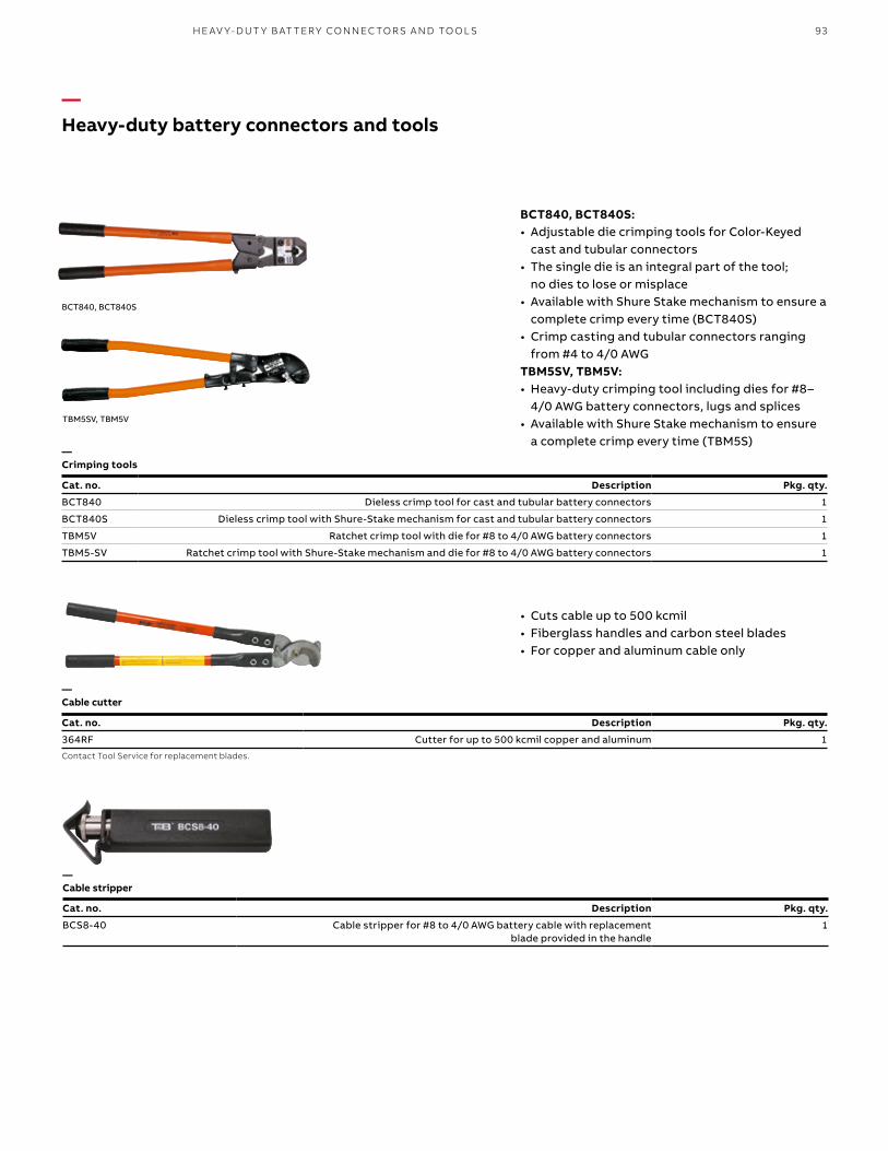
93H E AV Y- D U T Y B AT TER Y CO N N EC TO R S A N D TO O L S
—Heavy-duty battery connectors and tools
TBM5SV, TBM5V
Cat. no. Description Pkg. qty.
BCT840 Dieless crimp tool for cast and tubular battery connectors 1
BCT840S Dieless crimp tool with Shure-Stake mechanism for cast and tubular battery connectors 1
TBM5V Ratchet crimp tool with die for #8 to 4/0 AWG battery connectors 1
TBM5-SV Ratchet crimp tool with Shure-Stake mechanism and die for #8 to 4/0 AWG battery connectors 1
BCT840, BCT840S: • Adjustable die crimping tools for Color-Keyed
cast and tubular connectors• The single die is an integral part of the tool;
no dies to lose or misplace• Available with Shure Stake mechanism to ensure a
complete crimp every time (BCT840S)• Crimp casting and tubular connectors ranging
from #4 to 4/0 AWGTBM5SV, TBM5V:• Heavy-duty crimping tool including dies for #8–
4/0 AWG battery connectors, lugs and splices• Available with Shure Stake mechanism to ensure
a complete crimp every time (TBM5S)
BCT840, BCT840S
—Crimping tools
—Cable cutter
Cat. no. Description Pkg. qty.
364RF Cutter for up to 500 kcmil copper and aluminum 1
Contact Tool Service for replacement blades.
Cat. no. Description Pkg. qty.
BCS8-40 Cable stripper for #8 to 4/0 AWG battery cable with replacement blade provided in the handle
1
—Cable stripper
• Cuts cable up to 500 kcmil• Fiberglass handles and carbon steel blades• For copper and aluminum cable only
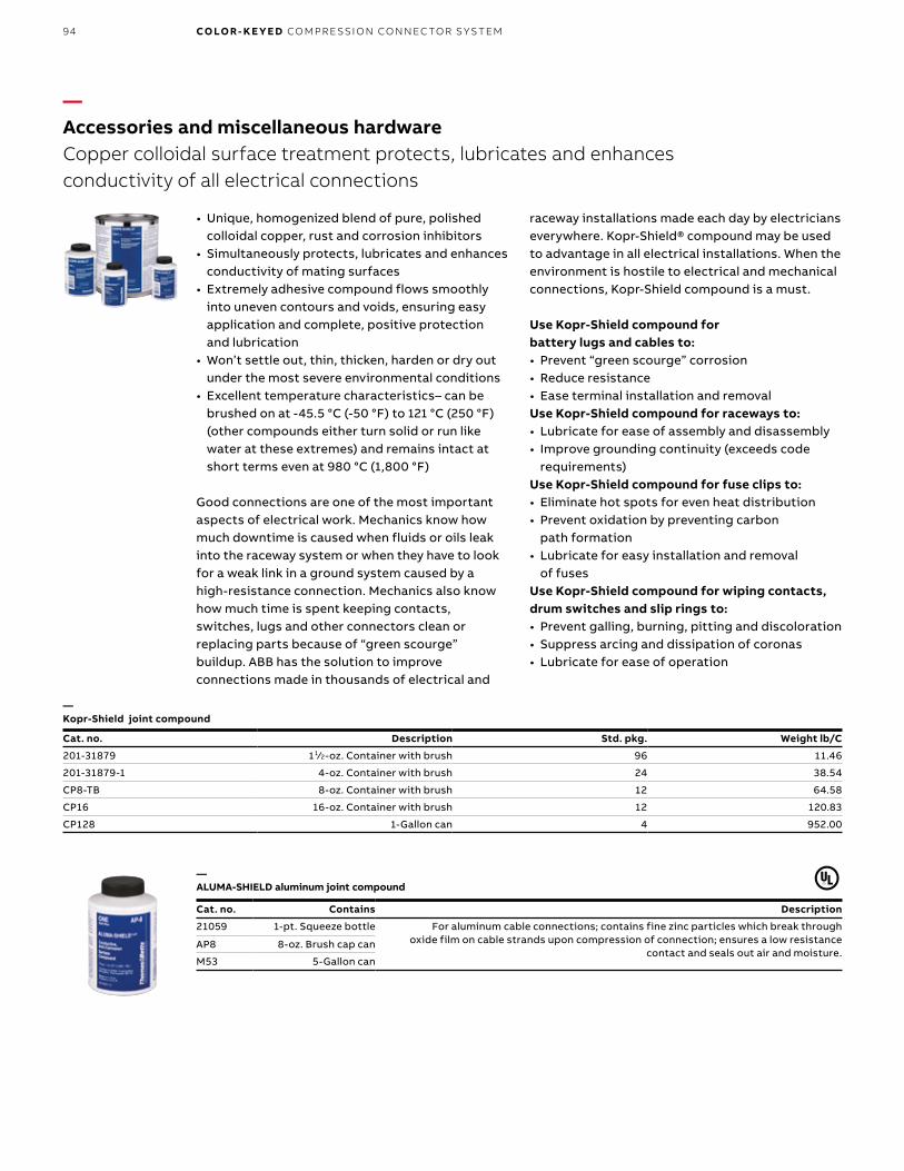
B1 copy starts here
B2 copy starts here
B3 copy starts here
94 CO LO R- K E Y E D CO M PR E SSI O N CO N N EC TO R S Y S TEM
Cat. no. Description Std. pkg. Weight lb/C
201-31879 11⁄2-oz. Container with brush 96 11.46
201-31879-1 4-oz. Container with brush 24 38.54
CP8-TB 8-oz. Container with brush 12 64.58
CP16 16-oz. Container with brush 12 120.83
CP128 1-Gallon can 4 952.00
• Unique, homogenized blend of pure, polished colloidal copper, rust and corrosion inhibitors
• Simultaneously protects, lubricates and enhances conductivity of mating surfaces
• Extremely adhesive compound flows smoothly into uneven contours and voids, ensuring easy application and complete, positive protection and lubrication
• Won’t settle out, thin, thicken, harden or dry out under the most severe environmental conditions
• Excellent temperature characteristics– can be brushed on at -45.5 °C (-50 °F) to 121 °C (250 °F) (other compounds either turn solid or run like water at these extremes) and remains intact at short terms even at 980 °C (1,800 °F)
Good connections are one of the most important aspects of electrical work. Mechanics know how much downtime is caused when fluids or oils leak into the raceway system or when they have to look for a weak link in a ground system caused by a high-resistance connection. Mechanics also know how much time is spent keeping contacts, switches, lugs and other connectors clean or replacing parts because of “green scourge” buildup. ABB has the solution to improve connections made in thousands of electrical and
raceway installations made each day by electricians everywhere. Kopr-Shield® compound may be used to advantage in all electrical installations. When the environment is hostile to electrical and mechanical connections, Kopr-Shield compound is a must.
Use Kopr-Shield compound for battery lugs and cables to:• Prevent “green scourge” corrosion• Reduce resistance• Ease terminal installation and removalUse Kopr-Shield compound for raceways to:• Lubricate for ease of assembly and disassembly• Improve grounding continuity (exceeds code
requirements)Use Kopr-Shield compound for fuse clips to:• Eliminate hot spots for even heat distribution• Prevent oxidation by preventing carbon
path formation• Lubricate for easy installation and removal
of fusesUse Kopr-Shield compound for wiping contacts, drum switches and slip rings to:• Prevent galling, burning, pitting and discoloration• Suppress arcing and dissipation of coronas• Lubricate for ease of operation
—Accessories and miscellaneous hardwareCopper colloidal surface treatment protects, lubricates and enhances conductivity of all electrical connections
—Kopr-Shield joint compound
— ALUMA-SHIELD aluminum joint compound
Cat. no. Contains Description
21059 1-pt. Squeeze bottle For aluminum cable connections; contains fine zinc particles which break through oxide film on cable strands upon compression of connection; ensures a low resistance
contact and seals out air and moisture.AP8 8-oz. Brush cap can
M53 5-Gallon can
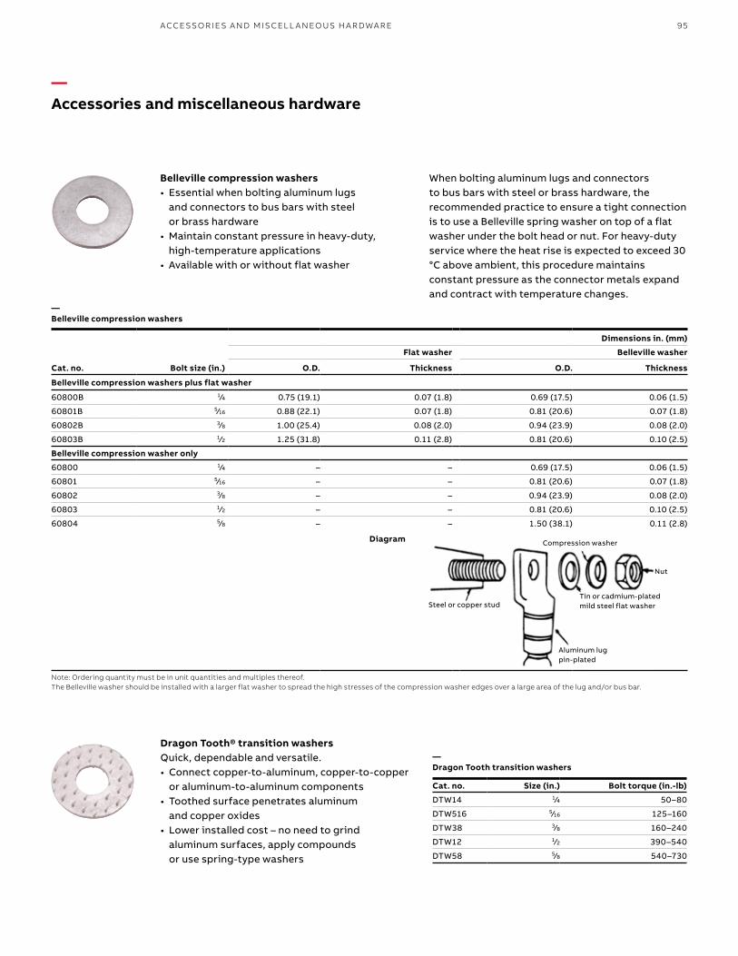
95ACCE SSO R IE S A N D M ISCEL L A N EO US H A R DWA R E
—Accessories and miscellaneous hardware
Belleville compression washers• Essential when bolting aluminum lugs
and connectors to bus bars with steel or brass hardware
• Maintain constant pressure in heavy-duty, high-temperature applications
• Available with or without flat washer
When bolting aluminum lugs and connectors to bus bars with steel or brass hardware, the recommended practice to ensure a tight connection is to use a Belleville spring washer on top of a flat washer under the bolt head or nut. For heavy-duty service where the heat rise is expected to exceed 30 °C above ambient, this procedure maintains constant pressure as the connector metals expand and contract with temperature changes.
Cat. no. Bolt size (in.)
Dimensions in. (mm)
Flat washer Belleville washer
O.D. Thickness O.D. Thickness
Belleville compression washers plus flat washer
60800B 1⁄4 0.75 (19.1) 0.07 (1.8) 0.69 (17.5) 0.06 (1.5)
60801B 5⁄16 0.88 (22.1) 0.07 (1.8) 0.81 (20.6) 0.07 (1.8)
60802B 3⁄8 1.00 (25.4) 0.08 (2.0) 0.94 (23.9) 0.08 (2.0)
60803B 1⁄2 1.25 (31.8) 0.11 (2.8) 0.81 (20.6) 0.10 (2.5)
Belleville compression washer only
60800 1⁄4 – – 0.69 (17.5) 0.06 (1.5)
60801 5⁄16 – – 0.81 (20.6) 0.07 (1.8)
60802 3⁄8 – – 0.94 (23.9) 0.08 (2.0)
60803 1⁄2 – – 0.81 (20.6) 0.10 (2.5)
60804 5⁄8 – – 1.50 (38.1) 0.11 (2.8)
Note: Ordering quantity must be in unit quantities and multiples thereof. The Belleville washer should be installed with a larger flat washer to spread the high stresses of the compression washer edges over a large area of the lug and/or bus bar.
Steel or copper stud
Compression washer
Nut
Tin or cadmium-plated mild steel flat washer
Aluminum lugpin-plated
Diagram
—Belleville compression washers
Cat. no. Size (in.) Bolt torque (in.-lb)
DTW14 1⁄4 50–80
DTW516 5⁄16 125–160
DTW38 3⁄8 160–240
DTW12 1⁄2 390–540
DTW58 5⁄8 540–730
Dragon Tooth® transition washersQuick, dependable and versatile. • Connect copper-to-aluminum, copper-to-copper
or aluminum-to-aluminum components• Toothed surface penetrates aluminum
and copper oxides• Lower installed cost – no need to grind
aluminum surfaces, apply compounds or use spring-type washers
—Dragon Tooth transition washers

B1 copy starts here
B2 copy starts here
B3 copy starts here
96 CO LO R- K E Y E D CO M PR E SSI O N CO N N EC TO R S Y S TEM
—Accessories and miscellaneous hardware
Cat. no.Diameter and threads per inch Length
(in.)1/4 in.–20 5/16 in.–18 3/8 in.–16 1/2 in.–13
Type BB — Silicon bronze hex head bolts
25100BB-C 31100BB-C 37100BB-C 50100BB-C 1
– 31125BB-C 37125BB-C 50125BB-C 11/4
– 31150BB-C 37150BB-C 50150BB-C 11/2
– 31175BB-C 37175BB-C 50175BB-C 13/4
– 32100BB-C 37200BB-C 50200BB-C 2
25225BB-C 31225BB-C 37225BB-C 50225BB-C 21/4
– 31250BB-C 37250BB-C 50250BB-C 21/2
– 31275BB-C 37275BB-C 50275BB-C 23/4
– 31300BB-C 37300BB-C 50300BB-C 3
– – 37325BB-C 50325BB-C 31/4
– – 37350BB-C 50350BB-C 31/2
Type HN — Silicon bronze hex nuts
14010HN-C 31010HN-C 37010HN-C 50010HN-C –
Cat. No. Bolt size (in.) O.D. (in.) I.D. (in.) Thickness (in.) Height (in.)
Type SW — Silicon bronze split lock washers
14030SW-C 1/4 – – – –
31030SW-C 5⁄16 – – – –
37030SW-C 3/8 – – – –
50030SW-C 1/2 – – – –
Type FW — Silicon bronze flat washers
14040FW-C 1/4 1/4 11⁄16 0.260 0.040
31040FW-C 5⁄16 5⁄16 7/8 0.336 0.064
37040FW-C 3/8 3/8 1 0.395 0.064
50040FW-C 1/2 1/2 11/4 0.562 0.091
Type BW – Belleville compression washer 304 series stainless steel
50050BW-C 1/2 11/8 17⁄32 0.062 1/8
— Hex head bolts and nuts
— Washers
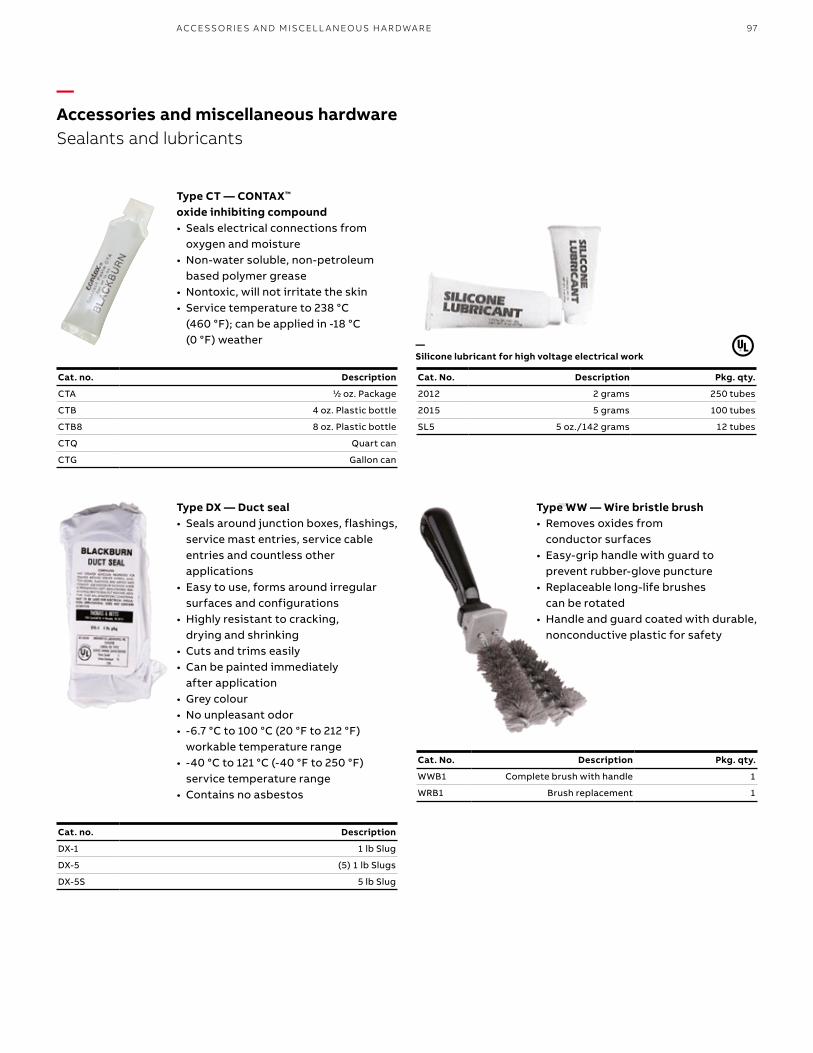
97ACCE SSO R IE S A N D M ISCEL L A N EO US H A R DWA R E
—Accessories and miscellaneous hardwareSealants and lubricants
Cat. no. Description
CTA 1⁄2 oz. Package
CTB 4 oz. Plastic bottle
CTB8 8 oz. Plastic bottle
CTQ Quart can
CTG Gallon can
Cat. No. Description Pkg. qty.
2012 2 grams 250 tubes
2015 5 grams 100 tubes
SL5 5 oz./142 grams 12 tubes
Type CT — CONTAX™ oxide inhibiting compound• Seals electrical connections from
oxygen and moisture• Non-water soluble, non-petroleum
based polymer grease• Nontoxic, will not irritate the skin• Service temperature to 238 °C
(460 °F); can be applied in -18 °C (0 °F) weather —
Silicone lubricant for high voltage electrical work
Type DX — Duct seal• Seals around junction boxes, flashings,
service mast entries, service cable entries and countless other applications
• Easy to use, forms around irregular surfaces and configurations
• Highly resistant to cracking, drying and shrinking
• Cuts and trims easily• Can be painted immediately
after application• Grey colour• No unpleasant odor• -6.7 °C to 100 °C (20 °F to 212 °F)
workable temperature range • -40 °C to 121 °C (-40 °F to 250 °F)
service temperature range• Contains no asbestos
Cat. no. Description
DX-1 1 lb Slug
DX-5 (5) 1 lb Slugs
DX-5S 5 lb Slug
Type WW — Wire bristle brush• Removes oxides from
conductor surfaces• Easy-grip handle with guard to
prevent rubber-glove puncture• Replaceable long-life brushes
can be rotated • Handle and guard coated with durable,
nonconductive plastic for safety
Cat. No. Description Pkg. qty.
WWB1 Complete brush with handle 1
WRB1 Brush replacement 1


