

TECHNICALDATA BOOK
As the leading provider of comprehensive emergency response and resolution, prevention, and operational services for the oil and gas industry, Wild Well offers innovative solutions to complex issues. No other company on earth can claim a more experienced team, more jobs successfully completed, or more industry personnel trained each year.
When it’s under Wild Well. Consider it covered.
EMERGENCY: 1.281.784.4700
Wild WellWorld Headquarters
1.281.784.4700 wildwell.com
A SUPERIOR ENERGY SERVICES COMPANY

Well Control Services Firefighting and well controlPressure controlHot tap and valve drillFreeze services
Well Control EngineeringWell modelingDynamic kill modelingRelief well planningWell control advisory and project management
Advanced EngineeringFlow assurance and thermal engineeringMultiphase flow and computational fluid dynamicsMulti-physics simulationsMechanical and structural design Advanced structural analysis 3D laser scanning and survey
Marine Well ServicesRiserless light well interventionUnconventional decommissioningWellCONTAINED™
Training & Rigsite ServicesWell control trainingRigsite assessment through kick drills Well control equipment surveysWell specific readiness training
HSE TrainingIncident response trainingIncident management training
CSI TechnologiesCement engineering servicesLab and testing servicesResin technologyResearch and product development

A Quick Reference Book of Formulas, Charts and Tables
A SUPERIOR ENERGY SERVICES COMPANY
© 2014 Wild Well Control, Inc.
The information contained herein has been collected from various sources. Accordingly, Wild Well Control, Inc. cannot and does not guarantee, warrant or represent the accuracy of or accept any responsibility for the use of any information contained herein.

2 Table of Contents
Acronyms & Abbreviations .................................................................................. 2
Common Formulas & Equations Capacities & Volumes for Downhole ............................................................... 4
Capacities & Volumes of Tanks ........................................................................ 5
Pump Output & Rate Formulas ......................................................................... 6
Pump Pressure Relationships ............................................................................ 6
Equivalent Circulating Density ......................................................................... 7
Trip Calculations ............................................................................................... 7
Pressure & Gradient Formulas .......................................................................... 8
Kick Related Formulas & Equations Kill Sheet Calculations ...................................................................................... 9
Kick Related Formulas .................................................................................... 10
Kick Related Engineering Calculations .......................................................... 11
Volumetric Method Calculations .................................................................... 12
Lubricate & Bleed Calculations ...................................................................... 12
Bullheading Calculations ................................................................................ 13
Stripping / Snubbing Calculations ................................................................... 14
Subsea Formulas ............................................................................................. 15
Accumulator Sizing ......................................................................................... 15
Mud & Cement Formulas ................................................................................ 16
Hydraulics Formulas ....................................................................................... 18
Estimates & Rules of Thumb Tripping ........................................................................................................... 18
Stuck Pipe ........................................................................................................ 19
Free Point and Stretch Estimates ..................................................................... 20
Temperature Drop Across Choke or Orifice ................................................... 21
Bit Nozzle Pressure Loss ................................................................................. 21
Gas Well Flow Rates ....................................................................................... 22
Area of a Circle ............................................................................................... 22
Force and Pressure .......................................................................................... 23
Weight of Spiral Drill Collars ......................................................................... 23
Buoyancy Factor ............................................................................................. 23
Surface and Bottom Hole Pressures in Full Gas Column ............................... 23
Pipe Elongation Due to Temperature .............................................................. 24
Pipe, BOP & Other Data Tables Drillpipe – Range II ......................................................................................... 26
Drillpipe Capacity & Displacement ................................................................ 27
Heavy-Weight Drillpipe .................................................................................. 28
Drill Collars ..................................................................................................... 29
Drill Collar Capacity & Displacement ............................................................ 31
KILL SHEET ................................................................................................. 32 API Tubing ...................................................................................................... 34
Premium Connection Tubing .......................................................................... 40
Casing Strength ............................................................................................... 42
Casing Capacity ............................................................................................... 45
Hole Capacity .................................................................................................. 47
Triplex Pumps at 100% Efficiency ................................................................. 48
Mud Weight Adjustments ............................................................................... 50
Mud Weights ................................................................................................... 51
Specifications for BOP Flanges, etc. .............................................................. 53
Gate Valve Data .............................................................................................. 54
API Ring Joint Flanges ................................................................................... 56
BOP Fluid Operating Volumes ....................................................................... 59
Coiled Tubing Data ......................................................................................... 65
Coiled Tubing Dimensions .............................................................................. 66
Electric Line .................................................................................................... 68
Wireline Data .................................................................................................. 70
Conversion Factors .......................................................................................... 71
Acronyms & Abbreviations 3
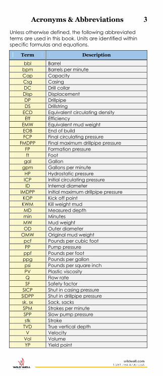
Unless otherwise defined, the following abbreviated terms are used in this book. Units are identified within specific formulas and equations.
Term Description
bbl Barrel bpm Barrels per minute Cap Capacity Csg Casing DC Drill collar Disp Displacement DP Drillpipe DS Drillstring
ECD Equivalent circulating density Eff Efficiency
EMW Equivalent mud weight EOB End of build FCP Final circulating pressure
FMDPP Final maximum drillpipe pressure FP Formation pressure ft Foot
gal Gallon gpm Gallons per minute HP Hydrostatic pressure ICP Initial circulating pressure ID Internal diameter
IMDPP Initial maximum drillpipe pressure KOP Kick off point KWM Kill weight mud MD Measured depth min Minutes MW Mud weight OD Outer diameter
OMW Original mud weight pcf Pounds per cubic foot PP Pump pressure ppf Pounds per foot ppg Pounds per gallon psi Pounds per square inch PV Plastic viscosity Q Flow rate SF Safety factor
SICP Shut in casing pressure SIDPP Shut in drillpipe pressure sk, sx Sack, sacks SPM Strokes per minute SPP Slow pump pressure stk Stroke
TVD True vertical depth V Velocity
Vol Volume YP Yield point

4 Formulas & Equations
CCaappaacciittiieess && VVoolluummeess ffoorr DDoowwnnhhoollee
Capacities
Open Hole Capacitybbl/ft (OHCap) =
1,029.4 )Diameter (Hole 2inches
Casing Capacitybbl/ft (CsgCap) = 1,029.4
)ID (Casing 2inches
Drill String Capacitybbl/ft (DSCap) = 1,029.4
)ID (Pipe 2inches
OH x DS Annular Capacitybbl/ft (OH x DSCap) =
4.029,1)ODString()erHoleDiamet( 22 inchesinches
Csg x DS Annular Capacitybbl/ft (Csg x DSCap) =
4.029,1)ODString()ID gsinCa( 22 inchesinches
Multiple String Annular Capacitybbl/ft (MSACap) =
4.029,1
)2ODPipe()1PipeOD()ID gsinCa( 222 inchesinchesinches
Volumes per Section
Open Hole Volumebbl (OHVol) = OHCapbbl/ft x Lengthft
Casing Volumebbl (CsgVol) = CsgCapbbl/ft x Lengthft
Drill String Volumebbl (DSVol) = DSCapbbl/ft x Lengthft
OH x DS Annular Volumebbl (OH x DSVol) = (OH x DSCap)bbl/ft x Lengthft
Csg x DS Annular Volumebbl (Csg x DSVol) = (Casg x DSCap)bbl/ft x Lengthft
Multiple String Annular Volumebbl (MSAVol) = MSACapbbl/ft x Lengthft

Formulas & Equations 5
CCaappaacciittiieess && VVoolluummeess ooff TTaannkkss
Vertical Cylindrical Tanks
Capacitybbl/ft = 7.148
Diameter Tank 2ft
Capacitybbl/ft = 1,029.4
Diameter Tank 2inches
Capacitybbl/inch = 85.78
Diameter Tank 2ft
Capacitybbl/inch = 12,352.9
Diameter Tank 2inches
Volumebbl = Capacitybbl/ft x Heightft Volumebbl = Capacitybbl/inch x Heightinches
Rectangular Tanks
Capacitybbl/ft = 0.178 x Lengthft x Widthft Capacitybbl/inch = 0.0148 x Lengthft x Widthft
Volumebbl = Capacitybbl/ft x Heightft Volumebbl = Capacitybbl/inch x Heightinches
Horizontal Cylindrical Tanks
Volume of Tankbbl = 1,029.4
Diameter TankLength2inches
ft
Content from Volume (for Horizontal Tanks)
Height Ratio = inches
inches
Tank of HeightContent of Height
FIND VOLUME FACTOR FROM TABLE USING CALCULATED HEIGHT RATIO:
Content in Tankbbl = Vol of Tankbbl x Volume Factor Height Ratio
Volume Factor
Height Ratio
Volume Factor
0.05 0.019 0.55 0.560 0.10 0.052 0.60 0.626 0.15 0.092 0.65 0.690 0.20 0.142 0.70 0.747 0.25 0.195 0.75 0.800 0.30 0.252 0.80 0.857 0.35 0.310 0.85 0.900 0.40 0.373 0.90 0.948 0.45 0.430 0.95 0.980 0.50 0.500 1.00 1.000

6 Formulas & Equations
PPuummpp OOuuttppuutt && RRaattee FFoorrmmuullaass
Pump Outputs
FOR TRIPLEX PUMPS:
Outputbbl/stk = 0.000243 x (Liner IDinches)2 x Strokeinches x Eff%
FOR DUPLEX PUMPS (DOUBLE ACTING):
Outputbbl/stk = 0.000162 x [2 x (Liner IDinches)2 – (Rod ODinches)2]
x Strokeinches x Eff%
Pump Rates
Ratebpm = Outputbbl/stk x SPM
Rategpm = 42 x Outputbbl/stk x SPM
Pumping/Spotting/Displacing
Timemin = SPMOutput
Pump to BBLbbl/stk
PPuummpp PPrreessssuurree RReellaattiioonnsshhiippss
New Pump Pressure (PP) for Rate Change
New PPpsi = psibpm
bpm PP Old Rate OldRate New 2
New PPpsi = psiPP Old SPM OldSPM New 2
New Pump Pressure (PP) for Density Change
New PPpsi = psippg
ppg PP Original MW Original
MW New

Formulas & Equations 7
EEqquuiivvaalleenntt CCiirrccuullaattiinngg DDeennssiittyy ((EECCDD))
Equivalent Circulating Density (ECDppg) using Pressure Loss
ECDppg = TVDft
psippg
Depth0.052
Loss Pressure Friction AnnularMW
Where: Annular Friction Pressure Loss in psi is approximately
equal to 10% of the pump pressure for normal hole geometries (i.e., no liners or tapered strings).
Equivalent Circulating Density (ECDppg) using Yield Point (YP) for MW 13 ppg
ECDppg = inchesinches
ppg
PipeOD - erHoleDiamet
YP0.1MW
Where: YP = Fann 300 reading – PV PV = Fann 600 reading – Fann 300 reading
Equivalent Circulating Density (ECDppg) using Yield Point (YP) for MW > 13 ppg
ECDppg = inchesinches
ppgPipeODerHoleDiamet
0.1MW
inchesinches
ft/min
PipeODerHoleDiamet300VPVYP
TTrriipp CCaallccuullaattiioonnss
Trip Marginppg
Trip Marginppg = inchesinches
mud
OD Pipe - Diameter Hole11.7YP
Trip Marginppg = TVDft
psi
Depth0.052Loss Pressure Annular
Slug Mud Weightppg for a given Length of Dry Pipe
Slug Weightppg =
bbl
bbl/ftftppgppg
Slug of VolumeCap DP Pipe Dry LengthMW MW
Slug Volumebbl for a given Length of Dry Pipe
Slug Volumebbl = ppg bbl
bbl/ftftppg
MW -MW Slug Cap DP Pipe Dry LengthMW

8 Formulas & Equations
TTrriipp CCaallccuullaattiioonnss,, ccoonnttiinnuueedd
Pit Gain from Slugbbl
Pit Gainbbl = ppg
ppgppgbbl
MWMW - Weight SlugVolume Slug
Depth Slug Fallsft
Depth Slug Fallsft = bbl/ft
bbl
Cap DPSlug from Gain Pit
Hydrostatic Pressure Drop per Vertical Foot (Ppsi/ft) when Pulling Dry Pipe
Ppsi/ft = bbl/ftbbl/ft
bbl/ftppg
Cap DP Cap Annulus Displ DP x MW x 0.052
Hydrostatic Pressure Drop per Vertical Foot (Ppsi/ft) when Pulling Wet Pipe
Ppsi/ft = bbl/ft
bbl/ftbbl/ftppg
Cap AnnulusDispl DP Cap DP xMW x 0.052
Length of Dry Pipe Pulled Before Fill-Up for Desired Pressure Drop P
Lengthft = bbl/ftppg
bbl/ftbbl/ftpsi
Displ DP MW0.052Cap DP Cap Annulus P
Length of Wet Pipe Pulled Before Fill-Up for Desired Pressure Drop P
Lengthft = ( )bbl/ftbbl/ftppg
bbl/ftpsi
Displ DP + Cap DP×MW×0.052Cap Annulus×P
PPrreessssuurree && GGrraaddiieenntt FFoorrmmuullaass
Fluid Gradient (Gradientpsi/ft)
Gradientpsi/ft = 0.052 x Fluid Densityppg
Gradientpsi/ft = 0.007 x Fluid Densitypcf
Gradientpsi/ft = 0.433 x Specific Gravity (SG)
Hydrostatic Pressure (HPpsi)
HPpsi = Gradientpsi/ft x DepthTVDft
HPpsi = 0.052 x MWppg x DepthTVDft
HPpsi = 0.007 x MWpcf x DepthTVDft
HPpsi = 0.433 x SG x DepthTVDft

Formulas & Equations 9
KKiillll SShheeeett CCaallccuullaattiioonnss ((AAllll ffoorrmmuullaass bbaasseedd oonn ssiinnggllee bbuubbbbllee iinn wwaatteerr bbaasseedd mmuudd..))
SSEEEE SSAAMMPPLLEE KKIILLLL SSHHEEEETT OONN PPAAGGEE 3322//3333..
Kill Weight Mud (KWMppg) from
Original Mud Weight (OMWppg)
KWMppg = ppgTVDft
psi OMWDepth0.052
SIDPP
Initial Circulating Pressure (ICPpsi)
ICPpsi = SIDPPpsi + SPPpsi
Final Circulating Pressure (FCPpsi)
FCPpsi = ppg
ppgpsi
OMWKWMSPP
Strokes to Bit (STB)
STB = stk/bbl
bbl
OutputVolume gDrillstrin
Strokes for KWM to Shoe
Strokes to Shoe = STBOutput
Volume Annular Openholebbl/stk
bbl
Strokes for KWM to Surface
Strokes to Surface = STBOutput
Volume Annular Totalbbl/stk
bbl
Time for KWM to Bit
Time to Bitmin = SPMSTB
Time for KWM to Shoe
Time to Shoemin = SPM
Shoe to Strokes
Time for KWM to Surface
Time to Surface = SPM
Surface to Strokes

10 Formulas & Equations
KKiicckk RReellaatteedd FFoorrmmuullaass ((AAllll ffoorrmmuullaass bbaasseedd oonn ssiinnggllee bbuubbbbllee iinn wwaatteerr bbaasseedd mmuudd..))
Length of Influx
Influx Lengthft = bbl/ft
bbl
Cap Annulus LowerSizeInflux
Expected Pit Gain (MPGbbl) with a Gas Kick in Water-Based Mud Systems
MPGbbl = ppg
ft/bblbblpsi
KWMCap AnnularGain OriginalFP4
Expected Surface Pressure (MSPpsi) from a Gas Kick in Water-Based Mud Systems
MSPpsi = bbl/ft
ppgbblpsi
Cap Annular SurfaceKWM×Gain Original×FP
×20.0
Maximum Allowable Mud Weight (MAMWppg)
MAMWppg = ppgTVDft
psiMW Test
Depth Shoe0.052Pressure Applied
Note: Applied Pressure from Integrity or Leak-Off test.
Maximum Allowable Shut-In Casing Pressure (MASPpsi)
MASPpsi = 0.052 x (MAMWppg – MWppg) x ShoeDepthTVDft
Kick Tolerance (KTppg) with Influx
KTppg =
TVDft
TVDftppgppg
Depth TotalDepth ShoeMWMAMW
–
TVDft
TVDftppgppg
Depth HoleHeightInflux MWIMW
Where: MWIppg = Density of influxppg
Estimated Kick Density
Kick Densityppg = TVDft
psipsippg
Length Kick052.0SIDPPSICPMW
Kick Gradientpsi/ft
Kick Gradientpsi/ft = TVDft
psipsippg
Length KickSIDPPSICP052.0MW
Gas Migration Distance
DistanceTVDft = 052.0MW
SICP in Riseppg
psi
Rate of Gas Migration
Migration RateTVDft/min = min
TVDft
Rise for TimeRise of Distance

Formulas & Equations 11
KKiicckk RReellaatteedd EEnnggiinneeeerriinngg ((AAllll ffoorrmmuullaass bbaasseedd oonn ssiinnggllee bbuubbbbllee iinn wwaatteerr bbaasseedd mmuudd..))
Bottom Hole Pressure (BHPpsi) while Circulating on the Choke
BHPpsi = Hydrostatic Pressurepsi Mud in Drillstring + SIDPPpsi
Equivalent Mud Weight (EMWppg) at Bottom Hole while Circulating out a Kick
EMWppg = TVDft
psi
Depth0.052BHP
Shut-In Casing Pressure (SICPpsi)
SICPpsi = ppgppgpsi Density KickMW052.0[SIDPP x Length of InfluxVDft
Formation Pressure (FPpsi)
FPpsi = SIDPPpsi + [0.052 x OMWppg x DepthTVDft]
FPpsi = SICP + 0.052 x [(Kick LengthVDft x Kick Densityppg) + (Mud Columnft x OMWppg)]
% Reduction in Hydrostatic Pressure Due to Gas-Cut Mud (GCMW) %Pgcm (for water-base mud)
%Pgcm = ppg
ppgppg
GCMWGCMWOMW100
Leak-Off Test Pressure (LOTpsi) and Equivalent Mud Weight (EMWLOT) at Shoe
LOTpsi = 0.052 x Test MWppg x TVDshoe + Applied Pressure to Leak-Offpsi
EMWLOT ppg = TVDft
psi
ShoeDepth x 0.052
LOT
Formation Integrity Test Pressure (FITpsi) and Equivalent Mud Weight (EMWFIT) at Shoe
FITpsi = 0.052 x Test MWppg x TVDshoe + Applied Integrity Pressurepsi
EMWFIT ppg = TVDft
psi
ShoeDepth x 0.052
FIT
Maximum Formation Pressure that can be Controlled with a Well Shut-In
Max FPpsi = 0.052 x (KTppg + MWppg) x DepthTVDft

12 Formulas & Equations
KKiicckk RReellaatteedd EEnnggiinneeeerriinngg CCaallccuullaattiioonnss,, ccoonnttiinnuueedd
((AAllll ffoorrmmuullaass bbaasseedd oonn ssiinnggllee bbuubbbbllee iinn wwaatteerr bbaasseedd mmuudd..))
Maximum Kick Height Possible not to Exceed MASP
Kick HeightVDft = psi/ftpsi/ft Gradient Kick - Gradient MudpsiMASP
Maximum Kick Volume Possible not to Exceed MASP
Kick Volumebbl = Kick Heightft x Annulus Capbbl/ft
VVoolluummeettrriicc MMeetthhoodd CCaallccuullaattiioonnss Note: Not valid when hole is losing fluid.
((AAllll ffoorrmmuullaass bbaasseedd oonn ssiinnggllee bbuubbbbllee iinn wwaatteerr bbaasseedd mmuudd..))
Initial Pressure Build Increment (IP)
IPpsi = Safety Marginpsi + Rangepsi
Cycle Pressure Build Increment (CP)
CPpsi = Rangepsi
Hydrostatic Pressure (HPLpsi/bbl) Loss per Barrel of Mud Bled in Upper Annulus
HPLpsi/bbl = hole of top at Cap Annulus
0.104) - Mud (Gradientbbl/ft
psi/ft
Bleed Volume (bbl) per Cycle
Volbleed = bbl/psi
psi
HPLCP
LLuubbrriiccaattee && BBlleeeedd CCaallccuullaattiioonnss Note: Not valid when hole is losing fluid.
((AAllll ffoorrmmuullaass bbaasseedd oonn ssiinnggllee bbuubbbbllee iinn wwaatteerr bbaasseedd mmuudd..))
Cycle Hydrostatic Pressure Gain (HPpsi/bbl) per Barrel of Mud Pumped in Upper Annulus
HPpsi/bbl =
hole of top at Cap Annulus0.104) - Mud Lube (Gradient
bbl/ft
psi/ft
Cycle Hydrostatic Pressure Increase (HPIpsi) or Lubricated Volume (VOLbbl) to be Bled Off
HPIpsi = hole of top at Cap AnnulusΔVOL x 0.104) - Mud Lube (Gradient
bbl/ft
bblpsi/ft
VOLbbl =psi/ft
psi
0.104) - Mud Lube (Gradienthole of top at Cap AnnulusΔHPI x bbl/ft

Formulas & Equations 13
LLuubbrriiccaattee && BBlleeeedd CCaallccuullaattiioonnss ((AAllll ffoorrmmuullaass bbaasseedd oonn ssiinnggllee bbuubbbbllee iinn wwaatteerr bbaasseedd mmuudd..))
Simplified Equation for Lubrication
P3 psi = psi 2
2 psi 1
P)(P
Where: P1 = Original shut in pressure P2 = Pressure increase due to pumping lubricating
fluid into the wellbore. P3 = pressure to bleed down after adding the
hydrostatic of the lubricating fluid
Procedure: 1. Select a working pressure range. For example,
Pw = 50 - 100 psi. 2. Pump lubricating fluid through the kill line to
increase the casing pressure by the working pressure, so that P2 = P1 + PW.
3. Allow the pressure to stabilize. The pressure may drop by a substantial amount.
4. Calculate the pressure (P3) to bleed down to by using the formula above.
5. Repeat steps 2 through 4 until all the gas is lubricated out of the well.
BBuullllhheeaaddiinngg CCaallccuullaattiioonnss
Kill Weight Mud (KMppg)
KWMppg = TVDft
psi
Depth Perfs0.052Pressure Formation
Formation Integrity Pressure (FITpsi) at Perfs Depth
FITpsi = 0.052 x (EMWFIT ppg at perf) x PerfsTVDft
Hydrostatic Pressure (HPpsi) in Drillpipe
HPpsi = Formation Pressurepsi – SIDPPpsi
Initial Maximum Drillpipe Pressure (IMDPPpsi)
IMDPPpsi = FITpsi – HPpsi
Hydrostatic Pressure from KWMppg (KMHPpsi)
KMHPpsi = 0.052 x KWMppg x PerfsTVDft
Final Maximum Drillpipe Pressure (FMDPPpsi)
FMDPPpsi = FITpsi – KMHPpsi

14 Formulas & Equations
SSttrriippppiinngg//SSnnuubbbbiinngg CCaallccuullaattiioonnss
Breakover Point Between Stripping & Snubbing
Snub Forcelb = Wellbore Pressurepsi x (DP or DC ODin)2 x 0.7854 + Friction Forcelb
DC Weightlb = DC Weightlb/ft x DC Lengthft
x Buoyancy Factor
DP Weight Required for Breakoverlb = Snub Forcelb - DC Weightlb
Length of DP Required for Breakoverft =
Factor Bouyancy x Weight DP Breakover for Required Weight DP
lb/ft
lb
Friction Forcelb = Friction Through Pressure
Control Elements
Influx Height Gain from Stripping Into
Heightft =
bbl/ft
bbl/ftbbl/ftft
Cap AnnulusDPDispl DPCap x Stripped Length Pipe
Casing Pressure Increase (SICP) from Stripping into an Influx
SICPpsi =
Heightft x (Gradient Mud – Gradient Influx)psi/ft
Mud Volume to Bleed to Maintain Constant Bottom Hole Pressure
BleedMudbbl = psi/ft
bbl/ftpsi
Gradient Mud Cap Annulus x Increment Pressure Csg
Formulas & Equations 15
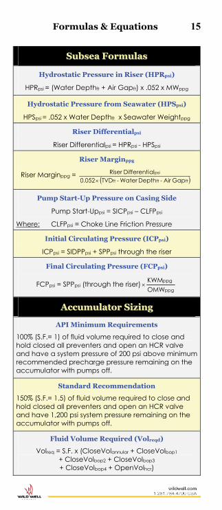
SSuubbsseeaa FFoorrmmuullaass
Hydrostatic Pressure in Riser (HPRpsi)
HPRpsi = (Water Depthft + Air Gapft) x .052 x MWppg
Hydrostatic Pressure from Seawater (HPSpsi)
HPSpsi = .052 x Water Depthft x Seawater Weightppg
Riser Differentialpsi
Riser Differentialpsi = HPRpsi - HPSpsi
Riser Marginppg
Riser Marginppg = ftftft
psi
Gap Air - Depth Water - TVD0.052alDifferenti Riser
Pump Start-Up Pressure on Casing Side
Pump Start-Uppsi = SICPpsi – CLFPpsi
Where: CLFPpsi = Choke Line Friction Pressure
Initial Circulating Pressure (ICPpsi)
ICPpsi = SIDPPpsi + SPPpsi through the riser
Final Circulating Pressure (FCPpsi)
FCPpsi = SPPpsi (through the riser)ppg
ppg
OMW KWM
AAccccuummuullaattoorr SSiizziinngg
API Minimum Requirements
100% (S.F.= 1) of fluid volume required to close and hold closed all preventers and open an HCR valve and have a system pressure of 200 psi above minimum recommended precharge pressure remaining on the accumulator with pumps off.
Standard Recommendation
150% (S.F.= 1.5) of fluid volume required to close and hold closed all preventers and open an HCR valve and have 1,200 psi system pressure remaining on the accumulator with pumps off.
Fluid Volume Required (Volreqd)
Volreq = S.F. x (CloseVolannular + CloseVolbop1 + CloseVolbop2 + CloseVolbop3 + CloseVolbop4 + OpenVolhcr)

16 Formulas & Equations
AAccccuummuullaattoorr SSiizziinngg,, ccoonnttiinnuueedd
Accumulator Volume Required
Usable hydraulic fluid for operation of blowout preventer equipment is affected by system pressure and nitrogen precharge. If the nitrogen precharge is at the correct (recommended) precharge, multiply the sizing factor from the table below times the fluid volume required to operate a specified number of BOP functions (Volreq) will provide the required total accumulator volume.
Accumulator System
Pressure
Minimum Recommended
Precharge Pressure
Useable Fluid
Accumulator Size Factor*
3,000 1,000 1 50.0%* 2 5,000 1,500 1 58.2%* 1.72
* Based on minimum system pressure of 200 psi over precharge. 1 All precharge pressures should be in compliance with API 16D. Precharge Pressure: The accumulator bottles filled with only precharge gas at its initial pressure and ambient temperature. The precharge pressure should be specified with a temperature. Precharge pressure is not to exceed the working pressure of the accumulator. Any precharge pressure less than the working pressure of the accumulator may be used as long as the functional requirements of pressure and volume and minimum design factors are satisfied.
Accumulator Volume Example
If the total fluid required for a BOP stack is 33 gallons, including the safety factor, and the accumulator has an operating pressure of 3,000 psi with a 1,000 psi minimum precharge, the accumulator volume required is 33 gallons times the size factor of 2, or 66 gallons.
Accumulator Usable Fluid Volume
Usable Volume = VR(Volume Required) x Bottle Volume Where VR
=psi
psi
psi
psi
Press operatingMax Press Precharge -
Press operating MinPress Precharge
MMuudd && CCeemmeenntt FFoorrmmuullaass
Barite (100 lb sx) Per 100 bbl Required for Weight-Up
Sacks per 100 bbl = ppg
ppgppg
KWM - 35OMW - KWM1,470
Hematite (100 lb sx) Per 100 bbl Required for Weight-Up
Sacks per 100 bbl = ppg
ppgppg
KWM - 40OMW - KWM1,680

Formulas & Equations 17
MMuudd && CCeemmeenntt FFoorrmmuullaass,, ccoonnttiinnuueedd
Pit Volume Increase per 100 bbl (V100bbl) due to Weight-Up with Barite
V100bbl = ppg
ppgppg
KWM - 35OMW - KWM100
Final Mud Weight (MWppg) when Mixing Two Densities of Mud
MWppg = ( ) ( )
bbl+bbl
ppgbblppgbbl
Vol2Vol1MW2×Vol2 +MW1×Vol1
Initial Mud Volume Required (IVolbbl) to Build a Final Volume of Mud with Barite
IVolbbl = ppg
ppgbbl
OMW - 35KWM-35 Vol Final
Sacks of (94 lb) Cement Required
Sacks94lb = cf/sk
ftbbl/ftcf/bbl
Yield %Excess x Length x Cap x 5.615
Mix Fluid Requirement
Mix Fluidbbl = gal/bbl
gal/sk
42 Req FluidMix Mix to Sacks No.
Balanced Plug (Cement, Barite, etc.)
A) Calculate volume of plug:
PlugVolbbl = Plug Lengthft X Hole Capbbl/Ft
B) Calculate length of balanced column :
Column Lengthft = bbl/ftbbl/ft
bbl
Cap DP Cap AnnulusPlugVol
C) Calculate total string volume to balance:
VolBalancebbl =(Plug Bottom Depthft – Column Lengthft) X DPcapbbl/Ft
D) Calculate ratio of spacer inside and outside of string:
Spacer Ratio = bbl/ft
bbl/ft
Cap DPCap Annular
E) Calculate displacement volume:
DisplVolbbl = VolBalancebbl – Spacer Behindbbl

18 Formulas & Equations
HHyyddrraauulliiccss FFoorrmmuullaass
Annular Velocity (AVft/min)
Vft/min = 22inin PipeOD HoleOD
Rate Pump24.51
- gpm
Hydraulic Horsepower (HHP)
HHP = 1,714
Pressure Pump x Q psigpm
HHP = 40.8
Pressure Pump x Q psibpm
Rules of Thumb
TTrriippppiinngg RRuulleess ooff TThhuummbb Ideally, drillers would like to keep bottomhole hydrostatic pressure constant during the trip out (POOH) and the trip in (RIH). However, this is impossible from the operational standpoint because of swab and surge pressures. Most tripping rules-of-thumb are closely associated with maintaining a safe hydrostatic overbalance that neither causes a kick nor lost circulation.
Slug Mud Weight Rule of Thumb
Slug mud weight is generally one ppg higher than the hole mud weight, with the objective being to unbalance the DP/annulus U-tube by enough to pull dry pipe. The condition of the mud, related to drill solids, and/or the mud weight range could influence the driller to accept less than one ppg.

Rules of Thumb 19
SSttuucckk PPiippee The causes of stuck pipe are broadly classified as differential or mechanical, and good monitoring and operating practices will minimize both types of pipe sticking. Differential sticking is caused by mud pressure overbalance and is influenced by drilling practices, type mud solids, permeability, bottom-hole assembly clearance, coefficient of friction and the lubricating characteristics of mud. Mechanical sticking is caused by deterioration of hole stability (shale problems, hole cleaning, etc.) and/or directional (crooked-hole) problems.
Rule of Thumb for Differentially Stuck Pipe
The estimated force required to pull free is equal to the contact force per unit length, times the length of pipe in contact with permeable formation times the coefficient of friction. This estimate tends to be more accurate in a straight hole than in a directional well.
Estimating Formula for Differential Sticking
Fdiff = K (P) Area Where: K = Sticking coefficient (0.2 water base mud) (P) = Differential pressure (psi) d = Diameter (inches) L = Permeable zone length (feet) Area = Contact area (inches 2)
Area =
3d
ft.in12L
(assume ⅓ of the drill collar circumference is buried) Circumference = x Diameter
Conclusion: Force to pull free increases as the length of pipe in contact with permeable formation increases, and as the coefficient of friction between pipe and wall increases.
Example
Given 6 ¼" DC:
545.63
25.61416.33
d
(round to 6.5)
P = 200 psi (approx. 0.5 ppg overbalance at 8,000 ft) L = 200 ft (of permeable zone)
Fdiff = 0.2 x 200psi x 200ft x 12in./ft x 6.5in. = 624,000lbs

20 Rules of Thumb
FFrreeee PPooiinntt aanndd SSttrreettcchh EEssttiimmaatteess When the drill string is stuck, the free point method can be used to estimate the amount of free pipe in the hole.
Begin by pulling on the pipe with an initial force (Fi) that is at least 1,000 pounds more than the hanging weight of the string, and make a reference mark on the string. Increase the pull by increments (for example, 5,000 lbs) to final force (Ff) to determine a measurable stretch. Mark the string again, measure the distance between the marks and record as the stretch (S) in inches. Record the difference between Ff and Fi as the pull increment (PI). The amount of free pipe (L) in 1,000’s of feet below the rotary can then be estimated. These estimates tend to be more accurate in straight holes than in directional wells.
Estimating Formula
The formula for free pipe length L is:
L = PI
IDODS9635.122
The formula for pipe stretch S is:
S =
)ID(OD1.9635
LPl22
Where: L = Length of free pipe (1,000s ft) S = Stretch (inches) OD = OD of the pipe (inches) ID = ID of the pipe (inches) Pl = Pull increment (1,000s lbs) = Ff - Fi
Example
Given: Drillpipe size = 5", 19.5 lb/ft Fi = 5,000 lb OD = 5" Ff = 35,000 lb ID = 4.276" S = 12" Calculate:
PI = 35 – 5 = 30
L = 30
284.1825129635.1 = 5.27 thousand feet

Rules of Thumb 21
EEssttiimmaattiinngg TTeemmppeerraattuurree DDrroopp AAccrroossss aa CChhookkee oorr OOrriiffiiccee
Rule of Thumb
The temperature drop across a choke or orifice is about one degree Fahrenheit (F) per each pressure drop of one atmosphere (rounded at 15 psi).
Estimating Formula
F1atm
PP T Lhdrop
Where: Tdrop = Temperature drop (degrees) Ph = Gas pressure before the choke (psi) PL = Gas pressure after the choke (psi) atm = Atmospheric pressure (15 psi)
Example
Calculate temperature drop if the gas pressure is reduced from 1,000 psi to 500 psi across a choke.
Tdrop = F1atm
500)(1,000
= 33 x 1°F = 33°F temperature drop
BBiitt NNoozzzzllee PPrreessssuurree LLoossss
2
2
Ax10858Qxρ P
Where: ΔP = Pressure (psi) ρ = Density (ppg) Q = Circulation rate (gal/min) A = Area of the nozzle (in2)

22 Rules of Thumb
EEssttiimmaattiinngg GGaass WWeellll FFllooww RRaatteess
Rule of Thumb
The approximate flow rate (in mmscfd) of a gas well through a blowdown line choke can be estimated by multiplying 24 hours/day, times the tubing pressure plus 15, times the square of the choke size in inches and divide by 1,000.
Estimating Formula
Q = 1,000
(Dch) x 15) (PL x 24 2
Where: Q = Flowrate (mmscfd) PL = Pressure upstream of choke (psi) Dch = Choke size (inches)
Example
Calculate the estimated flowrate of a gas well, given that tubing pressure is 3,500 psi, and choke size is 1/4.
Q = 1,000
(0.25) x 15) (3,500 x 24 2
= 5.273 mmscfd
AArreeaa ooff aa CCiirrccllee ((iinn22))
0.7854 x D2
or π D2/4
or π R2 Where:
D = diameter (inches) R = radius (inches)
Rules of Thumb 23
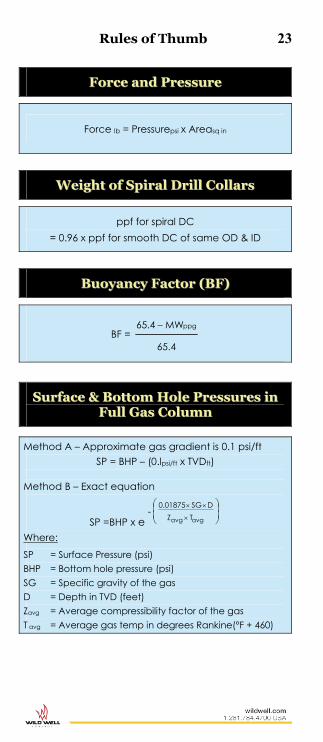
FFoorrccee aanndd PPrreessssuurree
Force lb = Pressurepsi x Areasq in
WWeeiigghhtt ooff SSppiirraall DDrriillll CCoollllaarrss
ppf for spiral DC = 0.96 x ppf for smooth DC of same OD & ID
BBuuooyyaannccyy FFaaccttoorr ((BBFF))
BF = 65.4
MW65.4 ppg
SSuurrffaaccee && BBoottttoomm HHoollee PPrreessssuurreess iinn FFuullll GGaass CCoolluummnn
Method A – Approximate gas gradient is 0.1 psi/ft SP = BHP – (0.lpsi/ft x TVDft)
Method B – Exact equation
SP =BHP x e -
avgavg TZD SG 0.01875
Where: SP = Surface Pressure (psi) BHP = Bottom hole pressure (psi) SG = Specific gravity of the gas D = Depth in TVD (feet) Zavg = Average compressibility factor of the gas T avg = Average gas temp in degrees Rankine(°F + 460)

24 Rules of Thumb
PPiippee EElloonnggaattiioonn DDuuee ttoo TTeemmppeerraattuurree Since the well has higher temperatures than the air above ground, an elongation will take place.
Rule of Thumb
Pipe will elongate about 0.83 inches, per 100 feet of length, per 100 degree F increase in temperature. Knowing the surface temperature and the average temperature of the well, the elongation can be estimated.
Note: Elongation (stretch) is also caused by the hanging weight of pipe.
Estimating Formulas
FSTTVDft100
F1BHT
2STBHTTa
T = Ta – Surface Temp
TLFin/in0000069.012L ft/inT
83.0F100
Tft 100
LLT
Where: BHT = Bottomhole temperature (°F) Depth = True vertical depth (ft) ST = Surface temperature (°F) Ta = Average temperature (°F) T = Change in average temperature (°F) LT = Elongation (inches) L = Length of pipe (ft)

Rules of Thumb 25
MMyy RRuulleess ooff TThhuummbb

26 P
ipe
Siz
e
In.
No
m.
Wt.
L
b/F
t
Wa
ll
Th
ick
. In
.
Pip
e
ID
In.
Pla
in
En
d W
t.
Lb
/Ft
Up
set
Wt.
L
b
Pip
e E
nd
D
ia.
ID
Pip
e E
nd
D
ia.
OD
AP
I D
esi
gn
ati
on
To
ol
Jo
int
wit
h T
oo
l J
oin
t w
ith
ou
t T
oo
l J
oin
t O
D
In.
ID
In.
Len
gth
F
t.W
eigh
t L
bC
apac
ity
Bb
ls/F
t D
isp
l. B
bls
/Ft
Cap
acit
y B
bls
/Ft
Dis
pl.
Bb
ls/F
t
Ex
tern
al
Up
set
– G
rad
e E
2 ⅞
10
.40
0.36
2 2.
151
9.72
2.
40
2.15
1 3.
219
OH
3.87
5 2.
156
1.29
34
.99
0.00
451
0.00
389
0.00
449
0.00
353
3 ½
13
.30
0.36
8 2.
764
12.3
1 4.
00
2.60
2 3.
824
NC
38
(IF)
4.75
0 2.
688
1.54
61
.10
0.00
741
0.00
515
0.00
742
0.00
448
3 ½
15
.50
0.44
9 2.
602
14.6
3 2.
80
2.60
2 3.
824
NC
38
(IF)
5.00
0 2.
563
1.59
74
.82
0.00
658
0.00
606
0.00
658
0.00
532
Inte
rna
l E
xte
rna
l U
pse
t –
Gra
de
X
5 19
.50
0.36
2 4.
276
17.9
3 16
.80
3.65
3 5.
188
NC
50
(EH)
6.
375
3.50
0 1.
65
120.
23
0.01
745
0.00
784
0.01
776
0.00
652
Ex
tern
al
Up
set
– G
rad
e G
4 14
.00
0.33
0 3.
340
12.9
3 14
.40
3.06
3 4.
625
NC
46
(IF)
6.00
0 3.
250
1.70
10
8.76
0.
0108
2 0.
0058
7 0.
0108
4 0.
0047
1 4
½
16.6
0 0.
337
3.82
6 14
.98
17.2
0 3.
563
5.18
8 N
C 5
0 (IF
) 6.
375
3.75
0 1.
67
113.
10
0.01
421
0.00
663
0.01
422
0.00
545
Inte
rna
l E
xte
rna
l U
pse
t –
Gra
de
G
4 ½
20
.00
0.43
0 3.
640
18.6
9 17
.60
2.81
3 4.
250
NC
46
(EH)
6.
250
2.50
0 1.
71
142.
46
0.01
252
0.00
830
0.01
287
0.00
680
5 19
.50
0.36
2 4.
276
17.9
3 16
.80
3.56
3 5.
188
NC
50
(IF)
6.62
5 2.
750
1.70
15
7.37
0.
0171
9 0.
0082
7 0.
0177
6 0.
0065
2 5
25.6
0 0.
500
4.00
0 24
.03
15.4
0 3.
313
5.18
8 5
½ F
H 7.
250
3.25
0 1.
82
188.
17
0.01
523
0.01
075
0.01
554
0.00
874
5 25
.60
0.50
0 4.
000
24.0
3 15
.40
3.31
3 5.
188
5 ½
FH
7.25
0 3.
500
1.82
17
9.97
0.
0153
5 0.
0106
6 0.
0155
4 0.
0087
4 5
½
21.9
0 0.
361
4.77
8 19
.81
21.0
0 3.
813
5.56
3 5
½ F
H 7.
250
3.50
0 1.
79
184.
41
0.02
162
0.00
925
0.02
218
0.00
721
Inte
rna
l E
xte
rna
l U
pse
t –
Gra
de
S
5 ½
21
.90
0.36
1 4.
778
19.8
1 21
.00
3.81
3 5.
563
HT 5
5 7.
000
4.00
0 2.
33
199.
19
0.02
172
0.00
925
0.02
218
0.00
721
5 ½
24
.70
0.41
5 4.
670
22.5
4 18
.40
3.81
3 5.
563
HT 5
5 7.
000
3.75
0 2.
31
210.
15
0.02
067
0.01
042
0.02
119
0.00
820
5 ⅞
23
.40
0.36
1 5.
153
7.
000
4.25
0.
0252
1 0.
0097
1 0.
0257
9 0.
0077
3 6 ⅝
25
.20
0.33
0 5.
965
22.1
9 25
.87
5.31
5 6.
929
HT 6
5 8.
000
5.00
0 2.
35
240.
81
0.03
385
0.01
078
0.03
456
0.00
807
6 ⅝
27
.70
0.36
2 5.
901
24.2
1 24
.00
5.31
5 6.
929
HT 6
5 8.
000
4.75
0 2.
39
284.
15
0.03
297
0.01
194
0.03
383
0.00
881
Drillpipe – Range II

Drillpipe Capacity & Displacement 27
\
DP OD (In).
Weight (ppf)
ID Tube (In.)
DP Capacity (bbl/ft)
Displacement (bbl/ft)
Closed-End
(bbl/ft)
2 ⅜ 4.85 1.995 0.00387 0.0016 0.0055 6.65 1.815 0.00320 0.0023 0.0055
2 ⅞
6.45 2.469 0.00592 0.0021 0.0080 6.85 2.441 0.00579 0.0022 0.0080 8.35 2.323 0.00524 0.0028 0.0080
10.40 2.151 0.00449 0.0035 0.0080
3 ½
8.50 3.063 0.00911 0.0028 0.0119 9.50 2.992 0.00870 0.0032 0.0119
11.20 2.900 0.00817 0.0037 0.0119 13.30 2.764 0.00742 0.0045 0.0119 15.50 2.602 0.00658 0.0053 0.0119
4 11.85 3.476 0.01174 0.0038 0.0155 14.00 3.340 0.01084 0.0047 0.0155 15.70 3.240 0.01020 0.0053 0.0155
4 ½
12.75 4.000 0.01554 0.0041 0.0197 13.75 3.958 0.01522 0.0045 0.0197 16.60 3.826 0.01422 0.0055 0.0197 20.00 3.640 0.01287 0.0068 0.0197
5 16.25 4.408 0.01888 0.0054 0.0243 19.50 4.276 0.01776 0.0065 0.0243 20.50 4.214 0.01725 0.0070 0.0243
5 ½ 21.90 4.778 0.02218 0.0072 0.0294 24.70 4.670 0.02119 0.0082 0.0294
5 ⅞ 23.40 5.153 0.02579 0.0077 0.0335 26.30 5.045 0.02472 0.0088 0.0335 28.67 4.875 0.02309 0.0104 0.0335
6 ⅝ 22.20 6.065 0.03573 0.0069 0.0426 25.20 5.965 0.03456 0.0081 0.0426 31.90 5.761 0.03224 0.0104 0.0426
7 ⅝ 29.25 6.969 0.04718 0.0093 0.0565
Note: Capacity and displacement value are without tool joint.

28 No
min
al
Siz
e
In.
No
min
al
Tu
be
Dim
en
sio
ns
To
ol
Jo
int
Ap
pro
x.
We
igh
t T
ub
e &
Jo
ints
lb
/ft
Ma
ke
-up
T
orq
ue
(ft-
lb)
Ca
pa
city
b
bls
/ft
Dis
pla
cem
ent
bb
ls/f
t In
sid
e D
ia.
In
. W
all
T
hic
kn
ess
In
. C
on
ne
ctio
n S
ize
In
. O
uts
ide
D
ia.
In.
Insi
de
D
ia.
In.
3 ½
2
1 /16
0.
719
NC
38
(3 ½
IF)
4 ¾
2
3 /16
25
.3
9,90
0 0.
0042
0.
0092
3
½
2 ¼
0.
625
NC
38
(3 ½
IF)
4 ¾
2 ⅜
23
.2
9,90
0 0.
0050
0.
0084
4
2 9 /
16
0.71
9 N
C 4
0 (4
FH
) 5
¼
2 11
/ 16
27.2
13
,250
0.
0073
0.
0100
4
½
2 ¾
0.
875
NC
46
(4 IF
) 6
¼
2 ⅞
41
.0
21,8
00
0.00
74
0.01
49
5 3
1.00
0 N
C 5
0 (4
½ IF
) 6 ⅝
3
1 /16
49
.3
29,4
00
0.00
88
0.01
79
5 ½
3 ⅜
1.
063
5 ½
FH
7
3 ½
57
.0
33,2
00
0.01
11
0.02
07
6 ⅝
4
½
1.06
3 6 ⅝
FH
8 4
½
70.8
46
,900
0.
0196
0.
0257
Heavy-Weight Drillpipe

29
OD
ID
C
ap
aci
ty
1 ½
" 0.
0022
1
¾"
0.00
30
2"
0.00
39
2 ¼
"0.
0049
2 ½
"0.
0061
2 ¾
"0.
0073
3"0.
0087
3 ¼
" 0.
0103
3
½"
0.01
19
3 ¾
"0.
0137
4"
Wt l
b/f
t 36
.7
34.5
32
.0
29.2
-
- -
- -
- D
isp b
bl/f
t 0.
0133
0.
0125
0.
0116
0.
0106
-
- -
- -
- 4
¼"
Wt l
b/f
t 42
.2
40.0
37
.5
34.7
-
- -
- -
- D
isp b
bl/f
t 0.
0153
0.
0145
0.
0136
0.
0126
-
- -
- -
- 4
½"
Wt l
b/f
t 48
.1
45.9
43
.4
40.6
-
- -
- -
- D
isp b
bl/f
t 0.
0175
0.
0167
0.
0158
0.
0148
-
- -
- -
- 4
¾"
Wt l
b/f
t 54
.3
52.1
49
.6
46.8
43
.6
- -
- -
- D
isp b
bl/f
t 0.
0197
0.
0189
0.
0181
0.
0170
0.
0159
-
- -
- -
5"
Wt l
b/f
t 60
.8
58.6
56
.1
53.3
50
.1
- -
- -
- D
isp b
bl/f
t 0.
0221
0.
0213
0.
0204
0.
0194
0.
0182
-
- -
- -
5 ¼
" W
t lb
/ft
67.6
65
.4
62.9
60
.1
56.9
53
.4
- -
- -
Disp
bbl
/ft
0.02
46
0.02
38
0.02
29
0.02
19
0.02
07
0.01
94
- -
- -
5 ½
" W
t lb
/ft
74.8
72
.6
70.1
67
.3
64.1
60
.6
56.8
-
- -
Disp
bbl
/ft
0.02
72
0.02
64
0.02
55
0.02
45
0.02
33
0.02
21
0.02
07
- -
- 5
¾"
Wt l
b/f
t 82
.3
80.1
77
.6
74.8
71
.6
68.1
64
.3
- -
- D
isp b
bl/f
t 0.
0299
0.
0291
0.
0282
0.
0272
0.
0261
0.
0248
0.
0234
-
- -
6"
Wt l
b/f
t 90
.1
87.9
85
.4
82.6
79
.4
75.9
72
.1
67.9
63
.4
- D
isp b
bl/f
t 0.
0328
0.
0320
0.
0311
0.
0301
0.
0289
0.
0276
0.
0262
0.
0247
0.
0231
-
6 ¼
" W
t lb
/ft
98.0
95
.8
93.3
90
.5
87.3
83
.8
80.0
75
.8
71.3
-
Disp
bbl
/ft
0.03
56
0.03
49
0.03
39
0.03
29
0.03
18
0.03
05
0.02
91
0.02
76
0.02
59
- 6
½"
Wt l
b/f
t 10
7.0
104.
8 10
2.3
99.5
96
.3
92.8
89
.0
84.8
80
.3
- D
isp b
bl/f
t 0.
0389
0.
0381
0.
0372
0.
0362
0.
0350
0.
0338
0.
0324
0.
0308
0.
0292
-
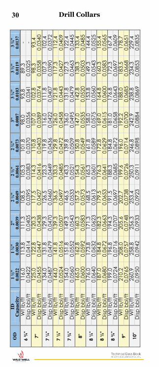
Drill Collars
Sp
ira
l D
rill
Co
lla
rs
App
rox.
Disp
lace
men
t of
Spira
l Dril
l Col
lar i
n bb
ls/ft
747
,2
56.2ID-
OD
22
30 O
D
ID
Ca
pa
city
1
½"
0.00
22
1 ¾
" 0.
0030
2"
0.
0039
2
¼"
0.00
492
½"
0.00
612
¾"
0.00
733"
0.00
873
¼"
0.01
03
3 ½
" 0.
0119
3
¾"
0.01
37
6 ¾
" W
t lb
/ft
116.
0 11
3.8
111.
3 10
8.5
105.
3 10
1.8
98.0
93
.8
89.3
-
Disp
bbl
/ft
0.04
22
0.04
14
0.04
05
0.03
95
0.03
83
0.03
70
0.03
56
0.03
41
0.03
25
- 7"
W
t lb
/ft
125.
0 12
2.8
120.
3 11
7.5
114.
3 11
0.8
107.
0 10
2.8
98.3
93
.4
Disp
bbl
/ft
0.04
55
0.04
47
0.04
38
0.04
27
0.04
16
0.04
03
0.03
89
0.03
74
0.03
58
0.03
40
7 ¼
" W
t lb
/ft
134.
0 13
1.8
129.
3 12
6.5
123.
3 11
9.8
116.
0 11
1.8
107.
3 10
2.4
Disp
bbl
/ft
0.04
87
0.04
79
0.04
70
0.04
60
0.04
49
0.04
36
0.04
22
0.04
07
0.03
90
0.03
72
7 ½
" W
t lb
/ft
144.
0 14
1.8
139.
3 13
6.5
133.
3 12
9.8
126.
0 12
1.8
117.
3 11
2.4
Disp
bbl
/ft
0.05
24
0.05
16
0.05
07
0.04
97
0.04
85
0.04
72
0.04
58
0.04
43
0.04
27
0.04
09
7 ¾
" W
t lb
/ft
154.
0 15
1.8
149.
3 14
6.5
143.
3 13
9.8
136.
0 13
1.8
127.
3 12
2.4
Disp
bbl
/ft
0.05
60
0.05
52
0.05
43
0.05
33
0.05
21
0.05
09
0.04
95
0.04
79
0.04
63
0.04
45
8"
Wt l
b/f
t 16
5.0
162.
8 16
0.3
157.
5 15
4.3
150.
8 14
7.0
142.
8 13
8.3
133.
4 D
isp b
bl/f
t 0.
0600
0.
0592
0.
0583
0.
0573
0.
0561
0.
0549
0.
0535
0.
0520
0.
0503
0.
0485
8
¼"
Wt l
b/f
t 17
6.0
173.
8 17
1.3
168.
5 16
5.3
161.
8 15
8.0
153.
8 14
9.3
144.
4 D
isp b
bl/f
t 0.
0640
0.
0632
0.
0623
0.
0613
0.
0601
0.
0589
0.
0575
0.
0560
0.
0543
0.
0525
8
½"
Wt l
b/f
t 18
7.0
184.
8 18
2.3
179.
5 17
6.3
172.
8 16
9.0
164.
8 16
0.3
155.
4 D
isp b
bl/f
t 0.
0680
0.
0672
0.
0663
0.
0653
0.
0641
0.
0629
0.
0615
0.
0600
0.
0583
0.
0565
8
¾"
Wt l
b/f
t 19
9.0
196.
8 19
4.3
191.
5 18
8.3
184.
8 18
1.0
176.
8 17
2.3
167.
4 D
isp b
bl/f
t 0.
0724
0.
0716
0.
0707
0.
0697
0.
0685
0.
0672
0.
0658
0.
0643
0.
0697
0.
0609
9"
W
t lb
/ft
210.
2 20
8.0
205.
6 20
2.7
199.
6 19
6.0
192.
2 18
8.0
183.
5 17
8.7
Disp
bbl
/ft
0.07
65
0.07
57
0.07
48
0.07
38
0.07
26
0.07
14
0.07
00
0.06
85
0.06
68
0.06
51
10"
Wt l
b/f
t 26
0.9
258.
8 25
6.3
253.
4 25
0.3
246.
8 24
2.9
238.
8 23
4.3
229.
4 D
isp b
bl/f
t 0.
0950
0.
0942
0.
0933
0.
0923
0.
0911
0.
0898
0.
0884
0.
0869
0.
0853
0.
0835
Drill Collars
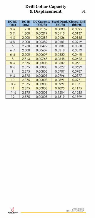
Drill Collar Capacity & Displacement 31
DC OD (In.)
DC ID (In.)
DC Capacity (bbl/ft)
Steel Displ. (bbl/ft)
Closed-End (bbl/ft)
3 ⅛ 1.250 0.00152 0.0080 0.0095 3 ¾ 1.500 0.00219 0.0115 0.0137 4 ⅛ 2.000 0.00389 0.0126 0.0165 4 ¾ 2.000 0.00389 0.0181 0.0219
6 2.250 0.00492 0.0301 0.0350 6 ¼ 2.500 0.00607 0.0318 0.0379 6 ½ 2.500 0.00607 0.0350 0.0410
8 2.813 0.00768 0.0545 0.0622 8 ¼ 2.875 0.00803 0.0589 0.0661 8 ½ 2.875 0.00803 0.0622 0.0629
9 2.875 0.00803 0.0707 0.0787 9 ½ 2.875 0.00803 0.0796 0.0877 10 2.875 0.00803 0.0891 0.0971
10 ½ 2.875 0.00803 0.0991 0.1071 11 2.875 0.00803 0.1095 0.1175
11 ½ 2.875 0.00803 0.1204 0.1285 12 2.875 0.00803 0.1319 0.1399
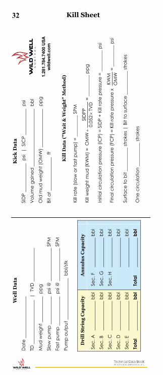
32
We
ll D
ata
K
ick
Da
ta
Dat
e
SID
P
psi
| S
ICP
p
si
TD
| T
VD
Vol
ume
gain
ed
bbl
Mud
wei
ght
p
pg
O
ld m
ud w
eigh
t (O
MW
)
ppg
Slow
pum
p
p
si @
SPM
Bi
t at
f
t
Fast
pum
p
p
si @
SPM
Pum
p ou
tput
bbl
/stk
Kil
l D
ata
("W
ait
& W
eig
ht"
Me
tho
d)
Kill r
ate
(slo
w o
r fas
t pum
p) =
___
____
__ S
PM
Kill w
eigh
t mud
(KW
M) =
TV
D05
2.0
SID
PPO
MW
= __
____
___
ppg
Initi
al c
ircul
atio
n pr
essu
re (I
CP)
= S
IDP
+ Ki
ll rat
e pr
essu
re =
___
____
__ p
si
Fina
l circ
ulat
ion
pres
sure
(FC
P) =
Kill
rate
pre
ssur
e x
OM
WKW
M=
____
____
_ ps
i
Surfa
ce to
bit
____
____
__ st
roke
s | B
it to
surfa
ce _
____
____
_ st
roke
s
One
circ
ulat
ion
____
____
__ st
roke
s
Dri
ll S
trin
g C
ap
aci
ty
An
nu
lus
Ca
pa
city
Sec.
A
bbl
Sec.
B
bbl
Sec.
C
bbl
Sec.
D
bbl
Sec.
E
bbl
Tota
l
b
bl
Sec.
F
bbl
Sec.
G
bbl
Sec.
H
bbl
b
bl
b
bl
Tota
l
b
bl
Kill Sheet
1.28
1.78
4.74
00 U
SA
w
ildw
ell.c
om

33 K
ill
Sch
ed
ule
("W
ait
& W
eig
ht"
Me
tho
d)
Str
okes
V
olu
mes
D
rill
pip
e P
ress
S
trok
es
V
olu
me
D
rill
ipe
Pre
ss
0
0
ICP
To B
it
FCP
Ca
sing
size
Set a
t
Bit a
t ft
TD a
t ft
NO
TE: E
nlar
ge p
age
by 1
25%
to
get 8
½ x
11" f
ull-s
ize w
orks
heet
. Kill Sheet
STRO
KES
KILL
CHA
RT
PRESSURE

34 u
bin
g S
ize
N
orm
al
Wei
gh
t
Gra
de
W
all
T
hic
k.
In.
Insi
de
Dia
. In
.
Th
rea
ded
Co
up
lin
g
Co
lla
pse
R
esis
tan
ce
PS
I
Inte
rna
l Y
ield
P
ress
ure
P
SI
Jo
int
Yie
ld S
tre
ng
th
Ca
pa
city
b
bl/
ft
Dis
pla
cem
ent
Nom
inal
In
. O
D I
n.
T&
C
Non
-U
pset
lb
/ft
T&
C
Ups
et
lb/f
t
Dri
ft
Dia
In
.
Co
up
lin
g O
uts
ide
dia
. T
&C
N
on-U
pse
t L
b
T&
C
Ups
et
Lb
T&
C
Non
-Up
set
bbl/
ft
T&
C
Ups
et
bbl/
ft
No
n-
Up
set
In.
Up
set
Re
a.
In.
Up
set
Sp
ec I
n.
¾
1.05
0 1.
14
1.20
H-
40
0.11
3 .8
24
.730
1.
313
1.66
0
7,68
0 7,
530
6,36
0 13
,300
0.
0006
6 0.
0004
1 0.
0004
4
1.05
0 1.
14
1.20
J-
55
0.11
3 .8
24
.730
1.
313
1.66
0
10,5
60
10,5
60
8,74
0 18
,290
0.
0006
6 0.
0004
1 0.
0004
4
1.05
0 1.
14
1.20
C
-75
0.11
3 .8
24
.730
1.
313
1.66
0
14,4
10
14,1
30
11,9
20
24,9
40
0.00
066
0.00
041
0.00
044
1.05
0 1.
14
1.20
N
-80
0.11
3 .8
24
.730
1.
313
1.66
0
15,3
70
15,0
70
12,7
10
26,6
10
0.00
066
0.00
041
0.00
044
1
1.31
5 1.
70
1.80
H-
40
0.13
3 1.
049
.955
1.
660
1.90
0
7,27
0 7,
080
10,9
60
19,7
60
0.00
107
0.00
062
0.00
065
1.31
5 1.
70
1.80
J-
55
0.13
3 1.
049
.955
1.
660
1.90
0
10,0
00
9,73
0 15
,060
27
,160
0.
0010
7 0.
0006
2 0.
0006
5
1.31
5 1.
70
1.80
C
-75
0.13
3 1.
049
.955
1.
660
1.90
0
13,6
40
13,2
70
20,5
40
37,0
40
0.00
107
0.00
062
0.00
065
1.31
5 1.
70
1.80
N
-80
0.13
3 1.
049
.955
1.
660
1.90
0
14,5
50
14,1
60
21,9
10
39,5
10
0.00
107
0.00
062
0.00
065
1 ¼
1.66
0 2.
30
2.40
H-
40
0.12
5 1.
410
1.28
6 2.
054
2.20
0
5,57
0 5,
270
0.00
193
1.66
0 2.
30
2.40
H-
40
0.14
0 1.
380
1.28
6 2.
054
2.20
0
6,18
0 5,
900
15,5
30
26,7
40
0.00
185
0.00
084
0.00
087
1.66
0 2.
30
2.40
J-
55
0.14
0 1.
380
1.28
6 2.
054
2.20
0
8,49
0 8,
120
21,3
60
36,7
70
0.00
185
0.00
084
0.00
087
1.66
0 2.
30
2.40
C
-75
0.14
0 1.
380
1.28
6 2.
054
2.20
0
11,5
80
11,0
70
29,1
20
50,1
40
0.00
185
0.00
084
0.00
087
1.66
0 2.
30
2.40
N
-80
0.14
0 1.
380
1.28
6 2.
054
2.20
0
12,3
60
11,8
10
31,0
60
53,4
80
0.00
185
0.00
084
0.00
087
API Tubing

35 T
ub
ing
Siz
e
No
rma
l W
eig
ht
Gra
de
W
all
T
hic
k.
In.
Insi
de
Dia
. In
.
Th
rea
ded
Co
up
lin
g
Co
lla
pse
R
esis
tan
ce
PS
I
Inte
rna
l Y
ield
P
ress
ure
P
SI
Jo
int
Yie
ld S
tre
ng
th
Ca
pa
city
b
bl/
ft
Dis
pla
cem
ent
Nom
inal
In
. O
D I
n.
T&
C
Non
-U
pset
lb
/ft
T&
C
Ups
et
lb/f
t
Dri
ft
Dia
In
.
Co
up
lin
g O
uts
ide
dia
. T
&C
N
on-U
pse
t L
b
T&
C
Ups
et
Lb
T&
C
Non
-Up
set
bbl/
ft
T&
C
Ups
et
bbl/
ft
No
n-
Up
set
In.
Up
set
Re
a.
In.
Up
set
Sp
ec I
n.
1
1 /2
1.90
0 2.
75
2.90
H-
40
0.14
5 1.
610
1.51
6 2.
200
2.50
0
5,64
0 5,
340
19,0
90
31,9
80
0.00
252
0.00
100
0.00
106
1.90
0 2.
75
2.90
J-
55
0.14
5 1.
610
1.51
6 2.
200
2.50
0
7,75
0 7,
350
26,2
50
43,9
70
0.00
252
0.00
100
0.00
106
1.90
0 2.
75
2.90
C
-75
0.14
5 1.
610
1.51
6 2.
200
2.50
0
10,5
70
10,0
20
35,8
00
59,9
60
0.00
252
0.00
100
0.00
106
1.90
0 2.
75
2.90
N
-80
0.14
5 1.
610
1.51
6 2.
200
2.50
0
11,2
80
10,6
80
38,1
30
63,9
50
0.00
252
0.00
100
0.00
106
2 1 /
16
2.06
3
H-
40
0.15
6 1.
751
7,77
0 7,
630
0.00
298
2.06
3
J-
55
0.15
6 1.
751
7,69
0 7,
280
0.00
298
2.06
3
C
-75
0.15
6 1.
751
10,4
80
9,92
0
0.
0029
8
2.06
3
N
-80
0.15
6 1.
751
11,1
80
10,5
90
0.00
298
API Tubing

36 T
ub
ing
Siz
e
No
rma
l W
eig
ht
Gra
de
W
all
T
hic
k.
In.
Insi
de
Dia
. In
.
Th
rea
ded
Co
up
lin
g
Co
lla
pse
R
esis
tan
ce
PS
I
Inte
rna
l Y
ield
P
ress
ure
P
SI
Jo
int
Yie
ld S
tre
ng
th
Ca
pa
city
b
bl/
ft
Dis
pla
cem
ent
Nom
inal
In
. O
D I
n.
T&
C
Non
-U
pset
lb
/ft
T&
C
Ups
et
lb/f
t
Dri
ft
Dia
In
.
Co
up
lin
g O
uts
ide
dia
. T
&C
N
on-U
pse
t L
b
T&
C
Ups
et
Lb
T&
C
Non
-Up
set
bbl/
ft
T&
C
Ups
et
bbl/
ft
No
n-
Up
set
In.
Up
set
Re
a.
In.
Up
set
Sp
ec I
n.
2
3 /8
2.37
5 4.
00
H-
40
0.16
7 2.
041
1.94
7 2.
875
5,23
0 4,
920
30,1
30
0.
0040
5 0.
0014
6
2.37
5 4.
60
4.70
H-
40
0.19
0 1.
995
1.90
1 2.
875
3.06
3 2.
910
5,89
0 5,
600
35,9
60
52,1
70
0.00
387
0.00
167
0.00
171
2.37
5 4.
60
4.70
J-
55
0.19
0 1.
995
1.90
1 2.
875
3.06
3 2.
910
8,10
0 7,
700
49,4
50
71,7
30
0.00
387
0.00
167
0.00
171
2.37
5 4.
60
4.70
C
-75
0.19
0 1.
995
1.90
1 2.
875
3.06
3 2.
910
11,0
40
10,5
00
67,4
30
97,8
20
0.00
387
0.00
167
0.00
171
2.37
5 5.
80
5.95
C
-75
0.25
4 1.
867
1.77
3 2.
875
3.06
3 2.
910
14,3
30
14,0
40
96,5
60
126,
940
0.00
339
0.00
211
0.00
216
2.37
5 4.
60
4.70
N
-80
0.19
0 1.
995
1.90
1 2.
875
3.06
3 2.
910
11,7
80
11,2
00
71,9
30
104,
340
0.00
387
0.00
167
0.00
171
2.37
5 5.
80
5.95
N
-80
0.25
4 1.
867
1.77
3 2.
875
3.06
3 2.
910
15,2
80
14,9
70
102,
990
135,
400
0.00
339
0.00
211
0.00
216
2.37
5 4.
60
4.70
P-
105
0.19
0 1.
995
1.90
1 2.
875
3.06
3 2.
910
15,4
60
14,7
00
94,4
10
136,
940
0.00
387
0.00
167
0.00
171
2.37
5 5.
80
5.95
P-
105
0.25
4 1.
867
1.77
3 2.
875
3.06
3 2.
910
20,0
60
19,6
50
135,
180
177.
710
0.00
339
0.00
211
0.00
216
API Tubing
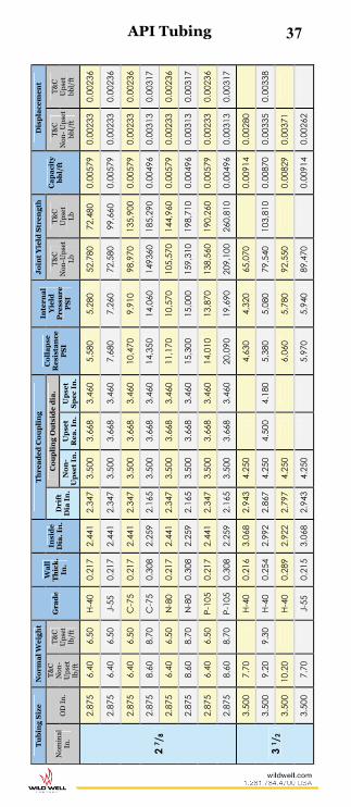
37
Tu
bin
g S
ize
N
orm
al
Wei
gh
t
Gra
de
W
all
T
hic
k.
In.
Insi
de
Dia
. In
.
Th
rea
ded
Co
up
lin
g
Co
lla
pse
R
esis
tan
ce
PS
I
Inte
rna
l Y
ield
P
ress
ure
P
SI
Jo
int
Yie
ld S
tre
ng
th
Ca
pa
city
b
bl/
ft
Dis
pla
cem
ent
Nom
inal
In
. O
D I
n.
T&
C
Non
-U
pset
lb
/ft
T&
C
Ups
et
lb/f
t
Dri
ft
Dia
In
.
Co
up
lin
g O
uts
ide
dia
. T
&C
N
on-U
pse
t L
b
T&
C
Ups
et
Lb
T&
C
Non
- U
pse
t bb
l/ft
T&
C
Ups
et
bbl/
ft
No
n-
Up
set
In.
Up
set
Re
a.
In.
Up
set
Sp
ec I
n.
2 7 /
8
2.87
5 6.
40
6.50
H-
40
0.21
7 2.
441
2.34
7 3.
500
3.66
8 3.
460
5,58
0 5,
280
52,7
80
72,4
80
0.00
579
0.00
233
0.00
236
2.87
5 6.
40
6.50
J-
55
0.21
7 2.
441
2.34
7 3.
500
3.66
8 3.
460
7,68
0 7,
260
72,5
80
99,6
60
0.00
579
0.00
233
0.00
236
2.87
5 6.
40
6.50
C
-75
0.21
7 2.
441
2.34
7 3.
500
3.66
8 3.
460
10,4
70
9,91
0 98
,970
13
5,90
0 0.
0057
9 0.
0023
3 0.
0023
6
2.87
5 8.
60
8.70
C
-75
0.30
8 2.
259
2.16
5 3.
500
3.66
8 3.
460
14,3
50
14,0
60
1493
60
185,
290
0.00
496
0.00
313
0.00
317
2.87
5 6.
40
6.50
N
-80
0.21
7 2.
441
2.34
7 3.
500
3.66
8 3.
460
11,1
70
10,5
70
105,
570
144,
960
0.00
579
0.00
233
0.00
236
2.87
5 8.
60
8.70
N
-80
0.30
8 2.
259
2.16
5 3.
500
3.66
8 3.
460
15,3
00
15,0
00
159,
310
198,
710
0.00
496
0.00
313
0.00
317
2.87
5 6.
40
6.50
P-
105
0.21
7 2.
441
2.34
7 3.
500
3.66
8 3.
460
14,0
10
13,8
70
138,
560
190,
260
0.00
579
0.00
233
0.00
236
2.87
5 8.
60
8.70
P-
105
0.30
8 2.
259
2.16
5 3.
500
3.66
8 3.
460
20,0
90
19,6
90
209,
100
260,
810
0.00
496
0.00
313
0.00
317
3 1 /
2
3.50
0 7.
70
H-
40
0.21
6 3.
068
2.94
3 4.
250
4,63
0 4,
320
65,0
70
0.
0091
4 0.
0028
0
3.50
0 9.
20
9.30
H-
40
0.25
4 2.
992
2.86
7 4.
250
4.50
0 4.
180
5,38
0 5,
080
79,5
40
103,
810
0.00
870
0.00
335
0.00
338
3.50
0 10
.20
H-
40
0.28
9 2.
922
2.79
7 4.
250
6,06
0 5,
780
92,5
50
0.
0082
9 0.
0037
1
3.50
0 7.
70
J-
55
0.21
5 3.
068
2.94
3 4.
250
5,97
0 5,
940
89,4
70
0.
0091
4 0.
0026
2
API Tubing

38
Tu
bin
g S
ize
N
orm
al
Wei
gh
t
Gra
de
W
all
T
hic
k.
In.
Insi
de
Dia
. In
.
Th
rea
ded
Co
up
lin
g
Co
lla
pse
R
esis
tan
ce
PS
I
Inte
rna
l Y
ield
P
ress
ure
P
SI
Jo
int
Yie
ld S
tre
ng
th
Ca
pa
city
b
bl/
ft
Dis
pla
cem
ent
Nom
inal
In
. O
D I
n.
T&
C
Non
-U
pset
lb
/ft
T&
C
Ups
et
lb/f
t
Dri
ft
Dia
In
.
Co
up
lin
g O
uts
ide
dia
. T
&C
N
on-U
pse
t L
b
T&
C
Ups
et
Lb
T&
C
Non
-Up
set
bbl/
ft
T&
C
Ups
et
bbl/
ft
No
n-
Up
set
In.
Up
set
Re
a.
In.
Up
set
Sp
ec I
n.
3 ½
3.50
0 9.
20
J-
55
0.25
4 2.
922
2.86
7 4.
250
7,40
0 6,
990
127,
250
0.
0082
9 0.
0037
1
3.50
0 10
.20
J-
55
0.28
9 2.
922
2.79
7 4.
250
8,33
0 7,
950
127,
250
0.
0082
9 0.
0037
1
3.50
0 7.
70
C
-75
0.21
6 3.
068
2.94
3 4.
250
7,54
0 8,
100
122,
010
0.
0091
4 0.
0028
0
3.50
0 10
.20
C
-75
0.28
9 2.
922
2.79
7 4.
250
11,3
60
10,8
40
173,
530
0.
0082
9 0.
0037
1
3.50
0 12
.70
12.9
5 C
-75
0.37
5 2.
750
2.62
5 4.
250
4.50
0 4.
180
14,3
50
14,0
60
230,
990
276,
120
0.00
735
0.00
462
0.00
471
3.50
0 7.
70
N
-80
0.21
6 3.
068
2.94
3 4.
250
7,87
0 8,
640
130,
140
0.
0091
4 0.
0028
0
3.50
0 10
.20
N
-80
0.28
9 2.
922
2.79
7 4.
250
12,1
20
11,5
60
185,
100
0.
0082
9 0.
0037
1
3.50
0 12
.70
12.9
5 N
-80
0.37
5 2.
750
2.62
5 4.
250
4.50
0 4.
180
15,3
10
15,0
00
246,
390
294,
530
0.00
735
0.00
462
0.00
471
3.50
0 9.
20
9.30
P-
105
0.25
4 2.
992
2.86
7 4.
250
4.50
0 4.
180
13,0
50
13,3
40
208,
800
271,
970
0.00
870
0.00
335
0.00
338
3.50
0 12
.70
12.9
5 P-
105
0.37
5 2.
750
2.62
5 4.
250
4.50
0 4.
180
20,0
90
19,6
90
323,
390
386,
570
0.00
735
0.00
462
0.00
471
API Tubing

39
Tu
bin
g S
ize
N
orm
al
Wei
gh
t
Gra
de
W
all
T
hic
k.
In.
Insi
de
Dia
. In
.
Th
rea
ded
Co
up
lin
g
Co
lla
pse
R
esis
tan
ce
PS
I
Inte
rna
l Y
ield
P
ress
ure
P
SI
Jo
int
Yie
ld S
tre
ng
th
Ca
pa
city
b
bl/
ft
Dis
pla
cem
ent
Nom
inal
In
. O
D I
n.
T&
C
Non
-U
pset
lb
/ft
T&
C
Ups
et
lb/f
t
Dri
ft
Dia
In
.
Co
up
lin
g O
uts
ide
dia
. T
&C
N
on-U
pse
t
Lb
T&
C
Ups
et
Lb
T&
C
Non
-Up
set
bbl/
ft
T&
C
Ups
et
bbl/
ft
No
n-
Up
set
In.
Up
set
Re
a.
In.
Up
set
Sp
ec I
n.
4
4.00
0 9.
50
H-
40
0.22
6 3.
548
3.42
3 4.
750
4,05
0 3,
960
72,0
00
0.
0122
3 0.
0034
6
4.00
0
11.0
0 H-
40
0.26
2 3.
476
3.35
1
5.00
0
4,90
0 4,
590
12
3,07
0 0.
0117
4
0.00
400
4.00
0 9.
50
J-
55
0.22
6 3.
548
3.42
3 4.
750
5,11
0 5,
440
99,0
10
0.
0122
3 0.
0034
6
4.00
0
11.0
0 J-
55
0.26
2 3.
476
3.35
1
5.00
0
6,59
0 6,
300
16
9,22
0 0.
0117
4
0.00
400
4.00
0 9.
50
C
-75
0.22
6 3.
548
3.42
3 4.
750
6,35
0
135,
010
0.
0122
3 0.
0034
6
4.00
0
11.0
0 C
-75
0.26
2 3.
476
3.35
1
5.00
0
8,41
0 8,
600
23
0,75
0 0.
0117
4
0.00
400
4.00
0 9.
50
N
-80
0.22
6 3.
548
3.42
3 4.
750
6,59
0 7,
910
144,
010
0.
0122
3 0.
0034
6
4.00
0
11.0
0 N
-80
0.26
2 3.
476
3.35
1
5.00
0
8,80
0 9,
170
24
6,14
0 0.
0117
4
0.00
400
4 1 /
2
4.50
0 12
.60
12.7
5 H-
40
0.27
1 3.
958
3.83
3 5.
200
5.56
3
4,49
0 4,
220
104,
360
144,
020
0.01
522
0.00
458
0.00
464
4.50
0 12
.60
12.7
5 J-
55
0.27
1 3.
958
3.83
3 5.
200
5.56
3
5,73
0 5,
800
143,
500
198,
030
0.01
522
0.00
458
0.00
464
4.50
0 12
.60
12.7
5 C
-75
0.27
1 3.
958
3.83
3 5.
200
5.56
3
7,20
0 7,
900
195,
680
270,
040
0.01
522
0.00
458
0.00
464
4.50
0 12
.60
12.7
5 N
-80
0.27
1 3.
958
3.83
3 5.
200
5.56
3
7,50
0 8,
430
208,
730
288,
040
0.01
522
0.00
458
0.00
464
API Tubing
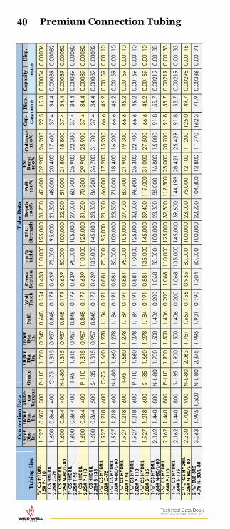
40
T
ub
ing
Siz
e
Co
nn
ect
ion
Da
ta
Tu
be
Da
ta
Ou
ter
Dia
. In
.
Inn
er
Dia
. In
.
Ma
ke
-u
p
To
rqu
e
Gra
de
O
ute
r D
ia.
In.
Inn
er
Dia
. In
. D
rift
W
all
T
hic
k
Cro
ss
Sec
tio
n
100
%
Yie
ld
Ult
. S
tre
ng
th
Dep
th
100
%
Pu
ll
100
%
PS
I B
urs
t 10
0%
C
oll
ap
se
100
%
Ca
p.
Dis
p.
Ca
pa
city
D
isp
.
Gal
s/10
00 f
t b
bls
/ft
¾" C
S HY
DRIL
1.
5# P
-110
1.
327
0.68
7 30
0 P-
110
1.05
0 0.
742
0.64
8 0.
154
0.43
3 11
0,00
0 12
5,00
0 31
,700
47
,600
32
,200
26
,200
22
.5
15.3
0.
0005
4 0.
0003
6 1"
CS
HYDR
IL
2.25
# C
-75
1.60
0 0.
864
400
C-7
5 1.
315
0.95
7 0.
848
0.17
9 0.
639
75,0
00
95,0
00
21,3
00
48,0
00
20,4
00
17,6
00
37.4
34
.4
0.00
089
0.00
082
1" C
S HY
DRIL
2.
25#
N-8
0/L-
80
1.60
0 0.
864
400
N-L
-80
1.31
5 0.
957
0.84
8 0.
179
0.63
9 80
,000
10
0,00
0 22
,600
51
,000
21
,800
18
,800
37
.4
34.4
0.
0008
9 0.
0008
2 1"
CS
HYDR
IL
2.25
# T-
95
1.60
0 0.
864
400
T-95
1.
315
0.95
7 0.
848
0.17
9 0.
639
95,0
00
105,
000
27,0
00
60,7
00
25,9
00
22,3
00
37.4
34
.4
0.00
089
0.00
082
1" C
S HY
DRIL
2.
25#
P-11
0 1.
600
0.86
4 40
0 P-
110
1.31
5 0.
957
0.84
8 0.
179
0.63
9 11
0,00
0 12
5,00
0 31
,200
70
,300
29
,900
25
,900
37
.4
34.4
0.
0008
9 0.
0008
2 1"
CS
HYDR
IL
2.25
# S-
135
1.60
0 0.
864
500
S-13
5 1.
315
0.95
7 0.
848
0.17
9 0.
639
135,
000
145,
000
38,3
00
86,2
00
36,7
00
31,7
00
37.4
34
.4
0.00
089
0.00
082
1-¼
" CS
HYDR
IL
3.02
# C
-75
1.92
7 1.
218
600
C-7
5 1.
660
1.27
8 1.
184
0.19
1 0.
881
75,0
00
95,0
00
21,8
00
66,0
00
17,2
00
15,2
00
66.6
46
.2
0.00
159
0.00
110
1-¼
" CS
HYDR
IL
3.02
# N
-80/
L-80
1.
927
1.21
8 60
0 N
-L-8
0 1.
660
1.27
8 1.
184
0.19
1 0.
881
80,0
00
100,
000
23,5
00
71,0
00
18,4
00
16,2
00
66.6
46
.2
0.00
159
0.00
110
1-¼
" CS
HYDR
IL
3.02
# T-
95
1.92
7 1.
218
600
T-95
1.
660
1.27
8 1.
184
0.19
1 0.
881
95,0
00
105,
000
27,7
00
83,7
00
21,9
00
19,3
00
66.6
46
.2
0.00
159
0.00
110
1-¼
" CS
HYDR
IL
3.02
# P-
110
1.92
7 1.
218
600
P-11
0 1.
660
1.27
8 1.
184
0.19
1 0.
881
110,
000
125,
000
32,0
00
96,6
00
25,3
00
22,4
00
66.6
46
.2
0.00
159
0.00
110
1-¼
" CS
HYDR
IL
3.02
# S-
135
1.92
7 1.
218
600
S-13
5 1.
660
1.27
8 1.
184
0.19
1 0.
881
135,
000
145,
000
39,4
00
119,
000
31,0
00
27,5
00
66.6
46
.2
0.00
159
0.00
110
1-½
" CS
HYDR
IL
3.64
# N
-80/
L-80
2.
162
1.44
0 80
0 N
-L-8
0 1.
900
1.50
0 1.
406
0.20
0 1.
068
80,0
00
100,
000
23,3
00
85,0
00
16,8
00
15,0
00
91.8
55
.7
0.00
219
0.00
133
1-½
" CS
HYDR
IL
3.64
# P-
110
2.16
2 1.
440
800
P-11
0 1.
900
1.50
0 1.
406
0.20
0 1.
068
110,
000
125,
000
32,3
00
117,
500
23,0
00
20,7
00
91.8
55
.7
0.00
219
0.00
133
1-½
" CS
HYDR
IL
3.64
# S-
135
2.16
2 1.
440
800
S-13
5 1.
900
1.50
0 1.
406
0.20
0 1.
068
135,
000
145,
000
39,6
00
144,
199
28,4
21
25,4
29
91.8
55
.7
0.00
219
0.00
133
2-1 /
16" C
S HY
DRIL
3.
25#
N-8
0/L-
80
2.33
0 1.
700
900
N-L
-80
2.06
3 1.
751
1.65
7 0.
156
0.93
5 80
,000
10
0,00
0 23
,000
75
,000
12
,100
11
,200
12
5.0
49.7
0.
0029
8 0.
0011
8 2-⅜
" EUE
8RD
4.
7# N
-80/
L-80
3.
063
1.99
5 1,
500
N-L
-80
2.37
5 1.
995
1.90
1 0.
190
1.30
4 80
,000
10
0,00
0 22
,200
10
4,30
0 12
,800
11
,770
16
2.3
71.9
0.
0038
6 0.
0017
1
Premium Connection Tubing

41
Tu
bin
g S
ize
Co
nn
ect
ion
Da
ta
Tu
be
Da
ta
Ou
ter
Dia
. In
.
Inn
er
Dia
. In
.
Ma
ke
-u
p
To
rqu
e
Gra
de
O
ute
r D
ia.
In.
Inn
er
Dia
. In
. D
rift
W
all
T
hic
k
Cro
ss
Sec
tio
n
100
%
Yie
ld
Ult
. S
tre
ng
th
Dep
th
100
%
Pu
ll
100
%
PS
I B
urs
t 10
0%
C
oll
ap
se
100
%
Ca
p.
Dis
p.
Ca
pa
city
D
isp
.
Gal
s/10
00 f
t b
bls
/ft
2-⅜
" PH-
6 HY
DRIL
5.
95#
N-8
0/L-
80
2.90
6 1.
805
2,20
0 N
-L-8
0 2.
375
1.86
7 1.
773
0.25
4 1.
692
80,0
00
100,
000
22,7
00
135,
000
17,1
00
15,3
00
142.
2 91
.0
0.00
339
0.00
217
2-⅜
" PH-
6 HY
DRIL
5.
95#
RY-8
5 2.
906
1.80
5 2,
200
RY-8
5 2.
375
1.86
7 1.
773
0.25
4 1.
692
85,0
00
100,
000
24,1
00
143,
800
18,2
00
16,2
40
142.
2 91
.0
0.00
339
0.00
217
2-⅜
" PH-
6 HY
DRIL
5.
95#
T-95
2.
906
1.80
5 2,
200
T-95
2.
375
1.86
7 1.
773
0.25
4 1.
692
95,0
00
110,
000
27,0
00
160,
740
19,6
65
17,5
95
142.
2 91
.0
0.00
339
0.00
217
2-⅜
" PH-
6 HY
DRIL
5.
95#
P-11
0 2.
906
1.80
5 2,
700
P-11
0 2.
375
1.86
7 1.
773
0.25
4 1.
692
105,
000
120,
000
29,9
00
178,
000
22,5
00
20,0
60
142.
2 91
.0
0.00
339
0.00
217
2-⅞
" EUE
8RD
6.
5# N
-80/
L-80
3.
668
2.44
1 2,
300
N-L
-80
2.87
5 2.
441
2.34
7 0.
217
1.81
2 80
,000
10
0,00
0 22
,300
14
5,00
0 12
,100
11
,160
24
3.0
99.5
0.
0057
9 0.
0023
7 2-⅞
" PH-
6 HY
DRIL
8.
7# N
-80/
L-80
3.
500
2.20
0 3,
000
N-L
-80
2.87
5 2.
259
2.16
5 0.
308
2.48
4 80
,000
10
0,00
0 22
,800
19
8,70
0 17
,140
15
,300
20
8.1
133.
1 0.
0049
5 0.
0031
7 2-⅞
" PH-
6 HY
DRIL
7.
9# N
-80/
L-80
3.
437
2.26
5 3,
000
N-L
-80
2.87
5 2.
323
2.22
9 0.
276
2.25
4 80
,000
10
0,00
0 22
,800
18
0,00
0 15
,300
13
,900
22
0.0
120.
9 0.
0052
4 0.
0028
8 2-⅞
" PH-
6 HY
DRIL
7.
9# T-
95
3.43
7 2.
265
3,20
0 T-
95
2.87
5 2.
323
2.22
9 0.
276
2.25
4 95
,000
11
0,00
0 27
,098
21
4,08
2 18
,000
16
,000
22
0.0
120.
9 0.
0052
4 0.
0028
8 2-⅞
" PH-
6 HY
DRIL
7.
9# P
-110
3.
437
2.26
5 3,
500
P-11
0 2.
875
2.32
3 2.
229
0.27
6 2.
254
105,
000
120,
000
29,9
00
236,
000
20,1
00
18,2
00
220.
0 12
0.9
0.00
524
0.00
288
3-½
" EUE
8RD
9.
3# N
-80/
L-80
4.
500
2.99
2 2,
400-
3,20
0 N
-L-8
0 3.
500
2.99
2 2.
867
0.25
4 2.
590
80,0
00
100,
000
22,2
00
207,
200
11,6
00
10,7
00
365.
2 13
4.5
0.00
870
0.00
320
3-½
" EUE
8RD
9.
3# P
-110
4.
500
2.99
2 3,
000-
4,00
0 P-
110
3.50
0 2.
992
2.86
7 0.
254
2.59
0 11
0,00
0 12
5,00
0 30
,600
28
4,90
0 15
,900
14
,800
36
5.2
134.
5 0.
0087
0 0.
0032
0 3-
½" P
H-6
HYDR
IL
12.9
5# N
-80/
L-80
4.
312
2.68
7 5,
500
N-L
-80
3.50
0 2.
750
2.62
5 0.
375
3.68
2 80
,000
10
0,00
0 22
,700
29
4,50
0 17
,100
15
,310
30
8.4
198.
1 0.
0073
4 0.
0047
2 3-
½" P
H-6
HYDR
IL
12.9
5# T-
95
4.31
3 2.
687
6,00
0 T-
95
3.50
0 2.
750
2.62
5 0.
375
3.68
2 95
,000
10
5,00
0 27
,000
38
6,60
0 20
,300
18
,100
30
8.4
198.
1 0.
0073
4 0.
0047
2 3-
½" P
H-6
HYDR
IL
12.9
5# P
-110
4.
312
2.68
7 7,
000
P-11
0 3.
500
2.75
0 2.
625
0.37
5 3.
682
105,
000
120,
000
29,8
00
386,
600
22,5
00
20,0
90
308.
4 19
8.1
0.00
734
0.00
472
4-½
" PH-
6 HY
DRIL
15
.50#
P-1
10
5.12
5 3.
765
8,50
0 P-
110
4.50
0 3.
826
3.70
1 0.
337
4.40
7 11
0,00
0 12
5,00
0 31
,300
48
5,00
0 16
,480
14
,340
59
8.0
229.
2 0.
0142
4 0.
0054
6
Premium Connection Tubing
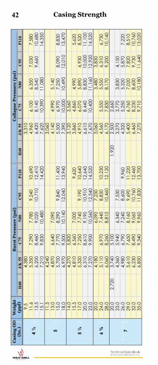
42 Ca
sin
g O
D
(In
.)
We
igh
t (p
pf)
B
urs
t P
ress
ure
(p
si)
Co
lla
pse
Pre
ssu
re (
psi
) H
40
J/K
55
C75
N
80
C95
P
110
H40
J/
K 5
5 C
75
N80
C
95
P11
0
4 ½
9.
5
4,38
0
3,31
0
11
.6
5,
350
7,29
0 7,
780
9,24
0 10
,690
4,96
0 6,
100
6,35
0 7,
030
7,58
0 13
.5
6,
200
8,46
0 9,
020
10,7
10
12,4
10
6,
420
8,14
0 8,
540
9,66
0 10
,680
15
.1
7,
210
9,83
0 10
,480
14,4
20
7,
620
10,3
90
11,0
80
14
,350
5 11
.5
4,
240
3,
060
13.0
4,87
0 6,
640
7,09
0
4,14
0 4,
990
5,14
0
15
.0
5,
700
7,77
0 8,
290
9,84
0 11
,400
5,50
0 6,
970
7,25
0 8,
090
8,83
0 18
.0
6,
970
9,50
0 10
,140
12
,040
13
,940
7,39
0 10
,000
10
,490
12
,010
13
,470
5 ½
14.0
4,27
0 5,
820
3,12
0 3,
560
15
.5
4,
810
6,56
0 7,
000
9,
620
3,
860
4,86
0 4,
990
5,
620
17.0
5,32
0 7,
250
7,74
0 9,
190
10,6
40
4,
910
6,07
0 5,
890
6,93
0 8,
520
20.0
6,31
0 8,
610
9,19
0 10
,910
12
,640
6,61
0 8,
440
8,83
0 10
,000
11
,100
23
.0
7,
270
9,90
0 10
,560
12
,540
14
,520
7,67
0 10
,400
11
,160
12
,920
14
,520
6 ⅝
20
.0
4,
180
6,
090
7,23
0
3,
060
3,
480
3,83
0
24.0
5,11
0 6,
970
7,44
0 8,
830
10,2
30
4,
560
5,55
0 5,
550
6,31
0 6,
730
28.0
6,06
0 8,
260
8,81
0 10
,460
12
,120
6,17
0 7,
830
8,17
0 9,
200
10,1
40
7
20.0
2,
720
3,74
0 5,
100
1,
920
2,50
0 2,
660
23
.0
4,
360
5,94
0 6,
340
7,53
0
3,
270
3,77
0 3,
830
4,15
0
26.0
4,98
0 6,
790
7,24
0 8,
600
9,96
0
4,32
0 5,
250
5,32
0 5,
870
7,22
0 29
.0
5,
610
7,65
0 8,
160
9,69
0 11
,220
5,40
0 6,
760
7,02
0 7,
820
8,51
0 32
.0
6,
230
8,49
0 9,
060
10,7
60
12,4
60
6,
460
8,23
0 8,
600
9,73
0 10
,760
35
.0
6,
850
9,34
0 9,
960
11,8
30
13,7
00
7,
270
9,71
0 10
,180
11
,640
13
,020
Casing Strength

43 C
asi
ng
OD
(I
n.)
W
eig
ht
(pp
f)
Bu
rst
Pre
ssu
re (
psi
) C
oll
ap
se P
ress
ure
(p
si)
H40
J/
K 5
5 C
75
N80
C
95
P11
0 H
40
J/K
55
C75
N
80
C95
P
110
7 ⅝
26
.4
4,
140
5,65
0 6,
020
7,15
0 8,
280
3,
010
3,28
0 3,
930
3,71
0 3,
900
29.7
6,
450
6,89
0 8,
180
9,47
0
4,
670
4,79
0 5,
120
6,18
0 33
.7
5,
430
7,40
0 7,
900
8,18
0 10
,860
5,09
0 6,
320
6,56
0 7,
260
7,87
0 39
.0
8,61
0 9,
180
9,38
0 12
,620
8,
430
8,82
0 9,
980
11,0
60
8 ⅝
24
.0
2,
950
95
0
32
.0
2,86
0 3,
930
5,36
0 5,
710
7,86
0
2,21
0 2,
530
2,95
0 3,
050
3,
430
36.0
4,46
0 6,
090
6,49
0 7,
710
8,93
0
3,45
0 4,
020
4,47
0 4,
360
4,70
0 40
.0
5,
020
6,85
0 7,
300
8,67
0 10
,040
4,40
0 5,
350
5,52
0 6,
010
7,42
0
9 ⅝
36.0
2,
560
3,52
0 4,
800
5,12
0
7,04
0 1,
710
2,22
0 2,
320
2,37
0
2,47
0 40
.0
3,
950
5,39
0 5,
750
6,82
0 7,
900
2,
570
2,98
0 3,
530
3,33
0 3,
480
43.5
4,35
0 5,
930
6,33
0 7,
510
8,70
0
3,25
0 3,
750
3,81
0 4,
130
4,76
0 47
.0
4,
720
6,44
0 6,
870
8,15
0 9,
440
3,
880
4,63
0 4,
760
5,08
0 5,
310
53.5
7,
430
7,93
0 9,
410
10,9
00
6,38
0 6,
620
7,33
0 7,
930
10 ¾
40.5
2,
280
3,13
0 4,
270
1,
420
1,73
0 1,
720
45
.5
3,
580
4,88
0 5,
210
7,16
0
2,
090
2,41
0 2,
480
2,
610
51.0
4,03
0 5,
490
5,86
0 6,
960
8,06
0
2,70
0 3,
100
3,75
0 3,
490
3,75
0 55
.5
4,
430
6,04
0 6,
450
7,66
0 8,
860
3,
320
3,95
0 4,
020
4,30
0 4,
630
60.7
4,88
0 6,
650
7,10
0 8,
436
9,76
0
4,16
0 5,
020
5,16
0 5,
566
5,86
0 65
.7
5,
330
7,26
0 7,
750
9,20
0 10
,650
4,92
0 6,
080
6,30
0 6,
950
7,49
0 71
.1
10,0
50
11,6
40
8,47
0 9,
280
11 ¾
47
.0
3,
070
4,19
0
1,
630
1,62
0
54.0
3,56
0 4,
860
2,07
0 2,
380
60
.0
4,
010
5,46
0 5,
830
6,92
0 8,
010
2,
660
3,07
0 3,
680
3,44
0 3,
610
Casing Strength

44 C
asi
ng
OD
(I
n.)
W
eig
ht
(pp
f)
Bu
rst
Pre
ssu
re (
psi
) C
oll
ap
se P
ress
ure
(p
si)
H40
J/
K 5
5 C
75
N80
C
95
P11
0 H
40
J/K
55
C75
N
80
C95
P
110
13 ⅜
48.0
1,
730
77
0
54.5
2,73
0 3,
980
5,47
0
1,14
0
61
.0
3,
090
4,22
0 4,
500
1,
540
1,66
0 1,
670
68.0
3,45
0 4,
710
5,02
0 5,
970
1,95
0 2,
220
2,27
0 2,
330
72
.0
3,
700
5,04
0 5,
380
6,39
0 7,
400
2,
230
2,59
0 2,
880
2,82
0 2,
880
77.0
5,
400
5,76
0
2,
990
3,10
0
85
.0
5,97
0 6,
360
8,75
0
3,81
0 3,
870
4,49
0
16
65.0
1,
640
67
0
75.0
2,63
0
1,01
0
84
.0
2,
980
1,
410
109.
0
3,95
0
7,89
0
2,56
0
3,47
0
18 ⅝
87
.5
1,53
0 2,
110
520
520
106.
0
2,74
0
1,14
0
20
94.0
1,
530
2,11
0
52
0 52
0
10
6.5
2,
410
77
0
13
3.0
3,
060
1,
500
24
156.
0 X-
42
1,91
0
86
0
26
202.
0 X-
42
2,12
0
1,
100
30
31
0.0
X-42
2,
450
1,48
0
36
374.
0 X-
42
2,04
0
1,
010
Casing Strength
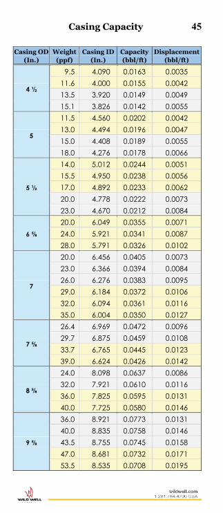
Casing Capacity 45
Casing OD (In.)
Weight (ppf)
Casing ID (In.)
Capacity (bbl/ft)
Displacement (bbl/ft)
4 ½
9.5 4.090 0.0163 0.0035 11.6 4.000 0.0155 0.0042 13.5 3.920 0.0149 0.0049 15.1 3.826 0.0142 0.0055
5
11.5 4.560 0.0202 0.0042 13.0 4.494 0.0196 0.0047 15.0 4.408 0.0189 0.0055 18.0 4.276 0.0178 0.0066
5 ½
14.0 5.012 0.0244 0.0051 15.5 4.950 0.0238 0.0056 17.0 4.892 0.0233 0.0062 20.0 4.778 0.0222 0.0073 23.0 4.670 0.0212 0.0084
6 ⅝
20.0 6.049 0.0355 0.0071 24.0 5.921 0.0341 0.0087 28.0 5.791 0.0326 0.0102
7
20.0 6.456 0.0405 0.0073 23.0 6.366 0.0394 0.0084 26.0 6.276 0.0383 0.0095 29.0 6.184 0.0372 0.0106 32.0 6.094 0.0361 0.0116 35.0 6.004 0.0350 0.0127
7 ⅝
26.4 6.969 0.0472 0.0096 29.7 6.875 0.0459 0.0108 33.7 6.765 0.0445 0.0123 39.0 6.624 0.0426 0.0142
8 ⅝
24.0 8.098 0.0637 0.0086 32.0 7.921 0.0610 0.0116 36.0 7.825 0.0595 0.0131 40.0 7.725 0.0580 0.0146
9 ⅝
36.0 8.921 0.0773 0.0131 40.0 8.835 0.0758 0.0146 43.5 8.755 0.0745 0.0158 47.0 8.681 0.0732 0.0171 53.5 8.535 0.0708 0.0195

46 Casing Capacity
Casing OD (In.)
Weight (ppf)
Casing ID (In.)
Capacity (bbl/ft)
Displacement (bbl/ft)
10 ¾
40.5 10.050 0.0981 0.0147 45.5 9.950 0.0962 0.0166 51.0 9.850 0.0943 0.0186 55.5 9.760 0.0925 0.0202 60.7 9.660 0.0907 0.0216 65.7 9.560 0.0888 0.0235 71.1 9.450 0.0868 0.0255 76.0 9.350 0.0849 0.0273 81.0 9.250 0.0831 0.0291
11 ¾ 47.0 11.000 0.1175 0.0171 54.0 10.880 0.1150 0.0197 60.0 10.772 0.1127 0.0218
13 ⅜
48.0 12.715 0.1571 0.0175 54.5 12.615 0.1546 0.0198 61.0 12.515 0.1522 0.0219 68.0 12.415 0.1497 0.0247 72.0 12.347 0.1481 0.0262 77.0 12.275 0.1464 0.0274 85.0 12.159 0.1436 0.0302
16
65.0 15.250 0.2259 0.0237 75.0 15.124 0.2222 0.0273 84.0 15.010 0.2189 0.0306
109.0 14.688 0.2096 0.0391 118.0 14.570 0.2062 0.0425
18 ⅝ 87.5 17.755 0.3062 0.0307
109.0 17.491 0.2972 0.0398 122.0 17.385 0.2936 0.0434
20 94.0 19.124 0.3553 0.0342
106.5 19.000 0.3507 0.0388 133.0 18.730 0.3408 0.0484
24 x 5/8" tin 156.0 22.750 0.5028 0.0568 30 x 1" tin 310.0 28.000 0.7616 0.1127 36 x 1" tin 374.0 34.000 1.1230 0.1360 48 x 1" tin 502.0 46.000 2.0556 0.1826
Note: To find casing weight for other wall thicknesses:
Weight of Casinglb/ft = 10.68 x (Odin – tin) x tin
Where: tin = Wall thickness (inches)
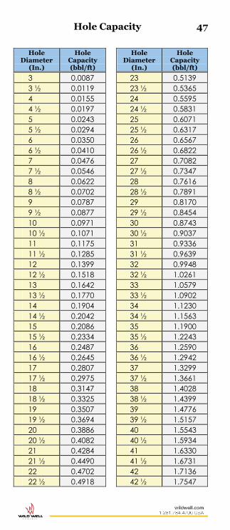
Hole Capacity 47
Hole Diameter
(In.)
Hole Capacity (bbl/ft)
Hole Diameter
(In.)
Hole Capacity (bbl/ft)
3 0.0087 23 0.5139 3 ½ 0.0119 23 ½ 0.5365 4 0.0155 24 0.5595 4 ½ 0.0197 24 ½ 0.5831 5 0.0243 25 0.6071 5 ½ 0.0294 25 ½ 0.6317 6 0.0350 26 0.6567 6 ½ 0.0410 26 ½ 0.6822 7 0.0476 27 0.7082 7 ½ 0.0546 27 ½ 0.7347 8 0.0622 28 0.7616 8 ½ 0.0702 28 ½ 0.7891 9 0.0787 29 0.8170 9 ½ 0.0877 29 ½ 0.8454 10 0.0971 30 0.8743 10 ½ 0.1071 30 ½ 0.9037 11 0.1175 31 0.9336 11 ½ 0.1285 31 ½ 0.9639 12 0.1399 32 0.9948 12 ½ 0.1518 32 ½ 1.0261 13 0.1642 33 1.0579 13 ½ 0.1770 33 ½ 1.0902 14 0.1904 34 1.1230 14 ½ 0.2042 34 ½ 1.1563 15 0.2086 35 1.1900 15 ½ 0.2334 35 ½ 1.2243 16 0.2487 36 1.2590 16 ½ 0.2645 36 ½ 1.2942 17 0.2807 37 1.3299 17 ½ 0.2975 37 ½ 1.3661 18 0.3147 38 1.4028 18 ½ 0.3325 38 ½ 1.4399 19 0.3507 39 1.4776 19 ½ 0.3694 39 ½ 1.5157 20 0.3886 40 1.5543 20 ½ 0.4082 40 ½ 1.5934 21 0.4284 41 1.6330 21 ½ 0.4490 41 ½ 1.6731 22 0.4702 42 1.7136 22 ½ 0.4918 42 ½ 1.7547

48 L
ine
r D
iam
ete
r S
TR
OK
E L
EN
GT
H (
INC
HE
S)
Un
its
2 2
½
3 4
5 6
7 7
½
8 8
½
9 9
½
10
11
12
1"
0.00
05
0.00
06
0.00
07
0.00
10
0.00
12
0.00
15
0.00
17
0.00
18
0.00
19
0.00
21
0.00
22
0.00
23
0.00
24
0.00
27
0.00
29
BBLS
/STK
0.
0204
0.
0255
0.
0306
0.
0408
0.
0510
0.
0612
0.
0714
0.
0765
0.
0816
0.
0868
0.
0919
0.
0970
0.
1021
0.
1123
0.
1225
G
al/S
TK
1 ⅜
" 0.
0009
0.
0011
0.
0014
0.
0018
0.
0023
0.
0028
0.
0032
0.
0034
0.
0037
0.
0039
0.
0041
0.
0044
0.
0046
0.
0051
0.
0055
BB
LS/S
TK
0.03
86
0.04
82
0.05
79
0.07
72
0.09
65
0.11
58
0.13
51
0.14
47
0.15
44
0.16
40
0.17
37
0.18
33
0.19
30
0.21
23
0.23
15
Gal
/STK
1 ½
" 0.
0011
0.
0014
0.
0016
0.
0022
0.
0027
0.
0033
0.
0038
0.
0041
0.
0044
0.
0046
0.
0049
0.
0052
0.
0055
0.
0060
0.
0066
BB
LS/S
TK
0.04
59
0.05
74
0.06
89
0.09
19
0.11
48
0.13
78
0.16
07
0.17
22
0.18
37
0.19
52
0.20
67
0.21
82
0.22
96
0.25
26
0.27
56
Gal
/STK
1 ⅝
" 0.
0013
0.
0016
0.
0019
0.
0026
0.
0032
0.
0039
0.
0045
0.
0048
0.
0051
0.
0055
0.
0058
0.
0061
0.
0064
0.
0071
0.
0077
BB
LS/S
TK
0.05
39
0.06
74
0.08
09
0.10
78
0.13
48
0.16
17
0.18
87
0.20
21
0.21
56
0.22
91
0.24
26
0.25
60
0.26
95
0.29
65
0.32
34
Gal
/STK
1 ¾
" 0.
0015
0.
0019
0.
0022
0.
0030
0.
0037
0.
0045
0.
0052
0.
0056
0.
0060
0.
0063
0.
0067
0.
0071
0.
0074
0.
0082
0.
0089
BB
LS/S
TK
0.06
25
0.07
81
0.09
38
0.12
50
0.15
63
0.18
75
0.21
88
0.23
44
0.25
00
0.26
57
0.28
13
0.29
69
0.31
26
0.34
38
0.37
51
Gal
/STK
2"
0.00
19
0.00
24
0.00
29
0.00
39
0.00
49
0.00
58
0.00
68
0.00
73
0.00
78
0.00
83
0.00
87
0.00
92
0.00
97
0.01
07
0.01
17
BBLS
/STK
0.
0816
0.
1021
0.
1225
0.
1633
0.
2041
0.
2449
0.
2858
0.
3062
0.
3266
0.
3470
0.
3674
0.
3878
0.
4082
0.
4491
0.
4899
G
al/S
TK
2 ¼
" 0.
0025
0.
0031
0.
0037
0.
0049
0.
0062
0.
0074
0.
0086
0.
0092
0.
0098
0.
0105
0.
0111
0.
0117
0.
0123
0.
0135
0.
0148
BB
LS/S
TK
0.10
33
0.12
92
0.15
50
0.20
67
0.25
83
0.31
00
0.36
17
0.38
75
0.41
33
0.43
92
0.46
50
0.49
08
0.51
67
0.56
83
0.62
00
Gal
/STK
2 ½
" 0.
0030
0.
0038
0.
0046
0.
0061
0.
0076
0.
0091
0.
0106
0.
0114
0.
0122
0.
0129
0.
0137
0.
0144
0.
0152
0.
0167
0.
0182
BB
LS/S
TK
0.12
76
0.15
95
0.19
14
0.25
52
0.31
89
0.38
27
0.44
65
0.47
84
0.51
03
0.54
22
0.57
41
0.60
60
0.63
79
0.70
17
0.76
55
Gal
/STK
2 ¾
" 0.
0037
0.
0046
0.
0055
0.
0074
0.
0092
0.
0110
0.
0129
0.
0138
0.
0147
0.
0156
0.
0165
0.
0175
0.
0184
0.
0202
0.
0221
BB
LS/S
TK
0.15
44
0.19
30
0.23
15
0.30
87
0.38
59
0.46
31
0.54
03
0.57
89
0.61
75
0.65
61
0.69
46
0.73
32
0.77
18
0.84
90
0.92
62
Gal
/STK
3"
0.00
44
0.00
55
0.00
66
0.00
87
0.01
09
0.01
31
0.01
53
0.01
64
0.01
75
0.01
86
0.01
97
0.02
08
0.02
19
0.02
41
0.02
62
BBLS
/STK
0.
1837
0.
2296
0.
2756
0.
3674
0.
4593
0.
5511
0.
6430
0.
6889
0.
7348
0.
7808
0.
8267
0.
8726
0.
9185
1.
0104
1.
1022
G
al/S
TK
3 ¼
" 0.
0051
0.
0064
0.
0077
0.
0103
0.
0128
0.
0154
0.
0180
0.
0193
0.
0205
0.
0218
0.
0231
0.
0244
0.
0257
0.
0282
0.
0308
BB
LS/S
TK
0.21
56
0.26
95
0.32
34
0.43
12
0.53
90
0.64
68
0.75
46
0.80
85
0.86
24
0.91
63
0.97
02
1.02
41
1.07
80
1.18
58
1.29
36
Gal
/STK
3 ½
" 0.
0060
0.
0074
0.
0089
0.
0119
0.
0149
0.
0179
0.
0208
0.
0223
0.
0238
0.
0253
0.
0268
0.
0283
0.
0298
0.
0327
0.
0357
BB
LS/S
TK
0.25
00
0.31
26
0.37
51
0.50
01
0.62
51
0.75
01
0.87
52
0.93
77
1.00
02
1.06
27
1.12
52
1.18
77
1.25
02
1.37
53
1.50
03
Gal
/STK
3 ¾
" 0.
0068
0.
0085
0.
0103
0.
0137
0.
0171
0.
0205
0.
0239
0.
0256
0.
0273
0.
0290
0.
0308
0.
0325
0.
0342
0.
0376
0.
0410
BB
LS/S
TK
0.28
70
0.35
88
0.43
06
0.57
41
0.71
76
0.86
11
1.00
47
1.07
64
1.14
82
1.21
99
1.29
17
1.36
35
1.43
52
1.57
87
1.72
23
Gal
/STK
Triplex Pumps 100% Efficiency

49 L
ine
r D
iam
ete
r S
TR
OK
E L
EN
GT
H (
INC
HE
S)
Un
its
2 2
½
3 4
5 6
7 7
½
8 8
½
9 9
½
10
11
12
4"
0.00
78
0.00
97
0.01
17
0.01
56
0.01
94
0.02
33
0.02
72
0.02
92
0.03
11
0.03
30
0.03
50
0.03
69
0.03
89
0.04
28
0.04
67
BBLS
/STK
0.
3266
0.
4082
0.
4899
0.
6532
0.
8165
0.
9798
1.
1431
1.
2247
1.
3064
1.
3880
1.
4697
1.
5513
1.
6330
1.
7963
1.
9596
G
al/S
TK
4 ¼
" 0.
0088
0.
0110
0.
0132
0.
0176
0.
0219
0.
0263
0.
0307
0.
0329
0.
0351
0.
0373
0.
0395
0.
0417
0.
0439
0.
0483
0.
0527
BB
LS/S
TK
0.36
87
0.46
09
0.55
30
0.73
74
0.92
17
1.10
61
1.29
07
1.38
26
1.47
48
1.56
69
1.65
91
1.75
13
1.84
35
2.02
78
2.21
22
Gal
/STK
4 ½
" 0.
0098
0.
0123
0.
0148
0.
0197
0.
0246
0.
0295
0.
0344
0.
0369
0.
0394
0.
0418
0.
0443
0.
0467
0.
0492
0.
0541
0.
0590
BB
LS/S
TK
0.41
33
0.51
67
0.62
00
0.82
67
1.03
34
1.24
00
1.44
67
1.55
00
1.65
34
1.75
67
1.86
00
1.96
34
2.06
67
2.27
34
2.48
01
Gal
/STK
4 ¾
" 0.
0110
0.
0137
0.
0164
0.
0219
0.
0274
0.
0329
0.
0384
0.
0411
0.
0439
0.
0466
0.
0493
0.
0521
0.
0548
0.
0603
0.
0658
BB
LS/S
TK
0.46
05
0.57
57
0.69
08
0.92
11
1.15
14
1.38
16
1.61
19
1.72
70
1.84
22
1.95
73
2.07
25
2.18
76
2.30
27
2.53
30
2.76
33
Gal
/STK
5"
0.01
22
0.01
52
0.01
82
0.02
43
0.03
04
0.03
65
0.04
25
0.04
56
0.04
86
0.05
16
0.05
47
0.05
77
0.06
08
0.06
68
0.07
29
BBLS
/STK
0.
5103
0.
6379
0.
7655
1.
0206
1.
2758
1.
5309
1.
7861
1.
9136
2.
0412
2.
1688
2.
2964
2.
4239
2.
5515
2.
8067
3.
0618
G
al/S
TK
5 ¼
" 0.
0134
0.
0167
0.
0201
0.
0268
0.
0335
0.
0402
0.
0469
0.
0502
0.
0536
0.
0569
0.
0603
0.
0636
0.
0670
0.
0737
0.
0804
BB
LS/S
TK
0.56
26
0.70
33
0.84
39
1.12
52
1.40
65
1.68
78
1.96
91
2.10
98
2.25
04
2.39
11
2.53
17
2.67
24
2.81
30
3.09
43
3.37
56
Gal
/STK
5 ½
" 0.
0147
0.
0184
0.
0221
0.
0294
0.
0368
0.
0441
0.
0515
0.
0551
0.
0588
0.
0625
0.
0662
0.
0698
0.
0735
0.
0809
0.
0882
BB
LS/S
TK
0.61
75
0.77
18
0.92
62
1.23
49
1.54
37
1.85
24
2.16
11
2.31
55
2.46
99
2.62
42
2.77
86
2.93
29
3.08
73
3.39
60
3.70
48
Gal
/STK
5 ¾
" 0.
0161
0.
0201
0.
0241
0.
0321
0.
0402
0.
0482
0.
0562
0.
0603
0.
0643
0.
0683
0.
0723
0.
0763
0.
0803
0.
0884
0.
0964
BB
LS/S
TK
0.67
49
0.84
36
1.01
23
1.34
97
1.68
72
2.02
46
2.36
21
2.53
08
2.69
95
2.86
82
3.03
69
3.20
56
3.37
44
3.71
18
4.04
92
Gal
/STK
6"
0.01
75
0.02
19
0.02
62
0.03
50
0.04
37
0.05
25
0.06
12
0.06
56
0.07
00
0.07
44
0.07
87
0.08
31
0.08
75
0.09
62
0.10
50
BBLS
/STK
0.
7348
0.
9185
1.
1022
1.
4697
1.
8372
2.
2045
2.
5719
2.
7556
2.
9393
3.
1230
3.
3067
3.
4905
3.
6742
4.
0416
4.
4090
G
al/S
TK
6 ¼
" 0.
0190
0.
0237
0.
0285
0.
0380
0.
0475
0.
0570
0.
0664
0.
0712
0.
0759
0.
0807
0.
0854
0.
0902
0.
0949
0.
1044
0.
1139
BB
LS/S
TK
0.79
73
0.99
67
1.19
60
1.59
47
1.99
34
2.39
20
2.79
07
2.99
00
3.18
94
3.38
87
3.58
80
3.78
74
3.98
67
4.38
54
4.78
41
Gal
/STK
6 ½
" 0.
0205
0.
0257
0.
0308
0.
0411
0.
0513
0.
0616
0.
0719
0.
0770
0.
0821
0.
0873
0.
0924
0.
0975
0.
1027
0.
1129
0.
1232
BB
LS/S
TK
0.86
24
1.07
80
1.29
36
1.72
48
2.15
60
2.58
72
3.01
84
3.23
40
3.44
96
3.66
52
3.88
08
4.09
64
4.31
20
4.74
32
5.17
44
Gal
/STK
6 ¾
" 0.
0221
0.
0277
0.
0332
0.
0443
0.
0554
0.
0664
0.
0775
0.
0830
0.
0886
0.
0941
0.
0996
0.
1052
0.
1107
0.
1218
0.
1329
BB
LS/S
TK
0.93
00
1.16
25
1.39
50
1.86
00
2.32
51
2.79
01
3.25
51
3.48
76
3.72
01
3.95
26
4.18
51
4.41
76
4.65
01
5.11
51
5.58
01
Gal
/STK
7"
0.02
38
0.02
98
0.03
57
0.04
76
0.05
95
0.07
14
0.08
33
0.08
93
0.09
53
0.10
12
0.10
72
0.11
31
0.11
91
0.13
10
0.14
29
BBLS
/STK
1.
0002
1.
2502
1.
5003
2.
0004
2.
5005
3.
0006
3.
5007
3.
7507
4.
008
4.25
08
4.50
08
4.75
09
5.00
09
5.50
10
6.00
11
Gal
/STK
Triplex Pumps 100% Efficiency

50 In
itia
l M
ud
Wt
(pp
g)
DE
SIR
ED
MU
D W
EIG
HT
(P
PG
)
9.5
10.0
10
.5
11.0
11
.5
12.0
12
.5
13.0
13
.5
14.0
14
.5
15.0
15
.5
16.0
16
.5
17.0
17
.5
18.0
9.0
29
59
90
123
156
192
229
268
308
350
395
442
490
542
596
653
714
778
9.5
29
60
92
12
5 16
0 19
6 23
4 27
3 31
5 35
9 40
5 45
2 50
3 55
7 61
2 67
2 73
5 10
.0
43
30
61
93
12
8 16
4 20
1 23
9 28
0 32
3 36
8 41
4 46
4 51
6 57
1 63
0 69
1 10
.5
85
30
31
62
96
13
1 16
7 20
5 24
5 28
7 33
1 37
6 42
6 47
9 53
1 58
8 64
8 11
.0
128
60
23
31
64
98
13
4 17
1 21
0 25
1 29
4 33
9 38
7 43
7 49
0 54
6 60
5 11
.5
171
90
46
19
32
66
10
1 13
7 17
5 21
5 25
8 30
1 34
8 39
7 44
9 50
4 56
2 12
.0
214
120
69
37
16
33
67
10
3 14
0 17
9 22
1 26
3 31
0 35
7 40
8 46
2 51
8 12
.5
256
150
92
56
32
14
34
68
10
5 14
4 18
4 22
6 27
1 31
8 36
7 42
0 47
5 13
.0
299
180
115
75
48
27
12
34
70
10
8 14
7 18
8 23
2 27
8 32
7 37
8 43
2 13
.5
342
210
138
94
63
41
24
11
35
72
11
1 15
0 19
4 23
8 28
6 33
6 38
9 14
.0
385
240
161
112
76
54
36
21
10
36
74
11
3 15
5 19
9 24
5 29
4 34
5 14
.5
427
270
185
131
95
68
48
32
19
9
37
75
116
159
204
252
302
15.0
47
0 30
0 20
8 15
0 11
0 82
60
43
29
18
8
37
77
11
9 16
3 21
0 25
9 15
.5
513
330
231
169
126
95
72
54
39
26
16
8
39
79
122
168
216
16.0
55
6 36
0 25
4 18
7 14
2 10
9 84
64
48
35
24
15
7
40
81
12
6 17
2 16
.5
598
390
277
206
158
123
96
75
58
44
32
23
14
7
41
84
129
17.0
64
1 42
0 30
0 22
5 17
4 13
6 10
8 86
68
53
40
30
21
13
6
42
86
17
.5
684
450
323
244
189
150
120
96
77
62
49
38
28
20
12
6
43
18.0
72
6 48
0 34
6 26
2 20
5 16
3 13
2 10
7 87
71
57
45
35
26
18
12
5
Di
lutio
n or
Cut
Bac
k: T
he g
ray
sect
ion
of th
e ch
art s
how
s the
num
ber o
f bar
rels
of
wat
er w
hich
mus
t be
add
ed to
100
bbl
s of m
ud to
pro
duc
e th
e d
esire
d w
eigh
t re
duc
tion.
Mud
Wei
ght I
ncre
ase:
The
yel
low
sect
ion
of th
e ch
art i
ndic
ate
s the
num
ber
of 1
00 lb
sack
s of b
arit
e w
hich
mus
t be
ad
ded
to 1
00 b
bls o
f mud
to
prod
uce
des
ired
wei
ght i
ncre
ase
s.
Mud Weight Adjustments
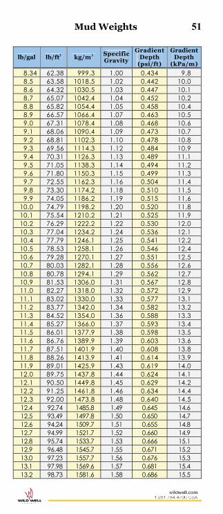
Mud Weights 51
lb/gal lb/ft3 kg/m3 Specific Gravity
Gradient Depth
(psi/ft)
Gradient Depth
(kPa/m)
8.34 62.38 999.3 1.00 0.434 9.8 8.5 63.58 1018.5 1.02 0.442 10.0 8.6 64.32 1030.5 1.03 0.447 10.1 8.7 65.07 1042.4 1.04 0.452 10.2 8.8 65.82 1054.4 1.05 0.458 10.4 8.9 66.57 1066.4 1.07 0.463 10.5 9.0 67.31 1078.4 1.08 0.468 10.6 9.1 68.06 1090.4 1.09 0.473 10.7 9.2 68.81 1102.3 1.10 0.478 10.8 9.3 69.56 1114.3 1.12 0.484 10.9 9.4 70.31 1126.3 1.13 0.489 11.1 9.5 71.05 1138.3 1.14 0.494 11.2 9.6 71.80 1150.3 1.15 0.499 11.3 9.7 72.55 1162.3 1.16 0.504 11.4 9.8 73.30 1174.2 1.18 0.510 11.5 9.9 74.05 1186.2 1.19 0.515 11.6
10.0 74.79 1198.2 1.20 0.520 11.8 10.1 75.54 1210.2 1.21 0.525 11.9 10.2 76.29 1222.2 1.22 0.530 12.0 10.3 77.04 1234.2 1.24 0.536 12.1 10.4 77.79 1246.1 1.25 0.541 12.2 10.5 78.53 1258.1 1.26 0.546 12.4 10.6 79.28 1270.1 1.27 0.551 12.5 10.7 80.03 1282.1 1.28 0.556 12.6 10.8 80.78 1294.1 1.29 0.562 12.7 10.9 81.53 1306.0 1.31 0.567 12.8 11.0 82.27 1318.0 1.32 0.572 12.9 11.1 83.02 1330.0 1.33 0.577 13.1 11.2 83.77 1342.0 1.34 0.582 13.2 11.3 84.52 1354.0 1.36 0.588 13.3 11.4 85.27 1366.0 1.37 0.593 13.4 11.5 86.01 1377.9 1.38 0.598 13.5 11.6 86.76 1389.9 1.39 0.603 13.6 11.7 87.51 1401.9 1.40 0.608 13.8 11.8 88.26 1413.9 1.41 0.614 13.9 11.9 89.01 1425.9 1.43 0.619 14.0 12.0 89.75 1437.8 1.44 0.624 14.1 12.1 90.50 1449.8 1.45 0.629 14.2 12.2 91.25 1461.8 1.46 0.634 14.4 12.3 92.00 1473.8 1.48 0.640 14.5 12.4 92.74 1485.8 1.49 0.645 14.6 12.5 93.49 1497.8 1.50 0.650 14.7 12.6 94.24 1509.7 1.51 0.655 14.8 12.7 94.99 1521.7 1.52 0.660 14.9 12.8 95.74 1533.7 1.53 0.666 15.1 12.9 96.48 1545.7 1.55 0.671 15.2 13.0 97.23 1557.7 1.56 0.676 15.3 13.1 97.98 1569.6 1.57 0.681 15.4 13.2 98.73 1581.6 1.58 0.686 15.5

52 Mud Weights
lb/gal lb/ft3 kg/m3 Specific Gravity
Gradient Depth
(psi/ft)
Gradient Depth
(kPa/m)
13.3 99.48 1593.6 1.60 0.692 15.6 13.4 100.22 1605.6 1.61 0.697 15.8 13.5 100.97 1617.6 1.62 0.702 15.9 13.6 101.72 1629.6 1.63 0.707 16.0 13.7 102.47 1641.5 1.64 0.712 16.1 13.8 103.22 1653.5 1.65 0.718 16.2 13.9 103.96 1665.5 1.67 0.723 16.4 14.0 104.71 1677.5 1.68 0.728 16.5 14.1 105.46 1689.5 1.69 0.733 16.6 14.2 106.21 1701.5 1.70 0.738 16.7 14.3 106.96 1713.4 1.72 0.744 16.8 14.4 107.70 1725.4 1.73 0.749 16.9 14.5 108.45 1737.4 1.74 0.754 17.1 14.6 109.20 1749.4 1.75 0.759 17.2 14.7 109.95 1761.4 1.76 0.764 17.3 14.8 110.70 1773.3 1.78 0.770 17.4 14.9 111.44 1785.3 1.79 0.775 17.5 15.0 112.19 1797.3 1.80 0.780 17.6 15.1 112.94 1809.3 1.81 0.785 17.8 15.2 113.69 1821.3 1.82 0.790 17.9 15.3 114.44 1833.3 1.84 0.796 18.0 15.4 115.18 1845.2 1.85 0.801 18.1 15.5 115.93 1857.2 1.86 0.806 18.2 15.6 116.68 1869.2 1.87 0.811 18.3 15.7 117.43 1881.2 1.88 0.816 18.5 15.8 118.18 1893.2 1.90 0.822 18.6 15.9 118.92 1905.1 1.91 0.827 18.7 16.0 119.67 1917.1 1.92 0.832 18.8 16.1 120.42 1929.1 1.93 0.837 18.9 16.2 121.17 1941.1 1.94 0.842 19.1 16.3 121.91 1953.1 1.96 0.846 19.2 16.4 122.66 1965.1 1.97 0.853 19.3 16.5 123.41 1977.0 1.98 0.858 19.4 16.6 124.16 1989.0 2.00 0.863 19.5 16.7 124.91 2001.0 2.01 0.868 19.6 16.8 125.65 2013.0 2.02 0.874 19.8 16.9 126.40 2025.0 2.03 0.879 19.9 17.0 127.15 2036.9 2.04 0.884 20.0 17.1 127.90 2048.9 2.05 0.889 20.1 17.2 128.65 2060.9 2.06 0.894 20.2 17.3 129.39 2072.9 2.08 0.900 20.3 17.4 130.14 2084.9 2.09 0.905 20.5 17.5 130.89 2096.9 2.10 0.910 20.6 17.6 131.64 2108.8 2.11 0.915 20.7 17.7 132.39 2120.8 2.12 0.920 20.8 17.8 133.13 2132.8 2.14 0.926 20.9 17.9 133.88 2144.8 2.15 0.931 21.1 18.0 134.63 2156.8 2.16 0.936 21.2 18.1 135.38 2168.8 2.17 0.941 21.3

Mud Weights 53
lb/gal lb/ft3 kg/m3 Specific Gravity
Gradient Depth
(psi/ft)
Gradient Depth
(kPa/m)
18.2 136.13 2180.7 2.18 0.946 21.4 18.3 136.87 2192.7 2.20 0.952 21.5 18.4 137.62 2204.7 2.21 0.957 21.6 18.5 138.37 2216.7 2.22 0.962 21.8 18.6 139.12 2228.7 2.23 0.967 21.9 18.7 139.87 2240.6 2.24 0.972 22.0 18.8 140.61 2252.6 2.26 0.978 22.1 18.9 141.36 2264.6 2.27 0.983 22.2 19.0 142.11 2276.6 2.28 0.988 22.3 19.1 142.86 2288.6 2.29 0.993 22.5 19.2 143.61 2300.6 2.30 0.998 22.6 19.3 144.35 2312.5 2.32 1.004 22.7 19.4 145.10 2324.5 2.33 1.009 22.8 19.5 145.85 2336.5 2.34 1.014 22.9 19.6 146.60 2348.5 2.35 1.019 23.1 19.7 147.34 2360.5 2.36 1.024 23.2 19.8 148.09 2372.4 2.38 1.030 23.3 19.9 148.84 2384.4 2.39 1.035 23.4 20.0 149.59 2396.4 2.40 1.040 23.5
Specifications for BOP Flanges, Ring Gaskets, and Flange Bolts & Nuts
NOTE: Acceptable flange ring gasket material for sweet oil applications is low-carbon steel and for sour oil or gas is type 316 stainless or type 304 stainless steel. ASTM A-193 Grade B/M with a maximum Rockwell Hardness of 22 may be acceptable but should be derated as per Table 1.4B of API Spec 6A. Specifications as per API Spec 6A "Wellhead Equipment".
Stack Rating Approved Flanges
Approved Ring Gaskets
Bolt Spec.
Nut Spec.
2000 psi and
3000 psi
API type 6B with type R flat
Bottom Groove API Type RX
ASTM Grade
B-7
ASTM Grade
2-H
5000 psi
API Type 6B with Type R Flat Bottom groove
or API Type 6BX with Type BX Groove
API Type RX or
API Type BX with Type
6BX Flange
ASTM Grade
B-7
ASTM Grade
2-H
10,000 psi
API Type 6BX with Type BX Groove API Type BX
ASTM Grade
B-7
ASTM Grade
2-H
Bolt Size (In.)
Torque (Ft-Lb)
¾ - 10 UNC 200 ⅞ - 9 UNC 325 1 - 8 UNC 475 1 ⅛ - 8 UN 600 1 ½ - 8 UN 1400 1 ⅝ - 8 UN 1700 1 ¾ - 8 UN 2040 1 ⅞ - 8 UN 3220

54 Gate Valve Data
SSiizzee,, WWoorrkkiinngg PPrreessssuurree aanndd NNuummbbeerr ooff TTuurrnnss ttoo OOppeerraattee
Cameron W-K-M
Cameron valves have a round handwheel with the name “Cameron” embossed on it. Operate Cameron Valves full open or full close, then back off ¼ turn.
W-K-M valves have a unique wedge shaped handwheel. Operate W-K-M valves full open or full close, then jam tight.
3,000/5,000 psi WP 3,000/5,000 psi WP Model Inches Turns Model Inches Turns
F, FC & FL
2 1/16 12 1/2
M
2 1/16 13 2 9/16 15 1/4 2 9/16 16 3 1/8 18 1/4 3 1/8 20 4 1/16 23 1/2 4 1/16 25
10,000 psi WP 10,000 - 15,000 psi WP
FC, FL & FLS
1 13/16 12 1/2
M-1 & M-2
1 13/16 14 2 1/16 12 1/2 2 1/16 12 2 9/16 15 1/4 2 9/16 15 3 1/16 18 1/4 3 1/16 17 1/2 4 1/16 23 1/2 4 1/16 23
15,000 – 20,000 psi WP 20,000 psi WP
FLS
1 13/16 12 1/2
M-3
1 13/16 15 2 1/16 12 1/2 2 1/16 16 1/2 2 9/16 15 3/4 2 9/16 19 1/2 3 1/16 22 7/8 3 1/16 23 4 1/16 29 1/2 4 1/16 29
15,000 – 20,000 psi WP
F, FC & FL
1 13/16 12 1/2
2 1/16 12 1/2 2 9/16 15 3/4 3 1/16 15 1/4 4 1/16 29 1/2
10,000 psi WP
J & JS
1 13/16 12
2 1/16 12 2 9/16 17 1/4 3 1/16 21 1/2 4 1/16 23
15,000 psi WP
J & JS
1 13/16 15 3/4
2 1/16 15 3/4 2 9/16 19 1/2 3 1/16 135 Torque
Multiplier 20,000 psi WP
J & JS
1 13/16 15 3/4
2 1/16 15 3/4 2 9/16 117 Torque
Multiplier 3 1/16 135 Torque
Multiplier

Gate Valve Data 55
SSiizzee,, WWoorrkkiinngg PPrreessssuurree aanndd NNuummbbeerr ooff TTuurrnnss ttoo OOppeerraattee
Ingram Cactus McEvoy
Ingram Cactus valves have a round handwheel with three spokes and the name “Ingram Cactus” embossed on it. Operate Ingram Cactus valves Model 205 and 215 full open or full close, then jam tight. Operate Model 405 and 315 full open or full close, then back off ¼ turn.
McEvoy valves have a round handwheel with the name “McEvoy” embossed on it. Operate McEvoy valves full open or full close, then back off ¼ turn.
2,000/5,000 psi WP 2,000/3,000/5,000 psi WP Model Inches Turns Model Inches Turns
205
2 1/16 13
C
2 1/16 13 2 9/16 16 2 9/16 16 3 1/8 20 3 1/8 18 4 1/16 25 4 1/16 17
2,000/5,000 psi WP 10,000 psi WP
405
2 1/16 16
E
1 13/16 11 2 9/16 19 2 1/16 13 3 1/8 23 2 9/16 10 1/2 4 1/16 24 1/2 3 1/16 12 1/2
4 1/16 17 10,000 – 15,000 psi WP 15,000 psi WP
215
1 13/16 14
E
1 13/16 11 2 1/16 12 2 1/16 9 2 9/16 15 2 9/16 10 1/2 3 1/16 17 1/2 3 1/16 26 4 1/16 23 4 1/16 ---
10,000 – 15,000 psi WP 10,000 psi WP
315
1 13/16 16
E-2
1 13/16 11 2 1/16 18 2 1/16 9 2 9/16 17 2 9/16 10 1/2 3 1/16 24 3 1/16 12 3/4 4 1/16 21 4 1/16 17 1/8
15,000 psi WP
E-2
1 13/16 7 3/4 2 1/16 9 2 9/16 10 1/2 3 1/16 12 3/4 4 1/16 17 1/8

56
No
min
al
F
lan
ge
Siz
e
(In
.)
Se
rvic
e
Ra
tin
g (
psi
)
Sta
nd
ard
R
ing
Ga
ske
t N
um
be
r
En
erg
ize
d R
ing
N
um
be
r O
ld A
PI
Se
rie
s D
esi
gn
ati
on
T
hro
ug
h
Bo
re I
D (
In.)
N
um
be
r
of
Bo
lts
Bo
lt S
ize
(I
n.)
B
olt
Cir
cle
(I
n.)
F
lan
ge
D
iam
ete
r (I
n.)
F
lan
ge
T
hic
kn
ess
(In
.)
1 13
/ 16
10M
BX15
1
1 13
/ 16
8 ¾
5
¾
7 ⅜
1
21/ 3
2 15
M
BX
151
1
13/ 1
6 8
⅞
6 5 /
16
8 3 /
16
1 25
/ 32
20M
BX15
1
1 13
/ 16
8 1
8 10
⅛
2 ½
2 1 /
16
2M
R23
RX23
2"
600
2
1 /16
8
⅝
5 6
½
1 5 /
16
5M
R24
RX24
2"
1,5
00
2 1 /
16
8 ⅞
6
½
8 ½
1
13/ 1
6 10
M
BX
152
2
1 /16
8
¾
6 ¼
7 ⅞
1
47/ 6
4 15
M
BX
152
2
1 /16
8
⅞
6 ⅞
8
¾
2 20
M
B
X152
2 1 /
16
8 1 ⅛
9
1 /16
11
5 /16
2
13/ 1
6
2 9 /
16
2M
R26
RX26
2
½" 6
00
2 9 /
16
8 ¾
5 ⅞
7
½
1 7 /
16
5M
R27
RX27
2
½" 1
,500
2
9 /16
8
1
7 ½
9 ⅝
1
15/ 1
6 10
M
BX
153
2
9 /16
8
7 /8
7 ¼
9 ⅛
2
1 /64
15
M
BX
153
2
9 /16
8
1
7 ⅞
10
2
¼
20M
BX15
3
2 9 /
16
8 1
¼
10 5 /
16
12 13
/ 16
3 ⅛
3 1 /
16
10M
BX15
4
3 1 /
16
8 1
8
½
10 ⅝
2
19/ 6
4 15
M
BX
154
3
1 /16
8
1 ⅛
9
1 /16
11
5 /16
2
17/ 3
2 20
M
BX
154
3
1 /16
8
1 ⅜
11
5 /16
14
1 /16
3 ⅜
3 ⅛
2M
R3
1 RX
31
3" 6
00
3 ⅛
8
¾
6 ⅝
8
¼
1 9 /
16
3M
R31
RX31
3"
900
3 ⅛
8
⅞
7 ½
9
½
1 13
/ 16
5M
R35
RX35
3"
1,5
00
3 ⅛
8
1 ⅛
8
10 ½
2
3 /16
API Ring Joint Flanges

57 N
om
ina
l
Fla
ng
e S
ize
(I
n.)
Se
rvic
e
Ra
tin
g (
psi
)
Sta
nd
ard
R
ing
Ga
ske
t N
um
be
r
En
erg
ize
d R
ing
N
um
be
r O
ld A
PI
Se
rie
s D
esi
gn
ati
on
T
hro
ug
h
Bo
re I
D (
In.)
N
um
be
r
of
Bo
lts
Bo
lt S
ize
(I
n.)
B
olt
Cir
cle
(I
n.)
F
lan
ge
D
iam
ete
r (I
n.)
F
lan
ge
T
hic
kn
ess
(In
.)
4 1 /
16
2M
R37
RX37
4"
600
4
1 /16
8
⅞
8 ½
10
¾
1 13
/ 16
3M
R37
RX37
4"
900
4
1 /16
8
1 ⅛
9
¼
11 ½
2
1 /16
5M
R3
9 RX
39
4" 1
,500
4
1 /16
8
1 ¼
9
½
12 ¼
2
7 /16
10
M
BX
155
4
1 /16
8
1 ⅛
10
3 /16
12
7 /16
2
49/ 6
4 15
M
BX
155
4
1 /16
8
1 ⅜
11
7 /16
14
3 /16
3
3 /32
20
M
BX
155
4
1 /16
8
1 ¾
14
1 /16
17
9 /16
4
3 /16
5 ⅛
2M
R41
RX41
5 ⅛
8
1
10 ½
13
2
1 /16
3M
R4
1 RX
41
5 ⅛
8
1 ¼
11
13
¾
2 5 /
16
5M
R44
RX44
5 ⅛
8
1 ½
11
½
14 ¾
3
3 /16
10
M
BX
169
5 ⅛
12
1 ⅛
11
13/ 1
6 14
1 /16
3 ⅛
7 1 /
16
2M
R45
RX45
6"
600
7
1 /16
12
1
11
½
14
2 3 /
16
3M
R45
RX45
6"
900
7
1 /16
12
1 ⅛
12
½
15
2 ½
5M
R4
6 RX
46
6" 1
,500
7
1 /16
12
1 ⅜
12
½
15 ½
3 ⅝
10
M
BX
156
7
1 /16
12
1
½
15 ⅞
18
⅞
4 1 /
16
15M
BX15
6
7 1 /
16
16
1 ½
16
⅞
19 ⅞
4
11/ 1
6 20
M
BX
156
7
1 /16
16
2
21 13
/ 16
25 13
/ 16
6 ½
9
2M
R49
RX49
8"
600
9
12
1 ⅛
13
¾
16 ½
2
½
3M
R49
RX49
8"
900
9
12
1 ⅜
15
½
18 ½
2
13/ 1
6 5M
R5
0 RX
50
8" 1
,500
9
12
1 ⅝
15
½
19
4 1 /
16
10M
BX15
7
9 16
1
½
18 ¾
21
¾
4 ⅞
15
M
BX
157
9
16
1 ⅞
21
¾
25 ½
5
¾
API Ring Joint Flanges

58 N
om
ina
l
Fla
ng
e S
ize
(I
n.)
Se
rvic
e
Ra
tin
g (
psi
)
Sta
nd
ard
R
ing
Ga
ske
t N
um
be
r
En
erg
ize
d R
ing
N
um
be
r O
ld A
PI
Se
rie
s D
esi
gn
ati
on
T
hro
ug
h
Bo
re I
D (
In.)
N
um
be
r
of
Bo
lts
Bo
lt S
ize
(I
n.)
B
olt
Cir
cle
(I
n.)
F
lan
ge
D
iam
ete
r (I
n.)
F
lan
ge
T
hic
kn
ess
(In
.)
11
2M
R53
RX53
10
" 600
11
16
1
¼
17
20
2 13
/ 16
3M
R53
RX53
10
" 900
11
16
1 ⅜
18
½
21 ½
3
1 /16
5M
R5
4 RX
54
10" 1
,500
11
12
1 ⅞
19
23
4
11/ 1
6 10
M
BX
158
11
16
1
¾
22 ¼
25
¾
5 9 /
16
15M
BX15
8
11
20
2
28
32
7 ⅜
13 ⅝
2M
R57
RX57
12
" 600
13
⅝
20
1 ¼
19
¼
22
2 15
/ 16
3M
R57
RX57
12
" 900
13
⅝
20
1 ⅜
21
24
3
7 /16
5M
BX16
0
13 ⅝
16
1 ⅝
23
¼
26 ½
4
7 /16
10
M
BX
159
13
⅝
20
1 ⅞
26
½
30 ¼
6 ⅝
15
M
BX
159
13
⅝
20
2 ¼
30
⅜
34 ⅞
7 ⅞
16 ¾
2M
R6
5 RX
65
16" 6
00
16 ¾
20
1
½
23 ¾
27
3
5 /16
3M
R6
6 RX
66
16" 9
00
16 ¾
20
1 ⅝
24
¼
27 ¾
3
15/ 1
6 5M
BX16
2
16 ¾
16
1 ⅞
26
⅝
30 ⅜
5 ⅛
10
M
BX
162
16
¾
24
1 ⅞
30
9 /16
34
5 /16
6 ⅝
18 ¾
5M
BX16
3
18 ¾
20
2
31
⅝
35 ⅝
6
17/ 3
2 10
M
BX
164
18
¾
24
2 ¼
36
7 /16
40
15/ 1
6 8
25/ 3
2 20
¾
3M
R74
RX74
20
" 900
20
¾
20
2
29 ½
33
¾
4 ¾
21
¼
2M
R73
RX73
20
" 600
21
¼
24
1 ⅝
28
½
32
3 ⅞
21
¼
5M
BX
165
21
¼
24
2 34
⅞
39
7 ⅛
21
¼
10M
BX16
6
21 ¼
24
2
½
40 ¼
45
9
½
26 ¾
2M
BX16
7
26 ¾
20
1
¾
37 ½
41
4
31/ 3
2 3M
BX16
8
26 ¾
24
2
39 ⅜
43
⅜
6 11
/ 32
API Ring Joint Flanges

BOP Fluid Operating Volumes 59
CCaammeerroonn BBOOPPss Cameron Type 'D' Annular Preventer
BOP Nom. Size (In.)
Working Pressure (psi)
Fluid to Close (gal)
Fluid to Open (gal)
7 1/16 5,000 1.69 1.39
10,000 2.94 2.55
11 5,000 5.65 4.69 10,000 10.15 9.06
13 5/8 5,000 12.12 10.34
10,000 18.10 16.15
Cameron Type 'UM' Ram Preventer BOP Nom. Size
(In.) Working
Pressure (psi) Fluid to Close
(gal) Fluid to Open
(gal)
7 1/16
3,000 2.3 2.2 5,000 2.3 2.2
10,000 2.3 2.2 15,000 2.3 2.2
11 10,000 6.2 6.2 15,000 7.3 7.3
13 5/8 5,000 7.5 7.5
10,000 7.5 7.5
Cameron Type 'U' Ram Preventer
BOP Nom. Size (Old API Series
Designation) In.
Working Pressure (psi)
Fluid to Close (gal)
Fluid to Open (gal)
7 1/16 (6) 3,000 1.3 1.3 5,000 1.3 1.3
7 1/16 10,000 1.3 1.3 15,000 1.3 1.3
11 (10) 3,000 3.5 3.4 5,000 3.5 3.4
11 10,000 3.5 3.4 15,000 5.8 5.7
13 5/8 (12) 3,000 5.8 5.5
13 5/8 5,000 5.8 5.5
10,000 5.8 5.5 15,000 10.6 10.4
16 3/4 3,000 10.6 9.8 5,000 10.6 9.8
10,000 12.5 11.6 18 3/4 10,000 23.1 21.3
20 3/4 (20) 3,000 8.7 8.1
21 1/4 2,000 8.7 9.0 5,000 30.0 27.3
10,000 26.9 24.5 26 3/4 3,000 10.8 10.1

60 BOP Fluid Operating Volumes
Cameron Type 'QRC' Ram Preventer
BOP Nom. Size (Old API Series
Designation) In.
Working Pressure (psi)
Fluid to Close (gal)
Fluid to Open (gal)
7 1/16 (6) 3,000 0.81 0.95 5,000 0.81 0.95
9 (8) 3,000 2.36 2.70 5,000 2.36 2.70
11 (10) 3,000 2.77 3.18 5,000 2.77 3.18
13 5/8 (12) 3,000 4.42 5.10 16 3/4 (16) 2,000 6.00 7.05 17 3/4 (18) 2,000 6.00 7.05
Cameron Hydraulic Gate Valves
Type Valve Size
(In.)
Working Pressure
(psi)
Fluid to Close (gal)
Fluid to Open (gal)
HCR 4 3,000 0.52 0.61 HCR 4 5,000 0.52 0.61 HCR 6 3,000 1.95 2.25 HCR 6 5,000 1.95 2.25
F 4 3,000 0.30 0.30 F 4 5,000 0.30 0.30 F 4 10,000 0.59 0.59 F 6 3,000 0.84 0.84 F 6 5,000 0.84 0.84
SShhaaffffeerr BBOOPPss Shaffer Spherical Annular Preventer
BOP Nom. Size (In.)
Working Pressure (psi)
Cover Type
Fluid to Close (gal)
Fluid to Open (gal)
7 1/16 3,000 Bolted 4.57 3.21 5,000 Bolted 4.57 3.21
10,000 Bolted 17.11 13.95
9 3,000 Bolted 7.23 5.03 5,000 Bolted 11.05 8.72
11 3,000 Bolted 11.00 6.78 5,000 Bolted 18.67 14.59
10,000 Wedge 30.58 24.67
13 5/8 3,000 Bolted 23.50 14.67 5,000 Bolt/Wedge 23.58 17.41
10,000 Wedge 40.16 32.64 16 3/4 5,000 Wedge 33.26 25.61 18 3/4 5,000 Wedge 48.16 37.61 21 1/4 2,000 Bolted 32.59 16.92
5,000 Wedged 61.37 47.76

BOP Fluid Operating Volumes 61
Shaffer Type 'LXT' Ram Preventer BOP Nom. Size (In.)
Working Pressure (psi)
Fluid to Close (gal)
Fluid to Open (gal)
7 3,000 0.32 0.33 5,000 0.32 0.33
11 3,000 2.80 2.46 5,000 2.80 2.46
Shaffer Type 'NXT' Ram Preventer
BOP Nom. Size (In.)
Working Pressure (psi)
Type Fluid to Close (gal)
Fluid to Open (gal)
18 3/4
5,000 Poslock 14.04 12.74
5,000 Booster (Poslock) 31.22 29.92
5,000 Manual-Lock 13.14 12.84 5,000 Ultralock IIB 16.74 15.44
10,000 Poslock 14.04 13.02
10,000 Booster (Poslock) 31.22 29.92
10,000 Manual-Lock 13.14 13.14 10,000 Ultralock IIB 16.74 15.72 15,000 Poslock 14.04 13.02
15,000 Booster (Poslock) 31.22 29.92
15,000 Manual-Lock 13.14 13.14 15,000 Ultralock IIB 16.74 15.72
Shaffer Type 'LWS' Ram Preventer
BOP Nom. Size (In.)
Working Pressure (psi)
Piston Size (In.)
Fluid to Close (gal)
Fluid to Open (gal)
4 1/16 5,000 6 0.59 0.52
10,000 6 0.59 0.52
7 1/16 5,000 6 ½ 1.45 1.18
10,000 14 5.18 5.25 9 5,000 8 ½ 2.58 2.27
11 3,000 6 ½ 1.74 1.45 5,000 8 ½ 2.98 2.62 5,000 14 9.50 8.90
20 3/4 3,000 8 ½ 5.07 4.46 3,000 10 7.80 6.86 3,000 14 14.50 13.59
21 1/4 2,000 8 ½ 5.07 4.46 2,000 10 7.80 6.86 2,000 14 14.50 13.59

62 BOP Fluid Operating Volumes
Shaffer Type 'SL/SLX' Ram Preventer BOP Nom. Size (In.)
Working Pressure (psi)
Piston Size (In.)
Fluid to Close (gal)
Fluid to Open (gal)
7 1/16
10,000 10 2.72 2.34 10,000 14 6.00 5.57 15,000 10 2.72 2.34 15,000 14 6.00 5.57
11 10,000 14 9.45 7.00 15,000 14 9.40 8.10
13 5/8
3,000 10 5.44 4.46 5,000 10 5.44 4.46 5,000 14 11.00 10.52
10,000 14 10.58 10.52 15,000 14 11.56 10.52
16 3/4 5,000 10 6.07 4.97 5,000 14 11.76 10.67
10,000 14 14.47 12.50
18 3/4 10,000 14 14.55 13.21 15,000 14 14.62 13.33
21 1/4 10,000 14 16.05 13.86
Shaffer Type 'DB' Hydraulic Gate Valves Valve Size
(In.) Working Pressure
(psi) Fluid to Close
(gal) Fluid to Open
(gal)
2 1/16 5,000 0.15 0.20
10,000 0.15 0.20 15,000 0.26 0.29
3 1/8 5,000 0.20 0.25
3 1/16 10,000 0.35 0.40 15,000 0.35 0.40
4 1/16 5,000 0.35 0.40 10000 0.45 0.50 15000 0.45 0.50

BOP Fluid Operating Volumes 63
HHyyddrriill BBOOPPss Hydril Type 'GK' Annular Preventer
BOP Nom. Size (In.)
Working Pressure (psi)
Fluid to Close (gal)
Fluid to Open (gal)
7 1/16
3,000 2.85 2.24 5,000 3.86 3.30
10,000 9.42 7.08 15,000 11.20 7.50 20,000 10.90 7.20
9 3,000 4.33 3.41 5,000 6.84 5.80
10,000 15.90 11.95
11
3,000 7.43 5.54 5,000 9.81 7.98
10,000 25.10 18.97 15,000 26.67 20.45
13 5/8 3,000 11.36 8.94 5,000 17.98 14.16
10,000 37.18 12.59
16 3/4 2,000 17.46 15.80 3,000 28.70 19.93 5,000 28.70 19.93
Hydril Type 'MSP' Annular Preventer
BOP Nom. Size (In.)
Working Pressure (psi)
Fluid to Close (gal)
Fluid to Open (gal)
7 1/16 2,000 2.85 1.98 9 2,000 4.57 2.95 11 2,000 7.43 5.23
20 3/4 2,000 31.05 18.93 21 1/4 2,000 31.05 18.93 29 1/2 500 60.00 n/a
30 1,000 87.60 27.80
Hydril Type 'GX' Annular Preventer BOP Nom. Size (In.)
Working Pressure (psi)
Fluid to Close (gal)
Fluid to Open (gal)
11 10,000 17.90 17.90 15,000 24.10 24.10
13 5/8 5,000 15.50 15.50
10,000 24.10 24.10 18 3/4 10,000 58.00 58.00

64 BOP Fluid Operating Volumes
Hydril Type 'GL' Annular Preventer BOP Nom. Size (In.)
Working Pressure (psi)
Fluid to Close (gal)
Fluid to Open (gal)
Secondary Fluid (gal)
13 5/8 5,000 19.76 19.76 8.24 16 3/4 5,000 33.80 33.80 17.30 18 3/4 5,000 44.00 44.00 20.00 21 1/4 5,000 58.00 58.00 29.50
Hydril Manual Lock Ram Preventer
BOP Nom. Size (In.)
Working Pressure (psi)
Fluid to Close (gal)
Fluid to Open (gal)
7 1/16
3,000 1.00 0.93 5,000 1.00 0.93
10,000 1.90 1.80 15,000 3.70 3.40
9 3,000 1.90 1.90 5,000 1.90 1.90
11 3,000 3.30 3.20 5,000 3.30 3.20
10,000 5.20 5.00
13 5/8 3,000 5.40 4.90 5,000 5.40 4.80
10,000 12.20 11.60 18 3/4 5,000 17.10 16.10 20 3/4 3,000 8.10 7.20
21 1/4 2,000 8.10 7.20 5,000 17.50 16.60
Hydril MPL Ram Preventer BOP Nom. Size (In.)
Working Pressure (psi)
Fluid to Close (gal)
Fluid to Open (gal)
7 1/16
3,000 1.20 0.93 5,000 1.20 0.93
10,000 2.00 1.80 15,000 3.90 3.40
11 10,000 5.70 5.00 20,000 12.50 11.50
13 5/8
3,000 5.90 4.90 5,000 5.90 5.20
10,000 12.80 11.60 15,000 12.60 11.00
18 3/4 5,000 17.90 16.10
10,000 17.10 15.60 15,000 19.40 16.70
20 3/4 3,000 18.00 16.30
21 1/4 2,000 18.00 16.30 5,000 19.30 16.60
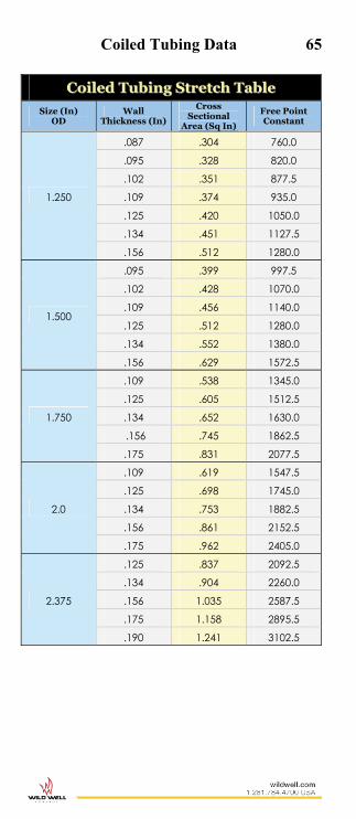
Coiled Tubing Data 65
CCooiilleedd TTuubbiinngg SSttrreettcchh TTaabbllee
Size (In) OD
Wall Thickness (In)
Cross Sectional
Area (Sq In)
Free Point Constant
1.250
.087 .304 760.0
.095 .328 820.0
.102 .351 877.5
.109 .374 935.0
.125 .420 1050.0
.134 .451 1127.5
.156 .512 1280.0
1.500
.095 .399 997.5
.102 .428 1070.0
.109 .456 1140.0
.125 .512 1280.0
.134 .552 1380.0
.156 .629 1572.5
1.750
.109 .538 1345.0
.125 .605 1512.5
.134 .652 1630.0
.156 .745 1862.5
.175 .831 2077.5
2.0
.109 .619 1547.5
.125 .698 1745.0
.134 .753 1882.5
.156 .861 2152.5
.175 .962 2405.0
2.375
.125 .837 2092.5
.134 .904 2260.0
.156 1.035 2587.5
.175 1.158 2895.5
.190 1.241 3102.5

66 O
D
Sp
eci
fie
d
Wa
ll
Sp
eci
fie
d
ID
Ca
lcu
late
d
No
m.
Wt
lbs/
ft
Inte
rna
l C
ap
aci
ty/f
t D
isp
lace
men
t o
f S
tee
l/ft
E
xte
rna
l D
isp
lace
men
t/ft
O
D
Sp
eci
fie
d
Wa
ll
Sp
eci
fie
d
ID
Ca
lcu
late
d N
om
Wt
lbs/
ft
Inte
rna
l C
ap
aci
ty
Dis
pla
cem
ent
Of
Ste
el
Ex
tern
al
Dis
pla
cem
ent
Ga
llo
ns
bb
ls
Ga
llo
ns
bb
ls
Ga
llo
ns
bb
ls
Ga
llo
ns
bb
ls
Ga
llo
ns
bb
ls
Ga
llo
ns
bb
ls
1.00
.0
80
.840
.7
88
.028
79
.000
685
.012
01
.000
29
.040
80
.000
97
1.50
.1
16
1.26
8 1.
719
.065
60
.001
562
.026
20
.000
62
.091
80
.002
19
1.00
.0
87
.826
.8
50
.027
84
.000
663
.012
96
.000
31
.040
80
.000
97
1.50
.1
25
1.25
0 1.
840
.063
75
.001
518
.028
05
.000
67
.091
80
.002
19
1.00
.0
95
.810
.9
20
.026
77
.000
637
.014
03
.000
33
.040
80
.000
97
1.50
.1
34
1.23
2 1.
960
.061
93
.001
474
.029
87
.000
71
.091
80
.002
19
1.00
.1
02
.796
.9
81
.025
85
.000
616
.014
95
.000
36
.040
80
.000
97
1.50
.1
45
1.21
0 2.
104
.059
74
.001
422
.032
06
.000
76
.091
80
.002
19
1.00
.1
09
.782
1.
040
.024
95
.000
594
.015
85
.000
38
.040
80
.000
97
1.50
.1
56
1.18
8 2.
245
.057
58
.001
371
.034
22
.000
81
.091
80
.002
19
1.25
.0
80
1.09
0 1.
002
.048
47
.001
154
.015
28
.000
36
.063
75
.001
52
1.50
.1
75
1.15
0 2.
483
.053
96
.001
285
.037
84
.000
90
.091
80
.002
19
1.25
.0
87
1.07
6 1.
083
.047
24
.001
125
.016
51
.000
39
.063
75
.001
52
1.50
.1
90
1.12
0 2.
665
.051
18
.001
219
.040
62
.000
97
.091
80
.002
19
1.25
.0
95
1.06
0 1.
175
.045
84
.001
091
.017
91
.000
43
.063
75
.001
52
1.75
.1
09
1.53
2 1.
915
.095
76
.002
280
.029
19
.000
70
.124
95
.002
98
1.25
.1
02
1.04
6 1.
254
.044
64
.001
063
.019
11
.000
46
.063
75
.001
52
1.75
.1
16
1.51
8 2.
029
.094
02
.002
238
.030
93
.000
74
.124
95
.002
98
1.25
.1
09
1.03
2 1.
332
.043
45
.001
035
.020
30
.000
48
.063
75
.001
52
1.75
.1
25
1.50
0 2.
175
.091
80
.002
186
.033
15
.000
79
.124
95
.002
98
1.25
.1
16
1.01
8 1.
408
.042
28
.001
007
.021
47
.000
51
.063
75
.001
52
1.75
.1
34
1.48
2 2.
318
.089
61
.002
134
.035
34
.000
84
.124
95
.002
98
1.25
.1
25
1.00
0 1.
506
.040
80
.000
971
.022
95
.000
55
.063
75
.001
52
1.75
.1
45
1.46
0 2.
492
.086
97
.002
071
.037
98
.000
90
.124
95
.002
98
1.25
.1
34
.982
1.
601
.039
34
.000
937
.024
41
.000
58
.063
75
.001
52
1.75
.1
56
1.43
8 2.
662
.084
37
.002
009
.040
58
.000
97
.124
95
.002
98
1.25
.1
45
.960
1.
715
.037
60
.000
895
.026
15
.000
62
.063
75
.001
52
1.75
.1
75
1.40
0 2.
951
.079
97
.001
904
.044
98
.001
07
.124
95
.002
98
1.25
.1
56
.938
1.
827
.035
90
.000
855
.027
85
.000
66
.063
75
.001
52
1.75
.1
88
1.37
4 3.
140
.077
03
.001
834
.047
92
.001
14
.124
95
.002
98
1.25
.1
75
.900
2.
014
.033
05
.000
787
.030
70
.000
73
.063
75
.001
52
1.75
.1
90
1.37
0 3.
173
.076
58
.001
823
.048
37
.001
15
.124
95
.002
98
1.50
.0
95
1.31
0 1.
429
.070
02
.001
667
.021
78
.000
52
.091
80
.002
19
2.00
.1
09
1.78
2 2.
207
.129
56
.003
085
.033
64
.000
80
.163
20
.003
89
1.50
.1
02
1.29
6 1.
527
.068
53
.001
632
.023
27
.000
55
.091
80
.002
19
2.00
.1
16
1.76
8 2.
340
.127
53
.003
037
.035
67
.000
85
.163
20
.003
89
1.50
.1
09
1.28
2 1.
623
.067
06
.001
597
.024
74
.000
59
.091
80
.002
19
2.00
.1
25
1.75
0 2.
509
.124
95
.002
975
.038
25
.000
91
.163
20
.003
89
Coiled Tubing Dimensions

67 O
D
Sp
eci
fie
d
Wa
ll
Sp
eci
fie
d
ID
Ca
lcu
late
d
No
m.
Wt
lbs/
ft
Inte
rna
l C
ap
aci
ty/f
t D
isp
lace
men
t o
f S
tee
l/ft
E
xte
rna
l D
isp
lace
men
t/ft
O
D
Sp
eci
fie
d
Wa
ll
Sp
eci
fie
d
ID
Ca
lcu
late
d N
om
Wt
lbs/
ft
Inte
rna
l C
ap
aci
ty
Dis
pla
cem
ent
Of
Ste
el
Ex
tern
al
Dis
pla
cem
ent
Ga
llo
ns
bb
ls
Ga
llo
ns
bb
ls
Ga
llo
ns
bb
ls
Ga
llo
ns
bb
ls
Ga
llo
ns
bb
ls
Ga
llo
ns
bb
ls
2.00
.1
34
1.73
2 2.
677
.122
39
.002
914
.040
81
.000
97
.163
20
.003
89
2.87
5 .1
56
2.56
3 4.
541
.268
01
.006
381
.069
22
.001
65
.337
24
.008
03
2.00
.1
45
1.71
0 2.
880
.119
30
.002
841
.043
90
.001
05
.163
20
.003
89
2.87
5 .1
75
2.52
5 5.
059
.260
13
.006
193
.077
11
.001
84
.337
24
.008
03
2.00
.1
56
1.68
8 3.
080
.116
25
.002
768
.046
95
.001
12
.163
20
.003
89
2.87
5 0.
188
2.49
9 5.
400
.254
80
.006
067
.082
44
.001
96
.337
24
.008
03
2.00
.1
75
1.65
0 3.
419
.111
08
.002
645
.052
12
.001
24
.163
20
.003
89
2.87
5 0.
190
2.49
5 5.
462
.253
98
.006
047
.083
26
.001
98
.337
24
.008
03
2.00
.1
88
1.62
4 3.
640
.107
60
.002
562
.055
60
.001
32
.163
20
.003
89
2.87
5 0.
203
2.46
9 5.
790
.248
72
.005
922
.088
52
.002
11
.337
24
.008
03
2.00
.1
90
1.62
0 3.
682
.107
08
.002
549
.056
12
.001
34
.163
20
.003
89
2.87
5 0.
204
2.46
7 5.
834
.248
31
.005
912
.088
93
.002
12
.337
24
.008
03
2.00
.2
03
1.59
4 3.
900
.103
67
.002
468
.059
53
.001
42
.163
20
.003
89
3.50
0 0.
134
3.23
2 4.
820
.426
19
.010
147
.073
61
.001
75
.499
80
.011
90
2.00
.2
04
1.59
2 3.
923
.103
41
.002
462
.059
79
.001
42
.163
20
.003
89
3.50
0 0.
156
3.18
8 5.
570
.414
66
.009
873
.085
14
.002
03
.499
80
.011
90
2.37
5 .1
25
2.12
5 3.
011
.184
24
.004
387
.045
90
.001
09
.230
14
.005
48
3.50
0 0.
175
3.15
0 6.
230
.404
84
.009
639
.094
96
.002
26
.499
80
.011
90
2.37
5 .1
34
2.10
7 3.
215
.181
13
.004
313
.049
01
.001
17
.230
14
.005
48
3.50
0 0.
188
3.12
4 6.
650
.398
18
.009
481
.101
62
.002
42
.499
80
.011
90
2.37
5 .1
45
2.08
5 3.
462
.177
37
.004
223
.052
77
.001
26
.230
14
.005
48
3.50
0 0.
190
3.12
0 6.
733
.397
16
.009
456
.102
64
.002
44
.499
80
.011
90
2.37
5 .1
56
2.06
3 3.
706
.173
64
.004
134
.056
49
.001
35
.230
14
.005
48
3.50
0 0.
203
3.09
4
7.15
0 .3
9057
.0
0929
9 .1
0923
.0
0260
.4
9980
.0
1190
2.
375
.175
2.
025
4.12
2 .1
6731
.0
0398
3 .0
6283
.0
0150
.2
3014
.0
0548
3.
500
0.20
4 3.
092
7.19
9 .3
9007
.0
0928
7 .1
0973
.0
0261
.4
9980
.0
1190
2.
375
.188
1.
999
4.39
0 .1
6304
.0
0388
2 .0
6710
.0
0160
.2
3014
.0
0548
3.
500
0.22
4 3.
052
7.85
7 .3
8004
.0
0904
9 .1
1976
.0
0285
.4
9980
.0
1190
2.
375
.190
1.
995
4.44
5 .1
6239
.0
0386
6 .0
6775
.0
0161
.2
3014
.0
0548
3.
500
0.25
0 3.
000
8.69
9 .3
6720
.0
0874
3 .1
3260
.0
0316
.4
9980
.0
1190
2.
375
.203
1.
969
4.71
0 .1
5818
.0
0376
6 .0
7196
.0
0171
.2
3014
.0
0548
4.
500
0.20
4 4.
092
9.38
3 .6
8317
.0
1626
6 .1
4303
.0
0341
.8
2620
.0
1967
2.
375
.204
1.
967
4.74
2 .1
5786
.0
0375
9 .0
7228
.0
0172
.2
3014
.0
0548
4.
500
0.22
4 4.
052
10.2
55
.669
88
.015
950
.156
32
.003
72
.826
20
.019
67
2.87
5 .1
25
2.62
5 3.
670
.281
14
.006
694
.056
10
.001
34
.337
24
.008
03
4.50
0 0.
250
4.00
0 11
.376
.6
5280
.0
1554
3 .1
7340
.0
0413
.8
2620
.0
1967
Coiled Tubing Dimensions
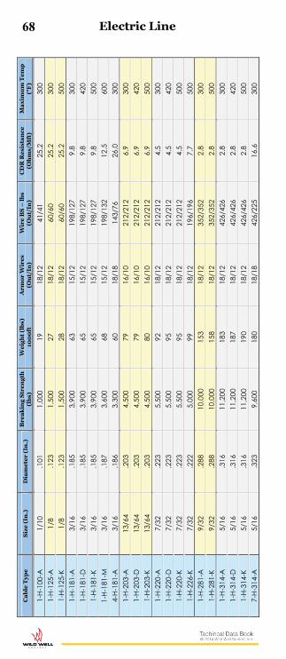
68 C
ab
le T
ype
S
ize
(In
.)
Dia
me
ter
(In
.)
Bre
ak
ing
Str
eng
th
(lb
s)
Wei
gh
t (l
bs)
10
00
ft
Arm
or
Wir
es
(Ou
t/In
) W
ire
BS
– l
bs
(Ou
t/In
) C
DR
Res
ista
nce
(O
hm
s/M
ft)
Ma
xim
um
Tem
p
(°F
)
1-H-
100-
A
1/10
.1
01
1,00
0 19
18
/12
41/4
1 25
.2
300
1-H-
125-
A
1/8
.123
1,
500
27
18/1
2 60
/60
25.2
30
0 1-
H-12
5-K
1/8
.123
1,
500
28
18/1
2 60
/60
25.2
50
0 1-
H-18
1-A
3/
16
.185
3,
900
63
15/1
2 19
8/12
7 9.
8 30
0 1-
H-18
1-D
3/
16
.185
3,
900
65
15/1
2 19
8/12
7 9.
8 42
0 1-
H-18
1-K
3/16
.1
85
3,90
0 65
15
/12
198/
127
9.8
500
1-H-
181-
M
3/16
.1
87
3,60
0 68
15
/12
198/
132
12.5
60
0 4-
H-18
1-A
3/
16
.186
3,
300
60
18/1
8 14
3/76
26
.0
300
1-H-
203-
A
13/6
4 .2
03
4,50
0 79
16
/10
212/
212
6.9
300
1-H-
203-
D
13/6
4 .2
03
4,50
0 79
16
/10
212/
212
6.9
420
1-H-
203-
K 13
/64
.203
4,
500
80
16/1
0 21
2/21
2 6.
9 50
0 1-
H-22
0-A
7/
32
.223
5,
500
92
18/1
2 21
2/21
2 4.
5 30
0 1-
H-22
0-D
7/
32
.223
5,
500
95
18/1
2 21
2/21
2 4.
5 42
0 1-
H-22
0-K
7/32
.2
23
5,50
0 95
18
/12
212/
212
4.5
500
1-H-
226-
K 7/
32
.222
5,
000
99
18/1
2 19
6/19
6 7.
7 50
0 1-
H-28
1-A
9/
32
.288
10
,000
15
3 18
/12
352/
352
2.8
300
1-H-
281-
K 9/
32
.288
10
,000
15
8 18
/12
352/
352
2.8
500
1-H-
314-
A
5/16
.3
16
11,2
00
183
18/1
2 42
6/42
6 2.
8 30
0 1-
H-31
4-D
5/
16
.316
11
,200
18
7 18
/12
426/
426
2.8
420
1-H-
314-
K 5/
16
.316
11
,200
19
0 18
/12
426/
426
2.8
500
7-H-
314-
A
5/16
.3
23
9,60
0 18
0 18
/18
426/
225
16.6
30
0
Electric Line

69 C
ab
le T
ype
S
ize
(In
.)
Dia
me
ter
(In
.)
Bre
ak
ing
Str
eng
th
(lb
s)
Wei
gh
t (l
bs)
10
00
ft
Arm
or
Wir
es
(Ou
t/In
) W
ire
BS
– l
bs
(Ou
t/In
) C
DR
Res
ista
nce
(O
hm
s/M
ft)
Ma
xim
um
Tem
p
(°F
)
1-H-
375-
A
3/8
.375
14
,600
25
3 18
/12
595/
595
2.9
300
1-H-
375-
D
3/8
.375
14
,600
26
0 18
/12
595/
595
2.9
420
1-H-
375-
K 3/
8 .3
75
14,6
00
261
18/1
2 59
5/59
5 2.
9 50
0 3-
H-37
5-A
3/
8 .3
72
13,5
00
235
20/1
6 48
6/39
7 7.
1 30
0 4-
H-37
5-A
3/
8 .3
72
13,5
00
239
20/1
6 57
2/30
1 10
.5
300
7-H-
375-
A
3/8
.372
12
,800
24
3 18
/18
572/
301
10.5
30
0 1-
H-42
2-A
7/
16
.414
17
,800
30
7 18
/12
727/
727
2.9
300
1-H-
422-
D
7/16
.4
14
17,8
00
316
18/1
2 72
7/72
7 2.
9 42
0 1-
H-42
2-K
7/16
.4
14
17,8
00
317
18/1
2 72
7/72
7 2.
9 50
0 7-
H-42
2-A
7/
16
.426
18
,300
31
4 18
/18
766/
397
10.9
30
0 7-
H-42
2-D
7/
16
.426
18
,300
32
4 18
/18
766/
397
10.0
42
0 7-
H-42
2-K
7/16
.4
26
18,3
00
326
18/1
8 76
6/39
7 10
.0
500
7-H-
464-
A
15/3
2 .4
62
18,3
00
326
24/2
4 53
9/33
5 10
.0
300
7-H-
464-
D
15/3
2 .4
62
18,3
00
333
24/2
4 53
9/33
5 10
.0
420
7-H-
464-
K 15
/32
.462
18
,300
34
7 24
/24
539/
335
10.0
50
0 7-
H-52
0-A
17
/32
.522
26
,000
46
2 20
/16
958/
778
10.5
30
0 7-
H-52
0-D
17
/32
.522
26
,000
46
7 20
/16
958/
778
10.5
42
0 7-
H-47
2-A
Sl
amm
er
.472
22
,200
37
9 18
/18
929/
486
10.0
30
0 7-
H-47
2-D
Sl
amm
er
.472
22
,200
38
6 18
/18
929/
486
10.0
42
0 7-
H-47
2-K
Slam
mer
.4
72
22,2
00
394
18/1
8 92
9/48
6 10
.0
500
Electric Line

70
Ca
rbon
Ste
el –
API
9A
Bre
akin
g St
reng
ths
Ma
teria
l (In
) .0
72
.082
.0
92
.105
.1
08
.125
Br. S
teel
API
Lev
el 3
or i
mp
rove
d p
low
(lb
s)
961
1239
15
47
1966
21
09
2794
API
Ex.
Imp
r. Pl
ow, H
i-Str,
or M
on. A
A (l
bs)
11
50
1460
18
30
2360
24
90
3300
For w
ireln
e to
fall
agai
nst w
ell
pres
sure
, fin
d d
esire
d lin
e ve
rsus
wel
l pre
ssur
e an
d
extra
pol
ate
tota
l sin
ker b
ar
wei
ght n
eed
ed.
All
“lbs
” ar
e br
eaki
ng
stre
ngth
. Th
ese
vary
with
the
man
ufac
ture
r.
Aus
teni
tic S
tain
less
Ste
el –
Bre
akin
g St
reng
ths
Ma
teria
l (In
) .0
82
.092
.1
05
.108
.1
25
316
Stai
nles
s (lb
s)
1083
13
63
1732
17
86
2270
Sup
er A
uste
nitic
Sta
inle
ss –
Bre
aki
ng S
treng
ths
Ma
teria
l (In
) .0
92
.105
.1
08
.125
Sand
vik
Sani
cro
28 (l
bs)
14
45
1885
19
95
2675
6 M
oly
Stai
nles
s Ste
el –
Bre
akin
g St
reng
ths
Ma
teria
l (In
) .0
92
.105
.1
08
.125
Ave
sta
254
SM
O (l
bs)
1462
18
18
1924
24
54
Brid
on S
upa
(lb
s)
1550
20
30
2030
25
60
25-6
MO
(lbs
) 14
75
N/A
20
50
2550
Cob
alt
Base
d A
lloy
– Br
eaki
ng S
treng
ths
Ma
teria
l (In
) .0
92
.105
.1
08
.125
MP3
5N (l
bs)
15
82
2009
20
80
2724
Bra
ided
Lin
e –
Brea
king
Stre
ngth
s
Size
(In)
3/
16”
3/16
” 7/
32”
7/32
”
Con
stru
ctio
n 1
x 16
1x
19
(Dyc
an/D
yfor
m)
1 x
16
1x 1
9 (D
ycan
/Dyf
orm
)
Ga
lv.
Ca
rbon
Ste
el
4500
61
70
6000
83
70
15-6
Mo
(Sup
a 7
5)
4320
49
60
5842
59
90
10
00
20
00
30
00
40
00
90
00
10
00
0
50
00
60
00
70
00
80
00
1/4 Line
9/16
Lin
e.5
21 L
ine
7/16 L
ine
3/8 Line
5/16 Line
7/32 Line
3/16 Line
720
680
640
600
560
520
480
440
400
360
320
280
240
200
160
120
80
40
0
.092 Line .082 Line
.072 Line
1/8 Line.100 LineS
inke
r B
ar W
eig
ht
Nee
ded
Well Pressure (psi)
Wireline Data
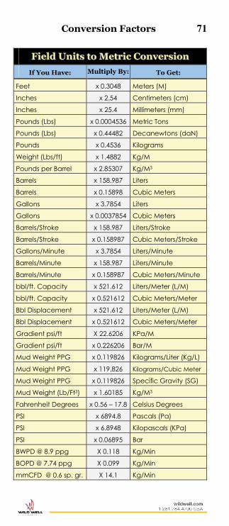
Conversion Factors 71
FFiieelldd UUnniittss ttoo MMeettrriicc CCoonnvveerrssiioonn
If You Have: Multiply By: To Get:
Feet x 0.3048 Meters (M)
Inches x 2.54 Centimeters (cm)
Inches x 25.4 Millimeters (mm)
Pounds (Lbs) x 0.0004536 Metric Tons
Pounds (Lbs) x 0.44482 Decanewtons (daN)
Pounds x 0.4536 Kilograms
Weight (Lbs/ft) x 1.4882 Kg/M
Pounds per Barrel x 2.85307 Kg/M3
Barrels x 158.987 Liters
Barrels x 0.15898 Cubic Meters
Gallons x 3.7854 Liters
Gallons x 0.0037854 Cubic Meters
Barrels/Stroke x 158.987 Liters/Stroke
Barrels/Stroke x 0.158987 Cubic Meters/Stroke
Gallons/Minute x 3.7854 Liters/Minute
Barrels/Minute x 158.987 Liters/Minute
Barrels/Minute x 0.158987 Cubic Meters/Minute
bbl/ft. Capacity x 521.612 Liters/Meter (L/M)
bbl/ft. Capacity x 0.521612 Cubic Meters/Meter
Bbl Displacement x 521.612 Liters/Meter (L/M)
Bbl Displacement x 0.521612 Cubic Meters/Meter
Gradient psi/ft X 22.6206 KPa/M
Gradient psi/ft x 0.226206 Bar/M
Mud Weight PPG x 0.119826 Kilograms/Liter (Kg/L)
Mud Weight PPG x 119.826 Kilograms/Cubic Meter
Mud Weight PPG x 0.119826 Specific Gravity (SG)
Mud Weight (Lb/Ft3) x 1.60185 Kg/M3
Fahrenheit Degrees x 0.56 – 17.8 Celsius Degrees
PSI x 6894.8 Pascals (Pa)
PSI x 6.8948 Kilopascals (KPa)
PSI x 0.06895 Bar
BWPD @ 8.9 ppg X 0.118 Kg/Min
BOPD @ 7.74 ppg X 0.099 Kg/Min
mmCFD @ 0.6 sp. gr. X 14.1 Kg/Min

72 Conversion Factors
MMeettrriicc ttoo FFiieelldd UUnniittss CCoonnvveerrssiioonn
If You Have: Multiply By: To Get:
Meters (m) x 3.2808 Feet
Centimeters (cm) x 0.3937 Inches
Millimeters (mm) x 0.03937 Inches
Metric Tons x 2204.6 Pounds (Lbs)
Decanewtons (daN) x 2.2481 Pounds (Lbs)
Kilograms x 2.2046 Pounds
Kg/m x 0.67196 Weight (Lbs/Ft)
Kg/m3 x 0.3505 Pounds per Barrel
Liters x 0.00629 Barrels
Cubic Meters x 6.2898 Barrels
Liters x 0.2642 Gallons
Cubic Meters x 264.173 Gallons
Liters/Stroke x 0.00629 Barrels/Stroke
Cubic Meters/Stroke x 6.2898 Barrels/Stroke
Liters/Minute x 0.2642 Gallons/Minute
Liters/Minute x 0.00629 Barrels/Minute
Cubic Meters/Minute x 6.2898 Barrels/Minute
Liters/Meter (l/m) x 0.0019171 BBL/Ft. Capacity
Cubic Meters/Meter x 1.917 BBL/Ft. Capacity
Liters/Meter (l/m) x 0.0019171 BBL Displacement
Cubic Meters/Meter x 1.9171 BBL Displacement
KPa/m x 0.044207 Gradient PSI/Ft
Bar/m x 4.4207 Gradient PSI/Ft
Kilograms/Liter (Kg/L) x 8.3454 Mud Weight PPG Kilograms/Cubic Meter
x 0.0083454 Mud Weight PPG
Specific Gravity (SG) x 8.3454 Mud Weight PPG
Kg/m3 x 6.24279 Mud Weight Lb/Ft3)
Celsius Degrees x 1.8 + 32 Fahrenheit Degrees
Pascals (Pa) x 0.000145 PSI
Kilopascals (KPa) x 0.14504 PSI
Bar x 14.50377 PSI
Kg/Minute X 8.475 BWPD @ 8.9 ppg
Kg/Minute X 10.105 BOPD @ 7.74 ppg
Kg/Minute X 0.071 mmCFD @ 0.6 sp.gr.
Notes & Calculations 73
74 Notes & Calculations

Notes & Calculations 75

76 Notes & Calculations

As the leading provider of comprehensive emergency response and resolution, prevention, and operational services for the oil and gas industry, Wild Well offers innovative solutions to complex issues. No other company on earth can claim a more experienced team, more jobs successfully completed, or more industry personnel trained each year.
Consider it covered. When it’s under Wild Well.
EMERGENCY: 1.281.784.4700
Wild WellWorld Headquarters1.281.784.4700 wildwell.com


