
Technical�training.Product�information.
BMW�Service
F82�GTS�Complete�Vehicle
General�informationSymbols�used
The�following�symbol�is�used�in�this�document�to�facilitate�better�comprehension�or�to�draw�attentionto�very�important�information:
Contains�important�safety�information�and�information�that�needs�to�be�observed�strictly�in�order�toguarantee�the�smooth�operation�of�the�system.
Information�status�and�national-market�versions
BMW�Group�vehicles�meet�the�requirements�of�the�highest�safety�and�quality�standards.�Changesin�requirements�for�environmental�protection,�customer�benefits�and�design�render�necessarycontinuous�development�of�systems�and�components.�Consequently,�there�may�be�discrepanciesbetween�the�contents�of�this�document�and�the�vehicles�available�in�the�training�course.
This�document�basically�relates�to�the�European�version�of�left�hand�drive�vehicles.�Some�operatingelements�or�components�are�arranged�differently�in�right-hand�drive�vehicles�than�shown�in�thegraphics�in�this�document.�Further�differences�may�arise�as�the�result�of�the�equipment�specification�inspecific�markets�or�countries.
Additional�sources�of�information
Further�information�on�the�individual�topics�can�be�found�in�the�following:
• Owner's�Handbook• Integrated�Service�Technical�Application.
Contact:�[email protected]
©2015�BMW�AG,�Munich
Reprints�of�this�publication�or�its�parts�require�the�written�approval�of�BMW�AG,�Munich.
The�information�contained�in�this�document�forms�an�integral�part�of�the�technical�training�of�theBMW�Group�and�is�intended�for�the�trainer�and�participants�in�the�seminar.�Refer�to�the�latest�relevantinformation�systems�of�the�BMW�Group�for�any�changes/additions�to�the�technical�data.
Information�status:�October�2015Technical�Training
F82�GTS�Complete�VehicleContents1. Introduction.............................................................................................................................................................................................................................................1
1.1. History......................................................................................................................................................................................................................................21.1.1. E30�M3�Sport�Evo�II........................................................................................................................................................21.1.2. E36�M3�GT.....................................................................................................................................................................................31.1.3. E46�M3�CSL................................................................................................................................................................................41.1.4. E92�M3�GTS................................................................................................................................................................................51.1.5. E90�M3�CRT............................................................................................................................................................................... 61.1.6. F82�M4�MotoGP�SAFETY�CAR....................................................................................................................7
1.2. Vehicle�fact�sheet�F82�M4�GTS.....................................................................................................................................................8
2. Technical�Data...............................................................................................................................................................................................................................10
3. Body..................................................................................................................................................................................................................................................................123.1. Bodyshell........................................................................................................................................................................................................................ 123.2. Exterior................................................................................................................................................................................................................................13
3.2.1. Front�view.....................................................................................................................................................................................133.2.2. Side�view.......................................................................................................................................................................................163.2.3. Rear�view.......................................................................................................................................................................................173.2.4. Exterior�colors....................................................................................................................................................................... 22
3.3. Interior..................................................................................................................................................................................................................................233.3.1. Driving�area�and�steering�wheel...............................................................................................................233.3.2. Seats�and�seat�belts...................................................................................................................................................263.3.3. Door�trim�panels� ..............................................................................................................................................................293.3.4. Rear�parcel�shelf................................................................................................................................................................293.3.5. Sound�insulation................................................................................................................................................................293.3.6. Roll�bar..............................................................................................................................................................................................30
4. Drive..................................................................................................................................................................................................................................................................314.1. S55B30T0�engine............................................................................................................................................................................................31
4.1.1. Engine�mechanics..........................................................................................................................................................314.1.2. Oil�supply......................................................................................................................................................................................324.1.3. Service�information.......................................................................................................................................................324.1.4. Water�injection......................................................................................................................................................................32
4.2. Engine�electrical�system........................................................................................................................................................................474.2.1. Engine�control.......................................................................................................................................................................47
4.3. Fuel�supply.................................................................................................................................................................................................................. 514.4. Exhaust�system.....................................................................................................................................................................................................514.5. M�DCT�Drivelogic..............................................................................................................................................................................................53
4.5.1. M�DCT�Drivelogic�and�MDrive....................................................................................................................544.5.2. Launch�Control....................................................................................................................................................................554.5.3. Wheelspin�start................................................................................................................................................................... 56
F82�GTS�Complete�VehicleContents
4.5.4. Emergency�gearbox�release...........................................................................................................................574.5.5. Service�information.......................................................................................................................................................57
4.6. Rear�axle�final�drive........................................................................................................................................................................................ 584.6.1. Active�M�differential.....................................................................................................................................................584.6.2. Service�information.......................................................................................................................................................59
5. Chassis�and�Suspension............................................................................................................................................................................................605.1. Front�axle�and�rear�axle........................................................................................................................................................................... 60
5.1.1. Front�axle.......................................................................................................................................................................................615.1.2. Rear�axle.........................................................................................................................................................................................63
5.2. Adjustable�high-performance�chassis�and�suspension........................................................................645.2.1. Stepless�lowering............................................................................................................................................................645.2.2. Rebound......................................................................................................................................................................................... 665.2.3. Compression�stage.......................................................................................................................................................68
5.3. Wheel�alignment.................................................................................................................................................................................................695.3.1. Axle�setting�data............................................................................................................................................................... 695.3.2. Procedure.....................................................................................................................................................................................69
5.4. Brakes.................................................................................................................................................................................................................................. 725.5. Wheels�and�tires.................................................................................................................................................................................................73
5.5.1. Wheels...............................................................................................................................................................................................745.5.2. Cup�tires.........................................................................................................................................................................................74
6. Vehicle�Electrical�System.........................................................................................................................................................................................786.1. Active�Sound�Design�ASD..................................................................................................................................................................786.2. Heating�and�air�conditioning�system..................................................................................................................................786.3. Radio�and�speaker�system.................................................................................................................................................................78
7. Information�for�Service.................................................................................................................................................................................................817.1. F82�M4�GTS.............................................................................................................................................................................................................817.2. Replacement�part�orders.......................................................................................................................................................................817.3. Body........................................................................................................................................................................................................................................817.4. Seat�belts.......................................................................................................................................................................................................................817.5. S55B30T0�engine............................................................................................................................................................................................827.6. Water� injection.......................................................................................................................................................................................................827.7. M�DCT.................................................................................................................................................................................................................................827.8. Launch�Control�and�wheelspin�start...................................................................................................................................837.9. Active�M�differential.......................................................................................................................................................................................837.10. Adjustable�high-performance�chassis�and�suspension........................................................................837.11. Wheel�alignment.................................................................................................................................................................................................847.12. Tires........................................................................................................................................................................................................................................84

F82�GTS�Complete�Vehicle1.�Introduction
1
For�customers�with�especially�high�performance�demands,�BMW�M�GmbH�now�offers�the�extremesports�car�successor�based�on�the�BMW�M4�Coupé,�the�BMW�M4�GTS.�Like�its�predecessor,�the�E92BMW�M3�GTS,�the�BMW�M4�GTS�is�also�suitable�for�driving�at�club�sport�events.�The�BMW�M4�GTSis�produced�by�the�BMW�M�GmbH�manufacturing�facility�and�is�offered�as�a�perfectly�matched�andindividually�produced�package.�The�modifications�for�club�sport�use�include�the�drive,�chassis�andsuspension�technology,�vehicle�electrical�system�as�well�as�exterior�and�interior�body�equipment.The�market�introduction�of�the�BMW�M4�GTS�will�take�place�in�March�2016.
With�its�exclusive�offering�for�motor�sports�enthusiasts,�BMW�M�GmbH�continues�a�tradition�that�wasalready�established�with�the�earlier�generations�of�the�BMW�M3.�The�outstanding�sporty�potential�ofthe�BMW�M4�Coupé�has�been�exploited�and�consistently�further�developed�once�more.�Customersbenefit�from�the�extensive�know-how�of�the�company�in�the�field�of�development�and�production�ofracing�vehicles.�Thank�to�targeted�modifications�to�improve�performance�and�safety,�the�BMW�M4GTS�is�ready�for�driving�on�the�race�track�in�club�sport�competition�and�at�the�same�time�offers�thepossibility�of�vehicle�type�approval�for�street�use.�The�driver�can�thus�make�his�way�to�the�race�trackin�his�own�sports�vehicle�or�can�also�use�the�car�to�drive�to�work.
This�BMW�Sports�Coupé�based�on�the�F82�is�intended�for�the�ECE,�US�and�Asian�markets.�Productionof�left�and�right-hand�drive�vehicles�is�planned.�The�first�vehicle�will�be�built�at�the�start�of�2016�andproduction�will�end�after�approx.�700�units�worldwide�are�produced.�The�vehicles�will�be�built�on�theproduction�installations�on�the�basis�of�the�F82�and�then�finished�and�fine-tuned�by�a�supplier�(EDAGEngineering�GmbH).
F82,�BMW�M4�GTS
Consistently�purist�design,�adjustable�aerodynamic�elements,�increased�performance�throughwater�injection�for�the�turbocharged�six-cylinder�high-revving�in-line�engine,�as�well�as�chassis�andsuspension�technology�designed�to�meet�the�demands�of�driving�on�the�race�track�mean�that�theBMW�M4�GTS�occupies�a�leading�position�among�high-performance�vehicles�designed�for�club�sportevents.
The�visual�differentiation�in�comparison�with�the�BMW�M4�Coupé�includes�exterior�componentsfinished�in�matt�black�such�as�the�BMW�kidney�grille�and�roof�strips�as�well�as�the�side�gill�elementsin�dark-anodized�chrome�on�the�BMW�M4�GTS�(BMW�M4�Coupé�in�chrome).
Only�the�differences�of�the�F82�M4�GTS�in�comparison�with�the�F82�M4�Coupé�will�be�described�here.

F82�GTS�Complete�Vehicle1.�Introduction
2
1.1.�History
1.1.1.�E30�M3�Sport�Evo�II1990
The�BMW�M3�Sport�Evo�II�wins�15�national�and�international�championships.�The�limited�productionrun�of�600�Evo�II�with�catalytic�converter�and�238�hp�(S14B25)�is�quickly�sold�out.
E30,�BMW�M3�Sport�Evo�II
F82�GTS�Complete�Vehicle1.�Introduction
3
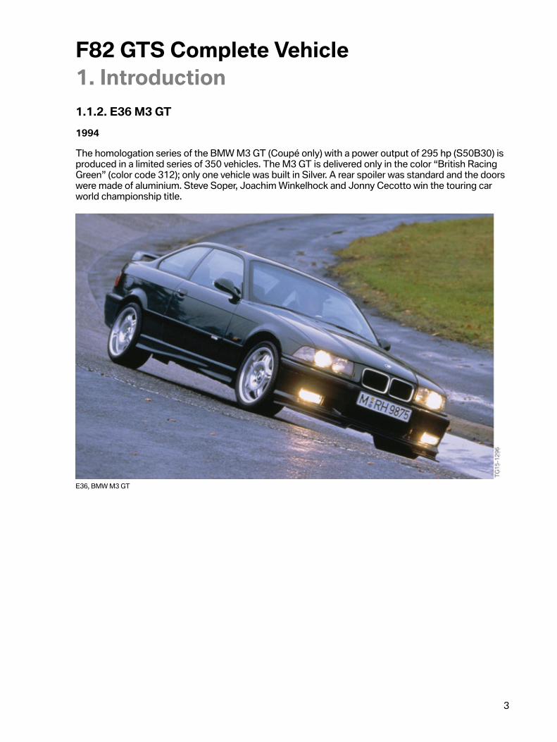
1.1.2.�E36�M3�GT1994
The�homologation�series�of�the�BMW�M3�GT�(Coupé�only)�with�a�power�output�of�295�hp�(S50B30)�isproduced�in�a�limited�series�of�350�vehicles.�The�M3�GT�is�delivered�only�in�the�color�“British�RacingGreen”�(color�code�312);�only�one�vehicle�was�built�in�Silver.�A�rear�spoiler�was�standard�and�the�doorswere�made�of�aluminium.�Steve�Soper,�Joachim�Winkelhock�and�Jonny�Cecotto�win�the�touring�carworld�championship�title.
E36,�BMW�M3�GT

F82�GTS�Complete�Vehicle1.�Introduction
4
1.1.3.�E46�M3�CSL2002
With�the�BMW�M3�CSL�with�360�hp�(S54B32HP)�produced�in�a�limited�series�of�1,383�units,�BMWM�shows�how�a�high-powered�vehicle�can�be�further�optimised�through�the�use�of�lightweightconstruction�materials�in�an�intelligent�lightweight�construction.�Features�available�here�for�the�firsttime�include�M�track�mode�(today�called�M�dynamic�mode),�SMG�Launch�Control�(automatic�upshiftsin�S�mode�shortly�before�maximum�engine�speed),�an�electronic�oil-level�check,�Michelin�Cup�tires�andthe�Run�Flat�Indicator�RPA.
E46,�BMW�M3�CSL

F82�GTS�Complete�Vehicle1.�Introduction
5
1.1.4.�E92�M3�GTS2010
As�a�low-volume�production�series�for�customers�who�take�part�in�club�sport�events,�BMW�M�GmbHoffered�the�M3�GTS.�The�extreme�sports�car�underwent�modifications�in�the�drive�and�chassis�andsuspension,�as�well�as�in�the�interior�equipment�and�the�body�in�order�to�meet�the�requirements�inclub�sports.�The�power�of�the�high-speed�S65B44�was�raised�to�450�HP.
E92,�BMW�M3�GTS

F82�GTS�Complete�Vehicle1.�Introduction
6
1.1.5.�E90�M3�CRT2011
On�the�basis�of�the�E90�BMW�M3�Sedan,�M�GmbH�offered�the�BMW�M3�CRT�(Carbon�RacingTechnology)�from�2011.�On�the�BMW�M3�CRT,�as�previously�on�the�BMW�M3�GTS,�the�vehicle�weightwas�reduced�by�approx.�70�kg/154�lbs�compared�with�the�BMW�M3�by�the�use�of�carbon.�The�BMWM3�CRT�was�built�and�delivered�to�customers�as�a�small�series�of�only�67�vehicles.�The�power�data�ofthe�S65B44�corresponds�to�the�figures�of�the�E92�BMW�M3�GTS.
E90,�BMW�M3�CRT

F82�GTS�Complete�Vehicle1.�Introduction
7
1.1.6.�F82�M4�MotoGP�SAFETY�CAR2015
The�BMW�M4�MotoGP�Safety�Car�was�built�in�2015�on�the�basis�of�the�F82.�This�MotoGP�Safety�Caralready�included�a�number�of�technologies�now�also�featured�in�the�F82�M4�GTS.
F82,�BMW�M4�MotoGP�SAFETY�CAR
The�BMW�M4�MotoGP�Safety�Car�already�included�the�following�F82�BMW�4�GTS�technologies:
• Front�splitter• Water�injection• Coilover�suspension• Rear�spoiler�made�of�carbon-fiber-reinforced�plastic• Exhaust�system�made�of�titanium�with�purist�exhaust�tailpipes�made�of�titanium
F82�GTS�Complete�Vehicle1.�Introduction
8
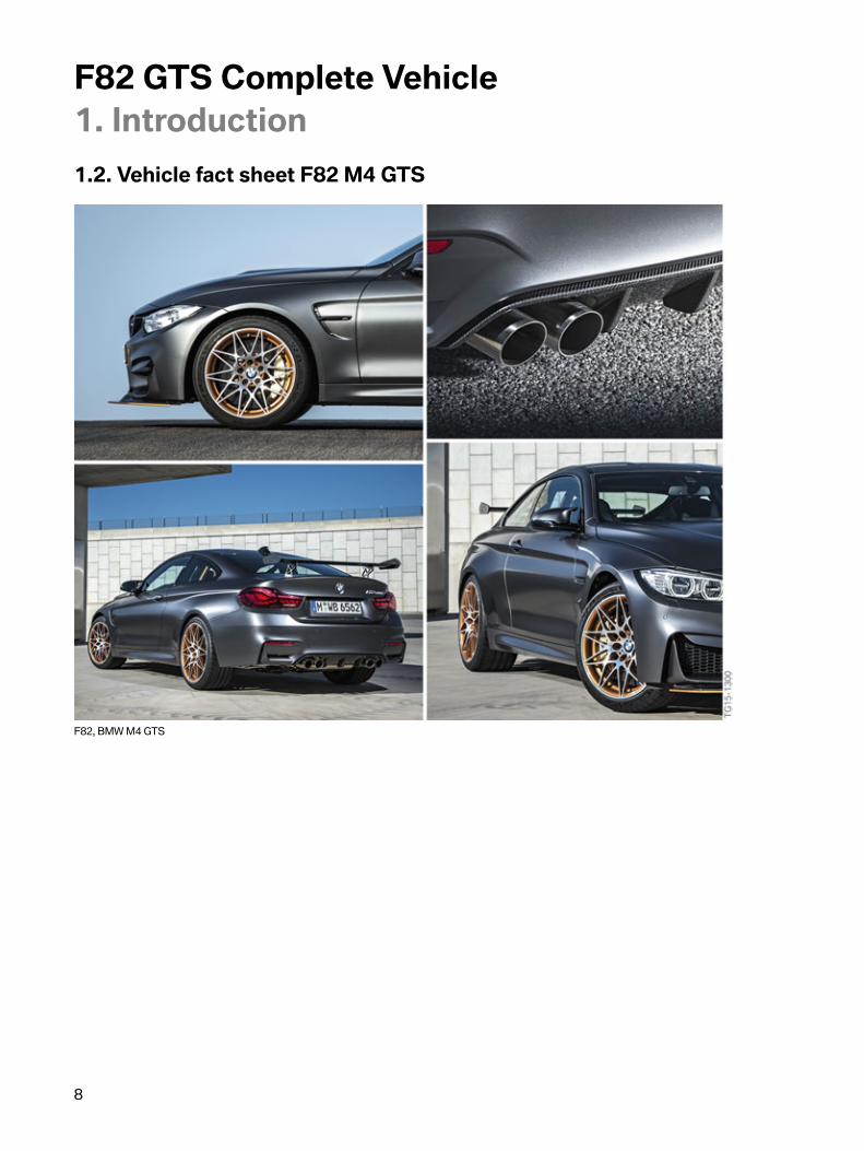
1.2.�Vehicle�fact�sheet�F82�M4�GTS
F82,�BMW�M4�GTS

F82�GTS�Complete�Vehicle1.�Introduction
9
• Design�and�Aerodynamics:�2-door�high-performance�sports�coupé�is�designed�forcustomers�who�want�to�take�part�in�club�sport�events.�M-specific�characteristics�in�front,�sideand�rear�area.�Unique�aerodynamic�design�in�front,�side�and�rear�area�and�vehicle�underbody.Aerodynamics�can�be�adapted�to�the�customer�depending�on�situation.�Consistent�lightweightconstruction�in�the�entire�interior�and�exterior�body�area.
• Engine/Transmission:�3-liter�6-cylinder�TVDI�engine�with�water�injection�for�increasedperformance.�Efficient,�with�even�more�powerful�and�more�spontaneous�linear�powerdevelopment.�Fuel�and�oil�supply�designed�for�maximum�g�loads�in�club�sport.�7-speed�Mdouble-clutch�transmission�with�Drivelogic.�Electronically�controlled�M�rear-axle�differentiallock.�Consistent�lightweight�construction�in�the�drive�area.
• Steering:�Direct�and�precise,�variable�M�Servotronic�(EPS)�with�Servotronic�support�(in�threestages).�M�steering�wheel�in�Alcantara�including�12�o'clock�marking,�M�shift�paddles�andMDrive�buttons.
• Chassis�and�Suspension/Chassis�and�Suspension�Dynamics�Design:�M�chassis�isstandard�equipment.�3-way�adjustment�by�the�customer�possible�for�adaptation�to�therespective�club�sport�circuits.�Club�tires�on�forged�19”�wheels�at�front�and�20”�wheels�at�rearas�standard.�Optimal�driving�precision�and�adapted�interplay�of�steering,�tires,�suspension�anddamping�action�according�to�the�customer's�wishes.�M�carbon�ceramic�brake�for�optimumbraking�power�on�the�race�track.
• Seating�Comfort:�Fully�adjustable�BMW�M�bucket�seats�with�three-point�seat�belts.

F82�GTS�Complete�Vehicle2.�Technical�Data
10
Designation E92�M3�GTS F82�M4�Coupé F82�M4�GTSYear 2010/2011 06.2014�– 2016Length�[mm]Width�[mm]Width�(mirrors)�[mm]Height�[mm]
4,6451,8041,9761,387
4,6871,8702,0141,383
4,6891,8702,0141,383
Seats 2 4 2Engine�type V8
S65B44M0R6
S55B30T0R6
S55B30T0Cubic�capacity�[cm³] 4,361 2,979 2,979Bore�[mm] 92 84.0 84.0Stroke�[mm] 82 89.6 89.6Power�[kW/HP]at�speed�[rpm]Max.�engine�speed
331/4448,3008,400
317/4255,500–7,300
368/4936,250
Torque�[Nm/lb-ft]at�speed�[rpm]
440/3253,750
550/4061,850–5,500
600/4434,000–5,500
Type�of�transmission M�DCT�DrivelogicGS7D36SG(+�1�liter�oil)
M�DCT�DrivelogicGS7D36BG�****
M�DCT�DrivelogicGS7D36BG
Fully�variableM�differential�lockRear-axle�ratio�[:1]
yes3.15:1
yesActive�M�differential
3.462:1
yesActive�M�differential
3.462:1Vehicle�curb�weight�[kg/lbs]
1,605/3,530 1,642/3,620 1,637/3,610
Gross�vehicle�weight[kg/lbs] 1,880/4,144 2,040/4,497 1,901/4,190Acceleration�0-100�km/h�[s]�(0–60�mph)
4.4 4.1�(3.9) 3.8�(3.6)
Vmax�[km/h/mph] 305**/190 250**/155280/174*** 305**/190
Chassis�andsuspension
Basis�E92�BMW�M3Rigidly�bolted
rear�axle�support,height-adjustablethreaded�chassis;
Adjustablecompressionand�rebound�ofthe�dampers.
Basis�F82�BMWM4�Coupé
Basis�F82�BMWM4�CoupéRigidly�bolted
rear�axle�support,height-adjustablethreaded�chassis;
Adjustablecompressionand�rebound�ofthe�dampers.
SteeringTurning�Circle�[m] 12.5 12.2 12.2
F82�GTS�Complete�Vehicle2.�Technical�Data
11
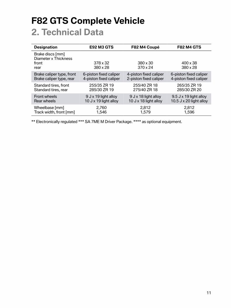
Designation E92�M3�GTS F82�M4�Coupé F82�M4�GTSBrake�discs�[mm]Diameter�x�Thicknessfrontrear
378�x�32380�x�28
380�x�30370�x�24
400�x�38380�x�28
Brake�caliper�type,�frontBrake�caliper�type,�rear
6-piston�fixed�caliper4-piston�fixed�caliper
4-piston�fixed�caliper2-piston�fixed�caliper
6-piston�fixed�caliper4-piston�fixed�caliper
Standard�tires,�frontStandard�tires,�rear
255/35�ZR�19285/30�ZR�19
255/40�ZR�18275/40�ZR�18
265/35�ZR�19285/30�ZR�20
Front�wheelsRear�wheels
9�J�x�19�light�alloy10�J�x�19�light�alloy
9�J�x�18�light�alloy10�J�x�18�light�alloy
9.5�J�x�19�light�alloy10.5�J�x�20�light�alloy
Wheelbase�[mm]Track�width,�front�[mm]
2,7601,546
2,8121,579
2,8121,596
**�Electronically�regulated�***�SA�7ME�M�Driver�Package.�****�as�optional�equipment.
F82�GTS�Complete�Vehicle3.�Body
12
3.1.�BodyshellThe�bodyshell�largely�corresponds�to�the�series�body�of�the�F82�M4�Coupé.�Special�mounting�pointsare�required�to�fit�the�GTS-specific�equipment.�These�include:
• Mounting�for�the�roll�bar�front�right�and�left• Mounting�for�the�roll�bar�at�rear�right�and�left• Heel�panels�for�mounting�the�rear�bench�cover�at�front
The�GTS-specific�mounts�are�welded�onto�the�bodyshell.

F82�GTS�Complete�Vehicle3.�Body
13
3.2.�Exterior
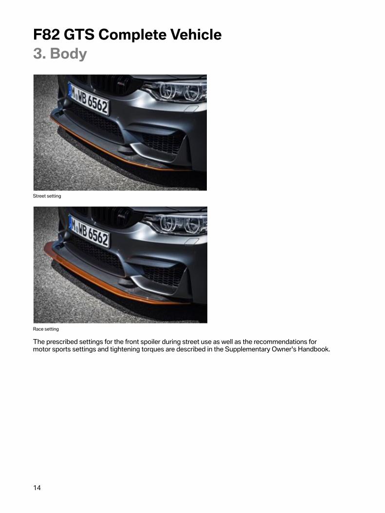
3.2.1.�Front�viewThe�bumper�panel�in�the�M-specific�design�corresponds�to�the�bumper�panel�of�the�F82�BMW�M4Coupé.�In�order�to�optimize�the�air�flow�and�downforce�adaptation�corresponding�to�demands,�theF82�M4�GTS�is�equipped�with�a�motor�sports-oriented�front�splitter�to�increase�the�downforce�in�thefront�area�of�the�vehicle.�The�front�splitter�is�weight-optimized�and�is�made�of�carbon-fiber-reinforcedplastic.�It�is�bolted�together�with�the�bumper�panel�in�exposed�carbon�look�and�is�always�provided�withan�"Acid�Orange"�outer�edge�regardless�of�the�chosen�vehicle�exterior�color.
The�frame�and�the�double-bridge�longitudinal�bars�of�the�BMW�M�kidney�grille�are�finished�in�high-gloss�black�as�standard�for�the�F82�M4�GTS�and�are�provided�with�the�M4�model�designation.
F82�GTS,�front�view
The�front�splitter�has�two�different�adjustment�positions�so�that�the�F82�M4�GTS�can�also�be�driven�onpublic�roads�with�sufficient�ground�clearance:
• Street�setting• Race�track�setting
F82�GTS�Complete�Vehicle3.�Body
14
Street�setting
Race�setting
The�prescribed�settings�for�the�front�spoiler�during�street�use�as�well�as�the�recommendations�formotor�sports�settings�and�tightening�torques�are�described�in�the�Supplementary�Owner's�Handbook.

F82�GTS�Complete�Vehicle3.�Body
15
Hood
The�hood�is�made�of�carbon-fiber-reinforced�plastic�on�the�F82�M4�GTS.
F82�GTS,�CFRP�hood
This�hood�structure�makes�it�possible�to�achieve�strength�properties�that�are�normally�only�possiblewith�a�steel�design.�However,�the�hood�of�the�F82�M4�GTS�is�made�of�carbon-fiber-reinforced�plasticand�weighs�25%�less�than�the�hood�made�of�aluminium�on�the�F82�M4.�The�CFRP�hood�thus�alsocontributes�to�the�lightweight�construction�concept�of�the�new�F82�M4�GTS.
The�hood�also�performs�engine�cooling�tasks�with�its�F82�M4�GTS-specific�openings�and�itsaerodynamic�design�additionally�supports�the�downforce�at�the�front�end.
F82�GTS�Complete�Vehicle3.�Body
16
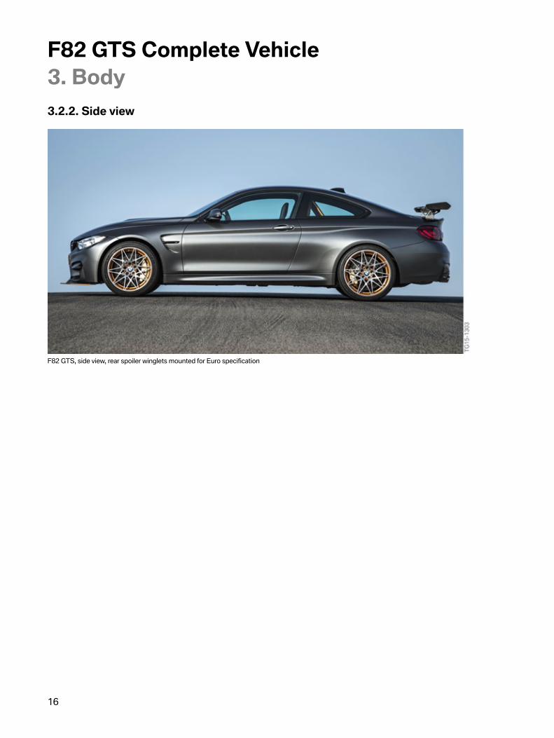
3.2.2.�Side�view
F82�GTS,�side�view,�rear�spoiler�winglets�mounted�for�Euro�specification

F82�GTS�Complete�Vehicle3.�Body
17
3.2.3.�Rear�view
F82�GTS,�rear�view
In�order�to�optimize�the�air�flow�and�permit�downforce,�the�F82�M4�GTS�is�equipped�with�motorsports-oriented�rear�wing�spoiler�as�well�as�a�diffuser�at�the�rear.�These�contribute�to�the�aerodynamicproperties�of�the�vehicle�to�match�the�specific�track�profile�and�other�conditions�when�it�is�used�on�therace�track.
F82�GTS�Complete�Vehicle3.�Body
18
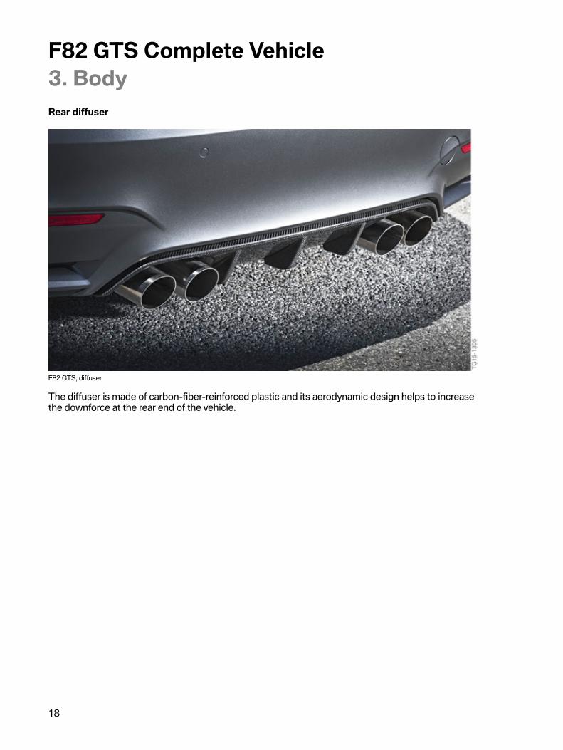
Rear�diffuser
F82�GTS,�diffuser
The�diffuser�is�made�of�carbon-fiber-reinforced�plastic�and�its�aerodynamic�design�helps�to�increasethe�downforce�at�the�rear�end�of�the�vehicle.
F82�GTS�Complete�Vehicle3.�Body
19
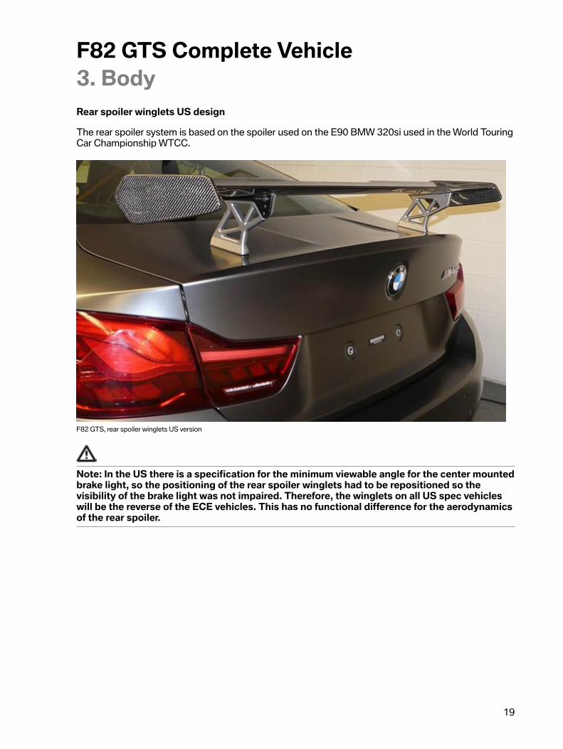
Rear�spoiler�winglets�US�design
The�rear�spoiler�system�is�based�on�the�spoiler�used�on�the�E90�BMW�320si�used�in�the�World�TouringCar�Championship�WTCC.
F82�GTS,�rear�spoiler�winglets�US�version
Note:�In�the�US�there�is�a�specification�for�the�minimum�viewable�angle�for�the�center�mountedbrake�light,�so�the�positioning�of�the�rear�spoiler�winglets�had�to�be�repositioned�so�thevisibility�of�the�brake�light�was�not�impaired.�Therefore,�the�winglets�on�all�US�spec�vehicleswill�be�the�reverse�of�the�ECE�vehicles.�This�has�no�functional�difference�for�the�aerodynamicsof�the�rear�spoiler.
F82�GTS�Complete�Vehicle3.�Body
20
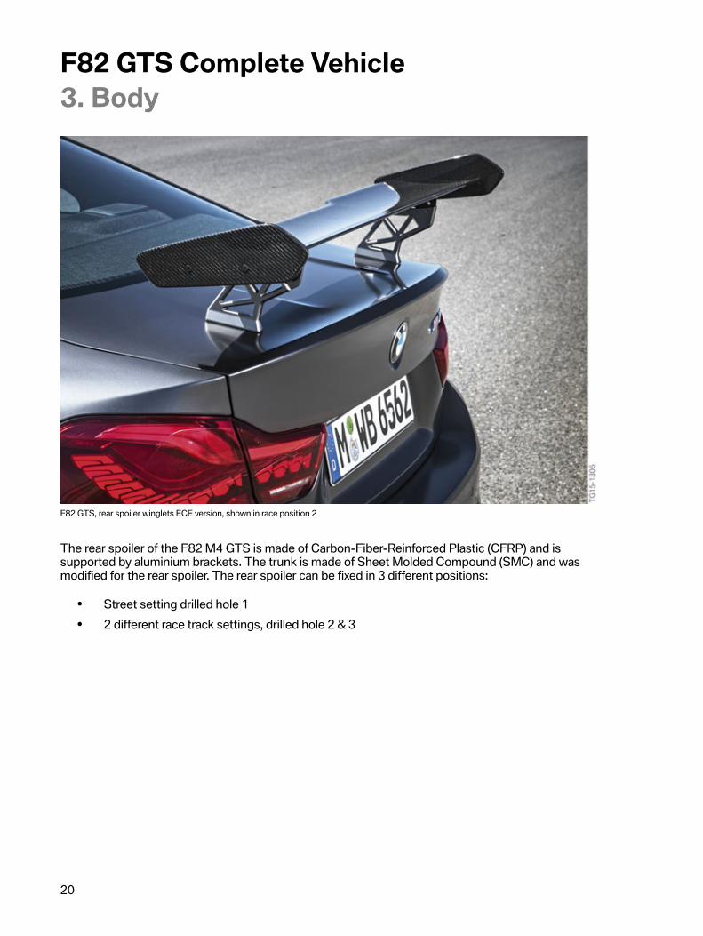
F82�GTS,�rear�spoiler�winglets�ECE�version,�shown�in�race�position�2
The�rear�spoiler�of�the�F82�M4�GTS�is�made�of�Carbon-Fiber-Reinforced�Plastic�(CFRP)�and�issupported�by�aluminium�brackets.�The�trunk�is�made�of�Sheet�Molded�Compound�(SMC)�and�wasmodified�for�the�rear�spoiler.�The�rear�spoiler�can�be�fixed�in�3�different�positions:
• Street�setting�drilled�hole�1• 2�different�race�track�settings,�drilled�hole�2�&�3
F82�GTS�Complete�Vehicle3.�Body
21
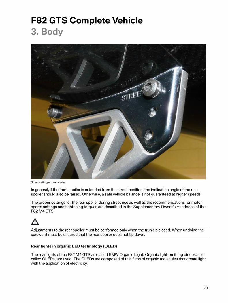
Street�setting�on�rear�spoiler
In�general,�if�the�front�spoiler�is�extended�from�the�street�position,�the�inclination�angle�of�the�rearspoiler�should�also�be�raised.�Otherwise,�a�safe�vehicle�balance�is�not�guaranteed�at�higher�speeds.
The�proper�settings�for�the�rear�spoiler�during�street�use�as�well�as�the�recommendations�for�motorsports�settings�and�tightening�torques�are�described�in�the�Supplementary�Owner's�Handbook�of�theF82�M4�GTS.
Adjustments�to�the�rear�spoiler�must�be�performed�only�when�the�trunk�is�closed.�When�undoing�thescrews,�it�must�be�ensured�that�the�rear�spoiler�does�not�tip�down.
Rear�lights�in�organic�LED�technology�(OLED)
The�rear�lights�of�the�F82�M4�GTS�are�called�BMW�Organic�Light.�Organic�light-emitting�diodes,�so-called�OLEDs,�are�used.�The�OLEDs�are�composed�of�thin�films�of�organic�molecules�that�create�lightwith�the�application�of�electricity.
F82�GTS�Complete�Vehicle3.�Body
22
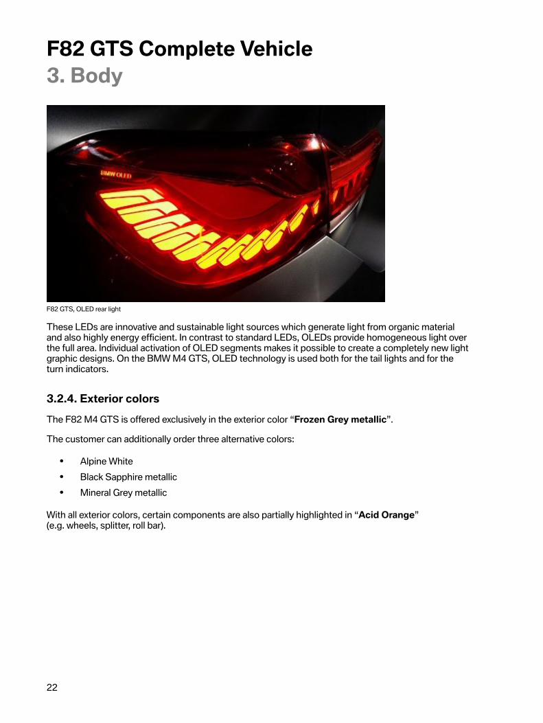
F82�GTS,�OLED�rear�light
These�LEDs�are�innovative�and�sustainable�light�sources�which�generate�light�from�organic�materialand�also�highly�energy�efficient.�In�contrast�to�standard�LEDs,�OLEDs�provide�homogeneous�light�overthe�full�area.�Individual�activation�of�OLED�segments�makes�it�possible�to�create�a�completely�new�lightgraphic�designs.�On�the�BMW�M4�GTS,�OLED�technology�is�used�both�for�the�tail�lights�and�for�theturn�indicators.
3.2.4.�Exterior�colorsThe�F82�M4�GTS�is�offered�exclusively�in�the�exterior�color�“Frozen�Grey�metallic”.
The�customer�can�additionally�order�three�alternative�colors:
• Alpine�White• Black�Sapphire�metallic• Mineral�Grey�metallic
With�all�exterior�colors,�certain�components�are�also�partially�highlighted�in�“Acid�Orange”(e.g.�wheels,�splitter,�roll�bar).
F82�GTS�Complete�Vehicle3.�Body
23
3.3.�Interior
3.3.1.�Driving�area�and�steering�wheelThe�vehicle�curb�weight�of�the�F82�M4�GTS�is�around�3,610�pounds.�For�this�reason,�lightweightdesign�was�consistently�used�for�many�components�in�the�interior.�Unnecessary�parts�such�as�the�rearbench�seat�was�removed�and�replaced�by�lightweight�covers.�The�individual�measures�are�described�inthe�chapter�"Interior".
M�driving�area
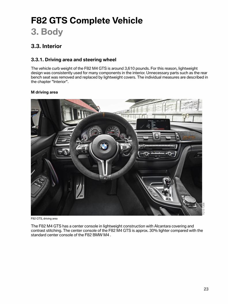
F82�GTS,�driving�area
The�F82�M4�GTS�has�a�center�console�in�lightweight�construction�with�Alcantara�covering�andcontrast�stitching.�The�center�console�of�the�F82�M4�GTS�is�approx.�30%�lighter�compared�with�thestandard�center�console�of�the�F82�BMW�M4�.

F82�GTS�Complete�Vehicle3.�Body
24
CFRP�instrument�panel
A�support�made�of�CFRP�material�is�used�for�the�first�time�to�support�the�instrument�panel�on�left-hand�drive�vehicles.�The�use�of�CFRP�made�it�possible�to�reduce�the�weight�of�the�instrument�panelin�the�F82�M4�GTS�compared�with�the�F82�BMW�M4�Coupé.
F82�GTS,�instrument�panel
F82�GTS�Complete�Vehicle3.�Body
25
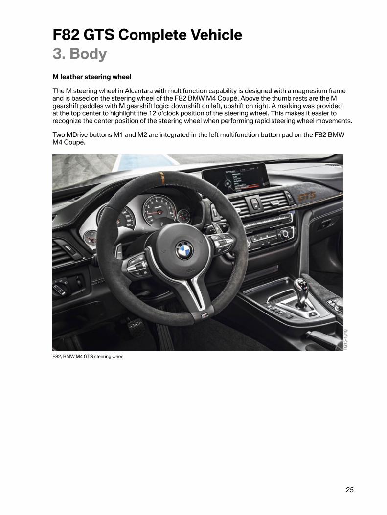
M�leather�steering�wheel
The�M�steering�wheel�in�Alcantara�with�multifunction�capability�is�designed�with�a�magnesium�frameand�is�based�on�the�steering�wheel�of�the�F82�BMW�M4�Coupé.�Above�the�thumb�rests�are�the�Mgearshift�paddles�with�M�gearshift�logic:�downshift�on�left,�upshift�on�right.�A�marking�was�providedat�the�top�center�to�highlight�the�12�o'clock�position�of�the�steering�wheel.�This�makes�it�easier�torecognize�the�center�position�of�the�steering�wheel�when�performing�rapid�steering�wheel�movements.
Two�MDrive�buttons�M1�and�M2�are�integrated�in�the�left�multifunction�button�pad�on�the�F82�BMWM4�Coupé.
F82,�BMW�M4�GTS�steering�wheel

F82�GTS�Complete�Vehicle3.�Body
26
3.3.2.�Seats�and�seat�beltsLight�weight�sport�bucket�seats�with�integrated�apertures�are�used�on�the�F82�M4�GTS.�Thesebucket�seats�offer�optimum�side�support�through�perfect�ergonomics�as�well�as�optimum�support�foracceleration�and�deceleration.
The�seat�covers�are�finished�in�Black�Extended�Merino�leather,�and�Alcantara.�Including�embroideredM�colors�on�the�head�rests.
F82�GTS,�seats
F82�GTS�Complete�Vehicle3.�Body
27
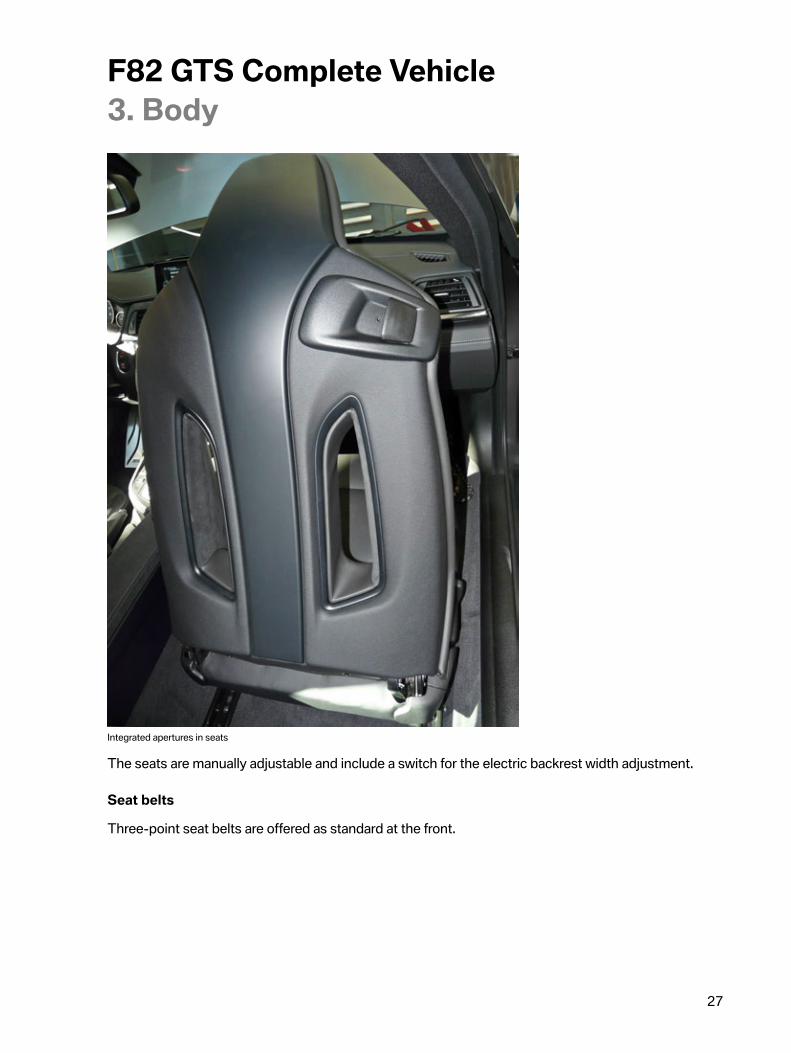
Integrated�apertures�in�seats
The�seats�are�manually�adjustable�and�include�a�switch�for�the�electric�backrest�width�adjustment.
Seat�belts
Three-point�seat�belts�are�offered�as�standard�at�the�front.

F82�GTS�Complete�Vehicle3.�Body
28
Seat�bench
A�rear�seat�bench�and�the�corresponding�seat�belts�were�removed.�Since�the�F82�M4�GTS�is�designedas�a�club�sport�vehicle,�the�rear�bench�is�not�needed.�The�following�components�are�used�instead:
• a�rear�partition�wall�is�made�of�Glass-Fiber�Reinforced�Plastic�(GFRP)�with�Alcantara�covering• the�rear�seat�bench�cover�is�made�of�GFRP�with�Alcantara�covering• a�special�floor�cover�in�the�rear�footwell
F82�GTS,�rear�bench�cover
These�measures�made�it�possible�to�reduce�the�weight�in�the�area�of�the�rear�seat�bench�by�40%�onthe�F82�M4�GTS�compared�with�the�F82�BMW�M4�Coupé.
F82�GTS�Complete�Vehicle3.�Body
29
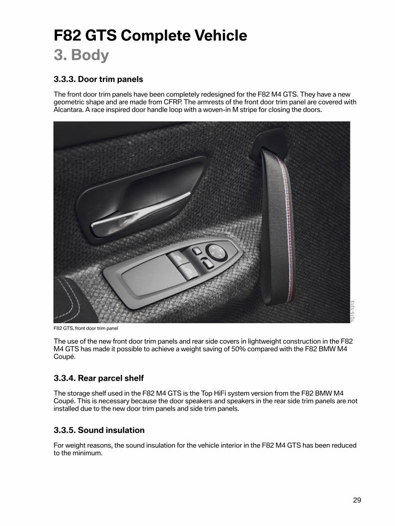
3.3.3.�Door�trim�panelsThe�front�door�trim�panels�have�been�completely�redesigned�for�the�F82�M4�GTS.�They�have�a�newgeometric�shape�and�are�made�from�CFRP.�The�armrests�of�the�front�door�trim�panel�are�covered�withAlcantara.�A�race�inspired�door�handle�loop�with�a�woven-in�M�stripe�for�closing�the�doors.
F82�GTS,�front�door�trim�panel
The�use�of�the�new�front�door�trim�panels�and�rear�side�covers�in�lightweight�construction�in�the�F82M4�GTS�has�made�it�possible�to�achieve�a�weight�saving�of�50%�compared�with�the�F82�BMW�M4Coupé.
3.3.4.�Rear�parcel�shelfThe�storage�shelf�used�in�the�F82�M4�GTS�is�the�Top�HiFi�system�version�from�the�F82�BMW�M4Coupé.�This�is�necessary�because�the�door�speakers�and�speakers�in�the�rear�side�trim�panels�are�notinstalled�due�to�the�new�door�trim�panels�and�side�trim�panels.
3.3.5.�Sound�insulationFor�weight�reasons,�the�sound�insulation�for�the�vehicle�interior�in�the�F82�M4�GTS�has�been�reducedto�the�minimum.

F82�GTS�Complete�Vehicle3.�Body
30
3.3.6.�Roll�bar
Roll�bar
A�roll�bar�is�used�which�is�installed�behind�the�B-pillar.�The�roll�bar�is�made�of�high-strength�steel�andis�provided�with�foam�padding�in�the�upper�area.�The�roll�bar�is�painted�in�Acid�Orange.�The�roll�bar�isbolted�to�the�floor�of�the�M4�GTS.
F82�GTS,�roll�bar�with�padding
F82�GTS�Complete�Vehicle4.�Drive
31
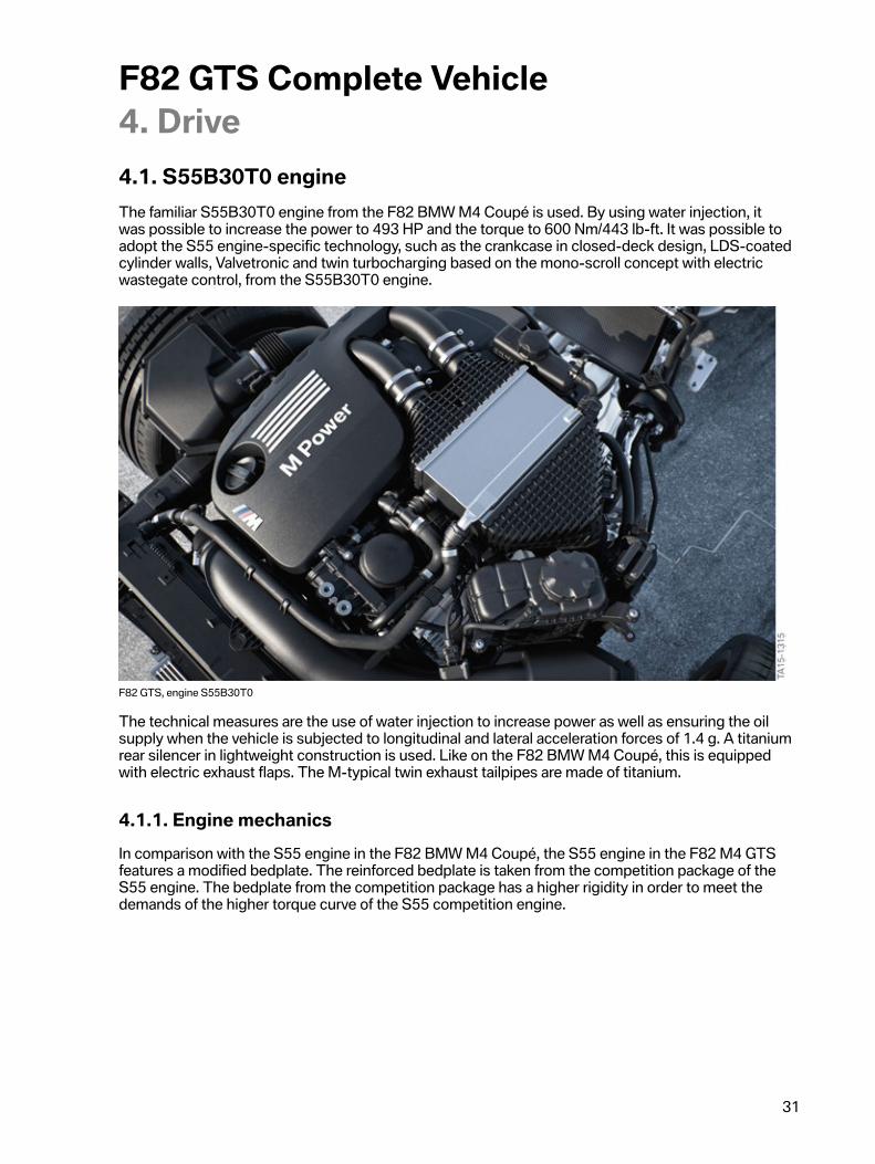
4.1.�S55B30T0�engineThe�familiar�S55B30T0�engine�from�the�F82�BMW�M4�Coupé�is�used.�By�using�water�injection,�itwas�possible�to�increase�the�power�to�493�HP�and�the�torque�to�600�Nm/443�lb-ft.�It�was�possible�toadopt�the�S55�engine-specific�technology,�such�as�the�crankcase�in�closed-deck�design,�LDS-coatedcylinder�walls,�Valvetronic�and�twin�turbocharging�based�on�the�mono-scroll�concept�with�electricwastegate�control,�from�the�S55B30T0�engine.
F82�GTS,�engine�S55B30T0
The�technical�measures�are�the�use�of�water�injection�to�increase�power�as�well�as�ensuring�the�oilsupply�when�the�vehicle�is�subjected�to�longitudinal�and�lateral�acceleration�forces�of�1.4�g.�A�titaniumrear�silencer�in�lightweight�construction�is�used.�Like�on�the�F82�BMW�M4�Coupé,�this�is�equippedwith�electric�exhaust�flaps.�The�M-typical�twin�exhaust�tailpipes�are�made�of�titanium.
4.1.1.�Engine�mechanicsIn�comparison�with�the�S55�engine�in�the�F82�BMW�M4�Coupé,�the�S55�engine�in�the�F82�M4�GTSfeatures�a�modified�bedplate.�The�reinforced�bedplate�is�taken�from�the�competition�package�of�theS55�engine.�The�bedplate�from�the�competition�package�has�a�higher�rigidity�in�order�to�meet�thedemands�of�the�higher�torque�curve�of�the�S55�competition�engine.

F82�GTS�Complete�Vehicle4.�Drive
32
4.1.2.�Oil�supplyThe�S55�engine�of�the�F82�M4�GTS�is�equipped�with�a�longer�oil-level�sensor.�This�is�necessary�sincethe�oil�quantity�of�the�S55�engine�in�the�F82�M4�GTS�was�increased�compared�with�the�S55�standardengine.�The�oil�quantity�in�the�oil�sump�in�the�S55�engine�of�the�F82�M4�GTS�is�6.5�liters�comparedwith�6.0�liters�in�the�S55�engine�for�the�F82�BMW�M4�Coupé.�It�was�necessary�to�increase�the�oilquantity�in�order�to�maintain�the�oil�supply�with�further�increased�g�forces�of�up�to�1.4�g�produced�bylongitudinal�and�transverse�acceleration�in�permanent�race�track�operation.�Since�the�oil-level�sensorused�in�the�S55�engine�for�the�F82�M4�GTS�is�restricted�by�the�available�installation�space,an�additional�shim�is�fitted�between�the�oil-level�sensor�and�oil�sump.
4.1.3.�Service�informationLike�on�the�F80/F82�and�F83,�the�engine�oil�is�currently�replaced�at�2,000�km�/�1200�miles�(running-in�check).�After�this,�the�running-in�check�must�be�reset�with�the�BMW�workshop�system�IntegratedService�Technical�Application,�ISTA.
Changed�engine�oil�fill�quantity�for�the�S55�engine�in�the�F82�M4�GTS.�The�fill�quantity�for�an�engineoil�change�with�filter�is�7.0�liters.�Engine�oil�fill�quantity�without�filter�exchange�is�6.5�liters.
The�current�information�and�specifications�in�the�Integrated�Service�Technical�Application�(ISTA)�mustbe�observed.
4.1.4.�Water�injection
Background
In�the�middle�of�the�1930’s�and�at�the�start�of�the�1940’s�in�the�last�century,�various�attempts�werealready�being�made�in�the�field�of�aeronautics�to�achieve�a�simple�and�effective�increase�in�theperformance�of�combustion�engines�through�turbocharging�which�could�be�implemented�quickly�ondemand�when�requested�by�the�pilot.�It�was�possible�to�effectively�meet�this�requirement�by�means�ofwater�injection.�Since�water�as�a�medium�also�contains�bound�oxygen�and�helps�cool�the�combustionchamber,�the�use�of�water�permits�the�charge�to�be�increased�by�the�charging�pressure�in�the�cylinderso�that�more�power�can�be�generated�in�a�combustion�engine.�The�targeted�injection�of�water,�whichcan�also�be�mixed�with�alcohol,�made�it�possible�to�achieve�a�short-term�increase�in�the�output�powerof�the�combustion�engines�by�over�40%�from�a�certain�charging�pressure.�This�was�necessary�inparticular�when�the�aircraft�was�climbing�or�flying�at�a�high�altitude�where�there�was�already�low�airpressure.�The�targeted�injection�of�water�or�water�mixture�into�the�combustion�engine�then�made�itpossible�for�the�pilot�to�achieve�a�short-term�increase�in�power.
After�this,�water�injection�was�used�only�very�rarely�for�many�decades,�until�it�was�again�discovered�inthe�1980’s�of�the�last�century�as�a�way�of�achieving�a�short-term�increase�in�power�in�Formula�1�cars.This�method�is�still�used�today�in�motor�sports.

F82�GTS�Complete�Vehicle4.�Drive
33
Function
The�distilled�water�(referred�to�as�"water"�below)�is�carried�in�a�separate�supply�tank�in�the�vehicle.At�a�certain�operating�point�(e.g.�charging�pressure,�load,�engine�speed),�the�water�is�drawn�in�fromthe�supply�tank�by�a�pump.�The�drawn�in�water�is�delivered�via�a�line�to�one�or�more�water�injectors.The�water�injectors,�which�can�be�installed�in�the�intake�plenum�for�the�intake�air,�inject�finely�atomizedwater�so�that�it�can�be�supplied�via�the�intake�channels�to�the�combustion�chamber.
With�water�injection,�the�engineers�exploit�the�physical�property�of�water�whereby�it�takes�the�energyrequired�for�evaporation�from�the�surrounding�area.�When�the�water�is�injected�into�the�intake�plenumas�a�fine�spray�mist,�its�evaporation�results�in�significant�cooling�of�the�intake�air�by�approx.�25�°C�/�77°F.�As�a�result,�the�final�compression�temperature�in�the�combustion�chamber�and�the�knock�tendencyis�reduced.�This�means�that�the�turbo�engine�can�be�operated�with�a�higher�charging�pressure�andearlier�ignition�point.
Advantages
• Efficiency:�Cooling�by�means�of�water�injection�makes�it�possible�to�achieve�a�reduction�incombustion�temperature�in�high�load�ranges.�This�permits�a�homogeneous�fuel-air�mixtureand�increased�efficiency�at�full�load.
• Emission�behavior:�Lower�combustion�temperatures�reduce�the�production�of�pollutants,particularly�nitrogen�oxides�(NOx).
• Reduced�knock�tendency:�The�risk�of�uncontrolled�combustion�(so-called�knocking)is�reduced�by�the�reduction�in�combustion�temperature.
• Higher�compression:�A�lower�knock�tendency�makes�it�possible�to�increase�thecompression.�This�results�in�optimized�efficiency�also�in�the�upper�partial�load�range.
• Dynamic:�An�earlier�ignition�point�and�higher�charging�pressure�increase�the�engine�powerand�torque�by�up�to�ten�percent.�An�additional�increase�in�power�is�achieved�by�the�higheroxygen�content�in�cool�intake�air.
• Fuel�compatibility:�Optimized�power�output�even�when�using�fuel�with�a�lower�octanenumber�(RON�95).�Turbo�engines�with�direct�water�injection�can�be�used�worldwide.
• Thermal�load:�The�cooling�effect�of�water�injection�reduces�temperature�influences�on�thepistons,�valves,�catalytic�converter�and�turbocharger.

F82�GTS�Complete�Vehicle4.�Drive
34
F82�GTS,�operating�principle�of�water�injection
Index ExplanationA Engine�under�low�loadB Engine�under�medium�loadC Engine�under�high�loadD Engine�under�high�load�with�activated�water�injection
F82�GTS�Complete�Vehicle4.�Drive
35
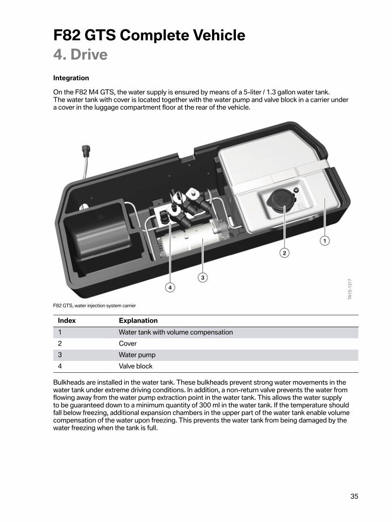
Integration
On�the�F82�M4�GTS,�the�water�supply�is�ensured�by�means�of�a�5-liter�/�1.3�gallon�water�tank.The�water�tank�with�cover�is�located�together�with�the�water�pump�and�valve�block�in�a�carrier�undera�cover�in�the�luggage�compartment�floor�at�the�rear�of�the�vehicle.
F82�GTS,�water�injection�system�carrier
Index Explanation1 Water�tank�with�volume�compensation2 Cover3 Water�pump4 Valve�block
Bulkheads�are�installed�in�the�water�tank.�These�bulkheads�prevent�strong�water�movements�in�thewater�tank�under�extreme�driving�conditions.�In�addition,�a�non-return�valve�prevents�the�water�fromflowing�away�from�the�water�pump�extraction�point�in�the�water�tank.�This�allows�the�water�supplyto�be�guaranteed�down�to�a�minimum�quantity�of�300�ml�in�the�water�tank.�If�the�temperature�shouldfall�below�freezing,�additional�expansion�chambers�in�the�upper�part�of�the�water�tank�enable�volumecompensation�of�the�water�upon�freezing.�This�prevents�the�water�tank�from�being�damaged�by�thewater�freezing�when�the�tank�is�full.
F82�GTS�Complete�Vehicle4.�Drive
36
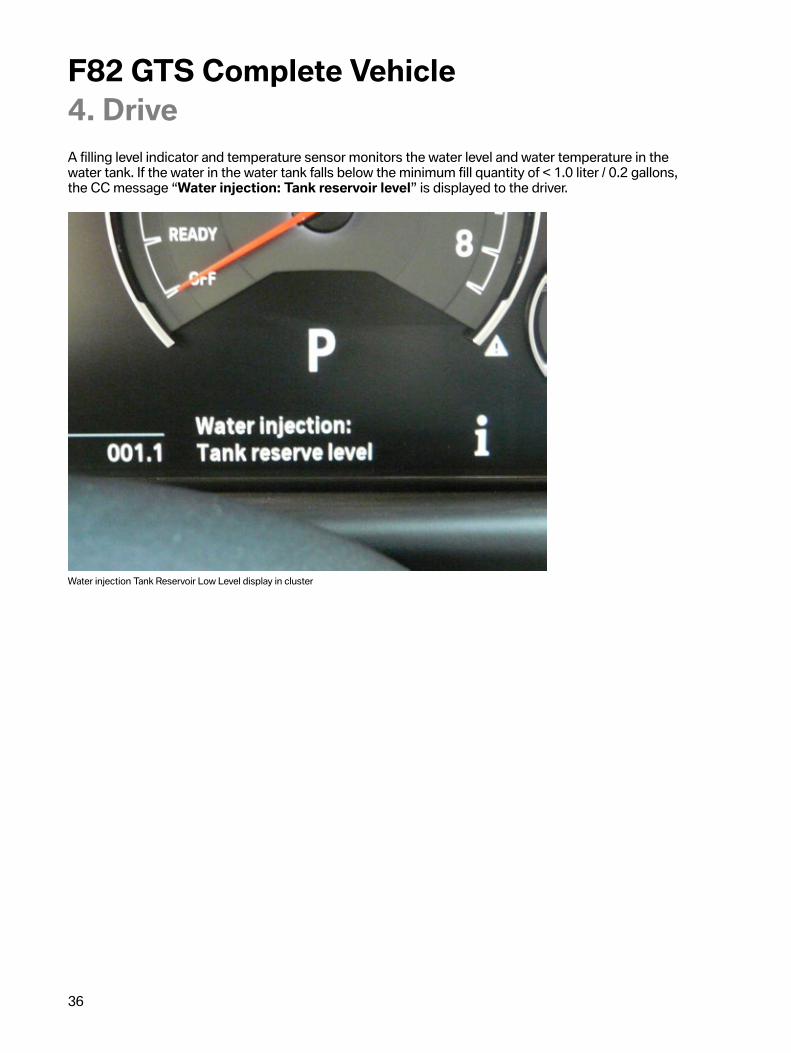
A�filling�level�indicator�and�temperature�sensor�monitors�the�water�level�and�water�temperature�in�thewater�tank.�If�the�water�in�the�water�tank�falls�below�the�minimum�fill�quantity�of�<�1.0�liter�/�0.2�gallons,the�CC�message�“Water�injection:�Tank�reservoir�level”�is�displayed�to�the�driver.
Water�injection�Tank�Reservoir�Low�Level�display�in�cluster

F82�GTS�Complete�Vehicle4.�Drive
37
Water�injection�is�no�longer�available�if�the�water�level�in�the�storage�tank�drops�below�the�minimumlevel�of�300�ml�/�10�ounces.�The�engine�power�will�then�be�lowered�to�the�standard�power�of�the�S55engine�along�with�a�check�control�message�in�the�cluster.
The�water�is�supplied�from�the�pump�to�the�water�injectors�by�a�line�that�is�routed�in�the�underbody�ofthe�F82�M4�GTS.�Three�water�injectors�are�installed�in�the�intake�air�plenum.�These�injectors�atomizethe�water�in�the�intake�air�plenum�that�is�mixed�with�air�that�enters�the�combustion�chamber,�there�isone�injector�for�every�2�cylinders.
F82�GTS,�components�for�water�injection�in�engine�compartment
Index Explanation1 Water�injectors2 Supply�line3 Intake�plenum
A�pump�generates�the�required�pressure.�A�valve�block�performs�water�distribution�to�the�waterinjectors�and�back�to�the�water�tank.�A�pressure�sensor�in�the�feed�line�in�the�valve�block�monitorsthe�pressure�in�the�system.

F82�GTS�Complete�Vehicle4.�Drive
38
F82�GTS,�pump�with�valve�block�for�water�injection
Index Explanation1 Water�pump2 Pressure�line3 Valve�block4 Pressure�sensor5 3/2-way�valve�26 3/2-way�valve�17 Shutoff�valve8 Intake�pipe

F82�GTS�Complete�Vehicle4.�Drive
39
The�valve�block�for�water�injection�contains�two�3/2-way�valves�which�control�the�water�flow�to�thewater�injectors�and�back�to�the�water�tank.�The�two�valves�are�required�since�the�running�direction�ofthe�water�pump�cannot�be�reversed.�The�flow�direction�of�the�water�is�therefore�controlled�by�means�ofthe�two�3/2-way�valves.
The�water�pump,�shutoff�valve�and�3/2-way�valves�are�activated�via�two�electric�relays,�which�arecorrespondingly�activated�by�the�DME.
The�shutoff�valve�ensures�that:
• the�water�tank�is�separated�from�the�system,�so�that�no�watercan�run�back�into�the�system�after�draining.
• the�pressure�in�the�system�can�be�maintained.
System�not�active
F82�GTS,�water�injection�not�active
Index Explanation1 DME2 Water�injectors3 Relay�for�3/2-way�valves4 Relay�for�water�pump/shutoff�valve5 Pressure�sensor6 Valve�block7 3/2-way�valve�2

F82�GTS�Complete�Vehicle4.�Drive
40
Index Explanation8 3/2-way�valve�19 Fine�filter�10�µm10 Shutoff�valve11 Water�pump�unit12 Water�pump13 Pressure-limiting�valve14 Water�tank15 Temperature�sensor/level�sensor
In�rest�state,�when�water�injection�is�not�active,�the�relays�for�controlling�the�pump,�shutoff�valve�and3/2-way�valves�are�not�activated�by�the�DME�and�are�de-energized.
Prerequisites
The�following�prerequisites�must�be�met�so�that�water�injection�can�be�activated:
• The�engine�must�be�running.• The�engine�must�be�at�operating�temperature.• The�ambient�temperature�must�be�>�5°C�/�41�°F.• The�water�tank�must�be�filled�with�"distilled�water".• The�fill�quantity�of�the�water�tank�must�be�>�300�ml�/�10�oz.
System�filling�and�pressure�maintenance
If�the�above�prerequisites�are�met,�the�system�is�filled�after�the�engine�is�started�until�a�pressure�of10�bar�is�reached.�When�requested�by�the�DME,�the�relay�for�the�water�pump�and�shutoff�valve�isenergized�by�the�DME.�The�water�pump�is�switched�on�and�the�shutoff�valve�is�opened.�The�waterpump�then�draws�in�water�from�the�water�tank�and�pumps�it�at�a�pressure�of�10�bar�to�the�waterinjectors�via�the�3/2-way�valves�and�the�pressure�sensor.�When�a�pressure�of�10�bar�has�been�reached,the�DME�switches�off�the�water�pump�and�closes�the�shutoff�valve.�The�shutoff�valve�maintains�thepressure�of�10�bar�in�the�system.

F82�GTS�Complete�Vehicle4.�Drive
41
F82�GTS,�water�injection�system�filling/pressure�maintenance
Index Explanation1 DME2 Water�injectors3 Relay�for�3/2-way�valves4 Relay�for�water�pump/shutoff�valve5 Pressure�sensor6 Valve�block7 3/2-way�valve�28 3/2-way�valve�19 Fine�filter�10�µm10 Shutoff�valve11 Water�pump�unit12 Water�pump13 Pressure-limiting�valve14 Water�tank15 Temperature�sensor/level�sensor
F82�GTS�Complete�Vehicle4.�Drive
42
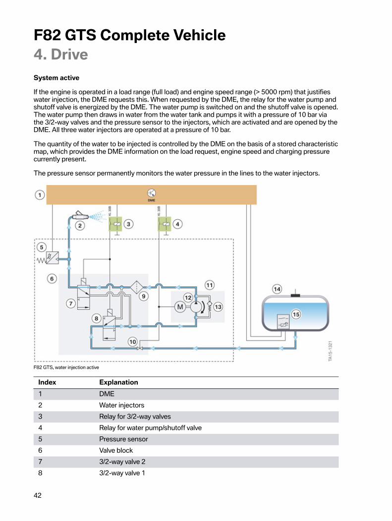
System�active
If�the�engine�is�operated�in�a�load�range�(full�load)�and�engine�speed�range�(>�5000�rpm)�that�justifieswater�injection,�the�DME�requests�this.�When�requested�by�the�DME,�the�relay�for�the�water�pump�andshutoff�valve�is�energized�by�the�DME.�The�water�pump�is�switched�on�and�the�shutoff�valve�is�opened.The�water�pump�then�draws�in�water�from�the�water�tank�and�pumps�it�with�a�pressure�of�10�bar�viathe�3/2-way�valves�and�the�pressure�sensor�to�the�injectors,�which�are�activated�and�are�opened�by�theDME.�All�three�water�injectors�are�operated�at�a�pressure�of�10�bar.
The�quantity�of�the�water�to�be�injected�is�controlled�by�the�DME�on�the�basis�of�a�stored�characteristicmap,�which�provides�the�DME�information�on�the�load�request,�engine�speed�and�charging�pressurecurrently�present.
The�pressure�sensor�permanently�monitors�the�water�pressure�in�the�lines�to�the�water�injectors.
F82�GTS,�water�injection�active
Index Explanation1 DME2 Water�injectors3 Relay�for�3/2-way�valves4 Relay�for�water�pump/shutoff�valve5 Pressure�sensor6 Valve�block7 3/2-way�valve�28 3/2-way�valve�1

F82�GTS�Complete�Vehicle4.�Drive
43
Index Explanation9 Fine�filter�10�µm10 Shutoff�valve11 Water�pump�unit12 Water�pump13 Pressure-limiting�valve14 Water�tank15 Temperature�sensor/level�sensor
If�water�injection�is�no�longer�required�at�the�request�of�the�DME,�the�water�pump�is�switched�off,along�with�the�shutoff�valve�and�water�injectors�by�the�relay.
The�shutoff�valve�holds�the�water�in�the�water�pump�and�in�the�valve�block�up�to�the�closed�waterinjectors.�This�means�that�it�is�not�necessary�to�fill�the�entire�system�again�when�water�injection�isactivated�once�more.
System�draining
The�system�is�drained�at�the�request�of�the�DME�if�the�engine�is�switched�off�or�if�the�ambienttemperature�falls�below�5�°C�/�41�°F.
When�requested�by�the�DME,�the�relay�for�the�water�pump�and�shutoff�valve�is�energized.�Since�therunning�direction�of�the�water�pump�cannot�be�reversed,�the�relay�for�the�two�3/2-way�valves�and�thewater�injectors�is�also�energized�at�the�same�time.
F82�GTS,�draining�the�water�injection�system

F82�GTS�Complete�Vehicle4.�Drive
44
Index Explanation1 DME2 Water�injectors3 Relay�for�3/2-way�valves4 Relay�for�water�pump/shutoff�valve5 Pressure�sensor6 Valve�block7 3/2-way�valve�28 3/2-way�valve�19 Fine�filter�10�µm10 Shutoff�valve11 Water�pump�unit12 Water�pump13 Pressure-limiting�valve14 Water�tank15 Temperature�sensor/level�sensor
As�a�result�of�the�changed�position�of�the�two�3/2-way�valves,�the�water�is�drawn�out�of�the�system�anddelivered�back�to�the�water�storage�tank�with�the�same�direction�of�rotation�of�the�water�pump.
When�the�engine�is�switched�off�and�the�water�injection�system�is�drained,�operating�noises�occurwhich�may�be�heard�by�the�customer.�These�operating�noises�cannot�be�avoided�due�to�the�operatingprinciple�of�the�system.
Component�protection
A�pressure�limiting�valve�limits�the�water�pressure�in�the�system�to�protect�all�components�in�the�eventof�a�malfunction�(e.g.�obstruction)�in�the�valve�block�or�in�the�downstream�components�such�as�linesand�water�injectors.

F82�GTS�Complete�Vehicle4.�Drive
45
F82�GTS,�component�protection�for�water�injection�system
Index Explanation1 DME2 Water�injectors3 Relay�for�3/2-way�valves4 Relay�for�water�pump/shutoff�valve5 Pressure�sensor6 Valve�block7 3/2-way�valve�28 3/2-way�valve�19 Fine�filter�10�µm10 Shutoff�valve11 Water�pump�unit12 Water�pump13 Pressure-limiting�valve14 Water�tank15 Temperature�sensor/level�sensor
F82�GTS�Complete�Vehicle4.�Drive
46
Water�consumption
The�water�consumption�depends�greatly�on�the�vehicle�operating�conditions�and�variescorrespondingly.�As�a�rule�of�thumb,�a�consumption�of�0.6�/�–�1�liter�per�100�km�or�0.15�gallons�–�0.26gallons�per�62�miles�can�be�expected�on�the�race�track.�In�the�case�of�dynamic�driving�(engine�speed>�5000�rpm�and�high�load)�in�everyday�use,�it�will�probably�be�necessary�to�top�up�with�water�at�onlyevery�5th�refuelling�operation.
Notes
When�filling�the�water�injection�system,�only�commercially�available�distilled�water�(demineralized�-decalcified)�must�be�used�for�the�F82�M4�GTS.�Other�fluids�or�mixtures�with�alcohol�is�not�approved�byBMW.
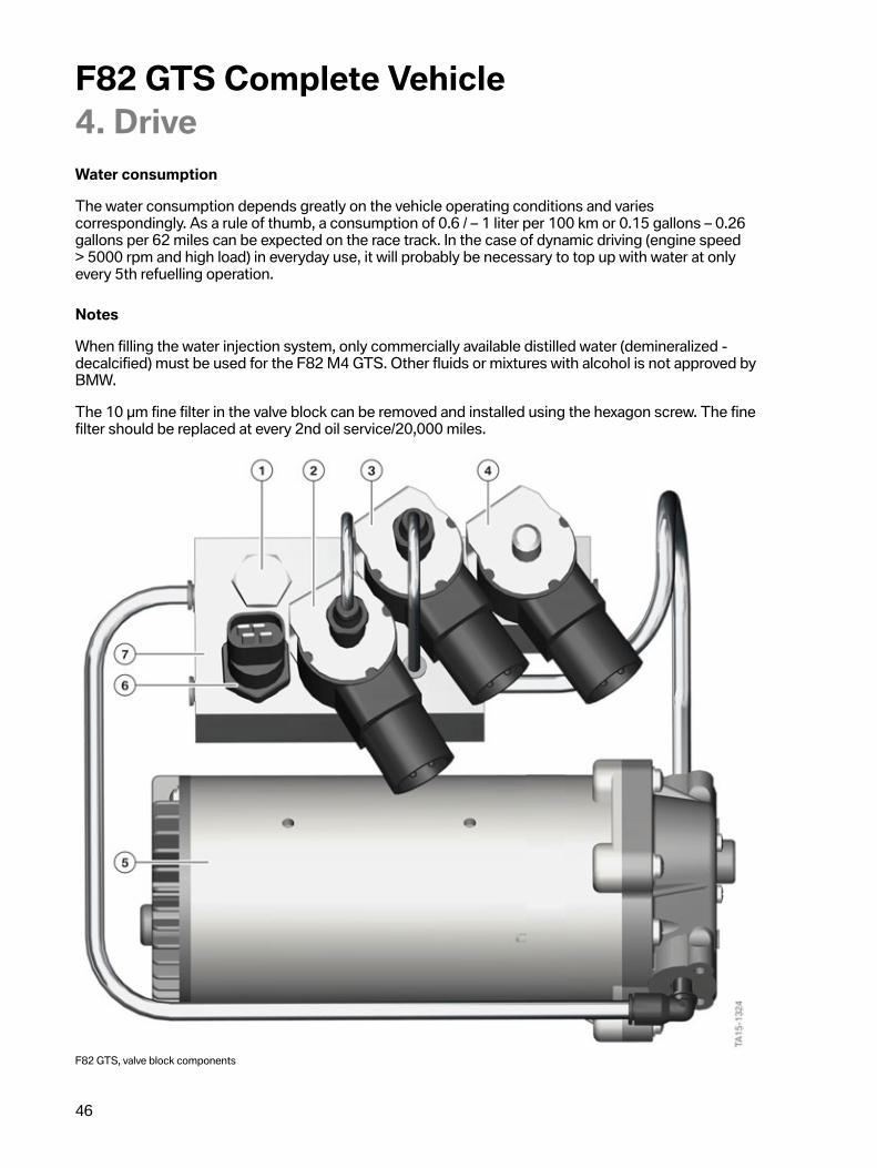
The�10�µm�fine�filter�in�the�valve�block�can�be�removed�and�installed�using�the�hexagon�screw.�The�finefilter�should�be�replaced�at�every�2nd�oil�service/20,000�miles.
F82�GTS,�valve�block�components

F82�GTS�Complete�Vehicle4.�Drive
47
Index Explanation1 Screw�for�fine�filter�10�µm2 3/2-way�valve�23 3/2-way�valve�14 Shutoff�valve5 Water�pump6 Pressure�sensor7 Valve�block
The�water�injection�system�can�be�diagnosed�via�the�DME.�The�current�information�and�specificationsin�the�documents�in�the�Integrated�Service�Technical�Application�(ISTA)�must�be�observed�in�eachcase.
Further�information�on�use�and�maintenance�of�the�water�injection�system�is�provided�in�theSupplementary�Owner's�Handbook.
4.2.�Engine�electrical�system
4.2.1.�Engine�controlAll�components�of�the�water�injection�system�are�integrated�in�the�engine�control.�Just�as�with�the�S55engine�of�the�production�vehicle�in�the�F82�BMW�M4�Coupé,�the�MEVD17.2.G�engine�control�is�usedfor�the�S55�engine�in�the�F82�M4�GTS.�When�developing�the�MEVD17.2.G,�the�hardware�was�alreadydesigned�to�meet�the�requirements�for�water�injection�in�the�F82�M4�GTS.

F82�GTS�Complete�Vehicle4.�Drive
48
F82�GTS,�system�wiring�diagram�MEVD17.2.G
F82�GTS�Complete�Vehicle4.�Drive
49
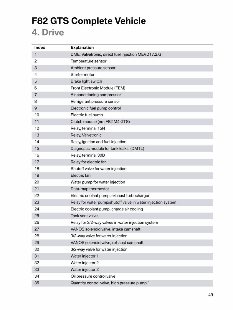
Index Explanation1 DME,�Valvetronic,�direct�fuel�injection�MEVD17.2.G2 Temperature�sensor3 Ambient�pressure�sensor4 Starter�motor5 Brake�light�switch6 Front�Electronic�Module�(FEM)7 Air�conditioning�compressor8 Refrigerant�pressure�sensor9 Electronic�fuel�pump�control10 Electric�fuel�pump11 Clutch�module�(not�F82�M4�GTS)12 Relay,�terminal�15N13 Relay,�Valvetronic14 Relay,�ignition�and�fuel�injection15 Diagnostic�module�for�tank�leaks,�(DMTL)16 Relay,�terminal�30B17 Relay�for�electric�fan18 Shutoff�valve�for�water�injection19 Electric�fan20 Water�pump�for�water�injection21 Data-map�thermostat22 Electric�coolant�pump,�exhaust�turbocharger23 Relay�for�water�pump/shutoff�valve�in�water�injection�system24 Electric�coolant�pump,�charge�air�cooling25 Tank�vent�valve26 Relay�for�3/2-way�valves�in�water�injection�system27 VANOS�solenoid�valve,�intake�camshaft28 3/2-way�valve�for�water�injection29 VANOS�solenoid�valve,�exhaust�camshaft30 3/2-way�valve�for�water�injection31 Water�injector�132 Water�injector�233 Water�injector�334 Oil�pressure�control�valve35 Quantity�control�valve,�high�pressure�pump�1

F82�GTS�Complete�Vehicle4.�Drive
50
Index Explanation36 Quantity�control�valve,�high�pressure�pump�237 Electrical�exhaust�flap,�cylinders�1�–�338 Electrical�exhaust�flap,�cylinders�4�–�639�–�44 Injectors45�–�50 Ignition�coils51 Engine�ventilation�heating52 Ground�connections53 Electrical�wastegate�valve�controller,�cylinders�1�–�354 Electrical�wastegate�valve�controller,�cylinders�4�–�655 Oxygen�sensor�after�catalytic�converter,�cylinders�1�–�356 Oxygen�sensor�after�catalytic�converter,�cylinders�4�–�657 Oxygen�sensor�before�catalytic�converter,�cylinders�1�–�358 Oxygen�sensor�before�catalytic�converter,�cylinders�4�–�659 Diagnostic�socket60 Fuel�low-pressure�sensor61 Intake-manifold�pressure�sensor�after�throttle�valve62 Rail�pressure�sensor63 Charge�air�temperature�and�pressure�sensor64 Knock�sensor,�cylinders�1–365 Hot�film�air�mass�meter,�cylinders�1�–�366 Knock�sensor,�cylinders�4-667 Hot�film�air�mass�meter,�cylinders�4�–�668 Gear�sensor�(not�F82�M4�GTS)69 Position�sensor,�high�pressure�pump70 Camshaft�sensor,�intake�camshaft71 Camshaft�sensor,�exhaust�camshaft72 Crankshaft�sensor73 Accelerator�pedal�module74 Level�sensor,�water�injection75 Electromotive�throttle�controller76 Pressure�sensor,�water�injection77 Coolant�temperature�sensor78 Oil�pressure�sensor79 Oil�temperature�sensor80 Temperature�sensor,�water�injection
F82�GTS�Complete�Vehicle4.�Drive
51
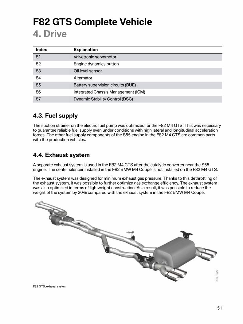
Index Explanation81 Valvetronic�servomotor82 Engine�dynamics�button83 Oil�level�sensor84 Alternator85 Battery�supervision�circuits�(BUE)86 Integrated�Chassis�Management�(ICM)87 Dynamic�Stability�Control�(DSC)
4.3.�Fuel�supplyThe�suction�strainer�on�the�electric�fuel�pump�was�optimized�for�the�F82�M4�GTS.�This�was�necessaryto�guarantee�reliable�fuel�supply�even�under�conditions�with�high�lateral�and�longitudinal�accelerationforces.�The�other�fuel�supply�components�of�the�S55�engine�in�the�F82�M4�GTS�are�common�partswith�the�production�vehicles.
4.4.�Exhaust�systemA�separate�exhaust�system�is�used�in�the�F82�M4�GTS�after�the�catalytic�converter�near�the�S55engine.�The�center�silencer�installed�in�the�F82�BMW�M4�Coupé�is�not�installed�on�the�F82�M4�GTS.
The�exhaust�system�was�designed�for�minimum�exhaust�gas�pressure.�Thanks�to�this�dethrottling�ofthe�exhaust�system,�it�was�possible�to�further�optimize�gas�exchange�efficiency.�The�exhaust�systemwas�also�optimized�in�terms�of�lightweight�construction.�As�a�result,�it�was�possible�to�reduce�theweight�of�the�system�by�20%�compared�with�the�exhaust�system�in�the�F82�BMW�M4�Coupé.
F82�GTS,�exhaust�system

F82�GTS�Complete�Vehicle4.�Drive
52
The�rear�silencer�and�the�M-typical�exhaust�tailpipes�are�made�of�weight-optimized�titanium�(systemsupplier�Eberspächer).�In�addition,�the�exhaust�tailpipes�have�a�purist�titanium�design�and�areembossed�with�the�"M"�designation.
The�electrical�exhaust�flaps�are�activated�directly�by�the�DME�by�a�pulse-width�modulated�signal.
F82�GTS,�rear�silencer
Index Explanation1 Bypass�pipe2 Electrical�exhaust�flap�actuator�(EAKS),�right3 Purist�titanium�twin�tailpipes4 Titanium�rear�silencer5 Electrical�exhaust�flap�actuator�(EAKS),�left

F82�GTS�Complete�Vehicle4.�Drive
53
The�exhaust�flap�can�be�opened�by�a�pulse-width�modulated�signal�of�10 %�and�closed�with�90 %pulse�width�modulation.�The�end�positions�are�the�mechanical�limit�positions�of�the�exhaust�flap.Intermediate�settings�are�not�intended.�The�exhaust�flap�can�be�moved�to�the�factory�position�for�theinstallation�by�a�pulse-width�modulated�signal�(PWM)�of�50 %.�In�order�to�ensure�that�the�desiredposition�is�held�even�if�the�electric�exhaust�flap�controller�is�not�actuated�for�a�long�period,�current�issupplied�again�every�320�s�+/-�10%.�This�acts�in�the�direction�of�the�limit�position�(duration�of�currentsupply:�50�ms�+/-�5�ms).
Functional�input�variables�for�the�calculation�of�the�exhaust�flap�setting�are:
• Vehicle�speed• Accelerator�pedal�angle• Position�of�driving�experience�switch• Engine�temperature• Gear�mode
There�is�a�always�a�flow�through�the�two�tailpipe�pairs�by�the�bypass�pipe�(1)�regardless�of�the�flapposition.�Therefore,�no�varying�blackening�of�the�two�tailpipe�pairs�occurs,�which�is�typical�of�vehicleswith�exhaust�flaps.�In�addition,�the�exhaust�flaps�in�the�tailpipe�pairs�are�not�visible�through�the�exhausttailpipes.
4.5.�M�DCT�DrivelogicFor�power�transmission,�the�F82�M4�GTS�uses�the�M�double-clutch�transmission�M�DCT�Drivelogicalso�optionally�available�for�the�F82�BMW�M4�Coupé�without�any�design�modifications.�The�shiftcharacteristic�of�the�7-speed�M�DCT�Drivelogic�was�made�even�more�suitable�for�motor�sports�drivingand�matched�specifically�to�the�F82�M4�GTS.
F82�GTS,�M�double-clutch�transmission�with�M�DCT�Drivelogic
F82�GTS�Complete�Vehicle4.�Drive
54
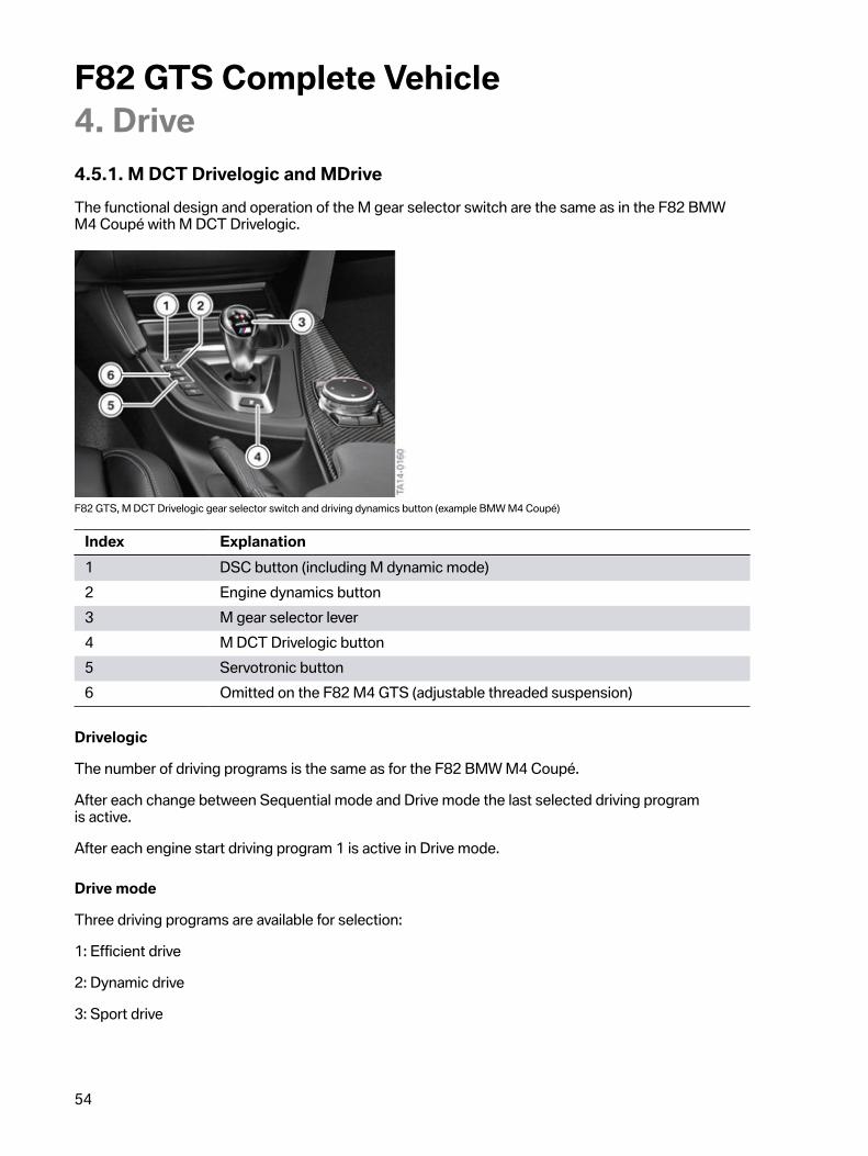
4.5.1.�M�DCT�Drivelogic�and�MDriveThe�functional�design�and�operation�of�the�M�gear�selector�switch�are�the�same�as�in�the�F82�BMWM4�Coupé�with�M�DCT�Drivelogic.
F82�GTS,�M�DCT�Drivelogic�gear�selector�switch�and�driving�dynamics�button�(example�BMW�M4�Coupé)
Index Explanation1 DSC�button�(including�M�dynamic�mode)2 Engine�dynamics�button3 M�gear�selector�lever4 M�DCT�Drivelogic�button5 Servotronic�button6 Omitted�on�the�F82�M4�GTS�(adjustable�threaded�suspension)
Drivelogic
The�number�of�driving�programs�is�the�same�as�for�the�F82�BMW�M4�Coupé.
After�each�change�between�Sequential�mode�and�Drive�mode�the�last�selected�driving�programis�active.
After�each�engine�start�driving�program�1�is�active�in�Drive�mode.
Drive�mode
Three�driving�programs�are�available�for�selection:
1:�Efficient�drive
2:�Dynamic�drive
3:�Sport�drive

F82�GTS�Complete�Vehicle4.�Drive
55
Sequential�mode
Three�driving�programs�are�also�available�here�for�selection:
1:�Comfortable�gear�shifts
2:�Sporty,�fast�gear�shifts
3:�Maximum�shift�speed�and�the�requirement�for�the�activation�of�the�launch�control
4.5.2.�Launch�ControlLaunch�Control�enables�optimal�acceleration�when�driving�off�on�a�smooth�roadway.
Launch�Control�should�generally�not�be�used�during�the�first�5,000�km�/�3100�miles�when�runningin�the�vehicle�(also�see�section�Driving�tips�in�the�Owner's�Handbook).
The�2,000 km�/�1200�miles�running-in�check�must�have�been�completed�and�reset/confirmed�withthe�Integrated�Service�Technical�Application�(ISTA)�(do�not�reset�via�the�instrument�cluster�servicefunction,�as�otherwise�the�launch�control�is�not�enabled).
Premature�wear�occurs�as�a�result�of�the�high�load�on�the�vehicle�components�when�using�LaunchControl.
Pre-configuring
Sequence Precondition/Action1. The�vehicle�must�be�stationary�with�the�engine�running�at�idle�speed�and
at�operating�temperature�(approx.�10 km�/�6�mile�warm-up�drive).2. Deactivate�Dynamic�Stability�Control�(DSC).3. The�Sequential�mode�and�the�third�Drivelogic�driving�program�are�selected.4. Slightly�press�and�hold�the�brake�pedal�with�your�left�foot.5. Fully�depress�the�accelerator�pedal�and�hold�in�position.6. A�flag�symbol�appears�in�the�M�instrument�cluster�(if�not,�check�instructions
and�steps�1�-�5).7. An�engine�speed�for�pulling�away�of�approx.�3,000�rpm�is�set.�This�can�be
modified�up�or�down�by�a�maximum�500�rpm�in�100�rpm�increments�usingthe�operating�elements�of�the�cruise�control.
8. Rapidly�release�the�brake�pedal�within�3�s.
F82�GTS�Complete�Vehicle4.�Drive
56
Effect
• The�Launch�Control�shifts�independently�up�to�the�maximum�speed�with�the�shortest�possibleshifting�times�and�shift�points�optimized�for�driving�performance�as�long�as�the�driver�keepsthe�accelerator�pedal�fully�depressed�and�a�time�limit�of�22�seconds�is�not�exceeded�foracceleration.
• The�start�flag�in�the�instrument�cluster�remains�active.
Automatic�deactivation
• The�driver�releases�(even�if�only�temporary)�the�accelerator�pedal�from�the�fully�depressedposition�during�acceleration�or�the�acceleration�phase�reaches�a�duration�of�22�seconds.
Activation�of�Launch�Control�is�not�possible�if�one�of�these�pre-configuration�conditions�is�not�met.
The�start�flag�goes�out�with�every�deactivation�and�the�automatic�forced�upshift�is�cancelled.
A�defined�distance�must�be�travelled�before�each�new�activation�of�Launch�Control.
Also�at�excessive�transmission�oil�temperature�(e.g.�repeat�Launch�Control�or�race-like�start),�activationis�blocked�up�until�an�acceptable�temperature�threshold�is�reached.
4.5.3.�Wheelspin�start
A�wheelspin�start�should�generally�not�be�used�during�the�first�5,000�km�/�3100�miles�when�runningin�the�vehicle�(see�also�the�chapter�Driving�tips�in�the�Owner's�Handbook).
The�2,000 km�/�1200�miles�running-in�check�must�have�been�completed�and�reset/confirmed�withthe�Integrated�Service�Technical�Application�(ISTA)�(do�not�reset�via�the�instrument�cluster�servicefunction,�as�otherwise�the�wheelspin�start�function�is�not�enabled).
Premature�wear�occurs�as�a�result�of�the�high�load�on�the�vehicle�components�when�using�thewheelspin�start�function.
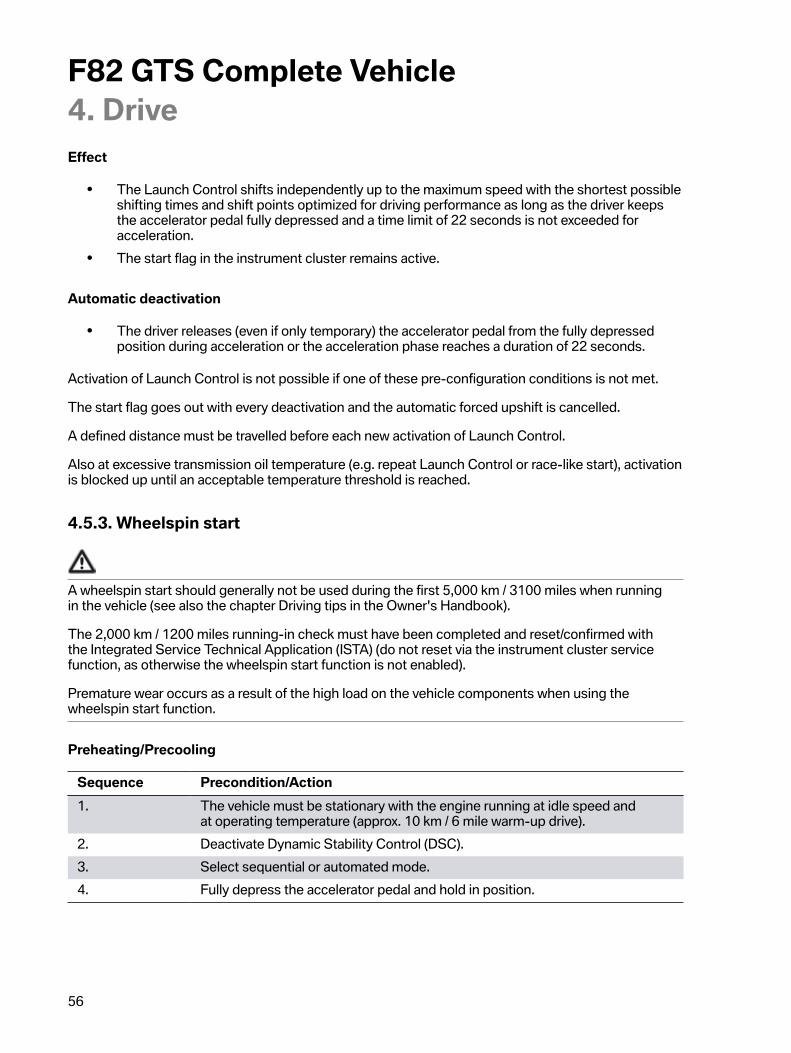
Preheating/Precooling
Sequence Precondition/Action1. The�vehicle�must�be�stationary�with�the�engine�running�at�idle�speed�and
at�operating�temperature�(approx.�10 km�/�6�mile�warm-up�drive).2. Deactivate�Dynamic�Stability�Control�(DSC).3. Select�sequential�or�automated�mode.4. Fully�depress�the�accelerator�pedal�and�hold�in�position.

F82�GTS�Complete�Vehicle4.�Drive
57
Effect
• The�vehicle�accelerates�with�maximum�power�and�with�corresponding�wheel�slip,depending�on�the�surface.
• In�sequential�mode,�the�driver�must�shift�up�manually�so�that�he�does�not�drive�against�thespeed�limiter.
• In�the�case�of�automated�upshifts,�the�M�DCT�carries�out�the�upshifts�independently.
In�addition�to�the�Launch�Control�and�wheelspin�start�functions,�the�M�DCT�also�offers�additionalM�functions�such�as�Stability�Clutch�Control�(opening�the�clutch�to�stabilize�the�vehicle�in�the�eventof�oversteer)�or�"Creep�on�Demand"�(from�vehicle�standstill,�the�driver�activates�the�"creep�mode"familiar�from�automatic�transmissions�by�touching�the�accelerator�pedal).
4.5.4.�Emergency�gearbox�release
The�emergency�gearbox�release�is�not�available�like�on�the�F80/F82�and�F83.�For�towing�of�the�vehicle,please�observe�the�information�in�the�Owner's�Handbook�for�the�vehicle.
4.5.5.�Service�information
Transmission�oil�circuit
Maximum�cleanliness�must�be�ensured�if�work�has�to�be�performed�on�the�oil�circuit�of�the�twin-clutchgearbox,�e.g.�after�an�accident,�or�if�the�oil�circuit�has�to�be�opened�due�to�a�repair.�This�includes:
• Carefully�clean�the�external�oil�circuit�areas�before�disassembling�the�components�or�openingthe�oil�circuit.
• Immediately�close�off�openings�and�lines�after�disassembly�without�delay�using�clean,�originalseal�plugs.�Do�not�use�unsealed�components�or�replacement�parts�of�the�oil�circuit�withoutchecking�for�cleanliness�and�where�possible�competent�repair.
• The�workbay�at�which�a�M�DCT�is�opened�must�be�absolutely�clean�and�protected�against�dirtcontamination,�also�during�work�interruptions.�For�example�by�using�appropriate,�clean�andlint-free�cloths.�Refer�to�page�81
Lifetime�oil�filling
As�for�the�F80/F82�and�the�F83�with�M�DCT�Drivelogic,�no�transmission�oil�change�is�currentlyplanned�at�2,000�km�/�1,200�mile�(running-in�check)�or�at�every�third�engine�oil�change.
Repair/Part�exchange
Depending�on�the�type�of�repair,�the�data�status�of�the�M�DCT�must�be�read�out�beforehand�and�readin�again�after�the�component�has�been�replaced�(e.g.�replacement�of�mechatronics�module).
Depending�on�the�type�of�repair�(e.g.�dual�clutch�change),�the�"Neutral"�gear�selection�position�mustbe�selected�before�the�engine�is�stopped.
F82�GTS�Complete�Vehicle4.�Drive
58
The�current�information�and�specifications�in�the�documents�in�the�Integrated�Service�TechnicalApplication�(ISTA)�must�be�observed�in�each�case.
4.6.�Rear�axle�final�drive
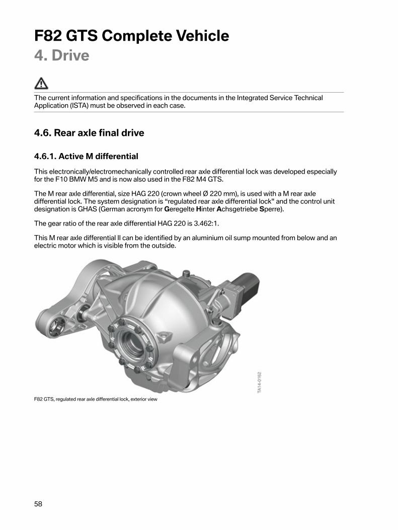
4.6.1.�Active�M�differentialThis�electronically/electromechanically�controlled�rear�axle�differential�lock�was�developed�especiallyfor�the�F10�BMW�M5�and�is�now�also�used�in�the�F82�M4�GTS.
The�M�rear�axle�differential,�size�HAG�220�(crown�wheel�Ø�220 mm),�is�used�with�a�M�rear�axledifferential�lock.�The�system�designation�is�“regulated�rear�axle�differential�lock"�and�the�control�unitdesignation�is�GHAS�(German�acronym�for�Geregelte�Hinter�Achsgetriebe�Sperre).
The�gear�ratio�of�the�rear�axle�differential�HAG�220�is�3.462:1.
This�M�rear�axle�differential�II�can�be�identified�by�an�aluminium�oil�sump�mounted�from�below�and�anelectric�motor�which�is�visible�from�the�outside.
F82�GTS,�regulated�rear�axle�differential�lock,�exterior�view

F82�GTS�Complete�Vehicle4.�Drive
59
Demand-controlled�lock
The�lock�is�a�demand-controlled�rear-axle�differential�lock�which�is�active�in�the�following�situations:
• Acceleration/pullaway.• Differential�speed�at�the�rear�axle�for�straight-ahead�driving�under
load�due�to�various�coefficients�of�friction,�left/right.• Dynamic�cornering.• Power�oversteer�(drifting).• Stabilization�in�coasting/overrun�mode.
Further�information�on�the�active�M�differential�is�provided�in�the�Technical�Training�Manual�ST1402F80/F82�Complete�Vehicle.
4.6.2.�Service�information• After�replacement�of�the�GHAS�control�unit,�it�is�necessary�to�perform�encoding�(activation�of
vehicle-related�characteristic�curve)�and�then�initial�calibration.�The�fault�memory�must�then�bedeleted.
• After�the�replacement�of�the�entire�M�rear�axle�differential�a�calibration�must�be�performed�andthen�the�fault�memory�must�be�deleted.
• For�a�replacement�of�the�electric�motor,�electric�motor�plus�intermediate�gear�or�oiltemperature�sensor,�only�the�fault�memory�must�be�deleted.
The�final�drive�transmission�oil�is�currently�replaced�at�2,000 km�/�1,200�mile�(running-in�check)�and�atevery�5th�engine�oil�change.�After�this,�the�running-in�check�must�be�reset�with�the�BMW�workshopsystem�Integrated�Service�Technical�Application,�ISTA.
The�current�information�and�specifications�in�the�Integrated�Service�Technical�Application�(ISTA)must�be�observed.
F82�GTS�Complete�Vehicle5.�Chassis�and�Suspension
60
5.1.�Front�axle�and�rear�axleIn�order�to�optimally�transfer�the�outstanding�engine�performance�to�the�road�in�every�driving�situationand�also�under�extreme�conditions,�the�F82�M4�GTS�also�features�chassis�and�suspension�technologythat�has�been�developed�on�the�basis�of�extensive�motor�sports�competence�and�experience.�In�termsof�components�and�mounting,�its�chassis�and�suspension�is�based�on�the�front�and�rear�axle�design�ofthe�F82�BMW�M4�Coupé.
In�deviation�from�this,�an�adjustable�chassis�developed�especially�for�the�F82�M4�GTS�is�installed.�Theadjustable�chassis�is�built�by�KW�Automotive�GmbH�according�to�the�specifications�of�M�GmbH�andfeatures�dampers�where�the�rebound�and�compression�stages�can�be�adjusted�separately�from�eachother.�The�adjustable�chassis�is�bolted�together�with�the�body�at�the�front�using�support�rings.
The�damper�geometry�and�damper�components�on�the�front�and�rear�axle�with�springs�were�adaptedfor�use�in�the�F82�M4�GTS�and�are�provided�with�M-specific�tuning.
The�following�components�were�adapted�for�the�F82�M4�GTS:
• Twin-tube�gas-oil�pressure�shock�absorbers�at�the�front�and�rear�with�adapted�tube�geometry.• Valve�block�geometry�for�adjusting�compression�and�rebound.• Specific�support�bearings�at�the�front�in�sealed�uniball�design�with�fixed�camber�and�castor
angles.• Specific�support�bearings�at�rear.• Rear�bottom�shock�absorber�eye�screwed�via�a�sealed�uniball�bearing.• Separate�swivel�bearing�at�front�to�accommodate�the�shock�absorber�tube.• Specific�front�anti-roll�bar�links�adapted�to�shock�absorbers.• Specific�spring�geometry�of�the�coil�springs�at�front�and�rear.• Stiffening�plate�cover�made�of�CFRP.

F82�GTS�Complete�Vehicle5.�Chassis�and�Suspension
61
5.1.1.�Front�axle
F82,�BMW�M4�GTS�front�axle
Index Explanation1 Hexagon�for�rebound�adjustment2 Support�ring3 Support�bearing4 Separate�compression�valve5 Knurled�wheels�for�compression�stage�(Larger�wheel�for�high�speed�and�the
smaller�wheel�for�low�speed)6 Stiffening�plate7 Swivel�bearing8 Anti-roll�bar�link9 Twin-tube�gas-oil�pressure�shock�absorber10 Coil�spring
F82�GTS�Complete�Vehicle5.�Chassis�and�Suspension
62
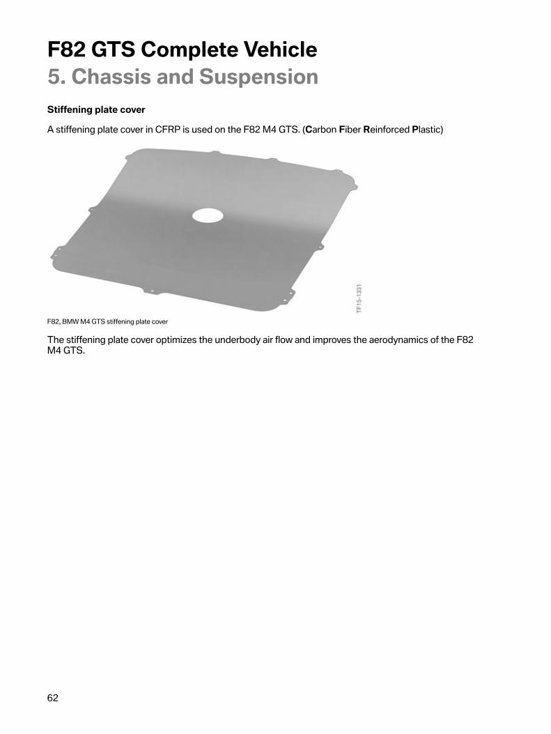
Stiffening�plate�cover
A�stiffening�plate�cover�in�CFRP�is�used�on�the�F82�M4�GTS.�(Carbon�Fiber�Reinforced�Plastic)
F82,�BMW�M4�GTS�stiffening�plate�cover
The�stiffening�plate�cover�optimizes�the�underbody�air�flow�and�improves�the�aerodynamics�of�the�F82M4�GTS.

F82�GTS�Complete�Vehicle5.�Chassis�and�Suspension
63
5.1.2.�Rear�axle
F82�GTS,�rear�axle
Index Explanation1 Support�bearing2 Knurled�wheel�for�rebound3 Separate�compression�valve4 Knurled�wheel�for�compression�stage�(Larger�wheel�for�high�speed�and�the
smaller�wheel�for�low�speed)5 Coil�spring6 Shock�absorber�mount,�bottom7 Twin-tube�gas-oil�pressure�shock�absorber

F82�GTS�Complete�Vehicle5.�Chassis�and�Suspension
64
5.2.�Adjustable�high-performance�chassis�and�suspensionThe�chassis�and�suspension�features�the�following�additional�adjustment�options�for�an�individualmotor�racing�setup:
• Freely�adjustable�damping�technology�with�16�exact�clicks�for�rebound�adjustment.• Freely�adjustable�damping�technology�with�6�clicks�in�the�low-speed�range�for
compression�adjustment.• 14�clicks�in�the�high-speed�range�for�compression�adjustment.• Continuously�adjustable�lowering�of�the�front�and�rear�axles�(threaded�spring�struts
on�front�axle/springs�with�height�adjustment�facility�and�damper�on�rear�axle).
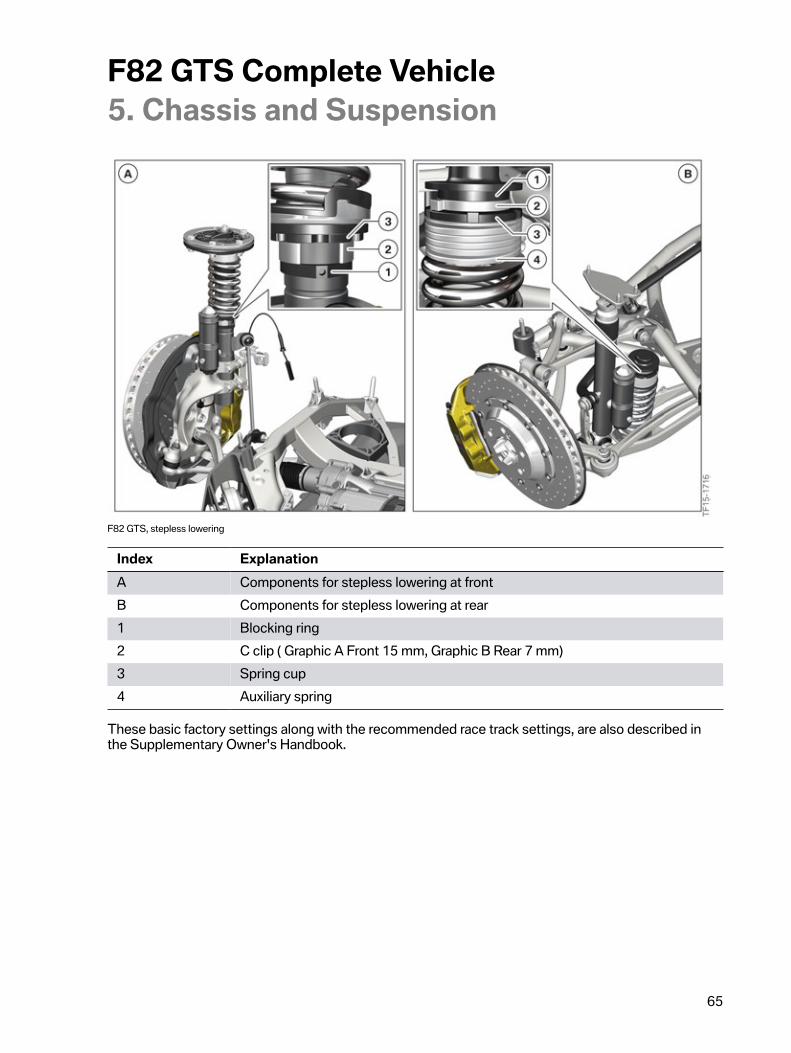
5.2.1.�Stepless�loweringThe�factory�setting�is�optimal�for�both�street�operation�and�driving�on�race�tracks�(Nordschleife-Nürburgring).�The�factory�settings�must�always�be�adjusted�for�operation�on�public�roads.�The�factorysetting�is�marked�by�so-called�C�clips.�The�C�clips�are�installed�between�the�lower�edge�of�the�springcup�and�"race�track�setup"�blocking�ring.�These�clips�can�be�removed�in�order�to�lower�the�chassis.�Ifthe�C�clips�have�been�removed�and�the�chassis�adjusted�away�from�the�factory�setting,�this�no�longercorresponds�to�the�approval�for�operation�on�public�roads.�A�height�adjustment�automatically�results�ina�change�in�camber�and�toe.
The�vehicle�height�can�be�lowered�by�15�mm�at�the�front�and�12�mm�at�the�rear.�It�is�necessary�to�undothe�spring�cup�of�the�dampers�to�perform�adjustment�on�the�rear�axle.�This�is�due�to�the�self-lockingthread�and�a�residual�spring�stress�with�the�installed�damper.�If�the�"race�track�setup"�blocking�ringis�removed,�this�may�result�in�the�vehicle�being�lowered�by�an�inadmissible�amount.�The�blockingring�is�secured�by�means�of�a�break�away�screw.�The�"race�track�setup"�blocking�ring�is�adjusted�byBMW�M�GmbH�and�is�provided�with�a�break�away�screw.�As�a�result,�the�ring�can�be�removed�only�withdifficulty�or�with�force.�In�order�to�perform�correct�adjustment�if�the�blocking�ring�has�been�removed,a�new�"race�track�setup"�blocking�ring�is�required.�Adjustment�must�then�be�performed�on�a�chassisand�suspension�measuring�stand�(alignment�rack)�in�accordance�with�the�procedure�for�spring�-�springstrut�replacement.
F82�GTS�Complete�Vehicle5.�Chassis�and�Suspension
65
F82�GTS,�stepless�lowering
Index ExplanationA Components�for�stepless�lowering�at�frontB Components�for�stepless�lowering�at�rear1 Blocking�ring2 C�clip�(�Graphic�A�Front�15�mm,�Graphic�B�Rear�7�mm)3 Spring�cup4 Auxiliary�spring
These�basic�factory�settings�along�with�the�recommended�race�track�settings,�are�also�described�inthe�Supplementary�Owner's�Handbook.
F82�GTS�Complete�Vehicle5.�Chassis�and�Suspension
66
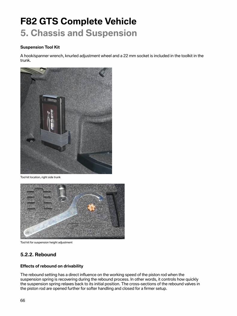
Suspension�Tool�Kit
A�hook/spanner�wrench,�knurled�adjustment�wheel�and�a�22�mm�socket�is�included�in�the�toolkit�in�thetrunk.
Tool�kit�location,�right�side�trunk
Tool�kit�for�suspension�height�adjustment
5.2.2.�Rebound
Effects�of�rebound�on�drivability
The�rebound�setting�has�a�direct�influence�on�the�working�speed�of�the�piston�rod�when�thesuspension�spring�is�recovering�during�the�rebound�process.�In�other�words,�it�controls�how�quicklythe�suspension�spring�relaxes�back�to�its�initial�position.�The�cross-sections�of�the�rebound�valves�inthe�piston�rod�are�opened�further�for�softer�handling�and�closed�for�a�firmer�setup.

F82�GTS�Complete�Vehicle5.�Chassis�and�Suspension
67
• Low�rebound�forces�improve�ride�comfort�at�slow�driving�speeds,�but�reduce�stability�andsteering�precision�when�driving�fast,�particularly�with�a�corresponding�setting.
• High�rebound�forces�further�improve�handling�at�the�front�axle.�This�makes�handling�generallysafer.�However,�high�rebound�forces�may�also�reduce�tire�grip.�Ride�comfort�is�greatlyrestricted�with�high�rebound�forces.
Under�no�circumstances�must�the�vehicle�be�driven�with�one�axle�at�the�maximum�hard�setting�and�theother�axle�at�the�maximum�soft�setting.
Rebound�adjustment
The�knurled�wheel�supplied�with�the�F82�M4�GTS�is�fitted�at�the�top�of�the�front�shock�absorber�toadjust�the�rebound.�Rebound�adjustment�at�the�rear�is�performed�at�the�upper�end�of�the�piston�rodusing�the�integrated�knurled�wheel.�Adjustment�is�performed�from�closed�position�(max.�hardness)towards�the�soft�setting.�Closed�condition�is�reached�when�the�knurled�wheel�is�turned�clockwise�(+)in�hard�direction�until�it�reaches�the�limit�position�(number�"0"�on�the�knurled�wheel).�The�effectiveadjustment�range�is�0�-�16�clicks�in�soft�direction.�The�rebound�damping�is�made�softer�by�turning�thewheel�counter-clockwise�(-�opening).
F82�GTS,�supplied�knurled�wheel�for�front�rebound�adjustment
The�knurled�wheel�operates�a�precision-engineered�valve.�Do�not�under�any�circumstances�attempt�toexceed�the�end�of�the�adjustment�range�with�force.�This�will�damage�the�adjustment�mechanism�andnecessitate�exchange�of�the�complete�shock�absorber.
The�F82�M4�GTS�is�delivered�with�a�basic�rebound�setting.�If�the�shock�absorbers�are�reset�to�thebasic�rebound�setting,�the�values�described�in�the�Supplementary�Owner's�Handbook�apply.
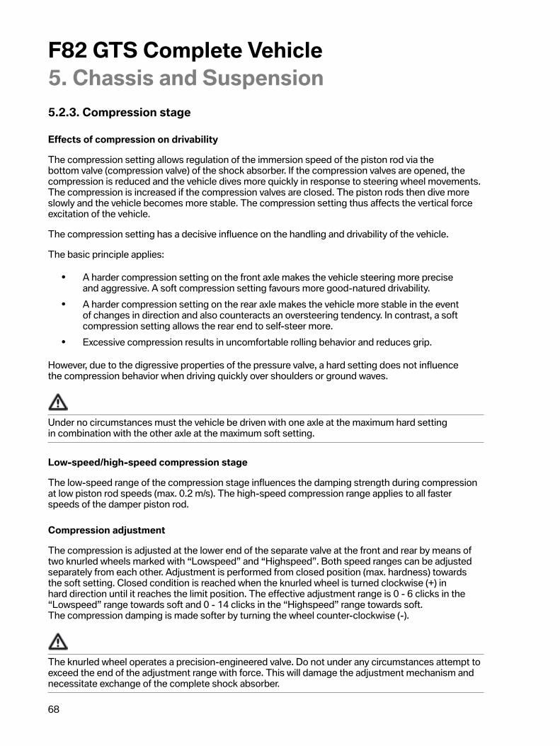
F82�GTS�Complete�Vehicle5.�Chassis�and�Suspension
68
5.2.3.�Compression�stage
Effects�of�compression�on�drivability
The�compression�setting�allows�regulation�of�the�immersion�speed�of�the�piston�rod�via�thebottom�valve�(compression�valve)�of�the�shock�absorber.�If�the�compression�valves�are�opened,�thecompression�is�reduced�and�the�vehicle�dives�more�quickly�in�response�to�steering�wheel�movements.The�compression�is�increased�if�the�compression�valves�are�closed.�The�piston�rods�then�dive�moreslowly�and�the�vehicle�becomes�more�stable.�The�compression�setting�thus�affects�the�vertical�forceexcitation�of�the�vehicle.
The�compression�setting�has�a�decisive�influence�on�the�handling�and�drivability�of�the�vehicle.
The�basic�principle�applies:
• A�harder�compression�setting�on�the�front�axle�makes�the�vehicle�steering�more�preciseand�aggressive.�A�soft�compression�setting�favours�more�good-natured�drivability.
• A�harder�compression�setting�on�the�rear�axle�makes�the�vehicle�more�stable�in�the�eventof�changes�in�direction�and�also�counteracts�an�oversteering�tendency.�In�contrast,�a�softcompression�setting�allows�the�rear�end�to�self-steer�more.
• Excessive�compression�results�in�uncomfortable�rolling�behavior�and�reduces�grip.
However,�due�to�the�digressive�properties�of�the�pressure�valve,�a�hard�setting�does�not�influencethe�compression�behavior�when�driving�quickly�over�shoulders�or�ground�waves.
Under�no�circumstances�must�the�vehicle�be�driven�with�one�axle�at�the�maximum�hard�settingin�combination�with�the�other�axle�at�the�maximum�soft�setting.
Low-speed/high-speed�compression�stage
The�low-speed�range�of�the�compression�stage�influences�the�damping�strength�during�compressionat�low�piston�rod�speeds�(max.�0.2�m/s).�The�high-speed�compression�range�applies�to�all�fasterspeeds�of�the�damper�piston�rod.
Compression�adjustment
The�compression�is�adjusted�at�the�lower�end�of�the�separate�valve�at�the�front�and�rear�by�means�oftwo�knurled�wheels�marked�with�“Lowspeed”�and�“Highspeed”.�Both�speed�ranges�can�be�adjustedseparately�from�each�other.�Adjustment�is�performed�from�closed�position�(max.�hardness)�towardsthe�soft�setting.�Closed�condition�is�reached�when�the�knurled�wheel�is�turned�clockwise�(+)�inhard�direction�until�it�reaches�the�limit�position.�The�effective�adjustment�range�is�0�-�6�clicks�in�the“Lowspeed”�range�towards�soft�and�0�-�14�clicks�in�the�“Highspeed”�range�towards�soft.The�compression�damping�is�made�softer�by�turning�the�wheel�counter-clockwise�(-).
The�knurled�wheel�operates�a�precision-engineered�valve.�Do�not�under�any�circumstances�attempt�toexceed�the�end�of�the�adjustment�range�with�force.�This�will�damage�the�adjustment�mechanism�andnecessitate�exchange�of�the�complete�shock�absorber.

F82�GTS�Complete�Vehicle5.�Chassis�and�Suspension
69
The�F82�M4�GTS�is�delivered�with�a�basic�compression�setting.�If�the�shock�absorbers�are�reset�to�thebasic�compression�setting,�the�values�described�in�the�Supplementary�Owner's�Handbook�apply.
Further�information�on�use�and�maintenance�of�the�chassis�and�suspension�is�also�provided�in�theSupplementary�Owner's�Handbook.
5.3.�Wheel�alignmentThe�following�test�conditions�must�be�observed�before�wheel�alignment:
• Only�wheel�and�tire�combinations�approved�by�BMW�fitted�on�the�vehicle.• Tread�depth�in�accordance�with�specification.�The�tread�depth�may�differ�between
left�and�right�by�a�maximum�of�1�mm�to�2�mm�on�each�axle.• Tire�pressure�in�accordance�with�specification�(see�label�on�vehicle).• All�chassis�and�suspension�components�must�be�technically�fault-free.• Condition�of�suspension�and�shock�absorbers�OK:�visual�inspection�for�breakage,�etc.
A�wheel�alignment�can�be�performed�only�taking�into�account�the�correct�ride�heights�and�wheel�loads.
5.3.1.�Axle�setting�dataFront�axle Rear�axle
Ride�height 624�mm�±�2�mm* 631�mm�±�2�mm*Camber -1°�45’�±�15’ -2°�±�10’
Total�toe-in 10’ 18’Single�wheel�toe 5’�±�1’ 9’�±�1’
*Reset�by�adjusting�the�spring�cups�while�taking�into�account�the�ride�height�tolerance�and�wheelloads.
5.3.2.�Procedure
1.�Adjust�damping�levels�on�front�axle.
Rebound�(support�bearing):�Turn�knurled�wheel�to�closed�position,�then�open�to�basic�setting�asdescribed�in�the�Supplementary�Owner's�Handbook.
Compression�(damper,�bottom):�Turn�knurled�wheel�to�closed�position,�then�open�to�basic�settingas�described�in�the�Supplementary�Owner's�Handbook.
F82�GTS�Complete�Vehicle5.�Chassis�and�Suspension
70
2.�Adjust�damping�levels�on�rear�axle.
Rebound�(support�bearing):�Turn�knurled�wheel�to�closed�position,�then�open�to�basic�setting�asdescribed�in�the�Supplementary�Owner's�Handbook.
Compression�(damper,�bottom):�Turn�knurled�wheel�to�closed�position,�then�open�to�basic�settingas�described�in�the�Supplementary�Owner's�Handbook.
3.�Check�ride�heights
Drive�vehicle�from�platform�and�carry�out�short�test�drive�to�relieve�the�axle�mounting.�After�pre-adjustment�as�described�above,�the�following�ride�height�should�be�obtained�on�the�vehicle:
• Front�suspension:�setpoint�value�624�mm�±�2�mm�tolerance�adjustable�via�the�spring�cups(settling�of�vehicle�taken�into�account).
• Rear�suspension:�setpoint�value�631�mm�±�2�mm�tolerance�adjustable�via�the�spring�cups(settling�of�vehicle�taken�into�account).
The�vehicle�can�be�measured�according�to�the�repair�instructions�only�if�the�ride�height�is�correct�–otherwise�operations�must�be�repeated�as�describe�above�and�the�ride�heights�corrected�by�adjustingthe�spring�cups.
Note:
• Front�axle�height�adjustment�-�pitch�2�mm�per�thread�turn.�Adjustment�of�1�mm�at�the�springstrut�results�in�a�height�change�on�the�body�of�1�mm.
• Rear�axle�height�adjustment�-�pitch�2�mm�per�thread�turn.�Adjustment�of�1�mm�at�themounting�plate�results�in�a�height�change�on�the�body�of�1.6�mm.
4.�Carry�out�wheel�load�optimization
• Place�vehicle�on�wheel�load�weighing�scales.• Load�driver's�seat�with�80 kg�/�176�lbs.• Vehicle�with�full�fuel�tank.
If�the�cross�weight�(front�left-rear�right/front�right-rear�left)�is�within�±�15�kg�/�33�lbs,�wheel�alignmentcan�be�performed�according�to�the�repair�instructions�and�the�current�nominal�values.
If�the�cross�weight�is�outside�the�tolerance,�the�wheel�loads�must�be�adjusted�correctly�by�adjustingthe�spring�cups,�taking�into�account�the�ride�height�tolerances�±�2�mm.�Correction�should�preferablybe�carried�out�on�the�rear�axle.
5.�Carry�out�wheel�alignment�on�the�front�and�rear�axles.
• Front�axle�single�wheel�toe�5’�±�1’• Rear�axle�single�wheel�toe�9’�±�1’• Rear�axle�camber�-2°�±�10’

F82�GTS�Complete�Vehicle5.�Chassis�and�Suspension
71
6.�Adjust�wheel�loads
• Place�vehicle�on�wheel�load�weighing�scales.• Load�driver's�seat�with�80 kg�/�176�lbs.• Vehicle�with�full�fuel�tank.
Adjustment�of�the�cross�weight�(front�left-rear�right/front�right-rear�left)�to�±�15�kg�/�33�lbs�and�within�±2�mm�ride�height�tolerance.
If�the�cross�weight�is�outside�the�tolerance,�the�wheel�loads�must�be�adjusted�correctly�by�adjustingthe�spring�cups,�taking�into�account�the�ride�height�tolerances�±�2�mm.�Correction�should�preferablybe�carried�out�on�the�rear�axle.
7.�Lock�the�blocking�rings�on�the�front�axle
After�correct�wheel�alignment,�the�blocking�rings�or�ring�on�the�front�axle�must�be�turned�to�the�limitposition�at�the�bottom�of�the�C�clip.�When�the�blocking�ring�is�in�the�limit�position,�tighten�the�tear-offscrew�to�finally�secure�the�set�screw�until�the�tear-off�screw�tears�off.�This�secures�the�blocking�ring�toprevent�manipulation�and�prevents�further�lowering�of�the�vehicle�by�the�customer.
Undo�spring�cup�by�approx.�a�¼�turn�so�that�it�is�easier�to�remove�the�spacer�rings�again�later.
8.�Lock�the�blocking�rings�on�the�rear�axle
Lower�corresponding�rear�axle�side�by�removing�the�bottom�fixing�screw�of�the�shock�absorber�eye.Take�out�the�thread�unit�with�the�spring�cup,�blocking�ring�and�vehicle�mount.�Fit�C�clip�and�turn�theblocking�ring�to�the�limit�position.�When�the�blocking�ring�is�in�the�limit�position,�tighten�the�tear-offscrew�to�finally�secure�the�set�screw�until�the�tear-off�screw�tears�off.�This�secures�the�blocking�ring�toprevent�manipulation�and�prevents�further�lowering�of�the�vehicle�by�the�customer.
Undo�the�spring�cup�by�approx.�a�¼�turn�so�that�it�is�easier�to�remove�the�spacer�rings�again�later.
Fit�the�thread�unit�with�spring�cup,�blocking�ring,�C�clip�and�vehicle�mount�in�the�vehicle�again.�Screwtogether�the�rear�axle�side�with�the�bottom�shock�absorber�eye�again.
If�chassis�and�suspension�components�were�replaced�which�make�it�necessary�to�replace�or�openthe�blocking�ring,�the�new�blocking�ring�must�be�secured�again�by�a�tear-off�screw�after�correct�wheelalignment.
For�any�service�work�required,�the�current�information�and�specifications�in�the�documents�in�theIntegrated�Service�Technical�Application�(ISTA)�must�be�observed�in�each�case.

F82�GTS�Complete�Vehicle5.�Chassis�and�Suspension
72
5.4.�BrakesThe�M�carbon�ceramic�brake,�familiar�from�the�F82�BMW�M4�Coupé�as�optional�equipment,�is�fitted�asthe�standard�brake�system�on�the�F82�M4�GTS.�Motor�sports-oriented�braided�steel�brake�hoses�arealso�used.
The�M�Carbon�ceramic�brake�system�is�also�called�the�C/SiC�brake�system.
Depending�on�the�situation,�this�offers�a�further�increase�in�active�safety�vis-a-vis�the�M�Compoundbrake.�In�a�direct�comparison�it�also�offers:
• Even�more�direct/spontaneous�use�of�brake�force.• Maximum�heat�resistance�even�with�continuous�sporty�operation.• Higher�fading�stability.• Greatly�reduced�wear�on�the�brake�discs.• 7 kg�/�15�lbs�weight�reduction�of�rotating�wheel�masses.• Increased�suitability�for�winter�driving�conditions�thanks�to�corrosion�resistance.
F82�GTS,�M�carbon�ceramic�brake�on�front�axle
The�brake�discs�are�manufactured�by�Brembo�SGL�Carbon�Ceramic�Brakes�GmbH.
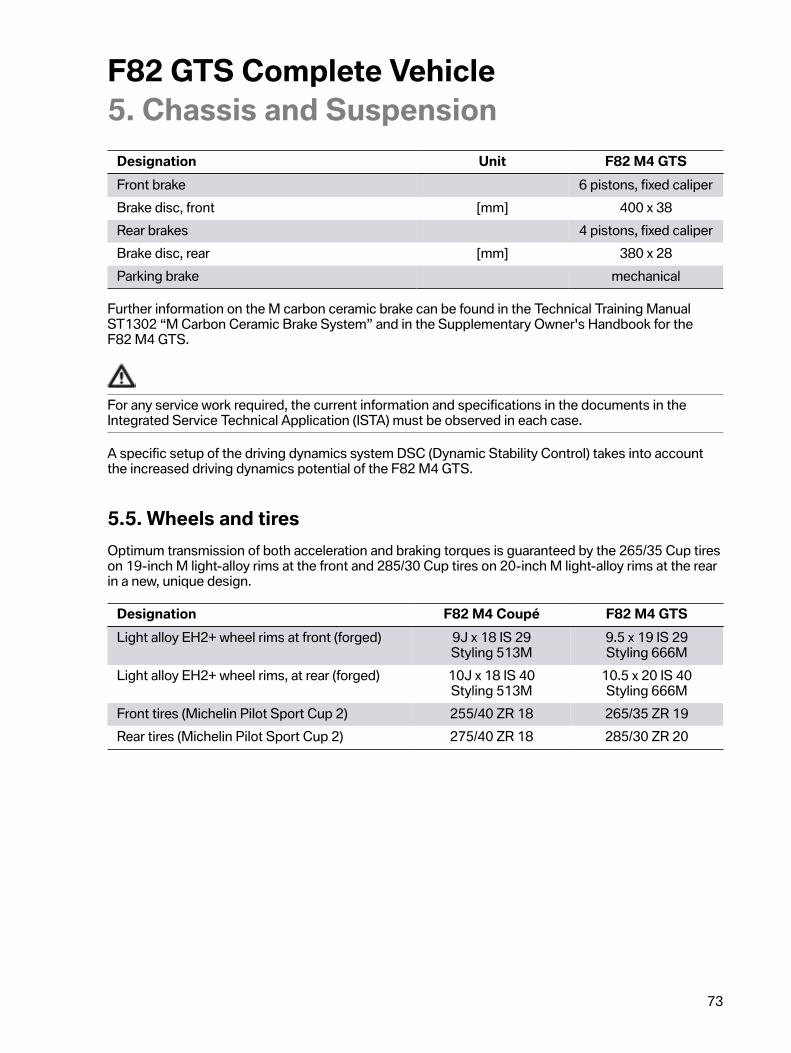
F82�GTS�Complete�Vehicle5.�Chassis�and�Suspension
73
Designation Unit F82�M4�GTSFront�brake 6�pistons,�fixed�caliperBrake�disc,�front [mm] 400�x�38Rear�brakes 4�pistons,�fixed�caliperBrake�disc,�rear [mm] 380�x�28Parking�brake mechanical
Further�information�on�the�M�carbon�ceramic�brake�can�be�found�in�the�Technical�Training�ManualST1302�“M�Carbon�Ceramic�Brake�System”�and�in�the�Supplementary�Owner's�Handbook�for�theF82�M4�GTS.
For�any�service�work�required,�the�current�information�and�specifications�in�the�documents�in�theIntegrated�Service�Technical�Application�(ISTA)�must�be�observed�in�each�case.
A�specific�setup�of�the�driving�dynamics�system�DSC�(Dynamic�Stability�Control)�takes�into�accountthe�increased�driving�dynamics�potential�of�the�F82�M4�GTS.
5.5.�Wheels�and�tiresOptimum�transmission�of�both�acceleration�and�braking�torques�is�guaranteed�by�the�265/35�Cup�tireson�19-inch�M�light-alloy�rims�at�the�front�and�285/30�Cup�tires�on�20-inch�M�light-alloy�rims�at�the�rearin�a�new,�unique�design.
Designation F82�M4�Coupé F82�M4�GTSLight�alloy�EH2+�wheel�rims�at�front�(forged) 9J�x�18�IS�29
Styling�513M9.5�x�19�IS�29Styling�666M
Light�alloy�EH2+�wheel�rims,�at�rear�(forged) 10J�x�18�IS�40Styling�513M
10.5�x�20�IS�40Styling�666M
Front�tires�(Michelin�Pilot�Sport�Cup�2) 255/40�ZR�18 265/35�ZR�19Rear�tires�(Michelin�Pilot�Sport�Cup�2) 275/40�ZR�18 285/30�ZR�20

F82�GTS�Complete�Vehicle5.�Chassis�and�Suspension
74
5.5.1.�WheelsAs�standard,�forged�19”�M�light-alloy�wheels�are�used�at�the�front�and�20”�M�light-alloy�wheels�at�therear�in�666M�styling.
F82�GTS,�light-alloy�wheels�in�styling�666M
5.5.2.�Cup�tiresMichelin�Pilot�Sport�Cup�2�tires�designed�for�the�race�track�which�also�meet�the�legal�regulations�foruse�on�public�roads.�These�tires�were�optimized�specifically�for�use�on�the�race�track�in�dry�conditions.On�wet�roads�or�race�tracks�with�a�risk�of�hydroplaning,�it�is�necessary�to�drive�at�an�appropriate�speedand�with�activated�driving�dynamics�systems.
The�Michelin�Pilot�Sport�Cup�2�tires�are�similar�to�a�pure�sport�tire�in�terms�of�design,�structure�andrubber�compound,�but�have�a�dominant�influence�on�the�excellent�drivability�of�the�F82�M4�GTSthanks�to�their�very�heat-resistant�rubber�compound.
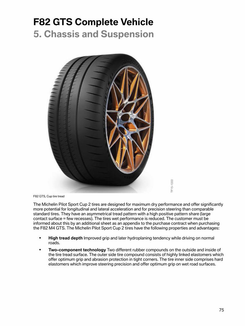
F82�GTS�Complete�Vehicle5.�Chassis�and�Suspension
75
F82�GTS,�Cup�tire�tread
The�Michelin�Pilot�Sport�Cup�2�tires�are�designed�for�maximum�dry�performance�and�offer�significantlymore�potential�for�longitudinal�and�lateral�acceleration�and�for�precision�steering�than�comparablestandard�tires.�They�have�an�asymmetrical�tread�pattern�with�a�high�positive�pattern�share�(largecontact�surface�=�few�recesses).�The�tires�wet�performance�is�reduced.�The�customer�must�beinformed�about�this�by�an�additional�sheet�as�an�appendix�to�the�purchase�contract�when�purchasingthe�F82�M4�GTS.�The�Michelin�Pilot�Sport�Cup�2�tires�have�the�following�properties�and�advantages:
• High�tread�depth�Improved�grip�and�later�hydroplaning�tendency�while�driving�on�normalroads.
• Two-component�technology�Two�different�rubber�compounds�on�the�outside�and�inside�ofthe�tire�tread�surface.�The�outer�side�tire�compound�consists�of�highly�linked�elastomers�whichoffer�optimum�grip�and�abrasion�protection�in�tight�corners.�The�tire�inner�side�comprises�hardelastomers�which�improve�steering�precision�and�offer�optimum�grip�on�wet�road�surfaces.
F82�GTS�Complete�Vehicle5.�Chassis�and�Suspension
76
The�following�must�be�observed�before�intensive�race�track�use:
• Always�check�the�condition�of�the�tires�for�wear�and�possible�damage.• Warm�up�the�tires�by�driving�moderately�for�a�few�laps.
• The�optimum�tire�pressure�of�the�Michelin�Pilot�Sport�Cup�2�is�between�2.0�bar�(29�psi)�and2.9�bar�(42�psi)�at�the�front�and�rear.
• Never�drive�with�a�tire�pressure�of�less�than�2.0�bar�(29�psi).
Observe�the�following�after�race�track�use�and�before�driving�on�public�roads:
• Adjust�the�tire�pressure�recommended�by�the�vehicle�manufacture�on�the�cold�tire.• Allow�the�tire�to�cool�down�before�making�corresponding�tire�pressure�adjustments.• Always�check�the�condition�of�your�tires�to�make�sure�that�they�comply�with�the�legal
regulations�for�use�on�public�roads.• If�the�driving�dynamics�systems�were�deactivated,�activate�these�again.
TIRE�PRESSURE�RECOMMENDATIONS
The�correct�tire�pressures�for�approved�tire�sizes�can�be�found�on�the�door�post�of�the�driver's�door.Further�information�on�tire�pressures�is�provided�in�the�Supplementary�Owner's�Handbook.�Thepressure�specifications�apply�for�tires�at�ambient�temperature.
ATTENTION
• If�the�Michelin�Pilot�Sport�Cup�2�tires�are�not�used�for�an�extended�period,�it�is�recommendedto�remove�the�wheels�from�the�vehicle�and�to�reduce�the�tire�pressure�to�half�the�usual�value.
• The�tires�should�be�stored�in�a�clean,�dry�and�dark�location�in�accordance�with�therecommendations�from�Michelin�and�at�temperatures�above�0�°C�/�32�°F.
• The�use,�storage�or�handling�of�Michelin�Pilot�Sport�Cup�2�tires�at�ambient�temperaturesbelow�minus�–10�°C�/�14�°F�should�be�avoided.�Elements�of�the�rubber�compound�may�bedamaged�under�these�conditions.�This�will�impair�the�performance�characteristics�of�thetire�and�may�even�cause�cracks�or�breaks�in�the�tire�tread�which�make�further�use�of�the�tireimpossible.
• Never�use�a�tire�that�has�cracks,�breaks�or�other�damage�on�the�tire�tread�or�sidewalls.�In�caseof�doubt,�the�customer�should�consult�BMW�Service.
F82�GTS�Complete�Vehicle5.�Chassis�and�Suspension
77
• In�the�case�of�intensive�race�track�use,�the�tires�or�tire�casing�may�become�damaged�afterextended�driving�and�frequent�driving�over�the�curb.
• The�tires�must�be�checked�carefully�if�they�have�been�frequently�driven�over�curb�or�thevehicle�has�left�the�track.�In�such�a�case,�it�is�necessary�to�remove�the�tire�from�the�wheel�inorder�to�inspect�both�the�outer�and�inner�sides�of�the�tire.
• A�visual�check�of�the�tires�must�be�performed�after�every�“run”�and�before�returning�to�thetrack.

F82�GTS�Complete�Vehicle6.�Vehicle�Electrical�System
78
6.1.�Active�Sound�Design�ASDThe�Active�Sound�Design�ASD�is�not�installed�in�the�F82�M4�GTS.
6.2.�Heating�and�air�conditioning�systemThe�integrated�1/1�single�zone�heating/air�conditioning�system�is�used�in�the�F82�M4�GTS.The�integrated�2/1�zone�automatic�heating/air�conditioning�system�is�not�available�for�the�F82�M4�GTSfor�weight�reasons.
In�the�zone�specification�the�first�number�denotes�the�number�of�controllable�temperature�zones(temperature�selector�wheels)�and�the�second�number�the�number�of�controllable�airflow�volume�andair�distribution�zones�(separate�fan�settings).
6.3.�Radio�and�speaker�systemThe�radio�and�speaker�system�was�also�reduced�to�a�minimum�for�weight�and�concept�reasons.As�a�result,�2�central�bass�speakers�are�used�under�the�front�seats.�These�are�supplemented�by�2�mid-range�speakers�on�the�left�and�right�of�the�storage�shelf�supported�by�2�tweeters�which�complete�theaudio�system�in�the�F82�M4�GTS.
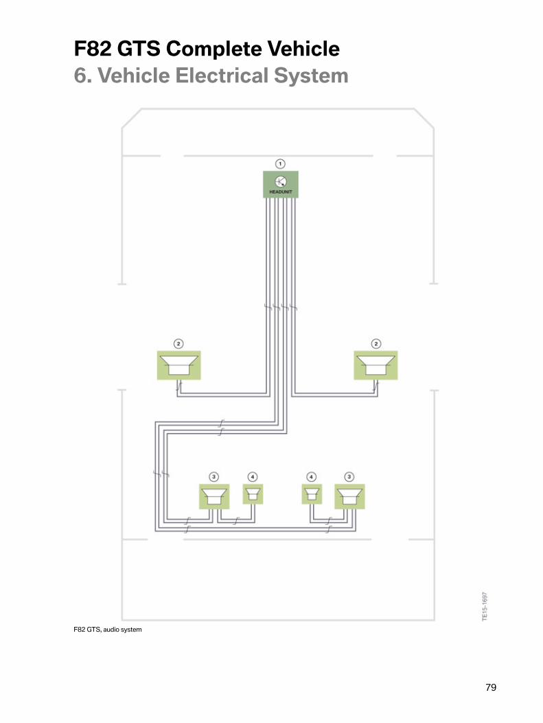
F82�GTS�Complete�Vehicle6.�Vehicle�Electrical�System
79
F82�GTS,�audio�system

F82�GTS�Complete�Vehicle6.�Vehicle�Electrical�System
80
Index Explanation1 Head�unit2 Central�bass�(under�front�seats)3 Mid-range�speakers�(in�parcel�shelf)4 Tweeters�(in�parcel�shelf)
F82�GTS�Complete�Vehicle7.�Information�for�Service
81
7.1.�F82�M4�GTS• At�the�vehicle�handover,�the�customer�must�sign�a�handover�record�which�informs�him�about
the�special�features�of�the�F82�BMW�M�4�GTS.�The�customer�must�confirm�the�content�of�thishandover�record�with�his�signature.�In�the�handover�record,�the�customer�is�informed,�amongother�things,�about�reduced�comfort�in�the�areas�of�drive�system�and�chassis�and�suspensionas�well�as�about�the�deviating�conditions�for�use�of�the�F82�M4�GTS.
7.2.�Replacement�part�orders• The�complete�replacement�parts�supply�for�the�F82�M4�GTS�is�done�through�the�central�BMW
Group�Parts�organization.�As�usual,�the�vehicle�must�be�identified�via�the�Electronic�PartsCatalogue�with�the�vehicle�identification�number.�The�GTS-specific�parts�are�also�output�viathe�EPC�with�the�part�number�for�the�F82�M4�GTS.
• Replacement�part�supply�for�specific�parts�of�all�predecessors�of�the�F82�M4�GTS�is�handledthrough�BMW�M�GmbH.�Supplementary�part�numbers�for�the�M3�GTS�and�CRT�can�beobtained�from�the�ASAP�“Aftersales�Assistance�Portal”.�All�BMW�M4�common�parts�can�beidentified�directly�in�the�Electronic�Parts�Catalogue�and�ordered�from�the�central�BMW�GroupParts�organization.
7.3.�Body• The�prescribed�settings�of�the�front�spoiler�for�street�use�as�well�as�the�recommendations�for
motor�sports�settings�and�tightening�torques�are�described�in�the�Supplementary�Owner'sHandbook.
• The�prescribed�settings�of�the�rear�spoiler�for�street�use�as�well�as�the�recommendations�formotor�sports�settings�and�tightening�torques�are�described�in�the�Supplementary�Owner'sHandbook�of�the�F82�M4�GTS.
• In�general,�the�further�the�front�spoiler�is�extended,�the�larger�the�inclination�angle�of�the�rearspoiler�should�be.�Otherwise,�a�safe�vehicle�balance�is�not�guaranteed�at�high�speeds.
• Adjustments�to�the�rear�spoiler�must�be�performed�only�when�the�trunk�is�closed.�Whenundoing�the�screws,�it�must�be�ensured�that�the�rear�spoiler�does�not�tip�down.
7.4.�Seat�belts• The�six-point�seat�belts�for�driver�and�front�passenger�must�be�fitted�only�for�race�track
operation.�Separate�instructions�for�use/installation�instructions�for�the�six-point�seat�belts�arerequired.
• Three-point�seat�belts�are�installed�from�the�factory�and�must�be�used�for�street�operation.
F82�GTS�Complete�Vehicle7.�Information�for�Service
82
7.5.�S55B30T0�engine• Like�on�the�F80/F82�and�F83,�the�engine�oil�is�currently�renewed�at�2,000�km�/�1200�mile
(running-in�check).�After�this,�the�running-in�check�must�be�reset�with�the�BMW�workshopsystem�Integrated�Service�Technical�Application�ISTA.
• Changed�engine�oil�fill�quantity�for�the�S55�engine�in�the�F82�M4�GTS.�The�fill�quantity�for�anengine�oil�change�with�filter�is�7�liters.�Engine�oil�fill�quantity�without�filter�exchange�6.5�liters.
7.6.�Water�injection• When�the�engine�is�switched�off�and�the�water�injection�system�is�drained,�operating�noises
occur�which�may�be�perceived�by�the�customer.�These�operating�noises�cannot�be�avoideddue�to�the�operating�principle�of�the�system.
• When�filling�the�water�injection�system,�only�commercially�available�distilled�water(demineralized�-�decalcified)�must�be�used�for�the�F82�M4�GTS.�Other�fluid,�mixtures�ormixtures�with�alcohols�are�not�approved�by�BMW.
• The�10�µm�fine�filter�in�the�valve�block�can�be�removed�and�installed�by�means�of�the�hexagonscrew.�The�fine�filter�should�be�replaced�at�every�2nd�oil�service/20,000�miles.
• The�water�injection�system�can�be�diagnosed�via�the�DME.�The�current�information�andspecifications�in�the�documents�in�the�Integrated�Service�Technical�Application�(ISTA)�must�beobserved�in�each�case.
• The�water�consumption�depends�greatly�on�the�vehicle�operating�conditions�and�variescorrespondingly.�As�a�rule�of�thumb,�a�consumption�of�0.6�/�–�1�liter�per�100�km�or�0.15gallons�–�0.26�gallons�per�62�miles�can�be�expected�on�the�race�track.�In�the�case�of�dynamicmotorway�driving�(engine�speed�>�5000�rpm�and�high�load)�in�everyday�use,�it�will�probably�benecessary�to�top�up�with�water�at�only�every�5th�refuelling�operation.
• If�water�injection�is�no�longer�available,�the�engine�power�will�then�correspond�to�the�standardpower�of�the�S55�engine.Further�information�on�use�and�maintenance�of�the�water�injection�system�is�provided�in�theSupplementary�Owner's�Handbook.
7.7.�M�DCTMaximum�cleanliness�must�be�ensured�if�work�has�to�be�performed�on�the�oil�circuit�of�the�twin-clutchgearbox,�e.g.�after�an�accident,�or�if�the�oil�circuit�has�to�be�opened�due�to�a�repair.�This�includes:
• Carefully�clean�the�external�oil�circuit�areas�before�disassembling�the�components�or�openingthe�oil�circuit.
• Immediately�close�off�openings�and�lines�after�disassembly�without�delay�using�clean,�originalseal�plugs.�Do�not�use�unsealed�components�or�replacement�parts�of�the�oil�circuit�withoutchecking�for�cleanliness�and�where�possible�competent�repair.
• The�workbay�at�which�an�M�DCT�is�opened�must�be�absolutely�clean�and�protected�againstdirt�contamination.�If�interrupted�during�repairs,�clean�and�lint�free�cloths�must�be�used�toprotect�exposed�components.
F82�GTS�Complete�Vehicle7.�Information�for�Service
83
As�for�the�F80/F82�and�the�F83�with�M�DCT�Drivelogic,�no�transmission�oil�change�is�currentlyplanned.
Depending�on�the�type�of�repair,�the�data�status�of�the�M�DCT�must�be�read�out�beforehand�and�readin�again�after�the�component�has�been�replaced�(e.g.�replacement�of�mechatronics�module).
Depending�on�the�type�of�repair�(e.g.�dual�clutch�change),�the�"Neutral"�gear�selection�position�mustbe�selected�before�the�engine�is�stopped.
The�emergency�gearbox�release�is�not�installed�like�on�the�F80/F82�and�F83.�For�towing�away,�pleaseobserve�the�information�in�the�Owner's�Handbook�of�the�vehicle.
7.8.�Launch�Control�and�wheelspin�start• The�Launch�Control�and�wheelspin�start�functions�should�generally�not�be�used�during�the
first�5,000 km�/�3,100�miles�when�running�in�the�vehicle�(see�also�the�chapter�Driving�tips�inthe�Owner's�Handbook).
• The�2,000 km�/�1,200�mile�running-in�check�must�have�been�completed�and�reset/confirmedwith�the�Integrated�Service�Technical�Application�(ISTA)�(do�not�reset�via�the�instrumentcluster�service�function,�as�otherwise�the�Launch�Control�and�wheelspin�start�functions�arenot�enabled).
• Premature�wear�occurs�as�a�result�of�the�high�load�on�the�vehicle�components�when�using�theLaunch�Control�and�wheelspin�start�functions.
7.9.�Active�M�differential• For�a�replacement�of�the�GHAS�control�unit�an�encoding�(activation�of�vehicle-related
characteristic�curve)�and�then�an�initial�calibration�are�necessary�and�then�the�fault�memorymust�be�deleted.
• After�the�replacement�of�the�entire�M�rear�axle�differential�a�calibration�must�be�performed�andthen�the�fault�memory�must�be�deleted.
• For�a�replacement�of�the�electric�motor,�electric�motor�plus�intermediate�gear�or�oiltemperature�sensor,�only�the�fault�memory�must�be�deleted.
• The�final�drive�differential�oil�is�currently�replaced�at�2,000 km�/�1,200�miles�(running-in�check)and�at�every�fifth�engine�oil�change.�After�this,�the�running-in�check�must�be�reset�with�theBMW�workshop�system�Integrated�Service�Technical�Application�ISTA.
7.10.�Adjustable�high-performance�chassis�and�suspension• Under�no�circumstances�must�the�vehicle�be�driven�with�one�axle�at�the�maximum�hard
damper�setting�in�combination�with�the�other�axle�at�the�maximum�soft�setting.• The�knurled�wheel�for�damper�adjustment�operates�a�precision-engineered�valve.�Do�not
under�any�circumstances�attempt�to�exceed�the�end�of�the�adjustment�range�with�force.

F82�GTS�Complete�Vehicle7.�Information�for�Service
84
This�will�damage�the�adjustment�mechanism�and�necessitate�the�exchange�of�the�completeshock�absorber.
• The�F82�M4�GTS�is�delivered�with�a�basic�compression�and�rebound�setting.�If�the�shockabsorbers�are�reset�to�the�basic�compression�and�rebound�setting,�the�values�described�in�theSupplementary�Owner's�Handbook�apply.
• A�hook�wrench�for�lowering�and�a�knurled�wheel�with�hexagon�for�adjusting�the�damperare�included�in�the�toolkit�for�this�purpose.
• Further�information�on�use�and�maintenance�of�the�adjustable�high-performance�chassis�andsuspension�is�provided�in�the�Supplementary�Owner's�Handbook.
7.11.�Wheel�alignment• A�wheel�alignment�can�be�performed�only�by�taking�into�account�the�correct�ride�heights�and
wheel�loads.• If�chassis�and�suspension�components�were�replaced�which�make�it�necessary�to�replace�or
open�the�blocking�ring,�the�new�blocking�ring�must�be�secured�again�by�a�break�off�screw�aftercorrect�wheel�alignment.
7.12.�Tires• If�the�Michelin�Pilot�Sport�Cup�2�tires�are�not�used�for�an�extended�period,�it�is�recommended
to�remove�the�wheels�from�the�vehicle�and�to�reduce�the�tire�pressure�to�half�the�usual�value.• The�tires�should�be�stored�in�a�clean,�dry�and�dark�location�in�accordance�with�the
recommendations�from�Michelin�and�at�temperatures�above�0�°C�/�32�°F.• Use,�storage�or�handling�of�Michelin�Pilot�Sport�Cup�2�tires�at�ambient�temperatures�below
minus�–10�°C�/�+14�°F�should�be�avoided.�Elements�of�the�rubber�compound�may�be�damagedunder�these�conditions.�This�will�impair�the�performance�characteristics�of�the�tire�and�mayeven�cause�cracks�or�breaks�in�the�tire�tread�which�make�further�use�of�the�tire�impossible.
• Never�use�a�tire�that�has�cracks,�breaks�or�other�damage�on�the�tire�tread�or�sidewalls.�In�caseof�doubt,�the�customer�should�consult�BMW�Service.
• In�the�case�of�intensive�race�track�use,�the�tires�or�tire�casing�may�become�damaged�afterextended�driving�and�frequent�driving�over�the�curb.
• The�tires�must�be�checked�carefully�if�they�have�been�frequently�driven�over�curb�or�thevehicle�has�left�the�track.�In�such�a�case,�it�is�necessary�to�remove�the�tire�from�the�wheel�inorder�to�inspect�both�the�outer�and�inner�sides�of�the�tire.
• A�visual�check�of�the�tires�must�be�performed�after�every�“run”�and�before�returning�to�thetrack.
• The�correct�tire�pressures�for�approved�tire�sizes�can�be�found�on�the�door�post�of�thedriver's�door.�Further�information�on�tire�pressures�is�provided�in�the�Supplementary�Owner'sHandbook.
• Further�information�on�use�and�maintenance�of�the�tires�is�provided�in�the�SupplementaryOwner's�Handbook.


Bayerische�Motorenwerke�AktiengesellschaftQualifizierung�und�TrainingRöntgenstraße�785716�Unterschleißheim,�Germany


