

SCMU5-21/22-0120 1
TENDER
SCHEDULED MAINTENANCE CONTRACT – BOILERS CENTRAL REGION
SCMU5-21/22-0120
NAME OF COMPANY: ______________________________________________________________
CSD Nr: _____________________________________________________________
CRS Nr (CIDB): _________________________________________________________________________
CLOSING DATE: 31 AUGUST 2021 TIME: 11:00 am
Department of Public Works and Infrastructure Qhasana Building Independence Avenue Bhisho Eastern Cape 5605

SCMU5-21/22-0120 2
T1.1 Tender Notice and Invitation to Tender
The Eastern Cape Department of Public Works invites contractors with a CIDB Grading of 5ME PE or 6ME or HIGHER in the following Class of works (ME) to tender for SCHEDULED MAINTENANCE CONTRACT -BOILERS CENTRAL REGION for 24 months. Only tenderers who have suitable experience and suitably qualified personnel in providing similar services to those that are required are eligible to submit tenders. Bid documents will be made available to prospective bidders from 08h00 on 30th July 2021. Due to the requirement to adhere to the COVID 19 safety regulations hard copy documents will not be available at departmental offices. Bidders are to download the documents free of charge from the Department’s website www.ecdpw.gov.za/tenders Bid documents should be printed in single-sided format and bound using a punched/spiral binder No pre-tender briefing session will be held, and any queries regarding the tender can be directed to the relevant officials as per the contact details provided. The responses to any questions of clarity regarding the tender will be distributed to all bidders Queries relating to the issue of these documents may be addressed in writing to Mr. Zamuxolo Billie- email: [email protected] Technical enquiries: may be addressed in writing to Mr. D. Mzomba – email: [email protected] The closing time for receipt of tenders by the ECDPW is 11:00am on 31 August 2021. Telegraphic, telephonic, telex, facsimile, e-mail and late tenders will not be accepted. Bids must be submitted in sealed envelopes clearly marked “SCMU5-21/22-0120: “SCHEDULED MAINTENANCE CONTRACT- BOILERS CENTRAL REGION” must be deposited in the bid box, DEPARTMENT OF PUBLIC WORKS, FRONT CORNER OF QHASANA BUILDING ON THE WAY TO CIDB OFFICES LABELLED “TENDERS”, BISHO.
It is the responsibility of the tenderer/s to ensure that bid documents /proposals are submitted on or before closing time and the correct location as the department will not take responsibility of wrong delivery. Tenderers using courier services for delivery of their bid documents must ensure the delivery is at the correct place / location and time as the department will not be held responsible for wrong delivery. Not delivered to Departmental officials. The Department will not accept responsibility if bids received by officials are not timely deposited in the Bid Box.
Tenders may only be submitted on the tender documentation that is issued. Tenderers must be registered on the National Treasury Central Supplier Data Base and proof of registration must be submitted with the proposal (https://secure.csd.gov.za). Requirements for sealing, addressing, delivery, opening and assessment of tenders are stated in the Tender Data.
This bid fill be evaluated in three (3) phases as follows: Phase One: Administrative Compliance, thereafter Phase Two: Bidders passing stage one above will be thereafter be evaluated on functionality Phase Three: Bidders passing all stages above will thereafter be evaluated on PPPFA
SCMU5-21/22-0120 3
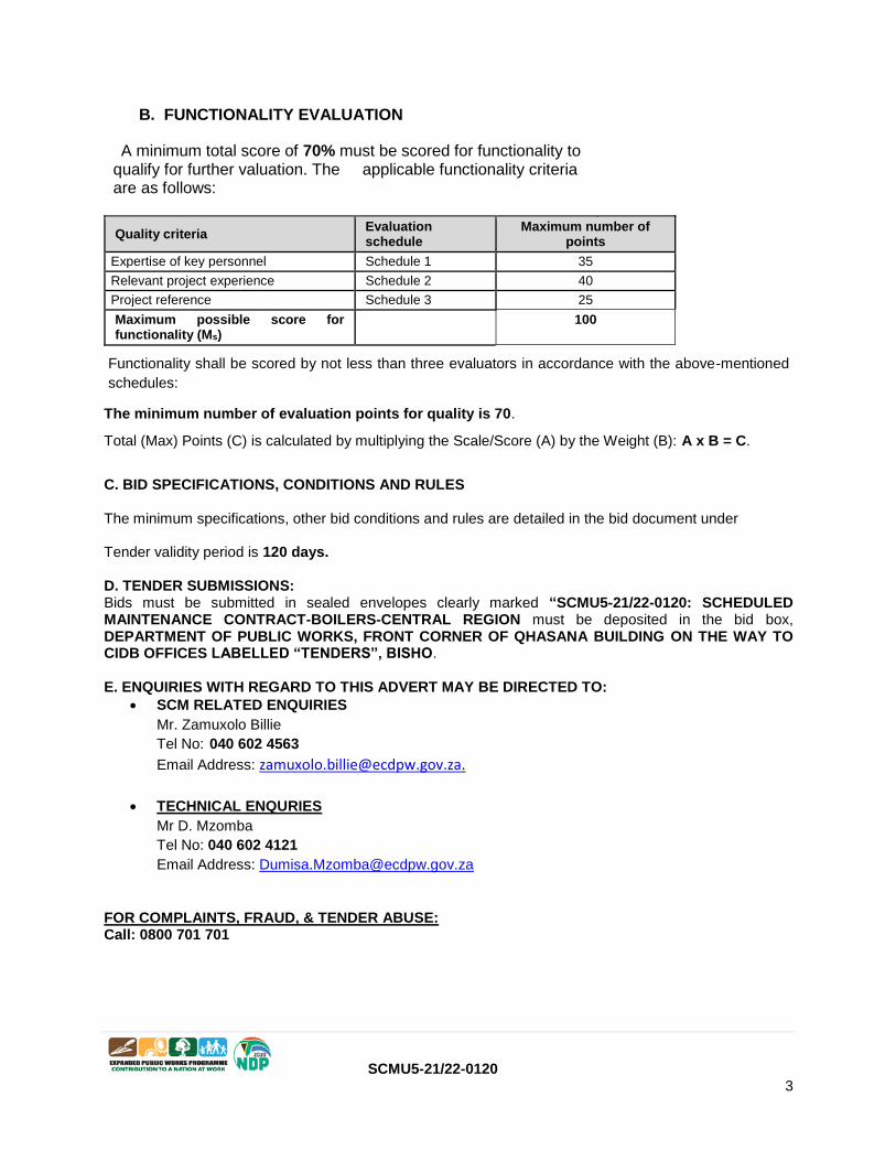
B. FUNCTIONALITY EVALUATION
A minimum total score of 70% must be scored for functionality to qualify for further valuation. The applicable functionality criteria are as follows:
Quality criteria Evaluation schedule
Maximum number of points
Expertise of key personnel Schedule 1 35
Relevant project experience Schedule 2 40
Project reference Schedule 3 25
Maximum possible score for functionality (Ms)
100
Functionality shall be scored by not less than three evaluators in accordance with the above-mentioned
schedules:
The minimum number of evaluation points for quality is 70.
Total (Max) Points (C) is calculated by multiplying the Scale/Score (A) by the Weight (B): A x B = C.
C. BID SPECIFICATIONS, CONDITIONS AND RULES The minimum specifications, other bid conditions and rules are detailed in the bid document under Tender validity period is 120 days. D. TENDER SUBMISSIONS: Bids must be submitted in sealed envelopes clearly marked “SCMU5-21/22-0120: SCHEDULED MAINTENANCE CONTRACT-BOILERS-CENTRAL REGION must be deposited in the bid box, DEPARTMENT OF PUBLIC WORKS, FRONT CORNER OF QHASANA BUILDING ON THE WAY TO CIDB OFFICES LABELLED “TENDERS”, BISHO. E. ENQUIRIES WITH REGARD TO THIS ADVERT MAY BE DIRECTED TO:
SCM RELATED ENQUIRIES
Mr. Zamuxolo Billie
Tel No: 040 602 4563
Email Address: [email protected].
TECHNICAL ENQURIES
Mr D. Mzomba
Tel No: 040 602 4121
Email Address: [email protected]
FOR COMPLAINTS, FRAUD, & TENDER ABUSE: Call: 0800 701 701

SCMU5-21/22-0120 4
T1.2 Tender Data
The conditions of tender are the latest edition of SANS 10845-3, Standard conditions of tender. SANS 10845-3 makes several references to the Tender Data for details that apply specifically to this tender. The Tender Data shall have precedence in the interpretation of any ambiguity or inconsistency between it and the provisions of SANS 10845-3 and as contained in Annexure C of Standard for Uniformity in Construction Procurement (Board Notice 423 of 2009 Government Gazette No 42622 of August 2019). Each item of data given below is cross-referenced to the clause in SANS 10845-3 to which it mainly applies.
Clause number
Tender Data
3.1 The Employer is Public Works
3.2 The tender documents issued by the employer comprise the following documents: THE TENDER Part T1: Tendering procedures
T1.1 - Tender notice and invitation to tender T1.2 - Tender data Part T2: Returnable documents
T2.1 - List of returnable documents T2.2 - Returnable schedules THE CONTRACT Part C1: Agreements and Contract data
C1.1 - Form of offer and acceptance C1.2 - Contract data C1.3 - Dispute Resolution Mechanism C1.4 Health and Safety Specification C1.5 HIV/AIDS Specification with Schedules A to C C1.6 Social Specification Part C2: Pricing data
C2.1 - Pricing assumptions C2.2 - Bill of Quantities Part C3: Scope of work
C3.1a Service Information – Standard Specification for Mechanical and Electrical Repairs C3.1b Service Information – Supplementary Specification for Specific Asset Type C3.2 Steam Boiler - weekly inspections C3.3 Steam Boiler - monthly inspection C3.4 Steam Boiler - annual inspection C3.5 Steam Boiler - statutory inspection C3.6 Steam calorifier - weekly inspection C3.7 Steam calorifier –Annual inspection Part C4: Site information
C4 - Site information
3.2 The tender documents issued by the employer comprise the documents listed on the contents page
3.3 The employer’s agent is:
Name: D. Mzomba
Qhasana Building,
Department of Public Works
Independence Avenue, Bhisho
Tel: 040 602 4121
E-mail: [email protected]
3.4 The language for communications is English

SCMU5-21/22-0120 5
3.5 The competitive negotiation procedure shall be applied.
3.6 Three (3) stage procurement procedure shall be applied.
4 Tender’s obligations
4.1
The following tenderers who are registered with the CIDB, or are capable of being so registered prior to the evaluation of submissions, are eligible to have their tenders evaluated: a) contractors who have a contractor grading designation equal to or higher than a contractor grading designation determined in accordance with the sum tendered, or a value determined in accordance with Regulation 25 (1B) of 25(7A) of the Construction Industry Development Regulations, for a CIDB Grade 5ME PE or 6ME OR HIGHER class of construction work; and
b) contractors registered as potentially emerging enterprises with the CIDB who are registered in one contractor grading designation CIDB Grade 5ME PE or 6ME OR HIGHER in terms of a) above and
who satisfy the following criteria: …. potential to develop and qualify to be registered in that higher grade as determined in accordance with the provisions of the CIDB Specification for Social and Economic Deliverables in Construction Works Contracts; and whom the employer agrees that they will provide the financial, management or other support that is considered appropriate to enable the contractor to successfully execute that contract.
4.2 The employer will compensate the tender as follows as per the conditions of the Form of Contract signed or SLA. The employer will not compensate the tenderer for any costs incurred in attending interviews or
making any submissions in the office of the employer.
4.3 It is the responsibility of the tenderer to check the tender documents on receipt for completeness and notify the employer of any discrepancy or omission.
4.4 Confidentiality and copyright of documents
Treat as confidential all matters arising in connection with the tender. Use and copy the documents issued by the employer only for the purpose of preparing and submitting a tender offer in response to the invitation.
4.5 Obtain, as necessary for submitting a tender offer, copies of the latest versions of standards, specifications, conditions of contract and other publications, which are incorporated into the tender documents by reference.
4.6 Acknowledge receipt of addenda to the tender documents, which the employer may issue, and, if necessary, apply for an extension to the closing time stated in the tender data, in order to take the addenda into account.
4.7 The arrangements for a compulsory clarification meeting are as stated in the Tender Notice and Invitation to Tender. Tenderers must sign the attendance list in the name of the tendering entity. Addenda will be issued to and tenders will be received only from those tendering entities appearing on the attendance list. Tender documents will not be made available at the clarification meeting
4.8 Seek clarification Request clarification of the tender documents, if necessary, by notifying the employer at least 5 (Five) working days before the closing time stated in the tender data.
4.9 Tenderers are required to state the rates and currencies in Rands. Include in the rates, prices, and the tendered total of the prices (if any), all duties, taxes which the law requires to be paid [except value added tax (VAT)], and other levies payable by the successful tenderer, that are applicable 14 days before the closing time stated in the tender data. Show the VAT payable by the employer separately as an addition to the tendered total of the prices. Provide rates and prices that are fixed for the duration of the contract and not subject to adjustment except as provided for in the conditions of contract identified in the contract data.

SCMU5-21/22-0120 6
State the rates and prices in monetary value of the contract unless otherwise instructed in the tender data.
4.10 Do not make any alterations or additions to the tender documents, except to comply with instructions issued by the employer or to correct errors made by the tenderer and ensure that all signatories to the tender offer initial all such alterations. Do not make erasures using masking fluid.
4.11 Main tender offers are not required to be submitted together with alternative tenders.
4.12 No alternative tender offers will be considered
4.13.1 Parts of each tender offer communicated on paper shall be submitted as an original. Submit a) the parts of the tender offer communicated on paper as an original plus the number of copies stated in the tender data, with a translation of any documentation in a language other than the language of communication established in 3.4, and b) the parts communicated electronically by the employer of its agents on paper format with the tender.
4.13.2 Sign the original and all copies of the tender offer where required in terms of the tender data. State in the case of a joint venture which of the signatories is the lead partner whom the employer shall hold liable for the purpose of the tender offer. NOTE The employer holds all authorized signatories liable on behalf of the tenderer.
4.13.3 A tender security in the amount of N/A is required and shall remain valid for a period not exceeding N/A days after the closing date for tender offers.
The form of the tender security shall not differ substantially from the sample provided in Annex D of SANS 10845-3.
4.13.5 4.15
The employer’s details and address for delivery of tender offers and identification details that are to be shown on each tender offer package are: Location of tender box: DEPARTMENT OF PUBLIC WORKS, FRONT CORNER OF QHASANA BUILDING ON THE WAY TO CIDB OFFICES LABELLED “TENDERS”, BISHO. Physical address: Independence avenue, Ground Floor, Qhasana Building, Bhisho 5605 Identification details: SCMU5-21/22-0120, SCHEDULED MAINTENANCE CONTRACT BOILERS-CENTRAL REGION
4.13.4 The tenderer is required to submit with his tender the following certificates: 1) a copy of the CSD report showing, amongst other things, that tax matters of the service provider are in order the South African Revenue Services. In the case of a Joint
Venture/Consortium/Sub‐contractors each party must submit a separate CSD report showing,
amongst other things, that tax matters of the service provider are in order the South African Revenue Services. 2) CIDB Grading certificate or CRS number.
4.13.5 A two-envelope procedure will not be required.
4.13.5 The “ORIGINAL” and “COPY” are to be submitted as separate packages.
4.13.6 Telephonic, telegraphic, telex, facsimile or e-mailed tender offers will not be accepted. The tenderer accepts that the employer does not assume any responsibility for the misplacement or premature opening of the tender offer if the outer package is not sealed and marked as stated.
4.15 The closing time for submission of tender offers is as stated in the Tender Notice and Invitation to Tender. Ensure that the employer receives the tender offer at the address specified in the tender data not later than the closing time stated in the tender data. Proof of posting shall not be accepted as proof of delivery.

SCMU5-21/22-0120 7
Accept that, if the employer extends the closing time stated in the tender data for any reason, the requirements of the standard conditions of tender in this part of SANS 10845 apply equally to the extended deadline.
4.16.1 The tender offer validity period is 120 days.
Hold the tender offer(s) valid for acceptance by the employer at any time during the validity period stated in the tender data after the closing time stated in the tender data. If requested by the employer, consider extending the validity period stated in the tender data for an agreed additional period, with or without any conditions attached to such extension. Extend the period of the tender
security, if any, to cover any agreed extension requested by the employer.
4.16.2 Placing of contractors under restrictions / withdrawal of tenders
If any tenderer who has submitted a tender offer or a contractor who has concluded a contract has, as relevant: withdrawn such tender or quotation after the advertised closing date and time for the receipt of submissions; after having been notified of the acceptance of his tender, failed or refused to commence the contract; had their contract terminated for reasons within their control without reasonable cause; offered, promised or given a bribe in relation to the obtaining or the execution of such contract; acted in a fraudulent, collusive or anti-competitive or improper manner or in bad faith towards the Provincial Government; or, made any incorrect statement in any affidavit or declaration with regard to a preference claimed and is unable to prove to the satisfaction of the Provincial Government that the statement was made in good faith or reasonable steps were taken to confirm the correctness of the statements, such tenderer/s may be placed under restriction from tendering with the state. Procedures are outlined in the EC SCM Policy for Infrastructure procurement and Delivery Management and also on cidb Inform Practice Note #30. Excerpts of the policy can be availed on
request of any interested tenderer.
4.19 Access shall be provided for the following inspections, tests and analysis: N/A
4.20 the preferred tenderer will be required to submit an approved insurer undertaking to provide the Performance Bond / Guarantee / Surety / Security to the format and/or standard as per DPWI policy
5 Employer’s undertakings
5.1 The Employer will respond to requests for clarification received up to Five (5) working days before
the tender closing time. If, as a result of the issuing of addenda, it is necessary to extend the closing time stated in the tender data, grant such extension and notify all respondents accordingly.
5.2 The employer shall issue addenda until Five (5) working days before tender closing time.
5.4 Tenders will be opened immediately after the closing time for tenders at 11:00am hours.
5.6 Do not disclose to tenderers, or to any person not officially concerned with such processes, information relating to the evaluation and comparison of tender offers, the final evaluation price and recommendations for the award of a contract, until after the award of the contract to the successful tenderer.
5.8 Determine, after opening and before detailed evaluation, whether each tender offer that was properly received a) complies with the requirements of the standard conditions of tender in this part of SANS 10845, b) has been properly and fully completed and signed, and c) is responsive to the other requirements of the tender documents. A responsive tender is one that conforms to all the terms, conditions, and scope of work of the tender documents, without material deviation or qualification. A material deviation or qualification is one which, in the employer's opinion, would d) detrimentally affect the scope, quality, or performance of the works, services or supply identified in the scope of work, e) significantly change the employer's or the tenderer's risks and responsibilities under the contract, or

SCMU5-21/22-0120 8
f) affect the competitive position of other tenderers presenting responsive tenders, if it were to be rectified. Reject a non-responsive tender offer, and do not allow it to be subsequently made responsive by correction or withdrawal of the non-conforming deviation or reservation.
5.9 Arithmetical errors, omission and discrepancies
Check responsive tenders for discrepancies between amounts in words and amounts in figures. Where there is a discrepancy between the amounts in figures and the amount in words, the amount in words shall govern. For Vat related discrepancies, National and Provincial Treasury prescripts in relation to VAT procedures apply.
5.11.1 The financial offer will be reduced to a comparative basis using the Tender Assessment Schedule.
5.11.2 The procedure for the evaluation of responsive tenders is Method 1: Price only.
5.11.3 The procedure for the evaluation of responsive tenders is Method 2: Price and Preference. In the
case of a price and preference:
5.11.4 The procedure for the evaluation of responsive tenders is Method 3: Functionality, Price and
Preference. In the case of a price and preference:
5.11.5
1. PHASE ONE: RESPONSIVENESS TO THE BID REQUIREMENTS AND RULES
A. Bidders’ proposals must meet the following minimum requirements and supporting documents must be submitted with the completed bid document in a sealed envelope in the bid box at the closing date and time. Failure to comply will automatically eliminate the bid for further consideration:
1. Bid Document (This Document must be submitted in its original format) 2. Bids which are late, incomplete, unsigned or submitted by facsimile or electronically, will
not be accepted. 3. Bidder must be registered with CIDB in the correct grading and class of works as per the
tender notice and requirements. And must the status on CIDB be active during award stage. It is the responsibility of the bidder to keep the status on CIDB active throughout bidding process (advert till award stage).
4. Bidders must be a legal entity. 5. Form of offer and Acceptance (fully completed and signed) 6. SBD 4- Declaration of Interest (fully completed and signed) 7. SBD 8- Declaration of Bidder’s past Supply Chain Management Practices. (Completed
and signed) 8. SBD 9- Certificate of Independent Bid Determination. (Completed and signed) 9. Compulsory Enterprise Questionnaire (Completed and signed) 10. If the offer (any of the items quoted for) is “Vat Inclusive”, the VAT registration number of
service provider must be indicated. Bidders are not entitled to claim the VAT if they are not VAT registered.
11. Resolution to Sign (if applicable) 12. Attendance of compulsory briefing meeting (where applicable)

SCMU5-21/22-0120 9
13. Only one offer per item per bidder is allowed and alternative offers will not be considered. If more than one offer per item is received, none of the offers will be considered
14. This tender will be awarded as a whole. All trades listed in the Bills of Quantities or Pricing schedule must be priced for (except provisional sums and allowances), failure to do so will result increase commercial risk of the bid and may lead to elimination or passing over of the bidder.
B. Other Conditions of bid (Non eliminating unless expressly mentioned in the
document): C.
1. DPW Policy applies. 2. Returnable Schedule: SBD1-Invitation to bid must be completed and signed 3. The bidder must be registered on the Central Supplier Database (CSD) prior the award 4. All bidders’ tax matters must be in order prior award. Bidders’ tax matters will be verified
through CSD. 5. Declaration of Employees of the State or other State Institutions. 6. Bidders must submit a minimum of three (3) written contactable references for projects
successfully completed in the past (clearly indicating client name, contract value, contract term, contact person, contact details). Refer to Annexure I and Annexure M. This is not an elimination factor, but important for the department to make a decision. Unless it is used for Quality/functionality Points.
7. Bidders must submit a list of projects where he or she has submitted tender offers but tender results have not been confirmed by the client. Refer to Annexure L. This is not an elimination factor, but important for the department to make a decision. Unless it is used for Quality/functionality Points.
8. Bidders must submit their company profiles, list of available resources, plant and machinery and any other additional capacity with the bid. Refer to Annexure K and H. This is not an elimination factor, but important for the department to make a decision. Unless it is used for Quality/functionality Points.
9. The bidder must also list all projects where there are pending litigations or litigations have been concluded. The form for this is also attached after Annexure J.
10. Failure to complete section 7: SUB-CONTRACTING as per the SBD 6.1, will automatically results in the non-awarding of points for B-BBEE.
11. Should the bidder intend to sub-contract more than 25%, it is compulsory to submit valid B-BBEE certificates or a valid original or certified copy of a Sworn Affidavit attested by a Commissioner of Oaths (for EMEs/QSEs) for all proposed sub-contractors. Failure will automatically result in no points awarded for B-BBEE, irrespective if the main bidder submitted an original or certified copy of his/her own B-BBEE certificate.
12. The Department will contract with the successful bidder by signing a formal contract. 13. This tender will be awarded as a whole. All trades listed in the Bills of Quantities or
Pricing schedule must be priced for (except provisional sums and allowances which also need to be added to the total), failure to do so will increase commercial risk of the bid and may lead to elimination or passing over of the bidder.
14. Wherever a brand name is specified in this document (i.e. specifications, pricing schedule, bill of quantities or anywhere), the department requires an item similar/equivalent or better.
15. The successful tenderer (after being informed) will be required to bring along an unsigned copy of the form of contract to be signed by parties (e.g. JBCC PBA 2000, edition 4.1 of 2005 original copy).
16. A valid original or certified copy of B-BBEE Certificate must be submitted with the bid OR a valid original or certified copy of a Sworn Affidavit attested by a commissioner of Oaths prepared and issued in terms of the amended B-BBEE Construction Sector Codes (CSC000) must be submitted in order to qualify for preference points for B-BBEE. In case of a joint venture or consortium a valid original or certified copy of B-BBEE Certificate must submit a consolidated B-BBEE certificate. Failure to comply, will automatically results in the non-awarding of points for B-BBEE.
17. A letter of good standing from the Compensation Fund or a licensed insurer as contemplated in the Compensation for Occupational Injuries and Diseases Act 1993 (Act No. 130 of 1993 (to be submitted within 21 days after the award).

SCMU5-21/22-0120 10
18. Successful bidder to sub-contract atleast ten percent of the works to local SMMEs. .
2. PHASE TWO: EVALUATION ON FUNCTIONALITY
Quality criteria Evaluation schedule
Maximum number of points
Expertise of key personnel Schedule 1 35
Relevant project experience Schedule 2 40
Project reference Schedule 3 25
BID EVALUATION CRITERIA SCALE /SCORE
(A)
WEIGHT
(B)
TOTAL (MAX) POINTS
(C)
1. EXPERTISE OF KEY PERSONNEL - 35 POINTS.
Breakdown of Points:
Attach a certified copy of Artisan/s possessing a trade test certificate in area/s of entity’s speciality with a minimum of 20 years’ experience.
Attach a certified copy of Artisan/s possessing a trade test certificate in area/s of entity’s speciality with a minimum of 15 years’ experience.
Attach a certified copy of Artisan/s possessing a trade test certificate in area/s of entity’s speciality with a minimum of 10 years’ experience.
Attach a certified copy of Artisan/s possessing a trade test certificate in area/s of entity’s speciality with a minimum of 5years’ experience
None or partial submission of any above or incompatibility with the above categories.
5 4
3
2.5 0
7 7
7 7 7
35 28
21
17.5
0
2. RELEVANT PROJECT EXPERIENCE - PROOF OF PROJECTS/EXPERIENCE RELATED TO THE SCOPE OF WORK (COMPLETION CERTIFICATES SIGNED ON A CLIENT LETTERHEAD MUST BE ATTACHED): 40 POINTS.
Breakdown of Points:

SCMU5-21/22-0120 11
Contractor must have completed atleast 3 projects on the range of the required cidb
Grading. For each, attach a Practical Completion Certificate or written testimonial/confirmation of completion from client or employer with the bid.
Contractor must have completed at least 2 projects on the range of the required cidb
Grading. For each, attach a Practical Completion or written testimonial/confirmation of completion from client or employer Certificate with the bid. Contractor must have completed at least 2 projects on the range of the required cidb Grading. For each, attach a Practical Completion or written testimonial/confirmation of completion from client or employer Certificate with the bid. Contractor with less than 1 projects in any of the above or did not submit Practical completion certificates or still l has projects under construction or not reached completion or incompatible with any of the above categories
5 3 1 0
8
8 8
8
40
24 8 0
PROJECT REFERENCE – PROOF OF
PAST PERFORMANCE (attach the project references from Previous project managers, stamped by a project manager and signed and submit with this bid) (25 points).
Breakdown of Points:
Bidder scoring/rated maximum points in all categories in the past 3 projects of similar nature or size.
Bidder scoring/ rated high points in some areas in all categories in the past 2 projects of similar nature or size.
Bidder scoring/ rated relatively high points in some areas in all categories in the past 1 projects of similar nature or size.
Bidder scoring/ rated relatively rated average or poor points in some areas or all areas in all categories in the past projects of similar nature or size.
5 4 1 0
5 5 5 5
25 20 5
0

SCMU5-21/22-0120 12
3.PHASE THREE: EVALUATION POINTS ON PRICE AND B-BBEE REGULATIONS OF 2017
The 80/20 preference point system shall be applied for the purposes of this bid as per the requirements of the Preferential Procurement Policy Framework Act, 2000 (Act No. 5 of 2000) and B-BBEE/ PPPFA Regulations of 2017
Criteria Points
POINTS ON PRICE 80
B-BBEE 20
TOTAL 100
The 80/20 preference point system for acquisition of services, works or goods up to Rand value
of R50 million:
(a) The following formula must be used to calculate the points for price in respect of tenders (including
price quotation) with a Rand value equal to, or above R 30 000 and up to Rand value of R 50 000 000
(all applicable taxes included):
The financial offer will be scored using the following formula:
A = (1 - (P - Pm))
Pm
The value of value of W1 is:
1) 90 where the financial value inclusive of VAT of all responsive tenders received have a value in
excess of R50 000 000 or
2) 80 where the financial value inclusive of VAT of one or more responsive tender offers have a value
that equals or is less than R 50 000 000.
5.11.6 The procedure for the evaluation of responsive tenders is Method 3 (Prequalification, price and
preference)
5.11.7 The quality criteria and maximum score in respect of each of the criteria are as follows: N/A
5.11.8 Each evaluation criteria will be assessed in terms of five indicators – N/A
5.11.9 The prompts for judgment and the associated scores used in the evaluation of quality shall be as follows: N/A
5.12 Tender offers will only be accepted if:
a) the tenderer is registered on the Central Supplier Database (CSD) for the South African government ( see https://secure.csd.gov.za/ ) unless it is a foreign supplier with no local registered entity
b) the tenderer is in good standing with SARS according to the Central Supplier Database. Bidders must submit a CSD no. or tax status compliance pin.
c) the preferred tenderer will be required to submit an approved insurer undertaking to provide the Performance Bond / Guarantee / Surety / Security to the format and/or standard as per DPW policy.
d) the tenderer is registered with the Construction Industry Development Board in an appropriate contractor grading designation;
e) the tenderer or any of its directors/shareholders is not listed on the Register of Tender Defaulters in terms of the Prevention and Combating of Corrupt Activities Act of 2004 as a person prohibited from doing business with the public sector;
f) the tenderer has not: i) abused the Employer’s Supply Chain Management System; or ii) failed to perform on any previous contract and has been given a written notice to this effect; g) the tenderer has completed the Compulsory Declaration and there are no conflicts of interest
SCMU5-21/22-0120 13
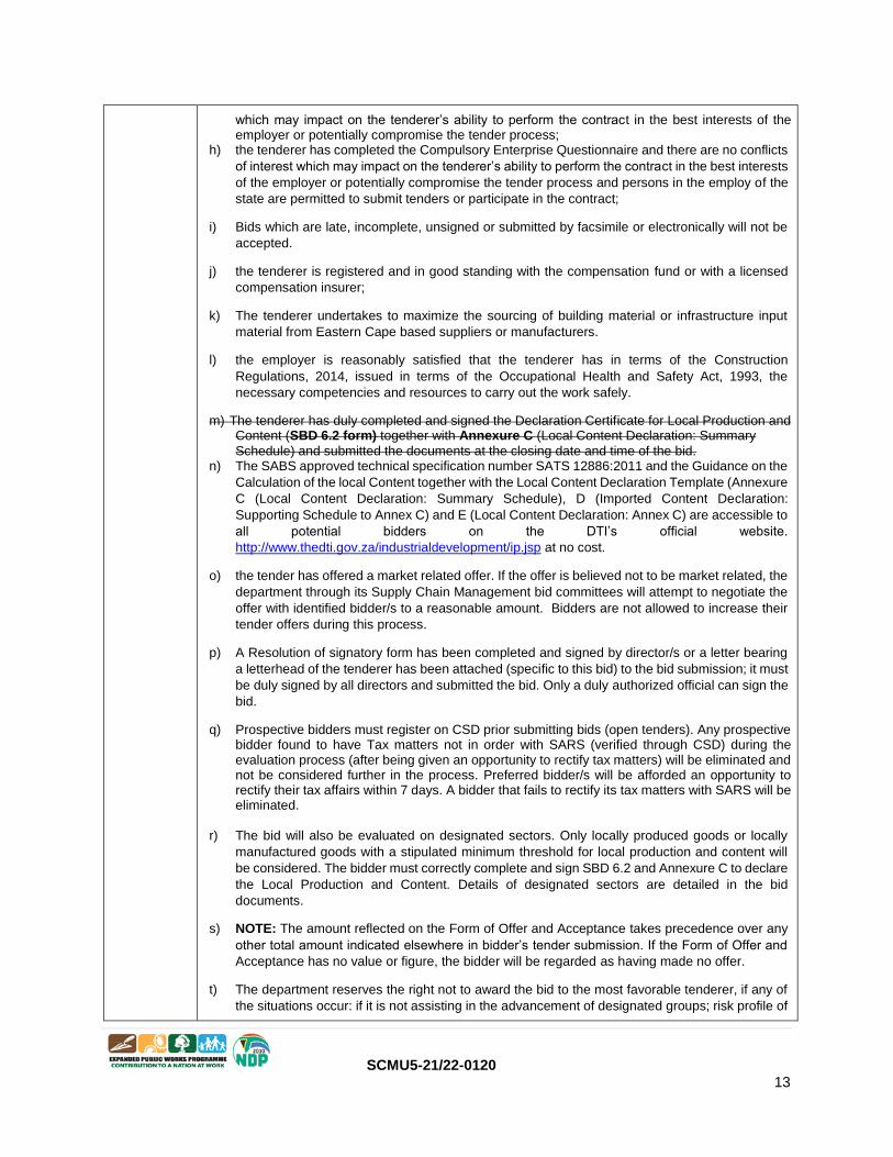
which may impact on the tenderer’s ability to perform the contract in the best interests of the employer or potentially compromise the tender process;
h) the tenderer has completed the Compulsory Enterprise Questionnaire and there are no conflicts
of interest which may impact on the tenderer’s ability to perform the contract in the best interests
of the employer or potentially compromise the tender process and persons in the employ of the
state are permitted to submit tenders or participate in the contract;
i) Bids which are late, incomplete, unsigned or submitted by facsimile or electronically will not be
accepted.
j) the tenderer is registered and in good standing with the compensation fund or with a licensed
compensation insurer;
k) The tenderer undertakes to maximize the sourcing of building material or infrastructure input
material from Eastern Cape based suppliers or manufacturers.
l) the employer is reasonably satisfied that the tenderer has in terms of the Construction
Regulations, 2014, issued in terms of the Occupational Health and Safety Act, 1993, the
necessary competencies and resources to carry out the work safely.
m) The tenderer has duly completed and signed the Declaration Certificate for Local Production and Content (SBD 6.2 form) together with Annexure C (Local Content Declaration: Summary
Schedule) and submitted the documents at the closing date and time of the bid. n) The SABS approved technical specification number SATS 12886:2011 and the Guidance on the
Calculation of the local Content together with the Local Content Declaration Template (Annexure
C (Local Content Declaration: Summary Schedule), D (Imported Content Declaration:
Supporting Schedule to Annex C) and E (Local Content Declaration: Annex C) are accessible to
all potential bidders on the DTI’s official website.
http://www.thedti.gov.za/industrialdevelopment/ip.jsp at no cost.
o) the tender has offered a market related offer. If the offer is believed not to be market related, the
department through its Supply Chain Management bid committees will attempt to negotiate the
offer with identified bidder/s to a reasonable amount. Bidders are not allowed to increase their
tender offers during this process.
p) A Resolution of signatory form has been completed and signed by director/s or a letter bearing
a letterhead of the tenderer has been attached (specific to this bid) to the bid submission; it must
be duly signed by all directors and submitted the bid. Only a duly authorized official can sign the
bid.
q) Prospective bidders must register on CSD prior submitting bids (open tenders). Any prospective bidder found to have Tax matters not in order with SARS (verified through CSD) during the evaluation process (after being given an opportunity to rectify tax matters) will be eliminated and not be considered further in the process. Preferred bidder/s will be afforded an opportunity to rectify their tax affairs within 7 days. A bidder that fails to rectify its tax matters with SARS will be eliminated.
r) The bid will also be evaluated on designated sectors. Only locally produced goods or locally
manufactured goods with a stipulated minimum threshold for local production and content will
be considered. The bidder must correctly complete and sign SBD 6.2 and Annexure C to declare
the Local Production and Content. Details of designated sectors are detailed in the bid
documents.
s) NOTE: The amount reflected on the Form of Offer and Acceptance takes precedence over any
other total amount indicated elsewhere in bidder’s tender submission. If the Form of Offer and
Acceptance has no value or figure, the bidder will be regarded as having made no offer.
t) The department reserves the right not to award the bid to the most favorable tenderer, if any of
the situations occur: if it is not assisting in the advancement of designated groups; risk profile of

SCMU5-21/22-0120 14
the favorable firm is too high; the bidder has been awarded a considerable number of projects
by the department or provincial government; has performed unsatisfactorily in the past, etc.
u) Contractor has committed to allocate and support SMMEs (EME /QSEs which are at least 51% owed by Black people) living in Amathole region. The work packages to be implemented by the local SMMEs are already set or allocated in the Bills of Quantities of the project as provisional sum that a contractor will price only Profit and Attendance for. The responsibility to sub-contract with competent and capable sub-contractor’s rests with the main contractor/supplier. Once awarded, to bring harmony on site, the department reserves the right to intervene in the selection of local sub-contractors or SMMEs on site.
5.13 The number of paper copies of the signed contract to be provided by the employer is 1.
The additional conditions of tender are:
Wherever a brand name is specified in this document (i.e. specifications, pricing schedule, bill of quantities or anywhere), the department requires an item similar/equivalent or better.
T.2.1
A. List of returnable documents
1 Documentation to demonstrate eligibility to have tenders evaluated I.e. List all documentation to
demonstrate eligibility to have a submission evaluated.
Appropriate CIDB grading suitable for the works (as stated in 4.1).
2 Returnable Schedules required for tender evaluation purposes
The tenderer must fully and appropriately complete and sign the following returnable schedules as relevant:
Record of Addenda to Tender Documents
Proposed amendments and qualifications
SBD 1, 4, 8, 9, 6.1
Form of Offer and Acceptance
Final Summary of Bills of Quantities or a complete Pricing Schedule
3 Other documents required for tender evaluation purposes
The tenderer must provide the following returnable documents:
And original or certified copy of a valid B-BBEE Verification certificate from a verification agency accredited by SANAS and recognized as an Accredited B-BBEE Verification Agencies (see www.sanas.co.za/directory/bbee_default.php) if preference points are claimed in respect of Broad-Based Black Economic Empowerment. A tenderer which is an EME or QSE can submit a duly signed original or certified copy of a Sworn Affidavit attested by a Commissioner of Oaths and attested by a Commissioner of Oaths Sworn Affidavit form. For an entity tendering as a joint venture, a valid consolidated B-B-BBEE Certificate meeting same requirements must be submitted with the bid. Failure to do so zero points will be allocated for B-BBEE status level.
A CSD Report for a contractor with valid and correct information.
4 Returnable Schedules that will be used for tender evaluation purposes and be incorporated into the contract
The tenderer must complete the following returnable documents:
A duly completed Annexure C and SBD 6.2
A duly completed form of Offer and Acceptance (and any revision of prices if there are
any).
5 Only authorized signatories may sign the original and all copies of the tender offer where required. In the case of a ONE‐PERSON CONCERN submitting a tender, this shall be clearly stated.

SCMU5-21/22-0120 15
In the case of a COMPANY submitting a tender, include a copy of a resolution by its board of directors authorizing a director or other official of the company to sign the documents on behalf of
the company. In the case of a CLOSE CORPORATION submitting a tender, include a copy of a resolution by its members authorizing a member or other official of the corporation to sign the documents on each
member’s behalf.
6 Information and data to be completed in all respects
Accept that tender offers, which do not provide all the data or information requested completely and in the form required, may be regarded by the employer as nonresponsive.
7 Canvassing and obtaining of additional information by tenderers
The Tenderer shall not make any attempt either directly or indirectly to canvass any of the Employer’s officials or the Employer’s agent in respect of his tender, after the opening of the tenders but prior to the Employer arriving at a decision thereon. The Tenderer shall not make any attempt to obtain particulars of any relevant information, other than that disclosed at the opening of tenders.
8 Prohibitions on awards to persons in service of the state
The Employer is prohibited to award a tender to a person ‐ a) who is in the service of the state; or
b) if that person is not a natural person, of which any director, manager, principal shareholder or stakeholder is a person in the service of the state; or
c) a person who is an advisor or consultant contracted with the Department or municipal entity. In the service of the state means to be ‐
a) a member of:‐
a any municipal council;
b any provincial legislature; or
c the National Assembly or the National Council of Provinces;
d) a member of the board of directors of any municipal entity;
e) an official of any Department or municipal entity;
f) an employee of any national or provincial department;
g) provincial public entity or constitutional institution within the meaning of the
Public Finance Management Act, 1999 (Act No.1 of 1999);
h) a member of the accounting authority of any national or provincial public entity; or
i) an employee of Parliament or a provincial legislature.
In order to give effect to the above, the questionnaire for the declaration of interests in the tender of persons in service of state in part T2 of this procurement document must be completed.
9 Awards to close family members of persons in the service of the state
Accept that the notes to the Employer’s annual financial statements must disclose particulars of any award of more than R2000 to a person who is a spouse, child or parent of a person in the service of the state (defined in clause 8 above), or has been in the service of the state in the previous twelve months, including ‐ a) the name of that person;
b) the capacity in which that person is in the service of the state; and
c) the amount of the award.
In order to give effect to the above, the questionnaire for the declaration of interests in the tender of persons in service of state in part T2 of this procurement document must be completed.

SCMU5-21/22-0120 16
10 Respond to requests from the tenderer
The employer will respond to requests for clarification up to 7 (seven) working days before the
tender closing time.
11 Opening of tender submissions
Tenders will be opened immediately after the closing time for tenders
12 Scoring quality / functionality: N/A
13 Cancellation and re‐invitation of tenders
An organ of state may, prior to the award of the tender, cancel the tender if‐
(a) due to changed circumstances, there is no longer a need for the services, works or goods
requested; or
(b) funds are no longer available to cover the total envisaged expenditure; or
(c) no acceptable tenders are received.
(d) Tender validity period has expired.
(e) Gross irregularities in the tender processes and/or tender documents.
(f) No market related offer received (after attempts of negotiation processes)
Where applicable, the decision to cancel the tender will be published in the CIDB website and in the
Tender Bulletin or the media in which the original tender invitation as advertised.
14 Dispute resolution mechanism will be done through the Adjudication route.
15 The department must when acting against the tenderer or person awarded the contract on a fraudulent basis, considers the provisions of Regulation 14: The remedies provided for in Preferential Procurement Regulations 2017 do not prevent an institution from instituting remedies arising from any other prescripts or contract.
15 Where the employer terminates the contract due to default of the contractor in whole or in part, the employer may decide to: a) Refer the breach in contract to the cidb for investigation as a breach of
the cidb Code of Conduct in terms of the cidb Regulations; or b) may impose a restriction penalty
on the contractor in terms of Section 14 of the Preferential Procurement Regulations. The outcomes
of such investigations in terms of both the cidb Regulations and the Preferential Procurement
Regulations may prohibit the contractor from doing business with the public sector for a period not
exceeding 10 years.

SCMU5-21/22-0120 17
T2.1 List of Returnable Documents
The tenderer must complete the following returnable documents:
1 Returnable Schedules required for quotation evaluation purposes
Compulsory enterprise questionnaire
Record of addenda issued (Only if addenda is issued)
Certificate of authority for joint ventures (Only where the tender/ quotation is submitted by a joint venture)
2 Other documents required for quotation evaluation purposes
Form of Offer and Acceptance
Final Summary (Bills of Quantities)
3 Returnable Schedules that will be incorporated into the contract
Details of the Project Team and CV with Qualifications & Proof of Registration completed for each individual of
proposed
Schedule of Plant and Equipment
Record of projects: current, past and on tender.
Project References – at least 3
SBD 1, 4, 6.1, 6.2, 8 and 9 and Annexure C (Local Production and Content)
Certified copy of B-BBEE Status Level Verification certificate OR a valid original or certified copy of a Sworn
Affidavit attested by a Commissioner of Oaths (Annexure B)
Sub contract agreement (where applicable) or intent to sub contract as per requirements.

SCMU5-21/22-0120 18
PART A
INVITATION TO BID
YOU ARE HEREBY INVITED TO BID FOR REQUIREMENTS OF THE (NAME OF DEPARTMENT/ PUBLIC ENTITY)
BID NUMBER: SCMU5-21/22-0120 CLOSING DATE: 31 August 2021 CLOSING TIME: 11:00
DESCRIPTION: SCHEDULED MAINTENANCE CONTRACT-BOILERS CENTRAL REGION
BID RESPONSE DOCUMENTS MAY BE DEPOSITED IN THE BID BOX SITUATED AT (STREET ADDRESS)
DEPARTMENT OF PUBLIC WORKS, FRONT CORNER OF QHASANA BUILDING ON THE WAY TO CIDB OFFICES LABELLED “TENDERS”, BHISHO.
BIDDING PROCEDURE ENQUIRIES MAY BE DIRECTED TO TECHNICAL ENQUIRIES MAY BE DIRECTED TO:
CONTACT PERSON Zamuxolo Billie CONTACT PERSON DUMISA MZOMBA
TELEPHONE NUMBER 040 602 4563 TELEPHONE NUMBER 040 602 4121
FACSIMILE NUMBER FACSIMILE NUMBER
E-MAIL ADDRESS [email protected] E-MAIL ADDRESS [email protected]
SUPPLIER INFORMATION
NAME OF BIDDER
POSTAL ADDRESS
STREET ADDRESS
TELEPHONE NUMBER CODE NUMBER
CELLPHONE NUMBER
FACSIMILE NUMBER CODE NUMBER
E-MAIL ADDRESS
VAT REGISTRATION NUMBER
SUPPLIER COMPLIANCE STATUS
TAX COMPLIANCE SYSTEM PIN:
OR
CENTRAL SUPPLIER DATABASE No: MAAA
B-BBEE STATUS LEVEL VERIFICATION CERTIFICATE
TICK APPLICABLE BOX]
Yes No
B-BBEE STATUS LEVEL SWORN AFFIDAVIT
[TICK APPLICABLE BOX]
Yes No
[A B-BBEE STATUS LEVEL VERIFICATION CERTIFICATE/ SWORN AFFIDAVIT (FOR EMES & QSEs) MUST BE SUBMITTED IN ORDER TO QUALIFY FOR PREFERENCE POINTS FOR B-BBEE]
a) ARE YOU THE ACCREDITED REPRESENTATIVE IN SOUTH AFRICA FOR THE GOODS /SERVICES /WORKS OFFERED?
Yes No [IF YES ENCLOSE PROOF]
b) ARE YOU A FOREIGN BASED SUPPLIER FOR THE GOODS /SERVICES /WORKS OFFERED?
Yes No [IF YES, COMPLETE QUESTIONNAIRE BELOW ]
QUESTIONNAIRE TO BIDDING FOREIGN SUPPLIERS
IS THE ENTITY A RESIDENT OF THE REPUBLIC OF SOUTH AFRICA (RSA)? YES NO
DOES THE ENTITY HAVE A BRANCH IN THE RSA? YES NO
DOES THE ENTITY HAVE A PERMANENT ESTABLISHMENT IN THE RSA? YES NO
DOES THE ENTITY HAVE ANY SOURCE OF INCOME IN THE RSA? YES NO
SBD 1

SCMU5-21/22-0120 19
IS THE ENTITY LIABLE IN THE RSA FOR ANY FORM OF TAXATION? YES NO IF THE ANSWER IS “NO” TO ALL OF THE ABOVE, THEN IT IS NOT A REQUIREMENT TO REGISTER FOR A TAX COMPLIANCE STATUS SYSTEM PIN CODE FROM THE SOUTH AFRICAN REVENUE SERVICE (SARS) AND IF NOT REGISTER AS PER 2.3 BELOW

SCMU5-21/22-0120 20
PART B
TERMS AND CONDITIONS FOR BIDDING
1. BID SUBMISSION:
1.1. BIDS MUST BE DELIVERED BY THE STIPULATED TIME TO THE CORRECT ADDRESS. LATE BIDS WILL NOT BE ACCEPTED FOR CONSIDERATION.
1.2. ALL BIDS MUST BE SUBMITTED ON THE OFFICIAL FORMS PROVIDED–(NOT TO BE RE-TYPED) OR IN THE MANNER PRESCRIBED IN THE BID DOCUMENT.
1.3. THIS BID IS SUBJECT TO THE PREFERENTIAL PROCUREMENT POLICY FRAMEWORK ACT, 2000 AND THE PREFERENTIAL PROCUREMENT REGULATIONS, 2017, THE GENERAL CONDITIONS OF CONTRACT (GCC) AND, IF APPLICABLE, ANY OTHER SPECIAL CONDITIONS OF CONTRACT.
1.4. THE SUCCESSFUL BIDDER WILL BE REQUIRED TO FILL IN AND SIGN A WRITTEN CONTRACT FORM (SBD7).
2. TAX COMPLIANCE REQUIREMENTS
2.1 BIDDERS MUST ENSURE COMPLIANCE WITH THEIR TAX OBLIGATIONS.
2.2 BIDDERS ARE REQUIRED TO SUBMIT THEIR UNIQUE PERSONAL IDENTIFICATION NUMBER (PIN) ISSUED BY SARS TO ENABLE THE ORGAN OF STATE TO VERIFY THE TAXPAYER’S PROFILE AND TAX STATUS.
2.3 APPLICATION FOR TAX COMPLIANCE STATUS (TCS) PIN MAY BE MADE VIA E-FILING THROUGH THE SARS WEBSITE WWW.SARS.GOV.ZA.
2.4 BIDDERS MAY ALSO SUBMIT A PRINTED TCS CERTIFICATE TOGETHER WITH THE BID.
2.5 IN BIDS WHERE CONSORTIA / JOINT VENTURES / SUB-CONTRACTORS ARE INVOLVED, EACH PARTY MUST SUBMIT A SEPARATE TCS CERTIFICATE / PIN / CSD NUMBER.
2.6 WHERE NO TCS IS AVAILABLE BUT THE BIDDER IS REGISTERED ON THE CENTRAL SUPPLIER DATABASE (CSD), A CSD NUMBER MUST BE PROVIDED.
2.7 NO BIDS WILL BE CONSIDERED FROM PERSONS IN THE SERVICE OF THE STATE, COMPANIES WITH DIRECTORS WHO ARE PERSONS IN THE SERVICE OF THE STATE, OR CLOSE CORPORATIONS WITH MEMBERS PERSONS IN THE SERVICE OF THE STATE.”
SIGNATURE OF BIDDER: …………………………………………… CAPACITY UNDER WHICH THIS BID IS SIGNED: …………………………………………… (Proof of authority must be submitted e.g. company resolution) DATE: …………………………………………...

SCMU5-21/22-0120 21
Compulsory Enterprise questionnaire
The following particulars must be furnished. In the case of a joint venture, separate enterprise questionnaires
in respect of each partner must be completed and submitted.
Section 1: Name of enterprise: . . . . . . . . . . . . . . . . . . . . . . . . . . . . . . . . . . . . . . . . . . . . . . . . . . . . . . . .
Section 2: VAT registration number, if any: . . . . . . . . . . . . . . . . . . . . . . . . . . . . . . . . . . . . . . . . . . . . . . . .
Section 3: cidb registration number, if any: . . . . . . . . . . . . . . . . . . . . . . . . . . . . . . . . . . . . . . . . . . . . . . .
Section 4: Particulars of sole proprietors and partners in partnerships
Name* Identity number* Personal income tax number*
* Complete only if sole proprietor or partnership and attach separate page if more than 3 partners
Section 5: Particulars of companies and close corporations
Company registration number . . . . . . . . . . . . . . . . . . . . . . . . . . . . . . . . . . . . . . . . . . . . . . . . . . . . . . . . . . .
Close corporation number . . . . . . . . . . . . . . . . . . . . . . . . . . . . . . . . . . . . . . . . . . . . . . . . . . . . . . . . . . . . . . Tax
reference number . . . . . . . . . . . . . . . . . . . . . . . . . . . . . . . . . . . . . . . . . . . . . . . . . . . . . . . . . . . . . . . . .
Section 6: The attached SBD 4 must be completed for each tender and be attached as a tender
requirement.
Section 7: The attached SBD 6.1 must be completed for each tender and be attached as a
requirement.
Section 8: The attached SBD 8 must be completed for each tender and be attached as a requirement.
Section 9: The attached SBD 9 must be completed for each tender and be attached as a requirement.
The undersigned, who warrants that he / she is duly authorised to do so on behalf of the enterprise: i) authorizes the Employer to obtain a tax clearance certificate from the South African Revenue Services
that my / our tax matters are in order; ii) confirms that the neither the name of the enterprise or the name of any partner, manager, director or other
person, who wholly or partly exercises, or may exercise, control over the enterprise appears on the Register of Tender Defaulters established in terms of the Prevention and Combating of Corrupt Activities Act of 2004; iii) confirms that no partner, member, director or other person, who wholly or partly
exercises, or may exercise, control over the enterprise appears, has within the last five years been convicted of fraud or corruption; iv) confirms that I / we are not associated, linked or involved with any other tendering entities submitting
tender offers and have no other relationship with any of the tenderers or those responsible for compiling the scope of work that could cause or be interpreted as a conflict of interest; and
iv) confirms that the contents of this questionnaire are within my personal knowledge and are to the best of
my belief both true and correct.
Signed Date
Name Position
Compulsory Enterprise
Questionannare
SCMU5-21/22-0120 22
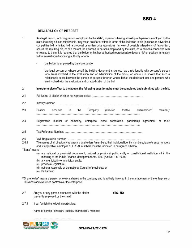
DECLARATION OF INTEREST 1. Any legal person, including persons employed by the state¹, or persons having a kinship with persons employed by the
state, including a blood relationship, may make an offer or offers in terms of this invitation to bid (includes an advertised competitive bid, a limited bid, a proposal or written price quotation). In view of possible allegations of favouritism, should the resulting bid, or part thereof, be awarded to persons employed by the state, or to persons connected with or related to them, it is required that the bidder or his/her authorised representative declare his/her position in relation to the evaluating/adjudicating authority where-
- the bidder is employed by the state; and/or - the legal person on whose behalf the bidding document is signed, has a relationship with persons/a person
who are/is involved in the evaluation and or adjudication of the bid(s), or where it is known that such a relationship exists between the person or persons for or on whose behalf the declarant acts and persons who are involved with the evaluation and or adjudication of the bid.
2. In order to give effect to the above, the following questionnaire must be completed and submitted with the bid. 2.1 Full Name of bidder or his or her representative: …………………………………………………. 2.2 Identity Number:……………………………………………………………………………………... 2.3 Position occupied in the Company (director, trustee, shareholder², member):
…………………………………………………………………………………………………………. 2.4 Registration number of company, enterprise, close corporation, partnership agreement or trust:
……………………………………………………………..………….………………………………. 2.5 Tax Reference Number: ……………………………………………………………………………… 2.6 VAT Registration Number: ……………………………………………………………………….... 2.6.1 The names of all directors / trustees / shareholders / members, their individual identity numbers, tax reference numbers
and, if applicable, employee / PERSAL numbers must be indicated in paragraph 3 below. ¹“State” means – (a) any national or provincial department, national or provincial public entity or constitutional institution within the
meaning of the Public Finance Management Act, 1999 (Act No. 1 of 1999); (b) any municipality or municipal entity; (c) provincial legislature; (d) national Assembly or the national Council of provinces; or (e) Parliament. ²”Shareholder” means a person who owns shares in the company and is actively involved in the management of the enterprise or
business and exercises control over the enterprise. 2.7 Are you or any person connected with the bidder YES / NO presently employed by the state? 2.7.1 If so, furnish the following particulars:
Name of person / director / trustee / shareholder/ member: ……....………………………………
SBD 4

SCMU5-21/22-0120 23
Name of state institution at which you or the person connected to the bidder is employed : ……….. ……………………………………… Position occupied in the state institution: ……………………………………… Any other particulars: ……………………………………………………………… ……………………………………………………………… ………………………………………………………………
2.7.2 If you are presently employed by the state, did you obtain YES / NO / N/A
the appropriate authority to undertake remunerative work outside employment in the public sector?
2.7.2.1 If yes, did you attach proof of such authority to the bid YES / NO / N/A
document? (Note: Failure to submit proof of such authority, where applicable, may result in the disqualification of the bid.
2.7.2.2 If no, furnish reasons for non-submission of such proof:
……………………………………………………………………. ……………………………………………………………………. …………………………………………………………………….
2.8 Did you or your spouse, or any of the company’s directors / YES / NO trustees / shareholders / members or their spouses conduct business with the state in the previous twelve months?
2.8.1 If so, furnish particulars:
………………………………………………………………….. ………………………………………………………………….. …………………………………………………………………...
2.9 Do you, or any person connected with the bidder, have YES / NO any relationship (family, friend, other) with a person employed by the state and who may be involved with the evaluation and or adjudication of this bid?
2.9.1 If so, furnish particulars. ……………………………………………………………... …………………………………………………………..….
………………………………………………………………
2.10 Are you, or any person connected with the bidder, YES/NO aware of any relationship (family, friend, other) between
any other bidder and any person employed by the state who may be involved with the evaluation and or adjudication of this bid?
2.10.1 If so, furnish particulars.

SCMU5-21/22-0120 24
……………………………………………………………… ……………………………………………………………… ………………………………………………………………
2.11 Do you or any of the directors / trustees / shareholders / members YES/NO of the company have any interest in any other related companies whether or not they are bidding for this contract?
2.11.1 If so, furnish particulars: ……………………………………………………………………………. ……………………………………………………………………………. …………………………………………………………………………….
3 Full details of directors / trustees / members / shareholders.
Full Name Identity Number Personal Income Tax Reference Number
State Employee Number / Persal Number
4 DECLARATION
I, THE UNDERSIGNED (NAME)………………………………………………………………………
CERTIFY THAT THE INFORMATION FURNISHED IN PARAGRAPHS 2 and 3 ABOVE IS CORRECT.
I ACCEPT THAT THE STATE MAY REJECT THE BID OR ACT AGAINST ME SHOULD THIS DECLARATION PROVE TO
BE FALSE.
………………………………….. ..…………………………………………… Signature Date …………………………………. ……………………………………………… Position Name of bidder
SCMU5-21/22-0120 25
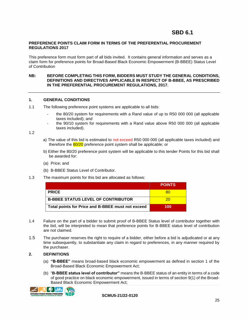
SBD 6.1 PREFERENCE POINTS CLAIM FORM IN TERMS OF THE PREFERENTIAL PROCUREMENT REGULATIONS 2017 This preference form must form part of all bids invited. It contains general information and serves as a claim form for preference points for Broad-Based Black Economic Empowerment (B-BBEE) Status Level of Contribution NB: BEFORE COMPLETING THIS FORM, BIDDERS MUST STUDY THE GENERAL CONDITIONS,
DEFINITIONS AND DIRECTIVES APPLICABLE IN RESPECT OF B-BBEE, AS PRESCRIBED IN THE PREFERENTIAL PROCUREMENT REGULATIONS, 2017.
1. GENERAL CONDITIONS
1.1 The following preference point systems are applicable to all bids:
- the 80/20 system for requirements with a Rand value of up to R50 000 000 (all applicable taxes included); and
- the 90/10 system for requirements with a Rand value above R50 000 000 (all applicable taxes included).
1.2
a) The value of this bid is estimated to not exceed R50 000 000 (all applicable taxes included) and therefore the 80/20 preference point system shall be applicable; or
b) Either the 80/20 preference point system will be applicable to this tender Points for this bid shall be awarded for:
(a) Price; and
(b) B-BBEE Status Level of Contributor.
1.3 The maximum points for this bid are allocated as follows:
POINTS
PRICE 80
B-BBEE STATUS LEVEL OF CONTRIBUTOR 20
Total points for Price and B-BBEE must not exceed 100
1.4 Failure on the part of a bidder to submit proof of B-BBEE Status level of contributor together with the bid, will be interpreted to mean that preference points for B-BBEE status level of contribution are not claimed.
1.5 The purchaser reserves the right to require of a bidder, either before a bid is adjudicated or at any time subsequently, to substantiate any claim in regard to preferences, in any manner required by the purchaser.
2. DEFINITIONS
(a) “B-BBEE” means broad-based black economic empowerment as defined in section 1 of the Broad-Based Black Economic Empowerment Act;
(b) “B-BBEE status level of contributor” means the B-BBEE status of an entity in terms of a code of good practice on black economic empowerment, issued in terms of section 9(1) of the Broad-Based Black Economic Empowerment Act;

SCMU5-21/22-0120 26
(c) “bid” means a written offer in a prescribed or stipulated form in response to an invitation by an organ of state for the provision of goods or services, through price quotations, advertised competitive bidding processes or proposals;
(d) “Broad-Based Black Economic Empowerment Act” means the Broad-Based Black Economic Empowerment Act, 2003 (Act No. 53 of 2003);
(e) “EME” means an Exempted Micro Enterprise in terms of a code of good practice on black economic empowerment issued in terms of section 9 (1) of the Broad-Based Black Economic Empowerment Act;
(f) “functionality” means the ability of a tenderer to provide goods or services in accordance with specifications as set out in the tender documents.
(g) “prices” includes all applicable taxes less all unconditional discounts;
(h) “proof of B-BBEE status level of contributor” means:
1) B-BBEE Status level certificate issued by an authorized body or person;
2) A sworn affidavit as prescribed by the B-BBEE Codes of Good Practice;
3) Any other requirement prescribed in terms of the B-BBEE Act;
(i) “QSE” means a qualifying small business enterprise in terms of a code of good practice on black economic empowerment issued in terms of section 9 (1) of the Broad-Based Black Economic Empowerment Act;
(j) “rand value” means the total estimated value of a contract in Rand, calculated at the time of bid invitation, and includes all applicable taxes;
3. POINTS AWARDED FOR PRICE
3.1 THE 80/20 OR 90/10 PREFERENCE POINT SYSTEMS
A maximum of 80 or 90 points is allocated for price on the following basis: 80/20 or 90/10
min
min180
P
PPtPs or
min
min190
P
PPtPs
Where
Ps = Points scored for price of bid under consideration
Pt = Price of bid under consideration
Pmin = Price of lowest acceptable bid
4. POINTS AWARDED FOR B-BBEE STATUS LEVEL OF CONTRIBUTOR
4.1 In terms of Regulation 6 (2) and 7 (2) of the Preferential Procurement Regulations, preference points must be awarded to a bidder for attaining the B-BBEE status level of contribution in accordance
with the table below:

SCMU5-21/22-0120 27
B-BBEE Status Level of Contributor
Number of points
(90/10 system)
Number of points
(80/20 system)
1 10 20
2 9 18
3 6 14
4 5 12
5 4 8
6 3 6
7 2 4
8 1 2
Non-compliant contributor 0 0
5. BID DECLARATION
5.1 Bidders who claim points in respect of B-BBEE Status Level of Contribution must complete the following:
6. B-BBEE STATUS LEVEL OF CONTRIBUTOR CLAIMED IN TERMS OF PARAGRAPHS 1.4 AND 4.1
6.1 B-BBEE Status Level of Contributor: . = ………(maximum of 10 or 20 points)
(Points claimed in respect of paragraph 7.1 must be in accordance with the table reflected in paragraph 4.1 and must be substantiated by relevant proof of B-BBEE status level of contributor.
7. SUB-CONTRACTING
7.1 Will any portion of the contract be sub-contracted?
(Tick applicable box)
YES NO
7.1.1 If yes, indicate:
i) What percentage of the contract will be subcontracted............…………….…………% ii) The name of the sub-contractor………………………………………………………….. iii) The B-BBEE status level of the sub-contractor......................................…………….. iv) Whether the sub-contractor is an EME or QSE
(Tick applicable box)
YES NO
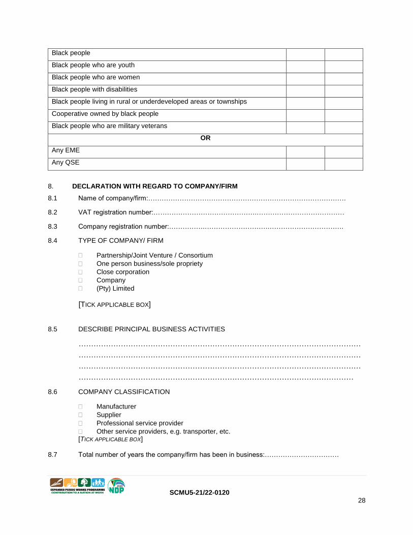
Specify, by ticking the appropriate box, if subcontracting with an enterprise in terms of Preferential Procurement Regulations, 2017:
Designated Group: An EME or QSE which is at last 51% owned by: EME
√
QSE
√
SCMU5-21/22-0120 28
Black people
Black people who are youth
Black people who are women
Black people with disabilities
Black people living in rural or underdeveloped areas or townships
Cooperative owned by black people
Black people who are military veterans
OR
Any EME
Any QSE
8. DECLARATION WITH REGARD TO COMPANY/FIRM
8.1 Name of company/firm:…………………………………………………………………………….
8.2 VAT registration number:……………………………………….…………………………………
8.3 Company registration number:…………….……………………….…………………………….
8.4 TYPE OF COMPANY/ FIRM
Partnership/Joint Venture / Consortium
One person business/sole propriety
Close corporation
Company
(Pty) Limited
[TICK APPLICABLE BOX]
8.5 DESCRIBE PRINCIPAL BUSINESS ACTIVITIES
……………………………………………………………………………………………………
……………………………………………………………………………………………………
……………………………………………………………………………………………………
…………………………………………………………………………………………………
8.6 COMPANY CLASSIFICATION
Manufacturer
Supplier
Professional service provider
Other service providers, e.g. transporter, etc. [TICK APPLICABLE BOX]
8.7 Total number of years the company/firm has been in business:……………………………
SCMU5-21/22-0120 29
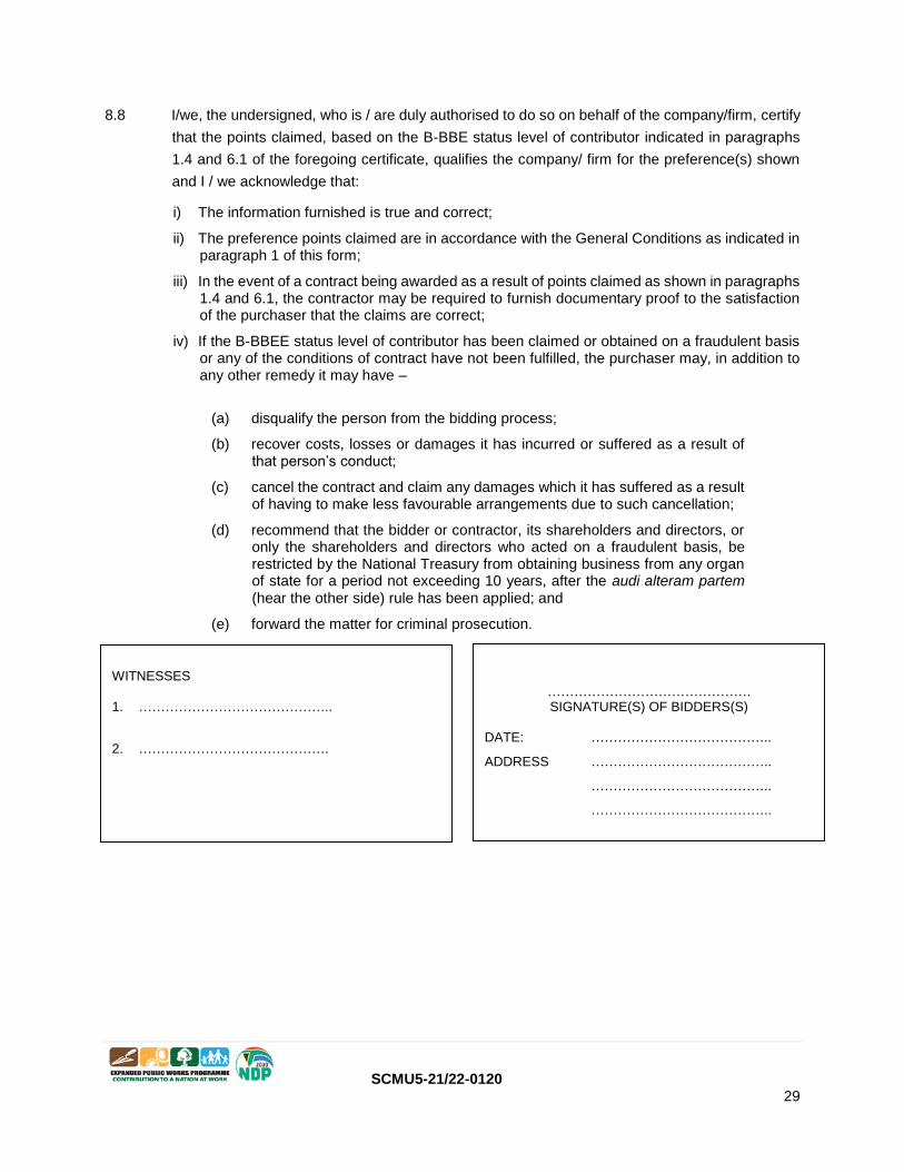
8.8 I/we, the undersigned, who is / are duly authorised to do so on behalf of the company/firm, certify
that the points claimed, based on the B-BBE status level of contributor indicated in paragraphs
1.4 and 6.1 of the foregoing certificate, qualifies the company/ firm for the preference(s) shown
and I / we acknowledge that:
i) The information furnished is true and correct;
ii) The preference points claimed are in accordance with the General Conditions as indicated in paragraph 1 of this form;
iii) In the event of a contract being awarded as a result of points claimed as shown in paragraphs 1.4 and 6.1, the contractor may be required to furnish documentary proof to the satisfaction of the purchaser that the claims are correct;
iv) If the B-BBEE status level of contributor has been claimed or obtained on a fraudulent basis or any of the conditions of contract have not been fulfilled, the purchaser may, in addition to any other remedy it may have –
(a) disqualify the person from the bidding process;
(b) recover costs, losses or damages it has incurred or suffered as a result of that person’s conduct;
(c) cancel the contract and claim any damages which it has suffered as a result of having to make less favourable arrangements due to such cancellation;
(d) recommend that the bidder or contractor, its shareholders and directors, or only the shareholders and directors who acted on a fraudulent basis, be restricted by the National Treasury from obtaining business from any organ of state for a period not exceeding 10 years, after the audi alteram partem (hear the other side) rule has been applied; and
(e) forward the matter for criminal prosecution.
………………………………………. SIGNATURE(S) OF BIDDERS(S)
DATE: …………………………………..
ADDRESS …………………………………..
…………………………………..
…………………………………..
WITNESSES 1. ……………………………………..
2. …………………………………….

SCMU5-21/22-0120 30
DECLARATION OF BIDDER’S PAST SUPPLY CHAIN MANAGEMENT PRACTICES
1 This Standard Bidding Document must form part of all bids invited.
2 It serves as a declaration to be used by institutions in ensuring that when goods and services are being
procured, all reasonable steps are taken to combat the abuse of the supply chain management system.
3 The bid of any bidder may be disregarded if that bidder, or any of its directors have-
a. abused the institution’s supply chain management system;
b. committed fraud or any other improper conduct in relation to such system; or
c. failed to perform on any previous contract.
4 In order to give effect to the above, the following questionnaire must be completed and submitted
with the bid.
Item Question Yes No
4.1 Is the bidder or any of its directors listed on the National Treasury’s database as
companies or persons prohibited from doing business with the public sector?
(Companies or persons who are listed on this database were informed in writing
of this restriction by the National Treasury after the audi alteram partem rule was
applied).
Yes
No
4.1.1 If so, furnish particulars:
4.2 Is the bidder or any of its directors listed on the Register for Tender Defaulters in
terms of section 29 of the Prevention and Combating of Corrupt Activities Act (No 12
of 2004)?
To access this Register enter the National Treasury’s website,
www.treasury.gov.za, click on the icon “Register for Tender Defaulters” or submit
your written request for a hard copy of the Register to facsimile number (012)
3265445.
Yes
No
4.2.1 If so, furnish particulars:
4.3 Was the bidder or any of its directors convicted by a court of law (including a court
outside of the Republic of South Africa) for fraud or corruption during the past five
years?
Yes
No
4.3.1 If so, furnish particulars:
4.4 Was any contract between the bidder and any organ of state terminated during the past
five years on account of failure to perform on or comply with the contract?
Yes
No
4.4.1 If so, furnish particulars:
CERTIFICATION
I, THE UNDERSIGNED (FULL NAME) …………………………………………………
CERTIFY THAT THE INFORMATION FURNISHED ON THIS DECLARATION FORM IS TRUE AND
CORRECT.
I ACCEPT THAT, IN ADDITION TO CANCELLATION OF A CONTRACT, ACTION MAY BE TAKEN
AGAINST ME SHOULD THIS DECLARATION PROVE TO BE FALSE.
SBD 8

SCMU5-21/22-0120 31
………………………………………... …………………………..
Signature Date
………………………………………. …………………………..
Position Name of Bidder

SCMU5-21/22-0120 32
CERTIFICATE OF INDEPENDENT BID DETERMINATION
1 This Standard Bidding Document (SBD) must form part of all bids¹ invited.
2 Section 4 (1) (b) (iii) of the Competition Act No. 89 of 1998, as amended, prohibits an agreement
between, or concerted practice by, firms, or a decision by an association of firms, if it is between
parties in a horizontal relationship and if it involves collusive bidding (or bid rigging). ² Collusive
bidding is a pe se prohibition meaning that it cannot be justified under any grounds.
3 Treasury Regulation 16A9 prescribes that accounting officers and accounting authorities must take all reasonable steps to prevent abuse of the supply chain management system and authorizes accounting officers and accounting authorities to:
a. disregard the bid of any bidder if that bidder, or any of its directors have abused the
institution’s supply chain management system and or committed fraud or any other improper conduct in relation to such system.
b. cancel a contract awarded to a supplier of goods and services if the supplier committed any
corrupt or fraudulent act during the bidding process or the execution of that contract.
4 This SBD serves as a certificate of declaration that would be used by institutions to ensure that,
when bids are considered, reasonable steps are taken to prevent any form of bid-rigging.
5 In order to give effect to the above, the attached Certificate of Bid Determination (SBD 9) must be
completed and submitted with the bid:
¹ Includes price quotations, advertised competitive bids, limited bids and proposals.
² Bid rigging (or collusive bidding) occurs when businesses, that would otherwise be expected to compete, secretly conspire to raise prices
or lower the quality of goods and / or services for purchasers who wish to acquire goods and / or services through a bidding process. Bid
rigging is, therefore, an agreement between competitors not to compete.
SBD 9
SCMU5-21/22-0120 33
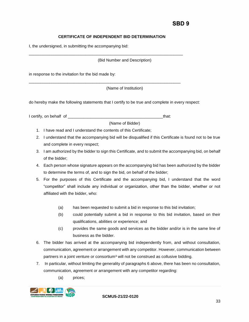
CERTIFICATE OF INDEPENDENT BID DETERMINATION
I, the undersigned, in submitting the accompanying bid:
____________________________________________________________________
(Bid Number and Description)
in response to the invitation for the bid made by:
___________________________________________________________________
(Name of Institution)
do hereby make the following statements that I certify to be true and complete in every respect:
I certify, on behalf of __________________________________________that:
(Name of Bidder)
1. I have read and I understand the contents of this Certificate;
2. I understand that the accompanying bid will be disqualified if this Certificate is found not to be true
and complete in every respect;
3. I am authorized by the bidder to sign this Certificate, and to submit the accompanying bid, on behalf
of the bidder;
4. Each person whose signature appears on the accompanying bid has been authorized by the bidder
to determine the terms of, and to sign the bid, on behalf of the bidder;
5. For the purposes of this Certificate and the accompanying bid, I understand that the word
“competitor” shall include any individual or organization, other than the bidder, whether or not
affiliated with the bidder, who:
(a) has been requested to submit a bid in response to this bid invitation;
(b) could potentially submit a bid in response to this bid invitation, based on their
qualifications, abilities or experience; and
(c) provides the same goods and services as the bidder and/or is in the same line of
business as the bidder.
6. The bidder has arrived at the accompanying bid independently from, and without consultation,
communication, agreement or arrangement with any competitor. However, communication between
partners in a joint venture or consortium³ will not be construed as collusive bidding.
7. In particular, without limiting the generality of paragraphs 6 above, there has been no consultation,
communication, agreement or arrangement with any competitor regarding:
(a) prices;
SBD 9

SCMU5-21/22-0120 34
(b) geographical area where product or service will be rendered (market allocation)
(c) methods, factors or formulas used to calculate prices;
(d) the intention or decision to submit or not to submit, a bid;
(e) the submission of a bid which does not meet the specifications and conditions of
the bid; or
(f) bidding with the intention not to win the bid.
8. In addition, there have been no consultations, communications, agreements or arrangements with
any competitor regarding the quality, quantity, specifications and conditions or delivery particulars
of the products or services to which this bid invitation relates.
9. The terms of the accompanying bid have not been, and will not be, disclosed by the bidder, directly
or indirectly, to any competitor, prior to the date and time of the official bid opening or of the awarding
of the contract.
³ Joint venture or Consortium means an association of persons for the purpose of combining their expertise, property, capital, efforts, skill and knowledge in an activity for the execution of a contract.
10. I am aware that, in addition and without prejudice to any other remedy provided to combat any
restrictive practices related to bids and contracts, bids that are suspicious will be reported to the
Competition Commission for investigation and possible imposition of administrative penalties in
terms of section 59 of the Competition Act No 89 of 1998 and or may be reported to the National
Prosecuting Authority (NPA) for criminal investigation and or may be restricted from conducting
business with the public sector for a period not exceeding ten (10) years in terms of the Prevention
and Combating of Corrupt Activities Act No 12 of 2004 or any other applicable legislation.
………………………………………… …………………………………
Signature Date
…………………………………………. …………………………………
Position Name of Bidder

SCMU5-21/22-0120 35
VALID ORIGINAL OR CERTIFIED COPY OF B-BBEE CERTIFICATE
(IF APPLICABLE, ATTACH HERE)

SCMU5-21/22-0120 36
SWORN AFFIDAVIT
(IF APPLICABLE, CHOOSE THE CORRECT FORM AND COMPLETE)
NB:CHOOSE ONE i.e EME or QSE!!!!)

SCMU5-21/22-0120 37
SWORN AFFIDAVIT – B-BBEE EXEMPTED MICRO ENTERPRISE (EME) – CONTRACTORS
I, the undersigned,
Full name & Surname
Identity number
Hereby declare under oath as follows:
1. The contents of this statement are to the best of my knowledge a true reflection of the facts.
2. I am a Member / Director / Owner of the following enterprise and am duly authorized to
act on its behalf:
Enterprise Name:
Trading Name (If
Applicable):
Registration Number:
Enterprise Physical
Address:
Type of Entity (CC,
(Pty) Ltd, Sole Prop
etc.):
Nature of Business:
Definition of “Black
People”
As per the Broad-Based Black Economic Empowerment Act 53 of
2003 as Amended by Act No 46 of 2013 “Black People” is a generic
term which means Africans, Coloureds and Indians –
(a) Who are citizens of the Republic of South Africa by birth or descent;
or
(b) Who became citizens of the Republic of South
Africa by naturalization-
i. Before 27 April 1994; or
ii. On or after 27 April 1994 and who would have been
entitled to acquire citizenship by naturalization prior
to that
date
3. I hereby declare under Oath that:
The Enterprise is % Black Owned as per Amended Code Series CSC000 of
the
Revised Construction Sector Codes of Good Practice issued under section 9 (1) of B-BBEE Act
No 53 of 2003 as Amended by Act No 46 of 2013,
The Enterprise is % Black Woman Owned as per Amended Code Series
CSC000 of the Revised Construction Sector Codes of Good Practice issued under section
9 (1) of B-BBEE Act No 53 of 2003 as Amended by Act No 46 of 2013,
The Enterprise is % Black Designated Group Owned as per Amended
Based on the Financial Statements/Management Accounts and other information available on the latest financial year-end of , (month & year), the annual Total Revenue not exceeding 10 million (ten Million Rands

SCMU5-21/22-0120 38
Based on the Financial Statements/Management Accounts and other information available on the latest financial year-end of_ ( month& year), the annual Total Revenue was equal to/or less than R10,000,000.00 (ten Million Rands or less),
Please confirm on the table below the B-BBEE level contributor, by ticking
the applicable box.
100% Black Owned Level One (135% B-BBEE procurement
recognition level)
At least 51% Black Owned but less
than 100% black owned
Level Two (125% B-BBEE
procurement recognition level)
At least 30% Black Owned but less
than 51% black owned
Level Four (100% B-BBEE
procurement recognition level)
Less than 30% Black Owned Level Five (80% B-BBEE procurement
recognition level)
NB: KEY NOTES FOR EMES (extract from Gazette No. 41287)
3.6.2.4.1 An Exempted Micro Enterprise (EME) with a total annual revenue of less than R1.8 million in the case of BEPs and less than R3 million in the case of Contractors are :
o A) Not subject to the discounting principle and therefore do not have to comply with the QSE Skills Development element, and
o B) Not required to have an authorised B-BBEE verification certificate, and may present an affidavit or a certificate issued by the Companies and Intellectual Property Commission (CIPC), in respect of their ownership and annual turnover.
Contractors and/Built Environment Professionals are encouraged to familiarize themselves with the Construction Sector Codes (CSC000) as issued through Government Gazette No. 41287, Board No. NOTICE 931 OF 2017. Details are available on: www.thedti.gov.za/economic_empowernment/bee_sector_charters.jsp
An electronic copy can also be requested through DPW offices (Supply Chain Offices)
4. I know and understand the contents of this affidavit and I have no objection to take the prescribed oath and consider the oath binding on my conscience and on the owners of the enterprise which I represent in this matter.
5. The sworn affidavit will be valid for a period of 12 months from the date signed by commissioner.
Deponent Signature: ____________________________________Date:
Commissioner of Oaths
Signature & stamp

SCMU5-21/22-0120 39
SWORN AFFIDAVIT – B-BBEE QUALIFYING SMALL ENTERPRISE (QSE) – CONTRACTORS
I, the undersigned,
Full name & Surname Identity number
Hereby declare under oath as follows:
1. The contents of this statement are to the best of my knowledge a true reflection of the facts.
2. I am a Member / Director / Owner of the following enterprise and am duly authorised to act on its behalf:
Enterprise Name:
Trading Name (If
Applicable):
Registration Number:
Enterprise Physical
Address:
Type of Entity (CC,
(Pty) Ltd, Sole Prop
etc.):
Nature of Business:
Definition of “Black
People”
As per the Broad-Based Black Economic Empowerment Act 53 of
2003 as Amended by Act No 46 of 2013 “Black People” is a generic
term which means Africans, Coloureds and Indians –
(a) Who are citizens of the Republic of South Africa by birth or descent;
or
(b) Who became citizens of the Republic of South
Africa by naturalization-
i. Before 27 April 1994; or
ii. On or after 27 April 1994 and who would have been
entitled to acquire citizenship by naturalization prior
to that
date
3. I hereby declare under Oath that:
The Enterprise is % Black Owned as per Amended Code Series CSC000 of
the
Revised Construction Sector Codes of Good Practice issued under section 9 (1) of B-BBEE Act
No 53 of 2003 as
Amended by Act No 46 of 2013,
The Enterprise is % Black Woman Owned as per Amended Code Series
CSC000 of the Revised Construction Sector Codes of Good Practice issued under section
9 (1) of B-BBEE Act No 53 of 2003 as Amended by Act No 46 of 2013,
The Enterprise is % Black Designated Group Owned as per

SCMU5-21/22-0120 40
Amended Code Series CSC000 of the Revised Construction Sector Codes of Good Practice issued under section 9 (1) of B-BBEE Act No 53 of 2003 as Amended by Act No 46 of 2013,
Based on the Financial Statements/Management Accounts and other information available on the latest financial year-end of , (month & year), the annual Total Revenue was between 10 million (ten Million Rands) and less than R50,000,000.00 (fifty Million Rands).
Please confirm on the table below the B-BBEE level contributor, by ticking
the applicable box.
100% Black Owned Level One (135% B-BBEE procurement
recognition level)
At least 51% Black Owned but
less than 100% black owned
Level Two (125% B-BBEE procurement
recognition level)
NB: KEY NOTES FOR QSE (extract from Gazette No. 41287)
5.6.3 A QSE that is at least 51% Black Owned or 100% Black Owned that does not comply with paragraph 3.6.2.3 above, will be discounted by one level from that level awarded in paragraphs 5.3.1 and 5.3.2 respectively.
5.3.4 Despite paragraphs 5.2, 5.3.1 and 5.3.2, an at least 51% Black Owned QSE’s B-BBEE Status Level and corresponding B-BBEE Recognition Level will be enhanced by one level if it achieves full points (excluding the bonus points) for the Skills Development element of the QSE Scorecard (paragraphs 1.1, 1.2 and 1.3 of Statement CSC603) or the Preferential Procurement and Supplier Development element of the QSE Scorecard (paragraphs 1.1, 1.2, 1.3 and 2.1 of CSC604).
5.3.5 For the avoidance of doubt, a Measured Entity that is measured in terms of the full QSE scorecard is not eligible for enhancement in terms of paragraph 5.3.4 above.
Contractors and/Built Environment Professionals are encouraged to familiarize themselves with
the Construction Sector Codes (CSC000) as issued through Government Gazette No. 41287, Board No. NOTICE 931 OF 2017. Details are available on: www.thedti.gov.za/economic_empowernment/bee_sector_charters.jsp
An electronic copy can also be requested through DPW offices (Supply Chain Offices)
4. I know and understand the contents of this affidavit and I have no objection to take the prescribed oath and consider the oath binding on my conscience and on the owners of the enterprise which I represent in this matter.
5. The sworn affidavit will be valid for a period of 12 months from the date signed by commissioner.
Deponent Signature: __________________________________Date:
Commissioner of Oaths
Signature & stamp

SCMU5-21/22-0120 41
PROOF OF REGISTRATION ON THE NATIONAL TREASURY CENTRAL SUPPLIER DATABASE (CSD REPORT)
(ATTACH HERE)

SCMU5-21/22-0120 42
VALID CIDB CERTIFICATE OF A TENDERER
(ATTACH HERE)
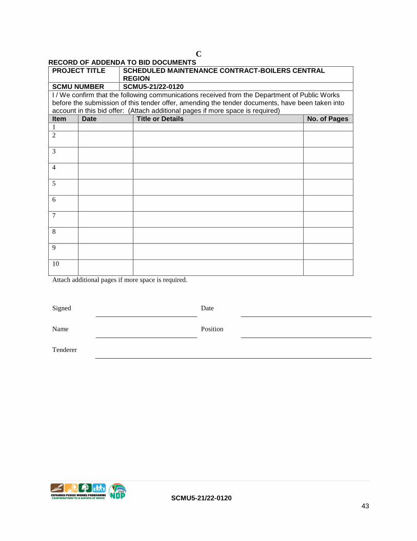
SCMU5-21/22-0120 43
C RECORD OF ADDENDA TO BID DOCUMENTS
PROJECT TITLE SCHEDULED MAINTENANCE CONTRACT-BOILERS CENTRAL REGION
SCMU NUMBER SCMU5-21/22-0120
I / We confirm that the following communications received from the Department of Public Works before the submission of this tender offer, amending the tender documents, have been taken into account in this bid offer: (Attach additional pages if more space is required)
Item Date Title or Details No. of Pages
1
2
3
4
5
6
7
8
9
10
Attach additional pages if more space is required.
Signed
Date
Name
Position
Tenderer

SCMU5-21/22-0120 44
D PROPOSED AMENDMENTS AND QUALIFICATIONS
The Tenderer should record any deviations or qualifications he may wish to make to the tender documents in this Returnable Schedule. Alternatively, a tenderer may state such deviations and qualifications in a covering letter to his tender and reference such letter in this schedule.
The Tenderer’s attention is drawn to clause 5.8 of SANS 10845-3 regarding the employer’s handling of material deviations and qualifications.
PROJECT TITLE SCHEDULED MAINTENANCE CONTRACT -BOILERS CENTRAL REGION
SCMU NUMBER SCMU5-21/22-0120
Page Clause /Item Proposal
The undersigned, who warrants that she/ he is duly authorised to do so on behalf of the enterprise, confirms that the content of this schedule that presented by the tenderer are within my personal knowledge and are to the best of my knowledge both true and correct
Signed
Date
Name Position
Enterprise name

SCMU5-21/22-0120 45
E
RESOLUTION FOR SIGNATORY
A: CERTIFICATE OF AUTHORITY FOR SIGNATORY
Signatory for companies shall confirm their authority hereto by attaching a duly signed and dated copy of the relevant resolution of the board of directors to this form or on company letter head.
An example is given below:
“By resolution of the board of directors passed at a meeting held on
Mr/Ms , whose signature appears below, has been duly authorised to
sign all documents in connection with the tender for Contract No.
and any Contract which may arise there from on behalf of (Block Capitals)
SIGNED ON BEHALF OF THE COMPANY:
IN HIS/HER CAPACITY AS:
DATE:
SIGNATURE OF SIGNATORY:
WITNESSES:
DIRECTOR (NAMES)
SIGNATURE
DIRECTOR (NAMES)
SIGNATURE
DIRECTOR (NAMES)
SIGNATURE
DIRECTOR (NAMES)
SIGNATURE
DIRECTOR (NAMES)
SIGNATURE
DIRECTOR (NAMES)
SIGNATURE
If you cannot complete this form, attach a separate sheet (in a company letter head, project specific and signed by all directors):

SCMU5-21/22-0120 46
F CERTIFICATE OF AUTHORITY FOR JOINT VENTURES
This Returnable Schedule is to be completed by joint ventures.
We, the undersigned, are submitting this tender offer in Joint Venture and hereby authorise Mr/Ms . . . . . . . . . . . . . . . . . . . . . . . . . . . . . . . . . . . ...., authorised signatory of the company . . . . . . . . . . . . . . . . . . . . . . . . . . . . . . . . . . . . . . . . . . . . . . . . . . . . . . . . . . . . . . . . . .. , acting in the capacity of lead partner, to sign all documents in connection with the tender offer and any contract resulting from it on our behalf.
PROJECT TITLE SCHEDULED MAINTENANCE CONTRACT -BOILERS CENTRAL REGION
SCMU NUMBER SCMU5-21/22-0120
NAME OF FIRM ADDRESS DULY AUTHORISED SIGNATORY
Lead partner:
…………………………………
.
Signature. . ……….. . . . . . . . . . . Name ………………………………....
Designation………………………………
…………………………………
.
Signature. . ……….. . . . . . . . . . . Name ………………………………....
Designation………………………………
…………………………………
.
Signature. . ……….. . . . . . . . . . . Name ………………………………....
Designation………………………………
…………………………………
.
Signature. . ……….. . . . . . . . . . . Name ………………………………....
Designation………………………………
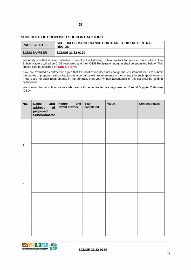
SCMU5-21/22-0120 47
G
SCHEDULE OF PROPOSED SUBCONTRACTORS
PROJECT TITLE SCHEDULED MAINTENANCE CONTRACT -BOILERS CENTRAL REGION
SCMU NUMBER SCMU5-21/22-0120
We notify you that it is our intention to employ the following Subcontractors for work in this contract. The Subcontractors will all be CIDB registered and their CIDB Registration number shall be submitted below. This should also be declared on SBD 6.1 form.
If we are awarded a contract we agree that this notification does not change the requirement for us to submit the names of proposed subcontractors in accordance with requirements in the contract for such appointments. If there are no such requirements in the contract, then your written acceptance of this list shall be binding between us.
We confirm that all subcontractors who are or to be contracted are registered on Central Supplier Database (CSD).
No. Name and address of proposed Subcontractor
Nature and extent of work
Year completed
Value Contact details
1
2
3

SCMU5-21/22-0120 48
4
5
The undersigned, who warrants that she/ he is duly authorised to do so on behalf of the enterprise, confirms that the content of this schedule that presented by the tenderer are within my personal knowledge and are to the best of my knowledge both true and correct
Signed
Date
Name Position
Enterprise name

SCMU5-21/22-0120 49
H
Evaluation schedule 1: Expertise of key personnel & CV’s
The experience of the key persons who will be responsible on behalf of the contractor for the management
of the project and the project team will be evaluated in relation to her/ his academic and qualifications
and experience.
Please Note:
1. The Respondent must complete the CV template provided in this document for each personnel it
intends to claim capacity for and that meets the criteria.
2. A Certified copy of the key personnel’s relevant qualifications.
3. Only three projects must be submitted.
The CIDB Competence Standard for Contractors established the competencies that should exist within a
contracting enterprise within a CIDB Class of Construction Works, within a Construction Category and
where relevant within a sub-Category.
For the purposes of this document, the following terms and definitions apply:
class of construction works: the class of construction works referred to in Schedule 3 of the
Construction Industry Development Regulations 2004 and 2013 as amended and published in
terms of the Construction Industry Development Board Act of 2000 (Act 38 of 2000);
competent: having suitable or sufficient skill, knowledge and experience;
construction category: ‘Open’, ‘Limited’ or ‘Trade Contractor’ defined in Section 3.1;
contractor: person or organization that contracts to provide the goods, services or engineering
and construction works covered by the contract;

SCMU5-21/22-0120 50
CURRICULUM VITAE AND CERTIFICATES OF QUALIFICATION OF KEY PERSONNEL (COMPULSORY) – for each person
Name: Date of birth:
Profession: Nationality:
Qualifications:
Name of Employer (firm):
Current position: Years with firm:
Employment Record:
Experience Record Pertinent to Required service:
Attach a separate sheet which details all the above key information. None submission of this information
will lead to a bidder losing points on Quality/ Functionality evaluation. Attach a CV to detail the above
information
The undersigned, who warrants that she/ he is duly authorised to do so on behalf of the enterprise, confirms that the content of this schedule that presented by the tenderer are within my personal knowledge and are to the best of my knowledge both true and correct.
Signed
Date
Name Position
Enterprise name
Example only
I

SCMU5-21/22-0120 51
Evaluation schedule 2: Relevant Project Experience
Tenderers must submit a max one-page description of at least three projects per specialisation area which one or more team members have undertaken that best display the skills needed for the project:
The description of each project must include the following information:
1. Essential introductory information:
1.1. Name of project.
1.2. Name of client.
1.3. Contact details of client.
1.4. Contact details (including telephone numbers and email addresses) of currently contactable
references.
1.5. The period during which the project was performed, and also, if this is different, the period during
which the tenderer’s team members were contracted.
1.6. Cost of works and/or contract value (making it clear in broad terms what this cost/value purchased,
and to what extent (if any) this cost/value was part of a larger project budget or programme
budget).
NO. NAME OF PROJECT.
NAME OF CLIENT.
CONTACT
DETAILS OF
CLIENT.
PROJECT
VALUE
DATE
COMPLETED
1
2
3
4
Attach a separate page to address this issue (the above table is just for reference purposes).
The undersigned, who warrants that she/ he is duly authorised to do so on behalf of the enterprise, confirms that the content of this schedule that presented by the tenderer are within my personal knowledge and are to the best of my knowledge both true and correct.
Signed
Date
Name Position
Enterprise name
Example only
J
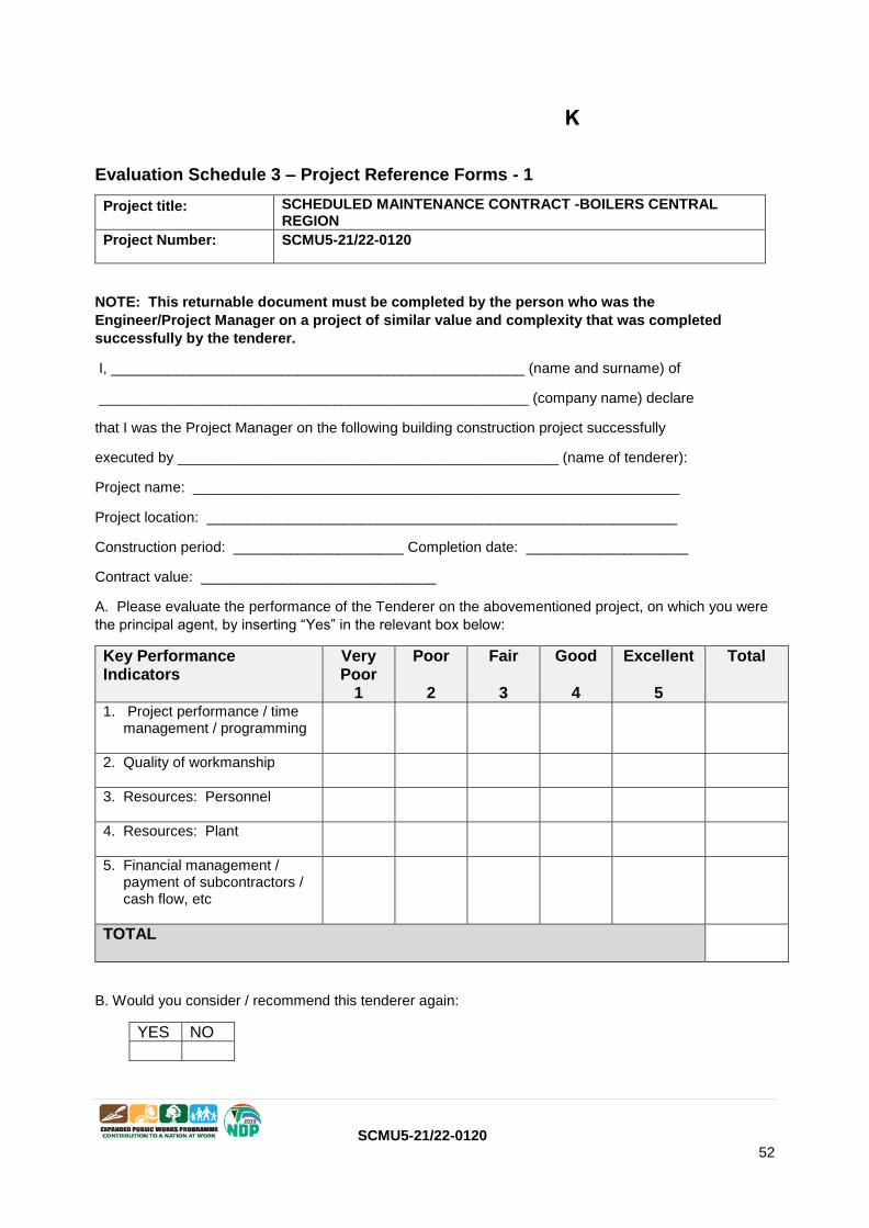
SCMU5-21/22-0120 52
Evaluation Schedule 3 – Project Reference Forms - 1
NOTE: This returnable document must be completed by the person who was the
Engineer/Project Manager on a project of similar value and complexity that was completed
successfully by the tenderer.
I, ___________________________________________________ (name and surname) of
_____________________________________________________ (company name) declare
that I was the Project Manager on the following building construction project successfully
executed by _______________________________________________ (name of tenderer):
Project name: ____________________________________________________________
Project location: __________________________________________________________
Construction period: _____________________ Completion date: ____________________
Contract value: _____________________________
A. Please evaluate the performance of the Tenderer on the abovementioned project, on which you were
the principal agent, by inserting “Yes” in the relevant box below:
Key Performance Indicators
Very Poor
1
Poor 2
Fair
3
Good 4
Excellent
5
Total
1. Project performance / time management / programming
2. Quality of workmanship
3. Resources: Personnel
4. Resources: Plant
5. Financial management / payment of subcontractors / cash flow, etc
TOTAL
B. Would you consider / recommend this tenderer again:
YES NO
Project title: SCHEDULED MAINTENANCE CONTRACT -BOILERS CENTRAL REGION
Project Number: SCMU5-21/22-0120
K
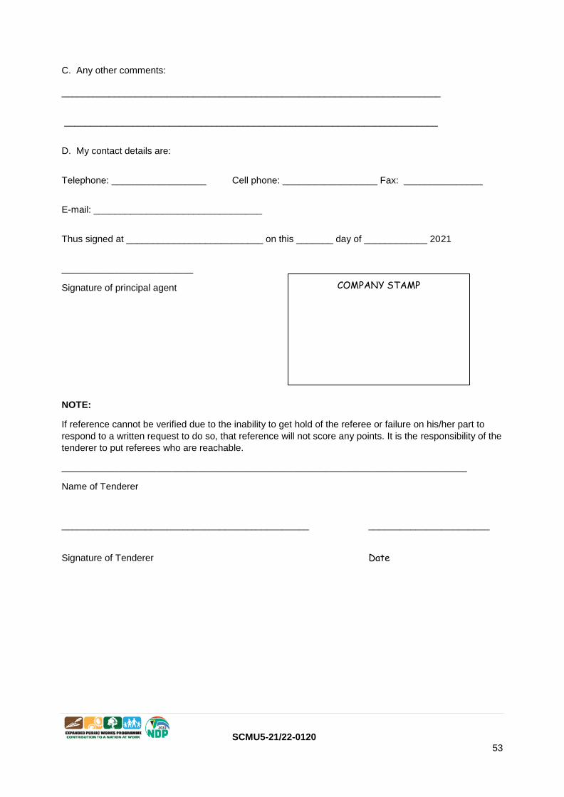
SCMU5-21/22-0120 53
C. Any other comments:
________________________________________________________________________
_______________________________________________________________________
D. My contact details are:
Telephone: __________________ Cell phone: __________________ Fax: _______________
E-mail: ________________________________
Thus signed at __________________________ on this _______ day of ____________ 2021
_________________________
Signature of principal agent
NOTE:
If reference cannot be verified due to the inability to get hold of the referee or failure on his/her part to
respond to a written request to do so, that reference will not score any points. It is the responsibility of the
tenderer to put referees who are reachable.
_____________________________________________________________________________
Name of Tenderer
_______________________________________________ _______________________
Signature of Tenderer Date
COMPANY STAMP
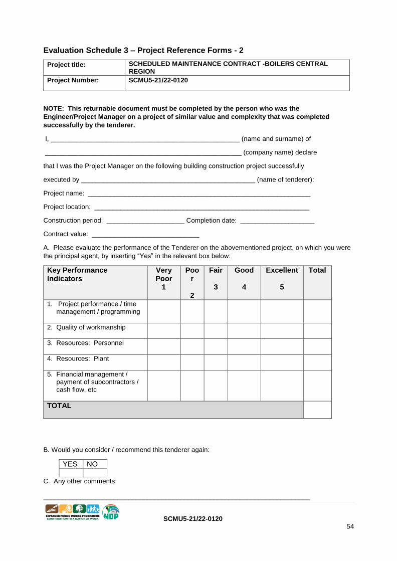
SCMU5-21/22-0120 54
Evaluation Schedule 3 – Project Reference Forms - 2
NOTE: This returnable document must be completed by the person who was the
Engineer/Project Manager on a project of similar value and complexity that was completed
successfully by the tenderer.
I, ___________________________________________________ (name and surname) of
_____________________________________________________ (company name) declare
that I was the Project Manager on the following building construction project successfully
executed by _______________________________________________ (name of tenderer):
Project name: ____________________________________________________________
Project location: __________________________________________________________
Construction period: _____________________ Completion date: ____________________
Contract value: _____________________________
A. Please evaluate the performance of the Tenderer on the abovementioned project, on which you were
the principal agent, by inserting “Yes” in the relevant box below:
Key Performance Indicators
Very Poor
1
Poor 2
Fair 3
Good 4
Excellent
5
Total
1. Project performance / time management / programming
2. Quality of workmanship
3. Resources: Personnel
4. Resources: Plant
5. Financial management / payment of subcontractors / cash flow, etc
TOTAL
B. Would you consider / recommend this tenderer again:
YES NO
C. Any other comments:
________________________________________________________________________
Project title: SCHEDULED MAINTENANCE CONTRACT -BOILERS CENTRAL REGION
Project Number: SCMU5-21/22-0120
SCMU5-21/22-0120 55
_______________________________________________________________________
D. My contact details are:
Telephone: __________________ Cell phone: __________________ Fax: _______________
E-mail: ________________________________
Thus signed at __________________________ on this _______ day of ____________ 2021
_________________________
Signature of principal agent
NOTE:
If reference cannot be verified due to the inability to get hold of the referee or failure on his/her part to
respond to a written request to do so, that reference will not score any points. It is the responsibility of the
tenderer to put referees who are reachable.
_____________________________________________________________________________
Name of Tenderer
_______________________________________________ _______________________
Signature of Tenderer Date
COMPANY STAMP

SCMU5-21/22-0120 56
Evaluation Schedule 3 – Project Reference Forms - 3
NOTE: This returnable document must be completed by the person who was the
Engineer/Project Manager on a project of similar value and complexity that was completed
successfully by the tenderer.
I, ___________________________________________________ (name and surname) of
_____________________________________________________ (company name) declare
that I was the Project Manager on the following building construction project successfully
executed by _______________________________________________ (name of tenderer):
Project name: ____________________________________________________________
Project location: __________________________________________________________
Construction period: _____________________ Completion date: ____________________
Contract value: _____________________________
A. Please evaluate the performance of the Tenderer on the abovementioned project, on which you were
the principal agent, by inserting “Yes” in the relevant box below:
Key Performance Indicators
Very Poor
1
Poor 2
Fair 3
Good 4
Excellent
5
Total
1. Project performance / time management / programming
2. Quality of workmanship
3. Resources: Personnel
4. Resources: Plant
5. Financial management / payment of subcontractors / cash flow, etc
TOTAL
B. Would you consider / recommend this tenderer again:
YES NO
C. Any other comments:
________________________________________________________________________
Project title: SCHEDULED MAINTENANCE CONTRACT -BOILERS CENTRAL REGION
Project Number: SCMU5-21/22-0120

SCMU5-21/22-0120 57
_______________________________________________________________________
D. My contact details are
Telephone: __________________ Cell phone: __________________ Fax: _______________
E-mail: ________________________________
Thus signed at __________________________ on this _______ day of ____________ 2021
_________________________
Signature of principal agent
NOTE:
If reference cannot be verified due to the inability to get hold of the referee or failure on his/her part to
respond to a written request to do so, that reference will not score any points. It is the responsibility of the
tenderer to put referees who are reachable.
_____________________________________________________________________________
Name of Tenderer
_______________________________________________ _______________________
Signature of Tenderer Date
COMPANY STAMP

SCMU5-21/22-0120 58
PART C1 AGREEMENTS AND CONTRACT DATA
C1.1 Form of Offer and Acceptance C1.2 Contract Data for CIDB Standard Professional Services Contract
C1.3 CIDB Adjudicator’s Agreement

SCMU5-21/22-0120 59
C1.1
FORM OF OFFER AND ACCEPTANCE
Project title SCHEDULED MAINTENANCE CONTRACT BOILERS CENTRAL REGION
SCMU number SCMU5-21/22-0120
OFFER The employer, identified in the acceptance signature block, has solicited offers to enter into a contract for the procurement of:
…………………………………………………………………………………………………….…………………. The tenderer, identified in the offer signature block, has examined the documents listed in the tender data and addenda thereto as listed in the returnable schedules, and by submitting this offer has accepted the conditions of tender.
By the representative of the tenderer, deemed to be duly authorized, signing this part of this form of offer and acceptance, the tenderer offers to perform all of the obligations and liabilities of the contractor under the contract including compliance with all its terms and conditions according to their true intent and meaning for an amount to be determined in accordance with the conditions of contract identified in the contract data. THE OFFERED TOTAL OF THE PRICES INCLUSIVE OF VALUE ADDED TAX IS ………………………………………..………………..………………………………………..……..Rand (in
words);
R ……………………………………………………………………………………..…..…….(in figures) (or
other suitable wording)
This offer may be accepted by the employer by signing the acceptance part of this form of offer and acceptance and returning one copy of this document to the tenderer before the end of the period of validity stated in the tender data, whereupon the tenderer becomes the party named as the contractor in the conditions of contract identified in the contract data.
Signature ……………………………….……………………………………………………………………………………… Name ……………………………………………………………………………………………………………………... Capacity ……………………………………………………………………………………………………………………... for the tenderer ……………………………………………………………………………………………………………………...
(Name and address of organization) Name and signature of witness ………………………………………..……….. Date ………………………………………………………….
ACCEPTANCE By signing this part of this form of offer and acceptance, the employer identified below accepts the tenderer’s offer. In consideration thereof, the employer shall pay the contractor the amount due in accordance with the conditions of contract identified in the contract data. Acceptance of the tenderer’s offer shall form an agreement between the employer and the tenderer upon the terms and conditions contained in this agreement and in the contract that is the subject of this agreement. The terms of the contract, are contained in:
Part C1 Agreements and contract data, (which includes this agreement) Part C2 Pricing data
Part C3 Scope of work. Part C4 Site information and drawings and documents or parts thereof, which may be incorporated by reference into the above listed Parts.
Deviations from and amendments to the documents listed in the tender data and any addenda thereto as listed in the returnable schedules as well as any changes to the terms of the offer agreed by the tenderer and the employer during this process of offer and acceptance, are contained in the schedule of deviations attached to and forming part of this form of offer and acceptance. No amendments to or

SCMU5-21/22-0120 60
deviations from said documents are valid unless contained in this schedule. The tenderer shall within 3 weeks after receiving a completed copy of this agreement, including the schedule of deviations (if any), contact the employer’s agent (whose details are given in the contract data) to arrange the delivery of any securities, bonds, guarantees, proof of insurance and any other documentation to be provided in terms of the conditions of contract identified in the contract data. Failure to fulfil any of these obligations in accordance with those terms shall constitute a repudiation of this agreement. Notwithstanding anything contained herein, this agreement comes into effect on the date when the tenderer receives one fully completed original copy of this document, including the schedule of deviations (if any). Unless the tenderer (now contractor) within five working days of the date of such receipt notifies the employer in writing of any reason why he cannot accept the contents of this
agreement, this agreement shall constitute a binding contract between the parties.1
Signature …………………………………………………………………………………………………………………… Name …………………………………………………………………………………………………….……………… Capacity …………………………………………………………………………………………………………………… for the Employer ……………………………………………………………………………………………………………………
(Name and address of organization) Name and signature of witness ………………………………………….. Date ………………….. Schedule of Deviations
1 Subject _______________________________________________________________ Details _______________________________________________________________ 2 Subject _______________________________________________________________ Details _______________________________________________________________ 3 Subject _______________________________________________________________ Details _______________________________________________________________ 4 Subject _______________________________________________________________ Details _______________________________________________________________ By the duly authorised representatives signing this agreement, the employer and the tenderer agree to and accept the foregoing schedule of deviations as the only deviations from and amendments to the documents listed in the tender data and addenda thereto as listed in the tender schedules, as well as any confirmation, clarification or changes to the terms of the offer agreed by the tenderer and the employer during this process of offer and acceptance. It is expressly agreed that no other matter whether in writing, oral communication or implied during the period between the issue of the tender/ quotation documents and the receipt by the tenderer of a completed signed copy of this Agreement shall have any meaning or effect in the contract between the parties arising from this agreement.
1As an alternative, the following wording may be used:
Notwithstanding anything contained herein, this agreement comes into effect two working days after the submission by the employer of one
fully completed original copy of this document including the schedule of deviations (if any), to a courier-to-
counter delivery / counter-to-counter delivery / door-to-counter delivery /door-to-door delivery /courier service (delete that
which is not applicable), provided that the employer notifies the tenderer of the tracking number within 24 hours of such submission. Unless
the tenderer (now contractor) within seven working days of the date of such submission notifies the
employer in writing of any reason why he cannot accept the contents of this agreement, this agreement shall constitute a binding contract
between the parties

61
SCMU5-21/22-0120
PART C1.2 CONTRACT DATA
Tender No : SCMU5-21/22-0120
Project title:
SCHEDULED MAINTENANCE CONTRACT BOILERS CENTRAL REGION
Tender No: SCMU5-21/22-0120
Part 1– Data provided by the Employer
Clause Statement Data
1. General
The conditions of contract are the core
clauses and the clauses for main
Option:
A
Priced contract with price list
dispute resolution Option W1 Dispute resolution procedure
and secondary Options
X1
Price adjustment for inflation
X13 Performance Bond
X17 Low service damages
X18 Limitation of liability
X19 Task Order
of the NEC3 Term Service Contract
(April 2013)
X20
Key Performance Indicators
10.1 The Employer is (name): Eastern Cape Department of Health
Address
Department of Public Works and Infrastructure 3rd Floor. Office 3-46 Independence Avenue Qhasana Building 5605
62
SCMU5-21/22-0120
Represented By:
Tel No.
Fax No.
TBA
10.1 The Service Manager is (name): Department of Public Works and Infrastructure
3rd Floor. Office 3-46
Independence Avenue
Qhasana Building
5605
Tel
The Service Manager is (name): TBA
11.2(2) The Affected Property is Various Health Facilities in the Eastern Cape Province as
per Service Information
11.2(13) The service is Scheduled and Re-Active Maintenance of– BOILERS
For a period of 24 months
11.2(14 The following matters will be included in
Risk register
N/A
11.2(15) The Service Information is in
The Contract Part 1: Service Information - Scope of
Works. Works Information and all documents and
drawings to which it makes reference.
12.2 The law of the contract is the law of the Republic of South Africa
13.1 The language of this contract is English
13.2 The period for reply is 7 days
2. The Contractor’s responsibility (If the optional statement for this section is not used, no data will be required for this section)
21.1 The Contractor submits a first Plan for 2 weeks of the Contract Date acceptance within
3. Time
30.1 The starting date is at the Site Handover Meeting Date
30.2 The service period is 24 Months, Extendable for an additional 12 months based
on performance
4. Testing and defects Special testing may be requested by the Service
Manager.

63
SCMU5-21/22-0120
5. Payment
50.1 The assessment interval is Monthly
51.1 The currency of this contract is the
South African Rand
51.2 The period with which payments are
made is
30 Days after submission of a valid TAX Invoice to the
Employer
51.4
The interest rate is
(i) zero percent above the publicly quoted prime rate of interest (calculated on a 365-day year) charged by from time to time by the South African Reserve Bank (as certified, in the event of any dispute, by any manager of such bank, whose appointment it shall not be necessary to prove) for amounts due in Rands
6. Compensation Events (if the optional statement for this section is not used,
no data will be required for this section
These are additional compensation N/A events
7. Use of Equipment Plant and Materials No data is required for this section of the conditions
of contract.
64
SCMU5-21/22-0120
8. Risks and Insurance
80.1 These are additional Employer's risks N/A
83.1 The Employer provides these insurances
from the Insurance Table
N/A
83.1 The Employer provides these additional
insurances
N/A
83.1 The minimum amount of cover for
insurance against loss and damage
caused by the Contractor to the
Employer’s property is
R 5 000 000.00
83.1 The insurance against loss of or damage
to the works, Plant and Materials is to
include cover for Plant and Materials
provided by the Employer to an amount of
R 5 000 000.00
83.1 The minimum amount of cover for
insurance in respect of loss of or damage
to property (except the Employer’s
property, Plant and Materials and
Equipment) and liability for bodily injury to
or death of a person (not an employee of
the Contractor) arising from or in
connection with the Contractor’s Providing
the Service for any one event is:
R 5 000 000.00
83.1 The Minimum limit of indemnity for
insurance in respect of death of or bodily
injury to employees of the Contractor
arising out of and in course of their
employment in connection with this
contract for any one event is:
As prescribed by the Compensation for
Occupational
Injuries and Diseases Act No. 130 of 1993 and the
Contractor’s common law liability for people falling
outside the scope of the Act with a limit of Indemnity
of not less that R 5 000 000.00
9. Termination No data is required for this section of the conditions of
contract.
10. Data for main Option Clauses
A Priced Contract with Price List Option A
20.5 The Contractor prepares forecasts of the final
total of the Prices for the whole of the
service at intervals of no longer than
4 Weeks

65
SCMU5-21/22-0120
11. Data for Option W1
W1.1
The Adjudicator is (Name)
Address
Tel. No,
Fax No.
The person selected from the ICE-SA Division (or its successor body) of the South African Institution of Civil Engineering Panel of Adjudicators by the party intending to refer a dispute to him. (See www.icesa.org.za)
W1.2(3) The Adjudicator nominating body is: The Chairman of ICE-SA a joint Division of the South
African Institution of Civil Engineering
W1.4(2) The Tribunal is: Arbitration
W1.4(5) The Arbitration Procedure is The latest edition of Rules for the Conduct of
Arbitrations published by the Association of Arbitrators
(South Africa) or its successor body.
The place where arbitration is to be held is South Africa
The person or organization who will choose an arbitrator
- If the Parties cannot agree a choice or
- If the procedure does not state
who selects an arbitrator, is
The Chairman for the time being or his nominee of the
Association of Arbitrators (South Africa) or its successor
body.
12. Data for Secondary Option Clauses
X1 Price Adjustment for Inflation
X1.1 The base date for indices is Tender Closing Date
The proportions used to calculate the Price Adjustment Factor are:
Note: Requirements for CPA/Price
inflation is that Prices must be Fixed and Firm for the First 12 months of the contract and only subject to escalation thereafter. A minimum of 10% of the contract price / prices is not adjustable throughout the life of the contract
Proportion Linked to Index
for
Index prepared
(Source)
by
Non-
Adjustable**
100%

66
SCMU5-21/22-0120
X13 Performance Bond
X13.1 The Contractor gives the Employer a The Tenderer must provide a Performance Bond in the performance bond
form of a Fixed Performance Guarantee by means of a
Bank Guarantee, or from an Insurer approved by the
Service Manager, in the amount of 2.5% of the Awarded Contract Value, once the Contract has been awarded to him. This Bond must be given to the Employer with in four (4) weeks of the Contract Date.
X17 Low Service Damages
X17.1
The service level table is in
As per Demerit Table in Contact Data – Annexure CD1
X18 Limitation of Liability
X18.1 The Contractor’s liability to the Employer for
indirect or consequential loss is limited to
R0.0 (zero Rand)
X18.2 For any one event, the Contractor’s liability to
the Employer for loss of or damage to the
Employer’s property is limited to
R2 500 000.00
X18.3 The Contractor’s liability for Defects due to
his design of an item of Equipment is limited
to
The greater of
• the total of the Prices at the Contract Date And
• R2 500 000
X18.4 The Contractor’s liability to the Employer for
all matters arising under or in connection with
this contract, other than the excluded
matters, is limited to
N/A
X18.5 The end of liability date is 3 Months after the end of the Service Period.
X19
Task Order
The Contractor submits a Task Order
programme to the Service Manager within
Authorization to commence with any Task will be done by Task Order. This Task Order will be issued to the Contractor by the Service Manager. Maintenance Turn- around times are stated in the Works Instructions under specification clause GM7.
X20
Key Performance Indicators
Key performance Indicators will be used to monitor Contractor performance on a monthly basis

67
SCMU5-21/22-0120
- Part Two – Data provided by the Contractor Clause Statement Data
10.1 The Contractor is (Name):
Address:
Tel No.
Fax No.
11.2(8) The Direct Fee Percentage is
_______________%
The Subcontracted Fee Percentage Is
_______________%
11.2(14) The following matters will be included
in the Risk Register
11.2(15) The Service Information for the
Contractor’s plan is in:
21.1 The plan identified in the Contract Data
is contained in:
24.1 The Key Persons are:
Name :
Job :
Responsibilities :
Qualifications :
Experience
Name :
Job :
Responsibilities :
Qualifications :
Experience
CV’s and further key person’s data are in
_____________
A Priced Contract with Price List
11.2(12) The price list is in

68
SCMU5-21/22-0120
11.2(19) The tendered total of the Prices is
X1 Price adjustment for inflation
X1.1
Proportion Linked to Index for Index prepared by (Source)
Non-Adjustable**
100%

69
SCMU5-21/22-0120
Annexure CD1 – Demerit Table and Penalty Calculation System
Project title: SCHEDULED MAINTENANCE CONTRACT– BOILERS –CENTRAL REGION
Bid No: SCMU5-21/22-0120
Attach document here

70
SCMU5-21/22-0120
ANNEXURE CD1: DEMERIT TABLE AND PENALTY CALCULATION SYSTEM
If the Contractor fails to remedy any sub-standard work within the time frame stipulated by the Service
Manager, the conditions as per GM 3.1 will apply.
The contractor will incur demerit points for specific measurable poor performance incidents which can lead
to the early termination of the Contract as described below.
DESCRIPTION DEMERIT POINT
Failure to submit the Functional Condition Assessment Report by the due date 1 point/ week that
the report is late
Exceeding the maximum allowable response and resolve time for a P1
Breakdown 3 points/ incident
Exceeding the maximum allowable response and resolve time for a P2
Breakdown 2 points/ incident
Exceeding the maximum allowable response and resolve time for a P3 or P4
Breakdown 1 point/ incident
Not meeting the Planned Maintenance Performance KPI 1 point/ incident
Not meeting the Rework Rate KPI 1 point/ incident
Not meeting the Contractor Contact ability KPI 1 point/ incident
The demerit points will accumulate and trigger the following actions:
ACCUMULATED
DEMERIT POINTS
ACTION
6
Service Manager to discuss Contractor’s performance deviation and agree on
improvement measures. If improvement measures are successful and the
Contractor has been consistently meeting the required KPI targets for the
following two months, the demerit points can be cancelled by the Service
Manager.

71
SCMU5-21/22-0120
12
Service Manager to issue notice that Contractor is in Breach of Contract and
that Contract Can be terminated if the Contractor does not improve his
performance in line with the agreed improvement measures.
15 Service Manager to Terminate Contract as per Clause 9 of the NEC3 Term
Service Contract.
Poor performance by the Contractor due to late payments by the Employer will not incur demerit points.
Financial penalties, as per the requirements of Secondary Options Clause X17, will be applied on the
effected payments at 1% penalty per demerit point by the Service Manager, in the month that the demerit
points are allocated to the Contractor.

72
SCMU5-21/22-0120
Annexure CD2 – Key Performance Indicator Listing
Project title: SCHEDULED MAINTENANCE CONTRACT – BOILERS CENTRAL REGION
Bid No: SCMU5-21/22-0120

73
SCMU5-21/22-0120
ANNEXURE CD2: KEY PERFORMANCE INDICATOR LISTING
The following Key Performance Indicators (KPI’s) will be applicable to this Contract and must be monthly
updated and reported on by the Service Manager:
KPI Name
KPI Equation
Frequency Target
Emergency Job Rate = Total Number of Emergency Jobs Done
X 100% Monthly <10% Total Number of Jobs Done
Planned
Maintenance
Performance
=
Total Number of Scheduled Planned Maintenance
Jobs Completed X 100% Monthly 100%
Total Number of Planned Maintenance Jobs
Scheduled
Cost Estimation
Accuracy =
Total Actual Cost of Work X 100% Monthly 100%
Total Estimated Cost Of Work
Response
Performance =
Number of Service Calls Completed within
Targeted Response Time X 100% Monthly 100%
Total Number of Service Calls
Rework Rate = Number of Jobs Requiring Rework
X 100% Monthly 0% Total Number of Jobs Done
SHEQ = Number of SHEQ Incidents Involving the Contractor
Monthly 0
Contractor Contact
ability =
Number of Times that Contractor was not
Contactable by the Call Cen tre Monthly 0
The Service Manager must also ensure that the following items are routinely inspected and reported on by
the Site Representative for each Health Facility:
1. Compliance with general maintenance requirements as specified in the Service Information.
2. Manner in which preventative and corrective maintenance is carried out.
3. Manner in which the Maintenance Control Plan is implemented and updated.

74
SCMU5-21/22-0120
4. Manner in which Task Orders received from the Service Manager is dealt with.
5. Manner in which records are kept as required by the Service Information as well as the Occupational
Health and Safety Act, Act No 85 of 1993 as amended.
6. Quality of services carried out for the month prior to the inspection.
Note: The aim of the above inspection is to determine that all the requirements of the specification have
been complied with. Should the Service Manager believe that one or more maintenance items
referred to above, have been neglected or totally ignored by the Contractor he may decide to
implement demerit points as penalty as per X17 for each type of non-compliance found during the
inspection.

75
SCMU5-21/22-0120
C1.3 CIDB ADJUDICATOR’S AGREEMENT
This agreement is made on the . . . . . . . . day of . . . . . . . . . . . . . . . between:. . . . . . . . . . . . . . . . . . . . . . . .
. . . . . . . . . . . . . . . . . . . . . . . . . . . (name of company / organization) of . . . . . . . . . . . . . . . . . . . . . . . . . . . . . .
. . . . . . . . . . . . . . . . . . . . . . . . . . . . . . . . . . . . . . . . . . . . . . . . . . . . . . . . . . . . . . . . . . . . . . . . . . . . . . . . . . . . . .
. . . . (address) and. . . . . . . . . . . . . . . . . . . . . . . . . . . . . . . . . . . . . . . . . . . . . . . . . . . (name of company /
organization) of . . . . . . . . . . . . . . . . . . . . . . . . . . . . . . . . . . . . . . . . . . . . . . . . . . . . . . . . . . . . . . . . . . . . . . . . .
. . . . . . . . . . . . . . . . . . . . . . . . . . . . . . . . . . . . . . . . . . . . . . . . . . . . . . . . . . . . . . (address) (the Parties) and. .
. . . . . . . . . . . . . . . . . . . . . . . . . . . . . . . . . . . . . . . . . . . . . . . . . (name) of . . . . . . . . . . . . . . . . . . . . . . . . . . . .
. . . . . . . . . . . . . . . . . . . . . . . . . . . . . . . . . . . . . . . . . . . . . . . . . . . . . . . . . . . . . . . . . . . . . . . . . . . . . . . . . . . . . .
. . . . . . . . . . . . . . . . . . . . . (address)
(the Adjudicator).
Disputes or differences may arise/have arisen* between the Parties under a Contract dated . . . . . . . .
and known as. . . . . . . . . . . . . . . . . . . . . . . . . . . . . . . . . . . . . . . . . . . . . . . . . . . . . . . . . . . . . . . . . . . . . .
and these disputes or differences shall be/have been* referred to adjudication in accordance with the CIDB Adjudication Procedure, (hereinafter called "the Procedure") and the Adjudicator may be or has been requested to act. * Delete as necessary IT IS NOW AGREED as follows: 1 The rights and obligations of the Adjudicator and the Parties shall be as set out in the Procedure. 2 The Adjudicator hereby accepts the appointment and agrees to conduct the adjudication in
accordance with the Procedure. 3 The Parties bind themselves jointly and severally to pay the Adjudicator's fees and expenses in
accordance with the Procedure as set out in the Contract Data. 4 The Parties and the Adjudicator shall at all times maintain the confidentiality of the adjudication and
shall endeavour to ensure that anyone acting on their behalf or through them will do likewise, save with the consent of the other Parties which consent shall not be unreasonably refused.
5 The Adjudicator shall inform the Parties if he intends to destroy the documents which have been sent to him in relation to the adjudication and he shall retain documents for a further period at the request of either Party.
SIGNED by: SIGNED by: SIGNED by:
Name: Name: Name:
Witness Witness: Witness:
Name: Name Name:
Address: Address: Address:

76
SCMU5-21/22-0120
Date: Date: Date:
Contract Data
1 The Adjudicator shall be paid at the hourly rate of R. . . . . . . . . . . . in respect of all time spent upon, or in connection with, the adjudication including time spent travelling.
2 The Adjudicator shall be reimbursed in respect of all disbursements properly made including, but not restricted to: (a) Printing, reproduction and purchase of documents, drawings, maps, records and
photographs. (b) Telegrams, telex, faxes, and telephone calls. (c) Postage and similar delivery charges. (d) Travelling, hotel expenses and other similar disbursements. (e) Room charges. (f) Charges for legal or technical advice obtained in accordance with the Procedure.
3 The Adjudicator shall be paid an appointment fee of R . . . . . . . . . . . . . This fee shall become payable in equal amounts by each Party within ….. days of the appointment of the Adjudicator, subject to an Invoice being provided. This fee will be deducted from the final statement of any sums which shall become payable under item 1 and/or item 2 of the Contract Data. If the final statement is less than the appointment fee the balance shall be refunded to the Parties.
4 The Adjudicator is/is not* currently registered for VAT.
5 Where the Adjudicator is registered for VAT it shall be charged additionally in accordance with the rates current at the date of invoice.
6 All payments, other than the appointment fee (item 3) shall become due 7 days after receipt of invoice, thereafter interest shall be payable at 5% per annum above the Reserve Bank base rate for every day the amount remains outstanding.
* Delete as necessary
77
SCMU5-21/22-0120
C1.4 OCCUPATIONAL HEALTH AND SAFETY SPECIFICATION
IMPLEMENTED BY THE DEPARTMENT OF PUBLIC WORKS
78
SCMU5-21/22-0120
TABLE OF CONTENT
1. Preamble .....................................................................................................................3
2. Scope of health & safety specification document…………………………………………………...5
3. Purpose ………………………………………………………………………………………5
4. Definitions……………………………………………………………………………………..6
5. Occupational health & safety management…………………………………………………..8
5.1 Structure and organization of OHS responsibilities..........................................................8
5.1.1 Overall supervision and responsibilities OHS…………………………………………………..8
5.1.2 Required appointment as per the construction regulation……………………………….10
5.2 Communication, participation & consultation………………………………………………...11
6. Interpretation………………………………………………………………………………….11
7. Responsibilities……………………………………………………………………………….12
7.1 Client...........................................................................................................................12
7.2 Principal contractor.......................................................................................................13
7.3 Contractor…………………………………………………………………………………….14
7.4 Responsibilities of Construction Health & Safety Agent (SACPCMP)……………………….15
8. Scope of work…………………………………………………………………………………16
9. Preparing Health & Safety Plan……………………………………………………………….16
10. Health & Safety File…………………………………………………………………………...19
11. OH&S Goals & Objective & Arrangements for Monitoring & Reviewing OH&S Performance..19
11.1 Identification of Hazards & development of Risk Assessment, Standard working
Procedures (SWP) & Method Statement...........................................................................19 11.1.1. Monthly audit by client and/or its agent……………………………………………………19
11.1.2 Health & Safety incident/accident reporting and investigation……………………………..19
12. Review...........................................................................................................................21
12.1 Site Rules & other Restrictions……………………………………………………………….22
12.1.1 Appointment of Health & Safety Reps……………………………………………………..23
12.1.2 Duties and functions of the Health & Safety Reps…………………………………………23
12.1.3 Establishment of Health & Safety Committee……………………………………………...23
12.1.4 Training & Awareness………………………………………………………………………2
13. Project Site Specific Requirements…………………………………………………………….25
14. Outlined Data References & information on Certain & Specific Obligatory Requirements to ensure compliance…………………………………………………………….26 15. Principal Contractor General duties...................................................................................30

79
SCMU5-21/22-0120
16. The Principal Contractor Specific Duties............................................................................31 17. The Principal Contractor Specific Responsibilities with regard to hazardous activities………..31
18. General Notes to the Principal Contractor……………………………………………………..32 19. House Keeping…………………………………………………………………………………33 20. Lockout System………………………………………………………………………………...36 21. Important Lists & Records to be kept.................................................................................36

80
SCMU5-21/22-0120
1. PREAMBLE
In terms of Construction Regulation 4(1)(a) of the Occupational Health and Safety Act, 1993 (Act 85 of
1993), and 5(1) construction regulation of 2014, the Department of Public Works, as the Client and/or its
Agent on its behalf, shall be responsible to prepare Health & Safety Specifications for any intended
construction project and provide any Principal Contractor who is making a bid or appointed to perform
construction work for the Client and/or its Agent on its behalf with the same.
The Client’s further duties are as described in The Act and the Regulations made there-under. The Principal
Contractor shall be responsible for the Health & Safety Policy for the site in terms of Section 7 of the Act
and in line with Construction Regulation 5 as well as the Health and Safety Plan for the project.
This ‘Health and Safety Specifications’ document is governed by the “Occupational Health and Safety Act,
1993 (Act No. 85 of 1993), hereinafter referred to as ‘The Act’. Notwithstanding this, cognizance should be
taken of the fact that no single Act or its set of Regulations can be read in isolation. Furthermore, although
the definition of Health and Safety Specifications stipulates ‘a documented specification of all health and
safety requirements pertaining to associated works on a construction site, so as to ensure the health and
safety of persons’, it is required that the entire scope of the Labour legislation, including the Basic
Conditions of Employment Act be considered as part of the legal compliance system. With reference to this
specification document this requirement is limited to all health, safety and environmental issues pertaining
to the site of the project as referred to here-in. Despite the foregoing it is reiterated that environmental
management shall receive due attention.
Due to the wide scope and definition of construction work, every construction activity and site will be
different, and circumstances and conditions may change even on a daily basis. Therefore, due caution is to
be taken by the Principal Contractor when drafting the Health and Safety Plan based on these Health and
Safety Specifications. Prior to drafting the Health and Safety Plan, and in consideration of the information
contained here-in, the contractor shall set up a Risk Assessment Program to identify and determine the
scope and details of any risk associated with any hazard at the construction site, in order to identify the
steps needed to be taken to remove, reduce or control such hazard. This Risk Assessment and the steps
identified will be the basis or point of departure for the Health and Safety Plan. The Health and Safety Plan
shall include documented ‘Methods of Statement’ (see definitions under Construction Regulations) detailing
the key activities to be performed in order to reduce as far as practicable, the hazards identified in the Risk
Assessment.
In this a high premium is to be placed on the health and safety of the most valuable assets of the
Department of Public Works. These are its personnel, the personnel of its Clients and the physical assets of
which it is the custodian and may also include the public as well. The responsibilities the Department and
relevant stakeholders have toward its employees and other people present in the facilities or on the sites

81
SCMU5-21/22-0120
are captured further in this specification document. These responsibilities stem from both moral, civil and a
variety of legal obligations. The Principal Contractor is to take due cognisance of the above statement.
Every effort has been made to ensure that this specification document is accurate and adequate in all
respects. Should it however, contain any errors or omissions they may not be considered as grounds for
claims under the contract for additional reimbursement or extension of time, or relieve the Principal
Contractor from his responsibilities and accountability in respect of the project to which this specification
document pertains. Any such inaccuracies, inconsistencies and/or inadequacies must immediately be
brought to the attention of the Agent and/or Client.
2. SCOPE OF HEALTH AND SAFETY SPECIFICATION DOCUMENT
These Specifications should be read in conjunction with the Act, the Construction Regulations and all other
Regulations and Safety Standards which were or will be promulgated under the Act or incorporated into the
Act and be in force or come into force during the effective duration of the project. The stipulations in this
specification, as well as those contained in all other documentation pertaining to the project, including
contract documentation and technical specifications shall not be interpreted, in any way whatsoever, to
countermand or nullify any stipulation of the Act, Regulations and Safety Standards which are promulgated
under, or incorporated into the Act.
This health and safety specification in respect of a construction work contract: a) provides the overarching framework within which the contractor is required to demonstrate
compliance with certain requirements for occupation health and safety established by the
Occupational Health and Safety Act of 1993 during construction;
b) establishes the manner in which the contractor is to manage the risk of health and safety incidents in
during the construction; and
c) establishes the manner in which the employer’s health and safety agent will interact with the
contractor.
Note 1 This specification establishes generic requirements to enable the employer and the contractor to satisfy aspects of the
Occupational Health and Safety Act, 1993 (Act No. 85 of 1993) and the Construction Regulations, 2014. The contractor is required
to develop, implement and maintain package specific health and safety plans. The employer is required to provide certain package
specific information to the contractor or a health and safety specification for the works to enable such plans to be formulated.
Accordingly, this generic specification on its own cannot ensure compliance with the requirements of the aforementioned Act (See
Annexure A). Note 2: The Construction Regulations, 2014, require an employer to stop any contractor from executing construction work which is not in accordance with the contractor’s health and safety plan for the site or which poses to be a threat to the health and safety of persons. Note 3: This specification establishes generic health and safety requirements. Site specific requirements for health and safety are stated in the scope of work associated with a contract (see Annexure A).

82
SCMU5-21/22-0120
Note 4: The South African Council for the Project and Construction Management Professions has established the following specified categories of
registration in terms of the Project and Construction Management Professions Act of 2000 (Act No. 48 of 2000):
a) a Construction Health and Safety Agent who may be appointed by an employer to act as his agent in terms of the Occupational Health and
Safety Act of 1993 and the Construction Regulations issued in terms of that Act; b) a Construction Health and Safety Manager who may be appointed by an employer to complement his professional team or by a contractor
to manage company or project health and safety performance and compliance in accordance with the Occupational Health and Safety Act
and Regulations; and a Construction Health and Safety Officers who may be appointed by an employer to mitigate the risk on a project or by a contractor to monitor and assist on-site health and safety performance and compliance in accordance with the Occupational Health and
Safety Act and Regulations and services.
3. PURPOSE
The Department is obligated to implement measures to ensure the health and safety of all people and
properties affected under its custodianship or contractual commitments, and is further obligated to monitor
that these measures are structured and applied according to the requirements of these Health and Safety
Specifications.
The purpose of this specification document is to provide the relevant Principal Contractor (and his /her
contractor) with any information other than the standard conditions pertaining to construction sites which
might affect the health and safety of persons at work and the health and safety of persons in connection
with the use of plant and machinery; and to protect persons other than persons at work against hazards to
health and safety arising out of or in connection with the activities of persons at work during the carrying out
of construction work for the Department of Public Works. The Principal Contractor (and his /her contractor)
is to be briefed on the significant health and safety aspects of the project and to be provided with
information and requirements on inter alia:
a) Safety considerations affecting the site of the project and its environment;
b) Health and safety aspects of the associated structures and equipment;
c) submissions on health and safety matters required from the Principal Contractor (and his /her
contractor); and
d) the Principal Contractor’s (and his /her contractor) health & safety plan.
To serve to ensure that the Principal Contractor (and his /her contractor) is fully aware of what is expected
from him/her with regard to the Occupational Health and Safety Act, 1993 (Act No. 85 of 1993) and the
Regulations made there-under including the applicable safety standards, and in particular in terms of
Section 6, 7 and 8 of the construction regulation (2014).

83
SCMU5-21/22-0120
To inform the Principal Contractor that the Occupational Health and Safety Act, 1993 (Act 85 of 1993) in its
entirety shall apply to the contract to which this specification document applies. The Construction
Regulations promulgated on 07 February 2014.
CREATING AND MAINTAINING A SAFE AND HEALTHY WORK ENVIRONMENT
General
The contractor shall with respect to the site and the construction work that are contemplated:
1. cause a preliminary hazard identification to be performed by a competent person before
commencing any physical construction activity;
2. evaluate the risks associated with the identified hazard to the health and safety of such employees
and the steps that need to be taken to comply with the Act; and
3. as far as is reasonably practicable, prevent the exposure of such employees to the hazards
concerned or, where prevention is not reasonably practicable, minimize such exposure.
The contractor shall ensure that:
all reasonably practicable steps are taken to prevent the uncontrolled collapse of any new or
existing structure or any part thereof, which may become unstable or is in a temporary state of
weakness or instability due to the carrying out of construction work; no structure or part of a
structure is loaded in a manner which would render it unsafe; and
account of information, if any, provided by the designer of the structure is taken into account in the
risk assessment.
Note: The information provided by the designer should outline known or anticipated dangers or hazards relating to the work and make available all information required for the safe execution of the work. It should provide as relevant, geotechnical information (or make reference to reports provided in the site information), the loading the structure is designed to withstand, the methods and sequence of construction. The contractor shall carry out regular inspections and audits to ensure that the work is being performed in accordance with the requirements of this specification.

84
SCMU5-21/22-0120
4. DEFINITIONS
The most important definitions in the Act and Regulations pertaining to this specification document
are hereby extracted.
Act: the Occupational Health and Safety Act, 1993 (Act No. 85 of 1993)
Accident – means unplanned occurrence that happens due to the unsafe condition and may cause injury to
a person, damage to the property, material, plant, equipment and the environment;
Agent – means any person who acts as a representative for a client. The word agent, in some instances,
may be used interchangeable with the Construction Health and Safety Agent, the distinguishing factor will
be on the role expected to be played by the agent mentioned. For example, all H&S related issues (audits,
inspections, and/or reports) are done by the Construction Health and Safety Agent, whilst the accountability
of overall project success or portions of the work is done by the Agent i.e. Principal Agent or Project
Manager or Engineer.
Client means Department of Public Works
Competent person means a person who-
(a) has in respect of the work or task to be performed the required knowledge, training and experience
and, where applicable, qualifications, specific for that work or task: Provided that where appropriate
qualifications and training are registered in terms of the provisions of the National Qualifications
Framework Act, 2000 (Act No.67 of 2000), those qualifications and that training must be regarded as
the required qualifications and training; and
(b) Is familiar with the OHS Act, Act 85 of 1993 and with the applicable regulations made under the Act;
Construction Health & Safety Agent (SACPCMP) – The person or entity appointed by the client through
the Agent and who has a full authority and obligation to act on the client’s behalf in terms of the construction
regulations. Pr.CHSA means a competent person who acts as a representative for a Client in terms of
regulation (5)5.
Contract Amount” Financial value of the contract at the time of the award of the contract, exclusive of all
allowance and any value added tax or sales tax which the law requires the employer to pay to the
contractor.
contractor: person or organization that contracts to provide the work covered by the contract
contract manager: person appointed by the employer to administer the contract on his behalf
competent person: any person who:
a) has in respect of the work or task to be performed the required knowledge, training and experience
and, where applicable, qualifications specific to that work or task; and

85
SCMU5-21/22-0120
b) is familiar with the Act and applicable regulations made in terms of the Act
Note: The Regulations stipulate that where appropriate qualifications and training are registered in terms of
the provisions of the National Qualification Framework Act of 2000.those qualifications and training must be
regarded as the required qualifications and training.
danger: anything which may cause injury or damage to persons or property
employer: person or organisation that enters into a contract with the contractor for the provision of the work
covered by the contract
employer’s health and safety agent: the person appointed as agent by the employer in terms of
Regulation 4(5) of the Construction regulations and named in the contract data as the being the employer’s
agent responsible for health and safety matters. This is a Construction Health & Safety Agent
(SACPCMP)” – The person or entity appointed by the client through the Agent and who has a full authority
and obligation to act on the client’s behalf in terms of the construction regulations.
"Construction Manager (Site Agent)" means a competent person responsible for the management of the
physical construction processes and the coordination, administration and management of resources on a
construction site;
Construction Site means a work place where construction work is being performed;
Construction Supervisor means a competent person responsible for supervising construction activities on
a construction site;
Construction Vehicle means a vehicle used as a means of conveyance for transporting persons or
material, or persons and material, on and off the construction site for the purposes of performing
construction work;
Construction work means any work in connection with –
a) The construction, erection, alteration, renovation, repair, demolition or dismantling of or addition to a
building or any similar structure; or
b) the construction, erection, maintenance, demolition or dismantling of any bridge, dam, canal, road,
railway, runway, sewer or water reticulation system; or the moving of earth, clearing of land, the
making of excavation, piling, or any similar civil engineering structure or type of work;
Construction Work Permit means a document issued in terms of regulation 3 of the Construction
Regulations 2014;
CR refers to the Construction Regulations 2014.
Demolition Work means a method to dismantle, wreck, break, pull down or knock down of a structure or
part thereof by way of manual labour, machinery, or the use of explosives;

86
SCMU5-21/22-0120
ergonomics: the application of scientific information concerning humans to the design of objects, systems
and the environment for human use in order to optimize human well-being and overall system performance.
Fall Protection Plan means a documented plan, which includes and provides for-
All risks relating to working from a fall risk position, considering the nature of work undertaken;
The procedures and methods to be applied in order to eliminate the risk of falling; and
A rescue plan and procedures;
H&S – health and safety
hazard: a source of or exposure to danger
hazard identification: the identification and documenting of existing or expected hazards to the health and
safety of persons, which are normally associated with the type of construction work being executed or to be
executed.
Health and Safety File – means a file, or other record in permanent form, containing the information
required a contemplated in the regulations;
health and safety plan: a documented plan which addresses hazards identified and includes safe work
procedures to mitigate, reduce or control the hazards identified.
health and safety specification: a site, activity or project specific document pertaining to all health and
safety requirements related to construction work which is included in the contractor’s contract with the
employer or an order issued in terms of framework agreement
healthy: free from illness or injury attributable to occupational causes
incident: an event or occurrence occurring at work or arising out of or in connection with the activities of
persons at work, or in connection with the use of plant or machinery, in which, or in consequence of which:
a) any person dies, becomes unconscious, suffers the loss of a limb or part of a limb or is otherwise
injured or becomes ill to such a degree that he is likely either to die or to suffer a permanent physical
defect or likely to be unable for a period of at least 14 days either to work or to continue with the
activity for which he was employed or is usually employed;
b) a major incident occurred; or
c) the health or safety of any person was endangered and where:
i) a dangerous substance was spilled;
ii) the uncontrolled release of any substance under pressure took place;
iii) machinery or any part thereof fractured or failed resulting in flying, falling or uncontrolled
moving objects; or machinery ran out of control
inspector: a person designated as such under section 28 the Act
major incident: an occurrence of catastrophic proportions, resulting from the use of plant or machinery, or
from activities at a workplace.

87
SCMU5-21/22-0120
Medical Certificate of Fitness means a certificate contemplated in regulation 7(8) of Construction
Regulations 2014;
Practical Completion Certificates- A certificates issued in terms of a contract by the employer, signifying
that the whole of the construction works have reached a state of readiness for occupation or use for the
purposes intended, although some minor work may be outstanding.
"Professional Engineer or Professional Certificated Engineer" means a person holding registration as
either a Professional Engineer or Professional Certificated Engineer in terms of the Engineering Profession
Act, 2000 (Act No. 46 of 2000);
reasonably practicable: practicable having regard to:
a) the severity and scope of the hazard or risk concerned;
b) the state of knowledge reasonably available concerning that hazard or risk and of any means of
removing or mitigating that hazard or risk;
c) the availability and suitability of means to remove or mitigate that hazard or risk; and
d) the cost of removing or mitigating that hazard or risk in relation to the benefits deriving therefrom;
risk – means the likelihood that harm will occur and the subsequent consequences.
“Risk assessment” – means a process to determine any risk associated with any hazard at a construction
site in order to identify the steps needed to be taken to mitigate, reduce or control such hazards.
safe: free from any hazard
Safety Officer – a person deemed competent by SACPCMP under the relevant category of registration.
scaffold: any temporary elevated platform and supporting structure used for providing access to and
supporting workmen or materials or both
structure:
a) any building, steel or reinforced concrete structure (not being a building), railway line or siding,
bridge, waterworks, reservoir, pipe or pipeline, cable, sewer, sewage works, fixed vessels, road,
drainage works, earthworks, dam, wall, mast, tower, tower crane, bulk mixing plant, pylon, surface
and underground tanks, earth retaining structure or any structure designed to preserve or alter any
natural feature, and any other similar structure;
b) any false work, scaffold or other structure designed or used to provide support or means of access
during construction work; or
c) any fixed plant in respect of construction work which includes installation, commissioning,
decommissioning or dismantling and where any construction work involves a risk of a person falling
substance: any solid, liquid, vapour, gas or aerosol, or combination thereof
suitable: capable of fulfilling or having fulfilled the intended function or fit for its intended purpose

88
SCMU5-21/22-0120
temporary works: any false work, formwork, support work, scaffold, shoring or other temporary structure
designed to provide support or means of access during construction
workplace: any premises or place where a person performs work in the course of his employment
5. OCCUPATIONAL HEALTH & SAFETY MANAGEMENT
5.1 Structure and Organization of OH&S Responsibilities
5.1.1. Overall Supervision and Responsibility for OH&S
a) The Client and/or its Agent on its behalf to ensure that the Principal Contractor, appointed in terms
of Construction Regulation 4(1)(c), implements and maintains the agreed and approved H&S Plan.
Failure on the part of the Client or Agent to comply with this requirement will not relieve the Principal
Contractor from any one or more of his/her duties under the Act and Regulations.
b) The Chief Executive Officer of the Principal Contractor in terms of Section 16 (1) of the Act to ensure
that the Employer (as defined in the Act) complies with the Act. The pro forma Legal Compliance
Audit may be used for this purpose by the Principal Contractor or his/her appointed contractor.
c) All OH&S Act (85 /1993), Section 16 (2) appointee/s as detailed in his/her/their respective
appointment forms to regularly, in writing, report to their principals on matters of health and safety
per routine and ad hoc inspections and on any deviations as soon as observed, regardless of whether
the observation was made during any routine or ad hoc inspection and to ensure that the reports are
made available to the principal Contractor to become part of site records (Health & Safety File).
d) The Construction Supervisor and Assistant Construction Supervisor/s appointed in terms of
Construction Regulation 6 to regularly, in writing, report to their principals on matters of health and
safety per routine and ad hoc inspections and on any deviations as soon as observed, regardless of
whether the observation was made during any routine or ad hoc inspection and to ensure that the
reports are made available to the principal Contractor to become part of site records (Health & Safety
File).
e) All Health and Safety Representatives (SHE-Reps) shall act and report as per Section 18 of the Act.
5.12 Required appointments as per the Construction Regulations: -
Item Regulation Appointment Responsible
Person
1. 3. Application Construction work permit Client
2. 5(1)(k) Principal contractor for each phase or project Client

89
SCMU5-21/22-0120
3. 5(6) Construction Health & Safety Agent Client
4. 7.(1)(c) Contractor Principal
Contractor
5. 7(3) Contractor Contractor
6. 8(1) Construction manager Contractor
7. 8(2) Assistance Construction manager Contractor
8. 6(1) Construction supervisor Contractor
9. 6(2) Construction supervisor sub-ordinates Contractor
10. 8(5) Construction Safety Officer Contractor
11. 8(8) Responsible employee
12. 9(1) Person to carry out risk assessment Contractor
13. 10(1) Fall protection planner Contractor
14. 12(1) Temporal work designer
15. 12(2) Supervisor of temporal work operation
16. 13(1) Excavation supervisor Contractor
17. 13(2)(k) Competent person in the use of explosive for excavations Contractor
18. 14(11) Explosives expert Contractor
19. 14(1) Supervisor demolition work Contractor
20. 14(2) Scaffold supervisor Contractor
21. 16(1) Suspended platform supervisor Contractor
22. 18(1)a Rope access Contractor
23. 19(8)(a) Material hoist inspector Contractor
24. 20(1) Bulk mixing plant supervisor Contractor
25. 21(2) Explosive actuated fastening device inspector Contractor
26. 21(2)(g) Explosive actuated fastening device cartridge, nails and studs:
issuer & collector
Contractor

90
SCMU5-21/22-0120
27. 23 (1) Operator : construction vehicle and mobile plant Contractor
28. 28 (a) Stacking and storage supervisor Contractor
29. 29 (h) Fire equipment inspector Contractor
5.2 Communication, Participation & Consultation
5.2.1 Occupational Health & Safety matters/issues shall be communicated between the Employer, the
Principal Contractor, the other Contractors, the Designer and other concerned parties shall be
through the H&S Committee or other means determined by the client.
5.2.2 In addition to the above, communication may be directly to the Client or his appointed Agent,
verbally or in writing, as and when the need arises.
5.2.3 Consultation with the workforce on OH&S matters will be through their Supervisors and H&S
Representatives (‘SHE – Reps’)
5.2.4 The Principal Contractor will be responsible for the dissemination of all relevant OH&S information
to the other Contractors e.g. design changes agreed with the Client and/or its Agent on its behalf
and the Designer, instructions by the Client and/or his/her agent, exchange of information between
Contractors, the reporting of hazardous/dangerous conditions/situations etc.
6. INTERPRETATION
a) The Act and its associated regulations shall have precedence in the interpretation of any ambiguity
or inconsistency between it and this specification.
b) Compliance with the requirements of this specification does not necessarily result in compliance with
the provisions of the Act.
c) The Occupational Health and Safety Act and all its Regulations, with the exception of the Construction
Regulations, distinguish between the roles, responsibilities and functions of employers and
employees respectively. It views consultants and contractors as employees of the “owner” of a
construction or operational project, the “owner” being regarded as the employer.

91
SCMU5-21/22-0120
d) The position taken by the Construction Regulations is that the “owner”, in terms of its instructions,
operates (has to operate) in the role of client as per relevant definition. The contractors working for
the “client” are seen to be in two categories, i.e. the Principal Contractor and Contractors.
e) The Principal Contractor has to take full responsibility for the health and safety on the site of the
relevant project / contract. This includes monitoring health and safety conditions and overseeing
administrative measures required by the Construction Regulations from all contractors on the project
site.
f) The words Principal Contractor and Contractor in this document are used interchangeable, unless
clearly expressed otherwise to mean something else e.g. when used to describe roles,
responsibilities, functions, acts or omissions of the sub-contractor(s).
7. RESPONSIBILITIES
7.1 Client
a) The Client or his appointed Agent on his behalf will appoint each Principal Contractor for this project
or phase/section of the project in writing for assuming the role of Principal Contractor as intended by
the Construction Regulations.
b) The Client or his appointed Agent on his behalf shall discuss and negotiate with the Principal
Contractor the contents of the health and safety plan of the both Principal Contractor and Contractor
for approval.
c) The Client or his appointed Agent on his behalf will take reasonable steps to ensure that the health
and safety plan of both the Principal Contractor and Contractor is implemented and maintained. The
steps taken will include periodic audits at intervals of at least once every month.
d) The Client or his appointed Agent on his behalf, will prevent the Principal Contractor and/or the
Contractor from commencing or continuing with construction work should the Principal Contractor
and/or the Contractor at any stage in the execution of the works be found to:
have failed to have complied with any of the administrative measures required by the
Construction Regulations in preparation for the construction project or any physical preparations
necessary in terms of the Act;
have failed to implement or maintain their health and safety plan;
have executed construction work which is not in accordance with their health and safety plan; or
act in any way which may pose a threat to the health and safety of any person(s) present on the
site of the works or in its vicinity, irrespective of him/them being employed or legitimately on the
site of the works or in its vicinity.

92
SCMU5-21/22-0120
7.2 Principal Contractor
a) The Principal Contractor shall accept the appointment under the terms and Conditions of Contract.
The Principal Contractor shall sign and agree to those terms and conditions and shall, before
commencing work, notify the Department of Labour of the intended construction. Annexure 2 of this
construction regulation contains a “Notification of Construction Work” form. The Principal Contractor
shall submit the notification in writing prior to commencement of work and inform the Client or his
Agent accordingly.
b) The Principal Contractor shall ensure that he is fully conversant with the requirements of this
Specification and all relevant health and safety legislation.
c) The Principal Contractor will in no manner or means be absolved from the responsibility to comply
with all applicable sections of the Act, the Construction Regulations or any Regulations proclaimed
under the Act or which may perceivable be applicable to this contract.
d) The Principal Contractor shall provide and demonstrate to the Client a suitable and sufficiently
documented health and safety plan based on this Specification, the Act and the Construction
Regulations, which shall be applied from the date of commencement of and for the duration of
execution of the works. This plan shall, as appendices, include the health and safety plans of all Sub-
contractors for which he has to take responsibility in terms of this contract.
e) The Principal Contractor shall provide proof of his registration and good standing with the
Compensation Fund or with a licensed compensation insurer prior to commencement with the works.
f) The Potential Principal Contractor shall, in submitting his tender, demonstrate that he has made
provision for the cost of compliance with the specified health and safety requirements, the Act and
Construction Regulations. (Note: This shall have to be contained in the conditions of tender upon
which a tenderer’s offer is based.)
g) The Principal Contractor shall consistently demonstrate his competence and the adequacy of his
resources to perform the duties imposed on the Principal Contractor in terms of this Specification,
the Act and the Construction Regulations.
h) The Principal Contractor shall ensure that a copy of his health and safety plan is available on site and
is presented upon request to the Client, an Inspector, Employee or Sub-contractor.
i) The Principal Contractor shall ensure that a health and safety file, which shall include all
documentation required in terms of the provisions of this Specification, the Act and the Construction
Regulations, is opened and kept on site and made available to the Client or Inspector upon request.
Upon completion of the works, the Principal Contractor shall hand over a consolidated health and
safety file to the Client.

93
SCMU5-21/22-0120
j) The Principal Contractor shall, throughout execution of the contract, ensure that all conditions
imposed on his Sub-contractors in terms of the Act and the Construction Regulations are complied
with as if they were the Principal Contractor.
k) The Principal Contractor shall from time to time evaluate the relevance of the Health and Safety Plan
and revise the same as required, following which revised plan shall be submitted to the Client and/or
his/her Agent for approval.
7.3 Contractor / sub-contractor
The contractor must demonstrate to the Principal Contractor that he has the necessary competencies and
resources to perform the construction work safely.
Acceptance by the Principal Contractor of the contract with Public Works shall constitute acknowledgement
that the Principal Contractor has familiarised him/herself with the contents of the OHSE Spec and that
he/she will comply with all its obligations in respect thereof.
Due to fact that this document is based on legislative requirements, the Client requires that all Contractors
comply with the requirements of this document and all other relevant legislative requirements not covered
by this document.
The Client or its duly appointed Construction H&S Agent reserves the right to stop any Principal Contractor
or Sub-Contractors from working whenever Safety, Health or Environmental requirements are being
violated as required by regulation 5(1)(q). Any resultant costs of such work stoppages will be for the
relevant Contractor’s account.
The requirements as specified by the Client in this document must not be deemed to be exhaustive and the
Client reserves the right to make changes as and when the Client deems fit to address issue of OHSE
Compliance.
The Client will not entertain any claim of any nature whatsoever which arises as a result of costs incurred or
delays being experienced due to the Contractor not complying with the requirements of this document
and/or any other applicable legislative requirements imposed on the Contractor.
The contractor may only subcontract work in terms of a written subcontract and shall only appoint a
subcontractor should he be reasonably satisfied that such a subcontractor has the necessary competencies
and resources to safely perform the work falling within the scope of the contract. Such a subcontract shall
require that the subcontractor:

94
SCMU5-21/22-0120
co-operate with the contractor as far as is necessary to enable both the contractor and sub-
contractor to comply with the provisions of the Act; and
as far as is reasonably practicable, promptly provide the contractor with any information which
might affect the health and safety of any person at work carrying out work or any person who
might be affected by the work of such a person at work or which might justify a review of the
health and safety plan.
The contractor shall provide any sub-contractor who is submitting a tender or appointed to perform a sub-
contract falling within the scope of the contract, with the relevant sections of this specification and the health
and safety specification.
The contractor shall discuss and negotiate with each subcontractor performing construction work the
subcontractor’s health and safety plan and approve that plan for implementation.
The contractor shall take reasonable steps as are necessary to ensure that:
potential contractors submitting tenders have made sufficient provision for health and safety
measures during the construction process;
each subcontractor is registered and in good standing with the compensation fund or with a
licensed compensation insurer prior to their performance of work on site;
all the subcontractor’s employees have a valid medical certificate of fitness specific to the
construction work which are to be performed which is issued by an occupational health and
safety practitioner;
all sub-contractors co-operate with each other to enable each of those sub-contractors to
comply with the requirements of the Act and associated regulations;
each subcontractor performing construction work has and maintains a health and safety file
containing the relevant information described in 4.2.5; and
each sub-contractor’s health and safety plan is implemented and maintained.
The contractor shall conduct periodic document verifications and audits for compliance with the approved
health and safety plan of each and every sub-contractor working on the site at intervals agreed upon with
such subcontractors, but at least once per month.
The contractor shall stop any subcontractor from executing construction work which is not in accordance
with the contractor’s or subcontractor’s health and safety plan for the site or which poses a threat to the
health and safety of persons.

95
SCMU5-21/22-0120
The contractor shall ensure that where changes to the works occur including design changes, sufficient
health and safety information and appropriate resources are made available to subcontractor to execute the
work safely.
The contractor shall ensure that:
every subcontractor is registered and in good standing with the compensation fund or with a
licensed compensation insurer prior to work commencing on site;
potential subcontractors submitting tenders have made provision for the cost of health and
safety measures during the construction process; and
every subcontractor has in place a documented health and safety plan prior to commencing
any work on site which falls within the scope of the contract.
The contractor shall receive, discuss and approve health and safety plans submitted by subcontractors.
The contractor shall ensure that all subcontractors are informed regarding any hazard as stipulated in the
risk assessment before any work commences, and thereafter at such times as may be determined in the
risk assessment.
The contractor shall reasonably satisfy himself that all employees of subcontractors are informed, instructed
and trained by a competent person regarding any hazard and the related work procedures before any work
commences, and thereafter at such times as may be determined in the risk assessment.
The contractor shall satisfy himself and ensure that all subcontractor employees deployed in the site are:
informed, instructed and trained by a competent person regarding any hazard and the related work
procedures before any work commences, and thereafter at such times as may be determined in the
risk assessment; and
issued with proof of health and safety induction training issued by a competent person and carry
proof such induction when working on site.
The contractor shall undertake a risk assessment together with subcontractors whenever subcontractors
are working in close proximity to other subcontractors particularly
activities involve excavations, the moving of earth, the movement of heavy machinery
and working at heights
7.4 Construction supervisors
The construction manager shall in writing appoint construction supervisors responsible for construction activities and ensuring occupational health and safety compliance on the construction site.

96
SCMU5-21/22-0120
A contractor shall after considering the size of the project and if considered necessary, appoint in writing one or more competent employees for different sections of the work to assist the construction supervisor.
7.5 Competent persons The contractor shall appoint in writing competent persons to supervise or inspect, as relevant, any of the following:
formwork and support work operations;
excavation work;
demolition work;
scaffolding work operations;
suspended platform work operations;
material hoists;
bulk mixing plants;
temporary electrical installations;
the stacking and storage of articles on the site; and
fire equipment.
The contractor shall appoint in writing competent persons to:
induct employees in health and safety; and
prepare and update as necessary a fall protection plan and to provide the construction manager
with a copy of the latest version of such plan.
6. Appointment of a Fulltime/ Part time Safety Officer
The Principal Contractors will have to appoint a competent Construction H&S Officer as per the following
criteria;
i. Number of employees onsite between 30 but below 50 – Part Time Safety Officer shall be appointed
and will be onsite at least 2 days a week.
ii. Number of employees above 50 – Fulltime Safety Officer should be appointed.
iii. Should the project require a Construction Work Permit – a Fulltime Safety Officer should be
appointed.
Further to the above criteria, should the Client or its Representative having considered the risks present and
lack of compliance to the Occupational Health and Safety Act, Act 85 of 1993 and its applicable Regulations
the Client or its Representative may issue an instruction that a Part/ Full Time Construction Health and

97
SCMU5-21/22-0120
Safety Officer must be appointed, such a requirement will have to be met. Taking the Risk associated with
this project into consideration it is deemed that a full time Safety Officer needs to be appointed and be
present on site at all times.
7.6 Responsibilities towards employees and visitors
1. The contractor shall as far as is reasonably practicable, cause every employee to be made
conversant with the hazards to his health and safety attached to any work which he has to perform,
any article or substance which he has to produce, process, use, handle, store or transport and any
plant or machinery which he is required or permitted to use, as well as with the precautionary
measures which should be taken and observed with respect to those hazards or safe work
procedures.
2. The contractor shall ensure that all employees under his or her control and the employees of his
subcontractors who are performing construction work are:
informed, instructed and trained by a competent person regarding any hazard and the related work
procedures before any work commences, and thereafter at such times as may be determined in the
risk assessment; and
issued with proof of health and safety induction training issued by a competent person and carry
proof of such induction when working on site.
3. The contractor shall cause a record of training to be kept which indicates the training dates, the
names, identity numbers and job description of all those who attended such training and the name,
identity number and competence of the person who provided the training.
4. The contractor shall not allow or permit any employee to enter the site, unless such person has
undergone health and safety induction training pertaining to the hazards prevalent on the site at the
time of entry.
5. The contractor shall ensure that each visitor to a construction site, save where such visitor only
visits the site office and is not in direct contact with the construction work activities:
a. undergoes health and safety instruction pertaining to the hazards prevalent on the site; an
b. is provided with the necessary personal protective equipment.
6. The contractor shall provide suitable on-site signage to alert workers and visitors to health and
safety requirements. Such signage shall include but not be limited to:
a. unauthorized entrance prohibited;

98
SCMU5-21/22-0120
b. signage to indicate what personal protective equipment is to be worn; and
c. activity related signs.
7. The contractor shall not permit any person who is or who appears to be under the influence of
intoxicating liquor or drugs, to enter or remain at a workplace.
7.8 Design of temporary work
The contractor shall:
a) provide the health and safety agent with the names and contract particulars of the designers involved
in the design of temporary works;
b) issue the designers with a copy of the health and safety specification as well as any pertinent
information contained in the contract; and
c) provide the health and safety agent with certificates issued by the designer of the temporary works that
such works are fit for purpose before such works are used in support construction activities
7.9 Notification of intention to commence construction work
i. The contractor shall on sites where no construction work permit has been issued by the Provincial
Director of the Department of Labour notify such director in writing using a form similar to that
contained in Annexure 2 of the Construction Regulations issued in terms of the Act before
construction work commences and retain proof of such notification in the health and safety file
where the work includes:
a. excavation work;
b. working at height where there is a risk of falling;
c. the demolition of a structure;
d. the use of explosives; or
e. a single storey dwelling for a client who is going to reside in such dwelling upon completion
ii. The contractor shall ensure that no work commences on an electrical installation which requires a
new supply or an increase in electricity supply before the person who supplies or contracts or
agrees to supply electricity to that electrical installation has been notified of such work.
iii. The contractor shall ensure that no asbestos.
9. PREPARING A HEALTH & SAFETY PLAN
(a) The level of detail required for a H&S plan will depend on how complex the workplace is (in
particular, the number of contractors at the workplace at any one time) and the risks involved in the

99
SCMU5-21/22-0120
work. The plan must be easily accessible in a construction site and it must be clearly understood by
management, supervisors & workers on construction site.
(b) The plan must be implemented, maintained and kept up to date during the construction of the
project.
(c) The principal contractor should prepare a H&S plan that includes
project information;
client requirements for H&S management on the project;
Environmental restrictions and existing on-site risks arrangements, imposed
by others or developed by the principal contractor, to control significant site
H&S risks; H&S file & project H&S review.
(d) The H&S plan should include the following information:
details of the client, that is the person commissioning the construction work, for example their
name, representative and contact details;
details of the principal contractor;
details of the construction project, for example address of the workplace, anticipated start and
end date and a brief description of the type of construction work that the H&S plan will cover;
details on how subcontractors will be managed and monitored, including how the principal
contractor intends to implement and ensure compliance with the H&S plan such as checking
on the performance of subcontractors and how non-compliance will be handled; and
details on how the risks associated with falls, falling objects, moving plant, electrical work and
all high risk construction work that will take place on a construction project will be managed.
(e) The H&S plan should also include information on:
the provision and maintenance of a hazardous chemicals register, safety data sheets and
hazardous chemicals storage;
the safe use and storage of plant;
obtaining and providing essential services information – electrical, gas, telecom, water and
similar services;
workplace security and public safety; and
ensuring workers have appropriate licences and training to undertake the construction work.

100
SCMU5-21/22-0120
(f) The H&S plan must contain:
a general description of the type of work activities involved in the project and not just a
description of the facility to be constructed;
the project program or schedule details, including start and finish dates, showing principal
activities;
details of client, design team, principal contractor, subcontractors, and major suppliers; and
extent and location of relevant existing records, surveys, site investigation and geotechnical
reports, ‘as-built’ plans, H&S files.
10. HEALTH AND SAFETY FILE
a) The H&S file is a document prepared by the principal contractor containing important project H&S
information for use by the owner of the completed structure after construction has been completed.
b) The principal contractor is responsible for producing an H&S file. It contains important project H&S
information for use by the owner of the completed structure after construction has been completed.
It is essential that the process of compiling the file commences as early as possible to ensure
sufficient time to gather the required information.
c) The Principal Contractor must, in terms of Construction Regulation 7(7), keep a Health & Safety File
on site at all times that must include all documentation required in terms of the Act and Regulations
and must also include a list of all Contractors on site that are accountable to the Principal Contractor
and the agreements between the parties and details of work being done. A more detailed list of
documents and other legal requirements that must be kept in the Health & Safety File.
d) The contractor must ensure that the client’s format and layout of the H&S file is adhered to. The
contractor must identify the responsible person that will prepare the H&S file and who will be
responsible for the drafting of as-built drawings. The contractor must establish procedures:
e) The Health and Safety File will remain the property of the Client and/or its Agent on its behalf
throughout the period of the project and shall be consolidated and handed over to the Client and/or
its Agent on its behalf at the time of completion of the project.
f) The contractor shall establish and maintain on site a health and safety file which contains copies, as
relevant of:
the following documents which shall be placed in the file prior to commencing with physical construction
activities:
copy of the contraction work permit issued in terms of the Construction Regulations 2014;

101
SCMU5-21/22-0120
the contractor’s health and safety policy, signed by the chief executive officer, which outlines
the contractor’s objectives and how they will be achieved and implemented by the contractor;
copies of all risk assessments that were conducted.
the notification made to the Provincial Director of Labour, and if relevant, the notification of the
person who supplies or contracts or agrees to supply electricity to that electrical installation;
the letters of appointment, as relevant, together with a brief curriculum vita (CV) of:
— the construction manager and any assistant construction managers;
— the construction health and safety manager
— the construction health and safety officer
— the risk assessor who is tasked to perform the risk assessments; and
— the registered person responsible for the electrical installation covered by the Electrical
Installations Regulations;
— the authorised persons responsible for gas appliances, gas system gas reticulation
system covered by the Pressure Equipment Regulations;
g) a copy of the certificate of registration of the registered person responsible for the electrical
installation covered by the Electrical Installations Regulations;
h) the approval of the design of the part of an electrical installation which has a voltage in excess of 1
kV by a person deemed competent in terms of the Electrical Installations Regulations;
i) proof of registration of the electrical contractor who undertakes the electrical installation in terms of
the Electrical Installations Regulations;
j) the preliminary hazard identification undertaken by a competent person;
k) the organogram which outlines the roles of the construction supervisor’s assistants and safety
officers; and
l) the contractor’s health and safety plan;
m) the emergency procedures;
n) the procedure for the issuing and replacement of lost, stolen, worn or damaged personal protective
clothing and equipment; and
o) proof that the contractor and all the subcontractors are registered and in good standing with the
compensation fund or with a licensed compensation insurer relevant to the type of work performed;
p) the following documents, as relevant, which shall be placed in the file after construction activities
have commenced;
q) the letters of appointments, if relevant, together with a brief curriculum vita (CV) of:
— persons who are required to assist the construction supervisor;
— construction supervisor for the site in respect of construction work covered by the
Construction Regulations;

102
SCMU5-21/22-0120
— competent persons;
— assistants of construction supervisor; and
— designers of temporary works;
r) any revisions to the organogram which outlines the roles of the construction supervisor’s
assistants and safety officers;
s) each and every subcontract agreement and each and every subcontractor’s approved health and
safety plan;
t) proof that every subcontractor is registered and in good standing with the compensation fund or
with a licensed compensation insurer relevant to the type of work performed;
u) proof of all subcontractor’s induction training whenever it is conducted;
v) copies of the minutes of the contractor’s subcontractor’s health and safety meetings;
w) copies of each of the contractor’s subcontractors’ health and safety policy, signed by the chief
executive officer, which outlines the contractor’s objectives and how they will be achieved and
implemented by the contractor;
x) the health and safety plans of all the contractor’s subcontractors who are required to provide such
plans;
y) copies of the fall protection plan and each revision thereof;
z) a comprehensive and updated list of all the subcontractors employed on site by the contractor,
indicating the type of work being performed by such sub-contractors;
aa) the outcomes of the monthly audits for compliance with the approved health and safety plan of each
and every sub-contractor working on the site;
bb) any report made to an inspector by the health and safety committee;
cc) the minutes of all health and safety meetings and any recommendations made to the contractor by
the health and safety committee;
dd) the findings of all audit reports made regarding the implementation of the contractor’s or a
subcontractor’s health and safety plan;
ee) the inputs of the safety officer, if any, into the health and safety plan;
ff) details of induction training conducted whenever it is conducted including the list of attendees;
gg) proof of the following where suspended platforms are used:
— a certificate of system design issued by a professional engineer, professional certificated
engineer or a professional engineering technologist;
— proof of competency of erectors, operators and inspectors;
— proof of compliance of operational design calculations with requirements of the system
design certificate;
— proof of performance test results;

103
SCMU5-21/22-0120
— sketches indicating the completed system with the operational loading capacity of the
platform;
— procedures for and records of inspections having been carried out;
— procedures for and records of maintenance work having been carried out;
— proof that the prescribed documentation has been forwarded to the provincial director;
hh) letters of appointments for competent persons to supervise the activities which law requires to be
so supervised;
ii) a copy of risk assessments made by competent persons;
jj) records of the register of inspections made by a competent person immediately before and
during the placement of concrete or any other load on formwork;
kk) the names of the first aiders on site and copies of the first aid certificates of competency;
ll) the names of the persons the persons who are in possession of valid certificate of competency
in first aid and copies of such certificates;
mm) medical certificates of fitness for the contractor’s and subcontractors’ employees specific to the
construction work to be performed and issued by an occupational health and safety practitioner:
a. details of all incidents together with the Contractor’s investigative report on such incident;
b. the record of inspections carried out by the designers of structures to ensure compliance with
designs; and
nn) any other documentation required in terms of regulations issued in terms of the Act including a
record of all drawings, designs, materials used and other similar information concerning the
completed structure;
oo) The health and safety file shall be made available for inspection by any inspector, subcontractor,
the contract manager, the employer’s health and safety agent or employee of the contractor upon
the request of such persons.
pp) The health and safety file shall be updated to ensure that its contents always reflect the latest
available information.
qq) The contractor shall hand over a copy of the health and safety file to the employer’s health and
safety agent upon completion of the contract and if relevant, a certificate of compliance
accompanied by a test report for the electrical installation in accordance with the provisions of the
Electrical Installation Regulations.

104
SCMU5-21/22-0120
11.1 IDENTIFICATION OF HAZARDS AND DEVELOPMENT OF RISK ASSESSMENTS, STANDARD
WORKING PROCEDURES (SWP) AND METHOD STATEMENTS.
The Principal Contractor is required to develop Risk Assessments, Standard Working Procedures
(SWP) and Method Statements for each activity executed in the contract or project.
The identification of hazards is over and above the hazards identification programme and those
hazards identified during the drafting of the Health and Safety Plan.
11.1.1 Monthly Audit by Client and/or its H&S Agent.
The Client and/or its H&S Agent on its behalf will be conducting Periodic Audits at times agreed
with the Principal Contractor Audit to comply with Construction Regulation 4(1)(d) to ensure that the
principal Contractor has implemented, is adhering to and is maintaining the agreed and approved
OH&S Plan.
a) A representative of the Principal Contractor and the relevant Health and Safety
Representative(s) (SHE-Reps) must accompany the Client and/or its Agent on its behalf on
all Audits and Inspections and may conduct their own audit/inspection at the same time. Each
party will, however, take responsibility for the results of his/her own audit/inspection results.
The Client and/or its Agent on its behalf may require to be handed a copy of the minutes of
the previous Health and Safety Committee meeting reflecting possible recommendations
made by that committee to the Employer for reference purposes.
11.1.2 Health & Safety incident/accident reporting & investigations
a) The Principal Contractor shall report all incidents where an employee is injured on duty to the extent
that he/she:
i. dies
ii. becomes unconscious
iii. loses a limb or part of a limb
iv. is injured or becomes ill to such a degree that he/she is likely either to die or to suffer a
permanent physical defect or likely to be unable for a period of at least 14 days either to work
or continue with the activity for which he/she was usually employed
OR where:
a major incident occurred
i. the health or safety of any person was endangered
ii. where a dangerous substance was spilled
iii. the uncontrolled release of any substance under pressure took place

105
SCMU5-21/22-0120
iv. machinery or any part of machinery fractured or failed resulting in flying, falling or
uncontrolled moving objects
v. Machinery ran out of control, to the Provincial Director of the Department of Labour within
seven days and at the same time to the Client and/or its Agent on its behalf.
b) The Principal Contractor is required to provide the Client and/or its Agent on its behalf with copies of
all statutory reports required in terms of the Act and the Regulations.
c) The Principal Contractor is required to provide the Client and/or its Agent on its behalf with a monthly
“SHE Risk Management Report”.
d) The Principal Contractor is required to provide a.s.a.p. the Client and/or its Agent on its behalf with
copies of all internal and external accident/incident investigation reports.
The Principal Contractor is responsible to oversee the investigation of all accidents/incidents where
employees and non-employees were injured to the extent that he/she/they had to receive first aid or
be referred for medical treatment by a doctor, hospital or clinic. (General Administrative Regulation
9)
e) The results of the investigation to be entered into the Accident/Incident Register listed above.
(General Administrative Regulation 9)
f) The Principal Contractor is responsible for the investigation of all non-injury incidents as described
in Section 24 (1) (b) & (c) of the Act and keeping a record of the results of such investigations
including the steps taken to prevent similar incidents in future.
g) The Principal Contractor is responsible for the investigation of all accidents relating to the
construction site and keeping a record of the results of such investigations including the steps taken
to prevent similar accidents in future.
h) Notwithstanding the requirements of Section 24 of the Act, ALL incidents shall be investigated and
reported on in writing, irrespective of whether such incident gave rise to injury or damage.
Determine the underlying H&S deficiencies and other contributory factors
Identification of corrective/preventative actions and continual improvement
Communicating the outcome/results and documenting the events of the investigation.
Reporting of Near-Misses

106
SCMU5-21/22-0120
Department of Public Works views the reporting of near misses as a critical component in creating
a positive health and safety awareness culture on site.
Department of Public Works retains the right to enforce the reporting of near misses within 24
hours of occurrence.
12. Review
The Principal Contractor is to review the Hazard Identification, Risk Assessments and Standard
Work Processes at each Production Planning and Progress Report meeting as the construction
work develops and progresses and each time changes are made to the designs, plans and
construction methods and processes.
The Principal Contractor must provide the Client and/or its Agent on its behalf, other Contractors
and all other concerned parties with copies of any changes, alterations or amendments as
contemplated in the above paragraph.
12.1 Site Rules and other Restrictions
a) Site OH&S Rules
The Principal Contractor must develop a set of site-specific OH&S rules that will be applied to regulate
the Health and Safety Plan and associated aspects of the construction. When required for a site by law,
visitors and non-employees upon entering the site shall be issued with the proper Personal Protective
Equipment (PPE) as and when necessary.
b) Security Arrangements
The Principal Contractor must establish site access rules and implement and maintain these throughout
the construction period. Access control must include the rule that non-employees shall at all times be
provided with fulltime supervision while on site. The Principal Contractor must develop a set of Security
rules and procedures and maintain these throughout the construction period.
If not already tasked to the H&S Officer appointed in terms of Construction Regulation, the Principal
Contractor must appoint a competent person who must develop contingency plans for any emergency
that may arise on site as indicated by the risk assessments.
12.1.1 Appointment of Health & Safety Representatives
a) H&S Representatives (‘SHE – Reps’)
Where the Principal Contractor employs more than 20 persons (including the employees of other
Contractors (sub-contractors) he has to appoint one H&S Representatives for every 50 employees or
part thereof. (Section 17 of the Act and General Administrative Regulation 6. & 7.)

107
SCMU5-21/22-0120
H&S Representatives must be appointed in writing and the designation shall be in accordance with the
Collective Agreement as concluded between the parties as is required in terms of General
Administration Regulation 6.
12.1.2 Duties and Functions of the H&S Representatives
The contractor shall appoint in writing one health and safety representative for every 50 employees working
on the site, whenever there are more than 20 employees on the site, to:
conduct at least a weekly inspection of their respective areas of responsibility using a checklist
developed by a Principal Contractor.
review the effectiveness of health and safety measures;
identify potential hazards and potential major incidents;
in collaboration with his employer, examine the causes of incidents;
investigate complaints by any employee of the contractor relating to that employee's health or
safety on the site;
make representations to the contractor on matters arising from a), b), c) or d) or on general
matters affecting the health or safety of the employees at the workplace;
inspect the site with a view to, the health and safety of employees, at regular intervals;
participate in consultations with inspectors at the workplace and accompany inspectors on
inspections of the workplace; and
participate in any internal health or safety audit.
The report must be consolidated and submitted to the Health & Safety Committee.
H&S Representatives must form part of the incident/accident investigating team.
The contractor shall provide the health and safety representatives with the necessary assistance, facilities
and training to carry out the functions established above.
12.1.3 Establishment of H&S Committee(s)
The Principal Contractor must establish H&S Committees consisting of designated H&S
Representatives together with a number of Employers Representatives appointed as per Section
19(3) that are not allowed to exceed the number of H&S Representatives on the committee.
The persons nominated by the employer on a H&S Committee must be designated in writing for
such period as may be determined by him. The H&S Committee shall co-opt advisory (temporary)
members and determine the procedures of the meetings including the chairmanship.
The H&S Committee must meet minimum monthly and consider, at least, an agreed Agenda for
the first meeting. Thereafter the H&S Committee shall determine its own procedures.

108
SCMU5-21/22-0120
12.1.4 Training & Awareness
The contents and syllabi of all training required by the Act and Regulations including any other related or
relevant training as required must be included in the Principal Contractor’s Health and Safety Plan and
Health and Safety File.
a) Training & Induction
All employees performing work or task on site that potentially impact on H&S must be competent &
have the necessary appropriate education, training & experience.
All the training must be closely aligned with the risk profile of the project; procedures must be put in
place to ensure that all workers are aware of the consequences of their work activities & benefits of
improved H&S performance.
All employees of the Principal and other Contractors must be in possession of proof of General
Induction training
b) Site Specific Induction Training
All employees of the Principal and other Contractors must be in possession of Site Specific
Occupational Health and Safety Induction or other qualifying training.
c) Other Training
All operators, drivers and users of construction vehicles, mobile plant and other equipment must be in
possession of valid proof of training.
d) Copy of the Act
The contractor shall ensure that a copy of the Act and relevant regulations is available on site for
inspection by any person engaged in any activity on the site.
13. PROJECT/SITE SPECIFIC REQUIREMENTS
The following is a list of specific activities and considerations that have been identified for the project and
site and for which Risk Assessments, Standard Working Procedures (SWP), management and control
measures and Method Statements (where necessary) have to be developed by the Principal Contractor:
a) Site establishment
b) Dealing with existing structures
c) Location of existing services
d) Boundary & Access control/Public liability exposures
e) Protection against heat exhaustion, dehydration, wet & cold conditions

109
SCMU5-21/22-0120
f) Dealing with HIV & aids other related diseases
g) Use of portable electrical & explosive tools
h) Any Excavation work
i) Any welding work
j) Loading & offloading of trucks
k) Driving & operations of Construction vehicles & mobile plant
l) Temporal works and
m) Construction work as defined in the construction regulation 2014

110
SCMU5-21/22-0120
14. OUTLINED DATA, REFERENCES AND INFORMATION ON CERTAIN AND/OR SPECIFIC OBLIGATORY REQUIREMENTS TO ENSURE COMPLIANCE Administrative & Legal Requirements
(a) OHS Act Section/
(b) Regulation
c) Subject (1) Requirements
Construction. Regulation Notice of carrying out Construction work Department of Labour notified
Copy of Notice available on Site
General Admin. Regulation 4 Copy of OH&S Act (Act 85 of 1993) Updated copy of Act & Regulations on site.
Readily available for perusal by employees.
COID Act Section 80
Registration with Compensation Insurer. Written proof of registration/Letter of good standing available on Site
Construction. Regulation 4 & 5(1) H&S Specification & Programme
H&S Spec received from Client and/or its Agent on its behalf
OH&S programme developed & Updated regularly
Section 8(2)(d) Construction. Regulation 7 Hazard Identification & Risk Assessment
Hazard Identification carried out/Recorded
Risk Assessment and – Plan drawn up/Updated
RA Plan available on Site
Employees/Sub-Contractors informed/trained
Section 16(2) Assigned duties (Managers) Responsibility of complying with the OH&S Act assigned to other person/s by CEO.
Construction. Regulation 6(1) Designation of Person Responsible on Site
Competent person appointed in writing as
Construction Supervisor with job description
Construction. Regulation 6(2) Designation of Assistant for above Competent person appointed in writing as
Assistant Construction Supervisor with job description
Section 17 & 18 General Administrative Regulations 6 & 7
Designation of Health & Safety Representatives
More than 20 employees - one H&S Representative, one additional H&S Rep. for each 50 employees or part thereof.
Designation in writing, period and area of responsibility specified in terms of GAR 6 & 7

111
SCMU5-21/22-0120
Meaningful H&S Rep. reports.
Reports actioned by Management.
Section 19 & 20 General Administrative Regulations 5
Health & Safety Committee/s H&S Committee/s established.
All H&S Reps shall be members of H&S Committees
Additional members are appointed in writing.
Meetings held monthly, Minutes kept.
Actioned by Management.
Section 37(1) & (2) Agreement with Mandatories/ (Sub-)Contractors
Written agreement with (Sub-)Contractors
List of Subcontractors displayed.
Proof of Registration with Compensation Insurer/Letter of Good Standing
Construction Supervisor designated
Written arrangements re.
H&S Reps & H&S Committee
Written arrangements re. First Aid
Section 24 & General Admin. Regulation 8 COID Act Sect.38, 39 & 41
Reporting of Incidents (Dept. of Labour)
Incident Reporting Procedure displayed.
All incidents in terms of Sect. 24 reported to the Provincial Director, Department of Labour, within 3 days. (Annexure 1) (WCL 1 or 2) and to the Client and/or its Agent on its behalf
Cases of Occupational Disease Reported
Copies of Reports available on Site
Record of First Aid injuries kept
General Admin. Regulation 9 Investigation and Recording of Incidents All injuries which resulted in the person receiving medical treatment other than first aid, recorded and investigated by investigator designated in writing.
Copies of Reports (Annexure 1) available on Site
Tabled at H&S Committee meeting
Action taken by Site Management.
Construction. Regulation 8 Fall Prevention & Protection Competent person appointed to draw up the Fall Protection Plan
Proof of appointee’s competence available on Site
Risk Assessment carried out for work at heights
Fall Protection Plan drawn up/updated
Available on Site

112
SCMU5-21/22-0120
Construction. Regulation Driven Machinery Regulations 18 & 19
Cranes & Lifting Machines Equipment Competent person appointed in writing to inspect Cranes, Lifting Machines &
Equipment
Written Proof of Competence of above appointee available on Site.
Cranes & Lifting tackle identified/numbered
Register kept for Lifting Tackle
Log Book kept for each individual Crane
Inspection: - All cranes - daily by operator - Tower Crane/s - after erection/6monthly - Other cranes - annually by comp. person
- Lifting tackle(slings/ropes/chain slings etc.) - daily or before every new application
General Safety Regulation 8(1)(a)
Designation of Stacking & Storage Supervisor.
Competent Person/s with specific knowledge and experience designated to supervise all Stacking & Storage
Written Proof of Competence of above appointee available on Site
Construction. Regulation Environmental Regulation 9 Designation of a Person to Co-ordinate
Emergency Planning And Fire Protection
Person/s with specific knowledge and experience designated to co-ordinate emergency contingency planning and execution and fire prevention measures
Emergency Evacuation Plan developed:
Drilled/Practiced
Plan & Records of Drills/Practices available on Site
Fire Risk Assessment carried out
All Fire Extinguishing Equipment identified and on register.
Inspected weekly. Inspection Register kept
Serviced annually
General Safety Regulation 3 First Aid Every workplace provided with sufficient number of First Aid boxes. (Required where 5 persons or more are employed)
First Aid freely available
Equipment as per the list in the OH&S Act.
One qualified First Aider appointed for every 50 employees. (Required where more than 10 persons are employed)
List of First Aid Officials and Certificates
Name of person/s in charge of First Aid box/es displayed.

113
SCMU5-21/22-0120
Location of First Aid box/es clearly indicated.
Signs instructing employees to report all
Injuries/illness including first aid injuries
General Safety Regulation 2 Personal Safety Equipment (PSE) PSE Risk Assessment carried out
Items of PSE prescribed/use enforced
Records of Issue kept
Undertaking by Employee to use/wear PSE
PSE remain property of Employer, not to be removed from premises GSR 2(4)
General Safety Regulation 9 Inspection & Use of Welding/Flame Cutting Equipment
Competent Person/s with specific knowledge and experience designated to Inspect Electric Arc, Gas Welding and Flame Cutting Equipment
Written Proof of Competence of above appointee available on Site
All new vessels checked for leaks, leaking vessels NOT taken into stock but returned to supplier immediately
Equipment identified/numbered and entered into a register
Equipment inspected weekly. Inspection Register kept
Separate, purpose made storage available for full and empty vessels
General Safety Regulation 13A
Inspection of Ladders Competent person appointed in writing to inspect Ladders
Ladders inspected at arrival on site and weekly thereafter. Inspections register kept
Application of the types of ladders (wooden, aluminium etc.) regulated by training and inspections and noted in register
General Safety regulation 13B Ramps
Competent person appointed in writing to supervise the erection & inspection of Ramps. Inspection register kept.
Daily inspected and noted in register

114
SCMU5-21/22-0120
15. THE PRINCIPAL CONTRACTOR’S GENERAL DUTIES
i. General
The Principal Contractor shall at all times ensure his status of an “employer” as referred to in
the Act, and will abide by his/her responsibilities, duties and functions as per the requirements
of the Act and Regulations with specific reference to Section 8 of the Act.
The Principal Contractor shall keep, and on demand make available, a copy of the Act on site
at all times and in addition to that he/she will introduce and maintain a file titled “Health and
Safety File”, or other record in permanent form, which shall contain all relevant aspects and
information as contemplated in the Construction Regulations. He/she will make this file
available to the client or his representative whenever necessary or on request to an interested
party.
The project under control of the Principal Contractor shall be subject to periodic health and
safety audits that will be conducted by the client at intervals agreed upon between the
Principal Contractor and the client, provided such intervals will not exceed periods of one
month.
The Principal Contractor is to ensure that he/she and all persons under his control on the
construction site shall adhere to the above specifications.
The Principal Contractor should note that he/she shall be held liable for any anomalies
including costs and resulting deficiencies due to delays caused by non-conformance and/or
non-compliance to the above Health and Safety Specifications and the Health and Safety Plan
based on these specifications.
ii. Personal protective equipment and clothing
The contractor shall ensure that:
all workers are issued with the necessary personal protective clothing;
all workers are identifiable at all times by having the company for which they work for
printed on the back or front of their overalls; and
clear procedures are in place for the replacement of lost, stolen, worn or damage
personal protective clothing.
iii. Competent persons
The Principal contractor and other contractors shall appoint in writing competent persons to supervise
or inspect, as relevant, any of the following:
formwork and support work operations;
excavation work;

115
SCMU5-21/22-0120
demolition work;
scaffolding work operations;
suspended platform work operations;
material hoists;
bulk mixing plants;
temporary electrical installations;
the stacking and storage of articles on the site; and
fire equipment.
The contractor shall appoint in writing competent persons to:
induct employees in health and safety; and
prepare and update as necessary a fall protection plan and to provide the construction
manager with a copy of the latest version of such plan.
16. THE PRINCIPAL CONTRACTOR’S SPECIFIC DUTIES
The Principal Contractor’s specific duties in terms of these specifications are detailed in the
Construction Regulations as published under government notice 07 August 2014, stipulated in
Section 7.
17. THE PRINCIPAL CONTRACTOR’S SPECIFIC RESPONSIBILITIES WITH
REGARD TO HAZARDOUS ACTIVITIES
The following examples of activities are identifiable as hazardous in terms of the Construction
Regulations. The contractor shall execute the activities in accordance with the following Construction
Regulations and other applicable regulations of the Act:
- Fall protection
- Structures
- Excavation work
- Demolition work
- Scaffolding
- Construction vehicles & mobile plant.
- Water environments
- Housekeeping on construction sites
- Fire precautions on construction sites.
This list must not be taken to be exclusive or exhaustive! All of the above requirements will be read
in conjunction with the relevant regulations and health and safety standards as required by the Act. All
documents and records required by the Construction Regulations will be kept in the Health and Safety

116
SCMU5-21/22-0120
File and will be made available at any time when required by the client or his representative, or on
request to an interested party.
18. GENERAL NOTES TO THE PRINCIPAL CONTRACTOR
i. Legal Framework
Part of legal obligations
The more important Acts and relevant subordinate/secondary legislation as well as other
(inter alia Local Government) legislation that also apply to the State as well as to State owned
buildings and premises: -
a. The latest issue of SABS 0142: "Code of Practice for the Wiring of Premises"
b. The Local Government Ordinance 1939 (Ordinance 17 of 1939) as amended and the
municipal by-laws and any special requirements of the local supply authority
c. The Fire Brigade Services Act 1987, Act 99 of 1987 as amended
d. The National Building Regulations and Building Standards Act 1977 (Act 103 of 1977)
as amended and relevant proclaimed Regulations (SABS 0400)
e. The Post Office Act 1958 (Act 44 of 1958) as amended
f. The Electricity Act 1984, Act 41 of 1984
g. The Regulations of Local Gas Board(s), including Publications of the SABS Standards
and Codes of Practice, with specific reference to GNR 17468 dated 4th October 1997
h. Legislation pertaining to water usage and the environment
i. Legislation governing the use of equipment, which may emit radiation (e.g. X-Rays etc.)
j. Common Law
ii. General requirements
The contractor shall:
a) create and maintain as reasonably practicable a safe and healthy work environment,
b) execute the work in a manner that complies with all the requirements of the Act and
all its associated regulations, and in so doing, minimize the risk of incidents
occurring;
c) conspicuously display any site specific number assigned to the construction site in
terms of the Construction Regulations 2014 at the main entrance to the site; and
d) respond to the notices issued by the employer’s health and safety agent as follows:
Improvement Notice: improve health and safety performance over time so that repeat
notices are not issued;

117
SCMU5-21/22-0120
Contravention Notice: rectify contravention as soon as possible;
Prohibition Notice: terminate affected activities with immediate effect and only recommence activities
when it is safe to do so
Note: Financial penalties can be applied should Contravention Notices be issued. This should be dealt under the sub
heading “NON-CONFORMANCES” in the same document.
19. HOUSE KEEPING
Good housekeeping will be maintained at all times as per Construction Regulation No. 25. Poor
housekeeping contributes to three major problems, namely, costly or increased accidents, fire or fire
hazards and reduction in production. Good housekeeping will enhance production time.
In promotion of environmental control all waste, rubble, scrap etc., will be disposed of at a registered
dump site and records will be maintained. Where it is found to be impractical to use a registered dump
site or it is not available, the Principal Contractor will ensure that the matter is brought to record with
the client or his representative, after which suitable, acceptable alternatives will be sought and applied.
Dross and refuse from metals, and waste matters or by-products whose nature is such that they are
poisonous or capable of fermentation, putrefaction or constituting a nuisance shall be treated or
disposed of by methods approved of by an inspector.
NOTE: No employer (Principal Contractor) shall require or permit any person to work at night or after hours unless
there is adequate, suitable artificial lighting including support services in respect of Health and Safety.
20. Facilities
The site establishment plan shall make provision for:
a) Dining room facilities
The contractor shall make provision for adequate dining room facilities for his employees on site.
b) Change rooms
The contractor shall make provision for adequate change rooms for his employees on site.
c) Ablution facilities
The contractor shall make provision for adequate ablution facilities for his employees on site.

118
SCMU5-21/22-0120
These facilities shall be maintained by the contractor.
d) Smoking Areas
Designated smoking areas shall be established by Department of Public Works.
e) Drinking Water Facilities
The provision of drinking water facilities shall be negotiated between the Contractor and
Department of Public Works.
f) Equipment Compliance Certificates
Before equipment is brought on site valid certificates of compliance issued by a competent person
shall be presented. The equipment includes but shall not be limited to:
i.lifting equipment and lifting tackle
ii.power driven machinery
iii.electrical equipment
iv.testing and monitoring equipment
g) Barricading
All barricading shall be of the rigid type unless the use of non-rigid barricading has been approved
in writing by the Department of Public Works Project Manager. The contractors’ barricading
standard shall be included in the Health and Safety Plan.
Where more than one contractor is working on a site, the fixed barricading shall be clearly marked
with the company's name, site contact person as well as the contact number/s.
h) Erection of Structures for Logistic Support
Prior to site establishment Department of Public Works shall approve the contractor’s site plan.
Department of Public Works shall approve all structures erected for logistical support by the
contractor. These structures include fences, workshops, tool sheds, offices, ablution facilities, etc.
i) Salvage Yard Management
Depending on the site specific arrangements and procedures, Department of Public Works may
provide the salvage yard and the resources to manage it.

119
SCMU5-21/22-0120
The salvage yard management shall conform to safety, health and environmental requirements.
The contractors are required to move the equipment from the place of work to the salvage yard.
j) Fall Arrest and Prevention Equipment
Approved fall prevention equipment shall be used at heights of less than 2.0 metres.
Above heights of 2.0 metres fall prevention equipment shall include fall arrest
Equipment. Users of fall arrest equipment shall, amongst other things be trained in
what an appropriate load bearing point is for connecting fall prevention equipment.
Any deviation from this requirement shall be negotiated and agreed with Department
of Public Works in writing.
k) Hazardous Chemical Substances Waste Removal
Department of Public Works shall provide a facility to collect all hazardous chemical
waste material.
The contractor shall provide adequately marked and sealable containers to transport
The hazardous chemical waste from the source to the approved Department of Public
Works disposal point.
l) Personal Protective Equipment (PPE) Personal protective equipment issued shall be specific to the risks associated with the
work to be performed and specific to conditions on site and shall comply with South African
National Standards (SANS) or similar.

120
SCMU5-21/22-0120
20. LOCKOUT SYSTEMS
A system of control shall be established in order that no unauthorized person can energize a circuit,
open a valve, or activate a machine on which people are working or doing maintenance, even if
equipment, plant or machinery is out of commission for any period, thus eliminating injuries and
damage to people and equipment as far as is reasonably practicable.
Physical/mechanical lock-out systems shall be part of the safety system and included in training.
Lockouts shall be tagged and the system tested before commencing with any work or repairs.
21. IMPORTANT LISTS AND RECORDS TO BE KEPT
The following are lists of several records that are to be kept in terms of the Construction Regulations.
The lists are:
i. List of appointments
ii. List of record keeping responsibilities
iii. Inspection checklist
a) Contractor Risk Assessment Process
The risk assessment process shall include:
1) an evaluation of the method of the work to be conducted
2) the method statement on the procedure to be followed in performing the task shall be developed
3) the risk assessment will also include activities like:
i. Transportation of passengers and goods to and from site
ii. Site establishment
iii. Physical and mental capabilities of employees
iv. Others as may be specified.
4) the hazards as listed in the paragraph – Site Specific Health and Safety Hazards
5) a review plan for risk assessments shall provide for:
i. the quarterly review of all applicable risk assessments
ii. the review of an assessment if there is reason to believe that the previous assessment
is no longer valid, or there has been a change in a process, work methods, equipment
or procedures and working conditions
iii. Risk assessment/s to be reviewed if the outcome of incident investigations and audits
etc. requires such action.
A pre - task risk assessment shall be conducted in writing on every task and be facilitated by
the team leader. All risk assessments and pre-task risk assessments shall be filed and be
available on site.

121
SCMU5-21/22-0120
b) Risk Profile
All contractors shall submit a risk profile of the work to be conducted with their Health and
Safety Plan.
c) Risk Based Inspection Program
The inspection programme shall be risk based. The inspection plan shall form part of the Health
and Safety Plan.
22. MEASUREMENT AND PAYMENT
The payment items for Occupational Health & Safety are contained in the Bill of Quantities. The
same rules are applicable in respect of the pricing of these items as for every other payment item.
Attention is drawn to the Pricing Instructions in this document.
23. NON-CONFORMANCES Should, at any time, the works, or part of the works, be stopped due to unsafe acts or non-compliance
with the Clients or PCs H&S Plan; neither the PC nor any other Contractor shall have a claim for
extension of time or any other compensation.
Minor: Penalty: R50/count
Medium: Penalty: R500/count and a
non-conformance
Severe Penalty: R5000/count, a non-conformance and/or activity
stoppage
Non-use of PPE supplied Toilets not supplied or regularly serviced; lack of drinking water
Contractors working without Health and Safety Plan approval
Non completion of registers for plant and equipment on site
Contractors not audited Workers transported in contravention of the OHS plan or legal requirements
Lack of H&S signage at work areas
Working without training or the appropriate, approved H&S method statements
Invalid Letters of Good Standing
Tools and equipment identified in poor condition during inspections
Legal non-conformances identified during the previous audit and not addressed within the agreed time frame
Non-compliance with traffic accommodation requirements: layout or physical conditions
No monthly OHS report at site meeting to report on
Any serious breach of legal requirements
No certificates of fitness for workers as required
Working without approved method statements
4.8 Failure to Comply with Provisions
Failure or refusal on the part of the PC or their Contractors to take the necessary steps to ensure the
safety of workers and the general public in accordance with these specifications or as required by

122
SCMU5-21/22-0120
statutory authorities or ordered by the engineer, shall be sufficient cause for the engineer to apply
penalties as follows:
(i) A penalty as shown in the Table above shall be deducted for each and every occurrence of
non-compliance with any of the requirements of the H&S Specification.
(ii) In addition a time-related penalty of R500,00 per hour over and above the fixed penalty may be
deducted for non-compliance to rectify any non-conformance within the allowable time after a
site instruction to this effect has been given by the Client’s representative. The site instruction
shall state the agreed time, which shall be the time in hours for reinstatement of the defects.
Should the Contractor fail to adhere to this instruction, the time-related penalty shall be applied
from the time the instruction was given.
The payment items for Occupational Health & Safety are contained in the Bill of Quantities. The same
rules are applicable in respect of the pricing of these items as for every other payment item. Attention
is drawn to the Pricing Instructions in this document.
24. INSPECTIONS, FORMAL ENQUIRES AND INCIDENTS
1. The contractor shall inform the relevant safety representative:
i. beforehand of inspections, investigations or formal inquiries of which he has been notified
by an inspector; and
ii. as soon as reasonably practicable of the occurrence of an incident on the site.
2. The contractor shall record all incidents and notify the employer’s health and safety agent of
any incident, except in the case of a traffic accident on a public road, as soon as possible
after it has occurred and report such incidence to an inspector of the department of labour
and notify the Provincial Director of the Department of Labour of such incident within 7 days
on the prescribed form.
3. The contractor shall investigate all incidents and issue the employer’s health and safety agent
with copies of such investigations.
4. The contractor shall in the event of an incident in which a person dies, or is injured to such an
extent that he is likely to die, or suffered the loss of a limb or part of a limb:
i. notify the Provincial Director of the Department of Labour of such incident by
telephone, facsimile or similar means of communication;
ii. ensure that no person disturbs the site at which the incident occurred or remove any
article or substance involved in the incident therefrom, without the consent of an
inspector, unless an action is necessary to prevent a further incident, to remove the
injured or dead, or to rescue persons from danger;

123
SCMU5-21/22-0120
iii. and provide the Provincial Director of the Department of Labour with a report which
includes the measures that the contractor or his subcontractor intend to implement to
ensure a safe site as reasonably practicable.
5. The contractor shall notify the Provincial Director of the Department of Labour of the death of
any person which results from injuries sustained in an incident.
25. EMERGENCY PROCEDURES The contractor shall submit for acceptance to the employer’s health and safety agent an emergency
procedure which include but are not limited to fire, spills, accidents to employees, exposure to
hazardous substances, which:
identifies the key personnel who are to be notified of any emergency;
sets out details including contact particulars of available emergency services; and
the actions or steps which are to be taken during an emergency.
The contractor shall within 24 hours of an emergency taking place notify the employer’s health and
safety agent in writing of the emergency and briefly outline what happened and how it was dealt with.

124
SCMU5-21/22-0120
COVID-19 OCCUPATIONAL HEALTH AND SAFETY MEASURES IN WORKPLACES COVID-19 (C19 OHS), 2020

125
SCMU5-21/22-0120
SCHEDULE COVID-19 Direction on Health and Safety in the Workplace issued by the Minister in terms of Regulation 10(8) of the National Disaster Regulation
PREAMBLE
1. On 17 March 2020, the Department of Employment and Labour issued guidelines for
employers to deal with COVID-19 at workplaces.1 The Department of Employment and
Labour appealed to employers to use the prescriptions of the OHSA in particular the
Hazardous Biological Agents Regulations governing workplaces in relation to Coronavirus
Disease 2019 caused by the SARS-CoV-2 virus.
2. In the period since the issuing of the guidelines, a clearer picture has emerged about
COVID-19 and the nature of the hazard and risk in the workplace and the precautions that
should be taken to minimise the risk. The purpose of these directives is to stipulate
measures that must be taken by employers in order to protect the health and safety of
workers and members of the public who enter their workplaces or are exposed to their
working activities.
3. These directive seek to ensure that the measures taken by employers under OHSA are
consistent with the overall national strategies and policies to minimise the spread of COVID-
19.
4. The OHSA, read with its regulations and incorporated standards, requires the employer to
provide and maintain as far as is reasonably practicable a working environment that is safe
and without risks to the health of workers and to take such steps as may be reasonably
practicable to eliminate or mitigate the hazard or potential hazard.
5. The OHSA further requires employers, to ensure, as far as is reasonably practicable, that
all persons who may be directly affected by their activities (such as customers, clients or
contractors and their workers who enter their workplace or come into contact with their
employees) are not exposed to hazards to their health or safety. This obligation also applies
to self-employed persons (for example, plumbers or electricians) whose working activities
bring them into contact with members of the public.
6. For the purposes of OHSA in the workplaces to which this Directive applies, their
identifiable hazard relating to COVID-19 is that workers face is the transmission by an
infected person to workers in the workplace. In workplaces to which the public has access,
the hazard includes transmission of the virus by members of the public. Each situation
requires special measures to be implemented by employers in order to prevent the
transmission of the virus.
7. Although OHSA requires employers to review and update risk assessments on a regular
basis, the new hazard posed by COVID-19 is clearly identifiable and the basic measures
to eliminate or minimise the risk are now well known2. The object of conducting or updating
a risk assessment in respect of COVID-19 is to provide specific focus on COVID-19 and
adapt the measures required by this Directive to specific working environments taking into

126
SCMU5-21/22-0120
account the Risk Assessment Guides published online by the National Department of
Health.
8. This Directive is based on infection transmission prevention and specific occupational
hygiene practices that focus on the need for employers to implement measures to mitigate
or eliminate the transmission of the virus in the workplace.
9. This Directive recognises that there are sector specific measures that need to be taken into
account and accordingly provides for sector guidelines to supplement this Directive.
10. This Directive does not reduce the existing obligations of the employer in terms of OHSA
nor prevent an employer from implementing more stringent measures in order to prevent
the spread of the virus.
DEFINITIONS
11. In this Directive, unless the context indicates otherwise – “BCEA” means the Basic Conditions of Employment Act, 1997 (Act No. 75 of 1997) “COVID-19” means Coronavirus Disease 2019; “Disaster Management Act” means the Disaster Management Act, 2002 (Act No.57 of 2002); “OHSA” means the Occupational Health and Safety Act, 1993 (Act No. 85 of 1993); “PPE” means personal protective equipment; “Virus” means the SARS-CoV-2 virus; “worker” means any person who works in an employer’s workplace including an employee of the employer or contractor, a self-employed person or volunteer3; “workplace” means any premises or place where a person performs work.
APPLICATION
11. Subject to clause 13, this Directive applies to employers and workers in respect of-
12.1 The manufacturing, supply or provision of essential goods or essential services, as defined in Schedule 2 of the Regulations issued in terms of section 27(2) of the Disaster Management Act;
12.2 Any workplace permitted to continue or commence operations before the expiry of those Regulations. 12. This Directive does not apply to workplaces-
13.1 excluded from the OHSA in terms of section 1(3) of the OHSA; 13.2 in which medical and health care services as defined in Schedule 2 in the Regulations issued in terms of section 27(2) of the Disaster Management Act (other than retail pharmacies) are performed; 13.3 In respect of which another Minister has issued a directive under those Regulations dealing with health and safety. 14. Subject to the employer’s obligations under OHSA to conduct a risk assessment, employers with less than 10 employees need only apply the measures set out in clause 40 of this Directive. Period of application 15. This Directive remains in force for as long as the declaration of a national disaster published in Government Gazette 43096 on 15 March 2020 remains in force. Administrative measures 16. Every employer must establish the following administrative measures: 16.1 It must undertake a risk assessment to give effect to the minimum measures required by this Directive taking into account the specific circumstances of the workplace.

127
SCMU5-21/22-0120
16.2 If the employer employs more than 500 employees, that employer must submit a record of its risk assessment together with a written policy concerning the protection of the health and safety of its employees from COVID-19 as contemplated in section 7(1) of OHSA to- 16.2.1 Its health and safety committee established in terms of section 19 of OHSA; and 16.2.2 The Department of Employment and Labour. 16.3 It must notify all workers of the contents of this Directive and the manner in which it intends to implement it; 16.4 It must notify its employees that if they are sick or have symptoms associated with the COVID–19 that they must not come to work and to take paid sick leave in terms of section 22 of the BCEA; 16.5 It must appoint a manager to address employee or workplace representative concerns and to keep them informed and, in any workplace in which an health and safety committee has been elected, consult with that committee on the nature of the hazard in that workplace and the measures that need to be taken; 16.6 It must ensure that the measures required by this Directive and its risk assessment plan are strictly complied with through monitoring and supervision; 16.7 It must, as far as practicable, minimize the number of workers on at the workplace at any given time through rotation, staggered working hours, shift systems, remote working arrangements or similar measures in order to achieve social distancing, as contemplated in clause 17; 16.8 It must take measures to minimize contact between workers as well as between workers and members of the public; 16.9 It must provide workers with information that raises awareness in any form or manner, including where reasonably practicable leaflets and notices placed in conspicuous places in the workplace informing workers of the dangers of the virus, the manner of its transmission, the measures to prevent transmission such as personal hygiene, social distancing, use of masks, cough etiquette and where to go for screening or testing if presenting with the symptoms; 16.10 If a worker has been diagnosed with COVID-19, an employer must- 16.10.1.1 inform the Department of Health5 and the Department of Employment and Labour; and 16.10.2 investigate the cause including any control failure and review its risk assessment to ensure that the necessary controls and PPE requirements are in place; and 16.11 it must give administrative support to any contact-tracing measures implemented by the Department of Health. Social distancing measures 17. Every employer must arrange the workplace to ensure minimal contact between workers and as far as practicable ensure that there is a minimum of one and a half metres between workers while they are working, for example, at their workstations. Depending on the circumstances of the workplace or the nature of the sector, the minimum distance may need to be longer. Reducing the number of workers present in the workplace at any time in terms of clause 16.5 may assist in achieving the required social distancing. 18. If it is not practicable to arrange work stations to be spaced at least one and a half metres apart, the employer must- 18.1 arrange physical barriers to be placed between work stations or erected on work stations to form a solid physical barrier between workers while they are working; or 18.2 if necessary, supply the employee free of charge with appropriate PPE based on a risk assessment of the working place. 19. Every employer must ensure that social distancing measures are implemented through supervision both in the workplace and in the common areas outside the immediate workplace through queue control or within the workplace such as canteens and lavatories. These measures may include dividing the workforce into groups or staggering break-times to avoid the concentration of workers in common areas. Health and safety measures 20. Every employer must implement the following health and safety measures.

128
SCMU5-21/22-0120
Symptom screening 21. Every employer must take measures to- 21.1 screen any worker, at the time that they report for work, to ascertain whether they have any of the observable symptoms associated with COVID-19, namely fever, cough, sore throat, redness of eyes or shortness of breath (or difficulty in breathing); 21.2 require every worker to report whether they suffer from any of the following additional symptoms: body aches, loss of smell or loss of taste, nausea, vomiting, diarrhea, fatigue, weakness or tiredness; and 21.3 require workers to immediately inform the employer if they experience any of the symptoms in sub-clauses 21.1 and 21.2 while at work. 22. Employers must comply with any guidelines issued by the National Department of Health in consultation with the Department in respect of – 22.1 symptom screening; and 22.2 if in addition required to do so, medical surveillance and testing. 23. If a worker presents with those symptoms, or advises the employer of these symptoms, the employer must – 23.1 not permit the worker to enter the workplace or report for work; or 23.2 if the worker is already at work immediately- 23.2.1 isolate the worker, provide the worker with a FFP1 surgical mask and arrange for the worker to be transported in a manner that does not place other workers or members of the public at risk either to be self-isolated or for a medical examination or testing; and 23.2.2 Assess the risk of transmission, disinfect the area and the worker’s workstation, refer those workers who may be at risk for screening and take any other appropriate measure to prevent possible transmission; 23.3 ensure that the worker is tested or referred to an identified testing site; 23.4 place its employee on paid sick leave in terms of section 22 of the BCEA or if the employee’s sick leave entitlement under the section is exhausted, make application for an illness benefit in terms of clause 4 of the Directive issued on 25 March 2020 on the COVID-19 Temporary Employer Relief Scheme under regulation 10(8) of the Regulations promulgated in terms of section 27(2) of the Disaster Management Act; 23.5 ensure that the employee is not discriminated against on grounds of having tested positive for COVID-19 in terms of section 6 of the Employment Equity Act, 1998 (Act No. 55 of 1998); 23.6 if there is evidence that the worker contracted COVID-19 as a result of occupational exposure, lodge a claim for compensation in terms of the Compensation for Occupational Injuries and Diseases Act, 1993 (Act No. 130 of 1993) in accordance with Notice 193 published on 3 March 2020. 24. If a worker has been diagnosed with COVID-19 and isolated in accordance with the Department of Health Guidelines, an employer may only allow a worker to return to work on the following conditions: 24.1 The worker has undergone a medical evaluation confirming that the worker has been tested negative for COVID-19; 24.2 the employer ensures that personal hygiene, wearing of masks, social distancing, and cough etiquette is strictly adhered to by the worker; and 24.3 the employer closely monitors the worker for symptoms on return to work. Sanitizers, disinfectants and other measures 25. For the purposes of these clauses, a hand sanitizer must be one that has at least 70% alcohol content and is in accordance with the recommendations of the Department of Health. 26. Every employer must, free of charge, ensure that – 26.1 there are sufficient quantities of hand sanitizer based on the number of workers or other persons who access the workplace at the entrance of, and in, the workplace which the workers or other persons are required to use; 26.2 every employee who works away from the workplace, other than at home, must be provided with an adequate supply of hand sanitizer. 27. If a worker interacts with the public, the employer must provide the worker with sufficient supplies of hand-sanitizer at that worker’s workstation for both the worker and the person with whom the worker is interacting. 28. Every employer must take measures to ensure that-

129
SCMU5-21/22-0120
28.1 all work surfaces and equipment are disinfected before work begins, regularly during the working period and after work ends; 28.2 all areas such as toilets, common areas, door handles, shared electronic equipment are regularly cleaned and disinfected; 28.3 disable biometric systems or make them COVID-19-proof 29. The employer must ensure that- 29.1 there are adequate facilities for the washing of hands with soap and clean water; 29.2 only paper towels are provided to dry hands after washing – the use of fabric toweling is prohibited; 29.3 the workers are required to wash their hands and sanitize their hands regularly while at work; 29.4 the workers interacting with the public are instructed to sanitize their hands between each interaction with public; 29.5 surfaces that workers and members of the public come into contact with are routinely cleaned and disinfected. Cloth masks 30. The main benefit of everyone wearing a cloth mask is to reduce the amount of virus droplets being coughed up by those with the infection and transmitted to others and to surfaces that others may touch. Since some persons with the virus may not have symptoms or may not know they have it, the Department of Health requires that all persons wear cloth masks when in a public place. 31. For the reasons underlying the Department of Health’s requirement, every employer must – 31.1 provide each of its employees, free of charge, with a minimum of two cloth masks, which comply with the requirement set out in the Guidelines issued by the Department of Trade, Industry and Competition,8 for the employee to wear while at work and while commuting to and from work; and 31.2 require any other worker to wear masks in the workplace. 32. The number and replace ability of cloth masks that must be provided to an employee or required of other workers must be determined in accordance with any sectoral guideline and in the light of the employee or worker’s conditions of work, in particular, where these may result in the mask becoming wet or soiled. 33. Every employer must ensure that workers are informed, instructed, trained and instructed as to the correct use of cloth masks. 34. An employer must make appropriate arrangements for the washing, drying and ironing of cloth masks in accordance with the Guidelines referred in clause 31.1 recommendations. 35. The general requirement for workers to wear masks does not derogate from the fact that, where a risk assessment indicates that PPE is required, those categories of workers must be provided with the accredited PPE in accordance with Department of Health guidelines. Measures in respect of workplaces to which public have access 36. The principal purpose of the measures contained in the following clause is to protect workers from being exposed to the virus through their interaction with the public and to protect members of the public from being exposed to virus through their interaction with workers or other persons present in such a workplace. 37. Depending on what is reasonably practicable given the nature of the workplace, every employer must- 37.1 arrange the workplace to ensure that there is a distance at least one and a half metres between workers and members of the public or between members of the public; or 37.2 put in place physical barriers or provide workers with face shields or visors; 37.3 if appropriate, undertake symptom screening measures of persons other than the employees entering the workplace with due regard to available technology and any guidelines issued by the Department of Health; 37.4 if appropriate, display notices advising persons other than employees entering the workplace of the precautions they are required to observe while in the workplace; 37.5 require members of the public, including suppliers, to wear masks when inside their premises.

130
SCMU5-21/22-0120
Ventilation 38. Every employer must – 38.1 keep the workplace well ventilated by natural or mechanical means to reduce the SARS-CoV-2 viral load; 38.2 where reasonably practicable, have an effective local extraction ventilation system with high-efficiency particulate air HEPA filters, which is regularly cleaned and maintained, and its vents do not feedback in through open windows; 38.3 ensure that filters are cleaned and replaced in accordance with the manufacturer’s instructions by a competent person. Other PPE 39. Every employer must check regularly on the websites of the National Department of Health9, National Institute of Communicable Diseases10 and the National Institute for Occupational Health whether any additional PPE is required or recommended in any guidelines given the nature of the workplace or the nature of a worker’s duties. SMALL BUSINESSES 40. Employers with less than 10 employees must take the following measures: 40.1 arrange the workplace to ensure that employees are at least one and half metres apart or, if not practicable, place physical barriers between them to prevent the possible transmission of the virus; 40.2 ensure that employees that present with the symptoms set out in clause 21 are not permitted to work; 40.3 immediately contact the COVID-19 hotline: 0800 02 9999 for instruction and direct the employee to act in accordance with those instructions; 40.4 provide cloth masks or require an employee to wear some form of cloth covering over their mouth and nose while at work; 40.5 provide each employee with hand sanitizers, soap and clean water to wash their hands and disinfectants to sanitize their workstations; 40.6 ensure that each employee while at work washes with soap and sanitizes their hands; and 40.7 ensure that their workstations are disinfected regularly; 40.8 take any other measures indicated by a risk assessment. Worker obligations 41. In addition to the obligations of employees under the OHSA, every worker is obliged to comply with measures introduced by their employer as required by this Directive. Monitoring and enforcing the Directive 42. An inspector designated in terms of section 28 of OHSA may perform any of the functions in section 29 of OHSA and exercise any of the powers listed in section 30 of OHSA in order to monitor compliance with this Directive. 43. In so far as any contravention of this Directive constitutes a contravention of an obligation or prohibition under OHSA, the offences and penalties provided for in section 38 of OHSA apply. 44. An inspector, contemplated in clause 42, may for the purpose of promoting, monitoring and enforcing compliance with the OHSA, advice employees and employers of their rights and obligations in terms of this Directive in accordance with section 64 of the BCEA. Sectoral guidelines 45. The Chief Inspector appointed in terms of section 27 the OHSA must facilitate the development of sector specific guidelines to supplement this Directive by engaging with the social partners through the offices of the National Economic Development and Labour Advisory Council. 46. The sector specific guidelines must follow the template attached as Annexure A.

131
SCMU5-21/22-0120
ANNEXXURE A SECTORAL GUIDELINES TEMPLATE 1. Risk assessment
1.1. Identification of exposure levels
1.2. Identification of “high contact” activities
1.3. Identification of vulnerable workers and special measures for their protection,
including protection against unfair discrimination or victimization
2. Engineering controls 2.1. Ventilation 2.2. Physical barriers 2.3. Adaptation of workstations to increase social distance 3. Administrative controls
3.1. Screening/ reporting of symptoms/ sick leave
3.2. Minimizing contact
3.3. Rotation and shift work
3.4. Work-at-home strategies
3.5. Communication and information strategies
3.6. Role of health and safety committees and representatives
3.7. Education and training
3.8. Reporting of incidents for regulatory purposes
3.9. Reporting for purposes of public health, contact tracing, screening, testing and
surveillance 4. Healthy and safe work practices 4.1. Disinfectants, sanitizers and personal hygiene
4.2. Other
5. PPE
5.1. Masks
5.2. Gloves
5.3. Facial shields
5.4. Other
6. Provision of safe transport for employees 6.1. Personal hygiene
6.2. Social distancing
6.3. Arrangements to minimize exposure associated with commuting
6.4. Cloth masks (if commuter)
6.5. PPE (driver/conductor of employer-provided transport)

132
SCMU5-21/22-0120
HIV/STI COMPLIANCE REPORT SPECIFICATION FOR HIV/AIDS AWARENESS
1 Scope
This generic specification contains requirements applicable to the reduction of the risk of transfer of the HIV virus between and among construction workers and the local community through the following four strategies:
a) raising awareness about HIV/AIDS;
b) providing construction workers with access to condoms;
c) HIV counselling, testing and referral services; and
d) Sexually Transmitted Infection diagnosis and treatment.
2 Normative references:
The following standard contains provisions that, through reference in this text, constitute provisions of this standard:
SANS 4074 ISO 4074, Condom Rubbers
3 Definitions and Abbreviations
3.1 Definitions
Construction Worker: all persons in the employ of the contractor or in the employ of any of the subcontractors contracted by the contractor.
Local Community: the communities local to the site which are most likely to have contact with the construction worker and, in particular, sex workers in those communities.
Service provider: the natural or juristic person recognised by the South African Department of Health as specialist in conducting Aids Awareness Programmes.
3.2 Abbreviations
STI: Sexually transmitted infection
HIV: Human Immunodeficiency Virus
AIDS: Acquired Immune Deficiency Syndrome
4 Objectives
The objectives are to:
a) reduce the risk of transfer of the HIV virus between and among construction workers and the local community;
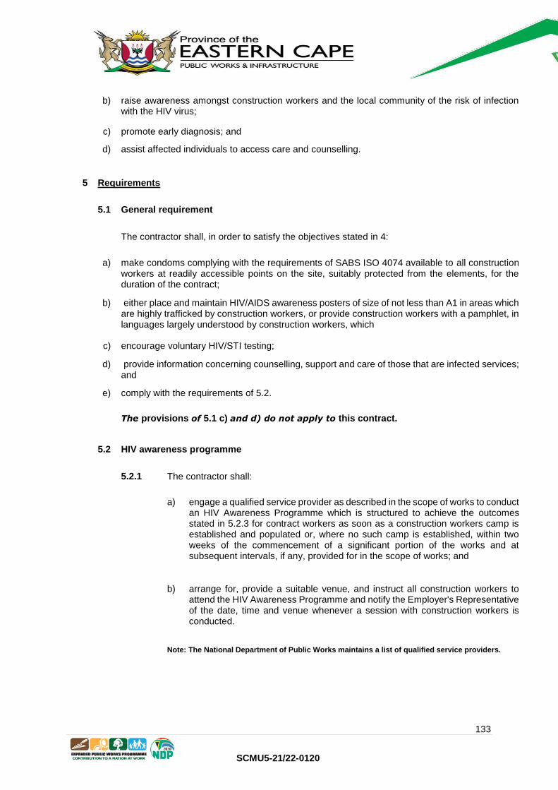
133
SCMU5-21/22-0120
b) raise awareness amongst construction workers and the local community of the risk of infection with the HIV virus;
c) promote early diagnosis; and
d) assist affected individuals to access care and counselling.
5 Requirements
5.1 General requirement
The contractor shall, in order to satisfy the objectives stated in 4:
a) make condoms complying with the requirements of SABS ISO 4074 available to all construction workers at readily accessible points on the site, suitably protected from the elements, for the duration of the contract;
b) either place and maintain HIV/AIDS awareness posters of size of not less than A1 in areas which are highly trafficked by construction workers, or provide construction workers with a pamphlet, in languages largely understood by construction workers, which
c) encourage voluntary HIV/STI testing;
d) provide information concerning counselling, support and care of those that are infected services; and
e) comply with the requirements of 5.2.
The provisions of 5.1 c) and d) do not apply to this contract.
5.2 HIV awareness programme
5.2.1 The contractor shall:
a) engage a qualified service provider as described in the scope of works to conduct an HIV Awareness Programme which is structured to achieve the outcomes stated in 5.2.3 for contract workers as soon as a construction workers camp is established and populated or, where no such camp is established, within two weeks of the commencement of a significant portion of the works and at subsequent intervals, if any, provided for in the scope of works; and
b) arrange for, provide a suitable venue, and instruct all construction workers to attend the HIV Awareness Programme and notify the Employer's Representative of the date, time and venue whenever a session with construction workers is conducted.
Note: The National Department of Public Works maintains a list of qualified service providers.

134
SCMU5-21/22-0120
5.2.2 The contractor shall do nothing to dissuade construction workers from attending such an HIV Awareness Programme and shall take all reasonable steps to ensure that a minimum of 90% of construction workers engaged in the works attend such a programme, when it is conducted.
5.2.3 The outcomes of the HIV Awareness Programme shall as a minimum, result in contract workers exposed to such a programme being able to:
a) communicate the existence of problems of HIV and be able to outline the consequences of transmission of HIV to or from the local community;
b) recall and communicate the mode of HIV transmission and preventative measures including the proper use of the condom.
HIV/STI COMPLIANCE REPORT
Pro-forma reporting format in terms of the SPECIFICATION FOR HIV/AIDS AWARENESS
SCMU number:
Payment Claim number:
Period covered by payment
claim:
1. Distribution of condoms (briefly describe where and how condoms are distributed).
2. Posters / pamphlets (briefly describe where posters were placed / how pamphlets were distributed).

135
SCMU5-21/22-0120
3. Voluntary testing (briefly describe the actions taken / information provided to promote testing).
4. Counselling, support and care (summarise information provided).
5. HIV awareness programme (briefly describe action).
6. Schedule of construction workers exposed to the HIV awareness programme.
Name Identity number Trade / occupati
on
Name of employer
NOT APPLICABLE
NOT APPLICABLE

136
SCMU5-21/22-0120
I hereby declare the above to be a true reflection of actions taken to ensure compliance with the specification.
For Contractor:
Employer's representative:
Name:
Name:
Signature:
Signature:
Date:
Date:

137
SCMU5-21/22-0120
C1.5 Specification for developing skills that result in nationally accredited outcomes through infrastructure contracts
Version: September 2016
Issued by:

138
SCMU5-21/22-0120
Specification for developing skills that result in nationally accredited
outcomes through infrastructure contracts
Specification for developing skills that result in nationally accredited outcomes through infrastructure contracts
1 Scope
This specification establishes a key performance indicator in the form of a contract skills development goal (CSDG) relating to the structured work learning component of occupational or professional learning, which enables learners to make measurable progress towards the attainment of:
a) a part or full occupational qualification registered on the National Qualification Framework, b) a trade qualification leading to a listed trade (GG No. 35625, 31 August 2012); c) a national diploma registered on the National Qualification Framework; or d) registration in a professional category by a recognized professional body or statutory council. in the delivery, maintenance and operation of infrastructure through the performance of professional service, service, supply or engineering and construction works contracts or an order associated with such a contract. This specification sets out the methods by which the key performance indicator is established, measured, quantified and verified in the performance of the contract or the execution of an order. NOTE This specification can be applied to contracts or to orders (call-offs) issued in terms of framework agreements. Framework agreements
are well suited to situations in which long term relationships are entered into. They offer flexibility in attaining contract skills development
goals as requirements can be adjusted from one order to another, thus allowing key performance indicators to be improved upon over time.
2 Terms and definitions
For the purposes of this document, the following terms and definitions apply: allowance amount provided for in the contract or an order by the employer relating to one or more of the following: a) the performance by the contractor of work or services that are foreseen but cannot be accurately
specified at the time that the contract was entered into or the order issued;
b) work or services to be performed, or goods provided, by a subcontractor who is either nominated by the employer or is selected by the employer in consultation with the contractor after the award of the contract or the issuing of an order;
c) provision for price adjustment for inflation; or
d) other budgetary provisions intended to cover the employer’s contractual risks
artisan a person who has been certified as competent to perform a listed trade in accordance with Section 26B of the Skills Development Act of 1998 (Act No. 97 of 1998)
black people

139
SCMU5-21/22-0120
a generic term which means Africans, Coloureds and Indians and who are citizens of the Republic of South Africa: a) by birth or descent; or
b) by naturalisation before 27 April 1994 or on or after 27 April 1994 and who would have been entitled to acquire citizenship by naturalisation prior to that date
candidate a person who is registered in a category of registration which ultimately leads to registration in a professional category by a statutory council in terms of their founding legislation class of construction works the class of construction works referred to in Schedule 3 of the Construction Industry Development Regulations 2004 as amended and published in terms of the Construction Industry Development Board Act of 2000 (Act 38 of 2000) contract amount financial value of the contract at the time of the award of the contract or the issuing of an order, excluding all allowances and expenses and value added tax contract skills development goal (CSDG) the number of hours of skills development opportunities that a contractor contracts to provide in relation to work directly related to the contract or order up to: a) completion in the case of a professional service contract;
b) the end of the service period in the case of a service contract; c) completion (state of readiness for occupation of the whole works although some minor work
may be outstanding) in the case of an engineering and construction works contract; and d) the delivery date for all the work required in terms of the supply contract contractor person or organization that contracts to provide the goods, services or engineering and construction works covered by the contract employer person or organization intending to or entering into the contract with the contractor for the provision of goods, services, or engineering and construction works employer's representative person authorized to represent the employer in terms of the contract engineering and construction works contract contract for the provision of a combination of goods and services arranged for the development, extension, refurbishment, rehabilitation or demolition of a fixed asset, including building and engineering infrastructure expenses costs incurred by the contractor in the performance of the contract or order which are in terms of the contract recoverable from the employer framework agreement

140
SCMU5-21/22-0120
an agreement between an organ of state and one or more contractors, the purpose of which is to establish the terms governing orders to be awarded during a given period, in particular with regard to price and, where appropriate, the quantity envisaged. mentor a qualified, experienced and, in the case of professionals, registered person, designated to guide a learner or candidate through a structured work experience learning component of a learning programme required for the acquisition of a part or full qualification or professional designation occupational qualification occupational qualification registered on the National Qualifications Framework Act (Act No 67 of 2008) order an instruction to provide goods, services or any combination thereof under a framework agreement part qualification an assessed unit of learning that is registered on the National Qualifications Framework as part of an occupational qualification professional category a category of registration identified in Table 1 or such other category recognized by the Employer in the application of this specification Table 1: Categories of registration
Profession Category of registration Act
Architectural
Architect, Senior Architectural Technologist, Architectural Technologist or Architectural Draughts person
Architectural Profession Act of 2000 (Act No. 44 of 2000)
Construction project management
Construction Project Manager Project and Construction Management Professions Act of 2000 (Act No. 48 of 2000) Construction management Construction Manager
Engineering Engineer , Engineering Technologist, Engineering Technician or Certificated Engineer
Engineering Profession Act of 2000 (Act No. 46 of 2000)
Landscape Architectural Landscape Architect, Landscape Technologist, Landscape Technician or Landscape Assistant
Landscape Architectural Profession Act of 2000 (Act No. 45 of 2000)
Quantity surveying Quantity surveyor Quantity Surveying Profession Act of 2000 (Act No. 49 of 2000)
Scientists Natural scientists Natural Scientific Professions Act (Act No. 27 of 2003)
Surveying Land surveyor, Engineering surveyor or Technician engineering surveyor
Professional and Technical Surveyors' Act (Act No. 40 of 1984)
professional service contract contract for the provision of services with the skill and care normally delivered by professionals Sector Education and Training Authority (SETA)

141
SCMU5-21/22-0120
an institution established under section 9 of the Skills Development Act, Act 97 of 1998 and which has the responsibility under this Act to register learners on learning programed service contract contract for the provision of labour or work, including knowledge-based expertise, carried out by hand or with the assistance of equipment and plant site means the land or place made available by the employer, for the purposes of the contract or order, on, under, over, in or through which the works or services are to be executed skills development agency an agency which performs some or all of the functions set out in section 4.1.4. statutory council a council as established under the a) South African Council for the Architectural Profession, established by the Architectural Profession
Act of 2000 (Act No. 44 of 2000);
b) South African Council for the Project and Construction Management Professions, established by the Project and Construction Management Professions Act of 2000 (Act No. 48 of 2000);
c) Engineering Council of South Africa, established by the Engineering Profession Act of 2000 (Act
No. 46 of 2000); d) South African Council for the Landscape Architectural Profession, established by the Landscape
Architectural Profession Act of 2000 (Act No. 45 of 2000); e) South African Council for the Quantity Surveying Profession, established by the Quantity
Surveying Profession Act of 2000 (Act No. 49 of 2000); f) South African Council for Professional and Technical Surveyors, established by the Professional
and Technical Surveyors' of 2000 (Act No. 40 of 1984); or g) South African Council for Natural Scientific Professions, established by the Natural Scientific
Professions Act (Act No. 27 of 2003): structured mentorship mentorship provided by a person who is registered in a suitable category of professional registration by a statutory council or professional body which leads and directs a candidate towards professional registration structured work experience learning component component of learning in an occupational qualification or for professional designation whereby a learner is mentored by a qualified, and where required, registered mentor in the application and integration of the knowledge and practical skills learnt, under supervision, in the actual context of a workplace in accordance with the prescripts set by the relevant qualifying authority, professional body or statutory council. supervisor a supervisor is a person in the particular workplace charged with the responsibility of allocating workplace tasks to a learner that are aligned to the prescriptions of their learning programme and of overseeing and reporting on that learning using a formally agreed record keeping system supply contract contract for the provision of goods and associated services including design

142
SCMU5-21/22-0120
work integrated learning the workplace learning component required by learners completing a national diploma at a University of Technology or Comprehensive University.
3 Requirements
3.1 Contract skills development goal (CSDG)
3.1.1 The contractor shall attain or exceed the contract skills development goal in the performance of the contract or the execution of an order. 3.1.2 The contract skills development goal shall be not less than: a) the contract amount in millions of Rand multiplied by:
1) the relevant number of hours per million Rand expenditure contained in Table 2 in the case of engineering and construction works contracts for the applicable class of construction works used in the application of the Construction Industry Development Regulations issued in terms of the Construction Industry Development Board Act of 2000; or
2) 300 in the case of a service contract; or
3) 100 in the case of a professional service contract or a supply contract; or
b) the hours tendered in the preference schedule or the quantum agreed in the scope of work of the contract or order.
Example: The contract amount for an engineering and construction works contract in the GB class of construction works is R65,7 million. The contract skills development goal is 65,7 x 250 = 16 425 hours. Table 2: Number of hours per million Rand expenditure in an engineering and construction work contract
Class of construction works as identified in terms of Regulation 25(3) of the Construction Industry Regulations 2004
Number of hours per million Rand expenditure
Designation
Description
CE Civil engineering 125
CE or GB Civil Engineering or general building 190
EE Electrical engineering works (buildings) 125
EP Electrical engineering works (Infrastructure) 125
GB General building 250
ME Mechanical engineering works 125
SB Specialist 125
3.1.5 Where required in terms of the contract or order, a specified proportion of the learners and candidates shall be selected from a list of persons in the employ of the state contained in the scope of work of the contract or order under the terms and conditions embodied therein.

143
SCMU5-21/22-0120
NOTE: The contract skills development goal can be achieved through the direct employment of persons who are developing skills that result
in nationally accredited outcomes, through the engagement of subcontractors who employ such persons or, where specifically required, the
provision of work place opportunities to employees of the state.
3.2 Achieving the contract skills development goal (CSDG)
3.2.1 The contractor shall achieve the measurable contract skills development goal by providing one or a combination of any of the following in relation to work directly related to the contract or order: Method 1: structured work experience learning component opportunities for learners towards the attainment of a part qualification or a full occupational qualification; Method 2: structured work experience learning component opportunities for apprentices or other artisan learners towards the attainment of a trade qualification leading to a listed trade (GG No. 35625, 31 August 2012) subject to at least 60% of the artisan learners being holders of public FET college qualifications; Method 3: work integrated learning opportunities for University of Technology or Comprehensive University students completing their national diplomas; Method 4: structured work experience opportunities for candidates towards registration in a professional category by a recognized professional body or statutory council. 3.2.2 No single method, except in the case of professional service contracts, shall contribute more than 75 percent of the contract skills development goal, Method 1 shall not contribute to more than 25 percent of the contract skills development goal in engineering and construction works or service contract and related orders. 3.2.3 Not more than one method may be applied to any individual in the calculation of the contract skills development goal. NOTE: The principle is that an individual can only be counted once towards the CSDG.
3.3 Contract skills development goal credits
3.3.1 Credits towards the contract skills development goal shall be granted by summating the hours of opportunities provided in accordance with this specification. 3.3.2 No more than 8 hours may be claimed for any 24 hour period for any individual. 3.3.3 Contract skills development goal credits shall be reduced to the extent that they fail to comply with the requirements of this specification.
3.4 Denial of credits
Credits towards the contract skills development goal shall be denied should: a) the opportunities not be provided on site or the opportunities cannot be directly linked to the
contract or order; b) the following not be provided:
1) the required contract compliance baseline plan, an interim contract compliance report or a final contract compliance report;

144
SCMU5-21/22-0120
2) the required mentorship plan for a candidate; 3) the required training plan for learners; 4) the training reports covering a period; or
5) the required records, specified documents and signatures;
c) the structured mentorship be found not to be in accordance with the requirements of the applicable professional body, statutory council or qualifying authority;
d) the structured work experience learning component be found not to be in accordance with the curriculum requirements of the part qualification or qualification or prescription for professional registration for which the learner is registered;
e) conditions of employment and rates or allowances for learners not be in accordance with legislative provisions;
f) the contractor does not maintain the required training records or an audit reveals that there is
insufficient information to substantiate claims for credits; and
g) a learner, learner artisan or candidate fails to present their credentials for assessment when they have, in the opinion of the mentor, sufficient structured work experience or structured mentorship to do so.
4 Compliance with requirements
4.1 General
4.1.1 The contractor shall submit to the employer’s representative: a) within 30 days of the contract coming into effect or the issuing of an order, a contract compliance
base line training plan (see Annex A) taking into account the skills mix and type of workers that are to be engaged;
b) interim contract compliance training reports (see Annex A) at intervals which do not exceed 3 months;
c) a final contract compliance training report (see Annex A) within 15 days of reaching completion, final delivery or the end of the service as relevant; and
d) a report which provides a breakdown of the number of hours reported in each interim and in the final contract compliance report into black people and women and people with disabilities.
NOTE: The Code of Good Practice on Key Aspects of Disability in the Workplace issued in terms of Employment Equity Act No 55, OF 1998 provides guidance on establishing who are people with disabilities. 4.1.2 The contractor shall keep records of the name and identity number, hours worked, payments made to, registration particulars towards a part qualification or occupational qualification and particulars of opportunities offered to persons who are provided with work experience learning component opportunities which contribute to the contract skills development goal and any other training records required by or which demonstrate compliance with this specification. The contractor shall allow the employer’s representative to inspect or audit such training records at any time within working hours.

145
SCMU5-21/22-0120
4.1.3 The employer’s representative shall undertake suitable random audits on records to confirm compliance with requirements. 4.1.4 Where learners are sourced through a Skills Development Agency (SDA), the contractor shall enter into a contract agreement with one or more SDAs of their choice that is participating in the implementation of this specification to, as relevant: a) facilitate placement of learners for training opportunities;
b) prepare training plans for registered learners, including details of the scope of experiential work to be covered and expected outcomes;
c) register learners with the appropriate sector Education and Training Authority established in terms of the Skills Development Act of 2008 (Act 37 of 2008);
d) manage all the employment functions of learners such as payment of stipends, contributions to the Unemployment Insurance Fund, Workman’s Compensation, provision of personal protective clothing, trade specific tools, etc.;
e) liaise with the training co-ordinators to monitor onsite training progress of learners;
f) liaise with the training co-ordinators to arrange for summative assessments at appropriate stages of the training; and
g) liaise with the training co-ordinators to prepare reports for the employer or employer’s representative.
4.2 Structured workplace learning opportunities for learners
4.2.1 Structured work experience learning component opportunities shall be aligned to the curriculum requirements set for the particular part or full occupational qualification or professional designation for which the learner is registered. 4.2.2 A responsible supervisor shall be appointed to allocate learning tasks, under the guidance of a qualified person, to learners in line with their training plans 4.2.3 Mentoring associated with structured work experience learning component for artisan learners shall be undertaken by an artisan qualified in the applicable trade with a minimum of 3 years of trade related experience. The number of artisan learners mentored by a single mentor shall, unless otherwise permitted by the National Artisan Moderation Body, not exceed 4 at any one time. 4.2.4 Mentoring associated with structured work experience learning component for learners leading to a part or an occupational qualification other than artisan learners shall be undertaken by a person qualified in the applicable discipline with a minimum of 3 years of experience. 4.2.5 The contractor or service provider shall submit to the employer’s representative, in respect of each learner: a) within one month of commencing work directly related to the contract or order, a workplace
training plan together with name of the learner’s mentor and supervisor
b) within three months of commencing work directly related to the contract or order:
1) proof of registration as a learner with the relevant SETA; and

146
SCMU5-21/22-0120
2) a copy of the mentorship agreement entered into with the learner or the company mentorship agreement entered into with the relevant qualified agency;
c) within two weeks of updating a workplace training plan, the revised workplace training plan; and
d) a quarterly progress report and a final report at the end of the structured mentorship period including a log of exposure and interactions with the mentor in sufficient detail to demonstrate compliance with requirements, signed off by the mentor, the supervisor and the learner.
4.2.6 Learners shall be required by the mentor to complete training reports required by the relevant qualifying authority whenever a substantial activity or training period has been completed. 4.2.7 The mentor and supervisor shall sign off all reports and logbooks to allow the learner to move to other projects or employment and continue on the path towards qualification and, where relevant registration, where the work related to the contract ends for whatever reason prior to the learner gaining sufficient experience for final assessment.
4.3 Structured mentorship opportunities for candidates
4.3.1 Mentoring associated with structured work experience for candidates shall be in accordance with the prescripts of the relevant professional body or statutory council. 4.3.2 The contractor shall: a) appoint a supervisor who is actively engaged in work directly associated with the contract to issue
tasks, oversee their implementation and provide input to the candidate on an on-going basis;
b) identify a suitable mentor for the candidate, if such candidate does not have a mentor, who shall enter into a mentoring agreement with the candidate or the company as required by the professional body or statutory council; and
c) issue each candidate with a portfolio of evidence file which is to be kept up to date with all the documentation issued or prepared including the workplace training plan and all revisions thereof as well as copies of the logbook entries and training period reports;
4.3.3 The mentor shall provide and update from time to time a workplace training plan for a candidate outlining the activities in which the candidate will be involved that includes activities required by the relevant statutory council. The mentor shall require candidates to maintain a logbook issued by the relevant statutory council. The mentor shall sign off such logbook at quarterly presentations and progress review meetings. NOTE: The mentor should ensure where the duration of the contract or order exceeds the minimum time to register in a professional category of registration that candidates are exposed to the full range of activities and work towards assuming the full level of responsibility recommended by the relevant statutory council. This may require rotations and secondments. 4.3.4 The contractor or service provider shall submit to the employer’s representative, in respect of each candidate: a) within one month of commencing work directly related to the contract or order:
1) a workplace training plan together with name of the candidate’s mentor and supervisor
2) proof of registration as a candidate with the relevant professional body or statutory council; and

147
SCMU5-21/22-0120
3) a copy of the mentorship agreement entered into with the candidate or the company
mentorship agreement entered into with a professional body or statutory council; b) within two weeks of updating a workplace training plan, the revised workplace training plan.
c) a quarterly progress reports and a final report at the end of the structured mentorship period including a log of exposure and interactions with the mentor in sufficient detail to demonstrate compliance with requirements, signed off by the mentor, the supervisor and the candidate.
4.3.5 Candidates shall be required by the mentor to complete training reports required by the relevant statutory council whenever a substantial activity or training period has been completed. 4.3.6 The mentor and supervisor shall sign off all reports and logbooks to allow the candidate to move to other projects or employment and continue on the path towards registration where the work related to the contract ends for whatever reason prior to the candidate gaining sufficient experience for registration.
5 Records
5.1 The contractor shall submit all the documentation required in terms of clause 4 in a timely manner. 5.2 The employer's representative shall certify the value of the credits counted towards the contract skills development goal, if any, whenever a claim for payment is issued to the employer, and shall notify the contractor of this amount. 5.3 The contractor shall, upon termination of the opportunities provided in order to satisfy the contract skills development goal, certify the quantum and nature of the opportunity and submit the certificate, counter-certified by the relevant individual, to the employer's representative for record-keeping purposes.
6 Sanctions
In the event that the contractor fails to substantiate that any failure to achieve the contract skills development goal was due to reason beyond the contractor's control which may be acceptable to the employer, the sanctions provided for in the contract or order shall apply.
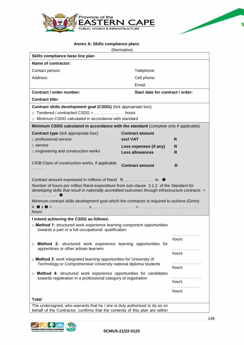
148
SCMU5-21/22-0120
Annex A: Skills compliance plans
(Normative)
Skills compliance base line plan
Name of contractor:
Contact person: Telephone:
Address: Cell phone:
Email:
Contract / order number: Start date for contract / order:
Contract title:
Contract skills development goal (CSDG) (tick appropriate box)
□ Tendered / contracted CSDG = . . . . . . . . . . . . . hours
□ Minimum CSDG calculated in accordance with standard
Minimum CSDG calculated in accordance with the standard (complete only if applicable)
Contract type (tick appropriate box):
□ professional service
□ service
□ engineering and construction works
CIDB Class of construction works, if applicable . . . . . .
Contract amount
excl VAT R
Less expenses (if any) R
Less allowances R
Contract amount R
Contract amount expressed in millions of Rand R . . . . . . . . . . . . . m
Number of hours per million Rand expenditure from sub-clause 3.1.2 of the Standard for developing skills that result in nationally accredited outcomes through infrastructure contracts = . . . . . . . . . . .
Minimum contract skills development goal which the contractor is required to achieve (Gmin)
= x = . . . . . . . . . . . . . . . . x . . . . . . . . . . . . . . . . . . = . . . . . . . . . . . . . . . . . . . . . . . . . . hours
I intend achieving the CSDG as follows:
□ Method 1: structured work experience learning component opportunities towards a part or a full occupational qualification
. . . . . . . . . . . . hours
□ Method 2: structured work experience learning opportunities for apprentices or other artisan learners
. . . . . . . . . . . . hours
□ Method 3: work integrated learning opportunities for University of Technology or Comprehensive University national diploma students
. . . . . . . . . . . . . hours
□ Method 4: structured work experience opportunities for candidates towards registration in a professional category of registration
. . . . . . . . . . . . . hours
Total
. . . . . . . . . . . . hours
The undersigned, who warrants that he / she is duly authorised to do so on behalf of the Contractor, confirms that the contents of this plan are within

149
SCMU5-21/22-0120
my personal knowledge and are to the best of my belief both true and correct.
Signed Date
Name
Position

150
SCMU5-21/22-0120
Skills compliance report Date:
(tick appropriate box) □ Interim report □ Final report
Name of contractor:
Contact person: Telephone
Address: Cell phone
Contract / order number: Start date for contract / order:
Contract title:
Contract skills development goal (CSDG) . . . . . . . . . . . . hours
Method 1: structured workplace experience learning component opportunities towards a part or a full occupational qualification
Employed by contractor
Name
Identity or passport number
Cell or telephone number
Part or full occupational qualification
NQF ref. no.
Student number
SETA with whom learner is registered
Dates for engagement on work related to contract
Total hours
Start End
Employed by subcontractor: (state name)
Name
Identity or passport number
Cell or telephone number
Part or full occupational qualification
NQF ref. no.
Student number
SETA with whom learner is registered
Dates for engagement on work related to contract
Total hours
Start End
Method 2: structured work experience learning component opportunities for apprentices or other artisan learners
Employed by contractor
Name
Identity or passport number
Cell or telephone number
Listed trade
National artisan learner data base registration number (where available)
SETA with whom the learner is registered
Dates for engagement on works related to contract
Total hours
Start End
Employed by subcontractor: (state name)

151
SCMU5-21/22-0120
Name
Identity or passport number
Cell or telephone number
Listed trade
National artisan learner data base registration number (where available)
SETA with whom the learner is registered
Dates for engagement on works related to contract
Total hours
Start End
Method 3: work integrated learning opportunities for University of Technology (UOT) or Comprehensive University (CU) diploma students
Employed by contractor
Name
Identify or passport number
Cell or telephone number
Diploma
Learner registration number
UOT/CU with whom the learner is registered
Date for engagement on contract
Total hours
Start End
Employed by sub-contractor
Name
Identify or passport number
Cell or telephone number
Diploma
Learner registration number
UOT/CU with whom the learner is registered
Date for engagement on contract
Total hours
Method 4: structured work experience opportunities for candidates towards registration in a professional category of registration
Employed by contractor
Name
Identity or passport number
Cell or telephone number
Statutory council particulars Dates for engagement on work related to contract
Total hours
Title Registration number
Start End
Employed by subcontractor
Cell or telepho
Statutory council particulars Dates for engagement on

152
SCMU5-21/22-0120
Name
Identity or passport number
ne number
work related to contract
Total hours
Title Registration number
Start End
The undersigned, who warrants that he / she is duly authorised to do so on behalf of the Contractor, confirms that the contents of this plan are within my personal knowledge and are to the best of my belief both true and correct.
Signed Date
Name Position

153
SCMU5-21/22-0120
Annex B: Incorporating this specification in a procurement document
B1 General
B1.1 The following clause should be added to the scope of work of a contract or order to establish requirements: Skills development requirements The contractor shall achieve in the performance of the contract the contract skills development goal established in the Department of Higher Education and Training’s Standard for developing skills that result in nationally accredited outcomes through infrastructure contracts (September 2012)
Note: The term contractor may need to be changed to “consultant” or “professional service provider” depending upon the term that is used in the form of contract that is adopted. The term “performance of the contract” may need to be replaced with “execution of an order” where the scope of work forms part of an order. B1.2 Where an employer requires that employees of the state be seconded to the contractor in order to be provided with work integrated learning opportunities, structured workplace experience opportunities or structured mentorship opportunities in accordance with the provisions of this standard, the following clause should be included in the scope of work:
The specified proportion of employees of the state is . . . . . . %. Work integrated learning opportunities / structured workplace experience opportunities / structured mentorship opportunities shall be offered to any of the persons identified in Annexure 1. Persons selected by the contractor from the list in Annexure 1 shall be seconded to the contractor under the following terms and conditions: . . . . . . . . . . . . . . . . . . .
NOTE: The annexure should inform the contractor of the opportunities which the named employees of the state require through the contract or order in order to attain a nationally accredited outcome.
B2 Financial incentives
Financial incentives may be offered to contractors should they exceed a key performance indicator (KPI) in the performance a contract in the form of a contract skills development goal in accordance with the requirements of this standard which can be agreed to either through a negotiation process before or after a contract or order is awarded. Financial incentives should not be confused for preferences for rewarding contactors for offering to achieve a deliverable and a financial penalty (low performance damages) for failing to deliver on obligations. The intention for offering financial incentives for the attainment of KPIs is to encourage, rather than coerce, the contractor to meet and exceed the employer’s objectives. Financial incentives can be formulated in a number of ways. The most common way is to make them linearly proportional to increases in contract participation goals. Stepped incentives may also be used. Consideration should be given to capping the quantum of the financial incentive. Option X20 (Key Performance Indicators) of the NEC3 Engineering and Construction Contract, NEC3 Professional Service Contract and the NEC3 Term Service Contract makes provision for a contractor to be paid an amount stated in an incentive schedule if the target stated for a key performance indicator is improved upon or achieved. Additional conditions of contact need to be framed and included in the contract data where use is made of other forms of contract.

154
SCMU5-21/22-0120
Note: Financial incentives are usually used where tenderers are not invited to tender contract skills development goals, but are required to accept a minimum contract skills development goal and are rewarded for performance beyond the minimum.
B3 Sanctions
Sanctions should be provided for in the contract in the event that the contractor fails to substantiate that any failure to achieve the contract participation goal was due to quantitative under runs, the elimination of items, or any other reason beyond the contractor’s control which may be acceptable to the employer. Appropriate action should be taken by employers against tenderers who are awarded contracts in preference to others on a fraudulent basis or against contractors who fail to achieve their contractual obligations relating to the development of skills. Employers have a number of sanctions and contractual remedies available to address such situations, including the iimposition of a financial penalty (low performance damages) more severe than the financial preference calculated at the time when tenders were evaluated or more severe than complying with contractual obligations or not awarding future orders in terms of framework agreements.

155
SCMU5-21/22-0120
PART C2: PRICING DATA
C2.1 Pricing Assumptions
C2.2 Pricing Schedule

156
SCMU5-21/22-0120
C2.1 Pricing Assumptions
Pricing Instructions mean the criteria as set out below, read together with all Parts of the contract document, which it will be deemed in the contract that the Tenderer has taken into account when developing his prices.
1. The rates, sums, percentage fees (as applicable) used by a Tenderer to determine his offer shall not exceed
the rates stipulated by the Guideline Scope of Services and Tariff of Fees for Persons Registered in terms
of the Engineering Profession Act 44 of 2000 and Department of Public Works: Rates for Reimbursable
Expenses document, respectively.
2. For the purpose of the Activity Schedule, the following words shall have the meanings hereby assigned to them:
Unit: The unit of measurement for each item of work.
Quantity: The number of units of work for each item.
Rate: The agreed payment per unit of measurement.
Amount: The product of the quantity and the agreed rate for an item.
Sum: An agreed lump sum payment amount for an item, the extent of which is described in the Scope of Work, but the quantity of work which is not measured in any units.
Percentage Fee: The agreed fee for a service, the extent of which is described in the Scope of Work, expressed as a percentage of a construction contract value or part thereof.
3. A rate, sum, percentage fee and/or price as applicable, is to be entered against each item in the Activity
Schedule. An item against which no price is entered will be considered to be covered by the other prices or rates in the Activity Schedule.
4. The rates, sums, percentage fees and prices in the Activity Schedule are to be fully inclusive prices for the
work described under the several items. Such prices and rates are to cover all costs and expenses that
may be required in and for the execution of the work described in accordance with the provisions of the
Scope of Work, and shall cover the cost of all general risks, liabilities, and obligations set forth or implied in
the Contract Data, as well as overhead charges and profit. Where time-based rates are quoted, such shall
include for all payments to administrative, clerical and secretarial staff used to support professional and
technical staff.
5. Where quantities are given in the Pricing Schedule, these are provisional and do not necessarily represent the actual amount of work to be done. The quantities of work accepted and certified for payment will be used for determining payments due and not the quantities given in the Activity Schedule. In respect of time based services, the allocation of staff must be agreed with the employer before such services are rendered.
6. All other rates, sums, percentage fees or prices (as applicable) tendered in the Activity Schedule shall be
final and binding and shall not be subject to any variation throughout the period of the contract.
7. Tenderers are to note that the planning for this contract is based on three-year capital budget cycles which
are subject to change. While the Employer has every intention to complete the full scope of works, the
Employer reserves the right to reduce or increase the scope of works according to the dictates of the budget,

157
SCMU5-21/22-0120
or to terminate this contract, without adjustment to the agreed rates, sums or fees and without payment of
any penalty or surcharge in this regard. The Service Provider shall however be entitled to pro-rata payment
for all services carried out in terms of any adjustment to the Scope of Work or, in the case of termination,
remuneration and/or reimbursement as described in Clause 8.4.4 of the Standard Professional Services
Contract.
8. The per kilometre rate for the reimbursement of travel expenses shall be as per the Department of Public
Works: Rates for Reimbursable expenses available on http://www.publicworks.gov.za. It shall be noted that,
in respect of the aforementioned, the Employer shall only be liable for travel expenses with respect to
vehicles of engine capacity up to 1950cc only, for diesel and petrol fuelled engines respectively. If the
Service Provider elects to use a vehicle with engine capacity exceeding 1950cc, the Employer shall not be
liable for any additional cost resulting from a higher rate per kilometre associated with an engine capacity
larger than 1950cc and the rate per kilometre to be paid shall be deemed to be that of a 1950cc engine.
9. Distances for travelling to site for progress and technical meetings shall be remunerated on a kilometre
basis from the premises of the client to the location of the site on a round trip basis.
10. Rates for typing, printing, duplicating and drawings shall be as per the Department of Public Works: Rates
for Reimbursable expenses available on http://www.publicworks.gov.za
11. Tenderers are to note that only those recoverable expenses listed in the Activity Schedule will be reimbursed
to the Service Provider. No reimbursement of costs for subsistence, typing, printing/copying (other than
reports, tender documents, manuals, drawings and related schedules), communications, computer
hardware and/or software will be made and these costs will be deemed to be included in rates, sums,
percentages fees and prices for normal and additional services rendered.
12. Items for printing/copying shall be for specified contract documents, tender documents, reports, manuals,
drawings along with related schedules and shall exclude general correspondence, progress reports,
minutes of meetings etc which shall be deemed to be included in the professional fees as they are necessary
and integral to the execution of the Service Providers’ work as per the Standard Services for which it is
employed. Payment will only be made for copies of reports and drawings submitted to the employer and/or
issued to parties who bear an interest in the execution of the project, as specified or requested by the
Employer, and all drafts shall be for the Service Provider’s account.
13. Where provisional sums are provided in respect of additional services, these amounts may be omitted in
part or full should the additional work not be required and/or at the discretion of the Employer. Where
additional services are to be subcontracted out by the Service Provider, which do not exceed R30, 000.00
(including VAT) in value, the Service Provider will typically be required to invite three quotations from
suitably qualified sub-consultants/sub-contractors. Where the services are likely to exceed R30, 000.00
(including VAT), the Employer reserves the right to follow a procurement process relevant to its supply chain
management policy to procure such services in respect of this work. A mark-up in respect of all other costs,
overhead charges and profit will be applicable in respect of all sub-consultants at rates/percentages as
quoted by the Service Provider in the Activity Schedule.

158
SCMU5-21/22-0120
C2.2 Pricing schedules / Activity Schedule or Bills of Quantities
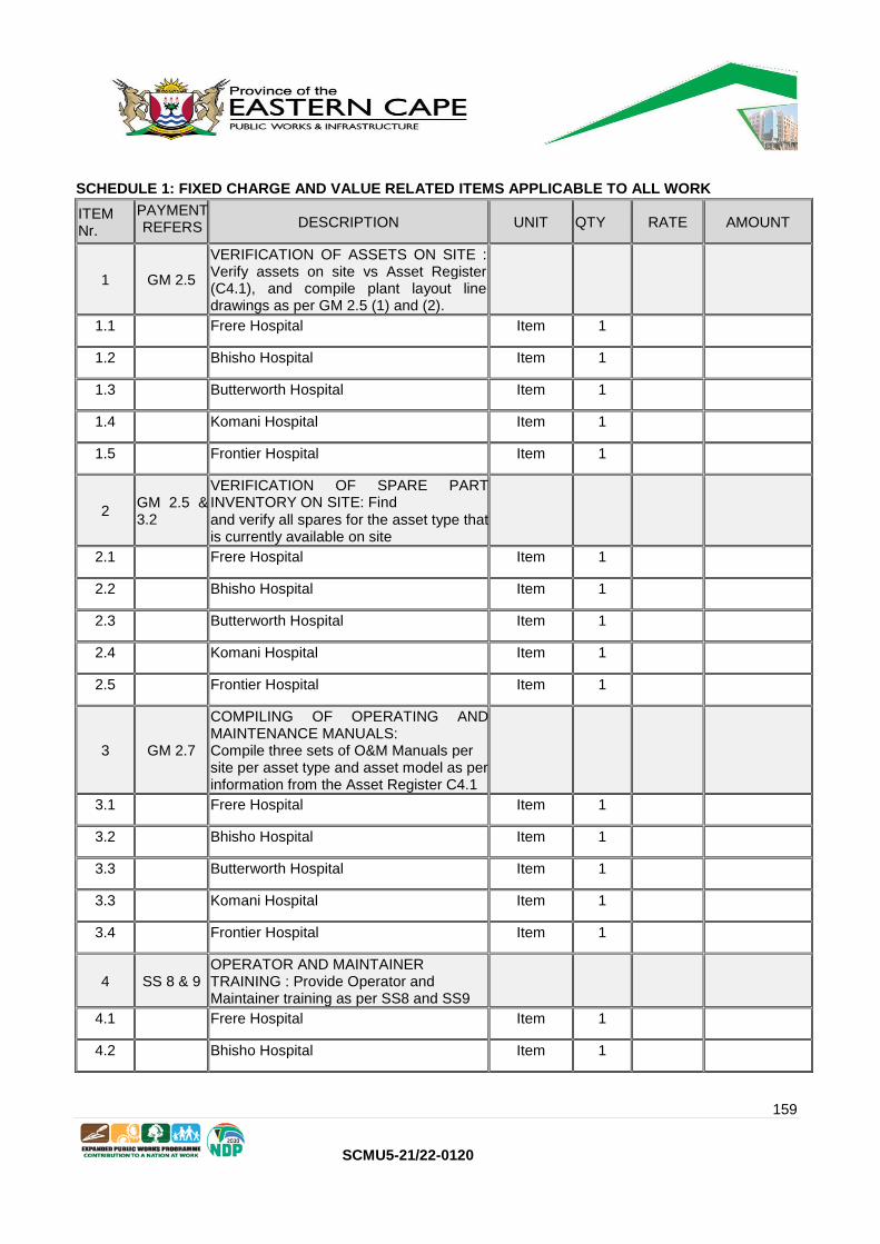
159
SCMU5-21/22-0120
SCHEDULE 1: FIXED CHARGE AND VALUE RELATED ITEMS APPLICABLE TO ALL WORK
ITEM Nr.
PAYMENT REFERS DESCRIPTION UNIT QTY RATE AMOUNT
1 GM 2.5
VERIFICATION OF ASSETS ON SITE : Verify assets on site vs Asset Register (C4.1), and compile plant layout line drawings as per GM 2.5 (1) and (2).
1.1 Frere Hospital Item 1
1.2 Bhisho Hospital Item 1
1.3 Butterworth Hospital Item 1
1.4 Komani Hospital Item 1
1.5 Frontier Hospital Item 1
2 GM 2.5 & 3.2
VERIFICATION OF SPARE PART INVENTORY ON SITE: Find
and verify all spares for the asset type that is currently available on site
2.1 Frere Hospital Item 1
2.2 Bhisho Hospital Item 1
2.3 Butterworth Hospital Item 1
2.4 Komani Hospital Item 1
2.5 Frontier Hospital Item 1
3 GM 2.7
COMPILING OF OPERATING AND MAINTENANCE MANUALS: Compile three sets of O&M Manuals per site per asset type and asset model as per information from the Asset Register C4.1
3.1 Frere Hospital Item 1
3.2 Bhisho Hospital Item 1
3.3 Butterworth Hospital Item 1
3.3 Komani Hospital Item 1
3.4 Frontier Hospital Item 1
4 SS 8 & 9 OPERATOR AND MAINTAINER TRAINING : Provide Operator and Maintainer training as per SS8 and SS9
4.1 Frere Hospital Item 1
4.2 Bhisho Hospital Item 1

160
SCMU5-21/22-0120
4.3 Butterworth Hospital Item 1
4.4 Komani Hospital Item 1
4.5 Frontier Hospital Item 1
5 GM 2.15
ENVIRONMENTAL MANAGEMENT PLAN : The Contractor must compile a basic Environmental plan specific to the type of work that he will be performing at the Health Facilities as per C3.2
Item 1
6 GM 2.15
OCCUPATIONAL HEALTH AND SAFETY ACT COMPLIANCE COST : The Contractor must comply to the project Health and Safety Specification specific to the type of work that he will be performing on site as per C3.2
Month 24
7 GM 2.16
HIV / AIDS AWARENESS PLAN : The Contractor must comply with all the requirements of the national Department of Public Works HIV / AIDS Specification (PW 1544) and provide pricing to cover all the requirements under this specification
Item 1
8 Clause 83.1
INSURANCE : LIMITATION OF LIABILITY (Amounts applicable for whole Contract)
8.1
Provision for General Contractor's Insurance (Minimum liability limit must be equal to R5,000 000) to cover requirements of Clause 83.1 in Contract Data
Month 24
9 X13 PERFORMANCE BOND (Amounts applicable for whole Contract)
9.1 Provision for a Performance bond of not
less than 2,5% of the Tender Value Month 24
10 GM 3
MAINTENANCE CONTROL PLAN: Compiling of a detailed Maintenance Control Plan for each Health Facility included in this Tender (See SS 3 for facility listing)
10.1 Frere Hospital Item 1
10.2 Bhisho Hospital Item 1
10.3 Butterworth Hospital Item 1
10.4 Komani Hospital Item 1
10.5 Frontier Hospital Item 1
11 SS15
IN-SERVICE TRAINING OF GRADUATES AND INTERNS: Provisional Sum to pay the costs associated with employing nominated

161
SCMU5-21/22-0120
Interns and Graduates for the duration of the Contract
11.1 In-Service TRAINING No 1 R85 00,00 R85 000,00
11.2 Graduates No 1 R144 000,00
R144 000,00
TOTAL CARRIED FORWARD TO SUMMARY
ASSET TYPE:BOILERS, STEAM AND CONDENSATE LINES, AND STEAM CALORIFIERS
SCHEDULE 2: FUNCTIONAL REPAIR SCHEDULE
ITEM Nr.
PAYMENT REFERS
DESCRIPTION UNIT QTY RATE AMOUNT
1 GM 2.5
FUNCTIONAL CONDITION ASSESSMENT: Perform Functional Condition Assessment (Inspection and Testing) on all listed assets at all Health Facilities included in the Tender
1.1 Frere Hospital Item 1
1.2 Bhisho Hospital Item 1
1.3 Butterworth Hospital Item 1
1.4 Komani Hospital Item 1
1.5 Frontier Hospital Item 1
2 GM 2.5.(5)
COMPILING OF PRICED SPARE PART LISTS: Compile detailed, comprehensive priced spare parts lists for each site and asset type (based on Contrcator's cost price). NOTE: The Employer retains the right to negotiate the offered spare part prices, if they are not in line with national price norms.
2.1 Frere Hospital Item 1
2.2 Bhisho Hospital Item 1
2.3 Butterworth Hospital Item 1
2.4 Komani Hospital Item 1
2.5 Frontier Hospital Item 1
3 GM 2.5
COMPILING OF DETAILED REPAIR SCHEDULE: Compile detailed, comprehensive repair schedule including defect description, recommended repair method, detailed quote including priced spare parts, outsourced work, and provisional work program, for each Health Facility and asset type.

162
SCMU5-21/22-0120
3.1 Frere Hospital Item 1
3.2 Bhisho Hospital Item 1
3.3 Butterworth Hospital Item 1
3.4 Komani Hospital Item 1
3.5 Frontier Hospital Item 1
4 GM 2.6
COMPILE FUNCTIONAL CONDITION ASSESSMENT REPORT: Compile Functional Condition Assessment Report for all asset types at all Health Facilities included in the Tender
4.1 Frere Hospital Item 1
4.2 Bhisho Hospital Item 1
4.3 Butterworth Hospital Item 1
4.4 Komani Hospital Item 1
4.5 Frontier Hospital Item 1
5 GM 6
PROVISION FOR SPECIAL TESTING BY SERVICE MANAGER
: Lump sum provision for doing special tests at the Health Facilities as per the prerogative of the Service Manager
PSum 1 R 140 000,
R 140 000,00
5.1 Clause 11.2(8)
Direct Fee Percentage (Mark-up) to be charged by Contractor on amounts above %
6 GM 2.6
MAINTENANCEDOCUMENTATIONSITE STORAGE CONSOLE: Provisional sum to supply and install O&M Manual, Log Books, and site Maintenance Records at each equipment
type location as directed by the Service Manager
PSum 1 R 3 500,00
R 3 500,00
TOTAL CARRIED FORWARD TO SUMMARY

163
SCMU5-21/22-0120
SCHEDULE 3 A: MAINTENANCE SERVICE SCHEDULE
ITEM Nr.
PAYMENT REFERS DESCRIPTION UNIT QTY RATE AMOUNT
1 GM 3.2
MAINTENANCE WORKS : Standard servicing and planned Maintenance Costs including all parts, consumables and lubricants, labour, travelling, accommodation and subsistence allowances (Priced per machine or equipment grouping)
1.1 GM 3.2 Frere Hospital: Boilers
1.1.1 GM 3.2 Minor Service Cost : Price per Monthly Inspection per machine, as per tasks from the Monthly Service Inspection Guideline in C6.
No 46
1.1.2 GM 3.2
Major Service Cost: Price per Annual Service /
Inspection per machine, as per tasks from the
Annual Service Inspection
Guideline in C6.
No 4
1.1.3 GM 3.2 Statutory Inspection (3 yearly) If no records are found on site a statutory inspection must be done ASAP after site hand over.
No 2
1.1.4 SS 1 Supply Boiler Operator (1 per shift) for 24/7 operation of the Boiler Plant (All-inclusive Rate/month)
No 24
1.1.5 SS1 Supply boiler water treatment plant chemicals for duration of the Contract (monthly cost) No 24
1.2 GM 3.2 Frere Hospital: Steam and Condensate Lines
1.2.1 GM 3.2 Minor Service Cost : Price per Monthly inspection per machine, as per tasks from the Monthly Service Inspection Guideline in C6.
No 24
1.3 GM 3.2 Frere Hospital: Steam Calorifiers
1.3.1 GM 3.2
Major Service Cost: Price per Annual Service /
Inspection per machine, as per tasks from the
Annual Service Inspection
Guideline in C6.
No 42
1.4 GM 3.2 Bhisho Hospital: Boilers
1.4.1 GM 3.2 Minor Service Cost : Price per Monthly Inspection per machine, as per tasks from the Monthly Service Inspection Guideline in C6.
No 46
1.4.2 GM 3.2
Major Service Cost: Price per Annual Service /
Inspection per machine, as per tasks from the
Annual Service Inspection
Guideline in C6.
No 4
1.4.3 GM 3.2 Statutory Inspection (3 yearly) If no records are found on site a statutory inspection must be done ASAP after site hand over.
No 2
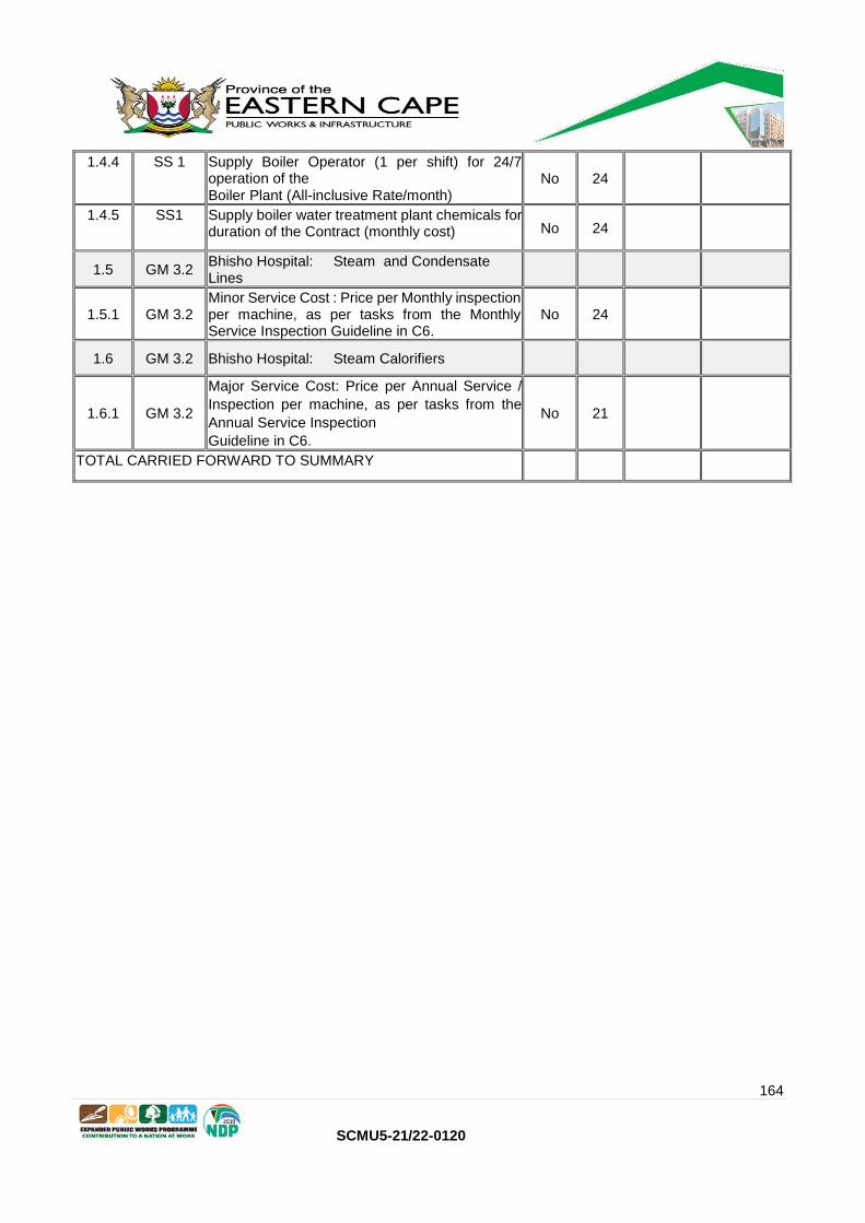
164
SCMU5-21/22-0120
1.4.4 SS 1 Supply Boiler Operator (1 per shift) for 24/7 operation of the Boiler Plant (All-inclusive Rate/month)
No 24
1.4.5 SS1 Supply boiler water treatment plant chemicals for duration of the Contract (monthly cost) No 24
1.5 GM 3.2 Bhisho Hospital: Steam and Condensate Lines
1.5.1 GM 3.2 Minor Service Cost : Price per Monthly inspection per machine, as per tasks from the Monthly Service Inspection Guideline in C6.
No 24
1.6 GM 3.2 Bhisho Hospital: Steam Calorifiers
1.6.1 GM 3.2
Major Service Cost: Price per Annual Service /
Inspection per machine, as per tasks from the
Annual Service Inspection
Guideline in C6.
No 21
TOTAL CARRIED FORWARD TO SUMMARY

165
SCMU5-21/22-0120
SCHEDULE 3 B: MAINTENANCE SERVICE SCHEDULE (CONTINUED)
ITEM Nr.
PAYMENT REFERS DESCRIPTION UNIT QTY RATE AMOUNT
1.7 GM 3.2 Butterworth Hospital: Boilers
1.7.1 GM 3.2 Minor Service Cost : Price per Monthly Inspection per machine, as per tasks from the Monthly Service Inspection Guideline in C6.
No 35
1.7.2 GM 3.2
Major Service Cost : Price per Annual Service /
Inspection per machine, as per tasks from the
Annual Service Inspection
Guideline in C6.
No 2
1.7.3 GM 3.2 Statutory Inspection (3 yearly) If no records are found on site a statutory inspection must be done ASAP after site hand over.
No 2
1.7.4 SS 1 Supply Boiler Operator (1 per shift) for 24/7 operation of the
Boiler Plant (All-inclusive Rate/month)
No 24
1.7.5 SS1 Supply boiler water treatment plant chemicals for duration of the Contract (monthly cost)
No 24
1.8 GM 3.2 Butterworth Hospital: Steam and Condensate Lines
1.8.1 GM 3.2 Minor Service Cost : Price per Monthly inspection per machine, as per tasks from the Monthly Service Inspection Guideline in C6.
No 24
1.9 GM 3.2 Butterworth Hospital: Steam Calorifiers
1.9.1 GM 3.2
Major Service Cost: Price per Annual Service /
Inspection per machine, as per tasks from the
Annual Service Inspection
Guideline in C6.
No 3
1.1 GM 3.2 Komani Hospital: Boilers
1.1.1 GM 3.2 Minor Service Cost : Price per Monthly Inspection per machine, as per tasks from the Monthly Service Inspection Guideline in C6.
No 38
1.1.2 GM 3.2
Major Service Cost: Price per Annual Service /
Inspection per machine, as per tasks from the
Annual Service Inspection
Guideline in C6.
No 4
1.1.3 GM 3.2 Statutory Inspection (3 yearly) If no records are found on site a statutory inspection must be done ASAP after site hand over.
No 2
1.1.4 SS 1 Supply Boiler Operator (1 per shift) for 24/7 operation of the
Boiler Plant (All-inclusive Rate/month)
No 24
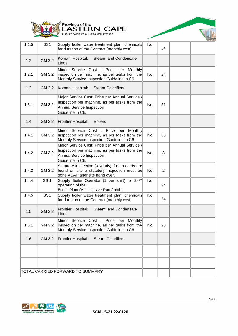
166
SCMU5-21/22-0120
1.1.5 SS1 Supply boiler water treatment plant chemicals for duration of the Contract (monthly cost)
No 24
1.2 GM 3.2 Komani Hospital: Steam and Condensate Lines
1.2.1 GM 3.2 Minor Service Cost : Price per Monthly inspection per machine, as per tasks from the Monthly Service Inspection Guideline in C6.
No 24
1.3 GM 3.2 Komani Hospital: Steam Calorifiers
1.3.1 GM 3.2
Major Service Cost: Price per Annual Service /
Inspection per machine, as per tasks from the
Annual Service Inspection
Guideline in C6.
No 51
1.4 GM 3.2 Frontier Hospital: Boilers
1.4.1 GM 3.2 Minor Service Cost : Price per Monthly Inspection per machine, as per tasks from the Monthly Service Inspection Guideline in C6.
No 33
1.4.2 GM 3.2
Major Service Cost: Price per Annual Service /
Inspection per machine, as per tasks from the
Annual Service Inspection
Guideline in C6.
No 3
1.4.3 GM 3.2 Statutory Inspection (3 yearly) If no records are found on site a statutory inspection must be done ASAP after site hand over.
No 2
1.4.4 SS 1 Supply Boiler Operator (1 per shift) for 24/7 operation of the
Boiler Plant (All-inclusive Rate/mnth)
No 24
1.4.5 SS1 Supply boiler water treatment plant chemicals for duration of the Contract (monthly cost)
No 24
1.5 GM 3.2 Frontier Hospital: Steam and Condensate Lines
1.5.1 GM 3.2 Minor Service Cost : Price per Monthly inspection per machine, as per tasks from the Monthly Service Inspection Guideline in C6.
No 20
1.6 GM 3.2 Frontier Hospital: Steam Calorifiers
TOTAL CARRIED FORWARD TO SUMMARY

167
SCMU5-21/22-0120
SCHEDULE 4 : REPAIRS SUBJECT TO APPROVAL
ITEM Nr.
PAYMENT REFERS
DESCRIPTION UNIT QTY RATE AMOUNT
1 GM 2.8
LABOUR RATES APPLICABLE TO UNSCHEDULED WORK: Labour rates that Contractor will charge for additional adhoc work that is not contained in Schedules 1 to 3.
1.1 Technician R/hr 520
1.2 Senior Artisan (Trade Tested & Additional Certification)
R/hr 1000
1.3 Artisan (Trade Tested) R/hr 770
1.4 Utility Man (Non-Trade Tested) R/hr 1580
1.5 Artisan Aid R/hr 880
1.6 General Worker R/hr 1750
2 GM 2.8.3
TRAVELLING : Travelling cost will be as per the rates for reimbursable expenses published monthly by the National Department of Public Works at the time of rendering the service/repair.
R/km
2.1 Vehicle Travelling Estimate R/km 180 000
3 GM 2.8.3
ACCOMMODATION AND SUBSISTENCE : Daily Rates per person that the Contractor will claim for approved trips lasting more than one day at a time.
3.1 Accommodation R/night 60
3.2 Subsistence R/day 60
4
GM 2.5
(10), GM
2.8.1 & GM
2.10.3
PROVISION TO COVER REPAIRS DURING THE TERM OF THE CONTRACT : Lump Sum Provision to cover repairs and breakdowns during the course of the Contract in addition to the agreed routine servicing of the Assets.
PSum 1 R6 500 000.00
R 6 500 000,00
5
GM 2.8.1 &
Clause
11.2(8)
DIRECT FEE PERCENTAGE (MARK-UP) ON MATERIALS AND SERVICES THAT IS NOT INCLUDED IN PRICE LISTS: Mark-up on proven cost for materials and/or Outsourced Services based on the Provisional sum listed in Item 4. above.
%
TOTAL CARRIED FORWARD TO SUMMARY
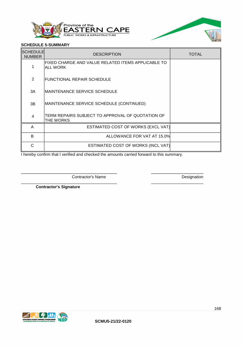
168
SCMU5-21/22-0120
SCHEDULE 5-SUMMARY
SCHEDULE NUMBER
DESCRIPTION TOTAL
1
2
3A
3B
4
FIXED CHARGE AND VALUE RELATED ITEMS APPLICABLE TO ALL WORK
FUNCTIONAL REPAIR SCHEDULE
MAINTENANCE SERVICE SCHEDULE
MAINTENANCE SERVICE SCHEDULE (CONTINUED)
TERM REPAIRS SUBJECT TO APPROVAL OF QUOTATION OF THE WORKS
A ESTIMATED COST OF WORKS (EXCL VAT)
B ALLOWANCE FOR VAT AT 15.0%
C ESTIMATED COST OF WORKS (INCL VAT)
I hereby confirm that I verified and checked the amounts carried forward to this summary.
Contractor's Name Designation
Contractor's Signature

169
SCMU5-21/22-0120
PART C3: SCOPE OF WORK
C3.1a Service Information – Standard Specification for Mechanical and Electrical Repairs
C3.1b Service Information – Supplementary Specification for Specific Asset Type
C3.2 Steam Boiler Daily Inspections
C3.3 Steam boiler –Weekly inspections
C3.4 Steam boiler –Monthly inspections
C3.5 Steam boiler –Annual inspections
C3.6 Steam boiler –Statutory inspections
C3.7 Steam calorifiers –weekly inspections
C3.8 Steam calorifiers –annual inspections
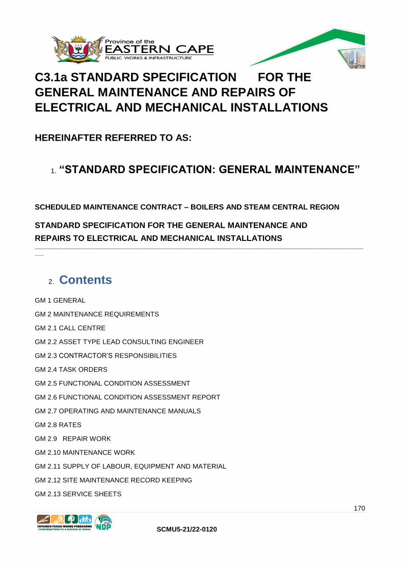
170
SCMU5-21/22-0120
C3.1a STANDARD SPECIFICATION FOR THE
GENERAL MAINTENANCE AND REPAIRS OF
ELECTRICAL AND MECHANICAL INSTALLATIONS
HEREINAFTER REFERRED TO AS:
1. “STANDARD SPECIFICATION: GENERAL MAINTENANCE”
SCHEDULED MAINTENANCE CONTRACT – BOILERS AND STEAM CENTRAL REGION
STANDARD SPECIFICATION FOR THE GENERAL MAINTENANCE AND
REPAIRS TO ELECTRICAL AND MECHANICAL INSTALLATIONS _____________________________________________________________________________________________________________
___
2. Contents
GM 1 GENERAL
GM 2 MAINTENANCE REQUIREMENTS
GM 2.1 CALL CENTRE
GM 2.2 ASSET TYPE LEAD CONSULTING ENGINEER
GM 2.3 CONTRACTOR’S RESPONSIBILITIES
GM 2.4 TASK ORDERS
GM 2.5 FUNCTIONAL CONDITION ASSESSMENT
GM 2.6 FUNCTIONAL CONDITION ASSESSMENT REPORT
GM 2.7 OPERATING AND MAINTENANCE MANUALS
GM 2.8 RATES
GM 2.9 REPAIR WORK
GM 2.10 MAINTENANCE WORK
GM 2.11 SUPPLY OF LABOUR, EQUIPMENT AND MATERIAL
GM 2.12 SITE MAINTENANCE RECORD KEEPING
GM 2.13 SERVICE SHEETS

171
SCMU5-21/22-0120
GM 2.14 VOLTAGE SURGES DUE TO LIGHTING AND OTHER CAUSES
GM 2.15 SHEQ: SAFETY, HEALTH, ENVIRONMENTAL AND QUALITY
GM 2.16 HIV / AIDS AWARENESS
GM 3 MAINTENANCE CONTROL PLAN
GM 3.1 WORK QUALITY
GM 3.2 PRELIMINARY MAINTENANCE CONTROL PLAN
GM 3.3 MAINTENANCE CONTROL PLAN
GM 4 COMMUNICATION
GM 5 PERFORMANCE MEASUREMENT
GM 6 SPECIAL TESTING OF AN INSTALLATION
GM 7 MAXIMUM MAINTENANCE DOWN-TIME
GM 8 MEASUREMENT AND PAYMENT

172
SCMU5-21/22-0120
STANDARD SPECIFICATION FOR THE GENERAL MAINTENANCE AND REPAIRS
OF
ELECTRICAL AND MECHANICAL INSTALLATIONS
3. GM 1 GENERAL
The successful Contractor will be responsible for, and is expected to, maintain all the plant and installations
detailed in the Price List and the Inventory of Equipment attached to this Contract.
The intention of this comprehensive maintenance Contract is to assess the current mechanical and/or
electrical condition of each asset, repair what is needed, and maintain all equipment included as part of
the Contract, in such a manner that, except for normal wear and tear, their condition don’t deteriorate
during the initial Service Period of 24 (twenty-four) months. This initial Service Period is extendable by up
to another 12 (twelve) months to give a total Contractual period of up to 36 (thirty-six) months. Any
potential extension will however be subject to the Contractor meeting the applicable quality and
performance requirements of this Contract during the first 24 (twenty-four) month period. Instruction to
proceed with any work related to this Contract shall be authorized by means of a Task Order from the
Service Manager.
As skills transfer are an integral part of this Contract the Employer’s Operating and Maintenance staff will
be responsible for all operating and daily inspections on the equipment, unless otherwise specified in the
relevant asset specific Supplementary Specification and/or Relevant Price List.
The Contractor is required to provide pricing for the following items in the Contract as expanded on in this
specification for each asset type and equipment quantity as covered by this Tender:
• Verify the Assets and update the Asset Inventory List that is provided with this Contract;
• Compile a Preliminary Maintenance Control Plan (Annexure I) to determine what routine
servicing should take place on each type of equipment covered by the Contract, and at
what frequency the services should take place during the Contract Period if this does
not correlate to the Price List service frequency proposed by the Service Manager. With
reference to the Price List and C3.1b Supplementary Specification requirements, the
Contractor must submit an all-inclusive price and quantity of, for each Service Activity
required. Service Activities may include Operations, Minor Services, Major Services or
Statutory Inspections as detailed in the Supplementary Specification related to this bid
as well as the Price List.
• Cost to do a full functionality test and condition assessment of all equipment and
installations included in the Contract (after Contract award), and provide a priced key
spare part pricelist for this equipment;
• Cost to provide a detailed Functional Condition Assessment Report based on the
findings from the functionality test and condition assessment process.
It is to be noted that the aim of the maintenance Contract is NOT to replace random components at the
beginning of the Contract in anticipation of a possible breakdown during the Service Period. Only known
defects shall be repaired once approved by the Service Manager. It is the Contractor’s responsibility to

173
SCMU5-21/22-0120
decide if he/she wants to visit each site and acquaint themselves with the actual condition of each
installation before submitting a Tender, or to rely on the information as contained in the Inventory of
Equipment that is attached to this
Contract.
On-site Tender briefing meetings per Tender will be limited to one at one Health Facility on the list
covered by the specific Tender, as directed by the Service Manager in the Tender Notice.
Maintenance of an installation shall be performed in accordance with the Boilers, Calorifiers and Steam Lines Specific Service Information which will include:
1. This Standard Specification for the General Maintenance and Repairs of Electrical and Mechanical Installations,
2. The Technical Specifications that may be applicable,
3. The Supplementary Specification for this Asset Type,
4. The Operating and Maintenance Manuals (where applicable) for this Asset Type,
5. Relevant Inspection Check sheets for this Asset Type,
6. The Maintenance Control Plan per Health Facility,
7. All relevant SANS Standards and Legislation that is referred to in the above listed documents, and
8. All relevant drawings forming part of this Contract.
The main mechanical and electrical sections of a facility with their subsections as set out
in the Service Information and in the Price List will each be deemed "an installation".
Maintenance, as specified, will be applicable to all these installations.
All Contractors are to undergo an approximately three-hour long Contractor’s induction process before being allowed to work at any of the sites. This induction shall cover the General Rules for Contractors on Site, the penalty system applicable to this Contract, as well as the minimum work quality standards for the work to be done on site.
Major equipment replacement, major upgrades and/or redesigned functionality will be
handled outside of this Contract via a separate projects program, and are therefore not
part of this Contract. The maintenance and repair work phase will run parallel to each
other at the same time.
GM 2
MAINTENANCE REQUIREMENTS
i. The Contractor will adhere to the Task Order and when completed, contact the
Service Manager for formal approval and signing off, of the Task Order. The
Engineering Representative will assist the Service Manager in verifying completed
work.
ii. The Contractor is expected to be fully aware of his obligations in so far as this
Contract is concerned and he shall attend to the maintenance procedure within the
time limits specified for each class of maintenance procedure.

174
SCMU5-21/22-0120
iii. The completed Task Order will be returned to the Service Manager, who will forward
it to the Call Centre to log the completed Task Order into the system. When the
completed Task Order is logged into the system the job will be closed.
iv. When a maintenance procedure cannot be completed within the specified downtime
the Contractor should apply in writing to the Service Manager for an extension of
time with reasons for the delay. This application should be submitted as soon as
the details of the maintenance procedure and availability of spare parts are known.
v. The Call Centre Manager will submit a weekly response performance report to the
Service Manager, who will make a decision on the implementation of penalties which
will depend on the nature of each breakdown, as well as valid claims on delays
received from the Contractor. The recorded report date and time as well as the
recorded completion date and time will be regarded as sufficient and final proof for
the proper administration of this aspect of the Contract.
4. GM 2.2 SERVICE MANAGER
A Sakhiwo FM Consortium Representative will be appointed as Service Manager (Project Manager) to
manage and administrate all work and financial aspects related to this particular bid. He/she will be supported
on the ground by an Engineering Representative to verify workmanship and compliance of completed
activities to Contract requirements. The Service Manager will be responsible for the following:
1. Perform duties as per the NEC3 Term Services Contract Standard Clauses;
2. Ensure that either he/she, or the Facility Specific Site Representative, visit the Facility
and compile reports on the status of the Facility infrastructure that forms part of this bid;
3. Liaise with the Call Centre and check on call outs;
4. Determine routine maintenance work to be done, and issue Task Orders for routine
maintenance and repairs/refurbishment/upgrades (that was accepted by the Employer),
to the relevant Contractor;
5. Consult and co-ordinate with the Program Lead Consulting Engineer as needed on
specific maintenance aspects, designs and specifications to be done;
6. Assess the completed work for the assessment period, consider the payment applications
lodged by the Contractor during this period, Certify the payment due, and issue a
Payment Certificate for the accepted work as per the Standard Contract clauses;
7. Monitor the logging of regular maintenance work done;
8. Prepare reports on maintenance and repair work done;
9. Liaise with the hospital Site Representative regarding all work to be done on this asset
type at the facility;
10. Liaise with management of the facility;
11. Obtain approvals from the Employer where required for .

175
SCMU5-21/22-0120
GM 2.3
CONTRACTOR’S RESPONSIBILITIES
The Contractor shall maintain the complete installation as specified in the Service Information for the full Contract period subject to the agreed repairs and performance criteria.
Maintenance implies and shall include routine preventative maintenance on a schedule as approved by the Service Manager, corrective maintenance, as well as breakdown maintenance of all components of the specified installation.
The Contractor shall be responsible to perform all tasks as specified in this specification, subject to the requirements of the NEC3 Term Service Contract Standard Clauses. In addition, the Contractor must:
1. Record work done, performance indicators, defects identified and/or corrected, and spares used;
2. Obtain work done sign-off on site as well as from the Engineering Representative;
3. Submit completed Task Orders and invoices to the Service Manager;
4. Attend scheduled project meetings with the Service Manager.
The Contractor shall, as part of his maintenance responsibilities repair or replace faulty
equipment upon logging of a breakdown, within the down-time as defined in Paragraph GM 7,
and against the Tendered rates as provided for in the Price List, and within the down-time as
specified in the applicable Task Order. In the event of any repair item for which a rate is not
available in the Price List, the rate as specified in the Task Order will apply.
GM 2.4
TASK ORDERS
All works required to be done by the Contractor will be instructed by issuing of a Task Order by
the Service Manager. No Works shall be conducted without a Task Order.
The Call Centre may issue breakdown and defects correction/repair Task Orders to the
Contractor at any time during the Service Period, but they must all be copied to the Service
Manager. The time for the completion of the Breakdown Task Order will be as per the
allowable response times in Table 1 in Section GM 7.
If the exact nature and possible cost of rectifying a breakdown is not known when the Breakdown Task Order
is issued to the Contractor, the task order will be issued with provisional information and costs estimates. The
Contractor shall respond to such a Breakdown Task Order by traveling to the site to evaluate the breakdown
(scope of repair work), estimate the realistic cost as well as downtime and provide feedback to the Service
Manager to form the basis of the revised Task Order.
Should the Contractor not be able to complete the Breakdown Task Order within the agreed and approved
time for completion, it shall be the Contractor’s responsibility to obtain an extension of time from the Call
Centre Manager. The written report shall clearly state the reasons for requiring the extension, as well as the
actual extension period required.

176
SCMU5-21/22-0120
Should the actual time for completion of the Breakdown Task Order exceed the agreed time allowed,
including any extension of time, the Contractor shall be liable for damages at the rate stated in the Task
Order.
The Service Manager will issue Task Orders for the routine maintenance services, and
approved repair/upgrade work once the Maintenance Control Plan has been approved and updated with the
relevant information from the Repair Schedule as per GM 3.
Routine maintenance, approved repairs and breakdown repairs will all be done parallel to each other on the
equipment as per the Maintenance Control Plan and Call Centre priorities.
5. GM 2.5 FUNCTIONAL CONDITION ASSESSMENT
Immediately after handing over of the site, and having attended the Contractor’s Induction Training Session,
the Contractor shall start with a detailed functional test and condition assessment process of the
specified installation/equipment at each Health Facility and submit a detailed report to the Service Manager
regarding the functionality, performance and condition of the equipment. It is this Contract’s intention that
this task be completed within two weeks of each site handover to the Contractor, but the Service Manager
will arrange and agree specific deliverable dates for each Health Facility with the Contractor in this regard as
part of the Contractor’s Maintenance Control Plan.
The following work shall be carried out during the time allowed for the execution of the Functional Condition
Assessment:
1. Verify the Asset Data from the Asset Inventory List in C4.1, obtain the additional
asset information that might be required for a specific piece of equipment, and update
the Inventory of Mechanical and Electrical Equipment for each Health Facility with
make and model numbers, capacities and general condition, year of manufacture
(age), additional equipment to be added to the list, and equipment to be deleted from
the list (i.e. equipment not on site anymore), etc., as per the fields provided in the
format provided by the Service Manager after Contract award.
2. Prepare a clear A4 size line drawing of the building/ward/room in which the plant
is installed, typically as per one of the two examples below, and show positions of
the equipment schematically on this drawing. Please provide basic information
regarding the general condition of the room/facility/building where the asset is located
(this will assist to provide information to the facility repair teams), next to, or below
the line drawing;

177
SCMU5-21/22-0120
One line drawing per location per Health Facility must be provided and can be hand
drawn, provided that the drawing is clear, neat and all info is readable. Where applicable the position of the
equipment on the walls must be shown (i.e. Split Air Conditioner Units).
3. Record the number/name of each piece of equipment on the line drawing. If no
name/number exists on the equipment itself, allocate a descriptive number (i.e. Fire
Pump 1) and mark this on the equipment with a black permanent marker pen.
Reference shall be made to this ID number in the defects listed in the Repair
Schedules for each item of equipment to identify the equipment accurately.
4. Verify what spare parts (if any) are available on site for the equipment covered by
the Contract, as well as the condition there-off;
5. Compile a Priced Spare Part List, (based on the Contractor’s cost price for the
spares) for the relevant spare parts required for a repair of all the types of equipment
listed in the Asset Inventory, and indicate on this list what spares should be kept in
stock on site for use by the site maintenance staff. The Employer however retains
the right to negotiate the offered spare part prices with like type spares prices
solicited through the Tender process, if they are not in line with national price norms.
6. Inspect the condition and test the functionality of all components of the
installation to confirm the extent of the repair work required (if any). If the equipment
is not in an operable state record this and proceed with item 7 below;
7. Verify if the equipment meets current standard technical specifications for the
specific application (for example: a split system air conditioner may be functionally
good and serviceable, but does not meet the criteria to operate inside an operating
theatre or infection control area). Advise on an alternative if applicable. Please
consult the Facility Manager when doing the assessment to get information regarding
any issues that they are experiencing with the equipment.
Generator Set 1
Generator Set 2
Generator Set 1
Generator Set 2
178
SCMU5-21/22-0120
8. Verify the estimated remaining service life for the equipment based on the
equipment’s age and current condition. If the equipment is old and in a bad state it
might be more cost effective to replace the unit rather than rebuilding it. Please
advise in this regard;
9. Should it be impossible to determine the details of the defect without dismantling the
machine/equipment item, the Contractor shall nevertheless prepare an estimate with
a cost breakdown for repairs he/she anticipates will be needed. After a written
instruction has been received to repair the machine/equipment item, the final cost
will be determined after the machine/equipment item has been dismantled for repairs.
Equipment shall not be dismantled for inspections during the equipment
functional condition assessment period.
10. Compile a detailed Repair Schedule for each separate equipment unit
(machine). This Repair Schedule will consist out of a clear identification of the
equipment unit, a detailed description of what is wrong with the equipment unit, a
detailed repair or replacement method statement (and explanation on why it is
recommended that the unit be replaced if applicable), and an accurate detailed
quote, with estimated lead times and a high-level project plan to enable the work to
proceed if the approval to do so is granted by the Service Manager via a Task Order.
(See GM 2.8 for the rates requirements)
11. The Employer does not guarantee that any, or all, of the repairs/replacements
recommended via the repair schedules, will be accepted for implementation by the
Contractor. Accepted Repair Schedules will however become part of the Final
Maintenance Control Plan once approved by the Employer, and will then be included
in the work scheduled for this Contract. Depending on the cost and complexity,
equipment replacement recommendations might be transferred to the Repair Project
Work Stream of the Employer’s Mechanical and Electrical Equipment Repair
Programme.
12. Compare the identified defects of each item of equipment with the components
already included under the standard minor and major services scopes in the
Contract Price List, and remove costing for these from the repair requirements.
Include all identified defects into the Functional Condition Assessment Report, but
only price the defects not covered by the standard servicing scope of works. (See
GM 3.2 (3) for costing of the standard services)
13. Where applicable, obtain copies of Statutory Inspection and Test Reports from
the Health Facility (if available) and attach these to the Defects Inspection Report.
14. Submit the detailed Functional Condition Assessment Report to the Services
Manager who shall thereafter demarcate any areas to be repaired and forward this
information to the Contractor. Once approval is granted, the Service Manager will
instruct the Contractor about the repair work to be done.
6. GM 2.6 FUNCTIONAL CONDITION ASSESSMENT REPORT
A Functional Condition Assessment Report must be compiled for each Health Facility, and shall contain the
following:

179
SCMU5-21/22-0120
1. The updated Asset Inventory List (both hard and electronic copies) completed in the
Excel Format provided by the Service Manager after Contract Award;
2. Clear location identifiable layout line drawings of the equipment, with ID numbers and
brief room/facility/building condition description as per GM 2.5 (2)
3. A list of spare parts, and their condition, that is currently available on site;
4. A priced spare part list of the typical spare parts that might be needed to do repairs on
the equipment if it should breakdown or fail. The Contractor must also indicate on this
spare part price list which consumable spare parts (i.e. fan belts, filters, oil, fuses, light
globes, etc.) that can be replaced by the site maintenance staff, should be kept in stock
at the Health Facility;
5. A summary of the equipment per Health Facility indicating:
• Condition;
• If the equipment meets current technical specifications;
• Estimated remaining Service life before replacement will be due; and
• Recommended work to be done (i.e. service only, minor repairs required, major
repairs required, replacement or upgrade recommended).
6. A Repair Schedule for each repair that is required. This information will be used to
populate the Task Orders for accepted repairs, or feed the Tender document information
in case it is moved to the Project Work Stream;
7. A description of the defect for which repair work is not easily identifiable with an estimate
of the final cost for repairs. This item will typically apply to breakdowns or defects where
the machine or equipment must be de-commissioned and at least partially dismantled
before the extent of the work can be fully established;
8. Compile a list of equipment for which a Statutory Inspection and Test is, or will become
due during the Contract period. Copies of previous Inspection and Test Certificates to
be attached to the report (if available).
Should the Contractor not be able to complete the Functional Condition Assessment Report within the period
as specified GM 2.5, it shall be his responsibility to obtain extension of the Functional Condition Assessment
period from the Service Manager. The written report shall clearly state the reasons for the extension, as well
as the actual extension required. An extension of time shall only be considered by the Service Manager if
the Engineering Representative believes the Contractor has carried out the already completed portion of the
report with the due diligence and attention to detail.
Should the actual time for the completion of the report exceed the specified time for completion, including
any extension granted, the Contractor shall be liable to a payment reduction for the difference between actual
and approved completion periods. The value of the payment reduction for each health facility shall be as
specified in Section X18 of the Secondary Options Clauses of the Contract.
After the repair phase work and costs have been accepted, the Contractor shall commence with the known
and approved repair work only after site access for repair work has been approved and the Task Order
issued. The Contractor shall complete the work within the period allowed for the repair work as specified in
the applicable Task Order.

180
SCMU5-21/22-0120
7. GM 2.7. OPERATING AND MAINTENANCE MANUALS
The Contractor shall, where specified, and as part of the repairs to each installation, compile and submit a
comprehensive Operating and Maintenance Manual based on the Original Equipment Manufacturer’s
requirements. The Contractor shall ensure through training that the operating and maintenance personnel of
the Health Facility are conversant with the instructions as presented in the Operating and Maintenance
Manual, as per SS 8 and SS 9.
The Operating and Maintenance Manual, as accepted by the Service Manager, shall be used as a basis for
preventative maintenance. The Contractor shall perform all preventative and corrective maintenance as
described in the Operating and Maintenance Manual. This shall be in accordance with the Standard and
Supplementary Specifications.
The Operating and Maintenance manuals must be based on the updated Inventory of Equipment (C4.1) data
after completion of the Functional Condition Assessment, and shall be updated with respect to Make, Model
Number, Capacity and any other relevant data.
The Contractor must provide three (3) sets of each required Operating and Maintenance Manual as follows:
• One set to be installed at a suitable position on a short chain, against a wall in the
room/area where the equipment is located, or as otherwise instructed by the Service
Manager for outside and spread out equipment;
• Two sets to the Services Manager.
The Operating and Maintenance Manuals must be delivered as soon as possible after the Functional
Condition Assessment Report has been completed. Also see Section GM 3.3 (15).
Where several of the same equipment is in the same room/area, only one set of three Operating and
Maintenance Manuals is required. If the same equipment is spread out throughout the health facility the
Contractor must install one Operating and Maintenance Manual near each one, or group of the equipment
unless otherwise instructed by the Service Manager. This does not apply to equipment like split air
conditioners, etc. for which only one set of three Operating and Maintenance Manuals per make and model
will be required. The Service manager will instruct the Contractor where to install the chained Operating and
Maintenance Manual for equipment like air conditioners.

181
SCMU5-21/22-0120
The Contractor will be required to install several Document Consoles (storage and writing platform units)
with sleeve anchors or bolts, into the walls at different locations of each Health Facility, to secure and store
the chained manuals and maintenance logs. A Provisional sum will be included for this in the Price List.
8. GM 2.8. RATES
Scheduled work is all planned routine servicing of the equipment at the all-inclusive Contracted Rates
contained in Schedule 3 of the Contract. Unscheduled work is all repairs, breakdowns, special maintenance
activities, special tests and/or replacement tasks, that is ordered via a Task Order by the Service Manager,
in addition to the scheduled work. Payment for this work will be based on the Contracted Rates from
Schedule 4.
Where no rates exist in the Contract, the itemized breakdown shall be accompanied by documentary proof
from the Supplier, Manufacturer, Engineering Works, etc., where materials were bought or services out-
sourced from. The Employer however retains the right to verify and test these rates against the market.
The Contractor shall submit quotes for all Unscheduled work with an itemized breakdown of the total cost
involved for acceptance by the Service Manager, in a quotation as detailed below:
GM 2.8.1
Materials and Outsourced Services
Unscheduled:
List all items with quantities and rates as per quotations or
price lists obtained from suppliers or service providers
(proven reasonable cost), and attach a copy of the
quotation/price list to the quotation. Apply the Direct Fee
Percentage (Mark-up %) to all proven reasonable material
costs and outsourced services.
Direct Fee % (Mark-up %): Mark up percentage on proven cost to cover P’s & G’s, overheads, profit, etc. as per Schedule 4 based on NEC3 TSC Contract Data.
Scheduled: All materials required for Scheduled Servicing are included
into the pricing for the Service as per Schedule 3.
GM 2.8.2
Labour
Unscheduled:
List time required for travelling to and back from site (subject
to conditions contained in GM 2.8.3 below), actual repair
and/or replacement, testing and commissioning time of all
unscheduled items at the applicable labour rates as stated
in Schedule 4. No Direct Fee % will be applicable to
Contracted labour rates.
Scheduled:
Cost is included in Service costs as per Schedule 3.
GM 2.8.3
Transport and Accommodation

182
SCMU5-21/22-0120
Unscheduled: Traveling and Accommodation claims will be subject to the condition contained in GM 2.8.4
below. Travelling cost will be as per the rates for reimbursable expenses published monthly by the National
Department of Public Works applicable at the time of rendering the service/repair.
Allow for the actual distance traveled (and specify the reason for the traveling). All travel time and
disbursements need to be supported by a Google Maps route planner printout for proof of travelling distance
and time. Kilometer claims can be claimed from point of departure to destination and back, but must be
linked to the indicated kilometers as per the Google Map attached and referenced to. The Contractor must
submit proof of registration to verify the engine cubic capacity of the vehicle, in respect of any vehicle to be
claimed for. Allow for the actual accommodation and disbursements (and specify the reason for the
accommodation requirement) at the rates as per Schedule 4. Trips must be combined with Scheduled
Servicing trips where possible, to minimize additional expenditure. Trips will be in accordance with
the approved Maintenance Control Plan.
GM 2.8.4
The Employer requires that the Contractor be based in a location inside the Cluster
or District Area that the Contract is awarded for. The home base (departure point) must
therefore be located inside the Cluster Area. If the Contractor does not have a home base
in the Cluster Area, the traveling rates (for both distance and labour) will be calculated
based on a location inside the Cluster which will typically be the largest Town or City located
inside the Cluster or District, as may be applicable as instructed by the Service Manager.
GM 2.8.5
Provisional Sums
It is the Employer’s sole discretion to decide on spending any, all or none of the Provisional Amounts listed
in the different Price List Schedules of this Contract.
GM 2.9 REPAIR WORK
GM 2.9.1 Definitions
1. Defect
For this maintenance Contract, a defect shall mean a deficiency in any component of an installation which
impairs the functionality of that component or equipment. Worn parts of a component which do not impair
the functionality and/or performance of the component will not be regarded as a defect.
Defects may be classified in the following three groups:
(i) Type A defect
Those deficiencies which can be rectified by proper maintenance only, i.e. set parameters of a control
system, proper lubrication, balancing, alignment, set pressures on safety valves, cleaning and de-staining,
etc.
(ii)Type B defect

183
SCMU5-21/22-0120
Those deficiencies which can only be rectified by replacing parts of, or the complete component as in the
case of a breakdown or where a certain amount of upgrading is necessary such as the provision of anti-
vibration mountings, removal of rust and re-painting, etc.
(iii)Type C defect
Those deficiencies which are visible but which do not impair on the functionality of the installation or system
yet, such as structural cracks in parts of a component, rust, bad workmanship during a previous Contract,
etc.
Components in which abnormal noise and/or vibration is present shall be serviced in accordance with the
Manufacturer’s recommendations and if the noise and/or vibration persists, the deficiency will be classified
as a defect.
2. Repairs
Repairs of an installation shall mean the elimination of the deficiencies classified as types B and C defects
in Paragraph (1.) above.
The specific repair phase commences as indicated on the Task Order issued by the Service Manager for
each approved repair. The repairs must be completed within the period as determined by the Task
Completion Date as stated in the Task Order. Delay damages for late completion will be applicable as
indicated on the Task Order.
Depending on the nature of the work and availability of funds access may be given at any time during
the Service Period and not necessarily directly after site hand-over.
A representative of the user department or person in charge of the plant, system or building shall endorse
the schedule after completion of the maintenance or servicing procedure to the effect that the maintenance
or service is, to his opinion, completed satisfactorily and shall countersign the service schedule. Where
necessary the Site Representative will inspect the work done and report his findings to the Service Manager.
GM 2.9.2 Scope of Repair Work
The repair work shall be completed within the time allowed for repairs for each installation as defined in the
applicable Task Order. If the work is to be carried over two or more financial years the work will be
segmented and prioritized according to the Final Maintenance Plan. The Contractor will be informed of the
work to be completed within each financial year. The starting date for repair work for the current
financial year will be the date of acceptance of the measured Price List from the Functional Condition
Assessment Report. The starting dates for subsequent years will be on 1 April of that particular year.
All repair work shall be executed using resources (labour, equipment materials and spare parts) that comply
with the requirements of GM 2.11.
The said repair work shall be executed in accordance with the relevant codes of practice, standards,
regulations, municipal laws and by-laws, manufacturers’ specifications and codes of practice included in this
specification.
184
SCMU5-21/22-0120
GM 2.10 MAINTENANCE WORK
Maintenance work commences with the acceptance of the Tender bid and expires at the end of the Service
Period. As compensation, the Contractor is paid the remeasured Contracted quantities, distributed in
agreed intervals and amounts over the Service Period as per the Final Maintenance Control Plan, at the rate
Contracted for the applicable maintenance work, subject to the requirements of GM 8.
GM 2.10.1
Routine Preventative Maintenance
This entails the rendering of services and servicing of equipment according to a predetermined Maintenance Control Plan to:
1. Repair, lubricate, clean and service components of equipment, units or parts thereof for each installation at pre-scheduled intervals regardless of condition;
2. Re-adjust, reset, clean, balance, corrosion protect all components of equipment, units or parts thereof for each installation, and
3. Carry out all necessary and implied actions to maintain installations in a functional condition (i.e. replace or clean filters, replace or top up fluids, etc.)
Preventative maintenance shall be aimed at prevention or at least minimization of
breakdowns.

185
SCMU5-21/22-0120
GM 2.10.2
Corrective Maintenance
This entails regular observation of the equipment, identifying impending breakdowns, maladjustment or anomalies of equipment, units or parts of installations and subsequent action to restore installations to a fully functional condition before a breakdown occurs.
The Maintenance Procedures for Corrective Maintenance shall be compiled by the Contractor and is included in the Maintenance Control Plan for each system or plant. Inspection items shall include, inter alia, the following:
Checking for:
1. Unusual noise and vibration;
2. Abnormal surface temperature of machines such as electric motors;
3. High temperatures of equipment and wiring inside switchboards;
4. Incorrect settings or operation of safety devices;
5. Alarm conditions of any instrument or control panel;
6. Gas or fluid leaks from the equipment or associated piping systems.
The frequency of corrective maintenance shall be determined by the Contractor himself in
line with the recommendations from the Operating and Maintenance Manuals, and actual
operational environment where the equipment is operating. This may vary from once
every day for high-risk, sensitive installations to once a month for low-risk installations such
as exhaust fans and office air conditioners. The frequency of corrective maintenance must
be accepted by the Service Manager in the Maintenance Control Plan.
GM 2.10.3
Breakdown Maintenance
This entails repair and/or replacement of defective equipment, units or parts of installations following a
breakdown that leaves the installation inoperable or unsafe, and subsequent action to restore the installation
to their normal functional condition, within the maximum down-time allowed.
Breakdown repairs will be controlled via the Call Centre and approved Breakdown Repair Task Order
process as per GM 2.1. A provisional amount will be included in the Contract Price List Schedules to cover
Break Down Task Order expenditure.
9. GM 2.10.4 Commencement of Service Period
The Contractor shall accept full maintenance responsibilities for each installation from the date on which the
site has been handed over to the Contractor. An annual maintenance service shall be carried out on all
installations during the period in which the Defects Inspection Report is compiled, or as soon as
possible thereafter. If the current statutory compliance of a qualifying asset cannot be verified with the
correct documentation of proof, a statutory inspection must be performed immediately after the first annual
service has been completed.
For equipment or installations where the complete installation is shut down for the repair phase, no
maintenance services will be required during the repair period.

186
SCMU5-21/22-0120
GM 2.11 SUPPLY OF LABOUR, EQUIPMENT AND MATERIAL
1. Labour
Only competent, qualified personnel shall be allowed to execute all maintenance work.
2. Equipment
All tools, equipment and consumables required for performing maintenance work shall be supplied by the
Contractor at his own cost (except where otherwise agreed to in writing and provided by the Employer). The
Contractor may use already installed Employer equipment such as crawl beams and crawls, etc. provided
that they obtain written approval from the site Maintenance/Technical Manager to do so. Such site approval
will be based on the serviceability of the equipment, and upon confirmation of the Contractor’s competency
compliance in being able to use and operate this equipment during maintenance.
3. Materials and Parts
All materials, spare parts, components, equipment and appurtenances necessary for the complete
maintenance of each installation shall be supplied and installed by the Contractor at the rates and
quantities as instructed by the Service Manager, after the Functional Condition Assessment Report as
specified in GM 2.5 has been accepted.
Only original parts as specified by the Original Equipment Manufacturer may be used for replacement
purposes. Generic or alternative parts will only be allowed if they comply fully with all the specifications of
the original parts, but may only be used upon written acceptance by the Service Manager.
Substitute electronic components will be acceptable, PROVIDED that they are equal to, and of the same
quality as, or superior to, the original components and are accepted, in writing, by the Service Manager.
All parts, spares and materials which are used, shall conform to the applicable SANS Specifications and
shall, where possible, carry the SANS mark of approval.
Substitute parts, as well as the serial numbers (where available) of the original and new components, shall
be entered on the service sheets and in the maintenance/repair log-book.
The Contractor shall obtain, and cede any supplier’s or factory guarantee of repaired or replaced
components to the Employer. All workmanship, new equipment, materials, components, systems, etc. used
for servicing and repairs shall be guaranteed for 12 months unless otherwise agreed to in writing with the
Service Manager. The guarantee cards for repaired or replaced components or equipment shall also be
attached to service sheets and the maintenance/repair log-book. New equipment and system installations
will in addition to the above requirements also have a twelve (12) month defects liability period, valid from
the date of successful commissioning and hand over to the Employer as acceptance by the Service Manager.
All scrapped and/or removed parts and equipment that might be installed elsewhere, or that will not be
returned to service again, must remain on site after removal or disassembly of the equipment as they
remain the property of the Employer. The Maintenance/Technical Manager of the facility will indicate to the
Contractor where to place these items after removal. Removal of any parts and/or equipment for
whatever reason from site, may only occur with the written approval to do so by the Maintenance/Technical
Manager subject to the rules and regulations that the Employer has in this regard.

187
SCMU5-21/22-0120
2. GM 2.12 SITE MAINTENANCE RECORD KEEPING
The Contractor shall provide and maintain hard-cover A4 size maintenance files for each installation for the
duration of the Service Period. Copies of all schedules, checklists, breakdown reports, preventative
maintenance records, component replacement records, service sheets, etc. shall be filed in these.
An A4 size register book shall be kept for all work performed on the equipment, to state the service
technician’s name, surname, date of work performed, and a short description of the work performed. This
book must be installed on a short chain next to the relevant Operating and Maintenance Manual as per GM
2.7.
Copies of the site maintenance records and all service sheets, shall be submitted to the Service Manager at
each monthly meeting, while copies of the service sheets must also accompany all claims and invoices.
Statutory Logbooks must be supplied and maintained on site for all statutory equipment such as pressure
vessels, boilers and lifts.
3. GM 2.13 SERVICE SHEETS
Every service, repair, test, inspection, etc. related to the maintenance portion of the Contract, shall be fully
described on a service sheet which must be completed and signed by the Contractor and attached to the
Task Order when it is returned to the Service Manager. The following minimum information shall appear on
service sheets:
1. The company name and address;
2. A unique work sheet serial number;
3. The corresponding Task Order unique number;
4. The district and health facility names;
5. The building/area name or alternatively the building/area code;
6. The plant identity code and description;
7. The nature of the call, i.e. P1, P2, P3 or P4 (see GM 7);
8. A general description of the problem or purpose of the work to be done, alternatively
the complaint as received by the Call Centre;
9. A statement as to whether the individual system is operational or not in terms of the
specification;
10. Should the system not be operational (in case of a breakdown) the response time
and repair time shall be recorded individually and details of a preliminary service
sheet shall be forwarded to the Call Centre Manager;

188
SCMU5-21/22-0120
11. The description of the repairs/replacements carried out on each machine/equipment
item on that specific system;
12. A list of materials used for each machine/component. Where scheduled items are
used, only the description can be listed. For non-scheduled items, a copy of the
quotation must be attached to the service sheet;
13. A detailed report on the extent of the work done together with the total cost involved;
14. Suggestions to avoid similar future problems;
15. A list of the Contractor's personnel responsible for the work with the date, starting
time, completion time, distance traveled, and any accommodation and S&T costs;
16. Signature and name of the responsible Employer site technician/artisan/engineer
and the Site Representative, confirming the work was completed to the required
quality and performance standards, and that the equipment is operational again;
17. Signature and telephone number of the User of the equipment or the person who
initiated a call or Task Order (if it was a defect, or breakdown).
Service sheets shall also be used for normal routine maintenance services and other non-maintenance
activities such as training of the health facility’s operating and maintenance personnel and administration
duties of heads of firms when managing the Contract.
The Service sheets shall be completed in three categories as follows:
1. For repairs on machines: The same data as above must be captured with one
service sheet to be completed for each repair (See below for grouping of like type
equipment for servicing).
2. For normal maintenance on an installation: The same data as above must be
captured with one service sheet to be completed for each service (See below for
grouping of like type equipment for servicing).
3. For Administration and Training: In this case only the name of the Head of the
Company is required on the service sheet with no other reference to Building- or
Plant codes or machine ID numbers. A full description of the service provided must
be included.
Copies of the completed Service Sheet and Task Orders must be attached to all invoices and shall be
submitted to the Service Manager for discussions and acceptance.
An example of the Service Sheet is attached to the Contract Documentation as C7.
The standard requirement for normal services carried out on a specific plant is to complete one service sheet
for all the equipment within any one building. This standard requirement applies to installations where all
such machines can be serviced within a period of approximately five working days, but all equipment serviced
must be listed on the service sheet.

189
SCMU5-21/22-0120
For larger installations where the time required for a maintenance service is more than five working days,
the machines may be grouped together to form several groups within the building with the provision that
each group can be serviced within a period of approximately five working days. One service sheet shall be
completed for each group in a building, but all equipment included in the group must be listed on the service
sheet.
For smaller installations where the complete installation inside a building can be serviced in less than one
working day, the installations in more than one building may be grouped together, but all the equipment
covered by the service sheet must be listed.
The definition of the groups must be determined by the Contractor and clearly specified in the Maintenance
Control Plan for acceptance by the Service Manager.
4. GM 2.14 VOLTAGE SURGES DUE TO LIGHTING AND OTHER CAUSES
The area in which most of the sites are situated is known for heavy lightning storms. Damage caused by
voltage surges due to lightning, phase imbalance, low and high voltages, power failures, etc. will be dealt
with in the same manner as any other breakdown. Contractors are advised to investigate available surge
protection systems, if any, on each plant during the Functional Condition Assessment stage, and to decide
for themselves whether additional protection will be required or not.
The provision of additional surge protection systems shall form part of the repair activities, if accepted by
the Service Manager, and the cost thereof must be allowed for in the Functional Condition Assessment
Report.
Contractors may as an alternative provide and install one or more Universal Disturbance Analyzers to record
any voltage surges at their own cost. Breakdowns caused by voltage surges which can be proved beyond
any doubt will be dealt with in the same manner as operational damage and other normal breakdowns.
5. GM 2.15 SHEQ: SAFETY, HEALTH, ENVIRONMENTAL AND QUALITY
The Contractor must comply with all the Safety, Health, Environmental and Quality requirements as per C3.2
and GM 3.1, and must provide pricing to cover all the applicable requirements under this specification. The
Contractor must take note of any specific Safety, Health and/or Environmental risks that might be highlighted
in section SS 13.
6. GM 2.16 HIV / AIDS AWARENESS
The Contractor must comply with all the requirements as per C3.3, and must provide pricing to cover all the
applicable requirements under this specification.
24 M 3 MAINTENANCE CONTROL PLAN
The Contractor is responsible to compile a detailed Preliminary Maintenance Control Plan (Annexure I) as
per GM 3.2 which he need to submit with his Tender Bid. This plan must contain the details of what

190
SCMU5-21/22-0120
maintenance will be done (itemised), how often, what resources will be involved, what spares and
consumables will be used, how long it will take to perform the work, and the cost breakdown per service for
a specific Asset Type. The Service Manager gave service interval recommendations in Schedule 3, but the
Contractor can recommend alternative intervals for consideration and approval by the Service Manager.
After Contract Award the Contractor will be required to expand the Preliminary Maintenance Control Plan to
a Health Facility specific plan for each asset type with the assistance of the Service Manager.
GM 3.1 WORK QUALITY
Maintenance quality control shall be the responsibility of the Contractor who shall introduce a Maintenance Control Plan to assist him in ensuring that all preventative, corrective and breakdown maintenance is performed as described in the Service Information. The Contractor will be responsible to correct any sub-standard work that is discovered after the Contractor has done his work. The rework will be for the Contractor’s own account and must be signed off by the Site Representative after completion.
If the Contractor fails to remedy any sub-standard work within the time frame stipulated by the Service Manager, the Service Manager may at his/her discretion appoint another Contractor to execute the repair work. In this case, the replacement Contractor will be paid with the funds that were earmarked for the first Contractor to do the work, and the first Contractor will not be paid for that specific work.
GM 3.2
PRELIMINARY MAINTENANCE CONTROL PLAN
A preliminary version of the Maintenance Control Plan, based on the Asset Inventory Data, must be submitted with the Contractor’s Tender bid. This plan is a high-level plan on what maintenance tasks the Contractor will be performing on all the equipment across all Health Facilities covered by the Contract and must be completed on the forms of Annexure I. The information from the Preliminary Maintenance Control Plan will be expanded into that of the final Maintenance Control Plan as specified in Section GM 3.3 below. Details contained in this preliminary Maintenance Control Plan shall include:
1. A Maintenance Schedule containing all the different tasks that will be performed on
all the equipment covered by this Contract, and captured on the Preliminary Annual
Equipment Maintenance Schedule Form contained in Annexure I.
2. A brief Capacity Statement where the Contractor describes his company’s capacity
and experience that will be applicable to this Contract. This must include a
description and location of his home base (workshop/home/bakkie based, number of
staff with qualifications and experience, what staff and/or Sub-Contractors will be
used to support on the Contract, available tools and/or specialized equipment,
transport capacity and where staff will be based, as well as capacity/ability to repair
defective equipment (i.e. overhauling a pump or compressor);
3. A detailed Maintenance Task Planning Sheet (See Annexure I) for each of the
Minor, Major, and other, service activities priced in the Price List. This Maintenance Task Planning Sheet
will describe the pricing and details of scheduled maintenance activities to be performed during services
conducted as per the recommendations of the Preliminary Annual Equipment Maintenance Schedule,

191
SCMU5-21/22-0120
and will also be used to populate the respective Task Order. These prices must be all inclusive and must
include all labour, service parts, lubricants and consumables, special equipment (if required),
accommodation (if applicable) and any travelling and subsistence costs, etc. that might be applicable to
do the service. The service price must indicate clearly if more than one piece of equipment will be
combined for servicing during a single trip to avoid double payment for Travel and Subsistence related
payments by the Employer.
4. The service methodology;
5. Preliminary grouping of equipment for maintenance purposes as per GM 2.13 (if
applicable);
6. A breakdown of which sub-Contractors will be used (as per T2.2c), and for what
activities, by the Contractor in rendering the services required by this Contract. All
Sub-Contractors must also be registered on the Treasury Central Supplier Database;
7. GM 3.3 MAINTENANCE CONTROL PLAN
One Maintenance Control Plan must be compiled for each Health Facility covered by the
Contract. The Maintenance Control Plan shall be based on the Contractor's Preliminary Maintenance
Control Plan information, and updated with the findings and data from the Functional Condition Assessment
process. The Maintenance Control Plan shall be bound in a neat, A4 sized, ring bound document with a
cover page and back cover and an original copy presented to the Service Manager. The contents of the
document shall be indexed.
The Maintenance Control Plan will become the main plan for all work to be done under this Contract, as per
the Main Contract Clauses, after the Contract has been awarded.
When the documents are compiled, the Contractor may reproduce relevant paragraphs from any of the
specifications forming part of the Contract documents, or Operating and Maintenance Manuals, but should
there be any discrepancies between such paragraphs and paragraphs in the Maintenance Control Plan and
those in the Contract documents, those in the Contract documents shall be regarded as being correct and
shall apply.
The Maintenance Control Plan shall also contain the following in addition to the items listed in Section GM
3.2:
1. Detailed Maintenance Schedule per equipment type, per Health Facility on the
Annual Equipment Maintenance Schedule Asset Specific Form;
2. Remeasured service quantities for the routine services of Schedule 3 in the Price
List, based on actual equipment condition and the ability to perform a service on
them or not in their current condition. The Contractual payments will be based
on these remeasured quantities, accepted by the Service Manager, and not on
the original Tendered quantities which might have been based on incorrect
information at the time;
3. A risk register containing all the foreseen risks that can have an impact on the cost
and/or deliverables of this Contract as per the NEC3 Term Service Contract
Standard Contract Clauses numbers 11.2(14), 16.1, and 16.4;

192
SCMU5-21/22-0120
4. A summary of the repair and maintenance work to be carried out in terms of the
Contract giving details of the conditions of the various installations at the facility
affected by the activities under the Contract.
5. Details of how the Contractor intends to carry out the various types of maintenance
work especially breakdown maintenance should breakdowns occur.
6. Details of the procedures agreed upon between the Service Manager and the
Contractor on how breakdown calls will be handled (Call Centre process).
7. A list of organisations and persons directly involved with the Contract or whose
requirements must be considered during the entire Service Period. Each person's
position within his organisation as well as the applicable phone numbers shall be
given. (See T2.2c)
8. Details of monthly meetings (dates, times and venues) to be held between the
Contractor, Employer Representative and Site Representative.
9. Service Sheets and Reports to be submitted after every routine inspection (a copy
of all reports, checklists, breakdown records, etc. for each system of an installation
shall be kept on the site in a hardcover file);
10. A priced spare parts list for relevant spares that might be required for repairs and/or
breakdowns for each equipment type. The Employer retains the right to negotiate
the listed prices based on price comparisons with like type spares prices solicited
through the Tender process;
11. A recommended spares list for items that should be held in stock at the facility;
12. Copies of the Repair Schedules from the Functional Condition Assessment process
that has been approved to proceed;
13. An updated Cost Forecast of the estimated final total of the Prices for the whole of
the services in consultation with the Service Manager at intervals as stated in the
Contract Data Clause 20.5;
14. Procedures to address complaints and logged breakdowns.
15. Details of reports in electronic format, summarizing all inspections, together with
inspection data such as nature of test, names of persons carrying out tests and
inspection results. Detail of repairs and replacements, together with testing of
repaired equipment shall also be reflected in this report, and shall be obtained from
the service sheets.
16. Assistance to be given to the Service Manager and Engineering Representative with
decisions regarding material, equipment and other recommendations.

193
SCMU5-21/22-0120
17. An updated list of the inventory of equipment complete with the ID number (if
available), make and model number, serial number, year of manufacture/age and
capacity.
18. The Maintenance Control Plan shall be upgraded when its contents are no longer
representative of actual conditions.
19. The Contractor shall check the contents of existing Operating and Maintenance
Manuals (if available) and shall update or modify them and then incorporate
applicable data into his own manuals. Where no manuals exist, the Contractor shall
draw up his own Operating and Maintenance Manuals based on the OEM Operating
and Maintenance manuals as per the requirements of GM 2.7.
20. The way maintenance data as recorded on service sheets will be captured and
processed for submission to the Services Manager, for invoicing, and as part of the
maintenance report.
Pertinent data contained in the Operating and Maintenance Manuals may be transferred to the Maintenance
Control Plan to make it a document which can be used as an independent handbook for maintenance work
in future.
GM 4
COMMUNICATION
The Maintenance Control Plan (Paragraph GM 3.3) will provide, after agreement between the Contractor and the Service Manager, with the assistance of the Site Representative, for the following communication procedure to be implemented:
1. The Contractor shall establish a telephone and fax line and a cellular telephone connection to ensure that he can be reached at any time.
2. Should the Service Manager determine or suspect that preventative, corrective or breakdown maintenance is required, a call shall be logged through any communication channel available to reach the Contractor as soon as possible. This will be followed up with a Task Order.
3. Maximum down times will be as described in Paragraph GM 7.
4. All breakdown calls from the Health Facility will be reported to the Call Centre who will
follow the procedure as detailed in Section GM 2.1.
GM 5
PERFORMANCE MEASUREMENT
The Contractor’s performance shall be measured against the criteria specified in Section X20 of the Secondary Options Clauses of the Contract and C1.2b Annexure CD.
Poor performance by the Contractor will lead to penalties being imposed by the Service
Manager as per X17 and C1.2b Annexure CD, and can lead to early termination of the
Contract.

194
SCMU5-21/22-0120
GM 6
SPECIAL TESTING OF AN INSTALLATION
An amount has been allowed in the Price List to cover the cost of additional tests that the Service Manager may request at his own discretion from time to time on the equipment and installations covered by this Contract. The Service Manager will have the sole authority to spend the amount or part thereof under sub-paragraph.
The Service Manager reserves the right to select, at random, component equipment and trade practices to be tested by the Contractor or independent authorities for compliance with specifications as specified in this Contract document.
The Contractor shall provide all equipment, tools and instruments required for such testing.
The Service Manager shall upon completion of the tests or inspections issue an inspection report including any corrective actions (if any) to be taken by the Contractor. The Contracted markup percentage will be paid to the Contractor on the value of each
payment made to the approved testing authority if any special testing is ordered by the Service
Manager.
GM 7 MAXIMUM MAINTENANCE DOWN-TIME
After a breakdown, defect or complaint has been logged the Contractor will be expected to
remedy the defect in the system/component with as little delay as possible, notwithstanding
the maximum down-time allowed and listed in the following paragraphs or as stipulated in the
Task Order. Should the Contractor not respond within the maximum down-time, the Service Manager
may arrange, at the cost of the Contractor, for the necessary repair work to be done by others.
The Contractor shall respond to a breakdown registration by traveling to the site to evaluate the breakdown
(scope of repair work), estimate the realistic cost as well as downtime and provide feedback to the Service
Manager and Site Representative to form the basis of a Task Order.
Should the Contractor not be able to complete the required repair work within the maximum down-time period
allowed, it shall be his responsibility to obtain extension of down-time from the Service Manager. The written
report shall clearly state the reasons for the extension, as well as the actual extension required.
Extension of down-time will only be granted by the Service Manager if:
1. The maximum down-time is unreasonable in relation to the scope of the repair work
required.
2. The delivery time of a new component/subassembly/machine or spares required for the repair of the defective component/subassembly does not enable the Contractor to successfully complete the repair work within the maximum breakdown down-time allowed.
Should the actual down-time exceed the maximum down-time, the Contractor shall be penalized as per X17 and C1.2b Annexure CD.

195
SCMU5-21/22-0120
PRIORITY DESCRIPTION RESPONSE
P1 Emergency (Life Threatening) Immediate response from the
time of logging a call and the
emergency to be resolved (at
least temporarily) within 8 hours
P2 Urgent
Immediate response from the
time of logging a call and to be
resolved within 12 hours
P3 Planned Maintenance Repairs Scheduled Maintenance is to be scheduled and performed within 3 business days of the
scheduled date
P4 Emergency Facility Repairs 7 Days planning and execution
subject to supply chain
regulations
Table 1: Maximum allowable response times
"Maximum down-time" shall mean the period of time allowed to repair a breakdown, and "actual down-time"
shall mean the measured period from the instant when the breakdown was reported or located until the
installation has been repaired to its functional specification.
A guideline classification for typical P1, P2, P3 and P4 breakdowns for each installation are specified in the
Supplementary Specification for each asset type.
The job card (Task Order) issued for the repair will state whether the repair is regarded as P1, P2, P3 or P4
and it will be required of the Contractor to react accordingly.
8. GM 8 MEASUREMENT AND PAYMENT
Measurement and payment will be done as per the Secondary Options Clauses of the Contract. See X1,
X13, X17, X18, X19 and X20, supplemented by C1.2b Annexure CD.
BOILERS AND BOILER AUXILIARY PLANT, STEAM PIPE NETWORKS AND STEAM
CALORIFIERS
1. SS 1. GENERAL
This specification is for the repair and fixed term maintenance of Boilers and Boiler
Auxiliary Plant, Steam Pipe Networks and Steam Calorifiers installations at various
hospitals and health facilities listed in paragraph SS 3 of Cluster 2.
This specification shall be read in conjunction with the following documents:

196
SCMU5-21/22-0120
1. Boilers and Boiler Auxiliary Plant, Steam Pipe Networks and Steam
Calorifiers Service Information, which will include the:
1.1. Standard Specifications for the General Maintenance and Repairs to Electrical
and Mechanical Installations for Boilers and Boiler Auxiliary Plant, Steam Pipe
Networks and Steam Calorifiers,
1.2. Technical Specifications for Boilers and Boiler Auxiliary Plant, Steam Pipe
Networks and Steam Calorifiers that may be applicable,
1.3. This Supplementary Specification for Boilers and Boiler Auxiliary Plant, Steam
Pipe Networks and Steam Calorifiers,
1.4. Operating and Maintenance Manuals for Boilers and Boiler Auxiliary Plant,
Steam Pipe Networks and Steam Calorifiers (where applicable),
1.5. Relevant Inspection Check sheets for Boilers and Boiler Auxiliary Plant, Steam
Pipe Networks and Steam Calorifiers,
1.6. Maintenance Control Plan per Health Facility for this Boilers and Boiler Auxiliary
Plant, Steam Pipe Networks and Steam Calorifiers,
2. All relevant National Standards and Legislation that is referred to in the
Boilers and Boiler Auxiliary Plant, Steam Pipe Networks and Steam Calorifiers
Service Information, and
3. The General Conditions of Tender and all Schedules and Drawings forming
part of the Tender.
.
Where specifications and/or drawings are at variance this Supplementary Specification will
have preference over both the Standard Specifications and the Drawings.
Maintenance and servicing shall be carried out strictly as stated in the service schedules
and after each service a copy of the service schedule duly completed and signed shall
be submitted to the responsible Service Manager.
2. SS 2. EQUIPMENT INSTALLATIONS
The following equipment installations shall be maintained and repaired as part of this contract:
3. Boiler;
4. Boiler water Treatment Plant and associated piping, pumps and storage;
5. Boiler Feed Water supply;

197
SCMU5-21/22-0120
6. Boiler Fuel Feed Plant;
7. Boiler Fuel Storage Plant;
8. Boiler House Hot wells;
9. All steam pipes, valves and manifolds inside the Boiler House;
10. Steam and Condensate Reticulation Pipe Network, fittings, support structures,
tanks, pumps and metering;
11. Steam operated Calorifiers and related fixtures and fittings.
Electric Calorifiers and/or Calorifiers fitted with a local steam generator does not form part of this contract.
SS 3. SCOPE OF WORK
This specification is for the repair, maintenance and proper functioning of Boilers and Boiler
Auxiliary Plant, Steam Pipe Networks and Steam Calorifiers installations, for the duration of
the Contract period, in the following Health facilities:
Frere Hospital
Bhisho Hospital
Butterworth Hospital
Komani Hospital
Frontier Hospital
Details of the work required shall be as listed in the Price Lists which have been sub-divided
into the following categories:
SCHEDULE 1: FIXED CHARGE AND VALUE RELATED ITEMS APPLICABLE TO ALL
WORK
SCHEDULE 2: FUNCTIONAL REPAIR SCHEDULE
SCHEDULE 3: MAINTENANCE SERVICE SCHEDULE
SCHEDULE 4: TERM REPAIRS SUBJECT TO APPROVAL OF QUOTATION FOR THE
WORKS
Note: The repair work included in Schedules 1 to 5 has been subdivided for each Health
Facility where applicable.
The repair and maintenance phases shall run in parallel as specified in GM 2.4. The equipment
to be repaired and maintained is listed under the Inventories of Equipment in C4.1.
The maintenance work (Minor and Major Services) required on the equipment listed in the
Inventory of the attached C4.1, will be as per the pricing of the Schedule 3 Price List, but subject
to the scheduling and remeasuring of quantities as contained in the final Maintenance Control

198
SCMU5-21/22-0120
Plan as per paragraph GM 3.3. All work must comply to the minimum requirements set by the
Service Information for the Boilers and Boiler Auxiliary Plant, Steam Pipe Networks and Steam
Calorifiers installations
The repair work will be as per the Schedule 4 Price List, but subject to work being accepted by
the Service Manager from the Repair Schedule as per GM 2.6. Due to limited funds and as
specified in paragraph GM 2.8, some of the repair work may be stretched over two or more
financial years. The repair work for the first financial year will commence only after the
Contractor has been issued with a written instruction (Task Order as per GM 2.4) to proceed
with the specified work by the Service Manager, once the relevant Repair Schedule has been
accepted and the relevant repairs approved by the Employer.
12. SS 4. INSPECTION OF THE SITE
Due to the large number of, and area over which the Health Facilities covered by this Contract
is spread, it is the Contractor’s own choice if he wants to inspect the sites prior to tendering to
ascertain the condition of the equipment, or rely solely on the information provided as part of
the Tender Documentation and single site tender briefing meeting as per GM 1. No further
claims due to non-compliance with this requirement shall be entertained.
13. SS 5. STATUTORY AND REGULATORY REQUIREMENTS
The latest edition, including all amendments up to the date of Tender, of the specifications,
publications and codes of practice listed in the Service Information for Boilers and Boiler
Auxiliary Plant, Steam Pipe Networks and Steam Calorifiers Equipment shall be read in
conjunction with this specification and shall be deemed to form part thereof.
All equipment that is subject to regular statutory inspections such as pressure vessels and lifts,
shall be prepared for statutory inspections and tests only when the validity of the existing
certificates has expired, or if the validity cannot be accurately verified. This work will form part
of the maintenance phase of the contract.
14. SS 6. GENERAL REQUIREMENTS FOR REPAIR AND MAINTENANCE CONTRACTS
Whenever reference is made in the specifications to repairs and/or repair phase it shall mean
the repairs required to the installation to bring the installation up to a standard, as described in
the Service Information. In general, the repair work shall commence only after the Functional
Condition Assessment Report has been accepted and the quantities verified.
Maintenance work must be completed according to the approved Maintenance Control Plan.
(See GM 3.3). Repair work can only commence once the Service Manager has accepted it
and issued a Task Order (See GM 2.8), or a Breakdown Task Order has been issued by the
Call Centre. Critical repairs may be carried out immediately with the approval of the Service
Manager, but will be priced as per the guidelines of GM 2.8 and subject to the General
Contractual Conditions.
15. SS 7. ROUTINE SERVICING AND MAINTENANCE WORK

199
SCMU5-21/22-0120
Maintenance of the Boilers and Boiler Auxiliary Plant, Steam Pipe Networks and Steam
Calorifiers may include, but is not limited to inspect, service and/or replace the following:
1. Piping
2. Boilers
3. Pressure Gauges
4. Water Gauges
5. Level Controllers and Pressure Switches
6. Temperature Gauges
7. Safety Valves
8. Stokers and Feeders
9. Electrical Equipment
10. Boiler Water Treatment Plant (Water Softening) and Boiler Feed Water
11. Blowdown Valves and Blowdown Pots
12. Hot wells
13. Statutory Inspection
14. Steam piping and related fixtures
15. Condensate piping and related fixtures
16. Pipe bridges and other supporting structures
17. Tanks and pumps
18. Calorifier vessels
19. Insulation and cladding
20. Drain and safety valves and piping
21. Anodes
22. Pressure gauges
23. Stop cocks
24. Fusible plugs
25. U-tubes and coils
26. Steam condensate separator
27. Condensate line valves on separator
28. Strainers
29. Main steam valves
30. High limit protection unit
31. High limit cut-out shuttle valve and trigger
32. Temperature control valve
33. Fail safe actuator unit
34. Pneumatic controls
35. High limit temperature sensor
36. Capillary tubes
37. Control valves
38. All safety systems
39. Electrical control panel, switchgear, warning lamps and wiring
40. Electrical meters
41. Electrical installation (lighting, socket outlets etc.)
42. Signage
43. Training
44. Housekeeping

200
SCMU5-21/22-0120
SS 8. TRAINING OF THE DEPARTMENT’S MAINTENANCE STAFF
It is required of this contract that the Contractor arrange for the non-accredited theoretical and
practical training of at least three maintenance personnel employed by the Department at each
Health Facility specified in the Supplementary Specification. The Contractor shall ensure that
the training is carried out by persons well qualified for the various tasks and shall call upon the
services of experts from the various component manufacturers for assistance if need be.
The Contractor shall ensure that his own maintenance personnel are sufficiently qualified for
the duties required.
Maintenance staff must receive enough instructions to ensure that they are fully conversant with
the equipment concerned, and so that they can understand what the impact of their actions (or
lack thereof) will be on the equipment. This non-accredited training of the Health Facility's
Employees shall be for a minimum duration of 40 hours, which shall include, but not necessarily
be limited to, instruction on the operation and maintenance of the following items:
1. Piping
2. Boilers
3. Pressure Gauges
4. Water Gauges
5. Level Controllers and Pressure Switches
6. Temperature Gauges
7. Safety Valves
8. Stokers and Feeders
9. Electrical Equipment
10. Boiler Water Treatment Plant (Water Softening) and Boiler Feed Water
11. Blowdown Valves and Blowdown Pot
12. Hot wells
13. Statutory Inspection
14. Steam piping and related fixtures
15. Condensate piping and related fixtures
16. Pipe bridges and other supporting structures
17. Tanks and pumps
18. Calorifier vessels
19. Insulation and cladding
20. Drain and safety valves and piping
21. Anodes
22. Pressure gauges
23. Stop cocks
24. Fusible plugs
25. U-tubes and coils
26. Steam condensate separator
27. Condensate line valves on separator
28. Strainers
29. Main steam valves
30. High limit protection unit
31. High limit cut-out shuttle valve and trigger
32. Temperature control valve
33. Fail safe actuator unit

201
SCMU5-21/22-0120
34. Pneumatic controls
35. High limit temperature sensor
36. Capillary tubes
37. Control valves
38. All safety systems
39. Electrical control panel, switchgear, warning lamps and wiring
40. Electrical meters
41. Electrical installation (lighting, socket outlets etc.)
42. Signage
The training should be aligned to the general tasks contained in the Inspection and Servicing
Guideline for the Boilers and Boiler Auxiliary Plant, Steam Pipe Networks and Steam Calorifiers
and OEM Operation and Maintenance Manuals.
SS 9. TRAINING OF DEPARTMENTS OPERATING STAFF
The Contractor shall be responsible for the non-accredited training of the Department’s
operating staff after the maintenance and/or repairs has been completed. Operating staff must
receive enough instructions to ensure that they are fully conversant with the equipment
concerned, and so that they can understand what the impact of their actions (or lack thereof)
will be on the equipment.
The Employer will provide their own operators, at some point during the contract period, that
will receive additional on the job training in boiler operations by shadowing the Contractor’s
boiler operators, so that the Employer can safely operate their own boilers once this Contract
expires.
Operating staff shall be instructed on:
1. The general operating method of the plant;
2. Starting and stopping instructions;
3. Stopping the plant or unit in emergency and warning against restarting after an
emergency unless a competent person is present;
4. Positions and normal settings of control equipment;
5. Normal operating temperatures, pressure, differential pressures etc.;
6. Safety measures, especially against high voltages;
7. Normal liquid levels in sumps, etc.;
8. Operational checks on sight glasses, running amperages, etc.;
9. Name, address and telephone number of the competent person responsible for
the maintenance of the plant or unit.
10. Maintenance Log Book (Update maintenance and service records into Log Book)
The operating and maintenance manual must be available during the training of operating staff.
Operating staff must also be made conversant with the contents of the manual.

202
SCMU5-21/22-0120
All instrumentation such as thermometers, pressure gauges, manometers, etc. shall be marked
at the operating point under normal conditions. Such markings shall be neatly done on the
scale itself where possible or alternatively on the protecting glass cover.
SS 10. COMPETENT PERSON ON SITE
It is not a Condition of Contract that a Competent Person must be full time on site. Payment
reductions will however be imposed if repairs are not carried out within the time limitations
specified in Paragraph GM 7: Maximum Maintenance Down-Time. Contractors are therefore
advised to evaluate the additional expense required for a competent person on site, where it
makes sense to do so, to ensure quick response against the possibilities of payment reductions,
before submitting a Tender.
16. SS 11. CLASSIFICATION OF BREAKDOWNS
The classification of breakdowns specific to Boilers and Boiler Auxiliary Plant, Steam Pipe
Networks and Steam Calorifiers shall be as follows in line with the requirements of GM 7:
1. Piping
P1 = Steam and Hot water leaks (especially where it is accessible by staff and the
public)
2. Boilers
(P1 = general focus on damage to boiler and risk to personnel)
P1 = Over pressure and / or temperature of the boiler system
P2 = Focus on Boiler not at risk, but failure of the equipment will shut the boiler down
P3 /4 Boiler can continue operating, but must be monitored closer till repair is done.
3. Level Controllers and Pressure Switches
P1 = Any fault with the Level Controllers (including Mowbrey Controller) and Pressure
Switches
4. Temperature Gauges
P2 = Any high temperature reading or failure of a Temperature Gauge
5. Safety Valves
P1 = any failure or operation of a safety device

203
SCMU5-21/22-0120
6. Stokers, Feeders, ID and FD Fans
P2 = Stoker or chain grate breakdown or malfunction (if grate malfunctions the operator must implement relevant emergency shut down procedure to protect the chain grate)
P2 = Fan failure (as boiler will shut down)
7. Electrical Equipment
P1 = Any failure on instrumentation (implement applicable boiler emergency
procedure)
P2 = Any electrical failure of boiler control system and drives (implement applicable
boiler emergency procedure)
8. Boiler Water Treatment Plant (Water Softening) and Boiler Feed Water
P1 = Boiler Feed Water failure
P3 = Water Softener Plant failure
P3 = If main Feed Water Pump failed and Stand-by Feed Water Pump is running. If no
pump operable = P1
9. Blowdown Valves and Blowdown Pots
P3/4 = Malfunction of Blowdown Valves and Pots
10. Hot Wells
P2 = Hot Wells overflowing or leaking
11. Calorifiers
P1 = Not heating the water at all or sufficiently
P1 = Water and or steam leak from the Calorifier
P2 = Water temperature higher than 70 degrees
204
SCMU5-21/22-0120
Priority of Calls Description Reaction Times
P1 Emergency (Life Threatening) Immediate response from the
time of logging a call and the
emergency to be resolved (at
least temporarily) within 8 hours
P2 Urgent
Immediate response from the
time of logging a call and to be
resolved within 12 hours
P3 Planned Maintenance Repairs Scheduled Maintenance is to be scheduled and performed within 3 business days of the
scheduled date
P4 Emergency Facility Repairs 7 Days planning and execution
subject to supply chain
regulations
17. SS 12. PENALTIES
Penalties applicable to this specification will be as per the criteria specified in Section X17 of the
Secondary Options Clauses of the Contract, and C1.2b Annexure CD.
18. SS 13. SPECIAL SAFETY, HEALTH, ENVIRONMENTAL AND QUALITY
REQUIREMENTS
In addition to the general SHEQ requirements as per GM 2.15, the following additional
requirements will apply to this Boilers and Boiler Auxiliary Plant, Steam Pipe Networks and
Steam Calorifiers:
Due to the type of equipment and risk of injury to personnel working on them, it is of the utmost
importance that the relevant staff are supplied with and trained in the use of the relevant PPE
while working on the boiler and boiler auxiliary plant equipment.
This as a minimum must include:
• Safety Boots
• Boiler Suit
• High Temperature gloves
• Clear Safety glasses
• Clear face shield
• Hearing protection
• Dust Mask for when working with coal, soot and ash
• Neoprene/Rubber gloves for working with liquid fuels and chemicals
To comply with environmental requirements, the Contractor must always have a basic spill
control kit in his vehicle to assist with the cleanup of any spilled oils, etc. during the course of
their work on site.
205
SCMU5-21/22-0120
19. SS 14. SPECIAL TOOLING REQUIREMENTS
In addition to the general tooling that the Contractor should have, the following additional
requirements will apply to Boilers and Boiler Auxiliary Plant, Steam Pipe Networks and Steam
Calorifiers:
• Bearing Stethoscope
• Vibration Measurement Pen
• Infrared Temperature Gun
• Combustion Analyser
• Flow measurement devices to measure fuel, water and steam flows
20. SS 15. IN-SERVICE TRAINING OF SELECTED TRAINEES
The Contractor can be required to provide In-Service Training for selected Interns and/or
Graduates from the areas where the Services are to be provided as per the conditions contained
in C3.3. A provisional sum to cover the salaries for these trainees will be included into the Price
list.
206
SCMU5-21/22-0120
C3.1(b)
TECHNICAL SPECIFICATION
FOR THE SUPPLY
OF
BOILER AND BOILER AUXILIARY
EQUIPMENT

207
SCMU5-21/22-0120
ST.PWD.VII 1
PW 329
DEPARTMENT OF PUBLIC WORKS
STANDARD SPECIFICATION
FOR
STEAM BOILER INSTALLATIONS
(with updated SANS References)

208
SCMU5-21/22-0120
STS 3
ISSUE VII 1997(2017 SANS Update)
ST.PWD.VII
ST.PWD.VII 2
STANDARD SPECIFICATION
FOR
STEAM BOILER INSTALLATIONS
CONTENTS
SECTION
DESCRIPTION
PAGE
1.0
General Requirements
1.1-1.8
2.0
Maintenance and Servicing
2.1-2.2
3.0
Technical Requirements - General
3.1-3.17
4.0
Technical Requirements – Equipment and Materials
4.1-4.35
ANNEXURE
Table 1
Colour Coding of Mechanical Installations

215
SCMU5-21/22-0120
SECTION 1
CONTENTS
Clause
Description
Page
1.0
General Requirements
1.1
1.1.0
Notice
1.1
1.2.0
Standard Measures
1.1
1.3.0
Materials and Workmanship
1.1
1.4.0
Drawings
1.2
1.5.0
Site Conditions
1.3
1.6.0
Deviations from Tender Documents
1.4
1.7.0
Programming of Work
1.4
1.8.0
Manufacturer's Ratings
1.4
1.9.0
Notices
1.4
1.10.0
Guarantee
1.4
1.11.0
Lubrication
1.4
1.12.0
Commissioning and Testing
1.5
1.13.0
Performance Tolerance
1.7
1.14.0
Test Certificates
1.7
1.15.0
Application for Installation
1.7
1.16.0
Power, Water and Drain Connections
1.7
1.17.0
Quality of Materials
1.7

216
SCMU5-21/22-0120
1.18.0
Service Access
1.8
1.19.0
Standard Specifications
1.8
1.20.0
Montreal Protocol
1.8
ST.PWD.VII ii
STANDARD SPECIFICATION
FOR
STEAM BOILER INSTALLATIONS
SECTION 1
1.0 GENERAL REQUIREMENTS
1.1.0 NOTICE
1.1.1 This standard specification forms part of, and is to be read in conjunction with the Department's Supplementary Technical Specifications for Steam Boiler and Steam Piping Installations as applicable.
1.1.2 In so far as the conditions herein contained are at variance with anything contained in the Supplementary Specifications, the contract shall be in terms of the Supplementary Specification for each particular service.
1.1.3 Where reference is made to "Contractor" or "Sub-Contractor", it shall be read to mean the successful Tenderer appointed to execute the contract specified in the Supplementary Specification.
1.2.0 STANDARD MEASURES
1.2.1 The dimensions, weights, etc., shown on the drawings and mentioned in the specifications shall be taken as the Republic of South Africa's legal standard weights and measures.
1.3.0 MATERIALS AND WORKMANSHIP
1.3.1 All work is to be executed with materials of the best quality and in the most substantial manner under the inspection and to the entire satisfaction of the Department.
1.3.2 The entire installation shall be in accordance with the following:

217
SCMU5-21/22-0120
a) The National Building Regulations and Building Standards Act No. 103 of 1977 as amended in 1984 and all amendments thereafter.
b) The latest revision of SANS 10400: The Applications of the National Building Regulations, as amended.
c) SABS Code of Practice for the Wiring of Premises: SANS 10142 of 2017, as amended.
d) The Machinery and Occupational Health and Safety Act No. 85 of 1993.
e) The Atmospheric Pollution Prevention Act 45 of 1965 as amended.
f) Any other relevant by-laws of local or other authorities.
1.3.3 All apparatus, components parts, fittings and materials supplied and/or installed whether especially specified herein or not shall conform in respect of quality, manufacture, tests and performance with the requirements of the appropriate current South African (SABS) or British Standard Specifications (BS) and Addenda thereto, except where otherwise required by this specification or permitted by approval of the Department in writing. All materials and workmanship which may, in the opinion of the Department, be inferior to that specified for the work will be condemned. All condemned material and workmanship must be replaced or rectified as the case may be, to the satisfaction of the Department.
1.3.4 No second hand equipment of any description may be offered for supply or installation.
1.3.5 If so required the Department may call for samples of material and equipment for approval. Such samples shall be submitted within 14 days of the request and if judged necessary by the Department may only be returned after completion of the installation in order to ensure that the quality of the installed product is the same as that of the approved sample.
1.3.6 Any fitting or item of equipment not specifically mentioned but obviously necessary for the successful completion of the installation is to be included so as to form a complete working installation.
1.4.0 DRAWINGS
1.4.1 The tender drawings issued with the Supplementary Technical Specification are schematic and do not necessarily purport to show the exact position, size or details of construction of equipment.
1.4.2 Tenderers must satisfy themselves that the equipment offered by them can be accommodated in the available space and positioned in such a way that access for maintenance, repairs or removal is not
obstructed.
1.4.3 Contractor's drawings
Where indicated in the Supplementary Specification these drawings are to be prepared by the Contractor at his expense in accordance with this document and shall be on a scale of not less than 1:50.
These drawings shall at least consist of:
a) Builder's work drawings

218
SCMU5-21/22-0120
These shall indicate all work to be done by others (bases, foundations, holes in concrete and masonry, etc.) as well as the sizes, capacities and positions of service connections (electrical, water, drainage, etc.) to be provided by others, all in accordance with the supplementary specification.
b) General arrangement drawings
These shall indicate all equipment, distribution systems, testing and inspection requirements as well as instrumentation positions and access requirements.
During their preparation, the Contractor shall take cognisance of all relevant architectural, structural, electrical and other services drawings in order to properly co-ordinate his layout. These drawings can be obtained via the Department. The drawings shall be amended as required during the contract period, and up to date copies kept on site for reference purposes.
1.4.4 Positions and sizes of sleeved openings through reinforced concrete beams and slabs, etc., as indicated on the tender drawings shall be adhered to as far as possible. Amendments will only be considered if absolutely unavoidable.
c) Shop drawings
These shall be based on the General Arrangement drawings, and shall show in detail the construction of all the parts of the works, method of assembly where applicable, erection and construction, materials and connections, welds, gaskets, sealants, fastenings, reinforcing and all other necessary detail.
d) Electrical drawings
Electrical drawings shall comprise complete control and power wiring diagrams, as well as front and side elevations giving major dimensions of control panels as well as instrumentation and switch position layouts.
e) Record drawings and wiring diagrams
These are up-to-date approved drawings at the completion of the contract. Tenderers shall allow in their price for submitting to the Department a set of each of the up-to-date general arrangement drawings, shop drawings, as well as electrical drawings together with the O&M manuals specified herein in hard copy as well as a soft copy.
1.4.4 Submission of contractor's drawings
Drawings shall be submitted to the Department in orderly fashion commencing within the following time limits or as determined by the main contract programme (where applicable):
Builder's work drawings : within 2 weeks of tender acceptance.
General layout drawings : within 4 weeks of tender acceptance. Shop drawings : within 6 weeks of tender acceptance.
Electrical drawings : within 6 weeks of tender acceptance. As-built drawings : at completion before first hand-over.
By submitting drawings, the Contractor represents that he has determined and verified all site measurements, site instruction criteria, materials, catalogue numbers and similar data, or will do so, and that he has checked and co-ordinated each of his drawings with the requirements of the works and the contract documents, taking into account drawings of all other relevant disciplines.
219
SCMU5-21/22-0120
At the time of submission the Contractor shall inform the Department in writing of any deviation in the Contractor's drawings from the requirements of the supplementary documents.
After scrutiny the Department may at its discretion and depending on the number of discrepancies, require amendment and resubmittal prior to approval. Drawings shall be resubmitted until approved prior to any portion of the works related to the drawings being commenced.
Should the Contractor, during drawing amendment, alter any portion of his drawings not specifically required by the Department, he shall point this out in writing when resubmitting the drawing.
Approval of the Contractor's drawings in no way indemnifies him from being responsible for the correctness of the drawings and satisfactory operation of the installation.
1.4.6 If the Tenderer wishes to submit alternative proposals, differing from the Department's design, drawings indicating such proposals comprehensively shall be submitted with his tender.
1.5.0 SITE CONDITIONS
1.5.1 It is the responsibility of the Tenderer to visit the site during the tender phase and to familiarise himself with conditions related to it. If the location of the site is not indicated in the Supplementary Specification, it can be obtained from the Department. No claim for additional payment related to ignorance of site conditions will be accepted. By submitting a tender it is accepted that the Tenderer is fully aware of all site conditions as well as the access to it, and has allowed for this in his tender price.
1.3
1.6.0 DEVIATIONS FROM TENDER DOCUMENTS
1.6.1 No deviations or alterations from that of the specification, schedules or drawings shall be made without first obtaining the written approval of the Department.
1.7.0 PROGRAMMING OF WORK
1.7.1 The contract works shall proceed concurrently with the building construction or in accordance with an approved programme in all respects.
1.7.2 It is essential that the Contractor programmes his construction and all other work in conjunction with the Main Contractor and the main contract programme in order to avoid possible delays or clashes of trades.
1.7.3 For direct contracts the Contractor shall submit a detailed programme in the form of a bar chart based on the contract period and the various activities and components of the installation. This programme shall be submitted to the Department within two weeks of site hand-over.
1.8.0 MANUFACTURER'S RATINGS

220
SCMU5-21/22-0120
1.8.1 All equipment such as motors, control valves, fans, compressors, cooling towers, pumps, etc., shall be selected to be operated well within the manufacturer's ratings. Equipment offered for use beyond these limits will not be considered.
1.8.2 Tenderers must submit manufacturer's ratings of all equipment offered. Ratings shall be given in the SI system.
1.9.0 NOTICES
1.9.1 The Contractor shall supply and install all notices and warning signs that are required by the appropriate laws or regulations and by these documents.
1.10.0 GUARANTEE
1.10.1 The 12 month guarantee called for in the Supplementary Specification, shall apply to all items of plant such as chillers, etc., delivered to site and/or erected. It is the responsibility of the Contractor to negotiate with his suppliers in order to secure their equipment guarantee on this basis.
1.10.2 The date of acceptance shall be that appearing in the acceptance certificate issued by the Department and shall define the start of the guarantee period and free maintenance period (where applicable).
1.10.3 No Claims for extended guarantee or otherwise from Suppliers, Principals etc., will be considered even if equipment is required on site long before acceptance date.
1.11.0 LUBRICATION
1.11.1 All bearings must be packed with approved grease or filled with the correct oil, and all gearboxes and sumps must be filled with the lubricant specified by the manufacturer. The Contractor will be responsible for the supply of all lubricants required for the initial fill. All lubricants must be new and supplied in sealed drums or containers.
1.12.0 COMMISSIONING AND TESTING
1.12.1 Commissioning Engineers
The Tenderer shall allow in his tender price for the services of approved and expert Commissioning Engineers, as may be appropriate for the individual specialised sections of his contract, as well as a competent Engineer in overall control of the installation. Testing and commissioning shall be carried out by these Engineers.
Should undue problems be encountered at any time, the Contractor may be requested by the
Department to obtain the services of a representative of the manufacturer of specified items of equipment,
at no cost to the Department.
1.12.2 Notice of Testing and Commissioning
The Department shall receive not less than two weeks advance notice of any tests to be witnessed by the Department.
1.12.3 Failure of Works, Site or Commissioning Tests

221
SCMU5-21/22-0120
Should the Department be notified to attend official tests as laid down, and should the equipment fail the test for any reason whatsoever, such that the Department is required to re-witness the test, the time, transport and disbursement by the Department in so doing will be for the Contractor's account, which amount may be deducted, at the option of the Department, from monies due to the Contractor.
1.12.4 Quality Testing of Equipment
The Department reserves the right to arrange for testing of any piece of equipment at will, to check on compliance with the relevant specifications. Should the particular piece of equipment pass the test, the cost of such testing will be borne by the Department. However, should it fail the test, the cost of the test, rectification of the shortcomings, re-testing and repetition of the same test on the remaining like items will be for the Contractor's account.
1.12.5 Inspection during Manufacture
The Contractor will advise the Department when the items to be supplied are in the course of manufacture. The Department reserves the right to inspect any items during the course of manufacture, and witness any performance tests that may be required thereon. The Contractor shall give the Department at least two weeks advance notice of works tests.
1.12.6 Testing
The Contractor shall be responsible for carrying out all tests laid down in the specific sections elsewhere in this document, in addition to those listed hereafter and in the Supplementary Specification.
Testing and balancing shall not begin until the system has been completed and is in full working order.
The plant shall be tested and operated to meet the performance figures and duties specified.
All safety features and interlocks will be tested.
The Contractor will be responsible for all costs incurred in the testing, including the supply, calibration and use of all instruments and tools, but not the supply of water or power on site.
All instruments and test equipment used shall be provided by the Contractor, and shall be accurately
calibrated and maintained in good working order. All test instruments used for tests to be witnessed by the Department's Representative shall be provided with calibration certificates, which must be available to the Department's Representative.
Specific attention is drawn to the fact that calibration certificates will be required for the following:
Watt meters, ammeters, voltmeters, frequency meters, pressure gauges, flow meters, orifices plates, temperature gauges and dynamometers.
All instruments shall be of above standard grade, and test pressure gauges shall not be less than 150mm in diameter. The maximum scale of the instrument shall not exceed 1,5 times the full test requirement.
It is essential that the Contractor inspects and tests all equipment before requesting the Department to inspect or witness acceptance tests thereon.

222
SCMU5-21/22-0120
All acceptance tests, whether in the manufacturers works or on site, must be carried out in the presence of the Department's Representative.
Should the Department wish to verify the calibration of any instruments, the Contractor shall make the necessary arrangements for the instrument to be re-calibrated by a recognised authority. Should the instrument prove to be correctly calibrated, the cost of the re-calibration test will be borne by the Department. Should the instrument prove to be in error, the cost of the tests will be borne by the Contractor.
Two copies of the complete test reports shall be submitted to the Department, prior to the first delivery of the project. Reports shall cover all tests carried out on individual sections, including such works tests as may have been conducted. All reports shall be neatly typed.
1.12.7 Commissioning
The Contractor shall carry out all tests and commissioning of the systems installed by him, in a coordinated and properly organised manner.
Steam installations shall be commissioned in accordance with the following Codes or such other recognised commissioning procedure or code approved by the Department:
a) Control Systems:
CIBS : Commissioning Code : Series C : Automatic Controls.
b) Hot Water and Steam Boilers:
CIBS : Commissioning Code : Series B : Boiler Plant.
c) Water Distribution Systems:
CIBS : Commissioning Code : Series W : Water Distribution Systems.
Should the tests be carried out over an area outside the range of normal speech, it is required that the Contractor make available at least four battery powered, two-way radio sets, to facilitate communications.
The testing procedures shall be sufficiently comprehensive to prove the correct functioning of each and every piece of equipment, and it’s suitability for the application.
After all systems and equipment have been tested and commissioned to the satisfaction of the Department, a detailed demonstration of all functions of the system shall be carried out in the presence of the Department's Representative, so as to allow him to become fully acquainted with the operation of the system.
The commissioning tests shall include the tests laid down under the specific sections hereafter, and a full operational test of all plant, pumps, compressors, fans control gear, etc. in all modes of operation.
The Contractor shall allow for the replacement and cost of any materials and fuel used for testing purposes, as part of the contract.
The demonstration to the users shall include a repeat of the operational tests above.
The planning of this demonstration shall take place in collaboration with the Department.

223
SCMU5-21/22-0120
A certificate of completion will not be issued until all tests have been satisfactorily completed, and the plant has operated successfully, to the complete satisfaction of the Department.
1.13.0 PERFORMANCE TOLERANCE
1.13.1 All performance figures obtained during testing and commissioning must be within -5% and +5% of the specified performance figures given in the supplementary specification. Should the plant fail to comply with these figures after it has been tested and operated for a period of seven days, then the Contractor shall have a further four weeks to meet the requirements of the specification, after which the Department shall have the right to reject the plant and recover all monies paid to the Contractor for the rejected plant.
1.14.0 TEST CERTIFICATES
1.14.1 The Contractor shall ensure that copies of all relevant test certificates, inspection reports,
materials analysis certificates and similar data as may be required under various sections of this
specification, or by Government Licensing and Inspection Authorities or Local Authorities, shall be
provided before handing over the plant. Acceptance of the plant will be delayed if such certificates are not
available. In particular, attention is drawn to pressure vessel and boiler construction and materials test
certificates.
1.15.0 APPLICATION FOR INSTALLATION
1.15.1 The Contractor shall allow for the submission of the necessary forms, fees and drawings to the Inspector of Machinery or other relevant Authorities to obtain permission to install equipment where this is required. He shall also, in co-operation with the Department make any arrangements that may be required for Government Inspectors or other relevant Inspectors to carry out prescribed tests.
1.16.0 POWER, WATER AND DRAIN CONNECTIONS
1.16.1 Power, water and drain points in the plant room will be provided by and at the expense of the Department.
1.16.2 All plumbing between equipment and water and drain points shall form part of the contract.
1.16.3 The exact details of terminal points will be set out in the Supplementary Specification.
1.17.0 QUALITY OF MATERIALS
1.17.1 Only new materials of high quality shall be used throughout and shall be subject to the approval of the Department.
1.17.2 All materials, where applicable, shall conform in respect of quality, manufacture, tests and performance, with the requirements of the SABS standards or, where no such standards exist, they shall conform with the appropriate current specification of the British Standard Institution. Materials manufactured in South Africa shall be used wherever possible.
1.17.3 Imported materials shall comply with the requirements of the relevant SABS or British Standard
Specifications, although these materials need not necessarily bear the SABS mark.
1.17.4 All materials shall be suitable for the particular site conditions. These conditions shall include weather conditions as well as prevailing conditions during installation and subsequent permanent use.
224
SCMU5-21/22-0120
1.17.5 Should the materials or components not be suitable for use under temporary site conditions, where applicable, the Contractor shall provide at his own cost, suitable protection until these unfavourable site conditions cease to exist.
1.18.0 SERVICE ACCESS
1.18.1 Where equipment such as pipes, fans, dampers, etc. are installed above ceiling the Contractor shall ensure that access will be possible for maintenance purposes after installation.
1.19.0 STANDARD SPECIFICATIONS
1.19.1 Unless otherwise specified in the supplementary specification, the following standard specifications (including amendments) of the organisations indicated shall form part of this specification.
a) SANS 10140: Identification colour marking
b) SANS 10139: Fire detection and Alarm systems for buildings – System design, installation
and servicing.
1.19.2 Tenderers shall indicate in their tender submission whether their tender and/or equipment as applicable complies with any of the above or other SABS specifications or carries the SABS mark.
1.20.0 MONTREAL PROTOCOL
Tenders for equipment utilising chlorofluorocarbons (CFCs), hydrochlorofluorocarbons (HCFCs) or hydrofluorocarbons (HFCs), to be supplied and installed shall be within the constraints and schedules of the Montreal Protocol and the Copenhagen Agreement and such amendments thereto as may be made by the international community.
Where tenders are submitted for equipment not complying with this Protocol it shall be clearly indicated, in writing, in the tender submission.

225
SCMU5-21/22-0120
SECTION 2
CONTENTS
Clause Description Page
2.0
Maintenance and Servicing
2.1
2.1.0
General
2.1
2.2.0
Maintenance Instruction of Owner's Staff
2.1
2.3.0
Spare Parts and Agencies
2.1
2.4.0
Tools
2.2
2.5.0
Operating, Maintenance Instructions, Wiring and Control Diagrams
2.2

226
SCMU5-21/22-0120
STANDARD SPECIFICATION
FOR
STEAM BOILER INSTALLATIONS
SECTION 2
2.0 MAINTENANCE AND SERVICING
2.1.0 GENERAL
2.1.1 Unless otherwise specified in the Supplementary Specification, the Contractor shall be responsible for all maintenance and servicing of the installation for the full 12 month guarantee period. During this period, the Contractor shall make good any defect due to inferior materials or workmanship and maintain all plant and equipment in perfect operating condition.
2.1.2 The Contractor shall be entirely responsible for carrying out regular inspections at intervals not greater than 1 month, unless otherwise specified, and for full servicing of all components of the installation in accordance with the manufacturer's instructions. For this purpose, the Contractor shall prepare a detailed inspection and service report in the form a check list and log sheet showing all functions to be carried out at each inspection and service. Copies of these service reports shall be regularly submitted to the Department after each service.
The Contractor shall also maintain a plant log book on site in which he shall record, sign and date all work carried out at each inspection as well as log all temperatures and pressure readings etc.
2.1.3 The Contractor shall allow for all expendable materials necessary for servicing such as lubricating oils, grease, refrigerant and cleaning materials.
Replacement filters, if required, will be provided by and at the expense of the Department.
2.2.0 MAINTENANCE INSTRUCTION OF OWNER'S STAFF
2.2.1 Tenderers shall make proper allowance in their tender price for instruction of the Department's staff in the maintenance, repair and adjustment of all the equipment. Allowance must be made for the proper hands-on tuition of the owner's personnel at the appropriate time to enable them to take over operational duties.
2.3.0 SPARE PARTS AND AGENCIES
2.3.1 Where Tenderers offer plant embodying units of manufacture other than those of their principals and for which they are not accredited South African agents, and for which they do not stock spare parts, they should state in the tender the name of the accredited South African agents from whom spare parts for such units are obtainable.
2.3.2 In all cases, Tenderers should furnish an undertaking from agents to the effect that they are prepared to carry the necessary stock of spare parts for their particular units

227
SCMU5-21/22-0120
2.3.3 Tenderers are also required to furnish the same undertakings as regards the spares for units manufactured by their own principals.
2.3.4 During adjudication of tenders, consideration may be given not only to the cost of the plant offered, but also to the cost of the spares.
May 2017
2.4.0 TOOLS
2.4.1 All special tool required, i.e. tools specially designed for the particular equipment offered, must be supplied and listed in the tender offer and included in the unit price. In the case of a number of identical items of plant being supplied it will only be necessary to supply two sets of tools covering all units, and not one set for each unit.
2.4.2 It is the responsibility of the Contractor to ensure that all tools are handed over to the Department on completion of the contract, in brand new condition. No damaged tools will be accepted, and the contract will not be considered complete until such tools are satisfactorily received. Tools handed over shall be suitably mounted on a wallboard or supplied in a high quality metal box or other container as may be agreed to by the Department.
2.5.0 OPERATING, MAINTENANCE INSTRUCTIONS, WIRING AND CONTROL DIAGRAMS
2.5.1 The Contractor shall prepare and supply comprehensive manuals for the successful operation and maintenance of the installation. A draft of the manual shall be submitted to the Department after commissioning, for approval. The draft shall then be corrected, if required, and THREE sets of the manual shall be submitted before first acceptance of the plant will be considered.
2.5.2 Manuals shall be prepared in the same language as the contract document unless otherwise required by the Department. These manuals shall be bound in hard file covers with clear titles and indices and shall contain the following information as a minimum, in the sections indicated:
SECTION 1 : System Description
A comprehensive description of the system, including schematic diagrams.
SECTION 2 : Commissioning Data
The results of all checks and measurements as recorded during the commissioning period, shall be compiled in such a manner that every check and measurement is clearly defined.
SECTION 3 : Operating Instructions
1. Plant running check list and frequency of servicing.

228
SCMU5-21/22-0120
2. Safety precautions to be taken.
3. Manual and automatic operation.
4. Operator's duties.
5. Lubricating oils and service instructions.
6. Pre-start checklist for each system.
7. Starting and stopping procedures.
SECTION 4 : Mechanical Equipment
1. Description of all major items of equipment with the make, model number, names, addresses and telephone numbers of the Supplier,
Manufacturer or their Agents.
2. Design capacities of all equipment including selection parameters,
selection curves, capacity tables, etc. 3. Manufacturer's
brochures and pamphlets.
4. Schedule of spares with part numbers recommended to be held in stock by the Department.
ST.PWD.VII 2.2
SECTION 5
: Maintenance Instructions
1. Schedule of maintenance particulars, frequency of service and
replacements.
2. Troubleshooting guide.
3. Part number of all replacements items and spares.
4. Capacity curves of pumps, fans and compressors.
5. Serial number of main items of equipment.
SECTION 6
: Electrical Equipment
1. Schedule of equipment indicating manufacturer, type, model number,
capacity and address and telephone number of supplier.
2. Maintenance instructions.
3. Manufacturer's brochures and pamphlets.
4. Complete "as-built" circuit diagrams and diagrammatic
representation of inter-connections of electrical equipment.
SECTION 7
: Instrumentation and Control
1. Description of each control system.
2. Schedule of control equipment indicating make, type, model
number,
rating, capacity and name, address and telephone number of supplier.

230
SCMU5-21/22-0120
3. Maintenance instructions.
4. Manufacturer's brochures and pamphlets.
SECTION 8
: Drawings
1. Paper prints (reduced if so desired) of all "as-built" mechanical
and
electrical Contractors’ drawings.
229
SCMU5-21/22-0120
SECTION 3
CONTENTS
Clause Description Page
3.0
Technical Requirements - General
3.1
3.1.0
Erection of Equipment
3.1
3.2.0
Equipment Plinths
3.1
3.3.0
Holding Down Bolts and Bolts for Equipment
3.2
3.4.0
Bedplates
3.2
3.5.0
Coupling Shaft and Vee-belt Guards
3.2
3.6.0
Couplings
3.2
3.7.0
Mechanical Drives
3.3
3.8.0
Packing of Equipment
3.4
3.9.0
Alignment of Equipment
3.4
3.10.0
Assembly of Components
3.5
3.11.0
Welding
3.5
3.12.0
Galvanising
3.6
3.13.0
Painting
3.7
3.14.0
Bearings
3.8
3.15.0
Noise and Vibration Control
3.9
3.16.0
Electrical Equipment and Installation
3.16
3.17.0
Selection of Equipment
3.17

230
SCMU5-21/22-0120
STANDARD SPECIFICATION
FOR
STEAM BOILER INSTALLATIONS
SECTION 3
3.0 TECHNICAL REQUIREMENTS - GENERAL
3.1.0 ERECTION OF EQUIPMENT
3.1.1 Tenderers shall allow for a complete installation, including the provision of mobile cranes, air compressors, lifting tackle, measuring equipment, precision levels, and all other special or regular tools and equipment that may be needed to complete the entire installation in accordance with the specification, and to the satisfaction, of the Department.
3.1.2 The Contractor will be responsible for any damage caused to buildings, equipment, etc. during the course of the erection of his equipment.
3.2.0 EQUIPMENT PLINTHS
3.2.1 Plinths as specified hereunder shall not be confused with any form of inertia or anti-vibration base. Unless otherwise specified in the Supplementary Specification, equipment plinths shall form part of the steam boiler installation contract.
3.2.2 Plinths shall be provided for all mechanical and electrical equipment. Plinths cast on concrete surfaces shall protrude at least 100mm above floor levels and depending on the position of the vibration mountings, shall be at least 300mm wider or longer than the inertia bases mounted on top. (Where applicable)
3.2.3 Plinths for equipment which do not need inertia bases or plinths for inertia bases with recessed vibration mountings, shall be of the same size as the equipment or bases mounted on top. Plinths shall consist of 1,6mm thick channel or angle iron formers with 10mm thick reinforcing bars located at 150mm pitch in each direction and filled with concrete. The top surface of the concrete shall be floated to an even and smooth finish to allow for not less than 25mm and not more than 50mm of suitable cement or epoxy grout under the equipment base frame. A 25mm 45ºchamfer shall finish off all grout corners.
3.2.4 Plinths as specified above shall also be provided for field assembled plenum chambers and other equipment.
3.2.5 Where cooling towers are on the same floor level as cooling water pumps, the towers shall be mounted on concrete or masonry walls high enough to ensure a flooded suction at all times.
3.2.6 Pumps for feed water, condensate and hot water systems shall be installed to ensure an acceptable NPSH with due regard for fluid temperature and vapour pressure to ensure cavitation free operation.
3.3.0 HOLDING DOWN BOLTS AND BOLTS FOR EQUIPMENT

231
SCMU5-21/22-0120
3.3.1 The Contractor shall be responsible for the supply of all necessary holding down bolts for the machines supplied by him. He shall also supply all bolts necessary for assembling all the equipment supplied by him.
3.3.2 Holding down bolts shall preferably be cast into concrete bases when the bases are being cast. All bolts shall, in this instance, be provided with galvanised sheet metal sleeves approximately three times the diameter of the bolt, and projecting a minimum of four-bolt diameters below the surface of the concrete. This sleeve must be kept free of concrete until the final grouting takes place.
3.3.3 Under exceptional circumstances, the provision of suitably sized pockets for the holding down bolts will be permitted.
3.3.4 Where galvanised bolts are called for, they shall be fully galvanised all over. No re-cutting of threads will be permitted after galvanising. All nuts must run freely on the threads. 3.4.0 BEDPLATES
3.4.1 All bedplates shall be of fabricated mild steel with surfaces on which the pump, motor, gearbox, fan etc. is mounted.
3.4.2 All bedplates shall be stress relieved after welding but before machining. Each bedplate shall be provided with approximately eight horizontal jacking screws with locknuts for each unit mounted thereon to assist in aligning the pumps and motors, etc.
3.4.3 All bedplates shall be thoroughly cleaned, prepared and painted with one coat of Anodite red oxide primer to finishing coats being applied.
3.4.4 It will not be necessary to dowel equipment in place, provided the jacking screws specified above are fixed and locked.
3.5.0 COUPLING SHAFT AND VEE-BELT GUARDS
3.5.1 All couplings, vee-belts, shafts and moving parts and components shall be fitted with adequate guards which comply in all respects with the Machinery and Occupational Health and Safety Act. They shall be fabricated from sheet and flattened expanded metal, and be so arranged that the couplings or belts are completely visible through the guard.
3.5.2 All guards shall be painted as specified.
3.5.3 Guards for fluid couplings shall be so constructed as to completely enshroud the coupling, and completely contain 110% of the full volume of oil contained in the coupling. In the event of an oil discharge, no oil must be thrown about or leak onto the floor.
3.6.0 COUPLINGS
3.6.1 High speed (Above 750 r/min)
Couplings between motors and driven equipment shall be Fenaflex tyre type couplings or approved, and shall comply with the following requirements:

232
SCMU5-21/22-0120
i) They should be designed and selected for severe duty and 24 hours per day operation. In no case shall a "service factor" of less than 25% above that given in the Fenner Catalogue be used.
ii) All tyre couplings must be fitted with taper lock bushes.
iii) All couplings shall be of synthetic oil resisting rubber.

233
SCMU5-21/22-0120
3.6.2 Low speed (Below 750 r/min)
These couplings shall in general be of a flexible type, which shall be approved by the Department.
Couplings shall in all cases be designed and selected for severe duty and 24 hours per day operation. In no cases shall a "service factor" of less than 25% above that given in the maker's catalogue be used.
Where possible, all couplings shall be fitted with taper lock bushes.
3.6.3 Hydraulic Couplings
These shall be of the Crofts, Voith or Vulcan Sinclair manufacture or as approved.
Where possible, couplings shall be fitted with taper lock brushes for both input and output shafts.
All couplings shall be adequately rated for the full power and torque rating of the motor to which they are coupled, plus 15% safety margin.
All fluid couplings must be offered with a temperature safety device, which will safely release the oil in the event of the coupling overheating.
3.7.0 MECHANICAL DRIVES
3.7.1 Vee-belt drives
Where used vee-belts shall be standard sections and lengths conforming to the latest edition of CKS 332 - 1972, "Specifications for industrial vee-belts".
Belt drives shall be designed and selected assuming direct-on-line starting of a squirrel cage motor and heavy duty operation for 24 hours per day. Design and selection shall be in accordance with the Fenner Power Transmission design manual or equivalent. Design shall be based on at least 8 starts per hour for all applications. The power rating of the drive shall be based on full rating of the drive motor.
Pulleys shall be fitted with taper lock bushes. No pulley shall have a diameter smaller than that recommended by the belt manufacturer with minimum diameter being 100mm, and no non-standard pulley will be accepted.
No drive above 1kw rating shall have less than two belts.
Pulley size and centre distance shall be designed to ensure a belt contact arc over the smaller pulley of not less than 120º.
Pulleys shall be manufactured from close-grained cast iron with grooves matching belt sections and properly machined with smooth edges and wear surfaces.
Inward and outward adjustment of the drive motor and pulley combination shall be possible with proper locking mechanisms to enable correct belt tensioning and ease of replacement of belts.
All belt tensions shall be checked within 24 hours of first delivery and again one week later and adjusted as necessary.
Belt speeds exceeding 15 m/s and speed ratios greater than 7:1 are not acceptable.

234
SCMU5-21/22-0120
3.7.2 Chain Drives
To facilitate maintenance, spares inter-changeability and standardisation, chains where selected, shall be standard stock roller type precision drive chains of reputable manufacture.
The axial and angular alignment of wheels and chains shall be carefully checked to very close tolerances to ensure maximum life and trouble free operation.
The amount of adjustment possible to take up chain wear shall be not less than 2 pitches or 2 percent elongation above nominal chain length, whichever is the greater. Chains shall be lubricated in accordance with manufacturer's recommendations.
3.8.0 PACKING OF EQUIPMENT
3.8.1 All base plates and steel work shall be suitably packed with steel packs to ensure that they are true to level, line and grade. The thickness of packing shall be such as to allow for not less than 25mm, and not more than 50mm of grout under all base plates or steel work. Packings shall be of suitable size to support the base plates and one pack must be situated immediately on each side of each holding down bolt as well as in such other positions as may be directed by the Department in order to adequately support the base plates and it’s superimposed load.
3.8.2 All packs shall be as near as possible to the exact height in one thick piece. Thinner shims may be used for final adjustments, but large piles of thin shims will not be accepted. All packs must be of parallel shims. Taper packs or wedges will not be accepted. Packs must be bedded on a flat and smooth area on the surface of the concrete foundation. Packs resting on rough concrete will be rejected.
3.8.3 After final levelling and lining up, it is essential that all packs are tight. Loose packs will be rejected.
3.8.4 No shims will be permitted between a machine base and plate and the machine's feet except as mentioned hereinafter.
3.9.0 ALIGNMENT OF EQUIPMENT
3.9.1 Bedplates
Where equipment is delivered completely assembled on a bedplate, these items of equipment shall be removed from the bedplate prior to installation. The bedplates shall first be installed, levelled, lined up and packed to ensure that there is no twist or distortion therein. The machines shall then be installed on their bedplates and the final alignment carefully checked and adjusted until it is to the entire satisfaction of the Department.
Minor corrections to the alignment of machines may be carried out using thin shims between the machinery feet and the machined surface of the bedplate. This applies particularly to electric motors. A maximum level error of 20 seconds of arc, or as decided by the Department, will be allowed.
3.9.2 Couplings
The alignment of all couplings must be carefully checked for both the parallelism and eccentricity of their shafts. Alignment must be carried out to the maker's tolerance and to the entire satisfaction of the Department.

235
SCMU5-21/22-0120
In any event, a misalignment of more than 0,05mm will not be permitted for either parallel or eccentric misalignment as measured at the periphery of the couplings. It is essential that a dial micrometer is used to set the final alignment, which must be witnessed by the Department.
3.9.3 Vee-belts and chain drives
The alignment of vee-belt drives and chain drives shall be carried out with a precision steel straight edge in the case of short centre drives, or by means of a nylon line in the case of long centre drives. The Contractor must ensure that all belts and chains are correctly tensioned in accordance with the maker's instructions.
3.9.4 Gearboxes
All gearboxes shall be carefully checked for level and twist. No twist in the gearbox casing will be permitted. After final levelling and bolting down, the gear teeth shall be marked with Engineer's blue, and the meshing and bearing of the teeth checked and corrected to the satisfaction of the Department.
3.10.0 ASSEMBLY OF COMPONENTS
3.10.1 It is essential that all mating components such as couplings, taper lock bushes, machined faces, etc., be thoroughly cleaned with a suitable solvent before assembly. All surfaces must be free from burrs or irregularities, which may prevent the correct mating of the surfaces.
3.10.2 A molybdenum-disulphide lubricant similar or equivalent to Mobil-grease Super shall be used on the threads of all bolts and between the mating surfaces of all parts closely fitted together, such as shafts and couplings, keys and base plates. PTFE tape shall be used in all screwed pipe connections.
3.11.0 WELDING
3.11.1 Welding shall be carried out in accordance with the current edition of SABS 044 Parts I to VII where applicable.
3.11.2 All welded filler or butt joints shall be free from porosity, cavities and entrapped slag. Joints shall be ground smooth, if required for aesthetic reasons only, without effecting weld strength.
3.11.3 The joints in the weld run, where welding has been recommended, shall be as smooth as possible and shall show no pronounced hump or crater in the weld surface.
3.11.4 The profile of the weld shall be uniform, of approximately equal leg length and free from overlap at the toe of the weld. Unless otherwise specified the surface shall be either flat or slightly convex in the case of fillet welds and with reinforcement of not more than 3mm in the case of butt welds.
The weld face shall be uniform in appearance throughout its length.
3.11.5 Filler metal electrodes shall be of an approved type for the material being used and shall be kept in a dry condition. All electrodes shall conform to SANS 455.
3.11.6 Only welders in possession of a valid approved competence certificate shall be employed.

236
SCMU5-21/22-0120
3.11.7 All welds must show proper fusion.
3.11.8 Where welding is contemplated in pipework systems, Tenderers shall allow for the removal and testing by an approved body of 5% of the welded joints in the system. These will be removed at random as indicated by the Department and tested. Should faulty welding be discovered, all other joints shall be X-ray tested by the SABS or an approved body, all at the expense of the Contractor.
3.12.0 GALVANISING
3.12.1 Unless otherwise specified in the Supplementary Specification the following items shall always be galvanized:
Fabricated mild steel sections exposed to the weather.
Steel grilles and louvres exposed to the weather.
3.12.2 Where hot dip galvanising is called for, items to be galvanised shall be entirely pre-fabricated and then dismantled in sections for galvanising. No cutting of threads or welding will be accepted after galvanising.
3.12.3 All hot dip galvanising shall be carried out in accordance with SANS 121 where applicable, including preparation for galvanising.
3.12.4 Mild steel plate and sections shall be of good commercial quality, or higher grades, best suited for galvanising. The materials shall be free from slag or coarse laminations, fine fissures and rolled-in impurities.
3.12.5 Castings shall be sound, dense and clean, and free from distortion, porosity, carbon and slag enclosures, blowholes, and other injurious conditions.
3.12.6 Welding flux shall be chipped away and all welds wire brushed before galvanising.
3.12.7 The surface to be galvanised shall be free from paint, oil, grease and similar impurities.
3.12.8 All exposed surfaces including welds shall be thoroughly sand blasted prior to galvanising.
3.12.9 The Department reserves the right to inspect all steel components before galvanising, and shall have the right to reject or ask for remedial treatment of any material which is considered to be unsuitable. This applies particularly to welds.
3.12.10 The galvanising coating shall be smooth, adherent, continuous and free from black spots or flux stains.
3.12.11 Globular extra-heavy deposits of zinc which interfere with the intended use of the material will not be acceptable. Excessively protuberant lumps and nodules shall be removed by hot wiping or by the skilful application of mechanical means, however there shall remain a sufficient minimum thickness of unbroken zinc coating. Flaws on small parts and working surfaces shall be repaired only by stripping and re-dipping.
3.12.12 Repairs to galvanised coatings will not be accepted. Items damaged will need to be re-galvanised.
3.12.13 Coating thickness shall be as per table 1 of SANS 121 unless otherwise specified in the supplementary specification.

237
SCMU5-21/22-0120
3.12.14 The SABS requirement for uniformity shall apply.
3.12.15 Galvanised surfaces specified with paint finishing shall not be passivated.
3.13.0 PAINTING
3.13.1 The entire installation, other than aluminium or stainless steel pipe cladding, shall be painted, unless otherwise specified in the Supplementary Specification.
Hot surfaces shall be painted with appropriate heat resisting paints.
3.13.2 Painted items shall include plant room floors, equipment plinths and bases.
3.13.3 Before any painting is applied, the surfaces shall be prepared according to SANS 10064, Code for Preparation of Steel Surfaces for Painting. All surfaces shall be moisture free, clean and properly prepared.
3.13.4 During painting, the Contractor shall ensure that all the necessary fire prevention and fire-fighting precautions have been taken.
3.13.5 Name plates, labels and notices on equipment shall not be painted.
3.13.6 Items which do not require painting such as diffusers and grilles, shall only be installed after the paintwork on the plant, ceiling or walls have been completed.
3.13.7 Painted surfaces on proprietary manufactured items shall be adequately protected. Equipment on which the paintwork has been damaged during installation shall be repainted before first delivery of the plant will be considered.
3.13.8 Unless otherwise specified in the Supplementary Specification the installation shall be painted in accordance with Table I at the end of this Specification. Colour code bands and arrow indicators as indicated shall be as per SANS 10140, and the basic colour shall cover the full length and circumference of pipes and ducts.
3.13.9 Plastered surfaces inside plenums shall be painted with a suitable alkali resistant primer to SANS 10305: 1-6 followed by a universal undercoat with a final coat of high gloss enamel paint to SANS 630, Grade I. The colour of the final coat shall be white.
3.13.10 Lagged and plastered ductwork and plastered surfaces outside plenums shall be painted with a suitable alkali resistant primer to SANS 10305: 1-6 followed by one undercoat to SANS 681, type II and one coat high gloss enamel paint to SANS 630, Grade 1 or PVA exterior type emulsion paint to SANS 1586 as top coat.
3.13.11 Ferrous casings of cooling towers, evaporative condensers and sprayed coils including galvanised iron casings, sumps, fans and ductwork connected to outlets of cooling towers or evaporative condensers, shall be internally painted with two coats of epoxy-tar paint to SANS 12944:1-8, type II.
Angle iron framework shall be similarly painted with epoxy paint before side covers are fitted. All steel surfaces shall be cleaned and painted with a wash primer or zinc chromate primer (ungalvanised iron) before the epoxy paint is supplied.
3.13.12 Exposed and unlagged galvanised piping shall be painted with one coat wash primer (self-etch primer) to SANS 1319 followed by one undercoat to SANS 681, type II and one coat gloss enamel paint to SANS 630, Grade 1 as top coat.
238
SCMU5-21/22-0120
3.13.13 Unlagged black piping, flat iron, angle iron, rods, etc., for supports, brackets, frames, duct stiffeners, etc., shall be painted on all sides with a zinc chromate primer to SANS 12944:1-8 type 1, followed by one coat universal undercoat and one finishing coat of enamel paint to SANS 630 Grade 1.
3.13.14 Where specified in the supplementary specification, aluminium shall be painted with a wash primer to SANS 1319 followed by a zinc chromate primer to SANS 12944:1-8, type I and one coat universal undercoat to SANS 681 type II and one final coat of enamel paint to SANS 630, Grade 1.
3.13.15 Where specified in the supplementary specification, steel surfaces shall be cleaned and then treated with the hot phosphate process to a minimum weight of 1,6 g/m5 coating followed by two coats of backing enamel to type I.
3.13.16 All galvanised surfaces requiring painting other than those covered in 3.13.17 below shall be thoroughly degreased. In case a detergent is used, the surface shall be well rinsed and dried. It shall then be painted with one coat wash primer (self-etch primer). When dry, the surface shall be painted with one undercoat to SANS 681 type II and one coat universal undercoat and one coat high gloss enamel paint to SANS 630 Grade 1 as top coat.
3.13.17 All galvanised surfaces inside air handling plenums and external within 50km of the coast, or as
specified in the supplementary specification, shall be cleaned with a galvanised iron cleaner until a water break free surface is achieved. After drying one primer coat of "Galvo-Grip" or approved paint shall be applied followed by one coat of universal undercoat paint. A final coat of gloss enamel to SANS 630, Grade I shall then be applied.
3.13.18 For air handling units the entire unit casing, including galvanised iron eliminators, sumps, drip pans, fans etc., shall be painted internally with two coats of epoxy-tar paint to SANS 12944:1-8, type II. The white rust preventative compound on galvanised iron shall be removed as specified above before the paint is applied. Angle iron framework shall be similarly painted with epoxy paint before side covers are fitted.
3.13.19 Exposed piping with canvas covered insulation shall be painted two coats of bitumen aluminium paint to SANS 802 followed by the colour coding basic colour as per table 1.
3.14.0 BEARINGS
3.14.1 Anti-friction
Anti-friction bearings shall include all bearings, which provide rolling contact between one or more sets of hardened steel balls or rollers and hardened steel rings or raceways.
Anti-friction bearings shall be of approved manufacture and available throughout South Africa.
To facilitate maintenance, spares interchangeability and standardisation, anti-friction bearings of standard design and manufacture shall be employed. All anti-friction bearings shall be provided with greasing facilities in accordance with manufacturer's requirements.
3.14.2 Bushed bearings
Only where specifically stated in the Supplementary Specification and in the case of low velocities and light loads in moisture free conditions will bushed bearings be accepted. All bushed bearings shall be made of an approved bearing metal composition, which has good anti-friction qualities and is capable of withstanding severe usage in the specific application.

239
SCMU5-21/22-0120
All bushed bearings shall be provided with lubrication facilities to ensure adequate lubrication and shall be properly grooved to distribute the lubricant uniformly over the bearing surfaces. Grooves shall not be cut into the journal, but always into the surrounding bush. The edges of all chambers and grooves shall be rounded to avoid sharp corners and to facilitate the introduction of the oil or grease between the journal and the bearing metal.
3.14.3 Self-lubricating or oil-less bearings
Self-lubricating or oil-less bearings shall only be used on application of light and low velocities in moisture free and low humidity conditions and where access to bearings is difficult and likely to be neglected during servicing.
The type of bearing metal composition used shall have frictional and wear resistant properties akin to those of grease lubricated bushed bearings.
3.15.0 NOISE AND VIBRATION CONTROL
3.15.1 General
Unless otherwise specified in the Supplementary Specification the design, manufacture and installation of all the mechanical and electrical equipment shall be such as to ensure compliance with the relevant sections of SANS 10103 "The Measurement and Rating of Environmental Noise with Respect to Annoyance and Speech Communications", as amended.
Any installation where the measured residual sound level exceeds the maximum desired residual sound level as per SANS 10103 shall be rectified to comply with SANS 10103 at the Contractor's own expense.
In all plantroom applications where airborne noise cannot be limited or comply with the set standards, provision shall be made for acoustical treatment of the equipment involved or, alternatively, total enclosure thereof with acoustical panelling to comply with requirements laid down in this specification.
Such provisions shall be included in the tender price and no claims for payment to comply with this
requirement will be entertained.
3.15.2 Vibration Isolation
Proper provisions shall be made in the foundations and mountings of all equipment capable of transmitting vibration forces to its environment, whether local or remote, (As is the case with pipes) for vibration isolation.
The following table of recommended isolation efficiencies for critical areas applicable to heavy mass concrete floor slabs serves as a guide only:

240
SCMU5-21/22-0120
Critical Areas Transmissibility Isolation Efficiency
1 . a ) Centrifugal compressors and chillers. ,5% 0 99 ,5%
2. a) Centrifugal fans larger than 15kW.
b) Reciprocating compressors larger than 40kW
Pumps larger than 4kW 1 % 99 %
3 . a ) Axial flow fans larger than 20kW
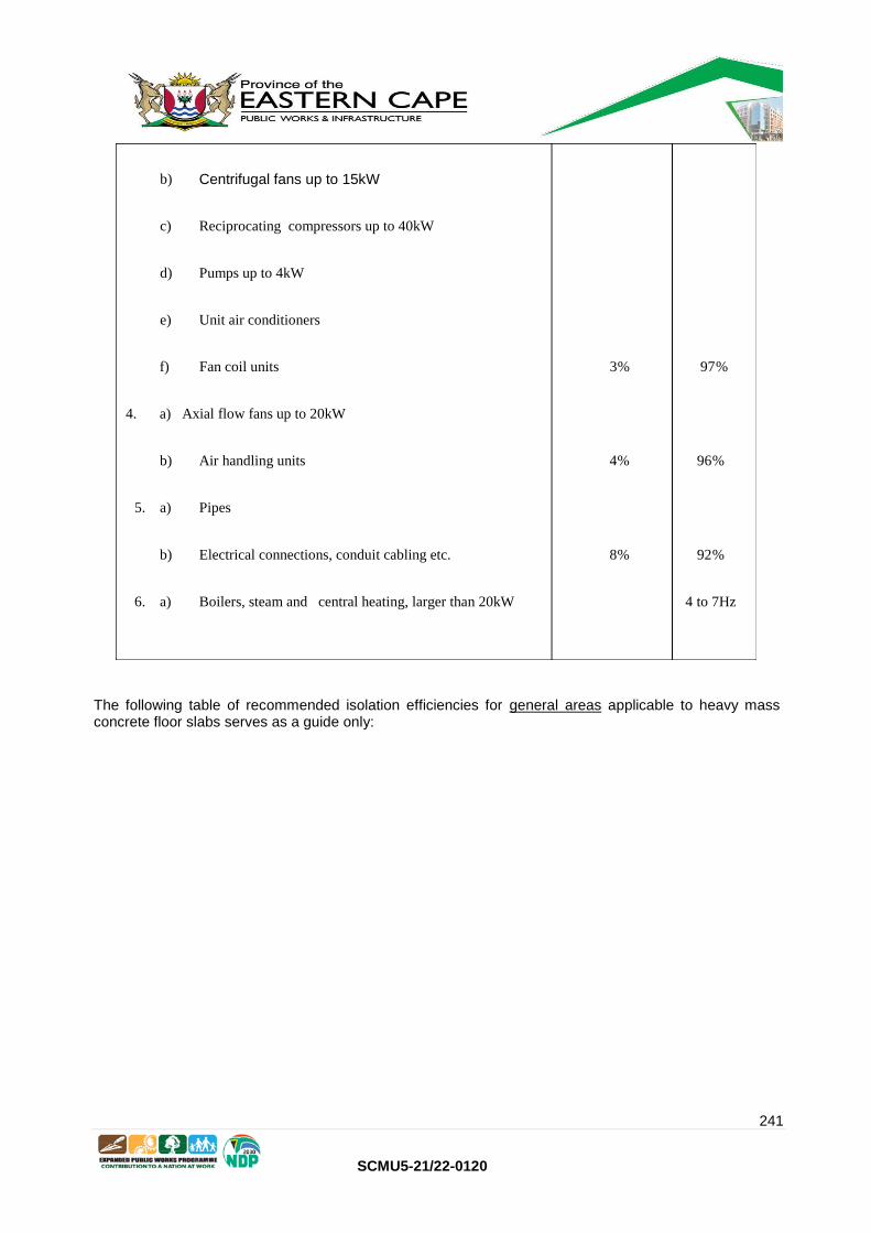
241
SCMU5-21/22-0120
The following table of recommended isolation efficiencies for general areas applicable to heavy mass concrete floor slabs serves as a guide only:
b) Centrifugal fans up to 15kW
c) Reciprocating compressors up to 40kW
d) Pumps up to 4kW
e) Unit air conditioners
f) Fan coil units 3 % 97 %
4. a) Axial flow fans up to 20kW
b) Air handling units 4 % 96 %
5. a) Pipes
b) Electrical connections, conduit cabling etc. 8 % 92 %
6. a) Boilers, steam and central heating, larger than 20kW 4 to 7Hz

242
SCMU5-21/22-0120
Selection of vibration isolation equipment and in particular, mountings for equipment and machines, shall be done with due regard to the forcing frequency of the driven machinery and the mounted natural resonant frequency of the machine.
In the case of installation of equipment on upper floors, suspended floors, roofs etc. it is of prime importance that floor stiffness, floor, deflection and natural frequency of the floor be taken in to consideration to ensure that resonant conditions cannot occur.
Critical Areas Transmissibility Isolation
Efficiency
1. a) Centrifugal compressors and chillers. 5 % 95 %
2. a) Centrifugal fans larger than 15kW.
b) Reciprocating compressors larger than 40kW
Pumps larger than 4kW % 8 92 %
3. a) Axial flow fans larger than 20 kW
b) Centrifugal fans up to 15kW
c) Reciprocating compressors up to 40kW
d) Pumps up to 4kW
e) Unit air conditioners
f) Fan coil units % 10 % 90
4. a) Axial flow fans up to 20kW
b) Air handling units % 15 85 %
5. a) Pipes
b) Electrical connections, conduit cabling etc. % 20 % 80
6. a) Boilers, steam and central heating, larger than 20kW to 15Hz 8

243
SCMU5-21/22-0120
Driven machinery and isolator deflections shall be carefully selected in these applications.
Equipment selection schedules shall be submitted to the Department for approval and shall contain full details regarding the forcing frequency, the natural mounting frequency, the static deflection and all other relevant information to evaluate vibration isolation equipment.
Should added mass inertia blocks be required to comply with these vibration isolation requirements, proper provision shall be made at tender stage for the provision of such.
3.15.3 Damping
Where static deflections in excess of 8mm are indicated, steel springs shall be employed incorporating acoustic sound pads in series with the spring.
The horizontal stiffness of the springs shall not exceed that in the vertical, in particular for systems mounted at vertical frequencies below 5Hz.
Low frequency mounts shall incorporate rubber snubbers to accommodate extreme horizontal or vertical motions such as can occur near resonance during start up.
The snubbers shall however not be relied upon to provide the necessary horizontal stability of the machine in normal operational conditions.
Spring layouts and inertia blocks shall be employed to avoid this situation.
For static deflections below 8mm, rubber in sheer mounts may be used provided the frequency is above 6Hz.
For small static deflections less than 4mm and particularly for high-speed machines and general acoustic isolation, ribbed rubber neoprene composite pads may be employed subject to the specified requirements.
No equipment shall be installed in critical areas without correct and approved vibration isolation.
Sufficient stability and damping shall be incorporated in the mountings to minimise the movement of the machine during start up or changes in the operating conditions.
The selection of mounts shall take proper cognisance of unequal distribution of the mounting weight of equipment and rotational and/or pressure forces acting thereon.
3.15.4 Pumps
All pumps with their motors shall be mounted on a base frame, which shall be installed on concrete plinths.
In addition it is required that pumps installed indoors and in critical areas shall be installed on anti vibration mountings with inertia mass bases with mountings selected for correct static deflection.
Bases for pumps in non-critical areas shall be installed on rubber in sheer mounts as a minimum, depending on the pump selection and locality of the pump.
Where required in the supplementary specification, pumps shall be totally enclosed in acoustic panelling to reduce noise breakout to the immediate vicinity and surrounding areas.

244
SCMU5-21/22-0120
3.15.5 Fans
3.15.5.1 Centrifugal Fans
No centrifugal fan shall be selected in a class range other than Class 1 or 2 and the rotating speed of the fan at duty point shall not exceed 1 440 r/min.
Centrifugal fans in critical areas and fans above 7,5kW shall in all cases be mounted together with the drive motor on anti-vibration mountings together with the correct inertia mass.
3.15.5.2 Propeller Fans
Propeller fans shall comply with the criteria already laid down and shall be carefully selected for the highest possible efficiency with due regard for the noise criteria.
Propeller fans in excess of 0,5kW and of rotational speed higher than 800 r/min shall, in addition to the requirements already laid down, be mounted on correctly selected and installed anti-vibration mountings to reduce possible vibration transmission to surrounding structures.
3.15.5.3 Axial Flow Fans
Axial flow fans shall be selected for the highest possible efficiency and comply with the noise criteria specified. In critical areas no fan shall be installed without attenuators on inlet and outlet sides.
In addition it will be required that the fan as a whole be mounted on anti-vibration mountings and where specified in the supplementary specification, it may be required for the fan to be enclosed in acoustic panelling.
No axial flow fan may be installed without anti-vibration mountings to match the fan characteristics and in critical areas it may be required for the axial fan to be provided with inertia mass to match.
Fan rotational speeds specified in the supplementary specification shall not be exceeded.
3.15.5.4 General
No fan may be directly connected to ducting either on the inlet or outlet sides, approved flexible connections shall be provided between the fan and the ducting distributing the air.
Where fan noise characteristics cannot meet the requirements of this specification such fans shall be replaced or other approved steps taken by the contractor at his own expense until the installation meets the requirements.
3.15.6 Piping
3.15.6.1 General
Under no circumstances may any piping be directly connected to noise generating equipment such as pumps, chillers, cooling towers etc.
Connections to such equipment shall be made with correctly selected flexible rubber type connectors of the spherical type.

245
SCMU5-21/22-0120
In critical areas double spherical rubber type isolators immediately adjacent to the noise generating machine will be required.
3.15.6.2 Pipe Penetrations Through Walls
Under no circumstances will pipe penetrations through walls be permitted where the pipe comes in direct contact with the surrounding wall or structure.
Proper sleeves of approved materials shall be fitted at wall penetrations.
3.15.6.3 Pipe Supports
In all critical applications and within the first ten metres of all equipment, it is required that pipe supports shall be of the flexible type, correctly selected for the application and with the correct static deflection.
Depending on the application spring mounting will in all probability be required.
Any other areas and applications at risk of noise or vibration transmission to the surrounding structure similarly require pipe mountings isolated from the structure.
Pipe supports fixed to sensitive building elements will not be permitted.
3.15.7 Sound Attenuators
Where required, in order to comply with the noise and vibration criteria already laid down, or where specified in the supplementary specification, sound attenuators shall be provided for ventilation and all other plant (Duct mounted and/or as applicable).
Primary sound attenuators shall be installed near or in the plantroom.
The attenuators selected shall match the specific fan or plant characteristics to ensure the correct insertion loss to meet the sound criteria laid down.
Unless otherwise specified, sound attenuators shall be installed with flexible connections at the inlet and outlet connections.
The sound attenuators shall in addition be selected to produce the minimum pressure loss across the attenuator coupled to the least re-generated noise level produced by the flow through the attenuator.
Unless otherwise specified, air path sound attenuators shall be manufactured from galvanised sheet steel with the sound absorption material moisture repellent and erosion resistant up to 20 m/s air speed, and preferably flange connected.
Wherever possible attenuators shall be proprietary type supplied by the same manufacturer as the plant manufacturer to ensure complete compatibility.
Where not clearly indicated on the drawings, attenuators shall in all cases be provided at points where supply and return air ducting leaves the plantroom and shall be installed to prevent noise breakout from the plantroom via the ductwork.
246
SCMU5-21/22-0120
The internal free area of sound absorbers shall be not less than the cross sectional area of the connecting duct as indicated on the drawings.
Field fabricated type sound absorbers shall be made as follows:-
All sides of rectangular ducting shall be double walled with the inner walls perforated with 10mm holes at 25mm centres. The space between the two sidewalls shall be divided into 3 unequal sections by means of 25mm thick cement fibre panel strips and filled with glass wool. The lining thickness shall be at least 80mm.
Circular ducts shall be lined as specified above except that the lining thickness shall not be less than 100mm.
3.15.8 Air-Borne Noise
Selection and installation of all items such as valves, traps, grilles, diffusers, dampers, jet outlets, nozzle outlets, transformation pieces, take-offs, etc. shall be carried out in such a manner to ensure compliance with the noise criteria laid down in this specification. Items shall be carefully selected to reduce generated noise levels to accepted levels and with minimum air pressure loss.
Items such as dampers, volume control items etc., shall be carefully selected with due consideration for noise regeneration in all possible positions of such dampers or items to ensure compliance in all positions.
All pipe penetrations through walls and structures shall be provided with a 25mm thick soft neoprene or similar approved material sleeve surround to ensure that no direct contact between the duct and wall occurs. For plastered walls the plastering shall be cut back to the outer edge of this sleeve.
3.15.9 Room Units
Where room units such as fan coil units are used, it is essential that the acoustical characteristics of such units are considered during selection and that they are installed to ensure compliance with the noise criteria laid down.
The sound pressure level from these machines shall be within the set criteria throughout the frequency range.
3.15.10 Noise to the Exterior
Where specified in the supplementary specification, additional measures shall be taken to prevent or reduce noise breakout to the exterior from the plantrooms.
In critical areas it is essential that all possible steps be taken and be allowed for at tender stage to ensure compliance with the requirements laid down.
No allowance shall be made for screening or attenuation with distance in calculating requirements.
3.15.11 Electrical Connections
In critical areas no conduit or armoured cabling may be connected directly to equipment. Flexible connections shall be used in these applications.
In other applications cabling shall be connected to equipment with long radius bends. No sharp corners or bends in cabling may be used.

247
SCMU5-21/22-0120
Electrical connections shall not impede anti-vibration mountings and shall not convey vibrations or sound to the structure or building elements.
In critical areas cabling, trunking etc. shall be supported in a manner to ensure no vibrations are conveyed to the structure. Supporting from sensitive elements of the structure will not be permitted.
Where floating floors, acoustical separating elements etc. are used in a structure, flexible connections, conduit etc. shall be used at all crossover points.
3.15.12 Testing
When called upon to do so by the Department, the Contractor shall provide at his expense, all necessary equipment required ascertaining compliance with noise and vibration elimination in the installation.
The instruments provided shall be calibrated by an approved Authority and shall be capable of measuring sound and vibration levels integrated over a period of time.
The instrument to measure sound pressure levels must be capable of reading sound levels in dBA as well as the sound level at the international octave band centre frequencies of 31,5 Hz, 63 Hz, 125 Hz, 250 Hz, 500 Hz, 1000 Hz, 2000 Hz, 4000 Hz and 8000 Hz as a minimum.
The instrument to measure vibration levels shall be calibrated in nano m/s over the integration period.
In the event of such tests indicating insufficient provision for eliminating airborne noise and vibration transmission, the Contractor shall at his expense rectify the installation as necessary and the tests shall again be executed until satisfactory results are obtained.
Final approval of the noise and vibration levels shall be at the sole discretion of the Department.
3.16.0 ELECTRICAL EQUIPMENT AND INSTALLATION
3.16.1 Unless otherwise stated in the Supplementary Specification Tenderers must allow in their price for the complete electrical installation and wiring.
3.16.2 All electrical equipment and wiring shall be in accordance with the current issue of the Department's Standard Specification for Electrical Equipment and Installation for Mechanical Services. Copies can be obtained from the Department, Private Bag X65, PRETORIA, 0001.
3.16.3 Power terminal points will be as specified in the Supplementary Specification.
3.16.4 All motors over 5kW shall be provided with an approved electronic type motor protection unit in addition to the protection called for in the Standard Specification for Electrical Equipment and Installation for Mechanical Services.
3.16.5 Clause 1.2.1 (a) of the Standard Electrical Specification shall read "The South African Bureau of Standards Code of Practice for the Wiring of Premises as amended".

248
SCMU5-21/22-0120
3.16.6 The fault level of the steam installation distribution board shall be as specified in the Supplementary Specification.
3.16.7 In the case of small wiring direct from busbars, e.g. voltmeter supply, suitable protection fuses shall be mounted directly onto the busbars.
3.16.8 The possibility of inadvertent contact with live terminals shall be avoided at all cost. All apparatus and wiring behind readily accessible hinged doors or panels shall be protected against finger contact by means of insulating panels (perspex or similar approved material) or other approved method. Busbar mounted voltmeter fuses shall be mounted on insulated back plates to afford complete safety from hand contact with busbars or other conductors in the immediate vicinity.
3.17.0 SELECTION OF EQUIPMENT
13.17.1 All equipment shall be selected with due regard to the installation site conditions, particularly with respect to;
- altitude
- ambient temperatures
- atmospheric conditions
3.17.2 Equipment shall at all times be selected to operate within the limits recommended by the particular manufacturer.
3.17.3 Where equipment will be required to operate at conditions deviating from the manufacturer's standard selection tables, re-rating shall be done strictly in accordance with the manufacturer's methods.

249
SCMU5-21/22-0120
SECTION 4
CONTENTS
Clause Description Page
4.0
Technical Requirements - Equipment and Materials
4.1
4.1.0
General
4.1
4.2.0
Steam Boilers
4.2
4.2.1
General
4.2
4.2.2
Horizontal Boilers
4.2
4.2.3
Vertical Boilers
4.5
4.2.4
Boiler Mounting and Fittings
4.6
4.2.5
Steel Stacks
4.8
4.2.6
Grit Arrestors
4.9
4.2.7
Induced Draught Fans
4.10
4.2.8
Automatic stokers – general
4.10
4.2.9
Automatic Control
4.11
4.3.0
Hotwell tank and stand (feedwater)
4.12
4.4.0
Water treatment plant
4.13
4.5.0
Steam flow meter
4.15
4.6.0
Boiler feed pumps
4.16
4.7.0
Training of employers staff
4.16

250
SCMU5-21/22-0120
4.8.0
Performance testing
4.16
4.9.0
Steel platforms, walkways and cat ladders
4.17
4.10.0
Coal handling equipment
4.18
4.11.0
Pipework and fittings for working pressure up to 1000kPa
4.19
4.12.0
Thermal insulation
4.26
4.13.0
Condensate pipework
4.28
4.14.0
Condensate tanks
4.29
4.15.0
Calorifiers
4.29
4.16.0
Hot water storage cylinders
4.30
4.17.0
Electrode boilers
4.30
4.18.0
Water flow meters
4.32
4.19.0
Steam heated baseboard heating units
4.32
4.20.0
Steam heated fan convectors
4.33
4.21.0
Steam heated hot water urns
4.34
4.22.0
Fuel oil burners
4.35

251
SCMU5-21/22-0120
ST.PWD.VII i
STANDARD SPECIFICATION
FOR
STEAM BOILER INSTALLATIONS
SECTION 4
4.0 TECHNICAL REQUIREMENTS - EQUIPMENT AND MATERIALS
4.1.0 GENERAL
4.1.1 The design, manufacture, installation and operation of the equipment shall comply fully with all the relevant requirements of the Atmospheric Pollution Prevention Act 45 of 1965, as amended, and any regulations promulgated thereunder.
4.1.2 Written permission shall be obtained from the local authority Chief Air Pollution Control Officer for the area where any new boiler is to be installed.
4.1.3 The Contractor shall supply and install all notices and warning signs that are required as set out in the relevant regulations and Acts, and/or by these documents.
4.1.4 The Contractor shall apply in good time to the Department of Labour for permission to erect the boiler/s on behalf of the Department.
All documents, drawings, certificates etc. required under the regulations of the Occupational and Safety Act and by the local authority shall be completed by the Contractor and submitted on behalf of the Department.
Fees payable in this respect shall be allowed for and included in the tender price.
A duplicate set of all documents shall be submitted to the Department's Regional Representative.
Erection of the boiler/s may only proceed after submission to the Department's Regional Representative of the provisional permit issued by the Department of Labour.
Any delay caused to the contract due to late submission of the required documents may result in the relevant penalty clause being applied to the contract by the Department.
4.1.5 It is a condition of tender that Tenderers allow in their tender price, over and above their normal labour force employed on the contract, to be in attendance on the day/s of inspection of the boiler/s by the Inspector of Machinery and to provide all assistance, instrumentation, lighting etc. that will be needed for such inspection.
252
SCMU5-21/22-0120
4.1.6 Boilers shall be rated at MCR (maximum continuous rating) for the pressure and site conditions specified in the Supplementary Specification supplying saturated steam at maximum possible dryness factor.
4.1.7 Boiler rating shall be based on the particular coal grade, size and quality specified in the Supplementary Specification.
Tenderers shall submit written guarantees with their tenders stating maximum specified fuel consumption of the boiler as tendered in kg steam per kg coal at specified MCR.
The MCR and specified fuel consumption must be guaranteed under fully automatic conditions, operating normally in-situ at the specified site and shall be maintained without any sign of priming, foaming or carry over from the boiler into the steam lines.
4.1.8
Boilers shall be subjected to certification by an independent, registered and recognised Inspector Authority and the Contractor shall supply the Department with original certificates issued by the Inspector Authority before first delivery will be considered.
Boilers shall be inspected and passed by the Inspection Authority before leaving the
manufacturer’s works.
4.1.9
A manhole or manholes shall be provided for each boiler to enable internal inspections (as
applicable) and where necessitated by the boiler configuration hand holes shall be fitted to
enable proper internal cleaning when necessary.
4.1.10
Boiler chamber volumes, fans etc. shall be suitably sized and matched to suit the site conditions,
particularly high altitude applications.
4.2.0
STEAM BOILERS
4.2.1
GENERAL
Steam boilers shall be manufactured, designed and rated strictly in accordance with BS 2790
"Specification for design and manufacture of shell boilers of welded construction".
4.2.2
HORIZONTAL BOILERS
4.2.2.1
Horizontal boilers shall be of proven design and manufacture, high efficiency, coal fired,
wetback, packaged shell and fire tube type.
4.2.2.2
Each boiler shall be complete with at least the following:
• horizontal chain grate stoker/s
• two off electrically driven feedwater pumps with feedwater controls

253
SCMU5-21/22-0120
• feed check valves
• two lockable safety valves piped to outside boiler house
• one pressure gauge with at least 250mm dial and isolating valve
• inspector's test cock with flange
• air release valve/s
• high and low level water alarms with valves and blowdown valves
• blow through drain piping shall be done in copper tubing from the fittings to the
blowdown pit
• induced draught fan
• forced draught fan
• instrumentation and automatic controls for combustion and load control
• integral pipework
• blowdown valves with keys, piped to blowdown sump
• steam/water sampling points
• soot blowers with steam stop valves
• ash removal valve and trolley
• feed hopper
• custom made platforms and cat ladders for access to all components, to form an
integral part of the boiler construction
• two shielded water level gauges with blowdowns and valves
• control panel
• draught gauges
• crown valve
• grit arrestor/s and stack as specified, complete with interconnecting ductwork
• fittings to function as complete unit
• dual Mobrey or equal water level control with bypass and isolating valves
4.2.2.3 Combustion shall take place under balanced draught conditions in the combustion chamber, under fully automatic controls.
4.2.2.4 The boiler shall be mounted on steel base frames ready to be placed on foundation plinths. Wherever possible boilers shall be supplied fully packaged and complete.
4.2.2.5 An ash discharge port with cast iron swing type valve shall be provided for ash removal from the grate discharge end.
Each boiler shall be provided with its own matching standard bin trolley for carting ash away. When in position underneath the boiler, the trolley shall seal neatly against a cast iron wedge plate fitted to the ash discharge port.
When the trolley is removed the swing type valve shall seal the port off air tight to maintain set combustion conditions.
Trolley wheels shall be large diameter solid rubber tyre type with the tyres protected with radiation shields.

254
SCMU5-21/22-0120
4.2.2.6 Boilers shall be fitted with at least two soot blowers each, to enable cleaning fine gas passages such as reversed chamber tubeplate and first tube pass to maximise operational time between boiler shutdowns.
Soot blowing must be possible with the boiler on range, fully operational.
4.2.2.7 Access doors shall be fitted to the furnace chamber, front and rear.
The doors shall be refractory lined with proper seals and easily removable.
4.2.2.8 Unless otherwise specified the stack shall be supported off the boiler.
Stack height and material shall be as specified in the Supplementary Specification.
Material thickness shall be not less than 4,0mm (for stainless steel) and the stack shall be anchored with galvanised steel cables.
4.2.2.9 A full set of special tools must be provided to enable maintenance to be done by the Department’s staff. The set must include all special tools for the stoker, soot blowers etc., including cleaning brushes and rods. The tools must be neatly mounted together on a steel bracket mounting and fixed to the wall of the boiler house.
4.2.2.10 All ducting between boiler, grit collector and induced draught fan shall be of 6mm mild steel welded
Construction and flanged with sufficient bolted inspection and cleaning openings.
At least four (4) connection points shall be provided in the ducting, one for temperature readings, one for combustion analysing, one piped to a magnehelic type pressure gauge and the fourth piped and valved for connecting a CO2 analyser.
4.2.2.11 The stoker shall be of the continuous chaingrate type with electrically controlled speed, infinitely variable over the range of the grate speed as supplied. It is essential that the stoker has a large effective area to allow for effective burning of the coal delivered to site, as is, without loss of output.
A withdrawal frame on large wheels shall be provided for each boiler house to enable easy stoker withdrawal. The stoker must withdraw as a complete unit.
The chain links must be cast-iron and must allow proper and uniform air distribution over the whole of the grate fire area. Link shafts must be withdrawable to enable replacing of individual links.
Forced draught ventilation through the grate is required with adjustable undergrate dampers. The dampers must be adjustable when the boiler is in operation.
A manually adjustable guillotine door is required to allow varying the thickness of the coal bed on the grate. A radial door must be provided to close off the boiler front when required.

255
SCMU5-21/22-0120
The manufacturer’s standard coal hopper shall be provided and must be at such a height and shaped as to allow filling by lashing manually.
The stoker control shall form an integral unit with the boiler controls, efficient combustion must be maintained under all conditions.
4.2.2.12 The induced draught fan shall be mounted on the boiler within the support framework of the stack with access to all service points and ease of removal of motor, bearings and fan shaft and impeller.
The fan shall be of the single inlet centrifugal type with self-cleaning impeller mounted on ball or roller bearing supports. The bearings shall be air cooled without overheating at any load.
The fan casing shall enable removal of the impeller and shaft without removal of any duct work or support structure.
A control damper functioning off the normal boiler controls shall be built into the ductwork between the fan section and the grit collector.
4.2.2.13 A single inlet forced draught fan of the centrifugal type shall be fitted to the stoker for control of stoker airflow and combustion chamber pressure.
Airflow shall be regulated by damper control forming an integral part of the control system.
4.2.2.14 Each boiler shall be provided with 2 soot blowers in the rear second pass tubes and 2 soot blowers in the front third pass tubes.
A stainless steel screw type grit extractor shall be fitted to the rear of each boiler to enable the removal of grit from the return chamber. The extractor must be hand operated and of robust construction suitable for the high temperature application.
4.2.2.15 The following spares shall be provided with each boiler as a minimum;
4 - Sets of water gauge glasses and cover shields
1 - Tube brush rod and 2 brushes
6 - Sets mineral fibre mud door gaskets
2 - Sets mineral fibre furnace access door gaskets
1 - Mudhole door spanner
1 - Furnace door spanner
1 - Smoke box door spanner
4.2.2.16 Each boiler shall be fitted with at least two draught gauges mounted on the control panel and piped to the boiler.
One photohelic gauge shall measure the pressure difference across the grate and the other magnehelic gauge the pressure between boiler and grit arrestor relative to the atmosphere.
256
SCMU5-21/22-0120
4.2.2.17 Liquid crystal display is required on the boiler control panel indicating stoker speed and damper positions to forced draught and induced draught fans.
4.2.2.18 Where specified in the Supplementary Specification one portable CO2 analyser complete with spare chemical charges shall be supplied with each boiler installation.
4.2.3
VERTICAL BOILERS
4.2.3.1
Vertical boilers shall be of the underfeed, coal fired, multi-tube, water-tube or flame tube type.
4.2.3.2
Unless otherwise specified in the Supplementary Specification each boiler shall be complete with
at least the following;
• Underfeed stoker with feed hopper and forced draught fan induced draft fan
• Two electrically driven feed water pumps
• Extended steel base frame
• Cleaning doors and handholes
• Secondary overfire air
• Instrumentation and automatic controls
• Integral pipework
• blowdown valve/s with key, piped to blowdown sump
• steam/water sampling points
• ash removal tools and trolley
• custom made platforms and cat ladders for access to all components
• two shielded water level gauges with blowdowns and valves
• crown valve
• grit arrestor and stack as specified
• fittings to function as complete unit
• feed check valve/s
• two lockable safety valves piped to outside the boiler house
• one pressure gauge with at least 250mm dial and isolating valve
• inspector's test cock with flange
• air release valve/s
• blow-through drain piping in copper tubing to blowdown sump
• draught gauges
• Control panel
4.2.3.3
Each boiler shall be provided with its own standard wheeled bin trolley for carting ash away.
The trolley wheels shall be large diameter solid rubber type with the tyres protected with radiation
shields.

257
SCMU5-21/22-0120
4.2.3.4
Each boiler shall be fitted with a balanced secondary air system to enhance combustion.
The secondary air installation shall comprise of an independent, floor mounted centrifugal fan, connected to the boiler with steam quality pipe air ducts.
The secondary air piping shall be installed in the space surrounding the stoker retort. It shall be shaped in the form of a ring and shall be fixed to the inner face of the extension skirt. A minimum of three riser ducts shall be welded to the ring.
The secondary riser ducts shall be evenly spaced over the perimeter of the boiler, and shall terminate with specially designed cast-iron nozzles in the combustion chamber.
The nozzles shall be designed to maintain a secondary air jet to penetrate the full width of the combustion chamber.
The ring, risers and cast iron nozzles shall be built into the refractory brick lining.
The nozzles shall discharge at a height of approximately 150mm above the top of the retort. Tenderers shall submit full details and drawings of the secondary air system offered.
4.2.3.5 At least two heavy duty, cast iron refractory lined hinged de-ashing doors shall be provided in
each boiler extension skirt, one to either side of the stoker centreline. Each door shall be at least 300mm
high x 450mm wide.
The doors shall be positioned to ensure that the fire can be cleared without drawing tools across the centre of the fire.
4.2.3.6 Adequate space must be ensured around the boiler to enable clinker removal.
4.2.3.7 Where necessary, high altitude application boiler skirt heights shall be raised to achieve correct combustion volume and to improve cleaning facilities.
4.2.3.8 Unless otherwise specified in the Supplementary Specification only underfeed stoker fired units shall be provided with combustion taking place under forced draught conditions in a combustion chamber containing the retort and surrounding refractory brickwork.
4.2.3.9 In the event of a hand-fired unit specified combustion shall take place under natural draught conditions in a combustion chamber containing a fixed grate.
4.2.3.10 The following shall be fitted for inspection purposes;
i) manhole for access to the waterside of the furnace uptake ii) Fire door for access to the fire side of the furnace iii) Handholes for every crosstube
4.2.4 BOILER MOUNTINGS AND FITTINGS
4.2.4.1 Boilers shall be provided with mounting pads for all fittings.

258
SCMU5-21/22-0120
4.2.4.2 Boiler fittings shall be of the flanged type and of approved manufacture.
4.2.4.3 The following fittings shall be mounted on each boiler, except where otherwise stated in the Supplementary Specification:-
1. Two sets of bronze or gunmetal water level gauge columns with suitable blow-down cocks or valves, protector frames, safety glass shields and gauge glasses. Blow-down cocks and valves shall be fitted with copper tailpipes, arranged to discharge into a tundish fitted to an independent drain pipe, piped to the blowdown pit in copper tubing.
The boiler blowdown pipe shall not be used for this purpose. The water level gauges shall be so situated and illuminated, that the water level in the boiler can at all times be readily observed from the operating floor of the boiler house.
2. Each boiler shall be provided with an integral self-contained control panel with vertical facia for the mounting of the switches and control regulators (Unless otherwise specified in the Supplementary Specification).
Each boiler must be fitted with the manufacturer’s standard and proven electric automatic combustion control. The control system shall automatically control the supply of fuel and air as well as the water level and grate stoker speed to maintain a constant steam pressure with load fluctuations as can be expected in this application. The pressure must be maintained without any priming, foaming or carry-over during load fluctuations.
The feed water control shall be vertical airbreak external type dual control incorporating feed pump stop/start, first low water, water alarm and cut-out and high water alarm. A further independent external single control operating as a second low water, water alarm and complete boiler lock-out protection shall be fitted. The combustion control shall be controlled from sensing steam pressure in the boiler drum and controlling the induced draught damper and the furnace flue pressure. Stoker speed control must be suitably linked to the forced and induced draught dampers to maintain the correct fuel-air ratio through the full operating range.
A changeover switch must be provided to enable manual operation when required with all alarms and protective devices in full operation.
All controls must be electrically operated and powered, matching site power.
The controllers shall be of the externally mounted, glandless, electrical type, fitted with float chambers and blowdown valves.
The float chambers shall be manufactured of close grained cast iron, with flanged connections, and float rods of monel metal. Float chamber covers shall be of carbon steel with stainless steel centre tubes.
The control contacts shall be of the air break type, and the water level regulators shall have adjustable differentials. They shall be capable of complete automatic control of the feed water pumps and alarms.

259
SCMU5-21/22-0120
The first controller shall automatically control the selected feed water pump. It shall be fitted with a first low water cut-out and alarm switch.
The second controller shall be provided with high water alarm, as well as a second low water cut-out and alarm switch.
The controllers shall in all respects be compatible with the boilers offered, and shall be fitted to the boilers in strict accordance with the manufacturer’s instructions.
The alarm levels and feed pump stop-and-start levels shall be set as prescribed by the boiler manufacturer.
Under normal steaming conditions with the water level in the boiler within the range of the feed pump stop and start positions, a green lamp shall be illuminated on the boiler control panel.
The high level alarm shall be an electric bell, which shall be set off when the water level rises above the set point. A white indicating lamp shall be illuminated simultaneously on the boiler control panel while the green indicating lamp shall be switched off.
The first low level alarm shall actuate an electric hooter fitted with volume adjustment, and illuminate an amber coloured lamp on the control panel.
The final low level alarm shall actuate an electric siren with volume adjustment and higher tone than the first. It shall illuminate a red indicating lamp on the boiler control panel and, at the same time, lock out the automatic stoker.
Muting switches shall be provided for the audible alarms and shall be wired in such a manner as to automatically reset the alarm system when conditions return to normal.
The blowdown valves for the controllers shall be of the flanged, hand operated, sequencing type, suitable for blowdown and isolation of the level controllers. Blowdown of float chambers and water connections shall be effected separately in a pre-set sequence. Ratchet mechanisms shall be incorporated in the handwheels to ensure that once the operation of the valves has started, they cannot be returned to normal working positions without going through the full sequence of blowdown procedure. Provision shall be made for locking of handwheels.
3. Each boiler shall be fitted with two double spring safety valves. The vent pipes from safety valves shall be run vertically to the outside of the boiler house at high level, above roof line, and suitable drain pipes shall be provided and run to the blowdown pit. Safety valves shall be adjustable and lockable.
4. Each boiler shall be equipped with a main steam stop valve, fitted as close to the boiler as possible. Where more than one boiler is connected to the same steam main a non-return valve shall be provided between each boiler and the range. Alternatively a combined main steam stop
and non-return valve (crown valve) may be provided.

260
SCMU5-21/22-0120
Boiler discharge connections to headers/ranges shall be connected to the top of such header/range and not the bottom.
5. Boiler blowdown valves shall be of the key type fitted with a safety device, which shall prevent the key from being withdrawn, unless the valve is fully closed. A separate blowdown pipe shall be provided for each boiler, piped to the blowdown pit.
6. A pressure gauge of not less than 150mm diameter shall be provided on each boiler. The boiler working pressure shall be indicated on the dial face by a permanent red mark. The range of the pressure gauge shall be approximately double the working pressure. The pressure gauge shall be mounted complete with siphon, isolating cock and inspector’s test connection.
7. A flanged fitting, complete with stop and non-return valves, shall be provided on each boiler for feed water pump connections.
8. Non-return valves shall be fitted in the feed line from each feed water pump.
9. Isolating valves to soot blowers where specified.
10. Access cat ladders and egg-crate platforms to provide access to all fittings for servicing.
4.2.5 STEEL STACKS
4.2.5.1 General
Steel stacks shall be provided for the boilers where indicated on the drawings.
The stack diameters and heights shall be as specified in the Supplementary Specification. Where no such dimensions are specified, they shall be in accordance with the requirements of the boiler manufacturer and the Local Authority, generally not lower than 20m above boiler room floor level.
Stacks shall be either self-supporting or supported off the boiler, as specified in the Supplementary Specification.
The stack shall be manufactured to its full height from stainless steel 3CR12 or 304, thickness not less than 4,0mm, or as specified in the Supplementary Specification.
Stacks and supports/stays shall be designed for a wind velocity of at least 260km/h.
4.2.5.2 Boiler supported stacks
Each boiler shall be provided with its own independent stack.
The stack shall be constructed in sections from welded stainless steel plates, the lower half to be at least 4,0mm thick. The entire mass of the stack shall be carried by the boiler. Where stacks pass through the boiler house roof, the necessary flashing and weather proofing shall form part of the boiler contract.

261
SCMU5-21/22-0120
A flanged connection shall be provided between the boiler and stack. Each stack shall be provided with a damper of the butterfly type of at least 6mm thick stainless steel plate, arranged for operation from the floor of the boiler house. Dampers shall be accessible for repairs or replacement by means of bolted inspection doors.
A collar with guy ropes and stays shall be fixed to the stack. Stays shall be firmly fixed to the building and ground anchors to the satisfaction of the Regional Representative. Brackets and ground anchors for stays shall form part of the boiler contract.
4.2.5.3 Self-supporting stacks
The stacks shall be of the welded and flanged stainless steel self-supporting type consisting of a conical bottom section and cylindrical top section. The plate thickness of the bottom section shall be at least 10mm and the top section at least 6mm.
The necessary reinforcing or bracing shall be provided where flues enter the stack.
A cleaning door shall be provided at the base of each stack.
An amply reinforced concrete base shall be included in the contract for each stack. The base shall be at least 2000mm deep.
Base design and stack support shall be based on site soil conditions and wind forces and design details shall be certified by a registered professional structural engineer. Contractor to submit engineer’s design and report for approval before construction commences.
4.2.6 GRIT ARRESTORS
Each boiler shall be fitted with a suitable grit arrestor as detailed in the Supplementary Specification.
Grit arrestors shall be of the multi-cell or integral cyclone type, and shall conform in all respects with the requirements of the Atmospheric Pollution Prevention Act of 1965, and their efficiencies shall be well above the limit allowed in the Act.
Tenderers shall allow for gas sampling downstream of grit arrestors with the boiler steaming at or close to MCR by an independent authority such as the CSIR who shall submit a written report indicating compliance or not with the Air Pollution Act.
Multi-cell grit arrestors shall be vertical high efficiency type.
Integral type grit arrestors shall be of the low resistance type, using natural draught.
The arrestor shall be installed between the boiler and the induced draught fan or the boiler and stack as applicable and must be accessible for cleaning and maintenance.
The grit arrestor shall be supported off the floor with a structural steel framework. The

262
SCMU5-21/22-0120
grit arrestor shall be manufactured from 6mm mild steel plate or thicker.
Walls of the collector or shells shall preferable be of cast iron with the bottom of the cone section and other erosion susceptible parts to be replaceable.
The arrestor shall be provided with a grit-collecting chute at the bottom with an automatic plate shutter. A matching grit collecting bin on wheels shall be provided for each boiler. The grit trolley must fit under the discharge chute to collect the grit when the shutter is opened without upsetting draught balance.
4.2.7 INDUCED DRAUGHT FANS
4.2.7.1 Induced draught fans shall be provided for all shell type, horizontal boilers and for vertical boilers where specified in the Supplementary Specification. The fans shall be of the multi-vane, centrifugal type, with radially tipped blades. Fans shall be statically and dynamically balanced, and shall be quiet in operation.
4.2.7.2 The fan casing shall be robustly constructed of steel plate and a cleaning door shall be provided in the casing.
4.2.7.3 The impeller shaft shall be carried in ball or roller bearings with cooling arrangements to provide satisfactory operation with gas temperatures over the full range of the application.
4.2.7.4 The induced draught fan shall be mounted on the boiler within the support framework of the stack with access to all service points and ease or removal of motor, bearings and fan shaft and impeller.
4.2.7.5 The fan shall be of the single inlet centrifugal type self-cleaning impeller.
4.2.7.6 The fan capacity shall be for the full flue gas flow at MCR at site conditions with sufficient margin to allow for expected foul up between annual services of flue gas passes through the boiler.
4.2.7.7 The fan casing shall enable removal of the impeller and shaft without removal of any duct work or support structure.
4.2.7.8 The fan and motor shall be the standard units normally supplied by the boiler manufacturer with the boiler model offered.
The motor shall be of the T.E.F.C. squirrel cage type with speed not exceeding 1450 rev/min.
4.2.7.9 A control damper functioning off the normal boiler controls shall be built into the ductwork between the fan section and the grit collector.
4.2.7.10 All ducting between boiler, grit collector, stack and induced draught fan shall be of 6mm mild steel welded construction and flanged with sufficient bolted inspection and cleaning openings.
Duct sizing shall be based on a gas velocity of not higher than 7,5m/s and ample provision shall be made for expansion and contraction in the ducting.
263
SCMU5-21/22-0120
4.2.8 AUTOMATIC STOKERS - GENERAL
Unless otherwise specified in the Supplementary Specification, an automatic stoker shall be supplied and fitted to each boiler.
Horizontal boilers shall be fitted with chain grate stokers and vertical boilers with underfeed stokers.
Each stoker shall be sized to provide the rated output of the boiler under normal working conditions, with the flues specified in the Supplementary Specification and at the site conditions specified.
Each stoker shall be driven by an electric motor of the totally enclosed fan cooled type. Motors shall be complete with switchgear for manual and automatic operation.
4.2.8.1 Underfeed type stokers - vertical boilers
Each stoker shall be complete with controls, infinitely variable hydraulic gearbox, hopper, burner, fan, motor, starter and safety devices.
The hopper shall be constructed of sheet steel. The feed screw shall be of alloy steel to resist the effects of abrasion, corrosion and heat, and shall run in a thick steel tube with joints provided between hopper and burner, for easy removal and replacement of the coal screw.
The retort section shall be made up of cast iron tuyeres and corner blocks.
The entire area surrounding the burners and retort shall be bricked up with matching refractory brickwork.
The coal feed tube shall be pressurised with damper adjustable forced draught air.
The stoker speed control shall be arranged to give infinitely adjustable feed control over its full range of rates of coal feed. The rate of air supply and coal feed shall be mechanically interlocked and arranged for both manual and automatic control.
A shear pin shall be fitted to the final worm shaft. The pin shall be readily accessible for replacement.
Drive mechanism shall be easily removable and provision shall be made for screw removal.
The stoker shall be the standard unit normally supplied by the particular boiler manufacturer.
4.2.8.2 Travelling grate stokers (refer clause 4.2.2.11)
Travelling grate stokers for horizontal boilers shall be installed as complete self-contained units. Where two stokers are installed in a double flued boiler the stokers shall be independent of each other.
Grate heat release per square meter grate area shall not exceed industry accepted standards.
The stoker grate shall consist of a series of rows of interlocking links, which shall form an endless chain. The links shall be manufactured from a special grade of cast iron, machined to ensure accuracy. The links shall be so designed as to afford maximum surface exposed to the cooling action of the air and the minimum

264
SCMU5-21/22-0120
heat-absorbing surface exposed to the fire bed. The links shall be held in place by means of high carbon steel link rods fitted in such a manner as to eliminate the necessity of any form of securing device for the end links.
The grate shall be driven by a totally enclosed fan cooled motor through an infinitely variable hydraulic gearbox driving the stoker front shaft. The grate speed shall be variable over the range applicable to the boiler size. A safety device shall be incorporated in the drive to safeguard against overloading. The grate must be capable of being hand operated in the event of a power failure.
On - off control will not be accepted.
The chain grate, drive and hopper shall be mounted on a main frame constructed from heavy section side members, substantial stays on the upper side and a bottom plate of ample proportions. The chain tracks shall be manufactured from high carbon steel and shall give continuous support to the grate under the driving links. The rear end of the grate shall be supported and guided by a roller unit fitted with robust screened bearings and revolving on a fixed shaft. The stoker shall be capable of being withdrawn from the boiler as a unit.
An even distribution of air across the width of the grate is essential and the necessary dampers and controls for regulating the supply of air through the length of the bed shall be provided and arranged for convenient operating at the firing floor level
4.2.9 AUTOMATIC CONTROL
4.2.9.1 In addition to the water level controllers specified boilers shall be equipped with reliable combustion control units (where specified in the Supplementary Specification).
Each boiler shall be provided with an integral self-contained control panel with vertical facia for the mounting of the switches and control regulators.
Each boiler shall be fitted with the manufacturer’s standard and proven electric automatic combustion control. The control system shall automatically control the supply of fuel and air as well as the water level and grate speed to maintain a constant steam pressure with load fluctuations. The pressure must be maintained without any priming, foaming or carry-over during the load fluctuations.
4.2.9.2 The combustion control shall be controlled from sensing steam pressure in the boiler drum and controlling the induced draught damper and the furnace flue pressure. Stoker speed control shall be suitably linked to the forced draught damper to maintain the correct fuel-air ratio through the full operating range.
A changeover switch shall be provided to enable manual operation when required with all alarms and protective devices in full operation.
All controls shall be electrically operated and powered.

265
SCMU5-21/22-0120
4.3.0 HOTWELL TANK AND STAND (FEEDWATER)
Hotwell tank and stand as specified in the Supplementary Specification shall be provided and installed in the boiler house in the position indicated on the drawing.
The tank shall be fabricated from 6mm mild steel plate suitably stiffened. The tank shall be mounted on 150mm x 100mm rolled steel joists. Where the tank is to be elevated it shall be mounted on a tubular or rolled steel joist stand which shall be suitably braced and stiffened. The height of the elevated tank will be indicated on the drawings.
The interior of the tanks shall be thoroughly cleaned and prepared and then painted with approved anti-corrosion paint.
The hotwell tank shall be complete with all fittings and outlets as on the drawings including the following;
i) A 460mm x 460mm hinged access door immediately above the ball valve shall be provided in the top of the tank for inspection and maintenance purposes.
ii) A cold water supply connection, located 300mm below the top plate, controlled by a ball valve, to discharge at least 300mm below the normal water level.
iii) 40mm Valved drain and overflow connections, with pipelines complete with water traps, to be run outside the building to the nearest gulley or drain-point.
iv) A 100mm vent pipe to be taken straight up through the roof of the boiler house. Suitable flashing and weather proofing shall form part of the boiler contract.
v) Suction pipes of the sizes specified, complete with valves and strainers, shall be provided at the bottom of the tank, and connected to the suction side of feed pumps.
vi) Condensate return connections of the size or sizes specified shall be manifolded near the top of the tank with the manifold arranged to discharge near the bottom of the tank. The manifold shall be provided with its own vent pipe separate of the tank vent, to outside.
vii) A shielded glass water gauge column, complete with isolating and drain cocks, shall be provided for water level indication. The diameter of the glass column shall be not less than 15mm o.d. and shall
be clearly visible from the firing floor.
viii) The stand support shall be of structural steel as per drawing and painted as specified.
4.4.0 WATER TREATMENT PLANT
4.4.1 General

266
SCMU5-21/22-0120
1. Water treatment equipment shall be provided and installed close to or beneath the hotwell tank as indicated on the drawings.
Tenders shall arrange for a water sample to be taken of the water available at the site and to have same analysed, prior to tendering.
Water treatment plant tendered shall be based on actual site water quality.
2. The water softening and dosing plant shall be capable of achieving the following feed- and boiler water conditions under all operating conditions:
i) Expected maximum make-up 60% of MCR (or as specified)
ii) Feed water analysis required:
Hardness - 5mg/l as CaCo3
Alkalinity - preferably due to Caustic Soda, 100ml sample to give
pink colour to phenolphthalein with 0,15ml of 0,1
Nitric acid
Oxygen content - not more than 0,05mg/litre
iii) Boiler water analysis required with normal periodic blowdowns;
Hardness - Nil
Total Alkalinity - 10 - 15% of T.D.S.
Phosphate - 100 - 170mg/l as Na3 PO4
T.D.S. - not more than 3000mg/l
Above shall serve as a guideline and final requirements shall be in accordance with the boiler manufacturer’s specifications and the Supplementary Specification.
3. The water treatment shall provide corrosion protection to all parts of the boiler and
the total Steam system in contact with steam, boiler feed water and condensate.
No priming, foaming or carry-over of any kind of the boiler shall be allowed and boiler water level shall remain stable under all operating conditions.
4.4.2 Water Softeners
1) A fully automatic base exchange water softener/s for the external treatment of boiler feed water make up water shall be provided to match site water and boiler feed water quality and hardness requirements.
2) Each independent feed water/ hotwell system shall be provided with its own water softener in the make-up water.

267
SCMU5-21/22-0120
3) Capacity of water softeners shall be based on 60% of boiler/s served MCR or as specified in the Supplementary Specification.
4) Each water softener shall be capable of operating for at least 24 hours before having to be regenerated, and shall be designed to suit the site water pressure.
If a water pressure booster pump is required it shall be allowed for in the tender price.
5) The softener shall function fully automatically and provision shall be made to eliminate the bypassing of hard water during generation. The unit shall be complete with at least the following:
a) Brine tank of polypropylene or fibreglass with lid with stainless steel type propeller mixer, all on 150mm raised platform.
b) Synthetic high capacity cation exchange resin.
c) Inlet, outlet pressure gauges.
d) Integrating water meter.
e) Test kit and operating instructions.
f) Isolating valves and all integral pipework.
The cycle control shall be from a twin measuring cell and not time clock or flow controlled. The twin-measuring cell shall be in continuous contact with the resin bed and the controls set for optimum salt consumption and minimum use of regeneration water.
Inlet and outlet pressure gauges as well as a integrating water meter similar and equal to Kent is required.
A test kit and a full set of operating instructions shall be provided.
All equipment shall be manufactured from corrosion resistant materials such as fibreglass and/or polypropylene.
4.4.3 Chemical dosing
1) Chemical dosing of the boiler feedwater is required. It is required that as a minimum oxygen scavenging shall take place at the point of dosage and with effective carbon dioxide neutralising in the condensate return system to protect condensate pipes, traps, valves etc.
2) Chemical dosing shall be done with packaged variable dosing units.
It shall comprise a 200l (min) polythene or fibreglass dosing tank, metering pump/s, tank and pump base, combined electrically driven propeller mixer/stirrer with stainless steel shaft and propellers, tank lid,

268
SCMU5-21/22-0120
metering pumps with capacity range variable to match possible tank concentrations for the required chemicals. Dosing shall be in to the feed pump suction main and the dosing pumps shall be suitable for use with corrosive chemicals.
3) The dosing pumps shall be interlocked with the boiler selected for operation as well as the particular feed pump operating at any moment of time to ensure that it stops and starts with the feed pump in operation so that dosing only takes place when a boiler feed pump is in operation. The dosing pump range shall be in the order of 2 to 50l/hour, matching boiler capacity and chemical feed rates.
4) The dosing unit shall be complete with all necessary piping, valves, electrical protection etc., and it shall be possible to service all parts and components with the boilers in normal operation.
5) The chemicals tendered for use shall be the manufacturer’s standard formulation for this type of application and must be freely available in standard concentrations and containers.
6) One set of chemical dosing equipment shall be provided for each boiler.
7) Automatic blowdown or controlled bleed off is not desired unless absolutely necessary and the
treatment applied must be suitable for an operation controlled blowdown programme.
4.4.4 Chemicals and salt
1) A full supply of chemicals, salt, etc., to enable 3 months of continuous use of the dosing and softening plant shall be supplied to the Department upon successful commissioning of the plant. The chemicals shall be handed to the Department in sealed containers and a signed receipt must be obtained from the Department’s representative.
2) Steam will be used for various processes, including the preparation of food. The chemical treatment must, therefore, be suitable for use with such processes and approved as such.
3) The chemical treatment shall provide protection against corrosion of boiler metal, steam and condensate reticulation systems and shall inhibit caustic embrittlement. Precipitation of sludge is not desirable and all solids shall remain in suspension.
4) The chemical solution shall contain softening agents, oxygen scavengers and corrosion inhibitors.
5) The chemical/s shall be injected into the pump suction lines and shall be arranged for individual dosing to each boiler.
4.4.5 Chemical Control Tests

269
SCMU5-21/22-0120
1) It is a condition of tender that the supplier of the dosing equipment enter into a separate service contract with the Department for the regular maintenance of the dosing plant only, dosage rate adjustment and for the chemical control analysis of the boiler water.
2) Chemical control tests shall be conducted at least once per month and the results thereof submitted to the Department.
Included in the monthly reports shall be recommendations on concentrations, dosage rates and blowdown operations.
3) Tenderers must indicate in their tenders whether the suppliers of the dosing
equipment are able to provide such a service and indicate the cost of the service on
the schedule of particulars.
4.5.0 STEAM FLOW METER
1) Where specified in the Supplementary Specification one combined steam flow and pressure recorder shall be installed in the position indicated on the drawings.
2) The flow and pressure ranges shall match the specified boiler requirements and expected total steam flow.
3) The recorder shall be mounted on the boiler house wall in a clearly visible and accessible position. Isolating valves shall be provided at the orifice plate tapping and at the recorder.
4) The complete installation shall be strictly in accordance with the manufacturer’s requirements.
5) Charts and ink shall be provided for 3 months continuous use.
4.6.0 BOILER FEED PUMPS
1) Each boiler shall be provided with two electrically driven multistage centrifugal pumps. It must be possible to select any one pump without interrupting the automatic control.
2) Pump capacity shall be at least 10% in excess of the boiler MCR at specified operating pressure with a non-overloading characteristic.
The pump motor shall be rated for all possible load conditions with an excess of at least 10% above the expected maximum pump load.
3) Pump and motor shall be mounted on a common baseplate on the boiler support framework.

270
SCMU5-21/22-0120
4) A pressure gauge with range 10% in excess of feed pump shut-off head shall be fitted in the common feed line from the feed pumps in a conspicuous position. The pressure gauge shall be provided with an isolating cock.
5) The pump impeller shall be of machined phosphor bronze or equal. Pump casing to be of cast iron and pump shaft stainless steel.
6) Pumps shall be fitted with non-return and isolating valves to enable servicing any pump with the boiler in use.
4.7.0 TRAINING OF EMPLOYER’S STAFF
4.7.1 Construction phase
It will be the intention of the Department to have two employees (future plant operators) nominated by the Department, working with the Contractor’s staff during the construction phase on site to enable them to gain a working knowledge of the installation as well as familiarise them with the various sections and elements.
It will be expected of the Contractor to utilise and develop their skills and instruct them from day to day as if they were his own employees. Salaries of the two employees will be paid by the Department.
4.7.2 Commissioning phase
The Contractor shall within reason involve and train the operating and maintenance staff of the Department during the commissioning phase to enable them to do commissioning after future maintenance shut downs.
4.7.3 Training in Operation
After the successful commissioning of the plant and it being used on a regular basis it is required that a suitably qualified employee of the Contractor shall spend 7 consecutive working days of 9 hours each in full attendance training the staff in the day-to-day operation and attendance and minor adjustments necessary to operate the installation successfully and efficiently.
4.8.0 PERFORMANCE TESTING
4.8.1 General
The testing of each boiler and all equipment forming part of this installation forms part of this contract. All testing shall be done by the Contractor at his expense in the presence of the Department’s representative. The Contractor shall supply all materials, equipment, labour, instruments etc. to facilitate the full and comprehensive testing required.
4.8.2 Boilers and Ancillary Plant
The following tests will have to be carried out on each boiler:

271
SCMU5-21/22-0120
a) Hydraulic pressure test and internal inspection as required and arranged with the Inspector of Machinery.
b) Testing of all automatic and safety apparatus and equipment.
c) Hydraulic pressure test on all steam and condensate lines in the presence of the Department’s Representative. Tests to be conducted at 150% main steam pressure and the whole system inspected for leaks.
d) All traps, strainers and condensate returns for proper functioning.
e) Proper functioning of combustion controls with special regard to efficient burning in the range 40% to 100% of continuous rating.
f) A continuous performance test of duration long enough to satisfy the Department’s Representative during which period the steam flow and coal consumed must be accurately measured. Instrumentation will also have to be provided to accurately measure the temperature and pressure of the steam and feedwater. Two representative coal samples will also be taken with proper airtight containers one of which shall be sent to a independent laboratory for analysis at the Contractor’s expense. The other sample will be kept by the Department for control purposes. A full analysis report in writing on the official letterhead of the sampling laboratory must be submitted to the Department within 10 days of the test.
4.8.3 Water treatment plant
After commissioning and during the training period water samples shall be taken to establish the correct functioning of the water treatment in clean, clearly labelled bottles;
a) Water after softener (make-up)
b) Water after dosing and before boiler
c) Condensate return from plant at entry to hotwell
d) Boiler water
The samples shall be taken twice daily and sent to an independent laboratory for analysis.
During the sampling period a close control shall be kept on blowdowns. All blowdowns, number and duration shall be properly recorded and submitted with the analysis report.
4.9.0 STEEL PLATFORMS, WALKWAYS AND CAT LADDERS

272
SCMU5-21/22-0120
1) Additional platforms, walkways ad cat ladders where specified in the Supplementary Specification, shall be installed in accordance with the arrangements shown on the drawings.
2) Platforms shall consist of lattice type grating cut to size and bolted on to strong angle iron frames,
which shall be free standing or supported off the walls of the boiler room.
3) The platforms shall be provided with tubular guard rails, not less than 1m high.
4) Cat ladders constructed of 40mm x 13mm mild steel flat sides and provided with 300mm long x 16mm mild steel rungs, riveted or welded into holes in sides at 230mm centres, shall be provided where shown on the drawings.
4.10.0 COAL-HANDLING EQUIPMENT
4.10.1 General
Where specified in the Supplementary Specification, coal-handling equipment shall be provided, as shown on the drawings.
Suitable connection chutes shall be provided between conveyors, elevators and hoppers and chutes.
4.10.2 Coal Elevators (En Masse Conveyors)
The handling capacity of the coal plant shall be compatible with the boiler capacity/capacities and the particular coal size and quality to be utilised on site, with particular reference to fines and duff content.
1) The coal elevator shall consist of a pressed steel casing of robust construction through which the coal is moved by an endless chain of appropriately shaped case hardened links. The casing shall consist of two separate ducts with the chain/links dragging the coal through the full half and the chain return through the empty side.
The casing sections shall be correctly aligned and shall be dust proof. Hardened wear resisting plates shall be provided at all bends on the inside of the coal duct and along the chain/link travel and slides.
2) The elevator shall be driven by a fixed speed totally enclosed fan cooled motor, through a reduction gearbox and a final chain drive with machined hardened sprocket. Provision shall be made to prevent the mass of the coal in the vertical casing from driving the unit in reverse when the driving motor is switched off. The elevator shall have shearpins for protection. A speed sensing control unit shall be provided to trip the driving motor whenever stoppages occur due to a mechanical fault. Motor coupling to gearbox shaft shall be of the hydraulic type.
3) A robust, manually operated cut off slide with handwheel and drive sprocket shall be provided at each bunker discharge opening, where applicable.

273
SCMU5-21/22-0120
4) Each elevator shall be provided with a discharge chute, which feeds directly into the choke of the matching screw conveyor or boiler hopper, where applicable.
4.10.3 Screw Conveyors
1) Screw conveyors shall consist of an electrically driven Archimedean screw in a steel or cast iron tube. The tube diameter shall be not less than 150mm. The tolerance between screw and sides shall be suitable for the type of coal to be used.
2) Where a screw conveyor is connected to an elevator, the capacity of the conveyor shall be greater than that of the elevator.
3) Screw conveyors shall be fitted with shearing pins for protection against mechanical faults and provision shall be made for access to the screw and shear pin when the conveyor becomes clogged or pin sheared.
4) The conveyor shall be manufactured in practical sections with easy access and screw removal.
4.10.4 Control of Coal Handling Plant
1) Each elevator/conveyor combination (where applicable) shall be controlled from high and low coal level limit diaphragm type micro or proximity switches situated in the chute and stoker hopper respectively. Each conveyor/elevator combination shall be provided with manually operated emergency overriding switches, which can be used in the event of high or low-level micro switch failure.
2) Combination conveyor and elevator motors shall be electrically interlocked to prevent conveyor operation when the elevator has stopped due to a mechanical fault and vice versa. Conveyor and elevator motors shall be started and stopped in sequence.
4.11.0 PIPEWORK AND FITTINGS FOR WORKING PRESSURE UP TO 1000kPa
4.11.1 General
1) Steam, condensate and feed water piping complete with all valves and fittings shall be provided and fixed in accordance with the layout shown on drawings, as well as standard drawing ME 700S/9 to ME 700S/22 which are bound into this standard specification.
2) Pipes shall be neatly run and properly supported. Where beams, stanchions, etc., interfere with the straight running of pipes, suitable offsets shall be provided so that pipes may follow the line of the walls both vertically and horizontally. Tenderers should make themselves conversant with complete drawings of the buildings concerned in order to ascertain the number and positions where such offsets will be required.

274
SCMU5-21/22-0120
3) Horizontal pipes passing through partitions and walls, shall be provided with sleeves made of medium class black steel pipe, large enough to leave a clearance not less than 6mm around the pipe and covering, if any. In new constructions, sleeves shall be built in.
4) Vertical pipes passing through floors shall be provided with sleeves of medium class galvanised steel piping. Sleeves shall be of proper length to pass through the entire floor construction, including fill, and shall provide the same clearance as above. Sleeves in concrete work shall be flanged at the bottom or provided with temporary centring caps and securely nailed or screwed to forms before the concrete is cast.
5) Exposed pipes passing through floors or walls shall be provided with floor, ceiling and wall finishing plates. Plates shall allow for expansion and contraction and shall be securely fixed to the sleeves.
6) Expansion loops and scale pockets with steam traps shall be provided where shown on the drawings and at such other positions as may be required. (See attached drawings)
7) As an alternative to the expansion loops, bellows type expansion joints may be offered, but
these shall be subject to approval by the Department’s Representative.
8) Bellows type expansion joints where approved, shall have internal and external sliding sleeves and shall be subjected to cold draw as recommended by the manufacturer.
Expansion bellows shall be manufactured from 18/8 stainless steel and shall be designed to withstand the test pressure of the system.
All expansion bellows shall be provided with external protection where exposed to damage.
All bellows expansion joints shall be capable of withstanding without damage, expansion movement of not less than 150% of the predicted maximum in the location for which it is intended. Bellows expansion joints which are strained during tests due to being wrongly located etc., shall at the Department’s Representatives discretion, be replaced by the Contractor at no extra cost to the Department.
Each bellow expansion joint shall be fitted with a clearly inscribed plate showing maximum working pressure, maximum and minimum operating lengths and direction of steam flow. They shall be installed strictly in accordance with the manufacturer’s recommendations.
4.11.2 Steam Piping
1) All steam piping shall be un-galvanised throughout and shall comply with ASA Schedule 40, seamless class or steam class to SANS 62 or BS EN 10255, as specified in the Supplementary Specification.

275
SCMU5-21/22-0120
2) All piping shall be entirely free from defects and rust or millscale and shall be factory coated with a suitable red oxide primer. All piping shall be suitable for a working pressure of 1000kPa with saturated steam.
3) Piping up to 50mm nominal bore may be screwed, while larger than 50mm nominal bore must be welded and flanged. All piping to be welded shall be suitably prepared and bevelled for welding.
4.11.3 Steam Fittings
1. General
All fittings shall be of the highest quality ungalvanised steam fittings.
All fittings of 50mm diameter and under may be screwed. The larger fittings shall be flanged. Where fittings are used sufficient unions or flanged joints must be provided to permit easy removal of equipment.
2. Screwed Fittings
Where screwed fittings are used, these shall be of heavy steam quality wrought steel fittings, which shall comply with BS EN 10241. These shall be threaded to BS EN 10226-1, 10226-2 and 10226-3. Malleable iron fittings may not be used.
Screwed fittings shall have their thread cut accurately square to the axis of the fitting to ensure straight and square pipework.
3. Welded Fittings
These shall be seamless carbon steel butt-welded fittings, and shall comply with BS 1640 Schedule 40.
4. Bends
All bends shall be of the long radius type, elbows may only be used on small pipe sizes where the special requirements are such as to render the use of bends impractical. All bends shall comply with BS 1640 Schedule 40. Elbows shall comply with BS EN 10241.
5. Reducers
Where reducers are used, these shall be either eccentric or concentric as appropriate. It is essential that, where reducers are used, the invert of the pipe is straight and free of any untrapped pockets or steps, which could accumulate condensate.
6. Tee Pieces
Screwed tee pieces shall comply with BS EN 10241. Welded tee pieces shall comply with BS 1640 Schedule 40. Tee pieces may be equal or reducing. The latter are preferred where a smaller branch is taken from a main.

276
SCMU5-21/22-0120
7. Nipples
Only tapered thread nipples made from heavy grade steam pipe may be used. Nipples may be long, short or hexagonal. Nipples will only be accepted up to 40mm nominal diameter pipe size.
8. Unions
All unions shall be of the wrought steel conical bronze seat type of steam union and shall comply with BS EN 10241. Malleable iron or flat face unions will not be accepted.
9. Flanges
All flanges shall be raised face machined steel flanges, which shall comply with BS 10 Table F. All flanges shall be suitable for welding in sizes above 50mm nominal bore, while screwed flanges may be used on pipes of 50mm nominal bore and smaller.
10. Gaskets
Gaskets shall either be metallic joint rings or they shall be made from graphited compressed mineral fibre with a minimum thickness of 1,6mm.
11. Valves
Steam valves for a working pressure up to 1500kPa and temperature up to 200ºC shall be of the globe valve type. Over and above this temperature and pressure, parallel slide valves shall be used.
For up to 1500kPa pressure and 200ºC steam temperature, valves of 50mm diameter and smaller shall have a bronze body, spindle of manganese bronze, seat and valve of 316 stainless steel which must be fully replaceable and a handwheel of pressed steel with a heat insulating insertion fitted. The screw-on bonnet shall contain a mineral fibre gland packing.
Valves larger in diameter than 50mm shall have a steel body, with a stainless steel seat, valve and spindle. The handwheel shall have a heat-insulating insert and may be of cast iron.
All valves shall be embossed indicating the make, manufacturer, working pressure and temperature.
12. Steam Strainers
Strainers shall be of the Y-leg type with bronze body up to and including 50mm diameter and cast iron body above 50mm. Strainers shall be fitted with stainless steel or monel metal screen mesh size 100 with screw on or bolted cap. The total free area of the screen shall be equivalent to at least twice the area at the entering port. All strainers larger than 25mm shall be fitted with a blowdown cock.
13. Pressure Reducing Valves
All pressure reducing valves shall be pilot valve operated and capable of handling steam quantities ranging from 10% to 100% of the total load, and with an operating pressure of ±25% of the nominal supply steam

277
SCMU5-21/22-0120
pressure. Downstream steam pressure shall not vary more than 1% over the range of 10% to 100% capacity. Pressure rise under dead-end conditions shall not exceed 1% downstream. The valve shall be embossed indicating make, manufacturer and operating conditions. The valve shall be flanged with flanges drilled to BS 10.
Table F.
Valves on dead-end legs must shut off tightly.
All wearing parts such as valve seat and valve diaphragms shall be made of stainless steel.
Means for adjustment of the pressure reduction shall be provided without the steam pressure on the reduced side fluctuating out of specified range.
All reducing stages shown on the drawings shall be in accordance with the standard stage shown on drawing ME 700S/19 attached.
14. Pressure Relief Valve
Pressure relief valves shall be of the adjustable spring loaded pop type. The body shall be bronze and suitable for the specified working pressure. The valve seat, and valve shall also be bronze or stainless steel. The spring shall be cadmium-plated steel, with spindle and spring plate being bronze. The valve shall be selected for the maximum possible flow and pressure allowing for a 15kPa pressure drop over the valve. The valve shall operate on 10% variation of the controlled pressure on full opening. The final setting of the pressure shall be locked by means of a padlock. The safety valve discharge shall be piped to a safe position outside buildings, where applicable.
Combined pressure reducing and safety valves are not acceptable.
15. Pressure Gauge
All pressure gauges shall not be less than 100mm diameter Bourdon Tube dial type gauges to BS EN 837-1. All gauges shall be supplied with siphon and cock to suit the pipe to which they are fitted.
All gauges shall have an error of not greater than ±2% as calibrated against a dead weight tester over the complete range of operation.
All gauges on a particular installation shall be of the same manufacture and shall be calibrated in kPa and shall be graduated to 50% above the working pressure.
16. Steam Traps
All steam traps are to be similar and equal to Hopkinson, Armstrong, or Spirax Sarco. Traps shall be suitable for the specified working pressure.
All steam traps used on a particular site are to be of the same manufacture. Steam traps are to be suitably chosen for their duty and submitted to the Department’s Representative for approval prior to ordering.

278
SCMU5-21/22-0120
Steam traps shall be of the float, inverted bucket or thermostatic type as specified in the Supplementary Specification and shall have the capacities specified under the conditions at which they have to operate. Float or bucket traps shall have bodies of cast iron or stainless steel, float and buckets of nonferrous alloy, and replaceable stainless steel valves and seats. Thermostatic traps shall have bodies of non-ferrous alloy, bronze bellows (or bimetal elements) and replaceable stainless steel valves and seats. All traps of the float or inverted bucket type shall be fitted with automatic air relief valves.
Traps shall be installed in accordance with maker’s recommendations. A pipe line strainer shall be provided before each trap.
A shut-off valve shall be provided before and after each steam trap and the trap shall be mounted between unions or flanges to facilitate easy removal, as shown on drawing ME 700S/15 and /16.
17. Sight Glasses
Sight glasses shall be made of bronze or gunmetal body, with glass window embedded between two mineral fibre graphite washers, of at least 60mm diameter free viewing area.
The sight glasses shall be installed downstream from traps and shall be suitable for the working pressure of the system.
The bezel shall be readily removable for easy cleaning.
18. Check Valves
Check valves shall be of the swing or lift type. The body, disc and seat shall be made of bronze.
The disc and seat shall be machined to allow for positive closing of the valve on backpressure. The valve shall be suitable for the specified working pressure.
19. Combination Sight Glass/Check Valve
A combination sight glass/check valve can be used in lieu of the single items as detailed above. This combined unit shall be of approved manufacture and shall be designed for the specified working pressure.
20. Steam Separators
Steam separators shall only be of a well-proven and approved manufacture. Units made up in the contractor’s or other works will not be acceptable.
21. Scale Pockets
Scale pockets shall be provided before all line traps as shown on drawings ME 700S/15 and - /16.
Scale pockets shall in all instances be of the same pipe diameter as the steam main, with a minimum length of 700mm extending below the branch-off to the line trap.
4.11.4 Pipe Joints

279
SCMU5-21/22-0120
1. General
The ends of all pipes are to be cleaned from burrs and rough edges before jointing.
2. Threaded Joints
All pipe threads shall be right-handed Whitworth standard taper pipe threads and shall comply with BS EN 10226-1, 10226-2 and 10226-3. Threaded pipe joints shall be made with either an approved steam pipe jointing compound or PTFE Tape.
All surplus compound or tape shall be cleaned off the joints before painting or finishing-off.
3. Welded Joints
All welded pipe joints shall be of a high standard and carefully prepared for welding.
All edges and holes shall be correctly bevelled and shaped. Where flame cutting is carried out, the surfaces shall be thoroughly cleaned by grinding, and all slag and oxidised material removed before welding commences.
Welded joints shall be thoroughly cleaned after welding and all slag and other foreign material removed before installation.
All welding shall fully comply with SANS 15607 as amended.
Where pipes are welded, Tenderers shall allow for one in ten welded pipe joints (chosen by the Department’s Representative) to be cut out for examination purposes. Tests of specimen welds are to be carried out in accordance with the test procedures of the above specifications. After removal of these joints, the piping shall be made good by the Contractor. Should any of the welds prove unsatisfactory, the Contractor will be called upon at his own expense to have all welds examined by X-Ray and to have X-Ray plates examined by the SABS or other approved
Authority. All welding proven unacceptable shall be put right at the Contractor’s expense.
All flanges shall be welded both internally and externally.
Where called for in the Supplementary Specification, only welders coded by the SABS may be used.
Where, in the opinion of the Department’s Representative, a welder is not competent, the Department’s Representative shall have the authority to ask that such person be replaced with a competent person.
4.11.5 Running of Pipes
1. All steam pipes shall be installed with a fall towards the steam traps of not less than 1 in 400. Pipes shall be so arranged that the piping can drain completely and no pockets of condensate shall be formed at points other than the trap points.

280
SCMU5-21/22-0120
2. Offsets shown on the drawings should be strictly adhered to as the complete layout is designed to take up the natural expansion in the offsets instead of expansion loops etc. Where it is necessary to install devices to take up pipe expansion, expansion loops of the ALYRE type are preferred.
3. Expansion bellows shall only be used where specifically indicated on the drawings.
4. Sleeves for pipes passing through the walls shall be packed with fibreglass or mineral fibre material in accordance with the local fire regulations.
5. Sleeves passing through outside walls must be rendered watertight by means of suitable caulking and flashing.
6. All pipes shall be provided with sufficient unions and flanges to permit the easy dismantling of equipment, and unions or flanges shall be provided adjacent to every branch connection and at all valves.
On straight pipe runs, flanges or unions shall be provided at intervals not exceeding 14 metres.
7. Piping shall be so arranged that it will not obstruct other equipment.
8. All steam piping shall be given sufficient cold draw at offsets etc. during construction to allow pipelines to return to their normal suspension position when in use and hot.
9. Piping shall be connected to equipment in such a way as to permit the easy removal of the equipment with the minimum of dismantling of pipework.
Unions may only be used in piping sizes up to and including 50mm nominal bore.
Flanges and/or unions are not usually indicated on the drawings and Tenderers must make proper allowance to comply with this requirement as no claims will be entertained on site stemming from this requirement.
All pipelines shall be provided with adequate full-bore trap pockets at trapping points. These trap pockets shall be provided with a 15mm blowdown globe valve.
4.11.6 Piping Support
Supports shall be provided as indicated on the drawings. Details of pipe loads and stresses due to expansion, resulting anchor loads etc. have to be submitted for approval by the Department.
Additional support shall be provided at places where concentrated loads will occur due to valves, control valves, reducing stations, traps, strainers, etc.
Only supports, hangers, anchors of approved quality backed up by manufacturer’s recommendation, and experience will be accepted. “Unistrut”or equal supports are preferred.

281
SCMU5-21/22-0120
Overhead supports shall be constructed as shown on the drawings. Where poles are specified these shall be made of high quality steel, hot dipped galvanised after manufacture and painted in accordance with this specification (where specified in the detailed specification).
Clearance of 4300mm between finished ground and lowest point of pipelines shall be maintained unless otherwise detailed on the drawings.
Vertical piping on outside walls of buildings shall be supported at intervals not exceeding 2m. Horizontal piping within buildings shall be supported as indicated on the relevant drawings. Horizontal piping in roof spaces shall be supported as indicated on the relevant drawings.
Generally horizontal piping shall be supported at intervals as listed below, unless otherwise indicated on the relevant drawings.
Diameter of Pipes Maximum Span Supports
mm
m
15 o 20 2,0
25 to 32 3,0
40 to 50 3,5
65 to 80 4,0
100 to 125 5,0
150 to 200
6,5
4.12.0 THERMAL INSULATION
4.12.1 Steam Piping
All steam mains shall be insulated with preformed insulation units. Valves, reducing valves, unions, drip pockets, trays and separators are to be left exposed, but adjacent insulation should have the ends weather proofed or sealed, as applicable. The thickness of insulation shall be based on heat losses in watts per lineal metre and shall not be less than that stated for economical thickness.
All insulation shall be applied after the erection of equipment and pipework and after all pressure tests have been completed.
Insulation materials shall be chemically inert in their wet or dry state and shall comply with SANS 10177-5. The mechanical strength of the insulation together with its finish and supports shall be such that sagging or other deformation does not occur under the conditions of use.
Guide to Thickness of Insulation 1.

282
SCMU5-21/22-0120
SIZE OF PIPE THICKNESS OF PREFORMED SECTIONS
Up to 65mm diameter 25mm
80mm to 150mm diameter 40mm
Over 150mm diameter 50mm
Recommended thickness based on the above shall be stated by the Tenderer. Heat losses and thermal conductivities of the proposed material shall be given by the Tenderer so that the merits of insulating material can be assessed. Surface temperatures of insulation shall not exceed 40ºC.
Mineral wool shall be at least 224kg/m3 density and fibreglass 95kg/m3.
Mineral fibre insulation shall not contain more than 3% by mass of phenolic resin binder.
NOTE: Preformed fibreglass sections are preferred.
2. These preformed units shall be suitable for application to hot surfaces and the sectional insulation shall be strapped in position with 10mm wide galvanised sheet metal bands and prior to applying sheet metal cladding, where sheet metal cladding is required.
3. Where specified in the detailed specification, flanged joints, valves, reducing valves, strainers etc. shall be separately covered by preformed insulation flange boxes “muff covers” held in position by removable metal bands and finished similarly to the lagging on the length of pipe.
Where valves etc. are not insulated, the adjacent insulation shall have its ends properly sealed and weather proofed as applicable.
The insulation boxes shall be capable of removal without damage to any other portion of the insulation.
4. Generally all steam pipes exposed to the weather or where the insulation is likely to be
damaged or where visible inside buildings and plantrooms, are to be provided with a covering of 0,8mm galvanised sheet metal over the insulation and adequately secured by means of 10mm wide stainless steel metal bands at intervals of not more than 500mm. Bands shall be capable of easy removal and painted as specified.
The sheet metal covering shall be applied with the longitudinal overlap joints in a continuous straight line and automatically water shedding. Butt overlapping shall be at least 40mm.
Piping not sheet metal covered, may be insulated with plain preformed sections strapped as above for the cladding. 200mm wide preformed cladding shall however be applied at intervals of approximately 15 metres

283
SCMU5-21/22-0120
generally and both sides of wall penetrations, etc. to enable direction of flow arrows and colour coding to be applied.
5. Pipes exposed to the weather shall be insulated and clad in such a manner that no moisture or rainwater may penetrate the insulation.
Support bracket hangers, etc. shall be external to the insulation and cladding and no cutouts will be permitted.
6. Condensate pipes shall not be lagged.
7. All insulation to be of the same manufacture.
8. Where preformed insulation sections for bends are not available, bends are to be insulated with plastered hard setting moulded plastic fibrous lagging strengthened with galvanised wire netting and trowelled to a smooth finish of the same diameter as the sheet metal covering. The insulation shall be finished with 4 coats silicated soda and then neatly bound with black scotch tape and painted as specified. Weather-tight sheet steel lobster back-insulated bends may also be tendered.
4.12.2 Boiler and vessel insulation
1. Boilers, calorifiers and hot water vessels shall be insulated with insulating mattresses and covered with cladding of galvanised or stainless sheet steel (as specified).
The mattresses shall be made up in sections to suit the area to be covered. They shall be cut accurately to ensure even coverage. Loose infill pieces will not be acceptable.
2. Each boiler or vessel shall be insulated with 50mm thick insulation with density not less than 120kg/m3. Insulation must be neatly fixed to the vessel shell and held in position with galvanised steel straps or wiremesh. Insulation shall be clad with 0,6mm thick stainless steel 430 sheeting with at least 40mm overlapping for boilers and 0,8mm thick galvanised steel for other vessels. The insulation and cladding shall be fixed in a workmanlike manner and any sign of irregularity in or damage to the surface will cause same to be rejected and to be replaced at Contractor’s expense. No pop riveting will be allowed.
Exposed hot surfaces of ducting, grit collector and stack inside the boiler house shall be similarly insulated with 40mm thick insulation protected with 0,8mm galvanised sheet metal cladding.
The sheet steel covering shall be neatly formed to the shape of the area to be covered. All inspection openings or places where fittings protrude from boilers and vessels, shall be fitted with neat surrounds and beading to completely cover the mattresses.
3. All joints in the sheet steel cover shall be fitted with steel bands of the same material. The bands shall be at least 50mm wide and fixed to the cover plates by means of self-tapping screws to allow easy removal of any plate.

284
SCMU5-21/22-0120
4. All rivet seams on boilers etc., are applicable, shall be separately lagged to facilitate inspections.
5. On externally mounted vessels, the seams of all sheet steel covers shall be rendered watertight with an approved sealant.
4.13.0 CONDENSATE PIPEWORK
4.13.1 Straight Tubing
Condensate tubing shall be copper tubing to SANS 460 as amended. Copper shall be drawn, annealed and pickled and suitable for capillary connections and supplied in straight lengths. The tubing shall be suitable for a working pressure of 1000kPa. The tubing shall be free from defects, faults, grease etc. and shall be to the sizes indicated on the drawings.
In general tubing shall be Class 2 medium or as specified in the Supplementary Specification.
4.13.2 Fittings
All fittings such as couplings, elbows, laterals, adapters, unions etc. shall be manufactured from cast gunmetal, bronze or copper, all in accordance with BS EN 1254. All joints shall be silver soldered capillary joints throughout. Connections to equipment shall be of the flare type of connection to permit dismantling.
Brass fittings will not be accepted.
4.13.3 Supports
All supports and hangers shall be of approved manufacture. Care shall be taken that the tubing and the material do not form a galvanic element. Supports and hangers shall be lined with non-abrasive and heat-resistant material such as plastic or fibre liners.
4.13.4 Valves
All valves on condensate lines and after steam traps shall be bronze gate valves with a working pressure rating of 1000kPa and suitable for a working temperature of 100ºC. The valve spindle packing shall be so arranged that it can be repacked while the plant is in operation.
4.13.5 Running of Piping
Pipe runs shall be as indicated on the drawings.
Gravity condensate lines shall be laid to a fall of a minimum of 1:200 towards the discharge end.
Pumped condensate lines shall have a minimum fall of 1:400 towards drain points.
Automatic air vents shall be installed at high points as required or as indicated on the drawings.

285
SCMU5-21/22-0120
The open ends of tubing shall be protected during erection to prevent the ingress of dirt and foreign matter.
Ample unions and couplings shall be provided to enable pipework to be easily dismantled and equipment removed for maintenance and repair.
All valves and other equipment shall be mounted in accessible positions.
Sufficient offsets or expansion loops shall be provided to cater for the natural expansion and contraction of the pipework.
Where condensate pipes pass through walls or floors, suitable sleeves as for steam piping shall be provided.
Condensate lines supported off steam mains shall be installed with due regard to cold draw requirements for steam lines and relative expansion/construction that will occur between the two lines.
4.14.0 CONDENSATE TANKS
Condensate tanks shall be supplied as indicated on the drawings and shall be either round or square with the capacity indicated.
Condensate tanks shall be manufactured from not less than 3,5mm stainless steel 3CR12 or 6mm mild steel plate as specified in the Supplementary Specification and shall be of welded construction.
The tanks shall be supplied complete with overflow, drain, float type level control, heater, suction connection for the condensate pump, manhole, vent and supports. All pipe connections shall be provided with stub flanges.
4.15.0 CALORIFIERS
4.15.1 Calorifiers shall be of the type and capacity specified in the Supplementary Specification.
Steam calorifiers shall be similar or equal to those of the mild steel type manufactured by Royles, with capacities and ratings as indicated on the drawings. All water spaces and exterior mild steel shall be hot dip galvanised or corrosion protected as specified.
4.15.2 Calorifiers for central heating applications shall be of the vertical non-storage type.
4.15.3 Calorifiers for hot water applications shall be vertical non-storage type or horizontal or vertical storage type as indicated in the Supplementary Specification.
4.15.4 All calorifiers shall be of approved make and shall comply in all respects with BS 853 mild steel type.
4.15.5 The heating surface shall consist of a number of indented copper tubes arranged in battery form. The battery as a whole shall be withdrawable and individual tubes replaceable.
4.15.6 Calorifiers shall be suitable for the steam and water pressures of the individual installations.

286
SCMU5-21/22-0120
4.15.7 Vertical calorifiers shall be mounted on cast iron or fabricated steel supports and horizontal calorifiers on two or three cast iron or fabricated steel cradles.
4.15.8 Calorifiers shall have the capacities at the conditions specified in the Supplementary Specification.
4.15.9 The calorifiers shall have steam spaces tested to 1700kPa gauge and water spaces tested to 800kPa gauge minimum or twice the working pressure on site, if higher, as applicable.
4.15.10 The thermostats shall be of the Horne’s type. The “Bowstring” type will not be accepted. This valve shall be protected by a steam strainer upstream of the valve.
4.15.11 A steam gauge with a 100mm diameter dial shall be fitted complete with siphon tube to the steam space.
4.15.12 The copper tube battery shall be tin coated.
4.15.13 A relief valve shall be fitted on top of the water space and set to cut out at 70kPa above working
water pressure. This relief valve shall be at least the size of the steam supply line feeding the calorifiers.
4.15.14 The calorifiers shall be provided with a 100mm diameter dial thermometer, fixed to the main water flow outlet. The necessary flow, return, cold water outlets and drain valves must be provided. Connections to these valves from the calorifier body shall be of the flanged or screw type as applicable.
4.15.15 Calorifiers shall be insulated and clad as specified herein for boilers and vessels.
Nameplate, calorifier inspection test plate, etc. must be unlagged with metal beading framing these areas.
4.15.16 Calorifiers shall be mounted by means of a cradle fixed to the calorifier, so that the lowest point of the calorifier is not less than 300mm above the bottom of the cradle and then mounted on a concrete plinth not less than 75mm thick.
4.15.17 A brass plate shall be fixed to the calorifier in accordance with the MOSH Act indicating the test pressures.
4.15.18 The steam battery shall be easily removable as a whole for cleaning or inspection purposes. The
access to the heater battery shall be ample and must not interfere with adjacent pipe work.
4.15.19 Unless otherwise specified in the Supplementary Specification all calorifiers shall be internally corrosion protected with flanged replaceable magnesium anode rods.
4.16.0 HOT WATER STORAGE CYLINDERS
4.16.1 Where specified in the Supplementary Specification hot water cylinders of the sizes indicated shall be provided. The hot water cylinder shall be constructed of mild steel plate or copper with dished ends.
Vertical cylinders shall have the top convex and the bottom concave.

287
SCMU5-21/22-0120
4.16.2 The capacity of cylinders shall be as specified in the Supplementary Specification. Cylinders of more than 180 litres capacity shall have a manhole of suitable dimensions fitted with external stiffening ring 13mm thick with internal door secured by two bridges and bolts. Cylinders up to 180-litre capacity shall be provided with suitable hand holes for cleaning. The jointing rings shall be three-ply rubber insertion or other approved material.
4.16.3 The cylinders shall be insulated and clad in accordance with this specification for boilers and vessels.
4.16.4 Unless otherwise specified cylinders shall be manufactured as pressure vessels in accordance with the MOSH Act.
4.16.5 Mild steel cylinders shall be hot dip galvanised or internally corrosion protected as specified.
4.17.0 ELECTRODE BOILERS
4.17.1 Electrode boilers shall be of the capacity and pressure rating as specified in the Supplementary Specification and installed as indicated on the drawings.
4.17.2 The boilers shall be of compact size and design and shall comply with the Machinery and Occupational Safety Act.
4.17.3 Each boiler shall be complete with all necessary fittings, electrical control equipment, feed pump and feed water/ condensate tank and shall require only a steam, drain, power, water connection.
4.17.4 Each boiler shall be fitted with a properly shielded gauge glass with blowdown cock and inspectors pressure gauge test cock.
4.17.5 Boilers shall operate fully automatically and independent of other boilers and shall be provided with stepless modulating load control to maintain steam pressure with the absolute minimum of fluctuations.
4.17.6 Boiler controls shall be designed to enable capacity to be adjustable and limited between 40 - 100% of full load amperage. The initial setting will be determined on site.
4.17.7 Automatic conductivity control with motorised blowdown valves shall automatically adjust blowdown in proportion to steam generated to maintain boiler water conductivity within limits.
4.17.8 A solenoid valve shall automatically discharge all the water from the boiler shell in the event of a power failure.
4.17.9 Boilers shall be fitted with electric earth leakage protection and a high-level protection probe.
In addition over-current control shall be fitted as standard protection.
4.17.10 Only boilers of proven manufacture shall be considered.

288
SCMU5-21/22-0120
The fittings shall include all necessary safety features such as, pressure release valves, solid state pressure control switch and solid state electrical and water level control.
A valved manual blowdown connection shall also be fitted.
4.17.11 One spare electrode set shall be supplied with the installation.
4.17.12 The boiler complete with it’s control panel, feed water tank, feed pump and interconnecting pipework shall be a factory built and tested packaged unit, ready for delivery to site and hooking up.
4.17.13 The boiler shall be welded steel construction suitable for 1000kPa working pressure to BS 1894 and hydraulically tested to 2200kPa.
4.17.14 The electrodes shall be cast from close grained iron alloy and supported from the top plate with porcelain insulators.
4.17.15 The control panel shall be designed and built to the fault level specified in the Supplementary Specification and shall be complete with main isolator switch, ammeter, indicating lamps, controls, protection circuits etc. Front access with top cable entry is required.
4.17.16 All distribution boards with a symmetrical fault level of 20kA or higher shall be either subjected to a fault withstand test by an approved Authority, or shall be built to a tested and proven design. In both cases the Contractor may be required to submit copies of test results and the relevant drawings.
Tests relating to main busbars only are not acceptable, but shall include all busbars, cabling and wiring from the main incoming terminals to the input side of all supply switches, fuse gear and other apparatus.
In case of small wiring direct from busbars, e.g. voltmeter supply, suitable protection fuses shall be mounted direct onto the busbars.
The possibility of inadvertent contact with live terminals shall be avoided at all cost. All apparatus and wiring behind readily accessible hinged doors of panels shall be protected against finger contact by means of insulating panels (Perspex or similar approved material) or other approved method. Busbar mounted voltmeter fuses shall be mounted on insulated back plates to afford complete safety from hand contact with busbars or other conductors in the immediate vicinity.
4.17.17 Automatic water softening and chemical dosing of the boiler feed water is required to the boiler manufacturer’s specification, for each boiler separately and independently.
It shall comprise a base exchange softener as specified herein, a polythene dosing tank, tank and pump base, tank lid, metering pump with capacity range variable to match possible tank concentrations for the required chemicals. Dosing shall be in to the feed pump suction main and the dosing pump shall be suitable for use with corrosive chemicals.
Dosing shall act as an anti-corrosion oxygen scavenging media and proprietary chemicals shall be used.
The dosing pumps shall be electrically interlocked with the boiler to ensure that it stops and starts with the feed pump so that dosing only takes place when a feed pump is in operation.

289
SCMU5-21/22-0120
The dosing unit shall be complete with all necessary piping, valves, electrical protection etc., and is shall be possible to service all parts and components with the boilers in normal operation.
The chemicals tendered for use shall be the manufacturer’s standard formulation for this type of application and shall be freely available in standard concentration and containers.
4.17.18 The following items of equipment shall be inter-connected by means of a correctly sized copper earth conductor suitably lugged at neither end, neatly supported or laced along the entire length of the conductor to achieve a neat appearance;
a) Transformer to substation on earth bar (by others)
b) Substation earth bar to Boiler DB (by others)
c) Boiler DB to each boiler separately
d) Boiler DB to any additional racking or cable supports supplied under the steam contract.
4.18.0 WATER FLOW METERS
4.18.1 Water flow meters shall be provided where specified in the Supplementary Specification.
4.18.2 The water meters shall be of the helical type, having a flanged, cast iron body and working parts of bronze or other non-corrodible alloy.
4.18.3 The dial shall have a pointer moving over a scale graduated to 500 litres in 1 litre divisions. The remainder of the register to be of the cyclometer type, reading up to six figures.
4.19.0 STEAM HEATED BASEBOARD HEATING UNITS
4.19.1 Baseboard heaters shall be provided and installed as indicated in the Supplementary Specification.
4.19.2 The tube shall be 25mm diameter steam pipe, conforming to SANS 62 or BS EN 10255. The fins shall be of 0,560mm mild steel, spirally wound around the above tube, mechanically bonded, and hot dipped galvanised after construction.
4.19.3 No joints will be allowed in the finned sections.
4.19.4 The minimum outside diameter of the finned portion of the tube shall be 60mm diameter or 60mm x 60mm square with ± 160mm fins per metre of tube length.
4.19.5 The baseboard enclosure shall be constructed of 1,6mm thick powder coated mild steel with rounded corners, approximately 150mm high and 80mm wide. The housing shall be constructed in one piece for extra rigidity.

290
SCMU5-21/22-0120
4.19.6 A closed cell rubber sealing strip shall be formed to the back of the top of the enclosure extending over the full length of the baseboard enclosure so as to form an airtight seal between the finished wall and the unit.
4.19.7 The front of the enclosure shall be provided with slots equally spaced to provide an adequate flow of hot air through the unit.
4.19.8 The heater shall be mounted at least 80mm above the finished floor level so as to provide sufficient air inlet space and cleaning space.
4.19.9 Dampers, where used, shall be made of 0,71mm thick galvanised mild steel, installed where required and located above the spiral tube to control complete or partial restriction of the outlet area.
Dampers shall be controlled by means of insulated handles, placed on each damper, thus allowing individual control.
4.20.0 STEAM HEATED FAN CONVECTORS
4.20.1 The fan convectors shall be suitable for operation with the steam supply specified for the application. All coils and fittings shall be pressure tested to twice the maximum working pressure plus 350kPa.
4.20.2 The casings shall be attractively finished and of heavy gauge sheet steel construction. The casings shall be stove enamelled to a high gloss finish.
Louvred openings shall be stamped from heavy gauge sheet steel. The grilles shall be neatly and firmly mounted so as to prevent unsightly seams or openings and eliminate any vibration or noise.
4.20.3 The depth of the cabinets shall not exceed 350mm.
4.20.4 The type required will be either
a) wall mounted;
b) ceiling mounted; or
c) recessed type
as specified in the Supplementary Specification.
4.20.5 The air inlet and discharge shall be as indicated on the main drawings.
4.20.6 Mounting against concrete ceilings or brick or plastered walls shall be by means of suitable raw bolts or other approved method.
Mounting beneath a suspended ceiling shall be by means of hanger bolting to tie beams or to additional angle iron supports in the roof space above ceiling level and between the tie-beams.
Provision shall be made in the cabinet structure for piping and electrical conduit connections. The positions of these points are to be determined according to site conditions.

291
SCMU5-21/22-0120
4.20.7 The fans shall be of the centrifugal type and driven by totally enclosed motors. The fan and motor bearings shall be lubricated and sealed for life. Fans and motors shall be mounted on anti-vibration pads.
The fans and motors shall be easily accessible and be of the replaceable assembly type.
4.20.8 The noise rating of the whole unit may not exceed 50dbA and unit shall be suitably sound insulated.
4.20.9 Motors shall be suitably protected against thermal overloading and shall be suitable for working conditions of high temperature.
4.20.10 Automatic control gear such as thermostatic on-off control and speed control shall be provided as specified in the Supplementary Specification.
It shall be possible to operate the fan without heating at either low, normal or high speed according to option.
4.20.11 A washable, rigid, removable filter shall be provided.
4.20.12 The convectors shall have single row finned coils. The coil tubes shall be made of solid drawn copper and the design shall be such that there is free and unrestricted expansion of each tube. The fins shall be of non-ferrous metal (Copper or aluminium), and shall be mechanically attached to the tubes to give maximum heat conduction.
4.20.13 Basic fan and coil capacities shall be rated with an entering air temperature of 15ºC, a steam pressure of 350kPa gauge and the fan set at normal speed.
Relevant capacities are shown on the main drawings.
4.21.0 STEAM HEATED HOT WATER URNS
4.21.1 The urn shall consist of a single drum construction of stainless steel of not less than 0,9mm with a polished exterior.
4.21.2 The steam coil/coils shall be of seamless copper tubing, tin plated and it is required to operate on 350kPa gauge steam pressure with a hydraulic test pressure of 700kPa. The steam coil/coils shall be easily removable.
4.21.3 The urn shall be supplied complete with gauge glass (water level indicator), cold water feed valve, water draw-off valve, right angled steam supply valve, thermostatic steam trap and strainer and all necessary piping so that the urn can be readily be connected to the steam, condensate and water supplies.
4.21.4 Visible piping to the urn shall be seamless copper tubing, chrome plated and unlagged.

292
SCMU5-21/22-0120
4.21.5 All steam fittings shall be made of copper or bronze and have chrome plated finishes. All valves shall have insulated handles labelled “steam”, “water”, etc.
4.21.6 The lids of the urns shall be of the same materials as the drum and shall be tight fitting with insulated handles.
4.21.7 Suitable wall mountings shall be supplied with the urns. These mountings may be of stainless steel or chrome-plated steel. The brackets shall support the urns approximately 50mm away from the wall over the sink. The brackets shall be supplied complete with all necessary accessories for fittings and installation and shall include stainless steel or chrome plated bolts complete with chrome-plated nuts.
4.21.8 Capacities of the urns required will be given on the main drawings.
4.22.0 FUEL OIL BURNERS
4.22.1 Boilers shall only be fitted with fuel oil burners where specified in the Supplementary Specification.
4.22.2 Burners shall be capable of burning all currently available fuel oils, from heavy fuel oil to light fuel
oil such as diesoline, needing only minor adjustments to match the specific fuel requirement specified in
the Supplementary Specification.
Burners of the rotary cup type are preferred.
4.22.3 Fully automatic modulating control over a wide range of turndown on all possible fuels shall be provided.
4.22.4 Combustion air shall be provided by centrifugal fan with integral damper control and proper air distribution throughout the burner operating range.
4.22.5 Heavy fuel oils needing assisted ignition shall be provided with either a LP gas or diesoline ignitor with integral ignition flame monitor.
The ignitor fuel shall be as specified in the Supplementary Specification.
4.22.6 Fuel oil flow shall be automatically controlled with metered modulating control in response to the boiler load demand.
4.22.7 All burners shall be equipped with an automatic ignition and main flame (as applicable) proving system.
4.22.8 Automatic sequencing, supervisory and modulating controls shall be housed in a robust steel cabinet and shall incorporate all necessary safety circuits, relay logic and programmable logic control based controls with electrical/ electronic modulating control.
4.22.9 Combustion emissions shall comply with Atmospheric Pollution Prevention Act with the fuel specified for the particular application.
293
SCMU5-21/22-0120
4.22.10 Automatic controls shall incorporate safe light-up and shutdown sequence control with pre-purge, preignition and lockout safety timed intervals.
Controls shall be configured fail-safe.
4.22.11 Fuel oil storage and piping shall be provided as set out in the Supplementary Specification.
C3.2: STEAM BOILER DAILY INSPECTIONS
Note:
Daily inspections must be conducted by the boiler operator.
Results and findings must be entered in the boiler log book and signed by the relevant boiler operator.
The tasks listed is for a generic service regime. Where this Task List included below does not include
manufacture’s servicing specifications, the Original Equipment Manufacturer’s servicing specifications must
be added, as all services are to be carried out in accordance with the manufacture’s specification.
UNIT LOCATION MAKE OF UNIT
MODEL No. SERIAL NUMBER
ITEM DESCRIPTION CHECK READING COMMENT/RECOMMENDED REMEDIAL ACTION
1 General
1.1 Inspect boiler house to ensure housekeeping is being done. Floors, walls and windows must be clean and dust free.
1.2 Check that nothing is being stored near or against the boiler and causing obstruction.
1.3 Check that the boiler operators have a clear unobstructed view of the pressure gauges.
1.4 Ensure that operators are able to reach the gauge glass blow down valves.
1.5 Ensure that the operator has easy access to the control panel

294
SCMU5-21/22-0120
1.6 Check that lighting in the boiler house is adequate
1.7 Check that all covers for cable and pipe trenches are in place
1.8 Ensure that the operator has access the crown and safety valves.
ITEM DESCRIPTION CHECK READING COMMENT/RECOMMENDED REMEDIAL ACTION
1.9 Check the hotwell gauge glass and ensure that the hotwell is full and that the level is maintained.
1.10 Check that firefighting equipment is available and in good operating condition
1.11 Check that the boiler log books and service records are available, up to date and kept in a safe place
1.12 Record work done and findings in boiler log book
2 Piping and valves (Inside Boiler House)
2.2 Check all isolating valves for leaks
2.3 Check all insulation and cladding on steam and condensate lines
2.4 Check that the hot well manhole is closed during normal boiler operation
2.5 Check all pipelines and manifolds for leaks.

295
SCMU5-21/22-0120
3 Boilers
3.1 Inspect the boiler and ensure that it is
clean and wiped down at
least once per shift
3.2 Check that the insulation and cladding is in good condition
3.3 Inspect the boiler shell for leaks and other anomalies
3.4 Check hand hole and mud hole covers for leaks.
3.5 Check the feed water pumps and piping. Ensure that there are no leaks
ITEM DESCRIPTION CHECK READING COMMENT/RECOMMENDED REMEDIAL ACTION
3.6 Check the feed water pump bearings. (Noise, vibration and temperature) Use bearing stethoscope, vibration pen infrared gun
3.7 Check that feed water isolation valves and reflux valves are in good working condition and not leaking
3.8 Check that the feed water pumps meet the required duty
3.9 Check the control panel. Gauges must be clean and legible.
3.10 Check all instrumentation and indication. (Warning lights and alarm bells on the controllers.)
296
SCMU5-21/22-0120
3.11 Ensure that all gauges are reading accurately
3.12 Check all instrumentation and indication. (Warning lights and alarm bells on the controllers.)
4 Appurtenances
4.1 Pressure gauges
a) Check that the pressure gauge stop cocks are in good working condition
4.2 Water gauges
a) Check that the water gauge glass
tubes are in good condition.
Glasses must not be cracked or
discoloured
b) Check water gauge glasses for
leaks. Ensure seals are in good
condition
c) Check water gauge glass covers.
They must be clean and sound
d) Check that the chevron plates are
clean and properly positioned
e) Check that the gauge glass stop cocks are in good working condition
f) Check that the gauge glass blow-down valves are in good condition

297
SCMU5-21/22-0120
ITEM DESCRIPTION CHECK READING COMMENT/RECOMMENDED REMEDIAL ACTION
4.3 Level controllers and pressure switches
a) Check that the level controllers are
working correctly
b) Check the level controller blowdown valves. They must open and close freely
4.4 Temperature gauges
a) Check that the temperature gauges are in good condition and operating correctly.
4.5 Safety valves
a) Check that the boiler safety valves
are shut (Not simmering)
b) Safety valves covers must be in
place and locked
c) Ensure that a proving lever is available.
5.0 Stokers and feeders
5.1 Check coal elevators and feeders
5.2 Check stoker drive mechanisms. (Gearbox, chains and sprockets)
5.3 Ensure chain guard is in place
5.4 Check electric motor. Ensure that the motor mounting bolts are secure. Check vibration and temperature. Ensure that the motor fan cover is in place and unobstructed
5.5 Where V-belts are fitted ensure that the guards are in place
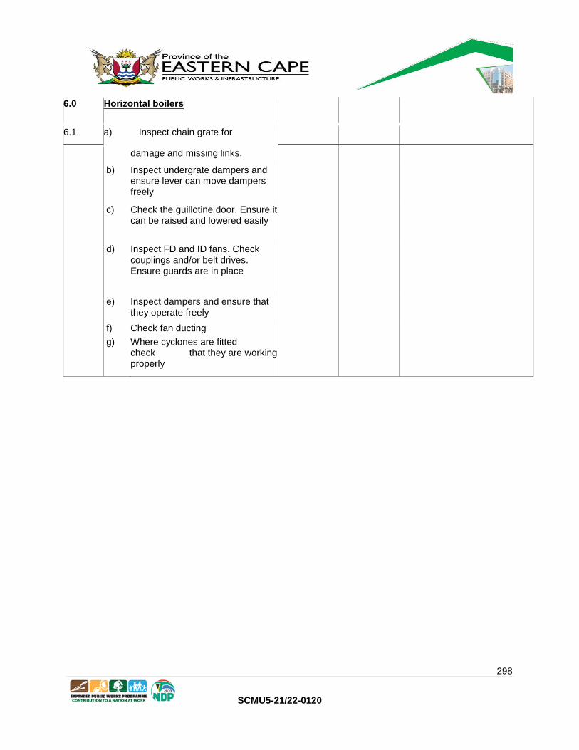
298
SCMU5-21/22-0120
6.0 Horizontal boilers
6.1 a) Inspect chain grate for
damage and missing links.
b) Inspect undergrate dampers and ensure lever can move dampers freely
c) Check the guillotine door. Ensure it can be raised and lowered easily
d) Inspect FD and ID fans. Check couplings and/or belt drives. Ensure guards are in place
e) Inspect dampers and ensure that they operate freely
f) Check fan ducting
g) Where cyclones are fitted check that they are working properly
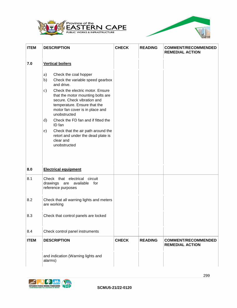
299
SCMU5-21/22-0120
ITEM DESCRIPTION CHECK READING COMMENT/RECOMMENDED REMEDIAL ACTION
7.0 Vertical boilers
a) Check the coal hopper
b) Check the variable speed gearbox
and drive.
c) Check the electric motor. Ensure
that the motor mounting bolts are
secure. Check vibration and
temperature. Ensure that the
motor fan cover is in place and
unobstructed
d) Check the FD fan and if fitted the
ID fan
e) Check that the air path around the
retort and under the dead plate is
clear and
unobstructed
8.0 Electrical equipment
8.1 Check that electrical circuit drawings are available for reference purposes
8.2 Check that all warning lights and meters are working
8.3 Check that control panels are locked
8.4 Check control panel instruments
ITEM DESCRIPTION CHECK READING COMMENT/RECOMMENDED REMEDIAL ACTION
and indication (Warning lights and alarms)

300
SCMU5-21/22-0120
8.5 Check that lighting is adequate
9.0 Water softening plant and chemical dosing
9.0 Check that the water softener installation is clean and tidy
9.1 Check that the water softener is operating correctly and that salt is available for regeneration
9.2 Check piping for leaks
9.3 Check the chemical dosing pump. Ensure that it is working properly and can deliver at the required pressure and flow
ITEM DESCRIPTION CHECK READING COMMENT/RECOMMENDED REMEDIAL ACTION
9.4 Ensure an adequate supply of WTW
chemicals (Order if stock is
below re-order level)
10.0 Blowdown valves
10.1 Check that the blowdown valve can be opened and closed easily
10.2 Check that the blowdown valve is not bypassing
11.0 Heavy Fuel Oil and Diesel Fired Boilers

301
SCMU5-21/22-0120
11.1 Check fuel lines for leaks
11.2 Inspect all fuel line valves
12.0 Burners
12.1 Remove the cover and clean the burner
13.0 Fuel Tanks
13.1 Inspect the fuel tanks
13.2 Ensure that all fuel spills are cleaned up properly
ITEM DESCRIPTION CHECK READING COMMENT/RECOMMEN DED REMEDIAL ACTION
13.3 Ensure that the bund area around the tanks is clean
13.4 Check that fuel tank filler caps are locked
13.5 Ensure that there is an adequate supply of fuel.
14.0 Fuel Transfer Pumps
14.1 Inspect fuel pump, motor and coupling for any problems
14.2 Inspect fuel strainer/filter and change-over and clean when necessary.
15.0 Daily Maintenance Tasks

302
SCMU5-21/22-0120
15.1 Blow down the water columns (Open
cocks slowly to prevent float damage)
Ensure level recovers quickly when drain cocks are closed.
15.2 Blow down the bottom of the boiler
15.3 Track boiler pressure and temperature to determine that it is keeping up with the load.
15.4 Take a stack temperature reading to determine how efficiently the boiler is working. (50oC-100oC above steam or water temperature)
15.5 Monitor water supply and condensate return temperatures.
15.6 Check furnace and observe flame for evidence of impingement and sooting.
15.7 Take water samples and ensure the water is clean and sediment free.
Notes:
1. Normal service components are to be included as part of the routine service
2. Faulty equipment must be reported and recommendations made for remedial action (see
schedules below)
3. Where electrical equipment is perceived to be faulty this must be reported (see schedules below)
4. Should components of the installation no longer comply with the latest regulations this must be
noted. (See schedules below)
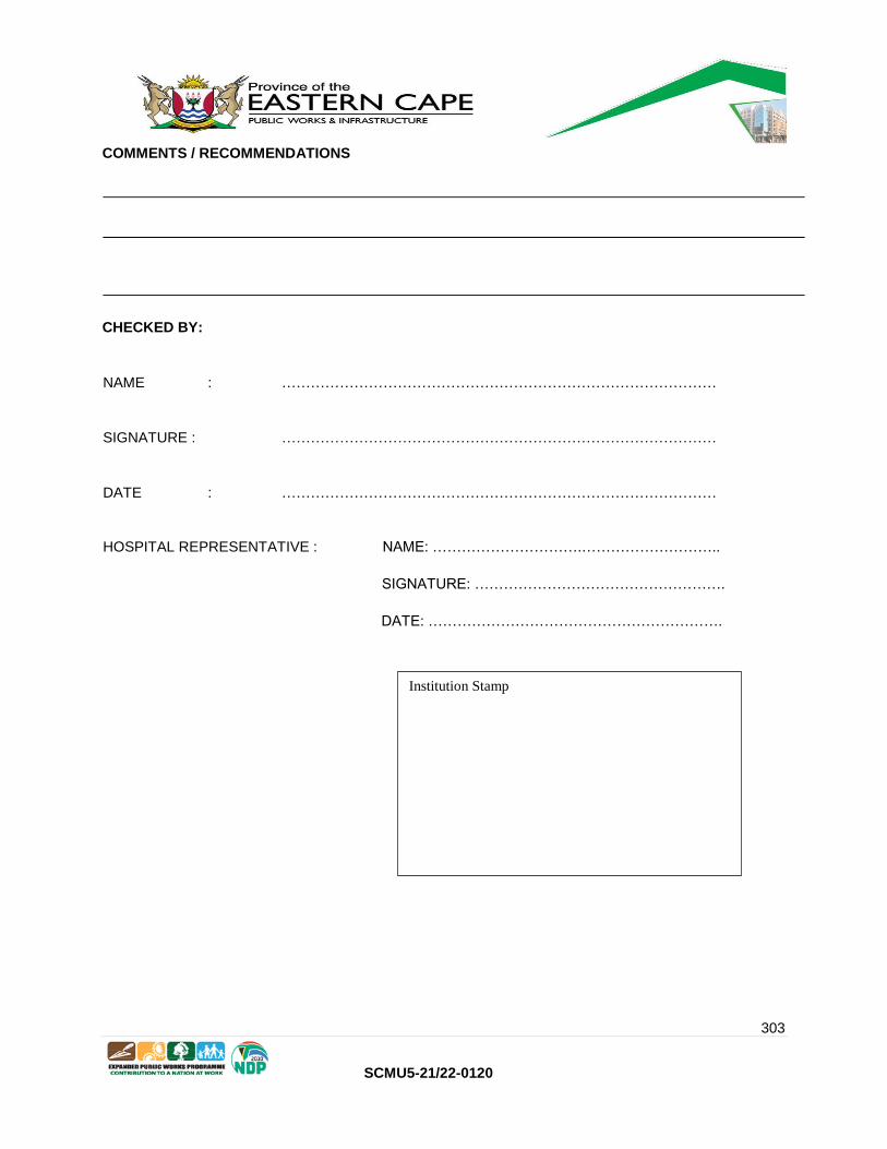
303
SCMU5-21/22-0120
COMMENTS / RECOMMENDATIONS
CHECKED BY:
NAME : ………………………………………………………………………………
SIGNATURE : ………………………………………………………………………………
DATE : ………………………………………………………………………………
HOSPITAL REPRESENTATIVE : NAME: ………………………….………………………..
SIGNATURE: …………………………………………….
DATE: …………………………………………………….
Institution Stamp

304
SCMU5-21/22-0120
C3.3: STEAM BOILER WEEKLY INSPECTIONS
Note:
Weekly inspections must be conducted by the boiler operator.
Weekly inspections will include daily inspections.
Results and findings must be entered in the boiler log book and signed by the relevant boiler operator.
The tasks listed is for a generic service regime. Where this Task List included below does not include
manufacture’s servicing specifications, the Original Equipment Manufacturer’s servicing specifications
must be added, as all services are to be carried out in accordance with the manufacture’s specification.
UNIT LOCATION MAKE OF UNIT
MODEL No. SERIAL NUMBER
ITEM DESCRIPTION CHECK READING COMMENT/RECOMMENDE D REMEDIAL ACTION
1.0 General
As per daily inspections
2.0 Piping and valves (Inside Boiler House)
2.1 As per daily inspections.
2.2 Check that all steam traps are in good working condition
2.3 Check and clean all strainers
2.4 Check all piping and manifolds for leaks
3.0 Boilers
3.1 As per daily inspections
3.2 Check hand hole and mud hole covers for leaks. Renew gaskets if necessary

305
SCMU5-21/22-0120
3.3 Inspect the coupling. Ensure that it is good condition and that all bolts are tight
3.4 Lubricate bearings at least once per week
3.5 Check the control panel. Gauges must be clean and legible. Control knobs must not be cracked or broken. Replace any missing levers or control knobs
3.6 Check that all wiring is clean and tidy and properly secured
ITEM DESCRIPTION CHECK READING
COMMENT/RECOMMENDE D REMEDIAL ACTION
4.0 Appurtenances
4.1 Pressure gauges
a) As per daily inspections
b) Check that the pressure gauges are properly supported. (Do not rely on the pressure gauge tubing to support the gauge)
4.2 Water gauges
a) As per daily inspections
4.3 Level controllers and pressure switches
4.1 a) As per daily inspections
4.2 Temperature gauges

306
SCMU5-21/22-0120
a) As per daily inspections
4.3 Safety valves
a) As per daily inspections
b) Use the proving lever and ensure that the safety valve opens easily.
4.4 Stokers and feeders
a) As per daily inspections
b) Lubricate chains and sprockets.
Check chain tension and adjust
if necessary
c) Check oil level in gearbox
d) Where V-belts are fitted ensure they are tensioned correctly and that the guards are in place
5.0 Horizontal boilers
a) As per daily inspections
b) Inspect front and rear side seal
and replace if necessary
c) Check all carbofrax blocks and
replace if necessary
d) Inspect undergrate dampers and ensure lever can move dampers freely

307
SCMU5-21/22-0120
ITEM DESCRIPTION CHECK READING
COMMENT/RECOMMENDE D REMEDIAL ACTION
e) Check air guide vanes
f) Ensure chain grate is tensioned
properly
g) Check the operation of the soot
blowers
h) Check the fire door davits
i) Open fire doors and check the
reversal chambers. They must be
free of soot and coal dust
j) Inspect ash removal door
k) Inspect FD and ID fans. Check
couplings and/or belt drives.
Ensure guards are in place
l) Where VSD’s are fitted they must
be tested through the
full range of operation
m) Check fan ducting
n) Check the boiler chimney and
chimney stay wires where
fitted
o) Where cyclones are fitted check that they are working properly
6.0 Vertical boilers
a) As per daily inspections
b) Check the variable speed gearbox and drive. Lubricate all points.
c) Check the V-belt tension and adjust if necessary
d) Check the retort tuyers and deadplate. (Replace if cracked or damaged.)
e) Check the fuseable plug
c) Check the chimney and chimney stay wires where fitted
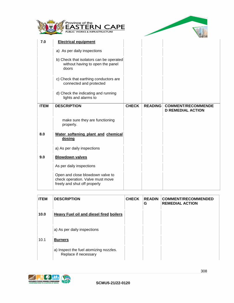
308
SCMU5-21/22-0120
7.0 Electrical equipment
a) As per daily inspections
b) Check that isolators can be operated without having to open the panel doors
c) Check that earthing conductors are connected and protected
d) Check the indicating and running lights and alarms to
ITEM DESCRIPTION CHECK READING COMMENT/RECOMMENDE D REMEDIAL ACTION
make sure they are functioning properly.
8.0 Water softening plant and chemical dosing
a) As per daily inspections
9.0 Blowdown valves
As per daily inspections
Open and close blowdown valve to check operation. Valve must move freely and shut off properly
ITEM DESCRIPTION CHECK READIN G
COMMENT/RECOMMENDED REMEDIAL ACTION
10.0 Heavy Fuel oil and diesel fired boilers
a) As per daily inspections
10.1 Burners
a) Inspect the fuel atomizing nozzles. Replace if necessary

309
SCMU5-21/22-0120
b) Clean the ignition rods
c) Clean the photo cell
11.0 Fuel Tanks
a) Inspect the fuel tanks
a) Clean and service fuel heaters if installed
b) Check the bund walls for cracks and holes
12.0 Fuel Transfer Pumps
12.1 Inspect fuel pump, motor and coupling for any problems
12.2 Inspect fuel strainer/filter and change-over and clean when necessary.
13.0 Maintenance Tasks
13.1 Blow down the water columns (Open
cocks slowly to prevent float damage)
Ensure level recovers quickly when
ITEM DESCRIPTION CHECK READIN G
COMMENT/RECOMMENDED REMEDIAL ACTION
drain cocks are closed.
13.2 Blow down the bottom of the boiler
13.3 Track boiler pressure and temperature to determine that it is keeping up with the load.
310
SCMU5-21/22-0120
13.4 Take a stack temperature reading to determine how efficiently the boiler is working. (50oC-100oC above steam or water temperature)
13.5 Monitor water supply and condensate return temperatures
13.6 Check furnace and observe flame for evidence of impingement and sooting.
13.7 Take water samples and ensure the water is clean and sediment free.
13.8 Conduct an evaporation test on the low water level controls to ensure proper operation. For boilers with burners ensure burner shut off at the low water point
13.9 Check the single point positioning system of the burner, if applicable, look for wear, slip and hysteresis.
13.10 Observe the operation of the modulating controls. While watching the pressure gauge ensure that the modulating controls are switching at the set points.
13.11 Pull out the flame scanner to ensure the burner shuts off at the prescribed time.
Notes:
1. Normal service components are to be included as part of the routine service
2. Faulty equipment must be reported and recommendations made for remedial action (see
schedules below)
3. Where electrical equipment is perceived to be faulty this must be reported (see schedules
below)

311
SCMU5-21/22-0120
4. Should components of the installation no longer comply with the latest regulations this must be
noted. (see schedules below)
COMMENTS / RECOMMENDATIONS
CHECKED BY:
NAME : ………………………………………………………………………………
SIGNATURE : ………………………………………………………………………………
DATE : ………………………………………………………………………………
HOSPITAL REPRESENTATIVE : NAME: ………………………….………………………..
SIGNATURE: …………………………………………….
DATE: …………………………………………………….
Institution Stamp

312
SCMU5-21/22-0120
C3.4: STEAM BOILER MONTHLY INSPECTIONS
Note:
Monthly inspections must be conducted by the Boiler Service Provider.
The Monthly Inspection will replace the Weekly inspection that falls in the same week, but will be done
by the Service Provider.
Results and findings must be entered in the boiler log book and signed by the relevant boiler operator.
The tasks listed is for a generic service regime. Where this Task List included below does not include
manufacture’s servicing specifications, the Original Equipment Manufacturer’s servicing specifications
must be added, as all services are to be carried out in accordance with the manufacture’s specification.
UNIT LOCATION MAKE OF UNIT
MODEL No. SERIAL NUMBER
ITEM DESCRIPTION CHECK READING
COMMENT/RECOMMENDED REMEDIAL ACTION
4.0 Appurtenances
4.1 Pressure gauges
a) As per daily inspections
b) Check that the pressure gauges are properly supported. (Do not rely on the pressure gauge tubing to support the gauge)
4.2 Water gauges
a) As per daily inspections
4.3 Level controllers and pressure switches
4.1 a) As per daily inspections
4.2 Temperature gauges
a) As per daily inspections

313
SCMU5-21/22-0120
4.3 Safety valves
a) As per daily inspections
b) Use the proving lever and ensure that the safety valve opens easily.
4.4 Stokers and feeders
a) As per daily inspections
b) Lubricate chains and sprockets.
Check chain tension and adjust
if necessary
c) Check oil level in gearbox
d) Where V-belts are fitted ensure they are tensioned correctly and that the guards are in place
5.0 Horizontal boilers
a) As per daily inspections
b) Inspect front and rear side seal
and replace if necessary
c) Check all carbofrax blocks and
replace if necessary
d) Inspect undergrate dampers and ensure lever can move

314
SCMU5-21/22-0120
ITEM DESCRIPTION CHECK READING COMMENT/RECOMMENDED REMEDIAL ACTION
dampers freely
e) Check air guide vanes
f) Ensure chain grate is tensioned
properly
g) Check the operation of the soot
blowers
h) Check the fire door davits
i) Open fire doors and check the
reversal chambers. They must be
free of soot and coal dust
j) Inspect ash removal door
k) Inspect FD and ID fans. Check
couplings and/or belt drives.
Ensure guards are in place
l) Where VSD’s are fitted they must
be tested through the
full range of operation
m) Check fan ducting
n) Check the boiler chimney and
chimney stay wires where
fitted
o) Where cyclones are fitted check that they are working properly
6.0 Vertical boilers
a) As per daily inspections
b) Check the variable speed gearbox and drive. Lubricate all points.
c) Check the V-belt tension and adjust if necessary
d) Check the retort tuyers and deadplate. (Replace if cracked or damaged.)
e) Check the fuseable plug

315
SCMU5-21/22-0120
c) Check the chimney and chimney stay wires where fitted
7.0 Electrical equipment
a) As per daily inspections
b) Check that isolators can be operated without having to open the panel doors
c) Check that earthing conductors are connected and protected
d) Check the indicating and
ITEM DESCRIPTION CHECK READING COMMENT/RECOMMENDED REMEDIAL ACTION
running lights and alarms to make sure they are functioning properly.
8.0 Water softening plant and chemical dosing
a) As per daily inspections
9.0 Blowdown valves
As per daily inspections
Open and close blowdown valve to check operation. Valve must move freely and shut off properly

316
SCMU5-21/22-0120
ITEM DESCRIPTION CHECK READING COMMENT/RECOMMENDED REMEDIAL ACTION
10.0 Heavy Fuel oil and diesel fired boilers
a) As per daily inspections
10.1 Burners
a) Inspect the fuel atomizing nozzles. Replace if necessary
b) Clean the ignition rods
c) Clean the photo cell
11.0 Fuel Tanks
a) Inspect the fuel tanks
a) Clean and service fuel heaters if installed
b) Check the bund walls for cracks and holes
12.0 Fuel Transfer Pumps
12.1 Inspect fuel pump, motor and coupling for any problems
12.2 Inspect fuel strainer/filter and change-over and clean when necessary.
13.0 Maintenance Tasks
13.1 Blow down the water columns (Open cocks slowly to prevent float damage)

317
SCMU5-21/22-0120
ITEM DESCRIPTION CHECK READING COMMENT/RECOMMENDED REMEDIAL ACTION
Ensure level recovers quickly when drain cocks are closed.
13.2 Blow down the bottom of the boiler
13.3 Track boiler pressure and temperature to determine that it is keeping up with the load.
13.4 Take a stack temperature reading to determine how efficiently the boiler is working. (50oC-100oC above steam or water temperature)
13.5 Monitor water supply and condensate return temperatures
13.6 Check furnace and observe flame for evidence of impingement and sooting.
13.7 Take water samples and ensure the water is clean and sediment free.
13.8 Conduct an evaporation test on the low water level controls to ensure proper operation. For boilers with burners ensure burner shut off at the low water point
13.9 Check the single point positioning system of the burner, if applicable, look for wear, slip and hysteresis.

318
SCMU5-21/22-0120
13.10 Observe the operation of the modulating controls. While watching the pressure gauge ensure that the modulating controls are switching at the set points.
13.11 Pull out the flame scanner to ensure the burner shuts off at the prescribed time.
Notes:
1. Normal service components are to be included as part of the routine service
2. Faulty equipment must be reported and recommendations made for remedial action (see
schedules below)
3. Where electrical equipment is perceived to be faulty this must be reported (see schedules
below)
4. Should components of the installation no longer comply with the latest regulations this must be
noted. (see schedules below)
COMMENTS / RECOMMENDATIONS
CHECKED BY:
NAME : ………………………………………………………………………………
SIGNATURE : ………………………………………………………………………………
DATE : ………………………………………………………………………………
HOSPITAL REPRESENTATIVE : NAME: ………………………….………………………..
SIGNATURE: …………………………………………….
DATE: …………………………………………………….
319
SCMU5-21/22-0120
C3.5: STEAM BOILER ANNUAL INSPECTIONS
Note:
Annual inspections must be conducted by a competent contractor.
The annual inspection will include all checks as listed hereunder.
Results and findings must be entered in the boiler log book and signed by the relevant contractor.
The tasks listed is for a generic service regime. Where this Task List included below does not include manufacture’s servicing specifications, the Original
Equipment Manufacturer’s servicing specifications must be added, as all services are to be carried out in accordance with the manufacture’s specification
UNIT LOCATION MAKE OF UNIT
MODEL No. SERIAL NUMBER
ITEM DESCRIPTION CHECK READING COMMENT/RECOMMENDE D REMEDIAL ACTION
1 General
1.1 Inspect boiler house to ensure housekeeping is being done. Floors, walls and windows must be clean and dust free.
1.2 Check that nothing is being stored near or against the boiler and causing obstruction.
Institution Stamp

320
SCMU5-21/22-0120
1.3 Boiler operators must have a clear unobstructed view of the pressure gauges.
1.4 Operators must be able to reach the gauge glass blow down valves.
1.5 Operators must have easy access to the control panel
1.6 Check that lighting in the boiler house is adequate
1.7 All covers for cable and pipe trenches must be in place
1.8 Provision must be made for the operator to access the crown and safety valves.
ITEM DESCRIPTION CHECK READING COMMENT/RECOMMENDED REMEDIAL ACTION
1.9 Hot wells must be fitted with level indicators positioned where the operators can read them from the firing floor, as well as high and low level alarms.
1.10 Check that firefighting equipment is available and in good operating condition
1.11 Check that all signage is in place
1.12 An enlarged copy of the relevant section of the Occupational Health and Safety Act and Regulations, framed and mounted a wall where it can easily be read

321
SCMU5-21/22-0120
1.13 Check that the boiler log books and service records are available and kept in a safe place
1.14 Check log book. If none, one to be provided
1.15 Record work done and findings in boiler log book
2 Piping and valves (Inside Boiler House)
2.1 Check all steam and feed water piping for leaks
2.2 Check all isolating valves for leaks
2.3 Check all insulation and cladding on steam and condensate lines
2.4 Check that all steam traps are in good working condition
2.5 Check and clean all strainers
2.6 Check that all pipes are correctly supported
2.7 Ensure that the hot well overflow piping is routed to a covered drain
2.8 Check that the hot well manhole is closed during normal boiler operation
2.9 Ensure that the blow off piping from the boiler safety valves

322
SCMU5-21/22-0120
ITEM DESCRIPTION CHECK READING COMMENT/RECOMMENDED REMEDIAL ACTION
extends at least 2m above the boiler house roof. (Blow off piping should not protrude out of the side of the building)
2.10 Check that the safety valves’ drain pipes lead down into the floor drains
3 Boilers
3.1 Inspect the boiler and ensure that it is
clean and wiped down at
least once per shift
3.2 Check that the insulation and cladding is in good condition
3.3 Inspect the boiler shell for leaks and other anomalies
3.4 Check hand hole and mud hole covers for leaks. Renew gaskets if necessary
3.5 Check the feed water pumps and piping. Ensure that there are no leaks
3.6 Check the feed water pump bearings. (Noise, vibration and temperature) Use bearing stethoscope, vibration pen infrared gun
3.7 Check that feed water isolation valves and reflux valves are in good working condition and not leaking
323
SCMU5-21/22-0120
3.8 Check that the feed water pumps meet the required duty
3.9 Inspect the coupling. Ensure that it is good condition and that all bolts are tight
3.10 Lubricate bearings at regular intervals
3.11 Check the control panel. Gauges must be clean and legible. Control knobs must not be cracked or broken. Replace any missing levers or control knobs
324
SCMU5-21/22-0120
ITEM DESCRIPTION CHECK READING COMMENT/RECOMMENDED REMEDIAL ACTION
3.12 Check that all wiring is clean and tidy and properly secured
3.13 Check all instrumentation and indication. (Warning lights and alarm bells on the controllers.)
3.14 Ensure that all gauges are reading accurately
3.15 Check all instrumentation and indication. (Warning lights and alarm bells on the controllers.)
4 Appurtenances
4.1 Pressure gauges
a) Check that all pressure gauges
have been calibrated
b) Pressure gauge glasses must be
clean and scratch free
c) Check that all pressure gauges
have white face
plates with black lettering
d) Check that the maximum working
pressure is marked with a red line
on the face plate. (Not on the
glass)
e) Check that the pressure gauge
stop cocks are in good working
condition
f) Check that the pressure gauges are properly supported. (Do not rely on the pressure gauge tubing to support the gauge)
4.2 Pressure gauges
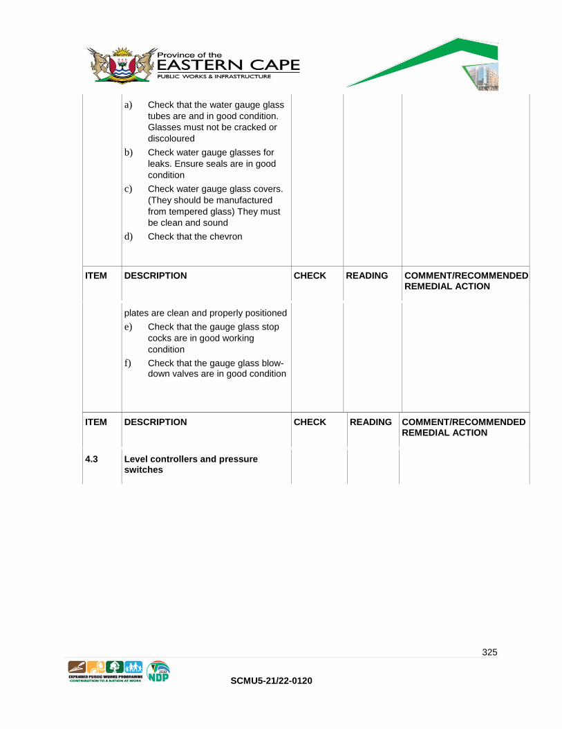
325
SCMU5-21/22-0120
ITEM DESCRIPTION CHECK READING COMMENT/RECOMMENDED REMEDIAL ACTION
4.3 Level controllers and pressure switches
a) Check that the water gauge glass
tubes are and in good condition.
Glasses must not be cracked or
discoloured
b) Check water gauge glasses for
leaks. Ensure seals are in good
condition
c) Check water gauge glass covers.
(They should be manufactured
from tempered glass) They must
be clean and sound
d) Check that the chevron
ITEM DESCRIPTION CHECK READING COMMENT/RECOMMENDED REMEDIAL ACTION
plates are clean and properly positioned
e) Check that the gauge glass stop
cocks are in good working
condition
f) Check that the gauge glass blow-down valves are in good condition

326
SCMU5-21/22-0120
a) Check that the level controllers are
working correctly
b) With the covers removed operate
the switches manually to ensure
that they operate freely
c) Check the level controller floats.
Ensure that they move smoothly
inside the tubes
d) Check that the floats trigger the
switches at the correct height
e) Check the level controller blow down valves. They must open and close freely
4.4 Temperature gauges
a) Check that the temperature
gauges have been calibrated
b) Gauges should have white face plates with black lettering
4.5 Safety valves
a) Check that the boiler is fitted with
at least two safety valves. (A
single valve with dual pots is
acceptable)
b) Safety valves covers must be in place and locked
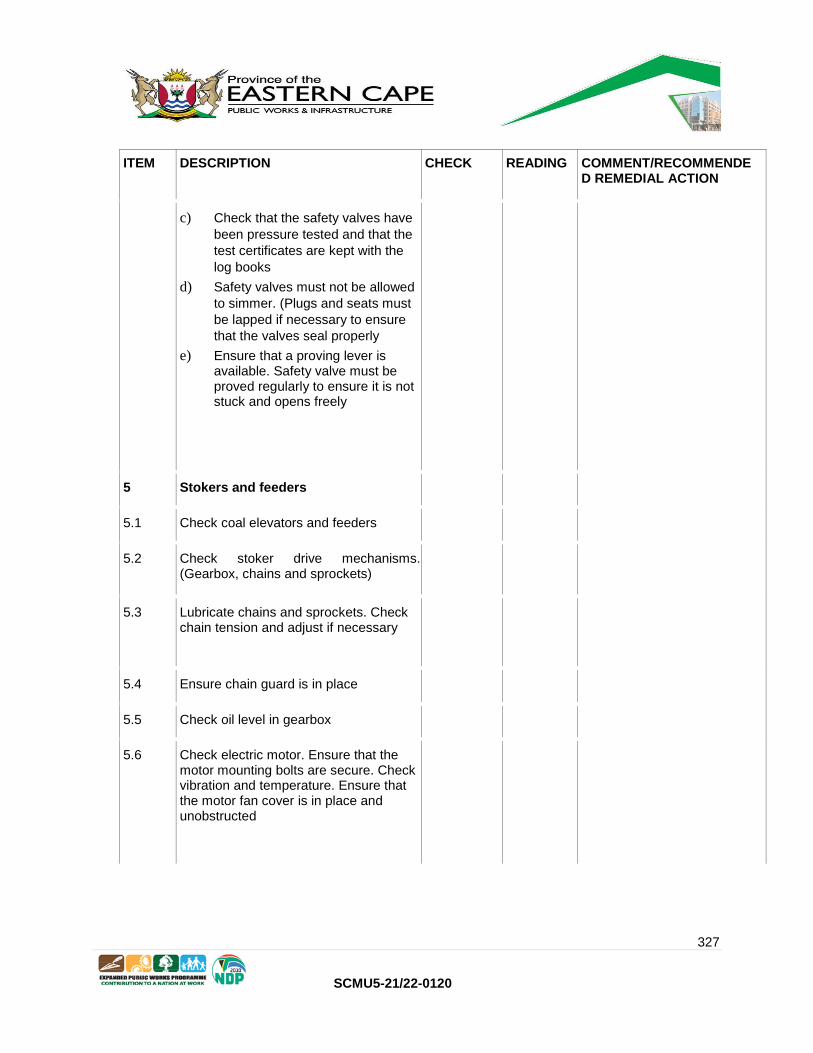
327
SCMU5-21/22-0120
ITEM DESCRIPTION CHECK READING COMMENT/RECOMMENDE D REMEDIAL ACTION
c) Check that the safety valves have
been pressure tested and that the
test certificates are kept with the
log books
d) Safety valves must not be allowed
to simmer. (Plugs and seats must
be lapped if necessary to ensure
that the valves seal properly
e) Ensure that a proving lever is available. Safety valve must be proved regularly to ensure it is not stuck and opens freely
5 Stokers and feeders
5.1 Check coal elevators and feeders
5.2 Check stoker drive mechanisms. (Gearbox, chains and sprockets)
5.3 Lubricate chains and sprockets. Check chain tension and adjust if necessary
5.4 Ensure chain guard is in place
5.5 Check oil level in gearbox
5.6 Check electric motor. Ensure that the motor mounting bolts are secure. Check vibration and temperature. Ensure that the motor fan cover is in place and unobstructed

328
SCMU5-21/22-0120
5.7 Where V-belts are fitted ensure they are tensioned correctly and that the guards are in place
6 Horizontal boilers
a) Inspect chain grate for damage
and missing links.
Check link pins
b) Inspect front and rear side seal
and replace if necessary
c) Check all carbofrax blocks and
replace if necessary
d) Inspect undergrate dampers and
ensure lever can move dampers
freely
e) Check air guide vanes

329
SCMU5-21/22-0120
f) Ensure chain grate is tensioned
properly
g) Check condition of tubes. (Fire
side) Wire brush if necessary
h) Inspect wearing strips and replace
if necessary
i) Check sliding plates (Drive side
and non-drive side)
j) Check front shaft, grate sprockets
and bosses
k) Check rear roller and shaft
l) Check the guillotine door. Ensure it
can be raised and lowered easily
m) Check all boiler internal
refractories including the ignition
arch
n) Check the operation of the soot
blowers
o) Check the fire door davits
p) Open fire doors and check the
reversal chambers. They must be
free of soot and coal dust
q) Inspect ash removal door
r) Inspect FD and ID fans. Check
couplings and/or belt drives.
Ensure guards are in place
s) Inspect dampers and ensure that
they operate freely
t) Where VSD’s are fitted they must
be tested through the
full range of operation
u) Check fan ducting
v) Check the boiler chimney and
chimney stay wires where fitted
w) Where cyclones are fitted check that they are working properly

330
SCMU5-21/22-0120
7 Vertical boilers
a) Check the coal hopper
b) Check the variable speed gearbox and drive. Check lubrication

331
SCMU5-21/22-0120
ITEM DESCRIPTION CHECK READING COMMENT/RECOMMENDE D REMEDIAL ACTION
c) Check the electric motor. Ensure
that the motor mounting bolts are
secure. Check vibration and
temperature. Ensure that the
motor fan cover is in place and
unobstructed
d) Check the V-belt tension and
adjust if necessary
e) Check the FD fan and if fitted the
ID fan
f) Check the retort tuyers and
deadplate. (Replace if cracked or
damaged.)
g) Check that the air path around the
retort and under the deadplate is
clear and unobstructed
h) Check the fuseable plug
i) Check the chimney and chimney
stay wires where
fitted
8 Electrical equipment
8.1 Check that electrical circuit drawings are available for reference purposes
8.2 Check that all warning lights and meters are working
8.3 Check that control panels are locked
8.4 Check that isolators can be operated without having to open the panel doors
8.5 Check that all wiring is clean and tidy

332
SCMU5-21/22-0120
8.6 Check that cables are protected where there is danger of them being damaged
8.7 Check that earthing conductors are connected and protected
8.8 Check control panel instruments and indication (Warning lights and alarms)
8.9 Check that lighting is adequate
ITEM DESCRIPTION CHECK READING COMMENT/RECOMMENDE D REMEDIAL ACTION
9 Water softening plant and chemical dosing
9.1 Check that the water softener installation is clean and tidy
9.2 Check that the water softener is operating correctly and that salt is available for regeneration
9.3 Check piping for leaks
9.4 Check the chemical dosing pump. Ensure that it is working properly and can deliver at the required pressure and flow
9.5 Ensure an adequate supply of chemicals
10 Blowdown valves
10.1 Check that the blowdown valve can be opened and closed easily

333
SCMU5-21/22-0120
10.2 Check that the blowdown valve is not bypassing
11.0 Boiler Test
11.1 Test boiler operation (Functioning of all systems
11.2 Test flue gasses. (Residual oxygen, CO and NOx) Set air/fuel ratio for optimum combustion.
11.3 Reset combustion using a combustion analyzer if necessary.
12 Heavy Fuel oil and diesel fired boilers
12.1 Service burners at intervals as required by the manufacturer, but at least every six months
12.2 Check the fuel consumption. (Compare with manufacturers fuel consumption figures)
12.3 Where there is a large discrepancy, check the operation of the air damper and ensure that the atomizing nozzles are the right size
12.4 Replace fuel filters
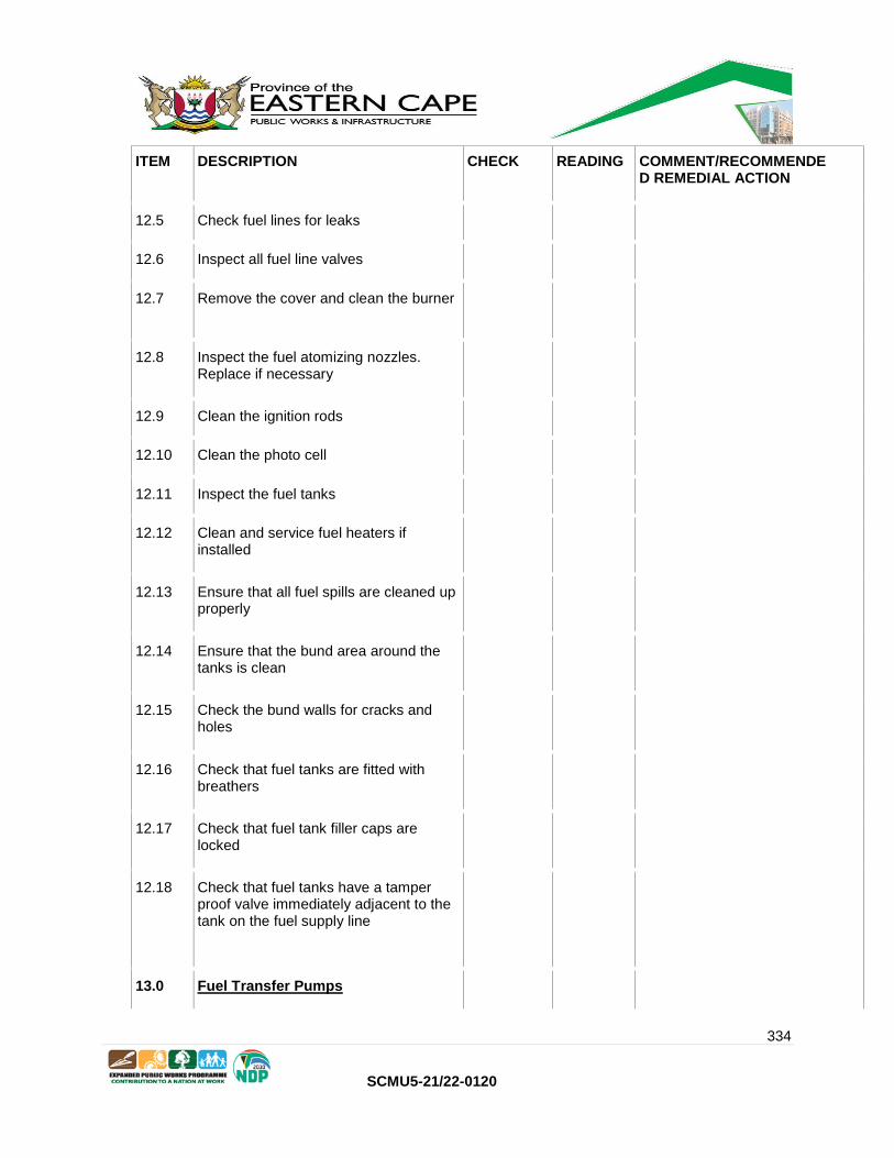
334
SCMU5-21/22-0120
ITEM DESCRIPTION CHECK READING COMMENT/RECOMMENDE D REMEDIAL ACTION
12.5 Check fuel lines for leaks
12.6 Inspect all fuel line valves
12.7 Remove the cover and clean the burner
12.8 Inspect the fuel atomizing nozzles. Replace if necessary
12.9 Clean the ignition rods
12.10 Clean the photo cell
12.11 Inspect the fuel tanks
12.12 Clean and service fuel heaters if installed
12.13 Ensure that all fuel spills are cleaned up properly
12.14 Ensure that the bund area around the tanks is clean
12.15 Check the bund walls for cracks and holes
12.16 Check that fuel tanks are fitted with breathers
12.17 Check that fuel tank filler caps are locked
12.18 Check that fuel tanks have a tamper proof valve immediately adjacent to the tank on the fuel supply line
13.0 Fuel Transfer Pumps
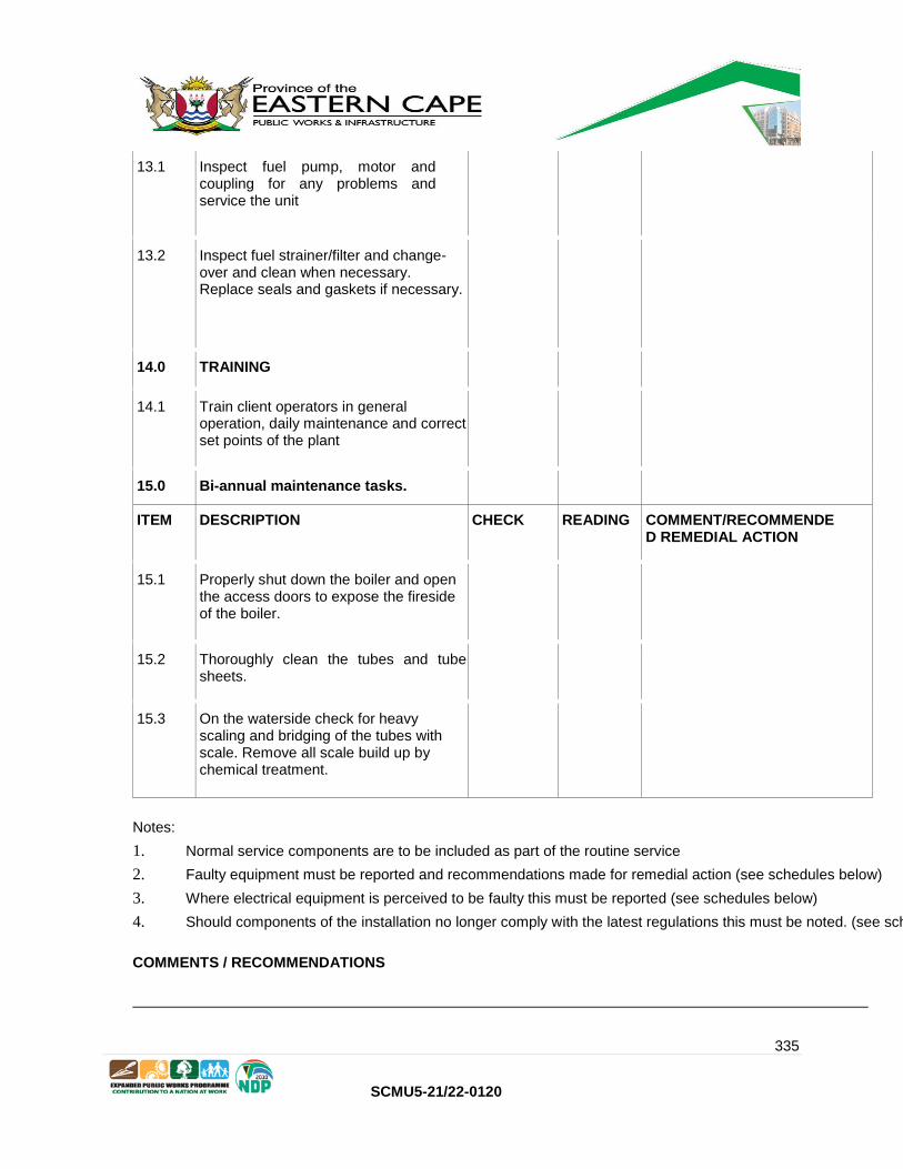
335
SCMU5-21/22-0120
13.1 Inspect fuel pump, motor and coupling for any problems and service the unit
13.2 Inspect fuel strainer/filter and change-over and clean when necessary. Replace seals and gaskets if necessary.
14.0 TRAINING
14.1 Train client operators in general operation, daily maintenance and correct set points of the plant
15.0 Bi-annual maintenance tasks.
ITEM DESCRIPTION CHECK READING COMMENT/RECOMMENDE D REMEDIAL ACTION
15.1 Properly shut down the boiler and open the access doors to expose the fireside of the boiler.
15.2 Thoroughly clean the tubes and tube sheets.
15.3 On the waterside check for heavy scaling and bridging of the tubes with scale. Remove all scale build up by chemical treatment.
Notes:
1. Normal service components are to be included as part of the routine service
2. Faulty equipment must be reported and recommendations made for remedial action (see schedules below)
3. Where electrical equipment is perceived to be faulty this must be reported (see schedules below)
4. Should components of the installation no longer comply with the latest regulations this must be noted. (see schedules below)
COMMENTS / RECOMMENDATIONS

336
SCMU5-21/22-0120
Annual Inspection Sheet
CHECKED BY:
NAME : ………………………………………………………………………………
SIGNATURE : ………………………………………………………………………………
DATE : ………………………………………………………………………………
HOSPITAL REPRESENTATIVE: NAME: ………………………….………………………..
SIGNATURE: …………………………………………….
DATE: …………………………………………………….
Institution Stamp

337
SCMU5-21/22-0120
C3.6 STEAM BOILER STATUTORY INSPECTIONS
Note:
Statutory inspections must be conducted by a competent contractor
The statutory inspection requires that all the work required for a normal annual inspection
be done first, followed by the task listed for the Statutory Inspection as listed hereunder.
All NDT (Non Destructive Testing) and pressure tests must be witnessed by an approved
Independent Inspection Authority.
The tasks listed is for a generic service regime. Where this Task List included below does not
include manufacture’s servicing specifications, the Original Equipment Manufacturer’s servicing
specifications must be added, as all services are to be carried out in accordance with the
manufacture’s specification
After recommissioning the employer may call for a functionality test to be performed on the boiler.
UNIT LOCATION
MAKE OF UNIT
MODEL No. SERIAL NUMBER
ITEM DESCRIPTION CHECK
READING COMMENT/RECOMMENDED REMEDIAL ACTION
1 General
1.1 Check log book. If none one to be provided
1.2 Record work done and findings in boiler log book
1.3 Place a Copy of the Statutory Inspection Certificate in the back of the Log Book

338
SCMU5-21/22-0120
2.0 Statutory Inspection (Required to be done 3 yearly in terms of the OHS Act and Regulations) (An authorized third party inspection authority should witness and sign off this inspection)
2.1 Remove all insulation and cladding
2.2 Chemically clean the water side of the boiler to remove all scale
2.3 Mechanically clean the fire side of the boiler to remove scale, soot and slag
2.4 Check the boiler shell internally and externally for corrosion. (Particular attention to be paid to the area around the ‘boiling line’ on the
ITEM DESCRIPTION CHECK
READING COMMENT/RECOMMENDE D REMEDIAL ACTION
inside of the shell
2.5 Check the shell for bulging
2.6 Check the tubes and tube plates for corrosion
2.7 Check tubes for hogging and sagging
2.8 Check the tube ends for leaks. Reexpand if necessary
2.9 Carry out thickness tests on the shell and tubes
2.10 Check all shell welds. (Dye penetrant or MPI test for cracks)

339
SCMU5-21/22-0120
2.11 Inspect the ligaments between the tubes for cracks. (Dye penetrant)
2.12 Check the stay tubes and stay rod welds
2.13 Check the flue for flame erosion and pitting
2.14 Check the flue for distortion
2.15 Check the flue welds for cracks
2.16 Blank off all openings into the pressure envelope and conduct pressure tests
2.17 Service and test all appurtenances
2.18 Check all alarms and sirens are working properly
2.19 Grit blast and paint the outside of the boiler shell if necessary
2.20 Replace all insulation and cladding
2.21 Recommission boiler
2.22 Test boiler operation
2.23 Test flue gasses. (Residual
oxygen, NOX and CO). Set air/fuel
ratio for
optimum combustion
3.0 If any welding needs to be done on the boiler the repair must be authorised and managed by an appropriately qualified Certificated Engineer and the Boiler must be recertified afterwards.
Notes:
1. Normal service components are to be included as part of the routine service

340
SCMU5-21/22-0120
2. Faulty equipment must be reported and recommendations made for remedial action (see
schedules below)
3. Where electrical equipment is perceived to be faulty this must be reported (see schedules
below)
4. Should components of the installation no longer comply with the latest regulations this
must be noted. (see schedules below)
COMMENTS / RECOMMENDATIONS
CHECKED BY:
NAME : ………………………………………………………………………………
SIGNATURE : ………………………………………………………………………………
DATE : ………………………………………………………………………………
HOSPITAL REPRESENTATIVE : NAME: ………………………….………………………..
SIGNATURE: …………………………………………….
DATE: …………………………………………………….
Institution Stamp
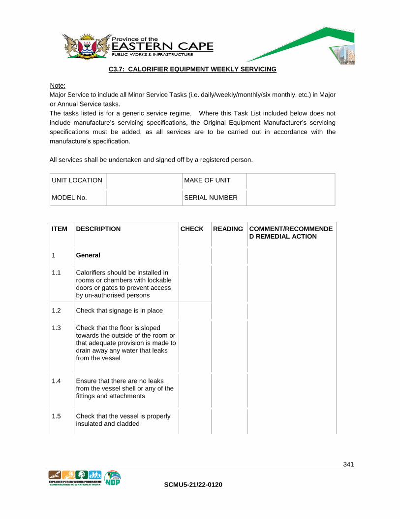
341
SCMU5-21/22-0120
C3.7: CALORIFIER EQUIPMENT WEEKLY SERVICING
Note:
Major Service to include all Minor Service Tasks (i.e. daily/weekly/monthly/six monthly, etc.) in Major
or Annual Service tasks.
The tasks listed is for a generic service regime. Where this Task List included below does not
include manufacture’s servicing specifications, the Original Equipment Manufacturer’s servicing
specifications must be added, as all services are to be carried out in accordance with the
manufacture’s specification.
All services shall be undertaken and signed off by a registered person.
UNIT LOCATION MAKE OF UNIT
MODEL No. SERIAL NUMBER
ITEM DESCRIPTION CHECK READING COMMENT/RECOMMENDE D REMEDIAL ACTION
1 General
1.1 Calorifiers should be installed in rooms or chambers with lockable doors or gates to prevent access by un-authorised persons
1.2 Check that signage is in place
1.3 Check that the floor is sloped towards the outside of the room or that adequate provision is made to drain away any water that leaks from the vessel
1.4 Ensure that there are no leaks from the vessel shell or any of the fittings and attachments
1.5 Check that the vessel is properly insulated and cladded

342
SCMU5-21/22-0120
1.6 Check that the vessel drain pipe is lead into a suitable channel or drain
1.7 Check that a safety valve is fitted to the vessel and that the safety valve discharge pipe lead into a suitable channel or drain
1.8 Remove the inspection opening cover
1.9 Check that the temperature gauge is in good condition and reading correctly
1.10 Where pressure gauges are fitted,
ITEM DESCRIPTION CHECK READING COMMENT/RECOMMENDE D REMEDIAL ACTION
ensure that they are in good condition and reading correctly
1.11 Check the fusible plug. (If fitted)
1.12 Check that adequate lighting is provided
1.13 Where the valves on the calorifiers are pneumatically controlled the valves, pressure regulators and stop cocks must be inspected to ensure that they are in good condition and working properly
2 Steam Calorifiers
2.1 Check the condensate line valves from the separator

343
SCMU5-21/22-0120
2.2 Check the condensate line strainer and sight glass after the steam line separator
2.3 Check the main steam valve
2.4 Check and test the high limit protection unit
2.5 Check and test the high limit cutout unit shuttle valve and trigger
2.6 Check and test the temperature control valve
2.7 Check and test the fail-safe actuator unit
2.8 Check and test the high limit temperature sensor
2.9 Check and test the normal temperature sensor and adjustment screw
2.10 Where the temperature sensors are mounted in pockets or thermowells ensure that they are filled with the correct fluid. (Refer to the OEM manuals)
2.11 Check all the capillary tubes
2.12 Check and clean out the strainer on the condensate return line
2.13 Check the reflux valve on the condensate return line

344
SCMU5-21/22-0120
ITEM DESCRIPTION CHECK READING COMMENT/RECOMMENDED REMEDIAL ACTION
2.14 Check the sight glass on the condensate return line
2.15 Check the shut-off valve on the condensate return line
3 Electric Calorifiers
3.1 Check that there is a wiring diagram inside the electrical control panel
3.2 Check that all electrical wiring is clean, tidy and properly secured
3.3 Check that the electrical panel is a lockable unit and that the mains isolator can be operated without having to open the door
3.4 Check that the panel door can only be opened when the isolator is in the off position
3.5 Check that there is a voltmeter mounted in the door panel
3.6 Check that there is an ammeter for each phase mounted in the door panel. (Where there is only one ammeter check that there is a selector switch provided to switch between phases.)
3.7 Check that each element has its own circuit breaker
3.8 Check that all the heating elements have the same rating

345
SCMU5-21/22-0120
3.9 Check that the heating elements are covered with protective caps
3.10 Check that the heating elements are wired to balance the load on the phases
3.11 Where timers are fitted check and ensure that they are working correctly
3.12 Check that the contactors are clean
3.13 Where the thermostat is mounted in a pocket or thermowell ensure that it is filled with the correct non corrosive fluid. (Refer to the OEM
ITEM DESCRIPTION CHECK READING COMMENT/RECOMMENDE D REMEDIAL ACTION
manual)
3.14 Where indication and warning lamps are provide check that they are all in working condition
3.15 Where a PLC is used to control the temperature. The controller must be tested through the full temperature range and the set temperatures checked to ensure they hold steady

346
SCMU5-21/22-0120
4 Hot water pipes, support structures, gantries and bridges
4.1 Check hot water lines for leaks
4.2 Check all valves are operating correctly
4.3 Check re-circulating pump/s are running
4.4 Check all pipes are properly supported
4.5 Check all insulation is in good condition
4.6 Check all hanger brackets and replace where necessary
4.6 Where people are working at height ensure that scaffolding and ladders are properly certified and that safety harnesses are being used
4.7 Check all structures for corrosion, particularly at the bases
4.8 Remove rust and repair any corroded sections of structural steelwork
5 TRAINING
5.1 Train client operators in general operation, daily maintenance and correct set points of the plant
Notes:
1. Normal service components are to be included as part of the routine service
2. Faulty equipment must be reported and recommendations made for remedial action (see
schedules below)
347
SCMU5-21/22-0120
3. Where electrical equipment is perceived to be faulty this must be reported (see schedules
below)
4. Should components of the installation no longer comply with the latest regulations this
must be noted. (see schedules below)
COMMENTS / RECOMMENDATIONS
CHECKED BY:
NAME : ………………………………………………………………………………
SIGNATURE : ………………………………………………………………………………
DATE : ………………………………………………………………………………
HOSPITAL REPRESENTATIVE: NAME: ………………………….………………………..
SIGNATURE: …………………………………………….
DATE: …………………………………………………….
Institution Stamp

348
SCMU5-21/22-0120
C3.8: CALORIFIER EQUIPMENT ANNUAL SERVICING
Note:
Major Service (Annual Inspection) to include all Minor Service Tasks (i.e. daily/weekly/monthly/six
monthly, etc.) as well.
The tasks listed is for a generic service regime. Where this Task List included below does not
include manufacture’s servicing specifications, the Original Equipment Manufacturer’s servicing
specifications must be added, as all services are to be carried out in accordance with the
manufacture’s specification.
All services shall be undertaken and signed off by a registered person.
UNIT LOCATION MAKE OF UNIT
MODEL No. SERIAL NUMBER
ITEM DESCRIPTION CHECK
READING COMMENT/RECOMMENDE D REMEDIAL ACTION
1 General
1.1 Perform tasks from weekly service sheet.
1.2 Remove the inspection opening cover
1.3 Check that the inside surfaces are free of scale and corrosion
1.4 Check anodes and replace if necessary
1.5 Check and calibrate all gauges.
1.6 Check and service safety valves
1.7 Check the fusible plug. (If fitted)
1.8 If pneumatically controlled valves are installed, service them.
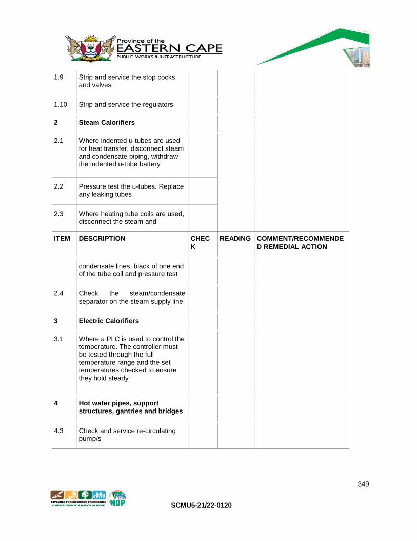
349
SCMU5-21/22-0120
1.9 Strip and service the stop cocks and valves
1.10 Strip and service the regulators
2 Steam Calorifiers
2.1 Where indented u-tubes are used for heat transfer, disconnect steam and condensate piping, withdraw the indented u-tube battery
2.2 Pressure test the u-tubes. Replace any leaking tubes
2.3 Where heating tube coils are used, disconnect the steam and
ITEM DESCRIPTION CHECK
READING COMMENT/RECOMMENDE D REMEDIAL ACTION
condensate lines, black of one end of the tube coil and pressure test
2.4 Check the steam/condensate separator on the steam supply line
3 Electric Calorifiers
3.1 Where a PLC is used to control the temperature. The controller must be tested through the full temperature range and the set temperatures checked to ensure they hold steady
4 Hot water pipes, support structures, gantries and bridges
4.3 Check and service re-circulating pump/s

350
SCMU5-21/22-0120
Notes:
1. Normal service components are to be included as part of the routine service
2. Faulty equipment must be reported and recommendations made for remedial action (see
schedules below)
3. Where electrical equipment is perceived to be faulty this must be reported (see schedules
below)
4. Should components of the installation no longer comply with the latest regulations this
must be noted. (see schedules below)
COMMENTS / RECOMMENDATIONS
CHECKED BY:
NAME : ………………………………………………………………………………
SIGNATURE : ………………………………………………………………………………
DATE : ………………………………………………………………………………
HOSPITAL REPRESENTATIVE: NAME: ………………………….………………………..
SIGNATURE: …………………………………………….
DATE: …………………………………………………….
Institution Stamp

351
SCMU5-21/22-0120
PART C4: SITE INFORMATION

352
SCMU5-21/22-0120
INSTITUTION No. of
Boilers
Boiler capacity
kg/hr Manufacturer
Fuel
Source
Frontier Hospital
2 2500 John Thompson Coal
Komani Hospital
3 8000 John Thompson Coal

353
SCMU5-21/22-0120
Facility Name Location Type of
Calorifier Make Model
Vessel Volume
Power (Kw)
Condition Value
Condition Priority
Komani Psychiatric Hospital
Ward 02 Steam Royles 28.09.11 2m3 Good Maintain
Komani Psychiatric Hospital
Ward 14 Steam Zululand steam 2m3 Good Maintain
Komani Psychiatric Hospital
Ward 10 Steam Royles 06.09.11 2m3 Good Maintain
Komani Psychiatric Hospital
Ward C3 Steam Royles 06.09.11 2m3 Good Maintain
Komani Psychiatric Hospital
Ward 01 Steam Zululand steam 2005 95 Good Maintain
Komani Psychiatric Hospital
Ward 12 Steam Royles 28.09.11 2m3 Good Maintain
Komani Psychiatric Hospital
Ward 11 Steam Zululand steam 2005 95 Good Maintain
Komani Psychiatric Hospital
Ward 9 Steam Royles 28.09.11 2m3 Good Maintain
Komani Psychiatric Hospital
Ward 04 Steam Royles 28.09.11 2m3 Good Maintain
Komani Psychiatric Hospital
Ward 03 Steam Royles 800 0.8m3 Good Maintain
Komani Psychiatric Hospital
Ward K Steam Royles 06.09.11 2m3 Good Maintain
Komani Psychiatric Hospital
Ward 13 Steam Royles 06.09.11 2m3 Good Facility Loss
Komani Psychiatric Hospital
Ward 16 Steam Zululand steam 2004 2m3 Good Maintain
Komani Psychiatric Hospital
Ward 5 and 6
Steam Zululand steam 2m3 Good Maintain
Komani Psychiatric Hospital
ward 15 Steam zululand steam 2004 2m3 Good Maintain
Komani Psychiatric Hospital
Ward 7 Steam Royles 06.08.11 2m3 Good Maintain
Komani Psychiatric Hospital
Main Kitchen
Steam Abeco 30/5/97 0.01m3 Good Maintain

354
SCMU5-21/22-0120
INSTITUTION No. of Boilers
Boiler capacity kg/hr
Manufacturer Fuel Source
Bhisho Hospital 3 2500 John Thompson
Coal
Butterworth Hospital 2 1800 John Thompson
Coal
Frere 2 4000 John Thompson
HFO
7

355
SCMU5-21/22-0120
Facility Name Location Type of
Calorifier Serial No Make Model
Vessel
Volume Power (Kw)
Condition
Value
Bhisho Hospital
Peads
ward
building
Steam No
nameplate No nameplate
No
nameplate
0,008 cubic
metres -
assumption
1200 kPa Poor
Bhisho Hospital Nursing
home
Steam No
nameplate
No nameplate No
nameplate
2300 cubic
metres-
assumption
400 kW -
assumption
Poor
Bhisho Hospital Nursing
home
Steam F7857B Heat Transfer
Engineering
Heat
Transfer
Engineering
2500 cubic
metres
400 kPa Poor
Bhisho Hospital
Maternity
and
Admin
building
Steam No
nameplate No nameplate
No
nameplate
2 300 cubic
metres
assumption
400 kPa-
assumption Poor
Bhisho Hospital Theatre Steam No
nameplate
No nameplate No
nameplate
1500 litres 350 kPa Poor
Bhisho Hospital Thaetre Steam No
nameplate
No nameplate No
nameplate
720 litres -
assumption
350 kPa -
assumption
Poor
Bhisho Hospital Ward 1
and ward
2 building
Steam 1571 Medical Fluid
Industries
Medical
Fluid
Industries
0,008 cubic
metres
1200 kPa Poor
Butterworth
Hospital
Plant
room
Steam None None None Not known Not known Unaccepta
ble
Frere Hospital B3 -B8 Steam ECC158 EAST CAPE
COMBUSTION
ECC 1600 Litres 500 kPa Good
Frere Hospital NTB B
SIDE
Steam F7857C Heat Transfer
Engineering
H. TRF. E 2 500 cubic
meter
400 kPa Good
Frere Hospital G5 Steam SB0350 720 Litres 350 kPa Good
Frere Hospital G3 Steam ECC168 EAST CAPE
COMBUSTION
ECC 1600 Litres 500 kPa Good
Frere Hospital G4 Steam SB0953 MULTI SERVICE
CONTRACTOR MSC
720 Litres -
assumptions
350 kPa -
assumptions Good
Frere Hospital Plaster
room
Steam 2633 MULTI SERVICE
CONTRACTORS
MSC 720 Litres 350 kPa Good
Frere Hospital NTB C
SIDE Steam 1888 B
HEAT
TRANSFER
ENGINEERING
H. TRF. E 10 cubic
meter
150 kPa -
steam
powered
Good
Frere Hospital B2 Steam 2635 Multi Servhce
Contractors
MSC 720 Litres 350 kPa -
steam
powered
Good
Frere Hospital MAIN
KITCHEN Steam ECC166
East Cape
Combustion ECC 1600 Litres 500 kPa Good

356
SCMU5-21/22-0120
Frere Hospital C Wards Steam ECC167 East Cape
Combustion
ECC 1600 Litres 500 kPa -
steam
powered
Good
Frere Hospital C Wards Steam ECC160 East Cape
Combustion ECC 1600 Litres
500 kPa -
steam
powered
Good
Frere Hospital B3 - B8 Steam ECC159 EAST CAPE
COMBUSTION
ECC 1600 Litres 500 kPa-
steam
powered
Good
Frere Hospital Day Ward Steam 2631 MULTI SERVICE
CONTRACTOR
MSC 720 Litres 350 kPa Good
Frere Hospital J BLOCK Steam 2636 MULT SERVICE
CONTRACT
MSC 1500 Litres 350 kPa-
steam
powered
Good


