

Testing for a shorted output transistor.
If on the front panel there is an LED for one of the channels that is brightly lit,
continuously ,when the unit is on and running, and you are not getting the correct
output signal. It is possible you have a blown output transistor.
1. Remove the input signal and short all three pins of the input connector
together. If the unit still has the same LED indicators proceed to step two.
2. Remove the top cover from the unit. Once the top cover is removed. Power
the unit on again, while observing the main board.
a. When powered on the LEDs E101 and E201 should light for about 3
seconds and then go out when you hear a relay click. This will not
happen on a unit that has a blown output transistor. When you hear the
relay click E102 or E202 will then light. And the corresponding LED
E101/201 will stay lit as well. Whichever channel has the LEDs lit is
the one with the blown or shorted output transistor.
b. The channel with the blown output transistor will need to have it’s
output boards repaired or replaced.
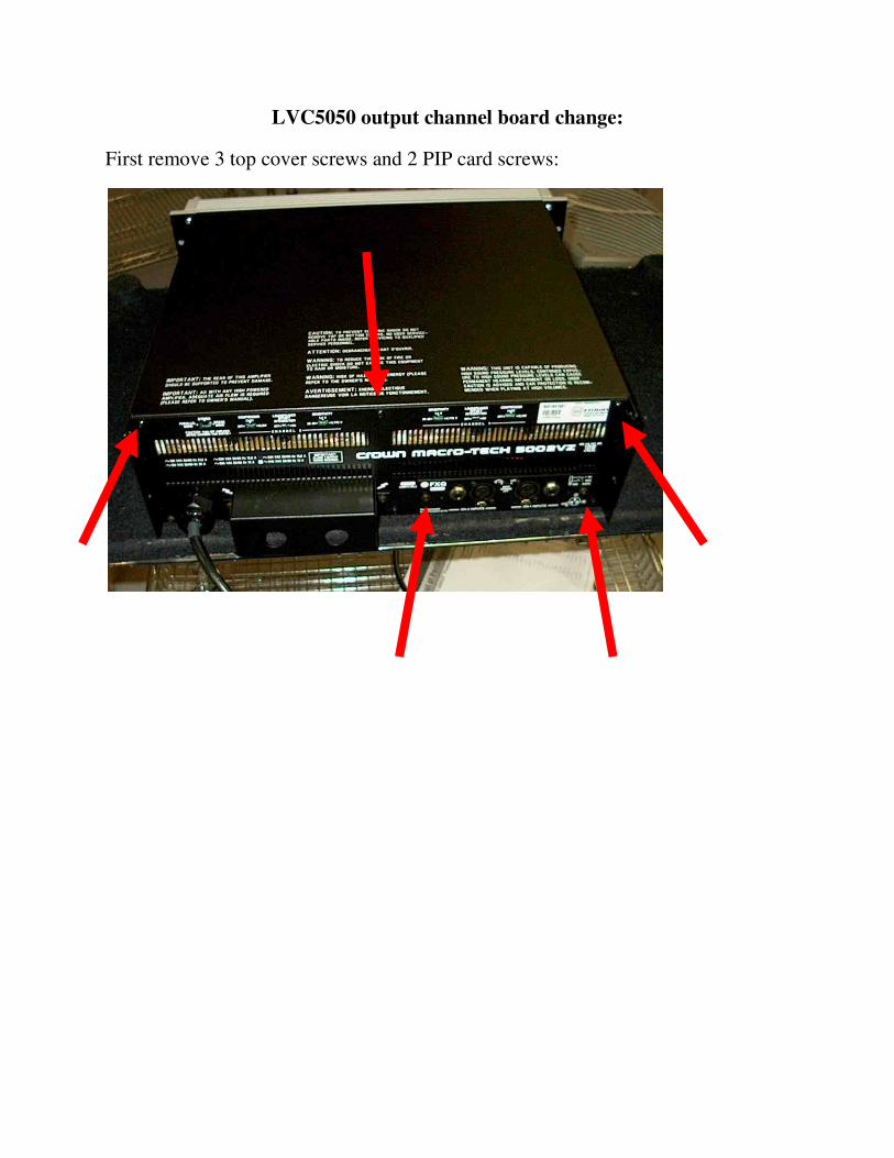
LVC5050 output channel board change:
First remove 3 top cover screws and 2 PIP card screws:

Then remove 11 side and back panel screws:

Then remove main board cables and then main board tray.
Then remove back panel. Your unit should now look similar to the picture below.

Next remove the 3screws holding in the output boards you need to replace.
Also loosen and carefully pull out the output flexible bus wires for the channel
being replaced.

Once these are disconnected you should be able to remove the output board stack
as seen here: Note-pay close attention to stack orientation (which board is up)

Remove the ribbon cables (P500 and P501 for Ch1) or (P600 and P601 for Ch2):

And then install them on the working replacement channel paying careful attention
to the orientation of the stack (which side is up)
Install the replacement output board stack into the amplifier.
Reinstall 3 mounting screws for channel.
Hook up all cables.

Put the P500/P501 ribbon cables on the working Ch2.

After exchanging the P600/P601 and the P500/P501 ribbon cables, flip the
working Ch2 output board stack and insert it into the place of the non-working
Ch1output board stack:


LVC5050 output channel board change:
First remove 3 top cover screws and 2 PIP card screws:

Then remove 11 side and back panel screws:

Then remove main board cables and then main board tray.
Then remove back panel. Your unit should now look similar to the picture below.

Next remove the 6 screws holding in the output boards.
Also loosen and carefully pull out the output flexible bus wires.

Once these are disconnected you should be able to remove the output board stack
as seen here:

Remove the P600 and P601 ribbon cables from the working Ch2:

Also remove the P500 andP501 ribbon cables from the non-working Ch1
Put the P500/P501 ribbon cables on the working Ch2.

After exchanging the P600/P601 and the P500/P501 ribbon cables, flip the
working Ch2 output board stack and insert it into the place of the non-working
Ch1output board stack:


Changing settings on a PIP card:
1. Remove screws holding in PIP card.
2. Remove PIP card.

3. Turn PIP card over. 4. Changing Jumper positions on PIP card.
a. J11,J12– Pots (external level control) Enabled/Disabled Ch1. Move from J12 to J11
b. J21,J22 – Pots (external level control) Enabled/Disabled Ch2. Move from J22 to J21
This should Disable the front level controls, without changing the DC Offset of either channel. If you wish to verify the DC offset do the following steps.
c. J10, J20 – Removing these will change the unit from DC coupled to AC coupled. d. JMPCC1, JMPCC2- Changing these jumpers will change the unit
from controlled voltage (CV) mode to controlled current (CC) mode, and allows user selectable compensation values in CC mode.
Setting DC offset: 5. With PIP card outside of unit resting on NON-conductive surface:

a. Short inputs b. Power unit on 6. Measure and adjust DC offset for both Ch1 and Ch2. a. Adjust Ch1 using VR10 b. Adjust Ch2 using VR6 7. Turn off power. 8. Re-install PIP card into back of amplifier, in the correct orientation.


