

Textbook for Vocational Training − Formulas and Tables Metal

Table of ContentsTextbook for Vocational Training − Formulas and Tables Metal..................................................................1
Preface...................................................................................................................................................11. Mathematics.......................................................................................................................................1
1.1. Mathematical symbols...............................................................................................................21.2. Greek alphabet..........................................................................................................................31.3. Rounding off numbers...............................................................................................................41.4. Basic arithmetical operations....................................................................................................51.5. Calculation of plane faces.........................................................................................................81.6. Calculation of bodies...............................................................................................................111.7. Preferred numbers..................................................................................................................13
2. Physics, mechanics..........................................................................................................................142.1. Physico−technical quantities...................................................................................................142.2. Quantities and their admissible units......................................................................................152.3. Transformation of forces.........................................................................................................222.4. Translation and rotation..........................................................................................................262.5. Friction coefficients.................................................................................................................272.6. Mass moments of inertia.........................................................................................................272.7. Stress and strain.....................................................................................................................272.8. Deformation in the case of bending stress..............................................................................302.9. Areal moments of inertia, moments of resistance...................................................................312.10. Moduli of elasticity.................................................................................................................332.11. Admissible strains (reference values)...................................................................................34
3. Technical drawing.............................................................................................................................343.1. Types of drawing.....................................................................................................................343.2. Sizes of drawings....................................................................................................................363.3. Subdivision of the sheet..........................................................................................................363.4. Lines........................................................................................................................................363.5. Lettering..................................................................................................................................383.6. Scales.....................................................................................................................................393.7. Rectangular project ion...........................................................................................................403.8. Figuring...................................................................................................................................423.9. Working and material characteristics......................................................................................483.10. Sectional view.......................................................................................................................493.11. Partial and interrupted representation...................................................................................523.12. Representation of thread.......................................................................................................533.13. Simplified representation of holes and counterbores............................................................543.14. Simplified representation of disconnectable connections.....................................................55
4. Metal materials.................................................................................................................................584.1. Characteristics........................................................................................................................584.2. Subdivision..............................................................................................................................584.3. Properties and use of important metals..................................................................................594.4. Ferrous materials....................................................................................................................654.5. Alloys of non−ferrous metals...................................................................................................754.6. Hard metals.............................................................................................................................79
5. Plastics.............................................................................................................................................806. Semi−finished products of steel........................................................................................................81
6.1. Bars, strips, sheets..................................................................................................................816.2. Standard sections...................................................................................................................856.3. Steel pipes for water and gas lines.........................................................................................91
7. Semi−finished products of aluminium and aluminium alloys............................................................927.1. Square bars.............................................................................................................................927.2. Hexagon bars..........................................................................................................................927.3. Round bars..............................................................................................................................93
8. Semi−finished products of copper and copper alloys.......................................................................948.1. Square bars.............................................................................................................................948.2. Hexagon bars..........................................................................................................................958.3. Round bars..............................................................................................................................96
9. Semi−finished products of hard metal..............................................................................................979.1. Blanks of sintered metal carbide.............................................................................................989.2. Cutting ceramics.....................................................................................................................98
i
Table of ContentsTextbook for Vocational Training − Formulas and Tables Metal
10. Semi−finished products of rigid polyvinyl chloride..........................................................................9810.1. Thin sheets of rigid PVC.......................................................................................................9810.2. Panels of rigid PVC, standard types.....................................................................................99
11. Semi−finished products of moulded laminate...............................................................................10011.1. Laminated paper sheets......................................................................................................10011.2. Laminated fabric sheets......................................................................................................100
12. Plates and sheets of different materials........................................................................................10013. Wire of different materials.............................................................................................................101
13.1. Steel wire............................................................................................................................10113.2. Copper or brass wire...........................................................................................................102
14. Types and functions......................................................................................................................10315. Connecting elements....................................................................................................................103
15.1. Bolts....................................................................................................................................10315.2. Screws................................................................................................................................10615.3. Nuts.....................................................................................................................................10715.4. Washers..............................................................................................................................10815.5. Securing devices for screws...............................................................................................10815.6. Pins.....................................................................................................................................10915.7. Keys....................................................................................................................................11015.8. Springs................................................................................................................................11215.9. Rivets..................................................................................................................................115
16. Load−carrying elements...............................................................................................................11616.1. Elastic springs.....................................................................................................................11616.2. Bearings..............................................................................................................................117
17. Transmission elements.................................................................................................................12317.1. Shafts..................................................................................................................................12317.2. Toothed gears.....................................................................................................................129
18. Subdivision of test procedures......................................................................................................13318.1. Non−dimensional testing.....................................................................................................13318.2. Dimensional testing.............................................................................................................135
19. Fitting systems..............................................................................................................................14519.1. Types of fits.........................................................................................................................14519.2. Systems of fits, basic hole, basic shaft...............................................................................14619.3. Examples of fits...................................................................................................................148
20. Scribing.........................................................................................................................................15220.1. Types of scribing.................................................................................................................15220.2. Notes on scribing................................................................................................................155
21. Fundamental forming by casting...................................................................................................15721.1. Shrinkage measures...........................................................................................................15721.2. Machining allowances for castings......................................................................................158
22. Forming.........................................................................................................................................15922.1. Mechanical bevelling...........................................................................................................15922.2. Bending...............................................................................................................................16022.3. Forging................................................................................................................................161
23. Separating....................................................................................................................................16223.1. Chiseling.............................................................................................................................16223.2. Shearing..............................................................................................................................16623.3. Sawing................................................................................................................................16823.4. Filing....................................................................................................................................17023.5. Flame cutting.......................................................................................................................17123.6. Drilling.................................................................................................................................17223.7. Countersinking....................................................................................................................17523.8. Reaming..............................................................................................................................17923.9. Thread cutting.....................................................................................................................18023.10. Turning..............................................................................................................................18323.11. Milling................................................................................................................................18823.12. Planing, slotting.................................................................................................................19223.13. Broaching..........................................................................................................................19623.14. Grinding.............................................................................................................................196
ii

Table of ContentsTextbook for Vocational Training − Formulas and Tables Metal
23.15. General data on cutting.....................................................................................................20024. Joining..........................................................................................................................................203
24.1. Screw joints.........................................................................................................................20324.2. Welded joints.......................................................................................................................21024.3. Riveted joints.......................................................................................................................21524.4. Soldered joints....................................................................................................................221
25. Changing of material properties....................................................................................................22425.1. Annealing of steel................................................................................................................22425.2. Hardening of steel...............................................................................................................22625.3. Tempering and hardening with subsequent drawing of steel..............................................230
iii

iv

Textbook for Vocational Training − Formulas and Tables Metal
CRYSTAL
Lehr− und Lernmittel,Informationen Beratung
Educational AidsLiterature, Consulting
Moyens didactiques,Informations, Service−conseil
Material didáctico,Informaciones, Asesoría
Feedback: IBE e.V.90−34−0101/2
Deutsche Gesellschaft fürTechnische Zusammenarbeit (GTZ) GmbH
Institut für berufliche Entwicklung e.V.Berlin
Original title:“Formeln und Tabellen − Metall”
Authors: Ingo Womer
Horst Thulke
Second edition © IBE
Institut für berufliche Entwicklung e.V.Parkstraße 2313187 Berlin
Order No.: 90−34−0101/2
Preface
This book of tables concentrates on the fields of the metal−working industry and the metal trade. The book isintended as a proper reference book, both for trainees and as an aid to practical work by craftsmen. Importantmathematical, physical and technical fundamentals and essential specific technical concepts, work tables,work rules, etc., are given in the clear and concise manner characteristic of a book of tables.
This book has been elaborated on the basis of advanced knowledge and findings contained in the vocationaltraining.
The subject−matter has been suitably compiled in main sections.
1. Mathematics
1

1.1. Mathematical symbols
Symbol Explanation
... to
e.g.: k = 1, 2, ..., n
= equal to
identically equal to
e.g.: f(x) 0. The function f has the valueof zero at any point.
? not equal to, unequal
not identically equal to
~ proportional, similar
? approximate, almost equal, about
(The last figure is determined by means ofthe rounding rule. For rounding off, seeSection 1.3.)
corresponds to
< smaller than
> greater than
? smaller than or equal to, equal at most
? greater than or equal to, equal at least
small as against of another order
great as against of magnitude
+ plus
− minus
.,x times
−,/,: by, divided, by, to
% percent, of a hundred (10−2)
‰ per mille, of a thousand (10−3)
|| parallel
not parallel
‘‘ parallel in the same direction
‘? parallel in the opposite direction
at right angles to, perpendicular on
triangle
E congruent
angle
2

line AB
arc AB
z amount of z
arc z arc z
n! factorial n
n above p binominal coefficient
? sum
? product
square root; nth root of
? Pi of this circle, ? = 3.14159...
f(x) f of x
value of the function f at point x
? infinite
loga logarithm to base a
lg logarithm to base ten lg x = log10x
lb logarithm to base two lb x = log2x
ln natural logarithm ln x = logex
sin sine trigonometric
cos cosine functions
tan tangent or
cot cotangent functions of angles
arc sin inverse sine arc functions,
arc cos arc cosine inverse functions of
arc tan arc inverse tangent the trigonometric
arc cot arc inverse cotangent functions
1.2. Greek alphabet
Letter capital small Designation Representation in roman type
A ? Alpha A, a
B ? Beta B, b
? ? Gamma G, g
? ? Delta D, d
E ? Epsilon E, e
Z ? Zeta Z, z
H ? Eta E, e
3

? ? Theta Th, th
I ? Jota I, i
K ? Kappa K, k
? ? Lambda L, l
M ? My M, m
N ? Ny N, n
? ? Xi X, x
O ? Omikron O, o
? ? Pi P, p
P ? Rho R(h), r(h)
? ? Sigma S, s
T ? Tau T, t
Y ? Ypsilon Y, y
? ? Phi Ph, ph
X ? Chi Ch, ch
? ? Psi Ps, ps
? ? Omega O, o
In technology, letters of the Greek Alphabet are frequently used as symbols of physical quantities; e.g. ?, ?, ?for angle quantities; ? for efficiency; ? as the unit symbol for electrical resistance. (See Section 2.1.).
1.3. Rounding off numbers
When rounding off numbers, one or more figures at the end of a number are substituted by zeros. The figureimmediately to the left is either retained (rounding down) or increased by 1 (rounding up).
Roundingoff
Rule Example
Roundingdown
The last figure to be given is retained when followed by a 0, 1, 2, 3 or 4 3.01234
? 3.0123
? 3.012
? 3.01
? 3.0 ? 3
Rounding up The number to be indicated is increased by 1 when followed by a 6, 7, 8 or 9. 4.6789
? 4.679
? 4.68
? 4.7 ? 5
Rounding off5
If the last figure to be given is followed by at least one number which differsfrom 0 after a 5, the last figure is increased by 1.If the last figure to be given is followed by a 5 which is known to have beenobtained by rounding off,
5.153 ?5.2
4
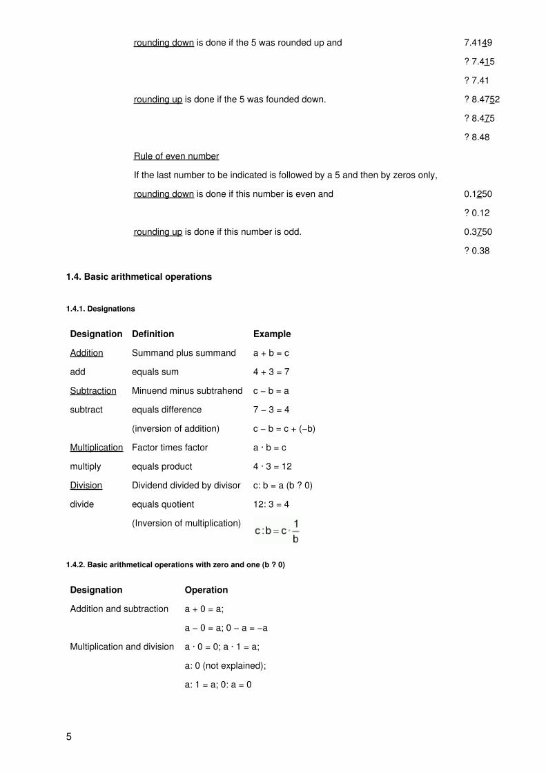
rounding down is done if the 5 was rounded up and 7.4149
? 7.415
? 7.41
rounding up is done if the 5 was founded down. ? 8.4752
? 8.475
? 8.48
Rule of even number
If the last number to be indicated is followed by a 5 and then by zeros only,
rounding down is done if this number is even and 0.1250
? 0.12
rounding up is done if this number is odd. 0.3750
? 0.38
1.4. Basic arithmetical operations
1.4.1. Designations
Designation Definition Example
Addition Summand plus summand a + b = c
add equals sum 4 + 3 = 7
Subtraction Minuend minus subtrahend c − b = a
subtract equals difference 7 − 3 = 4
(inversion of addition) c − b = c + (−b)
Multiplication Factor times factor a · b = c
multiply equals product 4 · 3 = 12
Division Dividend divided by divisor c: b = a (b ? 0)
divide equals quotient 12: 3 = 4
(Inversion of multiplication)
1.4.2. Basic arithmetical operations with zero and one (b ? 0)
Designation Operation
Addition and subtraction a + 0 = a;
a − 0 = a; 0 − a = −a
Multiplication and division a · 0 = 0; a · 1 = a;
a: 0 (not explained);
a: 1 = a; 0: a = 0
5
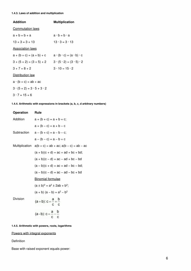
1.4.3. Laws of addition and multiplication
Addition Multiplication
Commutation laws
a + b = b + a a · b = b · a
13 + 3 = 3 + 13 13 · 3 = 3 · 13
Association laws
a + (b + c) = (a + b) + c a · (b · c) = (a · b) · c
3 + (5 + 2) = (3 + 5) + 2 3 · (5 · 2) = (3 · 5) · 2
3 + 7 = 8 + 2 3 · 10 = 15 · 2
Distribution law
a · (b + c) = ab + ac
3 · (5 + 2) = 3 · 5 + 3 · 2
3 · 7 = 15 + 6
1.4.4. Arithmetic with expressions in brackets (a, b, c, d arbitrary numbers)
Operation Rule
Addition a + (b + c) = a + b + c;
a + (b − c) = a + b − c
Subtraction a − (b + c) = a − b − c;
a − (b − c) = a − b + c
Multiplication a(b + c) = ab + ac; a(b − c) = ab − ac
(a + b)(c + d) = ac + ad + bc + bd;
(a + b)(c − d) = ac − ad + bc − bd
(a − b)(c + d) = ac + ad − bc − bd;
(a − b)(c − d) = ac − ad − bc + bd
Binomial formulae
(a ± b)2 = a2 ± 2ab + b2;
(a + b) (a − b) = a2 − b2
Division
1.4.5. Arithmetic with powers, roots, logarithms
Powers with integral exponents
Definition
Base with raised exponent equals power:
6

an = c (a ? 0)
In the case of natural exponents, raising to a power can be explained as the repeated multiplication of thesame factors:
Laws
(m, n integral; a · b ? 0; a, b arbitrarily real)
a
1
= a; a
0
= 1; (a ? 0); (a ? 0)
am · an = am+n; am · bm = (ab)m
; (a
m
)
n
= a
m · n
Roots
(Extraction of a root, 1st inversion of raising to a power)
Definition
The nth root from radicand b is equal to that non−negative value a which results in b when raised to the powern:
(b ? 0; n natural)
(n index of root; b radicand; a value of root)
Laws
(m, n natural; a ? 0; b > 0)
(n natural); (n natural)
(not explained)
;
;
Logarithms
(Taking the logarithm of a number; 2nd inversion of raising to a power)
Definition
7

The logarithm of b to base a is the number c which must be used for raising to a power in order to obtain b:
c = loga b (a, b positive; a ? 1); a logab = b
(b inverse logarithm; a base; c logarithm)
Laws
(equal bases; b, b1, b2 > 0; a > 0; a ? 1; n arbitrarily real)
loga 1 ? 0 (a ? 1; positive)
log1 a not explained
loga (b1 · b2 = loga b1 + loga b2;
;
loga bn = n · loga b
;
1.5. Calculation of plane faces
Surface area A, circumference of face u
General triangle
Equilateral triangle
u = a + b + c
Right−angled triangle
Altitude theorem: h2 = p · q;Euclidean theorem: a2 = p · c;b2 = q · cPythagoras theorem; a2 + b2
= c2
8
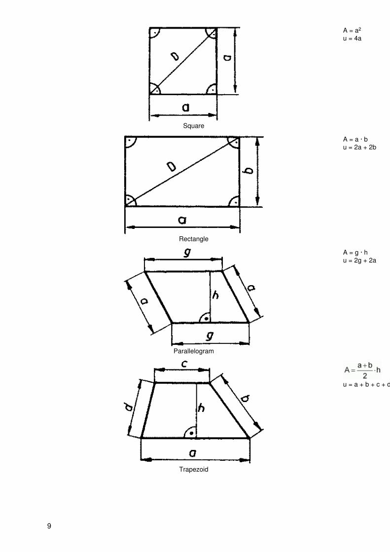
Square
A = a2
u = 4a
Rectangle
A = a · bu = 2a + 2b
Parallelogram
A = g · hu = 2g + 2a
Trapezoid
u = a + b + c + d
9
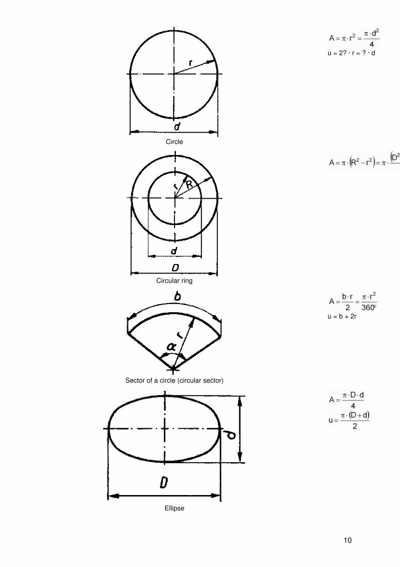
Circle
u = 2? · r = ? · d
Circular ring
Sector of a circle (circular sector)
u = b + 2r
Ellipse
10

1.6. Calculation of bodies
Volume of body V; surface of body A0
Cube
V = a3
A0 = 6a2
Cuboid
V = a · b · cA0 = 2 · (ab + ac + bc)
Pyramid
11

Cylinder
Hollow cylinder
V = ? · h · (R2 − r2)
Cone
A0 = ? · r · (r + s)
12

Sphere
A0 = 4? · r2 = ? · d2
1.7. Preferred numbers
Basic series Basic series
R 5 R 10 R 20 R 40 R 5 R 10 R 20 R40
1.00 1.00 1.00 1.00 4.00 4.00 4.00 4.00
1.06 4.25
1.12 1.12 4.50 4.50
1.18 4.75
1.25 1.25 1.25 5.00 5.00 5.00
1.32 5.30
1.40 1.40 5.60 5.60
1.50 6.00
1.60 1.60 1.60 1.60 6.30 6.30 6.30 6.30
1.70 6.70
1.80 1.80 7.10 7.10
1.90 7.50
2.00 2.00 2.00 8.00 8.00 8.00
2.12 8.50
2.24 2.24 9.00 9.00
2.36 9.50
2.50 2.50 2.50 2.50
2.65
2.80 2.80
3.00
3.15 3.15 3.15
3.35
3.55 3.55
3.75
13

2. Physics, mechanics
2.1. Physico−technical quantities
Physico−technical quantities (known as quantities) are measurable characteristics of objects, processes orconditions. With regard to quality, they are clearly defined and can be quantitatively determined (measured).
Example:
Numerical value × unit =quantity
3.500 · mm = 1
2.1.1. Units of physico−technical quantities
Type of unit Explanation Example
Basic units of SI Basic units are defined units which are chosen independently ofone another and form the basis of the international system of units(Système International d’Unités, abbreviated “SI” in all languages)
Metre for lengthKilogramme forweightSecond for time;Ampère forcurrent intensity;Kelvin fortemperature;Mol for amount ofsubstance;Candela forluminous intensity
Derived SI units Derived SI units are all units formed as a power product with thenumerical factor 1 from the basic of the SI
1 N = 1m · kg · s−2
1 Pa = 1N · m−2
Supplementary SIunits
The supplementary SI units should be used like basic units of theSI if physical circumstances require it
Radian for planeangle;Steradian for solidangle;
Units extraneousto SI
Units extraneous to SI do not belong to the SI and are units whoserelation to the SI units contains a numerical factor which differsfrom one.
Units extraneousto the SI
These are admissible units which are extraneous to the SI:
− SI units with SI prefixes 1 mm = 10−3 m
− Generally accepted units; 1 min = 60 s
− Units valid in special fields 1 ha = 104 m2
hectare for landand real estate
− Valid units for relative quantities 1 % = 1 · 10−2
2.1.2. SI prefixes
SI prefixes are used for forming decimal multiples and parts of SI units and units extraneous to the SI (if notexpressly omitted).
(See Section 1.4.5.)
14
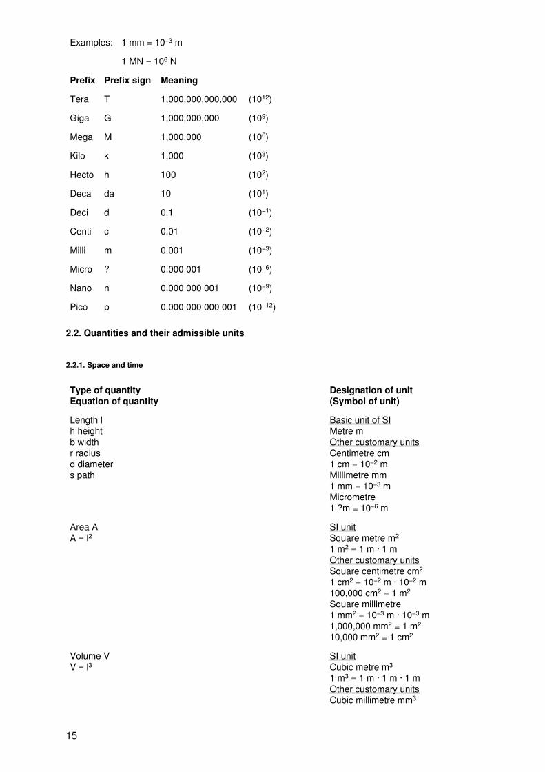
Examples: 1 mm = 10−3 m
1 MN = 106 N
Prefix Prefix sign Meaning
Tera T 1,000,000,000,000 (1012)
Giga G 1,000,000,000 (109)
Mega M 1,000,000 (106)
Kilo k 1,000 (103)
Hecto h 100 (102)
Deca da 10 (101)
Deci d 0.1 (10−1)
Centi c 0.01 (10−2)
Milli m 0.001 (10−3)
Micro ? 0.000 001 (10−6)
Nano n 0.000 000 001 (10−9)
Pico p 0.000 000 000 001 (10−12)
2.2. Quantities and their admissible units
2.2.1. Space and time
Type of quantityEquation of quantity
Designation of unit(Symbol of unit)
Length lh heightb widthr radiusd diameters path
Basic unit of SIMetre mOther customary unitsCentimetre cm1 cm = 10−2 mMillimetre mm1 mm = 10−3 mMicrometre1 ?m = 10−6 m
Area AA = l2
SI unitSquare metre m2
1 m2 = 1 m · 1 mOther customary unitsSquare centimetre cm2
1 cm2 = 10−2 m · 10−2 m100,000 cm2 = 1 m2
Square millimetre1 mm2 = 10−3 m · 10−3 m1,000,000 mm2 = 1 m2
10,000 mm2 = 1 cm2
Volume VV = l3
SI unitCubic metre m3
1 m3 = 1 m · 1 m · 1 mOther customary unitsCubic millimetre mm3
15

1 mm3 = 10−3 m · 10−3 m · 10−3 m1,000,000,000 mm3 = 1 m3
Millilitre ml1 ml = 10−9 m3
1 ml = 1 mm3
Litre l1 l = 10−3 m3
1 l = 1,000 mlHectolitre hl1 hl = 10−1 m3
1 hl = 100 l
Plane angle SI unitRadian rad
Other customary units without SI prefixesDegree °
1° = 60’ = 3600”Minute ‘60’ = 1°Second “60” = 1’
Solid angle ? SI unitSteradian sr
Time t Base unit of the SISecond sOther customary units without SI prefixesMinute min1 min = 60 sHour h1 h = 60 min = 3600 sDay d1 d = 24 h = 86,400 s
Frequency f SI unitHertz Hz1 Hz = 1/s = 1 s−1
Other customary unitsKilohertz kHz1 kHz = 103 HzMegahertz MHz1 MHz = 106 Hz
Speed n
(Frequency of revolutions)
Other customary units without SI prefixesRevolutions per second1/s = 1 s−1
Revolutions per minute1/min = 1 min−1
Velocity v
Cutting speedv = ? · d · n
SI unitMetre per second m/sOther customary unitsKilometre per hour km/h1 km/h = 0.2778 m/sMetre per minute m/min1 m/min = 1.667 · 10−2 m/s
16
Acceleration a SI unitMetre per square second m/s2
Angular velocity
? = 2? · n
SI unitRadian per second rad/sOther customary unitsDegree per second °/s
Angular acceleration SI unitRadian per square second rad/s2
Other customary unitsDegree per square second °/s2
Volumetric rate of flow (volume flow, volume throughput)SI unitCubic metre per second m3/sOther customary unitsCubic metre per hour m3/hLitre per minute l/min
Weight m Basic unit of the SIKilogramme kgOther customary unitsGramme g 1 g = 10−3 kgMilligramme mg1 mg = 10−3 g = 10−6 kg
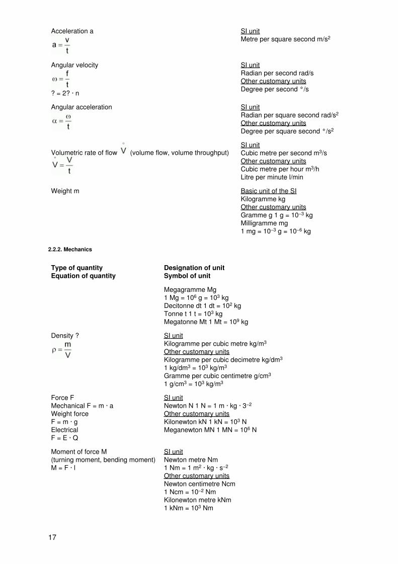
2.2.2. Mechanics
Type of quantityEquation of quantity
Designation of unitSymbol of unit
Megagramme Mg1 Mg = 106 g = 103 kgDecitonne dt 1 dt = 102 kgTonne t 1 t = 103 kgMegatonne Mt 1 Mt = 109 kg
Density ? SI unitKilogramme per cubic metre kg/m3
Other customary unitsKilogramme per cubic decimetre kg/dm3
1 kg/dm3 = 103 kg/m3
Gramme per cubic centimetre g/cm3
1 g/cm3 = 103 kg/m3
Force FMechanical F = m · aWeight forceF = m · gElectricalF = E · Q
SI unitNewton N 1 N = 1 m · kg · 3−2
Other customary unitsKilonewton kN 1 kN = 103 NMeganewton MN 1 MN = 106 N
Moment of force M(turning moment, bending moment)M = F · l
SI unitNewton metre Nm1 Nm = 1 m2 · kg · s−2
Other customary unitsNewton centimetre Ncm1 Ncm = 10−2 NmKilonewton metre kNm1 kNm = 103 Nm
17
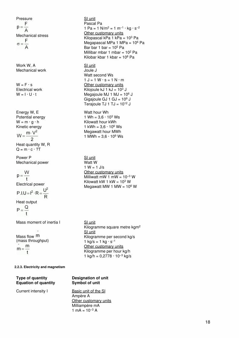
Pressure
Mechanical stress
SI unitPascal Pa1 Pa = 1 N/m2 = 1 m−1 · kg · s−2
Other customary unitsKilopascal kPa 1 kPa = 103 PaMegapascal MPa 1 MPa = 106 PaBar bar 1 bar = 105 PaMillibar mbar 1 mbar = 102 PaKilobar kbar 1 kbar = 108 Pa
Work W, AMechanical work
W = F · sElectrical workW = I · U · t
SI unitJoule JWatt second Ws1 J = 1 W · s = 1 N · mOther customary unitsKilojoule kJ 1 kJ = 103 JMegajoule MJ 1 MJ = 106 JGigajoule GJ 1 GJ = 109 JTerajoule TJ 1 TJ = 1012 J
Energy W, EPotential energyW = m · g · hKinetic energy
Heat quantity W, RQ = m · c · ?T
Watt hour Wh1 Wh = 3,6 · 103 WsKilowatt hour kWh1 kWh = 3,6 · 106 WsMegawatt hour MWh1 MWh = 3,6 · 109 Ws
Power PMechanical power
Electrical power
Heat output
SI unitWatt W1 W = 1 J/sOther customary unitsMilliwatt mW 1 mW = 10−3 WKilowatt kW 1 kW = 103 WMegawatt MW 1 MW = 106 W
Mass moment of inertia I
Mass flow (mass throughput)
SI unitKilogramme square metre kgm2
SI unitKilogramme per second kg/s1 kg/s = 1 kg · s−1
Other customary unitsKilogramme per hour kg/h1 kg/h = 0,2778 · 10−3 kg/s
2.2.3. Electricity and magnetism
Type of quantityEquation of quantity
Designation of unitSymbol of unit
Current intensity I Basic unit of the SIAmpère AOther customary unitsMilliampère mA1 mA = 10−3 A
18

Kiloampère kA1 kA = 103 A
Quantity of electricity Q(electric charge)Q = I · t
SI unitCoulomb C1 C = 1 s · AOther customary unitsMillicoulomb mC 1 mC = 10−3 CKilocoulomb kC 1 kC = 103 CAmpère hour Ah1 Ah = 3600 C = 3,6 kC
Electric power P
Active powerP = I · U · cos ?Reactive powerQ = I · U · sin ?Apparent powerS = I · U
SI unitWatt W1 W = 1 J/sOther customary unitsMilliwatt mW 1 mW = 10−3 WKilowatt kw 1 kw = 103 WMegawatt MW 1 MW = 106 W
Voltage U SI unitVolt V 1 V = 1 W/AOther customary unitsMillivolt mV 1 mV = 10−3 VKilovolt kV 1 kV = 103 VMegavolt MV 1 MV = 106 V
Electric field strengthE
SI unitVolt per metre V/m1 V/m · 1m · kg · s−3 · A−1
Other customary unitsKilovolt per metre kV/m1 kV/m = 103 V/mVolt per centimetre V/cm1 V/cm = 102 V/m
Electric capacity C SI unitFarad F 1 F = 1 C/VOther customary unitsPicofarad pF 1 pF = 10−12 FNanofarad nF 1 nF = 10−9 FMicrofarad ?F 1 ?F = 10−6 F
Electric resistance R SI unitOhm ? 1 ? = 1 V/AOther customary unitsMilliohm m? 1 m? = 10−3 ?Kiloohm k? 1 k? = 103 ?Megaohm M? 1 M? = 106 ?
Specific electric resistance SI unitOhmmeter ?m
Type of electric conductor G SI unitSiemens S 1 S = 1/?Other customary unitsMillisiemens mS 1 mS = 10−3 SKilosiemens kS 1 kS = 103 S
19

Electric conductivity SI unitSiemens per metre S/m1 S/m = 1/(? · m)
Magnetic flux ?? = B · A
SI unitWeber Wb1 Wb = 1 V · s
Magnetic induction B SI unitTesla T 1 T = 1 Wb/m2
Magnetic field strength H SI unitAmpère per metre A/m1 A/m = 1 m−1 · AOther customary unitsAmpère per millimetre A/mm1 A/mm = 103 A/mAmpère per centimetre1 A/cm = 102 A/m
Inductance H SI unitHenry H 1 H = 1 Wb/AOther customary unitsPicohenry pH 1 pH = 10−12 HNanohenry nH 1 nH = 10−9 HMillihenry mH 1 mH = 10−3 H
Magnetic permeability ?
Field constant ?0?0 = 12.566 · 10−7 H/m
SI unitHenry per metre H/m1 H/m = 1 m
2.2.4. Heat
Type of quantityEquation of quantity
Designation of unitSymbol of unit
Temperature T(thermodynamic)Celsius temperature ÑÑ = T − 273,15
Basic unit of the SIKelvin KIndication of temperature differential in KelvinOther customary unitDegree Celsius °C
Heat quantity Q SI unitJoule J 1 J = 1 W · s
Calorific capacity C SI unitJoule per Kelvin J/K
2.2.5. Physical chemistry
Type of quantityEquation of quantity
Designation of unitSymbol of unit
Amount of substance n Basic unit of the SIMol molOther customary units
20

Micromol ?mol1 ?mol = 10−6 molMillimol mmol1 mmol = 10−3 molKilomol kmol1 kmol = 103 mol
Molar mass MM SI unitKilogram per mol kg/mol1 kg/mol = 1 kg · mol−1
Other customary unitsGramme per mol g/mol1 g/mol = 10−3 kg/molGramme per kilomol g/mol1 g/kmol = 10−6 kg/mol
Molar volume Vm SI unitCubic metre per mol m3/molOther customary unitsCubic metre per kilomol m3/kmol1 m3/kmol = 10−3 m3/molLitre per mol l/mol1 l/mol = 10−3 m3/mol
Molal concentration(molarity)
SI unitMol per cubic metre mol/m3
Other customary unitsKilomol per cubic metre kmol/m3
1 kmol/m3 = 103 mol/m3
Mol per litre mol/l1 mol/l = 103 mol/m3
2.2.6. Optical radiation
Type of quantityEquation of quantity
Designation of unitSymbol of unit
Luminous intensity IV Basic unit of the SICandela cdOther customary unitsMillicandela mcd1 mcd = 10−3 cdKilocandela kcd1 kcd = 103 cd
Luminance LV SI unitCandela per square metre cd/m2
Other customary unitsCandela per square centimetre cd/cm2
1 cd/cm2 = 104 cd/m2
Luminous flux SI unitLumen lm 1 lm = 1 cd · srOther customary unitsMillilumen mlm1 mlm = 10−3 lmKilolumen klm1 klm = 103 lm
Illumination EV SI unitLux lx 1 lx = 1 lm/m2
Other customary unitsMillilux mlx 1 mlx = 10−3 lx
21

Kilolux klx 1 klx = 103 lx
Light quantity QQ = ?v l t
SI unitLumen second lms1 lms = 1 s · cd · sr
2.3. Transformation of forces
Designation Equilibrium
Parallelogram of forces
F has the same effect as F1 and F2 jointly
Lever (theorem of moments)
F1 · l1 = F2 · l2
FH = FG. sin ?FN = FG. cos ?FH · l = FG · hFN · l = FG · gFH = force at the slopeFN = normal forceFG = weight
22
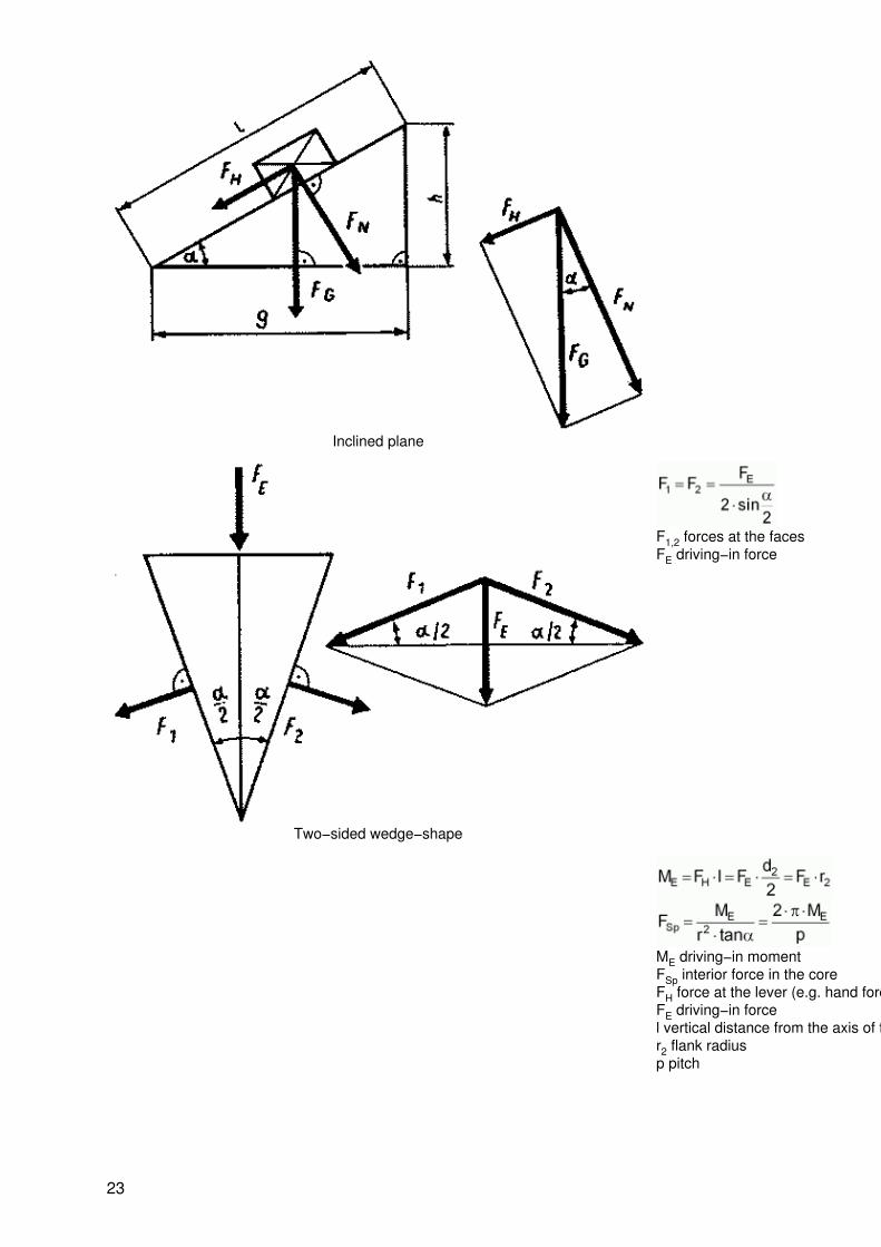
Inclined plane
Two−sided wedge−shape
F1,2 forces at the facesFE driving−in force
ME driving−in momentFSp interior force in the coreFH force at the lever (e.g. hand force)FE driving−in forcel vertical distance from the axis of the threadr2 flank radiusp pitch
23

Thread with vertical flanks
Fixed pulley
F1 = F2s1 = s2F1 · S1 = F2 · S2
Loose pulley
s1 = 2 · s2
24

Shaft with pulleys
Pulley block
s1 = n · s2n Number of carrying cables
Belt drive
Fu1 = Fu2; Vu1 = Vu2
; Fu Peripheral forceVu Peripheral velocity
25
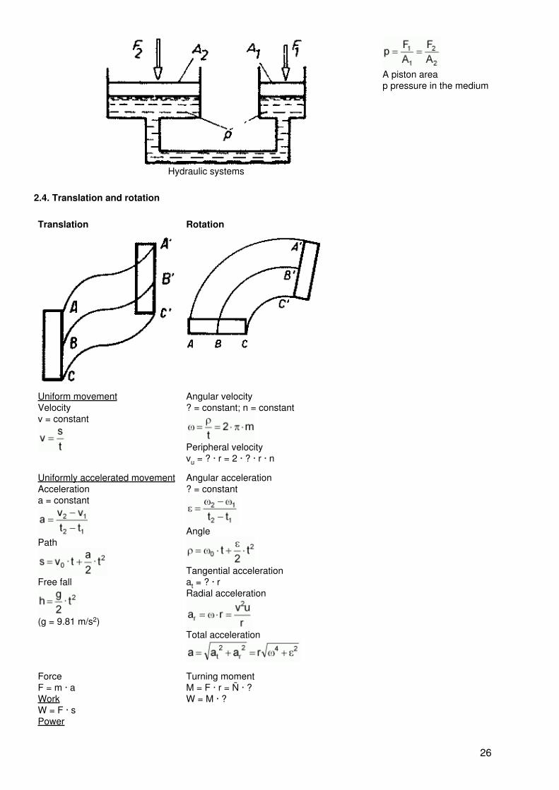
Hydraulic systems
A piston areap pressure in the medium
2.4. Translation and rotation
Translation Rotation
Uniform movementVelocityv = constant
Angular velocity? = constant; n = constant
Peripheral velocityvu = ? · r = 2 · ? · r · n
Uniformly accelerated movementAccelerationa = constant
Path
Free fall
(g = 9.81 m/s2)
Angular acceleration? = constant
Angle
Tangential accelerationat = ? · rRadial acceleration
Total acceleration
ForceF = m · aWorkW = F · sPower
Turning momentM = F · r = Ñ · ?W = M · ?
26
Kinetic energy
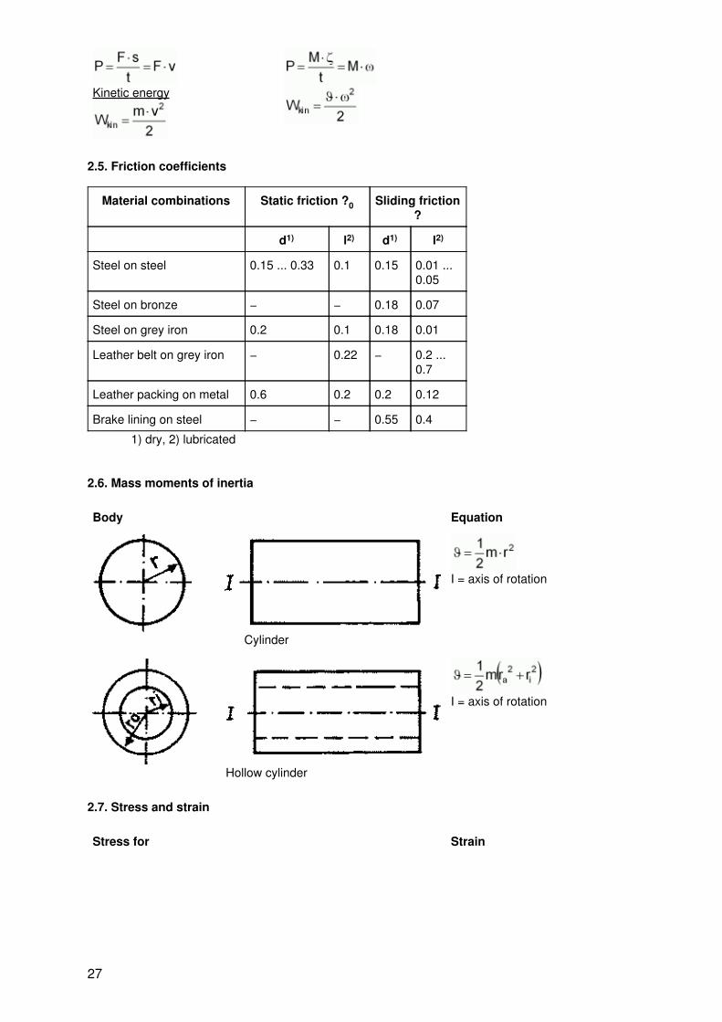
2.5. Friction coefficients
Material combinations Static friction ?0 Sliding friction?
d1) l2) d1) l2)
Steel on steel 0.15 ... 0.33 0.1 0.15 0.01 ...0.05
Steel on bronze − − 0.18 0.07
Steel on grey iron 0.2 0.1 0.18 0.01
Leather belt on grey iron − 0.22 − 0.2 ...0.7
Leather packing on metal 0.6 0.2 0.2 0.12
Brake lining on steel − − 0.55 0.4
1) dry, 2) lubricated
2.6. Mass moments of inertia
Body Equation
Cylinder
I = axis of rotation
Hollow cylinder
I = axis of rotation
2.7. Stress and strain
Stress for Strain
27
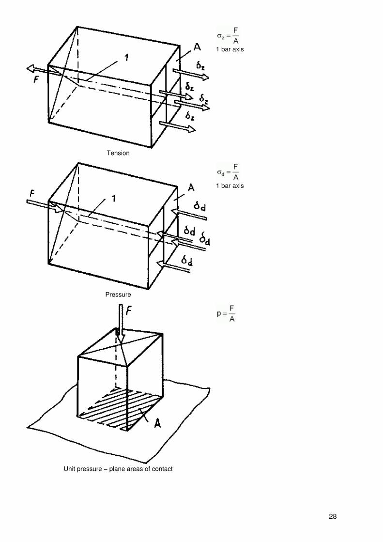
Tension
1 bar axis
Pressure
1 bar axis
Unit pressure − plane areas of contact
28
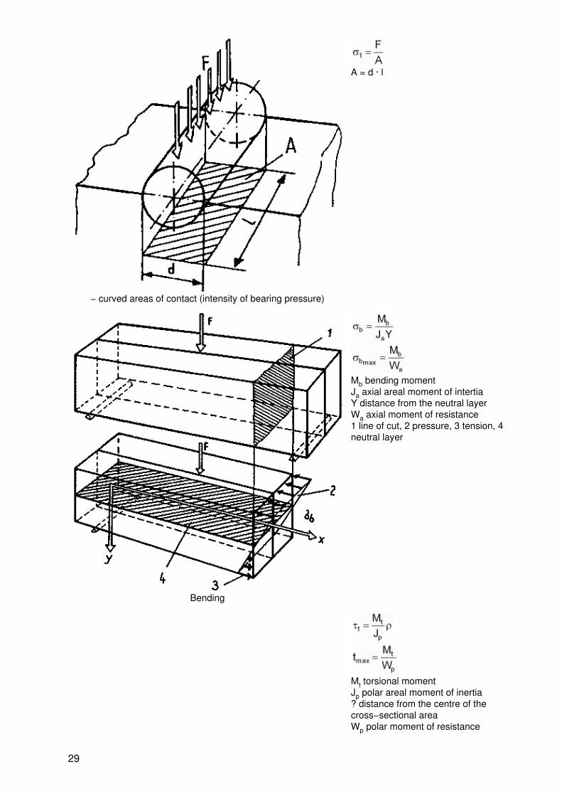
− curved areas of contact (intensity of bearing pressure)
A = d · l
Bending
Mb bending momentJa axial areal moment of intertiaY distance from the neutral layerWa axial moment of resistance1 line of cut, 2 pressure, 3 tension, 4neutral layer
Mt torsional momentJp polar areal moment of inertia? distance from the centre of thecross−sectional areaWp polar moment of resistance
29
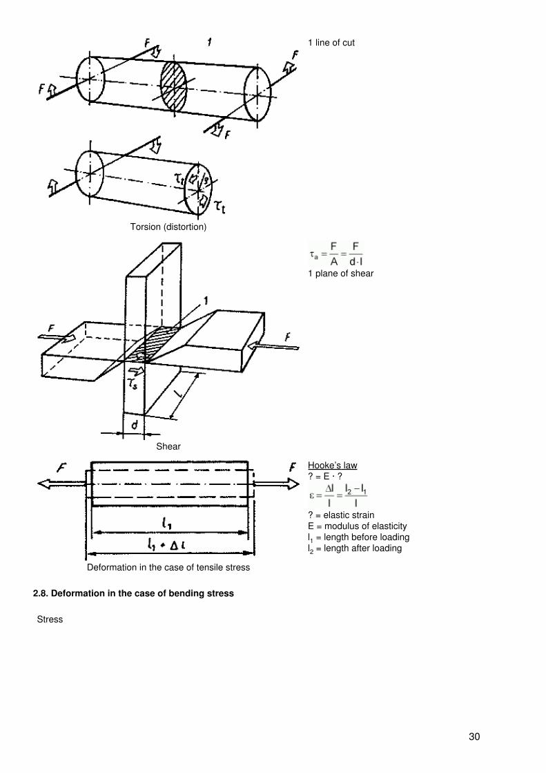
Torsion (distortion)
1 line of cut
Shear
1 plane of shear
Deformation in the case of tensile stress
Hooke’s law? = E · ?
? = elastic strainE = modulus of elasticityl1 = length before loadingl2 = length after loading
2.8. Deformation in the case of bending stress
Stress
30

Bearing reactions
Bending moment (max.)
Deflection
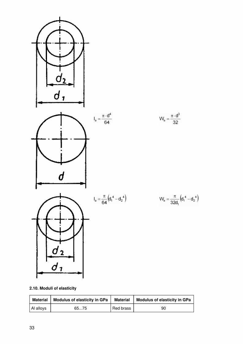
2.9. Areal moments of inertia, moments of resistance
Figure Axial areal moment of resistance Moment of resistance
31

Figure Polar areal moment of resistance Moment of resistance
32
2.10. Moduli of elasticity
Material Modulus of elasticity in GPa Material Modulus of elasticity in GPa
Al alloys 65...75 Red brass 90
33

Lead 15...18 Silver 70...80
Copper 125 Steel 200...220
Grey iron 75...105 Cast steel 210
Brass 80...100 Tungsten 350...400
Nickel 200...220 Zinc 110...130
2.11. Admissible strains (reference values)
Material Load condition Admissible load in MPa when stressed for
Pressure Tension Thrust Shear deformation
General structural steel I 70 70 60 70
II 50 50 40 50
III − 40 30 40
Cast iron I 90 30 30 −
II 55 13 18 −
III − 18 15 −
Nickel steel I − 75 75 80
II 65 60 60 60
III − 45 45 45
Wrought steel I 90 90 75 90
II 60 60 50 60
III − 30 25 30
Cast steel I 120 90 72 95
II 75 50 45 55
III − 40 35 47
Special steels I 180 180 120 180
II 150 150 100 150
Spring steel III 100 100 65 100
Tool steel
I dead; II increasing; III varying
3. Technical drawing
3.1. Types of drawing
Type Content Example
34
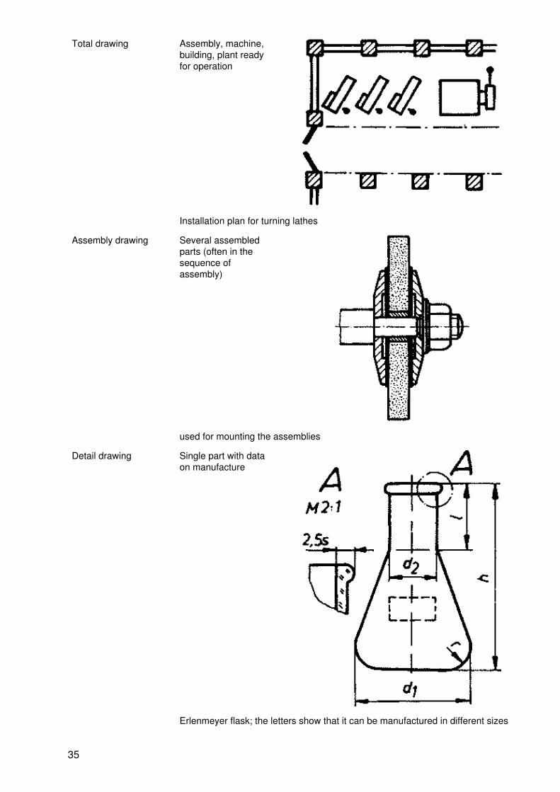
Total drawing Assembly, machine,building, plant readyfor operation
Installation plan for turning lathes
Assembly drawing Several assembledparts (often in thesequence ofassembly)
used for mounting the assemblies
Detail drawing Single part with dataon manufacture
Erlenmeyer flask; the letters show that it can be manufactured in different sizes
35
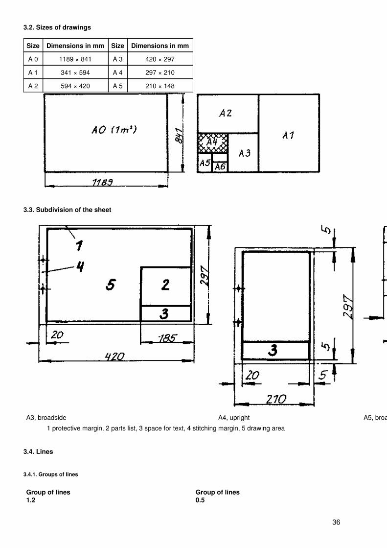
3.2. Sizes of drawings
Size Dimensions in mm Size Dimensions in mm
A 0 1189 × 841 A 3 420 × 297
A 1 341 × 594 A 4 297 × 210
A 2 594 × 420 A 5 210 × 148
3.3. Subdivision of the sheet
A3, broadside A4, upright A5, broadside
1 protective margin, 2 parts list, 3 space for text, 4 stitching margin, 5 drawing area
3.4. Lines
3.4.1. Groups of lines
Group of lines1.2
Group of lines0.5
36
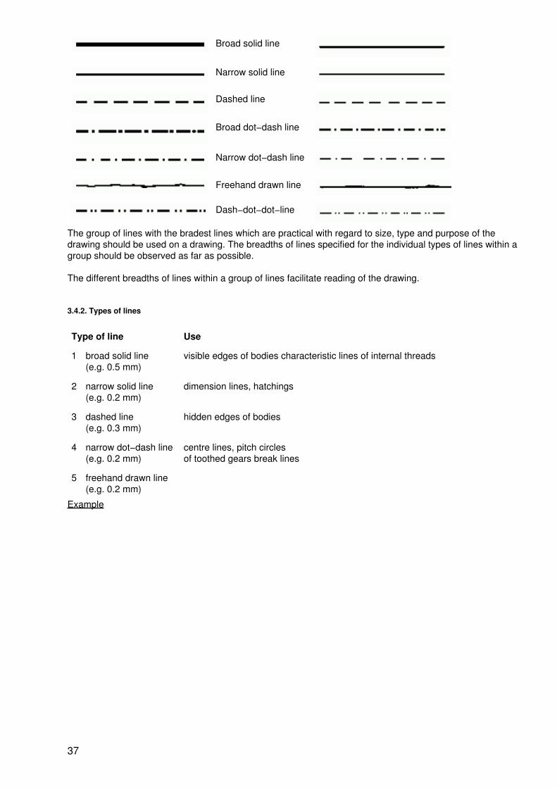
Broad solid line
Narrow solid line
Dashed line
Broad dot−dash line
Narrow dot−dash line
Freehand drawn line
Dash−dot−dot−line
The group of lines with the bradest lines which are practical with regard to size, type and purpose of thedrawing should be used on a drawing. The breadths of lines specified for the individual types of lines within agroup should be observed as far as possible.
The different breadths of lines within a group of lines facilitate reading of the drawing.
3.4.2. Types of lines
Type of line Use
1 broad solid line(e.g. 0.5 mm)
visible edges of bodies characteristic lines of internal threads
2 narrow solid line(e.g. 0.2 mm)
dimension lines, hatchings
3 dashed line(e.g. 0.3 mm)
hidden edges of bodies
4 narrow dot−dash line(e.g. 0.2 mm)
centre lines, pitch circlesof toothed gears break lines
5 freehand drawn line(e.g. 0.2 mm)
Example
37

3.5. Lettering
For lettering technical drawings, standardized vertical medium−spaced lettering is being used increasingly.
3.5.1. Main dimensions of vertical medium−spaced lettering
Height of letters h 2.5 3.5 5.0 7.0 10.0 14.0 20.0
Breadth of letters s 0.25 0.35 0.5 0.7 1.0 1.4 2.0
3.5.2. Vertical medium−spaced lettering
38

3.6. Scales
Scaling up 50:1 10n:1 −
5:1 10:1 20:1
− − 2:1
Natural size 1:1
Scaling down 1:2 − −
1:20 1:10 1:5
1:200 1:100 1:50
1:(2×10n) 1:10n 1:(5×10n)
39
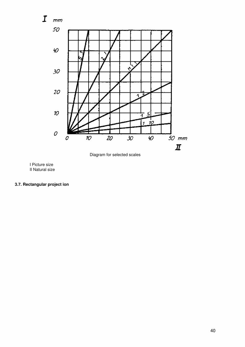
Diagram for selected scales
I Picture sizeII Natural size
3.7. Rectangular project ion
40
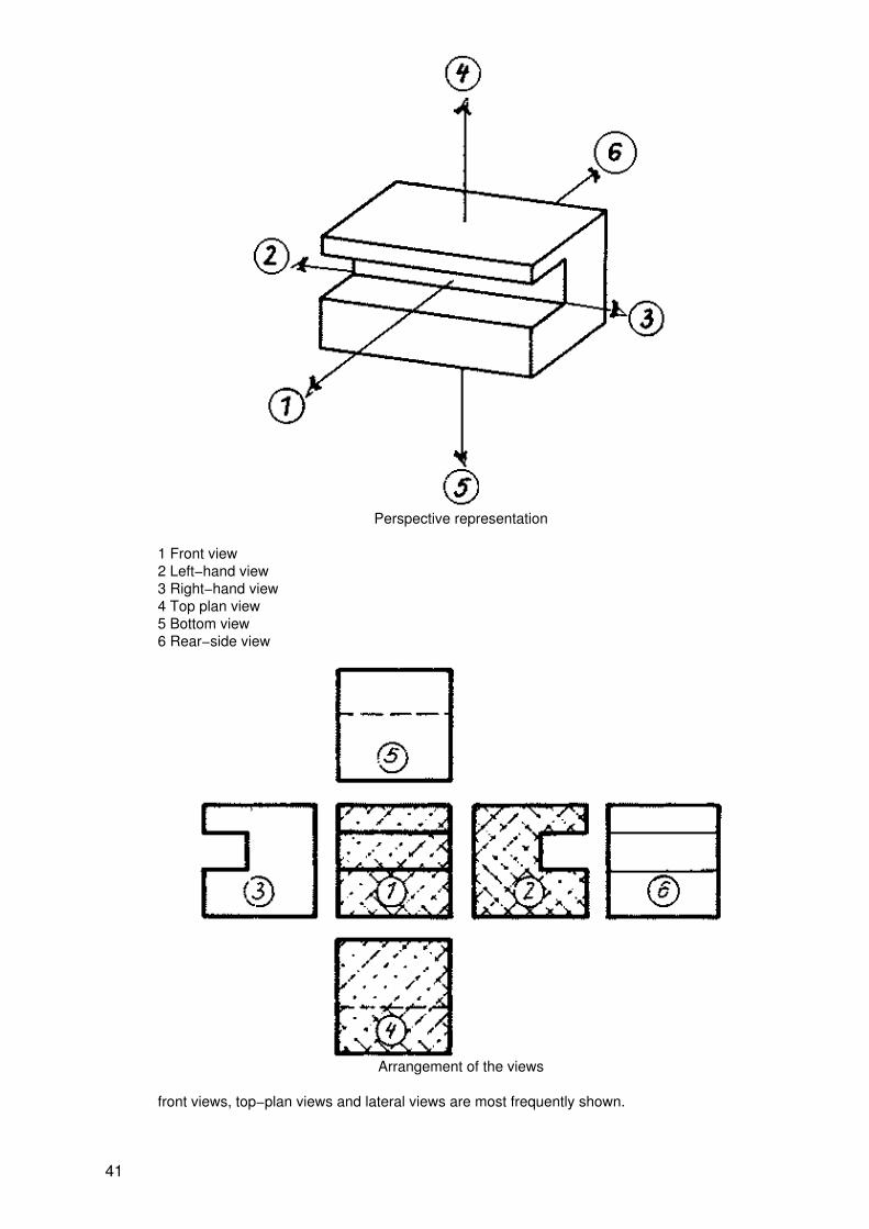
Perspective representation
1 Front view2 Left−hand view3 Right−hand view4 Top plan view5 Bottom view6 Rear−side view
Arrangement of the views
front views, top−plan views and lateral views are most frequently shown.
41

3.8. Figuring
3.8.1. Basic principles
Depending on its purpose, the drawing contains the figuring corresponding to the final state valid for theworkpiece. The following are used for figuring: dimension lines, reference lines, arrowheads, dimensionfigures. The following aspects in particular are decisive for figuring:
− The drawing should contain all dimensions required for the manufacturing of the workpiece
− Dimensions indicate the final condition of the workpiece
− Each dimension occurs only once
− Dimensions should be entered according to function and manufacture
− Function dimensions are tolerated
− Dimensions must be capable to being checked by workshop test equipment
− Dimensions resulting from manufacture are not entered
− Dimensions which are checked particularly well by the customer should be marked
− Figuring is done in millimetres, otherwiese the units should be entered after the dimensionfigure
3.8.2. Elements of figuring
Elements of figuring
M1 dimension figureM2 dimension lineM3 arrowheadM4 reference line
The dimension figures must be able to be read from below or from the right.
42
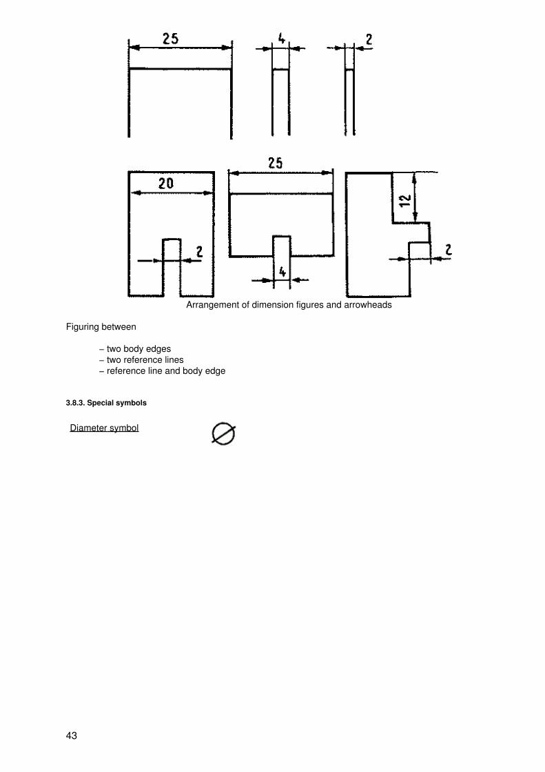
Arrangement of dimension figures and arrowheads
Figuring between
− two body edges− two reference lines− reference line and body edge
3.8.3. Special symbols
Diameter symbol
43

Symbol for circular crosssections entered before thedimension figure
Square symbol
Diagonal cross
Symbol for square crosssections, entered before thedimension figure.The diagonal cross marksquadrilateral plane areas
Radius symbol R
44

Symbol for roundings, enteredbefore the dimension figure
Sphere symbol, sphere
In the case of spherical shapesthe word sphere must beentered ahead of the diametersymbol
3.8.4. Notes on figuring
Dimensional reference system
Area − areaAxis − area
Two areas at right angles to each other are decisive forfunction
for symmetrical parts supported on one surface
Dimensional reference system
45
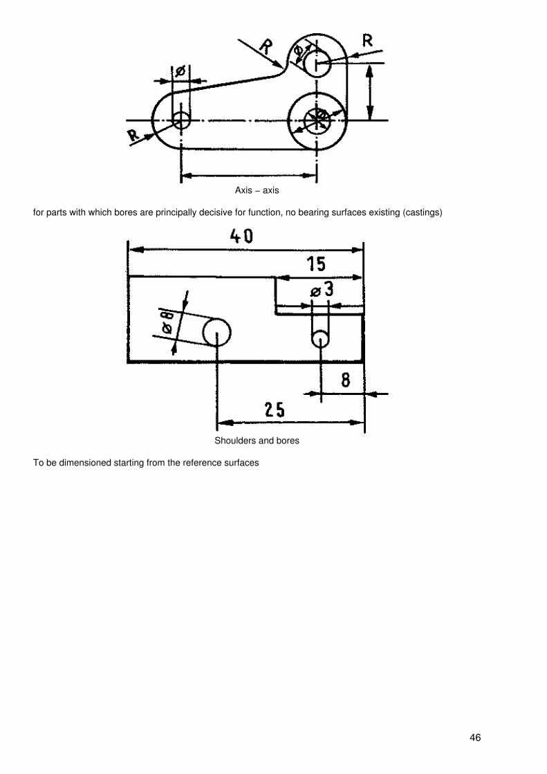
Axis − axis
for parts with which bores are principally decisive for function, no bearing surfaces existing (castings)
Shoulders and bores
To be dimensioned starting from the reference surfaces
46
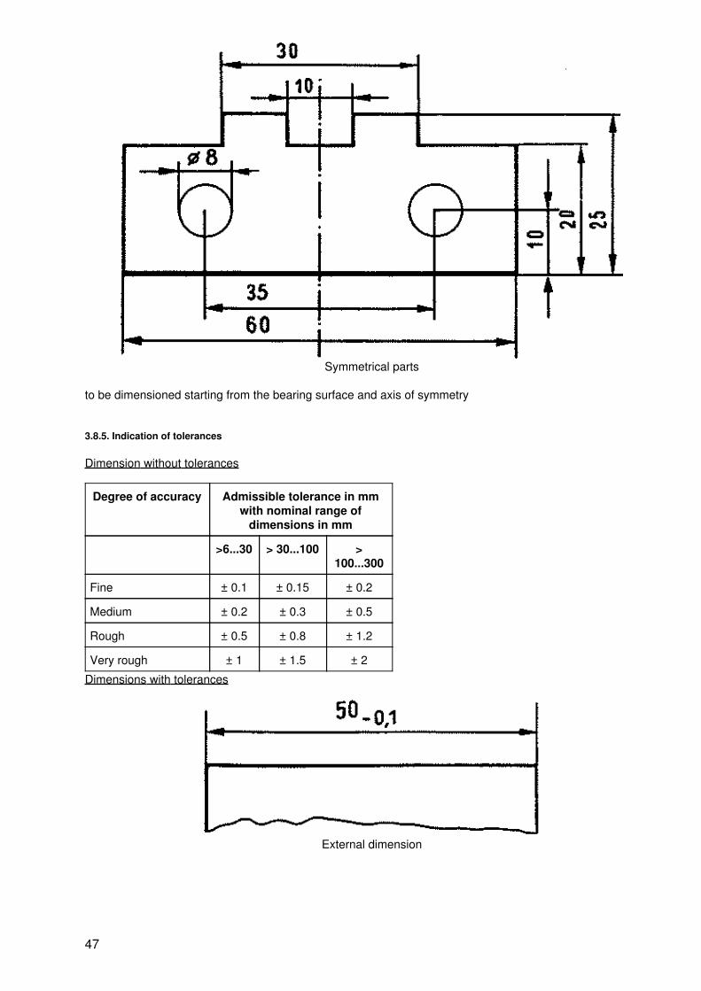
Symmetrical parts
to be dimensioned starting from the bearing surface and axis of symmetry
3.8.5. Indication of tolerances
Dimension without tolerances
Degree of accuracy Admissible tolerance in mmwith nominal range of
dimensions in mm
>6...30 > 30...100 >100...300
Fine ± 0.1 ± 0.15 ± 0.2
Medium ± 0.2 ± 0.3 ± 0.5
Rough ± 0.5 ± 0.8 ± 1.2
Very rough ± 1 ± 1.5 ± 2
Dimensions with tolerances
External dimension
47

Internal dimension
Spacing dimension
Angular dimension
3.9. Working and material characteristics
3.9.1. Surface characteristics
Symbol Explanation Manufacturing process
Optional manufacturing process casting, pressing, milling
Separation specified turning, filing, grinding
Operating process excluding separation forging, rolling
48

Example of figuring
3.9.2. Surface roughness
Medium roughness Rz inmm
Function Manufacturing process
160, 80 External surfaces which are not stressed chill casting
40 resting bearing surfaces precision pressing,milling
20 resting connecting and sliding surfaces (lowspeed)
finish drilling, finishmilling
10 sliding surfaces (medium speed) precision grinding
3.9.3. Material characteristics
Material Sectioning Material Sectioning
Metal (steel, cast steel, grey iron, copper) Wood
Non−metal (felt, fibre, rubber, leather, plastic) Sintered metal
Electric windings Brickwork
Transparent and translucent matter (glass, celluloid) Plain concrete
Liquids Earth
3.10. Sectional view
Use Representation
49
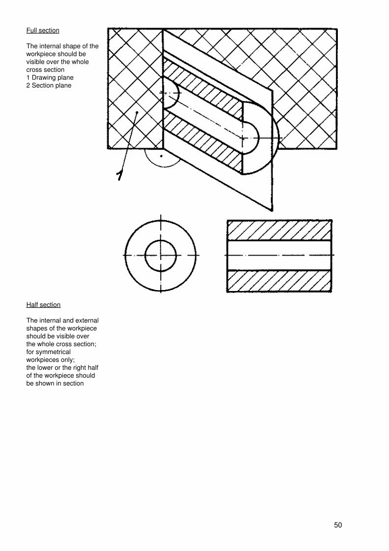
Full section
The internal shape of theworkpiece should bevisible over the wholecross section1 Drawing plane2 Section plane
Half section
The internal and externalshapes of the workpieceshould be visible overthe whole cross section;for symmetricalworkpieces only;the lower or the right halfof the workpiece shouldbe shown in section
50
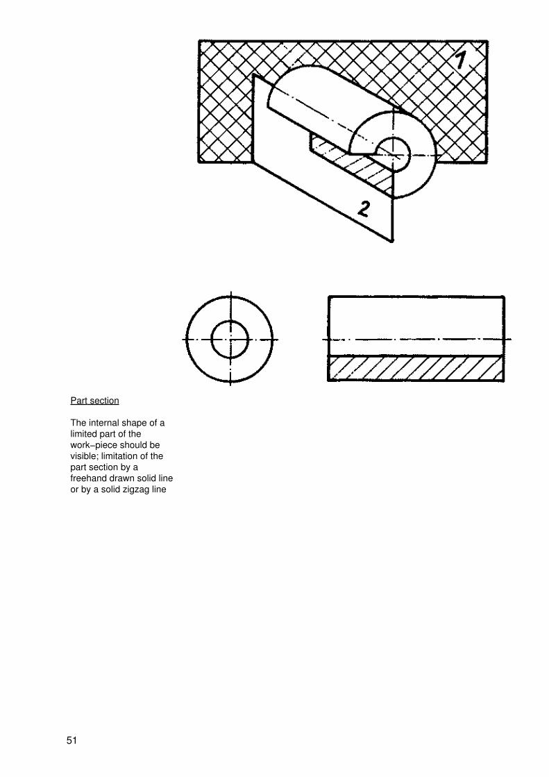
Part section
The internal shape of alimited part of thework−piece should bevisible; limitation of thepart section by afreehand drawn solid lineor by a solid zigzag line
51

3.11. Partial and interrupted representation
Type Examples
Partial representation
− with limitation by a narrowsolid zigzag line
− with limitation by a narrowfreehand drawn solid line
52
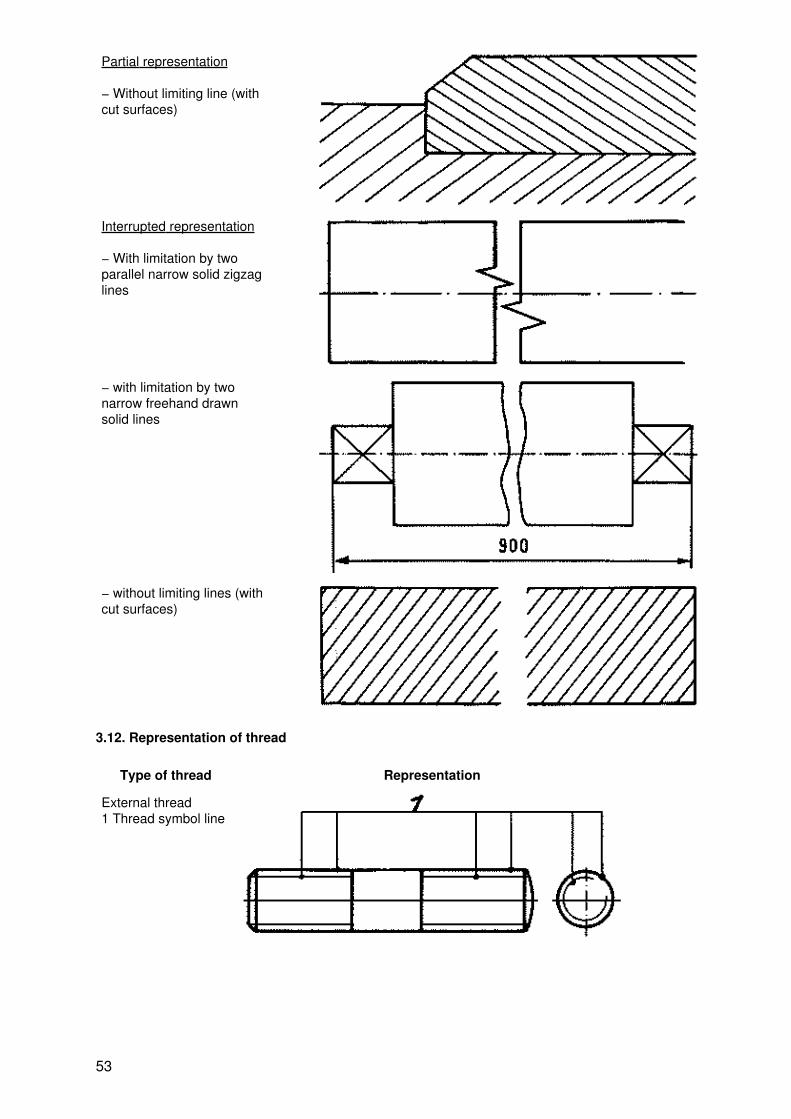
Partial representation
− Without limiting line (withcut surfaces)
Interrupted representation
− With limitation by twoparallel narrow solid zigzaglines
− with limitation by twonarrow freehand drawnsolid lines
− without limiting lines (withcut surfaces)
3.12. Representation of thread
Type of thread Representation
External thread1 Thread symbol line
53

Internal thread1 Thread symbol line
3.13. Simplified representation of holes and counterbores
Type Representation
Round through hole(hole diameter isindicated)
Tapped throughhole (thread symboland numericalvalue are indicated)
Round blind holeand threaded blindhole (Dimensionaldata aresupplemented bythe cylindrical depthof the hole and theeffective length ofthread,respectively)
Holes withtolerances(Tolerances to beindicated after thedimension)
54

Counterbores;conical orcylindrical(Diameter andangle of cone ordiameter and depthto be indicated afterthe dimension)
3.14. Simplified representation of disconnectable connections
3.14.1. Connecting elements
Connecting element Representation simplified symbol
Screw with hexagonhead and trunnion,thread not up to thehead
Cross−slotted screwwith fillister head
Screw with cylinderhead and transverseslot
Screw withcountersunk fillisterhead and transverseslot
55

Plain pin
Taper pin
Hexagon nut
Washer
Spring washer
3.14.2. Screw joints
Type of joint Representation simplified symbol
Screw joint with hexagon−head screw,washer and nut
56

Screw joint with cheese−head screw
Screw joint with countersunk screw
57

4. Metal materials
4.1. Characteristics
Characteristics of metals
Crystalline structure;
Metallic lustre;
Strength, formability (chipless),
Work−hardenability (highly temperature−dependent);
Good electric and thermal conductivity;
Decomposition in acids with the generation of salts;
Cations in aqueous metallic salt solutions;
Solid (crystalline) state at room temperature and normal pressures (with the exception of mercury)
4.2. Subdivision
Aspect Subdivision (examples)
General ferrous materialspure ironsteel (alloyed or unalloyed)cast iron
non−ferrousmaterials
According to density light metals(? < 5 g/cm3)aluminiummagnesium (or the corresponding alloys)
heavy metals(? > 5 g/cm3)ironcoppergold
Aspect Subdivision (examples)
58

according to melting point low melting(ts 900°C)lithiumtinlead
high−melting(ts 900...2000°C)silvercopperiron
very high−melting(ts 2000 °C)molybdenumtantalumtungsten
according to production melt−metallurgical(reguline metals
electrolytic power−metallurgical sinteredmetals, heavy base metalsexcept iron
according to colour ferrous metalsiron and its alloys
non−ferrous metalsleadzincnickel
according to chemicalproperties
precious metalsgoldsilverplatinum
base metalsaluminiumiron
4.3. Properties and use of important metals
Metal Symbol Density in103 kg/m3
Melting pointin °C
Aluminium Al 2.7 660
General (technological) properties
Whitish; a protective oxide film is formed on freshshoulders of cut which increases its resistance towear; relatively resistant to acids; lyes attack Alseriously; formed by drawing, spinning, pressuredeep−drawing, deep−drawing, forging, rolling; canbe welded, soldered or glued; metal−removingprocesses possible under certain circumstances(“lubrication”)
Use
Winding or cable wire, condenser foil in electricalengineering; foil for food packing; alumino−thermicwelding; with the addition of alloys in aircraft andvehicle construction.
Antimony Sb 6.68 630
General (technological) properties
Silver white, bright, very brittle, easily pulverizable;increases the hardness of alloys; toxic, resistant tohydrochloric acid and diluted sulphuric acid
Use
Only as alloying metal for babbitt bearings, hardlead, batteries, die cast products
Cadmium Cd 8.64 320.9
General (technological) properties
59

Bright, white; easily soluble in nitric acid, vapoursand soluble salts are toxic; soft, well formed byhammering, rolling, drawing
Use
For cadmium−plating; for the production oflow−melting alloys, fusible hard solder, batteries,bearing metals
Chromium Cr 7.19 1903
General (technological) properties
Silver white; very toxic, resistant to nitric acid, notresistant to diluted sulphuric acid; very hard andbrittle
Use
Alloying metal for iron materials (cutting metals andheavy−duty engineering components); coating metalfor surface protection
Cobalt Co 8.83 1495
General (technological) properties
Steel grey, bright; soluble in diluted oxidizing acids;great toughness and hardness, forgeable, magnetic
Use
Almost exclusively as alloying metal for hard metalsand tool steels; radioactive isotope for materialtesting
Copper Cu 8.93 1083
General (technological) properties
Light red; soluble in oxidizing acids, soluble coppercompounds are toxic; best electrical conductivityapart from silver, very soft, but tough and veryductile, properly formable without chip,metal−removal forming difficult (lubricant); can bebrazed, soldered and welded
Use
Wiring material in electrical engineering; material forboilers, heating tubes, cooling coils in the chemicalindustry; for galvanic cells; alloyed with zinc (brass),alloyed with tin (bronze)
Gold Au 19.28 1063
General (technological) properties
Yellow−red, bright, polishable, precious metal,extremely resistant to chemicals, not resistant tohalogens, calcium cyanide and aqua regia only; soft,greatest ductility of all metals, very well formed by
60
rolling, drawing, forging, hammering
Use
Alloyed with Ag, Cu, Pt, Pb and Ni for jewellery,dental material, precision−mechanical and opticalparts, electrical contacts, spinnerets
Iron Fe 7.87 1536
General (technological) properties
Bluish−white, polishable, easily magnetized; notresistant to humidity or water (formation of rust),soluble in diluted acids; high strength, corrosionresistance and resistance to scale by the addition ofalloying metals
Use
Wide field of application as steel, cast steel or castiron when adding alloying elements (e.g. carbon, Cr,Ni, Wo, Mo)
Lead Pb 11.34 327.4
General (technological) properties
Bluish−white fracture of silvery gloss,fine−grain; very toxic,resistant to sulphuric acid and hydrofluoric acid; verysoft easily cast, very well formed by rolling,hammering, pressing; cannot be drawn.
Use
Coating metal in tank construction (chemicalindustry); pipes and packing rings; lead paints, suchas white lead, red lead; radiation protection inmedicine; alloying metal for bearing materials; leadcable
Magnesium Mg 1.74 650
General (technological) properties
Silver white, bright; thin, dull−white oxide layer in theatmosphere, burns with a dazzling white flame (t 500°C), soluble in diluted acids, resistant to lyes;castable only with difficulty, easily worked when hot,well suited for forming by metal removal, (danger ofchip ignition!).
Use
Used in pyrotechnics; alloying element, especiallytogether with Al and Zn for vehicle construction andmechanical engineering.
Manganese Mn 7.21 1244
General (technological) properties
61

Silver white, steel−grey if containing carbon; easilysoluble in diluted acids, has a deoxidizing effect insteel and casting melts; very hard, brittle
Use
Exclusively as alloying element and deoxidant ofsteel; manganese steel for rails; all types ofheavy−duty components
Mercury Hg 13.55 38.87
General (technological) properties
Silver−white bright precious metal; liquid at roomtemperature, high surface tension, vapours andsoluble compounds highly toxic; insoluble in dilutedsulphuric and hydrochloric acid
Use
In thermometers, gas pressure gauges, electricswitches, high−vacuum pumps, mercury−vapourrectifiers, mercury−vapour lamps; for moulds in theproduction of precision components
Molybdenum Mo 10.2 2625
General (technological) properties
Silver white; very resistant, very ductile, very strong,easily formed by embossing, hammering, rolling,drawing
Use
Worked into sheets, tubes, bars and wires forelectron tubes and incandescent lamps; importantalloying element of steel; alloys with otherhigh−melting metals (Wo, Ta, Ti)
Nickel Ni 8.9 1455
General (technological) properties
bright white; resistant to water, air, alkalis, dilutedacids (except nitric acid); polishable, tough,ferromagnetic, easily formed by rolling, forging,drawing, weldable
Use
Carrier of oxide cathodes in radio valves; alloyingelement of steel (Cr, Ni steel); surface protection bynickel−plating
Platinum Pt 21.45 1733
General (technological) properties
Grey−white, bright precious metal; high solubility forhydrogen, resistant to oxygen and acids; veryductile, easily formed by hammering, rolling, drawing
62

Use
For the manufacture of laboratory equipment, wires,electrodes, galvanic cells, contacts in weak−currentengineering, catalyst in the chemical industry
Silicon Si 2.33 1412
General (technological) properties
Semi−metal; dark grey, bright or brown powder(depending on surface condition); easily soluble inlyes; very brittle, easily pulverizable
Use
Deoxidant; alloying element for steel (steels of highsilicon content with high resistance to acids), foraluminium and copper alloys
Silver Ag 10.5 960.8
General (technological) properties
White lustre, polishable, precious metal; easilysoluble in diluted nitric acid; very soft; the mostductile metal apart from gold, easily formed byhammering, forging, rolling, drawing; very goodconductor of heat and electric current
Use
Important mirror metal; for silver−plating andcladding; alloys for chemical equipment and surgicalinstruments
Tantalum Ta 16.67 2990
General (technological) properties
Grey, bright; soluble in a mixture of concentratednitric and hydrofluoric acid; very hard, extremelyductile, can be drawn to thin threads
Use
Chemical apparatuses, tantalum rectifiers andcapacitors, surgical auxiliary devices; alloyingelement for stainless steels and special steels;tantalum carbide for hard metal
Tin Sn 7.29 231.9
General (technological) properties
Silver white, bright; resistant to diluted organic acids;low hardness, high ductility, can be rolled, can bedrawn to wire at 100 °C; “tin cry” when bending a tinbar
Use
Coating metal; alloying element together with Pb and
63

Cu; important tin alloys; tin solders, tin bearingmetals
Titanium Ti 4.5 1690
General (technological) properties
Silver white, similar to steel; resistant to theatmosphere, soluble in hydrofluoric acid, verycorrosion−resistant; hard and brittle, forgeable onlywith red heat, cold rollable, high strength but lowweight
Use
Material for chemical plants; in the form of alloys withAl, Cr and V it is an important construction materialfor rocket and jet propulsion systems; alloyingelement for steel; titanium carbide for hard metal
Tungsten W 19.3 3380
General (technological) properties
White, metallic lustre; soluble in a mixture ofconcentrated nitric and hydrofluoric acid; ductile byhammering, can be drawn to wires
Use
Alloying element for special steels; for the productionof electric−lamp filaments, incandescent lamps andelectron tubes; for hevy−duty electrical contacts
Vanadium V 5.98 1730
General (technological) properties
Bluish grey, bright, resistant to the atmosphere,soluble in oxidizing acids; very hard, can behammered and rolled in its purest state
Use
Filter for X−rays; alloying element for tool steels(increases hardness and stability)
Zinc Zn 7.14 419.4
General (technological) properties
Bluish−white, very bright; surface oxidation in humidatmosphere, soluble in aqueous hydrochloric acid(soldering fluid); brittle at room temperature, can beformed without chips at high temperatures (90...200°C), pulverizable, easily cast, soldered and welded
Use
Sheets, strips, foils; extruded cups for dry elements;for galvanizing; for zinc paints; alloying element(brass, nickel silver)
64
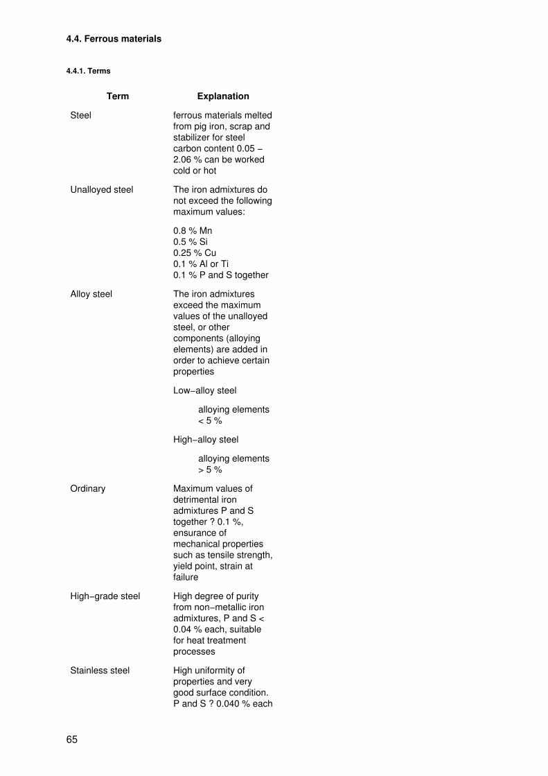
4.4. Ferrous materials
4.4.1. Terms
Term Explanation
Steel ferrous materials meltedfrom pig iron, scrap andstabilizer for steelcarbon content 0.05 −2.06 % can be workedcold or hot
Unalloyed steel The iron admixtures donot exceed the followingmaximum values:
0.8 % Mn0.5 % Si0.25 % Cu0.1 % Al or Ti0.1 % P and S together
Alloy steel The iron admixturesexceed the maximumvalues of the unalloyedsteel, or othercomponents (alloyingelements) are added inorder to achieve certainproperties
Low−alloy steel
alloying elements< 5 %
High−alloy steel
alloying elements> 5 %
Ordinary Maximum values ofdetrimental ironadmixtures P and Stogether ? 0.1 %,ensurance ofmechanical propertiessuch as tensile strength,yield point, strain atfailure
High−grade steel High degree of purityfrom non−metallic ironadmixtures, P and S <0.04 % each, suitablefor heat treatmentprocesses
Stainless steel High uniformity ofproperties and verygood surface condition.P and S ? 0.040 % each
65

Cast steel tough, forgeable, strongsteel for highly stressedcastings, cast intomoulds
Grey cast−iron Ferrous material frompig iron, cast iron scrapand scrap with thefollowing generalcomposition which iscast into moulds:
C = 2.8 − 3.5 %Si ? 3.8 %Mn ? 1.2 %P ? 1.0 %S ? 0.15 %not forgeable, greatrigidity and dampingproperty
Malleable cast−iron Material melted fromwhite pig iron whichbecomes forgeable byheat treatment(tempering) at 950 −1000 °C, duration oftreatment approx. 4 − 6days.
Chilled cast−iron hard and wear−resistantcast iron with thefollowing, generalcomposition:
C = 2.06 − 3 %Si = 0.4 − 1.2 %Mn = 0.8 − 1.3 %
White cast iron The casting is very hardthroughout
Chilled cast iron The casting is very hardon the surface only
4.4.2. Steel
Elements of symbols
Steel type or steel production
Symbol Meaning
C unalloyed high−grade and stainless steel
St unalloyed structural steel
W unalloyed tool steel (w at the end of the symbol)
X high−alloy steel
E electric steel
M open−hearth steel
66

T Thomas steel
W steel produced in a special process (W at the beginning of the symbol)
1 Grade 1, type of melting according to the producer’s own judgement (exception: St 38 S isproduced according to the Thomas process)
2 Grade 2, type of melting either according to the open−hearth process, the Ld process orthe improved Bessemer process
3 Grade 3, Ld process or open−hearth process; the steels are to be cast as non−ageingstructural steels, especially killed (e.g. using Al)
u Cast unkilled, gas formation during casting results in voids in the material
hb Cast semi−killed
b Cast killed, gas formation is prevented by the addition of metals (e.g. aluminium)
Heat treatment condition
Symbol Meaning Symbol Meaning
U Untreated S stress−relief annealed
G Soft annealed V hardened and tempered
N Normalized K + V Cold drawn and hardened and tempered
VÖ Oil treated K + G Cold drawn and soft−annealed
VL Tempered in air A Tempered
AS Quenched H + A Hardened and blown
Alloying component of low−alloy steels
Factor Alloying element
4 Al, Cr, Co, Cu, Mn, Ni, Si, W
10 Be, Mo, Nb, Ta, Ti, V
100 C, Ce, N, P, S
Scope of guarantee in the case of cast steel
Symbol Meaning
. 1 Yield point
. 2 Yield point and transverse bending test
. 3 Yield point and notched−bar impact strength
. 5 Yield point, notched−bar impact strength and transverse bending test
. 9 Magnetic induction
Examples of designation
Unalloyed structural steel:
Examples:
St 38 u − 2MSt 42 − 3
67
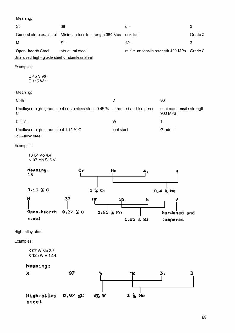
Meaning:
St 38 u − 2
General structural steel Minimum tensile strength 380 Mpa unkilled Grade 2
M St 42 − 3
Open−hearth Steel structural steel minimum tensile strength 420 MPa Grade 3
Unalloyed high−grade steel or stainless steel
Examples:
C 45 V 90C 115 W 1
Meaning:
C 45 V 90
Unalloyed high−grade steel or stainless steel; 0.45 %C
hardened and tempered minimum tensile strength900 MPa
C 115 W 1
Unalloyed high−grade steel 1.15 % C tool steel Grade 1
Low−alloy steel
Examples:
13 Cr Mo 4.4M 37 Mn Si 5 V
High−alloy steel
Examples:
X 97 W Mo 3.3X 125 W V 12.4
68
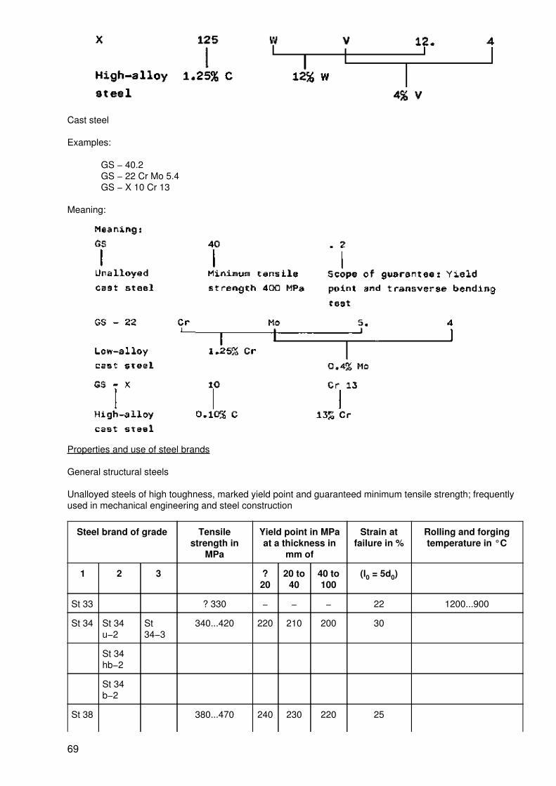
Cast steel
Examples:
GS − 40.2GS − 22 Cr Mo 5.4GS − X 10 Cr 13
Meaning:
Properties and use of steel brands
General structural steels
Unalloyed steels of high toughness, marked yield point and guaranteed minimum tensile strength; frequentlyused in mechanical engineering and steel construction
Steel brand of grade Tensilestrength in
MPa
Yield point in MPaat a thickness in
mm of
Strain atfailure in %
Rolling and forgingtemperature in °C
1 2 3 ?20
20 to40
40 to100
(l0 = 5d0)
St 33 ? 330 − − − 22 1200...900
St 34 St 34u−2
St34−3
340...420 220 210 200 30
St 34hb−2
St 34b−2
St 38 380...470 240 230 220 25
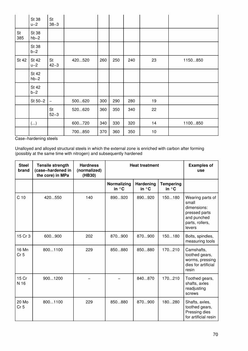
69
St 38u−2
St38−3
St385
St 38hb−2
St 38b−2
St 42 St 42u−2
St42−3
420...520 260 250 240 23 1150...850
St 42hb−2
St 42b−2
St 50−2 − 500...620 300 290 280 19
St52−3
520...620 360 350 340 22
(...) 600...720 340 330 320 14 1100...850
700...850 370 360 350 10
Case−hardening steels
Unalloyed and alloyed structural steels in which the external zone is enriched with carbon after forming(possibly at the same time with nitrogen) and subsequently hardened
Steelbrand
Tensile strength(case−hardened inthe core) in MPa
Hardness(normalized)
(HB30)
Heat treatment Examples ofuse
Normalizingin °C
Hardeningin °C
Temperingin °C
C 10 420...550 140 890...920 890...920 150...180 Wearing parts ofsmalldimensions:pressed partsand punchedparts, rollers,levers
15 Cr 3 600...900 202 870...900 870...900 150...180 Bolts, spindles,measuring tools
16 MnCr 5
800...1100 229 850...880 850...880 170...210 Camshafts,toothed gears,worms, pressingdies for artificialresin
15 CrN 16
900...1200 − − 840...870 170...210 Toothed gears,shafts, axlesreadjustingscrews
20 MoCr 5
800...1100 229 850...880 870...900 180...280 Shafts, axles,toothed gears,Pressing diesfor artificial resin
70

18 CrMn Ti5
950...1200 245 850...880 870...900 170...210 Toothed gears,shafts, axles
Quenched and subsequently tempered steels
Unalloyed and alloyed structural steels, whose toughness, tensile strength and yield point can be adapted tothe purpose of use by hardening (800 − 900 C) and subsequent tempering (530 − 670 °C)
Steelbrand
Hardened and tempered Tensilestrength in MPa at a diameter in
mm of
Minimumyield point
Softannealedhardness
Examples of use
16...40 40...100 100...160 in MPa in HB
C 60 750...900 700...850 − 450 229 Small parts of high tensilestrength: gear parts, shafts,lock components
30 Mn5
800...950 700...850 − 450 217 Low−stressed components:shafts, bolts, nuts, screws
37 MnSi 5
900...1100 800...950 700...850 450 229 Crankshafts, gear wheels,bolts, Cardan shafts
34 Cr 4 900...1100 800...950 700...850 450 197 Medium−stressedcomponents; gearcomponents
50 CrV4
1100...1300 900...1100 800...950 550 235 High−stressedcomponents; pinions,connecting rods
30 Cr 1250...1450 1100...1300 950...1150 700 248 High−stressed componentsof larger cross−sections
Steels resistant to pressurized hydrogen
heat−treatable steels whose resistance to pressurized hydrogen at operating temperature is ensured by theaddition of Cr, Mo, W, or V
Steel brand Tensile strength in MPa Resistance topressurized hydrogen
Examples of use
Pü in MPa t in °C
10 Cr Mo 9.10 450...600 32.5 400 Petroleum refining
16 Cr Mo 9.3 550...650 32.5 375 Welded high−pressurehollow bodies
24 Cr Mo 9 650...800 32.5 350 Regenerators, furnaceshells
17 Cr Mo W 11 650...800 32.5 480 High−pressure pipes,shaped parts
Unalloyed tool steels
High−purity steels with uniform hardening behaviour;mainly used for cold working tools (high surface quality and tough core)
Grade Steelbrand
Hardening inwaterin ° C
temperature inoil
in ° C
Examples of use
71

1 C 100 W1
760 to 790 to Milling cutters, reamers, cutting dies,thread cutting tools, cutting dies
C 110 W1
790 820
2 C 70 W 2 780 to 800 to Clamping screws and adjusting screws,embossing dies, milling cutters
C 90 W 2 810 830
3 C 60 W 3 780 to 800 to Hot dies, hot rolling, vice jaws andmachine jaws
C 75 W 3 810 830
− 780 to
810
Steels for specialpurposes
C 55 WS 800 to 830 − Hand saws, mill saws and circularsaws, anvils, axes
C 85 WS 780 to 810 790 to 820
Alloyed cold working steels
Tool steels for chipless or metal−removing shaping of materials, mainly when cold (room temperature)
Steel brand (example) Application group
125 Cr 1, 130 Cr 2, 140 Cr 2 Files
90 Mn V 8, 105 W Cr 6, 115 Cr V 3, 100 Cr 6 Thread cutting tools
37 W Cr V 7, 80 Cr V 3, X 90 Cr Mo V 18, 80 W Cr V 8 Mechanical cuttingblades
100 Cr 6, 110 Mo V5, 120 WV 4, 115 Cr V3, 115 W 8 Metal saws
35 W Cr V7, 45 Cr Si V6, 105 Mn Cr 4, 55 W Cr V7 Dies, punchers
140 Cr 2, 142 W Cr V 13, X 210 Cr 12 Drawing tools
90 Mn V8, 100 Cr 6, 145 Cr V 6, 105 Mn Cr 4 Measuring tools
Hot working steels
Tool steels for chipless or metal−removing forming of materials, mainly when hot (> 300 °C); the workingsurfaces are subject to great heat and frequent temperature change.
Steel brand Hardness whensoft−annealed
HB
Hardeningtemperature
in °C
Hardeningmedium
Examples of use
28 Cr Mo11.28
225 1030...1060 oil Extruding andspinning tools forheavy and lightmetals
37 Cr Mo WV20.15
225 980...1050 oil Extruding and hotupsetting tools
1000...1050 air
40 Ni Cr Mo15
265 820...850 oil Hot pressing dies forlight metals and Cu
72
alloys
850...870 air
45 Cr Mo V6.7
225 930...970 oil Die casting tools forlight metals
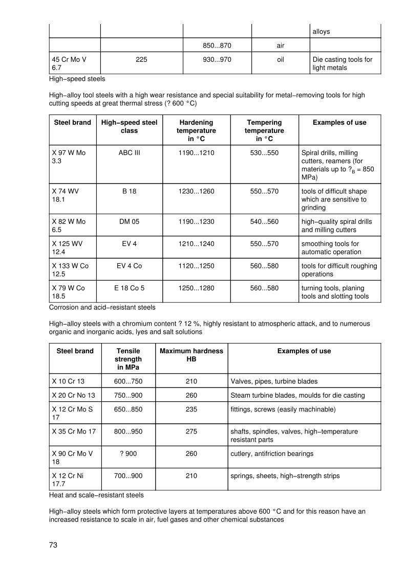
High−speed steels
High−alloy tool steels with a high wear resistance and special suitability for metal−removing tools for highcutting speeds at great thermal stress (? 600 °C)
Steel brand High−speed steelclass
Hardeningtemperature
in °C
Temperingtemperature
in °C
Examples of use
X 97 W Mo3.3
ABC III 1190...1210 530...550 Spiral drills, millingcutters, reamers (formaterials up to ?B = 850MPa)
X 74 WV18.1
B 18 1230...1260 550...570 tools of difficult shapewhich are sensitive togrinding
X 82 W Mo6.5
DM 05 1190...1230 540...560 high−quality spiral drillsand milling cutters
X 125 WV12.4
EV 4 1210...1240 550...570 smoothing tools forautomatic operation
X 133 W Co12.5
EV 4 Co 1120...1250 560...580 tools for difficult roughingoperations
X 79 W Co18.5
E 18 Co 5 1250...1280 560...580 turning tools, planingtools and slotting tools
Corrosion and acid−resistant steels
High−alloy steels with a chromium content ? 12 %, highly resistant to atmospheric attack, and to numerousorganic and inorganic acids, lyes and salt solutions
Steel brand Tensilestrengthin MPa
Maximum hardnessHB
Examples of use
X 10 Cr 13 600...750 210 Valves, pipes, turbine blades
X 20 Cr No 13 750...900 260 Steam turbine blades, moulds for die casting
X 12 Cr Mo S17
650...850 235 fittings, screws (easily machinable)
X 35 Cr Mo 17 800...950 275 shafts, spindles, valves, high−temperatureresistant parts
X 90 Cr Mo V18
? 900 260 cutlery, antifriction bearings
X 12 Cr Ni17.7
700...900 210 springs, sheets, high−strength strips
Heat and scale−resistant steels
High−alloy steels which form protective layers at temperatures above 600 °C and for this reason have anincreased resistance to scale in air, fuel gases and other chemical substances
73
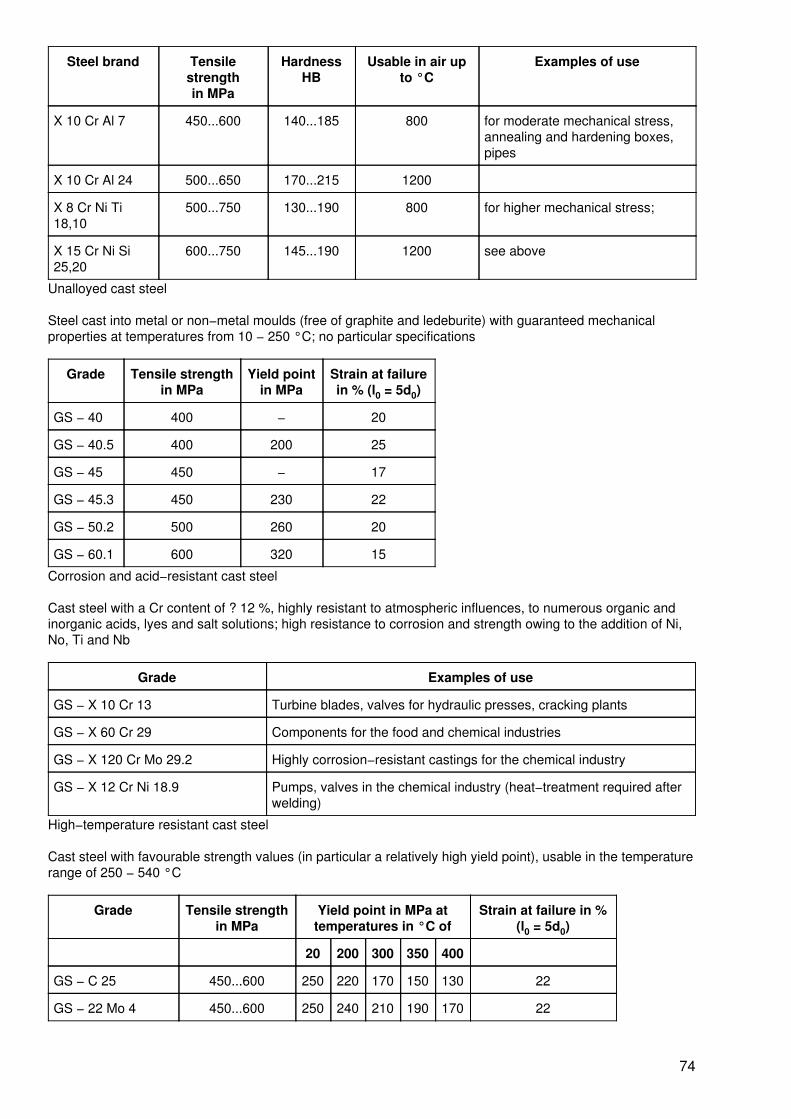
Steel brand Tensilestrengthin MPa
HardnessHB
Usable in air upto °C
Examples of use
X 10 Cr Al 7 450...600 140...185 800 for moderate mechanical stress,annealing and hardening boxes,pipes
X 10 Cr Al 24 500...650 170...215 1200
X 8 Cr Ni Ti18,10
500...750 130...190 800 for higher mechanical stress;
X 15 Cr Ni Si25,20
600...750 145...190 1200 see above
Unalloyed cast steel
Steel cast into metal or non−metal moulds (free of graphite and ledeburite) with guaranteed mechanicalproperties at temperatures from 10 − 250 °C; no particular specifications
Grade Tensile strengthin MPa
Yield pointin MPa
Strain at failurein % (l0 = 5d0)
GS − 40 400 − 20
GS − 40.5 400 200 25
GS − 45 450 − 17
GS − 45.3 450 230 22
GS − 50.2 500 260 20
GS − 60.1 600 320 15
Corrosion and acid−resistant cast steel
Cast steel with a Cr content of ? 12 %, highly resistant to atmospheric influences, to numerous organic andinorganic acids, lyes and salt solutions; high resistance to corrosion and strength owing to the addition of Ni,No, Ti and Nb
Grade Examples of use
GS − X 10 Cr 13 Turbine blades, valves for hydraulic presses, cracking plants
GS − X 60 Cr 29 Components for the food and chemical industries
GS − X 120 Cr Mo 29.2 Highly corrosion−resistant castings for the chemical industry
GS − X 12 Cr Ni 18.9 Pumps, valves in the chemical industry (heat−treatment required afterwelding)
High−temperature resistant cast steel
Cast steel with favourable strength values (in particular a relatively high yield point), usable in the temperaturerange of 250 − 540 °C
Grade Tensile strengthin MPa
Yield point in MPa attemperatures in °C of
Strain at failure in %(l0 = 5d0)
20 200 300 350 400
GS − C 25 450...600 250 220 170 150 130 22
GS − 22 Mo 4 450...600 250 240 210 190 170 22
74

GS − 22 Cr Mo 5.4 530...700 300 290 280 260 240 20
GS − 20 Mo V 8.4 600...800 340 350 320 310 290 15
4.4.3. Cast iron
Elements of symbols
Symbol Meaning
GGL Cast iron with lamellar graphite
GGG Cast iron with spheroidal graphite
− X High−alloy cast iron
GH White cast iron
GHK Chilled cast iron
GT Malleable cast iron (white or black)
GTW White malleable cast iron) ) previous
GTS Black malleable cast iron) ) symbols
GTP Pearlitic malleable cast iron) )
Properties and use of the cast iron grades
Gradeq
Tensile strength(min.)in MPa
Hardness (max.)HB
Examples of use
GGL − 00 − − Bench, gearing, columns
GGL − 25 250 245 Castings for mechanical engineering
GGG − 40 400 190 Couplings, housings, crankshafts, toothedgears
GGG − 50 500 240
GH − 200 − 300 Upper dies, lower dies, balls for mills
GH − 300 − ? 300
GHK − 400 − −
GT − 35 350 190 Spanners, keys, levers,
GT − 35E 350 220 Clamps differential casings rear axlehousings, gear−boxes, pressure levers
GT − 40E 400 220
GT − 45 450 200
GT − 65 650 250
4.5. Alloys of non−ferrous metals
4.5.1. Terms
Term Explanation
75
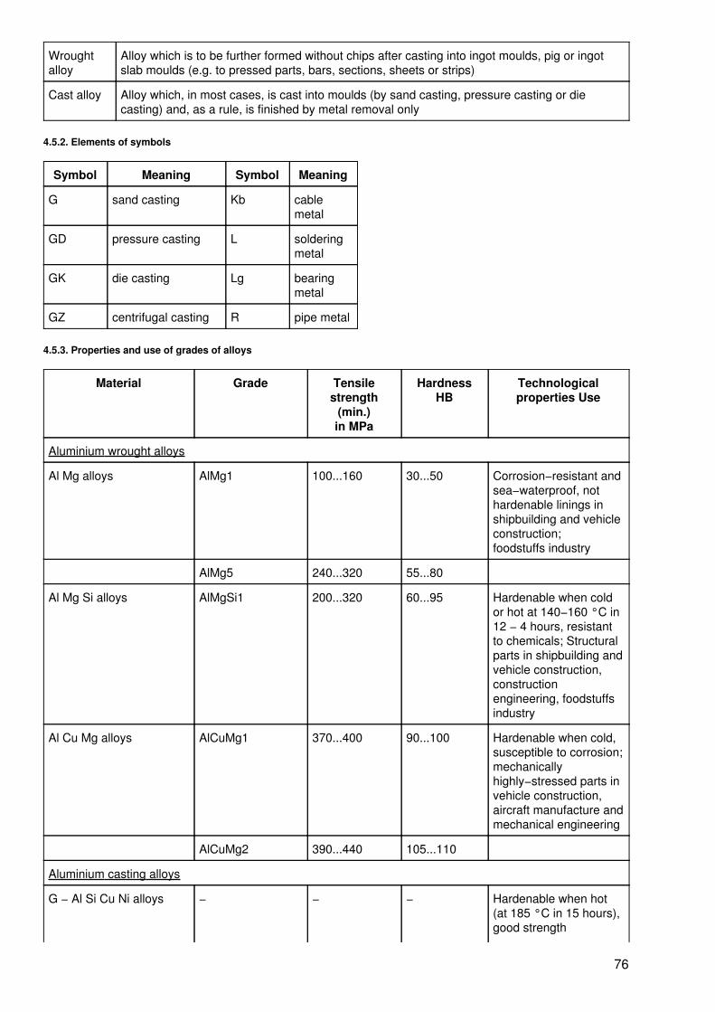
Wroughtalloy
Alloy which is to be further formed without chips after casting into ingot moulds, pig or ingotslab moulds (e.g. to pressed parts, bars, sections, sheets or strips)
Cast alloy Alloy which, in most cases, is cast into moulds (by sand casting, pressure casting or diecasting) and, as a rule, is finished by metal removal only
4.5.2. Elements of symbols
Symbol Meaning Symbol Meaning
G sand casting Kb cablemetal
GD pressure casting L solderingmetal
GK die casting Lg bearingmetal
GZ centrifugal casting R pipe metal
4.5.3. Properties and use of grades of alloys
Material Grade Tensilestrength
(min.)in MPa
HardnessHB
Technologicalproperties Use
Aluminium wrought alloys
Al Mg alloys AlMg1 100...160 30...50 Corrosion−resistant andsea−waterproof, nothardenable linings inshipbuilding and vehicleconstruction;foodstuffs industry
AlMg5 240...320 55...80
Al Mg Si alloys AlMgSi1 200...320 60...95 Hardenable when coldor hot at 140−160 °C in12 − 4 hours, resistantto chemicals; Structuralparts in shipbuilding andvehicle construction,constructionengineering, foodstuffsindustry
Al Cu Mg alloys AlCuMg1 370...400 90...100 Hardenable when cold,susceptible to corrosion;mechanicallyhighly−stressed parts invehicle construction,aircraft manufacture andmechanical engineering
AlCuMg2 390...440 105...110
Aluminium casting alloys
G − Al Si Cu Ni alloys − − − Hardenable when hot(at 185 °C in 15 hours),good strength
76
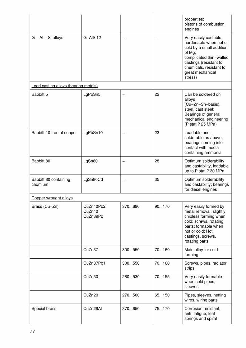
properties;pistons of combustionengines
G − Al − Si alloys G−AlSi12 − − Very easily castable,hardenable when hot orcold by a small additionof Mg;complicated thin−walledcastings (resistant tochemicals, resistant togreat mechanicalstress)
Lead casting alloys (bearing metals)
Babbitt 5 LgPbSn5 − 22 Can be soldered onalloys(Cu−Zn−Sn−basis),steel, cast steel;Bearings of generalmechanical engineering(P stat ? 25 MPa)
Babbitt 10 free of copper LgPbSn10 − 23 Loadable andsolderable as above;bearings coming intocontact with mediacontaining ammonia
Babbitt 80 LgSn80 − 28 Optimum solderabilityand castability, loadableup to P stat ? 30 MPa
Babbitt 80 containingcadmium
LgSn80Cd − 35 Optimum solderabilityand castability; bearingsfor diesel engines
Copper wrought alloys
Brass (Cu−Zn) CuZn40Pb2CuZn40CuZn39Pb
370...680 90...170 Very easily formed bymetal removal, slightlychipless forming whencold; screws, rotatingparts; formable whenhot or cold; Hotcastings, screws,rotating parts
CuZn37 300...550 70...160 Main alloy for coldforming
CuZn37Pb1 300...550 70...160 Screws, pipes, radiatorstrips
CuZn30 280...530 70...155 Very easily formablewhen cold pipes,sleeves
CuZn20 270...500 65...150 Pipes, sleeves, nettingwires, wiring parts
Special brass CuZn29Al 370...650 75...170 Corrosion resistant,anti−fatigue; leafsprings and spiral
77

springs
(Cu−Zn−...) CuZn21Al2 330...350 80...95 Sea−waterproof;condenser tubes,machine parts
Tin bronze CuSn2 260...370 55...100 Formable, slightlychipless;
(Cu−Sn) CuSn8 400...700 90...200 springs, screws
Multi−component tinbronze
CuSn4Zn4Pb4
320 70 Membranes, heatexchanger tubes,Bourdon tubes forpressure gauges
CuSn6Zn6 400...750 100...215
Nickel brass CuNi12Zn30Pb
500...600 150...175 Medical and precisioninstruments,table−plates
(Cu−Ni−Zn) CuNi18 520...620 155...180
Zn19Pb
Aluminium bronze(Cu−Al)
CuAl5 320...450 75...125 Acid−resistant,equipment for thechemical industry
Copper casting alloys
Cast tin bronze (Cu−Sn) G−CuSn10 − − Good sliding properties,resistant to alkalis, heatresistant up to 180 °C
Cast multi−component G−CuSn10Zn5
− − Tenacious,wear−resistant, averagesliding properties
tin bronze and G−CuSn6 − − Heat resistant up to 200°C, high wearresistance
red brass Zn7Pb4
(Cu−Sn−Zn...) G−CuZn33Pb2
− − Fittings, housings,construction parts
Cast multi−componentaluminium bronze(Cu−Al−...)
G−CuAl10Fe3Mn2
− − High corrosionresistance and wearresistance
Cast multi−componentaluminium bronze(Cu−Al−...)
G−CuAl9Ni4Fe4Mu2
− − Bearings for highestrequirements on slidingproperties and surfacepressures (compositecasting with protectivesteel skin)
G−CuPb22Sn5 − − Good sliding andantifrictional properties;Bearings with maximumsurface pressures andlow running speeds
Zinc casting alloys
78

G−ZnAl4 250 70 Components with highrequirements ondimensional stability
G−ZnAl6 180 80 Castings which aredifficult to cast
GK−Zn 220 80
Al6Cu1
Tin alloys
Soft solders (Sn − Pb − b) LSn25 − − Solder for flamesoldering
LSn30 − − surfacer soldering
LSn50 − − general solderingpurposes
LSn60 − − Tin−plating of wire inelectrical engineering
4.6. Hard metals
4.6.1. Term
Hard metals contain tungsten, titanium and vanadium carbide and cobalt, nickel and molybdenum as bindingagents; they are presintered (pressing with subsequent heat treatment), worked to shape and then finallysintered (at 1500 − 1900° C); used as cutting tools and for drawing tools, wire drawing dies and mining tools;cutting tips are brazed on basic bodies of low−alloy steel.
4.6.2. Properties and use of hard metals
Properties
Grade Densityin g/cm3
HardnessHRC
Identification colour Cutting conditions, properties of thehard metal
HS 01 6.1 − 6.4 91.5 − 93.0 blue increasing cutting speed feed possible
HS 02 9.9 − 10.2 91.5 − 93.0
HS 10 11.1 − 11.4 90.8 − 92.3
HS 20 11.2 − 11.5 90.0 − 91.5
HS 30 13.2 − 13.5 89.3 − 90.8
HS 40 13.1 − 13.4 88.6 − 90.1
HS 50 12.8 − 13.1 87.8 − 89.3
HU 10 12.6 − 12.9 90.8 − 92.7 yellow ?‘ ?‘
HU 30 12.8 − 13.1 90.0 − 91.5
HU 40 13.6 − 13.4 87.5 − 89.0
HG 01 14.9 − 15.2 91.5 − 93.0 red
HG 10 14.6 − 14.9 90.5 − 92.0
HG 15 14.9 − 15.2 90.5 − 91.5
79
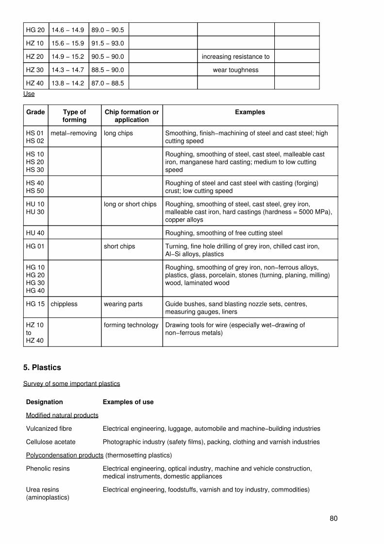
HG 20 14.6 − 14.9 89.0 − 90.5
HZ 10 15.6 − 15.9 91.5 − 93.0
HZ 20 14.9 − 15.2 90.5 − 90.0 increasing resistance to
HZ 30 14.3 − 14.7 88.5 − 90.0 wear toughness
HZ 40 13.8 − 14.2 87.0 − 88.5
Use
Grade Type offorming
Chip formation orapplication
Examples
HS 01HS 02
metal−removing long chips Smoothing, finish−machining of steel and cast steel; highcutting speed
HS 10HS 20HS 30
Roughing, smoothing of steel, cast steel, malleable castiron, manganese hard casting; medium to low cuttingspeed
HS 40HS 50
Roughing of steel and cast steel with casting (forging)crust; low cutting speed
HU 10HU 30
long or short chips Roughing, smoothing of steel, cast steel, grey iron,malleable cast iron, hard castings (hardness = 5000 MPa),copper alloys
HU 40 Roughing, smoothing of free cutting steel
HG 01 short chips Turning, fine hole drilling of grey iron, chilled cast iron,Al−Si alloys, plastics
HG 10HG 20HG 30HG 40
Roughing, smoothing of grey iron, non−ferrous alloys,plastics, glass, porcelain, stones (turning, planing, milling)wood, laminated wood
HG 15 chippless wearing parts Guide bushes, sand blasting nozzle sets, centres,measuring gauges, liners
HZ 10toHZ 40
forming technology Drawing tools for wire (especially wet−drawing ofnon−ferrous metals)
5. Plastics
Survey of some important plastics
Designation Examples of use
Modified natural products
Vulcanized fibre Electrical engineering, luggage, automobile and machine−building industries
Cellulose acetate Photographic industry (safety films), packing, clothing and varnish industries
Polycondensation products (thermosetting plastics)
Phenolic resins Electrical engineering, optical industry, machine and vehicle construction,medical instruments, domestic appliances
Urea resins(aminoplastics)
Electrical engineering, foodstuffs, varnish and toy industry, commodities)
80

Polymerization products (thermoplastics)
Polyvinyl chloride (PVC)
soft PVC Almost all branches of industry, chemical industry, building and packingindustries
rigid PVC Almost all branches of industry, chemical and consumer goods industry,electrical engineering
Polyethylene (PE) Chemical industry, packing industry, toys, unbreakable commodities
Polyamide (PA) Clothing industry, high−strength technical parts, unbreakable commodities,
Polymethacrylate Vehicle and aircraft construction, measuring and drawing instruments, dressjewellery
Polystyrene (PS) Weak−current engineering, toys, fashion goods
Polyacrylonitrile (PAN) High−strength weather, light and chemical−resistant fabrics
Polyaddition products
Polyurethane Wear−resistant technical parts and commodities, e.g. varnish, cast resins, elasticrubber materials, foamed plastics, adhesives, compression moulding material
Poly−utilization products
Unsaturated polyesterresins (PU)
For casting purposes and adhesion with fillers for moulded bodies
Epoxy resins (EP) Casting resins, adhesive resins and resin binders (casting together with fillers)
6. Semi−finished products of steel
6.1. Bars, strips, sheets
6.1.1. Square bar steel
Designation
a lateral lengthA cross−sectional aream weight
81
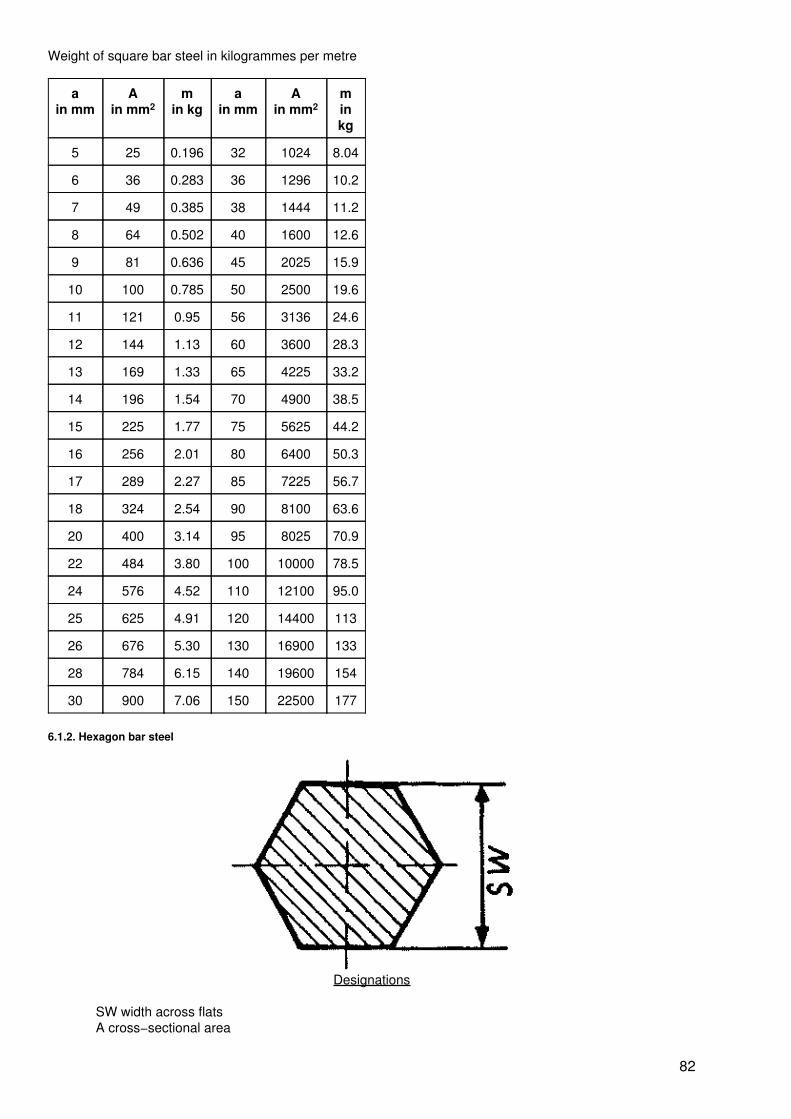
Weight of square bar steel in kilogrammes per metre
ain mm
Ain mm2
min kg
ain mm
Ain mm2
minkg
5 25 0.196 32 1024 8.04
6 36 0.283 36 1296 10.2
7 49 0.385 38 1444 11.2
8 64 0.502 40 1600 12.6
9 81 0.636 45 2025 15.9
10 100 0.785 50 2500 19.6
11 121 0.95 56 3136 24.6
12 144 1.13 60 3600 28.3
13 169 1.33 65 4225 33.2
14 196 1.54 70 4900 38.5
15 225 1.77 75 5625 44.2
16 256 2.01 80 6400 50.3
17 289 2.27 85 7225 56.7
18 324 2.54 90 8100 63.6
20 400 3.14 95 8025 70.9
22 484 3.80 100 10000 78.5
24 576 4.52 110 12100 95.0
25 625 4.91 120 14400 113
26 676 5.30 130 16900 133
28 784 6.15 140 19600 154
30 900 7.06 150 22500 177
6.1.2. Hexagon bar steel
Designations
SW width across flatsA cross−sectional area
82

m weight
Weight of hexagon bar steel in kilogrammes per metre
SWin mm
Ain mm2
min kg
SWin mm
Ain mm2
minkg
8 55.4 0.435 21 382 3.00
9 70.2 0.551 22 419 3.29
10 86.6 0.680 24 499 3.92
11 105 0.823 26 585 4.59
12 125 0.979 27 631 4.96
13 146 1.15 28 679 5.33
14 170 1.33 30 779 6.12
15 195 1.53 32 887 6.96
16 222 1.74 36 1122 8.81
17 249 1.96 41 1466 11.5
18 281 2.20 46 1833 14.4
19 313 2.45 50 2164 17.0
6.1.3. Round bar steel
Designations
d diameterA cross−sectional aream weight
Weight of round bar steel in kilogrammes per metre
din mm
Ain mm2
min kg
din mm
Ain mm2
minkg
5 19.63 0.154 38 1134 8.90
6 28.27 0.222 40 1257 9.87
6.5 33.18 0.260 42 1385 10.9
83

7 38.48 0.302 45 1590 12.5
8 50.24 0.395 48 1810 14.2
9 63.59 0.499 50 1964 15.4
10 78.54 0.617 53 2206 17.3
11 95.03 0.746 56 2463 19.3
12 113.1 0.888 60 2817 22.2
13 132.7 1.04 63 3117 24.5
14 153.9 1.21 65 3318 26.1
15 176.7 1.39 70 3848 30.2
16 201.1 1.58 75 4418 34.7
17 227.0 1.78 80 5027 39.5
18 254.5 2.0 85 5675 44.6
19 283.5 2.23 90 6362 49.9
20 314.2 2.47 95 7088 55.6
21 346.4 2.72 100 7854 61.7
22 380.1 2.98 105 8659 68.0
24 452.4 3.55 110 9503 74.6
25 490.9 3.85 120 11310 88.8
26 530.9 4.17 125 12270 96.3
28 615.8 4.83 130 13270 104
30 706.9 5.55 140 15390 121
32 804.2 6.31 150 17670 139
34 907.9 7.13 160 20110 158
36 1018 7.99 170 22700 178
6.1.4. Strip steel, flat steel, universal mill products and sheet steel
Designations
b widths thicknessm weight
84
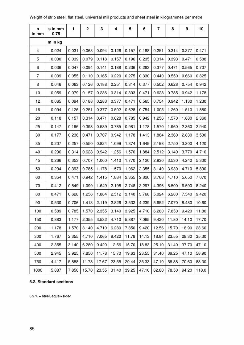
Weight of strip steel, flat steel, universal mill products and sheet steel in kilogrammes per metre
bin mm
s in mm0.75
1 2 3 4 5 6 7 8 9 10
m in kg
4 0.024 0.031 0.063 0.094 0.126 0.157 0.188 0.251 0.314 0.377 0.471
5 0.030 0.039 0.079 0.118 0.157 0.196 0.235 0.314 0.393 0.471 0.588
6 0.036 0.047 0.094 0.141 0.188 0.236 0.283 0.377 0.471 0.565 0.707
7 0.039 0.055 0.110 0.165 0.220 0.275 0.330 0.440 0.550 0.660 0.825
8 0.046 0.063 0.126 0.188 0.251 0.314 0.377 0.502 0.628 0.754 0.942
10 0.059 0.079 0.157 0.236 0.314 0.393 0.471 0.628 0.785 0.942 1.178
12 0.065 0.094 0.188 0.283 0.377 0.471 0.565 0.754 0.942 1.130 1.230
16 0.094 0.126 0.251 0.377 0.502 0.628 0.754 1.005 1.260 1.510 1.880
20 0.118 0.157 0.314 0.471 0.628 0.785 0.942 1.256 1.570 1.880 2.360
25 0.147 0.196 0.393 0.589 0.785 0.981 1.178 1.570 1.960 2.360 2.940
30 0.177 0.236 0.471 0.707 0.942 1.178 1.413 1.884 2.360 2.830 3.530
35 0.207 0.257 0.550 0.824 1.099 1.374 1.649 2.198 2.750 3.300 4.120
40 0.236 0.314 0.628 0.942 1.256 1.570 1.884 2.512 3.140 3.770 4.710
45 0.266 0.353 0.707 1.060 1.410 1.770 2.120 2.830 3.530 4.240 5.300
50 0.294 0.393 0.785 1.178 1.570 1.962 2.355 3.140 3.930 4.710 5.890
60 0.354 0.471 0.942 1.415 1.884 2.355 2.826 3.768 4.710 5.650 7.070
70 0.412 0.549 1.099 1.649 2.198 2.748 3.297 4.396 5.500 6.590 8.240
80 0.471 0.628 1.256 1.884 2.512 3.140 3.768 5.024 6.280 7.540 9.420
90 0.530 0.706 1.413 2.119 2.826 3.532 4.239 5.652 7.070 8.480 10.60
100 0.589 0.785 1.570 2.355 3.140 3.925 4.710 6.280 7.850 9.420 11.80
150 0.883 1.177 2.355 3.532 4.710 5.887 7.065 9.420 11.80 14.10 17.70
200 1.178 1.570 3.140 4.710 6.280 7.850 9.420 12.56 15.70 18.90 23.60
300 1.767 2.355 4.710 7.065 9.420 11.78 14.13 18.84 23.55 28.30 35.30
400 2.355 3.140 6.280 9.420 12.56 15.70 18.83 25.10 31.40 37.70 47.10
500 2.945 3.925 7.850 11.78 15.70 19.63 23.55 31.40 39.25 47.10 58.90
750 4.417 5.888 11.78 17.67 23.55 29.44 35.33 47.10 58.88 70.60 88.30
1000 5.887 7.850 15.70 23.55 31.40 39.25 47.10 62.80 78.50 94.20 118.0
6.2. Standard sections
6.2.1. − steel, equal−sided
85

Designations
b widths of legss thickness of legsr radii of curvature of the legsA cross−sectional aream weight
Weight of angle steel in kilogrammes per metre
(a × b × s) rin mm
Ain cm2
minkg
20 × 20 × 4 3.5 1.45 1.14
25 × 25 × 5 3.5 2.26 1.77
30 × 30 × 5 5 2.78 2.18
40 × 40 × 4 6 3.08 2.42
40 × 40 × 6 6 4.48 3.52
50 × 50 × 5 7 4.80 3.77
60 × 60 × 6 8 6.91 5.42
60 × 60 × 10 10 11.1 8.68
80 × 80 × 8 10 12.3 9.66
80 × 80 × 12 10 17.9 14.1
100 × 100 × 10 12 19.2 15.1
100 × 100 × 16 12 29.6 23.2
120 × 120 × 11 13 25.4 19.9
120 × 120 × 17 13 38.1 29.9
160 × 160 × 15 17 46.1 36.2
160 × 160 × 19 17 57.5 45.1
200 × 200 × 16 18 61.8 48.5
200 × 200 × 20 18 76.4 59.5
86

6.2.2. steel, unequal−sided
Designations
a width of the short legb width of the long legr radii of curvatureA cross−sectional aream weight
Weight of angle steel in kilogrammes per metre
(a × b × s) rin mm
Ain cm2
minkg
20 × 30 × 4 3.5 1.85 1.45
20 × 40 × 4 3.5 2.25 1.77
30 × 45 × 5 4.5 3.53 2.77
30 × 60 × 5 6.0 4.29 3.37
40 × 50 × 4 4.0 3.46 2.71
40 × 80 × 6 7.0 6.89 5.41
50 × 65 × 5 6.5 5.54 4.35
65 × 80 × 8 8 11.0 8.66
50 × 100 × 10 9.0 14.1 11.1
65 × 130 × 10 11 18.6 14.6
80 × 120 × 8 11 15.5 12.2
80 × 160 × 12 13 27.5 21.6
100 × 150 × 10 13 24.2 19.0
100 × 150 × 12 13 28.7 22.6
100 × 200 × 10 15 29.2 23.0
100 × 200 × 16 15 45.7 35.9
87

6.2.3. T−steel
Designations
h height of sectionb width of base
s thickness of web at a spacing r1, r2, r3 radiiA cross−sectional aream weight
Weight of T−steel in kilogrammes per metre
(b = h)mm
(s = t)mm
Ain cm2
min kg
(b = h)mm
(s = t)mm
Ain cm2
minkg
20 3 1.12 0.88 50 6 5.66 4.44
25 3.5 1.64 1.29 60 7 7.94 6.23
30 4 2.26 1.77 70 8 10.6 8.32
35 4.5 2.97 2.33 80 9 13.6 10.7
40 5 3.77 2.96 100 11 20.9 16.4
6.2.4. bar and shaped steel
88
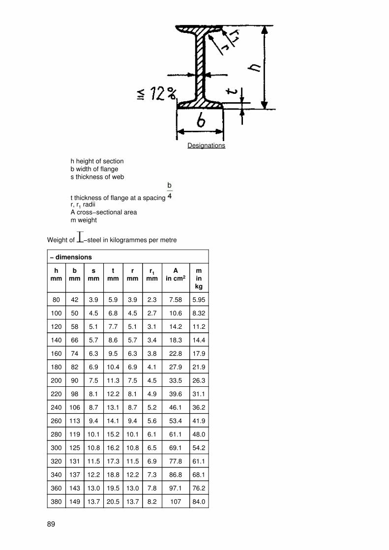
Designations
h height of sectionb width of flanges thickness of web
t thickness of flange at a spacingr, r1 radiiA cross−sectional aream weight
Weight of −steel in kilogrammes per metre
− dimensions
hmm
bmm
smm
tmm
rmm
r1mm
Ain cm2
minkg
80 42 3.9 5.9 3.9 2.3 7.58 5.95
100 50 4.5 6.8 4.5 2.7 10.6 8.32
120 58 5.1 7.7 5.1 3.1 14.2 11.2
140 66 5.7 8.6 5.7 3.4 18.3 14.4
160 74 6.3 9.5 6.3 3.8 22.8 17.9
180 82 6.9 10.4 6.9 4.1 27.9 21.9
200 90 7.5 11.3 7.5 4.5 33.5 26.3
220 98 8.1 12.2 8.1 4.9 39.6 31.1
240 106 8.7 13.1 8.7 5.2 46.1 36.2
260 113 9.4 14.1 9.4 5.6 53.4 41.9
280 119 10.1 15.2 10.1 6.1 61.1 48.0
300 125 10.8 16.2 10.8 6.5 69.1 54.2
320 131 11.5 17.3 11.5 6.9 77.8 61.1
340 137 12.2 18.8 12.2 7.3 86.8 68.1
360 143 13.0 19.5 13.0 7.8 97.1 76.2
380 149 13.7 20.5 13.7 8.2 107 84.0
89
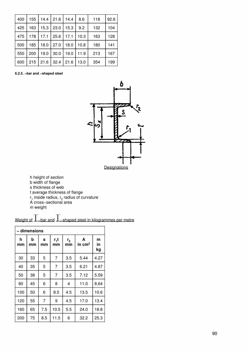
400 155 14.4 21.6 14.4 8.6 118 92.6
425 163 15.3 23.0 15.3 9.2 132 104
475 178 17.1 25.6 17.1 10.3 163 128
500 185 18.0 27.0 18.0 10.8 180 141
550 200 19.0 30.0 19.0 11.9 213 167
600 215 21.6 32.4 21.6 13.0 354 199
6.2.5. −bar and −shaped steel
Designations
h height of sectionb width of flanges thickness of webt average thickness of flanger1 inside radius, r2 radius of curvatureA cross−sectional aream weight
Weight of −bar and −shaped steel in kilogrammes per metre
− dimensions
hmm
bmm
smm
r1tmm
r2mm
Ain cm2
minkg
30 33 5 7 3.5 5.44 4.27
40 35 5 7 3.5 6.21 4.87
50 38 5 7 3.5 7.12 5.59
80 45 6 8 4 11.0 8.64
100 50 6 8.5 4.5 13.5 10.6
120 55 7 9 4.5 17.0 13.4
160 65 7.5 10.5 5.5 24.0 18.8
200 75 8.5 11.5 6 32.2 25.3
90

240 85 9.5 13 6.5 42.3 33.2
320 100 14 17.5 8.75 75.8 59.5
400 110 14 18 9 91.5 71.8
6.3. Steel pipes for water and gas lines
Designations
D outside diameters wall thicknessm weight
Weight of steel pipes for water and gas lines in kilogrammes per metre
Din mm
s in mm
1 1.5 2 2.5 3 3.5 4
m in kg
15 0.345 0.499 0.641 0.771 0.888 − −
16 0.370 0.536 0.690 0.832 0.962 1.08 1.16
18 0.419 0.610 0.789 0.956 1.11 1.25 1.38
20 0.469 0.684 0.888 1.08 1.26 1.42 1.58
22 0.518 0.758 0.962 1.20 1.41 − 1.77
25 0.592 0.869 1.13 1.39 1.63 1.86 2.07
28 0.666 0.980 1.28 1.57 1.85 2.11 2.37
30 0.715 1.05 1.38 1.70 2.00 2.29 2.56
32 0.764 1.13 1.48 1.82 2.15 2.46 2.76
35 0.838 1.24 1.63 2.00 2.37 2.72 3.06
38 − 1.35 1.78 2.19 2.59 2.98 3.35
40 0.962 1.42 1.87 2.31 2.74 − −
42 1.01 − 1.97 2.44 2.89 3.32 3.75
45 1.09 1.61 2.12 2.62 3.11 3.58 4.04
50 1.21 1.79 2.37 2.93 3.48 − 4.54
91
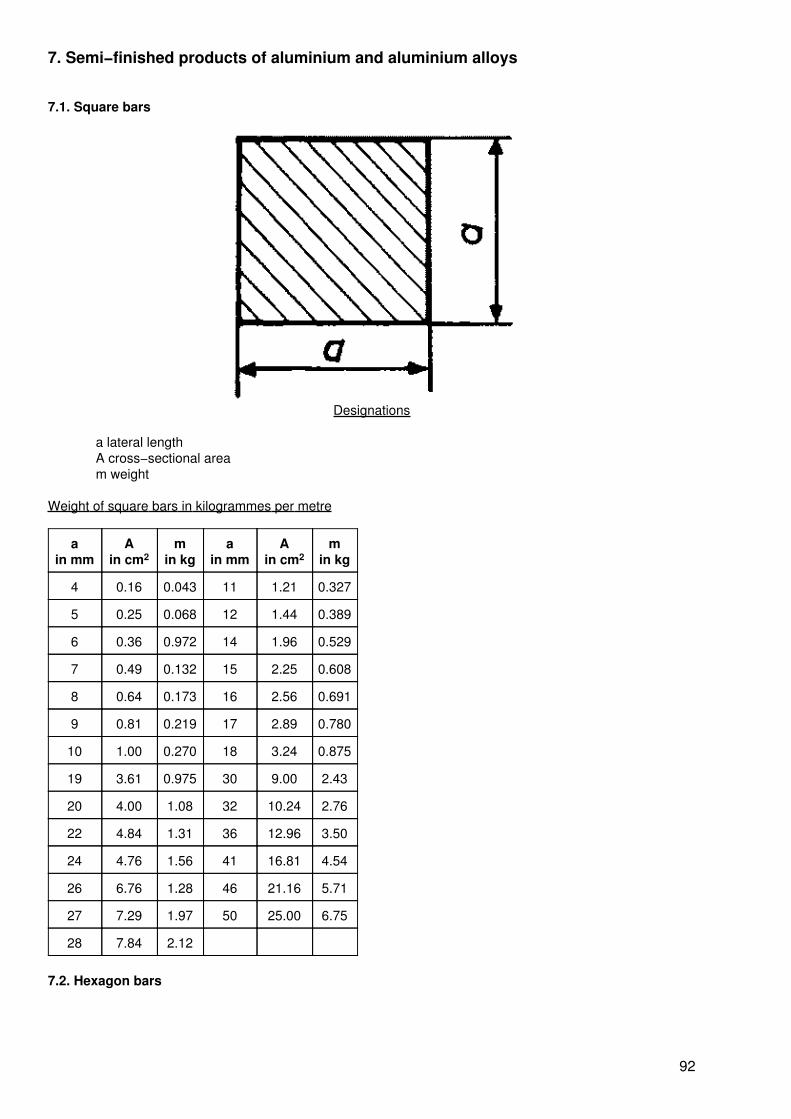
7. Semi−finished products of aluminium and aluminium alloys
7.1. Square bars
Designations
a lateral lengthA cross−sectional aream weight
Weight of square bars in kilogrammes per metre
ain mm
Ain cm2
min kg
ain mm
Ain cm2
min kg
4 0.16 0.043 11 1.21 0.327
5 0.25 0.068 12 1.44 0.389
6 0.36 0.972 14 1.96 0.529
7 0.49 0.132 15 2.25 0.608
8 0.64 0.173 16 2.56 0.691
9 0.81 0.219 17 2.89 0.780
10 1.00 0.270 18 3.24 0.875
19 3.61 0.975 30 9.00 2.43
20 4.00 1.08 32 10.24 2.76
22 4.84 1.31 36 12.96 3.50
24 4.76 1.56 41 16.81 4.54
26 6.76 1.28 46 21.16 5.71
27 7.29 1.97 50 25.00 6.75
28 7.84 2.12
7.2. Hexagon bars
92
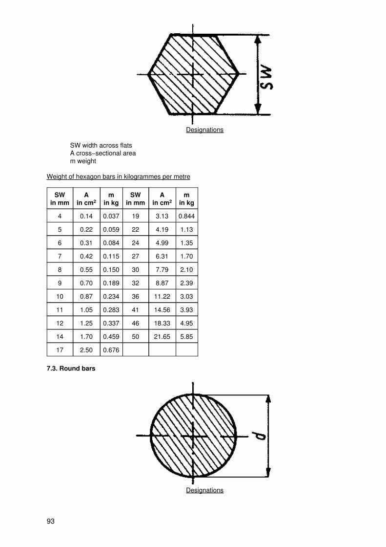
Designations
SW width across flatsA cross−sectional aream weight
Weight of hexagon bars in kilogrammes per metre
SWin mm
Ain cm2
min kg
SWin mm
Ain cm2
min kg
4 0.14 0.037 19 3.13 0.844
5 0.22 0.059 22 4.19 1.13
6 0.31 0.084 24 4.99 1.35
7 0.42 0.115 27 6.31 1.70
8 0.55 0.150 30 7.79 2.10
9 0.70 0.189 32 8.87 2.39
10 0.87 0.234 36 11.22 3.03
11 1.05 0.283 41 14.56 3.93
12 1.25 0.337 46 18.33 4.95
14 1.70 0.459 50 21.65 5.85
17 2.50 0.676
7.3. Round bars
Designations
93

d diameterA cross−sectional aream weight
Weight of round bars in kilogrammes per metre
din mm
Ain cm2
min kg
din mm
Ain cm2
min kg
2 0.031 0.008 18 2.55 0.687
2.5 0.049 0.013 19 2.84 0.766
3 0.071 0.019 20 3.14 0.848
3.5 0.096 0.026 21 3.46 0.935
4 0.126 0.034 22 3.80 1.03
5 0.196 0.053 24 4.52 1.22
5.5 0.238 0.064 25 4.91 1.33
6 0.283 0.076 26 5.13 1.43
6.5 0.332 0.090 27 5.73 1.55
7 0.385 0.104 28 6.15 1.66
7.5 0.442 0.119 29 6.61 1.78
8 0.503 0.136 30 7.07 1.91
8.5 0.586 0.153 32 8.04 2.17
9 0.636 0.172 33 8.55 2.31
9.5 0.701 0.191 34 9.08 2.45
10 0.785 0.212 35 9.62 2.60
12 1.13 0.305 38 11.34 3.06
13 1.33 0.358 40 12.57 3.39
14 1.54 0.416 42 13.85 3.7
15 1.77 0.477 45 15.90 4.2
16 2.01 0.543 48 18.1 4.8
17 2.27 0.613 50 19.6 5.3
8. Semi−finished products of copper and copper alloys
8.1. Square bars
94

Designations
a lateral lengthA cross−sectional aream weight
Weight of square bars in kilogrammes per metre
ain mm
Ain mm2
min kg
ain mm
Ain mm2
min kg
4 16 0.135 10 100 0.850
4.5 20.3 0.171 11 121 1.03
5 25 0.211 12 144 1.22
5.5 30.3 0.256 14 196 1.66
6 36 0.304 15 225 1.91
7 49 0.417 16 256 2.17
8 64 0.541 18 324 2.75
9 81 0.688 20 400 3.40
22 484 4.11 35 1230 10.45
24 576 4.90 36 1296 11.02
25 625 5.31 41 1681 14.30
26 676 5.75 46 2116 17.99
27 729 6.20 50 2500 21.25
30 900 7.65 55 3025 25.71
32 1024 8.70 60 3600 30.60
8.2. Hexagon bars
95
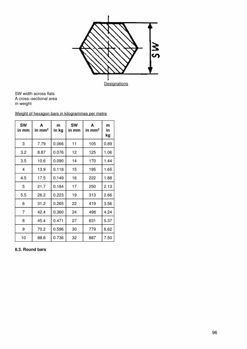
Designations
SW width across flatsA cross−sectional aream weight
Weight of hexagon bars in kilogrammes per metre
SWin mm
Ain mm2
min kg
SWin mm
Ain mm2
minkg
3 7.79 0.066 11 105 0.89
3.2 8.87 0.076 12 125 1.06
3.5 10.6 0.090 14 170 1.44
4 13.9 0.118 15 195 1.65
4.5 17.5 0.149 16 222 1.88
5 21.7 0.184 17 250 2.13
5.5 26.2 0.223 19 313 2.66
6 31.2 0.265 22 419 3.56
7 42.4 0.360 24 498 4.24
8 45.4 0.471 27 631 5.37
9 70.2 0.596 30 779 6.62
10 88.6 0.736 32 887 7.50
8.3. Round bars
96
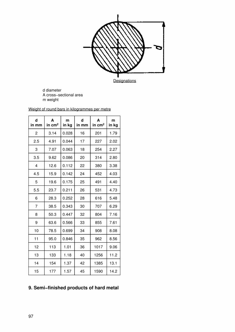
Designations
d diameterA cross−sectional aream weight
Weight of round bars in kilogrammes per metre
din mm
Ain cm2
min kg
din mm
Ain cm2
min kg
2 3.14 0.028 16 201 1.79
2.5 4.91 0.044 17 227 2.02
3 7.07 0.063 18 254 2.27
3.5 9.62 0.086 20 314 2.80
4 12.6 0.112 22 380 3.38
4.5 15.9 0.142 24 452 4.03
5 19.6 0.175 25 491 4.40
5.5 23.7 0.211 26 531 4.73
6 28.3 0.252 28 616 5.48
7 38.5 0.343 30 707 6.29
8 50.3 0.447 32 804 7.16
9 63.6 0.566 33 855 7.61
10 78.5 0.699 34 908 8.08
11 95.0 0.846 35 962 8.56
12 113 1.01 36 1017 9.06
13 133 1.18 40 1256 11.2
14 154 1.37 42 1385 13.1
15 177 1.57 45 1590 14.2
9. Semi−finished products of hard metal
97
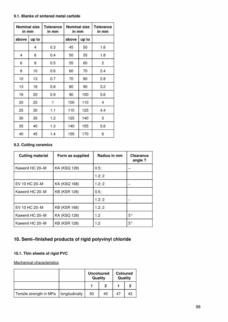
9.1. Blanks of sintered metal carbide
Nominal sizein mm
Tolerancein mm
Nominal sizein mm
Tolerancein mm
above up to above up to
4 0.3 45 50 1.6
4 6 0.4 50 55 1.8
6 8 0.5 55 60 2
8 10 0.6 60 70 2.4
10 13 0.7 70 80 2.8
13 16 0.8 80 90 3.2
16 20 0.9 90 100 3.6
20 25 1 100 110 4
25 30 1.1 110 125 4.4
30 35 1.2 125 140 5
35 40 1.3 140 155 5.6
40 45 1.4 155 170 6
9.2. Cutting ceramics
Cutting material Form as supplied Radius in mm Clearanceangle ?
Kawenit HC 20−M KA (KSQ 128) 0.5; −
1.2; 2
EV 10 HC 20−M KA (KSQ 168) 1.2; 2 −
Kawenit HC 20−M KB (KSR 128) 0.5;
1.2; 2 −
EV 10 HC 20−M KB (KSR 168) 1.2; 2
Kawenit HC 20−M KA (KSQ 128) 1.2 5°
Kawenit HC 20−M KB (KSR 128) 1.2 5°
10. Semi−finished products of rigid polyvinyl chloride
10.1. Thin sheets of rigid PVC
Mechanical characteristics
UncolouredQuality
ColouredQuality
1 2 1 2
Tensile strength in MPa longitudinally 50 45 47 42
98
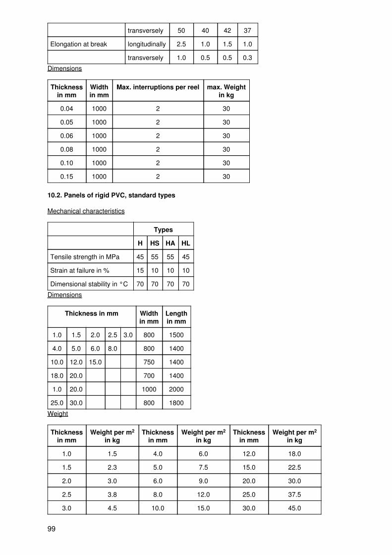
transversely 50 40 42 37
Elongation at break longitudinally 2.5 1.0 1.5 1.0
transversely 1.0 0.5 0.5 0.3
Dimensions
Thicknessin mm
Widthin mm
Max. interruptions per reel max. Weightin kg
0.04 1000 2 30
0.05 1000 2 30
0.06 1000 2 30
0.08 1000 2 30
0.10 1000 2 30
0.15 1000 2 30
10.2. Panels of rigid PVC, standard types
Mechanical characteristics
Types
H HS HA HL
Tensile strength in MPa 45 55 55 45
Strain at failure in % 15 10 10 10
Dimensional stability in °C 70 70 70 70
Dimensions
Thickness in mm Widthin mm
Lengthin mm
1.0 1.5 2.0 2.5 3.0 800 1500
4.0 5.0 6.0 8.0 800 1400
10.0 12.0 15.0 750 1400
18.0 20.0 700 1400
1.0 20.0 1000 2000
25.0 30.0 800 1800
Weight
Thicknessin mm
Weight per m2
in kgThickness
in mmWeight per m2
in kgThickness
in mmWeight per m2
in kg
1.0 1.5 4.0 6.0 12.0 18.0
1.5 2.3 5.0 7.5 15.0 22.5
2.0 3.0 6.0 9.0 20.0 30.0
2.5 3.8 8.0 12.0 25.0 37.5
3.0 4.5 10.0 15.0 30.0 45.0
99
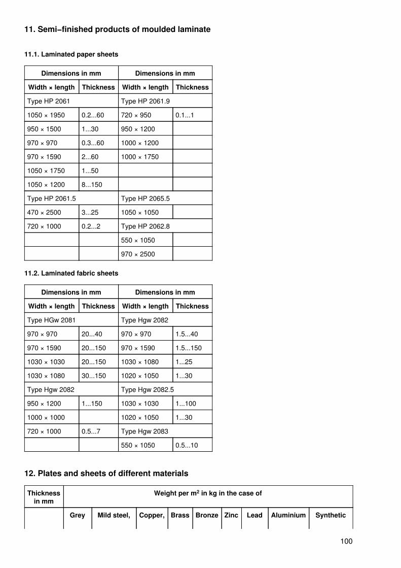
11. Semi−finished products of moulded laminate
11.1. Laminated paper sheets
Dimensions in mm Dimensions in mm
Width × length Thickness Width × length Thickness
Type HP 2061 Type HP 2061.9
1050 × 1950 0.2...60 720 × 950 0.1...1
950 × 1500 1...30 950 × 1200
970 × 970 0.3...60 1000 × 1200
970 × 1590 2...60 1000 × 1750
1050 × 1750 1...50
1050 × 1200 8...150
Type HP 2061.5 Type HP 2065.5
470 × 2500 3...25 1050 × 1050
720 × 1000 0.2...2 Type HP 2062.8
550 × 1050
970 × 2500
11.2. Laminated fabric sheets
Dimensions in mm Dimensions in mm
Width × length Thickness Width × length Thickness
Type HGw 2081 Type Hgw 2082
970 × 970 20...40 970 × 970 1.5...40
970 × 1590 20...150 970 × 1590 1.5...150
1030 × 1030 20...150 1030 × 1080 1...25
1030 × 1080 30...150 1020 × 1050 1...30
Type Hgw 2082 Type Hgw 2082.5
950 × 1200 1...150 1030 × 1030 1...100
1000 × 1000 1020 × 1050 1...30
720 × 1000 0.5...7 Type Hgw 2083
550 × 1050 0.5...10
12. Plates and sheets of different materials
Thicknessin mm
Weight per m2 in kg in the case of
Grey Mild steel, Copper, Brass Bronze Zinc Lead Aluminium Synthetic
100
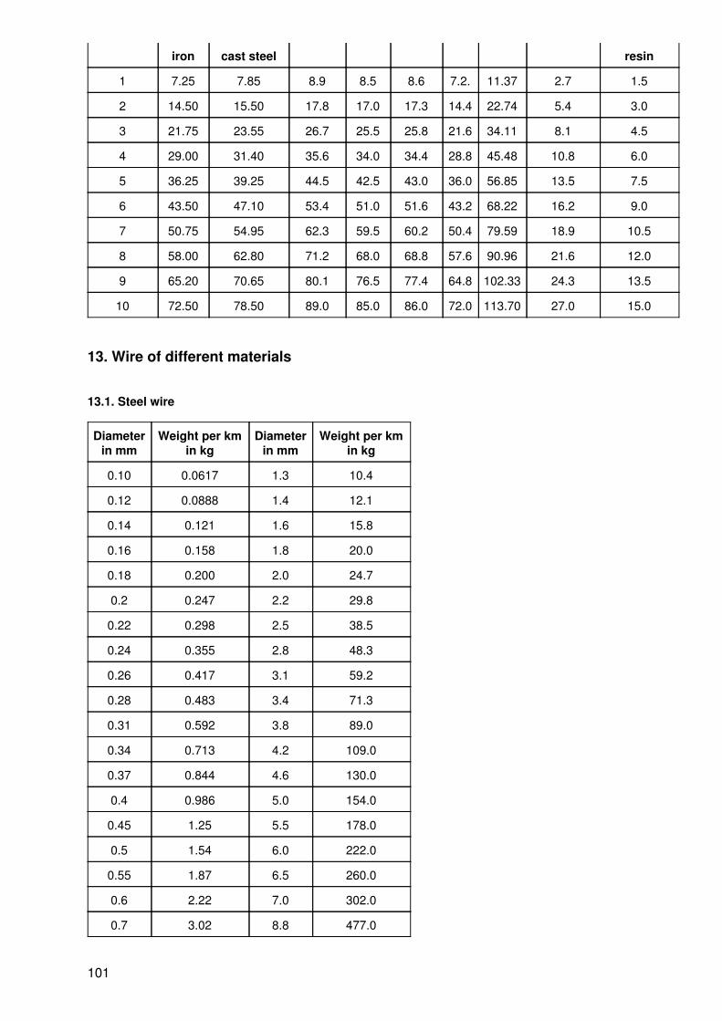
iron cast steel resin
1 7.25 7.85 8.9 8.5 8.6 7.2. 11.37 2.7 1.5
2 14.50 15.50 17.8 17.0 17.3 14.4 22.74 5.4 3.0
3 21.75 23.55 26.7 25.5 25.8 21.6 34.11 8.1 4.5
4 29.00 31.40 35.6 34.0 34.4 28.8 45.48 10.8 6.0
5 36.25 39.25 44.5 42.5 43.0 36.0 56.85 13.5 7.5
6 43.50 47.10 53.4 51.0 51.6 43.2 68.22 16.2 9.0
7 50.75 54.95 62.3 59.5 60.2 50.4 79.59 18.9 10.5
8 58.00 62.80 71.2 68.0 68.8 57.6 90.96 21.6 12.0
9 65.20 70.65 80.1 76.5 77.4 64.8 102.33 24.3 13.5
10 72.50 78.50 89.0 85.0 86.0 72.0 113.70 27.0 15.0
13. Wire of different materials
13.1. Steel wire
Diameterin mm
Weight per kmin kg
Diameterin mm
Weight per kmin kg
0.10 0.0617 1.3 10.4
0.12 0.0888 1.4 12.1
0.14 0.121 1.6 15.8
0.16 0.158 1.8 20.0
0.18 0.200 2.0 24.7
0.2 0.247 2.2 29.8
0.22 0.298 2.5 38.5
0.24 0.355 2.8 48.3
0.26 0.417 3.1 59.2
0.28 0.483 3.4 71.3
0.31 0.592 3.8 89.0
0.34 0.713 4.2 109.0
0.37 0.844 4.6 130.0
0.4 0.986 5.0 154.0
0.45 1.25 5.5 178.0
0.5 1.54 6.0 222.0
0.55 1.87 6.5 260.0
0.6 2.22 7.0 302.0
0.7 3.02 8.8 477.0
101

0.8 3.95 9.4 545.0
0.9 4.99 10.0 617.0
1.0 6.17
1.1 7.46
1.2 8.88
13.2. Copper or brass wire
Diameterin mm
Weight per kmin kg
Diameterin mm
Weight per kmin kg
copper brass copper brass
0.1 0.070 − 1.1. 18.458 8.078
0.12 0.101 − 1.2 10.066 9.613
0.15 0.157 − 1.3 11.810 11.282
0.18 0.226 − 1.4 13.697 13.085
0.2 0.280 0.267 1.5 15.727 15.020
0.22 0.338 0.323 1.6 17.898 17.090
0.25 0.437 0.417 1.7 20.201 19.293
0.28 0.548 0.523 1.8 22.650 21.630
0.3 0.629 0.601 1.9 25.231 24.100
0.32 0.716 0.684 2 27.963 26.704
0.35 0.856 0.818 2.1 30.830 29.441
0.38 1.009 0.964 2.2 33.828 32.311
0.4 1.118 1.068 2.3 36.979 35.315
0.45 1.415 1.352 2.4 40.264 38.453
0.5 1.747 1.667 2.5 43.690 41.724
0.55 2.114 2.019 3 62.914 60.083
0.6 2.615 2.403 3.5 85.626 81.780
0.65 2.953 2.821 4 111.838 106.821
0.7 3.425 3.271 4.5 141.546 155.186
0.75 3.932 3.775 5 174.731 166.951
0.8 4.474 4.273 5.5 211.446 201.946
0.85 5.051 4.832 6 251.638 240.323
0.9 5.662 6.024 7 342.508 527.117
1 6.990 6.676 8 447.358 427.257
102

14. Types and functions
Type Function Examples
Connectingelements
disconnectable and permanent connectionof structural members
bolts, screws, nuts washers, lockingscrews, pins, springs, keys, rivets
Supportingelements
supporting of structural members, receptionof forces
axles, sliding, antifriction bearings,frames, elastic springs
Transmittingelements
transmission, distribution, conversion ofmechanical energy
shafts, couplings, toothed gearings, beltdrives, trains of sprockets, crankmechanisms, worm gears, hydraulicgearings
Working elements Performance of the necessary workingmotions (rotating or straight−linereciprocating)
tools
Driving elements Provision of the required energy by energyconversion
electric motor, combustion engine
Control elements Control of energy and mass flow hand crank, hand wheel, switch
15. Connecting elements
15.1. Bolts
15.1.1. Bolts with heads
Representation Designation example
with split−pin hole
103

without split−pin hole
15.1.2. Bolts without heads
Representation Designation example
with split−pin holes
104
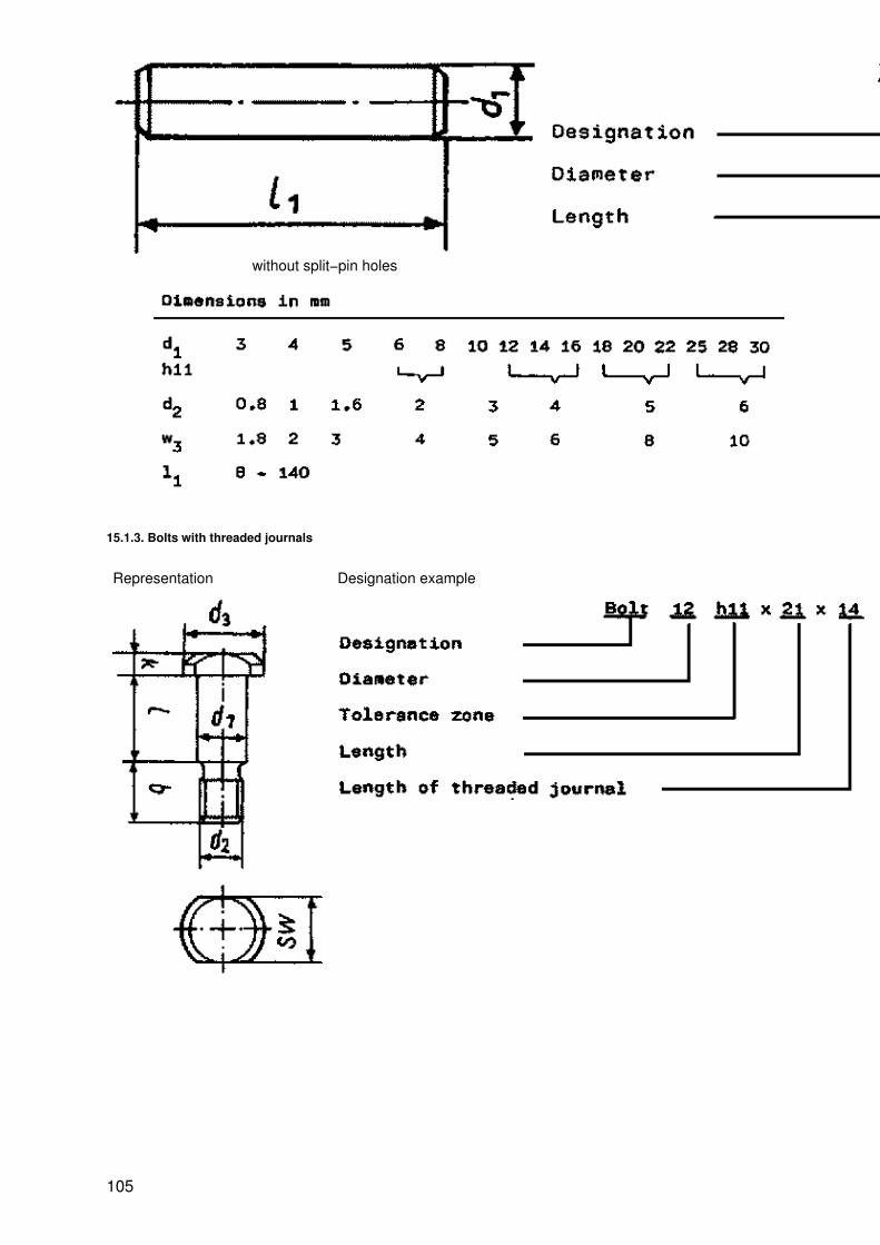
without split−pin holes
15.1.3. Bolts with threaded journals
Representation Designation example
105
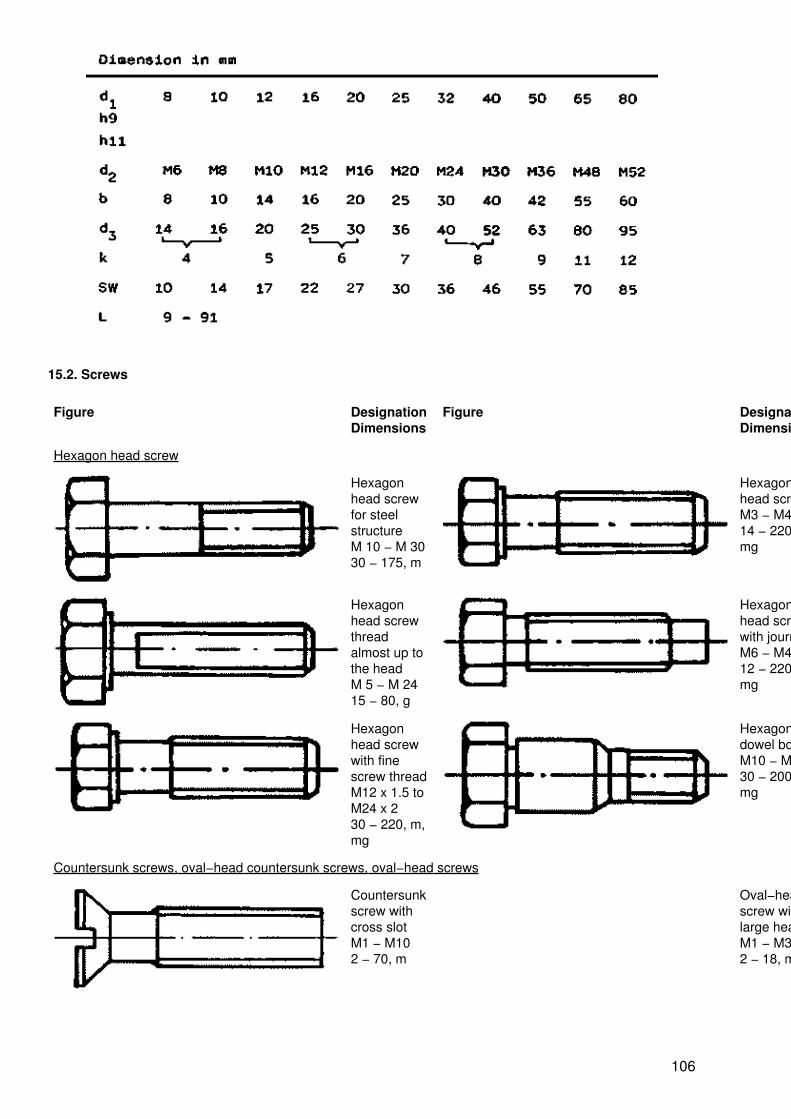
15.2. Screws
Figure DesignationDimensions
Figure DesignationDimensions
Hexagon head screw
Hexagonhead screwfor steelstructureM 10 − M 3030 − 175, m
Hexagonhead screwM3 − M4814 − 220, m,mg
Hexagonhead screwthreadalmost up tothe headM 5 − M 2415 − 80, g
Hexagonhead screwwith journalM6 − M4212 − 220, m,mg
Hexagonhead screwwith finescrew threadM12 x 1.5 toM24 x 230 − 220, m,mg
Hexagondowel boltM10 − M4830 − 200, m,mg
Countersunk screws, oval−head countersunk screws, oval−head screws
Countersunkscrew withcross slotM1 − M102 − 70, m
Oval−headscrew withlarge headM1 − M32 − 18, m
106
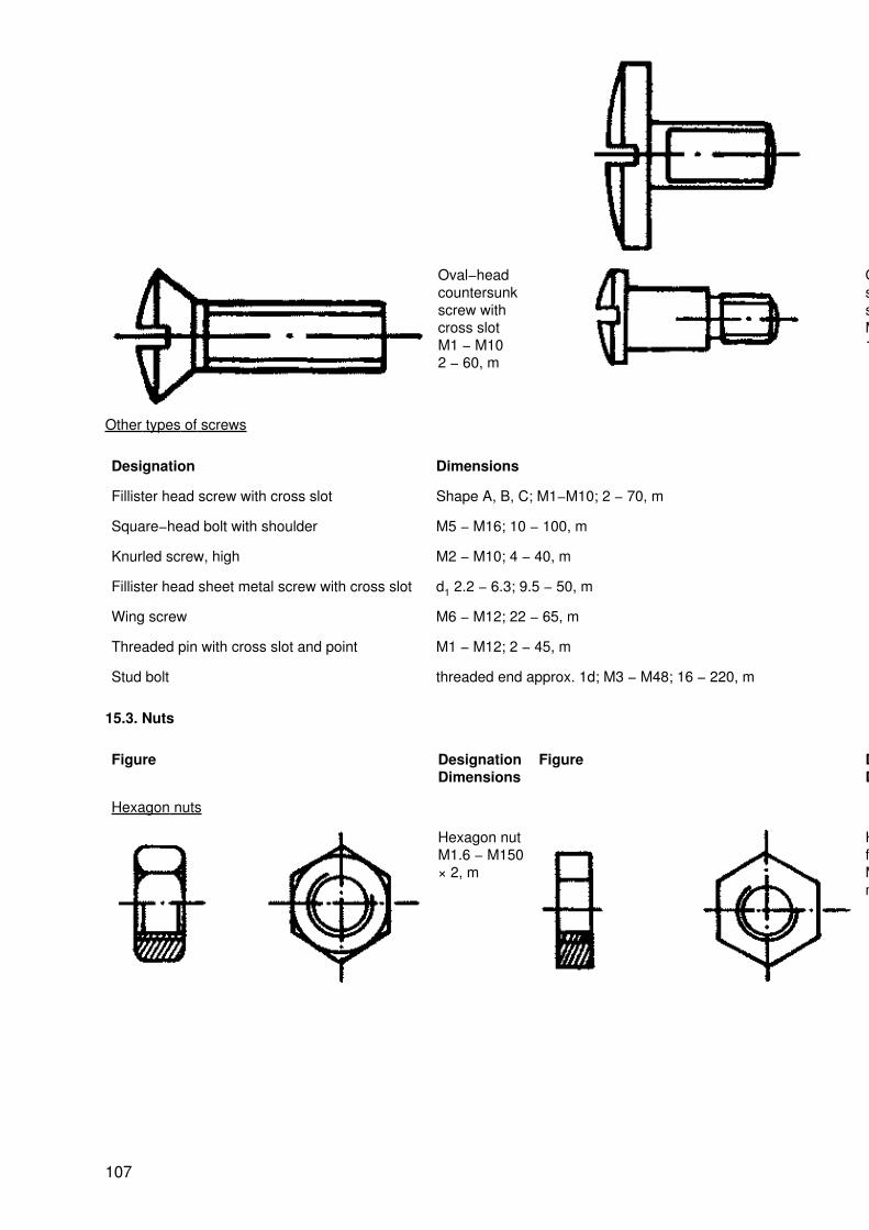
Oval−headcountersunkscrew withcross slotM1 − M102 − 60, m
Oval−headscrew withshoulderM1.6 − M101 − 25, m
Other types of screws
Designation Dimensions
Fillister head screw with cross slot Shape A, B, C; M1−M10; 2 − 70, m
Square−head bolt with shoulder M5 − M16; 10 − 100, m
Knurled screw, high M2 − M10; 4 − 40, m
Fillister head sheet metal screw with cross slot d1 2.2 − 6.3; 9.5 − 50, m
Wing screw M6 − M12; 22 − 65, m
Threaded pin with cross slot and point M1 − M12; 2 − 45, m
Stud bolt threaded end approx. 1d; M3 − M48; 16 − 220, m
15.3. Nuts
Figure DesignationDimensions
Figure DesignationDimensions
Hexagon nuts
Hexagon nutM1.6 − M150× 2, m
Hexagon nut,flatM1.6 − M30,m
107
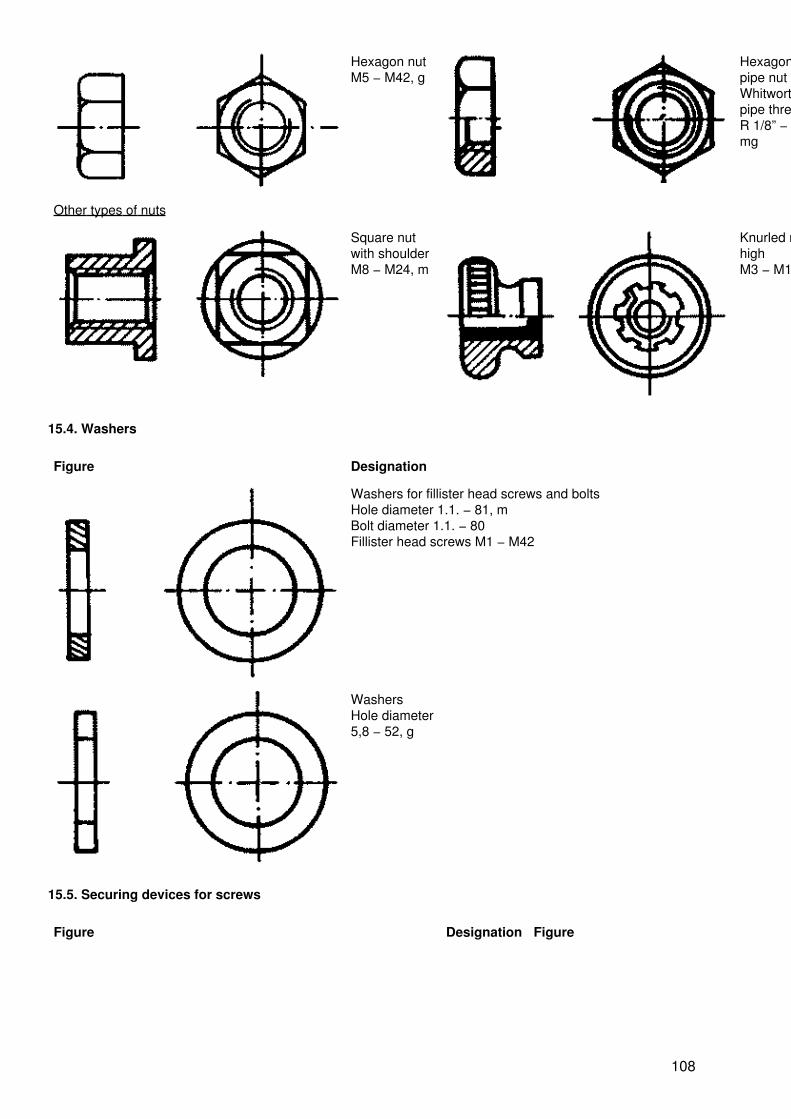
Hexagon nutM5 − M42, g
Hexagonpipe nutWhitworthpipe threadR 1/8” − R 6”,mg
Other types of nuts
Square nutwith shoulderM8 − M24, m
Knurled nut,highM3 − M10, m
15.4. Washers
Figure Designation
Washers for fillister head screws and boltsHole diameter 1.1. − 81, mBolt diameter 1.1. − 80Fillister head screws M1 − M42
WashersHole diameter5,8 − 52, g
15.5. Securing devices for screws
Figure Designation Figure Designation
108

Springwashersa) bent openb) smooth 2− 48, m
Lockingplates withinternal lugsd2 6−75da 16 − 95,m
Lockingplates withtangsd 3.2 − 50,m
Split pinsd 0,6 − 13l 4 − 180
15.6. Pins
15.6.1. Cylindrical pins
15.6.2. Taper pins
109
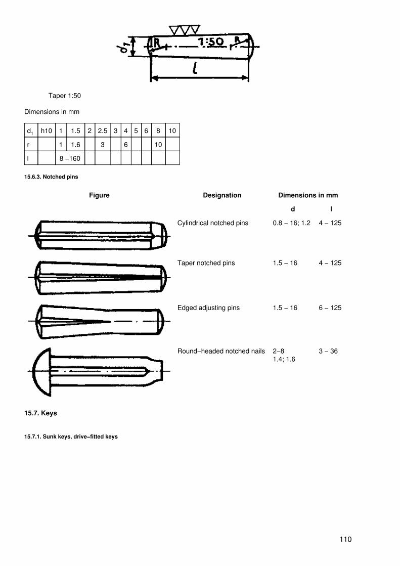
Taper 1:50
Dimensions in mm
d1 h10 1 1.5 2 2.5 3 4 5 6 8 10
r 1 1.6 3 6 10
l 8 −160
15.6.3. Notched pins
Figure Designation Dimensions in mm
d l
Cylindrical notched pins 0.8 − 16; 1.2 4 − 125
Taper notched pins 1.5 − 16 4 − 125
Edged adjusting pins 1.5 − 16 6 − 125
Round−headed notched nails 2−81.4; 1.6
3 − 36
15.7. Keys
15.7.1. Sunk keys, drive−fitted keys
110
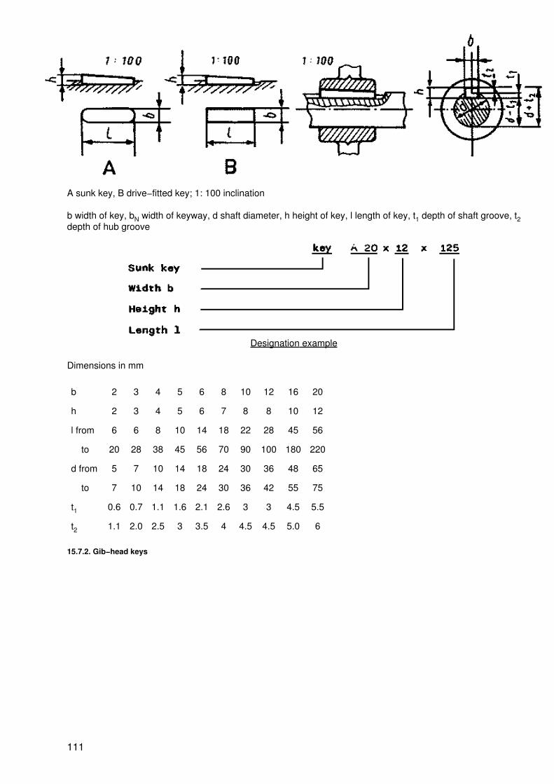
A sunk key, B drive−fitted key; 1: 100 inclination
b width of key, bN width of keyway, d shaft diameter, h height of key, l length of key, t1 depth of shaft groove, t2depth of hub groove
Designation example
Dimensions in mm
b 2 3 4 5 6 8 10 12 16 20
h 2 3 4 5 6 7 8 8 10 12
l from 6 6 8 10 14 18 22 28 45 56
to 20 28 38 45 56 70 90 100 180 220
d from 5 7 10 14 18 24 30 36 48 65
to 7 10 14 18 24 30 36 42 55 75
t1 0.6 0.7 1.1 1.6 2.1 2.6 3 3 4.5 5.5
t2 1.1 2.0 2.5 3 3.5 4 4.5 4.5 5.0 6
15.7.2. Gib−head keys
111
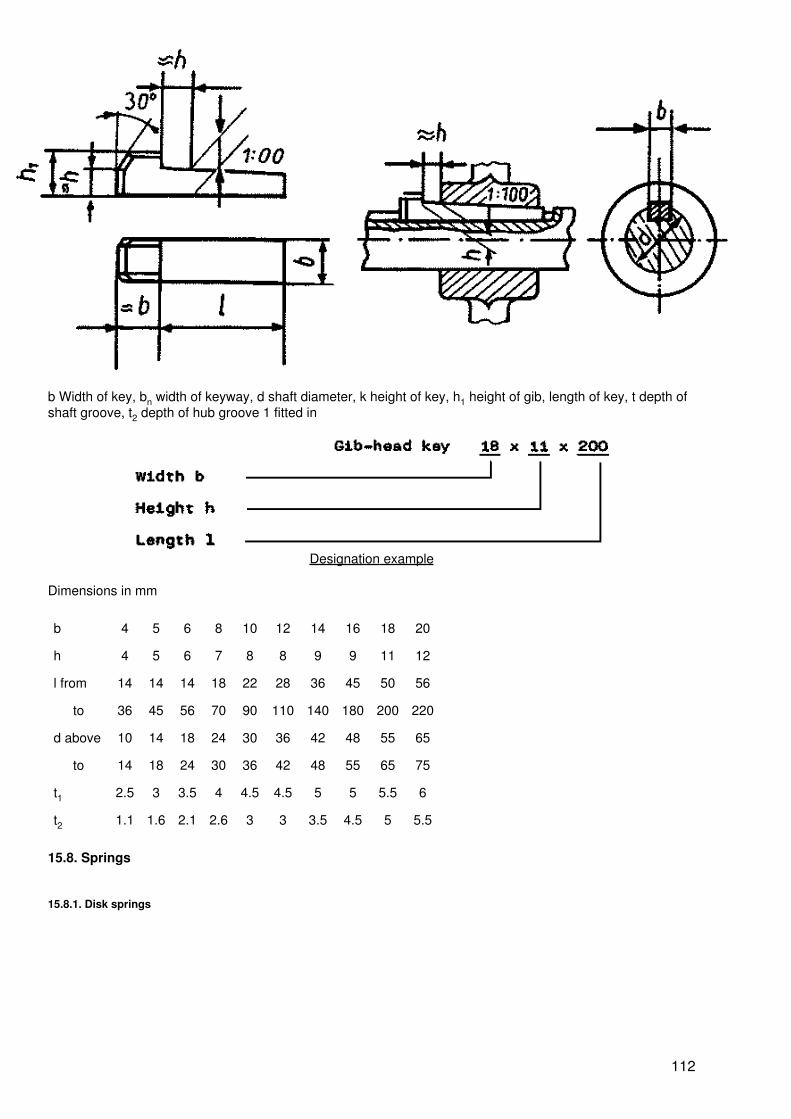
b Width of key, bn width of keyway, d shaft diameter, k height of key, h1 height of gib, length of key, t depth ofshaft groove, t2 depth of hub groove 1 fitted in
Designation example
Dimensions in mm
b 4 5 6 8 10 12 14 16 18 20
h 4 5 6 7 8 8 9 9 11 12
l from 14 14 14 18 22 28 36 45 50 56
to 36 45 56 70 90 110 140 180 200 220
d above 10 14 18 24 30 36 42 48 55 65
to 14 18 24 30 36 42 48 55 65 75
t1 2.5 3 3.5 4 4.5 4.5 5 5 5.5 6
t2 1.1 1.6 2.1 2.6 3 3 3.5 4.5 5 5.5
15.8. Springs
15.8.1. Disk springs
112
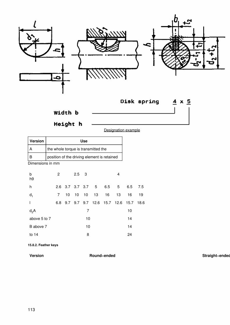
Designation example
Version Use
A the whole torque is transmitted the
B position of the driving element is retained
Dimensions in mm
bh9
2 2.5 3 4
h 2.6 3.7 3.7 3.7 5 6.5 5 6.5 7.5
d1 7 10 10 10 13 16 13 16 19
l 6.8 9.7 9.7 9.7 12.6 15.7 12.6 15.7 18.6
d2A 7 10
above 5 to 7 10 14
B above 7 10 14
to 14 8 24
15.8.2. Feather keys
Version Round−ended Straight−ended
113

withoutholdingscrew
Shape AShape B
withholdingscrew
Shape C
Shape D
with twoholdingscrewsandforcingscrews
Shape EShape F
Designation example
Dimensions in mm
b h9 2 3 4 5 6 8 10 12 16 20
114

h f3 2 3 4 5 6 7 8 8 10 12
l1 from 6 6 8 10 14 18 22 28 45 56
to 25 36 45 56 70 90 110 140 180 220
d1 above 5 7 10 14 18 24 30 36 48 65
to 7 10 14 18 24 30 36 42 55 75
15.9. Rivets
Figure Designation Dimensions inmm
d l
Rivets with buttonheads 1−9 2−60
Rivets with buttonheads for steelstructures
10 −30
16 −200
Countersunk−head rivets 1−9 2−60
Countersunk−head rivets 10 −30
20 −150
115
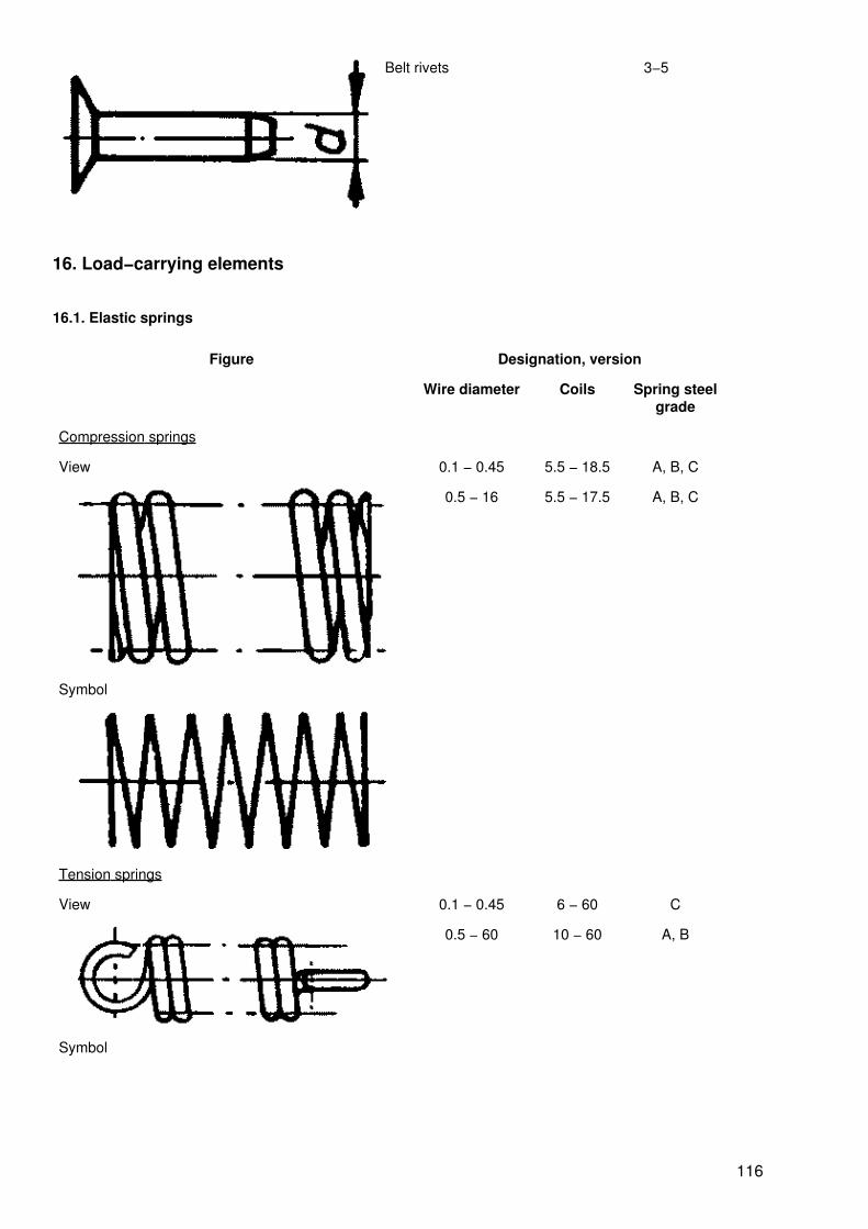
Belt rivets 3−5
16. Load−carrying elements
16.1. Elastic springs
Figure Designation, version
Wire diameter Coils Spring steelgrade
Compression springs
View 0.1 − 0.45 5.5 − 18.5 A, B, C
0.5 − 16 5.5 − 17.5 A, B, C
Symbol
Tension springs
View 0.1 − 0.45 6 − 60 C
0.5 − 60 10 − 60 A, B
Symbol
116

Designation example
16.2. Bearings
16.2.1. Types of bearings
Classification aspect Designation Explanation
Direction of forceapplication
Radial or thrust bearing (journalbearing)
the bearing forces act transversely tothe bearing axis
Axial or side bearing (step bearing) the bearing forces act in the direction ofthe bearing axis
Radial−axial bearing (journal andstep bearing)
the bearing forces act transversely toand in the direction of the bearing axis
Friction Sliding bearing sliding friction becomes effective
Antifriction bearing rolling friction becomes effective
Design unsplit sliding bearings consist of bearing casing and bearingbush
split sliding bearings consist of bearing casing and bearingshells
Use of materials solid bearings made of one bearing metal throughout
composite bearings made of steel backing shells to whichbearing metal is applied
16.2.2. Sliding bearings
Shells
Shells without collars
Solid Composite for solid and compositebearings
117
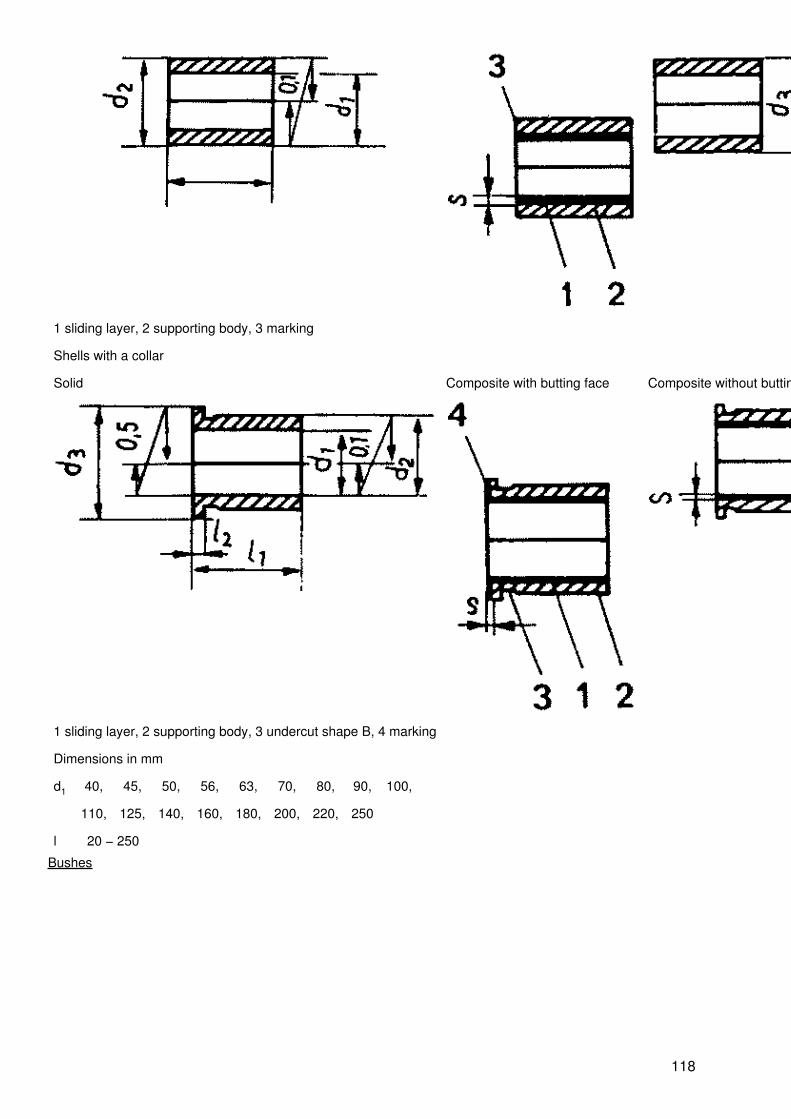
1 sliding layer, 2 supporting body, 3 marking
Shells with a collar
Solid Composite with butting face Composite without butting face
1 sliding layer, 2 supporting body, 3 undercut shape B, 4 marking
Dimensions in mm
d1 40, 45, 50, 56, 63, 70, 80, 90, 100,
110, 125, 140, 160, 180, 200, 220, 250
l 20 − 250
Bushes
118

Bushes without collars
Type Material
Solid steel, grey cast iron, non−ferrous metal sinter metal moulded material
Composite Sliding layer of non−ferrous metal, supporting body of steel
Designation example
Dimensions in mm
d1 4, 8, 10, 14, 16, 18, 20, 22, 25, 28, 32,
36, 40, 45, 50, 55, 63, 70, 80, 90, 100
l 3 − 100
119
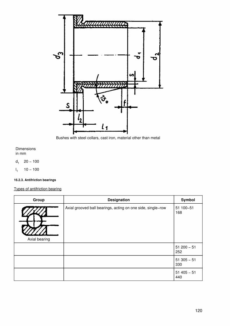
Bushes with steel collars, cast iron, material other than metal
Dimensionsin mm
d1 20 − 100
l1 10 − 100
16.2.3. Antifriction bearings
Types of antifriction bearing
Group Designation Symbol
Axial bearing
Axial grooved ball bearings, acting on one side, single−row 51 100−51168
51 200 − 51252
51 305 − 51330
51 405 − 51440
120

Axial grooved ball bearings, acting on two sides 52 202 − 52220
52 305 − 52314
52 408 − 52420
Radial bearings
Radial grooved ball bearings without loading slots, single−row 60 − 60/500
607 − 609
623 − 626
627, 629
634, 635
6200 − 6244
6300 − 6330
Self−aligning ball bearings, double−row 1200 − 1222
1204k −1222k
1300 − 1318
1340k −1318k
Cylindrical roller bearings with outside restraining flanges Nu 1005 − NU1020
121
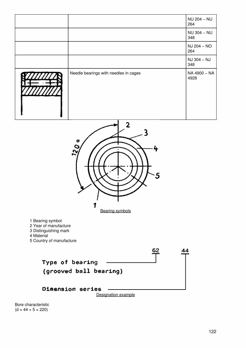
NU 204 − NU264
NU 304 − NU348
NJ 204 − NO264
NJ 304 − NJ348
Needle bearings with needles in cages NA 4900 − NA4928
Bearing symbols
1 Bearing symbol2 Year of manufacture3 Distinguishing mark4 Material5 Country of manufacture
Designation example
Bore characteristic(d = 44 × 5 = 220)
122

Bore diameter in mm Bore characteristic Example
3 − 9 Bore diameter in mm 609
10 00 62 00
12 01 62 01
15 02 62 02
17 03 62 03
20 − 480 1/5 bore diameter 62 44
(d = 44 × 5= 220)
22, 28, 32 Bore diameter in mm
> 480 Separated by diagonal stroke from the symbol of the 60/500 bearingseries
17. Transmission elements
17.1. Shafts
17.1.1. Types of shafts
Classificationaspect
Designation Function Explanation
Longitudinalsection
Straight shafts simple transmission of rotary motions
Crankshafts conversion of rotary motions into straight−line motionsand vice versa
Mobility Rigid shafts, articulated shafts like straight shafts compensation of paralleldisplacement or angular displacement between thecentral axes of two shafts
123
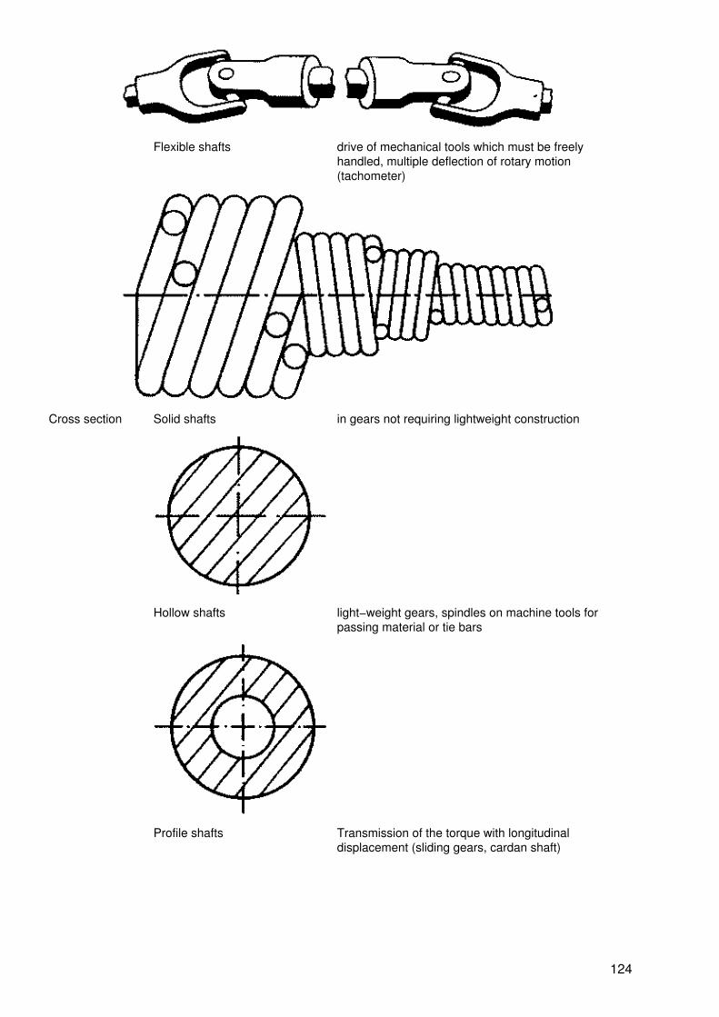
Flexible shafts drive of mechanical tools which must be freelyhandled, multiple deflection of rotary motion(tachometer)
Cross section Solid shafts in gears not requiring lightweight construction
Hollow shafts light−weight gears, spindles on machine tools forpassing material or tie bars
Profile shafts Transmission of the torque with longitudinaldisplacement (sliding gears, cardan shaft)
124

17.1.2. Diameters of shafts (axle diameters)
Preferred dimensions, selection series
Ra5 Ra10 Ra20 R40 Ra5 Ra10 Ra20 R40
10 10 10 10 32 32 32
10.5 34
11 11 36 36
11.5 38
12 12 12 40 40 40 40
13 42
14 14 45 45
15 48
16 16 16 16 50 50 50
17 52
18 18 55 55
19 60
20 20 20 60 60 60 63
21 65
22 22 70 70
24 75
25 25 25 25 80 80 80
26 85
28 28 90 90
30 95
100 100 100 100 200 200 200
105 210
110 110 220 220
120 240
125

125 125 125 250 250 250 250
130 260
140 140 280 280
150 300
160 160 160 160 320 320 320
170 340
180 180 360 360
190 380
17.1.3. Cylindrical shaft ends (axle ends)
Designation according to application offorce
Designation according to shape Explanation
Pivot (radial application of force)
End journal
easy tomanufacture andinstall
Neck collar journal
frequently splitbearing shellsrequired,time−consuminginstallation
Pivot journal (axial application of force)
Solid pivot journal
unfavourable,lubricatingconditions, sincethere is slowsliding speed atthe pivot point
126

Pivot journal
Ring pivot
improvedlubricatingconditions 1 oilduct
Ball journal
changes inangles of axlesand shafts havenot influence onbearingconditions
17.1.4. Shaft packings
Designation Explanation
Felt ring
only suitable for greaselubrication (simple packing); oilpasses unhindered
127

Radial packing
prevents oil leakage; contactforce is increased by springwasher (gear shafts)1 inner ring, 2 spring washer, 3casing, 4 gasket
Radial packing with dust−proof lip
prevents oil leakage andpenetration of dust (crankshafts)1 space to be sealed
Sealing grooves
turned−in grooves relievepressure stepwise to approx. 0(pistons, centrifugal compressors)1 pressure side, 2 pressure drop
oil is centrifuged by centrifugalforce and prevented from leaking
128
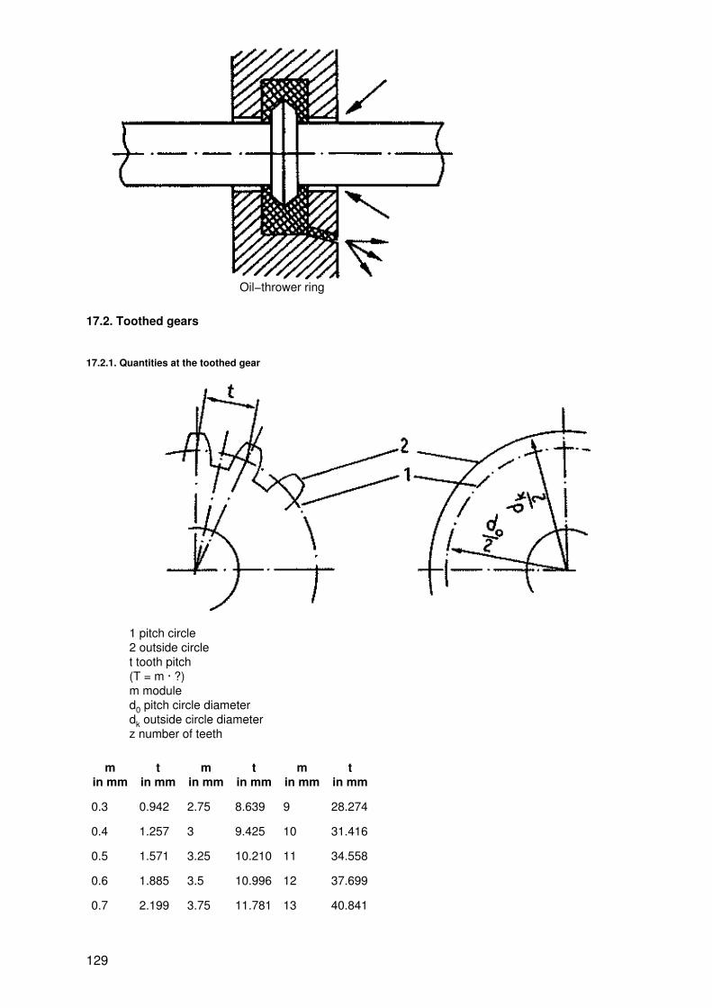
Oil−thrower ring
17.2. Toothed gears
17.2.1. Quantities at the toothed gear
1 pitch circle2 outside circlet tooth pitch(T = m · ?)m moduled0 pitch circle diameterdk outside circle diameterz number of teeth
min mm
tin mm
min mm
tin mm
min mm
tin mm
0.3 0.942 2.75 8.639 9 28.274
0.4 1.257 3 9.425 10 31.416
0.5 1.571 3.25 10.210 11 34.558
0.6 1.885 3.5 10.996 12 37.699
0.7 2.199 3.75 11.781 13 40.841
129

0.8 2.513 4 12.566 14 43.982
0.9 2.827 4.5 14.137 15 47.124
1 3.142 5 15.708 16 50.265
1.25 3.927 5.5 17.279 18 56.449
1.5 4.712 6 18.850 20 62.832
1.75 5.488 6.5 20.420 22 69.115
2 6.283 7 21.991 24 75.398
2.25 7.069 8 25.133 27 84.823
2.5 7.854
17.2.2. Types of toothed wheel gearings
Representation complete simplified symbol
Spur gears on parallel axes− Outside gears
1 spur gears, 2 helical gears− Inside gears
− Spur gear with rack
130
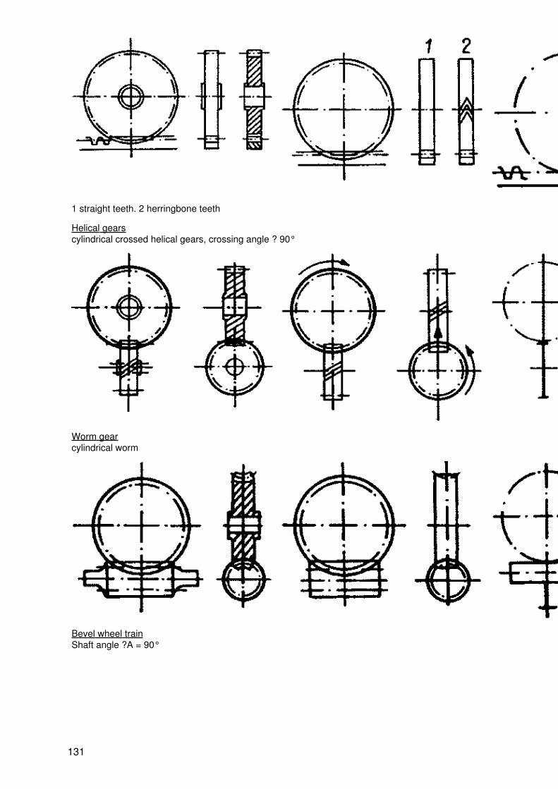
1 straight teeth. 2 herringbone teeth
Helical gearscylindrical crossed helical gears, crossing angle ? 90°
Worm gearcylindrical worm
Bevel wheel trainShaft angle ?A = 90°
131
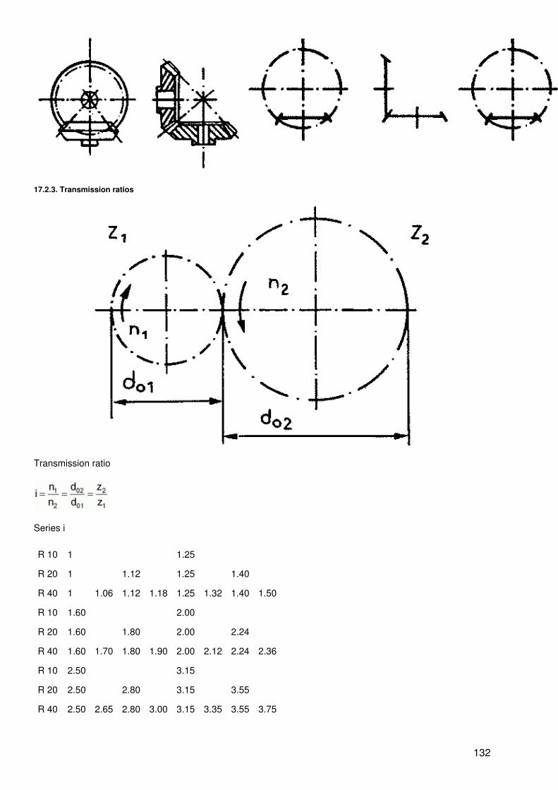
17.2.3. Transmission ratios
Transmission ratio
Series i
R 10 1 1.25
R 20 1 1.12 1.25 1.40
R 40 1 1.06 1.12 1.18 1.25 1.32 1.40 1.50
R 10 1.60 2.00
R 20 1.60 1.80 2.00 2.24
R 40 1.60 1.70 1.80 1.90 2.00 2.12 2.24 2.36
R 10 2.50 3.15
R 20 2.50 2.80 3.15 3.55
R 40 2.50 2.65 2.80 3.00 3.15 3.35 3.55 3.75
132
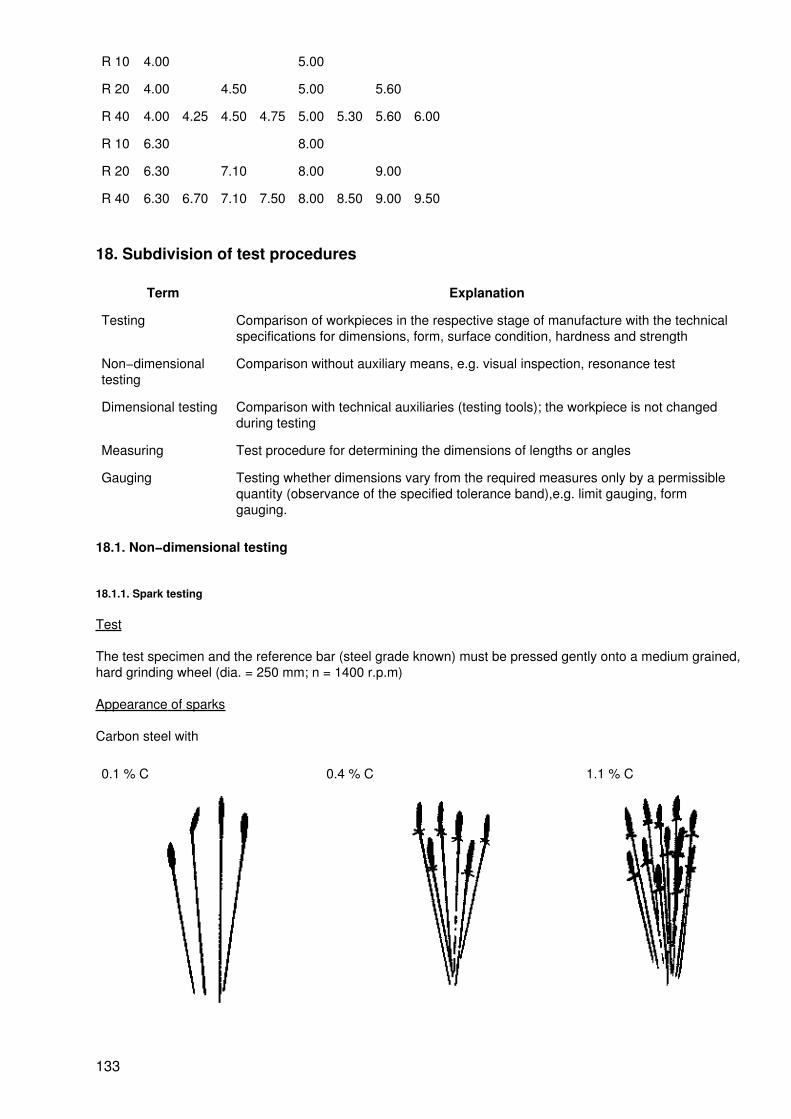
R 10 4.00 5.00
R 20 4.00 4.50 5.00 5.60
R 40 4.00 4.25 4.50 4.75 5.00 5.30 5.60 6.00
R 10 6.30 8.00
R 20 6.30 7.10 8.00 9.00
R 40 6.30 6.70 7.10 7.50 8.00 8.50 9.00 9.50
18. Subdivision of test procedures
Term Explanation
Testing Comparison of workpieces in the respective stage of manufacture with the technicalspecifications for dimensions, form, surface condition, hardness and strength
Non−dimensionaltesting
Comparison without auxiliary means, e.g. visual inspection, resonance test
Dimensional testing Comparison with technical auxiliaries (testing tools); the workpiece is not changedduring testing
Measuring Test procedure for determining the dimensions of lengths or angles
Gauging Testing whether dimensions vary from the required measures only by a permissiblequantity (observance of the specified tolerance band),e.g. limit gauging, formgauging.
18.1. Non−dimensional testing
18.1.1. Spark testing
Test
The test specimen and the reference bar (steel grade known) must be pressed gently onto a medium grained,hard grinding wheel (dia. = 250 mm; n = 1400 r.p.m)
Appearance of sparks
Carbon steel with
0.1 % C 0.4 % C 1.1 % C
133
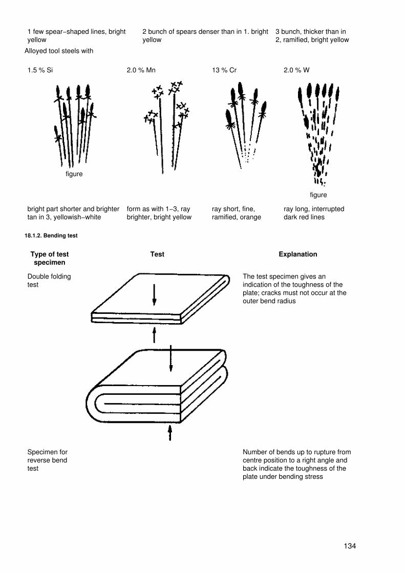
1 few spear−shaped lines, brightyellow
2 bunch of spears denser than in 1. brightyellow
3 bunch, thicker than in2, ramified, bright yellow
Alloyed tool steels with
1.5 % Si 2.0 % Mn 13 % Cr 2.0 % W
figure
figure
bright part shorter and brightertan in 3, yellowish−white
form as with 1−3, raybrighter, bright yellow
ray short, fine,ramified, orange
ray long, interrupteddark red lines
18.1.2. Bending test
Type of testspecimen
Test Explanation
Double foldingtest
The test specimen gives anindication of the toughness of theplate; cracks must not occur at theouter bend radius
Specimen forreverse bendtest
Number of bends up to rupture fromcentre position to a right angle andback indicate the toughness of theplate under bending stress
134
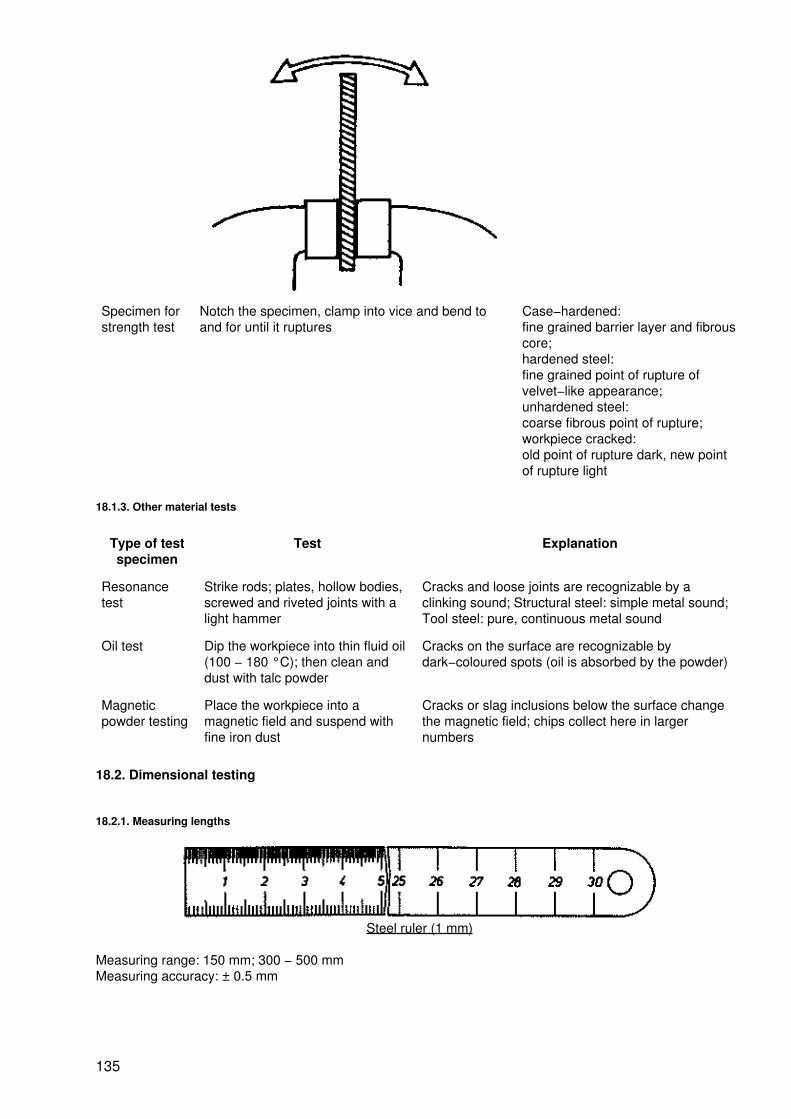
Specimen forstrength test
Notch the specimen, clamp into vice and bend toand for until it ruptures
Case−hardened:fine grained barrier layer and fibrouscore;hardened steel:fine grained point of rupture ofvelvet−like appearance;unhardened steel:coarse fibrous point of rupture;workpiece cracked:old point of rupture dark, new pointof rupture light
18.1.3. Other material tests
Type of testspecimen
Test Explanation
Resonancetest
Strike rods; plates, hollow bodies,screwed and riveted joints with alight hammer
Cracks and loose joints are recognizable by aclinking sound; Structural steel: simple metal sound;Tool steel: pure, continuous metal sound
Oil test Dip the workpiece into thin fluid oil(100 − 180 °C); then clean anddust with talc powder
Cracks on the surface are recognizable bydark−coloured spots (oil is absorbed by the powder)
Magneticpowder testing
Place the workpiece into amagnetic field and suspend withfine iron dust
Cracks or slag inclusions below the surface changethe magnetic field; chips collect here in largernumbers
18.2. Dimensional testing
18.2.1. Measuring lengths
Steel ruler (1 mm)
Measuring range: 150 mm; 300 − 500 mmMeasuring accuracy: ± 0.5 mm
135

Vernier caliper (0.1 mm)
1 fixed arm, 2 movable arm, 3 rule with main division, 4 vernier
Measuring range: 120 mm · 2000 mmMeasuring accuracy: ± 50 ?m
Used for external dimensions internal dimensions depth dimensions
External micrometer (0.01 mm)
136
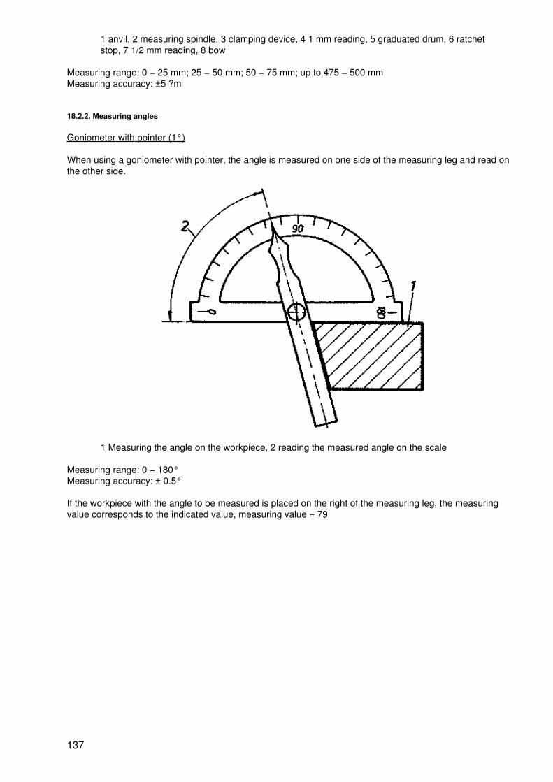
1 anvil, 2 measuring spindle, 3 clamping device, 4 1 mm reading, 5 graduated drum, 6 ratchetstop, 7 1/2 mm reading, 8 bow
Measuring range: 0 − 25 mm; 25 − 50 mm; 50 − 75 mm; up to 475 − 500 mmMeasuring accuracy: ±5 ?m
18.2.2. Measuring angles
Goniometer with pointer (1°)
When using a goniometer with pointer, the angle is measured on one side of the measuring leg and read onthe other side.
1 Measuring the angle on the workpiece, 2 reading the measured angle on the scale
Measuring range: 0 − 180°Measuring accuracy: ± 0.5°
If the workpiece with the angle to be measured is placed on the right of the measuring leg, the measuringvalue corresponds to the indicated value, measuring value = 79
137
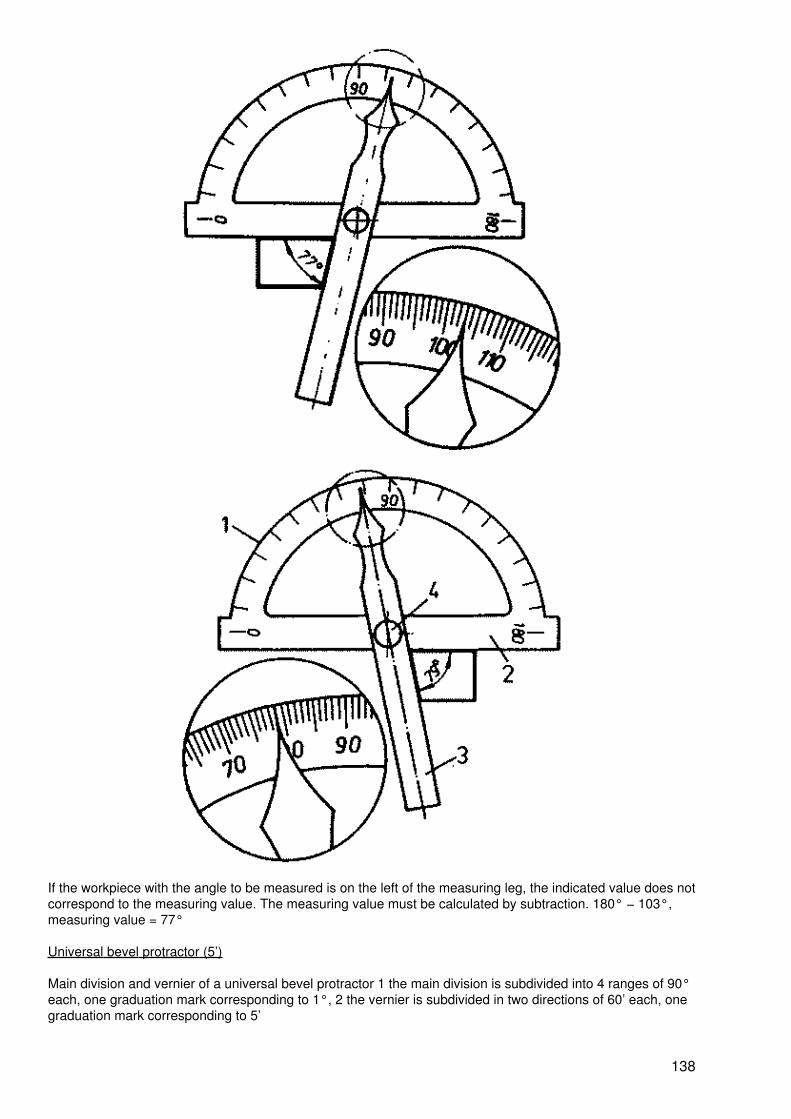
If the workpiece with the angle to be measured is on the left of the measuring leg, the indicated value does notcorrespond to the measuring value. The measuring value must be calculated by subtraction. 180° − 103°,measuring value = 77°
Universal bevel protractor (5’)
Main division and vernier of a universal bevel protractor 1 the main division is subdivided into 4 ranges of 90°each, one graduation mark corresponding to 1°, 2 the vernier is subdivided in two directions of 60’ each, onegraduation mark corresponding to 5’
138

Measuring range: 0 − 180°Measuring accuracy: ±5’
Reading of the measuring value on the universal bevel protractor
a − measuring value 46°35’b − measuring value 3°30’
When reading the measuring value, starting from zero, the full degrees at the zero stroke of the vernier areread on the main division, and the minutes are read in the same direction at the graduation mark of the vernierwhich coincides with a graduation mark on the main division.
139
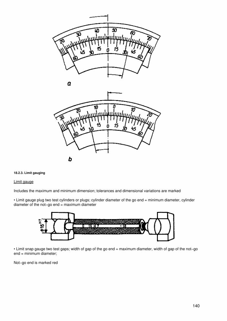
18.2.3. Limit gauging
Limit gauge
Includes the maximum and minimum dimension; tolerances and dimensional variations are marked
• Limit gauge plug two test cylinders or plugs; cylinder diameter of the go end = minimum diameter, cylinderdiameter of the not−go end = maximum diameter
• Limit snap gauge two test gaps; width of gap of the go end = maximum diameter, width of gap of the not−goend = minimum diameter;
Not−go end is marked red
140

• Use of limit gauges
Workpiece dimension between maximum andminimum dimension
Workpiece dimension greater than maximumdimension reworking
Workpiece dimension smaller than minimumdimension rejects
Feeler gauge
Dimensional testing of narrow distances, e.g. when adjusting valves or set screws; in steps of 0.1 mm or 0.05mm
Sheet−iron gauge
The widening at the end of the slot receives the burr of the sheet; steps according to commercial sheetthicknesses
141
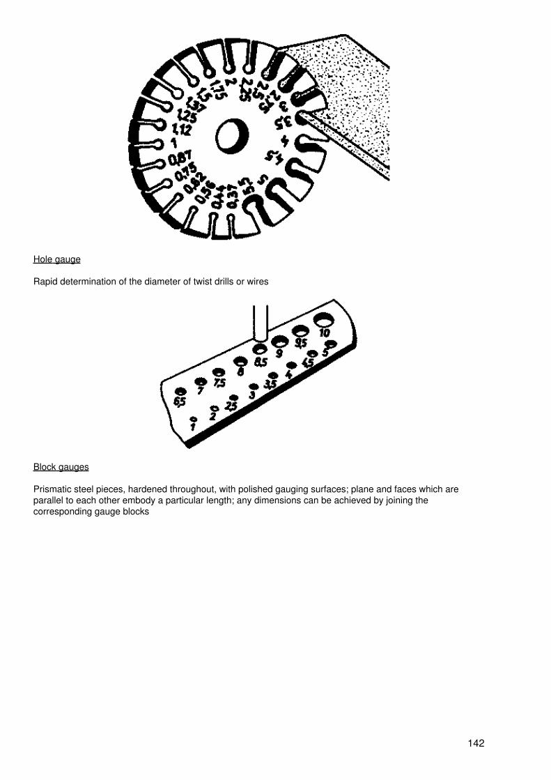
Hole gauge
Rapid determination of the diameter of twist drills or wires
Block gauges
Prismatic steel pieces, hardened throughout, with polished gauging surfaces; plane and faces which areparallel to each other embody a particular length; any dimensions can be achieved by joining thecorresponding gauge blocks
142
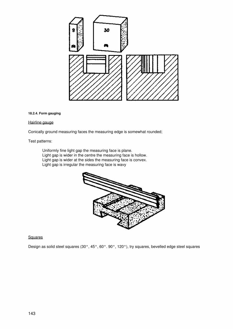
18.2.4. Form gauging
Hairline gauge
Conically ground measuring faces the measuring edge is somewhat rounded;
Test patterns:
Uniformly fine light gap the measuring face is plane.Light gap is wider in the centre the measuring face is hollow.Light gap is wider at the sides the measuring face is convex.Light gap is irregular the measuring face is wavy
Squares
Design as solid steel squares (30°, 45°, 60°. 90°, 120°), try squares, bevelled edge steel squares
143
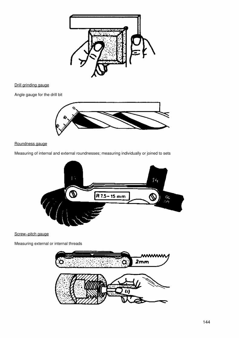
Drill grinding gauge
Angle gauge for the drill bit
Roundness gauge
Measuring of internal and external roundnesses; measuring individually or joined to sets
Screw−pitch gauge
Measuring external or internal threads
144
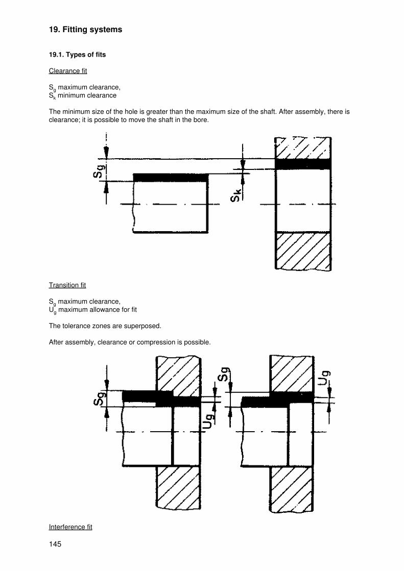
19. Fitting systems
19.1. Types of fits
Clearance fit
Sg maximum clearance,Sk minimum clearance
The minimum size of the hole is greater than the maximum size of the shaft. After assembly, there isclearance; it is possible to move the shaft in the bore.
Transition fit
Sg maximum clearance,Ug maximum allowance for fit
The tolerance zones are superposed.
After assembly, clearance or compression is possible.
Interference fit
145

Ug maximum fit,Ub minimum allowance for fit
The maximum size of the hole is smaller than the minimum size of the shaft.
After assembly there is compression. Shaft and hole are securely connected to each other.
19.2. Systems of fits, basic hole, basic shaft
In the system of fits, 21 tolerance zones are marked by letters of the alphabet. Capital letters are used formarking the hole and small letters for marking the shaft.
Basic hole system
In the basic hole system a standard hole with uniform diameter is used.
Use: General mechanical engineering, tool manufacture
146
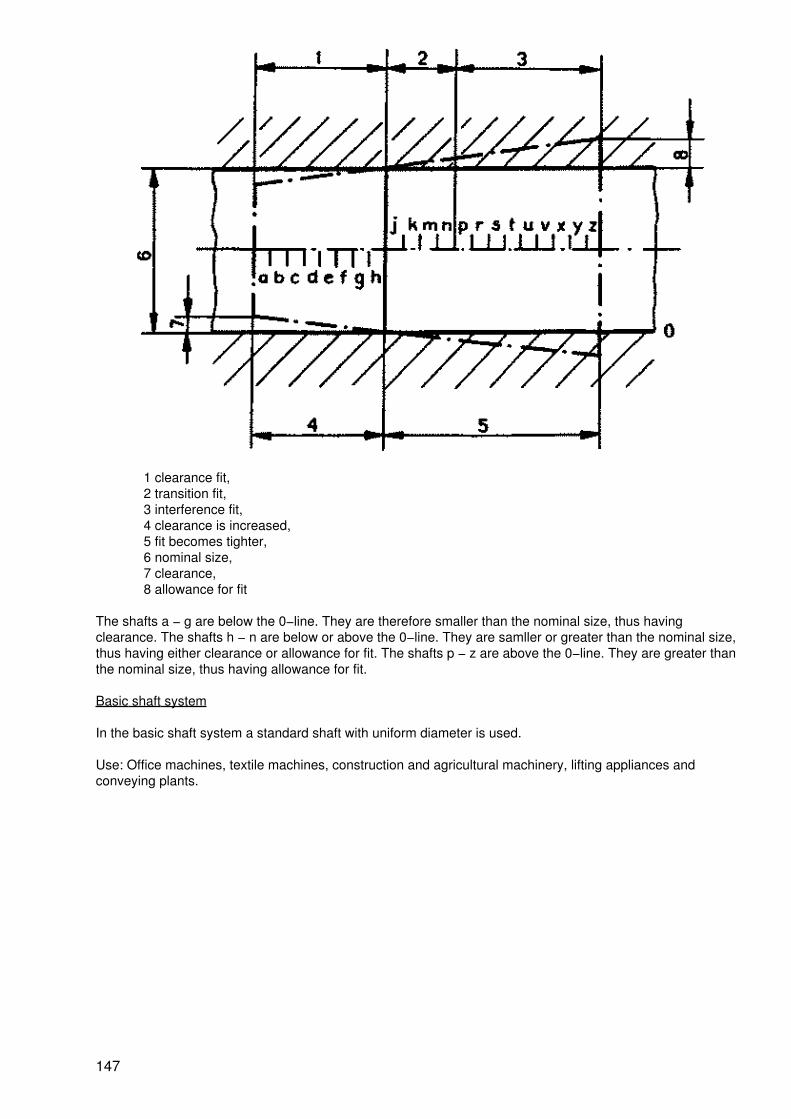
1 clearance fit,2 transition fit,3 interference fit,4 clearance is increased,5 fit becomes tighter,6 nominal size,7 clearance,8 allowance for fit
The shafts a − g are below the 0−line. They are therefore smaller than the nominal size, thus havingclearance. The shafts h − n are below or above the 0−line. They are samller or greater than the nominal size,thus having either clearance or allowance for fit. The shafts p − z are above the 0−line. They are greater thanthe nominal size, thus having allowance for fit.
Basic shaft system
In the basic shaft system a standard shaft with uniform diameter is used.
Use: Office machines, textile machines, construction and agricultural machinery, lifting appliances andconveying plants.
147

1 clearance fits,2 transition fits,3 interference fits,4 clearance is increased,5 fit becomes tighter,6 nominal size,7 clearance,8 allowance for fit
Holes A−G are above the 0−line. They are therefore greater than the nominal size, thus having clearance.The holes H−N are above and below the 0−line. They are greater or smaller than the nominal size, thushaving either clearance or allowance for fit. The holes P − Z are below the 0−line. They are smaller than thenominal size, thus having allowance for fit.
19.3. Examples of fits
Example: dia. 30H11
148

Example: dia. 10r6
Nominal dimensional variations for holes (preferred series)
Range of nominaldimensions mm
D11 F9 F8 H12 H11 H10 H8 H7 J7 J6 K7 K6 N7
Nominal dimensions in ?m
over 1to 3
+ 80+ 20
+ 32+ 7
+ 21+ 7
+ 90+ 0
+ 600
+ 400
+140
+ 90
+ 3− 6
+ 3− 4
−−
−−
− 4−
13
over 3to 6
+105
+ 30
+ 40+ 10
+ 28+ 10
+120
0
+ 750
+ 480
+180
+120
+ 5− 7
+ 4− 4
−−
−−
− 4−
16
over 6to 10
+130
+ 40
+ 49+ 13
+ 35+ 13
+150
0
+ 900
+ 580
+220
+150
+ 8− 7
+ 5− 4
+ 5−
10
+ 2− 7
− 4−
19
over 10to 14
+160
+ 50
+ 59+ 16
+ 43+ 16
+180
0
+110
0
+ 700
+270
+180
+10
− 8
+ 6− 5
+ 6−
12
+ 2− 9
− 5−
23
over 14to 18
over 18to 24
+195
+ 65
+ 72+ 20
+ 53+ 20
+210
0
+130
0
+ 840
+330
+210
+12
− 9
+ 8− 5
+ 6−
15
+ 2−
11
− 7−
28
over 24to 30
over 30to 40
+240
+ 80
+ 87+ 25
+ 64+ 25
+250
0
+160
0
+100
0
+390
+250
+14+
11
+ 10− 6
+ 7−
18
+ 3−
13
− 0−
33
over 40to 50
over 50to 65
+290
+100
+104
+ 30
+ 76+ 30
+300+ 0
+190
0
+120
0
+460
+300
+18−
12
+ 13− 6
+ 9−
21
+ 4−
15
− 9−
39
over 65to 80
over 80to 100
+340
+120
+123
+ 36
+ 90+ 36
+350
0
+220
0
+140
0
+540
+350
+22−
13
+ 166
+10−
25
+ 4−
18
−10−
45
over 100to 120
149

over 120to 140
over 140to 160
+395
+145
+143
+ 43
+106
+ 43
+400
0
+250
0
+160
0
+630
+400
+26−
14
+ 187
+12−
28
+ 4−
21
−12−
52
over 160to 180
over 180to 200
over 200to 225
+460
+170
+165
+ 50
+122
+ 50
+460
0
+290
0
+185
0
+720
+460
+30−
16
+ 22− 7
+13−
33
+ 5−
24
−14−
60
over 225to 250
over 250to 280 +
510+
186+
137+
520+
320+
210+
81+
52+
36+ 25 +
16+ 5 −
14
over 280to 315
+190
+ 56 + 56 0 0 0 0 0 −16
7 −36
−27
−66
over 315to 355 +
570+
202+
151+
570+
360+
230+
89+
57+
39+ 29 +
17+ 7 −
18
over 355to 400
+210
+ 62 + 62 0 0 0 0 0 −18
7 −40
−29
−73
over 400to 450 +
630+
223+
165+
630+
400+
250+
97+
63+
43+ 33 +
18+ 8 −
17
over 450to 500
+230
+ 68 + 68 0 0 0 0 0 −20
− 7 −45
−32
−80
Nominal dimensionsal variations for shafts (some preferred series)
Range of nominaldimensions mm
D11 D9 E8 F9 F7 H12 H11 H8 H7 H6 J6 K6 N6
Nominal dimensions in mm
over 1to 3
− 20− 80
− 20− 45
− 14− 28
7− 32
− 7− 16
0− 90
0− 60
0−
14
0− 9
0− 7
+ 6− 1
−−
+13
+ 6
over 3to 6
− 30−
105
− 30− 60
− 20− 38
− 10− 40
− 10− 22
0−
120
0− 75
0−
18
0−
12
0− 8
+ 7− 1
−−
+16
+ 8
over 6to 10
− 40−
130
− 40− 76
− 25− 47
− 13− 49
− 13− 28
0−
150
0− 90
0−
22
0−
15
0− 9
+ 7− 2
+10
+ 1
+19+
10
over 10to 14
− 50−
160
− 50− 93
− 32− 59
− 16− 59
− 16− 34
0−
180
0−
110
0−
27
0−
18
0−
11
+ 8− 3
+12
+ 1
+23+
150

12
over 14to 18
over 18to 24
− 65−
195
− 65−
117
− 40− 73
− 20− 72
− 20− 41
0−
210
0−
130
0−
33
0−
21
0−
13
+ 9− 4
+15
+ 2
+28+
15
over 24to 30
over 30to 40
− 80−
240
− 80−
142
− 50− 89
− 25− 87
− 25− 50
0−
250
0−
160
0−
39
0−
25
0−
16
+11
− 5
+18
+ 2
+33+
17
over 40to 50
over 50to 65
−100
−290
−100
−174
− 60−
106
− 30−
104
− 30− 60
0−
300
0−
190
0−
46
0−
30
0−
19
+12
− 7
+21
+ 2
+39+
20
over 65to 80
over 80to 100
−120
−340
−120
−207
− 72−
123
− 36−
123
− 36− 71
0−
350
0−
220
0−
54
0−
35
0−
22
+13
− 9
+25
+ 3
+45+
23
over 100to 120
over 120to 140
−145
−395
−145
−245
− 85−
148
− 43−
143
− 43− 83
0−
400
0−
250
0−
63
0−
40
0−
25
+14−
11
+28
+ 3
+52+
27
over 140to 160
over 160to 180
over 180to 200
−170
−460
−170
−285
−100
−172
− 50−
165
− 50− 96
0−
460
0−
290
0−
72
0−
46
0−
29
+16−
13
+33
+ 4
+60+
31
over 200to 225
over 225to 250
over 250to 280
−190
−510
−190
−320
−110
−191
− 56−
186
− 56−
108
0−
520
0−
320
0−
81
0−
52
0−
32
+16−
16
+36
+ 4
+66+
34
over 280to 315
151

over 315to 355
−210
−570
−210
−350
−125
−214
− 62−
202
− 62−
119
0−
570
0−
360
0−
89
0−
57
0−
36
+18−
18
+40
+ 4
+73+
37
over 355to 400
over 400to 450
−230
−630
−230
−385
−135
−232
− 68−
223
− 68−
131
0−
630
0−
400
0−
97
0−
63
0−
40
+20−
20
+45
+ 5
+80+
40
over 450to 500
20. Scribing
20.1. Types of scribing
Scribing according to reference edge
The reference edge is a well−prepared edge of the workpiece to which all dimensions are referred.
Scribing according to the reference line
152
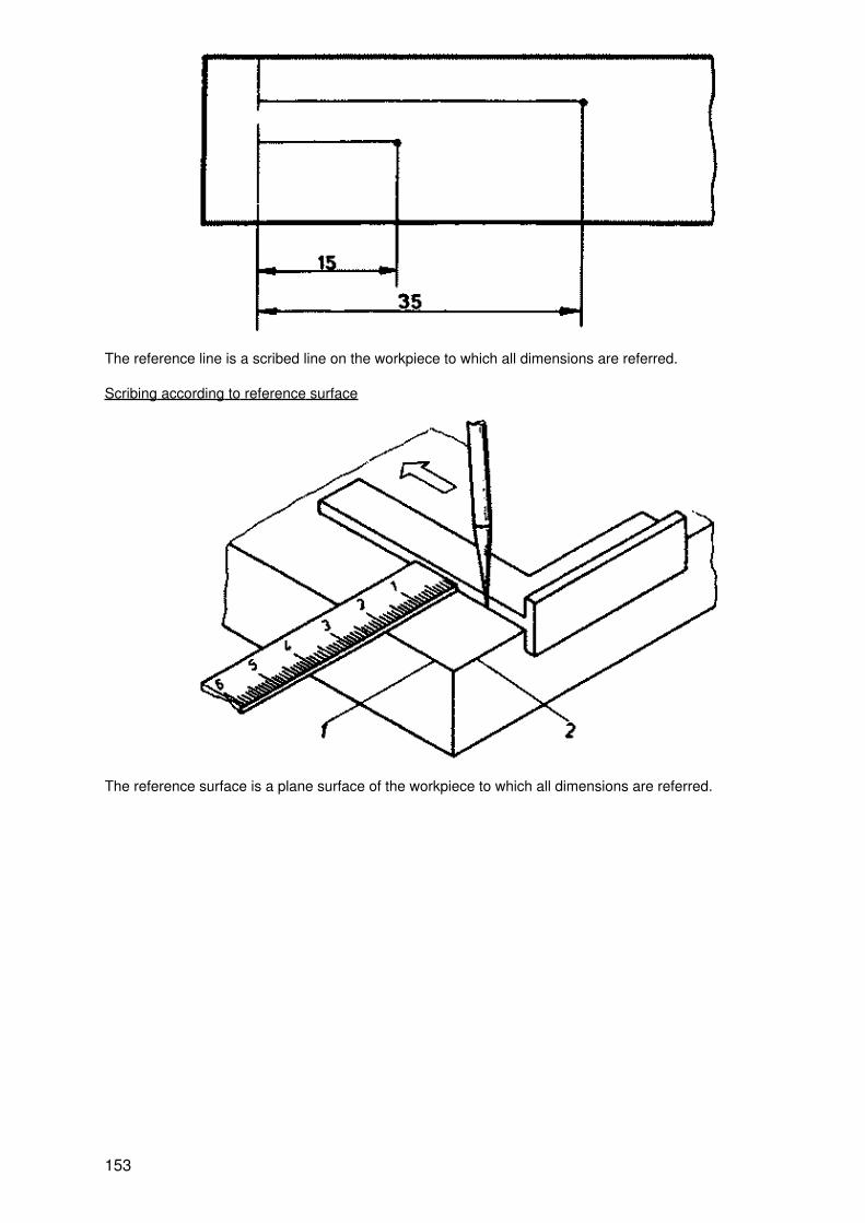
The reference line is a scribed line on the workpiece to which all dimensions are referred.
Scribing according to reference surface
The reference surface is a plane surface of the workpiece to which all dimensions are referred.
153
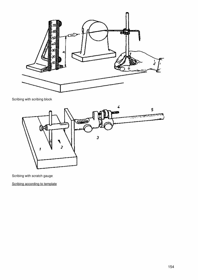
Scribing with scribing block
Scribing with scratch gauge
Scribing according to template
154
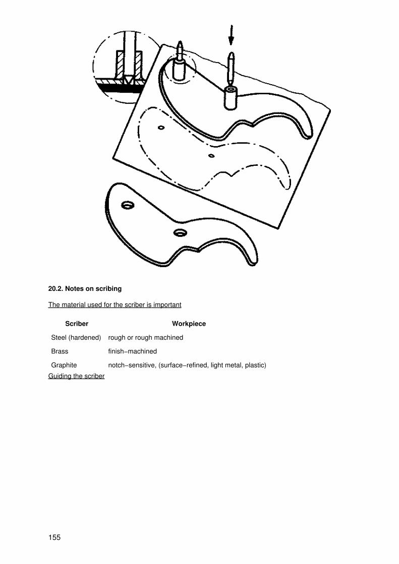
20.2. Notes on scribing
The material used for the scriber is important
Scriber Workpiece
Steel (hardened) rough or rough machined
Brass finish−machined
Graphite notch−sensitive, (surface−refined, light metal, plastic)
Guiding the scriber
155

Making punch marks
Set the centre punch exactly on the scribed line straight scribed line − large distance between the punchmarks curbed scribed line − short distance between the punch marks
Scribing of spacings with the compass
156
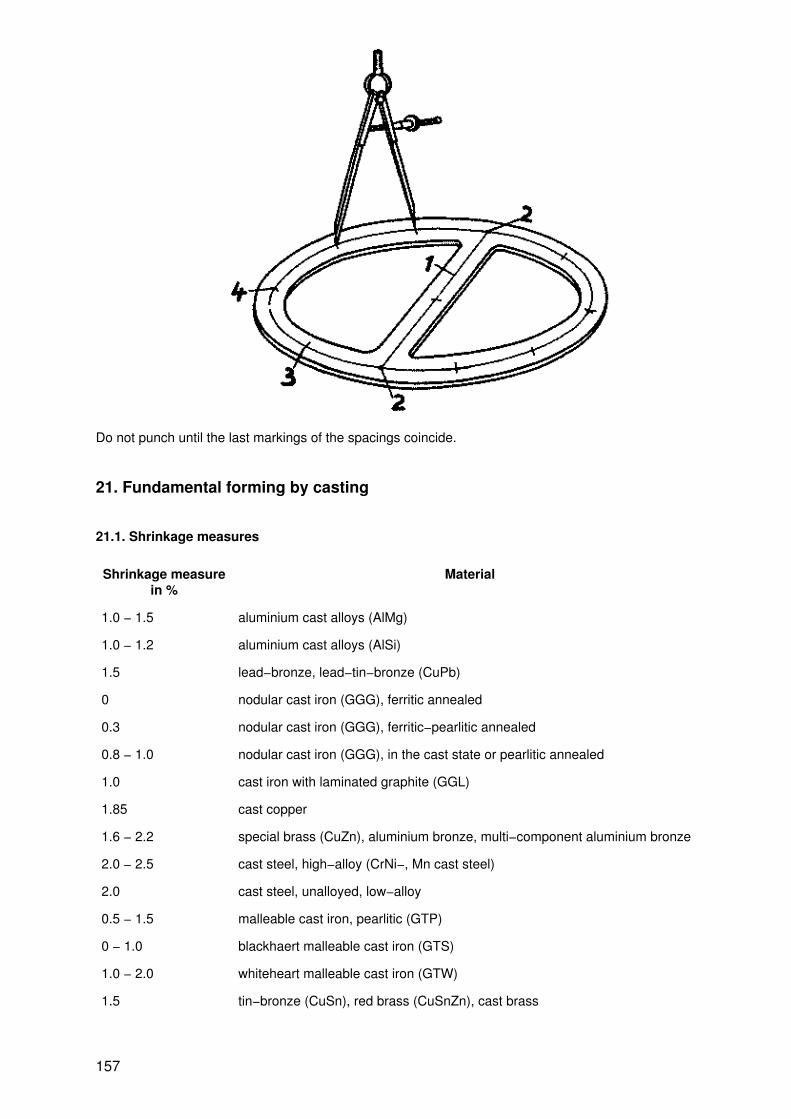
Do not punch until the last markings of the spacings coincide.
21. Fundamental forming by casting
21.1. Shrinkage measures
Shrinkage measurein %
Material
1.0 − 1.5 aluminium cast alloys (AlMg)
1.0 − 1.2 aluminium cast alloys (AlSi)
1.5 lead−bronze, lead−tin−bronze (CuPb)
0 nodular cast iron (GGG), ferritic annealed
0.3 nodular cast iron (GGG), ferritic−pearlitic annealed
0.8 − 1.0 nodular cast iron (GGG), in the cast state or pearlitic annealed
1.0 cast iron with laminated graphite (GGL)
1.85 cast copper
1.6 − 2.2 special brass (CuZn), aluminium bronze, multi−component aluminium bronze
2.0 − 2.5 cast steel, high−alloy (CrNi−, Mn cast steel)
2.0 cast steel, unalloyed, low−alloy
0.5 − 1.5 malleable cast iron, pearlitic (GTP)
0 − 1.0 blackhaert malleable cast iron (GTS)
1.0 − 2.0 whiteheart malleable cast iron (GTW)
1.5 tin−bronze (CuSn), red brass (CuSnZn), cast brass
157

21.2. Machining allowances for castings
21.2.1. Cast steel, allowances for external surfaces
Nominalsize
in mm
Allowances per surface in mm
Maximumsize of thecasting (1,b, h or dia.)
hand moulded machine moulded
over to bottom side top bottom side top
− 160 4 4 6 3 4 6
160 250 5 5 7 4 4 7
250 400 6 6 8 5 5 8
400 630 7 7 9 6 6 9
630 1000 8 8 10 7 7 10
21.2.2. Cast steel, allowances for holes and openings
Nominalsizesin mm
Allowances per surface in mm
Lengths of the holes andopenings in mm
Max. insidediameter or
max. internaldimension
over
− 250 400 630 1000 1600
to
250 400 630 1000 1600 2000
over to
80 160 7 9 − − − −
160 250 8 10 12 14 16 −
250 400 9 11 13 15 17 19
400 630 10 12 14 16 18 20
630 1000 11 13 15 17 19 21
21.2.3. Grey cast iron and malleable cast iron, allowances
Nominalsizesin mm
Allowances per surface in mm
hand moulded machinemoulded
158
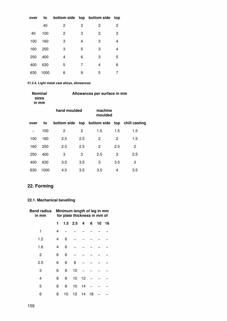
over to bottom side top bottom side top
40 2 3 2 2
40 100 2 3 2 3
100 160 3 4 3 4
160 250 3 5 3 4
250 400 4 6 3 5
400 630 5 7 4 6
630 1000 6 9 5 7
21.2.4. Light metal cast alloys, allowances
Nominalsizesin mm
Allowances per surface in mm
hand moulded machinemoulded
over to bottom side top bottom side top chill casting
− 100 2 2 1.5 1.5 1.5
100 160 2.5 2.5 2 2 1.5
160 250 2.5 2.5 2 2.5 2
250 400 3 3 2.5 3 2.5
400 630 3.5 3.5 3 3.5 3
630 1000 4.5 3.5 3.5 4 3.5
22. Forming
22.1. Mechanical bevelling
Bend radiusin mm
Minimum length of leg in mmfor plate thickness in mm of
1 1.5 2.5 4 6 10 16
1 4 − − − − − −
1.2 4 6 − − − − −
1.6 4 6 − − − − −
2 6 6 − − − − −
2.5 6 6 8 − − − −
3 6 8 10 − − − −
4 8 8 10 12 − − −
5 8 8 10 14 − − −
6 8 10 12 14 18 − −
159

8 10 12 14 16 22 − −
10 12 14 16 18 22 32 −
20 22 25 25 28 32 40 60
40 − − 45 50 55 60 80
50 − − − 60 60 80 90
22.2. Bending
22.2.1. Bend radii
Bend radius r in mm
1.0; 1.2; 1.6; 2.0; 2.5; 3.0; 4.0;
5.0; 6.0; 8.0; 10.0; 12.0; 16.0; 20.0;
25.0; 28.0; 32.0; 36.0; 40.0; 45.0; 50.0;
63.0; 80.0; 100.0; 110.0; 125.0; 140.0; 160.0;
180.0; 200.0;
In the roundness, the thickness is reduced by about 20 %.
22.2.2. Radius of the neutral layer
Figure Calculation
1. r > 5sneutral layer is in the centre of theworkpiece
1 neutral layerR radius of the neutral layerr bend radiuss thickness of the workpiece
2. r < 5sneutral layer is shifted to the inside of thebending point
22.2.3. Extended length
Figure Calculation (rule of thumb)
160
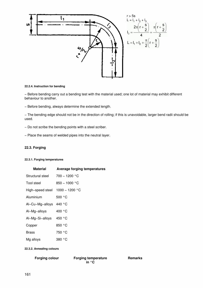
r > 5sL = l1 + l2 + l3
22.2.4. Instruction for bending
− Before bending carry out a bending test with the material used; one lot of material may exhibit differentbehaviour to another.
− Before bending, always determine the extended length.
− The bending edge should not be in the direction of rolling; if this is unavoidable, larger bend radii should beused.
− Do not scribe the bending points with a steel scriber.
− Place the seams of welded pipes into the neutral layer.
22.3. Forging
22.3.1. Forging temperatures
Material Average forging temperatures
Structural steel 700 − 1200 °C
Tool steel 850 − 1000 °C
High−speed steel 1000 − 1200 °C
Aluminium 500 °C
Al−Cu−Mg−alloys 440 °C
Al−Mg−alloys 400 °C
Al−Mg−Si−alloys 450 °C
Copper 850 °C
Brass 750 °C
Mg alloys 380 °C
22.3.2. Annealing colours
Forging colour Forging temperaturein °C
Remarks
161
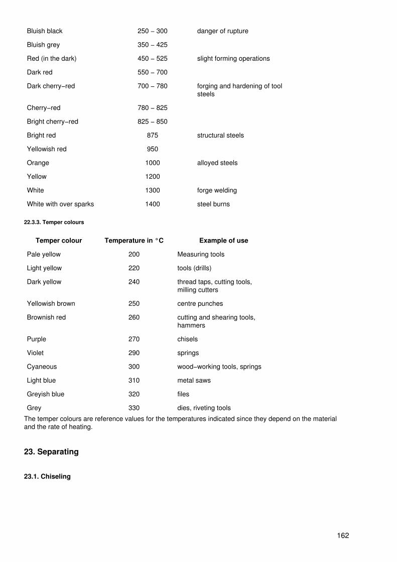
Bluish black 250 − 300 danger of rupture
Bluish grey 350 − 425
Red (in the dark) 450 − 525 slight forming operations
Dark red 550 − 700
Dark cherry−red 700 − 780 forging and hardening of toolsteels
Cherry−red 780 − 825
Bright cherry−red 825 − 850
Bright red 875 structural steels
Yellowish red 950
Orange 1000 alloyed steels
Yellow 1200
White 1300 forge welding
White with over sparks 1400 steel burns
22.3.3. Temper colours
Temper colour Temperature in °C Example of use
Pale yellow 200 Measuring tools
Light yellow 220 tools (drills)
Dark yellow 240 thread taps, cutting tools,milling cutters
Yellowish brown 250 centre punches
Brownish red 260 cutting and shearing tools,hammers
Purple 270 chisels
Violet 290 springs
Cyaneous 300 wood−working tools, springs
Light blue 310 metal saws
Greyish blue 320 files
Grey 330 dies, riveting tools
The temper colours are reference values for the temperatures indicated since they depend on the materialand the rate of heating.
23. Separating
23.1. Chiseling
162

23.1.1. Design and types of chisels
1 cutting edge2 head3 shank? = 30 − 70°
Chisels are made of unalloyed tool steel with a carbon content of 0.9 %; cutting edge forged, hardened,ground and tempered; Weight of hammer: weight of chisel = 2: 1
Types of chisels
Flat chisel Cross−cut chisel Gouge Slotting bit Separating chisel
23.1.2. Working techniques for chiseling
Separating with the chisel
163

Chiseling off a sheet strip
Cutting out a bend
Cutting out a corner roundness
164

Cutting out straps
Cutting with the chisel
Chiseling a groove
Chiseling a surface
165

23.2. Shearing
23.2.1. Types and use of shears
Types of shears Use
Hand plate shears
for short cuts;suitable workpiecethicknesses:steel 0.5 − 1;brass 0.8;copper 1.2 − 2.5;zinc 1.6;
1 shear blade2 limit of lift
Punching shears
for curved cuts;for thickness ofworkpiece,see above
Through shears
for long straight cuts;for thickness ofworkpiece, see above
Plate shears
for plates, panels, bends
1 upper shear blade2 lower shear blade
166

Hand lever shears
for steel plate up toabout 6 mm thick;cutting−wedge angle? = 75 − 85°;cutting gap angle:b = 0.05 s for softmaterialsb = 0.1 s for hardmaterials
1 hand lever,2 lever locking device,3 frame, 4 hold−down,5 shear blade
23.2.2. Shearing strength of materials
Material Shearing strength in MPa
Aluminium
soft 70 − 90
hard 130 − 160
Lead 20 − 30
Bronze
soft 220 − 400
hard 400 − 600
Artificialresin
25 − 30
Copper
soft 180 − 220
hard 250 − 300
Brass
soft 220 − 300
hard 350 − 400
Zinc 120 − 200
167

Tin 30 − 40
23.3. Sawing
23.3.1. Hand sawing
Design of the hand hacksaw
1 handle,2 clamp dog.3 saw frame,4 wing nut for clamping? clearance angle? cutting−wedge angle? rake angle
Saw pitches for hand saw blades
Designation Number ofteeth on a
length of 25mm
Shape Use
Coarse 14 − 16 Soft steel, aluminium,copper, plastic, mouldedmaterial
Medium 22 Medium hard steel, hardlight metals, brass;sectional steel, sections,thick−walled pipes
Fine 32 Hard materials,Thin−walled pipes, weaksections
Instructions for sawing
− Clamp the saw blade so that the teeth point in the direction of sawing.
168

− Assist the start of sawing by notching the rear edge of the workpiece with a triangular file.
− Select the correct number of strokes (50 − 60 double strokes per minute)
− Utilize the full length of the saw blades.
− Relieve the saw of load in the return stroke.
− Do not saw pipes straight through; turn them during sawing.
23.3.2. Mechanical sawing
Cutting speed when using a curcular saw
Material Strength in MPa ?B Cutting speed in m/min
Structural steel 340 − 420 26 − 28
over 420 − 550 24 − 26
over 500 − 600 22 − 24
over 600 − 700 18 − 20
over 700 − 850 14 − 16
Alloyed steel 750 − 800 14 − 16
over 800 − 850 12 − 15
over 900 − 950 10 − 14
over 950 − 1050 9 − 12
over 1050 −1200 8 − 10
Cast steel 400 − 500 18 − 20
over 500 − 600 14 − 16
over 600 8 − 10
Aluminium 300 − 500
Bronze 80 − 120
Grey cast iron 150 − 220 14 − 18
over 220 − 300 12 − 15
Copper 100 − 200
Zinc 150 − 300
Brass
Cutting speed when using a band saw
Material Strength in MPa ?B Cutting speed in m/min
Copper 100 − 200
Brass light metal 400 − 1200
Steel over 600 30 − 40
600 − 800 20 − 30
169

800 − 1200 15 − 20
over 1200 10 − 15
Laminated plastic 300 − 900
23.4. Filing
23.4.1. Design of files
1 handle2 tang3 nominal length4 workpiece5 chip space6 chips
Files are made of carbon steel (0.9 − 1.5 % C) or alloyed steel (Mn, Si, Cu); cutting wedges are cut or milled.
23.4.2. Designation of files
Cut no. Designation Number of cutson a file lengthof 10 mm at a
nominal lengthin mm of
100 200 375
0 rough file 10 7.1 5
1 bastard file 14 10 7.1
2 rough−finishing file 22.4 16 11.2
3 smooth−cut file 31.5 22.4 16
170

4 fine smooth−cut file 45 31.5 −
5 finest smooth−cut file 63 45 −
23.4.3. File cross−sections
Cross−section Designation Cut no. Nominal length in mm
knife−edge file 2 − 5 100 − 250
round file 0 − 5 100 − 450
half−round file 0 − 5 100 − 450
cant file 1 − 5 80 − 200
crossing file 1 − 5 80 − 200
flat file 0 − 5 100 − 450
square file 1 − 5 100 − 450
triangular file 1 − 5 100 − 450
23.4.4. Instructions for filing
− Carefully lay the files next to each other, as otherwise the hardened teeth can break out.
− Clamp the workpiece as short as possible.
− Do not file hardened workpieces.
− Degrease the workpieces for filing.
− Check that the file handle fits tightly on the tang
− Clean greased files with a brass plate at right angles to the direction of cut
− Hold the file correctly
23.5. Flame cutting
23.5.1. Cuttable materials
Material cuttable up to(alloying elements)
Preheating temperature
Chrome steel 1.5 % Cr cold cuttable
Carbon steel ? 2 % C
171

Manganese steel 13 % Mn + 1.3 % C
Nickel steel 34 % Ni + 0.5 % Cu
Silicon steel 4 % Si + 0.2 % C
Coppered steel 0.7 % Cu
Titanium −
Titanium alloys −
Tungsten steel 10 % W + 55 % Cr + 0.2 % Ni + 0.8 % C
Chrome steel 1.5 − 10 % Cr hot cuttable
Carbon steel 2 − 2.5 % C above 200 °C
Tungsten steel 10 − 17 % W
23.5.2. Reference values for oxyacetylene cutting
Plate thicknessin mm
Cutting speedin mm/min
Nozzle elevationin mm
Nozzle sizes in mm
Cutting nozzle Heating nozzle
3 − 10 600 − 360 2 − 3 3 − 10 3 − 25
15 − 25 380 − 240 2 − 4 10 − 25
30 − 50 280 − 170 3 − 5 25 − 50 25 − 80
60 − 80 20 − 140 3 − 5 50 − 80
100 − 120 165 − 125 4 − 6 80 − 120 80 − 180
140 − 180 145 − 115 4 − 8 120 − 180
200 − 240 130 − 108 6 − 10 180 − 240 180 − 300
300 100 − 115 8 − 12 240 − 300
Plate thickness inmm
Oxygen pressurein MPa
consumption inl/m
Acetyleneconsumption in l/m
Hydrogenconsumption
in l/m
3 − 10 0.15 36 − 79 3.5 − 10 17 − 48
15 − 25 0.25 92 − 208 15 − 31 61 − 125
30 − 50 0.35 208 − 530 30 − 64 119 − 255
60 − 80 0.5 525 − 975 59 − 96 236 − 386
100 − 120 0.65 1310 − 1630 89 − 126 353 − 507
140 − 180 0.75 1640 − 2640 115 − 156 460 − 626
200 − 240 0.85 2590 − 3700 144 − 183 575 − 732
300 0.9 − 1.0 5000 − 4350 212 − 184 850 − 735
23.6. Drilling
172

23.6.1. Types of drills
Type of drill (selection) Use
Twist drills suitable for most holes; special drills for specific work include deep−hole twistdrills or pin hole drills
Multi−cut stepped drills mainly for countersinking; drilling and countersinking are carried out in oneoperation
Single−lip drills (simpleD−bit)
for deep boring (there must already be low depth bores)
Centre drills for centering workpieces (the tool is a drill and countersink at the same time)
23.6.2. Design of twist drills
Design
1 shank, 2 margin, 3 helical groove, 4 main cutting edge, 5 chisel edge, d = 0.3 − 100 mm
Designation of angles
173

? clearance angle,? cutting−wedge angle,? rake angle,? complementary angle of the chisel edge angle,? point angle
23.6.3. Point angles of twist drills
Workpiece material Point angle in°
Workpiece material Point angle in°
Hard rubber 40 Electron 130
Marble, slate 60 Copper, lead, brass 140
Compression moulding material, thermosettingplastic
90 Al alloy strong, toughsteel
150
Steel, cast steel 118 thin sheets 160
23.6.4. Speed and feed for drilling
Material Drill diameter in mm (high−speed steel)
1 3 5 8 10 12,5 15 20 25 30 40 50
Speed in 1/min
Feed in mm/revolution
174
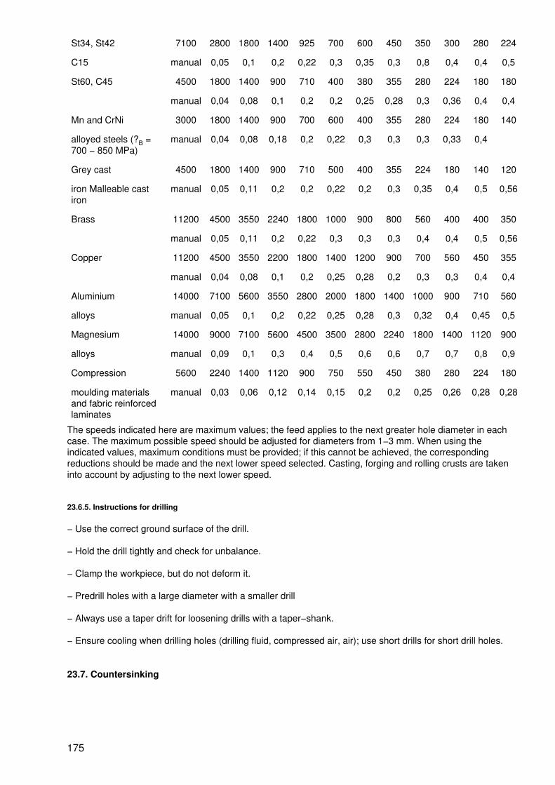
St34, St42 7100 2800 1800 1400 925 700 600 450 350 300 280 224
C15 manual 0,05 0,1 0,2 0,22 0,3 0,35 0,3 0,8 0,4 0,4 0,5
St60, C45 4500 1800 1400 900 710 400 380 355 280 224 180 180
manual 0,04 0,08 0,1 0,2 0,2 0,25 0,28 0,3 0,36 0,4 0,4
Mn and CrNi 3000 1800 1400 900 700 600 400 355 280 224 180 140
alloyed steels (?B =700 − 850 MPa)
manual 0,04 0,08 0,18 0,2 0,22 0,3 0,3 0,3 0,33 0,4
Grey cast 4500 1800 1400 900 710 500 400 355 224 180 140 120
iron Malleable castiron
manual 0,05 0,11 0,2 0,2 0,22 0,2 0,3 0,35 0,4 0,5 0,56
Brass 11200 4500 3550 2240 1800 1000 900 800 560 400 400 350
manual 0,05 0,11 0,2 0,22 0,3 0,3 0,3 0,4 0,4 0,5 0,56
Copper 11200 4500 3550 2200 1800 1400 1200 900 700 560 450 355
manual 0,04 0,08 0,1 0,2 0,25 0,28 0,2 0,3 0,3 0,4 0,4
Aluminium 14000 7100 5600 3550 2800 2000 1800 1400 1000 900 710 560
alloys manual 0,05 0,1 0,2 0,22 0,25 0,28 0,3 0,32 0,4 0,45 0,5
Magnesium 14000 9000 7100 5600 4500 3500 2800 2240 1800 1400 1120 900
alloys manual 0,09 0,1 0,3 0,4 0,5 0,6 0,6 0,7 0,7 0,8 0,9
Compression 5600 2240 1400 1120 900 750 550 450 380 280 224 180
moulding materialsand fabric reinforcedlaminates
manual 0,03 0,06 0,12 0,14 0,15 0,2 0,2 0,25 0,26 0,28 0,28
The speeds indicated here are maximum values; the feed applies to the next greater hole diameter in eachcase. The maximum possible speed should be adjusted for diameters from 1−3 mm. When using theindicated values, maximum conditions must be provided; if this cannot be achieved, the correspondingreductions should be made and the next lower speed selected. Casting, forging and rolling crusts are takeninto account by adjusting to the next lower speed.
23.6.5. Instructions for drilling
− Use the correct ground surface of the drill.
− Hold the drill tightly and check for unbalance.
− Clamp the workpiece, but do not deform it.
− Predrill holes with a large diameter with a smaller drill
− Always use a taper drift for loosening drills with a taper−shank.
− Ensure cooling when drilling holes (drilling fluid, compressed air, air); use short drills for short drill holes.
23.7. Countersinking
175

23.7.1. Types of countersinks
Countersink
Flat countersink
Spiral countersink
176

Head countersink
Form countersink
Combined drill and countersink
Figure Figure Figure Figure Figure
23.7.2. Instructions for countersinking
− Clamp the workpiece and tool tightly.
− Lubricate the pilot pin of the head countersinks and the countersinking tool with pilot.
− If chatter marks occur, adjust to the next lower speed.
177
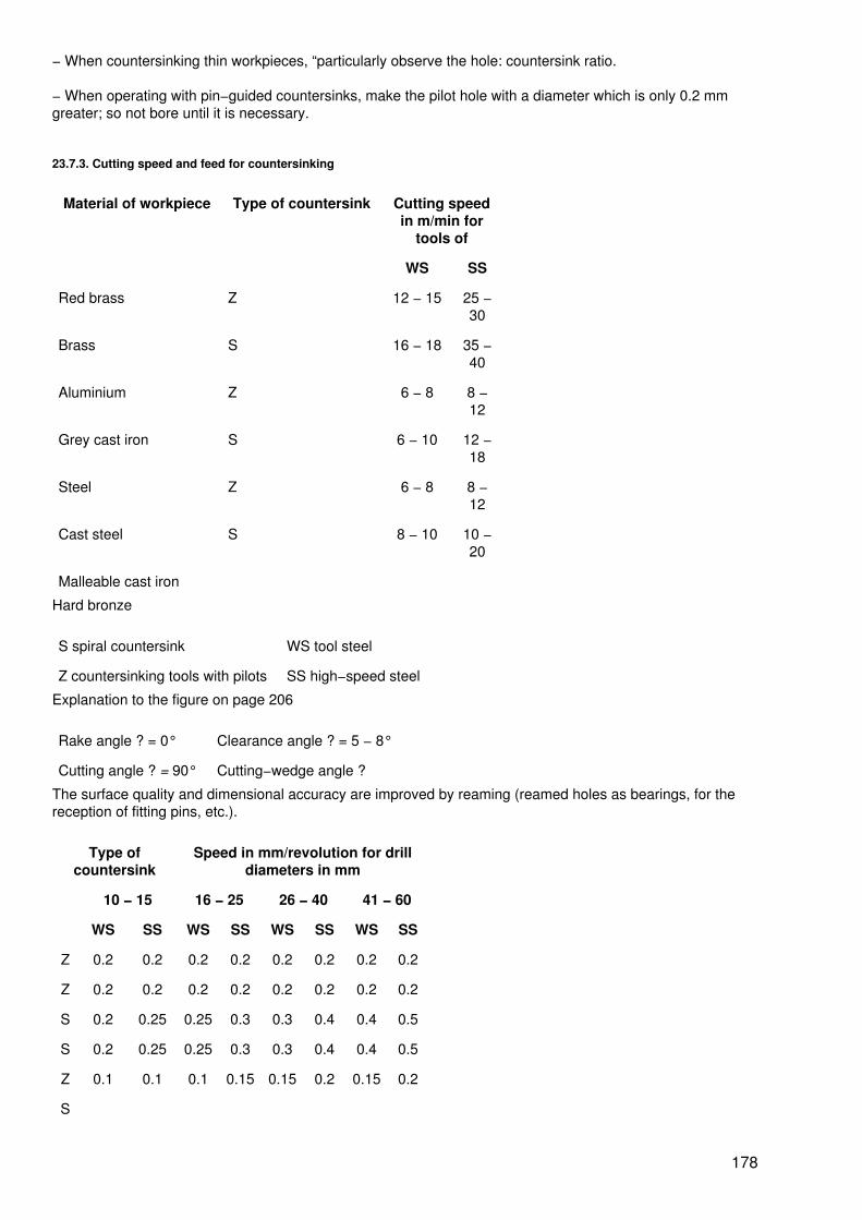
− When countersinking thin workpieces, “particularly observe the hole: countersink ratio.
− When operating with pin−guided countersinks, make the pilot hole with a diameter which is only 0.2 mmgreater; so not bore until it is necessary.
23.7.3. Cutting speed and feed for countersinking
Material of workpiece Type of countersink Cutting speedin m/min for
tools of
WS SS
Red brass Z 12 − 15 25 −30
Brass S 16 − 18 35 −40
Aluminium Z 6 − 8 8 −12
Grey cast iron S 6 − 10 12 −18
Steel Z 6 − 8 8 −12
Cast steel S 8 − 10 10 −20
Malleable cast iron
Hard bronze
S spiral countersink WS tool steel
Z countersinking tools with pilots SS high−speed steel
Explanation to the figure on page 206
Rake angle ? = 0° Clearance angle ? = 5 − 8°
Cutting angle ? = 90° Cutting−wedge angle ?
The surface quality and dimensional accuracy are improved by reaming (reamed holes as bearings, for thereception of fitting pins, etc.).
Type ofcountersink
Speed in mm/revolution for drilldiameters in mm
10 − 15 16 − 25 26 − 40 41 − 60
WS SS WS SS WS SS WS SS
Z 0.2 0.2 0.2 0.2 0.2 0.2 0.2 0.2
Z 0.2 0.2 0.2 0.2 0.2 0.2 0.2 0.2
S 0.2 0.25 0.25 0.3 0.3 0.4 0.4 0.5
S 0.2 0.25 0.25 0.3 0.3 0.4 0.4 0.5
Z 0.1 0.1 0.1 0.15 0.15 0.2 0.15 0.2
S
178

0.1to
0.15
0.15to
0.25
0.15to
0.25
0.25to
0.35
0.25to
0.35
0.35to0.4
0.35to
0.45
0.45to
0.5
23.8. Reaming
23.8.1. Design of reamers
1 Cutting direction,2 margin,3 square,4 shank,5 chamfer
23.8.2. Cutting speed and feed for reaming
Material of workpiece Reamer of tool steel high−speed steel
V in m/min s in mm/rev. V in m/min s inmm/rev.
Bronze, soft 6 − 8 0.8 − 1.5 10 − 12 0.8 − 1.5
Bronze, hard 5 − 6 0.6 − 1 8 − 10 0.6 − 1
Cast brass 20 − 25 0.8 − 2 25 − 30 1 − 2.5
Basis brass 8 − 12 0.4 − 1.2 12 − 17 1 − 2.5
Steel
up to 500 MPa 4 − 5 0.3 − 0.8 5 − 6 0.3 − 0.8
500 − 750 MPa 3 − 4 0.3 − 0.8 4 − 5 0.3 − 0.8
Grey cast iron
120 − 180 MPa 4 − 5 0.5 − 3 6 0.5 − 3
180 − 300 MPa 3 − 4 0.5 − 3 5 − 6 0.5 − 3
179
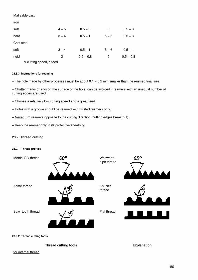
Malleable cast
iron
soft 4 − 5 0.5 − 3 6 0.5 − 3
hard 3 − 4 0.5 − 1 5 − 6 0.5 − 3
Cast steel
soft 3 − 4 0.5 − 1 5 − 6 0.5 − 1
rigid 3 0.5 − 0.8 5 0.5 − 0.8
V cutting speed, s feed
23.8.3. Instructions for reaming
− The hole made by other processes must be about 0.1 − 0.2 mm smaller than the reamed final size.
− Chatter marks (marks on the surface of the hole) can be avoided if reamers with an unequal number ofcutting edges are used.
− Choose a relatively low cutting speed and a great feed.
− Holes with a groove should be reamed with twisted reamers only.
− Never turn reamers opposite to the cutting direction (cutting edges break out).
− Keep the reamer only in its protective sheathing.
23.9. Thread cutting
23.9.1. Thread profiles
Metric ISO thread Whitworthpipe thread
Acme thread Knucklethread
Saw−tooth thread Flat thread
23.9.2. Thread cutting tools
Thread cutting tools Explanation
for internal thread
180
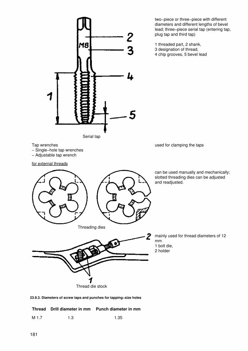
Serial tap
two−piece or three−piece with differentdiameters and different lengths of bevellead; three−piece serial tap (entering tap,plug tap and third tap)
1 threaded part, 2 shank,3 designation of thread,4 chip grooves, 5 bevel lead
Tap wrenches− Single−hole tap wrenches− Adjustable tap wrench
used for clamping the taps
for external threads
Threading dies
can be used manually and mechanically;slotted threading dies can be adjustedand readjusted.
Thread die stock
mainly used for thread diameters of 12mm1 bolt die,2 holder
23.9.3. Diameters of screw taps and punches for tapping−size holes
Thread Drill diameter in mm Punch diameter in mm
M 1.7 1.3 1.35
181

M 2.6 2.1 2.2
M 3 2.5 2.56
M 4 3.3 3.3
M 5 4.2 4.2
M 6 5 5
M 8 6.7 6.75
M 10 8.4 8.5
M 12 10 −
M 16 13.75 −
M 20 17.25 −
M 24 20.75 −
M 30 26 −
M 36 31.5 −
23.9.4. Cutting speed for cutting threads
Worked material Cutting speed in m/min for
tool steel High−speedsteel
Unalloyed steel
− up to 700 MPa 3 − 7 9 − 15
− over 700 MPa 2 − 3 5 − 8
Cast steel 2 − 3 5 − 7
Malleable cast iron 2 5 − 6
Grey cast iron
− hard 3 − 5 8 − 12
− soft 6 − 8 12 − 16
Alloyed steel
− 700 − 900 MPa 1 − 2 5 − 7
Aluminium alloys 12 − 20 20 − 30
Bronze 6 − 12 13 − 25
Magnesium 15 − 20 25 − 30
23.9.5. Instructions for cutting threads
Cutting internal threads
− Ensure proper starting of the thread tap by previous countersinking (approx. 60°, at least by one height ofpitch) of the tapping−size hole.
− Apply the thread tap vertically to the tapping−size hole.
182

− Use coolants and refrigerants in accordance with the material.
− To remove the chips and feed the lubricant, turn the thread tap back in the direction of cutting for a shorttime, then forward again.
− When cutting threads in blind holes avoid contact between the thread tap and the bottom of the drilled hole.
Cutting external threads
− Chamfer the bolt end by about 60°.
− When starting the cut, place the threading die or the thread die−stock horizontally onto the bolt end.
− Start cutting the thread with a slight pressure in the direction of the bolt, then continue cutting withoutpressure.
− Use appropriate coolants and lubricants.
− To remove the chips and feed the lubricant, turn the thread cutting tool from time to time in the oppositedirection to cutting for a short period.
23.10. Turning
23.10.1. Operating process for turning
Operating process Explanation
Longitudinal turning
Turning cutting motion (1); the tool is fed in the radialdirection (3) by cutting depth a; feed in axial direction (2);circular cylindrical faces are formed
Facing
Turning cutting motion (1); the tool is fed in the axialdirection (3) by cutting depth a; feed in radial direction(2); plane faces are formed
183
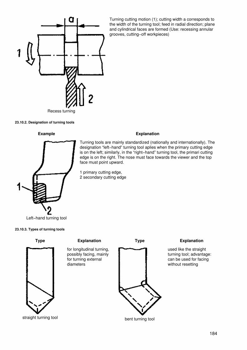
Recess turning
Turning cutting motion (1); cutting width a corresponds tothe width of the turning tool; feed in radial direction; planeand cylindrical faces are formed (Use: recessing annulargrooves, cutting−off workpieces)
23.10.2. Designation of turning tools
Example Explanation
Left−hand turning tool
Turning tools are mainly standardized (nationally and internationally). Thedesignation “left−hand” turning tool aplies when the primary cutting edgeis on the left; similarly, in the “right−hand” turning tool, the primari cuttingedge is on the right. The nose must face towards the viewer and the topface must point upward.
1 primary cutting edge,2 secondary cutting edge
23.10.3. Types of turning tools
Type Explanation Type Explanation
straight turning tool
for longitudinal turning,possibly facing, mainlyfor turning externaldiameters
bent turning tool
used like the straightturning tool; advantage:can be used for facingwithout resetting
184
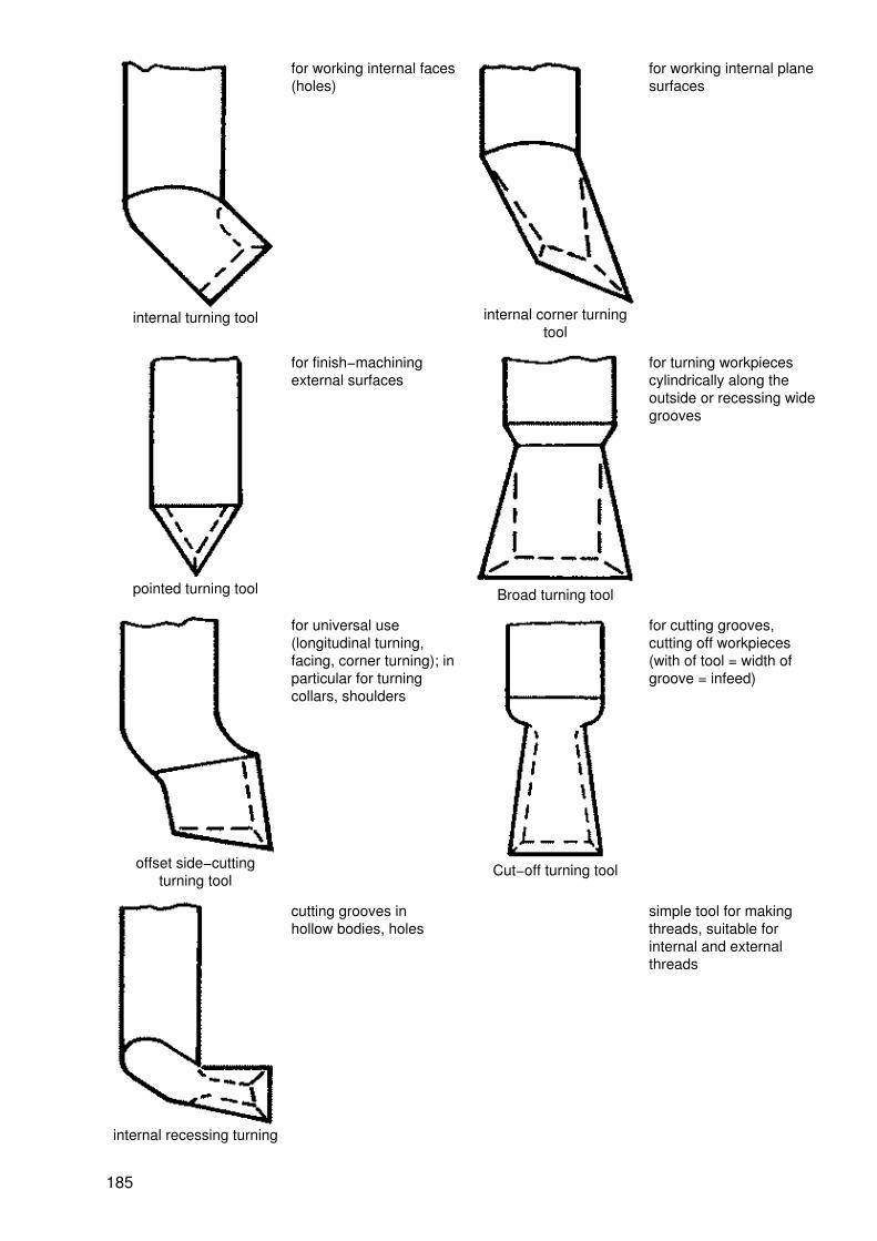
internal turning tool
for working internal faces(holes)
internal corner turningtool
for working internal planesurfaces
pointed turning tool
for finish−machiningexternal surfaces
Broad turning tool
for turning workpiecescylindrically along theoutside or recessing widegrooves
offset side−cuttingturning tool
for universal use(longitudinal turning,facing, corner turning); inparticular for turningcollars, shoulders
Cut−off turning tool
for cutting grooves,cutting off workpieces(with of tool = width ofgroove = infeed)
internal recessing turning
cutting grooves inhollow bodies, holes
simple tool for makingthreads, suitable forinternal and externalthreads
185

tool
Single−point threadingtool
23.10.4. Tool angles for turning
Turning tools of high−speed steel
Material Anglesin °
Material Anglesin °
? ? ? ?
Aluminium alloy 12 14 Bronze 8 0
Cast iron 8 0 Red brass 8 0
Fabric reinforced Pure aluminium 12 30
laminate 12 14 St 34−70 8 14
Hard rubber 12 10 St 85 8 10
White cast iron 8 0 Cast steel
Copper 8 18 − 500 MPa 8 10
− 500 to 700 MPa 8 10
Alloyed steel Malleable cast iron
− 700 to 850 MPa 8 14 8 10
− 850 to 1000 MPa 8 10
−1000 to 1800 MPa 8 6 Tool steel 8 6
Magnesium alloy 8 6 Zinc alloy 12 10
Turning tools with hard metal
Material Strength inMPa or
hardness
Rough−machininghard metal grade
Angles in ° Finish−machininghard metal
Angles in°
? ? ? grade ? ? ?
Structuralsteel
? 500 HS20, HS40 6 10 − 5− −6
HS01, HS10 6 12 −4
Cast iron ? 200 HB HG20 6 − 6 HG20, 6 6
186

0 −6
−4
> 200 HB HG10 6 0 −4
− 6 HG01, HG10 6 4 −4
White castiron
− HG10 6 0 − 6 HG10 6 0 −4
Copper − HG20 8 10−12
− 4 HG20 8 15 −4
Alloyedsteels
700 − 850 HS20, HS40 6 6 −8
− 5− −6
HS01, HS10 6 8 −4
850 − 1000 HS20, HS40 6 6 − 6− −8
HS01, HS10 6 6 −4
1000 − 1400 HS20, HS30 6 0 −4
− 8 HS01, HS10 6 4 −4
Purealuminium
− HG20 8 20 − 4 HG20 8 25 −4
Cast steel 500 − 700 HS20, HS40 6 2 −4
− 6 HS01, HS10 6 6 −4
Tool steel 1500 − 1800 HS20 6 0 − 6 HS01, HS10 6 2 −4
23.10.5. Cutting speed and feed for turning
Material to bemachined
Cutting speed in m/min for
High−speed steel Hard metal
Rough−machining Finish−machining Rough−machining Finish−machining
St 33, St 34, C 10, CK10
26 40 130 180
C 15, C 20, St 50, St 52,St 55
23 35 115 160
C 35, C 45, St 60, CK 45 20 30 100 140
C 45, C 55, C 60, St 70 17 25 90 120
Alloyed steels, tool steel 10 15 30 45
Grey cast iron 20 30 75 110
Malleable cast iron 15 22 50 75
White cast iron 10 15 20 40
Copper 50 75 250 350
Red brass 50 75 250 350
Brass 34 50 170 240
Bronze 26 40 130 180
187

Aluminium 200 300 1000 1500
Aluminium alloys 400 600 1500 2000
Aluminium alloys, hard 100 200 200 500
Aluminium−silicon−alloys 75 150 200 300
Magnesium alloys 200 400 1000 2000
Fabric reinforcedlaminate
50 150 100 200
Artificial resins 100 300 200 400
The values for the cutting speed apply to feeds of 0.5 to 2 mm per revolution (rough−machining) and 0.1 − 0.5mm per revolution (finish−machining).
23.11. Milling
23.11.1. Operating process for milling
Operating process Explanation
Up−cut milling
Milling opposite to the direction of rotation. The chip is cutat the thinnest point; the tool slides on the workpiece(bright, wavy surface)
1 cutting speed, 2 feed motion
Down−cut milling
Milling in the direction of rotation. The chip is cut at thethickest point and then torn off (dull, rough surface); highlabour productivity owing to high cutting speed and feeds
23.11.2. Types of milling cutters
188
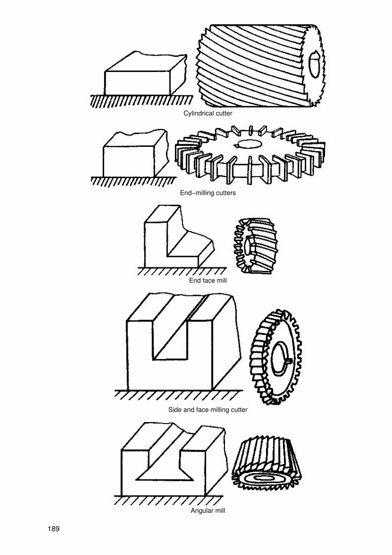
Cylindrical cutter
End−milling cutters
End face mill
Side and face milling cutter
Angular mill
189
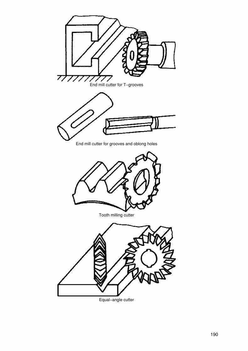
End mill cutter for T−grooves
End mill cutter for grooves and oblong holes
Tooth milling cutter
Equal−angle cutter
190

23.11.3. Cutting speed and feed for milling
Material Millingdepth in
mm
Cutting speed in m/min for
Cylindricalcutters
Endfacemills
End millcutters
Side and facemilling cutters
Formcutters
St 50, 1 24 − 30 22 − 26 20 − 24 18 − 24 18 − 22
C 35 5 22 − 28 18 − 24 18 − 22 16 − 20 16 − 20
8 18 − 22 14 − 18 14 − 18 12 − 16 12 − 16
St 70 1 20 − 22 18 − 20 18 − 20 18 − 20 −
C 60 5 16 − 20 14 − 18 16 − 18 14 − 18 14 − 18
8 14 − 16 12 − 14 14 − 16 12 − 14 13 − 14
20 Mn Cr 5 1 24 − 28 24 − 26 20 − 24 18 − 20 18 − 20
5 20 − 24 20 − 24 16 − 20 14 − 18 14 − 18
8 16 − 20 18 − 20 12 − 16 10 − 14 10 − 14
Feed in mm/ revolution 0.18 − 0.22 0.18 −0.2
0.05 −0.08
0.06 0.04
Cast steel 1 18 − 22 20 − 24 20 − 22 18 − 22 18 − 22
GS 45 5 14 − 18 14 − 22 16 − 20 14 − 18 14 − 16
8 10 − 14 12 − 14 14 − 16 10 − 14 10 − 14
Grey cast 1 18 − 22 20 − 22 20 − 22 18 − 22 16 − 20
iron 5 14 − 18 16 − 20 16 − 20 14 − 20 14 − 18
GG 18 8 10 − 14 14 − 16 14 − 16 10 − 14 10 − 14
Feed in mm/ revolution 0.2 0.18 0.06 0.08 0.05
Copper 1 45 − 60 45 − 55 45 − 55 45 − 60 45 − 60
5 30 − 50 40 − 50 30 − 50 30 − 50 25 − 40
8 25 − 35 30 − 40 24 − 30 25 − 30 20 − 25
Feed in mm/revolution 0.20 0.22 0.05 0.10 0.05
Brass 1 45 − 60 50 − 60 50 − 60 45 − 60 45 − 60
MS 72 5 30 − 50 35 − 55 35 − 55 30 − 50 30 − 60
8 25 − 35 30 − 35 30 − 35 25 − 35 25 − 30
Feed in mm/revolution 0.20 0.20 0.05 0.07 0.04
Bronze 1 45 − 55 45 − 55 50 − 60 45 − 55 40 − 45
G Cu Sn 14 5 30 − 45 35 − 50 35 − 55 30 − 45 40 − 45
8 20 − 30 30 − 35 30 − 35 20 − 30 20 − 25
Feed in mm/revolution 0.14 0.18 0.04 0.06 0.03
Pure aluminium 1 300 − 350 350 − 400 300 − 350 250 − 300
191
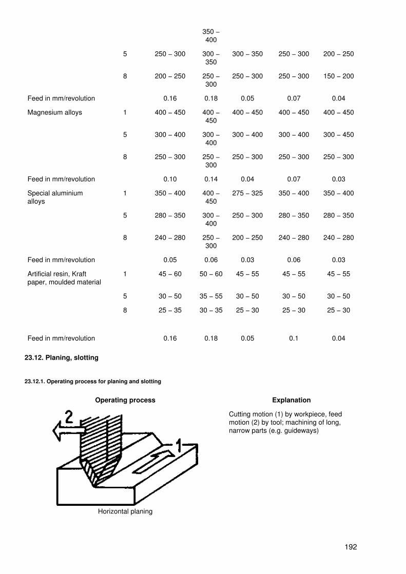
350 −400
5 250 − 300 300 −350
300 − 350 250 − 300 200 − 250
8 200 − 250 250 −300
250 − 300 250 − 300 150 − 200
Feed in mm/revolution 0.16 0.18 0.05 0.07 0.04
Magnesium alloys 1 400 − 450 400 −450
400 − 450 400 − 450 400 − 450
5 300 − 400 300 −400
300 − 400 300 − 400 300 − 450
8 250 − 300 250 −300
250 − 300 250 − 300 250 − 300
Feed in mm/revolution 0.10 0.14 0.04 0.07 0.03
Special aluminiumalloys
1 350 − 400 400 −450
275 − 325 350 − 400 350 − 400
5 280 − 350 300 −400
250 − 300 280 − 350 280 − 350
8 240 − 280 250 −300
200 − 250 240 − 280 240 − 280
Feed in mm/revolution 0.05 0.06 0.03 0.06 0.03
Artificial resin, Kraftpaper, moulded material
1 45 − 60 50 − 60 45 − 55 45 − 55 45 − 55
5 30 − 50 35 − 55 30 − 50 30 − 50 30 − 50
8 25 − 35 30 − 35 25 − 30 25 − 30 25 − 30
Feed in mm/revolution 0.16 0.18 0.05 0.1 0.04
23.12. Planing, slotting
23.12.1. Operating process for planing and slotting
Operating process Explanation
Horizontal planing
Cutting motion (1) by workpiece, feedmotion (2) by tool; machining of long,narrow parts (e.g. guideways)
192

Horizontal slotting
Cutting motion (1) by tool, feed motion(2) by workpiece; machining of individualparts, smaller workpieces
Vertical slotting
Cutting motion (1) by tool, feed motion(2) by workpiece; finishing of openingsand grooves when the hole alreadyexists
23.12.2. Types of planing tools
Straight and bent planing tool
193

Side planeMachining vertical surfaces andsharp−edged shoulders
Cutting planeProduction of U−shaped grooves withlow requirements made on the surfacequality
Grooving planeProduction of T−shaped grooves with lowrequirements made on the surfacequality
194

Angle planeMaking acute−angled corners, sharpshoulders and dovetail grooves
23.12.3. Cutting speed and feed for planing and slotting (high−speed tool steel)
Material Characteristics Cutting speed perdouble stroke in mm
in m/min when planing with feed
0.16 0.20 0.25 0.32 0.40 0.50 0.63 0.80 1.0 1.2 1.6 2.0
St 38. St42 ?60 42 39 36 34 32 30 27 25 24 22 21 19
C 15, C 22 ?120 33 31 29 27 25 23 22 20 19 18 17 16
St50, C35 ?60 32 30 27 26 24 22 21 19 18 17 16 14
?120 26 23 22 20 19 18 16 14 13 12 12 11
St60, C45 ?60 24 23 21 20 19 17 16 15 14 13 12 11
?120 20 19 18 16 15 14 13 13 12 11 10 9
St70, C60 ?60 21 19 18 17 16 15 14 13 12 11 10 9
?120 16 15 14 13 12 11 10 10 9 9 8 7
Cast steel ?60 33 31 28 26 24 23 21 19 18 17 16 15
GS−38 ?120 27 25 23 21 20 18 17 16 15 14 13 12
Cast steel ?60 26 24 22 21 19 18 17 15 14 13 12 11
GS−45 ?120 21 20 18 17 15 14 13 12 12 11 10 9
Cast steel ?60 20 19 18 16 15 14 13 12 11 10 9 8
GS−52 ?120 17 15 14 13 12 11 11 10 9 8 8 7
Grey cast ?60 44 40 36 32 28 25 22 20 18 16 15 13
iron GG−12 ?120 36 32 29 26 23 21 18 16 15 13 12 11
GG−14
GG−18 ?60 30 27 24 22 20 18 16 14 13 11 10 9
GG−22 ?120 25 23 20 18 16 15 13 12 11 10 9 8
?60 and ?120 are service lives of 60 minutes and 120 minutes, resp. Planing at ?60corresponds to slotting at ?30; planing at ?120 corresponds to slotting at ?60.
195

23.13. Broaching
23.13.1. Broaching tools
Internal broach
1 shank, 2 roughing teeth, 3 finishing teeth, 4 burnishing part, 5 end piece
The design of the broaching tools depends
− on the workpiece (material, broaching length, space cross−section).
− on the machine used.
The tool (internal or external broach) is drawn or pressed through or over the workpiece horizontally orvertically.
23.13.2. Cutting speed for broaching
Material Cutting speed in m/min
Internal broaching External broaching
Al alloys 10 − 14 10 − 16
Cast iron 6−8 8−10
White cast iron 1 1
Brass 8−10 8−12
Steel, medium 4−8 6−10
tough 2−4 4−6
Malleable cast iron 4−8 8−10
23.14. Grinding
23.14.1. Operating process for grinding
Operating process Explanation
Cylindrical grinding Cylindrical grinding is used for rotationally symmetrical internaland external surfaces;1 cutting motion, 2 feed motion. 3 in−feed movement, 4movement of the workpiece
196

Longitudinal grinding
Plunge−cut grinding
Flat grinding
Peripheral grinding
Flat grinding is used to grind plane surfaces, e.g.: internal andexternal guides, sliding and running surfaces, sealing surfaces,cutting edges of tools, toothed gears1 cutting speed, 2 feed motion, 3 in−feed movement
197
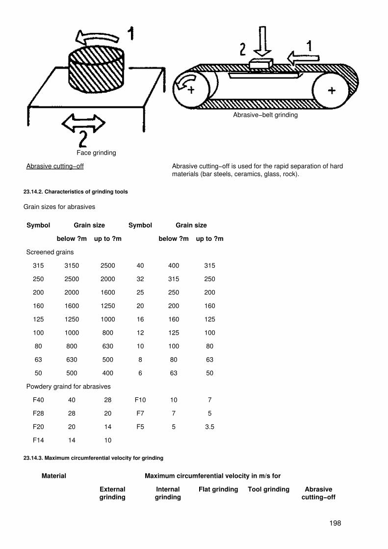
Face grinding
Abrasive−belt grinding
Abrasive cutting−off Abrasive cutting−off is used for the rapid separation of hardmaterials (bar steels, ceramics, glass, rock).
23.14.2. Characteristics of grinding tools
Grain sizes for abrasives
Symbol Grain size Symbol Grain size
below ?m up to ?m below ?m up to ?m
Screened grains
315 3150 2500 40 400 315
250 2500 2000 32 315 250
200 2000 1600 25 250 200
160 1600 1250 20 200 160
125 1250 1000 16 160 125
100 1000 800 12 125 100
80 800 630 10 100 80
63 630 500 8 80 63
50 500 400 6 63 50
Powdery graind for abrasives
F40 40 28 F10 10 7
F28 28 20 F7 7 5
F20 20 14 F5 5 3.5
F14 14 10
23.14.3. Maximum circumferential velocity for grinding
Material Maximum circumferential velocity in m/s for
Externalgrinding
Internalgrinding
Flat grinding Tool grinding Abrasivecutting−off
198
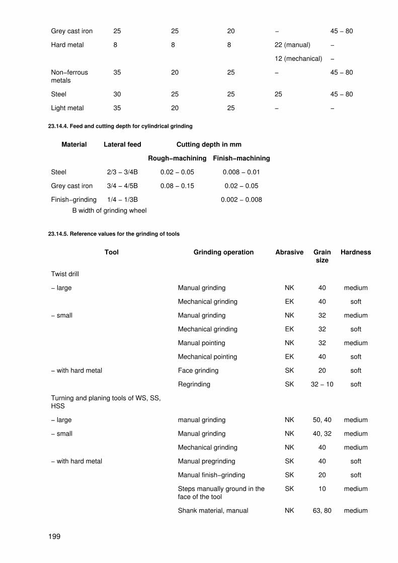
Grey cast iron 25 25 20 − 45 − 80
Hard metal 8 8 8 22 (manual) −
12 (mechanical) −
Non−ferrousmetals
35 20 25 − 45 − 80
Steel 30 25 25 25 45 − 80
Light metal 35 20 25 − −
23.14.4. Feed and cutting depth for cylindrical grinding
Material Lateral feed Cutting depth in mm
Rough−machining Finish−machining
Steel 2/3 − 3/4B 0.02 − 0.05 0.008 − 0.01
Grey cast iron 3/4 − 4/5B 0.08 − 0.15 0.02 − 0.05
Finish−grinding 1/4 − 1/3B 0.002 − 0.008
B width of grinding wheel
23.14.5. Reference values for the grinding of tools
Tool Grinding operation Abrasive Grainsize
Hardness
Twist drill
− large Manual grinding NK 40 medium
Mechanical grinding EK 40 soft
− small Manual grinding NK 32 medium
Mechanical grinding EK 32 soft
Manual pointing NK 32 medium
Mechanical pointing EK 40 soft
− with hard metal Face grinding SK 20 soft
Regrinding SK 32 − 10 soft
Turning and planing tools of WS, SS,HSS
− large manual grinding NK 50, 40 medium
− small Manual grinding NK 40, 32 medium
Mechanical grinding NK 40 medium
− with hard metal Manual pregrinding SK 40 soft
Manual finish−grinding SK 20 soft
Steps manually ground in theface of the tool
SK 10 medium
Shank material, manual NK 63, 80 medium
199

mechanical NK 63, 80 soft
Milling cutters of WS, SS, HSS EK 32 soft
EK 32 soft
− with hard metal Pregrinding SK 32 soft
Finish−grinding SK 20 soft
Band saw blades EK 32 medium
Saw blades of metal circular saws EK 40,32 soft
Gauges and devices EK 32,20 soft
EK special fused alumina, NK standardcorundum, SK silicon carbide
Ceramic is used as a binding agent
23.14.6. Instructions for grinding
− Use soft abrasives for hard materials and hard abrasives for soft materials.
− Check the parameters of the abrasives (maximum circumferential velocity, binding agent, grade) beforeinstalling them in the machine.
− When mounting the grinding wheels, take care that compensating shims (of cardboard or leather) areplaced on both sides.
− With grinding wheels, use only the faces for grinding,
− When grinding, use an eye protection device or safety goggles.
− Allow rotating grinding wheels to come to rest; do not brake them manually.
23.15. General data on cutting
23.15.1. Angles, surfaces and cutting edges of tools
Angle, surface, cutting edge Explanation
Cutting−wedge angle ?. Dependson the material of the wedge ofthe cutting edge and of theworkpiece. Large cutting−wedgeangle for solid materials and poorheat conductors.Clearance angle ?. Ensurescutting effect, large clearanceangle − good cut but reducedstrength of the wedge of thecutting edge and poorer heatremoval.
200
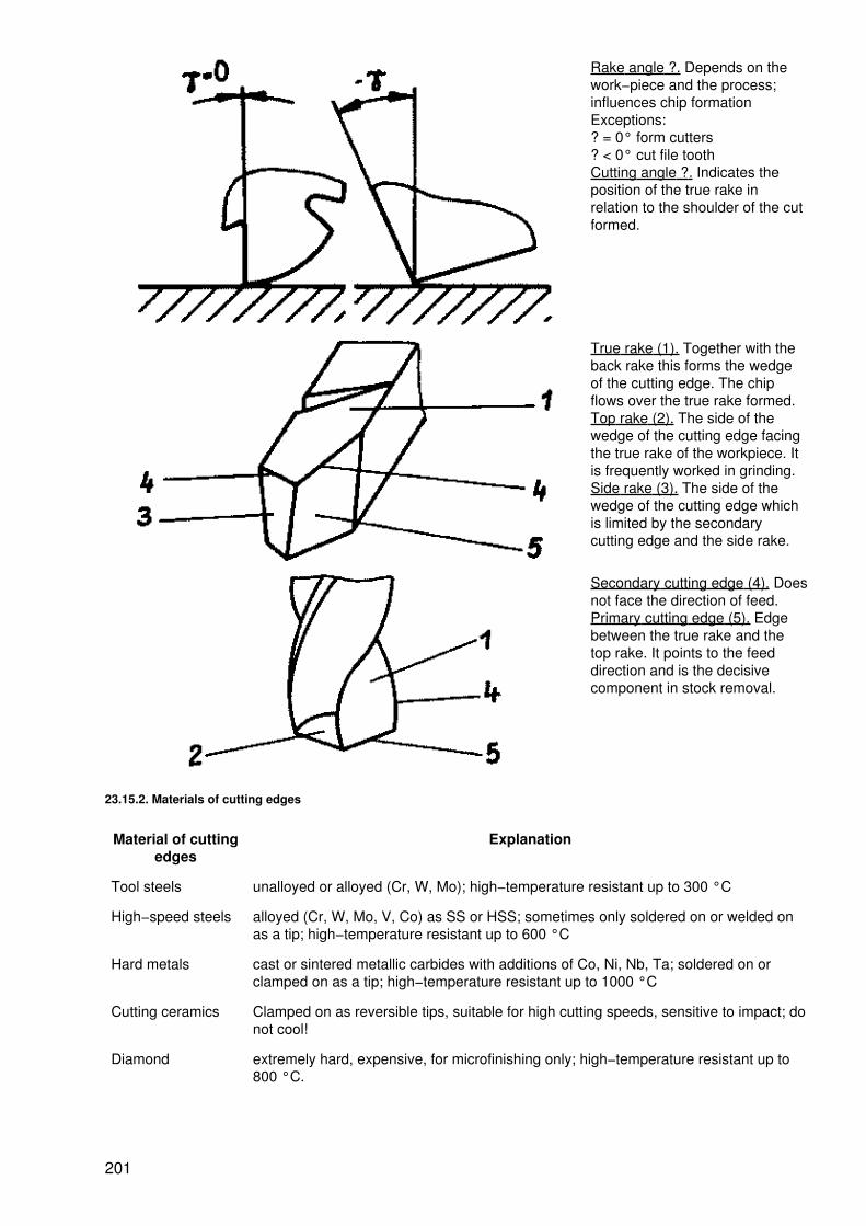
Rake angle ?. Depends on thework−piece and the process;influences chip formationExceptions:? = 0° form cutters? < 0° cut file toothCutting angle ?. Indicates theposition of the true rake inrelation to the shoulder of the cutformed.
True rake (1). Together with theback rake this forms the wedgeof the cutting edge. The chipflows over the true rake formed.Top rake (2). The side of thewedge of the cutting edge facingthe true rake of the workpiece. Itis frequently worked in grinding.Side rake (3). The side of thewedge of the cutting edge whichis limited by the secondarycutting edge and the side rake.
Secondary cutting edge (4). Doesnot face the direction of feed.Primary cutting edge (5). Edgebetween the true rake and thetop rake. It points to the feeddirection and is the decisivecomponent in stock removal.
23.15.2. Materials of cutting edges
Material of cuttingedges
Explanation
Tool steels unalloyed or alloyed (Cr, W, Mo); high−temperature resistant up to 300 °C
High−speed steels alloyed (Cr, W, Mo, V, Co) as SS or HSS; sometimes only soldered on or welded onas a tip; high−temperature resistant up to 600 °C
Hard metals cast or sintered metallic carbides with additions of Co, Ni, Nb, Ta; soldered on orclamped on as a tip; high−temperature resistant up to 1000 °C
Cutting ceramics Clamped on as reversible tips, suitable for high cutting speeds, sensitive to impact; donot cool!
Diamond extremely hard, expensive, for microfinishing only; high−temperature resistant up to800 °C.
201
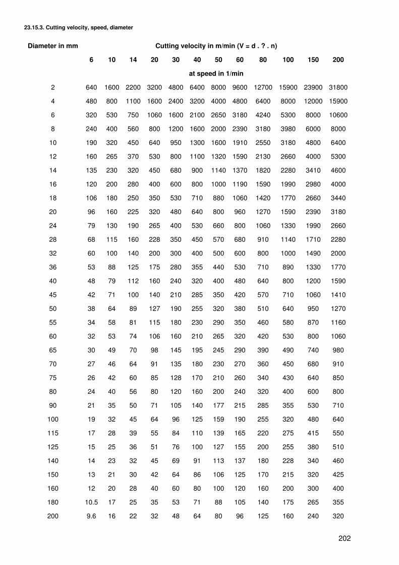
23.15.3. Cutting velocity, speed, diameter
Diameter in mm Cutting velocity in m/min (V = d . ? . n)
6 10 14 20 30 40 50 60 80 100 150 200
at speed in 1/min
2 640 1600 2200 3200 4800 6400 8000 9600 12700 15900 23900 31800
4 480 800 1100 1600 2400 3200 4000 4800 6400 8000 12000 15900
6 320 530 750 1060 1600 2100 2650 3180 4240 5300 8000 10600
8 240 400 560 800 1200 1600 2000 2390 3180 3980 6000 8000
10 190 320 450 640 950 1300 1600 1910 2550 3180 4800 6400
12 160 265 370 530 800 1100 1320 1590 2130 2660 4000 5300
14 135 230 320 450 680 900 1140 1370 1820 2280 3410 4600
16 120 200 280 400 600 800 1000 1190 1590 1990 2980 4000
18 106 180 250 350 530 710 880 1060 1420 1770 2660 3440
20 96 160 225 320 480 640 800 960 1270 1590 2390 3180
24 79 130 190 265 400 530 660 800 1060 1330 1990 2660
28 68 115 160 228 350 450 570 680 910 1140 1710 2280
32 60 100 140 200 300 400 500 600 800 1000 1490 2000
36 53 88 125 175 280 355 440 530 710 890 1330 1770
40 48 79 112 160 240 320 400 480 640 800 1200 1590
45 42 71 100 140 210 285 350 420 570 710 1060 1410
50 38 64 89 127 190 255 320 380 510 640 950 1270
55 34 58 81 115 180 230 290 350 460 580 870 1160
60 32 53 74 106 160 210 265 320 420 530 800 1060
65 30 49 70 98 145 195 245 290 390 490 740 980
70 27 46 64 91 135 180 230 270 360 450 680 910
75 26 42 60 85 128 170 210 260 340 430 640 850
80 24 40 56 80 120 160 200 240 320 400 600 800
90 21 35 50 71 105 140 177 215 285 355 530 710
100 19 32 45 64 96 125 159 190 255 320 480 640
115 17 28 39 55 84 110 139 165 220 275 415 550
125 15 25 36 51 76 100 127 155 200 255 380 510
140 14 23 32 45 69 91 113 137 180 228 340 460
150 13 21 30 42 64 86 106 125 170 215 320 425
160 12 20 28 40 60 80 100 120 160 200 300 400
180 10.5 17 25 35 53 71 88 105 140 175 265 355
200 9.6 16 22 32 48 64 80 96 125 160 240 320
202
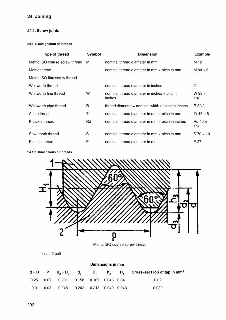
24. Joining
24.1. Screw joints
24.1.1. Designation of threads
Type of thread Symbol Dimension Example
Metric ISO coarse screw thread M nominal thread diameter in mm M 12
Metric thread nominal thread diameter in mm × pitch in mm M 80 × 6
Metric ISO fine screw thread
Whitworth thread − nominal thread diameter in inches 2”
Whitworth fine thread W nominal thread diameter in inches × pitch ininches
W 99 ×1/4”
Whitworth pipe thread R thread diameter = nominal width of pipe in inches R 3/4”
Acme thread Tr nominal thread diameter in mm × pitch in mm Tr 48 × 8
Knuckle thread Rd nominal thread diameter in mm × pitch in inches Rd 40 ×1/6”
Saw−tooth thread S nominal thread diameter in mm × pitch in mm S 70 × 10
Electric thread E nominal thread diameter in mm E 27
24.1.2. Dimensions of threads
Metric ISO coarse screw thread
1 nut, 2 bolt
Dimensions in mm
d = D P d2 = D2 d3 D1 h3 H1 Cross−sect ion of tap in mm2
0.25 0.07 0.201 0.158 0.169 0.046 0.041 0.02
0.3 0.08 0.248 0.202 0.213 0.049 0.043 0.032
203

0.4 0.1 0.335 0.277 0.292 0.061 0.054 0.06
0.5 0.125 0.419 0.347 0.365 0.077 0.068 0.095
0.6 0.15 0.503 0.416 0.438 0.092 0.081 0.136
0.8 0.2 0.67 0.555 0.583 0.123 0.108 0.242
1 0.25 0.838 0.693 0.729 0.153 0.135 0.377
1.2 0.25 1.038 0.893 0.929 0.153 0.135 0.626
1.6 0.35 1.373 1.171 1.221 0.215 0.189 0.08
2 0.4 1.740 1.509 1.57 0.245 0.217 1.79
2.5 0.45 2.208 1.948 2.03 0.276 0.244 2.98
3 0.5 2.675 2.387 2.459 0.307 0.271 4.47
4 0.7 3.545 3.141 3.242 0.429 0.379 7.75
5 0.8 4.480 4.019 4.134 0.491 0.433 12.7
6 1. 5.350 4.773 4.917 0.613 0.541 17.9
8 1.25 7.188 6.466 6.647 0.767 0.677 32.8
10 1.5 9.026 8.160 8.376 0.920 0.812 52.3
12 1.75 10.863 9.853 10.106 1.074 0.947 76.2
16 2 14.701 13.546 13.835 1.227 1.083 144
20 2.5 18.376 16.933 17.294 1.534 1.353 255
24 3 22.051 20.319 20.752 1.840 1.624 324
30 3.5 27.727 25.706 26.211 2.147 1.894 519
36 4 33.402 31.093 31.670 2.454 2.165 759
42 4.5 39.077 36.479 37.129 2.760 2.436 1045
48 5 44.752 41.866 42.587 3.067 2.706 1377
56 5.5 52.428 49.252 50.046 3.374 2.977 1905
64 6 60.103 56.639 57.505 3.681 3.248 2520
Metric ISO fine screw thread
Dimensions in mm
d = D P d2 = D2 d3 D1 h3 H1 Cross−section of tap in mm2
1 0.2 0.870 0.755 0.783 0.123 0.108 0.448
1.6 1.470 1.355 1.383 1.44
2 0.25 1.838 1.693 1.729 0.153 0.135 2.25
2.5 0.35 2.273 2.071 2.121 0.215 0.189 3.37
4 0.5 3.675 3.387 3.459 0.307 0.271 9.01
6 5.675 5.387 5.459 22.8
10 9.675 9.387 9.459 69.2
16 15.675 15.387 15.459 186
204
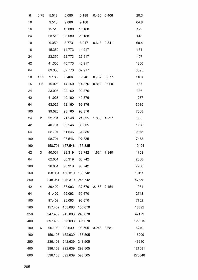
6 0.75 5.513 5.080 5.188 0.460 0.406 20.3
10 9.513 9.080 9.188 64.8
16 15.513 15.080 15.188 179
24 23.513 23.080 23.188 418
10 1 9.350 8.773 8.917 0.613 0.541 60.4
16 15.350 14.773 14.917 171
24 23.350 22.773 22.917 407
42 41.350 40.773 40.917 1306
64 63.350 62.773 62.917 3095
10 1.25 9.188 8.466 8.646 0.767 0.677 56.3
16 1.5 15.026 14.160 14.376 0.812 0.920 157
24 23.026 22.160 22.376 386
42 41.026 40.160 40.376 1267
64 63.026 62.160 62.376 3035
100 99.026 98.160 98.376 7568
24 2 22.701 21.546 21.835 1.083 1.227 365
42 40.701 39.546 39.835 1228
64 62.701 61.546 61.835 2975
100 98.701 97.546 97.835 7473
160 158.701 157.546 157.835 19494
42 3 40.051 38.319 38.742 1.624 1.840 1153
64 62.051 60.319 60.742 2858
100 98.051 96.319 96.742 7286
160 158.051 156.319 156.742 19192
250 248.051 246.319 246.742 47652
42 4 39.402 37.093 37.670 2.165 2.454 1081
64 61.402 59.093 59.670 2743
100 97.402 95.093 95.670 7102
160 157.402 155.093 155.670 18892
250 247.402 245.093 245.670 47179
400 397.402 395.093 395.670 122615
100 6 96.103 92.639 93.505 3.248 3.681 6740
160 156.103 152.639 153.505 18299
250 236.103 242.639 243.505 46240
400 396.103 292.639 293.505 121081
600 596.103 592.639 593.505 275848
205
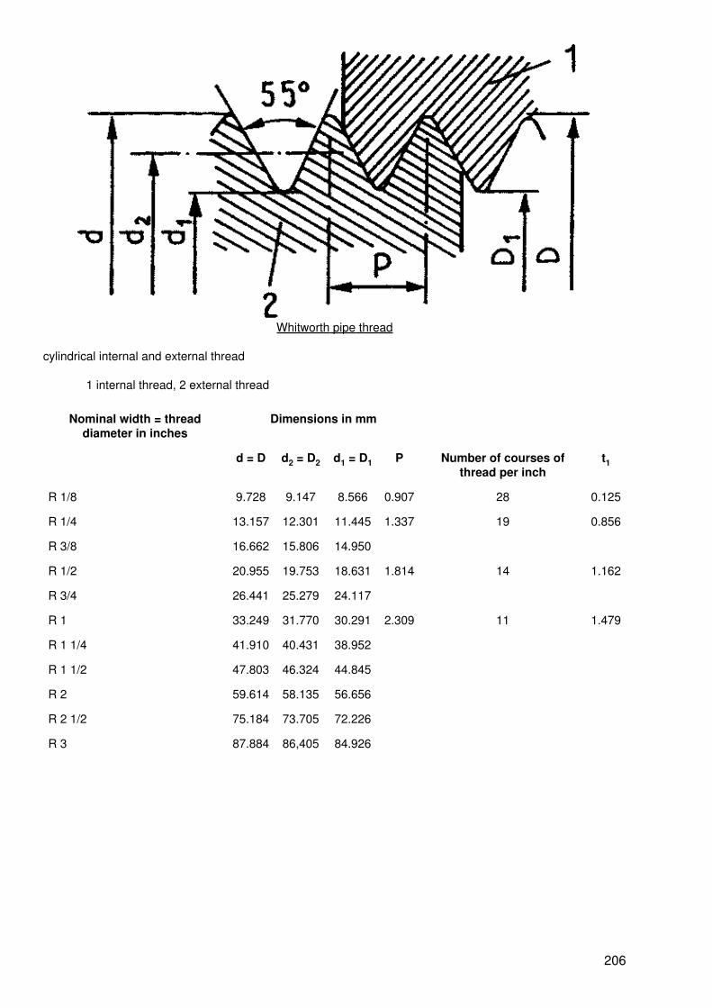
Whitworth pipe thread
cylindrical internal and external thread
1 internal thread, 2 external thread
Nominal width = threaddiameter in inches
Dimensions in mm
d = D d2 = D2 d1 = D1 P Number of courses ofthread per inch
t1
R 1/8 9.728 9.147 8.566 0.907 28 0.125
R 1/4 13.157 12.301 11.445 1.337 19 0.856
R 3/8 16.662 15.806 14.950
R 1/2 20.955 19.753 18.631 1.814 14 1.162
R 3/4 26.441 25.279 24.117
R 1 33.249 31.770 30.291 2.309 11 1.479
R 1 1/4 41.910 40.431 38.952
R 1 1/2 47.803 46.324 44.845
R 2 59.614 58.135 56.656
R 2 1/2 75.184 73.705 72.226
R 3 87.884 86,405 84.926
206

Acme thread, single−start thread
Bolt (2):
minor diameter d1 = d − 2t1Flank diameter d2 = d − 0.5p
Nut (1):
external diameterb = d + 2aminor diameterD1 = d2 + 2bt11 = 02.5 P + a
Dimensions in mm
Nominal thread diameter of the bolt
fine medium coarse P t1 t2 a b T1
10 − 20 − − 2 1.25 0.75 0.25 0.5 1
22 − 62 10 − 12 − 3 1.75 1.25 0.25 0.5 1.5
65 − 110 14 − 20 − 4 2.25 1.75 0.25 0.5 2
− 22 − 28 − 5 2.75 2 0.25 0.75 2.25
115 − 175 30 − 36 − 6 3.25 2.5 0.25 0.75 2.75
− 38 − 44 − 7 3.75 3 0.25 0.75 3.25
180 − 240 46 − 52 22 − 28 8 4.25 3.5 0.25 0.75 3.75
− 55 − 62 − 9 4.75 4 0.25 0.75 4.25
− 65 − 82 30 − 38 10 5.25 4.5 0.25 0.75 4.75
207

250 − 400 85 − 110 40 − 52 12 6.25 5.5 0.25 0.75 5.75
− 115 − 145 55 − 62 14 7.5 6 0.5 1.5 6.5
− 150 − 175 65 − 82 16 8.5 7 0.5 1.5 7.5
420 − 500 180 − 200 85 − 98 18 9.5 8 0.5 1.5 8.5
− 210 − 230 100 − 110 20 10.5 9 0.5 1.5 9.5
− 240 − 260 115 − 130 22 11.5 10 0.5 1.5 10.5
520 − 640 270 − 290 135 − 155 24 12.5 11 0.5 1.5 11.5
− 300 − 26 13.5 12 0.5 1.5 12.5
− − 160 − 180 28 14.5 13 0.5 1.5 13.5
− − 185 − 200 32 16.5 15 0.5 1.5 15.5
− − 210 − 240 36 18.5 17 0.5 1.5 17.5
− − 250 − 280 40 20.5 19 0.5 1.5 19.5
− − 290 − 340 44 22.5 21 0.5 1.5 21.5
− − 360 − 400 48 24.5 23 0.5 1.5 23.5
Multiple threads are provided with the corresponding multiple pitch with the thread profile belonging to thesingle−start thread.
Knuckle thread
1 nut, 2 boltr = 0.23851 PR1 = 0.22105 P� = diameter
Dimensions in mm
Nominal diameterof thread d
Number of courses ofthread per inch
Pitch Depth ofthread t1
Bearingdepth t2
Roundings ofnuts R
8 − 12 10 2.54 1.270 0.212 0.650
14 − 38 8 3.17 1.588 0.265 0.813
208

40 − 100 6 4.2 2.117 0.353 1.084
105 − 200 4 6.3 3.175 0.530 1.625
Dimensions of the nut in mm
Thread diameter D Minor diameter D1 Thread diameter D Minor diameter D1
8.245 5.714 44.423 40.190
9.254 6.714 48.423 44.190
10.254 7.714 52.423 48.190
11.254 8.714 55.423 51.190
12.254 9.714 60.423 56.190
14.318 11.142 95.423 91.190
16.318 13.142 100.423 96.190
32.318 29.142 110.635 104.285
36.318 33.142 120.635 114.285
40.423 36.190 200.635 194.285
Dimensions of the bolt in mm
Thread diameter d Minor diameter d1 Cross−section of tap A in mm Flank diameter d2
8 5.460 0.234 6.730
9 6.460 0.328 7.730
10 7.460 0.437 8.730
11 8.460 0.562 9.730
12 9.460 0.703 10.730
14 10.825 0.920 12.412
16 12.825 1.292 14.412
32 28.825 6.526 30.412
36 32.825 8.463 34.412
40 35.767 10.05 37.883
44 39.767 12.42 42.883
48 43.767 15.05 45.883
52 47.767 17.92 49.883
55 50.767 20.24 52.883
60 55.767 24.43 57.883
95 90.767 64.71 92.883
100 95.767 72.03 97.883
110 103.650 84.38 106.825
120 113.650 101.45 116.825
200 193.650 294.5 196.825
209
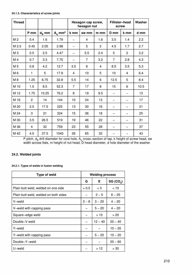
24.1.3. Characteristics of screw joints
Thread Hexagon cap screw,hexagon nut
Fillister−headscrew
Washer
P mm dB mm Aq mm2 k mm sw mm m mm D mm k mm d mm
M 2 0.4 1.6 1.79 − 4 1.6 3.5 1.4 2.2
M 2.5 0.45 2.05 2.98 − 5 2 4.5 1.7 2.7
M 3 0.5 2.5 4.47 − 5.5 2.4 5 2 3.2
M 4 0.7 3.3 7.75 − 7 3.2 7 2.8 4.3
M 5 0.8 4.2 12.7 3.5 8 4 8.5 3.5 5.3
M 6 1 5 17.9 4 10 5 10 4 6.4
M 8 1.25 6.75 32.8 5.5 14 6 12.5 5 8.4
M 10 1.5 8.5 52.3 7 17 8 15 6 10.5
M 12 1.75 10.25 76.2 8 19 9.5 − − 13
M 16 2 14 144 10 24 13 − − 17
M 20 2.5 17.5 225 13 30 16 − − 21
M 24 3 21 324 15 36 18 − − 25
M 30 3.5 26.5 519 19 46 22 − − 31
M 36 4 32 759 23 55 28 − − 37
M 42 4.5 37.5 1045 26 65 32 − − 43
P pitch, dB drill diameter for core hole, Aq cross−section of tap, k height of screw head, swwidth across flats, m height of nut head, D head diameter, d hole diameter of the washer
24.2. Welded joints
24.2.1. Types of welds in fusion welding
Type of weld Welding process
G E SG (CO2)
Plain butt weld, welded on one side > 0.5 < 3 < 10
Plain butt weld, welded on both sides − 2 − 5 6 − 25
V−weld 3 − 8 3 − 20 4 − 20
V−weld with capping pass − 5 − 20 4 − 20
Square−edge weld − > 10 > 20
Double−V weld − 12 − 40 20 − 40
Y−weld − − 10 − 20
Y−weld with capping pass − 5 − 20 10 − 20
Double−Y−weld − − 20 − 60
U−weld − > 12 > 30
210

U−weld with capping pass − > 12 > 30
Double U weld − > 30 > 50
Double bevel butt weld − 12 − 40 >15
Single bevel butt weld − 3 − 20 3 − 20
Single bevel butt weld, welded on both sides − 3 − 20 3 − 20
Single−J butt weld − > 15 > 20
Double−3 butt weld − > 30 > 40
Fillet weld > 1 > 1 > 1
Double fillet weld > 2 > 2 > 2
Edge joint weld > 2 > 2 > 2
Flange weld > 4 > 4 > 4
Edge groove weld > 3 > 4 > 4
Corner weld > 1 > 2 > 2
G oxyacetylene welding, E electric welding, SG(CO2) inert−gas arc welding
24.2.2. Symbols for fusion welding
WeldDesignation
Section (graphic) View (symbolic) Symbol
Butweld
General S
Plain buttweld
||
V−weld V
211

DoubleV−weld
X
Y−weld Y
Filletweld
Fillet weld
Double filletweld
Corner weld
Edge jointweld
|||
Edge grooveweld
212

24.2.3. Fusion welding processes
Process Symbol Process Symbol
Oxyacetylene welding G Gas−shielded arc welding SG
Electric arc welding E Submerged−arc welding UP
TIG welding TIG Firecracker welding US
MIG welding MIG Electroslag welding ES
Process Use Positions Plate and wall thicknesses
G Steel and non−ferrous metals all positions small thickness
E preferably steel all positions greater thickness
WIG aluminium and alloys all positions small thickness
TIG high−alloy steel all positions thickness > 4 mm
SG unalloyed and low Mn−alloy steel all positions all thicknesses
US steel horizontal small thickness
UP preferably steel horizontal great thickness
ES steel upward thickness > 12 mm
24.2.4. Resistance spot welding of unalloyed steels
Dimensions in mm
Individualplate
thickness
Electrodediameter
(min.)
Electrodetip
diameter(max.)
Spotdiameter
(min.)
Electrodeforce in
kN
Weldcurrentin kA
Overlapping Min. spotspacing with
regard to
Spotshear
strengthin kN/spot
shunt strength
0.4 8 4 3.2 1 5 8 9 6 1
0.6 10 5 3.8 1.5 7 10 12 8 2
0.8 10 6 4.4 2 8 11 15 9 3
1.0 13 6 5.0 2.5 9 13 18 10 4
1.2 13 8 5.5 3.0 10 14 20 11 5.25
1.4 13 8 6.0 3.5 11 15 23 12 6.5
1.6 13 8 6.4 4.0 12 16 26 13 8
1.8 16 8 6.7 4.5 13 17 28 13 9.7
2.0 16 8 7.0 5.0 14 18 30 14 11.5
2.2 16 10 7.4 5.5 15 18 32 15 13
2.4 16 10 7.7 6.0 16 19 34 15 15
2.6 16 10 8.0 6.5 17 20 36 16 17
2.8 20 10 8.3 7.0 18 21 38 17 19
3.0 20 10 8.6 7.5 19 22 40 17 21
213

3.2 20 10 8.9 8.0 20 22 42 18 23
24.2.5. Symbols for pressure welding
Weld Designation Symbol View (symbolic) Section(graphic)
single−row
double−row
staggered
continuous
interrupted
214

projection in the top plate
projection in the bottomplate
mash weld
burr weld
reinforced weld
24.3. Riveted joints
24.3.1. Arrangements of rivets
Designation Figure
215
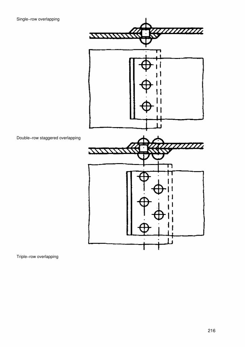
Single−row overlapping
Double−row staggered overlapping
Triple−row overlapping
216
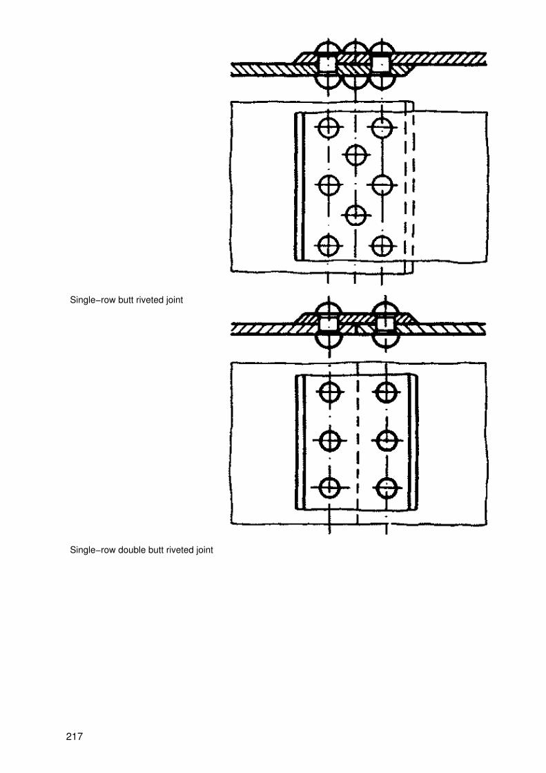
Single−row butt riveted joint
Single−row double butt riveted joint
217

double−row double butt riveted joint
24.3.2. Dimensions of rivets
218
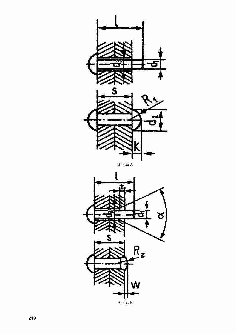
Shape A
Shape B
219
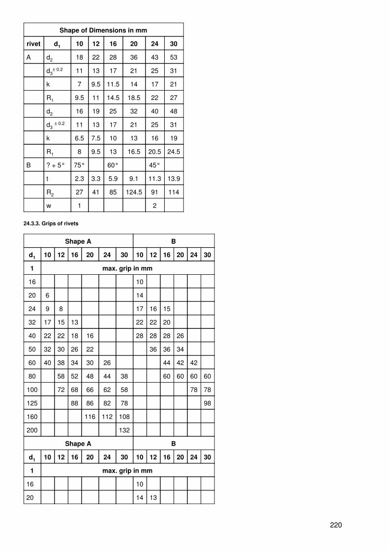
Shape of Dimensions in mm
rivet d1 10 12 16 20 24 30
A d2 18 22 28 36 43 53
d3± 0.2 11 13 17 21 25 31
k 7 9.5 11.5 14 17 21
R1 9.5 11 14.5 18.5 22 27
d2 16 19 25 32 40 48
d3± 0.2 11 13 17 21 25 31
k 6.5 7.5 10 13 16 19
R1 8 9.5 13 16.5 20.5 24.5
B ? + 5° 75° 60° 45°
t 2.3 3.3 5.9 9.1 11.3 13.9
R2 27 41 85 124.5 91 114
w 1 2
24.3.3. Grips of rivets
Shape A B
d1 10 12 16 20 24 30 10 12 16 20 24 30
1 max. grip in mm
16 10
20 6 14
24 9 8 17 16 15
32 17 15 13 22 22 20
40 22 22 18 16 28 28 28 26
50 32 30 26 22 36 36 34
60 40 38 34 30 26 44 42 42
80 58 52 48 44 38 60 60 60 60
100 72 68 66 62 58 78 78
125 88 86 82 78 98
160 116 112 108
200 132
Shape A B
d1 10 12 16 20 24 30 10 12 16 20 24 30
1 max. grip in mm
16 10
20 14 13
220

24 6 17 16
32 13 10 22 22 20
40 19 17 13 28 28 28 26
50 26 24 20 16 36 36 34 32
60 34 32 28 24 18 44 42 42
80 50 48 46 42 36 30 60 60 60 60
100 60 56 52 48 78 78
125 76 74 72 98
160 104 100 96
200 126
Grips of rivets in steel structures
Shape A B
d1 10 12 16 20 24 30 10 12 16 20 24 30
1 max. grip in mm
20 7 15
24 12 10 18 17
32 18 17 15 24 22 22
40 24 24. 20 18 32 30 30 28
50 34 32 28 24 20 40 38 38 36 34
60 40 36 32 28 46 46 44 44
80 56 54 50 46 42 62 62 64 64 64
100 74 72 70 66 62 78 78 80 82 82
125 86 82 100 100 104
150 108 104 120 122
24.4. Soldered joints
24.4.1. Use of soldering processes
Solderingprocess
(selection) UseBrazing? > 450
°C
Soldering? < 450
°C
Metal Glasscermics
Workpieces
Solderingwith
soldering iron − + + + smaller surfaces andthicknesses
Torchbrazing
Torch brazing Greasemodel
+ + + o larger surfaces andthicknesses
soldering − + + −
Bath brazing Salt bath brazing − + + o large number ofpieces (mass
221

production)
Dip brazing + + + −
Ultrasonic soldering − + + −
Oil bath soldering − + + −
Furnacesoldering
Chamber furnacesoldering
− + + + mass production
Controlled −atmosphere furnacebrazing
+ − + +
Electricbrazing
Induction brazing + + + + parts accessible only
Resistance soldering + + + − with difficulty
Arc brazing + − + −
Hot−gas brazing − + + o
Reaction brazing − + + −
+ soldering or brazing possible without difficulty; 0 brazing possible in principle; − soldering orbrazing impossible
24.4.2. Soft solders
Symbol Alloyingcomponents in
% of
Melting range in°C (approx.)
Sn±0.5 Pb solidus liquidus
LSn 8 8 rest 270 305
LSn 25 25 183 257
LSn 30 30 249
LSn 33 33 242
LSn 40 40 223
LSn 50 50 200
LSn 60 60 185
LSn 90 90 219
24.4.3. Brazing solders on the basis of copper
Symbol Melting range in °C(approx.)
Operating Temperaturein °C
Use
solidus liquidus
LMs 60 890 900 900 steel, malleable cast iron, copper andcopper alloys, nickel and nickel alloys
LCu 1070 1080 1070 copper
LCuP8 710 730 710 copper, brass
222

24.4.4. Brazing solders for aluminium and aluminium alloys
Symbol Melting range in °C(approx.)
Operating Temperature in°C
Use
solidus liquidus
LAlSi12 575 590 590 gap brazing with
LZnAl30 450 515 520 attached or inserted brazingsolders
LZnSnCd25 165 300 − especially suitable for purealuminium
LSnZn40 200 310to350
−
LZnCd40 265 330to350
LCdZn20 265 270to280
280
LCdZn30 265 300to310
310 aluminium alloys can be tinnedwithout restriction
Tinning temperature in°C
LZnSnCd25 220 − 230
LSnZn40 260
LZnCd40 300
24.4.5. Brazing solders on the basis of silver
Symbol Operatingtemperature in °C
Material to be brazed Use
LAg 12 830 iron, steel, copper,copper alloys
large−scale brazing of medium−thick andthick parts
LAg12Cd7 800 copper and copper alloys small−scale brazing of thick parts;medium−thick and thin parts without flux
LAg20Cd15 750 iron, steel, copper small−scale brazing of thin, cladded plates
LAg25 copper alloys thin plates, wires, pipes; large−scalebrazing of thick and medium thick parts
LAg25Cd14 730 copper and copper alloys small−scale brazing of thick and thin parts
LAg27 840 steel, hard metal large−scale and small−scale brazing ofthick and thin parts
LAg30Cd12 700 copper and copper alloys small−scale brazing of medium−thick andthin plates, wires, pipes (mass production)
LAg49 690 stainless steels small−scale and large−scale brazing
LAg50Cd10 670
223
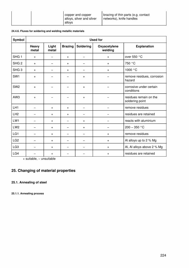
copper and copperalloys, silver and silveralloys
brazing of thin parts (e.g. contactnetworks), knife handles
24.4.6. Fluxes for soldering and welding metallic materials
Symbol Used for
Heavymetal
Lightmetal
Brazing Soldering Oxyacetylenewelding
Explanation
SHG 1 + − + − + over 550 °C
SHG 2 + − + − + 750 °C
SHG 3 + − + − + 1000 °C
SW1 + − − + − remove residues, corrosionhazard
SW2 + − − + − corrosive under certainconditions
AW3 + − − + − residues remain on thesoldering point
LH1 − + + − − remove residues
LH2 − + + − − residues are retained
LW1 − + − + − reacts with aluminium
LW2 − + − + − 200 − 350 °C
LG1 − + − − + remove residues
LG2 − + − − + Al alloys up to 2 % Mg
LG3 − + − − + Al, Al alloys above 2 % Mg
LG4 − + − − + residues are retained
+ suitable, − unsuitable
25. Changing of material properties
25.1. Annealing of steel
25.1.1. Annealing process
224

Long annealing times and high annealing temperatures result in macrostructures and should be avoided.
T Temperature, TG annealing temperature, t time,1 heating, 2 maintaining the annealing temperature, 3 cooling
Stress−free annealing 450 − 650 °C
Compensating of stresses after cold forming or after non−uniform cooling in heat treatment, hot forming orjoining.
Recrystallization annealing 650 − 750 °C
Removal of the disturbed structure after cold forming.
Soft annealing. Several hours at 710° C, several times for a short period at 723 °C.
Removal of hard spots in the structure after forging or casting; formation of a homogeneous soft structure forsubsequent metal cutting.
Normalizing 723 − 950 °C (depending on the C content)
Removal of the macrostructure after hot forming, casting or welding; increase in strength and toughness
25.1.2. Annealing temperatures and annealing colours
225

Temperature in °C Colour
1400
1300 white
1200 chrome yellow
1100 orange
1000 bright red
900 cherry−red
800 cherry−red (beginning)
700 dark red
600 dark red (beginning)
C content
1 Normalizing,2 recrystallization annealing,3 soft annealing,4 stress−free annealing
25.2. Hardening of steel
25.2.1. Hardening process
226

Heating of the steel (carbon content 0.4 − 1.5 %); rearrangement of the carbon particles; quenching (in wateror oil) results in a new, stressed structure; the workpieces become hard and brittle
T temperature, Tu transformation temperature (740 − 890 °C), t time 1 heating, 2 maintainingthe transformation temperature, 3 quenching
Normal hardening
Hardening effect throughout the workpiece (thin−walled workpieces)
Surface hardening
Hardening effect on the surface only; surface−hardened workpieces with a tough core
25.2.2. Quenchants
Quenchant Cooling rate (with reference to still air) Effect Use
Acidified water 35 very abrupt steel
0.5 − 0.9 %
Salty water 32 abrupt C−content
Water (20 °C) 30 vigorous
Milk of lime 24 less vigorous steel
0.9 − 1.5 %
Water (40 C) 22 almost mild C content
Petroleum 20 almost mild
Oil 14 mild steel
Compressed air 4 very mild alloyed
Still air 1 very mild
25.2.3. Quenching process
Shape ofworkpiece
Right Wrong
227
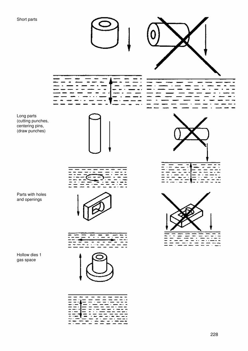
Short parts
Long parts(cutting punches,centering pins,(draw punches)
Parts with holesand openings
Hollow dies 1gas space
228
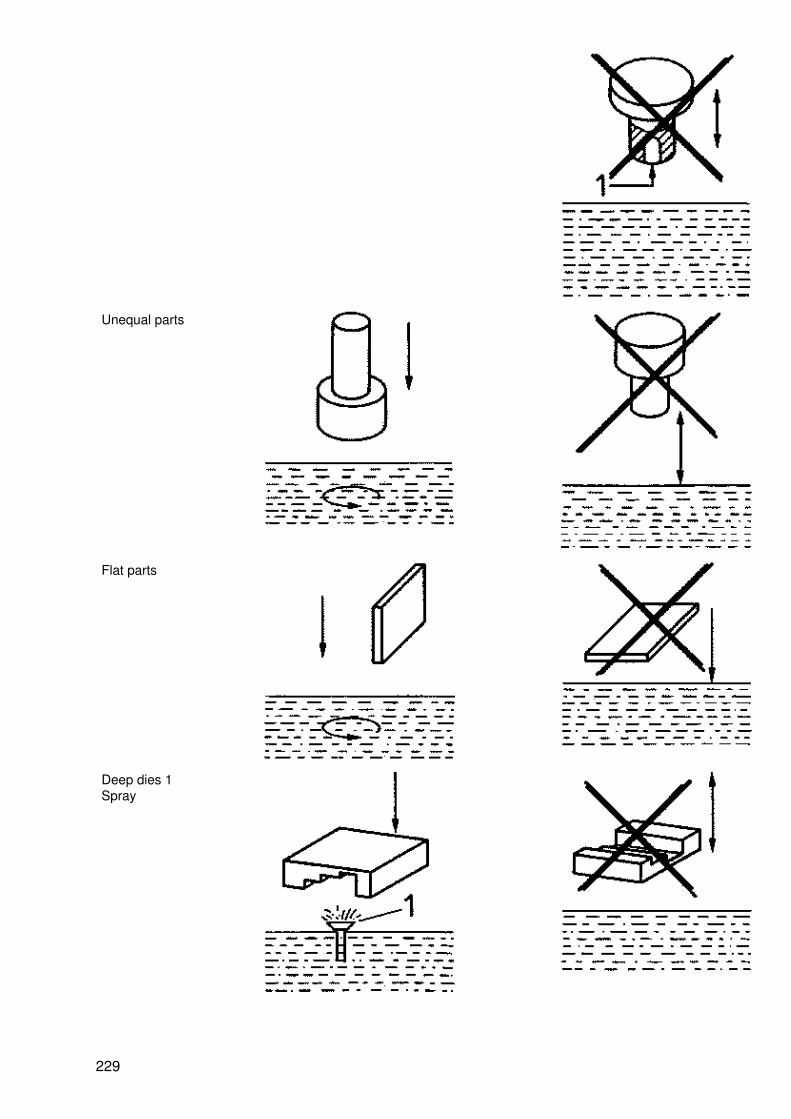
Unequal parts
Flat parts
Deep dies 1Spray
229

Chisels,centre−punches,piercers (quenchonly the cuttingedge)
25.2.4. Faults in hardening
Faults inhardening
Possible causes
Temperaturetoo low
Temperaturetoo high
Quenchanttoo abrupt
Quenchingtime too
short
Faultydipping
Drawingtemperature
too high
Insufficientmotion
Heatingtoo
rapid
Non−uniformheating
Drawingtemperature
too low
Quenchanttoo mild
Heatingtoo
long
too soft + + + +
non−uniformlyhard
+ + +
too hard + + +
brittle + +
Workpiecedistorted
+ + +
or ruptured + +
25.3. Tempering and hardening with subsequent drawing of steel
25.3.1. Tempering and hardening process
Tempering
Heating to Ta and quick cooling. Reduction in the hardness by quenching (glass hardness, brittleness).Adjustment of different hardness degrees, e.g. for tools
230
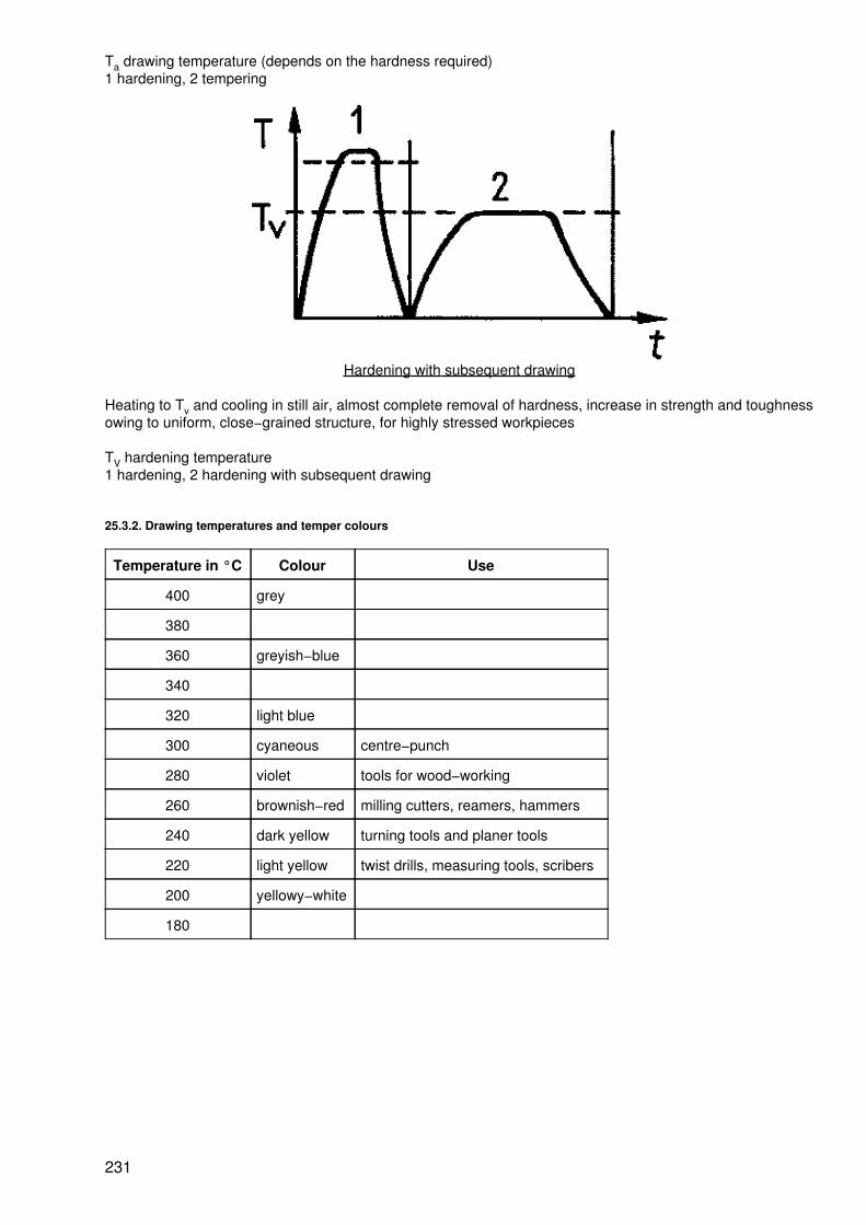
Ta drawing temperature (depends on the hardness required)1 hardening, 2 tempering
Hardening with subsequent drawing
Heating to Tv and cooling in still air, almost complete removal of hardness, increase in strength and toughnessowing to uniform, close−grained structure, for highly stressed workpieces
TV hardening temperature1 hardening, 2 hardening with subsequent drawing
25.3.2. Drawing temperatures and temper colours
Temperature in °C Colour Use
400 grey
380
360 greyish−blue
340
320 light blue
300 cyaneous centre−punch
280 violet tools for wood−working
260 brownish−red milling cutters, reamers, hammers
240 dark yellow turning tools and planer tools
220 light yellow twist drills, measuring tools, scribers
200 yellowy−white
180
231

232


