

The Company And The ProductsOEM Dynamics Pty Limited is a wholly Australian owned Company operating for over 25 years. The Company is a major supplier of fluid power related mechanical drives and accessories and industrial drives as well as being the industry leader in supply of oil heat transfer products for fluid power, gear and transmission oil cooling and compressor oil cooling through its DYNACOOL Division. The Company exports products to over 20 countries. OEM Dynamics has Quality Assurance accreditation to the requirements of AS3902/ISO9002. The assessor is Lloyds Register, certificate no. MEQ 0942414
About This CatalogueOur new catalogue PT5 supersedes the previous publications. The DYNAGEAR power transmission catalogues have become a popular reference in the fluid power, mobile/off road and diesel industry for hydraulic pump and diesel engine interfacing standards as well as a useful sourcing reference for drive components for these industries. The new PT5 publication continues in this tradition, but with a broader sourcing selection for general mobile/off road applications by inclusion of some new products and greater detail on existing products. With the exception of those items requiring assembly to customer specifications, most catalogue products are stock lines and can usually be shipped immediately.
The ProductsDYNAGEAR These products are Australian made and produced at our factory in Ballina NSW. They include a wide range of splined accessories, couplings, diesel drives, agricultural gearboxes, driveline components and overhung load adaptors.
FLEXILOCKAustralian designed and made, gear type polymer element shaft couplings for fluid power applications and direct hydraulic pump drive kits for diesel engines.
CLAMPLOCKAustralian designed and made, spline locking mechanisms which are incorporated in our gear type couplings, splined universal joint yokes and splined driveline companion flanges.
HUB CITYThe Hub City line is of US origin. Some of these products are assembled in Australia under licence they include a range of worm reduction gearboxes, right angle bevel gearboxes and agricultural accessories.
DURSTAnother of the Regal-Beloit US based companies which manufacture a range of high quality gear drives. OEM Dynamics assemble to order, from our Australian inventory, the new improved range of next generation hydraulic pump drive gearboxes for diesel engines.
TECHNODRIVEWe represent this well respected transmission manufacturer in Australia and South East Asia, with their range of Hydraulic pump drive gearboxes.
DYNACOOL Dynacool division is the largest supplier of air cooled heat exchangers for fluid power service in Australia. We have provided in this catalogue some selections of our range of air cooled mobile oil coolers. For full details on our heat transfer products please refer to DYNACOOL 220 for air cooled oil coolers and accessories.
AFTERMARKET SERVICESThis Division provides contract manufacturing facilities for aftermarket parts such as tractor and vehicle drivetrain components, shafts for pumps and complex 4 axis machined, drilled and milled items.
The Service OEM Dynamics prides itself on the ability to provide excellent customer service and rapid delivery of product. Our application engineers are highly experienced in providing technical advice in selection and the application of products. They have extensive training in mechanical interfacing, including hydraulic pump and motor attachments, spline identification, diesel engine housing and flywheel interfacing and the application of mechanical drives on mobile equipment in off road environments. The company maintains extensive inventory and customers can usually expect same day despatch of most items.
contents
3
Engine StandardsPage 4
Electric Motor StandardsPage 5
Splined ShaftPage 8
Stub WeldsPage 9
Round Bore HubsPage 11
Muff CouplingsPage 11
Splined YokesPage 16
Companion FlangesPage 16-17
HDC OHL AdaptorsPage 22
HH Dog ClutchPage 23
DZ Bevel Gear DrivesPage 36
Calculations & Useful FormulaPage 37
Pump Drive KitsPage 18-19
LPTO Drive KitsPage 20
LDA OHL AdaptorsPage 21
Flexilock CouplingsPage 12
Guardian CouplingsPage 14
Replacement ElementsPage 15
PTO AdaptorsPage 9
Stroke SegmentsPage 9
Slip SleevesPage 10
Splined HubsPage 6
T33 Pump DrivesPage 24-25
Splined CouplingsPage 7
H
J
7.9 (0.31") min axial andradial clearance for a mating
housing flange pilot
6.4 (0.25") min
Upper & lower tapped holesare rotated from vertical
8 bolt housings = 22.5 Deg12 bolt housings = 15 Deg
16 bolt housings = 11.25 Deg
Tapped holesequally spaced
FLYWHEEL
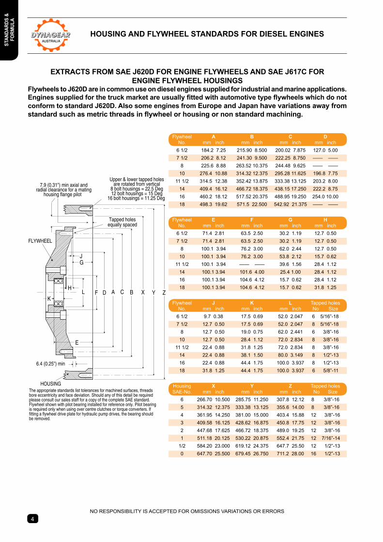
HOUSINGThe appropriate standards list tolerances for machined surfaces, threadsbore eccentricity and face deviation. Should any of this detail be requiredplease consult our sales staff for a copy of the complete SAE standard. Flywheel shown with pilot bearing installed for reference only. Pilot bearingis required only when using over centre clutches or torque converters. Iffitting a flywheel drive plate for hydraulic pump drives, the bearing shouldbe removed.
Bolt Hole
PL
Bolt Hole
A C BDF X Y ZLK
G
E
SL
S
PL
TL
PCD
P
P
PCD
TL
ND
Pump StandardsPage 5
H
J
7.9 (0.31") min axial andradial clearance for a mating
housing flange pilot
6.4 (0.25") min
Upper & lower tapped holesare rotated from vertical
8 bolt housings = 22.5 Deg12 bolt housings = 15 Deg
16 bolt housings = 11.25 Deg
Tapped holesequally spaced
FLYWHEEL
HOUSINGThe appropriate standards list tolerances for machined surfaces, threadsbore eccentricity and face deviation. Should any of this detail be requiredplease consult our sales staff for a copy of the complete SAE standard. Flywheel shown with pilot bearing installed for reference only. Pilot bearingis required only when using over centre clutches or torque converters. Iffitting a flywheel drive plate for hydraulic pump drives, the bearing shouldbe removed.
Bolt Hole
PL
Bolt Hole
A C BDF X Y ZLK
G
E
SL
S
PL
TL
PCD
P
P
PCD
TL
ND
Durst Pump DrivesPage 26-30
Technodrive Pump Drives
Page 31-32
Hub City BevelGear DrivesPage 33-34
AD Bevel Gear DrivesPage 35
Jan 2013
4
eXtRActs FRoM sAe J620D FoR enGIne FLYWHeeLs AnD sAe J617c FoRenGIne FLYWHeeL HoUsInGs
Flywheels to J620D are in common use on diesel engines supplied for industrial and marine applications. Engines supplied for the truck market are usually fitted with automotive type flywheels which do not conform to standard J620D. Also some engines from Europe and Japan have variations away from standard such as metric threads in flywheel or housing or non standard machining.
H
J
7.9 (0.31") min axial andradial clearance for a mating
housing flange pilot
6.4 (0.25") min
Upper & lower tapped holesare rotated from vertical
8 bolt housings = 22.5 Deg12 bolt housings = 15 Deg
16 bolt housings = 11.25 Deg
Tapped holesequally spaced
FLYWHEEL
HOUSINGThe appropriate standards list tolerances for machined surfaces, threadsbore eccentricity and face deviation. Should any of this detail be requiredplease consult our sales staff for a copy of the complete SAE standard. Flywheel shown with pilot bearing installed for reference only. Pilot bearingis required only when using over centre clutches or torque converters. Iffitting a flywheel drive plate for hydraulic pump drives, the bearing shouldbe removed.
Bolt Hole
PL
Bolt Hole
A C BDF X Y ZLK
G
E
SL
S
PL
TL
PCD
P
P
PCD
TL
ND
NO RESPONSIBILITY IS ACCEPTED FOR OMISSIONS VARIATIONS OR ERRORS
HoUsInG AnD FLYWHeeL stAnDARDs FoR DIeseL enGInes
Flywheel A B c D No. mm inch mm inch mm inch mm inch 6 1/2 184.2 7.25 215.90 8.500 200.02 7.875 127.0 5.00 7 1/2 206.2 8.12 241.30 9.500 222.25 8.750 —— —— 8 225.6 8.88 263.52 10.375 244.48 9.625 —— —— 10 276.4 10.88 314.32 12.375 295.28 11.625 196.8 7.75 11 1/2 314.5 12.38 352.42 13.875 333.38 13.125 203.2 8.00 14 409.4 16.12 466.72 18.375 438.15 17.250 222.2 8.75 16 460.2 18.12 517.52 20.375 488.95 19.250 254.0 10.00 18 498.3 19.62 571.5 22.500 542.92 21.375 —— ——
Flywheel e F G H No. mm inch mm inch mm inch mm inch 6 1/2 71.4 2.81 63.5 2.50 30.2 1.19 12.7 0.50 7 1/2 71.4 2.81 63.5 2.50 30.2 1.19 12.7 0.50 8 100.1 3.94 76.2 3.00 62.0 2.44 12.7 0.50 10 100.1 3.94 76.2 3.00 53.8 2.12 15.7 0.62 11 1/2 100.1 3.94 —— —— 39.6 1.56 28.4 1.12 14 100.1 3.94 101.6 4.00 25.4 1.00 28.4 1.12 16 100.1 3.94 104.6 4.12 15.7 0.62 28.4 1.12 18 100.1 3.94 104.6 4.12 15.7 0.62 31.8 1.25
Flywheel J K L Tapped holes No. mm inch mm inch mm inch No Size 6 1/2 9.7 0.38 17.5 0.69 52.0 2.047 6 5/16”-18 7 1/2 12.7 0.50 17.5 0.69 52.0 2.047 8 5/16”-18 8 12.7 0.50 19.0 0.75 62.0 2.441 6 3/8”-16 10 12.7 0.50 28.4 1.12 72.0 2.834 8 3/8”-16 11 1/2 22.4 0.88 31.8 1.25 72.0 2.834 8 3/8”-16 14 22.4 0.88 38.1 1.50 80.0 3.149 8 1/2”-13 16 22.4 0.88 44.4 1.75 100.0 3.937 8 1/2”-13 18 31.8 1.25 44.4 1.75 100.0 3.937 6 5/8”-11
Housing X Y Z Tapped holes SAE-No. mm inch mm inch mm inch No Size 6 266.70 10.500 285.75 11.250 307.8 12.12 8 3/8”-16 5 314.32 12.375 333.38 13.125 355.6 14.00 8 3/8”-16 4 361.95 14.250 381.00 15.000 403.4 15.88 12 3/8”-16 3 409.58 16.125 428.62 16.875 450.8 17.75 12 3/8”-16 2 447.68 17.625 466.72 18.375 489.0 19.25 12 3/8”-16 1 511.18 20.125 530.22 20.875 552.4 21.75 12 7/16”-14 1/2 584.20 23.000 619.12 24.375 647.7 25.50 12 1/2”-13 0 647.70 25.500 679.45 26.750 711.2 28.00 16 1/2”-13
stAnDARDs &FoRM
ULA
stAn
DARD
s &
FoRM
ULA
H
J
7.9 (0.31") min axial andradial clearance for a mating
housing flange pilot
6.4 (0.25") min
Upper & lower tapped holesare rotated from vertical
8 bolt housings = 22.5 Deg12 bolt housings = 15 Deg
16 bolt housings = 11.25 Deg
Tapped holesequally spaced
FLYWHEEL
HOUSINGThe appropriate standards list tolerances for machined surfaces, threadsbore eccentricity and face deviation. Should any of this detail be requiredplease consult our sales staff for a copy of the complete SAE standard. Flywheel shown with pilot bearing installed for reference only. Pilot bearingis required only when using over centre clutches or torque converters. Iffitting a flywheel drive plate for hydraulic pump drives, the bearing shouldbe removed.
Bolt Hole
PL
Bolt Hole
A C BDF X Y ZLK
G
E
SL
S
PL
TL
PCD
P
P
PCD
TL
ND
5
HYDRAULIc PUMP & MotoR MoUnt FLAnGe & sHAFt InDUstRY stAnDARDs
H
J
7.9 (0.31") min axial andradial clearance for a mating
housing flange pilot
6.4 (0.25") min
Upper & lower tapped holesare rotated from vertical
8 bolt housings = 22.5 Deg12 bolt housings = 15 Deg
16 bolt housings = 11.25 Deg
Tapped holesequally spaced
FLYWHEEL
HOUSINGThe appropriate standards list tolerances for machined surfaces, threadsbore eccentricity and face deviation. Should any of this detail be requiredplease consult our sales staff for a copy of the complete SAE standard. Flywheel shown with pilot bearing installed for reference only. Pilot bearingis required only when using over centre clutches or torque converters. Iffitting a flywheel drive plate for hydraulic pump drives, the bearing shouldbe removed.
Bolt Hole
PL
Bolt Hole
A C BDF X Y ZLK
G
E
SL
S
PL
TL
PCD
P
P
PCD
TL
ND
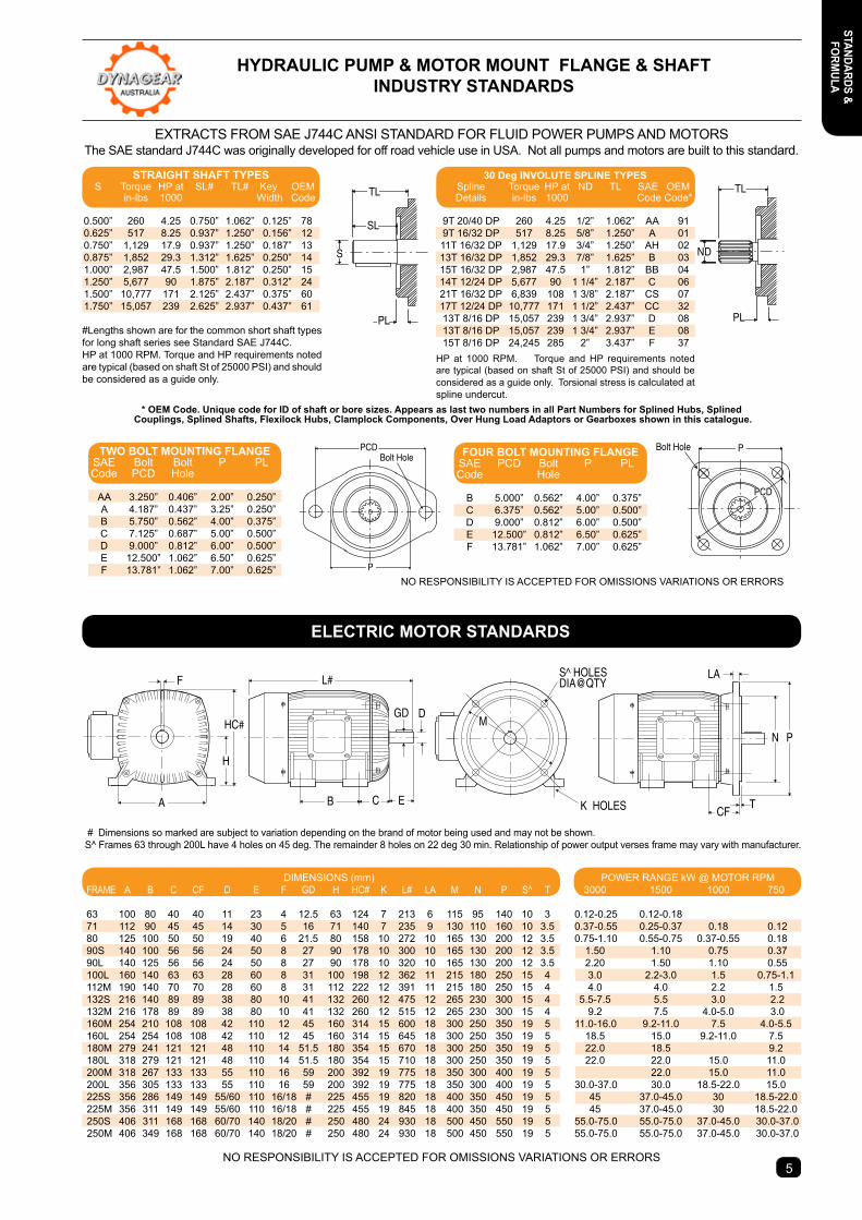
EXTRACTS FROM SAE J744C ANSI STANDARD FOR FLUID POWER PUMPS AND MOTORSThe SAE standard J744C was originally developed for off road vehicle use in USA. Not all pumps and motors are built to this standard.
* oeM code. Unique code for ID of shaft or bore sizes. Appears as last two numbers in all Part numbers for splined Hubs, splined Couplings, Splined Shafts, Flexilock Hubs, Clamplock Components, Over Hung Load Adaptors or Gearboxes shown in this catalogue.
NO RESPONSIBILITY IS ACCEPTED FOR OMISSIONS VARIATIONS OR ERRORS
#Lengths shown are for the common short shaft types for long shaft series see Standard SAE J744C. HP at 1000 RPM. Torque and HP requirements noted are typical (based on shaft St of 25000 PSI) and should be considered as a guide only.
HP at 1000 RPM. Torque and HP requirements noted are typical (based on shaft St of 25000 PSI) and should be considered as a guide only. Torsional stress is calculated at spline undercut.
H
J
7.9 (0.31") min axial andradial clearance for a mating
housing flange pilot
6.4 (0.25") min
Upper & lower tapped holesare rotated from vertical
8 bolt housings = 22.5 Deg12 bolt housings = 15 Deg
16 bolt housings = 11.25 Deg
Tapped holesequally spaced
FLYWHEEL
HOUSINGThe appropriate standards list tolerances for machined surfaces, threadsbore eccentricity and face deviation. Should any of this detail be requiredplease consult our sales staff for a copy of the complete SAE standard. Flywheel shown with pilot bearing installed for reference only. Pilot bearingis required only when using over centre clutches or torque converters. Iffitting a flywheel drive plate for hydraulic pump drives, the bearing shouldbe removed.
Bolt Hole
PL
Bolt Hole
A C BDF X Y ZLK
G
E
SL
S
PL
TL
PCD
P
P
PCD
TL
ND
S^ HOLESDIA@QTY
K HOLES
F
D GD
T
LA
CF
PN
L#
B C EA
HC#
H
M
# Dimensions so marked are subject to variation depending on the brand of motor being used and may not be shown. S^ Frames 63 through 200L have 4 holes on 45 deg. The remainder 8 holes on 22 deg 30 min. Relationship of power output verses frame may vary with manufacturer.
NO RESPONSIBILITY IS ACCEPTED FOR OMISSIONS VARIATIONS OR ERRORS
DIMENSIONS (mm) FRAME A B C CF D E F GD H HC# K L# LA M N P S^ T 63 100 80 40 40 11 23 4 12.5 63 124 7 213 6 115 95 140 10 3 71 112 90 45 45 14 30 5 16 71 140 7 235 9 130 110 160 10 3.5 80 125 100 50 50 19 40 6 21.5 80 158 10 272 10 165 130 200 12 3.5 90S 140 100 56 56 24 50 8 27 90 178 10 300 10 165 130 200 12 3.5 90L 140 125 56 56 24 50 8 27 90 178 10 320 10 165 130 200 12 3.5 100L 160 140 63 63 28 60 8 31 100 198 12 362 11 215 180 250 15 4 112M 190 140 70 70 28 60 8 31 112 222 12 391 11 215 180 250 15 4 132S 216 140 89 89 38 80 10 41 132 260 12 475 12 265 230 300 15 4 132M 216 178 89 89 38 80 10 41 132 260 12 515 12 265 230 300 15 4 160M 254 210 108 108 42 110 12 45 160 314 15 600 18 300 250 350 19 5 160L 254 254 108 108 42 110 12 45 160 314 15 645 18 300 250 350 19 5 180M 279 241 121 121 48 110 14 51.5 180 354 15 670 18 300 250 350 19 5 180L 318 279 121 121 48 110 14 51.5 180 354 15 710 18 300 250 350 19 5 200M 318 267 133 133 55 110 16 59 200 392 19 775 18 350 300 400 19 5 200L 356 305 133 133 55 110 16 59 200 392 19 775 18 350 300 400 19 5 225S 356 286 149 149 55/60 110 16/18 # 225 455 19 820 18 400 350 450 19 5 225M 356 311 149 149 55/60 110 16/18 # 225 455 19 845 18 400 350 450 19 5 250S 406 311 168 168 60/70 140 18/20 # 250 480 24 930 18 500 450 550 19 5 250M 406 349 168 168 60/70 140 18/20 # 250 480 24 930 18 500 450 550 19 5
POWER RANGE kW @ MOTOR RPM 3000 1500 1000 750
0.12-0.25 0.12-0.18 0.37-0.55 0.25-0.37 0.18 0.12 0.75-1.10 0.55-0.75 0.37-0.55 0.18 1.50 1.10 0.75 0.37 2.20 1.50 1.10 0.55 3.0 2.2-3.0 1.5 0.75-1.1 4.0 4.0 2.2 1.5 5.5-7.5 5.5 3.0 2.2 9.2 7.5 4.0-5.0 3.0 11.0-16.0 9.2-11.0 7.5 4.0-5.5 18.5 15.0 9.2-11.0 7.5 22.0 18.5 9.2 22.0 22.0 15.0 11.0 22.0 15.0 11.0 30.0-37.0 30.0 18.5-22.0 15.0 45 37.0-45.0 30 18.5-22.0 45 37.0-45.0 30 18.5-22.0 55.0-75.0 55.0-75.0 37.0-45.0 30.0-37.0 55.0-75.0 55.0-75.0 37.0-45.0 30.0-37.0
30 Deg InVoLUte sPLIne tYPes Spline Torque HP at ND TL SAE OEM Details in-lbs 1000 Code Code*
9T 20/40 DP 260 4.25 1/2” 1.062” AA 91 9T 16/32 DP 517 8.25 5/8” 1.250” A 01 11T 16/32 DP 1,129 17.9 3/4” 1.250” AH 02 13T 16/32 DP 1,852 29.3 7/8” 1.625” B 03 15T 16/32 DP 2,987 47.5 1” 1.812” BB 04 14T 12/24 DP 5,677 90 1 1/4” 2.187” C 06 21T 16/32 DP 6,839 108 1 3/8” 2.187” CS 07 17T 12/24 DP 10,777 171 1 1/2” 2.437” CC 32 13T 8/16 DP 15,057 239 1 3/4” 2.937” D 08 13T 8/16 DP 15,057 239 1 3/4” 2.937” E 08 15T 8/16 DP 24,245 285 2” 3.437” F 37
stRAIGHt sHAFt tYPes S Torque HP at SL# TL# Key OEM in-lbs 1000 Width Code
0.500” 260 4.25 0.750” 1.062” 0.125” 78 0.625” 517 8.25 0.937” 1.250” 0.156” 12 0.750” 1,129 17.9 0.937” 1.250” 0.187” 13 0.875” 1,852 29.3 1.312” 1.625” 0.250” 14 1.000” 2,987 47.5 1.500” 1.812” 0.250” 15 1.250” 5,677 90 1.875” 2.187” 0.312” 24 1.500” 10,777 171 2.125” 2.437” 0.375” 60 1.750” 15,057 239 2.625” 2.937” 0.437” 61
tWo BoLt MoUntInG FLAnGe SAE Bolt Bolt P PL Code PCD Hole
AA 3.250” 0.406” 2.00” 0.250” A 4.187” 0.437” 3.25” 0.250” B 5.750” 0.562” 4.00” 0.375” C 7.125” 0.687” 5.00” 0.500” D 9.000” 0.812” 6.00” 0.500” E 12.500” 1.062” 6.50” 0.625” F 13.781” 1.062” 7.00” 0.625”
FoUR BoLt MoUntInG FLAnGe SAE PCD Bolt P PL Code Hole
B 5.000” 0.562” 4.00” 0.375” C 6.375” 0.562” 5.00” 0.500” D 9.000” 0.812” 6.00” 0.500” E 12.500” 0.812” 6.50” 0.625” F 13.781” 1.062” 7.00” 0.625”
eLectRIc MotoR stAnDARDs
stAnDARDs &FoRM
ULA
stAn
DARD
s &
FoRM
ULA
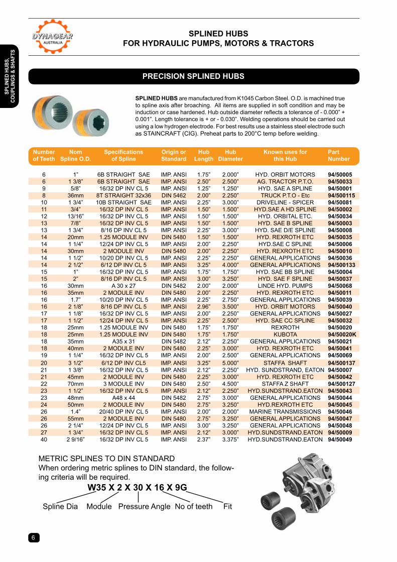
PRecIsIon sPLIneD HUBs
sPLIneD HUBsFoR HYDRAULIc PUMPs, MotoRs & tRActoRs
sPLIneD HUBs are manufactured from K1045 Carbon Steel. O.D. is machined true to spline axis after broaching. All items are supplied in soft condition and may be induction or case hardened. Hub outside diameter reflects a tolerance of - 0.000” + 0.001”. Length tolerance is + or - 0.030”. Welding operations should be carried out using a low hydrogen electrode. For best results use a stainless steel electrode such as STAINCRAFT (CIG). Preheat parts to 200°C temp before welding.
METRIC SPLINES TO DIN STANDARDWhen ordering metric splines to DIN standard, the follow-ing criteria will be required.
W35 X 2 X 30 X 16 X 9G
Spline Dia Module Pressure Angle No of teeth Fit
6
Number Nom Specifications Origin or Hub Hub Known uses for Part of teeth spline o.D. of spline standard Length Diameter this Hub number
6 1” 6B STRAIGHT SAE IMP. ANSI 1.75” 2.000” HYD. ORBIT MOTORS 94/50005 6 1 3/8” 6B STRAIGHT SAE IMP. ANSI 2.50” 2.500” AG. TRACTOR P.T.O. 94/50033 9 5/8” 16/32 DP INV CL 5 IMP. ANSI 1.25” 1.250” HYD. SAE A SPLINE 94/50001 8 36mm 8T STRAIGHT 32x36 DIN 5462 2.00” 2.250” TRUCK P.T.O - Etc 94/500115 10 1 3/4” 10B STRAIGHT SAE IMP. ANSI 2.25” 3.000” DRIVELINE - SPICER 94/50081 11 3/4” 16/32 DP INV CL 5 IMP. ANSI 1.50” 1.500” HYD.SAE A HD SPLINE 94/50002 12 13/16” 16/32 DP INV CL 5 IMP. ANSI 1.50” 1.500” HYD. ORBITAL ETC. 94/50034 13 7/8” 16/32 DP INV CL 5 IMP. ANSI 1.50” 1.500” HYD. SAE B SPLINE 94/50003 13 1 3/4” 8/16 DP INV CL 5 IMP. ANSI 2.25” 3.000” HYD. SAE D/E SPLINE 94/50008 14 20mm 1.25 MODULE INV DIN 5480 1.50” 1.500” HYD. REXROTH ETC 94/50035 14 1 1/4” 12/24 DP INV CL 5 IMP. ANSI 2.00” 2.250” HYD.SAE C SPLINE 94/50006 14 30mm 2 MODULE INV DIN 5480 2.00” 2.250” HYD. REXROTH ETC 94/50010 14 1 1/2” 10/20 DP INV CL 5 IMP. ANSI 2.25” 2.250” GENERAL APPLICATIONS 94/50036 14 2 1/2” 6/12 DP INV CL 5 IMP. ANSI 3.25” 4.000” GENERAL APPLICATIONS 94/500133 15 1” 16/32 DP INV CL 5 IMP. ANSI 1.75” 1.750” HYD. SAE BB SPLINE 94/50004 15 2” 8/16 DP INV CL 5 IMP. ANSI 3.00” 3.250” HYD. SAE F SPLINE 94/50037 16 30mm A 30 x 27 DIN 5482 2.00” 2.000” LINDE HYD. PUMPS 94/50068 16 35mm 2 MODULE INV DIN 5480 2.00” 2.250” HYD. REXROTH ETC 94/50011 16 1.7” 10/20 DP INV CL 5 IMP. ANSI 2.25” 2.750” GENERAL APPLICATIONS 94/50039 16 2 1/8” 8/16 DP INV CL 5 IMP. ANSI 2.96” 3.500” HYD. ORBIT MOTORS 94/50040 17 1 1/8” 16/32 DP INV CL 5 IMP. ANSI 2.00” 2.250” GENERAL APPLICATIONS 94/50027 17 1 1/2” 12/24 DP INV CL 5 IMP. ANSI 2.25” 2.500” HYD. SAE CC SPLINE 94/50032 18 25mm 1.25 MODULE INV DIN 5480 1.75” 1.750” REXROTH 94/50020 18 25mm 1.25 MODULE INV DIN 5480 1.75” 1.750” KUBOTA 94/50020K 18 35mm A35 x 31 DIN 5482 2.12” 2.250” GENERAL APPLICATIONS 94/50021 18 40mm 2 MODULE INV DIN 5480 2.25” 3.000” HYD. REXROTH ETC 94/50041 19 1 1/4” 16/32 DP INV CL 5 IMP. ANSI 2.00” 2.500” GENERAL APPLICATIONS 94/50069 20 3 1/2” 6/12 DP INV CL5 IMP. ANSI 3.25” 5.000” STAFFA SHAFT 94/500137 21 1 3/8” 16/32 DP INV CL 5 IMP. ANSI 2.12” 2.250” HYD. SUNDSTRAND, EATON 94/50007 21 45mm 2 MODULE INV DIN 5480 2.25” 3.000” HYD. REXROTH ETC 94/50042 22 70mm 3 MODULE INV DIN 5480 2.50” 4.500” STAFFA Z SHAFT 94/500127 23 1 1/2” 16/32 DP INV CL 5 IMP. ANSI 2.12” 2.250” HYD.SUNDSTRAND.EATON 94/50043 23 48mm A48 x 44 DIN 5482 2.75” 3.000” GENERAL APPLICATIONS 94/50044 24 50mm 2 MODULE INV DIN 5480 2.75” 3.250” HYD.REXROTH ETC 94/50045 26 1.4” 20/40 DP INV CL 5 IMP. ANSI 2.00” 2.000” MARINE TRANSMISSIONS 94/50046 26 55mm 2 MODULE INV DIN 5480 2.75” 3.250” GENERAL APPLICATIONS 94/50047 26 2 1/4” 12/24 DP INV CL 5 IMP. ANSI 3.00” 3.250” GENERAL APPLICATIONS 94/50048 27 1 3/4” 16/32 DP INV CL 5 IMP. ANSI 2.12” 3.000” HYD.SUNDSTRAND.EATON 94/50009 40 2 9/16” 16/32 DP INV CL 5 IMP. ANSI 2.37” 3.375” HYD.SUNDSTRAND.EATON 94/50049
sPLI
neD
HUBs
, co
UPLI
nGs
& sH
AFts
7
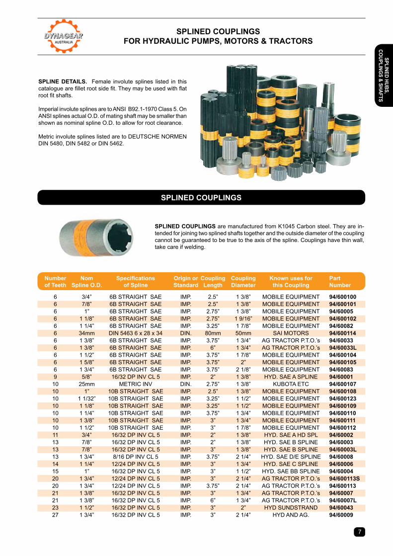
sPLIneD coUPLInGsFoR HYDRAULIc PUMPs, MotoRs & tRActoRs
sPLIneD coUPLInGs are manufactured from K1045 Carbon steel. They are in-tended for joining two splined shafts together and the outside diameter of the coupling cannot be guaranteed to be true to the axis of the spline. Couplings have thin wall, take care if welding.
sPLIne DetAILs. Female involute splines listed in this catalogue are fillet root side fit. They may be used with flat root fit shafts.
Imperial involute splines are to ANSI B92.1-1970 Class 5. On ANSI splines actual O.D. of mating shaft may be smaller than shown as nominal spline O.D. to allow for root clearance.
Metric involute splines listed are to DEUTSCHE NORMEN DIN 5480, DIN 5482 or DIN 5462.
sPLIneD coUPLInGs
Number Nom Specifications Origin or Coupling Coupling Known uses for Part of teeth spline o.D. of spline standard Length Diameter this coupling number
6 3/4” 6B STRAIGHT SAE IMP. 2.5” 1 3/8” MOBILE EQUIPMENT 94/600100 6 7/8” 6B STRAIGHT SAE IMP. 2.5” 1 3/8” MOBILE EQUIPMENT 94/600101 6 1” 6B STRAIGHT SAE IMP. 2.75” 1 3/8” MOBILE EQUIPMENT 94/60005 6 1 1/8” 6B STRAIGHT SAE IMP. 2.75” 1 9/16” MOBILE EQUIPMENT 94/600102 6 1 1/4” 6B STRAIGHT SAE IMP. 3.25” 1 7/8” MOBILE EQUIPMENT 94/60082 6 34mm DIN 5463 6 x 28 x 34 DIN. 80mm 50mm SAI MOTORS 94/600114 6 1 3/8” 6B STRAIGHT SAE IMP. 3.75” 1 3/4” AG TRACTOR P.T.O.’s 94/60033 6 1 3/8” 6B STRAIGHT SAE IMP. 6” 1 3/4” AG TRACTOR P.T.O.’s 94/60033L 6 1 1/2” 6B STRAIGHT SAE IMP. 3.75” 1 7/8” MOBILE EQUIPMENT 94/600104 6 1 5/8” 6B STRAIGHT SAE IMP. 3.75” 2” MOBILE EQUIPMENT 94/600105 6 1 3/4” 6B STRAIGHT SAE IMP. 3.75” 2 1/8” MOBILE EQUIPMENT 94/60083 9 5/8” 16/32 DP INV CL 5 IMP. 2” 1 3/8” HYD. SAE A SPLINE 94/60001 10 25mm METRIC INV DIN. 2.75” 1 3/8” KUBOTA ETC 94/600107 10 1” 10B STRAIGHT SAE IMP. 2.5” 1 3/8” MOBILE EQUIPMENT 94/600108 10 1 1/32” 10B STRAIGHT SAE IMP. 3.25” 1 1/2” MOBILE EQUIPMENT 94/600123 10 1 1/8” 10B STRAIGHT SAE IMP. 3.25” 1 1/2” MOBILE EQUIPMENT 94/600109 10 1 1/4” 10B STRAIGHT SAE IMP. 3.75” 1 3/4” MOBILE EQUIPMENT 94/600110 10 1 3/8” 10B STRAIGHT SAE IMP. 3” 1 3/4” MOBILE EQUIPMENT 94/600111 10 1 1/2” 10B STRAIGHT SAE IMP. 3” 1 7/8” MOBILE EQUIPMENT 94/600112 11 3/4” 16/32 DP INV CL 5 IMP. 2” 1 3/8” HYD. SAE A HD SPL 94/60002 13 7/8” 16/32 DP INV CL 5 IMP. 2” 1 3/8” HYD. SAE B SPLINE 94/60003 13 7/8” 16/32 DP INV CL 5 IMP. 3” 1 3/8” HYD. SAE B SPLINE 94/60003L 13 1 3/4” 8/16 DP INV CL 5 IMP. 3.75” 2 1/4” HYD. SAE D/E SPLINE 94/60008 14 1 1/4” 12/24 DP INV CL 5 IMP. 3” 1 3/4” HYD. SAE C SPLINE 94/60006 15 1” 16/32 DP INV CL 5 IMP. 3” 1 1/2” HYD. SAE BB SPLINE 94/60004 20 1 3/4” 12/24 DP INV CL 5 IMP. 3” 2 1/4” AG TRACTOR P.T.O.’s 94/600113s 20 1 3/4” 12/24 DP INV CL 5 IMP. 3.75” 2 1/4” AG TRACTOR P.T.O.’s 94/600113 21 1 3/8” 16/32 DP INV CL 5 IMP. 3” 1 3/4” AG TRACTOR P.T.O.’s 94/60007 21 1 3/8” 16/32 DP INV CL 5 IMP. 6” 1 3/4” AG TRACTOR P.T.O.’s 94/60007L 23 1 1/2” 16/32 DP INV CL 5 IMP. 3” 2” HYD SUNDSTRAND 94/60043 27 1 3/4” 16/32 DP INV CL 5 IMP. 3” 2 1/4” HYD AND AG. 94/60009
sPLIneD HUBs, coUPLInGs & sHAFts
57/03/016200.622" 0.624"57/03/016220.997" 0.999"
BA SHAFT END
DIA"E"
D
C
E
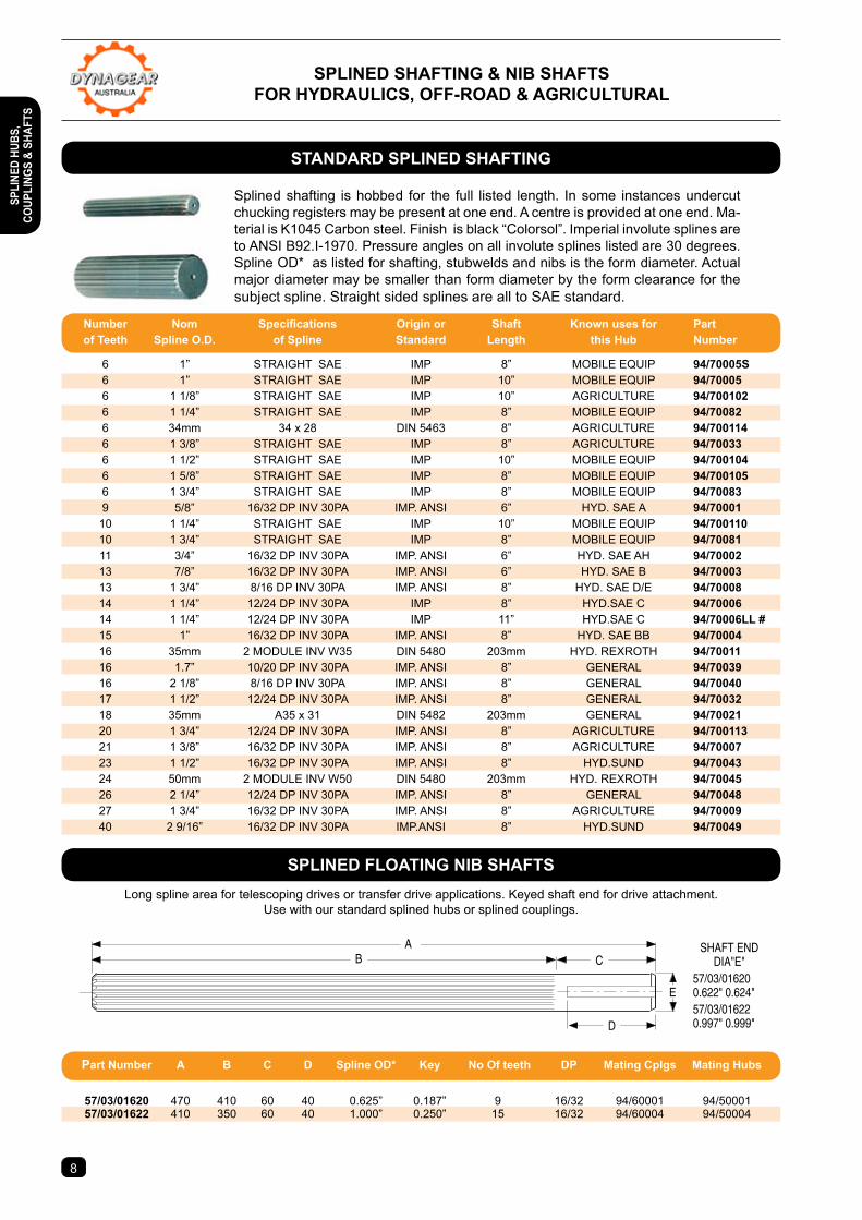
Splined shafting is hobbed for the full listed length. In some instances undercut chucking registers may be present at one end. A centre is provided at one end. Ma-terial is K1045 Carbon steel. Finish is black “Colorsol”. Imperial involute splines are to ANSI B92.I-1970. Pressure angles on all involute splines listed are 30 degrees. Spline OD* as listed for shafting, stubwelds and nibs is the form diameter. Actual major diameter may be smaller than form diameter by the form clearance for the subject spline. Straight sided splines are all to SAE standard.
Long spline area for telescoping drives or transfer drive applications. Keyed shaft end for drive attachment.Use with our standard splined hubs or splined couplings.
sPLIneD sHAFtInG & nIB sHAFtsFoR HYDRAULIcs, oFF-RoAD & AGRIcULtURAL
8
stAnDARD sPLIneD sHAFtInG
sPLIneD FLoAtInG nIB sHAFts
Number Nom Specifications Origin or Shaft Known uses for Part of teeth spline o.D. of spline standard Length this Hub number
6 1” STRAIGHT SAE IMP 8” MOBILE EQUIP 94/70005s 6 1” STRAIGHT SAE IMP 10” MOBILE EQUIP 94/70005 6 1 1/8” STRAIGHT SAE IMP 10” AGRICULTURE 94/700102 6 1 1/4” STRAIGHT SAE IMP 8” MOBILE EQUIP 94/70082 6 34mm 34 x 28 DIN 5463 8” AGRICULTURE 94/700114 6 1 3/8” STRAIGHT SAE IMP 8” AGRICULTURE 94/70033 6 1 1/2” STRAIGHT SAE IMP 10” MOBILE EQUIP 94/700104 6 1 5/8” STRAIGHT SAE IMP 8” MOBILE EQUIP 94/700105 6 1 3/4” STRAIGHT SAE IMP 8” MOBILE EQUIP 94/70083 9 5/8” 16/32 DP INV 30PA IMP. ANSI 6” HYD. SAE A 94/70001 10 1 1/4” STRAIGHT SAE IMP 10” MOBILE EQUIP 94/700110 10 1 3/4” STRAIGHT SAE IMP 8” MOBILE EQUIP 94/70081 11 3/4” 16/32 DP INV 30PA IMP. ANSI 6” HYD. SAE AH 94/70002 13 7/8” 16/32 DP INV 30PA IMP. ANSI 6” HYD. SAE B 94/70003 13 1 3/4” 8/16 DP INV 30PA IMP. ANSI 8” HYD. SAE D/E 94/70008 14 1 1/4” 12/24 DP INV 30PA IMP 8” HYD.SAE C 94/70006 14 1 1/4” 12/24 DP INV 30PA IMP 11” HYD.SAE C 94/70006LL # 15 1” 16/32 DP INV 30PA IMP. ANSI 8” HYD. SAE BB 94/70004 16 35mm 2 MODULE INV W35 DIN 5480 203mm HYD. REXROTH 94/70011 16 1.7” 10/20 DP INV 30PA IMP. ANSI 8” GENERAL 94/70039 16 2 1/8” 8/16 DP INV 30PA IMP. ANSI 8” GENERAL 94/70040 17 1 1/2” 12/24 DP INV 30PA IMP. ANSI 8” GENERAL 94/70032 18 35mm A35 x 31 DIN 5482 203mm GENERAL 94/70021 20 1 3/4” 12/24 DP INV 30PA IMP. ANSI 8” AGRICULTURE 94/700113 21 1 3/8” 16/32 DP INV 30PA IMP. ANSI 8” AGRICULTURE 94/70007 23 1 1/2” 16/32 DP INV 30PA IMP. ANSI 8” HYD.SUND 94/70043 24 50mm 2 MODULE INV W50 DIN 5480 203mm HYD. REXROTH 94/70045 26 2 1/4” 12/24 DP INV 30PA IMP. ANSI 8” GENERAL 94/70048 27 1 3/4” 16/32 DP INV 30PA IMP. ANSI 8” AGRICULTURE 94/70009 40 2 9/16” 16/32 DP INV 30PA IMP.ANSI 8” HYD.SUND 94/70049
Part number A B c D spline oD* Key no of teeth DP Mating cplgs Mating Hubs
57/03/01620 470 410 60 40 0.625” 0.187” 9 16/32 94/60001 94/50001 57/03/01622 410 350 60 40 1.000” 0.250” 15 16/32 94/60004 94/50004
sPLI
neD
HUBs
, co
UPLI
nGs
& sH
AFts
9
M & F SPLINED COUPLING
Splined HubStubweld
Weld
SPLINED SHAFT END
ShaftStubweld
Weld
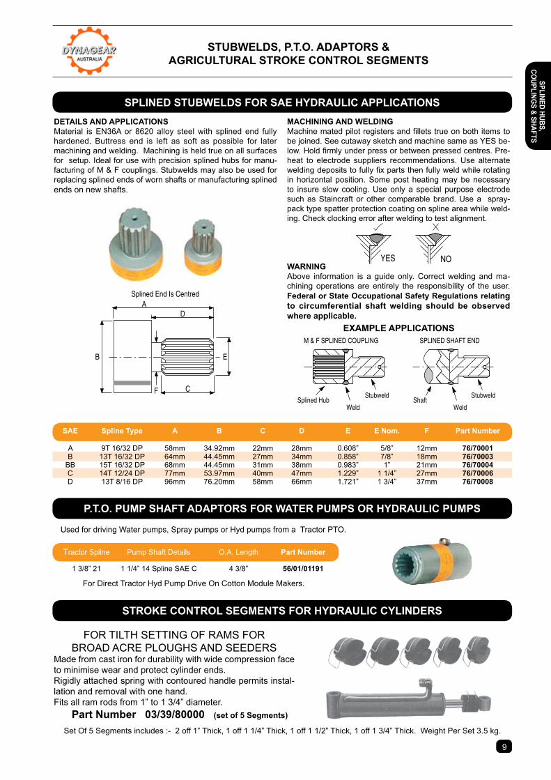
DetAILs AnD APPLIcAtIonsMaterial is EN36A or 8620 alloy steel with splined end fully hardened. Buttress end is left as soft as possible for later machining and welding. Machining is held true on all surfaces for setup. Ideal for use with precision splined hubs for manu-facturing of M & F couplings. Stubwelds may also be used for replacing splined ends of worn shafts or manufacturing splined ends on new shafts.
MAcHInInG AnD WeLDInGMachine mated pilot registers and fillets true on both items to be joined. See cutaway sketch and machine same as YES be-low. Hold firmly under press or between pressed centres. Pre-heat to electrode suppliers recommendations. Use alternate welding deposits to fully fix parts then fully weld while rotating in horizontal position. Some post heating may be necessary to insure slow cooling. Use only a special purpose electrode such as Staincraft or other comparable brand. Use a spray-pack type spatter protection coating on spline area while weld-ing. Check clocking error after welding to test alignment.
WARnInGAbove information is a guide only. Correct welding and ma-chining operations are entirely the responsibility of the user. Federal or state occupational safety Regulations relating to circumferential shaft welding should be observed where applicable.
NOYES
eXAMPLe APPLIcAtIons
A
B
C
E
D
F
Splined End Is Centred
FOR TILTH SETTING OF RAMS FORBROAD ACRE PLOUGHS AND SEEDERS
Made from cast iron for durability with wide compression face to minimise wear and protect cylinder ends.Rigidly attached spring with contoured handle permits instal-lation and removal with one hand.Fits all ram rods from 1” to 1 3/4” diameter. Part number 03/39/80000 (set of 5 segments)
Set Of 5 Segments includes :- 2 off 1” Thick, 1 off 1 1/4” Thick, 1 off 1 1/2” Thick, 1 off 1 3/4” Thick. Weight Per Set 3.5 kg.
Used for driving Water pumps, Spray pumps or Hyd pumps from a Tractor PTO.
For Direct Tractor Hyd Pump Drive On Cotton Module Makers.
stUBWeLDs, P.t.o. ADAPtoRs &AGRIcULtURAL stRoKe contRoL seGMents
sPLIneD stUBWeLDs FoR sAe HYDRAULIc APPLIcAtIons
P.t.o. PUMP sHAFt ADAPtoRs FoR WAteR PUMPs oR HYDRAULIc PUMPs
stRoKe contRoL seGMents FoR HYDRAULIc cYLInDeRs
sAe spline type A B c D e e nom. F Part number
A 9T 16/32 DP 58mm 34.92mm 22mm 28mm 0.608” 5/8” 12mm 76/70001 B 13T 16/32 DP 64mm 44.45mm 27mm 34mm 0.858” 7/8” 18mm 76/70003 BB 15T 16/32 DP 68mm 44.45mm 31mm 38mm 0.983” 1” 21mm 76/70004 C 14T 12/24 DP 77mm 53.97mm 40mm 47mm 1.229” 1 1/4” 27mm 76/70006 D 13T 8/16 DP 96mm 76.20mm 58mm 66mm 1.721” 1 3/4” 37mm 76/70008
Tractor Spline Pump Shaft Details O.A. Length Part number
1 3/8” 21 1 1/4” 14 Spline SAE C 4 3/8” 56/01/01191
sPLIneD HUBs, coUPLInGs & sHAFts
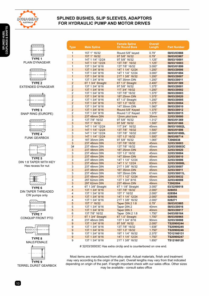
sPLIneD BUsHes, sLIP sLeeVes, ADAPtoRs FoR HYDRAULIc PUMP AnD MotoR DRIVes
tYPe 3SNAP RING (EUROPE)
tYPe 4FUNK GEARBOX
tYPe 5DIN 1:8 TAPER WITH KEY
Has recess for nut
tYPe 6DIN TAPER THREADED
CW pumps only
tYPe 7CONQUIP FRONT PTO
tYPe 8MALE/FEMALE
tYPe 1PLAIN DYNAGEAR
tYPe 2EXTENDED DYNAGEAR
tYPe 9TERREL DURST GEARBOX
Most items are manufactured from alloy steel. Actual materials, finish and treatment may vary according to the origin of the part. Overall lengths may vary from that indicated
depending on origin of the part. If length important check with our sales office. Other sizes may be available - consult sales office
1110
# 32/03/30003C Has extra circlip and is counterbored on one end.
Female Spline Overall type Male spline or Round Bore Length Part number
1 15T 1” 16/32 Round 5/8” keyed 0.79” 58/03/03988 1 15T 1” 16/32 9T 5/8” 16/32 0.79” 58/03/03987 1 14T 1 1/4” 12/24 9T 5/8” 16/32 1.125” 58/03/10001 1 14T 1 1/4” 12/24 13T 7/8” 16/32 1.125” 58/03/10003 1 13T 1 3/4” 8/16 13T 7/8” 16/32 3.000” 58/03/01899 1 13T 1 3/4” 8/16 14T 1 1/4” 12/24 1.200” 58/03/20006 1 13T 1 3/4” 8/16 14T 1 1/4” 12/24 3.000” 58/03/01694 1 13T 1 3/4” 8/16 21T 1 3/8” 16/32 1.200” 58/03/20007 1 13T 1 3/4” 8/16 16T 35mm DIN 1.200” 58/03/20011 2 6T 1 3/4” Straight 6T 1.0” Straight 2.400” 58/03/01589 2 13T 1 3/4” 8/16 9T 5/8” 16/32 1.375” 58/03/20001 2 13T 1 3/4” 8/16 11T 3/4” 16/32 1.200” 58/03/20002 2 13T 1 3/4” 8/16 13T 7/8” 16/32 1.375” 58/03/20003 2 13T 1 3/4” 8/16 18T 25mm DIN 1.375” 58/03/20020 2 13T 1 3/4” 8/16 6T 1.0” Straight 1.200” 58/03/20005 2 13T 1 3/4” 8/16 15T 1.0” 16/32 1.375” 58/03/20004 2 13T 1 3/4” 8/16 14T 30mm DIN 1.560” 58/03/20010 2 13T 1 3/4” 8/16 Round 5/8” Keyed 1.375” 58/03/20012 2 13T 1 3/4” 8/16 Round 1.0” Keyed 1.375” 58/03/20015 3 23T 48mm DIN 12mm pilot bore 35mm 32/03/30000 3 13T 7/8” 16/32 9T 5/8” 16/32 1.312” 58/03/01369 3 15T 1” 16/32 9T 5/8” 16/32 1.500” 58/03/01666 3 14T 1 1/4” 12/24 11T 3/4” 16/32 45mm 58/03/10002L 3 14T 1 1/4” 12/24 13T 7/8” 16/32 1.500” 58/03/01698 3 14T 1 1/4” 12/24 13T 7/8” 16/32 2.000” 58/03/01698L 3 14T 1 1/4” 12/24 15T 1.0” 16/32 1.500” 58/03/00714 3 18T 35mm DIN 9T 5/8” 16/32 1.065” t2060038 3 23T 48mm DIN 13T 7/8” 16/32 45mm 32/03/30003 3# 23T 48mm DIN 13T 7/8” 16/32 45mm 32/03/30003c 3 23T 48mm DIN 18T 25mm DIN 45mm 32/03/30020 3 23T 48mm DIN 15T 1.0” 16/32 45mm 32/03/30004 3 23T 48mm DIN 14T 30mm DIN 45mm 32/03/30010 3 23T 48mm DIN 14T 1 1/4” 12/24 45mm 32/03/30006 3 23T 48mm DIN 14T 1 ¼” 12/24 60mm 32/03/30006L 3 23T 48mm DIN 21T 1 3/8” 16/32 45mm 32/03/30007 3 23T 48mm DIN 16T 35mm DIN 45mm 32/03/30011 3 23T 48mm DIN 16T 35mm DIN 61mm 32/03/30011L 3 23T 48mm DIN 17T 1 1/2” 12/24 45mm 32/03/30032 3 29T 62mm DIN 13T 1 3/4” 8/16 55mm 32/03/40008 3 29T 62mm DIN 23T 48mm DIN 49mm t2062004 4 6T 1 3/8” Straight 6T 1 1/8” Straight 3.000” 03/32/00018 4 13T 1 3/4” 8/16 13T 7/8” 16/32 2.000” 028055 4 13T 1 3/4” 8/16 15T 1” 16/32 2.000” 028584 4 13T 1 3/4” 8/16 14T 1 1/4” 12/24 2.000” 028056 4 13T 1 3/4” 8/16 21T 1 3/8” 16/32 2.000” 028271 5 15T 1” 16/32 Taper DIN 2 1:8 0.79” 58/03/03985 5 13T 1 3/4” 8/16 Taper DIN 2 40mm 58/03/20016 5 13T 1 3/4” 8/16 Taper DIN 3 40mm 58/03/20017 6 13T 7/8” 16/32 Taper DIN 2 1:8 1.750” 54/03/00164 7 6T 1 3/4” Straight 6T 1.0” Straight 1.700” 58/03/00965 8 23T 48mm DIN 13T 1 3/4” 8/16 90mm 32/03/30008 9 13T 1 3/4” 8/16 9T 5/8” 16/32 2.000” ts20900244 9 13T 1 3/4” 8/16 13T 7/8” 16/32 1.938” ts20900245 9 13T 1 3/4” 8/16 15T 1.0” 16/32 1.750” ts20900246 9 13T 1 3/4” 8/16 19T 1 1/4” 16/32 2.375” to12160131 9 13T 1 3/4” 8/16 14T 1 1/4” 12/24 1.750” ts20900247 9 13T 1 3/4” 8/16 21T 1 3/8” 16/32 1.850” ts12160120
sPLI
neD
HUBs
, co
UPLI
nGs
& sH
AFts
1110
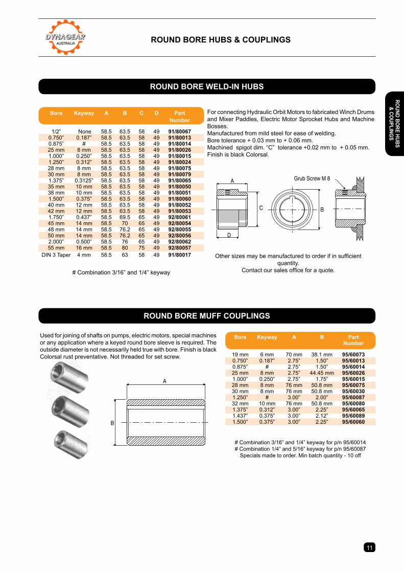
RoUnD BoRe HUBs & coUPLInGs
For connecting Hydraulic Orbit Motors to fabricated Winch Drums and Mixer Paddles, Electric Motor Sprocket Hubs and Machine Bosses.Manufactured from mild steel for ease of welding. Bore tolerance + 0.03 mm to + 0.06 mm. Machined spigot dim. “C” tolerance +0.02 mm to + 0.05 mm. Finish is black Colorsal.
Other sizes may be manufactured to order if in sufficient quantity.
Contact our sales office for a quote.# Combination 3/16” and 1/4” keyway
Grub Screw M 8A
C
D
B
Used for joining of shafts on pumps, electric motors, special machines or any application where a keyed round bore sleeve is required. The outside diameter is not necessarily held true with bore. Finish is black Colorsal rust preventative. Not threaded for set screw.
# Combination 3/16” and 1/4” keyway for p/n 95/60014# Combination 1/4” and 5/16” keyway for p/n 95/60087
Specials made to order. Min batch quantity - 10 off
B
A
RoUnD BoRe WeLD-In HUBs
RoUnD BoRe MUFF coUPLInGs
Bore Keyway A B c D Part number
1/2” None 58.5 63.5 58 49 91/80067 0.750” 0.187” 58.5 63.5 58 49 91/80013 0.875” # 58.5 63.5 58 49 91/80014 25 mm 8 mm 58.5 63.5 58 49 91/80026 1.000” 0.250” 58.5 63.5 58 49 91/80015 1.250” 0.312” 58.5 63.5 58 49 91/80024 28 mm 8 mm 58.5 63.5 58 49 91/80075 30 mm 8 mm 58.5 63.5 58 49 91/80079 1.375” 0.3125” 58.5 63.5 58 49 91/80065 35 mm 10 mm 58.5 63.5 58 49 91/80050 38 mm 10 mm 58.5 63.5 58 49 91/80051 1.500” 0.375” 58.5 63.5 58 49 91/80060 40 mm 12 mm 58.5 63.5 58 49 91/80052 42 mm 12 mm 58.5 63.5 58 49 91/80053 1.750” 0.437” 58.5 69.5 65 49 92/80061 45 mm 14 mm 58.5 70 65 49 92/80054 48 mm 14 mm 58.5 76.2 65 49 92/80055 50 mm 14 mm 58.5 76.2 65 49 92/80056 2.000” 0.500” 58.5 76 65 49 92/80062 55 mm 16 mm 58.5 80 75 49 92/80057 DIN 3 Taper 4 mm 58.5 63 58 49 91/80017
Bore Keyway A B Part number
19 mm 6 mm 70 mm 38.1 mm 95/60073 0.750” 0.187” 2.75” 1.50” 95/60013 0.875” # 2.75” 1.50” 95/60014 25 mm 8 mm 2.75” 44.45 mm 95/60026 1.000” 0.250” 2.75” 1.75” 95/60015 28 mm 8 mm 76 mm 50.8 mm 95/60075 30 mm 8 mm 76 mm 50.8 mm 95/60030 1.250” # 3.00” 2.00” 95/60087 32 mm 10 mm 76 mm 50.8 mm 95/60080 1.375” 0.312” 3.00” 2.25” 95/60065 1.437” 0.375” 3.00” 2.12” 95/60089 1.500” 0.375” 3.00” 2.25” 95/60060
RoUnD BoRe HUBs & coUPLInGs

63 s
eRIe
s
R
nD
Bo
Re
cLA
63
CLA
Round & Taper Bore
Round & Taper Bore
101.5
CLC
CLB
Round Bore
CLB
CLC
CLD
SL
127
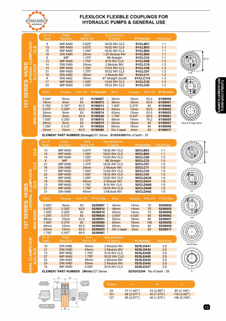
FLeXILocK FLeXIBLe coUPLInGs FoR HYDRAULIc PUMPs & GeneRAL Use
MAXIMUM MIsALIGnMent toLeRAnces. Axial Displacement. The element total axial clearance to hubs should be no less than 2 mm or no greater than 4 mm total.Parallel offset. Hub parallel offset to each other should not exceed 0.5mmAngular Misalignment. 1° per hub or total included angle of 2°
sPeeD. Consult factory for speeds exceeding 3000 RPM.
*Brief peak starting torque not to exceed 200% of continuous Torque. Consult factory for heavy shock loading or stop/ start loading.Continuous Power Ratings are for fluid power service, 10 hours per day with hubs within max. misalignment tolerance and temp not exceeding 100°C.Intermittent Power Ratings are for fluid power service up to 4 hours per day with hubs in true alignment and where the temperature does not exceed 80°C.
sPLIneD sHAFt connectIons.The FLEXILOCK range includes most of the splined shaft connec-tions currently utilized on hydraulic pumps and motors including imperial and metric sizes. All splined coupling hubs feature our popular CLAMPLOCK lateral or axial positive locking mechanisms which secure the coupling hub solidly on to the pump shaft and eliminate the spline wear associated with unlocked spline con-nections.
RoUnD BoRe KeYeD sHAFt connectIons.Most standard bore sizes available in imperial and metric sizes to fit standard hydraulic pumps and motors and IEC electric motor shaft standards. Stock availability of standard sizes enables imme-diate use of the couplings without having to undertake expensive machining of bores and keyways.
PoWeR RAtInGs MAtcHeD to APPLIcAtIon. The coupling design features a large gear teeth form with wide tooth face contact between the steel gear and the polymer ele-ment ensuring maximum power capacity in a small package over a long life cycle. Both splined and keyed hub designs are matched to effectively accommodate shaft sizes without excess weight penalty. BRoAD APPLIcAtIon VeRsAtILItY. The steel hub design permits ease of modification to suit special applications. Hub gear plates are available for attachment to customer supplied components. Long or short hub versions can be manufactured to special order. SLC and SLD type hubs can be arranged to incorporate sprockets or pulleys for auxiliary drives.
FLeXILocK sIZInG PRoGRAM - Consult your distributor to have your FLEXILOCK kit sized by our computer selection program.
A STANDARD OFF THE SHELF SHAFT COUPLING SYSTEM DEVELOPED SPECIALLY FOR HEAVY DUTY FLUID POWER APPLICATIONS
101 Series Complete coupling127 Series CLC
127 Series round bore 101 Series round bore
63 Series round bore
101 Series CLB63 Series CLA
12
FOR SHAFT SIZES SEE HYDRAULIC MOTOR & PUMP STANDARDS-PAGE 4 & 5 & ELECTRIC MOTOR STANDARDS PAGE 5
PeRFoRMAnce sPecIFIcAtIons. Continuous Continuous Intermittent Intermittent SERIES Power/Rev* Torque Power/Rev* Torque 63 0.0118 kW 113 Nm 0.0165 kW 157 Nm (Code 90) 0.0158 hp 83 ft lbs 0.0221 hp 116 ft lbs 101 0.0354 kW 339 Nm 0.0469 kW 475 Nm (Code 91) 0.0475 hp 250 ft lbs 0.0665 hp 350 ft lbs 127 0.0661 kW 632 Nm 0.0915 kW 884 Nm (Code 92) 0.0887 hp 466 ft lbs 0.1242 hp 652 ft lbs
No of Origin Nom Specifications Teeth Standard Spline OD of Spline Pt Number Weight(kg) 9 IMP ANSI 0.625” 16/32 INV CL5 90/CLA01 0.5 11 IMP ANSI 0.750” 16/32 INV CL5 90/CLA02 0.5 13 IMP ANSI 0.875” 16/32 INV CL5 90/CLA03 0.5 15 IMP ANSI 1.000” 16/32 INV CL5 90/CLA04 0.5
Bore Keyway Hub OD Pt Number Bore Keyway Hub OD Pt Number
0.625” 0.156” 45 90/90012 24mm 8mm 45 90/90074 19mm 6mm 45 90/90073 1.000” 0.250” 45 90/90015 0.750” 0.187” 45 90/90013 Din 2 taper 3mm 45 90/90016 0.875” 0.250” 45 90/90014 Din 3 taper 4mm 45 90/90017 eLeMent PARt nUMBeR (White) 63 Series 90/03/05741 No of teeth - 29
FLeX
IBLe
coU
PLIn
Gs &
Re
PLAc
eMen
t eL
eMen
ts
13
63
CLA
Round & Taper Bore
Round & Taper Bore
101.5
CLC
CLB
Round Bore
CLB
CLC
CLD
SL
127
63
CLA
Round & Taper Bore
Round & Taper Bore
101.5
CLC
CLB
Round Bore
CLB
CLC
CLD
SL
127
FLeXILocK FLeXIBLe coUPLInGs FoR HYDRAULIc PUMPs & GeneRAL Use
KEYED SHAFT DRIVE
SPLINED SHAFT DRIVE
Set screwM8
SHAFTS MAY PROTRUDETHROUGH TO CENTRE LINE
OF COUPLING ELEMENT
"CLAMPLOCK"TYPE "CL" OR "SL"SPLINE LOCKING
MECHANISM
ROUND BORE HUB WITH KEYWAYAND SET SCREWS
B
C
AA
101
seR
Ies
HU
Bs
LA
teR
AL
cLA
MPL
oc
K
R
nD
Bo
Re
cLc
/cLD
c
LB
127
seR
Ies
HU
Bs
AXI
AL
cLA
MPL
oc
K
LAte
RA
L c
LAM
PLo
cK
sLD
, sLe
R
nD
Bo
Re
cLD
c
Lc
cLB
No of Origin Nom Specifications Teeth Standard Spline OD of Spline Pt number Weight(kg)
9 IMP ANSI 0.625” 16/32 INV CL5 91/cLB01 1.1 13 IMP ANSI 0.875” 16/32 INV CL5 91/cLB03 1.1 15 IMP ANSI 1.000” 16/32 INV CL5 91/cLB04 1.1 18 DIN 5480 25mm 1.25 Module INV 91/cLB20 1.1 6 IMP 1.375” 6B Straight 91/cLc33 1.1 13 IMP ANSI 1.750” 8/16 INV CL5 91/cLD08 1.3 14 DIN 5480 30mm 2 Module INV 91/cLc10 1.3 14 IMP ANSI 1.250” 12/24 INV CL5 91/cLc06 1.3 21 IMP ANSI 1.375” 16/32 INV CL5 91/cLc07 1.3 16 DIN 5480 35mm 2 Module INV 91/cLc11 1.3 8 DIN 5462 36mm 8T Straight 32x36 91/cLc115 1.3 17 IMP ANSI 1.500” 12/24 INV CL5 91/cLc32 1.3 23 IMP ANSI 1.500” 16/32 INV CL5 91/cLc43 1.3
Bore Keyway Hub OD Pt number Bore Keyway Hub OD Pt number
0.500” None 63 91/90067 35mm 10mm 63.5 91/90050 19mm 6mm 63 91/90073 38mm 10mm 63.5 91/90051 0.750” 0.187” 63.5 91/90013 1.500” 0.375” 63 91/90060 0.875” 0.250” 63.5 91/90014 40mm 12mm 63.5 91/90052 24mm 8mm 63 91/90074 42mm 12mm 63.5 91/90053 25mm 8mm 63.5 91/90026 1.750” 0.437” 69.5 91/90061 1.000” 0.250” 63 91/90015 48mm 14mm 76.2 91/90055 28mm 8mm 63 91/90075 55mm 16mm 80 91/90057 1.250” 0.312” 63 91/90024 60mm 18mm 90 91/90058 32mm 10mm 63.5 91/90080 Din 3 taper 4mm 63 91/90017
eLeMent PARt nUMBeR (orange) 101 Series 91/03/03691No of teeth - 30
No of Origin Nom Specifications Teeth Standard Spline OD of Spline Pt number Weight(kg)
13 IMP ANSI 0.875” 16/32 INV CL5 92/cLB03 1.1 15 IMP ANSI 1.000” 16/32 INV CL5 92/cLB04 1.1 14 IMP ANSI 1.250” 12/24 INV CL5 92/cLc06 1.5 6 IMP 1.375” 6B Straight 92/cLc33 1.5 21 IMP ANSI 1.375” 16/32 INV CL5 92/cLc07 1.5 16 DIN 5480 35mm 2 Module INV 92/cLc11 1.5 17 IMP ANSI 1.500” 12/24 INV CL5 92/cLc32 1.5 23 IMP ANSI 1.500” 16/32 INV CL5 92/cLc43 1.5 14 IMP ANSI 1.500” 10/20 INV CL5 92/cLDA36 1.8 18 DIN 5480 40mm 2 Module INV 92/cLDA41 1.8 13 IMP ANSI 1.750” 8/16 INV CL5 92/cLDA08 1.8 27 IMP ANSI 1.750” 16/32 INV CL5 92/cLDA09 1.8 21 DIN 5480 45mm 2 Module INV 92/cLDA42 1.8
Bore Keyway Hub OD Pt Number Bore Keyway Hub OD Pt Number
0.500” None 63 92/90067 45mm 14mm 75 92/90054 0.875” 0.250” 63.5 92/90014 48mm 14mm 75 92/90055 1.000” 0.250” 63 92/90015 50mm 14mm 75 92/90056 1.250” 0.312” 63 92/90024 2.000” 0.500” 80 92/90062 38mm 10mm 63.5 92/90051 55mm 16mm 80 92/90057 1.500” 0.375” 63 92/90060 60mm 18mm 106 92/90058 40mm 12mm 63.5 92/90052 65mm 18mm 90 92/90059 42mm 12mm 63.5 92/90053 Din 3 taper 4mm 63 92/90017 1.750” 0.437” 69.5 92/90061 No of Origin Nom Specifications Teeth Standard Spline OD of Spline Pt number Weight(kg)
18 DIN 5480 40mm 2 Module INV 92/sLDA41 2.8 21 DIN 5480 45mm 2 Module INV 92/sLDA42 2.8 13 IMP ANSI 1.750” 8/16 INV CL5 92/sLeA08 2.8 27 IMP ANSI 1.750” 16/32 INV CL5 92/sLeA09 2.8 23 DIN 5482 48mm 2 Module INV 92/sLeA44 2.8 24 DIN 5480 50mm 2 Module INV 92/sLeA45 2.8 15 IMP ANSI 2.000” 8/16 INV CL5 92/sLeA37 2.8 eLeMent PARt nUMBeR (White)127 Series 92/03/03244 No of teeth - 28
Series A B C
63 37 (1.457”) 53 (2.087”) 80 (3.149”) 101 68 (2.677”) 40 (1.575”) 116 (4.567”) 127 68 (2.677”) 40 (1.575”) 146 (5.748”)
FLeXIBLe coUPLInGs & RePLAceM
ent eLeMents
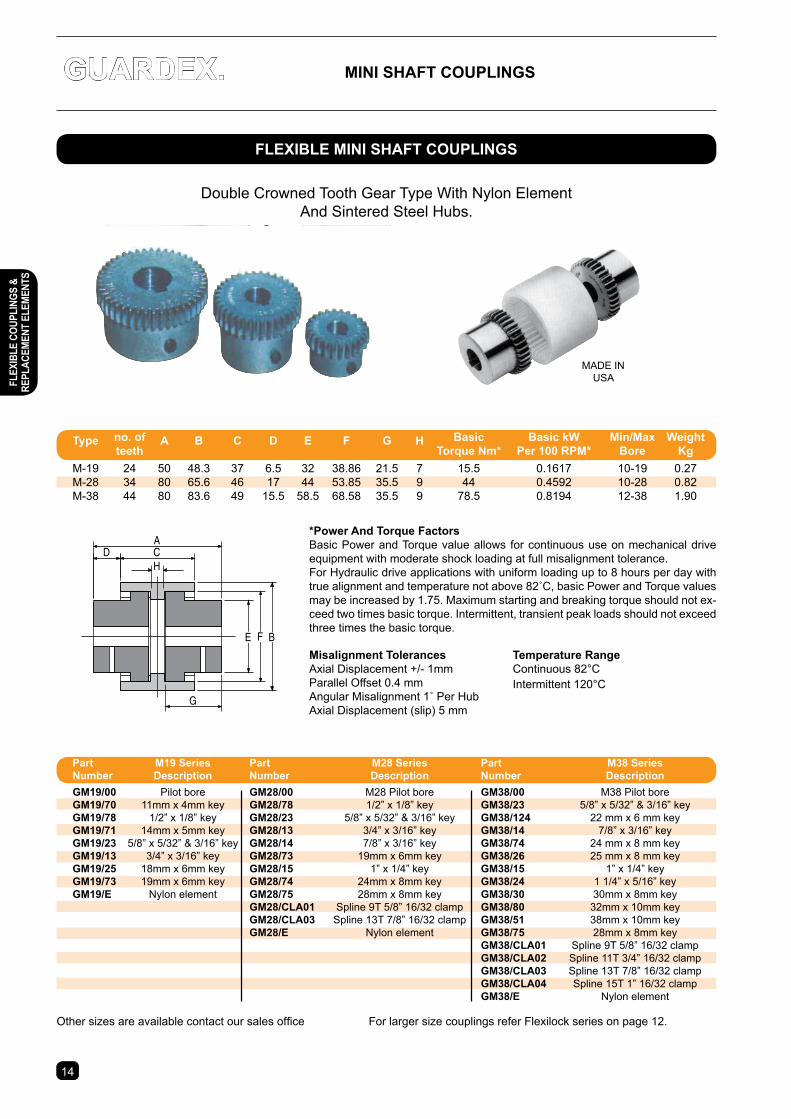
GUARDeX. MInI sHAFt coUPLInGs
C
B
D
E F
H
A
G
*Power And torque FactorsBasic Power and Torque value allows for continuous use on mechanical drive equipment with moderate shock loading at full misalignment tolerance.For Hydraulic drive applications with uniform loading up to 8 hours per day with true alignment and temperature not above 82˚C, basic Power and Torque values may be increased by 1.75. Maximum starting and breaking torque should not ex-ceed two times basic torque. Intermittent, transient peak loads should not exceed three times the basic torque.
Double Crowned Tooth Gear Type With Nylon Element And Sintered Steel Hubs.
MADE IN USA
Other sizes are available contact our sales office For larger size couplings refer Flexilock series on page 12.
Misalignment tolerancesAxial Displacement +/- 1mmParallel Offset 0.4 mmAngular Misalignment 1˚ Per HubAxial Displacement (slip) 5 mm
temperature RangeContinuous 82°CIntermittent 120°C
1514
FLeXIBLe MInI sHAFt coUPLInGs
type no. of A B c D e F G H Basic Basic kW Min/Max Weight teeth torque nm* Per 100 RPM* Bore Kg M-19 24 50 48.3 37 6.5 32 38.86 21.5 7 15.5 0.1617 10-19 0.27 M-28 34 80 65.6 46 17 44 53.85 35.5 9 44 0.4592 10-28 0.82 M-38 44 80 83.6 49 15.5 58.5 68.58 35.5 9 78.5 0.8194 12-38 1.90
Part M19 series Part M28 series Part M38 series number Description number Description number Description GM19/00 Pilot bore GM28/00 M28 Pilot bore GM38/00 M38 Pilot bore GM19/70 11mm x 4mm key GM28/78 1/2” x 1/8” key GM38/23 5/8” x 5/32” & 3/16” key GM19/78 1/2” x 1/8” key GM28/23 5/8” x 5/32” & 3/16” key GM38/124 22 mm x 6 mm key GM19/71 14mm x 5mm key GM28/13 3/4” x 3/16” key GM38/14 7/8” x 3/16” key GM19/23 5/8” x 5/32” & 3/16” key GM28/14 7/8” x 3/16” key GM38/74 24 mm x 8 mm key GM19/13 3/4” x 3/16” key GM28/73 19mm x 6mm key GM38/26 25 mm x 8 mm key GM19/25 18mm x 6mm key GM28/15 1” x 1/4” key GM38/15 1” x 1/4” key GM19/73 19mm x 6mm key GM28/74 24mm x 8mm key GM38/24 1 1/4” x 5/16” key GM19/e Nylon element GM28/75 28mm x 8mm key GM38/30 30mm x 8mm key GM28/cLA01 Spline 9T 5/8” 16/32 clamp GM38/80 32mm x 10mm key GM28/cLA03 Spline 13T 7/8” 16/32 clamp GM38/51 38mm x 10mm key GM28/e Nylon element GM38/75 28mm x 8mm key GM38/cLA01 Spline 9T 5/8” 16/32 clamp GM38/cLA02 Spline 11T 3/4” 16/32 clamp GM38/cLA03 Spline 13T 7/8” 16/32 clamp GM38/cLA04 Spline 15T 1” 16/32 clamp GM38/e Nylon element
FLeX
IBLe
coU
PLIn
Gs &
Re
PLAc
eMen
t eL
eMen
ts
1514
DYnAGeAR RePLAceMent eLeMents
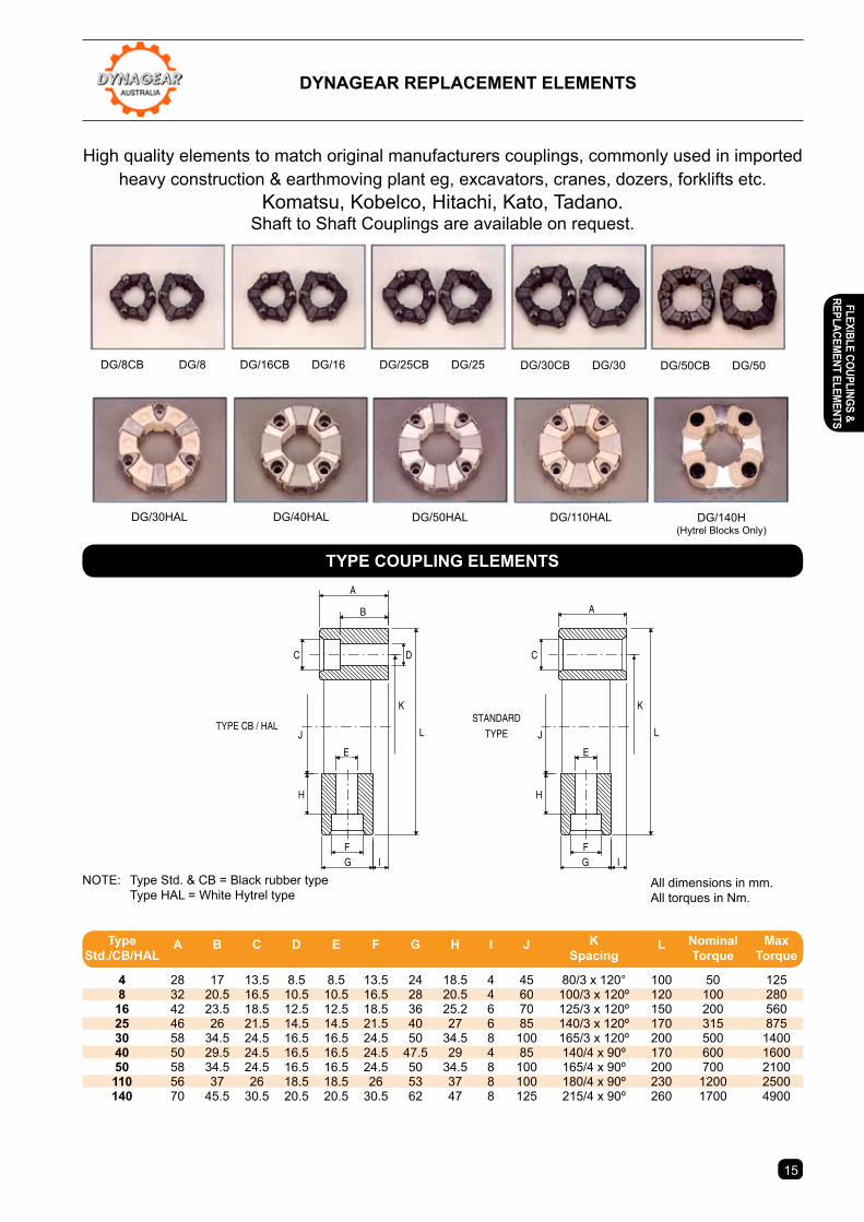
High quality elements to match original manufacturers couplings, commonly used in imported heavy construction & earthmoving plant eg, excavators, cranes, dozers, forklifts etc.
Komatsu, Kobelco, Hitachi, Kato, Tadano.Shaft to Shaft Couplings are available on request.
A
B
C D
E
FG
H
I
J
K
L
A
C
E
FG
H
I
J
K
LTYPE CB / HAL
STANDARD
TYPE
NOTE: Type Std. & CB = Black rubber type Type HAL = White Hytrel type
All dimensions in mm. All torques in Nm.
DG/8CB DG/8 DG/16CB DG/16 DG/25CB DG/25 DG/30CB DG/30 DG/50CB DG/50
DG/30HAL DG/40HAL DG/50HAL DG/110HAL DG/140H(Hytrel Blocks Only)
tYPe coUPLInG eLeMents
type A B c D e F G H I J K L nominal Max std./cB/HAL spacing torque torque
4 28 17 13.5 8.5 8.5 13.5 24 18.5 4 45 80/3 x 120° 100 50 125 8 32 20.5 16.5 10.5 10.5 16.5 28 20.5 4 60 100/3 x 120º 120 100 280 16 42 23.5 18.5 12.5 12.5 18.5 36 25.2 6 70 125/3 x 120º 150 200 560 25 46 26 21.5 14.5 14.5 21.5 40 27 6 85 140/3 x 120º 170 315 875 30 58 34.5 24.5 16.5 16.5 24.5 50 34.5 8 100 165/3 x 120º 200 500 1400 40 50 29.5 24.5 16.5 16.5 24.5 47.5 29 4 85 140/4 x 90º 170 600 1600 50 58 34.5 24.5 16.5 16.5 24.5 50 34.5 8 100 165/4 x 90º 200 700 2100 110 56 37 26 18.5 18.5 26 53 37 8 100 180/4 x 90º 230 1200 2500 140 70 45.5 30.5 20.5 20.5 30.5 62 47 8 125 215/4 x 90º 260 1700 4900
FLeXIBLe coUPLInGs & RePLAceM
ent eLeMents
16
UnIVeRsAL JoInt DRIVe tRAIn coMPonents sPLIneD YoKes AnD coMPAnIon FLAnGes
SAFETY - Contact with spinning driveshafts can result in serious injury. Safety guards should be fitted to protect personnel from contact with rotating shafts, or to contain the shaft in the event of failure.
1310SERIES
109.8 (4.323")1310 =88.10 (3.468")1350 =98.43 (3.876")
3/8" HEXDRIVE 1310 =26.98 (1.062")
1350 =30.16 (1.187")
1350SERIES
112.2 (4.417")
1310 =88.10 (3.468")1350 =98.43 (3.876")
1310SERIES
82.5 (3.250")
1350SERIES
91.5 (3.602")
1310 =26.98 (1.062")1350 =30.16 (1.187")
3/8" HEXDRIVE
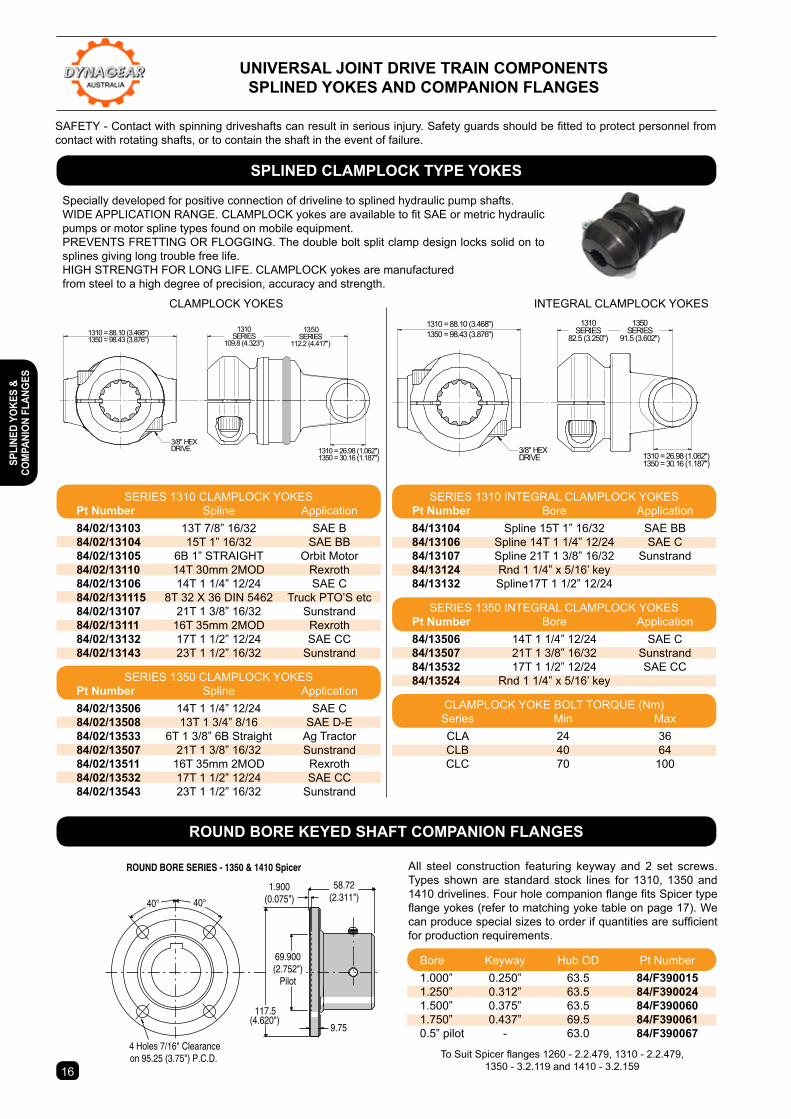
Specially developed for positive connection of driveline to splined hydraulic pump shafts.WIDE APPLICATION RANGE. CLAMPLOCK yokes are available to fit SAE or metric hydraulic pumps or motor spline types found on mobile equipment. PREVENTS FRETTING OR FLOGGING. The double bolt split clamp design locks solid on to splines giving long trouble free life.HIGH STRENGTH FOR LONG LIFE. CLAMPLOCK yokes are manufactured from steel to a high degree of precision, accuracy and strength.
All steel construction featuring keyway and 2 set screws. Types shown are standard stock lines for 1310, 1350 and 1410 drivelines. Four hole companion flange fits Spicer type flange yokes (refer to matching yoke table on page 17). We can produce special sizes to order if quantities are sufficient for production requirements.
40°
1310 = 26.98 (1.062")1350 = 30.16 (1.187")
1310 = 88.10 (3.468")1350 = 98.43 (3.876")
56.7
1.9(0.075")
4 Holes 7/16" Clearance on 95.25 (3.75") P.C.D.
9.75
CLC & CLD SERIES - 1310, 1350 & 1410 Spicer
40°
117.5(4.620")
69.9(2.752")
Pilot
1350SERIES
112.2 (4.417")
1310SERIES
109.8 (4.323")
40°Number ofClampingBolts "B"
4 Holes Tapped 7/16" UNCon 95.25 (3.75") P.C.D.
40°
CLDA SERIES - 1310, 1350 & 1410 Spicer
1.900(0.075")
4 Holes 7/16" Clearance on 95.25 (3.75") P.C.D.
9.75
40°40°
69.900(2.752")
Pilot
(4.620")117.5
58.72(2.311")
65.6(2.582")
16.3
117.5
69.9(2.752")
Pilot
5/16" UNF
(4.620")
65.6(2.582")
16.3Number ofClampingBolts "B" 145
95.25(3.750")
Pilot
(5.708")
4 Holes Tapped 1/2" UNCon 120.65 (4.75") P.C.D.
40°40°
CLDA SERIES - 1410, 1480 & 1550 Spicer
ROUND BORE SERIES - 1350 & 1410 Spicer
5/16" UNF
1310 = 26.98 (1.062")1350 = 30.16 (1.187")
1310 = 88.10 (3.468")1350 = 98.43 (3.876")
1350SERIES
91.5 (3.602")
1310SERIES
82.5 (3.250")
3/8"HexDrive
3/8"HexDrive
CLAMPLOCK YOKES INTEGRAL CLAMPLOCK YOKES
To Suit Spicer flanges 1260 - 2.2.479, 1310 - 2.2.479, 1350 - 3.2.119 and 1410 - 3.2.159
sPLIneD cLAMPLocK tYPe YoKes
RoUnD BoRe KeYeD sHAFt coMPAnIon FLAnGes
Bore Keyway Hub OD Pt Number1.000” 0.250” 63.5 84/F3900151.250” 0.312” 63.5 84/F3900241.500” 0.375” 63.5 84/F3900601.750” 0.437” 69.5 84/F3900610.5” pilot - 63.0 84/F390067
SERIES 1310 CLAMPLOCK YOKES Pt number Spline Application 84/02/13103 13T 7/8” 16/32 SAE B 84/02/13104 15T 1” 16/32 SAE BB 84/02/13105 6B 1” STRAIGHT Orbit Motor 84/02/13110 14T 30mm 2MOD Rexroth 84/02/13106 14T 1 1/4” 12/24 SAE C 84/02/131115 8T 32 X 36 DIN 5462 Truck PTO’S etc 84/02/13107 21T 1 3/8” 16/32 Sunstrand 84/02/13111 16T 35mm 2MOD Rexroth 84/02/13132 17T 1 1/2” 12/24 SAE CC 84/02/13143 23T 1 1/2” 16/32 Sunstrand
SERIES 1350 CLAMPLOCK YOKES Pt number Spline Application 84/02/13506 14T 1 1/4” 12/24 SAE C 84/02/13508 13T 1 3/4” 8/16 SAE D-E 84/02/13533 6T 1 3/8” 6B Straight Ag Tractor 84/02/13507 21T 1 3/8” 16/32 Sunstrand 84/02/13511 16T 35mm 2MOD Rexroth 84/02/13532 17T 1 1/2” 12/24 SAE CC 84/02/13543 23T 1 1/2” 16/32 Sunstrand
SERIES 1310 INTEGRAL CLAMPLOCK YOKES Pt number Bore Application 84/13104 Spline 15T 1” 16/32 SAE BB 84/13106 Spline 14T 1 1/4” 12/24 SAE C 84/13107 Spline 21T 1 3/8” 16/32 Sunstrand 84/13124 Rnd 1 1/4” x 5/16’ key 84/13132 Spline17T 1 1/2” 12/24
SERIES 1350 INTEGRAL CLAMPLOCK YOKES Pt number Bore Application 84/13506 14T 1 1/4” 12/24 SAE C 84/13507 21T 1 3/8” 16/32 Sunstrand 84/13532 17T 1 1/2” 12/24 SAE CC 84/13524 Rnd 1 1/4” x 5/16’ key
CLAMPLOCK YOKE BOLT TORQUE (Nm) Series Min Max CLA 24 36 CLB 40 64 CLC 70 100
sPLI
neD
YoKe
s &
coM
PAnI
on F
LAnG
es
17
UnIVeRsAL JoInt DRIVe tRAIn coMPonents sPLIneD YoKes AnD coMPAnIon FLAnGes
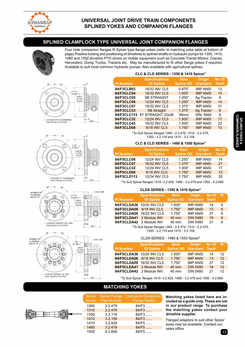
Four hole companion flanges fit Spicer type flange yokes (refer to matching yoke table at bottom of page).Positive locking and positioning of drivelines to splined shafts on hydraulic pumps for 1350, 1410, 1480 and 1550 driveline PTO drives on mobile equipment such as Concrete Transit Mixers, Cranes, Harvesters, Dump Trucks, Tractors etc. May be manufactured to fit other flange yokes if required. Available to suit most common hydraulic pumps. Also available with agricultural splines.
40°
1310 = 26.98 (1.062")1350 = 30.16 (1.187")
1310 = 88.10 (3.468")1350 = 98.43 (3.876")
56.7
1.9(0.075")
4 Holes 7/16" Clearance on 95.25 (3.75") P.C.D.
9.75
CLC & CLD SERIES - 1310, 1350 & 1410 Spicer
40°
117.5(4.620")
69.9(2.752")
Pilot
1350SERIES
112.2 (4.417")
1310SERIES
109.8 (4.323")
40°Number ofClampingBolts "B"
4 Holes Tapped 7/16" UNCon 95.25 (3.75") P.C.D.
40°
CLDA SERIES - 1310, 1350 & 1410 Spicer
1.900(0.075")
4 Holes 7/16" Clearance on 95.25 (3.75") P.C.D.
9.75
40°40°
69.900(2.752")
Pilot
(4.620")117.5
58.72(2.311")
65.6(2.582")
16.3
117.5
69.9(2.752")
Pilot
5/16" UNF
(4.620")
65.6(2.582")
16.3Number ofClampingBolts "B" 145
95.25(3.750")
Pilot
(5.708")
4 Holes Tapped 1/2" UNCon 120.65 (4.75") P.C.D.
40°40°
CLDA SERIES - 1410, 1480 & 1550 Spicer
ROUND BORE SERIES - 1350 & 1410 Spicer
5/16" UNF
1310 = 26.98 (1.062")1350 = 30.16 (1.187")
1310 = 88.10 (3.468")1350 = 98.43 (3.876")
1350SERIES
91.5 (3.602")
1310SERIES
82.5 (3.250")
3/8"HexDrive
3/8"HexDrive
Matching yokes listed here are in-cluded as a guide only. these are not in our product range. to purchase the matching yokes contact your driveline supplier.Flanged adaptors to suit other Spicer sizes may be available. Contact our sales office.
Ø117.4(4.620”)
Ø 69.9(2.752”)PILOT
4 HOLES 7/16” CLEARANCEON A 95.25 (3.75”) PCD
40˚ 40˚
956.6
2
40˚ 40˚
65.716.4
Ø117.4(4.620”)
69.9(2.752”)PILOT
4 HOLES TAPPED 7/16” UNCON A 95.25 (3.75”) PCD
5/16” UNFNUMBER OF CLAMPINGBOLTS “B”
Ø
40˚ 40˚
65.7
16.4
5/16” UNF
4 HOLES TAPPED 1/2” UNCON A 120.65 (4.75”) PCD
95.25(3.750”)PILOT
145(5.708”)
NUMBER OF CLAMPINGBOLTS “B”
61.6
2
14
40˚ 40˚
145(5.708”)
95.25(3.750”)PILOT
4 HOLES 1/2” CLEARANCEON A 120.65 (4.75”) PCD
Ø
Ø
cLc & cLD seRIes - 1350 & 1410 spicer*
cLc & cLD seRIes - 1480 & 1550 spicer*
cLDA seRIes - 1350 & 1410 spicer*
CLDA SERIES - 1480 & 1550 Spicer*
*To Suit Spicer flanges 1260 - 2.2.479, 1310 - 2.2.479, 1350 - 3.2.119 and 1410 - 3.2.159
*To Suit Spicer flanges 1410- 3.2.429, 1480 - 3.2.479 and 1550 - 4.2.669
*To Suit Spicer flanges 1410- 3.2.429, 1480 - 3.2.479 and 1550 - 4.2.669
*To Suit Spicer flanges 1260 - 2.2.479, 1310 - 2.2.479, 1350 - 3.2.119 and 1410 - 3.2.159
sPLIneD cLAMPLocK tYPe UnIVeRsAL JoInt coMPAnIon FLAnGes
MAtcHInG YoKes
Specifications Nom Origin No OfPt number of spline spline oD standard teeth84/F3cLB03 16/32 INV CL5 0.875” IMP ANSI 1384/F3cLc04 16/32 INV CL5 1.000” IMP ANSI 1584/F3cLc05 6B STRAIGHT 1.000” Ag Tractor 684/F3cLc06 12/24 INV CL5 1.250” IMP ANSI 1484/F3cLc07 16/32 INV CL5 1.375” IMP ANSI 2184/F3cLc33 6B Straight 1.375” Ag Tractor 684/F3cLc115 8T STRAIGHT 32x36 36mm DIN. 5462 884/F3cLc32 12/24 INV CL5 1.500” IMP ANSI 1784/F3cLc43 16/32 INV CL5 1.500” IMP ANSI 2384/F3cLD08 8/16 INV CL5 1.750” IMP ANSI 13
Specifications Nom Origin No Of “B”Pt number of spline spline oD standard teeth 84/F5cLDA36 10/20 INV CL5 1.500” IMP ANSI 14 1284/F5cLDA08 8/16 INV CL5 1.750” IMP ANSI 13 1284/F5cLDA09 16/32 INV CL5 1.750” IMP ANSI 27 1284/F5cLDA41 2 Module INV 40 mm DIN 5480 18 1284/F5cLDA42 2 Module INV 45 mm DIN 5480 21 12
Specifications Nom Origin No Of “B”Pt number of spline spline oD standard teeth 84/F3cLDA36 10/20 INV CL5 1.500” IMP ANSI 14 684/F3cLDA08 8/16 INV CL5 1.750” IMP ANSI 13 684/F3cLDA09 16/32 INV CL5 1.750” IMP ANSI 27 684/F3cLDA41 2 Module INV 40 mm DIN 5480 18 684/F3cLDA42 2 Module INV 45 mm DIN 5480 21 6
Specifications Nom Origin No OfPt number of spline spline oD standard teeth84/F5cLc06 12/24 INV CL5 1.250” IMP ANSI 1484/F5cLc07 16/32 INV CL5 1.375” IMP ANSI 2184/F5cLc32 12/24 INV CL5 1.500” IMP ANSI 1784/F5cLD08 8/16 INV CL5 1.750” IMP ANSI 1384/F5cLD113 12/24 INV CL5 1.750” IMP ANSI 20
Spicer Spicer Flange Clamplock Companion Series Yoke Number Flange Series 1260 2.2.479 84/F3 ...... 1310 2.2.479 84/F3 ...... 1350 3.2.119 84/F3 ...... 1410 3.2.159 84/F3 ...... 1410 3.2.429 84/F5 ...... 1480 3.2.479 84/F5 ...... 1550 4.2.669 84/F5 ......
sPLIneD YoKes & coM
PAnIon FLAnGes
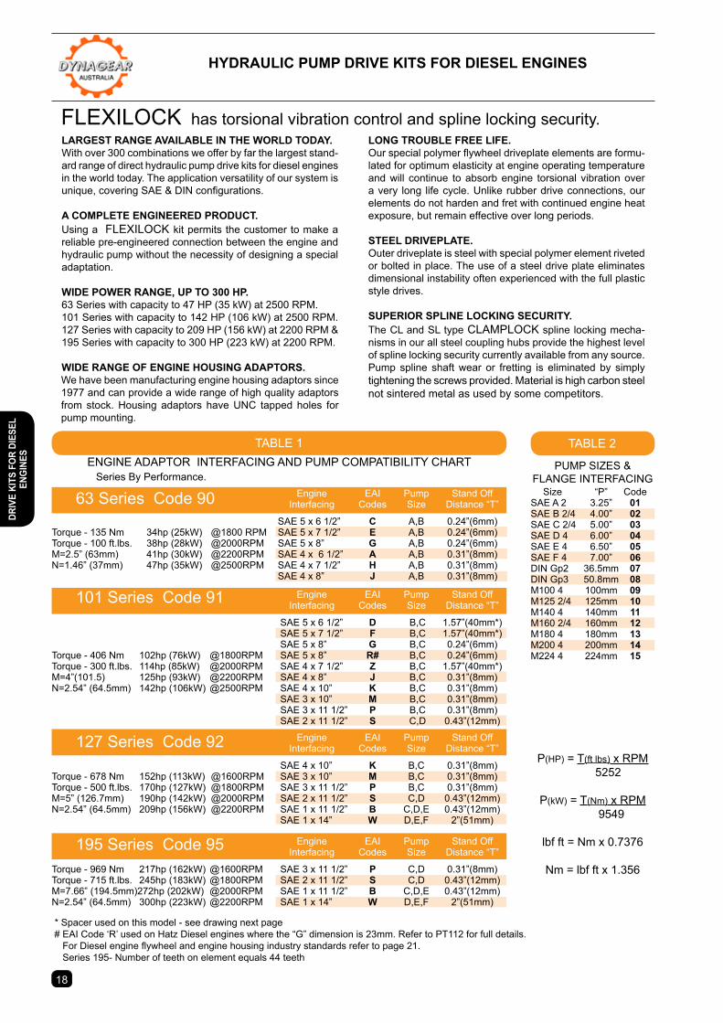
TABLE 1ENGINE ADAPTOR INTERFACING AND PUMP COMPATIBILITY CHART
101 Series Code 91
127 Series Code 92
195 Series Code 95
Series By Performance.
P(HP) = T(ft lbs) x RPM 5252
P(kW) = T(Nm) x RPM 9549
lbf ft = Nm x 0.7376
Nm = lbf ft x 1.356
LARGest RAnGe AVAILABLe In tHe WoRLD toDAY.With over 300 combinations we offer by far the largest stand-ard range of direct hydraulic pump drive kits for diesel engines in the world today. The application versatility of our system is unique, covering SAE & DIN configurations.
A coMPLete enGIneeReD PRoDUct.Using a FLEXILOCK kit permits the customer to make a reliable pre-engineered connection between the engine and hydraulic pump without the necessity of designing a special adaptation.
WIDe PoWeR RAnGe, UP to 300 HP. 63 Series with capacity to 47 HP (35 kW) at 2500 RPM. 101 Series with capacity to 142 HP (106 kW) at 2500 RPM. 127 Series with capacity to 209 HP (156 kW) at 2200 RPM & 195 Series with capacity to 300 HP (223 kW) at 2200 RPM.
WIDe RAnGe oF enGIne HoUsInG ADAPtoRs.We have been manufacturing engine housing adaptors since 1977 and can provide a wide range of high quality adaptors from stock. Housing adaptors have UNC tapped holes for pump mounting.
FLEXILOCK has torsional vibration control and spline locking security.LonG tRoUBLe FRee LIFe.Our special polymer flywheel driveplate elements are formu-lated for optimum elasticity at engine operating temperature and will continue to absorb engine torsional vibration over a very long life cycle. Unlike rubber drive connections, our elements do not harden and fret with continued engine heat exposure, but remain effective over long periods.
steeL DRIVePLAte.Outer driveplate is steel with special polymer element riveted or bolted in place. The use of a steel drive plate eliminates dimensional instability often experienced with the full plastic style drives.
sUPeRIoR sPLIne LocKInG secURItY.The CL and SL type CLAMPLOCK spline locking mecha-nisms in our all steel coupling hubs provide the highest level of spline locking security currently available from any source. Pump spline shaft wear or fretting is eliminated by simply tightening the screws provided. Material is high carbon steel not sintered metal as used by some competitors.
* Spacer used on this model - see drawing next page # EAI Code ‘R’ used on Hatz Diesel engines where the “G” dimension is 23mm. Refer to PT112 for full details. For Diesel engine flywheel and engine housing industry standards refer to page 21. Series 195- Number of teeth on element equals 44 teeth
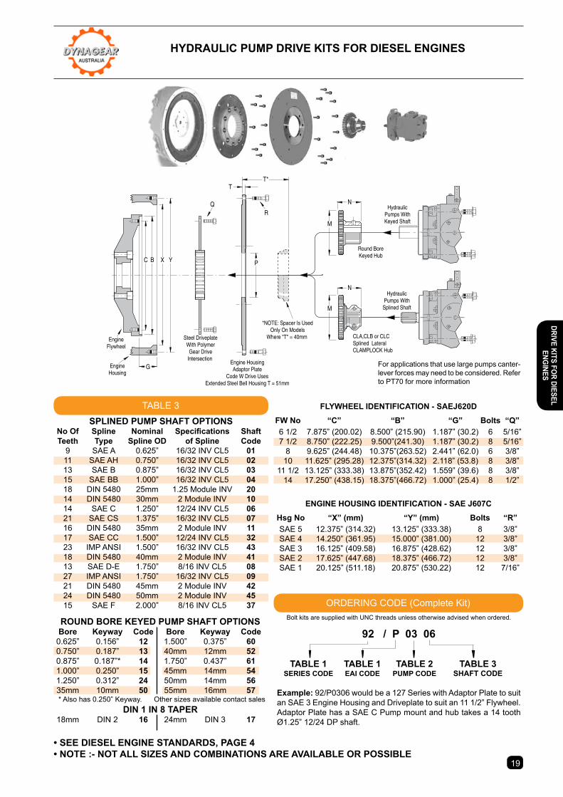
HYDRAULIc PUMP DRIVe KIts FoR DIeseL enGInes
1918
63 Series Code 90
TABLE 2
Engine EAI Pump Stand Off Interfacing Codes Size Distance “T”
SAE 5 x 6 1/2” c A,B 0.24”(6mm)Torque - 135 Nm 34hp (25kW) @1800 RPM SAE 5 x 7 1/2” e A,B 0.24”(6mm)Torque - 100 ft.lbs. 38hp (28kW) @2000RPM SAE 5 x 8” G A,B 0.24”(6mm)M=2.5” (63mm) 41hp (30kW) @2200RPM SAE 4 x 6 1/2” A A,B 0.31”(8mm)N=1.46” (37mm) 47hp (35kW) @2500RPM SAE 4 x 7 1/2” H A,B 0.31”(8mm) SAE 4 x 8” J A,B 0.31”(8mm)
Engine EAI Pump Stand Off Interfacing Codes Size Distance “T”
SAE 5 x 6 1/2” D B,C 1.57”(40mm*) SAE 5 x 7 1/2” F B,C 1.57”(40mm*) SAE 5 x 8” G B,C 0.24”(6mm)Torque - 406 Nm 102hp (76kW) @1800RPM SAE 5 x 8” R# B,C 0.24”(6mm)Torque - 300 ft.lbs. 114hp (85kW) @2000RPM SAE 4 x 7 1/2” Z B,C 1.57”(40mm*)M=4”(101.5) 125hp (93kW) @2200RPM SAE 4 x 8” J B,C 0.31”(8mm)N=2.54” (64.5mm) 142hp (106kW) @2500RPM SAE 4 x 10” K B,C 0.31”(8mm) SAE 3 x 10” M B,C 0.31”(8mm) SAE 3 x 11 1/2” P B,C 0.31”(8mm) SAE 2 x 11 1/2” s C,D 0.43”(12mm)
Engine EAI Pump Stand Off Interfacing Codes Size Distance “T”
SAE 4 x 10” K B,C 0.31”(8mm)Torque - 678 Nm 152hp (113kW) @1600RPM SAE 3 x 10” M B,C 0.31”(8mm)Torque - 500 ft.lbs. 170hp (127kW) @1800RPM SAE 3 x 11 1/2” P B,C 0.31”(8mm)M=5” (126.7mm) 190hp (142kW) @2000RPM SAE 2 x 11 1/2” s C,D 0.43”(12mm)N=2.54” (64.5mm) 209hp (156kW) @2200RPM SAE 1 x 11 1/2” B C,D,E 0.43”(12mm) SAE 1 x 14” W D,E,F 2”(51mm)
Engine EAI Pump Stand Off Interfacing Codes Size Distance “T”
Torque - 969 Nm 217hp (162kW) @1600RPM SAE 3 x 11 1/2” P C,D 0.31”(8mm)Torque - 715 ft.lbs. 245hp (183kW) @1800RPM SAE 2 x 11 1/2” s C,D 0.43”(12mm)M=7.66” (194.5mm)272hp (202kW) @2000RPM SAE 1 x 11 1/2” B C,D,E 0.43”(12mm)N=2.54” (64.5mm) 300hp (223kW) @2200RPM SAE 1 x 14” W D,E,F 2”(51mm)
PUMP SIZES & FLANGE INTERFACING Size “P” Code SAE A 2 3.25” 01 SAE B 2/4 4.00” 02 SAE C 2/4 5.00” 03 SAE D 4 6.00” 04 SAE E 4 6.50” 05 SAE F 4 7.00” 06DIN Gp2 36.5mm 07DIN Gp3 50.8mm 08M100 4 100mm 09M125 2/4 125mm 10M140 4 140mm 11M160 2/4 160mm 12M180 4 180mm 13M200 4 200mm 14M224 4 224mm 15
DRIV
e KI
ts F
oR D
Iese
L en
GIne
s
1918
Bolt kits are supplied with UNC threads unless otherwise advised when ordered.
92 / P 03 06 tABLe 1 tABLe 1 tABLe 2 tABLe 3 seRIes coDe eAI coDe PUMP coDe sHAFt coDe
example: 92/P0306 would be a 127 Series with Adaptor Plate to suit an SAE 3 Engine Housing and Driveplate to suit an 11 1/2” Flywheel. Adaptor Plate has a SAE C Pump mount and hub takes a 14 tooth Ø1.25” 12/24 DP shaft.
EngineFlywheel
EngineHousing
Steel DriveplateWith PolymerGear Drive
IntersectionEngine HousingAdaptor Plate
Code W Drive UsesExtended Steel Bell Housing T = 51mm
RQ
Round BoreKeyed Hub
CLA,CLB or CLCSplined LateralCLAMPLOCK Hub
HydraulicPumps With
Splined Shaft
HydraulicPumps WithKeyed Shaft
*NOTE: Spacer Is UsedOnly On Models
Where "T" = 40mm
M
M
N
N
T*
P
T
YXBC
G For applications that use large pumps canter-lever forces may need to be considered. Refer to PT70 for more information
HYDRAULIc PUMP DRIVe KIts FoR DIeseL enGInes
• see DIeseL enGIne stAnDARDs, PAGe 4• note :- not ALL sIZes AnD coMBInAtIons ARe AVAILABLe oR PossIBLe
TABLE 3
ORDERING CODE (Complete Kit)
RoUnD BoRe KeYeD PUMP sHAFt oPtIons Bore Keyway code Bore Keyway code 0.625” 0.156” 12 1.500” 0.375” 60 0.750” 0.187” 13 40mm 12mm 52 0.875” 0.187”* 14 1.750” 0.437” 61 1.000” 0.250” 15 45mm 14mm 54 1.250” 0.312” 24 50mm 14mm 56 35mm 10mm 50 55mm 16mm 57 * Also has 0.250” Keyway. Other sizes available contact sales
DIn 1 In 8 tAPeR 18mm DIN 2 16 24mm DIN 3 17
enGIne HoUsInG IDentIFIcAtIon - sAe J607c
Hsg No “X” (mm) “Y” (mm) Bolts “R” SAE 5 12.375” (314.32) 13.125” (333.38) 8 3/8” SAE 4 14.250” (361.95) 15.000” (381.00) 12 3/8” SAE 3 16.125” (409.58) 16.875” (428.62) 12 3/8” SAE 2 17.625” (447.68) 18.375” (466.72) 12 3/8” SAE 1 20.125” (511.18) 20.875” (530.22) 12 7/16”
FLYWHeeL IDentIFIcAtIon - sAeJ620D
FW No “C” “B” “G” Bolts “Q” 6 1/2 7.875” (200.02) 8.500” (215.90) 1.187” (30.2) 6 5/16” 7 1/2 8.750” (222.25) 9.500”(241.30) 1.187” (30.2) 8 5/16” 8 9.625” (244.48) 10.375”(263.52) 2.441” (62.0) 6 3/8” 10 11.625” (295.28) 12.375”(314.32) 2.118” (53.8) 8 3/8” 11 1/2 13.125” (333.38) 13.875”(352.42) 1.559” (39.6) 8 3/8” 14 17.250” (438.15) 18.375”(466.72) 1.000” (25.4) 8 1/2”
sPLIneD PUMP sHAFt oPtIons No Of Spline Nominal Specifications Shaft teeth type spline oD of spline code 9 SAE A 0.625” 16/32 INV CL5 01 11 SAE AH 0.750” 16/32 INV CL5 02 13 SAE B 0.875” 16/32 INV CL5 03 15 SAE BB 1.000” 16/32 INV CL5 04 18 DIN 5480 25mm 1.25 Module INV 20 14 DIN 5480 30mm 2 Module INV 10 14 SAE C 1.250” 12/24 INV CL5 06 21 SAE CS 1.375” 16/32 INV CL5 07 16 DIN 5480 35mm 2 Module INV 11 17 SAE CC 1.500” 12/24 INV CL5 32 23 IMP ANSI 1.500” 16/32 INV CL5 43 18 DIN 5480 40mm 2 Module INV 41 13 SAE D-E 1.750” 8/16 INV CL5 08 27 IMP ANSI 1.750” 16/32 INV CL5 09 21 DIN 5480 45mm 2 Module INV 42 24 DIN 5480 50mm 2 Module INV 45 15 SAE F 2.000” 8/16 INV CL5 37
DRIVe KIts FoR DIeseL enGInes
20
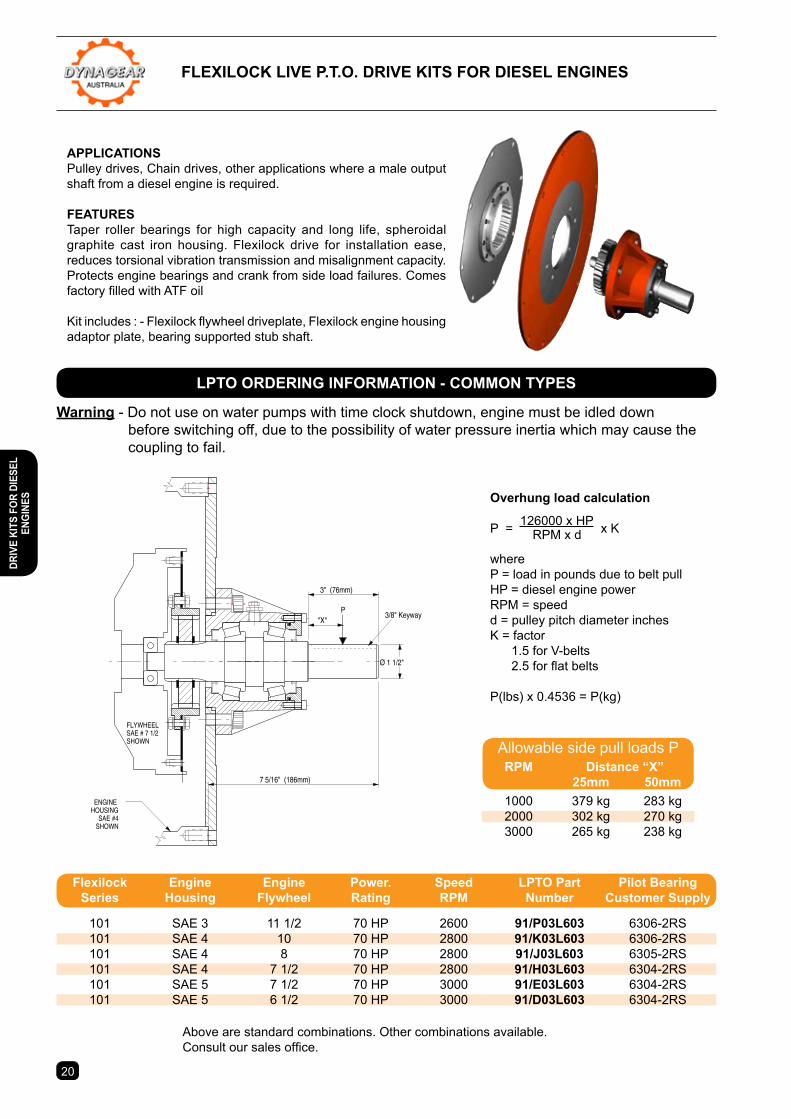
Overhung load calculation
P = 126000 x HP x K
RPM x d
whereP = load in pounds due to belt pullHP = diesel engine powerRPM = speedd = pulley pitch diameter inchesK = factor 1.5 for V-belts 2.5 for flat belts
P(lbs) x 0.4536 = P(kg)
APPLIcAtIonsPulley drives, Chain drives, other applications where a male output shaft from a diesel engine is required.
FeAtUResTaper roller bearings for high capacity and long life, spheroidal graphite cast iron housing. Flexilock drive for installation ease, reduces torsional vibration transmission and misalignment capacity. Protects engine bearings and crank from side load failures. Comes factory filled with ATF oil
Kit includes : - Flexilock flywheel driveplate, Flexilock engine housing adaptor plate, bearing supported stub shaft.
Above are standard combinations. Other combinations available.Consult our sales office.
3" (76mm)
Ø 1 1/2"
7 5/16" (186mm)
FLYWHEELSAE # 7 1/2SHOWN
ENGINEHOUSING
SAE #4SHOWN
P"X"
3/8" Keyway
Allowable side pull loads P
Warning - Do not use on water pumps with time clock shutdown, engine must be idled down before switching off, due to the possibility of water pressure inertia which may cause the coupling to fail.
FLeXILocK LIVe P.t.o. DRIVe KIts FoR DIeseL enGInes
LPto oRDeRInG InFoRMAtIon - coMMon tYPes
RPM Distance “X” 25mm 50mm 1000 379 kg 283 kg 2000 302 kg 270 kg 3000 265 kg 238 kg
Flexilock engine engine Power. speed LPto Part Pilot Bearing series Housing Flywheel Rating RPM number customer supply
101 SAE 3 11 1/2 70 HP 2600 91/P03L603 6306-2RS 101 SAE 4 10 70 HP 2800 91/K03L603 6306-2RS 101 SAE 4 8 70 HP 2800 91/J03L603 6305-2RS 101 SAE 4 7 1/2 70 HP 2800 91/H03L603 6304-2RS 101 SAE 5 7 1/2 70 HP 3000 91/e03L603 6304-2RS 101 SAE 5 6 1/2 70 HP 3000 91/D03L603 6304-2RS
DRIV
e KI
ts F
oR D
Iese
L en
GIne
s
21
SPEED (RPM)
OVE
RH
UN
G L
OAD
(kg)
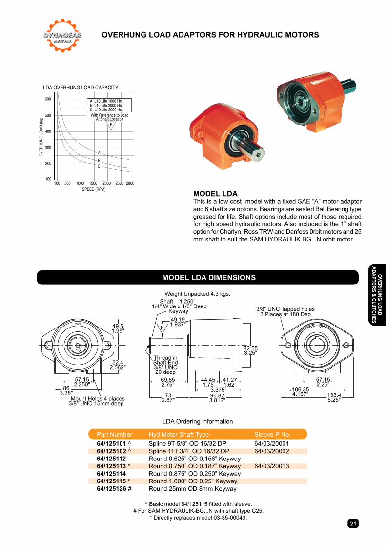
LDA OVERHUNG LOAD CAPACITY
1000100 2000 2800500 1500 2500
A. L10 Life 1000 HrsB. L10 Life 2000 HrsC. L10 Life 3000 Hrs
F
600
500
400
300
200
100
With Reference to LoadAt Shaft Location
CB
A
Mount Holes 4 places3/8" UNC 15mm deep
03827
2.747"2.749"
3/8" UNC Tapped holes2 Places at 180 Deg
Shaft ¯ 1.250" 1/4" Wide x 1/8" Deep
Keyway
Thread inShaft End3/8" UNC20 deep
15
F
MODEL LDAWeight Unpacked 4.3 kgs.
863.38"
57.152.250"
49.51.95"
52.42.062"
49.191.937"
69.852.75"
44.451.75
41.271.62"
732.87"
96.823.812"
3.375"
82.553.25"
106.354.187" 133.4
5.25"
57.152.25"
MoDeL LDA This is a low cost model with a fixed SAE “A” motor adaptor and 6 shaft size options. Bearings are sealed Ball Bearing type greased for life. Shaft options include most of those required for high speed hydraulic motors. Also included is the 1” shaft option for Charlyn, Ross TRW and Danfoss 0rbit motors and 25 mm shaft to suit the SAM HYDRAULIK BG...N orbit motor.
LDA Ordering information
^ Basic model 64/125115 fitted with sleeve.# For SAM HYDRAULIK-BG...N with shaft type C25.
* Directly replaces model 03-35-00043.
oVeRHUnG LoAD ADAPtoRs FoR HYDRAULIc MotoRs
MoDeL LDA DIMensIons
Part Number Hyd Motor Shaft Type Sleeve P No. 64/125101 ^ Spline 9T 5/8” OD 16/32 DP 64/03/20001 64/125102 ^ Spline 11T 3/4” OD 16/32 DP 64/03/20002 64/125112 Round 0.625” OD 0.156” Keyway 64/125113 ^ Round 0.750” OD 0.187” Keyway 64/03/20013 64/125114 Round 0.875” OD 0.250” Keyway 64/125115 * Round 1.000” OD 0.25” Keyway 64/125126 # Round 25mm OD 8mm Keyway
oVeRHUnG LoAD ADAPtoRs & cLUtcHes
22
4 HOLES 1/2" UNC25.4 DEEP ON A5" PCD (SAE B 4 BOLT)
28.6 88.9
82.55
O38
.1
O10
1.55
PILO
T
85.7
2X
63.5
68.5 165.8
MEASUREMENT "X"SAE A = 49SAE B = 62SAE C = 74
WEIGHT UNPACKED = 14kg
F
34.92 9.47
SAE A = 132SAE B = 177SAE C = 214
KEYWAY3/8" WIDE x 3/16" DEEP
BREATHER
FILLER PLUG
SHAFT BOLT HOLE3/8" UNC x 20 DEEP
MOUNTING HOLES4 OFF - 1/2"-13 UNC22 DEEP
30.5SAE C FLANGEOUTLINE
SPEED (RPM)
OVE
RH
UN
G L
OAD
(kg)
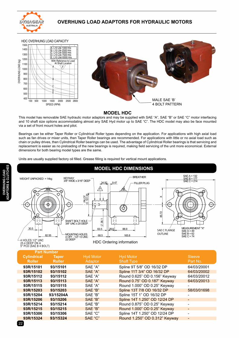
HDC OVERHUNG LOAD CAPACITY
1000100 2000 2800500 1500 2500
A. L10 Life 1000 HrsB. L10 Life 2500 HrsC. L10 Life 5000 HrsD. L10 Life 7500 HrsE. L10 Life10000 Hrs
F
1500
1400
1300
1200
1100
1000
900
800
700
600
500
400
With Reference to LoadAt Shaft Location
B
A
C
DE
MoDeL HDcThis model has removable SAE hydraulic motor adaptors and may be supplied with SAE “A”, SAE “B” or SAE “C” motor interfacing and 10 shaft size options accommodating almost any SAE Hyd motor up to SAE “C”. The HDC model may also be face mounted via a set of front mount holes and pilot.
Bearings can be either Taper Roller or Cylindrical Roller types depending on the application. For applications with high axial load such as fan drives or mixer units, then Taper Roller bearings are recommended. For applications with little or no axial load such as chain or pulley drives, then Cylindrical Roller bearings can be used. The advantage of Cylindrical Roller bearings is that servicing and replacement is easier as no preloading of the new bearings is required, making field servicing of the unit more economical. External dimensions for both bearing model types are the same.
Units are usually supplied factory oil filled. Grease filling is required for vertical mount applications.
HDC Ordering information
oVeRHUnG LoAD ADAPtoRs FoR HYDRAULIc MotoRs
MALE SAE ‘B’4 BOLT PATTERN
MoDeL HDc DIMensIons
Part number cylindrical taper Hyd Motor Hyd Motor Sleeve Roller Roller Adaptor Shaft Type Part No. 93R/15101 93/15101 SAE “A” Spline 9T 5/8” OD 16/32 DP 64/03/20001 93R/15102 93/15102 SAE “A” Spline 11T 3/4” OD 16/32 DP 64/03/20002 93R/15112 93/15112 SAE “A” Round 0.625” OD 0.156” Keyway 64/03/20012 93R/15113 93/15113 SAE “A” Round 0.75” OD 0.187” Keyway 64/03/20013 93R/15115 93/15115 SAE “A” Round 1.000” OD 0.25” Keyway - 93R/15203 93/15203 SAE “B” Spline 13T 7/8 OD 16/32 DP 58/03/01698 93R/15204 93/15204A SAE “B” Spline 15T 1” OD 16/32 DP - 93R/15206 93/15206 SAE “B” Spline 14T 1.250” OD 12/24 DP - 93R/15214 93/15214 SAE “B” Round 0.875” OD 0.25” Keyway - 93R/15215 93/15215 SAE “B” Round 1.000” OD 0.25” Keyway - 93R/15306 93/15306 SAE “C” Spline 14T 1.250” OD 12/24 DP - 93R/15324 93/15324 SAE “C” Round 1.250” OD 0.312” Keyway -
oVeR
HUnG
LoA
D AD
APto
Rs &
cLU
tcHe
s
81 7
85.7
2X
215
114
149
MEASUREMENT "X"SAE A = 49SAE B = 62SAE C = 74
54 166
29 88.950.8
101.
55PI
LOT
O31
.75
9.52
MOUNTING HOLES4 OFF - 1/2"-13 UNC22 DEEP
SHAFT BOLT HOLE3/8" UNC x 20 DEEP
82.55
30.5
INPUT
4 HOLES 1/2" UNC25.4 DEEP ON A5" PCD (SAE B 4 BOLT)
KEYWAY5/16" W IDE x 5/32" DEEP
CLUTCHDISENGAGEDW ITH LEVERIN THIS POSITION
U JOINT COMPANIONFLANGE 84/F390024IS AVAILABLE TO FITINPUT SHAFT
C/WAC/W
SAE C FLANGEOUTLINE
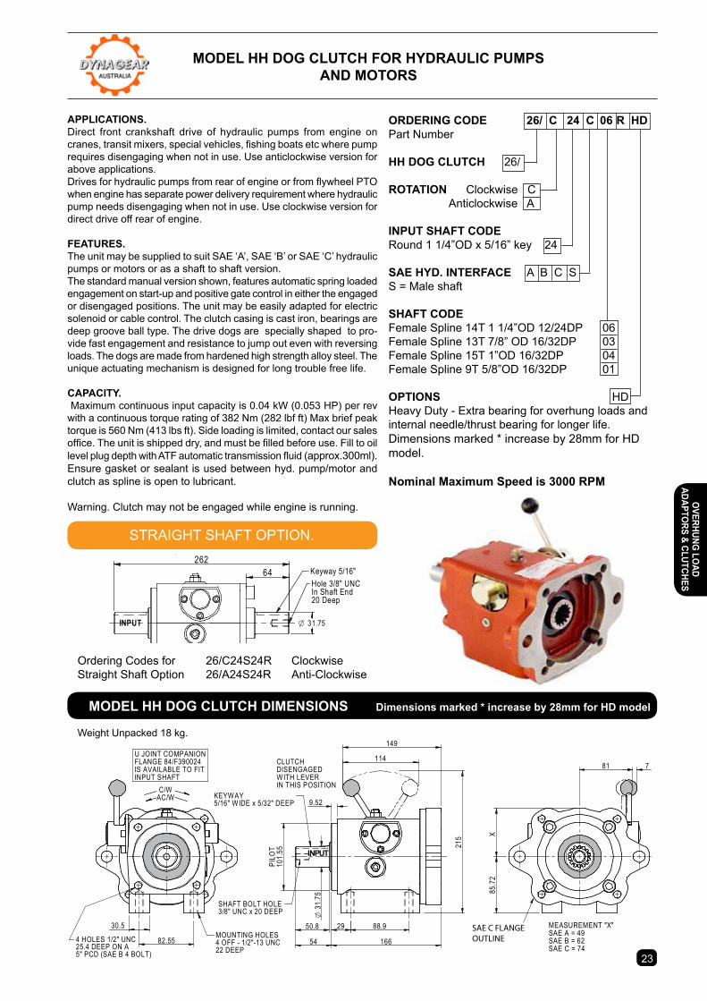
APPLIcAtIons. Direct front crankshaft drive of hydraulic pumps from engine on cranes, transit mixers, special vehicles, fishing boats etc where pump requires disengaging when not in use. Use anticlockwise version for above applications. Drives for hydraulic pumps from rear of engine or from flywheel PTO when engine has separate power delivery requirement where hydraulic pump needs disengaging when not in use. Use clockwise version for direct drive off rear of engine.
FeAtURes. The unit may be supplied to suit SAE ‘A’, SAE ‘B’ or SAE ‘C’ hydraulic pumps or motors or as a shaft to shaft version. The standard manual version shown, features automatic spring loaded engagement on start-up and positive gate control in either the engaged or disengaged positions. The unit may be easily adapted for electric solenoid or cable control. The clutch casing is cast iron, bearings are deep groove ball type. The drive dogs are specially shaped to pro-vide fast engagement and resistance to jump out even with reversing loads. The dogs are made from hardened high strength alloy steel. The unique actuating mechanism is designed for long trouble free life.
cAPAcItY. Maximum continuous input capacity is 0.04 kW (0.053 HP) per rev with a continuous torque rating of 382 Nm (282 lbf ft) Max brief peak torque is 560 Nm (413 lbs ft). Side loading is limited, contact our sales office. The unit is shipped dry, and must be filled before use. Fill to oil level plug depth with ATF automatic transmission fluid (approx.300ml). Ensure gasket or sealant is used between hyd. pump/motor and clutch as spline is open to lubricant.
Warning. Clutch may not be engaged while engine is running.
23
Weight Unpacked 18 kg.
MoDeL HH DoG cLUtcH FoR HYDRAULIc PUMPs AnD MotoRs
30.5
88.92954
50.8
166
215
149
9.52.375"
82.55
101.
55O
Pilo
t
Holes1/2" UNC4 Places22 Deep
4 Holes 1/2" UNC25.4 DeepOn A 5" PCD
114 781
X85
.72
C/WAC/W
Dimension X - SAE A = 49 (1.93")SAE B = 62 (2.44")SAE C = 74 (2.91")
Hole 3/8" UNCIn Shaft End20 Deep
Keyway 5/16"
ClutchDisengagedwith leverin thisposition
INPUT
SAE C
U Joint CompanionFlange 84/F390024
Is Available ToFit Input Shaft
64262
INPUT 31.75O
Keyway 5/16"Hole 3/8" UNCIn Shaft End20 Deep
oRDeRInG coDe 26/ c 24 c 06 R HD Part Number
HH DoG cLUtcH 26/
RotAtIon Clockwise C Anticlockwise A
InPUt sHAFt coDeRound 1 1/4”OD x 5/16” key 24
sAe HYD. InteRFAce A B C SS = Male shaft
sHAFt coDeFemale Spline 14T 1 1/4”OD 12/24DP 06Female Spline 13T 7/8” OD 16/32DP 03Female Spline 15T 1”OD 16/32DP 04Female Spline 9T 5/8”OD 16/32DP 01
oPtIons HDHeavy Duty - Extra bearing for overhung loads andinternal needle/thrust bearing for longer life. Dimensions marked * increase by 28mm for HD model.
nominal Maximum speed is 3000 RPM
Ordering Codes for 26/C24S24R ClockwiseStraight Shaft Option 26/A24S24R Anti-Clockwise
STRAIGHT SHAFT OPTION.
MoDeL HH DoG cLUtcH DIMensIons Dimensions marked * increase by 28mm for HD model
oVeRHUnG LoAD ADAPtoRs & cLUtcHes
2524
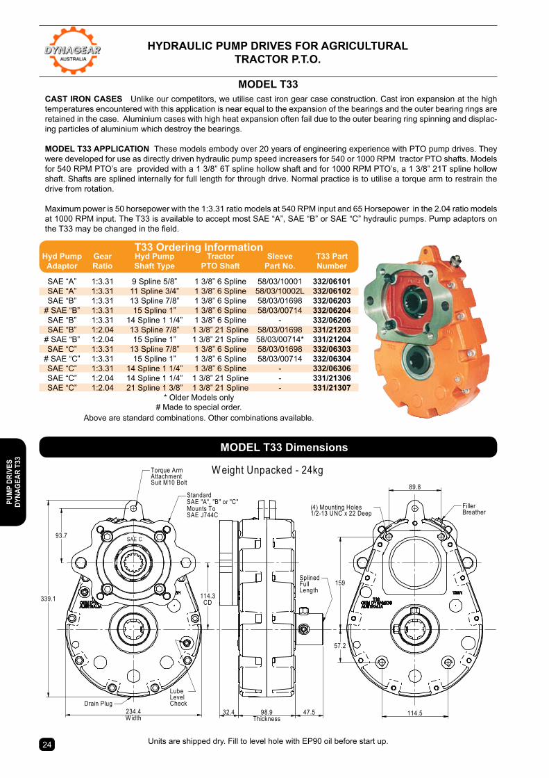
HYDRAULIc PUMP DRIVes FoR AGRIcULtURAL tRActoR P.t.o.
SAE C
W eight Unpacked - 24kg
339.1
93.7
Torque ArmAttachmentSuit M10 Bolt
234.4W idth
114.3CD
Drain Plug32.4 98.9
Thickness47.5
SplinedFullLength
FillerBreather
89.8
57.2
159
(4) Mounting Holes1/2-13 UNC x 22 Deep
StandardSAE "A", "B" or "C"Mounts ToSAE J744C
LubeLevelCheck
114.5
cAst IRon cAses Unlike our competitors, we utilise cast iron gear case construction. Cast iron expansion at the high temperatures encountered with this application is near equal to the expansion of the bearings and the outer bearing rings are retained in the case. Aluminium cases with high heat expansion often fail due to the outer bearing ring spinning and displac-ing particles of aluminium which destroy the bearings.
MoDeL t33 APPLIcAtIon These models embody over 20 years of engineering experience with PTO pump drives. They were developed for use as directly driven hydraulic pump speed increasers for 540 or 1000 RPM tractor PTO shafts. Models for 540 RPM PTO’s are provided with a 1 3/8” 6T spline hollow shaft and for 1000 RPM PTO’s, a 1 3/8” 21T spline hollow shaft. Shafts are splined internally for full length for through drive. Normal practice is to utilise a torque arm to restrain the drive from rotation.
Maximum power is 50 horsepower with the 1:3.31 ratio models at 540 RPM input and 65 Horsepower in the 2.04 ratio models at 1000 RPM input. The T33 is available to accept most SAE “A”, SAE “B” or SAE “C” hydraulic pumps. Pump adaptors on the T33 may be changed in the field.
MoDeL t33
Units are shipped dry. Fill to level hole with EP90 oil before start up.
MoDeL t33 Dimensions
t33 ordering Information Hyd Pump Gear Hyd Pump Tractor Sleeve T33 Part Adaptor Ratio shaft type Pto shaft Part no. number
SAE “A” 1:3.31 9 Spline 5/8” 1 3/8” 6 Spline 58/03/10001 332/06101 SAE “A” 1:3.31 11 Spline 3/4” 1 3/8” 6 Spline 58/03/10002L 332/06102 SAE “B” 1:3.31 13 Spline 7/8” 1 3/8” 6 Spline 58/03/01698 332/06203 # SAE “B” 1:3.31 15 Spline 1” 1 3/8” 6 Spline 58/03/00714 332/06204 SAE “B” 1:3.31 14 Spline 1 1/4” 1 3/8” 6 Spline - 332/06206 SAE “B” 1:2.04 13 Spline 7/8” 1 3/8” 21 Spline 58/03/01698 331/21203 # SAE “B” 1:2.04 15 Spline 1” 1 3/8” 21 Spline 58/03/00714* 331/21204 SAE “C” 1:3.31 13 Spline 7/8” 1 3/8” 6 Spline 58/03/01698 332/06303 # SAE “C” 1:3.31 15 Spline 1” 1 3/8” 6 Spline 58/03/00714 332/06304 SAE “C” 1:3.31 14 Spline 1 1/4” 1 3/8” 6 Spline - 332/06306 SAE “C” 1:2.04 14 Spline 1 1/4” 1 3/8” 21 Spline - 331/21306 SAE “C” 1:2.04 21 Spline 1 3/8” 1 3/8” 21 Spline - 331/21307 * Older Models only
# Made to special order. Above are standard combinations. Other combinations available.
PUM
P DR
IVes
DY
nAGe
AR t
33

2524
HYDRAULIc PUMP DRIVes FoR AGRIcULtURAL IMPLeMent MoUntInG
PARts AVAILABILItY The drives have been designed in Australia and are manufactured at our facility in Ballina N.S.W. Customers can obtain parts and service without delay. Technical assistance is available from the people who designed the product.
MoDeL t33I APPLIcAtIon This model was developed for use as an implement mounted hydraulic pump speed increaser for 1000 or 540 rpm tractor PTOs where thrust loads from PTO shafts are encountered. Tapped mounting holes are provided or a factory fitted base mounting bracket can be supplied.
Maximum power is 50 horsepower with the 1:3.31 ratio models at 540 rpm input and 65 Horsepower with the 1:2.04 ratio models at 1000 rpm input. The T33I male shaft input model is available to accept most SAE “A”, SAE “B” or SAE “C” hydraulic pumps. Pump adaptors on the T33I may be changed in the field. The T33I male shaft input & output model is supplied with a Ø1 1/2” x 3/8” keyed output shaft.
Optional male output shaft arrangement available on T33 & T33i models.
MoDeL t33I
32.4 98.9Thickness
90
SHAFT O1.5"3/8" Keyway x 3/16" Deep
9098.9Thickness
88.9
70
MoDeL t33I MALe sHAFt InPUt MALe InPUt & oUtPUt DIMensIons
t33I ordering Information Hyd Pump Gear Hyd Pump T33I Sleeve T33I Part Adaptor Ratio shaft type shaft Part no. number
SAE “A” 1:3.31 9 Spline 5/8” 1 3/8” 6 Spline 58/03/10001 332I/06101 SAE “A” 1:3.31 11 Spline 3/4” 1 3/8” 6 Spline 58/03/10002L 332I/06102 SAE “B” 1:3.31 13 Spline 7/8” 1 3/8” 6 Spline 58/03/01698 332I/06203 # SAE “B” 1:3.31 15 Spline 1” 1 3/8” 6 Spline 58/03/00714 332I/06204 # SAE “C” 1:3.31 15 Spline 1” 1 3/8” 6 Spline 58/03/00714 332I/06304 SAE “C” 1:3.31 14 Spline 1 1/4” 1 3/8” 6 Spline - 332I/06306 SAE “B” 1:2.04 13 Spline 7/8” 1 3/8” 21 Spline 58/03/01698 331I/21203 # SAE “B” 1:2.04 15 Spline 1” 1 3/8” 21 Spline 58/03/00714* 331I/21204 SAE “C” 1:2.04 14 Spline 1 1/4” 1 3/8” 21 Spline - 331I/21306
t33I ordering Information - Male shaft input & output 1:2.04 1 1/2” x 3/8” key 1 3/8” 21 Spline - 331I/21M60 1:3.31 1 1/2” x 3/8” key 1 3/8” 6 Spline - 332I/06M60
* Older Models only# Made to special order.
Above are standard combinations. Other combinations available.
PUMP DRIVes
DYnAGeAR t33
Units are shipped dry. Fill to level hole with EP90 oil before start up.
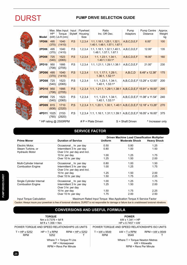
DURST PUMP DRIVe seLectIon GUIDe
seRVIce FActoR
conVeRsIons AnD UseFUL FoRMULA
Max. Max Input Input Flywheel Ratio Pump Pump Centre Approx. HP* Torque Style# Housing Inc. OR Dec. Adaptors Distance WeightModel (kW) Lb.ft (nm) Size kg
1PD06 495 1040 P,S 1,2,3,4 1:1, 1.18:1, 1.25:1, 1.32:1, A,B,C,D,E,F 6.00” 100 (370) (1410) 1.40:1, 1.48:1, 1.57:1, 1.67:1
2PD06 495 1040 P,S 1,2,3,4 1:1, 1.18:1, 1.32:1,1.40:1, A,B,C,D,E,F 12.00” 135 (370) (1410) 1.48:1, 1.57:1, 1.67:1
2PD08 725 1523 P,S 1,2,3,4 1:1, 1.23:1, 1.34:1, A,B,C,D,E,F 16.00” 160 (540) (2065) 1.40:1,1.53:1^
2PD10 950 1995 P,S 1,2,3,4 1:1, 1.21:1, 1.29:1,1.38:1 A,B,C,D,E,F 21.00” 230 (708) (2705)3PD06 495 1040 P,S 1,2,3,4 1:1, 1.17:1, 1.29:1, A,B,C,D 8.49” x 12.38” 175 (370) (1410) 1.36:1, 1.52:1^
3PD08 725 1523 P,S 1,2,3,4 1:1, 1.23:1, 1.34:1, A,B,C,D,E,F 13.29” x 12.00” 200 (540) (2065) 1.40:1, 1.53:1^
3PD10 950 1995 P,S 1,2,3,4 1:1, 1.21:1, 1.29:1,1.38:1 A,B,C,D,E,F 15.91” x 18.00” 295 (708) (2705)
4PD08 725 1523 P,S 1,2,3,4 1:1, 1.23:1, 1.34:1, A,B,C,D,E,F 11.08” x 11.54” 240 (540) (2065) 1.40:1, 1.53:1^
4PD09 815 1710 P,S 1,2,3,4 1:1, 1.20:1, 1.30:1, 1.40:1 A,B,C,D,E,F 12.18” x 13.26” 270 (608) (2320)
4PD11 1025 2153 P,S 1,2,3,4 1:1, 1.16:1, 1.31:1,1.39:1 A,B,C,D,E,F 16.05” x 16.00” 375 (765) (2920)
* HP rating @ 2500RPM # P = Plate Driven S = Shaft Driven ^ Increaser only
Driven Machine Load Classification Multiplier Prime Mover Duration of Service Uniform Moderate Shock Heavy Shock
Electric Motor, Occasional _ hr. per day 0.50 0.80 1.25 Steam Turbine, or Intermittent 3 hr. per day 0.80 1.00 1.50 Hydraulic Motor Over 3 hr. per day and incl. 10 hr. per day 1.00 1.25 1.75 Over 10 hr. per day 1.25 1.50 2.00
Multi-Cylinder Internal Occasional _ hr. per day 0.80 1.00 1.50 Combustion Engine Intermittent 3 hr. per day 1.00 1.25 1.75 Over 3 hr. per day and incl. 10 hr. per day 1.25 1.50 2.00 Over 10 hr. per day 1.50 1.75 2.25
Single Cylinder Internal Occasional _ hr. per day 1.00 1.25 1.75 Combustion Engine Intermittent 3 hr. per day 1.25 1.50 2.00 Over 3 hr. per day 10 hr. per day 1.50 1.75 2.25 Over 10 hr. per day 1.75 2.00 2.50
Input Torque Calculation Maximum Rated Input Torque Max Application Torque X Service Factor
TORQUE Nm x 0.7376 = lbf ft lbf ft x 1.356 = Nm
PoWeR kW x 1.341 = HP HP x 0.7457 = kW
POWER TORQUE AND SPEED RELATIONSHIPS US UNITS
T = HP x 5252 HP = T x RPM RPM = HP x 5252 RPM 5252 T
Where T = Torque Ft Lbs HP = Horsepower RPM = Revs Per Minute
Caution: Always insure your powertrain is free of torsional vibrations. DURST is not responsible for damage or failure due to unaddressed torsional vibrations
POWER TORQUE AND SPEED RELATIONSHIPS ISO UNITS
T = kW x 9549 kW = T x RPM RPM = kW x 9549 RPM 9549 T
Where T = Torque Newton Metres kW = Kilowatts RPM = Revs Per Minute
2726
PUM
P DR
IVes
DUR
st
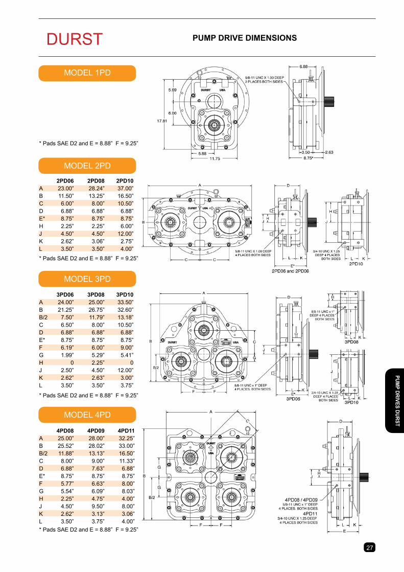
DURST PUMP DRIVe DIMensIons
MODEL 1PD
MODEL 2PD
MODEL 3PD
MODEL 4PD
* Pads SAE D2 and E = 8.88” F = 9.25”
* Pads SAE D2 and E = 8.88” F = 9.25”
* Pads SAE D2 and E = 8.88” F = 9.25”
* Pads SAE D2 and E = 8.88” F = 9.25”
2928
2PD06 2PD08 2PD10A 23.00” 28.24” 37.00”B 11.50” 13.25” 16.50”C 6.00” 8.00” 10.50”D 6.88” 6.88” 6.88”E* 8.75” 8.75” 8.75”H 2.25” 2.25” 6.00”J 4.50” 4.50” 12.00”K 2.62” 3.06” 2.75”L 3.50” 3.50” 4.00”
3PD06 3PD08 3PD10A 24.00” 25.00” 33.50”B 21.25” 26.75” 32.60”B/2 7.50” 11.79” 13.18”C 6.50” 8.00” 10.50”D 6.88” 6.88” 6.88”E* 8.75” 8.75” 8.75”F 6.19” 6.00” 9.00”G 1.99” 5.29” 5.41”H 0 2.25” 0J 2.50” 4.50” 12.00”K 2.62” 2.63” 3.00”L 3.50” 3.50” 3.75”
4PD08 4PD09 4PD11A 25.00” 28.00” 32.25”B 25.52” 28.02” 33.00”B/2 11.88” 13.13” 16.50”C 8.00” 9.00” 11.33”D 6.88” 7.63” 6.88”E* 8.75” 8.75” 8.75”F 5.77” 6.63” 8.00”G 5.54” 6.09” 8.03”H 2.25” 4.75” 4.00”J 4.50” 9.50” 8.00”K 2.62” 3.13” 3.06”L 3.50” 3.75” 4.00”
2726
PUMP DRIVes DURst
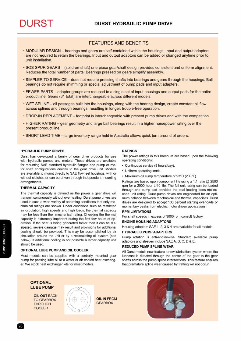
DURST
FEATURES AND BENEFITS • MODULAR DESIGN – bearings and gears are self-contained within the housings. Input and output adaptors
are not required to retain the bearings. Input and output adaptors can be added or changed anytime prior to unit installation.
• SOS SPUR GEARS – (solid-on-shaft) one-piece gear/shaft design provides consistent and uniform alignment. Reduces the total number of parts. Bearings pressed on gears simplify assembly.
• SIMPLER TO SERVICE – does not require pressing shafts into bearings and gears through the housings. Ball bearings do not require shimming or special adjustment of pump pads and input adapters.
• FEWER PARTS – adapter groups are reduced to a single set of input housings and output pads for the entire product line. Gears (31 total) are interchangeable across different models.
• WET SPLINE – oil passages built into the housings, along with the bearing design, create constant oil flow across splines and through bearings, resulting in longer, trouble-free operation.
• DROP-IN REPLACEMENT – footprint is interchangeable with present pump drives and with the competition.
• HIGHER RATING – gear geometry and large ball bearings result in a higher horsepower rating over the present product line.
• SHORT LEAD TIME – large inventory range held in Australia allows quick turn around of orders.
HYDRAULIc PUMP DRIVesDurst has developed a family of gear drive products for use with hydraulic pumps and motors. These drives are available for mounting SAE standard hydraulic flanges and pump or mo-tor shaft configurations directly to the gear drive unit. Models are available to mount directly to SAE flywheel housings, with or without clutches or can be driven through independent mounting arrangements.
tHeRMAL cAPAcItYThe thermal capacity is defined as the power a gear drive will transmit continuously without overheating. Durst pump drives are used in such a wide variety of operating conditions that only me-chanical ratings are shown. Under conditions such as restricted air circulation, high speeds and high loads, the thermal capacity may be less than the mechanical rating. Checking the thermal capacity is extremely important during the first few hours of op-eration. If the heat is being generated faster than it can be dis-sipated, severe damage may result and provisions for additional cooling should be provided. This may be accomplished by air circulation around the unit or by a recirculating oil system (see below). If additional cooling is not possible a larger capacity unit should be used.
oPtIonAL LUBe PUMP AnD oIL cooLeR. Most models can be supplied with a centrally mounted gear pump for passing lube oil to a water or air cooled heat exchang-er. We stock heat exchanger kits for most models.
RAtInGsThe power ratings in this brochure are based upon the following operating conditions:• Continuous service (8 hours/day).• Uniform operating loads.• Maximum oil sump temperature of 93°C (200°F).Ratings are based upon component life using a 1:1 ratio @ 2500 rpm for a 2000 hour L-10 life. The full unit rating can be loaded through one pump pad provided the total loading does not ex-ceed unit rating. Durst pump drives are engineered for an opti-mum balance between mechanical and thermal capacities. Durst drives are designed to accept 100 percent starting overloads or momentary peaks from electric motor driven applications.RPM LIMItAtIonsFor shaft speeds in excess of 3000 rpm consult factory.enGIne HoUsInG ADAPtoRsHousing adaptors SAE 1, 2, 3 & 4 are available for all models.HYDRAULIc PUMP ADAPtoRsPump rotation is anti-enginewise. Standard available pump adaptors and sleeves include SAE A, B, C, D & E. ReDUceD PUMP sPLIne WeARAll Durst models now feature a new lubrication system where the lubricant is directed through the centre of the gear to the gear shafts across the pump spline intersections. This feature ensures that premature spline wear caused by fretting will not occur.
oIL In FROM GEARBOX
oIL oUt BACK TO GEARBOX THROUGH COOLER
oPtIonAL LUBe PUMP
DURst HYDRAULIc PUMP DRIVe
2928
PUM
P DR
IVes
DUR
st
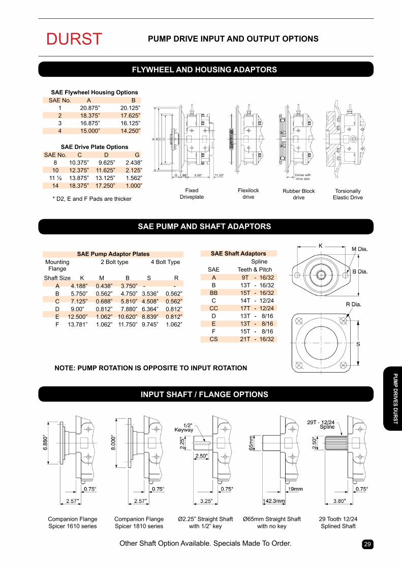
DURST
2928
PUMP DRIVe InPUt AnD oUtPUt oPtIons
FLYWHeeL AnD HoUsInG ADAPtoRs
InPUt sHAFt / FLAnGe oPtIons
sAe PUMP AnD sHAFt ADAPtoRs
* D2, E and F Pads are thickerFixed
DriveplateFlexilock
driveRubber Block
drive
Companion Flange Spicer 1610 series
Companion Flange Spicer 1810 series
Ø2.25” Straight Shaft with 1/2” key
Ø65mm Straight Shaft with no key
29 Tooth 12/24 Splined Shaft
Other Shaft Option Available. Specials Made To Order.
Torsionally Elastic Drive
sAe Flywheel Housing options SAE No. A B 1 20.875” 20.125” 2 18.375” 17.625” 3 16.875” 16.125” 4 15.000” 14.250”
SAE Drive Plate Options SAE No. C D G 8 10.375” 9.625” 2.438” 10 12.375” 11.625” 2.125” 11 ½ 13.875” 13.125” 1.562” 14 18.375” 17.250” 1.000”
sAe Pump Adaptor Plates Mounting 2 Bolt type 4 Bolt Type Flange Shaft Size K M B S R A 4.188” 0.438” 3.750” - - B 5.750” 0.562” 4.750” 3.536” 0.562” C 7.125” 0.688” 5.810” 4.508” 0.562” D 9.00” 0.812” 7.880” 6.364” 0.812” E 12.500” 1.062” 10.620” 8.839” 0.812” F 13.781” 1.062” 11.750” 9.745” 1.062”
sAe shaft Adaptors Spline SAE Teeth & Pitch A 9T - 16/32 B 13T - 16/32 BB 15T - 16/32 C 14T - 12/24 CC 17T - 12/24 D 13T - 8/16 E 13T - 8/16 F 15T - 8/16 CS 21T - 16/32
PUMP DRIVes DURst
note: PUMP RotAtIon Is oPPosIte to InPUt RotAtIon

DURST enGIneeReD sPecIALs
OEM Dynamics stock an extensive range of Durst Next Generation Hydraulic Pump Drives, while also offering Custom Engineered Solutions to compliment standard Durst Pump Drive unit configurations. Whether you need to mount a non-SAE standard hydraulic pump, fit special input/output shafts or couplings, fit hydraulic pumps or shafts on either side of the Pump Drive Unit or install a recirculating lubrication pump, filter and oil cooler, we can help. From the smallest modification to a complete system, we can analyse, improve, and design it using the latest computer-assisted design hardware. Our experienced in-house mechanical engineering, design and manufacturing team utilize CAD, 3D Engineering Modelling and Finite Element Analysis (FEA) programs.
Some examples of the custom designed and built Durst Hydraulic Pump Drive projects that have been carried out at our Ballina NSW facility include:
This drive is a custom designed and built Durst Model 3PD10 Triple Pump Drive unit OEM Dynamics re-engineered to fit a Bosch Rexroth A4CSG500 Hydraulic Pump for a Dredging Machine application. It has a 405mm diameter, 8 Bolt mounting pad and 80mm diameter splined drive shaft, while the unit is also fitted with 1 x SAE-D Hydraulic Pump Pad with the 3rd Pump Pad being blanked off for possible future use. An Oil Recirculating Lubrication System comprising of a Pump, Oil Filter and Water Cooled Oil Cooler has also been fitted.
To find out more about OEM Dynamics Custom Engineering Solutions for Durst Hydraulic Pump Drives, contact our Customer Support Department located at our Ballina NSW office.
This drive is a custom designed and built Durst Model 2PD06 Double Pump Drive unit that OEM Dynamics re-engineered to allow the fitting of 2 x OEM Dynamics Model HH Dog Clutches with SAE-C Hydraulic Pump Mounting pads, which will allow each pump to be individually engaged and disengaged, while the unit has also been fitted with a Torsionally Resistant Input Drive Coupling for a Vehicle River Crossing Ferry application.
ENGINE INPUT SIDE
PUMP OUTPUT SIDE
The unit below (shown from both sides) is a custom designed and built Durst Model 5PD10 (Special) Five Pump Drive unit that OEM Dynamics designed and re-engineered using a standard Durst Model 3PD10 Triple Drive unit for a Dredging Machine application. It is fitted with a total of 5 x Hydraulic Pump Mounting Pads (1 x SAE-D and 2 x SAE-C Mounting Pads) while 2 x additional Output Ports have been blanked off for possible future use. There is also an Oil Recirculating Lubrication Pump, Oil Filter and Water Cooled Oil Cooler fitted. To complete this very unique unit, OEM Dynamics have also designed and fitted a Through Drive Shaft to drive a 75kW (100Hp) Centrifugal Water Pump.
FIVE PUMP GEARBOXwith through drive shaft
TWO PUMP GEARBOXWITH DOG CLUTCHES
THREE PUMP GEARBOX
3130
PUM
P DR
IVes
DUR
st
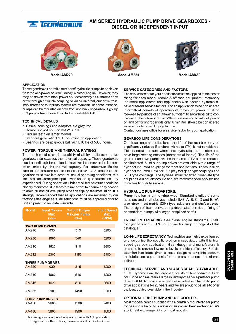
30
Model AM220 Model AM330 Model AM480
AM seRIes HYDRAULIc PUMP DRIVe GeARBoXes - DIeseL oR InDePenDent InPUt
seRVIce cAteGoRIes AnD FActoRsThe service factor for your application must be applied to the power rating for each model. Mobile & off road equipment , stationary industrial appliances and appliances with cooling systems all have different service factors. For an application to be considered intermittent periods of operation at maximum power must be followed by periods of shutdown sufficient to allow lube oil to cool to near ambient temperature. Where systems cycle with full power on and off for short periods only, 6 minutes should be considered as max continuous duty cycle time.Contact our sale office for a service factor for your application.
GeARBoX LIFe consIDeRAtIonsOn diesel engine applications, the life of the gearbox may be significantly reduced if torsional vibration (TV) is not considered. This is most relevant where the hydraulic pump elements have large rotating masses (moments of inertia). The life of the gearbox and hyd pumps will be increased if TV can be reduced or eliminated. All of our pump drives are available with a range of flywheel mounted couplings for most applications. These include flywheel mounted Flexilock 195 polymer gear type couplings and RBD type couplings. The flywheel mounted fixed driveplate type couplings will not absorb TV and are recommended only for use in mobile light duty service.
HYDRAULIc PUMP ADAPtoRs.Pump rotation is anti-engine wise. Standard available pump adaptors and shaft sleeves include SAE: A, B, C, D and E. We also stock most metric (DIN) type adaptors and shaft sleeves. The design of Technodrive pump drives also permits to fitting of nonstandard pumps with keyed or splined shafts.
enGIne InteRFAcInG. See diesel engine standards J620D for flywheels and J617C for engine housings on page 4 of this catalogue.
LonG LIFe eXPectAncY. Technodrive are highly experienced and recognise the specific problems associated with this high speed gearbox application. Gear design and manufacture is arranged to provide low noise levels and high efficiency. Special attention has been given to case design to take into account the lubrication requirements for the gears, bearings and internal splines.
tecHnIcAL seRVIce AnD sPARes ReADILY AVAILABLe. OEM Dynamics are the largest stockists of Technodrive outside of Europe and maintain a large inventory of service parts for pump drives. OEM Dynamics have been associated with hydraulic pump drive applications for 20 years and we are proud to be able to offer the best advice available in the industry.
oPtIonAL LUBe PUMP AnD oIL cooLeR. Most models can be supplied with a centrally mounted gear pump for passing lube oil to a water or air cooled heat exchanger. We stock heat exchanger kits for most models.
APPLIcAtIonThese gearboxes permit a number of hydraulic pumps to be driven from the one power source, usually, a diesel engine. However, they may be driven from most power sources directly as a shaft to shaft drive through a flexible coupling or via a universal joint drive train. Two, three and four pump models are available. In some instance, pumps can be mounted on both front and back of gearbox. Eg:- Up to 9 pumps have been fitted to the model AM450.
tecHnIcAL DetAILs• Cases, housings and adaptors are grey iron.• Gears: Shaved spur on AM 216/320. • Ground teeth on larger models • Standard gear ratio 1:1. Other ratios on application.• Bearings are deep groove ball with L10 life of 5000 hours.
POWER , TORQUE AND THERMAL RATINGSThe mechanical strength capability of all hydraulic pump drive gearboxes far exceeds their thermal capacity. These gearboxes can transmit high torque loads, however their service life is more often limited by the thermal capacity. For maximum life the lube oil temperature should not exceed 95 °C. Selection of the gearbox must take into account actual operating conditions, this includes considering the input power, speed, type of load and duty experienced. During operation lubricant oil temperature should be closely monitored, it is therefore important to ensure easy access to drain, fill and oil level plugs when designing the installation. It is strongly recommended that all applications are reviewed by our factory sales engineers. All selections must be approved prior to unit shipment to validate warranty.
Above figures are based on gearboxes with 1:1 gear ratios. For figures for other ratio’s, please consult our Sales Office. 3130
PUMP DRIVes
tecHnoDRIVe
Model Input torque output torque Input speed Max. Max.per Pump Max. (nm) (nm) (RPM)
tWo PUMP DRIVes AM216 630 315 3200
AM220 1080 540 3200
AM230 1620 810 2600
AM232 2300 1150 2400
tHRee PUMP DRIVes AM320 630 315 3200
AM330 1080 540 3200
AM345 1620 810 2600
AM365 2900 1450 2200
FoUR PUMP DRIVes AM450 2600 1300 2400
AM480 3800 1900 1800

4 Holes 7/16" UNC 3.75" (95.25) P.C.D.
Around 2.752" (69.9) Pilot
K
K
K
77
117.5
40û40û
31
T - varies from 15 to 75. Depends on pump
AM seRIes HYDRAULIc PUMP DRIVe GeARBoXes - DIeseL oR InDePenDent InPUt
GFH A
J
B
For AM450 - M12 x 16 PlacesFor AM480 - M20 x 24 Places
S
T
J
A/2
A/2
D
Rubber block type
Torques 860 to 3490 Nm
Fixed driveplatenot rated
Diesel Input 195 Flexilock
Max torque 969 Nm
U-joint companion
flange.
T - varies from 15 to 75. Depends on pump
FG T
H B A
M12all models
CD
J
S
G TH
ABF
S M12all models C
D
J
T - varies from 15 to 75. Depends on pump Weight - 217kg
MoDeL A B c D F G H J K s Wt kg
AM450 343.6 672 343.6 672 137.5 80 64 240 50 B62x57 DIN5482 205 AM480 437 900 437 900 156 96 108 400 100 B62x57 DIN5482 350
MODELS AM216, AM220, AM230 & AM232INPUT OPTIONS
MODELS AM320, AM330, AM345 & AM365
MODELS AM450 & AM480
MoDeL A B c D F G H J K s Wt kg
AM216 254 450 - 253 110 0 63.5 100 50 B48x44 DIN5482 40 AM220 299 570 86 360 129 30 63.5 165 50 B48x44 DIN5482 76 AM230 360 660 90 450 137.5 40 64 110 50 B62x57 DIN5482 103 AM232 460 800 - 430 137 40 64 110 50 B62x57 DIN5482 132
MoDeL A B c D F G H J K s Wt kg
AM320 220 450 190 447 110 0 63 100 50 B48x44 DIN5482 48 AM330 299 570 259 530 129 30 63.5 165 50 B48x44 DIN5482 139 AM345 360 660 291 630 137.5 40 64 110 50 B62x57 DIN5482 131 AM365 420 850 371 845 156 96 108 230 100 B62x57 DIN5482 215
3332
PUM
P DR
IVes
te
cHno
DRIV
e
TorsionallyElastic Coupling
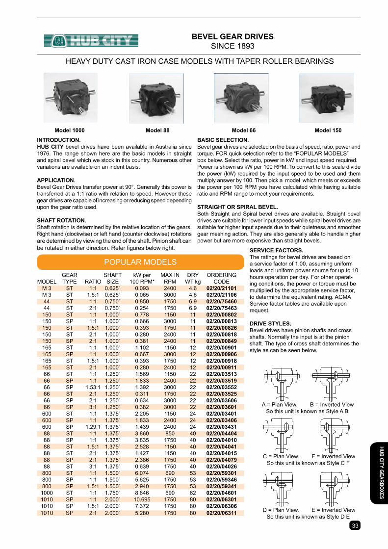
BAsIc seLectIon.Bevel gear drives are selected on the basis of speed, ratio, power and torque. FOR quick selection refer to the “POPULAR MODELS”box below. Select the ratio, power in kW and input speed required.Power is shown as kW per 100 RPM. To convert to this scale divide the power (kW) required by the input speed to be used and them multiply answer by 100. Then pick a model which meets or exceeds the power per 100 RPM you have calculated while having suitable ratio and RPM range to meet your requirements.
stRAIGHt oR sPIRAL BeVeL.Both Straight and Spiral bevel drives are available. Straight bevel drives are suitable for lower input speeds while spiral bevel drives are suitable for higher input speeds due to their quietness and smoother gear meshing action. They are also generally able to handle higher power but are more expensive than straight bevels.
32
Model 1000 Model 88 Model 66 Model 150
IntRoDUctIon. HUB cItY bevel drives have been available in Australia since 1976. The range shown here are the basic models in straight and spiral bevel which we stock in this country. Numerous other variations are available on an indent basis.
APPLIcAtIon. Bevel Gear Drives transfer power at 90°. Generally this power is transferred at a 1:1 ratio with relation to speed. However these gear drives are capable of increasing or reducing speed depending upon the gear ratio used.
sHAFt RotAtIon. Shaft rotation is determined by the relative location of the gears. Right hand (clockwise) or left hand (counter clockwise) rotations are determined by viewing the end of the shaft. Pinion shaft can be rotated in either direction. Refer figures below right.
HEAVY DUTY CAST IRON CASE MODELS WITH TAPER ROLLER BEARINGS
A = Plan View. B = Inverted ViewSo this unit is known as Style A B
C = Plan View. F = Inverted ViewSo this unit is known as Style C F
D = Plan View. E = Inverted ViewSo this unit is known as Style D E
BeVeL GeAR DRIVesSINCE 1893
POPULAR MODELSseRVIce FActoRs.The ratings for bevel drives are based on a service factor of 1.00, assuming uniform loads and uniform power source for up to 10 hours operation per day. For other operat-ing conditions, the power or torque must be multiplied by the appropriate service factor, to determine the equivalent rating. AGMA Service factor tables are available upon request.
DRIVe stYLes.Bevel drives have pinion shafts and cross shafts. Normally the input is at the pinion shaft. The type of cross shaft determines the style as can be seen below.
GEAR SHAFT kW per MAX IN DRY ORDERING MODEL TYPE RATIO SIZE 100 RPM* RPM WT kg CODE M 3 ST 1:1 0.625” 0.093 2400 4.6 02/20/21101 M 3 ST 1.5:1 0.625” 0.065 3000 4.6 02/20/21106 44 ST 1:1 0.750” 0.850 1750 6.9 02/20/75460 44 ST 2:1 0.750” 0.254 1750 6.9 02/20/75463 150 ST 1:1 1.000” 0.778 1150 11 02/20/00802 150 SP 1:1 1.000” 0.666 3000 11 02/20/00813 150 ST 1.5:1 1.000” 0.393 1750 11 02/20/00826 150 ST 2:1 1.000” 0.280 2400 11 02/20/00818 150 SP 2:1 1.000” 0.381 2400 11 02/20/00849 165 ST 1:1 1.000” 1.102 1150 12 02/20/00901 165 SP 1:1 1.000” 0.667 3000 12 02/20/00906 165 ST 1.5:1 1.000” 0.393 1750 12 02/20/00918 165 ST 2:1 1.000” 0.280 2400 12 02/20/00911 66 ST 1:1 1.250” 1.569 1150 22 02/20/03513 66 SP 1:1 1.250” 1.833 2400 22 02/20/03519 66 SP 1.53:1 1.250” 1.392 3000 22 02/20/03552 66 ST 2:1 1.250” 0.311 1750 22 02/20/03525 66 SP 2:1 1.250” 0.634 3000 22 02/20/03606 66 SP 3:1 1.250” 0.382 3000 22 02/20/03601 600 ST 1:1 1.375” 2.205 1150 24 02/20/03401 600 SP 1:1 1.375” 1.833 2400 24 02/20/03406 600 SP 1.29:1 1.375” 1.439 2400 24 02/20/03431 88 ST 1:1 1.375” 3.860 850 40 02/20/04404 88 SP 1:1 1.375” 3.835 1750 40 02/20/04010 88 ST 1.5:1 1.375” 2.528 1150 40 02/20/04041 88 ST 2:1 1.375” 1.427 1150 40 02/20/04015 88 SP 2:1 1.375” 2.386 1750 40 02/20/04079 88 ST 3:1 1.375” 0.639 1750 40 02/20/04026 800 ST 1:1 1.500” 6.074 690 53 02/20/59301 800 SP 1:1 1.500” 5.625 1750 53 02/20/59346 800 SP 1.5:1 1.500” 2.940 1750 53 02/20/59341 1000 ST 1:1 1.750” 8.646 690 62 02/20/04601 1010 SP 1:1 2.000” 10.695 1750 80 02/20/06301 1010 SP 1.5:1 2.000” 7.372 1750 80 02/20/06306 1010 SP 2:1 2.000” 5.280 1750 80 02/20/06311
3332
HUB cItY GeARBoXes
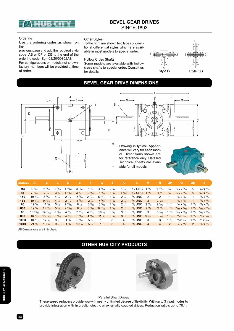
33
BeVeL GeAR DRIVesSINCE 1893
G
D
C
LS
Q
X
B
J
P
K
N
R
AE
MMJ
K
F
Drawing is typical. Appear-ance will vary for each mod-el. Dimensions shown are for reference only. Detailed Technical sheets are avail-able for all models.
Style G Style GG
A1 A2
A
B C
A
A1OrderingUse the ordering codes as shown on theprevious page and add the required style code AB or CF or DE to the end of the ordering code. Eg:- 02/20/00802ABFor configurations or models not shown, factory numbers will be provided at time of order.
Other StylesTo the right are shown two types of direc-tional differential styles which are avail-able in most models to special order.
Hollow Cross Shafts.Some models are available with hollow cross shafts to special order. Consult us for details.
Parallel Shaft DrivesThese speed reducers provide you with nearly unlimited degree of flexibility. With up to 3 input modes to provide integration with hydraulic, electric or externally coupled drives. Reduction ratio’s up to 70:1.
otHeR HUB cItY PRoDUcts
BeVeL GeAR DRIVe DIMensIons
MODEL A B C D E F G J K L M N ØP Q ØR S
M3 6 15/32 6 3/16 3 3/16 1 19/32 3 15/64 1 3/4 4 9/16 2 1/4 1 1/8 5/16 UNC 1 1/2 1 17/32 5/8 3/16 x 3/32 5/8 3/16 x 3/32
44 7 15/16 7 1/8 3 5/8 1 13/16 3 31/32 2 5/16 5 3/16 3 1/8 1 9/16 5/16 UNC 1 1/2 1 1/2 3/4 3/16 x 3/32 3/4 3/16 x 3/32
150 10 3/16 8 9/32 4 1/8 2 1/16 5 3/32 2 27/32 5 23/32 4 1/4 2 1/8 3/8 UNC 2 2 1 1/4 x 1/8 1 1/4 x 1/8
165 10 3/16 9 23/32 4 1/8 2 1/16 5 3/32 2 7/8 7 5/32 4 1/4 2 1/8 3/8 UNC 2 2 1/32 1 1/4 x 1/8 1 1/4 x 1/8
66 12 1/4 11 1/4 5 5/8 2 13/16 6 1/8 3 7/16 8 7/16 4 1/2 2 1/4 1/2 UNC 2 1/2 2 9/16 1 1/4 1/4 x 1/8 1 1/4 1/4 x 1/8
600 12 1/4 11 7/32 5 5/8 2 13/16 6 1/8 3 7/16 8 13/32 4 1/2 2 1/4 1/2 UNC 2 1/2 2 1/2 1 3/8 5/16 x 5/32 1 3/8 5/16 x 5/32
88 15 13/16 14 23/32 8 3/16 4 3/32 7 29/32 4 19/32 10 7/8 6 1/2 3 1/4 1/2 UNC 3 3 1/16 1 3/8 5/16 x 5/32 1 3/8 5/16 x 5/32
800 16 3/32 15 21/32 8 3/16 4 3/32 8 3/64 4 9/16 11 1/2 6 1/2 3 1/4 1/2 UNC 3 3/32 3 1/16 1 1/2 3/8 x 3/16 1 1/2 3/8 x 3/16
1000 18 9/32 17 3/4 9 1/2 4 3/4 9 9/64 5 1/4 13 8 4 1/2 UNC 3 3 1 3/4 3/8 x 3/16 1 3/4 3/8 x 3/16
1010 21 1/2 19 3/4 9 1/2 4 3/4 10 3/4 5 1/4 15 8 4 1/2 UNC 4 4 2 1/2 x 1/4 2 1/2 x 1/4
All Dimensions are in inches.
3534
HUB
cItY
GeA
RBoX
es
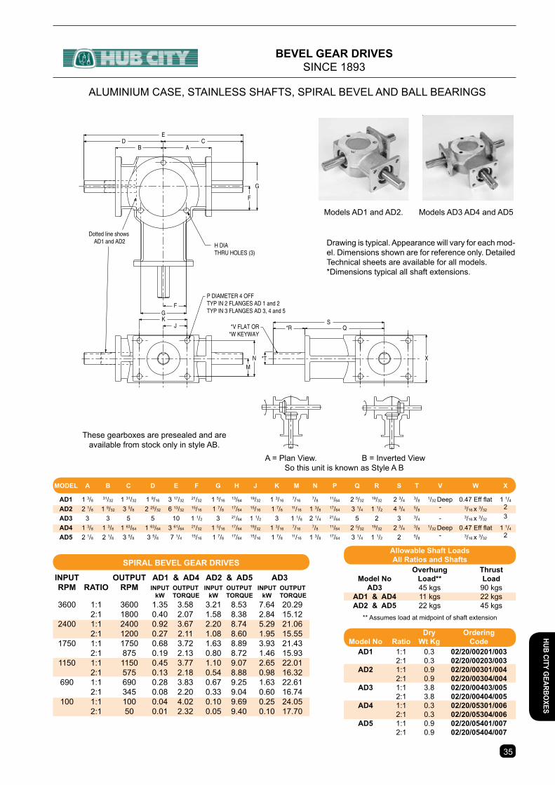
34
H DIATHRU HOLES (3)
Dotted line shows AD1 and AD2
NM
*T
*V FLAT OR*W KEYWAY
X
SQ*R
ED C
B A
G
F
GF
P DIAMETER 4 OFFTYP IN 2 FLANGES AD 1 and 2TYP IN 3 FLANGES AD 3, 4 and 5
KJ
Drawing is typical. Appearance will vary for each mod-el. Dimensions shown are for reference only. Detailed Technical sheets are available for all models.*Dimensions typical all shaft extensions.
** Assumes load at midpoint of shaft extension
ALUMINIUM CASE, STAINLESS SHAFTS, SPIRAL BEVEL AND BALL BEARINGS
These gearboxes are presealed and are available from stock only in style AB.
A = Plan View. B = Inverted ViewSo this unit is known as Style A B
Models AD1 and AD2. Models AD3 AD4 and AD5
BeVeL GeAR DRIVesSINCE 1893
sPIRAL BeVeL GeAR DRIVes
InPUt oUtPUt AD1 & AD4 AD2 & AD5 AD3 RPM RAtIo RPM InPUt oUtPUt InPUt oUtPUt InPUt oUtPUt kW TORQUE kW TORQUE kW TORQUE 3600 1:1 3600 1.35 3.58 3.21 8.53 7.64 20.29 2:1 1800 0.40 2.07 1.58 8.38 2.84 15.12 2400 1:1 2400 0.92 3.67 2.20 8.74 5.29 21.06 2:1 1200 0.27 2.11 1.08 8.60 1.95 15.55 1750 1:1 1750 0.68 3.72 1.63 8.89 3.93 21.43 2:1 875 0.19 2.13 0.80 8.72 1.46 15.93 1150 1:1 1150 0.45 3.77 1.10 9.07 2.65 22.01 2:1 575 0.13 2.18 0.54 8.88 0.98 16.32 690 1:1 690 0.28 3.83 0.67 9.25 1.63 22.61 2:1 345 0.08 2.20 0.33 9.04 0.60 16.74 100 1:1 100 0.04 4.02 0.10 9.69 0.25 24.05 2:1 50 0.01 2.32 0.05 9.40 0.10 17.70
Allowable shaft LoadsAll Ratios and shafts
Overhung Thrust Model no Load** Load AD3 45 kgs 90 kgs AD1 & AD4 11 kgs 22 kgs AD2 & AD5 22 kgs 45 kgs
Dry ordering Model no Ratio Wt Kg code AD1 1:1 0.3 02/20/00201/003 2:1 0.3 02/20/00203/003 AD2 1:1 0.9 02/20/00301/004 2:1 0.9 02/20/00304/004 AD3 1:1 3.8 02/20/00403/005 2:1 3.8 02/20/00404/005 AD4 1:1 0.3 02/20/05301/006 2:1 0.3 02/20/05304/006 AD5 1:1 0.9 02/20/05401/007 2:1 0.9 02/20/05404/007
MODEL A B C D E F G H J K M N P Q R S T V W X
AD1 1 3/8 31/32 1 31/32 1 9/16 3 17/32 21/32 1 5/16 13/64 19/32 1 3/16 7/16 7/8 11/64 2 5/32 19/32 2 3/4 3/8 1/32 Deep 0.47 Eff flat 1 1/4
AD2 2 1/8 1 9/32 3 5/8 2 25/32 6 13/32 15/16 1 7/8 17/64 15/16 1 7/8 11/16 1 3/8 17/64 3 1/4 1 1/2 4 3/4 5/8 - 3/16 x 3/32 2
AD3 3 3 5 5 10 1 1/2 3 21/64 1 1/2 3 1 1/8 2 1/4 21/64 5 2 3 3/4 - 3/16 x 3/32 3
AD4 1 3/8 1 3/8 1 63/64 1 63/64 3 61/64 21/32 1 5/16 17/64 19/32 1 3/16 7/16 7/8 11/64 2 5/32 19/32 2 3/4 3/8 1/32 Deep 0.47 Eff flat 1 1/4
AD5 2 1/8 2 1/8 3 5/8 3 5/8 7 1/4 15/16 1 7/8 17/64 15/16 1 7/8 11/16 1 3/8 17/64 3 1/4 1 1/2 2 5/8 - 3/16 x 3/32 2
3534
HUB cItY GeARBoXes
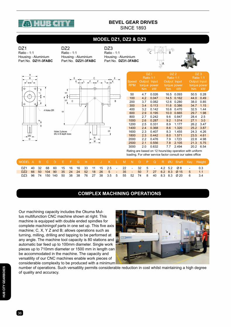
35
BI I
ØSO
4 Holes ØR
CF F KK LL
E E
Q
PJ
J
A
N
M
GG
D
E
¯30 55
L
19
Hollow Shaft Model - 3H
6mm Keyway
A
BC
Holes 3 placesØU in B depth boss
H
DZ2Ratio - 1:1Housing - AluminiumPart No. DZ21-3FABc
A
BCDZ1Ratio - 1:1Housing - AluminiumPart No. DZ11-3FABc
DZ3Ratio - 1:1Housing - AluminiumPart No. DZ31-3FABc
Rating are based on 12 hours/day operation with uniform loading. For other service factor consult our sales office
BeVeL GeAR DRIVesSINCE 1893
MoDeL DZ1, DZ2 & DZ3
DZ I DZ 2 DZ 3 Ratio 1:1 Ratio 1:1 Ratio 1:1 Speed Output Input Output Input Output Input RPM torque power torque power torque power Nm kW Nm kW Nm kW
50 4.7 0.026 16.5 0.093 50.5 0.28 100 4.2 0.047 14.5 0.162 44.0 0.49 200 3.7 0.082 12.6 0.280 38.0 0.85 300 3.4 0.113 11.6 0.386 34.7 1.15 400 3.2 0.142 10.6 0.470 32.5 1.44 600 2.9 0.195 10.0 0.665 29.7 1.98 800 2.7 0.242 9.6 0.847 28.4 2.5 1000 2.6 0.287 9.2 1.014 27.1 3.0 1200 2.5 0.331 8.9 1.177 26.2 3.47 1400 2.4 0.368 8.6 1.320 25.2 3.87 1600 2.3 0.407 8.3 1.455 24.3 4.26 1800 2.3 0.442 8.0 1.571 23.5 4.61 2000 2.2 0.476 7.9 I.723 22.8 4.98 2500 2.1 0.556 7.8 2.105 21.3 5.75 3000 2.0 0.632 7.7 2.494 20.2 6.54
MODEL A B C D E F G H I J K L M N O P Q R ØU Shaft Key Weight
DZ1 40 32 68 60 15 16 16 33 11 15 2.5 - 22 - 32 5 - 4.2 5.2 Ø 8 - 0.3 DZ2 66 50 104 90 35 24 24 52 18 26 5 - 35 - 50 7 27 6.2 8.3 Ø 15 5 1.1 DZ3 96 74 150 140 50 38 38 76 27 38 3.5 5 55 52 74 8 40 8.3 8.3 Ø 20 6 3.4
3736
HUB
cItY
GeA
RBoX
es
Our machining capacity includes the Okuma Mul-tus multifunction CNC machine shown at right. This machine is equipped with double ended spindles for complete machiningof parts in one set up. This five axis machine; C, X, Y Z and B; allows operations such as turning, milling, drilling and tapping to be performed at any angle. The machine tool capacity is 80 stations and automatic bar feed up to 100mm diameter. Single work pieces up to 710mm diameter or 1500 mm in length can be accommodated in the machine. The capacity and versatility of our CNC machines enable work pieces of considerable complexity to be produced with a minimum number of operations. Such versatility permits considerable reduction in cost whilst maintaining a high degree of quality and accuracy.
coMPLeX MAcHInInG oPeRAtIons

36
Heat Load Based on Temperature Rise Over Time ISO UNITS
Heat Load = = kW
Where t1 = Initial oil temp (°C) t2 = Final oil temp (°C) T = Time for temp rise (seconds) V = System oil volume (litres) Cp = Oil heat capacity (kJ/L°C) Cp=1.72 Typ for oil.
V x Cp x (t2-t1)T
∆ T °C = kW x K kW = L/min x ∆T °C L/min = kW x K L/min K ∆T °C Where L/min = Oil flow in Litres per minute ∆T °C = Entering temp of oil minus exit temp of oil. kW = Heat to be removed K = 34.5 for Oil K = 14.3 for Water K factors above are typical only and will vary with density and temperature of fluid.
Power, Heat and Flow Relationships. ISO UNITS
conVeRsIonsTORQUE
Nm x 0.7376 = lbf ftlbf ft x 1.356 = Nmlb in x 0.1130 = Nm kgm x 9.807 = Nm kgm x 7.232 = lbf ft
PoWeR kW x 1.341 = HPHP x 0.7457 = kW
Met HP x 0.7355 = kW Ton of Rfg x 3.517 = kW
PRessURePSI x 6.89 = kPa
PSI x 0.0689 = BarBar x 14.5 = PSI
inH2O x 0.249 = kPa
POWER TORQUE AND SPEED RELATIONSHIPS ISO UNITS
HYDRAULIC ( FLUID POWER) POWER ISO UNITSHYDRAULIC ( FLUID POWER) POWER US UNITS
POWER TORQUE AND SPEED RELATIONSHIPS US UNITS
T = HP x 5252 HP = T x RPM RPM = HP x 5252 RPM 5252 T Where T = Torque Ft Lbs HP = Horsepower RPM = Revs Per Minute
HP = PSI x US GPM PSI = Lbs per Sq Inch Pressure 1714 US GPM = Gallons Per Minute US Above is theoretical power. Add inefficiency.
kW = Bar x L/min Bar = Pressure Bar 600 L/min = Litres Per Minute Above is theoretical power. Add inefficiency.
T = kW x 9549 kW = T x RPM RPM = kW x 9549 RPM 9549 T Where T = Torque Newton Metres kW = Kilowatts RPM = Revs Per Minute
NO RESPONSIBILITY IS ACCEPTED FOR OMISSIONS VARIATIONS OR ERRORS
VoLUMeGal (UK) x 4.546 = LitresGal (US) x 3.785 = Litres
Cu Ft x 28.32 = Litres
LenGtHInch x 25.4 = mm
Feet x 0.3048 = metre
AReASq Inch x 6.452 = Sq cmSq Ft x 0.0929 = Sq mtr
VeLocItYFt/s x 0.3048 = m/s
mph x 1.609344 = km/hKnot UK x 1.853 = km/h
teMPeRAtURe°C x 1.8 + 32 = °F
MAssOz x 28.3495 = gram
lb x 0.4536 = kgTon UK x 1.016 = Tonne
VIscosItYSSU x4.6 = cSt
otHeRBTU/hr x 0.293 = W
Kilocalorie x 4.1868 = kJCFM x 0.000472 = m3/s
conVeRsIons AnD UseFUL FoRMULA
3736
cALcULAtIons &UseFUL FoRM
ULA
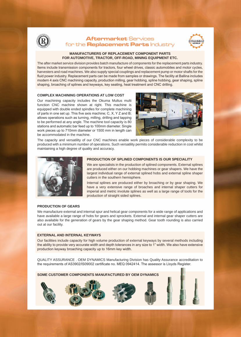
Aftermarket Servicesfor the Replacement Parts Industry
MANUFACTURERS OF REPLACEMENT COMPONENT PARTS FOR AUTOMOTIVE, TRACTOR, OFF-ROAD, MINING EQUIPMENT ETC.
The after market service division provides batch manufacture of components for the replacement parts industry. Items include transmission components for tractors, four wheel drives, classic automobiles and motor cycles, harvesters and road machines. We also supply special couplings and replacement pump or motor shafts for the fluid power industry. Replacement parts can be made from samples or drawings. The facility at Ballina includes modern 4 axis CNC machining capacity, production milling, gear hobbing, spline hobbing, gear shaping, spline shaping, broaching of splines and keyways, key seating, heat treatment and CNC drilling.
COMPLEX MACHINING OPERATIONS AT LOW COSTOur machining capacity includes the Okuma Multus multi function CNC machine shown at right. This machine is equipped with double ended spindles for complete machining of parts in one set up. This five axis machine; C, X, Y Z and B; allows operations such as turning, milling, drilling and tapping to be performed at any angle. The machine tool capacity is 80 stations and automatic bar feed up to 100mm diameter. Single work pieces up to 710mm diameter or 1500 mm in length can be accommodated in the machine.The capacity and versatility of our CNC machines enable work pieces of considerable complexity to be produced with a minimum number of operations. Such versatility permits considerable reduction in cost whilst maintaining a high degree of quality and accuracy.
PRODUCTION OF SPLINED COMPONENTS IS OUR SPECIALITYWe are specialists in the production of splined components. External splines are produced either on our hobbing machines or gear shapers. We have the largest individual range of external splined hobs and external spline shaper cutters in the southern hemisphere.Internal splines are produced either by broaching or by gear shaping. We have a very extensive range of broaches and internal shaper cutters for imperial and metric involute splines as well as a large range of tools for the production of straight sided splines.
PRODUCTION OF GEARSWe manufacture external and internal spur and helical gear components for a wide range of applications and have available a large range of hobs for gears and sprockets. External and internal gear shaper cutters are also available for the generation of gears by the gear shaping method. Gear tooth rounding is also carried out at our facility.
EXTERNAL AND INTERNAL KEYWAYSOur facilities include capacity for high volume production of external keyways by several methods including the ability to provide very accurate width and depth tolerances in any size to 1” width. We also have extensive production keyway broaching capacity up to 16mm key width.
QUALITY ASSURANCE . OEM DYNAMICS Manufacturing Division has Quality Assurance accreditation to the requirements of AS3902/lS09002 certificate no. MEQ 0942414. The assessor is Lloyds Register.
SOME CUSTOMER COMPONENTS MANUFACTURED BY OEM DYNAMICS
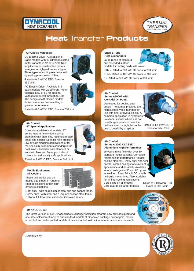
Air Cooled VersacoolDC Electric Drive - Available in 6 Basic models with 19 different electric motor variants in 12 or 24 Volt. New long life water resistant fan motors in regular orhigh performance types. Three types of cooling elements with operating pressure to 14 Bar. Rated to 0.5 kW/°C ETD, flows to 150 l/min.AC Electric Drive - Available in 6 basic models with 22 different motor variants in 50 or 60 Hz options. Voltages from 240 through to 450. The design of AC electric models delivers more air flow resulting in greater performance.Rated to 0.8 kW/°C ETD, flows to 200 l/min.
Shell & Tube Heat Exchangers
Large range of standard and extended surface models for cooling fluids with water.EKM - Rated to 200 kW. Oil flows to 200 l/minECM - Rated to 400 kW. Oil flows to 700 l/min.B - Rated to 370 kW. Oil flows to 960 l/min.
Air Cooled Series A2000P with Co-Axial Oil PumpDeveloped for cooling gear drives. The pumps provided are high suction types intended for use with gear or hydraulic oils. A common application in hydraulics is cylinder circuits where it is not usually appropriate to pass the on line circuit through the cooler due to possibility of spikes.
Air Cooled Series A 2000 CLASSIC Aluminium High Performance25 years in the field with over 30 standard model variants. Corrosion resistant high performance Albraze cooling element. Heavy duty zinc seal powder coated casings for excellent appearance and durability. Available in most voltages in 50 and 60 cycles as well as 12 and 24 volt DC or with hydraulic motor drive. Also available for air intercooling applications. Core skirts on all models. Core guards on larger models.
Air Cooled ST Special Application
Currently available in 4 models. ST series feature heavy duty cooling elements with steel fins, rectangular steel tanks and copper tubes for high pressure low air side clogging applications or for the special requirements of underground coal mines. Available with standard or antistatic fans and flame proof electric motors for intrinsically safe applications .Rated to 2 kW/°C ETD, flows to 540 L/min.
Mobile Equipment Oil Coolers
These unit are for use on mobile equipment in rough off road applications and in high pressure situations.Light duty - with aluminium or steel fins and copper tanks. Heavy duty - with steel fins & square section steel tanks. Optional full flow relief valves for improved safety.
DYNACOOL CDThe latest version of our Dynacool heat exchanger selection program now provides quick and accurate selection of most of our standard models of air cooled package exchangers, mobile air cooled and water cooled models. A new easy find instruction manual is now also available.
Distributed by:
Rated to 1.4 kW/°C ETD Flows to 125 L/min.
Rated to 9.0 kW/°C ETD Flows to 800 L/min.
Heat Transfer Products


![Bivariate B-spline Outline Multivariate B-spline [Neamtu 04] Computation of high order Voronoi diagram Interpolation with B-spline.](https://static.documents.pub/doc/80x56/56649d445503460f94a20e90/bivariate-b-spline-outline-multivariate-b-spline-neamtu-04-computation-of.jpg)