

The Cricket Indoor Location System
Hari Balakrishnan
Cricket Project MIT Computer Science and Artificial Intelligence Lab
http://nms.csail.mit.edu/~hari http://cricket.csail.mit.edu
Joint work with Bodhi Priyantha and others

Outline
• Some Cricket applications
• Cricket architecture
• Distance and location estimation
• Other features, status, demo

Cricket
A general-purpose indoor location system for mobile and sensor computing applications

Indoor Human/Robot Navigation
Cricket

Virtual/Physical Games
Rudolph et al., MIT Project Oxygen

Hospital Applications
Tracking patients and equipment in hospitals

Location-Aware Sensing • Networked sensors
enable remote monitoring and control – Asset tracking – Environmental
monitoring – Supply chain – Remote actuation
• Sensor streams need to be annotated with location
Temperature, light, sound sensors, buzzer
Outline
• Applications
• Cricket architecture
• Distance and location estimation
• Other features, status, demo

Location = Space, Position, Orientation
Room 3
• Space: Rooms, parts of rooms • Position: (x, y, z) coordinates • Orientation: Direction vector
(x,y,z)
θ
Room 1-N
Room 1-S

Design Goals
• Must work well indoors
• Must scale to large numbers of devices
• Should not violate user location privacy
• Must be easy to deploy and administer
• Should have low energy consumption

Cricket Architecture
Beacon
Listener
Passive listeners + active beacons scales well, helps preserve user privacy Decentralized, self-configuring network of autonomous beacons
info = “a1”
info = “a2”
Estimate distancesto infer location

Obtain linear distance estimates Pick nearest to infer “space” Solve for device’s (x, y, z) Determine θ w.r.t. each beacon and deduce orientation vector
SPACE = NE43-510COORD = (146 272 0)

• A beacon transmits an RF and an ultrasonic signal simultaneously – RF carries location data, ultrasound is a narrow
pulse
• The listener measures the time gap between the receipt of RF and ultrasonic (US) signals – Velocity of US << velocity of RF
Determining Distance
RF data(space name)
Beacon
Listener
Ultrasound(pulse)

Distance Measurement Performance
Distance accuracy experimental setup
θ
θ
d
• Error increases with d and θ – Signal gets weaker with increasing d and θ – Takes longer to detect at listener – Errors are on the order of US wavelength
0
5
10
15
20
-80 -60 -40 -20 0 20 40 60 80
Erro
r (cm
)
Angle (degrees)
2 m4 m6 m8 m
Beacon
Listener

Multiple Beacons Cause Complications
• Beacon transmissions are uncoordinated • Ultrasonic pulses reflect off walls These make the correlation problem hard and can
lead to incorrect distance estimates Solution: Beacon interference avoidance + listener
interference detection
Beacon A Beacon B
time RF B RF A US B US A
Incorrect distance
Listener
RF A US B US A
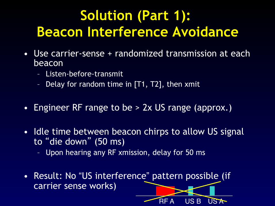
Solution (Part 1): Beacon Interference Avoidance
• Use carrier-sense + randomized transmission at each beacon – Listen-before-transmit – Delay for random time in [T1, T2], then xmit
• Engineer RF range to be > 2x US range (approx.)
• Idle time between beacon chirps to allow US signal to “die down” (50 ms) – Upon hearing any RF xmission, delay for 50 ms
• Result: No “US interference” pattern possible (if carrier sense works)

Solution (Part 2): Listener Interference Detection
• “RF interference” still possible
• Solution: Listener counts the number of RF messages during 50 ms before US signal – Only one RF? Then, accept – More than one? Then, reject
Accept50 ms
Reject50 ms
RF A US ARF B

Beacon Interference Detection/Avoidance Performance
0
0.5
1
1.5
0 5 10 15 20 25 30 35 40 45 50 55
% o
utlie
rs
Number of beacons
% outlier distance samples
• Outliers (>5% error) caused by: – RF vagaries: dead spots, fading, imperfect carrier
sensing – Ultrasonic noise: Jangling keys, faulty lights
• Hence, position estimators need to handle outliers
Listener
Beacons
3 m
3 m
2.28 m

Space Estimation • Static outlier detection: MinMode algorithm
• Find mode of each beacon’s measured distances over recent time window
• Space = beacon with smallest mode

Position Estimation • Static case is easy (lateration)
• Mobile case is harder
Samples Position estimate

Predict
Correct
State Prediction
Sample
Listener: Extended Kalman Filter
• Single-constraint-at-a-time Kalman filter (similar to Welch et al.)
• Handle non-Gaussian errors • Cope with bad state
• If prediction consistently bad, then reset by active chirp

Prototype
Cricket + environmental sensors
Ultrasonic sensors
Distance accuracy: 1-5 cm Position accuracy: 10-15 cm Orientation accuracy: 3-5 degrees Beacon power consumption: 1.5 mA @ 2.7 V Two AA batteries last 6-8 weeks Embedded software in TinyOS Commercially available
RS232
Radio
External sensor connector
Antenna conn. Atmel processor
MicrocontrollerAtmega 128L
AmplifierR
UltrasonicReceiver
AmplitudeDetector
Ultrasonic Driver (12V)
VoltageMultiplier
RS 232 Driver
RS 232 Connector
Vcc
3 V
T
UltrasonicTransmitter
418 MHz
Beacon / Listener
Mica Mote interface
RF Transceiver
−
+

Demo: Tracking a Moving Robot with Cricket

Other Features of Cricket
• Orientation – Listener ultrasound array for differential
distances
• Filtering and tracking algorithms
• Reducing energy consumption – Sleep/wakeup scheduling and hardware
optimizations
• Health monitoring and maintenance
• Location API

Conclusion • Key ideas in MobiCom 2000 paper
– Active beacons, passive listener – Notion of space as distinct from position – Distributed coordination – Handling noise in distance estimates
• Cricket provides location information for mobile & sensor computing applications – Accurate space, position, orientation – Designed for both handheld and sensor apps
• Passive mobile architecture is scalable and helps preserve user privacy
• Hardware commercially available; software open-source
http://cricket.csail.mit.edu/

Pose-Aware Applications
Software flashlight & marker
Teller et al., MIT Project Oxygen

Orientation relative to Bon horizontal plane
Mobile device(parallel to horizontal plane)
Beacons on ceiling
θ
B
Cricket listener withcompass hardware
Orientation

Orientation using Differential Distance
d1 d2 z
θ
sin θ = (d2 - d1) / sqrt (1 - z2/d2)where d = (d1+d2)/2
BeaconIdea: Use multiple ultrasonic sensors
and estimate differential distances
Two terms need to be estimated: 1. d2 – d1 2. z/d (by estimating coordinates)
Multiple sensors oncompass board
Use phase difference
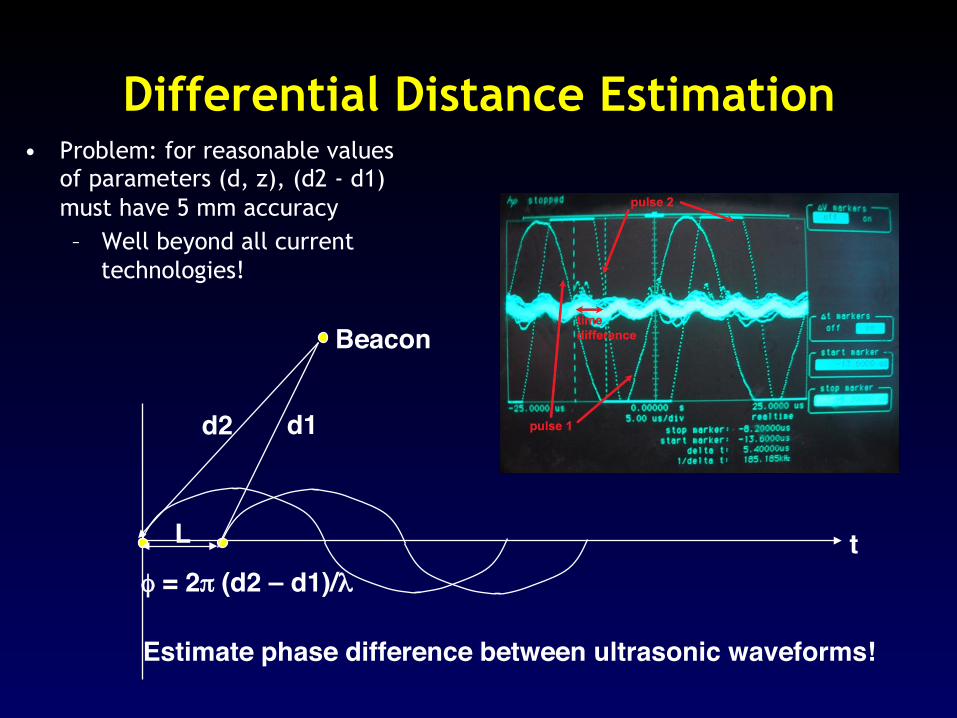
Differential Distance Estimation • Problem: for reasonable values
of parameters (d, z), (d2 - d1) must have 5 mm accuracy – Well beyond all current
technologies!
d2 d1
φ = 2π (d2 – d1)/λtL
Beacon
Estimate phase difference between ultrasonic waveforms!


