
22nd International Congress of Mechanical Engineering (COBEM 2013) November 3-7, 2013, Ribeirão Preto, SP, Brazil
Copyright © 2013 by ABCM
THE DIFFERENCE BETWEEN MERKEL AND POPPE MODELS AND ITS
INFLUENCE ON THE PREDICTION OF WET-COOLING TOWERS
Rodrigo Figueiredo Abdo PUC Minas, Belo Horizonte - MG [email protected] Yuri Hovadick Barros Rodrigues PUC Minas, Belo Horizonte - MG [email protected] Víctor Leonardo de Oliveira Silva PUC Minas, Belo Horizonte - MG [email protected] Luben Cabezas Gómez UFJS, São João Del Rei –MG - Brasil [email protected]
Sérgio de Morais Hanriot PUC Minas, Belo Horizonte - MG [email protected] Abstract. This work provides a comparative and detailed study of the proposed equations for counter flow wet cooling tower analysis. Without assuming any value to describe the physical processes in the cooling tower, Poppe developed a model that describes rigorously the heat and mass transfer process during its operation and is well suited to others types of cooling towers analysis when higher degree of accuracy is an important factor. Merkel’s equations are part of a model basically originated from subsequent simplifications in physical factors such as the Lewis relation and boundary conditions. The equations proposed by Poppe analysis method have the mains objective to give more detailed representation on Merkel´s number. The difference is analysis and solutions techniques of the proposed models of Merkel and Poppe are described with the aid of charts and diagrams that represents the changes in the enthalpy and the tower characteristic curve for a given process. The main results as Merkel´s number (NTU), moist air at water interface properties for both methods and Lewis relation are shown in a comparative form. Keywords: Heat and mass transfer, Cooling tower, Merkel and Poppe Method
1. INTRODUCTION
Cooling towers are devices widely used in industry, in processes such as power generation, refrigeration plants,
chemical and petroleum industries. They represent an important item, often essential, providing reduced environmental impacts and operating costs in the thermal systems where are used. There are several types of cooling towers: Natural, forced, crossflow, counterflow, evaporative and non evaporative. Basically, its working principle is to transfer the thermal energy (sometimes residual) of one fluid, commonly water, to the air through a heat and mass transfer process.
The great simplicity of this system, which requires relatively much less resources than others, such as compression refrigeration systems, is the key factor to its increased use. However, deviations from design specifications can result in major operational problems, not only on other dependent thermal circuits, as well as on the total cost of the installation.
There are environmental constraints laws that regulate and require the use of the cooling tower. In 1973, the Environmental Protection Agency (EPA) (Chan and Golay, 1977) emphasized the use of cooling towers, especially with the growing demand in the wise use of water.
The heat transfer process involves latent heat due to the water vapor mass which vaporizes during the process and sensible heat due to temperature differences. It is estimated that 80% is due to the latent heat and 20% to sensible heat (Perry and Green, 1997). Because of evaporative losses, drag and purging of the tower, it is essential that there is a replacement of the mass of water lost. The cooling speed and the final temperature of the water depends on various parameters, such as mass flow rates of water and air, weather conditions and the desired exit temperature. Due to so many factors that depend on and affect the environment it is essential the study of mathematical models for the design of tower components in order to obtain precise project results. The quality of the main input data is also very important.
In recent years, many studies have been developed to analyze the integration of cooling towers in the main thermal system where they are used. In this paper two basic heat and mass transfer mathematical models, denominated as Merkel and Poppe models, as presented in by Kloppers and Kröger (2005a), are used for performing numerical
ISSN 2176-5480
8843

Abdo, R.F.,Rodrigues, Y.H.B., Silva, V.L.O., Cabezas-Gómez, L., Hanriot, S.M. The Difference Between Merkel and Poppe Models and Its influence on the Prediction of Wet-Cooling Towers
simulations of counterflow cooling towers. The first model combines the coefficients of sensible heat and mass transfer and a global coefficient able to predict with some accuracy the outlet temperature of the cold water. In this model, considerations are made to simplify it, for example, assume that the Lewis factor is equal to 1 and that the reduction in water flow rate is negligible in the overall energy balance. Besides this simplification it still considers that the air must be saturated by water vapor at the tower output. In some way, these simplifications make unfeasible the knowledge of the air temperature during the evaporation process, being thus estimated by mathematical functions. The Merkel model is compose of the so-called Merkel equation and by the differential equation of energy conservation.
The Poppe Model does not considers the simplifications adopted in the Merkel Model, resulting in a system of three differential equations plus a relation for the Lewis number, that allow to compute the thermodynamic conditions of the air and water at the tower exit, and further determine the temperature variations of the two fluids in the tower. Comparing the two mathematical models is noted at a first glance the necessity of using one or more numerical methods for solving them. In the case of the Merkel Model this is mainly due to the difficulty in predicting the physical properties accurately along the tower. In the case of Pope Model is necessary to know the thermodynamic properties in each control volume.
Qualitatively, the model proposed by Merkel is simple in terms of the mathematical formulation and can promote a time saving desirable to estimate the main characteristics of a cooling tower (Asvapoositkul and Treeutok, 2012). It also allows to solve with security a relatively large part of the usual problems. On the other hand, the model proposed by Poppe is costly, both to the conditions of crossflow or counterflow as it can be solved at least by the four order Runge-Kutta method.
In a study by Fernandes (2012) the value of the number of Merkel evaluated by the method of Poppe is approximately 9% higher than that obtained by the method of Merkel. However, by Poppe it is possible to calculate not only the quantity of water in the air stream at each point in the tower, but several other factors such as air temperature, humidity and evaporation losses and tower drag. The choice of one model or another depends on several aspects, namely economic, time and even technological resources. Importantly, the cooling tower has major limitations to natural climatic conditions, making it impossible to get a cooling process with inadequate environmental conditions.
Although the towers can be classified in different ways, the basic way to differentiate them is in relation to the process of heat transfer: Evaporative cooling, non evaporative cooling, or both processes operating simultaneously (U.S. Environmental Protection Agency, 1995). Sub classifications include the type of drawing, air flow, fan position and the distribution of water.
Considering the type of air circulation, there are three major groups that classify the towers: the atmospheric circulation, natural and mechanical, the last of which is divided into forced and induced flow. For the study and implementation of mathematical models proposed by Merkel and Poppe were adopted evaporative cooling towers with mechanical air forced circulation in a counter current with the water flow.
In this particular type of tower, widely used in the industries, the hot water is projected through sprinklers on top of the equipment for the purpose of spraying and thus increase its contact area with the air. Allied to this, this mixture undergoes a filling package whose main function is to further increase the contact surface are with the air drawn by a fan also located at the top of the equipment.
The aim of this paper is to develop a comparative study of the predictive ability of the Merkel and Pope models. Therefore both mathematical models were programmed and solved in EES (Engineering Equation Solver). In the work are compared the output properties of water as the enthalpy, temperature, humidity, and evaporation losses. 2. LITERATURE REVIEW
A counterflow cooling tower is shown schematically in Fig (1) (Lemouari and Boumaza, 2010). It consist on several
parts such as mist eliminator, fan, filling, housing, nozzles, shutters and a containment basin. The water to be cooled is pumped through a pipe located at the top of the tower, which is then distributed through nozzles for filling. Simultaneously, the air enters the lower region of the tower by shutters induced by an axial fan located at the top. The meeting of these two fluids occurs in the filling, whose function is to allow a heat exchange between the hot water and the air as efficiently as possible.
ISSN 2176-5480
8844

22nd International Congress of Mechanical Engineering (COBEM 2013) November 3-7, 2013, Ribeirão Preto, SP, Brazil
Figure 1. Schematic of a counterflow cooling tower (Lemouari and Boumaza, 2010)
According to Mohiuddin and Kant (1996a), Walker et al. where the first to propose the basic theory on the
operation of a cooling tower, deriving initially the basic equations for the mass and energy conservation for each process separately. Merkel used these two equations at the same time, combining the coefficients of sensible heat transfer and mass transfer, in a single global coefficient based on enthalpy difference as the driving force that allows the overall heat and mass transfer process.
The Poppe Model was developed in the 70s, without assuming any simplifying assumption adopted by Merkel, providing model results in a good agreement with field measurements.
2.1 Merkel Model
After its publication, the model proposed by Merkel was neglected until 1941 when his article was translated into
English (Kloppers, 2003). Since then, it has been widely applied and recommended by international standards (Britsh Standard, 1988), even with a level of accuracy lower than expected.
The simplifications that lead the final equations of Merkel Model are: Lewis factor equal to 1, the air at the exit of the tower is saturated and the reduction in the flow of water due to evaporation is neglected in the energy balance.
Applying the mass and energy balances based on Fig (2), where the air is in the opposite direction to the flow of water it is possible to get two equations, as described by Kloppers and Kröger (2005a):
Figure 2. Contact of air and water in a counterflow cooling tower (Kloppers and Kröger, 2005a)
mamaswa
frfidma iim
Aahdz
di (1)
ISSN 2176-5480
8845
Abdo, R.F.,Rodrigues, Y.H.B., Silva, V.L.O., Cabezas-Gómez, L., Hanriot, S.M. The Difference Between Merkel and Poppe Models and Its influence on the Prediction of Wet-Cooling Towers
dzdi
cmm
dzdT ma
pww
aw 1 (2)
Where: = Specific enthalpy of moist air (J/kg) = Specific enthalpy of saturated air at the interface at the water temperature J/kg) = Mass flow rate of air (kg/s) = Mass flow rate of water (kg/s) = Mass transfer coefficient (kg/m²s) = Surface area occupied by the falling water or area of the filler per unit volume of the tower (m2 m-3) = Cross-sectional area of the tower (m²) = Specific heat of water (J/kg K) = Elevation of the tower (m) = Water temperature (K)
Equation (1) represents the variation of the air-water vapor mixture, obtained from the mass and energy
conservation equations for the mixture. The Eq. (2) represents the water temperature variation obtained from the energy balance in a differential element dz.
In Eq. (1) it is possible to realize that the potential for heat and mass transfer is given by the difference in specific enthalpy of the air at the air-water interface and the specific enthalpy of the air. Substituting Eq. (2) into Eq. (1) and integrating, we have:
wi
w
T
T mamase
wpw
w
fifid
w
fifrfidm ii
dTcG
Lahm
LAahMe
0
(3)
Where: = Merkel number according to the Merkel Model = Height of filling, or active Volume per unit area (m) = Water flux (kg/m2 s) = Integration factor
The number of Merkel is a dimensionless coefficient of performance. Equation (3) can be solved if the inlet and
outlet temperatures of the water, the water and air mass flow rates and the air inlet conditions in the cooling tower are known, since mass transfer coefficients and the area per unit volume quantities are extremely difficult to determine.
In the literature (Kloppers and Kröger, 2005a), the commonly notation KaV/L is adopted where ; ; e .
It can be seen that the Merkel number can be achieved by simple solution of the integral of Equation (3), however, it is necessary to predict the enthalpy of the air according to the temperature variation of the water along the tower. For this, using an energy balance with the global average specific heat of water ( is obtained:
maawpwmw dimdTcm (4) Since the air flow rate can be determined from the mass and energy balance assuming no water replacement:
wviiwvooaiao
wowiwia iwiwii
iimm (5)
Where: = Mass flow rate of water into the inlet (kg/s) = Specific enthalpy of the water at inlet (J/kg K) = Specific enthalpy of the water at the outlet (J/kg K) = Specific enthalpy of the air at inlet (J/kg K) = Specific enthalpy of the air at outlet (J/kg K) = Specific enthalpy of steam at inlet (J/kg K) = Specific enthalpy of steam at outlet (J/kg K) = Absolute humidity of the air at income (kgw/kga)
ISSN 2176-5480
8846

22nd International Congress of Mechanical Engineering (COBEM 2013) November 3-7, 2013, Ribeirão Preto, SP, Brazil
= Absolute humidity of the air at outlet (kgw/kga) Thorough Eqs. (4) and (5) it can be noted again the consequences of the simplifications adopted by Merkel. The fact of water mass loss along the tower being ignored, make some variables in the mass and energy constants rather than functions that depend on other variables. 2.2 Poppe Model
Without assuming the simplification adopted by Merkel, the mass and energy balances originated in Fig (2) for the saturated and unsaturated air give rise, after algebraic manipulation, to three differential equations, according Kloppers and Kröger (2005a):
wpwswwvswmamaswfmamasw
swa
wpw
w TcwwiwwiiLeii
wwmmc
dTdw
1
(6)
wpwswwvswmamaswfmamasw
swwpw
a
pww
w
ma
TcwwiwwiiLeiiwwTc
mcm
dTdi
11 (7)
wpwswwvswmamaswfmamasw
pw
w
P
TcwwiwwiiLeiic
dTdMe
1 (8)
Where: = Number of Merkel according to the Poppe Model = Absolute humidity (kgw/kga) = Absolute humidity of saturated air (kgw/kga) = Specific enthalpy of steam (J/kg K) = Lewis factor
The Lewis factor can be calculated according to Bosnjakovic (1965):
622.0622.0ln
1622.0622.0865.0 667.0
ww
ww
Lesw
sw
f (9)
The ratio between the mass flow rate of air and water changes as the air moves toward the exit of the tower. This change may be calculated according to the control volume adopted in Figure (3):
Figure 3. Control volume in the filling (Kloppers and Kröger, 2005a)
It is expressed as follows:
ISSN 2176-5480
8847

Abdo, R.F.,Rodrigues, Y.H.B., Silva, V.L.O., Cabezas-Gómez, L., Hanriot, S.M. The Difference Between Merkel and Poppe Models and Its influence on the Prediction of Wet-Cooling Towers
wwmmm oawwi (10)
Rearranging the Equation (10):
ww
mm
mm
mm
owi
a
a
wi
a
w 1 (11)
Kloppers and Kröger (2005a) suggest that the value of absolute humidity output is estimated by some interactions before solving the system of differential equations. According to Mohiuddin and Kant (1996b), assuming no purge losses occur, every 5.56 ° C variation in temperature of water, produce 1.0% of the total circulating water evaporation. They also assume that 0.1 to 0.3% of the circulating water is lost by drag, then:
iai
wiwowiwi
o wm
mTTm
w
001.001.056.5 (12)
Where: = Water inlet temperature (K) = Water outlet temperature (K)
3. MODELING
For analysis of both models in relation to the Merkel number were adopted three different methods of numerical
integration, two different for the Merkel model, and one for the Poppe model. For the Merkel method, which uses the Eq. (3), was applied the integration technique of Tchebyshev as described
by Lucas et al. (2013), consisting on the following equation:
4
1
14 j j
wowipwm
T
T mamase
wpwm i
TTcii
dTcL
KaV wi
wo
(13)
Where describes the difference in specific enthalpy of saturated air at the interface at water temperature and
specific enthalpy of humid air as a function of the real roots of the polynomial of Tchebyshev of fourth order. Table (1) summarizes the procedure for the resolution:
Table 1. Procedures for resolution for the number of Merkel by Tchebyshev.
Water Temperature (ºC)
- - -
- - -
- - -
- - -
(-) Values to be calculated
The second method of integration to compute the number of Merkel is to solve the integral represented by Eq. (3) with the aid of EES (Engineering Equation Solver), specifying the value of according to Eq. (4):
wi
wo
T
Tmaiwow
ai
pwmwimasw
wpwm
iTTmcm
i
dTc (14)
For the model proposed by Poppe, the numerical method used is the Runge-Kutta method of four order. Therefore,
the equation (6), (7) and (8) can be rewritten as follows, according to Kloppers and Kröger (2005a):
ISSN 2176-5480
8848

22nd International Congress of Mechanical Engineering (COBEM 2013) November 3-7, 2013, Ribeirão Preto, SP, Brazil
wmaw
TiwfdTdw ,, (15)
wmaw
ma TiwgdTdi ,, (16)
wmaw
P TiwhdT
dMe ,, (17)
And solved as it follows:
622 4,13,12,11,1
1
nnnnnn
jjjjww (18)
622 4,13,12,11,1
1
nnnnnmanma
kkkkii (19)
622 4,13,12,11,1
1
nnnnnPnP
llllMeMe (20)
The parameters for analysis are calculated as it follows:
niTTT wowi
w
(21)
nnmanwwn wiTfTj ,,.1,1 (22)
nnmanwwn wiTgTk ,,.1,1 (23)
nnmanwwn wiThTl ,,.1,1 (24)
2,
2,
2. 1,11,1
2,1n
nn
nmaw
nwwn
jw
kiTTfTj (25)
2,
2,
2. 1,11,1
2,1n
nn
nmaw
nwwn
jw
kiTTgTk (26)
2,
2,
2. 1,11,1
2,1n
nn
nmaw
nwwn
jw
kiTThTl (27)
2,
2,
2. 2,12,1
3,1n
nn
nmaw
nwwn
jw
kiTTfTj (28)
2,
2,
2. 2,12,1
3,1n
nn
nmaw
nwwn
jw
kiTTgTk (29)
ISSN 2176-5480
8849

Abdo, R.F.,Rodrigues, Y.H.B., Silva, V.L.O., Cabezas-Gómez, L., Hanriot, S.M. The Difference Between Merkel and Poppe Models and Its influence on the Prediction of Wet-Cooling Towers
2,
2,
2. 2,12,1
3,1n
nn
nmaw
nwwn
jw
kiTThTl (30)
2,13,14,1 ,,. nnnnmawnwwn jwkiTTfTj (31)
2,13,14,1 ,,. nnnnmawnwwn jwkiTTgTk (32)
2,13,14,1 ,,. nnnnmawnwwn jwkiTThTl (33)
Kloppers and Kröger (2005a) reported that for the characterization of the number of differential intervals in the cooling tower, ni, it is required a minimum of 5 sub-divisions of the tower to obtain an appropriate result. In this work were adopted 20 intervals. Three separate cases of operating a cooling tower were studied, as shown in Table (2):
Table 2. Studied Cases. Properties Case 1 Case 2 Case 3 (ºC) 40 40 40 (ºC) 30 30 30 (ºC) 35 17 7
(kg/s) 4 4 4 (kg/s) 4.908 5.259 11.25
w (kgw/kga) 0.003474 0.001192 0.0006157 Absolute pressure (kPa) 101.325 101.325 101.325
4. RESULTS
Based on the proposed models and their resolutions for the three cases proposed in Table (2), in Tables (3) and (4) are shown a summary of the results for the main system properties and the Merkel number for each type of integration proposed. As can be seen some variables present slightly higher errors, which may create differences between what might happen in practice and what was predicted in the design phase.
Table 3. Thermodynamic properties of the system.
Properties Case 1 Case 2 Case 3 Merkel Poppe Merkel Poppe Merkel Poppe
(ºC) 35 35 17 17 7 7 (ºC) 25.47 33.11 18.35 21.1 7.39 10.07
(kg/s) 4 4 4 4 4 4 (kg/s) 4 3.93 4 3.94 4 3.94
(kgw/kga) 0.0035 0.0035 0.0012 0.0012 0.0006 0.0006 (kgw/kga) 0.0207 0.0183 0.0132 0.0126 0.0064 0.0056
Table 4. Merkel number.
Case Merkel Poppe Tchebyshev Integral Runge-Kutta
1 0.6157 0.6154 0.7114 2 0.4484 0.4483 0.5091 3 0.372 0.372 0.4181
It can be verified that the variations of the main system properties differ along the tower, which is a clear
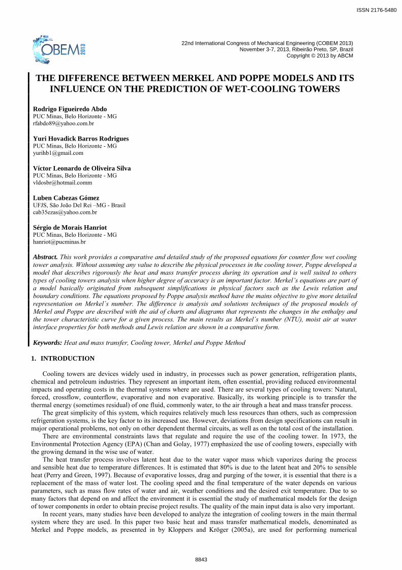
consequence of the simplifications assumed by Merkel to formulate it model. The factors that could cause major problems in an industrial plant would be the outlet temperature of the air with his absolute humidity. Some processes rely on a prediction closer to reality as possible. To further illustrate how the other characteristics diverge along the tower, follow the charts. From Figure (4) it cannot be noticed a great variation of the specific enthalpy between both models. The largest variation becomes present as the inlet temperature of the air increases.
ISSN 2176-5480
8850
22nd International Congress of Mechanical Engineering (COBEM 2013) November 3-7, 2013, Ribeirão Preto, SP, Brazil
Figure 4. Specific enthalpy x Water temperature
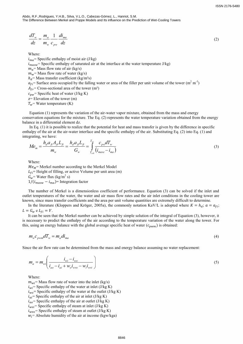
The fact that the Merkel Model considers saturated air output implies in a higher absolute humidity of the outlet air,
which is not always the case. Coupled with this, the higher the air temperature, the greater is the possible variation for the cooling process occurs by adding water to the air. As one of the main factors that support the variations shown in Fig (4), in Fig (5) is shown the dissipation of water vapor in the air mass present in the tower. It can be seen that for the same boundary conditions, the Poppe Model predicts moisture levels lower than that proposed by Merkel. No information about the humidity, besides the inlet and outlet conditions are provided in the Merkel Model, appearing therefore as a straight line.
Figure 5. Absolute humidity x Water temperature
The difference between the specific enthalpy of the air at the air-water interface and the specific enthalpy of the air
is the main physical mechanism that causes the cooling tower work. The curves were obtained from the Eqs. (4) and (7), see Figure (6). The biggest difference between these two variables are due to the fact that the Eq. (4) neglects the changes in airflow due to evaporative losses and drag. One of the main reasons that explains the Merkel Number being superior by the Poppe Model.
As can be seen in Figure (7) the evaporation rate is higher with increasing inlet temperature of the air. According to Kloppers and Kröger (2005b), Grange in their comparative study demonstrates that the Merkel model tends to underestimate the amount of water that evaporates when compared to Poppe model.
The smaller the Lewis factor is, the higher the evaporation rate, however, the Merkel model assumes that beyond the Lewis factor is equal to one, the air is saturated at the output. Poppe uses the Lewis factor according to equation (9), and together with equation (6) allow to balance the losses.
ISSN 2176-5480
8851

Abdo, R.F.,Rodrigues, Y.H.B., Silva, V.L.O., Cabezas-Gómez, L., Hanriot, S.M. The Difference Between Merkel and Poppe Models and Its influence on the Prediction of Wet-Cooling Towers
Figure 6. Integration factor x Water temperature
Figure 7. Accumulated losses by evaporation and drift x Water temperature
The curves of Figure (8) are a consequence of the graphics displayed in Figs. (4) and (5). The greater the amount of
water in the air, the lower dry bulb temperature and thus lower its enthalpy. This feature can be best seen in Figure (9). The temperature profiles of air and water showed distinct endpoints, as the inlet temperature of the air increases.
Figure 8. Air temperature x Water temperature
It is noticed that in cases of high inlet temperature of air and water, as in case 1, the difference between the curves
is greater due to the greater possibility of cooling when it moves towards the wet bulb temperature.
ISSN 2176-5480
8852

22nd International Congress of Mechanical Engineering (COBEM 2013) November 3-7, 2013, Ribeirão Preto, SP, Brazil
Figure 9. Psychometric chart
The psychometric chart shown in Figure (9) is the reflection of all previous charts. The outlet temperature of the air according to the analysis by Poppe and Merkel are not as close to each other. The air temperature calculated by both methods occupy a region of approximately the same enthalpy. This difference tends to decrease as the temperature of the air becomes more mild.
In terms of the energy balance, both models perform relatively well, but analyzing the output characteristics, and especially if some process would depend on a prevision of these properties, the Pope model should be used, because as shown in the chart, the output properties calculated by Merkel occupy only the row whose relative humidity is 100%. It is noted that when the inlet air temperature is high, case 1, a greater range of possibilities for the output may be expected due to large graphical area before the air enters in a supersaturation regime. 5. CONCLUSIONS
From the present study it can be say that the choice between one model and another is very subjective and should be
examined carefully. If dealing with a basic design, in that it takes only an estimate for a pre-sizing, the Merkel model is more appropriate because it does not require a more accurate numerical integration technique and can be done relatively quickly once the boundary conditions are already known.
As the level of detail and accuracy increases, the internal operational conditions inside the cooling tower are required to be known, the Poppe Model gains space and must be implemented in order to prevent that the equipment works below or above the required operating conditions.
Impacts in a correct sizing of a cooling tower may be relevant major in a long term. The power economy should be not only due to the accuracy in selecting a tower, but also by power consumption of the fan and the other variables that use the Merkel number for its computation, as the filler.
6. ACKNOWLEDGEMENTS
The authors wish to thank CNPq and FAPEMIG for the financial support to this work.
7. REFERENCES
Asvapoositkul, W. and Treeutok, S.,2012. “A simplified method on thermal performance capacity evaluation
of counter flow cooling tower”. Department of Mechanical Engineering, King Mongkut’s University of Technology Thonburi.
Chan, Joseph Kwok-Kwong, 1977. Comparative evaluation of cooling tower drift eliminator performance. Ph.D. thesis, Massachusetts Institute of Technology, Cambridge.
Green, D.W. and Perry, R.H., 1997. Perry's Chemical Engineers' Handbook. McGraw-Hill, 7th edition. British Standard 4485, 1988. Water cooling towers, Part 2: methods for performance testing. Bosnjakovic, F., 1965. Technische Thermodinamik. Theodor Steinkopf, 3th edition. Fernandes, M., 2012. Proposta e comparação de um modelo fenomenológico com base em alto transporte de massa e
supersaturação para torre de resfriamento de água. MD.D. thesis, Universidade de São Paulo, São Paulo.
ISSN 2176-5480
8853

Abdo, R.F.,Rodrigues, Y.H.B., Silva, V.L.O., Cabezas-Gómez, L., Hanriot, S.M. The Difference Between Merkel and Poppe Models and Its influence on the Prediction of Wet-Cooling Towers
Kloppers, J.C., 2003. A critical evaluation and refinement of the performance prediction of wet-cooling towers. Ph.D. thesis, University of Stellenbosch, Stellenbosch.
Kloppers, J.C. and Kröger, D.G., 2005a. “A critical investigation into the heat and mass transfer analysis of counterflow wet-cooling towers”. International Journal of Heat and Mass Transfer, Vol. 48, p. 765-777.
Kloppers, J.C. and Kröger, D.G., 2005b. “The Lewis factor and its influence on the performance prediction of wet-cooling towers”. International Journal of Thermal Sciences, Vol. 44, p. 879-884.
Lemouari, M. and Boumaza, M., 2010. “Experimental investigation of the performance characteristics of a counterflow wet cooling tower”. International Journal of Thermal Sciences, Vol. 49, p. 2049-2056.
Lucas, M., Ruiz, J., Martínez, P.J., Kaiser, A.S., Viedma, A and Zamora, B., 2013. “Experimental study on the performance of a mechanical cooling tower fitted with different types of water distribution systems and drift eliminators”. Applied Thermal Engineering, Vol. 50, p. 282-292.
Mohiuddin, A.K.M. and Kant, K., 1996a. “Knowledge base for the systematic design of wet cooling towers. Part I: Selection and tower characteristics”. Int. J. Refrigeration, Vol. 19, p. 43-51.
Mohiuddin, A.K.M. and Kant, K., 1996b. “Knowledge base for the systematic design of wet cooling towers. Part II: Fill and other design parameters”. Int. J. Refrigeration, Vol. 19, p. 52-60.
U.S. Environmental Protection Agency, January 1995. Compilation of Air Pollutant Emissions Factors Volume 1: Stationary Point and Area Sources. No. AP-42 Section 13.4, 5th edition.
8. RESPONSIBILITY NOTICE
The author(s) is (are) the only responsible for the printed material included in this paper.
ISSN 2176-5480
8854


