
University of Calgary
PRISM: University of Calgary's Digital Repository
Graduate Studies Legacy Theses
1998
Theoretical and experimental study of coupled
torsional - lateral vibrations in rotor dynamics
Perera, Ittapana
Perera, I. (1998). Theoretical and experimental study of coupled torsional - lateral vibrations in
rotor dynamics (Unpublished master's thesis). University of Calgary, Calgary, AB.
doi:10.11575/PRISM/19779
http://hdl.handle.net/1880/26192
master thesis
University of Calgary graduate students retain copyright ownership and moral rights for their
thesis. You may use this material in any way that is permitted by the Copyright Act or through
licensing that has been assigned to the document. For uses that are not allowable under
copyright legislation or licensing, you are required to seek permission.
Downloaded from PRISM: https://prism.ucalgary.ca

THE UNIVERSITY OF CALGARY
Theoretical and Experimental Study of Coupled Torsional - Lateral
Vibrations in Rotor Dynamics
by
Ittapana Perera
A THESIS
SUBMITTED TO THE FACULTY OF GRADUATE STUDIES
IN PARTIAL FULFILLMENT OF THE REQUIREMENTS FOR THE
DEGREE OF MASTER OF ENGINEERING
DEPARTMENT OF MECHANICAL ENGINEERING
CALGARY, ALBERTA
DECEMBER, 1998
43 Ittapana Perera 1998

National Library Bibliotheque nationale du Canada
Acquisitions and Acquisitions et Bibliographic Services services bibliographiques
395 Wellington Street 395, rue Wellington Ottawa ON K I A ON4 Ottawa ON K I A ON4 Canada Canada
The author has granted a non- exclusive licence allowing the National Library of Canada to reproduce, loan, distribute or sell copies of this thesis in microform, paper or electronic formats.
The author retains ownership of the copyright in this thesis. Neither the thesis nor substantial extracts &om it may be printed or othefwise reproduced without the author's permission.
L'auteur a accord6 une licence non exclusive pennettant a la Bibliotheque nationale du Canada de reproduire, prgter, distribuer ou vendre des copies de cette these sous la fome de microfiche/film, de reproduction sur papier ou sur format Bectronique.
L'auteur conserve la propriete du droit d'auteur qui protege cette these. Ni la these ni des extraits substantiels de celle-ci ne doivent etre imprimes ou autrement reproduits sans son autorisation.

Abstract
The coupled torsional-lateral vibrations in single and two-disk rotor systems are studied
analytically and experimentally over the operational frequency range. A comparison of
analytical and experimental results is done for a motor pump assembly. The results
presented shows the existence and significance of the coupling phenomenon in rotating
machinery.
iii

Acknowledgements
My sincere thanks to Dr. 0. Vinogradov not only for his guidance, patience and
trust put on this work, but also for the friendly help given through out my study at the
University of Calgary.
A special thanks to my loving wife Dharshi for her understanding, help and
constant support.
I would like to thank my employer Kadon Electro Mechanical Services of
Calgary, and my colleagues Mike Greer, Ray Gibbs, Dr. Don Bayly and Dr. Tony Taylor
for their support and encouragement to complete this project.
My special thanks to Victor Obeid and Chuck Yeiser at Rotor Bearing
Technology and Software Inc. in Pennsylvania, USA for providing me the algorithm
from "Numerical Recipies" to solve the nonlinear differential equations and compute the
results.

To Maitlzri and Slzeharz

Table of Contents
. . ........................................................................................... Approval.. 11
... ........................................................................................... Abstract. . I I I
............................................................................. Acknowledgements.. .iv
........................................................................................ Dedication.. ..v
............................................................................... Table of contents.. ,.vi
....................................................................................... List of Tables i x
.................................................................................... List of Figures.. .x
......................................................................................... List of Plots xi
Chapter 1
............................................................................ Introduction.. .1
.................................................... 1.1 Need for the study.. 6
............................................................ 1.2 Objectives.. .7
Chapter 2
.............................. State of the art and review of background material.. .12
Chapter 3
..................................... Analysis Model 1 - Single Disk Rotor System. 24
................................................. 3.1 Lagrange's Equation. 25

. 3.2 Model I Single Disk Rotor System ............................... 26
3.3 Lateral response ....................................................... 32
............................................................. 3.4 Conclusion 35
Chapter 4
Analysis Model I1 w Two Disk Rotor System ....................................... 36
.............................................. Two Disk Rotor Model 37
................................................... Method of Solution 47
......................... Two disk Rotor Mode1 Dimensional Data 48
Part 1 - Analysis of Response Frequencies of
.................... Coupled Torsional-Lateral Vibrations 49
......................................... Input Test Data and Results 50
Part I1 - Response Analysis of the Coupled
Torsional-Lateral Vibrations at Natural
................................... Frequencies of the Rotor 54
.......................................................... Conclusions -57
Chapter 5
...................................................... Analysis of Experimental Data 60
Chapter 6
................................................ Conclusions and Recommendations 73
.................................................................................... Bibliography 77
................................................................................... Appendix - A 80
................................................................................. Appendix - B 1 92
vii

................................................................................ Appendix . B2 108
................................................................................ Appendix . C 1 120
................................................................................ Appendix . C2 123
................................................................................ Appendix = D2 125
viii

List of Tables
................................................................................... Table 4.1 53
Table 4.2 ................................................................................... 55
.................................................................................. Table 4.3 .57

List of Figures
Figure 1.1 : Imbalance rotating disk .................................................... 2
Figure 1.2 : Forces on an imbalance disk .............................................. 3
Figure 3.1 : Eccentric disk mounted on a mass-less shaft ............................ 26
Figure 3.2 : Single disk rotor supported on a rigid bearing .......................... 27
Figure 3.3 : Single disk rotor coordinate system ...................................... 27
Figure 3.4 : Disk center motion .......................................................... 33
Figure 3.5 : Polar and Cartesian coordinates .......................................... 34
Figure 4.1 : Two eccentric disks mounted on a mass-less shaft .................... 37
Figure 4.2 : Axis of rotation of two disk rotor system ............................... 38
........................ Figure 4.3 : Cartesian coordinates of two-disk rotor system 38
Figure 4.4 : Generalized coordinates and dimensions of two disk rotor system.39

List of Plots
................................................ Plot 4.1 : Frequency response function 56
................................................ Plot 4.2 : Frequency response function 59
............................ Plot 5.1 : Detail waveform plot of torsional oscillations 65
....................................... Plot 5.2 : Cascade plot of torsional oscillations 66
........................................... Plot 5.3 : Cascade plot of lateral vibrations 67
.................................. Plot 5.4 : Detail waveform plot of lateral vibration 68
......................................... Plot 5.5 : Dimensional details of pump rotor 69
.......................................... Plot 5.6 : First bending mode of pump rotor 70
...................................... Plot 5.7 : Second bending mode of pump rotor 71
......................................... Plot 5.8 : Third flexing mode of pump rotor 72
.................................. . Plots A1 -A 10 : Time Waveforms and Spectra 83 91
.......................... Plots B 1.1 -B 1.13 : Time Waveforms and Spectra .9 5. 108
.............................. Plots B2 . LB2.9 : Time Waveforms and Spectra 1 1 1- 1 19

Page I
CHAPTER 1
INTRODUCTION
The phenomenon of coupling between torsional and lateral vibrations in rotor disk
assemblies is described in this chapter. The factors that cause the coupling between the
two vibration modes, and the reason for their presence for all configurations of the
systems are explained. The differences between the couplings in linear and nonlinear
systems are also discussed in the chapter.
Figure 1.1 shows a configuration of a single disk rotor system. A mass-less shaft with a
disk at the center is supported on two rigid bearings. The center of the mass of the disk e
'm' is offset by eccentricity 'e'.

Page 2
Figure 1.1: Imbalance rotating disk
When the rotor is rotated at a speed of# the mass at eccentricity 'e' will produce a
.I
centrifugal imbalance force on the shaft of magnitude m e o '. This rotating imbalance *
force will cause the shaft to bend and whirl around the axis of bearing centers. If the
vibrations of the shaft are measured in terms of the lateral displacement coordinates X
and Y, we will see that the shaft is responding harmonically in the X and Y directions,
and the oscillations occur at the frequency of the rotational speed of the shaft.
If an external oscillatory torque is applied to the rotor, while the shaft is rotating, a
torsional oscillation will be superimposed on the rotation of the system. These torsional
oscillations will be in addition to the lateral vibration of the system, due to imbalance of
the rotor. The torsional oscillations will occur at the same frequency as the oscillatory

Page 3
torque w , while the lateral vibration occurs at the rotating speed of the shaft assembly at t
W .
Figure 1.2: Forces on an imbalance disk
Figure 1.2 shows a diagram of forces acting on the shaft and on the center of gravity of
the disk. The center of the shaft is at point 'S' and '0' is the equilibrium point where the
center of the shaft lies when the rotor is not rotating. The center of gravity of the disk is
at point 'G'. The spring forces kx and h~v are generated due to the bending of the shaft,
and me and my are the inertia forces due to the lateral motion of the eccentric mass.
The angular moment of inertia of the center of gravity of the disk is I @ .
The torsional oscilIations of the disk will cause the eccentric mass to oscillate with
angular motion, around the center axis of the shaft. This results in torsional inertia forces
on the disk, which will couple with the laterai dynamic forces acting on the shaft. This
produces the coupled torsional/lateral vibration of the system. When the forces are
coupled the motions associated with the forces, namely torsional and lateral motions, also
become coupled, i.e. they interact with each other.
Page 4
The overall set of equations describing the system becomes coupled and nonlinear.
Because of the coupling, the torsional vibration interacts with the lateral vibration of the
system. In the above example, when an oscillatory torque is applied to the rotor, a
torsional vibration occurs, and induces a lateral vibration on the rotor assembly. This
vibration is in addition to the laterd vibration due to imbalance of the eccentric mass.
The frequency of the torsionally induced vibrations will be different from that caused by
the imbalance excited vibrations of the system. In a simple way we could state that the
lateral vibrations are affected by the torsional oscillations occurring in the system.
As it is known in linear vibrations a set of coupled equations of motion can be uncoupled
by a set of principal coordinates, and there is at least one set of principal coordinates for
every linear system. The principal coordinates are found by using the orthogonality
properties of linear systems. The system characteristics and properties are not affected by
using the principal coordinates to define the system. Thus in a linear system the
existence of a coupling merely depends on the selection of coordinates to define the
system and the coupling is not an inherent property of the system.
In contrast to linear systems, the orthogonality propenies do not apply to nonlinear
systems. In a nonlinear system, a set of principal coordinates cannot be found to
decouple the equations of motion. Thus in a coupled nonlinear system, for all sets of ,
generalized coordinates, the equations of motion will always remain coupled.

Page 5
Summarizing the above facts we could state the following.
In rotor assemblies where mass imbalances are present, the torsional and lateral
vibrations are coupled and the systems are nonlinear. The torsional vibrations interact
with the lateral vibrations in the system. When torsional vibrations are present they
induce lateral vibrations in the system. Similarly the lateral vibrations induce torsional
vibrations in the system. In other words, we could state that lateral vibration will occur in
response to a torsional vibration in the system, and a torsional vibration will occur in
response to a lateral vibration in the system. No matter how the coordinates are selected
to define the configuration of a system the coupling between lateral and torsional
vibrations will remain in the system.
As it is seen from the above example both the coupling and the nonlinear properties of
the system are induced by the eccentricity 'e' of the unbalanced mass, which is a physical
property of the system. In an ideal case, if there is no imbalance, where eccentricity
'e=O', the factors that cause the coupling and the non-linearity in the system are
eliminated. In this case the equations of motion for torsional and lateral vibrations can be
solved independently.

Page 6
1.1 NEED FOR THE STUDY AND ITS RELEVENCE TO THE INDUSTRY
Concerns over coupled torsionaYlateral vibrations are not new. Their existence, and
their frequency response characteristics have often been a concern of vibration analysts
and engineers. Typical questions that required answering were:
i. At what frequencies do the coupled torsional-lateral vibrations occur?
ii. How significant is their response?
iii. What are the properties that influence this coupling?
The needs for this project and its application to industry problems are presented in this
section. The objectives of the study are outlined in section 1.2.
1.2.1 Because of the fact that some degree of imbalance exists in every rotor, we could
state that torsional and lateral vibrations in all rotors are coupled. Thus in rotor
dynamics it is important to consider that the lateral and torsional vibrations are
interacting with each other.
During engineering design studies, when carrying out response analysis of rotors,
or when performing vibration analysis in machines, it was and is often considered
that the coupling between torsional and lateral vibrations are weakly non-linear,
and thus they have no significant effict on the response characteristics of the
system. Because of these assumptions their existence was ignored, and the
response analyses of torsional and lateral vibrations were performed
independently. It was considered that the torsional vibrations are due to torsional

Page 7
oscillatory forces only and the lateral vibrations are due to lateral oscillatory
forces only. Interaction between the two vibration modes, or one vibration
inducing an oscillation in the other coupled mode was never considered a
possibility. Nevertheless, when unexplainable peaks occurred, in torsional or
lateral vibration spectra, the possibility of torsional vibrations translating in to
lateral modes or lateral vibrations translating into torsional modes are often
suspected.
In the past, vibration analysts and application engineers did not have sufficient
knowledge and information with regard to the response frequencies and the
characteristics of coupled torsional-lateral vibrations in rotor sys terns. Hence,
when unknown peaks appeared in the frequency spectra, they considered the idea
of coupled torsional-lateral vibrations causing the peaks. However, lack of in-
depth knowledge and understanding of coupled torsional-lateral vibration left
many questions unanswered.
Questions which have been raised in the past with regard to their existence are:
I. Can torsional vibrations transform into lateral modes and what will
be their frequency response characteristics?
. . 11. Similarly, can the lateral vibrations transform into torsional modes
and what will be their frequency response characteristics?
ii. Can the coupled torsional-lateral vibrations excite the systems at
their natural frequencies?

Page 8
iv. Can torsional vibration be detected from measurements that are
made in lateral directions?
It is envisaged that a study of coupled torsional vibrations will answer these
questions and assist the vibration analysts and application engineers in gaining an
in-depth knowledge of the subject. It will also aid in developing design
considerations to avoid occurrence of the coupled torsional - lateral vibrations in
rotor assemblies.
1.2.2 As explained in the Introduction of this Chapter a md also proved in Chapter 7, the
coupling between the torsional and lateral vibrations in rotor assemblies are due to
the eccentricity 'e' of the imbalance mass, which is a physical property of the
system. Thus when designing rotors it is always possible to specify tolerances to
minimize the imbalance and avoid occurrence of this coupling. This project will
stress on the hportance of specifying these tolerances, particular in rotors where
both torsional and lateral vibrations are expected.
1.2.3 One of the main objectives of this study is to find the magnitudes of the coupled
torsional - lateral vibrations in rotor systems and to investigate their frequency
dependence. The purpose is also to investigate their significance.
There are many commercially available programs that perform rotor dynamic
analyses. In all of these programs the response analyses of lateral and torsional

Page 9
vibrations are performed independently. The coupled equations of motions are
not included in their analyses. The main reason for this is that non-linearity
induced due to the coupling makes the solving of equations difficult, in particular
with large rotors consisting of many elements. Often equation solvers using
numerical analysis methods have to be used to solve these equations.
This project will demonstrate the fact that although the coupling between
torsional and lateral vibrations in rotor assemblies is weak, the coupled torsional -
lateral vibrations can excite the rotors at their natural frequencies, and increase the
vibrations to excessive levels. It will be demonstrated that especially when
performing response analyses on rotors, particularly those subjected to both
torsional and lateral vibrations, the effects of coupled torsional - lateral vibrations
should also be investigated.
1.3.4 Since overall process control, full capacity utilization, high efficiency and energy
savings have become major concerns in industry, machinery manufacturers have
been compelled to develop advanced complex machinery to cater to their
customer's needs. A large number of complex machines, capable of performing
many different tasks while operating in a wide range of speeds and operating
conditions have been developed. In their operating processes they generate a
wide range of forces, including torsional and lateral. They undergo a wide change
of forces and operate through a broad range of speeds. These forces often excite
the rotors at their natural frequencies.

Page 10
In the past the torsional and lateral vibrations were analyzed independently. The
information and knowledge we had in regard to vibration forces and responses in
systems were limited. However, now it has become important to know all the
forces and responses occurring in the systems and relate these responses to the
corresponding forces in the system.

Page 11
1.2 Objectives
The principal objective of this study is to analyze the coupling between torsional and
lateral vibrations in rotor shaft assemblies. Several studies on this subject have shown
that a weak nonlinear coupling could exist between these vibration modes. In this
analysis we investigate the parameters that influence the coupling between torsional and
lateral vibrations, find the frequency response behavior of the coupled torsional and
lateral vibrations, how they could be identified and how their effects could be minimized.
This project will investigate the following
1. When do torsional oscillations affect the lateral vibrations?
2. What parameters affect the coupling between torsional and lateral vibrations?
3. What are the response frequencies of coupled torsional-lateral vibrations in lateral
modes?
4. What is the response frequency of torsional vibration induced due to imbalance
forces on rotors?
5. Will the coupled torsional-lateral vibrations excite rotors at their natural
frequencies?
The second objective of the study is to be able to recommend measures to minimize the
effect of coupled torsional and lateral vibrations when designing rotors, and also to show
how to identify their occurrence when analyzing the vibrations.

Page 12
CHAPTER 2
STATE OF THE ART AND REVIEW OF BACKGROUND MATERIAL
This chapter presents a brief review of the literature related and relevant to the subject of
this project. The phenomenon of coupling in vibrations, coupled torsional-lateral
vibrations in particular, and its applications to various engineering problems are
discussed in the chapter.
The use of the word coupling in mechanical vibrations is widely varied. The term static
couplings, velocity couplings, dynamic couplings, coupled coordinates, coupled modes
and coupled masses are widely used in vibration practice. In many texts the word
coupling has been used to describe connectibn between equations of motion, and in
general the term is used to describe interconnection between events, referred to as
coupled events. The coupling has been introduced as a phenomenon as a result of some

Page 13
physical properties of the system or due to selection of coordinates to describe the
system.
Until Mahalingam and Bishop (1974) showed that any linear system can be decoupled by
using orthogonal properties, the coupling was regarded as a phenomenon due to physical
properties of a system. However, once it came to light that a set of principal coordinates
exist for every linear system and any linear system can be decoupled by these
coordinates, the coupling in a linear system came to known as a existence of connection
between motion due to the selection of the system of coordinates, but not an inherent
property of the system.
Nevertheless, as already mentioned in the previous chapter the orthogonal properties do
not apply to nonlinear systems and thus principal coordinates are not found to decouple
these systems. In a nonlinear system the coupling is a phenomenon associated with the
physical properties of the system, and no matter how the coordinates are selected the
coupled modes remain in the system.
Coupling can exist between lateral vibration modes, torsional vibration modes or between
torsional and lateral vibration modes. This study is focussed on the coupling between
torsional and lateral vibration modes, particular in application to rotor dynamic systems.
Thus the coupling in other modes are not discussed in this chapter.

Page 14
Coupled flexural-torsional vibrations were applied to non symmetrical beams and
presented by Timoshenko and Weaver (1989). A large number of studies have been
performed in the past with regard to this and many papers have been published including
vibrations of bridges. Since this project deals with coupled torsional-lateral vibrations in
rotors the studies done on beams and structures are not discussed herein.
The effects of coupled torsional-lateral vibrations have been largely studied in geared
rotor systems. In an experimental study of gearbox vibrations Mitchell and Mellen
(1975) found that due to a cross coupling effect lateral vibrations of one remote shaft was
transmitted to another shaft in a gear coupled system. However, when trying to analyze
the data through a mathematical model based on an uncoupled system they failed to
provide an irrefutable physical interpretation of real phenomena. They hypothesized the
possibility of a coupled torsional-lateral vibration effecting the gear system, and stated
that a complete study of a coupled torsional-lateral eigenvalues, eigenvector and response
analysis of pa r s should be done to understand this system. They warned the equipment
users that until a complete coupled torsional-lateral analysis technique is developed that
they should critically review their applications of turbo-machinery when they are
experiencing unexplainable high vibration peaks on shafts or suspect of being transmitted
and amplified from other remote shafts in gear coupled systems.
Subsequent to the presentation of Mitchell and Mellen (1975), Iida and Tamura (1978)
investigated the coupled torsional-flexural vibrations of a spur gear system. Although,
noise and vibrations in spur p a r systems had been a problem of concern in the past, and

Page 15
investigations have been carried out prior to these studies, in all those studies the lateral
and torsional responses were treated as uncoupled and the shafts were considered as rigid.
In their study Iida and Tamura (1978) concentrated on free and forced vibrations in the
spur geared system by taking into consideration that the flexural and torsional vibrations
are coupled, and the gear wheels are geometrically eccentric and the wheels are
unbalanced.
The model considered was a single set of spur gear system connected to a motor driving a
dynamo. The nonlinear coupled equations of motion of the system were analyzed
numerically, and the eigenvalues and eigenvectors were developed. The model
considered both meshed and unmeshed conditions. Unmeshed condition refers to
calculating the eigenvalues and eipnvectors for each shaft independently. The results
revealed that the critical speeds in the case of a meshed p a r system is different from that
of the unmeshed system, and this is affected by the coupled torsional-flexural vibrations
under meshed condition of the gears. The study concluded that in a system where gears
are mounted on a flexible shaft, the torsional and flexural vibrations are coupled and the
coupling affects the natural frequencies of the system.
In a NASA publication Wachel and Szenazi (1980) describe a field experience of an
unstable lateral vibration occurring together with torsional oscillations in a pared rotor
system. In this paper the authors did not describe the coupling mechanism, but pointed
out the possibility of a coupled torsional-lateral vibration affecting the rotor dynamics of
the system.
Page 16
The previous model was based on a single pair spur gear system. The authors, Iida and
Tamura (1984) extended their studies to analyze the dynamic characteristics of a two pair
gear system. The equations of motion for flexural vibrations coupled with torsional
vibrations of the shaft were derived and numerically analyzed for this system. The study
concluded that the natural frequencies and mode shapes of a system which contain
counter shafts are affected by the mesh angle and the coupled torsional-lateral vibration
forces in the system.
In the past, when performing stability analyses of rotors only the lateral responses of the
system were considered, and affects of torsional oscillations were not accounted in the
calculations. Even in pared rotors the lateral vibrations and stability analyses of both
shafts were carried out separately an3 independently. However, particular in the geared
systems, the torsional and lateral vibrations of both rotors are coupled by gears. After it
became clear that in geared rotor systems the dynamic characteristics of rotors are
affected by coupled torsional-lateral vibrations, and also field experience indicated that
torsional oscillations caused instability in lateral vibrations in a geared rotor system, a
study of stability behavior of rotors due to coupled torsional-lateral vibrations became
important.
The influence of torsional-lateral coupling on stability behavior of pared rotor systems
were investigated by Schwibinpr and Nordmann (1987). In their model a gas turbine
driving a generator through a spur gear was considered.

Page 17
In gear systems a strong torsional-lateral coupling exists naturally due to the mechanism
of power transmission. The torsional moments fed into the gears are transmitted through
the tooth forces and transverse forces and bending moments are resulted. In addition,
provided that both wheels maintain contact during operation, the torsional and lateral
displacements of the gear wheels are coupled kinematically. Because the torsional and
bending displacements are coupled in the gears, the torsional oscillations of the gear
rotors are excited by the lateral motion and vice versa. It is clear from this consideration
that the stability behavior is affected by this energy exchange between the torsional and
the lateral motions in the system.
In the first part of their study Schwibinger and Nordmann (1987) concluded results
similar to those of Iida and Tamura (1975), where eigenfrequencies are effected by the
coupled torsional-lateral vibrations in gears. They considered oil film bearings in their
model when compared to knife-edge bearing supports considered in the initial model by
Iida and Tamura (1975) and found that the eipnfrequencies varied with the speed. The
changes in the natural frequencies between coupled and uncoupled modes of torsional
and lateral vibrations were in the range of 5% to 158. In some modes the
eigenfrequencies changed only little and they almost coincided with solutions of the
rigidly supported system. Nevertheless, in some other modes, for coupled and uncoupled
torsional-lateral systems, the eigenfrequencies
second eigenfrequency of the coupled system
uncoupled system.
differed substantially.
was about 15% lower
Particularly the
than that of the

Page I8
The coupling between torsional and lateral not only affects the eigenfrequencies and
modes, but also affects the damping constants and the stability threshold speed of the
rotors. As learned in classical rotor dynamic analysis in the uncoupled systems all the
damping constants for bending modes are positive up to the threshold speed, and beyond
the threshold speed they become negative and the rotor gets unstable. Threshold speed is
referred to as the speed the rotor become unstable. However, if the damping constant
becomes negative at a lower speed, because of the coupled torsional-lateral vibrations,
one could expect that the rotor becomes unstable at a much lower speed than predicted,
through uncoupled vibration modes. Thus it is important to know that the instability
onset speed of coupled and uncoupled torsional-lateral systems are not the same. The
coupling mechanism in gears may essentially lower the threshold speed of the system.
Instability of the rotor will occur at a lower speed than anticipated.
If the torsional and bending vibrations are considered coupled in gears, the eigenvalues
will be sensitive to torsional and bending parameters of the shafts. The effect of coupling
on the stability of geared rotor systems can therefore be studied by concentrating on the
following.
How do modifications of torsional and bending system parameters change the
stability threshold in geared rotor systems ?
How do changes of torsional and bending system parameters affect the damping
constants and the eigenvalues?

Page 19
In the second part of their analysis Schwibinger and Nordmann (1987) studied the
stability behavior of the geared rotor system, considering that the torsional and lateral
vibrations are coupled. This included the stability and sensitivity analysis of a coupled
geared rotor system. Their model revealed that the stability behavior is influenced by the
bending parameters of one shaft and the torsional parameters of the other. Through this
model they showed that ignoring the coupling between torsional and lateral modes of
gears may lead to serious errors, especially in predictions of stability onset speed, critical
speeds and the natural modes. The difference in solutions between coupled and
uncoupled modes indicated that the torsional-lateral coupling must not be neglected when
analyzing stability behavior of geared rotors. Since the results and predictions of this
investigation were based on a theoretical model of a geared rotor system, verification of
analytical results through an experimental analysis became apparent.
Although, it was known that a coupling between torsional and lateral vibrations can exist
in rotors, they were always considered as weakly nonlinear. This in particular was due to
very low imbalance and torsional forces exciting in the rotor systems. However,
Vandenput and Belmans (1985) showed that in induction motors large torsional forces
could occur due to voltage faults, short circuits, starting and braking torque disturbances.
Such high torsional forces coupled with lateral vibrations in imbalance rotors can produce
high coupled torsional vibrations in the systems. The influence of torsional vibrations on
lateral oscillations of induction motor rotors were presented by Vanden put, Geysen and
Belmans (1985).

Page 20
The model considered was a single rotor system supported on knife-edge bearings. The
rotor with mass imbalance was excited with external torque. The three degrees of
freedom system involved with coupled torsional-lateral vibrations was solved by a small
parameter technique. The analysis revealed that the torsional vibration will induce a
vibration in the lateral mode and modulate the lateral vibration due to imbalance of the
rotor. The coupled torsional vibration will occur at a frequency equal to imbalance
excited frequency + torsional excited frequency of the system. This finding was
demonstrated with a prototype experimental model.
The problem of dynamic gear tooth loading has mainly been treated in the past as one of
the purely rotational or torsional vibrations. After the investigations of dynamic
characteristics and stability behavior of geared rotor systems, influenced by torsional and
lateral coupling, the study of dynamic loading of gars due to coupled torsional-lateral
vibrations became of interest. Dynamic p a r tooth loading due to coupled torsional-
lateral vibration in a pared rotor hydrodynamic bearing system was studied by Kishor
and Gupta (1989). The study revealed that the coupled torsional-lateral vibrations affect
the dynamic loading of p a r teeth as well as bearing oil film. The journal vibration
amplitudes and frequency are dependent of the amplitude and frequency of the gear
excitation forces.
In the previous studies of gear vibrations the response frequency of the coupled torsional-
lateral vibration was never emphasized. The author's experience in vibrations of gears
has always shown modulation of tooth mesh frequency at the rotational frequencies of
Page 2 1
drive or driven shafts. However, with the evidence of coupled torsional-lateral vibration
and their influence on p a r s unveils the fact that these modulated frequencies are due to
the coupling between torsional and lateral vibrations present in them.
Subsequent to the studies on the influence of coupled torsional-lateral vibrations in gears
many studies were performed to improve the p a r modeling accuracy. With respect to
this an improved branch method for par-coupled systems was presented by Kuang and
Tsai (1 99 1). Multi-frequency transfer matrix method and branch transfer matrix
technique were applied to analyze the system. The model considered the coupling effects
of lateral and torsional vibrations, wobble angle and unbalance of disks, the mass of the
shaft, bearing and constant mesh stiffness.
The dynamic behavior of a geared rotor bearing system with coupled torsional-lateral
motion was later investigated using a Hybrid Method, which is a combination of finite
element and generalized polynomial expansion method. "A study on the dynamic
characteristics of geared rotor-bearing system with hybrid method" was presented by
Nelson and Chang (1994). This analysis method provided higher computational
efficiency than any other method used without any loss of accuracy. The conclusions in
the study were similar to those in the previous investigaations, where gear mesh
parameters significantly affected the system dynamic behavior especially when torsional-
lateral coupling was considered in the system.
Page 22
Current rotor dynamic analysis tools treat the lateral deformation associated with shaft
bending a17d torsional deformation associated with shaft twisting, but they are statically
and dynamically decoupled systems. On the other hand, studies of dynamics of geared
systems are usually focused on the torsional vibration aspects only. Although this is a
justifiable assumption in many applications, requirements for higher operating speed,
higher power transmission and lighter geared rotor-bearing systems have resulted in cases
where the coupling between torsional and lateral vibrations are of important
consideration. Ignoring this coupling has led to inaccurate and misleading dynamic
predictions.
Since the influence of coupled torsional-lateral vibrations on dynamic characteristics of
geared shafts were brought to light many investigations were carried out to find the effect
of this coupling on various gear systems. Some of the models already investigated are
gear shafts supported on knife-edge type bearings and on hydrodynamic bearing.
Subsequent to these studies the effect of coupled torsional lateral vibrations on a gear-
pair system supported by squeeze film dampers were investigated and presented by
Nelson and Natsiavas (1993). A model of a single pair gear system supported by
Squeeze Film Dampers was excited by mass unbalance and external torque. The major
objective of this study was to provide a better understanding of coupled torsional-lateral
vibrations of geared shafts supported by squeeze film dampers. The model confirmed
that the gear mesh stiffness substantially influenced the natural frequencies and modes of
the system and the mesh damping reduced the amplitude of vibrations on both torsional
and lateral modes. The results with and without the mesh coupling showed a substantial

Page 23
difference in readings. The squeeze film dampers lowered the amplitudes of system
response while the non-linearity introduced from squeeze film dampers resulted in
irregular aperiodic response of the system.
The effects of coupled torsional-lateral vibrations on geared rotors were broadly analyzed
mainly because they at large influence the dynamic characteristics of gears. The
meshing causes the torsional oscillations to be coupled with the lateral vibrations in the
gear system.
2.1 Chapter Summary
Although a number of studies were done with the focus on the influence of coupled
torsional-lateral vibrations on gears, only few have been performed to analyze the effect
of this vibration on rotor disk assemblies. This was due to the fact that high torsional
forces were never experienced in the past in high speed centrifugal machines, and also
the coupled torsional-lateral vibrations were thought as weakly nonlinear. This project is
an extension of the previous study done by Belmans and Vanderput (1985) mentioned on
page 19. The model was extended to analyze the response behavior of a two-disk rotor
system, and the analytical data were compared with experimental field data on a motor
pump assembly. Unlike the gear systems, the dynamic characteristics such as
eigenvalues and eigenvectors are not significantly changed in rotor disk assemblies.
However, the presence of mass imbalance can cause coupled torsional-lateral vibrations
of rotors and excite them at the lateral natural frequencies of the system.

Page 24
Chapter 3
Analysis Model 1 - Single Disk Rotor System
To analyze the effects of coupled torsional-lateral vibrations in rotor disk assemblies two
rotor models were examined in this project. The first model is of a single disk rotor
assembly, symmetrically supported on a pair of rigid bearings. The derivation of the
equations of motion of the system, lateral response at steady speed and torque, and
torsional oscillations due to mass imbalance in the disk are presented in this chapter.
Figure 3.1 shows the sketch of the rotor disk assembly. A rigid disk mounted on a
uniform mass-less shaft mounted on two 'rigid bearings is shown in the sketch. The
center of mass of the disk is offset by eccentricity 'e' from its geometric centroid (spin
axis of the shaft). The system is defined by two Cartesian coordinates and one angular
coordinate. Thus it has three degrees of freedom.

. Page 25
The three equations of motion of the system were derived by using Lagrangian dynamics
method. These equations of motion, shown on Page 3 1, are coupled and nonlinear.
The lateral response of the system when the disk is subjected to constant torque and
constant speed are analyzed in Section 3.3. Finally the torsional oscillations due to mass
imbalance are shown.
3.1 Lagrange's Equation
Lagrange's equation, in its fundamental form for generalized coordinates qi, is
Where K.E. = Kinetic Energy of the system
P.E. = Potential Energy of the system
D.E. = Dissipation Energy of the system
Qi = Generalized external force acting on the system
For a conservative system, Lagrange's equation can be written as
Where L = K.E. - P.E. is called the Lagrangian

Page 26
Lagrange's equation can be applied to any number of equations involving many degrees
of freedom in a system when the basic energy expressions containing the kinetic and
potential energy of the systems are known.
3.2 Model 1 - Single Disk Rotor System
Assumption: Stiffness in directions X and Y are the same.
Rotor eccentricity weight = G = mg
Damping in directions X and Y are the same.
Bearings are rigid.
Figure 3.1: Eccentric disk mounted on a mass-less shaft
The rotor is eccentric. Center of mass of the rotor is at distance 'e' from
the center of rotation of the shaft. The rotor rotates around the center of
the shaft with the center of massdisplaced by 'e' while the shaft whirls.
Motion of the rotor as a three-degrees-of-freedom system is considered. The location of
the center of the rotor and center of the shaft at any particular time can be represented by

Page 27
three coordinates, two rectilinear and one polar (angular). They are measured in linear
directions x', y ' and rotation p , where p is the angle of rotation of the disk.
Figure 3.2: Single disk rotor supported on rigid bearings
The three independent coordinates (x' , y ', p) are;
Figure 3.3: Single disk rotor coordinate system

Page 28
Where 0 is on the axis of rotation of the shaft, which lies on the line connecting the
bearing centers. The point 0' is on the center axis of the shaft, and 0'' is the center of
mass of the disk. The disk rotates around center of the shaft 0' and the shaft rotates
around the 0. At any given time the center of the shaft is displaced by x' arzd y ' from the
point 0 and the shaft has rotated through the angle p . The displacement of the center of
the mass of the disk from point 0 in Cartesian coordinates are given by X and Y where
the values of X and Y are given by
The displacement of the shaft and displacement of the center of the mass of the disk can
be represented by coordinates x', y ' and g, or coordinates X, Y and 9. We can select
either of the sets as generalized coordinates in the Lagrange's equation to derive the basic
equations of motion to include both the rotational and lateral motions in the system.
In this study the X, Y and q, were selected as the generalized coordinates of the system.
The energy equations of the system are written as follows.
Kinetic Energy
Potential Energy

Page 29
Dissipation of El1 e rgy
Lagrange's equation is applied for generalized coordinates X, Y and p
Qi = Applied Torque - Resistance Torque = r
Lagrange's equation for the X coordinate can be written as
Using Eq. (3.1) for Kinetic Energy
Using Eq. (3.2) for the Potential Energy

Page 30
Dissipation of Energy
Substituting Eqs. ( 3 3 , (3.6) and (3.7) in Lagrange's Eq. (3.4) for X coordinates
The equation of motion for the X direction
!
r?& + cxl+kx' = 0. = - = (3.8)
Since X = xl+e. Cosp
x = it-e. Sin p. .Q,
x = f I-e. Cosp. ~1~ - e. Sin p. +
Substituting in Eq. (3.8)
mZ1+cx'+ k x l = rne+'Cosy, + me$ S i n g , - -.= ( 3 . 9 )
Similarly the Lagrange's equation for 'Y coordinate is
mj?+cjl+Ay'+mg = m e & 2 . ~ i n p [email protected]*--**-e--**--- (3.1 0 )

Page 3 1
and the Lagrange's equation for coordinate p is given by
I @ + kextSinp-key'Cosp+ cei'Sir2p-cey' Cosp = T----- (3.1 1)
The three equations of motion derived in (3.9), (3.10) and (3.1 1) can be
written in the form
The equations are coupled and non-linear. If a time variation of angle p(r) were known
a simple equation could be obtained. As it is seen, the coupling and the nonlinear term
are due to the eccentricity 'e' of the disk.
Page 32
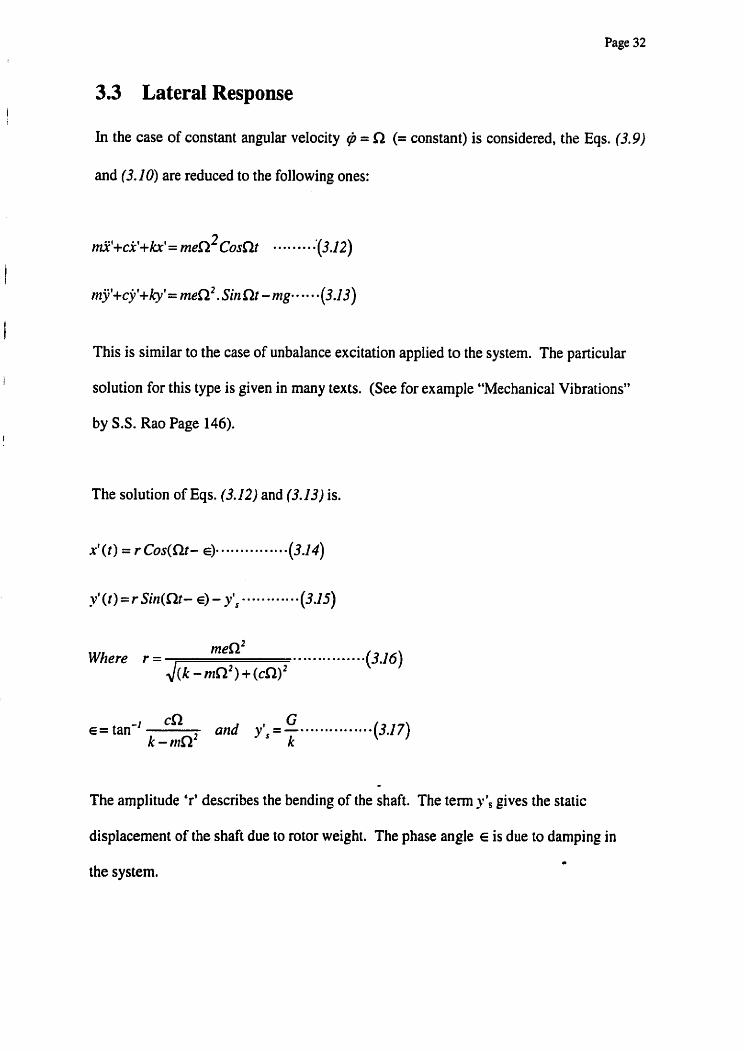
3.3 Lateral Response
In the case of constant angular velocity @ = R (= constant) is considered, the Eqs. (3.9)
and (3.10) are reduced to the following ones:
I This is similar to the case of unbalance excitation applied to the system. The particular
! solution for this type is given in many texts. (See for example "Mechanical Vibrations"
by S.S. Rao Page 146). I
The solution of Eqs. (3.12) and (3.13) is.
Where r = menZ ............... (3.16)
J(k - nrR2) + (cn)'
E = tan" cC2 G ajld y', = -...............
k - r l t ~ ' k (3.1 7)
The amplitude 'r' describes the bending of the shaft. The term y; gives the static
displacement of the shaft due to rotor weight. The phase angle E is due to damping in
the system.

Page 33
The graphical representation of the shaft center motion can be shown as follows.
Figure 3.4 : Disk center motion
The shaft center 0' is moving with angular velocity a in a circle of radius r and center
0, the point of static equilibrium. The displacement 'r' and E remains constant.
Let us introduce a new variable
Then by substituting it in Eqs. (3.14) and (3.25) we obtain
Xt= r Cosa ............... (3.1 9 )
and
y = r Sin a - Y', * * * * * * * * * (3.20)
Now Eqs (3.12) & (3.13)' using x' and y' from Eqs. (3.19) and (3.20),
can be written in terms of ' r 'and 'a 'coordinates

Page 34
Figure 3.5 : Polar and Cartesian Coordinates
These equations are further simplified by multiplying Eq. (3.21) by Sirla and Eq. (3.22)
by Cosa and then subtracting and summing up the results. The final equations then take
the form
By substituting x'= r Cosa, and y'= r Sina - y', in Eq. (3.1 I) it is obtained
kre Sin E - cre COS E + ky', e Cosp = r(t)
Recalling that Ayt, = nlg, and p = a, the latter is reduced to
kre Sir1 E - ere COS E + 1 g . e Cos(lb) = r(t) ..,......... (3.25)
In Eq. (3.23 the first two terms on the left hand side are constant terms. These constant
terms occur due to damping.
l f there i s no damping Sin E will always be zero.
Page 35
The third tern on the left hand side is an oscillatory term. This oscillating part originates
from the unbalance weight of the disk. For a vertical shaft this term will be zero. For a
well balanced rotor with a small eccentricity, the oscillating torque will be very small
compared to the driving torque.
Thus required torque consists of to parts; a constant part and a oscilhti~tg
part with frequency R
3.4 Conclusion
A single disk rotor system with an eccentric mass 'm' rotating at frequency R generates
an unbalance force of men2. This force causes the system to oscillate in rectilinear
directions. In addition to this a torsional forces of magnitude 'mge' oscillating with
frequency 0 is generated.

Page 36
CHAPTER 4
ANALYSIS MODEL I1 - TWO DISK ROTOR SYSTEM
Analysis of a two-disk rotor model is presented in this Chapter. Two unbalanced disks of
masses ml and m2 mounted on a mass-less shaft are considered for this model. The
center of masses of the disks are offset by eccentricities el and e2 from the center axis of
the shaft. When the rotor is rotated, as explained in the single disk rotor system, the shaft
bends and whirls around the axis of bearing centers. When an external torsional force is
applied to a disk, the torsional oscillations of the eccentric mass are coupled with the
lateral vibrations of the system and induce a coupled torsional-lateral vibration on the
rotor assembly. The two-disk rotor model differs from the single disk rotor model
because the relative twist between the two disks causing an additional oscillating torque
on the rotor system.

Page 37
4.1 Two Disk Rotor Model
Figure 4.1 shows the model of the two-disk-rotor system. The disks are fixed on
a mass-less shaft supported on two rigid bearings. The center of masses of the
disks are offset by eccentricities el and e2. The system is defined by six
independent coordinates. Similar to the single disk rotor assembly, each disk is
defined by two Cartesian and one angular coordinate.
Assumptions: Stiffness in both X and Y directions are the same.
The weights of rotors are G1=mlg and G2=m2g
Damping in both directions X and Y are the same.
Figure 4.1: Two eccentric disks mounted on a mass less shaft
Figures 4.2 and 4.3 shows the deflection of the shaft and the coordinate systems
used for defining the configuration. When the rotor rotates the shaft bends and
rotates around the axis of bearing centers. The rectilinear and mgular coordinates
used for defining the system are described below.

Page 38
Generalized Cartesian coordinates considered are as foIlows.
Figure 4.3: Cartesian coordinates of two-disk rotor system
0 is the axis of rotation of the shaft, 0' is the axis of rotation of the disk, and 0
is the mass center of the disk. The coordinates of 0' are (xt1y ') and the
coordinates of 0" are (X. Y). The angle of rotation of the center of mass of the
disk is p . Considering the Cartesian coordinate system, the generalized
coordinates for the two disks can be defined from x', , y', , p, and x', , y', ,p, or
from X, , &, 9, and X, , Y, , 9, coordinates for disks 1 and 2 respectively.

Page 39
Figure 4.4: Generalize coordinates and dimensions of two-disk rotor system
Disk 1. -
XI = x', + el Cos p,
Y, = yo, + el Sin p,
X2 = x', + e2 Cosp2
Y, = y', + e, Sinp2

Page 40
Applying Lagrange's equation
Le tT=K.E . , n = P.E. and V = D . E .
3 = Torsiorla1 Sifizess of the shafr.
Lugrange's equutiorl is given by
The motion of the two disks is described in generalized coordinates
x,,y,p, andX,,I:,p,
Kirtetic Erlergy
I 1 I I I P.E. = 17 = - F x' +? F1,yt, + rn,gY, +- F x' +- F2,y1,+n~t2gY, +-3(p2 - p,)2--*-(4.2)
2 " 2 2X ' 2 2
The forces associated with shaft displacements are
FIX = k x' +k x' ............... I 1 1 12 2 (4.3)
F,, = k y' +kXyt ,.... ........... 21 I (4.6)
Where klr, k12 etc. are shaft stiffness at corresponding disk locations.

Page 4 1 1
Substitution of Eqs. 3,4,5 and 6 in Eq.2 gives
Dissipation Energy
1 2 1 2 1 I D.E. = V = -cit1 +- jtl + - C X ' ~ + - C ~ ' : 2 2 2 2
Taking into account that
xtI = X, - e, Cusp,, y', = Y, -el Sinp,
and xt,= X2-e , Cosp,, y',=Y,-e2 Sinp,
Solving with respect to x, coordinate gives
n + ( f ,-e, Sirzp1.$5, -el ~ o s p , . $ : ) +ci',+k,,x',+k,,xt2 = 0
- 2 ~x',+cxt ,+k, ,xt l+k, ,x' , = nqe,@, Sinp, +rn1e,p, C o s p l ~ = ~ ~ ~ = ~ - - - ~ - - ~ ~ ~ ~ ~ ~ ~ ~ (4.1 0 )

Page 42
And the coordinate y'! is
Lagrange' s equation for generalized p, coordinate is given by
Solving with respect to p1 coordinate
I,@, +ex', e,Sinp, - j', e,Cosp, + k,,x', e,Sinp,
+k,,x9, e,Sinp, - k,,y', e,Cosp, - kI,y1, e,Cosp, - 3(p2 -pl) = T, ( ? ) * g * - * - - O - (4.1 4)
The equations of motions derived for disk 1 is given in (4. lo), (4.12) and (4.14). Similar
to these the equations of motions for disk 2 can be written as follows.
For the lateral motion of disk 2
For the torsional oscillations of disk 2

Page 43
The six equations of motions for coupled torsional and lateral vibrations of two disk rotor
system together below are;
I ,@, +cx', e,Si)zp, - j', e,Cosp, +k,,x', e,Sinp, +kI2x1, e,Sinp, - k, ,y', e,Cosp, - k,,yt2 e,Cosp, - 3(p2 - 9,) = T, ( t ) - - m - * - n - * (4.1 4)
1 7 1 ~ ~ ' ~ + j ' , +k2,y',+k2, y', +m?g = -4e ,$ , Cosp, + 11+e2@i Simp2- - - + - (4.1 6)
As it is seen from the above equations they are coupled and non-linear. Even if a known
function of p(t) is used the lateral oscillations will have a static coupling. Thus in order
to solve this non-linear coupled system a numerical solution method was applied.

Page 44
The equations were formed into a 6 x 6 matrix. The input parameters of the matrix are
defined as;
m, = Mass of disk 1
m, = Mass of disk 2
I, = Polar Moment of Inertia of disk 1
I, = Polar Moment of Inertia of disk 2
e, = Eccentricity of mass center of disk 1
e, = Eccentricity of mass center of disk 2

Page 45
c = Internal damping coefficient of rotor shaft
k,, , k,, , k,, , k, = Lateral shaft stiffnesses at disk locations (direct and cross)
They are calculated from the flexibility matrix as follows.
Refer to figure 4.1
1, = distance from first bearing support to the first disk
I, = distance between two disks
1, = distance from second disk to the second bearing support
L = Total distance of the shaft = 1, + I, + I ,
E = Modulus of Elasticity
z x rotor diameter' I = Moment of Inertia of the shaft =
64
z x mod ulus of rigidity x shaft diameter' 3 = Torsional stiffness of shaft =
32 x shaft length

Page 46

Page 47
4.2 Method of Solution
The matrix form of the six equations of motion is shown on page 46. To solve these
nonlinear coupled equations a solver program from Numerical Recipies was used.
The numerical solver program was based on the Newmark integration scheme. A
complete detail of the program is found in the reference text. (Wilson 1994). The
program was provided by Rotor Bearing Technology and Software Inc. in USA.
The output of the solver program computes a time base response of lateral and torsional
oscillations of the shaft. These output data are then plotted to represent the time
waveform of torsional and lateral vibrations of the shaft. The time waveform is then
converted to a spectra by Fourier transformation.
To plot the time waveform and frequency spectra of lateral and torsional vibrations a
plotter program from-Advanced Rotating Machinery Dynamic Software was used. Prior
authorization to use the plotter program was obtained from Rotor Bearing Technology
and Software Inc. in Pennsylvania.
The analysis was based on two parts. In the first part the frequency response of lateral
and torsional vibrations were computed for different rotational speeds and torsional
excitations of the rotor.. The time waveform an> spectra for each case was plotted and the
coupled torsional-lateral vibration frequencies were tabulated.

Page 48
The objective of the second part of the study was to determine the response behavior of
coupled torsional-lateral vibration at natural frequencies of the rotor. When the lateral
and torsional are de-coupled the natural frequencies of the system were initially
computed from the Mathematica program. Then the rotational speed of the rotor was
held constant and the frequency of the torsional vibration was increased until the coupled
torsional-lateral vibrations coincide at the natural frequency of the rotor. The amplitudes
of the coupled torsional-lateral vibrations were tabulated for all torsional excitations.
This analysis was performed for two different cases.
4.3 Two disk rotor model dimensional data
Rotor dimensions as per figure 4.4
Rotor Length = L = 1.0 meter
I, = I, = 0.3 meters; I, = 0.4 meters;
Diameters of disk I = disk 2 = 0.769 meters = 30.0 inches
Thickness of disk 1 = disk 2 = 0.038 meters = 1.5 inches
Diameter of shaft = 0.154 meters = 6.0 inches
Material properties of shaft and disk; Density = 7.68 x 1 0A3 kg/mA3
Modulus of Elasticity = 2 x 1 OA1 1 Pa
Modulus of rigidity = 72 x 10A9 Pa
The concentrated masses of the two disks and the lateral and torsional stiffness of the
shaft are computed from the 'Mathematica Program'.
A copy of this program with details is given in Appendix C1.

Page 49
The computed mass elastic properties are as follows.
Mass of disk 1 = mass of disk 2 = 138.723 Kg
Polar moment of inertia:
Disk 1= Disk 2 =10.2544 ~ g - m 2
Lateral Shaft Stiffness k,, = k , = 1.25264 x 10'
k,, = k,, = -1.0481 x 10'
Torsional Stiffness
3 = 3.97572 x 1 O"
These values were input into the Numerical solver program and the analysis was
performed in two parts. The first part of the analysis was to determine the response
frequencies of the coupled torsional-lateral vibrations. The second part was to analyze
the coupled torsional-lateral vibrations at natural frequencies of the system.
4.4 PART 1 - ANALYSIS OF RESPONSE FREQUENCIES OF COUPLED
TORSIONAL-LATERAL VIBRATIONS.
The first part of the analysis was to determine the response frequencies of coupled
torsional-lateral vibrations of the two-disk-rotor assembly. At a selected steady rotational
speed the torsional excitation frequency of the rotor was varied and the response
amplitude of the lateral vibrations was computed as a time depended displacement or
velocity function and graphed as a time waveform plot. The Fast Fourier Transformation
spectrum of the time waveform was then processed and plotted. The frequencies of the
vibration components were tabulated in table 4.1. Ten case studies were performed to
verify the data.

Page 50
4.5 INPUT TEST DATA AND RESULTS
Disk 1 Disk 2
Mass: 138.723 Kg 138.723 Kg
Polar Moment of Inertia: 10.2544 Kg-mA2 10.2544 Kg-mA2
Eccentricity of mass center: 0.0038 m 0.0038 m
1.25264 x lo9 -1.0481 x lo9 Lateral Stiffness =
-1.0481 x lo9 1.25264 x lo9
Torsional Stiffness = 3.97572 x 10"
Torque Amplitude = 30,000 N-M
The computer input data sheets and the plotted waveforms and spectra of the test results
for all case studies are attached in Appendix A pages 80 through 9 1.
Case 1: Rotational Speed = 2000 rpm = 33.3 Hz
Torsional Excitation Frequency = 62.8 radtsec = 10 Hz
Coupled Lateral-Torsional Vibration Frequencies = 23.3 and 43.3 Hz
Reference lateral vibration response plot is in Appendix A, page 82
Case 2:Rotational Speed = 2000 rpm = 33.3 Hz
Torsional Excitation Frequency = 94.2 radlsec = 15 Hz
Coupled Lateral-Torsional Vibration Frequencies = 18.3 and 48.3 Hz
Reference lateral vibration response plot is in Appendix A, page 83.

Page 5 1
Case 3:Rotational Speed = 2000 rpm = 33.3 Hz
Torsional Excitation Frequency = 25 1.2 radsec = 40 Hz
Coupled Lateral-Torsional Vibration Frequency = 73.3 Hz
Reference lateral vibration response plot is in Appendix A, page 84.
Case 4:Rotational Speed = 2000 rprn = 33.3 Hz
Torsional Excitation Frequency = 3 14.0 radlsec = 50 Hz
Coupled Lateral-Torsional Vibration Frequency = 83.3 Hz
Reference lateral vibration response plot is in Appendix A, page 85.
Case 5: Rotational Speed = 2000 rprn = 33.3 Hz
Torsional Excitation Frequency = 376.8 radtsec = 60 Hz
Coupled Lateral-Torsional Vibration Frequency = 93.3 Hz
Reference lateral vibration response plot is in Appendix A, page 86.
Case 6: Rotational Speed = 3000 rprn = 50.0 Hz
Torsional Excitation Frequency = 62.8 rad/sec = 10 Hz
Coupled Lateral-Torsional Vibration Frequencies = 40 and 60 Hz
Reference lateral vibration response plot is in Appendix A, page 87.
Case 7: Rotational Speed = 3000 rprn = 50.0 Hz
Torsional Excitation Frequency = 125.6 radfsec = 20 Hz
Coupled Lateral-Torsional Frequency = 30.0 and 70 Hz
Reference lateral vibration response plot is in Appendix A, page 88.

Page 52
Case 8: Rotational Speed = 3000 rpm = 50.0 Hz
Torsional Excitation Frequency = 376.8 radsec = 60 Hz
Coupled Lateral-Torsional Frequency = 1 10.0 Hz
Reference lateral vibration response plot is in Appendix A, page 89.
Case 9: Rotational Speed = 3000 rpm = 50.0 Hz
Torsional Excitation Frequency = 439.6 radisec = 70 Hz
Coupled Lateral-Torsional Frequency = 120.0 Hz
Reference lateral vibration response plot is in Appendix A, page 90.
Case 10: Rotational Speed = 3000 rpm = 50.0 Hz
Torsional Excitation Frequency = 502.4 radlsec = 80 Hz
Coupled Lateral-Torsional Vibration Frequency = 130.0 Hz
Reference lateral vibration response plot is in Appendix A, page 91.

Page 53
The data are tabulated as follows.
Table 4.1
I Rotational Speed in Hz
33.3 Hz
The column 1 and 2 in the above table are the frequencies of the forcing functions. The
column 1 gives the frequency of the lateral excitation force caused by the imbalance of
the rotor, and the frequencies of the torsional excitation force are tabulated in column 2.
Column 3,4 and 5 are response frequencies of the lateral vibration components. Column
4 gives the response due to the imbalance excitation of the rotor. Frequencies at column
3 and 5 are due to the modulation of imbalance excited vibrations at torsional excitation
frequency of the rotor. This shows that if a lateral vibration is occurring at w and a
Torsional Excitation
50.0 Hz
Lateral vibration response frequencies Hz
frequency in Hz
10.0 Hz
80.0 Hz
1
23.3 Hz
-
2
33.3 Hz
3
43.3 Hz
50.0 Hz 130 Hz.

Page 54
torsional oscillation is occurring at at the coupled torsional-lateral vibrations will occur
at frequencies f w ~ .
4.6 Part I1 - Response analysis of the coupled torsional-lateral vibrations at
natural frequencies of the rotor
In the second part of the study the response amplitude of coupled torsional-lateral
vibrations at the natural frequencies of the rotor was analyzed. In order to perform this
the coupled torsional-lateral vibration frequency was varied through a frequency range
around the natural frequency of the rotor. The amplitude of the coupled torsional-lateral
vibration was tabulated.
The natural frequencies of the rotor were first computed from a program built from
"Mathematica". Same dimensions of the model and mass and stiffness matrix obtained
from the previous program were used. The computed natural frequencies of this
model are at 193.257 Hz and 648.156 Hz. Details of the program are given in
Appendix C2.
Two case studies were performed. First the rotational frequency of the rotor was held at
3000 rpm = 50 Hz, and to assess the effect of coupled torsional-lateral response in lateral
mode, the frequency of the torsional oscillations were varied from 700 rad/sec to 1200
radfsec. The amplitudes of the coupled vibration components occurred at the frequency
o, + w, were tabulated. The waveform and spectrum data of the computed results are
attached in Appendix B 1 and B2.

Page 55
Case. 11 : Rotor Speed = 3000 rpm = 50 Hz
Table 4.2
Amplitude of coupIed vibration frequency
Rotor Speed Wr
meters
.36 0.9
The graph of torsional excitation frequency vs the amplitude of the lateral coupled
response frequency of Case 11. is shown on plot 4.1 page 56. The Y axis represent the
amplitude of the coupled torsional-lateral vibration measured in lateral mode.
Rad/sec Hz
Torsional Excitation Frequency w,
The torsional oscillation frequency was varied in the frequency range 1 I 1 Hz through
19 1 Hz to assess the affect of coupled torsionai-lateral vibrations when passes through
the 1" natural frequency of the rotor, at 193 Hz, as calculated from "Mathematica"
program attached in Appendix C2.
Coupled Torsional and Lateral vibration frequency a, + w,

Page 56

Page 57
The test similar to case 11 was repeated in case 12 at a higher rotational speed of the
shaft.
Case 12.: Rotor Speed = 3600 rpm = 60 Hz
Table 4.3
Rotor Speed o r
Coupled Torsional Amplitude of coupled 1 :z: A and Lateral 1 vibration frequency , mils Frequency o, vibration
frequency m, + m, 10- meters
The graph of torsional excitation frequency vs the amplitude of the lateral coupled
response frequency of Case 12. is shown on plot 4.2 page 59. The Y axis represent the
amplitude of the coupled torsional-lateral vibration measured in lateral mode.
4.7 CONCLUSION
1. When a rotor with mass imbalance rotating at speed rn is excited at a torsional
frequency of w f a coupled torsional-lateral vibration will be induced in the
system. The coupled torsional-lateral vibrations will occur at #, f a,. This
vibration will be in addition to the lateral vibration of the rotor, due to imbalance I
of the disk at or.

Page 58
2. The coupled torsional-lateral oscillations will excite the rotor at their natural
frequencies.

Frequency Response Function Coupled Torsional-Lateral Vibration in Lateral Mode
Rotor Speed - 3600 rpm
200 400 600 800 Torsional Excitation Frequency in radlsec
(Refer to table 4.3) Plot: 4.2

Page 60
CHAPTER 5
ANALYSIS OF EXPERIMENTAL DATA
In Chapters 4 and 5 single and two disk rotor systems were modeled and analyzed.
Nonlinear, coupled equations of motion involving torsional and lateral vibrations of the
systems were solved numerically. The lateral responses of shaft vibrations were
computed and tabulated.
The analyses concluded that in imbalance rotors the torsional and lateral vibrations are
coupled. When an unbalanced rotor is rotated at a frequency u , and excited from a
torsional oscillation at a frequency a, a coupled torsional-lateral vibration is induced at
frequencies or k a, . The coupled torsional-vibrations can excite the rotor at their
natural frequencies and cause resonance.

Page 61
In this chapter we will analyze the experimental data that were already acquired from an
industry rotor and compare this data with the above findings. A two-stage pump rotor
driven from a variable frequency drive motor was selected for this analysis.
Figure 6.1 on page 69 shows a rotor model of a two-stage Bingham pump impeller
assembly. The pumps are used in major pipeline companies to pump raw and processed
oil across Canada. The pump has two six-vane impellers and is center supported on
journal bearings.
The pump is driven from a 4000 Horsepower induction motor, powered through an
adjustable speed drive unit. The adjustable speed drive was a current source inverter
type variable frequency drive unit. These two-adjustable speed drives operate by varying
their excitation frequency supplied to the motor. During the process of frequency
conversions high torsional oscillations are generated in these drives. There are many
technical papers published with respect to this subject, for example refer to "Torsional
vibrations resulting adjustable speed drive units" by David Sheppard (1988).
The selected data used in the project is from a pump in a major pipeline company in
Alberta. When this pump was commissioned in January 1995 an unusual chattering noise
was heard emanating from the coupling and- the author was called upon to test and
analyze the vibrations. A series of tests including casing and shaft axial vibrations,
pressure pulsation, acoustic and current measurements of the pump were performed. The #
pump speed was ramped through the speed range from minimum speed 1440 rpm to 3960

Page 62
rprn and the transient vibrations were captured. During the ramp up the coupling motion
was frozen from a triggered strobe light, and this motion was filmed for further analysis.
All test data directed to a possible torsional resonance of the system. A conventional
torsional test using strain gauge techniques were performed to verify the findings.
The tests confirmed that high torsional vibrations are generated from the variable
frequency drive and excited the rotor at 6x rprn order of the pump. When the torsional
forces coincide the 2nd torsional natural frequency of the rotor resonance occurred. The
coupling chatter occurred during the torsional resonance of the rotor assembly.
The plots on pages 65 and 66 are torsional oscillation data, which include a detail
waveform plot and a cascade plot of torsional vibrations of the system. The detail
waveform plot gives a digitized real time waveform, of the measured vibrations, in a
specified speed range. The cascade plot gives corresponding spectra at each time sample
in the detail waveform.
The 6x rprn order oscillations exciting the rotor at the resonance frequency is shown on
the plots. The confirmed that torsional resonance of the rotor is at frequency 270 Hz.
The 6x rpm order is refer to as six times the running speed of the rotor.
The plots on pages 67 and 68 are cascade and detail waveform plots of bearing housing
vibrations, acquired on the outboard end bearing of the pump. The cascade plot shows

Page 63
occurrence of ix rprn order vibrations due to slight mechanical imbalance, 2x line
frequency electrical induce vibrations and 6x rpm order vane passing frequency
vibrations of the pump. The 6x rprn order vibrations peaked at the frequency 321 Hz and
this was a resonance condition.
The resonance around 320 Hz has been found in the past in many pumps of this
configuration. They have been confirmed through tests, and sufficient data are available
to prove their existence.
The most important fact that can be noted on the plot is excitation of the 7x rprn order
vibration at 321 Hz. This was an unusual peak that excited this rotor assembly at the
same resonance frequency of the pump. As the pump has six impellers only there are no
other excitation forces occurring on the unit at this speed.
As mentioned earlier this pump rotor has severe torsional excitation from the variable
frequency drive occurring at 6x rpm order of the rotor. The imbalance excited lateral
vibrations are also occurring at l x rpm of the pump rotor. The imbalance excited
vibrations couple with the lateral vibrations, induced a coupled torsional-lateral
vibrations on the unit, at 7x rprn order of the pump. This 7x rpm order coupled torsional-
lateral vibration excited the rotor at 321 Hz, which was a known resonance frequency of
the unit.

Page 64
To verify the natural frequencies of the rotor assembly an analytical study of natural
frequencies was performed. Advanced Rotating Machinery Dynamic software of Rotor
Bearing Technology and Software Inc. was used to compute the damped natural
frequencies of the system. A detail calculation of the model is attached in Appendix Dl.
The first three lowest damped natural frequencies and mode shapes are attached on pages
70 through 72. In the calculated model the damped natural frequency of the third mode
occurred at 323.5 Hz. Refer to plot on page 72.
The pump rotor was a complex model and it had many degrees of freedom. The coupled
torsional-lateral vibration excited the rotor at a higher frequency, i.e. at the third flex
mode of the rotor. As in this study the coupled torsional-lateral vibration was analyzed
through a simple two-degree-of freedom model we could not simulate the pump rotor
through our program to analyze the qualitative properties of the experimental system.
The experimental data verified the findings that were concluded in Chapters 4 and 5. As
the rotor imbalance was low the coupled torsional-lateral vibrations did not show at the
other frequencies. However, the coupled torsional-lateral vibrations excited the rotor at a
resonance frequency of the rotor.
The 7x rpm order refers to as seven times the running speed of the rotor.

Page 65
Cursor
Channel X : TORQUE 5880 e 80 Y
RPM: ???
70.512 . 70.762 71.012 CH-X<Twf): Tine I n Seconds
FFW: 268a8888 t -
WP Save
Torsional oscillations at 6x rpm order Of the pump peaked due to resonance
Plot 5.1 : Detail waveform plot of torsional oscillations
Upper: Detail waveform plot
Lower: Spectra and waveform at cursor location
Speed ramped up from 1440 rpm to 3690 rpm.

Page 66
i00.08 LB-FT
I
6x rpm order torsional oscillations peaked at 270 Hz. Torsional resonance occurred
TORQUE IN FT.LI \
4 82 1 6 1 239 318 396 Fmquency I n Hz
Tine; 72.88 Frcquencg; 270 f i ~ p l i t u d e : 1892 RPH . ??? Order . ???
B - 4 B - B Setup Uebtflxs H O F Z ~ C S S e t W k T~ace Curnos Ful lScr
Plot 5.2 : Cascade plot of pump torsional oscillations
Torsional oscillations occurred at 6x rpm order of the pump and peaked at 270 Hz.

Page 67
1 x rpm order vibrations
Pump utborrd Horizontal a 6x rprn order vibrations at vane passing frequency of the pump peaked at 32 1 Hz
/
Setup
7x rpm order coupled Torsional-Lateral vibrations Peaked at 321 Hz
Plot 5.3 : Cascade Plot of Pump Outboard Horizontal Vibration
Note the increase of vane passing frequency vibration at 32 1 Hz due to resonance, and
the 7x rpm order vibration peak also appeared only at 32 1 Hz. The torsional oscillations
at 6x rpm order, coupled with the lateral vibration at 1 x rprn order, induced a coupled
torsional-lateral vibration at the 7x rpm order of the pump. There are no other 7x rpm
order lateral vibration forces occurring in the pump as these are direct driven centrifugal
units, and the hydraulic forces are at vane passing frequency, at 6x rprn order of the
Pump-

Page 68
8,8888 53.97 11i.9 169.9 227.9 285.8 343.8 481.8 45rPB8.7 Tine I n Seconds
1.8~
136.641 136.891 CH-X<Twf>: Tine I n Seconds
m - Clr Aug Add Rug Segment Envelop Nxt Pnt
7x rprn order vibration: Coupled Torsional-Lateral At frequency 32 1 Hz
Plot 5.4 : Detail Waveform Plot of Pump Outboard Horizontal Vibration
Upper plot : A detail time waveform of pump vibration. Cursor located at speed 2759
rpm. The lower plots are spectrum and time waveform corresponds to the speed at cursor
location, (i.e at speed 2759 rpm). At this speed the 7x rpm order vibration peak occurred
at 321 Hz. This plot corresponds to the cascade plot on p a p 7 1 . Speed ramped up from
1440 rprn to 3960 rpm.
'Nx rprn order' refers to N times the running speed of the unit.

@ 005/005
Page 69

Mode 2 of 6 23265E+04 CPM
,882 F
Plot 5.6: First Bending Mode of the Pump Rotor
At 38.7 Hz.

Page 71

Page 72

Page 73
CHAPTER 6
CONCLUSIONS AND RECOMMENDATIONS
The influence of coupled torsional-lateral vibrations on rotor bearing assemblies was
analyzed in this study. The results concluded through analytical modeling were verified
by experimental data that were already performed on an industry rotor model. The
response frequencies of the coupled torsional-lateral vibrations, the effect of coupled
torsional-lateral vibration at lateral natural frequencies of the rotor were investigated, and
the parameters that influence this coupling were studied.
When a rotor with a mass imbalance of 'nte' is rotated at a speed of w , a lateral
vibration of magnitude mew: is generated, where 'e ' is the eccentricity of the imbalance
mass 'm'. This imbalance excited lateral vibration occurs at the same rotational

Page 74
frequency of the rotor. In addition, a torsional vibration of magnitude 'mge ' is also
induced, due to this imbalance force, at the same rotational frequency of the rotor. The
magnitude of the lateral vibration increases as a square of the speed, but the magnitude of
the torsional vibration remains constant at all speeds. Thus the imbalance induced
torsional vibrations of the system are weak compared to the lateral vibrations.
When this imbalance rotor is excited by an external torsional oscillation, the torsional
oscillation will couple with the lateral vibration of the system and induce a coupled
torsional-lateral vibration. The torsional oscillation will modulate the lateral vibration,
and the induced coupled torsional-lateral vibration will occur at rotational frequency 2
torsional frequency of the rotor.
When the frequency of the coupled torsional-lateral vibrations approach the lateral
natural frequency of the rotor the vibration response of the system increases to a
maximum. The induced coupled torsional-lateral vibrations excite the rotor due to
resonance.
The magnitude of the coupled torsional-lateral vibrations depend on the eccentricity of
the imbalance mass. Since in many rotors the imbalance mass is small, the magnitude of
the coupled torsional-lateral vibration remains weak. The parameters that affect the
coupled torsional-lateral vibrations in a rotor system are:
Magnitude of the imbalance mass
Magnitude of the torsional oscillation forces.

Page 75
Damping coefficient of the rotor disk assembly.
In geared rotor systems the torsional and lateral vibrations are coupled due to nature of
their geometry. The torsional moments in gears are transmitted through tooth force. The
transverse forces and bending moments are generated from these torsional moments.
In contrast to the geared rotor systems, in rotor disk assemblies, the torsional and lateral
vibrations are coupled only if a large imbalance is present in the system, but still this
coupling tends to be weak. However, if an external oscillating force of higher magnitude
is applied to the rotor, the coupled torsional-lateral vibrations grow stronger and increase
the response characteristics of the system. Thus when designing systems, particularly
those being driven through variable frequency drive (VFD) motors, where torsional
oscillations are present, special care should be taken to minimize the imbalance occurring
in rotors.
In classical linear vibration analysis the affects of coupling between the torsional and
lateral vibrations are ignored. Current rotor dynamic analysis tools also treat lateral
deformations, associated with shaft bending, and torsional twisting as independent of
each other and the systems are considered to be statically and dynamically decoupled.
On the other hand, for rotors subjected to rotatipg unbalance or lateral forces, studies of
dynamic response are performed by focusing on the lateral vibration aspect only.
Similarly, the systems where torsional forces are considered predominant, torsional
response analysis is carried out independently of lateral vibrations. This assumption may

Page 76
appear reasonable in many applications. However, requirements for high speed, high
power transmission and lighter rotors may require that the coupling between lateral and
torsional oscillations is taken into account, since ignoring this coupling may lead to
inaccurate and misleading dynamic predictions.

Page 77
Bibliography
Corbo, M. A. & Malanoski, S.B., (1996) Practical Design Against Torsional Vibration,
2jth Turbomachirtery Symposium, Texas A &M University, Texas.
Grgic, A*, Heil, W., & Prenner, H., (1992) Large Converter-Fed Adjustable Speed AC
Drives for Turbomachines, Proceedings of ?he 21" Turbornachinery Symposium,
Texas A M Llniversiry. P 103-1 12
Hudson, J. H., (1992) Lateral Vibration Created by Torsional Coupling of a Centrifugal
Compressor System Driven by a Current Source Driver for a Variable Speed
Induction Motor, Proceedirlgs of the Twertpj7rst Turbontachinry Symposium,
Turbontacltinery horatory, Department of Meachanical E~lgineerirtg, Texas
A &M University, College Station, Texas ( 1 992)
Iida H., Tamura, A. & Oonishi, M., (1984) Coupled Torsional-Lateral Vibration of a
Shaft in a Geared Rotor System II, Bulletin of JSME, Vol28, No 245, Deceruber
1985.
Iida, H., Tamura, A. & Yamada, Y., (1978) Coupled Torsional-Lateral Vibration of a
Shaft in a Geared Rotor System I, Bulletirl of JSME, Vol23, No 186, December
1980.
Iwatsubo, T. & Nan, H., (1 989) Coupled Lateral-Torsional Vibration of a Rotor System
trained by Gears ( ldh Report. Noise Measurement by Sound Intensity Method),
Transaction of the Japan Society of Mechartical Engineers, Part C v n 518 Oct
1989, p 252702532. ISSN: 0387-5024.

Page 78
Kishor, B. & Gupta, S.K., (1989) On Dynamic Gear Tooth Loading Due to Coupled
Torsional-Lateral Vibrations in a Geared Rotor Hydrodynamic Bearing System,
Publication it Journal of Tribology, January, 1989.
Kramer, E., (1993) Dynamics of Rotors and Foundations, Springer-Verlag, Berlirl
Heidelberg, New York (1 993)
Kuang, 3. & Tsai, J.H., (1991) Improved Branch Method for Gear-Coupled Systems,
Jourrzal of the Chinese Sociev of Mecha~zical Engirteers, v 12 n 2 Apr 1991 p
1 77-187, ISSM 0257-5'731.
Kuniyoshi, I., Yasuhiko, O., Akira, 0. & Hideaki, M.,(1990) Field Telemetry of Blade-
Rotor Coupled Torsional Vibration at Matuura Power Station No. 1 Unit,
Presentation at the Sixth Workshop on Rotordyr~arnic Instability Probler~ts irr High
Performance turbo machine^, May 21-23. 1990, Texas A&M University, Texas.
Mario, P. ( 199 1) Structural Dynamics Theory and Computation, Varl Nostrand Reinkold,
New York
Mitchell, L.D. & Mellen, D.M., (1975) ~orsional-~keral Coupling in a Geared, High-
Speed Rotor System, preserttation at Desig~z E~lgirteering Teclurical
Cor fererlce, Wasitir~gtorz D. C., September 1 7- 19, 1975, Design E~lgirleering
Division, ASME paper 75-DTE- 7.5
Nelson, H.D., Natsiavas, S. & Chin-Shong, C., (1993) Coupled Lateral-Torsional
Vibration of a Gear-Pair System Suppoged by a Squeeze Film Damper, ASME
Publication, Noit-Lirtear Vibratiorzs, LIE-Vol54.
Nelson, H.D., Shiau, T.N., & Chou, Y.W., (1994) Study on the Dynamic Characteristics
of Geared Rotor-Bearing System with Hybrid Method, ASME (Paper)

Page 79
Proceedings of the international Gas Turbine and Aeroeqine Corzgress arid
Exposition, June 13-1 6, 1994, Hague, Neth Publication by ASME New York, NY,
USA, p 1-11, Paper; 94-GT-355, ISSN: 0402-1215.
Rao, S.S ., (1990) Mechanical Vibrations, 2"d Edition, Addis011 Wesley Publish irtg
Company, New York (1 990)
Schwibinger, P. & Nordmann, R., (1987)The Influence of Torsional-Lateral Coupling on
the Stability behavior of Geared Rotor Systems, ASME Journal ofEngi~zeers for
Gas Turbine and Power, September 1987.
Sheppard, D. J., (1988) Torsional Vibation Resulting From Adjustable-Frequency AC
Drives, IEEE Transaction on Industry Applicntiorls, Vol. 24, No. 5,
September/Qctober 1988.
Steidel, R.F (1989) An Introduction to Mechanical Vibrations, Johrl Wiley & Sons, New
York (1 989)
Thompson, A. S., (1997) Advancements in Machinery Management using the
Measurement of Rotor Torsional Response, Prese~ltation at ASME ASIA 97
Congress & Exhibitiorz, Sep 30-Oct 1, 1997, Singapore, ASME Paper; 97-AA-128
ISSN 0402-1215
Thompson, W.T. (1988) Theory of Vibrations with Applications, Prentice Hall, New
Jersey, 3" Editior~
Timoshenko, S.P., Weaver, W. & Young, D.. (!990) Vibration Problems in Engineering,
Jolm Wiley and Sons, New York (1 990)

Page 80
Vance, J.M. & French, R.S., ((1984) Measurement of Torsional Vibration in Rotating
Machinery, Presentation at Design Engirzeering Techrzicul Corrfere~zce,
Cambridge, Massachusetts, ASME Paper No 84-DTE-55, June 15, 1984.
Vandenput, A., Geysen, W. & Belrnans, R. (1985) Influence of Torsional Vibrations on
Lateral Oscillations of Induction Motor Rotors, IEEE Trarzsactiorls of Power
Apperatus and Systems, VoZ PAS-1 04, No 7, July 1985.
Wachel, J.C. & Szenasi, F.R., (1980) Field Verification of Latera-Torsional Coupling
Effects on Rotor Instabilities in Centrifugal Compressors, NASA Conference
Publication No. 2147, 1980.
Wachel, LC. & Szenasi, ER., (1993) Analysis of Torsional Vibartions in Rotating
Machinery, Proceedings of the 2zd Turbonzachinery Symposiunz, Texas A &M
University, p 126- 151.
Wilson, E.L., & Bathe, K., (1990) Numerical Methods in Finite Element Analysis,
Prerztice Hall, New Jersey.
Yaman, Y. (1996) Vibrations of Open-Section Channels: A Coupled Flexural and
Torsional Wave Analysis, Journal of Sound and vibration (lPP7), v 204 n I , Jul3,
1997 ~131-158 -

Page 80
Appendix A
Computed lateral vibration response plots as per Case 1 through Case 10 of Chapter 4,
Section 4.5. are attached in this appendix. As the response in both directions are
symmetrical only one response plot per each Case Study is included.

Rota. inp Page 81
Two Disk Test File 7 150000 0.00010 100000 10 2000.0 9.8 138.723 10.2544 138.723 10.2544 0.038 0,000 5000. 1.25264e9 -1.0481e9 -1.0481e9 1.25264e9 3.97572e6 30000.0 62.8 0.0
0.0 0.0 0.0
Input Guide
LINE 1 : TITLE ( 7 2 CHARACTERS ) LINE 2:NUMB. OF DEGREES OF FREEDOM (ALWAYS 7 = 6 + 1 RIGID BODY ROTATION)
NUMB. OF TIME STEPS TIME STEP INCREMENT (DELTA T - SECONDS) NUMB. OF TIME STEPS TO SKIP BEFORE BEGINNING TO PRINT OUTPUT NUMB. OF TIME STEPS TO SKIP BETWEEN OUTPUT PRINTING (EVERY lOTH STEP) SHAFT SPEED (RPM) GRAVITY (M/SA2)
LINE 3:DISK #1 MASS (KG) DISK #1 POLAR INERTIA (KG-MA2) DISK #2 MASS (KG) DISK #2 POLAR INERTIA (KG-MA2)
LINE 4:DISK #1 ECC. FROM SHAFT CENTER TO CENTER OF MASS (M) DISK #2 ECC. FROM SHAFT CENTER TO CENTER OF MASS (M)
LINE 5:DAMPING FOR LATERAL BEAM BENDING
LINE 6:Kll LATERAL SHAFT STIFFNESS K12 LATERAL SHAFT STIFFNESS K21 LATERAL SHAFT STIFFNESS K22 LATERAL SHAFT STIFFNESS TAU TORSIONAL STIFFNESS
LINE 7:DISK #1 TORQUE AMPLITUDE (N-M) DISK #1 TORQUE FREQUENCY (RAD/SEC) DISK #1 TORQUE PHASE ANGLE (RAD) DISK #2 TORQUE AMPLITUDE (N-M) DISK #2 TORQUE FREQUENCY (RAD/SEC) DISK #2 TORQUE PHASE ANGLE (RAD)

P l o t : A1 - 1 \armdw\project\uoc\roP.rsg 23:38:30
Time Waveform
t Time (s)
c:\pro ra-I\arrndw\project\uoc\rot2.rsg 09128~~ 23:38:30 - Frequency Spectrum
@ 0 10 20 30 40 50 60
Frequency (HZ) Rotational Frequency 33.3 Hz. & Torsional Frequency 10.0 Hz.

P l o t : A2
Page
Time Waveform
u r 10 11 12 13 14 15 '' Time (s)
c:\pro ra-l\armdw\project\uoc\rot2.rsg 09/2818 23:58:30
Frequency Spectrum 7 I 1 1 1 1 I - - f -~ isk #I - Xdis 1
6
5
4 -
3 -
U) e C 1 (D
U) 1 0 e 0
0 D c 0 10 20 30 40 50 60 70
€5 Frequency Rotational Frequency 33.3 Hz. & Torsional Frequency 15.0 Hz.
I I I I I I I I I
- - - - I - - - - I - - - - I - -
I I I I 1 I
- - - + - - - . + - - - - I - -
I I I
I I I - - - T - - - -, - - - -
I I I
I I I 2 - - - - - - - - - - - - - - I I
I I I - - - . - - - - - - - - - - - - - - - - - - - - - - - - - . - - - ,
I I I I I I
- - I - - - - L - - - A ---,
I I I
I I 1 - - I - - + - + - - - - * - - - -
I I I
I 1 I - - I - - - - - ,- - - - - - -
I I I
I I I - - - - - - - - - - - - I _ _ _ _
I I
I I , I I I I I - . - - - - - - - - - - - . - - _ _ _ _ _ _ _ _ _ _ I I I I
I 1 I t A r i t -. -

Page 8 4
P l o t : A3 Time Waveform c:\pro ra-1 \armdw\project\uoc\rot2.rsg 09/2i'k8 22: 1 1 : 1 0
15 I I I I - ~ i s k #l - Xdls I
Time (s) Frequency Spectrum
1 1 I - fbisk # I - Xdi
o O ~ o h o n a l ~ # 8 ~ u e n c ~ 3% Hz. & Torsional PrequencJ80.0 Hz. Frequency (Hz)

Page 8 5
Plot: A4 Time Waveform cS\pro ra- 1 \armdw\project\uoc\rot2.rsg 69127b8 222744
D 2 -15 1 I 1 I I u c 10 11 12 13 14 15
Ez Time (s)
c:\pro ra-1\arrndw\project\uoc\rot2.rsg Frequency Spectrum 0~/27%8 22:27:44
0 c ' 0 10 %tationa%eque& 33.3 2. & ~ o f i o n a l ~ & u e n e ~ 8b.0 Hz. 90 E4 Frequency (Hz)

Page 86
Time Waveform c:\pr ra-l\armdw\project\uoc\rot2.rsg Plot: A5 0912% 22345: 12
15 I f 1 1 -Disk # 1 - Xdis 1
z 10
E2 Time Isl . . c:\pro ra-1 \armdw\projecRuoc\rot2.rsg Frequency Spectrum 09127838 2WEi: 12

Page 87
P l o t : A 6 Time Waveform 4 1 I 1 1 I -Disk #l - Xdis
I I I I
Lk Time (s)
c4pro ra- 1\armdw\projecAuoc\rot2.rsg 09129ba 00: 113:48
0 10
Frequency [Hz)
20
Rotational 30 40
Frequency 50.0 Hz. &
Frequency Spectrum 1 -$isk #1 - Xdis
I I
50
Torsional 60 70 80
Frequency 10.0 Hz.

Page 8 8
c:\pro ra- 1\armdw\project\uoc\rot2.rsg 09i28fb8 23:% 1 0
Plot: A 7 Time Waveform
11 12 13 14 15 Ef Time (s)
c:\pro ra- 1 \armdw\project\uoc\rot2.rsg 09128h8 23:50: 10 Frequency Spectrum
18
6 -
4 - U)
1 S g z % 0.
I ! 1 f 1 I - [bisk #l - Xdis
I I I I I I - - - 1 6 - - - - I - - - l - - - r - - - 1 - - - - l - - - - - I - - - -
I I 1 4 - - - - I - - - * - - - + - - - I - - - -
I I 1 2 - - - - - I - - - 4 - - - - 4 - - - I - - - - -
1 I
1 ( , - - - - L - - 1 - - - I I I I 0 - - - - - - - - - - - - - - - - - - I I I I
- - - - - - - - - I I I I
.- - - 1 - - -1 - - - - I - - - - I I
2 - - - - 1 - I - q - - - t - - - 1 - - - + - - - \ - - - - I I I 1
c 0 10 20 30 40 50 60 70 80 '= Frequency (Hz) Rotational Frequency 50.0 Hz. & Torsional Frequency 20.0 Hz.

Page 89
cS\pro ra- 1 \armdw\projecRuoc\rot2.rsg P l o t : A8 Time Waveform 09127b8 23:37:48
c:\pro ra- 1 \armdw\project\uoc\roi2.rsg 09/27h8 23:37:48
r Frequency Spectrum
d - c 0 20 40 60 80 100 120
Frequency (Hz) Rotational Frequency 50.0 Hz. & Torsional Frequency 60.0 Hz.

Page 90
P l o t : 89 Time Waveform
13 14 15
Frequency Spectrum 1 ! 1 1 --)-~isk #1 - Xdis
'' Frequency (Hz) Rotational Frequency 50.0 Hz. & Torsional Frequency 70.0 Hz.

Page 91
Plot: A 1 0 Time Waveform
E$ Time (s)
cS\pro ra- 1 \arrndw\project\uoc\ro12.rsg 69127k3 ZXjl: 18
18 Frequency Spectrum f I I 1 1 I + ~ i s k # 1 - Xdis f
Frequency ("4 Rotational Frequency 50.0 Hz. & Torsional Frequency 80.0 Hz.

Page 92
Appendix B1
Computed lateral vibration response plots as per Case 1 1 of Chapter 4, Section 4.6 are
attached in this appendix.

Rota. inp
i -
Page 92
Two Disk Test File 7 150000 0.00010 100000 10 3000.0 9.8 138.723 10.2544 138.723 10.2544 0.038 0.000 5000. 1.25264e9 -1.0481e9 -1.0481e9 1.25264e9 3.97572e6 30000.0 900.0 0.0
0.0 0.0 0.0
Input Guide
LINE 1:TITLE (72 CHARACTERS) LINE 2:NUMB. OF DEGREES OF FREEDOM (ALWAYS 7 = 6 + 1 RIGID BODY ROTATION)
NUMB. OF TIME STEPS TIME STEP INCREMENT (DELTA T - SECONDS) NUMB. OF TIME STEPS TO SKIP BEFORE BEGINNING TO PRINT OUTPUT NUMB. OF TIME STEPS TO SKIP BETWEEN OUTPUT PRINTING (EVERY lOTH STEP) SHAFT SPEED (RPM) GRAVITY
LINE 3:DISK #1 DISK #1 DISK #2 DISK #2
LINE 4:DISK #1 DISK #2
LINE S:DAMPING'
(M/SA2) MASS (KG) POLAR INERTIA (KG-MA2) MASS (KG) POLAR INERTIA ( KG-MA2 ) ECC. FROM SHAFT CENTER TO CENTER OF MASS (M) ECC. FROM SHAFT CENTER TO CENTER OF MASS (M) FOR LATERAL BEAM BENDING
LINE 6:Kll LATERAL SHAFT STIFFNESS K12 LATERAL SHAFT STIFFNESS K21 LATERAL SHAFT STIFFNESS K22 LATERAL SHAFT STIFFNESS TAU TORSIONAL STIFFNESS
LINE 7:DISK #1 TORQUE DISK #1 TORQUE DISK #1 TORQUE DISK #2 TORQUE DISK #2 TORQUE DISK #2 TORQUE
AMPLITUDE (N-M) FREQUENCY ( RAD / SEC ) PHASE ANGLE (RAD) AMPLITUDE (N-M) FREQUENCY (RAD/SEC) PHASE ANGLE (RAD)

Frequency Response Function of Coupled Torsional-Lateral Vibrations
600 700 800 900 1000 1100 1200 . 1 300 Torsional Excitation Fequency in radlsec
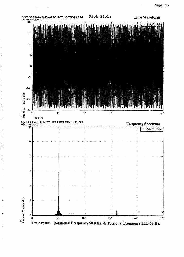
Page
CAPROGRA- I\ARMDW\PROJECT\UOC\ROTZ.RSG : 08/31/98 00:09: 10
Time Waveform
Time (s)
C:\PROGRA--I\ARMDW\PROJEC~UOC\ROT~.RSG 08r3 1/98 oo:og: 10 Frequency Spectrum
12 1 ! ! ! I -Disk # 1 - XclB
-
-
-
3
-
a 50 loo 150 2nc1 d
250
Frequency (Hz) Rotational Frequency 50.0 Hz. & Torsional Frequency 11 1.465 Hz.

Page 96
Time Waveform
Time (s?
3A-- 1 \ARMDW\PROJECnUOC\ROTZ.RSG )o:o5:1a Frequency Spectrum
1 I 1 ! 1 -Disk fi I - Xdi,
0
Frequency (Hz)
50
Rotational 1 00
Frequency 50.0 Hz. & 150 200
Torsional Frequency 250
127.388 Hz.

Page 97
C:\PROGRA- I \ARMDW\PROJECT\UOC\ROT2.RSG P1o 08131198 00:01:36
Time Waveform
C:\PROGRA-• ~\ARMDw\PROJEC~UOC\ROT~.ASG 081~1t98 00:01:36 Frequency Spectrum
! I ! ! I -Ursk # I - Xdi:
0
Frequency (Hz)
50 100 1 50 200 250
Rotational Frequency 50.0 Hz. & Torsional Frequency 135.35 Hz.

Page 98 L
C:\PROGRA- t\ARMDW\PROJECnUOC\ROT2.RSG p l o t B 1 . 4 08/:30/98 23:56:04
Time Waveform 25 I I I
C:\PROGRA--1\ARMDW\PROJECT\UOC\FIOT2.RSG OBi30198 ~3:3304 Frequency Spectrum
r I I I
2 O L 7 0
E 3 50 100 15u ~ n r J 2%~
Fwuency ( H z ) Rotational Frequency 50.0 Hz. & Torsional Frequency 136.943 Hz.

I Page 99
C:\PROGRA- l\ARMDW\PROJECnUOC\ROT8.RSG p l o t 8 1 5 08130198 23:49: 12 Time Waveform
C:\PROGRA--1\ARMDW\PHOJECnUOC\ROT2.RSG 08i30/98 23:49: 12 Frequency Spectrum
12 ! 1 ! 1 -Disk ti 1 - Xdis 1
0 50 100 150 %I10 250
F rwcncy (Hz) Rotational Frequency 50.0 Hz. & Torsional Frequency 138.535 Hz.

I Page 100
CAPROGRA- I \ARMDW\PROJECnUOC\ROT2.RSG P1o Time Waveform 08/30/98 23:44:34
13 1 4 15
Frequency Spectrum I ! D i s k .# I - Xdi
0 50 1 DO 150 200 250
Frequency (HZ) Rotational Frequency 50.0 Hz. & Torsional Frequency 139.331 Hz.

Page 101
C:\PROGRA- I\ARMDW\PROJECnUOC\ROT2.RSG 'lot 08i30198 23:40:02
Time Waveform
r c 10
Time (s)
C:\PROGRA- I\ARMDWPROJEC17UOC\ROT2.RSG 0 8 1 3 o i ~ 2340:02 Frequency Spectrum
1 I I I I -Disk H I - Xdis
C of- 0 50 I 00 150
E: F r e w e ~ . . ~ (Hz) Rotational Frequency 50.0 Hz. & Torsional Frequency 140.924 Hz.

Page 102
C:\PRQGRA- 1 \ARMDW\PROJEC~UOC\ROT2,RSG p l o t B 1 8 Time Waveform 08/30/98 2324: 18
4 r t I !
2 +L I I 1 I !- c 10 11 12 13 1 4 15
E,2 Time (s)
C:\PROGRA-- t\ARMDW\PROJECnUOC\ROT2.RSG 08~30198 2324: 18 Frequency Spectrum -
! I --Disk # 1 - Xtlis I
0 50 1 00 1 SO 200 2 50
F w l ~ ~ n w (Hz) Rotational Frequency 50.0 HZ. & Torsional Frequency 141.719 Hz.

Page 103 I
C:\PROGRA-1\ARMDW\PROJECT\UOC\ROT2.RSG ' lot B1 Time Waveform 08/30/98 23: 18~30
4 I I I ! I - ~ i s k N 1 - Xdis 1
13 I 4 15
Frequency Spectrum
0 50 100 150 200 250
Frewency (Hz) Rotational Frequency 50.0 Hz. & Torsional Frequency 143.312 Hz.
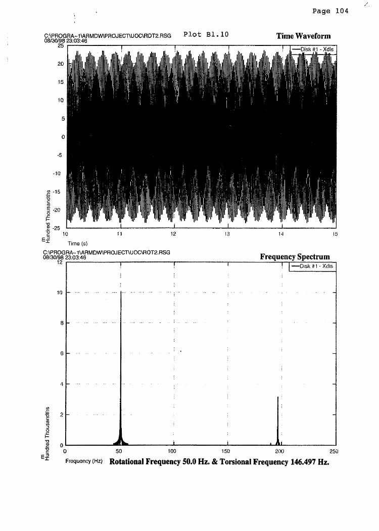
I Page 104
Time Waveform
C:\PROGRA-- l\ARMDW\PHOJECnUOC\HOT2. RSG 00/30/98 23:03:46
12 Frequency Spectrum
! I f ! 1 --Disk rY I - Xrlis I
0 50 100 1 50 200 25U
Frcw~ncy (Hz) Rotational Frequency 50.0 Hz. & Torsional Frequency 146.497 Hz.

Page 105
Time Waveform
a c 10
E' Time (s)
* - c 0 50 1 00 150 200 250
€2 Fretluenc~ (Hz) Rotational Frequency 50.0 Hz. & Torsional Frequency 159.236 Hz.

Page 106 I
CAPROGRA- l\ARMDW\PROJECT\UOC\ROT2.RSG p l o t B 1 1 2 Time Waveform 08130/98 22:46:38
1 I
C;\PROGRA-• 1\ARMDW\PHOJECT\UOC\HOT2.RSG 08;30/98 22:46:38 Frequency Spectrum
I I 1 I
0 50 too 150 200 250
Fmquency (HZ) Rotational Frequency 50.0 Hz. & Torsional Frequency 175.159 Hz.

Page
Time Waveform
'' Time (5)
C:\PROGRA--I\ARMDW\PROJECllUOC\ROT2.RSG 08/30/98 22:38: 18
Frequency Spectrum

Appendix B2
Computed lateral vibration response plots as per Case 12 of Chapter 4, Section 4.6 are
attached in this appendix.

Rot2. i n p
Page 109
Two Disk Test File 7 150000 0.00010 100000 10 3600.0 9.8 138.723 10.2544 138.723 10.2544 0.038 0.000 5000. 1.25264e9 -1.0481e9 -1.0481e9 1.25264e9 3.97572e6 30000.0 1000.0 0.0
0.0 0.0 0.0
Input Guide
LINE 1 : TITLE ( 7 2 CHARACTERS) LINE 2:NUMB. OF DEGREES OF FREEDOM (ALWAYS 7 = 6 + 1 RIGID BODY ROTATION)
NUMB. OF TIME STEPS TIME STEP INCREMENT (DELTA T - SECONDS) NUMB. OF TIME STEPS TO SKIP BEFORE BEGINNING TO PRINT OUTPUT NUMB. OF TIME STEPS TO SKIP BETWEEN OUTPUT PRINTING (EVERY lOTH STEP) SHAFT SPEED (RPM) GRAVITY (M/SA2)
LINE 3:DISK #I MASS (KG) DISK #1 POLAR INERTIA (KG-M"2) DISK #2 MASS (KG) DISK #2 POLAR INERTIA (KG-MA2)
LINE 4:DISK #1 ECC. FROM SHAFT CENTER TO CENTER OF MASS (M) DISK #2 ECC. FROM SHAFT CENTER TO CENTER OF MASS (M)
LINE 5:DAMPING FOR LATERAL BEAM BENDING
LINE 6:Kll LATERAL SHAFT STIFFNESS K12 LATERAL SHAFT STIFFNESS K21 LATERAL SHAFT STIFFNESS K2 2 LATERAL SHAFT STIFFNESS TAU TORSIONAL STIFFNESS
LINE 7:DISK #1 TORQUE AMPLITUDE (N-M) DISK #1 TORQUE FREQUENCY (RAD/SEC) DISK #1 TORQUE PHASE ANGLE (RAD) DISK #2 TORQUE AMPLITUDE (N-M) DISK #2 TORQUE FREQUENCY (RAD/SEC) DISK #2 TORQUE PHASE ANGLE (RAD)

Page 110

Page 111
C:\PROGRA- I\ARMDW\PROJECnUOC\ROT2.RSG p l o t B 2 . 1 Time Waveform 08/31/98 0'1 :27:52
r--
c 10
Ef Time (s)
C:\PROGRA- 1\AR MDW\PROJECnUUC\ROT2. RSG 08/31i98 01 :27:52 Frequency Spectrum
I 1 I ! ! I -Disk # t - Xdis ]
F r w e n c ~ (Hz) Rotational Frequency 60.0 Hz. & Torsional Frequency 11 1.465 Hz.

Page 112 "
C:\PROGRA- l\ARMDW\PROJECTWOC\ROT2.RSG 08/31/98 01 :36:22
Time Waveform
Time (s)
C:\PROGRA-?\ARMDW\PROJECnUOC\ROT2,RSG O8/3 1/98 01 :36:22 Frequency Spectrum
Frequency (Hz) Rotational Frequency 60.0 Hz. & Torsional Frequency 127.388 Hz.

- Page 113
C:\PROGRA- 1\ARMDW\PROJEC77UOC\ROT2.RSG p l o t B2 - 3 08/31/90 01 :45:00
Time Waveform 4 I f I -Disk #I - Xdis 1
6 g -4 I 1 1 1 I I c 10 1 1 12 I 3 I4 15
Eg Time (s)
CAPROGRA- l\ARMDW\PROJECnUOC\ROT2.RSG 08/31/96 01 :45:00 Frequency Spectrum
I I I
I ! I -Disk It l - Xdis 1
F rewncy (Hz) Rotational Frequency 60.0 Hz. & Torsional Frequency 130.573 Hz.

Page 114 L
C:\PROGRA-I\ARMDW\PROJECT\UOC\ROT2.RSG p l o t B a . 4 08/31/98 01 :50:02
Time Waveform
u c 0 SO 100 I 50 200 250
Fresuonc~ (Hz) Rotational Frequency 60.0 Hz. & Torsional Frequency 132.166 Hz.

7
Page 115
C:\PROGRA-l\ARMDW\PROJECT\UOC\ROT2.RSG p l o t 8 2 . 5 08/31/98 O't 5530
Time Waveform 5 1 I [ -Disk #I - Xdis I
,E -sl: 1 1 I I I c 11 12 13 I4 15 EE
Time {s! C:\PROGRA-- I\ARMDW\PROJEC~UOC\ROT2.RSG 06/31/98 01 :55:30 Frequency Spectrum
15 1 ! I -Dsk l l - Xdis I
Frw-~oncy (Hz) Rotational Frequency 60.0 Hz. & Torsional Frequency 132.962 Hz.

Page 11.8
C:\PROGRA- l\ARMDWROJECnUOC\ROT2.RSG P1o 08/31 198 01 :58:46
Time Waveform
- E ,2
Time (s)
C:\PROGRA- I\ARMDW\PROJECT\UOC\ROT2.RSG 08~31i98 01 5 8 ~ 6 Frequency Spectrum
15 I ' I -~isk#l--I
F r ~ e n c ~ (Hz) Rotational Frequency 60.0 H z & Torsional Frequency 133.758 Hz.

P l o t 117 7
C:\PROGRA- l\ARMDW\PROJECT\UOC\ROS2.RSG p l o t B 2 . 7 08/31/98 02:02:34 Time Waveform
C:\PROGRA-- ?\AAMDW\PROJEC~UOC\ROT2.RSG O8/3 1/90 02:02:34
15 Frequency Spectrum
1 1
0 50 I00 1 50 2lJ0 250
F ~ ~ W Q * ~ Y (Hz) Rotational Frequency 60.0 Hz. & Torsional Frequency 135.350 Hz.

Page 118
C:\PROGRA- I\ARMDW\PROJECnUOC\ROT2.RSG P1o B2 Time Waveform 08/31 198 02:07:22
Frequency Spectrum
u c O 50
G F r e w n c ~ (Hz) Rotational Frequency 60.0 Hz. & Torsional Frequency 143.312 HZ.

Page 119
C:\PROGRA- l\ARMDW\PROJECnUOC\ROT2.RSG p l o t B 2 g Time Waveform 08/31/98 02: lW8
i I I 1 ! 1 D i s k # I - Xdis I
6 c - 3 1 A I 1 1 1 11 12 13 I4 15
Time (s)
C:\PROGRA-l\ARMDW\PROJECl7UOC\ROT2.RSG 08/31/98 02:12:rta Frequency Spectrum
F W U ~ ~ C Y (HZ) Rotational Frequency 60.0 Hz. & Torsional Frequency 159.236 Hz.
Appendix C1
Program for calculating disk mass, inertia and rotor stiffness.
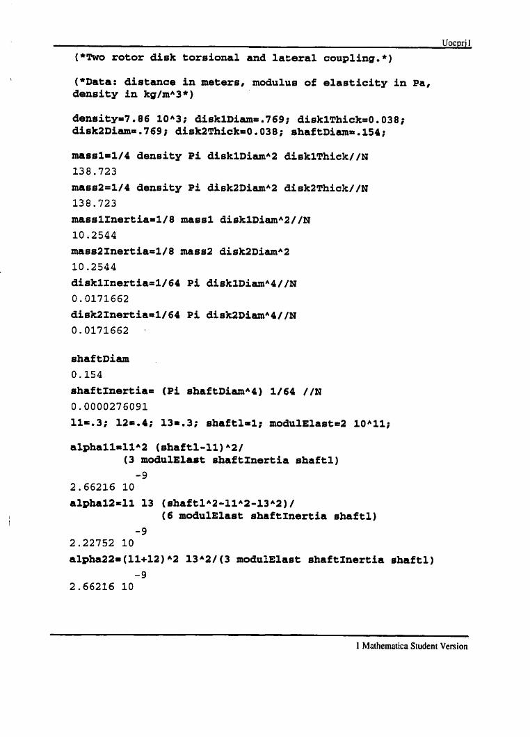
Uocpri 1
('Two rotor disk torsional and lateral coupling.*)
(*Data: distance in meters, modulue of elasticity in Pa, density in kg/mA3*)
massl=l/4 density Pi disklDiamA2 disklThick//~
138.723
mass2=1/4 density Pi disk2DiarnA2 disk2Thick//N
138.723
masslInertia=l/8 mass1 disklDiamA2//N
10.2544
mass21nertia=l/8 mass2 di8k2DiamA2
10.2544
disklInertia=l/64 Pi disklDirunA4//~
0.0171662
disk2lnertia=1/64 Pi disk2DiamA4//~
0.0171662
shaf tDiaxn
0.154
shaftInertia6 (Pi shaftDiamA4) 1/64 //N
0.0000276091
1 . 3 ; 12r.4; 131.3; shaftlrl; modulElast=Z 10A1l;
alphallrllA2 (~haft1-11)~2/ (3 moduSElast shaftznertia shaftl)
-9 2.66216 10
alphal2=11 13 (ahaftlA2-11A2-13A2)/ (6 modulElast shaftznertia shaftl)
shaftInertia shaftl)
1 Mathematics Student Version

kllastifMatrix[ [l, lJ J
2 Mnthematica Student Version

Page 123
Appendix C2
Program for calculating the natural frequencies of the two-disk rotor system.

((138.723, 0), (0, 138.723))
I Mothematica Student Version

Page 125
Appendix D
Rotor dynamic analysis of the experimental rotor model. Dimensional data of the shaft
as given in figure 5.5 on page 70 was used for this model. Advanced Rotating Machinery
Dynamic program of Rotor Bearing Technology and Software Inc. was used to compute
the damped natural frequencies of the model.

Page 116 **+ ROTOR BEARING TECHNOLOGY & SOFTWARE, INC. *** Page # STABILITY AND NATURAL FREQUENCY ANALYSIS PROGRAM FOR
AXISYMETRIC ROTATING SHAFTS *** ROSTAB *** [V4.OG1]
UOC project two ro to r bingham pump
THE ANALYSIS PERFORMED FOR THE FOLLOWING ROTOR SYSTEM CONFIGURATION >>>>>>>>>>>>>
NUMBER OF * STATIONS * THE SHAFT IS MODELED BY - - - - - - - > 21 NUMBER OF * SHAFT * ELEMENTS IN THE ROTOR SYSTEM - - > 20 NUMBER OF * DISCS * IN THE ROTOR SYSTEM - - - - - - - - - - - > 2 NUMBER OF * BEARINGS * IN THE ROTOR SYSTEM - - - - - - - - - - - > 2 NUMBER OF * MATERIALS* THE SHAF'TING IS COMPOSED OF - - - > 1 NUMBER OF * MODES * (Mode Shapes) TO BE PLOTTED - - - > 6
* GRAVITY * - - - - ( I~c~/sEc^~) - - - - - - - - - - - > .386403+03
Units of measures used for this problem are - - - - - - - - - - > [ US (English) 3
>>> MATERIAL DATA ccc
MATERIAL MODULUS OF SHEAR DENSITY MATERIAL
i NUMBER ELASTICITY MODULUS DAMPING # (LB/IN*~) (LB/IN^~) (LB/IN^~)
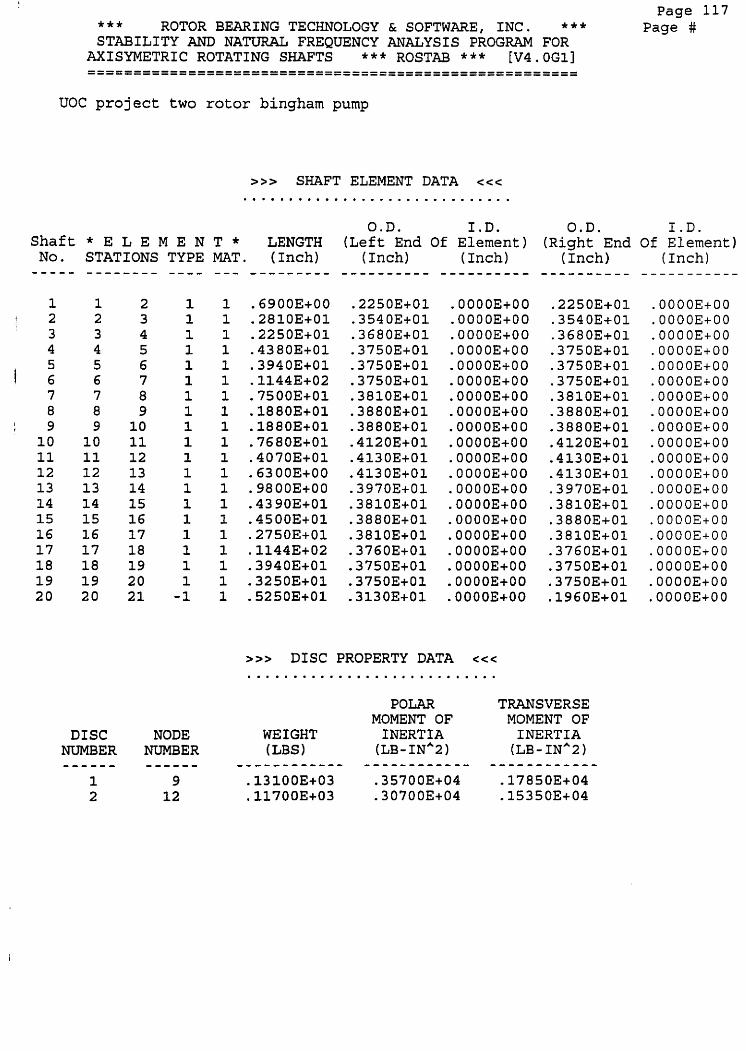
*** ROTOR BEARING TECHNOLOGY & SOFTWARE, INC. *** STABILITY AND NATURAL FREQUENCY ANALYSIS PROGRAM FOR
AXISYMETRIC ROTATING SHAFTS *** ROSTAB *** [V4.OG1]
UOC project two rotor bingham pump
Shaft * E L E M E N TYPE - - - -
1 1 1 1 1 1 1 1 1 1 1 1 1 1 1 1 I 1 1 -1
D I S C NODE NUMBER NUMBER
>>> SHAFT ELEMENT DATA <<c e . . . . . . . . . . . . . . . . . . . . . . . . . . . . .
O.D. I . D . (Left End Of Element)
>>> DISC PROPERTY DATA c c c
O.D. (Right End
( Inch)
POLAR TRANSVERSE MOMENT OF MOMENT OF
WEIGHT INERTIA INERTIA (LBS) ( L B - 1 ~ ~ 2 ) ( L B - 1 ~ ~ 2 )
----c------- - - - - - - - - - - - - - w e - - - - - - - - -
.13100E+03 .357003+04 .17850E+04
.11700E+03 .30700E+04 .153503+04
Page 117 Page #
I.D. Of Element)
( Inch)

UOC project two rotor bingham pump
THE STABILITY ANALYSIS PERFORMED WAS FOR SHAFT OPERATING SPEED OF - - - - - - - - - - - - - - - > 3600.0000 (RPM)
WITH BEARING & HOUSING STIFFNESS AND DAMPING MATRICES . . . . . . . . . . . . . . . . . . . . . . . . . . . . . . . . . . . . . . . . . . . . . . . . . . . .* a * . .
BEARING NUMBER ( 1 ) ; AT Node/~tation NUMBER ( 5 )
BEARING STIFFNESS MATRIX Size Specified = 2 [ Units are in LB/IN ]
BEARING DAMPING MATRIX : - [ Units are in LB-SEC/IN I
BEARING NUMBER ( 2 ) ; AT Node/Station NUMBER ( 19 )
BEARING STIFFNESS MATRIX Size Specified = 2 [ Units are in LB/IN ]
BEARING DAMPING MATRIX : - [ Units are in LB-SEC/IN ]
Page 118 Page #

Page 119 **+ ROTOR BEARING TECHNOLOGY & SOFTWARE, INC. +*+ Page # STABILITY AND NATURAL FREQUENCY ANALYSIS PROGRAM FOR
I AXISYMETRIC ROTATING SHAFTS *** ROSTAB *** [V4.OG1]
I UOC project two rotor bingham pump
4
>>> Analysis Performed With The Following Externally Applied Loads c c c . . . . . . . . . . . . . . . . . . . . . . . . . . . . . . . . . . . . . . . . . . . . . . . . . . . . * .* . . . . . . . * . . . . . . . . . +Y Number of Concentrated Nodal
Force & Moment Components - - - - - - - - - - - - - - - > 0 Gravity Loading Factor in X Direction - - - > . O O O
+ - - - - - > +X Gravity Loading Factor in Y Direction - - - > -1,000 / Gravity Constant (1n/secA2) - - - - - - - - - - - - - > .386403+03
+z /
>>> COMPUTED DEFLECTIONS (Displ. & Rot.) at EACH SHAFT STATION ccc [ * Calculations Consider Housing Stiffness Not Bearings * ]

Page 120 +** ROTOR BEARING TECHNOLOGY & SOFTWARE, I N C . *** Page # STABILITY AND NATURAL FREQUENCY ANALYSIS PROGRAM FOR
AXISYMETRXC ROTATING SHAFTS *** ROSTAB * * * [V4.OG1]
UOC project two r o t o r bingham pump
> > COMPUTED ROTOR PARAMETERS <c< ....... L . . . . . . . . . . . . . . . . . . . . . . . . . . .
Shaft Station
#
Axial Locat i on
( Inch) - - - - - - - - - - .00000E+00 .69000E+00 .35000E+01 .575003+01 .10130E+02 .14070E+02 .255103+02 .330103+02 .348903+02 .367703+02 .44450E+02 .46520E+O2 .491503+02 .501303+02 .5452OE+O2 .590203+02 .617703+02 .732103+02 .77150E+02 .804OOE+O2 .856503+02
Shaft Weight (lbs) - - - - - - - - - - - -
.3882OE+OO
.430163+01
.729973+01
.102313+02
.13003E+02
.240363+02
.299783+02
.15245E+02
.629073+01
.176333+02
.222033+02
.890933+01
.291083+01
.87986E+01
.146113+02
.11965E+02 .
.224113+02
.241323+02
.112373+02
.95039E+01
.326653+01
Shaft Moment of I n e r t i a (lb-inA2)
Disc Bear ing Weight (lbs) Station - - - - - - - - - - - - - - - - - - - - -
.00000E+00
.00000E+00
.00000E+00
.00000E+00
.00000E+00 Yes
.00000E+00
.00000E+00
.00000E+00
.13100E+03
.00000E+00
.00000E+00
.11700E+03
.00000E+00
.00000E+00
.00000E+00
.00000E+00
.00000E+00
.00000E+00
.00000E+00 Yes
.00000E+00
.00000E+00
Total Shaft Weight (LBS) - - - - - - - - - - - - - - - > 268.35280 Total Disc Weight (LBS) - - - - - - - - - - - - - - - > 248.00000 OVER ALL Rotor Weight (LBS) - - - - - - - - - - - - > 516.35280 Total Shaft Length (Inch) - - - - - - - - - - - - - - > 85.65000 C. G. Location from S t a t i o n 1 (Inch) - - - > 41.65440
>>> Computed Bearing REACTIONS ccc .. .....................*.......... Bearing Station Force (lbs) Force (lbs) Resultant Angle (Deg.) Number. Number, X-Direction Y-Direction (lbs) From +X Axis
1 - - - - - - - ------c - - - - - - - - - - - - - - - - - - - - - - - - - - - - - - - - - - - - ----_-. .----- 1 5 .00000E+00 .273523+03 .273523+03 .90000E+02 2 19 .00000E+00 .242893+03 .242893+03 .90000E+02

t Page 121
**+ ROTOR BEARING TECHNOLOGY & SOFTWARE, INC. *** Page # STABILITY AND NATURAL FREQUENCY ANALYSIS PROGRAM FOR
I AXISYMETRIC ROTATING SHAFTS *** ROSTAB *** [V4.OGlI I
t UOC project two rotor bingham pump !
ELEMENT FORCE-X FORCE -Y MOMENT-X MOMENT-Y FIBER-STR. SHEAR-STR. # Node (Shear) (Shear) (IN-LB) (IN-LB) Max. (KSI) Max. ( K S I )

Page 122

I Page 123
+++ ROTOR BEARING TECHNOLOGY & SOFTWARE, INC. **+ Page # STABILITY AND NATURAL FREQUENCY ANALYSIS PROGRAM FOR
! AXISYMETRIC ROTATING SHAFTS +** ROSTAB *** [V4.OG1]
t UOC project two r o t o r bingham pump
>>> STABILITY ANALYSIS <<< . . . . . . . . . . . . . . . . . . . . . . . . . . . . . . . . . . ..... -...............*......t.
Number Logarithmic
Decrement * F R E Q U E N C Y *

I I Page 124
83 -.169013+02 .92084E-01 .14654E-01 .183543+03 .11012E+05 85 - . 156223+02 .90309E-01 -143723-01 .17298E+03 .10379E+05
I 87 -.427893+00 .11035E-01 -175633-02 .38775E+02 .23265E+04 89 -.836633+01 .21641E+00 .34422E-01 .38659E+02 .23196E+04 91 -.15308E+03 .00000E+00 .00000E+00 .00000E+00 .00000E+00 92 -.147133+03 .00000E+00 .00000E+00 .00000E+00 .00000E+00
i

COUCENIRATED MASS CONCEHTRATED POLAR M)rrENT OF I N E R T I A COMCEMTRATED TRMSVERSE W K N T OF i M E R t l A
CODE r 60306 1 622
?OTOR UASS = 2.872E+02ko ?OfOR POLAR MACC HnMCMT r 3 . a n c r ~ n n ~ ,-9
Dimensional Details of the Pump Rotor
LATERAL ROTOR MODEL SCALE I rn 6.6 DATE@ 06.03. 96 t
C 1 ~ 7 2 5 Pump T y p e 1 2 ~ 1 2 ~ 1 5 . 5 MSD-D 2 S t g *

Page

Page 127

hode 3 of 6 183793+85 CPM
-814 R
length
Plot 5.7: Second Bending Mode of the Pump Rotor
At 172.92 Hz,


