

Thermostatic expansion valves
TUB and TUC series
Technical brochure
MAKING MODERN LIVING POSSIBLE
2 DKRCC.PD.AG0.B2.22/ 520H2959 © Danfoss A/S (RA-MC / mr), 03 - 2009
Technical brochure Thermostatic expansion valves, TUB and TUC series
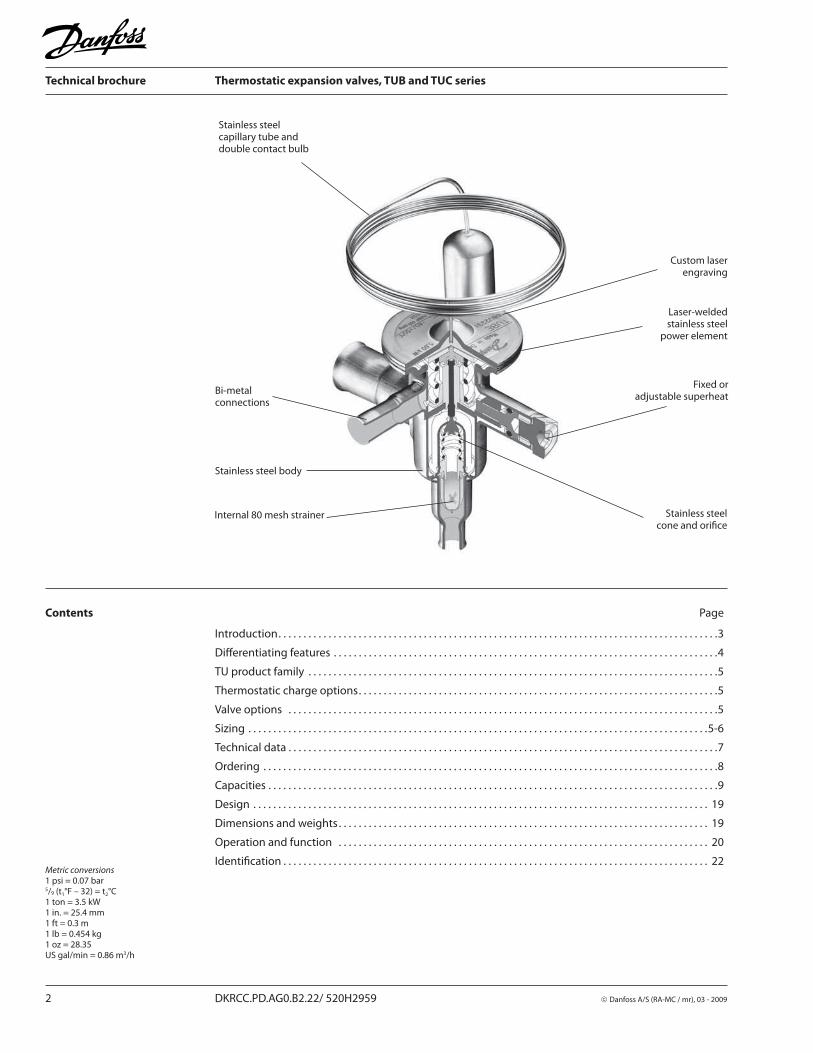
Stainless steelcapillary tube anddouble contact bulb
Custom laserengraving
Laser-weldedstainless steel
power element
Fixed oradjustable su per heat
Stainless steel cone and orifi ce
Stainless steel body
Internal 80 mesh strainer
Bi-metalconnections
Metric conversions1 psi = 0.07 bar5/9 (t1°F – 32) = t2°C1 ton = 3.5 kW1 in. = 25.4 mm1 ft = 0.3 m1 lb = 0.454 kg1 oz = 28.35US gal/min = 0.86 m3/h
Contents Page
Introduction. . . . . . . . . . . . . . . . . . . . . . . . . . . . . . . . . . . . . . . . . . . . . . . . . . . . . . . . . . . . . . . . . . . . . . . . . . . . . . . . . . . . . . . .3
Diff erentiating features . . . . . . . . . . . . . . . . . . . . . . . . . . . . . . . . . . . . . . . . . . . . . . . . . . . . . . . . . . . . . . . . . . . . . . . . . . . . .4
TU product family . . . . . . . . . . . . . . . . . . . . . . . . . . . . . . . . . . . . . . . . . . . . . . . . . . . . . . . . . . . . . . . . . . . . . . . . . . . . . . . . . .5
Thermostatic charge options. . . . . . . . . . . . . . . . . . . . . . . . . . . . . . . . . . . . . . . . . . . . . . . . . . . . . . . . . . . . . . . . . . . . . . . .5
Valve options . . . . . . . . . . . . . . . . . . . . . . . . . . . . . . . . . . . . . . . . . . . . . . . . . . . . . . . . . . . . . . . . . . . . . . . . . . . . . . . . . . . . . .5
Sizing . . . . . . . . . . . . . . . . . . . . . . . . . . . . . . . . . . . . . . . . . . . . . . . . . . . . . . . . . . . . . . . . . . . . . . . . . . . . . . . . . . . . . . . . . . . .5-6
Technical data . . . . . . . . . . . . . . . . . . . . . . . . . . . . . . . . . . . . . . . . . . . . . . . . . . . . . . . . . . . . . . . . . . . . . . . . . . . . . . . . . . . . . .7
Ordering . . . . . . . . . . . . . . . . . . . . . . . . . . . . . . . . . . . . . . . . . . . . . . . . . . . . . . . . . . . . . . . . . . . . . . . . . . . . . . . . . . . . . . . . . . .8
Capacities . . . . . . . . . . . . . . . . . . . . . . . . . . . . . . . . . . . . . . . . . . . . . . . . . . . . . . . . . . . . . . . . . . . . . . . . . . . . . . . . . . . . . . . . . .9
Design . . . . . . . . . . . . . . . . . . . . . . . . . . . . . . . . . . . . . . . . . . . . . . . . . . . . . . . . . . . . . . . . . . . . . . . . . . . . . . . . . . . . . . . . . . . 19
Dimensions and weights . . . . . . . . . . . . . . . . . . . . . . . . . . . . . . . . . . . . . . . . . . . . . . . . . . . . . . . . . . . . . . . . . . . . . . . . . . 19
Operation and function . . . . . . . . . . . . . . . . . . . . . . . . . . . . . . . . . . . . . . . . . . . . . . . . . . . . . . . . . . . . . . . . . . . . . . . . . . 20
Identifi cation . . . . . . . . . . . . . . . . . . . . . . . . . . . . . . . . . . . . . . . . . . . . . . . . . . . . . . . . . . . . . . . . . . . . . . . . . . . . . . . . . . . . . 22

© Danfoss A/S (RA-MC / mr), 03 - 2009 DKRCC.PD.AG0.B2.22/ 520H2959 3
Technical brochure Thermostatic expansion valves, TUB and TUC series
Introduction
The TU series of thermostatic expansion valves is specifi cally developed for soldering into hermetic refrigeration systems. TU valves are off ered in rated capacities up to 4.5 TR (R22) and can be used in a wide range of applications:
Conventional refrigeration systems
Heat pump systems
Air conditioning systems
Specialty refrigeration appliances
Liquid chillers
Ice Machines
Transport refrigeration
The TU is made of stainless steel and therefore is well-suited to refrigeration systems for aggressive environments and for the food industry.Danfoss also off ers a wide range of options that makes possible countless valve combinations.

© Danfoss A/S (RA-MC / mr), 03 - 2009 DKRCC.PD.AG0.B2.22/ 520H2959 4
Technical brochure Thermostatic expansion valves, TUB and TUC series
Diff erentiating features Stainless steel
High body strength
High corrosion resistance
Highly vibration-resistant, fl exible capillary tube
40% reserve capacity over nominal rating
Reduces pulldown time after defrost compared to conventional TXV's.
Bi-metal connections
Fast and easy soldering without the need for a wet cloth.
Precision Port designFour major features contributing to superior repeatable performance over an extended valve life:
Laser-welded power elementinsures diaphragm’s structural integrity and lengthens life.
Precision-machined push-rod and bushingavoid the need for a packing gland.
Free-fl oating push-rodis self-aligning and eliminates binding.
Precision-machined cone and orifi ceaccurately meter refrigerant under all operating conditions.
Stainless steel capillary tube
Tolerates more bending for easier installation and longer life.
Greater resistance to vibration during operation.
Stainless steel bulb
Self-aligning for fast and easy installation; secures with a single strap or Quick Clip.
More contact surface for better heat transfer.
Built-in Strainer
Angleway valve body:Unique 80 mesh strainer design capable of retaining more than twice the amount of dirt compared to that of a conventional design without restricting fl ow.
Straightway valve body:100 mesh strainer
Compact design
Small footprint and light weight for compact installation.
Laser engraving
Durable positive valve identifi cation; no labels to peel off over time.
Patented superheat adjustment device:
Adjust with 5/32” Allen wrench.
Versions with optional self-cleaning bleed port available
Bi-fl ow operation
Optional Quick Clip bulb fastener
For fast and easy installation.
Metric conversions1 psi = 0.07 bar5/9 (t1°F – 32) = t2°C1 ton = 3.5 kW1 in. = 25.4 mm1 ft = 0.3 m1 lb = 0.454 kg1 oz = 28.35US gal/min = 0.86 m3/h

5 DKRCC.PD.AG0.B2.22/ 520H2959 © Danfoss A/S (RA-MC / mr), 03 - 2009
Technical brochure Thermostatic expansion valves, TUB and TUC series
TU product family The TU family includes three valve types:TUA, TUB, and TUC.Standard confi gurations are as follows:
TUA, TUAE1)
Internal (TUA) or external (TUAE) equalization
Replaceable orifi ce and strainer
Adjustable superheat
Straightway body
TUB, TUBE
Internal (TUB) or external(TUBE) equalization
Fixed orifi ce and strainer
Adjustable superheat
Angleway body(straightway optional)
TUC, TUCE
Internal (TUC) or external(TUCE) equalization
Fixed orifi ce and strainer
Fixed superheat
Straightway or angleway body
Danfoss off ers the following standard range thermostatic charge:Range N: −40 to +50°F
Thermostatic charge options In addition to the standard range, TU is also available with the following range options:Range N: −40 to +50°F MOP∼ +60°FRange NM: −40 to +25°F MOP∼ +32°FRange B 1) −75 to −15°FRange B 1) −75 to −15°F MOP∼ −4°F1) TU valves for range B are not supplied for R134a.
Valve options
For information on all custom valve options including the TUC series, please contact Danfoss.
Sizing For optimum performance, it is important to select a TU valve according to system conditions and application. Selecting an incorrect valve will result in operational diffi culties or poor system performance.The following procedure will help you select the correct valve for your needs.
Example:Refrigerant = R22
Evaporator capacity:Q
e = 13,000 Btu (1.08 TR)
Evaporating temperature:t
e = +40°F (equals p
e = 70 psig)
Condensing temperature:t
c = +100°F (equals p
c = 195 psig)
Liquid refrigerant temperature:t
l = +80°F
Step 1 The pressures pc and p
e can be found by using
the design condensing and evaporating tempera-tures at the saturated vapor point, then using a pressure temperature chart or a Danfoss refrigerant slide to convert the temperatures to pressures.In this example, the pressure drop across the valve will be:Δp = p
c − p
e = 195 − 70 = 125 psi.
Determine the pressure drop across the valveThe pressure drop, Δp, is calculated by the formula:Δp = p
c − p
e − pdw
wherep
c = condensing pressure
pe = evaporating pressure, and
pdw = the sum of other pressure drops in the liquid line, evaporator, and distributor.
TUB, TUBE connections,inlet × outlet
Connection sizesInlet × outlet: 1/4 in. × 3/8 in. 1/4 in. × 1/2 in. 3/8 in. × 3/8 in. 3/8 in. × 1/2 in. 1/2 in. × 5/8 in.External equalization: 1/4 in.
15% bleed port (optional)
Capillary tube length2.6 ft. (5 ft. optional)
Static superheat settings3.5°F, 5.5°F, 7°F, 11°FStandard = 9°F, charge N, (R507 = 11°F)
Non-adjustable superheat (type TUC,TUCE)
1) For additional information, please see technical leafl et on TUA/TUAE.
Metric conversions1 psi = 0.07 bar5/9 (t
1°F – 32) = t
2°C
1 ton = 3.5 kW1 in. = 25.4 mm1 ft = 0.3 m
Orifi ce no.Angleway body
1/4 × 3/81/4 × 1/2
3/8 × 3/83/8 × 1/2
0 → 6
7 → 9
Standard Optional

© Danfoss A/S (RA-MC / mr), 03 - 2009 DKRCC.PD.AG0.B2.22/ 520H2959 6
Technical brochure Thermostatic expansion valves, TUB and TUC series
Determine required valve capacity.Use the design evaporator capacity, Q
e, to select
the required valve size at a given evaporating temperature. If necessary, correct the evaporator capacity for subcooling. Subcooled liquid refrigerant entering the evaporator increases evaporator capacity, so that a smaller valve may be required.
In this example, the subcooling is:Δt
sub = t
c − t
l = 100 − 80 = 20°F
From the subcooling correction factor table, on page 10, we fi nd the appropriate correction factor F
sc equals 0.94 for Δt
sub = 20°F. Now, determine
the required valve capacity by multiplying the evaporator capacity by the correction factor for subcooling.
Required valve capacityQ
e × F
sc = 1.08 × 0.94 = 1.02 TR
Sizing(continued)Step 2
Note that the expansion valve capacity must be equal to or slightly more than the corrected evaporator capacity.In this sizing example, orifi ce 5 will be suitable.
Use the calculated valve capacity to select the corresponding orifi ce size from the capacity table for R22 as indicated below.
Step 3
Capacities (TR)
Range N: –40 → +50°F. Δtsub
= 10°F, OS = 7°F
TypeOrifi ce
no.
Pressure drop across valve Δp psi
50 75 100 125 150 175 200 225
Evaporating temperature +40°F
0 0.14 0.16 0.18 0.19 0.20 0.20 0.20 0.20
1 0.21 0.24 0.26 0.27 0.28 0.29 0.29 0.30
2 0.28 0.33 0.36 0.38 0.40 0.41 0.42 0.43
3 0.39 0.45 0.50 0.53 0.56 0.57 0.58 0.59
4 0.59 0.68 0.75 0.80 0.83 0.86 0.88 0.88
5 0.78 0.91 0.99 1.06 1.11 1.15 1.17 1.19
6 1.18 1.37 1.50 1.60 1.67 1.73 1.77 1.80
7 1.57 1.82 2.00 2.13 2.23 2.30 2.35 2.40
The extended capacity tables can be found on pages 8 to17.
Select a thermostatic chargeDanfoss off ers a universal wide range thermostatic charge, Range N, suited for most applications in the normal temperature range.
The table on page 7 include standard range N valves only. Ranges NM and B are available for special low temperature applications.
Step 5 Determine if external equalization is required.
Note! External equalization is always required if a distributor is used or if there is an appreciable diff erence in pressure across the evaporator.
Finally, determine connection sizes, then fi nd the valve's code number from the table on page 7.
Step 4
Metric conversions1 psi = 0.07 bar5/9 (t
1°F – 32) = t
2°C
1 ton = 3.5 kW

7 DKRCC.PD.AG0.B2.22/ 520H2959 © Danfoss A/S (RA-MC / mr), 03 - 2009
Technical brochure Thermostatic expansion valves, TUB and TUC series
Technical data Maximum bulb temperature212°F
Maximum valve body temperature250°FShort-lived peak 300°F
Maximum working pressure (excl. R410A)MWP = 500 psig
Maximum test pressure (excl. R410A)p’ = 540 psig
Maximum working pressure, R410AMWP = 615 psig
Maximum test pressure, R410Ap’ = 680 psig
Capillary tube length2.6 or 5 ft.
Standard static superheat setting, Range N (R22, R134a, R404A, R407C, R410A) = 9°FRange N (R507) = 11°F Standard refrigerantsR22, R134a, R404A, R407C, R410A and R507.
TU valves are continually evaluated for use with newer refrigerants. For more information, please contact Danfoss.
Refrigerant
Range N
−40 to +50°F
Range NM
−40 to +25°F
Range B
−75 to −15°F
MOP point for evaporating temperature te and evaporating pressure p
e
te = 60°F t
e = 32°F t
e=−4°F
R22 pe = 100 psig p
e = 60 psig p
e = 20 psig
R134a pe = 55 psig p
e = 30 psig
R404A / R507 pe = 120 psig p
e = 75 psig p
e = 30 psig
R407C pe = 95 psig p
e = 50 psig p
e = 15 psig
R410A pe = 165 psig p
e = 100 psig p
e = 45 psig
MOP valvesTo avoid risk of charge migration when using MOP valves, the bulb temperature must always be lower than the thermostatic element temperature.
For code nos. on valves having NM and B range charges and other MOP valves not listed in this leafl et, please contact Danfoss.
MOP points
Metric conversions1 psi = 0.07 bar5/9 (t
1°F – 32) = t
2°C
1 ton = 3.5 kW1 in. = 25.4 mm1 ft = 0.3 m

© Danfoss A/S (RA-MC / mr), 03 - 2009 DKRCC.PD.AG0.B2.22/ 520H2959 8
Technical brochure Thermostatic expansion valves, TUB and TUC series
Valve
type
Connection
Solder ODF
inlet ×
outlet
in.
Press.
equal.
Orifi ce
no.3)
R22 R134a R404A/R507 R407C R410A
Range N
–40 to +50°F
Range N
–40 to +50°F
Range N
–40 to +50°F
Range N
–40 to +50°F
Range N
–40 to +50°F
Rated
capacity
TR22)
Code no.
Rated
capacity
TR22)
Code no.
Rated
capacity
TR22)
Code no.
Rated
capacity
TR22)
Code no.
Rated
capacity
TR22)
Code no.
0 0.13 068U2660
TUB
1/4 × 1/2
Int.
1 0.25 068U2057 0.19 068U2027 0.19 068U2094 0.40 068U1958
2 0.36 068U2058 0.28 068U2028 0.28 068U2095 0.60 068U1959
3 0.50 068U2059 0.39 068U2029 0.39 068U2096 0.80 068U1960
4 0.75 068U2060 0.59 068U2030 0.60 068U2097 1.30 068U1961
5 1.00 068U2061 0.78 068U2031 0.79 068U2098 1.70 068U1962
6 1.50 068U2062 1.20 068U2032 1.20 068U2099 2.50 068U1963
3/8 × 1/2
1 0.25 068U2157
2 0.36 068U2179
3 0.50 068U2180
4 0.75 068U2183
5 1.00 068U2181
6 1.50 068U2182
7 2.00 068U2063
8 3.00 068U2064
TUBE
1/4 × 1/2
Ext.1/4 in.
solder
ODF
1 0.19 068U2103
2 0.28 068U2104
3 0.39 068U2020 0.39 068U2105
4 0.75 068U2070 0.59 068U2021 0.60 068U2106
5 1.00 068U2071 0.78 068U2022 0.79 068U2107 1.10 068U1935
6 1.50 068U2072 1.20 068U2023 1.20 068U2108 1.60 068U1936
3/8 × 1/2
1 0.25 068U2159
2 0.36 068U2160
3 0.50 068U2161
4 0.75 068U2162
5 1.00 068U2163
6 1.50 068U2164
7 2.00 068U2073 1.60 068U2024 1.60 068U2109 2.10 068U1937 3.40 068U1973
8 3.00 068U2074 2.30 068U2025 2.40 068U2110 3.20 068U1938 5.00 068U1974
9 4.50 068U2075 3.50 068U2026 3.50 068U2111 4.80 068U1939 7.50 068U1975
TUB seriesOrdering
Angleway valve body with 2.6 ft. cap. tube and bulb strap1)Range N: −40 to +50°F (without MOP)
1) The TUB series is also available with 5 ft. cap. tube. Please contact Danfoss for further information.2) According to ARI 750 Rated capacities for range N are based on: Liquid temperature ahead of expansion valve t
l = 100°F
Evaporating temperature te = 40°F
Pressure drop across valve Δp = 60 psi for R134a Pressure drop across valve Δp = 100 psi for R22, R404A, R407C and R507 Pressure drop across valve Δp = 160 psi for R410A3) All TUB and TUBE valves with orifi ce 0 and 9 cannot be used for bi-fl ow operation.
Metric conversions1 psi = 0.07 bar5/9 (t
1°F – 32) = t
2°C
1 ton = 3.5 kW1 in. = 25.4 mm

9 DKRCC.PD.AG0.B2.22/ 520H2959 © Danfoss A/S (RA-MC / mr), 03 - 2009
Technical brochure Thermostatic expansion valves, TUB and TUC series
Capacities (TR)
Range N: –40 to +50°F. Δtsub
= 10°F, OS = 7°F
Correction factor forsubcooling Δt
sub
Refrigerant 0°F 10°F 20°F 30°F 40°F 50°F 60°F 70°F 80°F 90°F
R22 1.08 1.00 0.94 0.89 0.85 0.81 0.78 0.74 0.71 0.68
Metric conversions1 psi = 0.07 bar5/9 (t
1°F – 32) = t
2°C
1 ton = 3.5 kW
When subcooling Δtsub
ahead of the expansion valve
is other than 10°F, adjust the evaporator
capacity by multiplying by the appropriate correction factor found in the following table.
TypeOrifi ce
no.
Pressure drop across valve Δp psiType
Orifi ce
no.
Pressure drop across valve Δp psi
50 75 100 125 150 175 200 225 50 75 100 125 150 175 200 225
Evaporating temperature +50°F Evaporating temperature 0°F
TU
0 0.15 0.17 0.18 0.19 0.20 0.20 0.21 0.21
TU
0 0.12 0.13 0.14 0.15 0.15 0.16 0.16 0.16
1 0.22 0.25 0.27 0.29 0.30 0.30 0.31 0.31 1 0.14 0.16 0.18 0.19 0.20 0.20 0.21 0.21
2 0.31 0.36 0.40 0.43 0.44 0.46 0.47 0.48 2 0.17 0.20 0.22 0.23 0.24 0.26 0.25 0.26
3 0.43 0.50 0.55 0.59 0.61 0.63 0.65 0.66 3 0.24 0.28 0.30 0.32 0.34 0.35 0.35 0.36
4 0.65 0.76 0.83 0.89 0.93 0.96 0.98 1.00 4 0.36 0.41 0.45 0.48 0.50 0.51 0.52 0.53
5 0.87 1.01 1.11 1.18 1.23 1.27 1.30 1.32 5 0.48 0.55 0.60 0.64 0.66 0.68 0.70 0.70
6 1.30 1.51 1.67 1.78 1.86 1.93 1.96 2.00 6 0.72 0.83 0.90 0.95 0.99 1.02 1.04 1.05
7 1.73 2.01 2.22 2.36 2.48 2.56 2.61 2.66 7 0.96 1.10 1.20 1.28 1.33 1.37 1.39 1.41
8 2.58 3.00 3.31 3.53 3.69 3.81 3.90 3.97 8 1.45 1.67 1.81 1.92 2.00 2.06 2.10 2.12
9 3.87 4.52 4.97 5.29 5.53 5.71 5.84 5.93 9 2.14 2.46 2.68 2.83 2.95 3.03 3.09 3.12
Evaporating temperature +40°F Evaporating temperature −20°F
TU
0 0.14 0.16 0.18 0.19 0.20 0.20 0.20 0.20
TU
0 0.10 0.11 0.12 0.12 0.13 0.13 0.13 0.13
1 0.21 0.24 0.26 0.27 0.28 0.29 0.29 0.30 1 0.11 0.13 0.14 0.14 0.15 0.15 0.16 0.16
2 0.28 0.33 0.36 0.38 0.40 0.41 0.42 0.43 2 0.13 0.15 0.16 0.17 0.18 0.18 0.18 0.19
3 0.39 0.45 0.50 0.53 0.56 0.57 0.58 0.59 3 0.18 0.21 0.23 0.24 0.25 0.25 0.26 0.26
4 0.59 0.68 0.75 0.80 0.83 0.86 0.88 0.88 4 0.27 0.31 0.33 0.35 0.36 0.37 0.38 0.38
5 0.78 0.91 0.99 1.06 1.11 1.15 1.17 1.19 5 0.36 0.41 0.44 0.47 0.49 0.50 0.51 0.51
6 1.18 1.37 1.50 1.60 1.67 1.73 1.77 1.80 6 0.53 0.61 0.66 0.70 0.72 0.74 0.76 0.76
7 1.57 1.82 2.00 2.13 2.23 2.30 2.35 2.40 7 0.71 0.81 0.88 0.93 0.97 1.00 1.01 1.02
8 2.34 2.72 2.99 3.19 3.33 3.44 3.51 3.57 8 1.08 1.23 1.34 1.41 1.46 1.50 1.53 1.55
9 3.52 4.06 4.46 4.76 4.97 5.13 5.25 5.37 9 1.58 1.80 1.96 2.07 2.14 2.20 2.25 2.26
Evaporating temperature +20°F Evaporating temperature −40°F
TU
0 0.13 0.15 0.16 0.17 0.17 0.18 0.18 0.18
TU
0 0.07 0.08 0.09 0.10 0.10 0.10 0.10 0.10
1 0.18 0.20 0.22 0.23 0.24 0.25 0.25 0.26 1 0.08 0.09 0.10 0.10 0.11 0.11 0.11 0.11
2 0.23 0.26 0.28 0.30 0.32 0.33 0.33 0.34 2 0.09 0.11 0.11 0.12 0.12 0.13 0.13 0.13
3 0.31 0.36 0.40 0.42 0.44 0.45 0.46 0.47 3 0.13 0.15 0.16 0.17 0.17 0.18 0.18 0.18
4 0.47 0.54 0.59 0.63 0.66 0.67 0.69 0.70 4 0.19 0.22 0.23 0.25 0.26 0.26 0.27 0.27
5 0.62 0.72 0.79 0.84 0.87 0.90 0.92 0.93 5 0.26 0.29 0.31 0.33 0.34 0.35 0.36 0.36
6 0.93 1.08 1.18 1.26 1.31 1.35 1.38 1.40 6 0.38 0.43 0.47 0.49 0.51 0.52 0.53 0.53
7 1.25 1.44 1.58 1.68 1.75 1.80 1.84 1.87 7 0.51 0.58 0.63 0.66 0.68 0.70 0.71 0.72
8 1.88 2.17 2.37 2.52 2.63 2.71 2.77 2.80 8 0.77 0.88 0.95 1.00 1.04 1.06 1.07 1.08
9 2.97 3.22 3.51 3.74 3.90 4.02 4.10 4.16 9 1.12 1.28 1.38 1.45 1.50 1.54 1.56 1.58
R22

© Danfoss A/S (RA-MC / mr), 03 - 2009 DKRCC.PD.AG0.B2.22/ 520H2959 10
Technical brochure Thermostatic expansion valves, TUB and TUC series
Capacities (TR)(continued)Range B: –75 to –10°F. ∆t
sub = 10°F, OS = 7°F
Correction factor for subcooling Δt
sub
Refrigerant 0°F 10°F 20°F 30°F 40°F 50°F 60°F 70°F 80°F 90°F
R22 1.08 1.00 0.94 0.89 0.85 0.81 0.78 0.74 0.71 0.68
Metric conversions1 psi = 0.07 bar5/9 (t
1°F – 32) = t
2°C
1 ton = 3.5 kW
When subcooling Δtsub
ahead of the expansion valve
is other than 10°F, adjust the evaporator
capacity by multiplying by the appropriate correction factor found in the following table.
TypeOrifi ce
no.
Pressure drop across valve Δp psiType
Orifi ce
no.
Pressure drop across valve Δp psi
50 75 100 125 150 175 200 225 50 75 100 125 150 175 200 225
Evaporating temperature – 15°F Evaporating temperature –60°F
TU
0 0.12 0.14 0.15 0.16 0.16 0.16 0.17 0.17
TU
0 0.07 0.07 0.08 0.08 0.09 0.09 0.09 0.09
1 0.16 0.18 0.20 0.21 0.22 0.22 0.23 0.23 1 0.07 0.08 0.08 0.09 0.09 0.09 0.09 0.10
2 0.20 0.23 0.25 0.27 0.27 0.28 0.29 0.29 2 0.08 0.09 0.10 0.10 0.11 0.11 0.11 0.11
3 0.28 0.32 0.35 0.37 0.38 0.39 0.40 0.40 3 0.11 0.13 0.14 0.14 0.15 0.15 0.15 0.16
4 0.42 0.48 0.52 0.54 0.57 0.58 0.59 0.60 4 0.16 0.19 0.20 0.21 0.22 0.22 0.22 0.23
5 0.56 0.64 0.69 0.73 0.76 0.77 0.79 0.80 5 0.22 0.25 0.27 0.28 0.29 0.30 0.30 0.30
6 0.83 0.95 1.03 1.09 1.13 1.16 1.19 1.20 6 0.33 0.37 0.40 0.42 0.43 0.44 0.45 0.45
7 1.11 1.27 1.38 1.46 1.52 1.56 1.58 1.60 7 0.44 0.50 0.53 0.56 0.58 0.59 0.60 0.61
8 1.68 1.91 2.08 2.19 2.28 2.34 2.38 2.40 8 0.66 0.75 0.81 0.85 0.88 0.90 0.91 0.92
9 2.48 2.83 3.07 3.24 3.40 3.45 3.51 3.55 9 0.97 1.09 1.17 1.23 1.27 1.30 1.32 1.33
Evaporating temperature –30°F Evaporating temperature –75°F
TU
0 0.11 0.12 0.13 0.13 0.14 0.14 0.14 0.14
TU
0 0.05 0.05 0.06 0.06 0.06 0.06 0.06 0.06
1 0.13 0.14 0.16 0.16 0.17 0.17 0.18 0.18 1 0.05 0.06 0.06 0.06 0.06 0.07 0.07 0.07
2 0.15 0.17 0.19 0.20 0.20 0.21 0.21 0.21 2 0.06 0.06 0.07 0.07 0.07 0.08 0.08 0.08
3 0.21 0.24 0.26 0.28 0.29 0.29 0.30 0.30 3 0.08 0.09 0.10 0.10 0.10 0.11 0.11 0.11
4 0.31 0.36 0.38 0.40 0.42 0.43 0.44 0.44 4 0.12 0.13 0.14 0.15 0.15 0.16 0.16 0.16
5 0.42 0.48 0.51 0.54 0.56 0.58 0.59 0.59 5 0.16 0.18 0.19 0.20 0.20 0.21 0.21 0.21
6 0.62 0.71 0.77 0.81 0.84 0.86 0.87 0.88 6 0.23 0.26 0.28 0.29 0.30 0.31 0.31 0.32
7 0.83 0.95 1.03 1.08 1.12 1.15 1.17 1.18 7 0.31 0.35 0.38 0.39 0.41 0.42 0.42 0.42
8 1.26 1.43 1.55 1.63 1.69 1.74 1.76 1.78 8 0.47 0.53 0.57 0.60 0.62 0.63 0.64 0.64
9 1.85 2.10 2.27 2.40 2.48 2.54 2.58 2.61 9 0.68 0.77 0.83 0.86 0.89 0.91 0.92 0.93
Evaporating temperature –45°F
TU
0 0.09 0.10 0.11 0.11 0.11 0.12 0.12 0.12
1 0.09 0.11 0.12 0.12 0.13 0.13 0.13 0.13
2 0.11 0.13 0.14 0.14 0.15 0.15 0.15 0.16
3 0.16 0.18 0.19 0.20 0.21 0.21 0.22 0.22
4 0.23 0.26 0.28 0.29 0.30 0.31 0.32 0.32
5 0.31 0.35 0.37 0.39 0.41 0.42 0.42 0.43
6 0.46 0.52 0.56 0.59 0.61 0.62 0.63 0.64
7 0.61 0.69 0.75 0.79 0.81 0.83 0.85 0.85
8 0.92 1.05 1.13 1.19 1.23 1.26 1.28 1.29
9 1.35 1.53 1.65 1.73 1.79 1.84 1.86 1.88
R22
11 DKRCC.PD.AG0.B2.22/ 520H2959 © Danfoss A/S (RA-MC / mr), 03 - 2009
Technical brochure Thermostatic expansion valves, TUB and TUC series
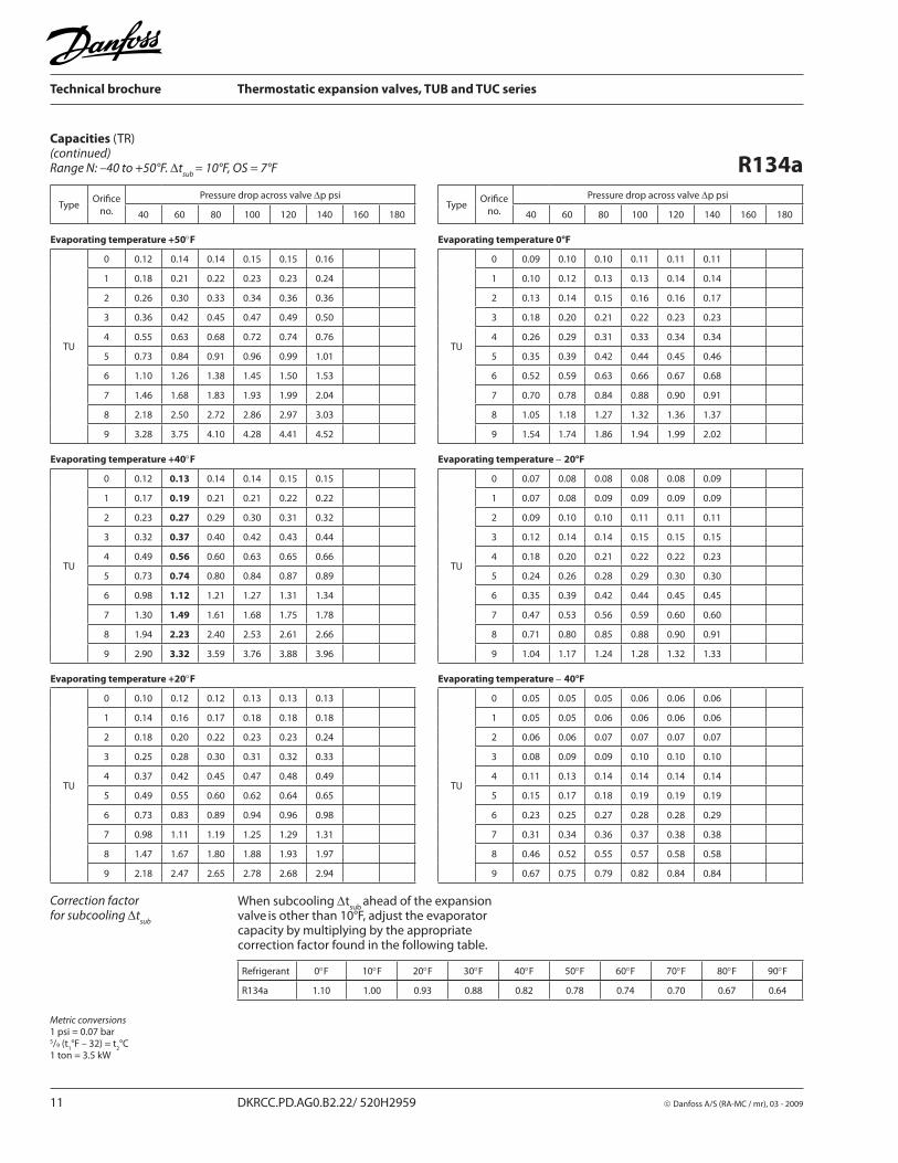
Capacities (TR)(continued)Range N: –40 to +50°F. Δt
sub = 10°F, OS = 7°F
Refrigerant 0°F 10°F 20°F 30°F 40°F 50°F 60°F 70°F 80°F 90°F
R134a 1.10 1.00 0.93 0.88 0.82 0.78 0.74 0.70 0.67 0.64
Correction factorfor subcooling Δt
sub
Metric conversions1 psi = 0.07 bar5/9 (t
1°F – 32) = t
2°C
1 ton = 3.5 kW
When subcooling Δtsub
ahead of the expansion valve
is other than 10°F, adjust the evaporator
capacity by multiplying by the appropriate correction factor found in the following table.
R134a
TypeOrifi ce
no.
Pressure drop across valve Δp psiType
Orifi ce
no.
Pressure drop across valve Δp psi
40 60 80 100 120 140 160 180 40 60 80 100 120 140 160 180
Evaporating temperature +50°F Evaporating temperature 0°F
TU
0 0.12 0.14 0.14 0.15 0.15 0.16
TU
0 0.09 0.10 0.10 0.11 0.11 0.11
1 0.18 0.21 0.22 0.23 0.23 0.24 1 0.10 0.12 0.13 0.13 0.14 0.14
2 0.26 0.30 0.33 0.34 0.36 0.36 2 0.13 0.14 0.15 0.16 0.16 0.17
3 0.36 0.42 0.45 0.47 0.49 0.50 3 0.18 0.20 0.21 0.22 0.23 0.23
4 0.55 0.63 0.68 0.72 0.74 0.76 4 0.26 0.29 0.31 0.33 0.34 0.34
5 0.73 0.84 0.91 0.96 0.99 1.01 5 0.35 0.39 0.42 0.44 0.45 0.46
6 1.10 1.26 1.38 1.45 1.50 1.53 6 0.52 0.59 0.63 0.66 0.67 0.68
7 1.46 1.68 1.83 1.93 1.99 2.04 7 0.70 0.78 0.84 0.88 0.90 0.91
8 2.18 2.50 2.72 2.86 2.97 3.03 8 1.05 1.18 1.27 1.32 1.36 1.37
9 3.28 3.75 4.10 4.28 4.41 4.52 9 1.54 1.74 1.86 1.94 1.99 2.02
Evaporating temperature +40°F Evaporating temperature − 20°F
TU
0 0.12 0.13 0.14 0.14 0.15 0.15
TU
0 0.07 0.08 0.08 0.08 0.08 0.09
1 0.17 0.19 0.21 0.21 0.22 0.22 1 0.07 0.08 0.09 0.09 0.09 0.09
2 0.23 0.27 0.29 0.30 0.31 0.32 2 0.09 0.10 0.10 0.11 0.11 0.11
3 0.32 0.37 0.40 0.42 0.43 0.44 3 0.12 0.14 0.14 0.15 0.15 0.15
4 0.49 0.56 0.60 0.63 0.65 0.66 4 0.18 0.20 0.21 0.22 0.22 0.23
5 0.73 0.74 0.80 0.84 0.87 0.89 5 0.24 0.26 0.28 0.29 0.30 0.30
6 0.98 1.12 1.21 1.27 1.31 1.34 6 0.35 0.39 0.42 0.44 0.45 0.45
7 1.30 1.49 1.61 1.68 1.75 1.78 7 0.47 0.53 0.56 0.59 0.60 0.60
8 1.94 2.23 2.40 2.53 2.61 2.66 8 0.71 0.80 0.85 0.88 0.90 0.91
9 2.90 3.32 3.59 3.76 3.88 3.96 9 1.04 1.17 1.24 1.28 1.32 1.33
Evaporating temperature +20°F Evaporating temperature − 40°F
TU
0 0.10 0.12 0.12 0.13 0.13 0.13
TU
0 0.05 0.05 0.05 0.06 0.06 0.06
1 0.14 0.16 0.17 0.18 0.18 0.18 1 0.05 0.05 0.06 0.06 0.06 0.06
2 0.18 0.20 0.22 0.23 0.23 0.24 2 0.06 0.06 0.07 0.07 0.07 0.07
3 0.25 0.28 0.30 0.31 0.32 0.33 3 0.08 0.09 0.09 0.10 0.10 0.10
4 0.37 0.42 0.45 0.47 0.48 0.49 4 0.11 0.13 0.14 0.14 0.14 0.14
5 0.49 0.55 0.60 0.62 0.64 0.65 5 0.15 0.17 0.18 0.19 0.19 0.19
6 0.73 0.83 0.89 0.94 0.96 0.98 6 0.23 0.25 0.27 0.28 0.28 0.29
7 0.98 1.11 1.19 1.25 1.29 1.31 7 0.31 0.34 0.36 0.37 0.38 0.38
8 1.47 1.67 1.80 1.88 1.93 1.97 8 0.46 0.52 0.55 0.57 0.58 0.58
9 2.18 2.47 2.65 2.78 2.68 2.94 9 0.67 0.75 0.79 0.82 0.84 0.84

© Danfoss A/S (RA-MC / mr), 03 - 2009 DKRCC.PD.AG0.B2.22/ 520H2959 12
Technical brochure Thermostatic expansion valves, TUB and TUC series
Capacities (TR)(continued)Range N: –40 to +50°F. Δt
sub = 10°F, OS = 7°F
Refrigerant 0°F 10°F 20°F 30°F 40°F 50°F 60°F 70°F 80°F 90°F
R404A 1.18 1.00 0.89 0.81 0.74 0.68 0.63 0.60 0.56 0.53
Correction factorfor subcooling ∆t
sub
Metric conversions1 psi = 0.07 bar5/9 (t
1°F – 32) = t
2°C
1 ton = 3.5 kW
When subcooling Δtsub
ahead of the expansion valve
is other than 10°F, adjust the evaporator
capacity by multiplying by the appropriate correction factor found in the following table.
R404A
TypeOrifi ce
no.
Pressure drop across valve ∆p psiType
Orifi ce
no.
Pressure drop across valve Δp psi
75 100 125 150 175 200 225 250 75 100 125 150 175 200 225 250
Evaporating temperature +50°F Evaporating temperature 0°F
TU
0 0.12 0.13 0.14 0.14 0.14 0.13 0.13 0.13
TU
0 0.10 0.11 0.11 0.11 0.11 0.11 0.11 0.10
1 0.19 0.20 0.21 0.21 0.21 0.20 0.20 0.19 1 0.13 0.14 0.14 0.15 0.15 0.15 0.14 0.14
2 0.28 0.30 0.31 0.32 0.32 0.32 0.31 0.30 2 0.16 0.17 0.18 0.18 0.18 0.18 0.18 0.17
3 0.38 0.41 0.43 0.44 0.44 0.44 0.43 0.42 3 0.23 0.24 0.25 0.25 0.25 0.25 0.25 0.24
4 0.59 0.63 0.65 0.67 0.67 0.67 0.65 0.64 4 0.34 0.36 0.37 0.37 0.37 0.37 0.36 0.35
5 0.78 0.83 0.87 0.89 0.89 0.88 0.88 0.85 5 0.45 0.48 0.49 0.50 0.50 0.49 0.48 0.47
6 1.17 1.26 1.31 1.34 1.35 1.34 1.32 1.28 6 0.67 0.72 0.74 0.75 0.75 0.74 0.73 0.71
7 1.56 1.68 1.74 1.78 1.78 1.78 1.75 1.70 7 0.90 0.96 0.99 1.00 1.00 0.99 0.97 0.94
8 2.32 2.49 2.60 2.65 3.66 2.64 2.60 2.53 8 1.36 1.44 1.49 1.51 1.51 1.48 1.46 1.42
9 3.49 3.74 3.90 4.00 3.99 3.95 3.89 3.79 9 2.00 2.13 2.20 2.23 2.22 2.20 2.15 2.09
Evaporating temperature +40°F Evaporating temperature −20°F
TU
0 0.12 0.13 0.13 0.13 0.13 0.13 0.13 0.13
TU
0 0.09 0.09 0.09 0.09 0.09 0.09 0.09 0.09
1 0.18 0.19 0.20 0.20 0.20 0.20 0.19 0.19 1 0.10 0.11 0.11 0.11 0.11 0.11 0.11 0.10
2 0.26 0.28 0.29 0.29 0.29 0.29 0.29 0.28 2 0.12 0.13 0.13 0.13 0.13 0.13 0.13 0.12
3 0.35 0.38 0.40 0.40 0.40 0.40 0.39 0.39 3 0.17 0.18 0.19 0.19 0.19 0.18 0.18 0.17
4 0.54 0.58 0.60 0.61 0.61 0.61 0.60 0.58 4 0.25 0.27 0.27 0.28 0.27 0.27 0.26 0.26
5 0.71 0.76 0.79 0.81 0.81 0.81 0.79 0.77 5 0.34 0.36 0.36 0.37 0.37 0.36 0.35 0.34
6 1.07 1.15 1.20 1.22 1.23 1.22 1.20 1.17 6 0.50 0.53 0.54 0.55 0.55 0.54 0.53 0.51
7 1.43 1.53 1.59 1.63 1.63 1.61 1.60 1.56 7 0.67 0.71 0.73 0.74 0.73 0.72 0.71 0.68
8 2.13 2.29 2.38 2.43 2.44 2.42 2.37 2.31 8 1.01 1.07 1.10 1.11 1.10 1.09 1.06 1.03
9 3.20 3.41 3.56 3.62 3.64 3.61 3.55 3.46 9 1.49 1.57 1.61 1.63 1.62 1.59 1.56 1.51
Evaporating temperature +20°F Evaporating temperature −40°F
TU
0 0.11 0.12 0.12 0.12 0.12 0.12 0.12 0.12
TU
0 0.07 0.07 0.07 0.07 0.07 0.07 0.07 0.07
1 0.16 0.17 0.18 0.18 0.18 0.17 0.17 0.17 1 0.07 0.08 0.08 0.08 0.08 0.08 0.08 0.07
2 0.21 0.22 0.23 0.24 0.23 0.23 0.23 0.22 2 0.09 0.09 0.09 0.09 0.09 0.09 0.09 0.09
3 0.29 0.31 0.32 0.33 0.33 0.32 0.32 0.31 3 0.12 0.13 0.13 0.13 0.13 0.13 0.13 0.12
4 0.44 0.46 0.48 0.49 0.49 0.49 0.48 0.46 4 0.18 0.19 0.19 0.19 0.19 0.19 0.18 0.18
5 0.58 0.62 0.64 0.65 0.65 0.65 0.64 0.62 5 0.24 0.25 0.26 0.26 0.26 0.25 0.26 0.24
6 0.87 0.93 0.96 0.98 0.98 0.97 0.96 0.93 6 0.36 0.37 0.38 0.39 0.38 0.38 0.36 0.35
7 1.16 1.24 1.29 1.31 1.31 1.30 1.28 1.24 7 0.48 0.50 0.51 0.52 0.51 0.50 0.49 0.47
8 1.74 1.86 1.93 1.97 1.96 1.94 1.91 1.86 8 0.72 0.76 0.78 0.78 0.77 0.76 0.74 0.71
9 2.59 2.77 2.87 2.91 2.91 2.89 2.83 2.76 9 1.06 1.11 1.14 1.14 1.13 1.11 1.08 1.04

13 DKRCC.PD.AG0.B2.22/ 520H2959 © Danfoss A/S (RA-MC / mr), 03 - 2009
Technical brochure Thermostatic expansion valves, TUB and TUC series
Capacities (TR)(continued)Range B: –75 to –15°F. Δt
sub = 10°F, OS = 7°F
Refrigerant 0°F 10°F 20°F 30°F 40°F 50°F 60°F 70°F 80°F 90°F
R404A 1.18 1.00 0.89 0.81 0.74 0.68 0.63 0.60 0.56 0.53
Correction factorfor subcooling Δt
sub
Metric conversions1 psi = 0.07 bar5/9 (t
1°F – 32) = t
2°C
1 ton = 3.5 kW
When subcooling Δtsub
ahead of the expansion valve
is other than 10°F, adjust the evaporator
capacity by multiplying by the appropriate correction factor found in the following table.
R404A
TypeOrifi ce
no.
Pressure drop across valve Δp psiType
Orifi ce
no.
Pressure drop across valve Δp psi
50 75 100 125 150 175 200 225 50 75 100 125 150 175 200 225
Evaporating temperature –15°F Evaporating temperature −60°F
TU
0 0.10 0.11 0.11 0.12 0.12 0.12 0.11 0.11
TU
0 0.06 0.06 0.07 0.07 0.07 0.07 0.06 0.06
1 0.14 0.15 0.16 0.16 0.16 0.16 0.16 0.16 1 0.06 0.07 0.07 0.07 0.07 0.07 0.07 0.07
2 0.17 0.19 0.20 0.21 0.21 0.21 0.21 0.20 2 0.07 0.08 0.08 0.08 0.08 0.08 0.08 0.08
3 0.24 0.27 0.28 0.29 0.29 0.29 0.29 0.28 3 0.10 0.11 0.11 0.12 0.12 0.11 0.11 0.11
4 0.36 0.40 0.42 0.43 0.44 0.43 0.43 0.42 4 0.15 0.16 0.17 0.17 0.17 0.17 0.16 0.16
5 0.48 0.53 0.56 0.58 0.58 0.58 0.57 0.56 5 0.20 0.21 0.22 0.23 0.23 0.22 0.22 0.21
6 0.71 0.80 0.84 0.87 0.88 0.87 0.86 0.84 6 0.29 0.32 0.33 0.34 0.34 0.33 0.33 0.32
7 0.95 1.06 1.13 1.16 1.17 1.17 1.15 1.12 7 0.39 0.43 0.45 0.45 0.45 0.45 0.44 0.42
8 1.43 1.60 1.69 1.73 1.75 1.74 1.72 1.68 8 0.59 0.65 0.68 0.69 0.69 0.68 0.66 0.64
9 2.14 2.37 2.50 2.57 2.59 2.58 2.54 2.48 9 0.86 0.94 0.98 1.00 1.00 0.99 0.96 0.93
Evaporating temperature –30°F Evaporating temperature –75°F
TU
0 0.09 0.10 0.10 0.10 0.10 0.10 0.10 0.10
TU
0 0.04 0.05 0.05 0.05 0.05 0.05 0.05 0.04
1 0.11 0.12 0.13 0.13 0.13 0.13 0.13 0.12 1 0.04 0.05 0.05 0.05 0.05 0.05 0.05 0.05
2 0.13 0.15 0.15 0.16 0.16 0.16 0.16 0.15 2 0.05 0.06 0.06 0.06 0.06 0.06 0.06 0.05
3 0.18 0.20 0.22 0.22 0.22 0.22 0.22 0.21 3 0.07 0.08 0.08 0.08 0.08 0.08 0.08 0.07
4 0.27 0.30 0.32 0.32 0.33 0.33 0.32 0.31 4 0.10 0.11 0.12 0.12 0.12 0.12 0.11 0.11
5 0.37 0.40 0.43 0.44 0.44 0.44 0.43 0.42 5 0.14 0.15 0.16 0.16 0.16 0.16 0.15 0.15
6 0.54 0.60 0.64 0.65 0.66 0.65 0.64 0.62 6 0.21 0.22 0.23 0.24 0.23 0.23 0.22 0.22
7 0.73 0.81 0.85 0.87 0.88 0.87 0.86 0.84 7 0.28 0.30 0.31 0.32 0.32 0.31 0.30 0.29
8 1.10 1.22 1.28 1.31 1.32 1.31 1.29 1.26 8 0.42 0.45 0.47 0.48 0.48 0.47 0.46 0.44
9 1.62 1.79 1.89 1.93 1.94 1.93 1.89 1.85 9 0.61 0.66 0.69 0.69 0.69 0.68 0.66 0.64
Evaporating temperature –45°F
TU
0 0.07 0.08 0.08 0.08 0.08 0.08 0.08 0.08
1 0.08 0.09 0.10 0.10 0.10 0.10 0.10 0.09
2 0.10 0.11 0.11 0.12 0.12 0.12 0.11 0.11
3 0.14 0.15 0.16 0.16 0.16 0.16 0.16 0.15
4 0.20 0.22 0.23 0.24 0.24 0.24 0.23 0.23
5 0.27 0.30 0.31 0.32 0.32 0.32 0.31 0.30
6 0.40 0.44 0.47 0.48 0.48 0.47 0.46 0.45
7 0.54 0.60 0.63 0.64 0.64 0.63 0.62 0.60
8 0.82 0.90 0.94 0.96 0.97 0.96 0.94 0.91
9 1.20 1.32 1.38 1.41 1.41 1.40 1.37 1.33

© Danfoss A/S (RA-MC / mr), 03 - 2009 DKRCC.PD.AG0.B2.22/ 520H2959 14
Technical brochure Thermostatic expansion valves, TUB and TUC series
Capacities (TR)(continued)Range N: –40 to +50°F. Δt
sub = 10°F, OS = 7°F
Refrigerant 0°F 10°F 20°F 30°F 40°F 50°F 60°F 70°F 80°F 90°F
R407C 1.14 1.00 0.92 0.86 0.81 0.77 0.73 0.69 0.67 0.64
Correction factorfor subcooling Δt
sub
Metric conversions1 psi = 0.07 bar5/9 (t
1°F – 32) = t
2°C
1 ton = 3.5 kW
When subcooling Δtsub
ahead of the expansion valve
is other than 10°F, adjust the evaporator
capacity by multiplying by the appropriate correction factor found in the following table.
R407C
TypeOrifi ce
no.
Pressure drop across valve Δp psiType
Orifi ce
no.
Pressure drop across valve Δp psi
50 75 100 125 150 175 200 225 50 75 100 125 150 175 200 225
Evaporating temperature +50°F Evaporating temperature 0°F
TU
0 0.15 0.17 0.18 0.19 0.20 0.20 0.20 0.20
TU
0 0.12 0.13 0.14 0.14 0.15 0.15 0.15 0.15
1 0.22 0.25 0.27 0.28 0.29 0.30 0.30 0.30 1 0.14 0.16 0.17 0.18 0.19 0.19 0.19 0.19
2 0.32 0.36 0.40 0.42 0.43 0.44 0.45 0.45 2 0.17 0.19 0.21 0.22 0.23 0.23 0.23 0.23
3 0.43 0.50 0.55 0.58 0.60 0.61 0.62 0.62 3 0.24 0.27 0.29 0.31 0.32 0.32 0.32 0.32
4 0.66 0.76 0.83 0.88 0.91 0.92 0.94 0.94 4 0.35 0.40 0.43 0.45 0.47 0.47 0.48 0.48
5 0.88 1.01 1.10 1.16 1.20 1.23 1.24 1.25 5 0.47 0.54 0.58 0.61 0.62 0.63 0.64 0.64
6 1.32 1.52 1.66 1.76 1.82 1.85 1.88 1.89 6 0.71 0.80 0.86 0.90 0.93 0.95 0.95 0.95
7 1.76 2.02 2.21 2.33 2.42 2.46 2.50 2.51 7 0.94 1.07 1.16 1.21 1.25 1.27 1.28 1.28
8 2.62 3.02 3.31 3.48 3.60 3.69 3.72 3.74 8 1.42 1.62 1.74 1.83 1.88 1.91 1.92 1.92
9 3.93 4.54 4.93 5.22 5.39 5.51 5.57 5.59 9 2.09 2.38 2.57 2.69 2.76 2.81 2.83 2.83
Evaporating temperature +40°F Evaporating temperature −20°F
TU
0 0.15 0.16 0.18 0.18 0.19 0.19 0.19 0.19
TU
0 0.10 0.11 0.11 0.12 0.12 0.12 0.12 0.12
1 0.21 0.24 0.26 0.27 0.28 0.28 0.28 0.28 1 0.11 0.12 0.13 0.13 0.14 0.14 0.14 0.14
2 0.28 0.33 0.36 0.38 0.39 0.40 0.40 0.40 2 0.13 0.14 0.15 0.16 0.16 0.16 0.17 0.16
3 0.39 0.45 0.49 0.52 0.54 0.55 0.56 0.56 3 0.18 0.20 0.21 0.22 0.23 0.23 0.23 0.23
4 0.60 0.68 0.74 0.78 0.81 0.83 0.83 0.84 4 0.26 0.29 0.31 0.33 0.33 0.34 0.34 0.34
5 0.79 0.91 0.99 1.04 1.08 1.10 1.11 1.11 5 0.34 0.39 0.42 0.44 0.45 0.45 0.46 0.46
6 1.19 1.36 1.49 1.57 1.62 1.66 1.67 1.68 6 0.51 0.58 0.62 0.65 0.67 0.67 0.68 0.68
7 1.58 1.82 1.98 2.09 2.16 2.21 2.22 2.24 7 0.69 0.78 0.83 0.87 0.90 0.91 0.91 0.91
8 2.37 2.73 2.96 3.12 3.23 3.30 3.34 3.36 8 1.04 1.17 1.26 1.31 1.35 1.37 1.37 1.37
9 3.55 4.07 4.42 4.66 4.83 4.92 4.97 4.99 9 1.52 1.72 1.84 1.92 1.97 2.00 2.01 2.00
Evaporating temperature +20°F Evaporating temperature −40°F
TU
0 0.13 0.15 0.16 0.17 0.17 0.17 0.17 0.17
TU
0 0.07 0.08 0.08 0.09 0.09 0.09 0.09 0.09
1 0.18 0.20 0.22 0.23 0.24 0.24 0.24 0.24 1 0.08 0.08 0.09 0.09 0.10 0.10 0.10 0.10
2 0.22 0.26 0.28 0.29 0.30 0.31 0.31 0.31 2 0.09 0.10 0.11 0.11 0.11 0.11 0.11 0.11
3 0.31 0.36 0.39 0.41 0.42 0.43 0.43 0.43 3 0.12 0.14 0.15 0.15 0.16 0.16 0.16 0.16
4 0.47 0.53 0.58 0.61 0.63 0.64 0.64 0.64 4 0.18 0.20 0.22 0.22 0.23 0.23 0.23 0.23
5 0.62 0.71 0.77 0.81 0.84 0,85 0.86 0.86 5 0.24 0.27 0.29 0.30 0.31 0.31 0.31 0.31
6 0.93 1.07 1.15 1.22 1.25 1.28 1.29 1.29 6 0.36 0.40 0.43 0.45 0.46 0.46 0.46 0.46
7 1.24 1.42 1.54 1.62 1.68 1.71 1.72 1.73 7 0.48 0.54 0.58 0.60 0.61 0.62 0.62 0.62
8 1.88 2.14 2.32 2.44 2.52 2.56 2.59 2.59 8 0.73 0.82 0.87 0.91 0.93 0.94 0.94 0.94
9 2.78 3.18 3.44 3.61 3.73 3.80 3.83 3.83 9 1.06 1.19 1.27 1.32 1.35 1.37 1.37 1.36

15 DKRCC.PD.AG0.B2.22/ 520H2959 © Danfoss A/S (RA-MC / mr), 03 - 2009
Technical brochure Thermostatic expansion valves, TUB and TUC series
Capacities (TR)(continued)Range B: –75 to –15°F. Δt
sub = 10°F, OS = 7°F
Refrigerant 0°F 10°F 20°F 30°F 40°F 50°F 60°F 70°F 80°F 90°F
R407C 1.14 1.00 0.92 0.86 0.81 0.77 0.73 0.69 0.67 0.64
Correction factorfor subcooling Δt
sub
Metric conversions1 psi = 0.07 bar5/9 (t
1°F – 32) = t
2°C
1 ton = 3.5 kW
When subcooling Δtsub
ahead of the expansion valve
is other than 10°F, adjust the evaporator
capacity by multiplying by the appropriate correction factor found in the following table.
R407C
TypeOrifi ce
no.
Pressure drop across valve Δp psiType
Orifi ce
no.
Pressure drop across valve Δp psi
50 75 100 125 150 175 200 225 50 75 100 125 150 175 200 225
Evaporating temperature –15°F Evaporating temperature −60°F
TU
0 0.12 0.13 0.14 0.14 0.14 0.15 0.15 0.15
TU
0 0.06 0.06 0.07 0.07 0.07 0.07 0.07 0.07
1 0.14 0.16 0.17 0.18 0.18 0.19 0.19 0.19 1 0.06 0.07 0.07 0.07 0.07 0.08 0.08 0.07
2 0.17 0.19 0.21 0.22 0.22 0.23 0.23 0.23 2 0.07 0.08 0.08 0.08 0.09 0.09 0.09 0.09
3 0.24 0.27 0.29 0.30 0.31 0.32 0.32 0.32 3 0.10 0.11 0.11 0.12 0.12 0.12 0.12 0.12
4 0.35 0.40 0.43 0.45 0.46 0.47 0.47 0.47 4 0.14 0.16 0.17 0.17 0.18 0.18 0.18 0.18
5 0.47 0.53 0.58 0.60 0.61 0.62 0.63 0.63 5 0.19 0.21 0.22 0.23 0.24 0.24 0.24 0.24
6 0.71 0.80 0.86 0.90 0.92 0.93 0.94 0.94 6 0.28 0.31 0.33 0.34 0.35 0.35 0.35 0.35
7 0.95 1.07 1.15 1.20 1.23 1.25 1.26 1.25 7 0.37 0.42 0.44 0.46 0.47 0.47 0.47 0.47
8 1.43 1.61 1.73 1.81 1.85 1.88 1.89 1.89 8 0.56 0.63 0.67 0.70 0.71 0.72 0.72 0.71
9 2.10 2.37 2.54 2.65 2.72 2.76 2.77 2.77 9 0.82 0.91 0.97 1.01 1.03 1.04 1.04 1.03
Evaporating temperature –30°F Evaporating temperature –75°F
TU
0 0.10 0.11 0.11 0.12 0.12 0.12 0.12 0.12
TU
0 0.04 0.05 0.05 0.05 0.05 0.05 0.05 0.05
1 0.11 0.12 0.13 0.14 0.14 0.14 0.14 0.14 1 0.04 0.05 0.05 0.05 0.05 0.05 0.05 0.05
2 0.13 0.14 0.16 0.16 0.17 0.17 0.17 0.17 2 0.05 0.05 0.06 0.06 0.06 0.06 0.06 0.06
3 0.18 0.20 0.22 0.23 0.23 0.24 0.24 0.24 3 0.07 0.08 0.08 0.08 0.08 0.09 0.09 0.08
4 0.27 0.30 0.32 0.33 0.34 0.34 0.35 0.34 4 0.10 0.11 0.12 0.12 0.12 0.12 0.12 0.12
5 0.35 0.40 0.43 0.45 0.46 0.46 0.46 0.46 5 0.13 0.15 0.16 0.16 0.16 0.17 0.17 0.16
6 0.53 0.60 0.64 0.66 0.68 0.69 0.69 0.69 6 0.20 0.22 0.23 0.24 0.24 0.25 0.25 0.24
7 0.71 0.80 0.85 0.89 0.91 0.92 0.93 0.92 7 0.26 0.29 0.31 0.32 0.33 0.33 0.33 0.33
8 1.07 1.20 1.29 1.34 1.38 1.39 1.39 1.39 8 0.40 0.44 0.47 0.49 0.50 0.50 0.50 0.49
9 1.57 1.76 1.89 1.96 2.01 2.04 2.04 2.04 9 0.58 0.64 0.68 0.71 0.72 0.72 0.72 0.71
Evaporating temperature –45°F
TU
0 0.08 0.08 0.09 0.09 0.10 0.10 0.10 0.10
1 0.08 0.09 0.10 0.10 0.10 0.10 0.10 0.10
2 0.09 0.11 0.11 0.12 0.12 0.12 0.12 0.12
3 0.13 0.15 0.16 0.17 0.17 0.17 0.17 0.17
4 0.19 0.22 0.23 0.24 0.25 0.25 0.25 0.25
5 0.26 0.29 0.31 0.32 0.33 0.33 0.33 0.33
6 0.39 0.43 0.46 0.48 0.49 0.50 0.50 0.50
7 0.52 0.58 0.62 0.65 0.66 0.67 0.67 0.66
8 0.79 0.88 0.94 0.98 1.00 1.01 1.01 1.00
9 1.14 1.28 1.37 1.42 1.45 1.47 1.47 1.46

© Danfoss A/S (RA-MC / mr), 03 - 2009 DKRCC.PD.AG0.B2.22/ 520H2959 16
Technical brochure Thermostatic expansion valves, TUB and TUC series
Capacities (TR)(continued)Range N: –40 to +50°F. Δt
sub = 10°F, OS = 7°F
Refrigerant 0°F 10°F 20°F 30°F 40°F 50°F 60°F 70°F 80°F 90°F
R410A 1.14 1.00 0.89 0.83 0.77 0.72 0.68 0.65 0.61 0.59
Correction factorfor subcooling Δt
sub
Metric conversions1 psi = 0.07 bar5/9 (t
1°F – 32) = t
2°C
1 ton = 3.5 kW
When subcooling Δtsub
ahead of the expansion valve
is other than 10°F, adjust the evaporator
capacity by multiplying by the appropriate correction factor found in the following table.
R410A
TypeOrifi ce
no.
Pressure drop across valve ∆p psiType
Orifi ce
no.
Pressure drop across valve ∆p psi
50 100 150 200 250 300 350 400 50 100 150 200 250 300 350 400
Evaporating temperature +50°F Evaporating temperature 0°F
TU
0 0.17 0.22 0.24 0.26 0.26 0.26 0.25 0.24
TU
0 0.16 0.20 0.22 0.23 0.24 0.24 0.23 0.23
1 0.28 0.36 0.39 0.41 0.42 0.41 0.40 0.39 1 0.23 0.29 0.32 0.33 0.34 0.34 0.34 0.33
2 0.47 0.61 0.69 0.73 0.75 0.75 0.74 0.72 2 0.30 0.39 0.44 0.46 0.49 0.49 0.49 0.47
3 0.64 0.83 0.94 0.99 1.02 1.02 1.01 0.98 3 0.42 0.54 0.61 0.64 0.68 0.68 0.68 0.66
4 1.00 1.29 1.46 1.55 1.58 1.59 1.56 1.48 4 0.64 0.81 0.91 0.96 1.01 1.02 1.01 0.98
5 1.31 1.71 1.91 2.04 2.10 2.10 2.07 2.00 5 0.85 1.09 1.21 1.28 1.35 1.36 1.34 1.31
6 2.00 2.60 2.94 3.13 3.21 3.22 3.20 3.07 6 1.27 1.63 1.82 1.93 2.04 2.06 2.03 1.98
7 2.64 3.44 3.87 4.12 4.24 4.25 4.18 4.05 7 1.69 2.17 2.43 2.57 2.72 2.74 2.71 2.64
8 3.88 5.05 5.69 6.05 6.22 6.24 6.14 5.92 8 2.53 3.25 3.63 3.84 4.06 4.08 4.04 3.94
9 5.90 7.62 8.60 9.13 9.37 9.23 9.23 8.91 9 3.79 4.85 5.41 5.73 6.05 6.08 6.02 5.85
Evaporating temperature +40°F Evaporating temperature −20°F
TU
0 0.18 0.22 0.24 0.26 0.26 0.26 0.26 0.25
TU
0 0.14 0.18 0.19 0.20 0.21 0.21 0.21 0.20
1 0.28 0.35 0.38 0.40 0.41 0.41 0.40 0.39 1 0.19 0.24 0.26 0.28 0.29 0.29 0.28 0.27
2 0.44 0.58 0.65 0.69 0.73 0.73 0.72 0.70 2 0.23 0.30 0.33 0.35 0.37 0.37 0.36 0.36
3 0.61 0.78 0.88 0.94 0.99 0.99 0.98 0.95 3 0.32 0.41 0.46 0.49 0.51 0.51 0.51 0.50
4 0.94 1.22 1.37 1.45 1.52 1.53 1.51 1.46 4 0.48 0.61 0.68 0.72 0.76 0.76 0.75 0.74
5 1.24 1.61 1.81 1.92 2.02 2.03 2.00 1.94 5 0.65 0.82 0.91 0.96 1.02 1.02 1.01 0.98
6 1.88 2.45 2.75 2.93 3.09 3.10 3.06 2.97 6 0.96 1.22 1.37 1.44 1.53 1.53 1.52 1.48
7 2.49 3.23 3.64 3.87 4.07 4.09 4.04 3.92 7 1.29 1.64 1.83 1.93 2.04 2.05 2.03 1.98
8 3.68 4.77 5.37 5.71 6.01 6.03 5.95 5.76 8 1.94 2.46 2.74 2.90 3.06 3.07 3.04 2.96
9 5.58 7.24 8.11 8.60 9.04 9.07 8.93 8.65 9 2.87 3.65 4.06 4.28 4.52 4.54 4.49 4.37
Evaporating temperature +20°F Evaporating temperature −40°F
TU
0 0.17 0.21 0.24 0.25 0.25 0.25 0.25 0.24
TU
0 0.12 0.15 0.16 0.17 0.18 0.18 0.17 0.17
1 0.26 0.33 0.36 0.37 0.39 0.39 0.38 0.37 1 0.14 0.18 0.20 0.21 0.22 0.22 0.22 0.21
2 0.38 0.49 0.55 0.58 0.61 0.62 0.61 0.59 2 0.17 0.21 0.24 0.25 0.26 0.26 0.26 0.25
3 0.52 0.67 0.75 0.80 0.84 0.85 0.85 0.82 3 0.24 0.30 0.33 0.35 0.37 0.37 0.37 0.36
4 0.79 1.02 1.15 1.22 1.28 1.29 1.27 1.24 4 0.35 0.44 0.49 0.51 0.54 0.54 0.54 0.52
5 1.05 1.36 1.52 1.62 1.70 1.71 1.69 1.65 5 0.47 0.59 0.65 0.69 0.73 0.73 0.72 0.70
6 1.59 2.05 2.30 2.45 2.59 2.60 2.58 2.51 6 0.70 0.88 0.98 1.03 1.09 1.09 1.08 1.05
7 2.11 2.72 3.06 3.25 3.43 3.45 3.42 3.33 7 0.93 1.18 1.31 1.38 1.45 1.46 1.44 1.40
8 3.14 4.04 4.55 4.83 5.10 5.12 5.07 4.93 8 1.41 1.78 1.97 2.08 2.19 2.20 2.17 2.11
9 4.73 6.09 6.83 7.23 7.63 7.67 7.57 7.37 9 2.07 2.61 2.90 3.05 3.21 3.22 3.18 3.10

17 DKRCC.PD.AG0.B2.22/ 520H2959 © Danfoss A/S (RA-MC / mr), 03 - 2009
Technical brochure Thermostatic expansion valves, TUB and TUC series
Capacities (TR)(continued)Range N: –40 to +50°F. Δt
sub = 10°F, OS = 7°F
Refrigerant 0°F 10°F 20°F 30°F 40°F 50°F 60°F 70°F 80°F 90°F
R507 1.17 1.00 0.89 0.81 0.74 0.69 0.64 0.60 0.55 0.52
Correction factorfor subcooling Δt
sub
Metric conversions1 psi = 0.07 bar5/9 (t
1°F – 32) = t
2°C
1 ton = 3.5 kW
When subcooling Δtsub
ahead of the expansion valve
is other than 10°F, adjust the evaporator
capacity by multiplying by the appropriate correction factor found in the following table.
R507
TypeOrifi ce
no.
Pressure drop across valve Δp psiType
Orifi ce
no.
Pressure drop across valve Δp psi
75 100 125 150 175 200 225 250 75 100 125 150 175 200 225 250
Evaporating temperature +50°F Evaporating temperature 0°F
TU
0 0.12 0.13 0.14 0.14 0.14 0.14 0.14 0.14
TU
0 0.10 0.11 0.11 0.11 0.11 0.11 0.11 0.11
1 0.18 0.20 0.20 0.21 0.21 0.21 0.21 0.20 1 0.13 0.14 0.14 0.15 0.15 0.15 0.15 0.15
2 0.26 0.28 0.30 0.31 0.31 0.31 0.31 0.31 2 0.16 0.17 0.18 0.18 0.18 0.18 0.18 0.18
3 0.36 0.39 0.41 0.42 0.43 0.43 0.43 0.42 3 0.22 0.24 0.25 0.25 0.26 0.26 0.25 0.25
4 0.54 0.59 0.62 0.64 0.65 0.65 0.64 0.64 4 0.33 0.35 0.37 0.37 0.38 0.38 0.38 0.37
5 0.72 0.78 0.82 0.85 0.86 0.87 0.86 0.85 5 0.44 0.47 0.49 0.50 0.50 0.51 0.50 0.49
6 1.08 1.18 1.24 1.28 1.30 1.31 1.31 1.29 6 0.66 0.70 0.73 0.75 0.76 0.76 0.75 0.74
7 1.44 1.57 1.65 1.70 1.73 1.74 1.73 1.71 7 0.88 0.94 0.98 1.00 1.01 1.01 1.01 0.99
8 2.16 2.34 2.47 2.53 2.58 2.60 2.58 2.55 8 1.32 1.42 1.47 1.51 1.52 1.52 1.51 1.49
9 3.23 3.51 3.70 3.81 3.87 3.89 3.90 3.81 9 1.95 2.09 2.18 2.22 2.25 2.25 2.23 2.20
Evaporating temperature +40°F Evaporating temperature −20°F
TU
0 0.12 0.13 0.13 0.14 0.14 0.14 0.14 0.13
TU
0 0.09 0.09 0.09 0.10 0.10 0.10 0.09 0.09
1 0.17 0.19 0.19 0.20 0.20 0.20 0.20 0.19 1 0.10 0.11 0.11 0.12 0.12 0.12 0.11 0.11
2 0.24 0.26 0.27 0.28 0.29 0.29 0.29 0.28 2 0.12 0.13 0.13 0.14 0.14 0.14 0.14 0.13
3 0.33 0.36 0.38 0.39 0.40 0.40 0.39 0.39 3 0.17 0.18 0.19 0.19 0.19 0.19 0.19 0.19
4 0.50 0.54 0.57 0.59 0.60 0.60 0.59 0.59 4 0.25 0.27 0.28 0.28 0.28 0.28 0.28 0.28
5 0.66 0.72 0.76 0.78 0.79 0.79 0.79 0.78 5 0.34 0.36 0.37 0.38 0.38 0.38 0.38 0.37
6 1.00 1.08 1.14 1.17 1.19 1.20 1.19 1.18 6 0.50 0.54 0.55 0.56 0.57 0.57 0.56 0.55
7 1.33 1.44 1.52 1.56 1.59 1.60 1.59 1.57 7 0.67 0.72 0.74 0.76 0.76 0.76 0.75 0.74
8 1.99 2.16 2.27 2.34 2.37 2.38 2.38 2.34 8 1.02 1.08 1.12 1.14 1.15 1.15 1.13 1.11
9 2.99 3.23 3.39 3.50 3.54 3.56 3.54 3.49 9 1.50 1.59 1.65 1.67 1.68 1.68 1.66 1.63
Evaporating temperature +20°F Evaporating temperature −40°F
TU
0 0.11 0.12 0.12 0.13 0.13 0.13 0.13 0.12
TU
0 0.07 0.08 0.08 0.08 0.08 0.08 0.08 0.07
1 0.15 0.17 0.17 0.18 0.18 0.18 0.18 0.17 1 0.08 0.08 0.08 0.09 0.09 0.09 0.08 0.08
2 0.20 0.21 0.22 0.23 0.23 0.23 0.23 0.23 2 0.09 0.10 0.10 0.10 0.10 0.10 0.10 0.09
3 0.28 0.30 0.31 0.32 0.32 0.33 0.32 0.32 3 0.13 0.13 0.14 0.14 0.14 0.14 0.14 0.14
4 0.41 0.45 0.47 0.48 0.48 0.48 0.48 0.48 4 0.19 0.20 0.20 0.21 0.21 0.20 0.20 0.20
5 0.55 0.59 0.62 0.64 0.65 0.65 0.64 0.64 5 0.25 0.26 0.27 0.28 0.28 0.27 0.27 0.27
6 0.82 0.89 0.93 0.96 0.97 0.97 0.97 0.96 6 0.37 0.39 0.40 0.41 0.41 0.41 0.40 0.39
7 1.10 1.19 1.24 1.28 1.29 1.30 1.29 1.27 7 0.50 0.53 0.54 0.55 0.55 0.55 0.54 0.53
8 1.65 1.78 1.86 1.92 1.94 1.95 1.94 1.91 8 0.75 0.80 0.82 0.83 0.83 0.83 0.82 0.80
9 2.46 2.66 2.77 2.84 2.88 2.89 2.87 2.83 9 1.10 1.16 1.20 1.21 1.22 1.21 1.19 1.17

© Danfoss A/S (RA-MC / mr), 03 - 2009 DKRCC.PD.AG0.B2.22/ 520H2959 18
Technical brochure Thermostatic expansion valves, TUB and TUC series
Capacities (TR)(continued)Range B: –75 to – 15°F. Δt
sub = 10°F, OS = 7°F
Refrigerant 0°F 10°F 20°F 30°F 40°F 50°F 60°F 70°F 80°F 90°F
R507 1.17 1.00 0.89 0.81 0.74 0.69 0.64 0.60 0.55 0.52
Correction factorfor subcooling Δt
sub
Metric conversions1 psi = 0.07 bar5/9 (t
1°F – 32) = t
2°C
1 ton = 3.5 kW
When subcooling Δtsub
ahead of the expansion valve
is other than 10°F, adjust the evaporator
capacity by multiplying by the appropriate correction factor found in the following table.
R507
TypeOrifi ce
no.
Pressure drop across valve Δp psiType
Orifi ce
no.
Pressure drop across valve Δp psi
50 75 100 125 150 175 200 225 50 75 100 125 150 175 200 225
Evaporating temperature –15°F Evaporating temperature −60°F
TU
0 0.10 0.11 0.12 0.12 0.12 0.12 0.12 0.12
TU
0 0.06 0.07 0.07 0.07 0.07 0.07 0.07 0.07
1 0.14 0.16 0.17 0.17 0.17 0.17 0.17 0.17 1 0.06 0.07 0.07 0.08 0.08 0.08 0.08 0.07
2 0.18 0.20 0.21 0.22 0.23 0.23 0.23 0.23 2 0.07 0.08 0.09 0.09 0.09 0.09 0.09 0.09
3 0.25 0.28 0.30 0.31 0.32 0.32 0.32 0.31 3 0.11 0.12 0.12 0.12 0.13 0.12 0.12 0.12
4 0.37 0.42 0.44 0.46 0.47 0.47 0.47 0.47 4 0.15 0.17 0.18 0.18 0.18 0.18 0.18 0.18
5 0.50 0.56 0.59 0.61 0.63 0.63 0.63 0.62 5 0.21 0.23 0.24 0.24 0.24 0.24 0.24 0.24
6 0.75 0.84 0.89 0.92 0.94 0.95 0.95 0.94 6 0.31 0.34 0.35 0.36 0.36 0.36 0.36 0.35
7 1.00 1.12 1.19 1.23 1.26 1.27 1.26 1.25 7 0.41 0.45 0.47 0.48 0.49 0.49 0.48 0.47
8 1.50 1.68 1.79 1.85 1.88 1.90 1.89 1.87 8 0.62 0.68 0.71 0.73 0.74 0.74 0.73 0.72
9 2.23 2.49 2.65 2.74 2.79 2.81 2.80 2.77 9 0.91 0.99 1.04 1.06 1.07 1.07 1.06 1.04
Evaporating temperature –30°F Evaporating temperature –75°F
TU
0 0.09 0.10 0.10 0.10 0.11 0.11 0.11 0.10
TU
0 0.04 0.05 0.05 0.05 0.05 0.05 0.05 0.05
1 0.11 0.13 0.13 0.14 0.14 0.14 0.14 0.14 1 0.05 0.05 0.05 0.05 0.05 0.05 0.05 0.05
2 0.14 0.15 0.16 0.17 0.17 0.17 0.17 0.17 2 0.05 0.06 0.06 0.06 0.06 0.06 0.06 0.06
3 0.19 0.22 0.23 0.24 0.24 0.24 0.24 0.24 3 0.07 0.08 0.09 0.09 0.09 0.09 0.09 0.08
4 0.29 0.32 0.34 0.35 0.35 0.35 0.35 0.35 4 0.11 0.12 0.12 0.13 0.13 0.13 0.12 0.12
5 0.38 0.43 0.45 0.46 0.47 0.47 0.47 0.46 5 0.15 0.16 0.17 0.17 0.17 0.17 0.17 0.16
6 0.57 0.64 0.67 0.69 0.71 0.71 0.71 0.70 6 0.22 0.24 0.25 0.25 0.25 0.25 0.25 0.24
7 0.76 0.85 0.90 0.93 0.94 0.95 0.94 0.93 7 0.29 0.32 0.33 0.34 0.34 0.34 0.33 0.33
8 1.15 1.28 1.35 1.40 1.42 1.43 1.42 1.40 8 0.44 0.48 0.50 0.51 0.51 0.51 0.50 0.49
9 1.70 1.89 1.99 2.06 2.09 2.10 2.08 2.06 9 0.64 0.70 0.73 0.74 0.74 0.74 0.73 0.71
Evaporating temperature –45°F
TU
0 0.08 0.08 0.09 0.09 0.09 0.09 0.09 0.09
1 0.09 0.10 0.10 0.10 0.11 0.11 0.10 0.10
2 0.10 0.11 0.12 0.12 0.12 0.12 0.12 0.12
3 0.14 0.16 0.17 0.17 0.18 0.18 0.17 0.17
4 0.21 0.23 0.25 0.25 0.26 0.26 0.25 0.25
5 0.28 0.31 0.33 0.34 0.34 0.34 0.34 0.34
6 0.42 0.47 0.49 0.51 0.51 0.51 0.51 0.50
7 0.57 0.63 0.66 0.68 0.69 0.69 0.68 0.67
8 0.86 0.95 1.00 1.03 1.04 1.04 1.03 1.01
9 1.26 1.39 1.46 1.50 1.52 1.52 1.51 1.48

19 DKRCC.PD.AG0.B2.22/ 520H2959 © Danfoss A/S (RA-MC / mr), 03 - 2009
Technical brochure Thermostatic expansion valves, TUB and TUC series
Design
1. Bulb with capillary tube2. Thermostatic element with
diaphragm3. Static superheat adjustment4. Fixed orifi ce5. Internal strainer
Dimensions and weights
�������
��
���
���
Weight0.33 lbs
Weight0.33 lbs
Angleway
Angleway
Straightway
Straightway
�������
��
����
��
�������
��
��
��
Metric conversions1 in. = 25.4 mm1 lb = 0.454 kg

© Danfoss A/S (RA-MC / mr), 03 - 2009 DKRCC.PD.AG0.B2.22/ 520H2959 20
Technical brochure Thermostatic expansion valves, TUB and TUC series
TU operation and function Bi-fl owBi-fl ow function is sometimes used in systems with 4-way reversing valves where hot gas defrost or heating cycles are required. Only TU valves with external equalization can be used in bi-fl ow mode.
Note that fl ow in the reverse direction can reduce the rated capacity by up to 15%.Valves for bi-fl ow operation should be installed so that the normal refrigerant fl ow through the valve direction is toward the main evaporator.
Self-cleaning bleedInternal bleed is used to equalize evaporator and condensing pressures during the off cycle so that compressors with lower starting torque can start.
Bleed sizes are usually specifi ed as a percentage of the nominal valve capacity. A standard bleed size is 15%; custom versions are available.
MOP - Maximum Operating PressureMOP function protects the compressor motor against overload during start-up.MOP is the evaporating pressure at which the expansion valve will throttle liquid injection into the evaporator and thus prevent the evaporating pressure from rising.MOP valves are primarily used in low temperature applications with a single evaporator and a single compressor. MOP occurs when the sensor reaches a predetermined maximum value.Above MOP any increase in sensor temperature results in only minimal additional opening of the expansion valve.An MOP charge is also known as a pressure limiting charge.
Note! The MOP point will change if the factory superheat setting of the expansion valve is changed.
Metric conversions1 psi = 0.07 bar5/9 (t
1°F – 32) = t
2°C
�������
��
����
��

21 DKRCC.PD.AG0.B2.22/ 520H2959 © Danfoss A/S (RA-MC / mr), 03 - 2009
Technical brochure Thermostatic expansion valves, TUB and TUC series
TU operation and function(continued)
Subcooling Δtsub
Subcooling is defi ned as the diff erence between the liquid refrigerant temperature and its saturation temperature. Depending on system design, subcooling may be necessary to prevent fl ash gas from forming in the liquid line. If fl ash gas forms in the liquid line, the capacity of the expansion valve will be greatly reduced.
Superheat-subcooling relationship
SuperheatSuperheat is the controlling parameter of the valve. Superheat, measured at the evaporator outlet, is defi ned as the diff erence between actual bulb temperature and the evaporating temperature at the saturation point. In other words, vapor is said to be superheated if its temperature is higher than the saturation temperature corresponding to its pressure.In order to prevent liquid refrigerant from entering the compressor, a certain minimum superheat must be maintained. Liquid entering the compressor causes serious damage.When discussing superheat, the following terms are used with respect to valve operation:
Static SuperheatStatic superheat, SS, is superheat above which the valve will begin to open.
Opening SuperheatThe opening superheat, OS, is the amount of superheat above static superheat, SS, required to produce a given valve capacity.
Operating superheatThe operating superheat, SH, is the sum of the static superheat, SS, and the opening superheat, OS.

© Danfoss A/S (RA-MC / mr), 03 - 2009 DKRCC.PD.AG0.B2.22/ 520H2959 22
Technical brochure Thermostatic expansion valves, TUB and TUC series
Identifi cation
Main valve data is indicated on the valve element (fi g. 1) and on the valve body (fi g. 2).
Valves with bleed are marked on the element: BP 15 (= 15% bleed of nominal capacity).
For valves with fi xed superheat setting (type TUC, TUCE) the superheat is printed on the element (e.g. 5°C/9°F).
Example:TUBE: Type (E = external equalization)
068U2167: Code number
R22: Refrigerant
2.00 TR: Rated capacity Qnom
in TR
7.0 kW: Rated capacity Qnom
in kW
MOP 100 / +15°C: MOP-point in psig / °C
−40 / +10°C Evaporating temp. range in °C
−40 / +50°F: Evaporating temp. range in °F
PS 34 bar /MWP 500 psig: Max. working pressure in bar/psig
1802B: Date marking: (week 18, year 2002, weekday B = Tuesday)
Normal fl ow direction
in: Connection in inches
ORIF7: Orifi ce number 7
Fig. 1 Fig. 2
Metric conversions1 psi = 0.07 bar5/9 (t
1°F – 32) = t
2°C
1 ton = 3.5 kW1 in. = 25.4 mm

23 DKRCC.PD.AG0.B2.22/ 520H2959 © Danfoss A/S (RA-MC / mr), 03 - 2009
Technical brochure Thermostatic expansion valves, TUB and TUC series

24 DKRCC.PD.AG0.B2.22/ 520H2959 © Danfoss A/S (RA-MC / mr), 03 - 2009
Technical brochure Thermostatic expansion valves, TUB and TUC series
Sure qualityThe TU is manufactured on fully automated, process-monitored production lines. Celluarized computer-monitored technology insures uniform high quality and that when delivered, every valve meets Danfoss quality stan dards and customer specifi cations. Celluarized production also makes possible simultaneous production of large and small quantities of standard and custom version valves.
TU stainless steel technology
Laser welding of the power element preserves the structural uniformity of the diaphragm, assuring consistent operation.
A precision-machined pushrod and bushing make a practically frictionless seal with no need for a packing gland.
The free-fl oating push-rod is self-aligning and eliminates binding.
The precision-machined cone and orifi ce accurately meter refrigerant under all operating con dit ions.
Benefi ts of stainless steelThe fact that the TU is an all stainless steel expansion valve off ers a number of benefi ts:
Stainless steel is far more corrosion resistant than traditional valve materials.
Stainless steel valves require no surface treatment.
Stainless steel capillary tubes are three times stronger and twenty times more resistant to vibration than copper capillary tubes.
Stainless steel has a greater strength-to-weight ratio, making TU valves lighter and more compact.
Stainless steel diaphragms have greater strength and corrosion resistance for longer life.
Danfoss precision port designThe TU thermostatic expansion valve introduces Precision Port design incorporating four features that insure superior repeatable performance over an extended valve life.
... developed for your benefi t
New technology -fast and easy installationThe new TU stainless steel thermostatic expansion valve has signifi cant in stal la ti on advantages because it is a valve designed specifi cally for soldering. The TU can be installed in less than half the time required for traditional brass-bodied valves.The valve connections are made of copper and stainless steel bi-metal which makes installation easy, reliable, and fast.
No need for a wet cloth...Bi-metal has a very low thermal conductivity, actually only 10% that of copper, so heat applied during sol de ring remains largely in the copper layer of the connection tube, instead of being conducted to the valve body. External cooling is unnecessary. The result is less energy consumption and better sol der quality. At the same time, the diaphragm's structural integrity is preserved.
Danfoss has applied for patents for solder connections, body design, ball closing in the sensor, and the superheat adjustment.In addition, the valve is a copyright design in the USA, Japan, Germany, France, and Italy.
�������
��
��


