

TIPS FOR SELECTION OF A JIG

1)- To drill holes on the rectangular surface.
Plate jig with side and top views
Clamping screw

*To drill holes on large work pieces we generally go for table jig*Table jigs are plate jigs with legs to raise the jig of the table
TABLE JIG

2)- To drill a hole exactly on the diameter of the cylinder or spherical piece.
Diameter jig
jig
a)

Box jig to drill hole at the centre of the spherical workpeice
Cam
b)

3) For drilling holes in large rectangular piece with less accurate operation
For this operation we have to use channel jig

*Channel jigs are used for large rectangular pieces where there is little tolerance in acuraccy.*The work is held between the two sides and machined from the third side Bush
Clamping screw
jig
workpiece
channel jig

4)-To drill holes in cylindrical piece , template circular jigs are used.
Template jigs are normally used for accuracy rather than speed.This type of jigs can be fit over, on or into the workpiece
TEMPLATE JIGS(circular)

RECTANGULAR TEMPLATE JIGS
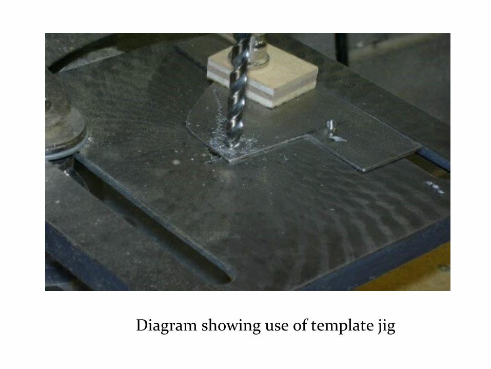
Diagram showing use of template jig

Box jig used for drilling holes at different points at different angles
8)- To drill holes at different angles- a) Box jig

Diagram showing box jig to drill hole at inclined angle, with unequal legs to give desired angle

Plate jig for drilling at an angle-
Angle plate jig for driiling at 90 degree
Modified angle plate jig for drilling at angle < 90 degree

6) For angular drill entry , angular plate jig with angular bush is used

7)-To drill holes on the irregular surfaces at different positions can be done by making end of bushing to the workpiece contour.

To make hole at one side of the flank , pot jig is used
POT JIGS

*leaf jig is used for drilling two connecting holes in small plate.
*It is a type of box jig with small size which surrounds the work and have a handle
LEAF JIG

Indexing jigs are used for accurately space holes around a circular part
INDEXING JIG

Problem 1
• Design and draw a channel jig for mild steel component as shown in the figure to drill a hole of 18 mm diameter

Different steps involved in design
• Selection of Bush• Selection of locator• Design of jig body• Selection of Clamps• Bill of Materials

Selection of Bush
• Outside diameter – Push fit or Press fit
• Inner hole – Run Fit
• Bush Selection, : headed fixed type DDB 5.100

• Given hole diameter is 18mm.• Tolerance for innter diameter
of bush: d1F7φ – running fit• From DDB 3.9 d1= 18 +0.041
+0.020
• d2=30 mm• Tolerance push fit- d2h6 φ• From ddb-3.7 d2= 30 +0.000
-0.016

Other dimensions
• l1= 20mm• l2= 15mm• d3= 35mm

Selection of locator
Thickness of jig plate must be equal to distance,l2 of brush= 15mm
For better rigidity- 2 locators and clamps on both sides are used
Select locating pin corresponding to jib plate thickness
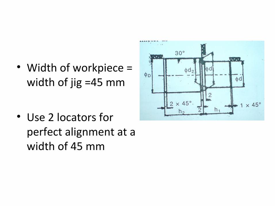
• Width of workpiece = width of jig =45 mm
• Use 2 locators for perfect alignment at a width of 45 mm

DDB 5.92
• Locator head diameter ,D= 16mm
• h1=14mmOther Dimensions
• d=15mm, • h1=14mm, • h2=22mm, • d1=12mm, • d2=11.5

Design of Jig Body
• W=45mm• Length of jig plate =
2tp+lw+h2+allowance = (2*15) + 75 + 22+ 13 = 140mm
• tp – thickness of jig plate
• Lw – length of workpiece

Continued Height of jig plate =
Hw + tp + clearance for chip removal = 52+15+ clearance
Clearance= 0.5 drill dia – for ductile= 1 drill dia – for brittle
So,height of jig plate=52+15+9 =76 mm

Selection of Clamp (DDB 5.104)
Pressure pad assembling is used to clamp right hand side of workpiece and fixed at the end of clamp.
2 clamps are selected for better rigidity

• Outer dia of pressure pad = d1 = 16mm
• Other dimensions
• d4 = 64mm
• f=3.5mm
• h = 9.5mm
• d5 = 12mm
• d6=7mm
• d7 = 2mm
• Size of screw M8


Bill of Materials
SL. NO Part Name Material No. o
1 Bush Gun Metal 1
2 Jig Plate Steel 1
3 Screw clamp with pressure pad
Steel 3
4 Locator Steel 2
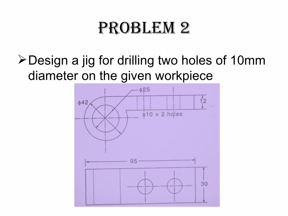
Problem 2
Design a jig for drilling two holes of 10mm diameter on the given workpiece

Step 1: Selection of bush
Fixed type bushes is selected (one for each hole to be drilled)
Inner hole - loose running fit (d1=10mm f7 )
Length of the bush (l1=20mm) l1=2xd1 (general rule)
Outer diameter - press fit(d2=18mm h6)
Flange diameter - 22mm
d1= 10 +0.034
+0.016
d2 = 18-0.000
-0.013

Step 2 : Design of locator and supporting block
For cylindrical workpiece, form locator is fabricated.
V-block locator may be used.
Drawback – height of jig will be increased

Used to support the workpiece from bending during drilling operation
Similar to hollow pipe
Supporting Block
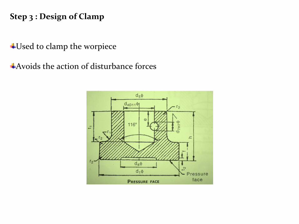
Step 3 : Design of Clamp
Used to clamp the worpiece
Avoids the action of disturbance forces


