

ARMY TM 5-830-3AIR FORCE AFM 88-17, CHAP. 3
TECHNICAL MANUAL
DUST CONTROL FOR ROADS, AIRFIELDS,AND ADJACENT AREAS
D E P A R T M E N T S O F T H E A R M Y A N D T H E A I R F O R C E
30 SEPTEMBER 1987

REPRODUCTION AUTHORIZATION/RESTRICTIONS
This manual has been prepared by or for the Government and is public property and not subject tocopyright.
Reprints or republications of this manual should include a credit substantially as follows: "JointDepartments of the Army and Air Force USA, Technical Manual TM 5-830-3/AFM 88-17, Chapter 3,Dust Control for Roads, Airfields, and Adjacent Areas, 30 September 1987."
TM 5-830-3/AFM 88-17, Chap. 3
TECHNICAL MANUAL HEADQUARTERSNo. 5-830-3 DEPARTMENTS OF THE ARMYAIR FORCE MANUAL AND THE AIR FORCEAFM 88-17, CHAPTER 3 WASHINGTON, DC, 30 SEPTEMBER 1987
DUST CONTROL FOR ROADS, AIRFIELDS,AND ADJACENT AREAS
Paragraph PageChapter 1. INTRODUCTION
Purpose....................................................................................................... 1-1 1-1Scope .......................................................................................................... 1-2 1-1Definition and cause.................................................................................... 1-3 1-1Factors influencing dust .............................................................................. 1-4 1-2Environmental factors ................................................................................. 1-5 1-2
Chapter 2. FACTORS FOR CONSIDERATIONGeneral ....................................................................................................... 2-1 2-1Intensity of area use.................................................................................... 2-2 2-1Topography ................................................................................................. 2-3 2-2Soil type....................................................................................................... 2-4 2-2Soil surface feature ..................................................................................... 2-5 2-2Climate ........................................................................................................ 2-6 2-3
Chapter 3. DUST CONTROL METHODSGeneral ....................................................................................................... 3-1 3-1Agronomic method...................................................................................... 3-2 3-1Surface penetration method........................................................................ 3-3 3-2Admix method ............................................................................................. 3-4 3-5Surface blanket method .............................................................................. 3-5 3-7
Chapter 4. DUST PALLIATIVESGeneral ....................................................................................................... 4-1 4-1Selection ..................................................................................................... 4-2 4-1Application rates.......................................................................................... 4-3 4-2Placement ................................................................................................... 4-4 4-3Dilution ........................................................................................................ 4-5 4-3Prewet ......................................................................................................... 4-6 4-4Cure ............................................................................................................ 4-7 4-8
Chapter 5. ECONOMICSGeneral ....................................................................................................... 5-1 5-1Economic factors ........................................................................................ 5-2 5-1Final selection ............................................................................................. 5-3 5-3
Appendix A. REFERENCES............................................................................................ A-1
Appendix B. CONTROL OF WINDBORNE SAND .......................................................... B-1
Bibliography .................................................................................................................... Biblio-1
*This manual supersedes TM 5-830-3/AFM 88-17, Chap. 3.30 September 1974.
i
TM 5-830-3/AFM 88-17, Chap. 3
LIST OF FIGURESFigure Page1-1. Three examples of typical dust clouds ............................................................................. 1-33-1. Special distributor for the three-step process for applying the
DCA 1295 .................................................................................................................. 3-93-2. Rolling frame for placing polypropylene fabric over the first coat of
asphalt emulsion........................................................................................................ 3-93-3. Polypropylene membrane layout for tangential sections.................................................. 3-103-4. Polypropylene membrane layout for curved sections....................................................... 3-105-1. Typical pump modifications for conventional asphalt distributor ...................................... 5-2B-1. Types of fixed sand dunes ............................................................................................... B-2B-2. Types of moving sand dunes ........................................................................................... B-3B-3. Cross section of dune showing initial and subsequent fences......................................... B-4B-4. Three fences installed to control dune formation ............................................................. B-4B-5. Three types of solid fencing or paneling for control of
dune formation. .......................................................................................................... B-5B-6. Schematic of dune destruction or stabilization by selective
treatment.................................................................................................................... B-6
LIST OF TABLESTable Page4-1. Dust Palliative Numbers for Dust Control in Nontraffic Area............................................ 4-24-2. Dust Palliative Numbers for Dust Control in Occasional
Traffic Area ................................................................................................................ 4-34-3. Dust Palliative Numbers for Dust Control in Traffic Area ................................................. 4-44-4. Dust Palliative Electives ................................................................................................... 4-5
ii
TM 5-830-3/AFM 88-17, Chap. 3
CHAPTER 1
INTRODUCTION
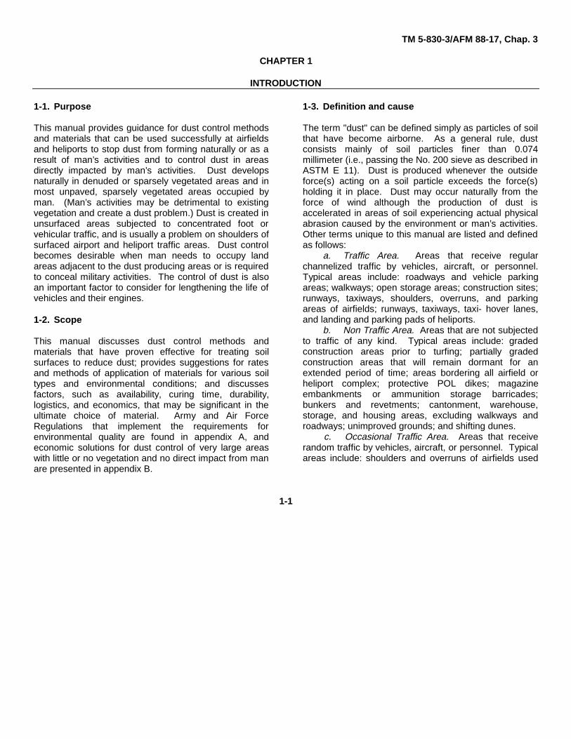
1-1. Purpose
This manual provides guidance for dust control methodsand materials that can be used successfully at airfieldsand heliports to stop dust from forming naturally or as aresult of man’s activities and to control dust in areasdirectly impacted by man’s activities. Dust developsnaturally in denuded or sparsely vegetated areas and inmost unpaved, sparsely vegetated areas occupied byman. (Man’s activities may be detrimental to existingvegetation and create a dust problem.) Dust is created inunsurfaced areas subjected to concentrated foot orvehicular traffic, and is usually a problem on shoulders ofsurfaced airport and heliport traffic areas. Dust controlbecomes desirable when man needs to occupy landareas adjacent to the dust producing areas or is requiredto conceal military activities. The control of dust is alsoan important factor to consider for lengthening the life ofvehicles and their engines.
1-2. Scope
This manual discusses dust control methods andmaterials that have proven effective for treating soilsurfaces to reduce dust; provides suggestions for ratesand methods of application of materials for various soiltypes and environmental conditions; and discussesfactors, such as availability, curing time, durability,logistics, and economics, that may be significant in theultimate choice of material. Army and Air ForceRegulations that implement the requirements forenvironmental quality are found in appendix A, andeconomic solutions for dust control of very large areaswith little or no vegetation and no direct impact from manare presented in appendix B.
1-3. Definition and cause
The term "dust" can be defined simply as particles of soilthat have become airborne. As a general rule, dustconsists mainly of soil particles finer than 0.074millimeter (i.e., passing the No. 200 sieve as described inASTM E 11). Dust is produced whenever the outsideforce(s) acting on a soil particle exceeds the force(s)holding it in place. Dust may occur naturally from theforce of wind although the production of dust isaccelerated in areas of soil experiencing actual physicalabrasion caused by the environment or man’s activities.Other terms unique to this manual are listed and definedas follows:
a. Traffic Area. Areas that receive regularchannelized traffic by vehicles, aircraft, or personnel.Typical areas include: roadways and vehicle parkingareas; walkways; open storage areas; construction sites;runways, taxiways, shoulders, overruns, and parkingareas of airfields; runways, taxiways, taxi- hover lanes,and landing and parking pads of heliports.
b. Non Traffic Area. Areas that are not subjectedto traffic of any kind. Typical areas include: gradedconstruction areas prior to turfing; partially gradedconstruction areas that will remain dormant for anextended period of time; areas bordering all airfield orheliport complex; protective POL dikes; magazineembankments or ammunition storage barricades;bunkers and revetments; cantonment, warehouse,storage, and housing areas, excluding walkways androadways; unimproved grounds; and shifting dunes.
c. Occasional Traffic Area. Areas that receiverandom traffic by vehicles, aircraft, or personnel. Typicalareas include: shoulders and overruns of airfields used
1-1
TM 5-830-3/AFM 88-17, Chap. 3
by propeller or jet air-craft, and shoulders, hover lanes,and peripheral areas of heliports and helipads.
d. Dust Palliative. A material applied to a soilsurface to prevent soil particles from becoming airborne.The user should note that many of the references listeduse the following additional terms to indicate a dustcontrol material: palliative, dustproofer, spray or soilstabilizer, soil waterproofer, dust control agent, and dustlayer.
e. Prewet. A light initial sprinkling of water on asoil surface prior to applying a liquid surface penetrant
f. Pertinent Areas. Soil areas that require aspecific dust palliative.
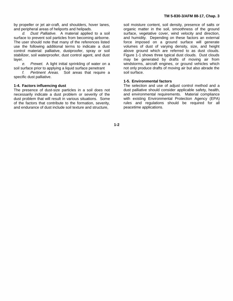
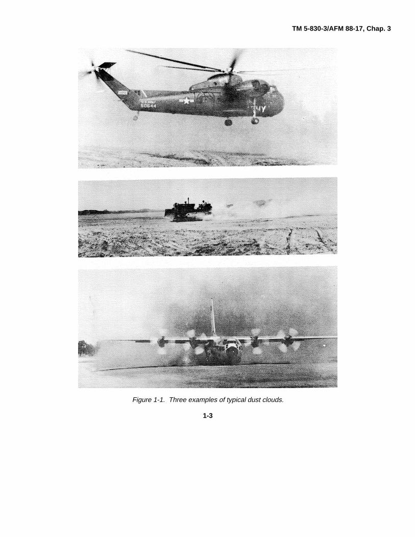
1-4. Factors influencing dustThe presence of dust-size particles in a soil does notnecessarily indicate a dust problem or severity of thedust problem that will result in various situations. Someof the factors that contribute to the formation, severity,and endurance of dust include soil texture and structure,
soil moisture content, soil density, presence of salts ororganic matter in the soil, smoothness of the groundsurface, vegetative cover, wind velocity and direction,and humidity. Depending on these factors an externalforce imposed on a ground surface will generatevolumes of dust of varying density, size, and heightabove ground which are referred to as dust clouds.Figure 1-1 shows three typical dust clouds. Dust cloudsmay be generated by drafts of moving air fromwindstorms, aircraft engines, or ground vehicles whichnot only produce drafts of moving air but also abrade thesoil surface.
1-5. Environmental factorsThe selection and use of adjust control method and adust palliative should consider applicable safety, health,and environmental requirements. Material compliancewith existing Environmental Protection Agency (EPA)rules and regulations should be required for allpeacetime applications.
1-2
TM 5-830-3/AFM 88-17, Chap. 3
Figure 1-1. Three examples of typical dust clouds.
1-3
TM 5-830-3/AFM 88-17, Chap. 3
CHAPTER 2
FACTORS FOR CONSIDERATION
2-1. GeneralA wide selection of dust palliatives for dust control isavailable to the engineer; however, no one material canbe singled out as being the most acceptable for allsituations. The successful control of dust and erosion inan area depend on several factors, the most important ofwhich are:
-Intensity of area use.-Topography.-Soil type.-Soil surface feature(s).-Climate.
2-2. Intensity of area use(expected traffic)The areas requiring treatment should be dividedaccording to the. amount of traffic expected: those withno traffic, with occasional traffic, and with channelizedtraffic (i.e., roadway or taxiway). Where the extent oftraffic can be predicted or regulated, significant savingsin time and material(s) may be realized by adjusting thetype and amount of treatment an area receivesaccording to use.
a. Nontraffic areas. These areas requiretreatment to withstand the effects of airblast due to windor nearby aircraft operations and are not subjected toactual traffic of any kind. If traffic is applied, the treatedarea may be damaged and repairs required. Typicalnontraffic areas include:
-Graded construction areas.’-Denuded areas around the periphery of completed
construction projects.-Areas .bordering airfield or heliport complexes.-Protective petroleum, oil and lubricant (PQL) dikes.-Magazine embankments of ammunition storage
barricades.-Bunkers and revetments.-Cantonment, warehouse, storage, and housing
areas, excluding walkways and roadways.-Unimproved grounds.-Areas experiencing windborne sand (see app B).b. Occasional traffic areas. Besides resisting
helicopter rotor downwash, aircraft propwash, andairblast from jet engines, these areas also are subjectedto occasional traffic by vehicles, aircraft, or personnel.Treatment for jet airblast is more involved than thatrequired for CH-47 helicopter downwash and C-130aircraft propwash; however, treatment for either will beadequate to support occasional, non-channelized,vehicular traffic. If traffic conditions change and multiplepasses or repeated crossings along the same pathoccur, the treated area may be damaged and repairsrequired. Typical occasional traffic areas include:
-Shoulders and overruns of airfields.-Shoulders, hover lanes, and peripheral areas of
heliports and helipads.-Areas mentioned in 2-2a where occasional traffic
becomes necessary.c. Traffic areas. These areas require treatment
to withstand regular channelized traffic by vehicles,aircraft, or personnel. Areas properly treated towithstand regular channelized traffic should easilywithstand airblasts from aircraft and helicraft. Typicaltraffic areas include:
-Roadways and vehicle parking areas.-Walkways.-Open storage areas.-Construction sites.--Runways, taxiways, shoulders.
*The method(s) and dust palliatives recommendedfor occasional traffic (table 4-2) are known to be effectivefor ground surface airblast and temperature of 80 mphand 120°F respectively.
2-1
TM 5-830-3/AFM 88-17, Chap. 3
overruns, and parking areas of airfields.-Runways, taxiways, taxi-hover lanes, and landing
and parking pads of heliports.-Tank trails.
Economic analysis of the cost to maintain an unsurfacedroad versus the costs associated with a paved surfaceroad indicates the break-even point occurs at a trafficlevel of approximately 100 vehicles per day. A durableriding surface such as an asphalt mixture or portlandcement concrete should be considered when unpavedroads are trafficked by 100 or more vehicles per day.Where these areas are considered permanent, theyshould be treated as specified in existing Army and AirForce publications.
2-3. Topographya. Distinction between flat and hillside areas. The
overall topography of the area should be considered aseither flat or hillside. Flat is defined as an averageground surface slope of 5 percent or less while hillsiderefers to an average ground surface slope steeper than 6percent. Emphasis is placed on the fact that the entiretopography of the area to be treated must be consideredand not specific spot localities. Spot areas can be givenspecial attention as needed.
b. Dust control for flat and hillside areas. Dustcontrol depends on the type of traffic expected, etc.;however, the final dust palliative selected may beaffected by the slope. For example, liquid dust controlmaterials may tend to flow instead of penetrate or form aprotective cover over the dusty area.
2-4. Soil typeThe soil type is one of the key features used todetermine which method and material should be used fordust control. Soils to be treated for dust control havebeen placed into five general descriptive groupingsbased On the Unified Soil Classification System (USCS),MIL-STD-619B.
a. Silts or clays (high liquid limit). The relativelyimpervious, plastic, fine-grained soils encompass USCStypes CH, OH, and MH.
b. Silts or clays (low liquid limit). The moderatelypermeable, low to medium plasticity, fine-grained soilsencompass USCS types ML, CL ML-CL, and OL.
c. Sands or gravels (with fines). The moderatelypermeable, coarse-grained soils contain an appreciableamount of fines encompassing USCS types SM, SC,SM-SC, GM, GC, GM-GC, and GW-GM. CL Sands (withlittle or no fines). The highly permeable sands or gravellysands contain little or no fines encompassing USCStypes SW-SM, SP, and SW.
e. Gravels (with little or no fines). The highlypermeable gravels or sandy gravels contain little or nofines encompassing USCS types GP and GW.
2-5. Soil surface featureSoil surface features refer to both the state ofcompaction and degree of saturation of the soil in thearea being considered.
a. Loose and dry or slightly damp. The surfaceconsists of a blanket, 1/4 to 2 inches thick, of unbound oruncompacted soil overlying a relatively firm subgradeand ranging in moisture content from dry to slightlydamp.
b. Loose and wet or slurry. A surface conditionconsists of a blanket, 1/4 to 2 inches thick, of unbound oruncompacted soil overlying a soft to firm subgrade andranging in moisture content from wet to slurryconsistency. Soil in this state cannot be treated until it isdried to the condition defined in either paragraph aboveor below.
c. Firm and dry or slightly damp. The surfacecondition consists of less than 1/4-inch-thick layer ofloose soil ranging in moisture content from dry to slightlydamp overlying a bound or compacted firm soilsubgrade.
d. Firm and wet. This surface condition is similarto that defined in paragraph c but has a wet surface. Soilin this condition cannot be treated until it is dried to thecondition defined.
e. Treatment ability. The soil surface featuredescribed in paragraph a is acceptable for treatment fordust control where no traffic or only occasional traffic isexpected. The soil surface feature described inparagraph c is acceptable for treatment for dust control
2-2
TM 5-830-3/AFM 88-17, Chap. 3
regardless of the expected traffic. The soil surfacefeatures described in paragraph b and d cannot betreated and do not need treatment for dust control in thestated condition. Normal earth moving methods can beemployed in most situations to upgrade dust producingareas to the condition described in paragraph c.
2-6. Climatea. The climate in the area where dust control is
desired could adversely affect the dust palliative(s)during storage (prior to placement), during placement(the construction and/or cure period), and afterplacement. The climate at the time of placement andafter placement should be considered by the designerbefore adjust palliative is selected.
b. Weather extremes accelerate the aging and/ordeterioration of most materials and dust palliatives areno exception. Many of the liquid dust palliatives must bestored, placed, and permitted to cure at temperaturesabove 40 degrees Fahrenheit. Agronomic methodsshould be initiated at the onset of the growing seasonwhich may be limited to a few weeks. Some dustpalliatives become brittle when exposed to extreme coldand should not be trafficked during these periods, whileothers leach from the soil during rain storms. Attemperatures above 90 degrees Fahrenheit manybituminous products become tacky. Salts becomeineffective during extended periods of no rainfallwhenever the humidity falls below approximately 30percent.
2-3
TM 5-830-3/AFM 88-17, Chap. 3
CHAPTER 3
DUST CONTROL METHODS
3-1. GeneralThis chapter describes several types of dust palliativesthat are commercially available; special care that mustbe used with a dust palliative; type of traffic areas wherea dust palliative is applicable; and references as to wheremore details on the proper use and application of thedust palliative can be obtained. Each dust controlmethod should be considered in relation to the specificjob requirements. The four general dust controltreatment methods commonly used are:
-Agronomic.-Surface penetrant.-Admix.-Surface blanket.
The surface penetrant and surface blanket methods arethe easiest to apply. Application of either methodrequires a material placement procedure (i.e., spreadingaggregate or membrane over the area) or a materialspraying procedure. One of these two methods willprobably suffice for the majority of dust control cases.The other two methods are much more involved andrequire more time and equipment to implement., Theagronomic method requires a knowledge of theindigenous vegetation and access to farm typeequipment. The admix method requires standard roadbuilding techniques using construction equipment.Application may require specific handling, equipment,and procedures. The manufacturer’s precautions shouldbe adhered to with the use of personnel protectiveequipment (masks, safety glasses, gloves, etc.) asrequired.
3-2. Agronomic methodsa. This method consists of establishing or
extending and preserving vegetative cover, mulch,
shelter belts, and rough-tillage. It includes such items asseeding, sprigging, sodding, topsoiling, fertilizing,mulching, and disking. Agronomic methods are notnormally prescribed for traffic areas.
b. Occasionally large areas are cleared forproposed projects, stripping the project area of the nativegrass and all topsoil. The extent of stripping should bekept to a minimum and the stripped topsoil withvegetative residue stock-piled for later placement aroundthe completed structure(s) and/or use on other denudedareas.
(1) Vegetative cover. Vegetative cover isoften considered the most satisfactory form of dustpalliative based on aesthetic aspects, durability, cost,and maintenance. Indeed this is the preferred methodwherever it can be economically established andmaintained. Areas of application are best limited tonontraffic areas. Where vegetative cover is to beultimately established, any dust palliative used forimmediate surface protection should be selected with aview of minimizing impairment to subsequent plantgrowth. While dense vegetation is certainly the mosteffective cover, more sparse native vegetation typical ofsemiarid and arid regions can be a fully effective dustpalliative under natural wind conditions so long as it isnot damaged by traffic or other causes.
(2) Mulch. A well-anchored mulch ofvegetative material .can be used to stabilize soil againstwind and water erosion. Mulch refers to any substance,such as straw, hay, paper, or brushwood, that is spreadover the ground surface to protect it from the wind.Vegetative mulches are normally effective for 1 year andcan be applied during any season. Mulches are normallyspread by either a beater or blower type, spreader. Theblower type has the advantage in that it is
3-1
TM 5-830-3/AFM 88-17, Chap. 3
normally equipped with an asphalt spraying mechanismfor anchoring the mulch. It can place the mulch andasphalt at the same time and at considerable distancefrom the operating location. Otherwise, anchoring isnormally accomplished with either a disk packer or V-tread rolling wheel packer. Rapid curing (RC) cutbacksor rapid setting (RS) asphalt emulsions are normallyused for anchoring, since they are more effective thanthe slower curing materials. In an emergency, vegetativemulch can be anchored by applying a jet of water to burypart of the mulch in the soil. About 2,000 gallons ofwater per acre is needed to provide maximumanchorage. Mulch is undesirable around airports since itmay be ingested into jet engines. Further details on therecommended uses and methods of applying a widevariety of mulches are discussed in TM 5-830-2/AFM 88-17, Chapter 2; TM 5-630/AFM 126-2; and Department ofAgriculture Hand- book No. 346.
(3) Shelter belts. Any barrier of hedges,shrubs, or trees high and dense enough to protectfacilities and unsurfaced soil areas is considered to be ashelter belt or windbreak. Shelter belts should be placedat right angles to the direction of the prevailing wind.Several parallel shelter belts may be required and usuallythe higher the average wind velocity the closer theshelter belts should be spaced. While such shelter beltscan serve occupied areas, their practical applicabilitysolely for dust control is limited. Trees are slow tobecome established, and additional soil treatmentbetween tree belts is usually required. Finally, insemiarid regions, where shelter belts or windbreaks aremost highly valued, trees often cannot be sustainedwithout irrigation. Notwithstanding the above limitations,shelter belts can supplement other dust-controlmeasures by reducing wind velocity. The use of shelterbelts are recommended wherever they do not interferewith the intended area activities.
(4) Rough tillage. Chisels, listers, and turningplows are used to till strips across nontraffic areas thathave become sources of dust. Several strips are placedin parallel as an emergency measure to control dust in
semiarid regions. The soil should be cohesive enough toproduce soil clods (lumps of earth with a minimumdimension of 1 inch measured in any direction). Stripsshould be tilled at 25- to 100-foot intervals at right anglesto the prevailing wind. As the strips become smooththrough erosion, new strips should be plowed adjacent tothe earlier ones. The success of this method dependsupon the formation of a cloddy, rough surface thatbreaks up the sweep of soil particles. Tillage of dry soiltypical of desert areas sometimes may be harmful ratherthan beneficial to dust control if a cloddy surface is notproduced. Rough tillage is normally considered atemporary control measure to be followed by permanentvegetative cover, but it sometimes can be sufficient asthe only treatment if traffic is excluded from the area andthe native vegetation is capable of regeneration. Disk-type tillage tools generally should not be used for roughtillage as they tend to pulverize the soil too much (i.e.,soil clods are not formed). However, if long narrowgrooves are created which would channel runoff water,the tillage should be laid out on horizontal contours toprevent water damage.
3-3. Surface penetration methodIn the surface penetration method, the dust palliative, aliquid, is applied directly on the soil surface by sprayingor sprinkling and allowed to penetrate the surface underits own accord. Surface penetration applications may beaccomplished with a liquid pressure distributor, by agravity-flow water distributor, or by hand-held devices.The spray apparatus should be positioned directly abovethe area being treated (8-14 inches) to preclude, wind-drift. Runoff should be avoided (if necessary bydecreasing the application rate or applying the dustpalliative at one-half the recommended rate andrepeating the treatment later).
a. Effectiveness. The effectiveness of thesurface penetration method depends on the depth ofpenetration which is a function of the viscosity of the dust
3-2
TM 5-830-3/AFM 88-17, Chap. 3
palliative and the permeability of the soil. Penetration isfacilitated by sprinkling (prewetting) the surface withwater prior to applying the dust palliative. This procedurereduces surface tension and helps assure a uniformcoverage and maximum penetration.
b. Pertinent areas. A soil penetrant can be usedin all nontraffic areas provided the other factors forconsideration (chapter 2) are met. This method will alsoprove effective for occasional traffic areas (with the same"factors limitation" noted above) provided the treated soilis strong enough or has been conditioned for the stateduse. Very few dust palliatives used as a penetrant impartany additional strength to the treated soil. A soil that willrut before treatment will surely rut after treatment, aprocess that will quickly render the treatment ineffective.In planned traffic areas a dust palliative penetrant willonly prove effective on prepared areas (e.g., onunsurfaced gravel roads).
c. Types of materials. Dust palliatives thatpenetrate the soil surface include bitumens, resins, salts,and water.
(1) Bituminous materials. Conventional typesof bituminous materials that may be used for dustpalliatives include cutback asphalts, emulsified asphalts,and road tars. These materials can be used to treat bothtraffic and nontraffic areas. All bituminous materials donot cure at the same rate. This fact may be ofimportance when they are being considered’ for use intraffic areas. Also, bituminous materials are sensitive toweather extremes. Usually bituminous materials impartsome waterproofing to the treated area that remainseffective as long as the treatment remains intact (i.e., asplaced or as applied). Bituminous materials should notbe placed in the rain or when rain is threatening.
(a) Cutback asphalts. A cutback asphalt(cutbacks) is a blend of an asphalt cement and apetroleum solvent. These cutbacks are classified asrapid curing (RC), medium curing (MC), and slow curing(SC), depending on the type of solvent used and its rateof evaporation. Each cutback is further graded by its
viscosity. The RC and SC grades of 70 and 250,respectively, and MC grades of 30, 70, and 250 aregenerally used. Regardless of classification or grade thebest results are obtained by preheating the cutback.Spraying temperatures usually range from 120 to 300degrees Fahrenheit. The actual range for a particularcutback is much narrower and should be requested fromthe supplier at the time of purchase. The user iscautioned that some cutbacks must be heated abovetheir flash point for spraying purposes and therefore nosmoking or open flames should be permitted duringapplication or cure. MC-30 grade can be sprayedwithout being heated if the temperature of the asphalt is80 degrees Fahrenheit or above. A slightly moist soilsurface will assist penetration. Curing time for cutbacksvaries with the type. Under favorable groundtemperature and weather conditions RC cures in 1 hour,MC in 3 to 6 hours, and SC in 1 to 3 days. In selectingthe material for use, local environmental protectionregulations must be considered.
(b) Emulsified asphalts. Asphaltemulsions (emulsions) are a blend of asphalt, water, andan emulsifying agent and are available either as ionic orcationic emulsions. The application of emulsions atambient temperatures of 80 degrees Fahrenheit orabove gives the best results. Satisfactory results may beobtained below this temperature, especially if applicationis made in the morning to permit the warming effects ofthe afternoon sun to aid in curing. Emulsions should notbe placed at temperatures below 50 degrees Fahrenheit.Emulsions placed at temperatures below freezing willfreeze, producing a substandard product. For bestresults in a freezing environment, emulsions should beheated to between 75 degrees and 130 degreesFahrenheit. The temperature of the material shouldnever exceed the upper heating limit of 185 degreesFahrenheit because the asphalt and water will separate(break), resulting in material damage. Emulsionsgenerally cure in about 8 hours. The slow setting anionicemulsions of grades SS-1 and SS-1h may be diluted
3-3

TM 5-830-3/AFM 88-17, Chap. 3
with 1 to 5 or more parts water to one part emulsifiedasphalt by volume prior to use. As a general rule, a 3part water to 1 part emulsion dilution is satisfactory formost applications. The slow-setting cationic emulsionsof grades CSS-1 and CSS-1h are easiest to use withoutdilution. If dilution is desired, the water used must befree of any impurities, minerals, or salts that might causeseparation (breaking) of the emulsion within thedistribution equipment.
(c) Road tars. Road tars (tars) areviscous liquids obtained by distillation of crude tarsobtained from coal. Tars derived from other basicmaterials are also available, but are not normally used assoil treatments. Tars are graded by viscosity andavailable in grades ranging from 1 to 12. Tars are alsoavailable in the cutback (RTCB) form of viscosity grades5 and 6, and in the emulsified form. Tar emulsions aredifficult to prepare and handle. The low viscosity gradesRT-1 and RT-2 and the RTCB grades can be applied attemperatures as low as 60 degrees Fahrenheit withoutheating. The tar cutbacks generally have betterpenetrating characteristics than asphalts and willnormally cure in a few hours. Tars will produce excellentsurfaces, but curing proceeds very slowly, and severaldays or even weeks may be required to obtain acompletely cured layer. Tars are susceptible totemperature changes and may soften in hot weather orbecome brittle in cold weather.
(d) Asphaltic penetrative soil binder(APSB). This commercial product is a special liquidasphalt composed of high penetration grade asphalt anda solvent blend of kerosene and naphtha. It is similar incharacter to a standard low viscosity, medium curingliquid asphalt, but differs in many specific properties.The APSB is suitable for application to soils that arerelatively impervious to conventional liquid asphalts andemulsion systems. Silts and moderately plastic clays (toa plasticity index of 15) can be treated effectively. Curingtime for the APSB is 6 to 12 hours under favorableground temperature and weather conditions. On highplasticity solids (plasticity index greater than 15), the
material will remain on the surface as an asphalt film thatis tacky at a ground temperature of approximately 100degrees Fahrenheit and above. The APSB must beheated to a temperature between 130 and 150 degreesFahrenheit to permit spraying with an asphalt distributor.
(2) Resinous materials. These dustpalliatives may be used as either surface penetrants orsurface blankets as they have a tendency to eitherpenetrate the surface or form a thin surface filmdepending on the type used, the soil type, and the soilcondition. The materials are normally applicable tonontraffic areas and occasional traffic areas whererutting will not occur. They are not recommended for usewith silts and clays.
(a) Resin-petroleum-water emulsion.Resin petroleum water emulsions are quite stable andhighly resistant to weathering. A feature of this type dustpalliative is that the soil remains readily permeable towater after it is treated. This type of product is principallymanufactured under the trade name Coherex.Application rates range from 0.33 to 0.5 gallon persquare yard. The material may be diluted 4 parts waterto 1 part concentrate for spraying. This material isprimarily suited for dry sandy soils and has been found toprovide unsuitable results when used on silty and clayeysoils.
(b) Lignin. Lignin is a by-product of themanufacture of wood pulp. It is soluble in water andtherefore readily penetrates the soil. Its solubility alsomakes it susceptible to leaching from the soil; thusapplication is repeated as necessary after rainfall. Ligninis readily available in the continental United States andcertain other sections of the world, and has utility inareas where dust control is desirable for short periods oftime. It is not recommended for use where durability is,an important factor. Application at a rate of 1 gallon persquare yard of a resinous solution of 8 percent solidlignin sulphite is recommended.
3-4
TM 5-830-3/AFM 88-17, Chap. 3
(c) Concrete curing compounds.Concrete curing compounds can be used to penetratesands which contain little or no silts or clays. Thismaterial should be limited to areas of no traffic. The highcost of this material is partly offset by the low applicationrate required (0.1 to 0.2 gallon per square yard).Standard asphalt pressure distributors can be used toapply the resin, but the conventional spray nozzlesshould be replaced with smaller opening spray nozzles toachieve a uniform distribution at the low application rate.
(3) Brine materials. Salts in water emulsionshave been used with varying success as dust palliatives.Dry calcium chloride is deliquescent and is effectivewhen the relative humidity is about 30 percent or greater.A calcium chloride treated soil will retain more moisturethan the untreated soil under comparable dryingconditions. Its use is limited to occasional traffic areas.Sodium chloride achieves some dust control by retainingmoisture and also by some cementing from saltcrystallization. Both calcium chloride and sodiumchloride are soluble in water and are readily leachedfrom the soil surface; thus frequent maintenance isrequired. Continued applications of salt solutions canultimately build up a thin, crusted surface that will befairly hard and free of dust. Most salts are corrosive tometal and should not be stored in the vehicle used forapplication. Magnesium chloride will control dust ongravel roads with tracked vehicle traffic. Best results canbe, expected in areas with occasional rainfall or wherethe humidity is above about 30 percent. The dustpalliative selected and the quantity used should notexceed local environmental protection regulations.
(4) Water. As a commonly used but verytemporary measure for allaying; dust, a soil surface canbe sprinkled with water. As long as the ground surfaceremains moist or damp, soil particles will resist becomingairborne. Depending on the soil and climate, frequenttreatment may be required. Water should not be appliedto clay soil surfaces in such quantity that puddles form,since a muddy or slippery surface may result where thesoil remains-wet.
3-4. Admix methodIn the admix method, the dust palliative is blended withthe soil to produce a uniform mixture. This method takesmore effort, time, and equipment than the penetrationand surface blanket methods, however, it also increasessoil strength.
a. Depth of treatment. A minimum treatment of 3inches will be satisfactory for all nontraffic areas. Toprovide a dustproof surface in traffic areas, a minimumtreatment depth of 4 inches is recommended. Admixingcan be accomplished in-place or offsite and is adaptableto a large variety of soil types, (The admix method is notparticularly suitable for areas where a vegetative cover isto be established.)
b. Types of materials. Two types of admixmaterials may be used as dust palliatives:
-Powders - Portland cement, hydrated lime-Liquids - Bituminous materials including cutback
asphalt, emulsified asphalt, and road tars.c. In-place admixing. In-place admixing is the
blending of soil and dust palliative on the site. Thesurface soil is loosened (if necessary) to a depth slightlygreater than the desired thick- ness of the treated layer.The dust palliative is added and blended with theloosened surface soil, and the mixture is compacted.Powders may be spread by hand or a mechanicalspreader, and liquids should be applied with an asphaltdistributor. Mixing equipment that can be used includesrotary tillers, rotary pulverizer-mixers, graders, scarifiers,disk harrows, or plows. Admixing and/or blending shouldcontinue until a uniform color of soil and dust palliativemixture, both horizontally and vertically, is achieved. Themost effective compaction equipment that can be usedare sheepsfoot or rubber-tired rollers. The procedure forin-place admixing closely resembles the soil stabilizationprocedure for changing soil characteristics and soilstrength used in road
3-5
TM 5-830-3/AFM 88-17, Chap. 3
construction. For dust control on a nontraffic area,adequate compaction can be achieved by trafficking theentire surface with a 5-ton dual wheel truck. For all othertraffic situations the procedure should follow TM 5-822-4.This procedure is time consuming and requires the useof more equipment than the other three. Followingplacement, admixing, and compaction a minimum of 7days is required for curing.
(1) Cementing materials. Two cementingtype powders (portland cement and hydrated lime) areprimarily used to improve the strength of soils. However,when they are admixed with soils in relatively smallquantities (2 to 5 percent by dry soil weight), the modifiedsoil is resistant to dusting. Portland cement is generallysuited for all soil types, provided uniform mixing can beachieved; whereas hydrated lime is applicable only tosoils containing a high percentage of clay. Thecompacted soil surface should be kept moist for aminimum of 7 days prior to traffic.
(2) Bituminous materials. Bituminousmaterials are more versatile than cementing materials inproviding adequate dust control and waterproofing thesoil. Cutbacks, emulsion asphalts, and road tars can allbe used successfully. The quantities of residualbituminous material used should range from 2 to 3percent of dry soil weight for soils having less than 30percent passing the No. 200 sieve to 6 to 8 percent forsoils having more than 30 percent fine-grained passingthe No. 200 sieve. The presence of mica in a soil isdetrimental to the effectiveness of a soil-bituminousmaterial admixture. There are no simple guides orshortcuts for designing mixtures of soil and bituminousmaterials. The maximum effectiveness of soil-bituminous material admixtures can usually be achievedif the soil characteristics are within the following limits:
Plasticity Index: equal to orless than 10
Percent of material equal to orpassing No. 200 less thansieve: 30 percent
by weight
These data and additional construction data can befound in TM 5-822-4. Traffic should be detoured aroundthe treated area until the soil-bituminous materialadmixture has cured.
(a) Cutback asphalt. When admixed intosoil to depths of 3 inches or more on a firm subgrade,cutback asphalt will provide a dust free, waterproofsurface. More satisfactory results will be obtained if thecutback asphalt is preheated prior to use. Soils shouldbe fairly dry when cutback asphalts are admixed. Whenusing SC or MC types of cutback asphalt, it is necessaryto aerate the soil-asphalt mixture to allow the volatiles toevaporate. Also see paragraph 3-3c(1)(a).
(b) Emulsified asphalts. Emulsifiedasphalts are admixed with a conditioned soil that willallow the emulsion to break prior to compaction. Aproperly conditioned soil should have a soil moisturecontent not to exceed 5 percent in soils having less than30 percent passing the No. 200 sieve. Emulsifiedasphalts, particularly the cationics, are extremelysensitive. When they (CSS-1 or CSS-1h) are usedimproperly, the emulsion may break prematurely or aftersome delay. The slow-setting anionic emulsions ofgrades are less sensitive.See also paragraph 3-3c(1)(b).
(c) Road tars. Road tars grade RT andRTCB can be used as admixtures in the same manneras other bituminous materials. Road tar admixtures aresusceptible to temperature changes and may soften inhot weather or become brittle in cold weather. See alsoparagraph 3-3c(1)(c).
d. Offsite admixing. Offsite admixing is generallyused where in-place ad- mixing is not desirable and/orsoil from another source provides a more satisfactorytreated surface. Offsite admixing may be accomplishedwith a stationary mixing plant, or by windrow mixing withgraders in a central working area. Processing the soiland dust palliative through a central plant produces amore uniform mixture than in-place admixing. The majordisadvantage in any offsite operation is having totransport and spread the mixed material.
3-6
TM 5-830-3/AFM 88-17, Chap. 3
3-5. Surface- blanket methodThis method includes the use of aggregates,prefabricated membranes and mesh, bituminous surfacetreatments, polyvinyl acetates (with and withoutfiberglass scrim reinforcement), and polypropylene-asphalt membranes to create a surface blanket for dustcontrol. The type of treatment used will dictate theequipment required. However, standard constructionequipment in all cases can be used effectively to placeany of the systems applicable to the surface blanketmethod. Mechanized equipment should be usedwherever possible to assure uniformity of treatment.
a. Effectiveness. The surface blanket method isapplicable to nontraffic, occasional traffic, and trafficareas. Aggregate, prefabricated membrane, and meshtreatments are easy to place and can withstandconsiderable rutting. The other surface blanket methodswill only withstand minimal rutting. Once a surfaceblanket treatment is torn or otherwise compromised, andthe soil exposed, subsequent traffic or airblast willincrease the damage to the torn surface blanket whileproducing dust from the exposed soil. Repairs(maintenance) should begin as soon as possible toprotect the material in place and keep the dustcontrolled. Three types of materials may be used assurface blankets:
-Mineral aggregates.-Synthetics membranes or meshes.-Liquids Bituminous or polyvinyl
acetate liquids.b. These materials may be used alone or in the
combinations discussed below.(1) Aggregates. In arid areas where most
vegetative covers do not survive because of low rainfall,crushed or uncrushed gravel, slag, or tone aggregate (2inches maximum size) can be used as a dust palliativeon non- traffic or occasional traffic areas. Aggregate isnot recommended in close proximity to aircraft trafficbecause gravel particles may be picked up and thrownby airblast with possible damage to aircraft and ground
personnel. Aggregate should be spread in a layer about2 inches thick and should contain at least 80 percent byweight of particles retained on the 1/4-inch screen.Traffic over aggregate blanketed areas tends to pressthe material into the soil and pulverize the surface;therefore this treatment is not recommended wherechannelized traffic is expected.
(2) Prefabricated membrane. Membraneused to surface an area will control dust and even act asa surface course or riding surface for traffic that does notrut the soil. When subjected to traffic, the membranecan be expected to last approximately 5 years. Minorrepairs can be made easily. For optimum anchorage,the membrane should be extended into 2-foot-deepditches at each edge of the covered area; staked inplace and the ditches backfilled. Further details on theuse and installation of prefabricated membranes can beobtained from TM 5-330/AFM 86-3, Volume II.
(3) Prefabricated mesh. Heavy woven jutemesh such as commonly used in conjunction with grassseed operations can be used for dust control of nontrafficareas. The mesh should be secured to the soil byburying the edges in trenches and by using large U-shaped staples that are driven flush with the soil surface.A minimum overlap of 3 inches should be used in joiningrolls of mesh. After being placed, the mesh and coveredsoil should be sprayed with a bituminous material. Trialapplications are recommended at each site and shouldbe adjusted to suit each job situation.
(4) Bituminous surface treatments. Single ordouble bituminous surface treatments can be used tocontrol dust on most soils. A medium-curing liquidasphalt is ordinarily used to prime the soil prior toplacement of the surface treatment. Fine-grained soilsare generally primed with MC-30, and coarse-grainedsoils with MC-70. After the prime coat has cured, abituminous material is uniformly applied and gravel, slag,or stone aggregate spread over the treated area atapproximately 25 pounds of aggregate per square yard.
3-7
TM 5-830-3/AFM 88-17, Chap. 3
Types of bituminous materials, aggregate gradations,application rates, and methods of placing surfacetreatments are described in TM 5-822-8/AFM 88-6,Chapter 9. Single or double bituminous surfacetreatments should not be used where turf is to beestablished.
(5) Polyvinyl acetates (DCA 1295). DCA1295 has a slight odor and an appearance similar tolatex paint. The material is diluted 3 parts DCA 1295 to1 part water and cures in 2 to 4 hours under idealconditions of moderate to high temperature and lowrelative humidity. A clear, flexible, film forms on thetreated surface. DCA 1295 can be sprayed with aconventional asphalt distributor provided modificationsare made to the pump to permit external lubrication. TheDCA 1295 can be used alone or over fiberglassreinforcement. The addition of fiberglass does not affectthe basic application procedures or the curingcharacteristics of the DCA 1295. This material issuitable for use on nontraffic, occasional traffic, andtraffic areas. This material has also been found to beeffective when sprayed over grass seed to protect thesoil until growth occurs. Uniform soil coverage isenhanced by sprinkling (prewetting) the surface withwater.
(6) Polyvinyl acetate (DCA 1295) withreinforcement. A fiberglass scrim material isrecommended for use with the DCA 1295 when areinforcement is desired. Fiberglass scrim increases theexpected life of the dust-control film by reducing theexpansion and con- traction effects of weather extremes.The scrim material should be composed of fiberglassthreads having a plain weave pattern of 10 by 10 (tenthreads per inch in the warp direction and ten threads perinch in the fill direction), having a greige finish, andshould weigh approximately 1.6 ounces per square yard.The use of scrim material does not create any health orsafety hazards, and special storage facilities are notrequired. Scrim materials can be applied under anyclimatic conditions suitable for dispensing the DCA 1295.(Under special conditions, continuous strands of fiber-glass may be chopped into 1/2-inch-long segments and
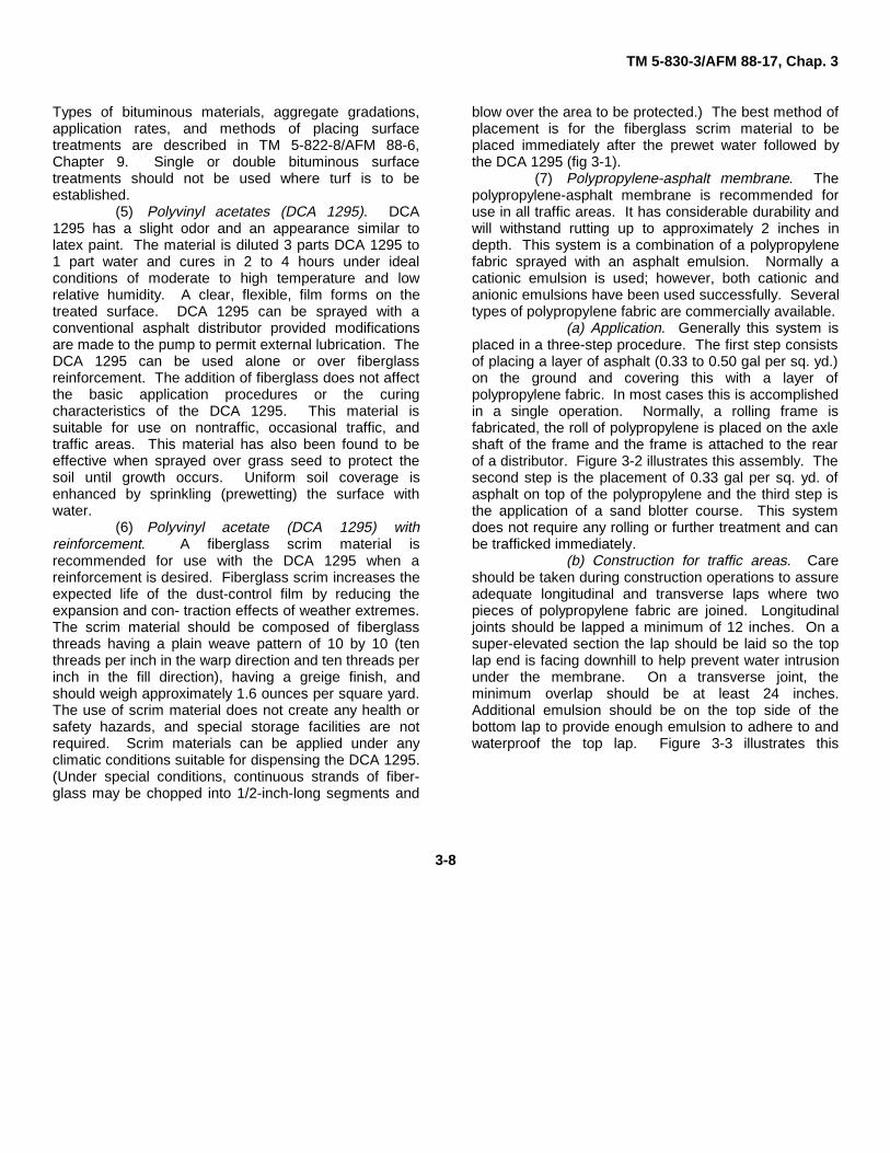
blow over the area to be protected.) The best method ofplacement is for the fiberglass scrim material to beplaced immediately after the prewet water followed bythe DCA 1295 (fig 3-1).
(7) Polypropylene-asphalt membrane. Thepolypropylene-asphalt membrane is recommended foruse in all traffic areas. It has considerable durability andwill withstand rutting up to approximately 2 inches indepth. This system is a combination of a polypropylenefabric sprayed with an asphalt emulsion. Normally acationic emulsion is used; however, both cationic andanionic emulsions have been used successfully. Severaltypes of polypropylene fabric are commercially available.
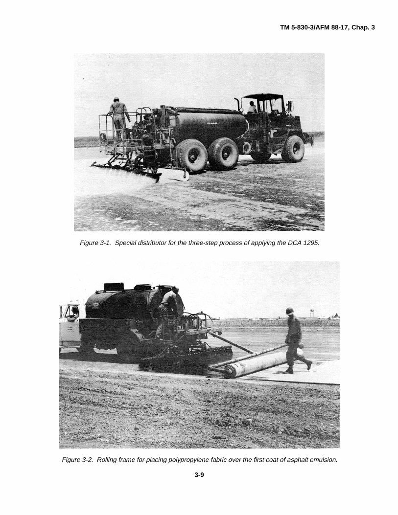
(a) Application. Generally this system isplaced in a three-step procedure. The first step consistsof placing a layer of asphalt (0.33 to 0.50 gal per sq. yd.)on the ground and covering this with a layer ofpolypropylene fabric. In most cases this is accomplishedin a single operation. Normally, a rolling frame isfabricated, the roll of polypropylene is placed on the axleshaft of the frame and the frame is attached to the rearof a distributor. Figure 3-2 illustrates this assembly. Thesecond step is the placement of 0.33 gal per sq. yd. ofasphalt on top of the polypropylene and the third step isthe application of a sand blotter course. This systemdoes not require any rolling or further treatment and canbe trafficked immediately.
(b) Construction for traffic areas. Careshould be taken during construction operations to assureadequate longitudinal and transverse laps where twopieces of polypropylene fabric are joined. Longitudinaljoints should be lapped a minimum of 12 inches. On asuper-elevated section the lap should be laid so the toplap end is facing downhill to help prevent water intrusionunder the membrane. On a transverse joint, theminimum overlap should be at least 24 inches.Additional emulsion should be on the top side of thebottom lap to provide enough emulsion to adhere to andwaterproof the top lap. Figure 3-3 illustrates this
3-8
TM 5-830-3/AFM 88-17, Chap. 3
Figure 3-1. Special distributor for the three-step process of applying the DCA 1295.
Figure 3-2. Rolling frame for placing polypropylene fabric over the first coat of asphalt emulsion.
3-9

TM 5-830-3/AFM 88-17, Chap. 3
process on tangential sections. Application ofpolypropylene on roadway curves requires cutting and
placing the fabric as shown in figure 3-4. The joints incurved areas should be overlapped a minimum of 24inches.
Figure 3-3. Polypropylene membrane layout for tangential sections.
Figure 3-4. Polypropylene membrane layout for curved sections.
3-10
TM 5-830-3/AFM 88-17, Chap. 3
CHAPTER 4
DUST PALLIATIVES
4-1. Generala. The primary objective of a dust palliative is to
prevent soil particles from becoming airborne. Dustpalliatives may be required for the control of dust onnontraffic or traffic areas, or both. For nontraffic, adjustpalliative is needed that is capable of resisting themaximum intensity of airblast impingement caused byweather or (nearby) aircraft. For traffic areas, a dustpalliative must withstand the abrasion of wheels (andpossibly tracks) in addition to airblast. Although a dustpalliative may provide the necessary resistance againstair impingement, it may be totally unsuitable as awearing surface. An important factor limiting theapplicability of a dust palliative in traffic areas is theextent of surface rutting that will occur under traffic.(Rutting occurs if the bearing capacity of the soil is suchthat the soil surface depresses or com- pacts as a resultof vehicle traffic.) The effectiveness of a dust palliativetreatment is destroyed rapidly by rutting and anyremaining dust palliative is quickly stripped from theground surface. Some palliatives will toleratedeformations better than others, but normally ruts of 1 to1-1/2 inches will result in the destruction of any treatmentmethod.
b. Many times a dust palliative also functions as asoil water proofer. When this occurs, the dust palliativenot only prevents dust but also preserver, the in-place oras-constructed soil strength during wet weatherconditions The judicious selection of soil waterproofers isbeyond the scope of this manual.
c. Some dust palliatives may be harmful toexisting vegetation and/or make it difficult to establishvegetation in areas previously treated. Some dustpalliatives trap soil moisture and increase soiltemperature thus promoting vegetative growth. The dust
palliatives presented herein will not harm adjacentvegetation as long as wind-drift and runoff duringplacement are prevented.
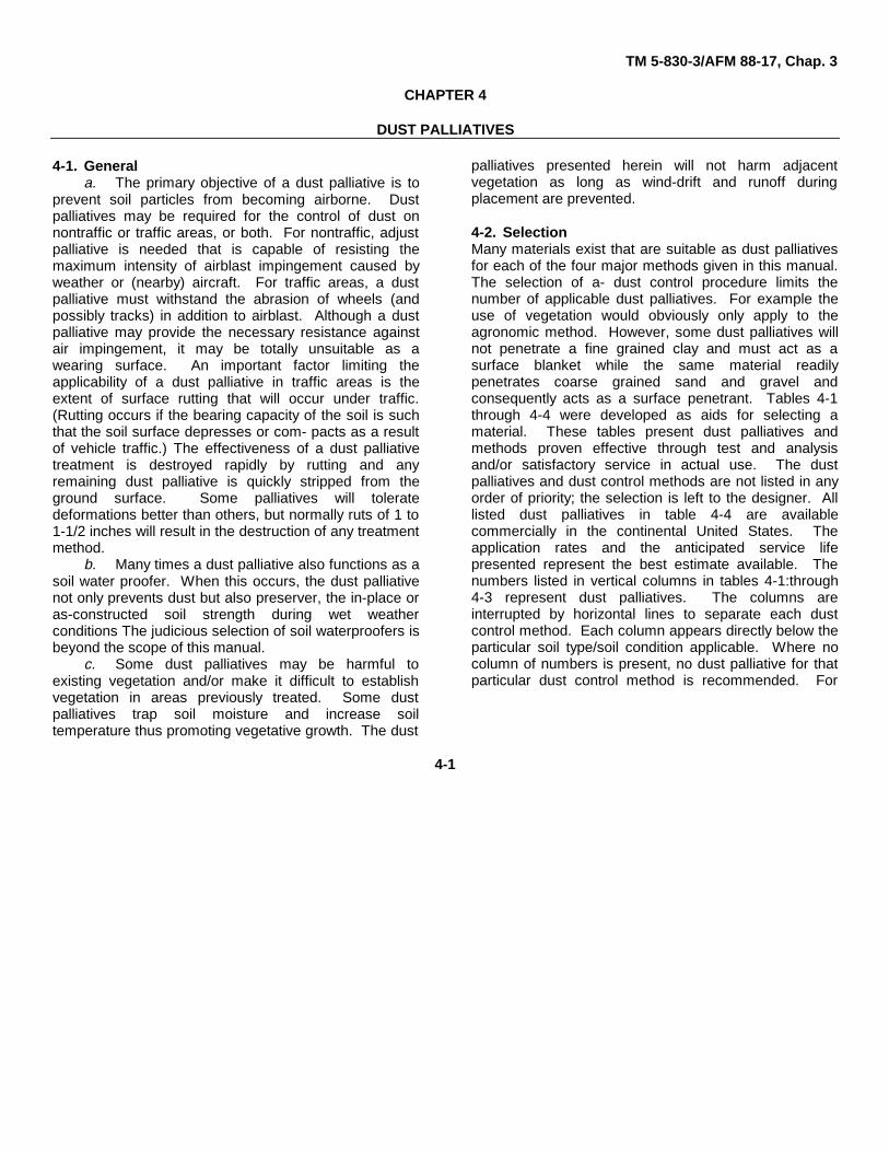
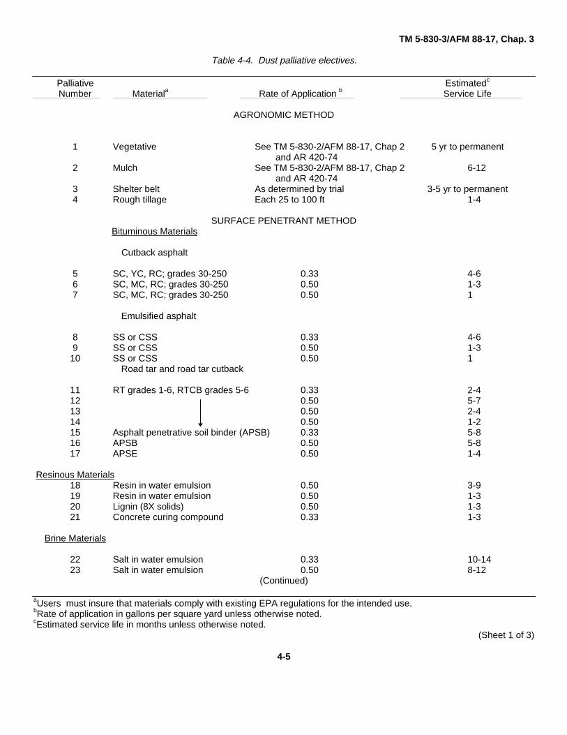
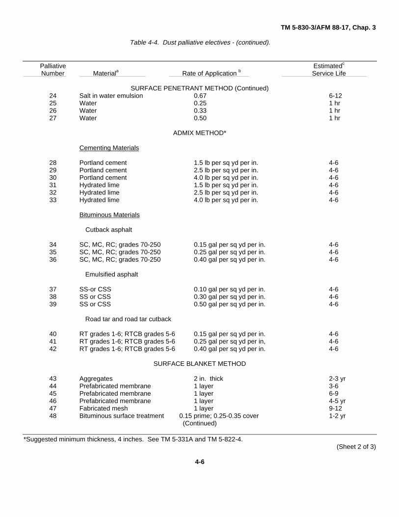
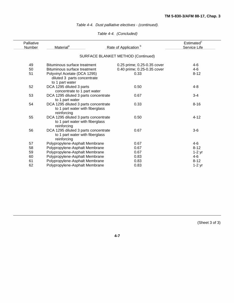
4-2. SelectionMany materials exist that are suitable as dust palliativesfor each of the four major methods given in this manual.The selection of a- dust control procedure limits thenumber of applicable dust palliatives. For example theuse of vegetation would obviously only apply to theagronomic method. However, some dust palliatives willnot penetrate a fine grained clay and must act as asurface blanket while the same material readilypenetrates coarse grained sand and gravel andconsequently acts as a surface penetrant. Tables 4-1through 4-4 were developed as aids for selecting amaterial. These tables present dust palliatives andmethods proven effective through test and analysisand/or satisfactory service in actual use. The dustpalliatives and dust control methods are not listed in anyorder of priority; the selection is left to the designer. Alllisted dust palliatives in table 4-4 are availablecommercially in the continental United States. Theapplication rates and the anticipated service lifepresented represent the best estimate available. Thenumbers listed in vertical columns in tables 4-1:through4-3 represent dust palliatives. The columns areinterrupted by horizontal lines to separate each dustcontrol method. Each column appears directly below theparticular soil type/soil condition applicable. Where nocolumn of numbers is present, no dust palliative for thatparticular dust control method is recommended. For
4-1
TM 5-830-3/AFM 88-17, Chap. 3
Table 4-1. Dust palliative numbers for dust control in nontraffic area.
NOTE: Numbers refer to palliative numbers listed in table 4-4*Hillside (ref para 2-3) applications for liquid dust palliatives should be reduced by half andthen repeated if necessary to avoid runoff/waste.
example, a dust palliative is not recommended for theagronomic method for a loose, sand soil with no bindernor is a dust palliative recommended for the surfacepenetration of a firm, clay soil (tables 4-1 and 4-2). Alsothe agronomic method of dust control is notrecommended for any traffic area (table 4-3). Thecolumn of numbers representing dust palliativesidentified in numerical order and separated by dustcontrol method in table 4-4. Included in table 4-4 is the
suggested rates of application for each dust palliative;gallon per square yard for liquid spray on applications,gallon per square yard per inch for liquid (or pound persquare yard per inch for powders) admix applications.
4-3. Application rates’The application rates should be considered estimates asstated above. Unfortunately the admix method and
4-2
TM 5-830-3/AFM 88-17, Chap. 3
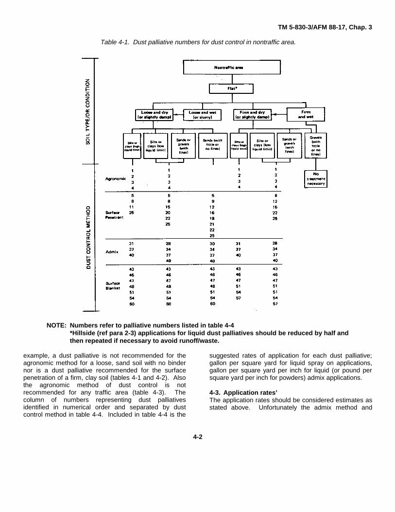
Table 4-2. Dust palliative numbers for dust control in occasional traffic area.
NOTE: Numbers refer to palliative numbers listed in table 4-4*Hillside (ref para 2-3) applications for liquid dust palliatives should be reduced by half andthen repeated if necessary to avoid runoff/waste.
some surface blanket methods represent, a fullcommitment. Should failure occur after selection andplacement, the, only, recourse is to completely; retreat-the failed area which is a lengthy, involved process.However, should failure occur on a section treated witha, liquid, dust palliative, retreatment of the failed area isrelatively simple involving only a distributor and operator.A second application is encouraged as soon as it isdetermined that the initial application rate is notachieving the desired results.
4-4. PlacementNo treatment- is suggested for areas containing largedense vegetation and/or large debris. Loose soil in a wetor slurry condition and firm soil that is wet should not betreated (dust problems should not exist in any of-theseareas). However, if- these areas are known dustproducers when dry, they should be dried or conditionedand then treated.4-5. DilutionSeveral dilution ratios are mentioned for some liquid dustpalliatives. The ratios are presented as volume of
4-3
TM 5-830-3/AFM 88-17, Chap. 3
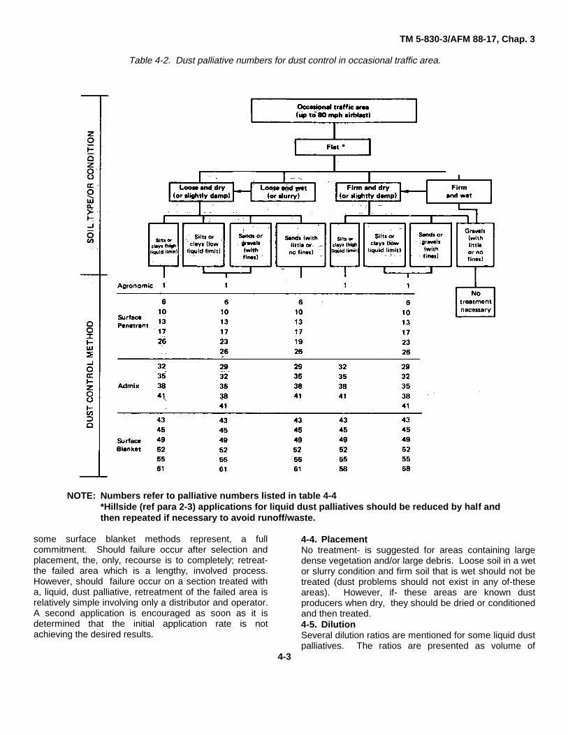
Table 4-3. Dust palliative numbers for dust control in traffic area.
NOTE: Numbers refer to palliative numbers listed in table 4-4.* Hillside (ref para 2-3) applications for liquid dust palliatives should be reduced by halfand then repeated if necessary to avoid runoff/waste.** Upgrade to a firm condition.
concentrate to volume of water and should be viewed asa necessary procedure before a particular liquid can besprayed. The water is a necessary vehicle to get thedust palliative on the ground. The stated application rateis for the dust palliative (only). When high dilution ratiosare required to spray adjust palliative, extra care shouldbe taken to prevent the mixture flowing into adjacentareas where, treatment may be unnecessary and/or intodrainage ditches. Two or more applications may benecessary to achieve the desired application rate.Considerable time can be saved by first determining theminimum dilution that permits a dust palliative to besprayed.
4-6. Prewet
All liquid dust palliatives present a better finished productwhen they are sprayed over an area that has beenprewet with water. The actual amount of prewet watervaries but usually ranges from 0.03 to 0.15 gallons persquare yard. The prewet water should not-be allowed topond on the surface and all exposed soil should becompletely dampened. The performance of brinematerials is enhanced by increasing the amount ofprewet water two to three times the usualrecommendation. However the water should not beallowed to pond, and the fine sized particles should notbe washed away.
4-4
TM 5-830-3/AFM 88-17, Chap. 3
Table 4-4. Dust palliative electives.
Palliative Estimatedc
Number Materiala Rate of Application b Service Life
AGRONOMIC METHOD
1 Vegetative See TM 5-830-2/AFM 88-17, Chap 2 5 yr to permanentand AR 420-74
2 Mulch See TM 5-830-2/AFM 88-17, Chap 2 6-12and AR 420-74
3 Shelter belt As determined by trial 3-5 yr to permanent4 Rough tillage Each 25 to 100 ft 1-4
SURFACE PENETRANT METHODBituminous Materials
Cutback asphalt
5 SC, YC, RC; grades 30-250 0.33 4-66 SC, MC, RC; grades 30-250 0.50 1-37 SC, MC, RC; grades 30-250 0.50 1
Emulsified asphalt
8 SS or CSS 0.33 4-69 SS or CSS 0.50 1-310 SS or CSS 0.50 1
Road tar and road tar cutback
11 RT grades 1-6, RTCB grades 5-6 0.33 2-412 0.50 5-713 0.50 2-414 0.50 1-215 Asphalt penetrative soil binder (APSB) 0.33 5-816 APSB 0.50 5-817 APSE 0.50 1-4
Resinous Materials18 Resin in water emulsion 0.50 3-919 Resin in water emulsion 0.50 1-320 Lignin (8X solids) 0.50 1-321 Concrete curing compound 0.33 1-3
Brine Materials
22 Salt in water emulsion 0.33 10-1423 Salt in water emulsion 0.50 8-12
(Continued)
aUsers must insure that materials comply with existing EPA regulations for the intended use.bRate of application in gallons per square yard unless otherwise noted.cEstimated service life in months unless otherwise noted.
(Sheet 1 of 3)
4-5
TM 5-830-3/AFM 88-17, Chap. 3
Table 4-4. Dust palliative electives - (continued).
Palliative Estimatedc
Number Materiala Rate of Application b Service Life
SURFACE PENETRANT METHOD (Continued)24 Salt in water emulsion 0.67 6-1225 Water 0.25 1 hr26 Water 0.33 1 hr27 Water 0.50 1 hr
ADMIX METHOD*
Cementing Materials
28 Portland cement 1.5 lb per sq yd per in. 4-629 Portland cement 2.5 lb per sq yd per in. 4-630 Portland cement 4.0 lb per sq yd per in. 4-631 Hydrated lime 1.5 lb per sq yd per in. 4-632 Hydrated lime 2.5 lb per sq yd per in. 4-633 Hydrated lime 4.0 lb per sq yd per in. 4-6
Bituminous Materials
Cutback asphalt
34 SC, MC, RC; grades 70-250 0.15 gal per sq yd per in. 4-635 SC, MC, RC; grades 70-250 0.25 gal per sq yd per in. 4-636 SC, MC, RC; grades 70-250 0.40 gal per sq yd per in. 4-6
Emulsified asphalt
37 SS-or CSS 0.10 gal per sq yd per in. 4-638 SS or CSS 0.30 gal per sq yd per in. 4-639 SS or CSS 0.50 gal per sq yd per in. 4-6
Road tar and road tar cutback
40 RT grades 1-6; RTCB grades 5-6 0.15 gal per sq yd per in. 4-641 RT grades 1-6; RTCB grades 5-6 0.25 gal per sq yd per in, 4-642 RT grades 1-6; RTCB grades 5-6 0.40 gal per sq yd per in. 4-6
SURFACE BLANKET METHOD
43 Aggregates 2 in. thick 2-3 yr44 Prefabricated membrane 1 layer 3-645 Prefabricated membrane 1 layer 6-946 Prefabricated membrane 1 layer 4-5 yr47 Fabricated mesh 1 layer 9-1248 Bituminous surface treatment 0.15 prime; 0.25-0.35 cover 1-2 yr
(Continued)
*Suggested minimum thickness, 4 inches. See TM 5-331A and TM 5-822-4.(Sheet 2 of 3)
4-6
TM 5-830-3/AFM 88-17, Chap. 3
Table 4-4. Dust palliative electives - (continued).
Table 4-4. (Concluded)
Palliative Estimatedc
Number Materiala Rate of Application b Service Life
SURFACE BLANKET METHOD (Continued)
49 Bituminous surface treatment 0.25 prime; 0.25-0.35 cover 4-650 Bituminous surface treatment 0.40 prime; 0.25-0.35 cover 4-651 Polyvinyl Acetate (DCA 1295) 0.33 8-12
diluted 3 parts concentrateto 1 part water
52 DCA 1295 diluted 3 parts 0.50 4-8concentrate to 1 part water
53 DCA 1295 diluted 3 parts concentrate 0.67 3-4to 1 part water
54 DCA 1295 diluted 3 parts concentrate 0.33 8-16to 1 part water with fiberglassreinforcing
55 DCA 1295 diluted 3 parts concentrate 0.50 4-12to 1 part water with fiberglassreinforcing
56 DCA 1295 diluted 3 parts concentrate 0.67 3-6to 1 part water with fiberglassreinforcing
57 Polypropylene-Asphalt Membrane 0.67 4-658 Polypropylene-Asphalt Membrane 0.67 8-1259 Polypropylene-Asphalt Membrane 0.67 1-2 yr60 Polypropylene-Asphalt Membrane 0.83 4-661 Polypropylene-Asphalt Membrane 0.83 8-1262 Polypropylene-Asphalt Membrane 0.83 1-2 yr
(Sheet 3 of 3)
4-7

TM 5-830-3/AFM 88-17, Chap. 3
4-7. Cure
Most liquid dust palliatives require a cure period. DCA1295 dries on the soil surface to form a clear film. Thecure time varies depending on the weather at the time ofplacement but averages around 4 hours. Cure iscomplete when the in-place material becomes dry to thetouch. Brine materials do not require a cure period and
traffic can begin immediately following placement. Somebituminous materials are ready for traffic as soon as thematerial temperature drops to the ambient temperature.Traffic can begin immediately on the resinous materialCoherex; when it dries (in several months) itseffectiveness is lessened considerably.
4-8
TM 5-830-3/AFM 88-17, Chap. 3
CHAPTER 5
ECONOMICS
5-1. GeneralDust control is based on many factors and methods.More than one dust palliative is normally found to besatisfactory for the method selected. Economicconsiderations should determine the dust palliativeselected for use.
5-2. Economic factorsEconomic factors should include, but not limited to, thefollowing items:
-Initial cost of the dust palliative(s) at site.-Equipment and labor costs (by method if
applicable).-Maintenance costs (see paragraph 5-2c).-Material storage costs (if applicable).-Shipping costs, equipment acquisition/modification
costs.-Area preparation (clearing and grubbing should be
expected at all sites).From these factors, the most economical dust palliativecan be determined.
a. Initial cost. The initial cost of the dust palliativeshould not be the governing factor in making theselection. Any suitable dust palliative already on handshould be given every consideration, especially whenplacement equipment is available.
b. Equipment and labor costs.(1) Agronomic method. Costs associated
with this method should closely parallel the local turfseeding or landscape planting operational costs in thearea where dust control is desired. Landscapecontractors or similar firms can provide rough estimatesfor planning purposes.
(2) Surface penetrant and surface blanket.Both of these methods recommend some spray on dustpalliatives which can be placed with a common asphalt
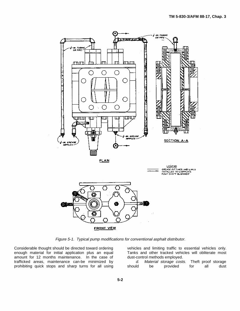
distributor. Bituminous materials lubricate the asphaltdistributor pump when they pass through (this is aninherent feature of bituminous materials). In order tospray other types of dust palliatives (polyvinyl acetate,salts, etc.), the asphalt distributor pump should bealtered for external lubrication of the pump shaftbrushings as shown in figure 5-1. The alteration isestimated to cost less than $400 (1985). Aggregate andmembrane costs are best taken from the supplier(s) nearthe area where dust control is planned. This is especiallytrue for membrane costs. Labor costs associated withthese two methods vary according to the size crewemployed. The minimum size crew for spraying a dustpalliative is one foreman and/or civil engineeringtechnician, one distributor operator, and one laborer. It ispossible to contract the application of dust palliatives.Many membrane suppliers will also contract to placetheir own materials.
(3) Admix method. This method is probablythe most expensive method described. It requiresequipment and man power similar to that associated withcommon road building techniques. The admix methodrequires a rotary tiller mixer, a motor grader, a rubbertired roller, and a water truck. The labor force requires aforeman, operators for the equipment, and two to fourlaborers. The number of laborers is determined by themethod selected for distributing the admix material. Thematerial cost; cement, lime, or bituminous material isbest acquired from the supplier(s) nearest the areawhere dust control is desired. (See TM 5-822-4)
c . Maintenance. No dust-control method or dustpalliative provides a maintenance-free solution. Indeed,frequent maintenance is usually required.
5-1
TM 5-830-3/AFM 88-17, Chap. 3
Figure 5-1. Typical pump modifications for conventional asphalt distributor.
Considerable thought should be directed toward orderingenough material for initial application plus an equalamount for 12 months maintenance. In the case oftrafficked areas, maintenance can-be minimized byprohibiting quick stops and sharp turns for all using
vehicles and limiting traffic to essential vehicles only.Tanks and other tracked vehicles will obliterate mostdust-control methods employed.
d. Material storage costs. Theft proof storageshould be provided for all dust
5-2
TM 5-830-3/AFM 88-17, Chap. 3
palliatives purchased until they can be applied. Some ofthe liquid dust palliatives must be protected from freezingtemperatures. The manufacture should be consultedprior to purchase for storage information/ requirements.Powders such as lime and cement should be stored in adry place with low humidity.
e. Shipping costs. Shipping or transportation costswill be incurred directly or indirectly with all dustpalliatives.
f. Area preparation. Most sites will require somepreparation. As a minimum expect to remove all largerocks 6 in. minimum measure and larger and all large
sticks and stumps. If possible the area to be treatedshould be rolled with a rubber tired roller prior toprewetting to compact the soil and help prolong the dustcontrol treatment.
5-3. Final selection
Some of the economic factors outlined in paragraph 5-2will be difficult to determine with certainty, especiallywhere placement crews have no prior experience withdust palliative placement or, the expected traffic use isnot known. However, by considering these factors thefinal selection of a dust palliative should be easier.
5-3
TM 5-830-3/AFM 88-17, Chap. 3
APPENDIX A
REFERENCES
Government Publications
Department of AgricultureAgriculture Handbook No. 346 Wind Erosion Forces in the
United States and TheirUse in Predicting SoilLoss (April 1968)
Department of DefenseMIL-STD-619B Unified Soil Classification
System for Roads,Airfields. Embankments,and Foundations
Departments of the Army and Air ForceTM 5-330/AFM 86-3, Vol II Planning and Design of
Roads, Airbases, andHeliports in the Theaterof Operations
TM 5-630/AFM 126-2 Ground Maintenance andLand Management
TM 5-822-8/AFM 88-6, Chap. 9 Standard Practice Manualfor Bituminous Materialsin Roads and AirfieldConstruction
TM 5-822-4, Chap. 4 Soil Stabilization forPavements
TM 5-830-2/AFM 88-17, Chap. 2 Planting Turf
Non-Government Publications
American Society for Testing and Materials (ASTM),1916 Race St., Philadelphia, PA 19103.
E 11-81 Wire Cloth Sieves forTesting Purposes
A-1
TM 5-830-3/AFM 88-17, Chap. 3
APPENDIX B
CONTROL OF WINDBORNE SAND
SECTION IDESCRIPTION, DEFINITIONS, FORMATION,
AND-CONTROL OF DUNES
B-1. Introduction
Many factors, including low rainfall, high evaporation,sparse vegetation, and seasonal winds, contribute torock weathering and sand, movement. Methods ofcontrolling sand movement have met with varyingdegrees of success. This appendix summarizes thelatest available information on windborne sand controland lists recommended methods of sand movementstoppage and diversion. Marine and river sandmovement control are not discussed herein.
B-2. Wind, wind direction, crosswind
Wind is defined as any natural movement of air, whetherof high or low velocity, or great or little force. Mostregions have a predominant wind direction-some sectionof the compass from which the wind blows most oftenand with the greatest velocity. Crosswinds are windsdirected at some angle to the predominant winddirection.
B-3. Forms of dunes
A dune is defined as a mound or ridge of windblownmaterial, usually sand, formed in arid regions. Localconditions under which dunes are developed vary widely,and, consequently, there is a broad range in their shapeand size. The shape may, assume almost anyconfiguration, and the size may vary from an insignificantlone sand pebble to mounds higher than 100 feet. Somecoastal dune formations have reached 1,000 feet inheight. The three general types of sand dunes aredescribed below; only the third type requires control.
a. Sand sheets. These sheets occur in a generallyflat, barren area with a predominant wind direction. Theypresent no control problems because the sand does notaccumulate.
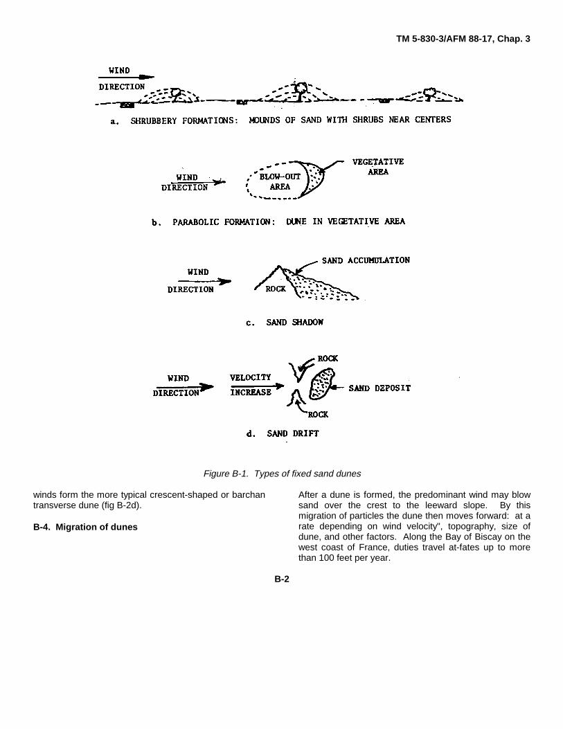
b. Fixed sand dunes. These dunes result from theaccumulation of sand particles adjacent to fixedobstructions such as hills, cliffs, shrubs, and buildings.Fixed sand dunes may range in size from anaccumulation around small shrubbery to sand shadowsmore than 50 feet deep. Because the fixed sand dune isimmobile, it normally does not present a control problem.Figure B-1 -shows the more common types of fixed sanddune formations.
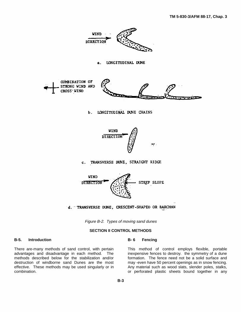
c. Moving sand dunes. This type of sand massexists independent of fixed surface features and maymove from place to place maintaining its initial form.Moving sand dunes are common .in vast areas of sandwith little or no vegetation. The control methodsdescribed below are applicable for this type of dune.With relation to predominant winds, moving sand dunesare classified either as longitudinal or transverse (fig B-2). Longitudinal dunes are distinct ridges elongated inthe direction of the predominant wind (fig B-2a). Acombination of predominant and cross winds willproduce a regular succession of of dunes (fig B-2b).Transverse; dunes are formed by wind of steadydirection blowing across an extensive source of loosesand, such as a sandy beach, and building ridgestransverse to the-wind direction. Low-velocity winds formstraight parallel ridges (fig. B-2c), and stronger
B-1
TM 5-830-3/AFM 88-17, Chap. 3
Figure B-1. Types of fixed sand dunes
winds form the more typical crescent-shaped or barchantransverse dune (fig B-2d).
B-4. Migration of dunes
After a dune is formed, the predominant wind may blowsand over the crest to the leeward slope. By thismigration of particles the dune then moves forward: at arate depending on wind velocity", topography, size ofdune, and other factors. Along the Bay of Biscay on thewest coast of France, duties travel at-fates up to morethan 100 feet per year.
B-2
TM 5-830-3/AFM 88-17, Chap. 3
Figure B-2. Types of moving sand dunes
SECTION II CONTROL METHODS
B-5. Introduction
There are-many methods of sand control, with pertainadvantages and disadvantage in each method. Themethods described below for the stabilization and/ordestruction of windborne sand Dunes are the mosteffective. These methods may be used singularly or incombination.
B- 6 Fencing
This method of control employs flexible, portableinexpensive fences to destroy. the symmetry of a duneformation. The fence need not be a solid surface andmay -even have 50 percent openings as in snow fencing.Any material such as wood slats, slender poles, stalks,or perforated plastic sheets bound together in any
B-3
TM 5-830-3/AFM 88-17, Chap. 3
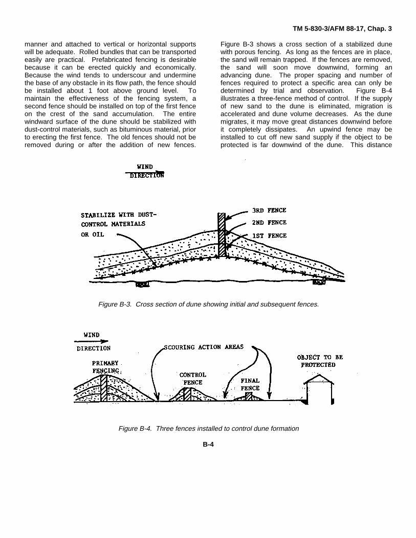
manner and attached to vertical or horizontal supportswill be adequate. Rolled bundles that can be transportedeasily are practical. Prefabricated fencing is desirablebecause it can be erected quickly and economically.Because the wind tends to underscour and underminethe base of any obstacle in its flow path, the fence shouldbe installed about 1 foot above ground level. Tomaintain the effectiveness of the fencing system, asecond fence should be installed on top of the first fenceon the crest of the sand accumulation. The entirewindward surface of the dune should be stabilized withdust-control materials, such as bituminous material, priorto erecting the first fence. The old fences should not beremoved during or after the addition of new fences.
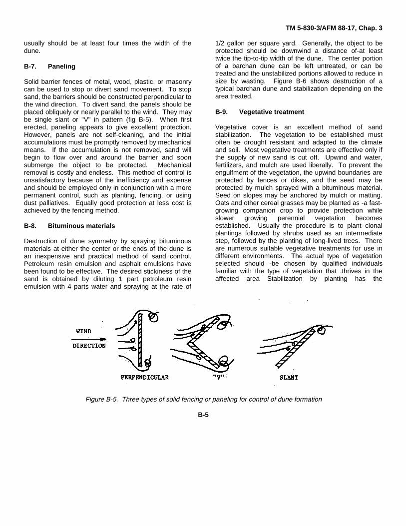
Figure B-3 shows a cross section of a stabilized dunewith porous fencing. As long as the fences are in place,the sand will remain trapped. If the fences are removed,the sand will soon move downwind, forming anadvancing dune. The proper spacing and number offences required to protect a specific area can only bedetermined by trial and observation. Figure B-4illustrates a three-fence method of control. If the supplyof new sand to the dune is eliminated, migration isaccelerated and dune volume decreases. As the dunemigrates, it may move great distances downwind beforeit completely dissipates. An upwind fence may beinstalled to cut off new sand supply if the object to beprotected is far downwind of the dune. This distance
Figure B-3. Cross section of dune showing initial and subsequent fences.
Figure B-4. Three fences installed to control dune formation
B-4
TM 5-830-3/AFM 88-17, Chap. 3
usually should be at least four times the width of thedune.
B-7. Paneling
Solid barrier fences of metal, wood, plastic, or masonrycan be used to stop or divert sand movement. To stopsand, the barriers should be constructed perpendicular tothe wind direction. To divert sand, the panels should beplaced obliquely or nearly parallel to the wind. They maybe single slant or "V" in pattern (fig B-5). When firsterected, paneling appears to give excellent protection.However, panels are not self-cleaning, and the initialaccumulations must be promptly removed by mechanicalmeans. If the accumulation is not removed, sand willbegin to flow over and around the barrier and soonsubmerge the object to be protected. Mechanicalremoval is costly and endless. This method of control isunsatisfactory because of the inefficiency and expenseand should be employed only in conjunction with a morepermanent control, such as planting, fencing, or usingdust palliatives. Equally good protection at less cost isachieved by the fencing method.
B-8. Bituminous materials
Destruction of dune symmetry by spraying bituminousmaterials at either the center or the ends of the dune isan inexpensive and practical method of sand control.Petroleum resin emulsion and asphalt emulsions havebeen found to be effective. The desired stickiness of thesand is obtained by diluting 1 part petroleum resinemulsion with 4 parts water and spraying at the rate of
1/2 gallon per square yard. Generally, the object to beprotected should be downwind a distance of-at leasttwice the tip-to-tip width of the dune. The center portionof a barchan dune can be left untreated, or can betreated and the unstabilized portions allowed to reduce insize by wasting. Figure B-6 shows destruction of atypical barchan dune and stabilization depending on thearea treated.
B-9. Vegetative treatment
Vegetative cover is an excellent method of sandstabilization. The vegetation to be established mustoften be drought resistant and adapted to the climateand soil. Most vegetative treatments are effective only ifthe supply of new sand is cut off. Upwind and water,fertilizers, and mulch are used liberally. To prevent theengulfment of the vegetation, the upwind boundaries areprotected by fences or dikes, and the seed may beprotected by mulch sprayed with a bituminous material.Seed on slopes may be anchored by mulch or matting.Oats and other cereal grasses may be planted as -a fast-growing companion crop to provide protection whileslower growing perennial vegetation becomesestablished. Usually the procedure is to plant clonalplantings followed by shrubs used as an intermediatestep, followed by the planting of long-lived trees. Thereare numerous suitable vegetative treatments for use indifferent environments. The actual type of vegetationselected should -be chosen by qualified individualsfamiliar with the type of vegetation that .thrives in theaffected area Stabilization by planting has the
Figure B-5. Three types of solid fencing or paneling for control of dune formation
B-5
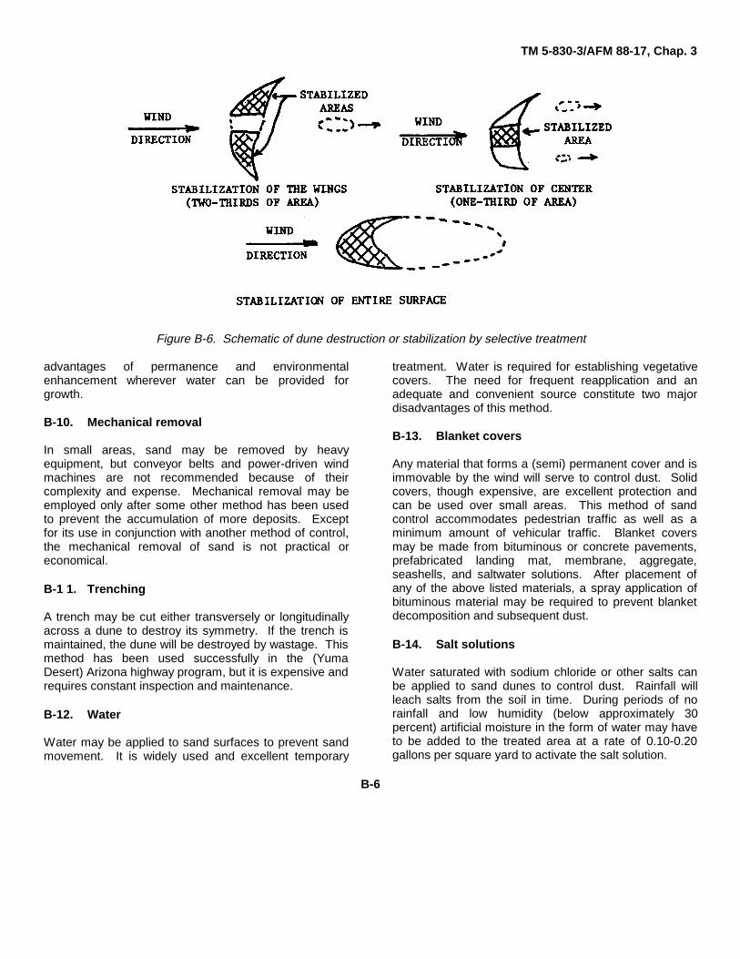
TM 5-830-3/AFM 88-17, Chap. 3
Figure B-6. Schematic of dune destruction or stabilization by selective treatment
advantages of permanence and environmentalenhancement wherever water can be provided forgrowth.
B-10. Mechanical removal
In small areas, sand may be removed by heavyequipment, but conveyor belts and power-driven windmachines are not recommended because of theircomplexity and expense. Mechanical removal may beemployed only after some other method has been usedto prevent the accumulation of more deposits. Exceptfor its use in conjunction with another method of control,the mechanical removal of sand is not practical oreconomical.
B-1 1. Trenching
A trench may be cut either transversely or longitudinallyacross a dune to destroy its symmetry. If the trench ismaintained, the dune will be destroyed by wastage. Thismethod has been used successfully in the (YumaDesert) Arizona highway program, but it is expensive andrequires constant inspection and maintenance.
B-12. Water
Water may be applied to sand surfaces to prevent sandmovement. It is widely used and excellent temporary
treatment. Water is required for establishing vegetativecovers. The need for frequent reapplication and anadequate and convenient source constitute two majordisadvantages of this method.
B-13. Blanket covers
Any material that forms a (semi) permanent cover and isimmovable by the wind will serve to control dust. Solidcovers, though expensive, are excellent protection andcan be used over small areas. This method of sandcontrol accommodates pedestrian traffic as well as aminimum amount of vehicular traffic. Blanket coversmay be made from bituminous or concrete pavements,prefabricated landing mat, membrane, aggregate,seashells, and saltwater solutions. After placement ofany of the above listed materials, a spray application ofbituminous material may be required to prevent blanketdecomposition and subsequent dust.
B-14. Salt solutions
Water saturated with sodium chloride or other salts canbe applied to sand dunes to control dust. Rainfall willleach salts from the soil in time. During periods of norainfall and low humidity (below approximately 30percent) artificial moisture in the form of water may haveto be added to the treated area at a rate of 0.10-0.20gallons per square yard to activate the salt solution.
B-6
TM 5-830-3/AFM 88-17, Chap. 3
BIBLIOGRAPHY
Bagnold, R. A., "The Movement of Desert Sand."Geological Journal, Volume 85, 1935.
Brown, R. L., "Permanent Dune Stabilization withGrasses and Legumes." Journal of Soil WaterConservation, Volume 3, 1948.
Chapman, V. J., "The Stabilization of Sand Dunes byVegetation." Proceedings of Conference on Biologyand Civil Engineering, Institute of Civil Engineers,London, 1949.
Culpepper, M. M. and Wilvert, W. A., "Engineer DesignTests of Dust-Control Materials and EmplacementEquipment." Miscellaneous Paper No. S-72-14. USArmy Engineer Waterways Experiment Station,Vicksburg, Mississippi, June 1972.
Free, E. E., "The Movement of Soil : Material by theWind." US Government Printing Office, Washington,DC, 1911.
Hagen, L., -"Fixation of Sand Dunes." US Army Corps ofEngineers, Professional Memoirs, Volume 8, No. 41,1916.
Headquarters, Department of Army, "Dust Control."Pamphlet 525-5, Washington, DC, February 1969.
Hitchcock, "Controlling Sand Dunes in the United States."National Geological Magazine, Volume XV, 1904.
Kerr, R. C. and Negra, J. O., "Analysis of Eolian SandControl." Arabian American Oil Company, New York,August 1957.
Kozan, G. R., "Stabilization of Shifting Sand."Miscellaneous Paper No. 4968, US Army EngineerWaterways Experiment Station, Vicksburg,Mississippi, March 1968.
Kozan, G. R. and Pimental, R. A., "Guide Manual forSelection and Use of Dust Palliatives and SoilWaterproofers in the Theater of Operations."Miscellaneous Paper No. 4-756, US Army EngineerWaterways Experiment Station, Vicksburg,Mississippi, November 1965.
Kroodsma, R. F., "Permanent Fixation of Sand Dunes inMichigan. "Journal of Forestry, Volume 35, No. 4,April 1937.
Lehotsky, K., "Sand Dune Fixation in Michigan." Journalof Forestry, Volume 39, December 1941.
Lowdermilk, W. C., "Les Lanes, Where Over ThreeQuarters of A Century France Has Transformed VastMobile Sand Dunes and Waste Marshland into RichPine Producing Area" American Forests, Volume 50,August 1944.
Melton, F. A., "A Tentative Classification of Sand Dunes,and Its Application to Dune History in the SouthernGreat Plains." Journal of Geology, Volume 48, 1940.
Oglesby, C. H., and Altenhofen, M. J., "Economics ofDesign Standards for Low-Volume Rural Roads,"National Cooperative Highway Research Program,Report63, Highway Research Record, 1969.
Oldham, J. C., "Section 32 Program, StreambankErosion Control, Evaluation and Demonstration, WorkUnit 4 Research on Soil Stability and Identification ofCauses of Streambank Erosion; Investigation Report1, Evaluation of Spray-On Stabilizers for BankProtection." US Army Engineer WaterwaysExperiment Station, Vicksburg, Mississippi, February1979.
Peters, J. and Sciandrone, J., "Stabilization of SandDunes at Vandenberg Air Force Base." Proceedings,American Society of Civil Engineering, SM4, July1964.
Poe, E., "Lashing Down the Dunes." US Department ofAgriculture, Soil Conservation Service, Washington,DC; July 1945.
Smith, O. W. et al., "Stabilization of Sand Dunes in thePacific Northwest." Bibliography, WashingtonAgriculture Experiment Bulletin, Volume 492, 1947.
BIBLIO-1
TM 5-830-3/AFM 88-17, Chap. 3
Steele, T. A., "Grass and Associated Vegetation toReclaim Oregon’s Coastal Sand Dunes." USDepartment of Agriculture, Soil Conservation Service,Washington, DC, August 1940.
Styron, C. R, "Erosion Control at the ARES Facility,Kirtland Air Force Base, New Mexico." MiscellaneousPaper No. S-72-27, US Army Engineer WaterwaysExperiment Station, Vicksburg, Mississippi, June1972.
Styron, C. R. and Eaves, R. C., "Investigation of Dust-Control Materials." Miscellaneous Paper No. S-73-70,US Army Engineer Waterways Experiment Station,Vicksburg, Mississippi, December 1973.
Styron, C. R. and Spivey, A. C., "MX Road DesignCriteria Studies; Report 2, Investigation of aProprietary Material for Dust Control." TechnicalReport No. GL-82-11, US Army Engineer WaterwaysExperiment Station, Vicksburg, Mississippi,September 1982.
Suter, J., "Sand Road Construction" (Yuma Desert,Arizona-California).
Standard Oil Company of California, San Francisco,California, October 1943.
US Army Corps of Engineers, Beach Erosion Board,"Dune Formation and Stabilization by Vegetation andPlantings." Technical Memorandum No. 101, FortBelvoir, Virginia, October 1957.
US Army Corps of Engineers, Beach Erosion Board,"Shore Protection Planning and Design." TechnicalReport No. 4, Fort Belvoir, Virginia, 1954.
US Army Engineer Waterways Experiment Station,"Dustproofing and Waterproofing of Soils; Report 1,Field and Laboratory Investigations of SelectedMaterials." Technical Report No. 3-530, Vicksburg,Mississippi, December 1959.
US Army Engineer Waterways Experiment Station,"Dustproofing and Waterproofing of Soils; Report 2,Laboratory Studies of Soil Waterproofing Materials."Technical Report No. 3-530, Vicksburg, Mississippi,July 1963.
US Army Engineer Waterways Experiment Station,"Review of Materials and Methods for Dustproofingand Waterproofing Soils." Miscellaneous Paper No. 3-176, Vicksburg, Mississippi, July 1956.
US Army Engineer Waterways Experiment Station, "SoilStabilization Requirements for Military Roads andAirfields in the Theater of Operations." MiscellaneousPaper No. 3-605, Vicksburg, Mississippi, October1963.
US Department of Agriculture, "Mulches for Wind andWater Erosion Control." Agricultural Research Service41-84, Washington, DC, July 1963.
Whitfield, C. J. and Brown, R. L, "Grasses that FixSand Dunes." US Agriculture Yearbook, 1948.
* U.S. GOVERN PRINTING OFFICE: 1993 342-421 (80127)
BIBLIO-2
The proponent agency of this publication is the office of the Chief ofEngineers, United State Army. Users are invited to send commentsand suggested improvements on DA Form 2028 (RecommendedChanges to Publications and Blank Forms) direct to HQDA(DAENECE-G). WASH DC 20314-1000
By Order of the Secretaries of the Army and the Air Force:
CARL E. VUONOGeneral, United States Army
Chief of Staff
Official:
R. L. DILWORTHBrigadier General, United States Army
The Adjutant General
LARRY D. WELCH, General, USAFChief of Staff
OFFICIALWILLIAM O. NATION, COLONEL, USAFDirector of Information Management
and Administration
Distribution:
Army: To be distributed in accordance with DA Form 12-34B, Requirements for Drainage and Erosion ControlStructures.
Air Force: F
PIN: 025965-000


