

Tmax. T GenerationLow voltage molded casecircuit breakers up to 1200 AUL 489 and CSA C22.2 Standard
Technical catalog
1
2
3
4
5
6
Main characteristics
The ranges
Accessories
Characteristic curves and technical information
Wiring diagrams
Overall dimensions
1SXU210023D0201

T GENERATMAX. ADAPTABILITY AND VERSATILITY.
Tmax is freedom. Freedom now reaching up to 1200 A with
the new Tmax T7 circuit breaker. There's a boundless and
highly diversified world of differing types of installations,
requirements, needs and problems from 15 to 1200 A. With
the T Generation everything becomes simple and rational
– eight sizes to find the solutions you're looking for.
BE FREE TO SIZE ANY TYPE OF INSTALLATION IN AN IDEAL WAY AT ALL TIMES. Thanks to the eight sizes and a complete series of magnetic
only, thermal magnetic and electronic trip units. Also a
wide range of accessories are available together with the
possibility of selecting dedicated families for all market
applications, even the most specific and advanced.
BE FREE TO INSTALL ALL SIZES WITHOUT DIFFICULTY. T Generation is undeniably the family of molded case
circuit breakers with the best performance/size ratio
available on the market.

ATION
This means there is more space there is for cabling and
simpler installation. There is also a reduction in the
dimensions of the switchboard.
BE FREE TO RIDE THE MOST ADVANCED TECHNOLOGY. It is thanks to this technology that T Generation now
offers performance levels that were previously out of the
question in circuit breakers with these dimensions. There
are also some exclusive technical solutions which only ABB
can offer you, such as the brand new UL 489 supplement
SE electronic trip units designed for the new Tmax T7 or
the new rapid accessory fitting system.
FREEDOM FOR TOTALLY SAFE SELECTION. The safety of knowing that behind Tmax there is ABB's
strong and constant commitment to the search for excel-
lence at the base of each product and service. ABB quality.

TMAX T1, T2, Ts3 AND T3. ALL SOLUTIONS PERFECTLY COORDINATED, UP TO 225 A.
Tmax T1, T2, Ts3 and T3 – the four “little ones” of the Tmax family – were thought up from the beginning to work together. You can select functions and performances which until now could not be found in circuit breakers with these dimensions. Perfect up to 225 A.There are many characteristics common to the T1, T2 and T3 frames. The single depth 2.76" (70 mm) of the three frames makes installation truly simpler. The new arcing chambers are produced with a gasifying material and an innovative construc-tion system allows the arc extinction time to be reduced.All three sizes are fitted with standard adjustment of the thermal threshold and have new three-pole and four-poles designed and constructed to optimize space in the switchboard and simplify coupling with the circuit breaker.
Tmax T1, T2 and T3 have a completely standardized range of accessories.
TMAX T1. THE LITTLE ONE THAT'S REALLY BIG.Thanks to its extremely compact dimensions, Tmax T1 is a unique circuit breaker in its category. Compared to any other

circuit breaker with the same performance (100 A – up to 50 kA at 240 VAC), the overall dimensions of the apparatus are notably smaller. TMAX T2. INTELLIGENCE AND HIGH PERFORMANCE IN THE PALM OF YOUR HAND.Tmax T2 is the only 100 A circuit breaker available with such high per-formances in such compact overall dimensions. A breaking capacity of 150 kA at 240 VAC can be achieved. Tmax T2 can also be fitted with a latest generation electronic trip unit.
TMAX T3. 225 A IN A DEPTH OF 2.76" (70 MM) FOR THE FIRST TIME.Tmax T3 is the first circuit breaker which carries 225 A in considerably smaller overall dimensions compared to any other similar device – a large step forward for this type of breaker.
TMAX Ts3ABB Tmax Ts3 circuit breaker, in the 150 A frame, can be used at 600 VAC providing excellent interrupting rating performance. The possibility of having circuit breakers certified for use at this voltage allows perfect standardization of the apparatus both on the US and the Canadian market, where 600 V is most widely used.

TMAX T4, T5 AND T6. BE FREE TO CHOOSE UP TO 800 A.
Tmax T4, T5 and T6 are the molded case circuit breakers
with the best performance/size ratio on the market.
The possibilities are practically unlimited, thanks to their
dedicated and specific ranges, advanced electronics, as well
as a complete and standardized range of accessories.
The top quality materials and innovative construction
techniques used by ABB mean Tmax circuit breakers can
guarantee truly exceptional performance. For example,
T4 and T5 have an interrupting capacity up to 150 kA at
480 VAC.

4.07 in
The series of electronic trip units, equipped with latest
generation technology, offers solutions exclusive to ABB.
T4, T5 and T6 have the same depth, simplifying their use
in switchboards, and also have a complete, standardized
and unified range of accessories, simplifying selection,
making them more flexible and reducing stock item count.

TMAX T7. FREEDOM TO THE NTH DEGREE.
Additionally, cabling is facilitated by the reduced height.
The new rapid accessory wiring system is great news. There
are no loose wires inside the circuit breaker. Connection to
the external circuit is rapid, simple and safe and no screws
for terminating the external power supply cables are needed.
The new cable interlock provides notable benefits in terms
of flexible applications. By using this accessory it is possi-
ble to interlock two circuit breakers in any position and to
interlock a T7 with an Emax power circuit breaker as well.
The new Tmax T7, available up to 1200 A either with
a manual operating mechanism or motor operator, was
conceived with a revolutionary design for circuit breakers
of this type: advanced electronics, exceptional performance
and new installation and accessory solutions.
Tmax T7's flexibility is absolutely exceptional: it can be
installed both vertically and horizontally (in both fixed
and draw out versions) with all types of terminals and a
new, faster and safer racking-out system for moving parts.

Special attention has been paid to the electronics and the
results are the PR231, PR232, PR331 and PR332 new
interchangeable electronic trip units, with modules and
rating-plugs which can be replaced by the customer.
The PR231 and PR232 trip units, with dip-switches for
setting the protection thresholds, offer LEDs to signal
tripping for each protection function: so the reason for
circuit breaker tripping can always be easily found.
The PR332 is decidedly ahead of its time fitted with a
large graphic display, it allows all the information needed
to be displayed simply and clearly. It also offers advanced
protection functions. For example, the exclusive data
logger function allows all the events and values before
the fault to be recorded for later analysis.


1
1/1
Main characteristics
IndexOverview of the Tmax family ..................................................................................................... 1/2
General ........................................................................................................................................ 1/4
Construction characteristics
Distinguishing features of the series ............................................................................................. 1/6
1SXU210023D0201

1
1/2
Overview of the Tmax family
MCCBType Tmax T1 1p Tmax T1 Tmax T2 Tmax T3 Tmax Ts3Frame size [A] 100 100 100 225 150Number of poles [No.] 1 3-4 3(6)-4 3-4 2-3-4Rated voltage AC (50-60 Hz) [V] 347 600Y/347 480 600Y/347 600
DC [V] 500 500 600Interrupting ratings B N S H N S N H L
240 V AC [kA rms] 50(2) 65 150 50 65 65 100 150277 V AC [kA rms] 18(1)
347 V AC [kA rms] 14(1)
480 V AC [kA rms] 22(2) 35 65 25 35 25 50 85(5)
600Y/347 V AC [kA rms] 10 10 10600 V AC [kA rms] 14 14 25250 V DC (2 poles in series) [kA rms] 25 25 35500 V DC (3 poles in series) [kA rms] 25 25 35500 V DC (2 poles in series) [kA rms] 35 50 65600 V DC (3 poles in series) [kA rms] 20 35 50
Trip units TMF ■ ■ ■ ■ ■
TMD/TMAMA ■ ■ ■
ElectronicPR221DS ■
PR222DS/PPR222DS/PD-APR231/PPR232/PPR331/PPR332/P
Dimensions H [in/mm] 5.12/130 5.12/130 5.12/130 5.9/150 6.7/170W 3p [in/mm] 1/25.4 3/76 3.54/90 4.13/105 4.13/105D [in/mm] 2.76/70 2.76/70 2.76/70 2.76/70 4.07/103.5
Mechanical life [No. operations] 25000 25000 25000 25000 25000
(1) In 15 A = 10 kA @ 277 V AC - 10 kA @ 347 V AC(2) In 15 A = 35 kA @ 240 V AC - 14 kA @ 480Y/277 V AC
(3) T5 600 with electronic trip units only and in three pole version(4) 2p T4250 and T5400 available only in N interrupting rating(5) In from 15 A up to 30 A = 65 kA @ 480 V AC
(6) T2H 100 3p, T4H 250 3p, T4V 250 3p, T5H 400 3p, T5V 400 3p are defi ned “current limiting”. See the current limiting chapter
MCSType Tmax T1N-D Tmax T3S-D Tmax T3S-DRating [A] 100 150 225Poles [No.] 3-4 3-4 3-4Magnetic override [A] 1000 1500 2250Rated Voltage AC (50-60 Hz) [V] 600Y/347 600Y/347 600Y/347
DC [V] 500 500 500
MCPType Tmax T2 Tmax T3 Tmax Ts3Frame size 100 225 150-225Poles 3 3 3Ratings 20…100 100…200 3…25 50…150 175…200Icu S H S L L L
240 V AC [kA rms] 65 150 65 50 150 150480 V AC [kA rms] 35 65 35 25 85 65600Y/347 V AC [kA rms] 10600 V AC [kA rms] 10 25500 V DC [kA rms] 35 65(1) 65 50600 V DC [kA rms] 50 50
Trip unit Adjustable magnetic only (6…12xIn) ■ ■ ■
Adjustable magnetic only (4…12xIn) ■ ■ ■
PR221DS-IPR231/P-IPR211/P-I
(1) Only for 25A rating
1SXU210023D0201

1
1/3
Tmax Ts3 Tmax T4 Tmax T5 Tmax T6 Tmax T7225 250 400-600(3) 800 1000-1200
2-3-4 2(4)-3(6)-4 2(4)-3(6)-4 3-4 3-4480 600 600 600 600500 600 600 600
N H L N S H L V N S H L V N S H L S H L65 100 150 65 100 150 200 200 65 100 150 200 200 65 100 200 200 65 100 150
25 50 65 25 35 65 100 150 25 35 65 100 150 35 50 65 100 50 65 100
18 25 35 65 100 18 25 35 65 100 20 25 35 42 25 50 65
20 35 50 25 35 50 65 100 25 35 50 65 100 35 35 50 6516 25 35 50 65 16 25 35 50 65 20 20 35 50
■ ■
■ ■ ■
■
■ ■ ■
■ ■ ■
■ ■ ■
■
■
■
■
6.7/170 8.07/205 8.07/205 10.55/268 10.55/2684.13/105 4.13/105 5.51/140 8.26/210 8.26/210
4.07/103.5 4.07/103.5 4.07/103.5 4.07/103.5 6.06/154(toggle)-7/178(motor)25000 20000 20000 20000 10000
Tmax Ts3H-D 150 Tmax Ts3H-D 225 Tmax T4N-S-H-L-V-D Tmax T5N-S-H-L-V-D Tmax T6H-D Tmax T7H-D150 225 250 400-600 800 12003-4 3-4 3-4 3-4 3-4 3-4
1500 2250 3000 5000 10000 20000600 480 600 600 600 600600 500 600 600 600 –
Tmax T4 Tmax T5 Tmax T6 Tmax T7250 400-600 800 1000-12003 3 3 3
100-150-250 300-400-600 600-800 1000-1200N S H L N S H L N S H L S H L65 100 150 200 65 100 150 200 65 100 200 200 65 100 15025 35 65 100 25 35 65 100 35 50 65 100 50 65 100
18 25 35 65 18 25 35 65 20 25 35 42 25 50 65
■ ■ ■ ■ ■ ■ ■ ■ ■ ■ ■ ■
■ ■ ■
1SXU210023D0201

1
1/4
22
21
23 20
14
15
16
17
6
5
8
9
11
12
10
13
2
7
3
7
14
18
19
Construction characteristicsModularity of the series
1SXU210023D0201

1
1/5
1SD
C21
0A16
F000
1
24
25
26
27
28
Starting from the fi xed version circuit breaker, all the other versions used for various requirements are obtained by means of mounting conversion kits.The following are available:– kit for converting a fi xed circuit breaker into the moving part of a plug-in
and draw out one – circuit breaker cradles for plug-in and draw out circuit breakers– conversion kit for the connection terminals.
Various accessories are also available:1. Frame2. Trip units3. Front plate4. Auxiliary contacts - AUX and AUX-E5. Undervoltage release - UVR6. Shunt trip - SOR and P-SOR7. Terminal covers8. Front for lever operating mechanism - FLD9. Direct rotary handle - RHD10. Stored energy motor operator - MOE11. Key lock - KLF12. Early auxiliary contact - AUE13. Transmitted rotary handle - RHE14. Front terminal for copper cable - FC Cu15. Front extended terminal - EF16. Multi-cable terminal - MC17. Front terminal for copper-aluminium - FC CuAl18. Front extended spread terminal - ES19. Rear orientated terminal - R20. Conversion kit for plug-in/draw out versions21. Cradle guide in the draw out version22. Cradle - FP23. Auxiliary position contact - AUP24. Phase separators25. PR010T26. TT127. Racking out crank handle28. Residual current release.
1SXU210023D0201

1
1/6
1SD
C21
0A18
F000
11S
DC
210A
20F0
001
1SD
C21
0A17
F000
1
1SD
C21
0A19
F000
1
Double insulationTmax has double insulation between the live power parts (excluding the terminals) and the front of the apparatus where the operator works during normal operation of the device. The placement of each elec-trical accessory is completely segregated from the power circuit, preventing any risk of contact with live parts and the operating mechanism is completely insulated from the powered circuits.Furthermore, the circuit breaker has oversized insulation, both between the live internal parts and in the area of the connection terminals. In fact, the distances exceed those required by the IEC Standards and comply with the UL 489 Standard.
Positive operationThe operating lever always indicates the precise position of the moving contacts of the circuit breaker, thereby providing safe and reliable signals, in compliance with IEC 60073 and IEC 60417-2 Standard (I = Closed; O = Open; yellow-green line = Open due to protection trip). The circuit breaker operating mechanism is trip free regardless of the pressure on the lever. Protection tripping automatically opens the moving contacts: to close them again the operating mechanism must be reset by pushing the operating lever from the tripped position into the reset position.
Isolation behaviourIn the open position, the circuit breaker complies with the IEC 60947-2 Standard. The oversized insulation distances guarantee there are no leakage currents and dielectric resistance to any overvoltages between input and output.
Degrees of protectionThe table indicates the degrees of protection guaranteed by the Tmax circuit breakers according to the IEC 60529 Standard:
The cradles are always preset with IP20 degree of protection. IP54 degree of protection can be obtained with the circuit breaker installed in a switchboard fi tted with a rotary handle operating mechanism trans-mitted on the compartment door and special kit (RHE – IP54).
With front
Without front (2)
Without terminal covers
With high terminal covers
With low terminal covers
With IP40 protection kit on the front
A IP 40(3) IP 20 – – – – B(4) IP 20 IP 20 IP 20 IP 40 IP 40 IP 40
C – – – IP 40(1) IP 30(1) –(1) After correct installation (3) Also for front for lever operating mechanism and direct rotary handle(2) During installation of the electrical accessories (4) Only for T1...T6
Construction characteristicsDistinguishing features of the series
1SXU210023D0201

1
1/7
1SD
C21
0A21
F000
1
Operating temperatureThe Tmax circuit breakers can be used in ambient conditions where air temperature varies between -13 °F and +158 °F (-25 °C and +70 °C), and stored in environments with temperatures between -40 °F and +158 °F (-40 °C and +70 °C).The circuit breakers fi tted with thermal magnetic trip units have their thermal element set for a reference temperature of 104 °F (+40 °C). For temperatures other than 104 °F (+40 °C), with the same setting, there is a devation table as shown beginning on page 4/50.The electronic trip units do not undergo any variations in performance as the temperature varies except in cases of temperatures exceeding 104 °F (+40 °C). Then maximum setting for protection against overloads L must be reduced, as indicated in the derating graph beginning on page 4/37, to take into account the heating phenomena which occur in the current carrying copper parts of the circuit breaker.For temperatures above 158 °F (+70 °C) the circuit breaker performances are not guaranteed. To ensure service continuity of the installations, the temperature must be kept within acceptable levels for opera-tion of the various devices and the circuit breakers by using forced ventilation in the switchboards or in their installation room.
AltitudeUp to an altitude of 6600 ft the Tmax circuit breakers do not undergo any changes in their rated perfor-mance. Above this altitude, the atmospheric properties are altered in terms of composition, dielectric resistance, cooling capacity and pressure, requiring the circuit breaker performance to be derated per the table below.
Altitude [ft] 6600 9900 13200 16500
Rated service voltage, Ue [V~] 600 522 435 348Rated uninterrupted current, Iu %Iu 100 98 93 90
1SXU210023D0201

1
1/8
1SD
C21
0A23
F000
11S
DC
210A
25F0
001
Construction characteristicsDistinguishing features of the series
Electromagnetic compatibilityProtection operation is guaranteed by using the electronic trip units and the electronic residual current releases in the presence of interference caused by electronic devices, atmospheric disturbances or elec-trical discharges. No interference with other electronic devices near the place of installation is generated either. This is in compliance with the IEC 60947-2 Appendix B + Appendix F Standards and European Directive No. 89/336 regarding EMC - electromagnetic compatibility.
TropicalizationCircuit breakers and accessories in the Tmax series are tested in compliance with the IEC 60068-2-30 Standard, carrying out 2 cycles at 131 °F (55 °C) with the “variant 1” method (clause 6.3.3). The suitability of the Tmax series for use under the most severe environmental conditions is therefore ensured with the hot-humid climate defi ned in the climatograph 8 of the IEC 60721-2-1 Standards thanks to:– moulded insulating cases made of synthetic resins reinforced with glass fi bres;– anti-corrosion treatment of the main metallic parts;– Fe/Zn 12 zinc-plating (ISO 2081) protected by a conversion layer, free from hexavalent-chromium
(ROHS-compliant), with the same corrosion resistance guaranteed by ISO 4520 class 2c;– application of anti-condensation protection for electronic overcurrent releases and relative accesso-
ries.
Resistance to shock and vibrationThe circuit breakers are unaffected by vibrations generated mechanically or due to electromagnetic ef-fects, in compliance with the IEC 60068-2-6 Standards and the regulations of the major classifi cation organizations(1):– RINA– Det Norske Veritas– Bureau Veritas– Lloyd’s register of shipping– Germanischer Lloyd– ABS– Russian Maritime Register of Shipping.The T1-T5 Tmax circuit breakers are also tested according to the IEC 60068-2-27 Standard to resist shock up to 12g for 11 ms. Please ask ABB for details about higher performance in terms of resistance to shock.
(1) Ask to ABB for Tmax certifi cates of approval.
1SXU210023D0201

1
1/9
1SD
C21
0A40
F000
1 U
L1S
DC
210A
41F0
001
UL
Versions and typesAll the Tmax circuit breakers are available in fi xed versions, T2, T3, Ts3, T4 and T5 in the plug-in version and Ts3, T4, T5, T6 and T7 also in the draw out one.All the circuit breakers can be manually operated by the operating lever or the rotary handle (direct or variable depth), and electrically operated. For electric operation different solutions are available:– The solenoid operator for T1, T2 and T3– The direct action motor operator for Ts3– The stored energy motor operator for T4, T5 and T6– T7 with the stored energy operating mechanism, gear motor for the charging of the closing springs
and shunt opening and closing releases.
InstallationTmax circuit breakers can be installed in switchboards mounted in any horizontal, vertical or lying down position on the back plate or on rails, without undergoing any derating. Tmax circuit breakers can be easily installed in all types of switchboards, thanks to the possibility of being reversefed.Apart from fi xing on the base plate, T1, T2 and T3 can also be installed on DIN 50022 rails and Ts3 can also be installed on DIN 50023 rails thanks to the special fi xing brackets.Furthermore, the depth of 2.76 inches (70 mm) takes Tmax T3 to the same depth as the two smaller sizes, making assembly of circuit breakers up to 225 A in standard switchboards even simpler. In fact, it is possible to prepare standardized support structures, facilitating the design stage and construction of the switchboard interior.
1SXU210023D0201

1
1/10
1SD
C21
0A35
F000
1
Construction characteristicsDistinguishing features of the series
Racking-out with the door closedWith Tmax Ts3, T4, T5, T6 and T7 circuit breakers in the draw out version the circuit breaker can be racked-in and out with the compartment door closed, increasing operator safety and allowing realization of low voltage arc proof switchboards.Racking out can only be carried out with the circuit breaker open (for safety reasons), using a special racking-out crank handle supplied with the conversion kit from fi xed circuit breaker to moving part of draw out circuit breaker.
Range of accessoriesThe completeness and installation rationality of the Tmax series is also achieved thanks to innovative solutions in development of the accessories:– single range of accessories for T1, T2 and T3; one for T4, T5 and T6, and one for T7, characterised
by completeness and simplicity for installation. The Ts3 due to its unique characteristics has its own group of accessories. Harmonization of the accessories allows reduction in stocks and greater service fl exibility, offering increasing advantages for users of the Tmax series;
– new system of rapid assembly for internal electrical accessories of Tmax T7 without cables for the connections to the terminal box;
– same possibility of equipping with terminals, in terms of connection devices (terminals, terminal covers and phase separators), between fi xed circuit breakers and cradles of plug-in circuit breakers for Tmax T2 and T3.
– moreover, Tmax offers a wide choice of IEC rated residual current releases (IEC only): - three-pole and four-pole RC221 and RC222 up to 225 A with T1, T2 and T3; - RC211 and RC212 for Ts3; - RC222, four-pole up to 500 A for T4 and T5; - RC223 (type B) also sensitive to currents with continuous slowly variable components (IEC 60947-2
Annex M), four-pole for T3 and T4, up to 250 A.
1SXU210023D0201

1
1/11
1SD
C21
0A37
F000
1
Compliance with Standards and company Quality SystemThe Tmax circuit breakers and their electrical accessories conform to the UL 489 (Underwriters Laborato-ries Incorporated) and CSA C22.2 No. 5.1 (Canadian Standard Association) North American Standards, and to the international IEC 60947-2 Standards and comply with the EC directive:– “Low Voltage Directives” (LVD) no. 2006/95/CE (replaces 72/23/EEC and subsequent amendments)– “Electromagnetic Compatibility Directive” (EMC) no. 89/336 EEC.Certifi cation of compliance with the above-mentioned product Standards is carried out, in respect of the European EN 45011 Standard, by the Italian certifi cation body ACAE (Association for Certifi cation of Electrical Apparatus), a member of the European LOVAG organization (Low Voltage Agreement Group).The ABB test laboratory is accredited by SINAL (certifi cate no. 062/2002).The ABB Quality System complies with the international ISO 9001 - 2000 Standard (model for quality as-surance in design, development, construction, installation and service) and with the equivalent European EN ISO 9001 and Italian UNI EN ISO 9001 Standards.The independent certifying Body is RINA S.p.A. ABB obtained its fi rst certifi cation with three-year validity in 1990, and has now reached its fourth reconfi rmation.The new Tmax series has a hologram on the front, obtained using special anti-imitation techniques, which guarantees the quality and that the circuit breaker is an original ABB product. Attention to protection of the environment and to health and safety in the work place is another priority commitment for ABB and, as confi rmation of this, the company environmental manage-ment system has been certifi ed by RINA in 1997, in conformity with the international ISO 14001 Standard. This certifi cation has been integrated in 1999 with the Management System for Healt and Safety in the workplace, according to OHSAS 18001 (British Standards), obtaining one of the fi rst certifi cation of integrated management System, QES (Quality, Environment, Safety) issued by RINA. ABB – the fi rst industry in the electromechanical section in Italy to obtain this recognition – thanks to a revision of the production process with an eye to ecology, has been able to reduce the consumption of raw materials and processing waste by 20%.ABB’s commitment to safeguarding the environment is also shown by the Life Cycle Assessments of its products carried out directly by ABB Research and Development in collaboration with the ABB Research Center. Selection of materials, processes and packing materials is made optimizing the true environmental impact of the product, also foreseeing the possibility of its being recycled.
1SXU210023D0201
2
2/1
The ranges
Index
Power distribution circuit breakers
Electrical characteristics ................................................................................................................2/4
General characteristics ...................................................................................................................2/6
Thermal magnetic trip units ............................................................................................................2/8
Electronic trip units .........................................................................................................................2/9
Motor Control Protection circuit breakers: MCP
Electrical characteristics ..............................................................................................................2/34
General characteristics .................................................................................................................2/36
Molded Case Switches: MCS
Electrical characteristics ..............................................................................................................2/40
Current Limiting
Electrical characteristics ..............................................................................................................2/44
1SXU210023D0201


2
2/3
Power distribution circuit breakers
Index
Power distribution circuit breakers
Electrical characteristics ................................................................................................................2/4
General characteristics ...................................................................................................................2/6
Thermal magnetic trip units ............................................................................................................2/8
Electronic trip units .........................................................................................................................2/9
1SXU210023D0201

2
2/4
Power distribution circuit breakersElectrical characteristics
MCCB
Type Tmax T1 1p Tmax T1 Tmax T2 Tmax T3 Tmax Ts3
Frame size [A] 100 100 100 225 150
Number of poles [No.] 1 3-4 3(6)-4 3-4 2-3-4
Rated voltage AC (50-60 Hz) [V] 347 600Y/347 480 600Y/347 600
DC [V] 500 500 600
Interrupting ratings B N S H N S N H L
240 V AC [kA rms] 50(2) 65 150 50 65 65 100 150
277 V AC [kA rms] 18(1)
347 V AC [kA rms] 14(1)
480 V AC [kA rms] 22(2) 35 65 25 35 25 50 85(5)
600Y/347 V AC [kA rms] 10 10 10
600 V AC [kA rms] 14 14 25
250 V DC (2 poles in series) [kA rms] 25 25 35
500 V DC (3 poles in series) [kA rms] 25 25 35
500 V DC (2 poles in series) [kA rms] 35 50 65
600 V DC (3 poles in series) [kA rms] 20 35 50
Versions F F F-P F-P F-P-W
Trip units TMF ■ ■ ■ ■ ■
TMD/TMA
MA ■ ■ ■
Electronic
PR221DS ■
PR222DS/P
PR222DS/PD-A
PR231/P
PR232/P
PR331/P
PR332/P
Dimensions H [in/mm] 5.12/130 5.12/130 5.12/130 5.9/150 6.7/170
W 3p [in/mm] 1/25.4 3/76 3.54/90 4.13/105 4.13/105
D [in/mm] 2.76/70 2.76/70 2.76/70 2.76/70 4.07/103.5
Mechanical life [No. operations] 25000 25000 25000 25000 25000
(1) In 15 A = 10 kA @ 277 V AC - 10 kA @ 347 V AC(2) In 15 A = 35 kA @ 240 V AC - 14 kA @ 480Y/277 V AC(3) T5 600 with electronic trip units only and in three pole version(4) 2p T4250 and T5400 available only in N interrupting rating
(5) In from 15 A up to 30 A = 65 kA @ 480 V AC(6) T2H 100 3p, T4H 250 3p, T4V 250 3p, T5H 400 3p, T5V 400 3p are defi ned current limiting. See the current limiting chapter
F = FixedP = Plug-inW = Draw-out
1SXU210023D0201

2/5
2
Tmax Ts3 Tmax T4 Tmax T5 Tmax T6 Tmax T7
225 250 400-600(3) 800 1000-1200
2-3-4 2(4)-3(6)-4 2(4)-3(6)-4 3-4 3-4
480 600 600 600 600
500 600 600 600
N H L N S H L V N S H L V N S H L S H L
65 100 150 65 100 150 200 200 65 100 150 200 200 65 100 200 200 65 100 150
25 50 65 25 35 65 100 150 25 35 65 100 150 35 50 65 100 50 65 100
18 25 35 65 100 18 25 35 65 100 20 25 35 42 25 50 65
20 35 50 25 35 50 65 100 25 35 50 65 100 35 35 50 65
16 25 35 50 65 16 25 35 50 65 20 20 35 50
F-P-W F-P-W F-P-W F-W F-W
■ ■
■ ■ ■
■
■ ■ ■
■ ■ ■
■ ■ ■
■
■
■
■
6.7/170 8.07/205 8.07/205 10.55/268 10.55/268
4.13/105 4.13/105 5.51/140 8.26/210 8.26/210
4.07/103.5 4.07/103.5 4.07/103.5 4.07/103.5 6.06/154(toggle)-7/178(motor)
25000 20000 20000 20000 10000
1SXU210023D0201

2
2/6
Power distribution circuit breakersGeneral characteristics
(*) For motorization, the T7 circuit breaker with stored energy operating mechanism must be ordered, complete with geared motor for automatic spring charging, opening coil and closing coil.
The series of Tmax molded case circuit breakers − complying with the UL 489 and CSA C22.2 No. 5 Standards − is divided into different basic sizes, with an application range from 15 A to 1200 A and breaking capacities up to 150 kA at 480 VAC.For protection of alternating current networks, the following are available:– T1B 1p, T1, T2, T3, Ts3 and T4 circuit breakers equipped with TMF thermal magnetic trip units with
fi xed thermal and magnetic threshold (I3 = 10 x In);– T4 (up to 50 A) circuit breaker equipped with TMD thermal magnetic trip units with adjustable thermal
threshold (I1 = 0.7…1 x In) and fi xed magnetic threshold (I3 = 10 x In);– T4, T5 and T6 circuit breakers with TMA thermal magnetic trip units with adjustable thermal threshold
(I1 = 0.7…1 x In) and adjustable magnetic threshold (I3 = 5…10 x In);– T2 with PR221DS electronic trip unit;– T4, T5 and T6 with PR221DS, PR222DS/P and PR222DS/PD-A electronic trip units;– the T7 circuit breaker, which completes the Tmax family up to 1200 A, fi tted with PR231/P, PR232/P,
PR331/P and PR332/P electronic trip units. The T7 circuit breaker is available in the two versions: with a manual operating mechanism or a motorized stored energy operating mechanism(*).
The fi eld of application in alternating current of the Tmax series varies from 1 A to 1200 A with voltages up to 600 V. The Tmax T1, T2, T3, Ts3, T4, T5 and T6 circuit breakers equipped with TMF, TMD and TMA thermal magnetic trip units can also be used in direct current plants, with a range of applications from 15 A to 800 A and a minimum operating voltage of 24 V DC, according to the appropriate connec-tion diagrams. The three-pole T2, T3 and Ts3 circuit breakers can also be fi tted with MA adjustable magnetic only trip units, both for applications in alternating current and in direct current, in particular for motor protection (see page 2/33 and following).For all the circuit breakers in the series, fi tted with thermal magnetic and electronic trip units, the single-phase trip current is defi ned (see page 4/26).
InterchangeabilityThe Tmax T4, T5 and T6 circuit breakers can be equipped either with TMF, TMD or TMA thermal magnetic trip units, MA magnetic only trip units or PR221DS, PR222DS/P, PR222DS/PD-A electronic trip units.Similarly, Tmax T7 can also mount the latest generation PR231/P, PR232/P, PR331/P(1) and PR332/P(1) electronic trip units.
Trip unitsCircuit breakers TMF TMD TMAIn [A] 15 20 30 40 50 80 100 125 150 200 250 300 400 600 800T4 250 ■ ■ ■ ■ ■ ■ ■ ■ ■ ■ ■
T5 400 ■ ■
T5 600T6 800 ■ ■
T7 1000T7 1200
■ = Complete circuit breaker already coded▲ = Circuit breaker to be assembled
(1) If ordered loose PR331/P and PR332/P must be completed with the “trip unit adapters” (see page 3/45)
1SXU210023D0201

2/7
2
Range of application of the circuit breakers in alternating current and in direct current
AC Trip unit Range [A]T1 1p 100 TMF 15…100T1 100 TMF 15…100T2 100 TMF 15…100
MA 20…100PR221DS 25…100
T3 225 TMF 60…225MA 100…200
Ts3 150 TMF 15…150MA 3…150
Ts3 225 TMF 175…225MA 175…200
T4 250 TMF 15…250TMD 20TMA 30…50
PR221DS 80…250PR222DS/P-PR222DS/PD-A 100…250
T5 400/600 TMA 300…400PR221DS 300-400-600
PR222DS/P-PR222DS/PD-A 300-400-600T6 800 TMA 600…800
PR221DS 600…800PR222DS/P-PR222DS/PD-A 600…800
T7 1000/1200 PR231/P-PR232/P 400…1200PR331/P-PR332/P 400…1200
DCT1 100 TMF 15…100T2 MA 20…100T3 225 TMF 60…225Ts3 150 TMF 15…150
MA 3…150Ts3 225 TMF 175…225
MA 175…200T4 250 TMD 15…250
TMA 15…250TMF 15…250
T5 400/600 TMA 300-400T6 800 TMA 600…800
MA = magnetic only trip unit with adjustable magnetic thresholds
TMF = thermal magnetic trip unit with fi xe thermal and magnetic thresholds
TMD = thermal magnetic tr ip unit with adjustable thermal and fi xed magnetic thresholds
TMA = thermal magnetic tr ip unit with adjustable thermal and magnetic thresholds
PR22_, PR23_, PR33_ = electronic trip units
Thanks to their simply assembly, the end customer can change the type of trip unit extremely rapidly according to their own requirements and needs. In this case, correct assembly is the customer’s re-sponsibility. Above all, this means into increased fl exibility of use of the circuit breakers with considerable savings in terms of costs thanks to better rationalization of stock management.
PR221DS-PR222DS/P-PR222DS/PD-A(2) PR231/P(3)-PR232/P-PR331/P-PR332/P100 150 250 300 400 600 800 400 600 800 1000 1200■ ■ ■
■ ■
■
■ ■
▲ ▲ ▲ ■
▲ ▲ ▲ ▲ ■
(2) PR223DS, minimum In = 160 A (3) Interchangeability of PR231/P can be requested by means of the dedicated ordering code 1SDA063140R1
1SXU210023D0201

2
2/8
Power distribution circuit breakersThermal magnetic trip units
The Tmax T1 1p, T1, T2, T3, Ts3, T4, T5 and T6 circuit breakers can be fi tted with thermal magnetic trip units and are used in protection of alternating and direct current networks with a range of use from 15 A to 800 A. They allow the protection against overload with a thermal device (with fi xed threshold for T1 1p, T1, T2, T3, Ts3, T4 and adjustable threshold for T4, T5 and T6) realized using the bimetal technique, and protection against short-circuit with a magnetic device (with fi xed threshold for T1, T2, T3, Ts3 and T4 up to 50 A and adjustable threshold for T4, T5 and T6).The four-pole circuit breakers are always supplied with the neutral protected by the trip unit and with protection of the neutral at 100% of the phase settings up to 100 A. For higher settings, the protection of the neutral is at 50% of the phase setting unless the protection of the neutral at 100% of the phase setting is required.
Thermal magnetic trip unitsIn [A] 15 20 25 30 35 40 50 60 70 80 90 100 125 150 175 200 225 250 300 400 600 800
Neutral [A] 15 20 25 30 35 40 50 60 70 80 90 100 125 150 175 200 225 250 300 400 600 800
T1 (I1=In) ■ ■ ■ ■ ■ ■ ■ ■ ■ ■ ■
T2 (I1=In) ■ ■ ■ ■ ■ ■ ■ ■ ■ ■ ■ ■
T3 (I1=In) ■ ■ ■ ■ ■ ■ ■ ■ ■ ■
Ts3 (I1=In) ■ ■ ■ ■ ■ ■ ■ ■ ■ ■ ■ ■ ■ ■ ■ ■ ■
T4 (I1=In) ■ ■
T4 (I1=0.7...1xIn) ■ ■ ■ ■ ■ ■ ■ ■ ■
T5 400 (I1=0.7...1xIn) ■ ■
T6 (I1=0.7...1xIn) ■ ■
T1
I3 [A] 1000 1000 1000 1000 1000 1500 1500 1500 1500 1500 1500
Neutral [A] 1000 1000 1000 1000 1000 1500 1500 1500 1500 1500 1500
T2, T3
I3 [A] 500 500 500 500 500 500 500 600 700 800 900 1000 1250 1500 1750 2000 2250
Neutral [A] 500 500 500 500 500 500 500 600 700 800 900 1000 1250 1500 1750 2000 2250
Ts3
I3 [A] 500 500 500 500 500 500 500 600 700 800 900 1000 1250 1500 1750 2000 2250
Neutral [A] 500 500 500 500 500 500 500 600 700 800 900 1000 1250 1500 1750 2000 2250
T4, T5
I3 [A] 500 500 500 500 500 400800
5001000
6251250
7501500
10002000
12502500
15003000
20004000
30006000
40008000
Neutral [A] 500 500 500 500 500 400800
5001000
6251250
7501500
10002000
12502500
15003000
20004000
30006000
40008000
T6
I3 = 5...10xIn [A] 30006000
40008000
Neutral [A] - 100% 30006000
40008000
Neutral [A] - 50% 15003000
20004000
1SXU210023D0201

2/9
2
Power distribution circuit breakersElectronic trip units
For use in alternating current the Tmax T2, T4, T5, T6 and T7 circuit breakers can be equipped with trip units constructed using electronic technology. This allows protection functions to be obtained which provide high reliability, tripping precision and insensitivity to temperature and to the electromagnetic components.The power supply needed for correct operation is supplied directly by the current sensors of the trip unit, and tripping is always guaranteed, even under single-phase load conditions.
When a protection function trips, the circuit breaker opens by means of the trip coil, which changes the contact AUX-SA (supplied on request, see chapter “Accessories” at page 3/21 and following) to tripping. Mechanical signalling reset takes place with resetting of the circuit breaker.
Current sensors
In [A] 25 60 100 150 250 300 400 600 800 1000 1200
PR221DS T2 ■ ■ ■ ■
T4 ■ ■ ■ ■
T5 ■ ■ ■
T6 ■ ■
PR222DS/P, PR222DS/PD-A
T4 ■ ■ ■ ■
T5 ■ ■ ■
T6 ■ ■
PR231/P, PR232/P,PR331/P, PR332/P
T7 ■ ■ ■ ■ ■
Characteristics of the Tmax electronic trip units Operating temperature -13 °F…+158 °F (-25 °C…+70 °C)Relative humidity 98%Self-supply 0.2 x In (single phase)Auxiliary power supply (where applicable) 24 V DCOperating frequency 45…66 HzElectromagnetic compatibility (LF and HF) IEC 60947-2 Annex F
Rating plugsCircuit breaker CS Rated
current Iu
In [A]400 600 800 1000 1200
T7 1000 ■ ■ ■ ■
1200 ■ ■ ■ ■ ■
For Tmax T2, T4, T5 and T6 the protection trip unit consists of:– 3 or 4 current sensors (current transformers)– external current sensors (e.g. for the external neutral), when available– a trip unit – a trip coil (for T2 housed in the right slot, for T4, T5 and T6 integrated in the electronic trip unit).For Tmax T7 the protection trip unit consists of:– 3 or 4 current sensors (Rogowski coils and current transformers)– external current sensors (e.g. for the external neutral) – interchangeable rating plug– a trip unit– a trip coil housed in the body of the circuit breaker.
The current sensors supply the electronic trip unit with the energy needed for correct operation of the trip unit and the signal needed to detect the current. The current sensors are available with rated primary current as shown in the table.
1SXU210023D0201

2
2/10
Basic protection functions
(L) Protection against overloadThis protection function trips when there is an overload with inverse long-time delay trip according to an inverse time curve (I2t=k). The protection cannot be excluded.
(S) Protection against short-circuit with time delayThis protection function trips when there is a short-circuit, with long inverse time-delay trip (I2t=k ON) or a constant trip time (I2t=k OFF). The protection can be excluded.
(I) Instantaneous protection against short-circuitThis protection function trips instantaneously in case of a short-circuit. The protection can be excluded.
(G) Protection against ground faultThe protection against ground fault trips when the vectorial sum of the currents passing through the current sensors exceeds the set threshold value, with long inverse time-delay trip (I2t=k ON) or a constant trip time (I2t=k OFF). The protection can be excluded.
Advanced protection functionsThe PR332/P trip unit makes it possible to carry out highly developed protection against the most varied types of fault. It adds the following advanced protection functions to the basic protection functions.
(U) Protection against unbalanced phaseThe protection function against unbalanced phase U can be used in those cases where a particularly precise control is needed regarding missing and/or unbalance of the phase currents. The trip time is instantaneous. The protection can be excluded.
OT
(OT) Protection against overtemperatureThe protection against overtemperature trips instantaneously when the temperature inside the trip unit exceeds 85 °C, in order to prevent any temporary or continual malfunction of the microprocessor. The protection cannot be excluded.
ZS
(ZS) Zone selectivityZS zone selectivity is an advanced method for carrying out coordination of the protections in order to reduce the trip times of the protection closest to the fault in relation to the time foreseen by time selectivity. Zone selectivity can be applied to the protection functions S and G, with constant time-delay trip. The protection can be excluded.
UV
OV
RV
(UV, OV, RV) Protections against voltage The three protections trip with a constant time-delay in the case of undervoltage, overvoltage and residual voltage respectively. The latter allows to detect interruptions of the neutral (or of the ground conductor in systems with grounded neutral). The protections can be excluded.
RP
(RP) Protection against reversal of power The protection against reversal power causes tripping of the breaker, with constant time-delay trip, when the fl ow of power reverses sign and exceeds, as an absolute value, the set threshold. It is particularly suitable for protection of large machines such as generators. The protection can be excluded.
UF
OF
(UF, OF) Protections of frequencyThe two protections detect the variation in network frequency above or below the adjustable thresholds, opening the circuit breaker, with constant time-delay trip. The protection can be excluded.
Power distribution circuit breakersElectronic trip units
1SXU210023D0201

2/11
2
SACE PR221DS
PR221DS PR221DS
Protection functions /
Electronic trip units for power distribution
SACE PR222DS/P
PR222DS/P PR222DS/P
Protection functions
SACE PR222DS/PD-A
PR222DS/PD-A PR222DS/PD-A
Protection functions
1SXU210023D0201
2
2/12
Power distribution circuit breakersElectronic trip units
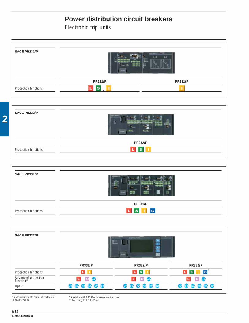
SACE PR231/P
PR231/P PR231/P
Protection functions /
SACE PR232/P
PR232/P
Protection functions
SACE PR331/P
PR331/P
Protection functions
SACE PR332/P
PR332/P PR332/P PR332/P
Protection functions (1)
Advanced protection function(*)
(***)
OT
(***)
OT
(***)
OT
Opt.(**) UV OV RV RP UF OF UV OV RV RP UF OF UV OV RV RP UF OF
(1) In alternative to Rc (with external toroid).(*) For all versions.
(**) Available with PR330/V. Measurement module.(***) According to IEC 60255-3.
1SXU210023D0201

2/13
2PR221DS-LS/I
1SDC210B05F0001
PR221DS − Tmax T2, T4, T5 and T6The PR221DS trip unit, available for T2,T4, T5 and T6, provides protection functions against overload L and short-circuit S/I (version PR221DS-LS/I): with this version you can choose whether to have inverse time-delay S or instantaneous I protection against short-circuit by moving the dedicated dip-switch. Al-ternatively, the version with only the protection function against instantaneous short-circuit I is available (version PR221DS-I, also see page 2/33 and following).There is a single adjustment for the phases and the neutral. The neutral is adjustable from 50 - 100% of the phases for Tmax T2 In = 160 A (T2 In<160 A, N = 100%), whereas for T4, T5 and T6 it is possible to select the protection threshold OFF, 50% or 100% directly from the front of the trip unit by means of the specifi c dip switch.The trip coil is always supplied with the PR221DS trip unit for Tmax T2 and is housed in the right-hand slot of the circuit breaker. Dedicated auxiliary contacts are available for T2 with electronic trip units (see page 3/21).For Tmax T4, T5 and T6, the opening solenoid is housed internally and therefore, by not using the right-hand slot of the circuit breaker, all the auxiliary contacts available can be used.
Protection LAgainst overload
Protection SAgainst short-circuit with delayed trip
Protection IAgainst short-circuit
with instantaneous trip
Socket for TT1 test unit
Dip-switch for neutral setting
(only for T4, T5 and T6)
PR221DS - Protection functions and settings
Protection functions Trip threshold Trip curves(1)
Against overload with long inverse time delay trip and trip characteristic according to an in-verse time curve (I2t=constant)
I1 = 0.40 - 0.44 - 0.48 - 0.52 - 0.56 - 0.60 - 0.64 - 0.68 - 0.72 - 0.76 - 0.80 - 0.84 - 0.88 - 0.92 - 0.96 - 1 x In
Release between 1.1...1.3 x I1 (IEC 60947-2 and UL 489)
at 6 x I1 at 6 x I1 at 6 x I1t1 = 3s t1 = 6s t1 = 12s only for T2 only for T4, T5
Tolerance: ± 10% up to 6 x In ± 20% above 6 x In
Against short-circuit with inverse short time delay trip and trip characteristic with inverse time (I2t=constant) (selectable as an alternative to protection function I)
I2 = 1 - 1.5 - 2 - 2.5 - 3 - 3.5 - 4.5 - 5.5 - 6.5 - 7 - 7.5 - 8 - 8.5 - 9 - 10 x In(2)
Tolerance: ± 10% (T4-T5) ± 10% up to 2 x In (T2) ± 20% above 2 x In (T2)
a 8 x In a 8 x In t2 = 0,1s t2 = 0,25s
Tolerance: ± 10% up to 6 x In (T4-T5) ± 20% above 6 x In (T4-T5) ± 20% (T2)
Against short-circuit with in-stantaneous trip (selectable as an alternative to protection function S)
I3 = 1 - 1,5 - 2 - 2,5 - 3 - 3,5 - 4,5 - 5,5 - 6,5 - 7 - 7,5 - 8 - 8,5 - 9 - 10 x In(3)
Tolerance: ± 10% (T4-T5) ± 20% (T2)
instantaneous
(1) These tolerances hold in the following conditions: – self-powered relay at full power and/or auxiliary supply; – two or three-phase power supply.
Trip timeS ± 20%I ≤ 40ms
(2) For T5 In = 600 A ⇒ I2 max = 9.5 x In (3) For T5 In = 600 A ⇒ I3 max = 9.5 x In
CANNOT BEEXCLUDED
CAN BEEXCLUDED
CAN BEEXCLUDED
In conditions other than those considered, the following tollerances hold:
1SXU210023D0201
2
2/14
PR222DS/P − Tmax T4, T5 and T6The PR222DS/P trip unit, available for T4, T5 and T6, has protection functions against overload L, delayed S and instantaneous I short-circuit (version PR222DS/P-LSI). Alternatively, in addition to the functions L, S, I, it also has protection against ground fault G (version PR222DS/P-LSIG).Setting of the PR222DS trip unit can be carried out either by means of dip switches on the front of the circuit breaker or electronically, using the PR010/T programming and control unit (see page 3/48) or the BT030 wireless communication unit (see page 3/45). There is a single setting for the phases and neutral for which one can decide whether to set the threshold of the protection functions to OFF, to 50% or to 100% of the phases by means of two dedicated dip switches.Furthermore, on the front of the PR222DS/P (or PR222DS/PD-A) trip units, signalling of pre-alarm and alarm of protection L is available. The pre-alarm threshold value, signalled by the red LED fi xed, is equal to 0.9 x I1. It is also possible to remotely transmit the alarm of protection L by simply connecting con-nector X3 to the dedicated contact.
PR222DS/PD-A − Tmax T4, T5 and T6Apart from the protection functions available for the PR222DS/P trip unit (for the settings see page 2/18), the PR222DS/PD-A trip unit, available for T4, T5 and T6 also has the communication unit integrated with Modbus® RTU protocol.The Modbus® RTU protocol has been known and used worldwide for many years and is now a market standard thanks to its simplicity of installation, confi guration and to its integration in the various different supervision, control and automation systems, as well as good level performances.The PR222DS/PD-A trip units allow the Tmax T4, T5 and T6 circuit breakers to be integrated in a com-munication network based on the Modbus® RTU protocol. Modbus® RTU provides a Master-Slave system architecture where a Master (PLC, PC…) cyclically interrogates several Slaves (fi eld devices). The devices use the EIA RS485 standard as the physical means for data transmission at a maximum transmission speed of 19.2 kbps.Again for this trip unit, the power supply needed for correct operation of the protection functions is sup-plied directly by the current transformers of the trip unit and tripping is always guaranteed, even under conditions of single-phase load down. Nevertheless, communication is only possible with an auxiliary power supply of 24 V DC.
The PR222DS/PD-A trip unit, with integrated communication and control functions, allows a wide range of information to be acquired and transmitted remotely, opening and closing commands to be carried out by means of the electronic version motor operator, the confi guration and programming parameters of the unit to be stored, such as the current thresholds of the protection functions and the protection curves.All the information can be consulted both locally, directly on the front of the circuit breaker with the front display unit FDU, or on the HMI030 switchgear multi-meter and remotely by means of supervision and control systems.Moreover, by connecting of the BT030 external module to the test connector of the PR222DS/PD-A trip unit, wireless communication to a PDA or Notebook is possible through a Bluetooth port.The PR222DS/PD-A trip units can be associated with the AUX-E auxiliary contacts to know the state of the circuit breaker (open/closed), and with MOE-E motor operator (the AUX-E are obligatory when MOE-E is to be used) to remotely control circuit- breaker opening and closing as well.If the circuit breaker fi tted with the PR222DS/PD-A trip unit is inserted in a supervision system, during the test phases with the PR010/T unit, communication is automatically abandoned and starts again on completion of this operation.
PR222DS/PD-A − Electrical characteristicsAuxiliary power supply (galvanically insulated) 24 V DC ± 20%
Maximum ripple ± 5%
Inrush current @ 24 V 1 A for 30 ms
Rated current @ 24 V 100 mA
Rated power @ 24 V 2.5 W
Power distribution circuit breakersElectronic trip units
1SXU210023D0201

2/15
2
Communication functions PR222DS/P PR222DS/PD-A
Protocol Modbus RTUstandard
Physical medium EIA RS485Speed (maximum) 19.2 kbpsMeasurement functionsPhase currents ■(1) ■
Neutral current ■(1) ■
Ground current ■(1) ■
Voltages (phase to phase, phase to ground)Powers (active, reactive, apparent)Power factorsEnergiesPeak factorFrequencySignalling functionsL pre-alarm and alarm LED ■(5) ■(5)
L alarm output contact(2) ■ ■
Available dataCircuit breaker status (open, closed)(3) ■
Mode (local, remote) ■
Protection parameters set ■(1) ■
AlarmsProtections: L, S, I, G ■(1) ■
Failed tripping under fault conditions ■(1) ■
MaintenanceTotal number of operations ■
Total number of trips ■
Number of trip tests ■
Number of manual operations ■
Number of trips for each individual protection function ■
Record of last trip data ■(1) ■
CommandsCircuit breaker opening/closing (with motor operator) ■
Alarm reset ■(1) ■
Circuit breaker reset (with motor operator) ■
Setting the curves and protection thresholds ■(1) ■
Safety function
Automatic opening in the case of failedTrip command fail (with motor operator)(4) ■
EventsChanges in circuit breaker state, in the protections and all the alarms ■
(1) With PR010/T unit or BT030 unit(2) Typical contact: MOS photo Vmax: 48 V DC/30 V AC Imax: 50 mA DC/35 mA AC(3) Available with AUX-E electronic auxiliary contacts(4) The motor operator must be in electronic version (MOE-E) and electronic auxiliary contacts (AUX-E) have to be used (5) Signals: – Pre-alarm L - permanently lit – Alarm L - fl ashing (0.5 s ON / 0.5 s OFF) – Incongruent manual setting (L > S / S > I) - fl ashing (1 s ON / 2 s OFF) – WINK (remote control to identify the relay) - fl ashing (0.125 s ON / 0.125 s OFF)
1SXU210023D0201

2
2/16
1SDC210B06F0001
PR222DS/PD-A
PR222DS/P
1SDC210B07F0001
Protection LAgainst overload
Protection SAgainst short-circuit with delayed trip Protection I
Against short-circuit with instantaneous trip
Socket for TT1 test unit
Dip-switch for neutral setting
Selection for electronic or manual setting
Socket for connection of PR010/T test unit and BT030 wireless communication unit
Protection LAgainst overload
Protection SAgainst short-circuit with delayed trip Protection I
Against short-circuit with instantaneous trip
Socket for TT1 test unit
Socket for connection of PR010/T test unit and BT030 wireless communication unit
Dip-switch for neutral setting
Selection for electronic or manual setting
Selection for local or remote setting
Power distribution circuit breakersElectronic trip units
1SXU210023D0201

2/17
2
Trip timeS ± 20%G ± 20%
(1) These tolerances hold in the following conditions:– self-powered relay at full power and/or auxiliary supply;– two or three-phase power supply.
In conditions other than those considered, the following tolerances hold:
(2) For T5 In = 600 A ⇒ t1 = 10.5s(3) For T5 In = 600 A ⇒ I3max = 9.5 x In I2max = 9.5 x In(4) Tolerance: ± 10 ms up to t2 = 0.1s
PR222DS/P, PR222DS/PD-A − Protection functions and settings
Protection functions Trip threshold Trip curves(1)
Against overload with long inverse time delay trip and trip characteristic according to an inverse t ime curve (I2t=constant)
Manual settingI1 = 0.40 - 0.42 - 0.44 - 0.46 - 0.48 - 0.50 - 0.52 - 0.54 - 0.56 - 0.58 - 0.60 - 0.62 - 0.64 - 0.66 - 0.68 - 0.70 - 0.72 - 0.74 - 0.76 - 0.78 - 0.80 - 0.82 - 0.84 - 0.86 - 0.88 - 0.90 - 0.92 - 0.94 - 0.96 - 0.98 - 1 x In
Manual settingat 6 x I1 at 6 x I1 at 6 x I1 at 6 x I1t1 = 3s t1 = 6s t1 = 9s t1 = 18s(2)
Electronic settingI1= 0.40…1 x In (step 0.01 x In)
Release between 1.1...1.3 x I1(IEC 60947-2 and UL 489)
Electronic settingat 6 x I1 t1 = 3…18s (step 0.5s)(2)
Tolerance: ± 10%
Against short-circuit with inverse short time delay trip and trip characteristic with inverse time (I2t=constant) or defi nite time
Manual settingI2 = 0.6 - 1.2 - 1.8 - 2.4 - 3.0 - 3.6 - 4.2 - 5.8 - 6.4 - 7.0 - 7.6 - 8.2 - 8.8 - 9.4 - 10 x In(3)
Manual settingat 8 x In at 8 x In at 8 x In at 8 x Int2 = 0.05s t2 = 0.1s t2 = 0.25s t2 = 0.5s
Electronic settingI2 = 0.60…10 x In (step 0.1 x In) (3)
Tolerance: ± 10%
Electronic settingat 8 x In t2 = 0.05…0.5s (step 0.01s)
Tolerance: ± 10%(4)
Manual settingI2 = 0.6 - 1.2 - 1.8 - 2.4 - 3.0 - 3.6 - 4.2 - 5.8 - 6.4 - 7.0 - 7.6 - 8.2 - 8.8 - 9.4 - 10 x In(3)
Manual settingt2 = 0.05s t2 = 0.1s t2 = 0.25s t2 = 0.5s
Electronic settingI2 = 0.60…10 x In (step 0.1 x In)(3)
Tolerance: ± 10%
Electronic settingt2 =0.05…0.5s (step 0.01s)
Tolerance: ± 10%(4)
Against short-circuit with instan-taneous trip
Manual settingI3 = 1 .5 - 2 . 5 - 3 - 4 - 4 . 5 - 5 -
5 . 5 - 6 . 5 - 7 - 7 . 5 - 8 - 9 - 9.5 - 10.5 - 12 x In(3)
instantaneous Electronic settingI3 = 1.5…12 x In (step 0.1 x In) (3)
Tolerance: ± 10%
Against ground fault with inverse short time delay trip and trip characteristic according to an inverse time curve (I2t= constant)
Manual settingI4 = 0.2 - 0.25 - 0.45 - 0.55 - 0.75 - 0.8 - 1 x In
Manual settingup to up to up to up to3.15 x I4 2.25 x I4 1.6 x I4 1.10 x I4 t4 = 0.1s t4 = 0.2s t4 = 0.4s t4 = 0.8s
Electronic settingI4 = 0.2…1 x In (step 0.01 x In)
Tolerance: ± 10%
Electronic settingt4 = 0.1...0.8 x In (step 0.01s)
Tolerance: ± 20%
I2t=const ON
I2t=const OFF
CANNOT BEEXCLUDED
CAN BEEXCLUDED
CAN BEEXCLUDED
CAN BEEXCLUDED
1SXU210023D0201
2
2/18
1SDC210B54F0001
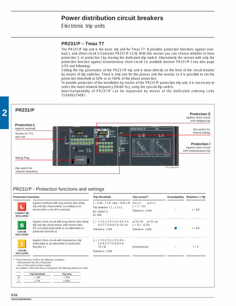
PR231/P – Tmax T7The PR231/P trip unit is the basic trip unit for Tmax T7. It provides protection functions against over-load L and short-circuit S/I (version PR231/P-LS/I). With this version you can choose whether to have protection S or protection I by moving the dedicated dip-switch. Alternatively the version with only the protection function against instantaneous short-circuit I is available (version PR231/P-I see also page 2/33 and following). Setting the trip parameters of the PR231/P trip unit is done directly on the front of the circuit breaker by means of dip switches. There is only one for the phases and the neutral, so it is possible to set the protection threshold at 50% or at 100% of the phase protection. To provide protection of the installation by means of the PR231/P protection trip unit, it is necessary to select the rated network frequency (50/60 Hz), using the special dip-switch.Interchangeability of PR231/P can be requested by means of the dedicated ordering code 1SDA063140R1.
PR231/P
PR231/P - Protection functions and settings
Protection functions Trip threshold Trip curves(1) Excludability Relation t = f(I)
Against overload with long inverse time delay trip and trip characteristic according to an inverse time curve (I2t=constant)
I1 = 0.40...1 x In step = 0.04 x In
Trip between 1.1...1.3 x I1IEC 60947-2 UL 489
at 6 x I1 at 6 x I1t1 = 3 - 12s
Tolerance: ±10% – t = k/I2
Against short-circuit with long inverse time delay trip and trip characteristic with inverse time (I2t=constant) (selectable as an alternative to protection function I)
I2 = 1-1.5-2-2.5-3-3.5-4.5-5.5-6.5-7-7.5-8-8.5-9-10 x In
Tolerance: ±10%
at 10 x In at 10 x In t2 = 0.1 - 0.25s
Tolerance: ±10% ■ t = k/I2
Against short-circuit with istantaneous trip (selectable as an alternative to protection function S)
I3 = 1-1.5-2-2.5-3-3.5-4.5-5.5-6.5-7-7.5-8-8.5-9-10 x In
Tolerance: ±10%
instantaneous – t = k
(1) These tolerances hold in the following conditions: – self-powered trip unit at full power – two or three-phase power supply In conditions other than those considered, the following tollerances hold:
Trip threshold Trip timeS ± 10% ± 20%I ± 15% ≤ 60ms
Protection IAgainst short-circuit
with instantaneous trip
Rating Plug
Protection LAgainst overload
Protection SAgainst short-circuit
with delayed trip
Socket for TT1 test unit
Dip-switch for neutral setting
Dip-switch for network frequency
CANNOT BEEXCLUDED
CAN BEEXCLUDED
CAN BEEXCLUDED
Power distribution circuit breakersElectronic trip units
1SXU210023D0201

2/19
2
PR232/P
1SDC210B55F0001
PR232/P – Tmax T7The PR232/P trip unit, available for T7, provides protection functions against overload L, delayed short-circuit S and instantaneous short-circuit I (version PR232/P-LSI).Setting the trip parameters (see table) of the PR232/P trip unit can be carried out by means of the dip-switches it is unique for the phases and the neutral, for which it is possible to set the protection threshold to OFF, to 50%, 100% or 200% of the threshold of the phases directly from the front of the trip unit with a special dip-switch. In particular, adjustment of the neutral to 200% of the phase current requires setting protection L to respect the current-carrying capacity of the circuit breaker.To provide protection of the installation by means of the PR232/P protection trip unit, it is necessary to select the rated network frequency (50/60 Hz) with the special dip-switch.
PR232/P - Protection functions and settings
Protection functions Trip threshold Trip curves(1) Thermalmemory(2) Excludability Relation
t = f(I)
Against overload with long inverse time delay trip and trip characteristic according to an inverse time curve (I2t=constant)
I1 = 0.40...1 x In step = 0.04 x In
Trip between 1.1...1.3 x I1IEC 60947-2 UL 489
at 6 x I1 t1 = 3s t1 = 6s t1 = 12s t1 = 18s
Tolerance: ±10% ■ – t = k/I2
Against short-circuit with inverse short time delay trip and trip characteristic w i t h i n v e r s e t i m e (I2t=constant) or defi nite time
I2 = 0.6 - 0.8 - 1.2 - 1.8 - 2.4 - 3 - 3.6 - 4.2 - 5 - 5.8 - 6.6 - 7.4 - 8.2 - 9 - 10 x In
Tolerance: ±10%
at 10 x Int2=0.1s t2=0.25s t2=0.5s t2=0.8s
Tolerance: ±10% ■ ■ t = k/I2
I2 = 0.6 - 0.8 - 1.2 - 1.8 - 2.4 - 3 - 3.6 - 4.2 - 5 - 5.8 - 6.6 - 7.4 - 8.2 - 9 - 10 x In
Tolerance: ±10%
I > I2t2=0.1s t2=0.25s t2=0.5s t2=0.8s
Tolerance: ±10% – ■ t = k
Against short-circuit with istantaneous trip
I3 = 1.5 - 2.5 - 3 - 4 - 4.5 - 5 - 5.5 - 6.5 - 7 - 7.5 - 8 - 9 - 9.5 - 10.5 - 12 x In
Tolerance: ±10%
instantaneous – ■ t = k
Protection IAgainst short-circuit with instantaneous trip
Protection LAgainst overload
Socket for connection of SACE PR010/T, BT030 and PR030/B
Rating Plug
Protection SAgainst short-circuit with delayed trip
LED signalling Alarm for protection function S
LED signalling Alarm for protection function I
LED signalling Alarm for protection function L
Socket for TT1 test unit
Dip-switch for network frequency
Dip-switch for neutral setting
Trip threshold Trip timeS ± 10% ± 20%I ± 15% ≤ 60ms
CANNOT BEEXCLUDED
CAN BEEXCLUDED
CAN BEEXCLUDED
(1) These tolerances hold in the following conditions: – self-powered trip unit at full power (without start-up) – two or three-phase power supply
In conditions other than those considered, the following tollerances hold:
(2) Active up to 7 min. after tripping of the breaker (ON/OFF setting by means of PR010/T test unit).
1SXU210023D0201

2
2/20
There are three red LEDs available on the front of the PR232/P trip unit dedicated to the signalling alarm of protections L, S, and I. Furthermore, a yellow fl ashing LED allows the state of pre-alarm of function L to be signalled, which is activated when 90% of the set trip threshold is reached. The yellow fl ashing LED every 3s indicates the normal operation.
PR232/P - Alarm and Pre-alarm LED
Protection Colour Pre-alarm Alarm Last trip
Yellow ■ – –
Red – ■ ■
Red – ■ ■
Red – ■ ■
Following circuit breaker opening, it is possible to know which protection function made the trip unit trip by connecting the PR030/B battery unit onto the front of the trip unit. This is also possible thanks to the PR010/T test and confi guration unit. By means of the BT030 wireless communication unit the PR232/P can be connected to a PDA or to a personal computer, extending the range of information available for the user. In fact, by means of the ABB SACE’s SD-Pocket communication software, it is possible to read the values of the currents fl owing through the circuit breaker, the value of the last 20 interrupted currents, and the protection settings.
Power distribution circuit breakersElectronic trip units
1SXU210023D0201

2/21
2
PR331/P
1SDC210B56F0001
PR331/P – Tmax T7The PR331/P, available for Tmax T7 in the PR331/P-LSIG version, is suitable for protecting a wide range of alternating current installations with its complete range of protection functions together with the wide combination of thresholds and trip times offered. In addition the unit is provided with multifunction LED indicators. Furthermore, PR331/P allows connection to external devices enhancing its advanced char-acteristics like remote signalling and monitoring, or interface from front of HMI030 panel.
PR331/P - Protection functions and settings
Protection functions Trip threshold Trip curves(1) Excludability Relation t = f(I)
Against overload with long inverse time-delay trip and trip characteristic according to an inverse time curva (I2t=k)
I1 = 0.40….1 x In step = 0.025 x In
Trip between 1.05 ... 1.2 x I1
at 3 x I1 t1 = 3 - 12 - 24 - 36 - 48 - 72 - 108 - 144s
Tolerance: ±10% up to 6 x In ±20% above 6 x In
– t = k/I2
Against short-circuit with short inverse time-delay trip and trip characteristic with inverse time (I2t=k) or with defi nite time
I2 = 0.6 - 0.8 - 1.2 - 1.8 - 2.4 - 3 - 3.6 - 4.2 - 5 - 5.8 - 6.6 - 7.4 - 8.2 - 9 - 10 x In
Tolerance: ±7% up to 6 x In ±10% above 6 x In
at 10 x In t2 = 0.1….0.8s step = 0.1s
Tolerance: min (±10%. ±40ms) ■ t = k/I2
I2 = 0.6 - 0.8 - 1.2 - 1.8 - 2.4 - 3 - 3.6 - 4.2 - 5 - 5.8 - 6.6 - 7.4 - 8.2 - 9 - 10 x In
Tolerance: ±7% up to 6 x In ±10% above 6 x In
I > I2t2 = 0.1….0.8s step = 0.1s
Tolerance: ±15% up to 6 x In ±20% above 6 x In
■ t = k
Against short-circuit with adjustable instantaneous trip
I3 = 1.5 - 2 - 3 - 4 - 5 - 6 - 7 - 8 - 9 - 10 - 11 - 12 - 13 - 14 - 15 x In(2)
Tolerance: ±10% ≤ 30 ms ■ t = k
Against ground fault with short inverse time-delay trip and trip characteristic according to an inverse time curve (I2t=k) or with defi nite time
I4 = 0.2 - 0.3 - 0.4 - 0.6 - 0.8 - 0.9 - 1 x In
Tolerance: ±7%
4.47 x I4 3.16 x I4 2.24 x I4 1.58 x I4t4=0.1s t4=0.2s t4=0.4s t4=0.80s
Tolerance: ±15%■ t = k/I2 (3)
I4 = 0.2 - 0.3 - 0.4 - 0.6 - 0.8 - 0.9 - 1 x In
Tolerance: ±7%
t4=0.1s t4=0.2s t4=0.4s t4=0.80s
Tolerance: min (±10%. ±40ms) ■ t = k
Protection IAgainst short-circuit with instantaneous trip
Protection LAgainst overload
Socket for connection of SACE PR010/T, BT030 and PR030/B
Protection GAgainst ground fault
Info/test push button
Dip-switch for network frequency
Rating Plug
Protection SAgainst short-circuit with delayed trip
(1) These tolerances hold in the following conditions: – self-powered trip unit at full power and/or auxiliary supply – two or three-phase power supply In conditions other than those considered, the following
tollerances hold:
LED signalling Alarm for protection function S
LED signalling Alarm for protection function I
LED signalling Alarm for protection function G
LED signalling Alarm and prealarm for protection function L
Trip threshold Trip timeL Release between 1.05 and 1.25 x I1 ± 20%S ± 10% ± 20%I ± 15% ≤ 60msG ± 15% ± 20%
(2) For T7 In = 1200 A ⇒ I3max = 12 x In(3) t = k/I2 up to the current value indicated, t = k equating to the chosen setting) beyond the current value indicated
Dip-switch for neutral setting
CANNOT BEEXCLUDED
CAN BEEXCLUDED
CAN BEEXCLUDED
CAN BEEXCLUDED
1SXU210023D0201

2
2/22
User interface
The user communicates directly with the trip unit by means of the dip switches. Up to four LEDs (according to the version) are also available for signalling. These LEDs (one for each protection) are active when:• a protection is timing. For protection L the pre-alarm status is also shown;• a protection has tripped (the corresponding LED is activated by pressing the “Info/Test” pushbut-
ton);• a failure in connection of a current sensor or in the trip coil is detected. The indication is active when
the unit is powered (through current sensors or an auxiliary power supply)• wrong rating plug for the circuit breaker. The protection tripped indication works even with the circuit breaker open, without the need for any internal or external auxiliary power supply. This information is available for 48 hours of inactivity after the trip and is still available after reclosing. If the query is made more than 48 hours later it is suffi cient to connect a PR030/B battery unit, PR010/T, or a BT030 wireless communication unit.
Setting the neutral
Protection of the neutral can be set at 50%, 100% or 200% of the phase currents. In particular, adjust-ment of the neutral at 200% of the phase current is possible if the following inequality is respected: I1 x In x %N < Iu. The user can also switch the neutral protection OFF.
Test function
The Test function is carried out by means of the Info/Test pushbutton and the PR030/B battery unit (or BT030) fi tted with a polarized connector housed on the bottom of the box, which allows the device to be connected to the test connector on the front of PR331/P trip units. The PR331/P electronic trip unit can be tested by using the SACE PR010/T test and confi guration unit by connecting it to the TEST connector.
Power supply
The unit does not require an external power supply for protection functions or for alarm signalling func-tions. It is self-supplied by means of the current sensors installed on the circuit breaker.For operation, it is required for the three phases to be passed through by a current of 70 A. An external power supply can be connected in order to activate additional features, and in particular for connection to external devices: HMI030 and PR021/K.
PR331/P - Electrical characteristicsAuxiliary power supply (galvanically insulated) 24 V DC ± 20%
Maximum ripple ± 5%
Inrush current @ 24 V ~1 A for 5 ms
Rated power @ 24 V ~2 W
Communication
By means of the BT030 wireless communication unit, PR331/P can be connected to a PDA or to a personal computer, extending the range of information available for the user. In fact, using ABB’s SD-Pocket communication software, it is possible to read the values of the currents fl owing through the circuit breaker, the value of the last 20 interrupted currents, and the protection settings.PR331/P can also be connected to the optional external PR021/K signalling unit, for the remote signalling of protections alarms and trips, and to HMI030, for the remote user interfacing.
Power distribution circuit breakersElectronic trip units
1SXU210023D0201

2/23
2PR332/P
1SDC210B58F0001
1SDC210B57F0001
PR332/P – Tmax T7The SACE PR332/P trip unit for Tmax T7 (available in four versions: PR332/P-LI, PR332/P-LSI, PR332/P-LSIG) is a sophisticated and fl exible protection system based on a state-of-the art microprocessor and DSP technology. Fitted with the optional internal PR330/D-M dialogue unit, PR332/P turns into an intelligent protection, measurement and communication device based on the Modbus® RTU protocol. By means of the PR330/D-M, PR332/P can also be connected to the ABB EP010 Fieldbus plug adapter, which makes it possible to choose among several different networks, such as Profi bus and DeviceNet.The new PR332/P is the result of ABB SACE’s experience in designing trip units. The exhaustive range of settings makes this protection unit ideal for general use in power distribution.Access to information and programming using a keyboard and graphic liquid crystal display is extremely simple and intuitive. An integrated ammeter and many other additional features are provided over and above the protection functions. These additional functions can be further increased with addition on board of the dialogue, signalling, measurement, and wireless communication units. All the thresholds and trip curve delays of the protection functions are stored in special memories which retain the information even when no power is supplied.
Alarm LED
Warning indicator LED
ENTER button to confi rm data or change pages
Cursor UP button
Cursor DOWN button
Button to exit submenus or cancel
operations (ESC)
Info/test push button
Rating Plug
Alarm LED
Warning indicator LED
ENTER button to confi rm data or change pagesCursor UP button
Cursor DOWN button
Button to exit submenus or cancel operations (ESC)
Info/test push buttonRating Plug
PR330/V measurement module
Selector for setting the voltage source for
PR330/V (EXT, TEST, INT)
PR330/V power supply LED
PR332/P with PR330/V
1SXU210023D0201

2
2/24
(1) These tolerances are valid under the following conditions: – trip unit self-supplied at full power and/or auxiliary supply – two or three-phase power supply In conditions other than those considered, the following tollerances hold:
Trip threshold Trip timeL Release between 1.05 and 1.25 x I1 ± 20%
S ± 10% ± 20%
I ± 15% ≤ 60ms
G ± 15% ± 20%
Other ± 10% ± 20%
(2) Active with 24V auxiliary power supply (3α - 1)(3) t = t1 (3 x I1) ( I )α - 1 I1(4) For T7 In = 1000 A ⇒ I3max = 12 x In(5) k = (2s) · (I4)
2
PR332/P - Protection functions and settings
Protection functions Trip threshold Trip curves(1) Excludability Relation t = f(I)
Thermal memory(2)
Zone selectivity(2)
Against overload with inverse long-time delay trip
I1 = 0.4…1 x In step = 0.01 x In
Trip between 1.05...1.2 x I1
at I = 3 x I1
t2 = 3…144s step = 3s
Tolerance: ±10% up to 6 x In ±20% above 6 x In
– t = k/I2 ■ –
I1 = 0.4…1 x In step = 0.01 x In
Trip between 1.05...1.2 x I1
t2 = 3…144s step = 3s
Tolerance: ±10% up to 6 x In ±20% above 6 x In
■t = f(α)(3)
α = 0.02-1-2■ –
Against short-circuit with short inverse time-delay trip and trip characteristic with inverse time (I2t=k) or with defi nite time
I2 = 0.6…10 x In step = 0.1 x In
Tolerance: ±7% up to 6 x In ±10% above 6 x In
at 10 x Int2 = 0.05…0.8s step = 0.01s
Tolerance: ±15% up to 6 x In ±20% over 6 x In
■ t = k/I2 ■ –
I2 = 0.6…10 x In step = 0.1 x In
Tolerance: ±7% up to 6 x In ±10% above 6 x In
t2 = 0.05…0.8s step = 0.01s
t2 sel = 0.04...0.2s step = 0.01s
Tolerance: min (±10%; ±40ms) ■ t = k – ■
Against short-circuit with adjustable instantaneous trip
I3 = 1.5…15 x In step = 0.1 x In
Tolerance: ±10% ≤ 30 ms ■ t = k – –
Against ground fault with short inverse time-delay trip and trip characteristic according to an inverse time curve (I2t=k) or with defi nite time
I4 = 0.2…1 x In step = 0.02 x In
Tolerance: ±7%
t4 = 0.1…1s step = 0.05s
Tolerance: ±15%■ t = k/I2 (5) – –
I4 = 0.2…1 x In step = 0.02 x In
Tolerance: ±7%
t4 = 0.1…1s step = 0.05s
t4 sel = 0.04...0.2s step = 0.05s
Tolerance: min (±10%; ±40ms) ■ t = k – ■
OTAgainst overtemperature of the trip unit with instantaneous trip
Trip unit temperature over 85 °C
instantaneous – temp =k – –
Against unbalanced phase with defi nite time-delay trip
I6 = 2%…90% x I
1 step = 1% x I
1
Tolerance: ±10%
t6 = 0.5…60 s step = 0.5s
Tolerance: min (±20%; ±100ms) ■ t = k – –
PR332/P with PR330/V - Advanced protection functions and settings
Advanced protection functions Trip threshold Trip curves(1) Excludability Relation t = f(I)
Thermal memory(2)
Zoneselectivity
UVAgainst undervoltage with adjustable constant time
U8= 0.5…0.95 x Un step = 0.01 x Un
Tolerance: ±5%
t8 = 0.1…5s step = 0.1s
Tolerance: min (±20% ±100ms) ■ t = k – –
OVAgainst overvoltage with adjustable constant time
U9= 1.05...1.2 x Un step = 0.01 x Un
Tolerance: ±5%
t9 = 0.1…5s step = 0.1s
Tolerance: min (±20% ±100ms) ■ t = k – –
RVAgainst residual voltage with adjustable constant time
U10
= 0.1…0.4 x Un step = 0.01 x Un
Tolerance: ±5%
t10
= 0.5…30s step = 0.5s
Tolerance: min (±10% ±100ms) ■ t = k – –
RPAgainst reversal of power with adjustable constant time
P11
= -0.3…-0.1 x Pn step = 0.02xPn
Tolerance: ±10%
t11
= 0.5…25s step = 0.1s
Tolerance: min (±10% ±100ms) ■ t = k – –
UFAgainst underfrequency with adjustable constant time
f12
= 0.90…0.99 x fn step = 0.01 x fn
Tolerance:±5%
t12
= 0.5…3s step = 0.1s
Tolerance: min (±10% ±100ms) ■ t = k – –
OFAgainst overfrequency with adjustable constant time
f13
= 1.01…1.10 x fn step = 0.01 x fn
Tolerance:±5%
t13
= 0.5…3s step = 0.1s
Tolerance: min (±10% ±100ms) ■ t = k – –
Power distribution circuit breakersElectronic trip units
1SXU210023D0201

2/25
2
Setting the neutral
In PR332/P, the neutral protection is 50% of the value set for phase protection in the standard version. The neutral protection can be excluded or set to 100%. In installations where very high harmonics occur, the resulting current at the neutral can be higher than that of the phases. Therefore it is possible to set the neutral protection at 150% or 200% of the value set for the phases. In this case it is necessary to reduce the setting of L protection accordingly. The table below lists the neutral settings for the various possible combinations between type of circuit breaker and the threshold I1 setting.
Adjustable neutral protection settings
Threshold I1 settings (overload protection)
Circuit breaker model 0.4 < I1 < 0.5 0.5 < I1 < 0.66 0.66 < I1 < 1(*)
T7 0-50-100-150-200% 0-50-100-150% 0-50-100%(*) The setting I1 =1 indicates the maximum overload protection setting. The actual maximum setting allowable must take into account any derating based
on temperature, the terminals used and the altitude (see the “Installations” chapter)
Start-up function
The start-up function allows protections S, I and G to operate with higher trip thresholds during the start-up phase. This avoids untimely tripping caused by the high inrush currents of certain loads (motors, transformers, lamps).The start-up phase lasts from 100 ms to 30 s, in steps of 0.01 s. It is automatically recognized by the PR332/P trip unit when the peak value of the maximum current exceeds the threshold that can be set by the user. A new start-up becomes possible after the current has fallen down to 0.1 x In, if the trip unit is supplied from an external source.
Protection against overtemperature
The user has the following signals or commands available for protection against overtemperature:– lighting up of the “Warning” LED when the temperature is higher than 70 °C or lower than -20 °C
(temperature at which the microprocessor is still able to operate correctly);– lighting up of the “Alarm” LED when the temperature is higher than 85 °C or lower than -25 °C (tem-
perature above which the microprocessor can no longer guarantee correct operation) and, when decided during the unit confi guration stage, simultaneous opening of the circuit breaker with indication of the trip directly on the display, as for the other protections.
Self-diagnosis
The PR332/P range of trip units contains an electronic circuit which periodically checks the continuity of internal connections (trip coil and each current sensor, including the Source Ground Return when present).In the case of a malfunction an alarm message appears directly on the display. The Alarm is highlighted by the Alarm LED as well.
Test Functions
Once enabled from the menu, the “Info/Test” pushbutton on the front of the trip unit allows correct op-eration of the chain consisting of the microprocessor, trip coil and circuit breaker tripping mechanism to be checked.The control menu also includes the option of testing correct operation of the display, signalling LEDs.By means of the front multi-pin connector it is possible to apply a SACE PR010/T Test unit which allows the functions of the PR222DS/P, PR222DS/PD-A, PR232/P, PR331/P and PR332/P ranges of trip units to be tested and checked.
1SXU210023D0201

2
2/26
User interface
The human-machine interface (HMI) of the device is made up of a wide graphic display, LEDs, and brows-ing pushbuttons. The interface is designed to provide maximum simplicity.The language can be selected from among fi ve available options: Italian, English, German, French and Spanish.As in the previous generation of trip units, a password system is used to manage the “Read” or “Edit” modes. The default password, 0001, can be modifi ed by the user.The protection parameters (curves and trip thresholds) can be set directly via the HMI of the device. The parameters can only be changed when the trip unit is operating in “Edit” mode, but the information available and the parameter settings can be checked at any time in “Read” mode. When a communication device (internal PR330/D-M module or external BT030 device) is connected, it is possible to set parameters simply by downloading them into the unit (over the network for PR330/D-M, by using the SD-Pocket software and a PDA or a notebook for BT030). Settings can then be carried out quickly and automatically in an error-free way by transferring data directly from DocWin.
Indicator LEDs
LEDs on the front panel of the trip unit are used to indicate all the warnings and alarms. A message on the display always explicitly indicates the type of event that has concerned.Example of events indicated by the “WARNING” LED:– unbalance between phases;– pre-alarm for overload (L1>90% x I1);– fi rst temperature threshold exceeded (70 °C);– contact wear beyond 80%;– phase rotation reversed (with optional PR330/V).
Example of events indicated by the “ALARM” LED:– timing of function L;– timing of function S;– timing of function G;– second temperature threshold exceeded (85 °C);– contact wear 100%;– timing of Reverse Power fl ow protection (with optional PR330/V).
Data logger
PR332/P is provided with the Data Logger function that automatically records the instantaneous values of all the currents and voltages in a wide memory buffer. Data can be easily downloaded from the unit by means of SD-Pocket or SD-TestBus2 applications and can be transferred to any personal computer for elaboration. The function freezes the recording whenever a trip occurs or in case of other events, so that a detailed analysis of faults can be easily performed. SD-Pocket and SD-TestBus2 also allow reading and downloading of all the other trip information.• Number of analog channels: 8• Maximum sampling rate: 4800 Hz• Maximum sampling time: 27 s (@ sampling rate 600 Hz)• 64 events tracking.
Power distribution circuit breakersElectronic trip units
1SXU210023D0201

2/27
2
Trip information and opening data
In case a trip occurs PR332/P store all the needed information:• Protection tripped• Opening data (current)• Time stamp (guaranteed with auxiliary supply or self-supply with power failure no longer than 48h).By pushing the “Info/Test” pushbutton the trip unit shows all these data directly on display.No auxiliary power supply is needed. The information is available to user for 48 hours with the circuit breaker open or without current fl owing.The information of the latest 20 trips are stored in memory.If the information can be furthermore retrieved more than 48 hours later, it is suffi cient to connect a PR030/B battery unit or a BT030 wireless communication unit.
Load control
Load control makes it possible to engage/disengage individual loads on the load side before the overload protection L is tripped, thereby avoiding unnecessary trips of the circuit breaker on the supply side. This is done by means of contactors or disconnect switches (externally wired to the trip unit), controlled by the PR332/P through PR021/K unit.Two different Load Control schemes can be implemented:– disconnection of two separate loads, with different current thresholds– connection and disconnection of a load, with hysteresis.Current thresholds and trip times are smaller than those available for selection with protection L, so that load control can be used to prevent overload tripping. External PR021/K accessory unit is required for Load Control. The function is only active when an auxiliary power supply is available.
PR330/V Measurement Module
This optional internal module, installed in PR332/P, allows the trip unit to measure the phase and neutral voltages and to process them in order to achieve a series of features, in terms of protection and mea-surement.The PR330/V module when ordered mounted on the circuit breaker, does not require any external con-nection or voltage transformers since it is connected internally to the upper terminals of Tmax T7 (selector in “INT” position) through the internal voltage sockets. When necessary, the connection of voltage pick-ups can be moved to any other point (i.e. lower terminals), by using the alternative connection located in the terminal box and by switching the selector to the “EXT” position. For the dielectric test of the circuit breaker the selector must be switched to the “Insulating TEST” position. PR330/V is able to energize the PR332/P while line voltage input is above 85 V. The use of Voltage Transformers is mandatory for rated voltages higher than 690 V.Voltage transformers shall have burdens between 5 VA and 10 VA and accuracy class 0.5 or better.Additional Protections with PR330/V:– Undervoltage (UV) protection– Overvoltage (OV) protection– Residual voltage (RV) protection– Reversal of power (RP) protection– Underfrequency (UF) protection– Overfrequency (OF) protection.All the above indicated protections can be excluded, although it is possible to leave only the alarm active when required: in this case the trip unit will indicate the “ALARM” status. With the circuit breaker closed, these protections also operate when the trip unit is self-supplied. With the circuit breaker open, they operate when the auxiliary power supply (24 V DC or PR330/V) is present.
1SXU210023D0201

2
2/28
Measurement function
The current measurement function (ammeter) is present on all versions of the PR332/P trip unit. The display shows histograms showing the currents of the three phases and neutral on the main page. Fur-thermore, the most loaded phase current is indicated in numerical format. Ground fault current, where applicable, is shown on a dedicated page.The latter current value takes on two different meanings depending on whether the external toroidal trans-former for the “Source Ground Return” function or the internal transformer (residual type) is connected.The ammeter can operate either with self-supply or with an auxiliary power supply voltage. The display is rear-lit and the ammeter is active even at current levels lower than 160 A.Accuracy of the ammeter measurement chain (current sensor plus ammeter) is no more than 1.5% in the 0.3-6 x In current interval of In.– Currents: three phases (L1, L2, L3), neutral (Ne) and ground fault;– Instantaneous values of currents during a period of time (data logger);– Maintenance: number of operations, percentage of contact wear, opening data storage (last 20 trips
and 20 events).When the optional PR330/V is connected the following additional measurement functions are present:– Voltage: phase-phase, phase-neutral and residual voltage– Instantaneous values of voltages during a period of time (data logger)– Power: active, reactive and apparent– Power factor– Frequency and peak factor– Energy: active, reactive, apparent, counter.
Communication
PR332/P electronic trip unit can be fi tted with communication modules, which make possible to exchange data and information with other industrial electronic devices by means of a network.The basic communication protocol implemented is Modbus RTU, a well-known standard of widespread use in industrial automation and power distribution equipment. A Modbus RTU communication interface can be connected immediately and exchange data with the wide range of industrial devices using the same protocol. ABB has developed a complete series of accessories for electronic trip unit PR332/P:– PR330/D-M is the communication module for PR332/P protection trip units. It is designed to allow
easy integration of the Tmax circuit breakers in a Modbus network. The Modbus RTU protocol is used widely in the power and the automation industries. It is based on a master/slave architecture, with a bandrate of up to 19.2 kbps. A standard Modbus network is easily wired up and confi gured by means of an RS485 physical layer. ABB SACE trip units work as slaves in the fi eld bus network. All information required for simple integration of PR330/D-M in an industrial communication system is available on the ABB Web page.
– BT030 is a device to be connected to the Test connector of PR222DS/P, PR222DS/PD-A, PR232/P, PR331/P and PR332/P trip units. It allows Bluetooth communication between the trip unit and a PDA or a Notebook with a Bluetooth port. This device is dedicated to use with the SD-Pocket or SD-TestBus2 application. It can provide the auxiliary supply needed to energize the protection trip unit by means of rechargeable batteries.
– EP010-FBP-PDP22 is the Fieldbus Plug interface allows connection of ABB SACE trip units with Modbus communication to a Profi bus, DeviceNet, or AS-I fi eld bus network.
Furthermore, a new generation of software dedicated to installation, confi guration, supervision and control of protection trip units and circuit- breakers is now available:– SD-View 2000– SD-Pocket– SD-TestBus2.
All information required for simple integration of PR330/D-M in an industrial communication system are available on the ABB Web page (http://www.abb.com).
Power distribution circuit breakersElectronic trip units
1SXU210023D0201

2/29
2
Measurement, signalling and available data functionsDetails about functions available on PR332/P, trip units with PR330/D-M and EP010 – FBP – PDP22 are listed in the table below:
Communication functions PR332/P + PR330/D-MPR332/P + PR330/D-M
and EP010Protocol Modbus RTU
standardFBP-PDP22
Physical means RS485 Profi bus-DP or DeviceNet cableSpeed (maximum) 19.2 kbps 115 kbpsMeasurement functionsPhase currents ■ ■
Neutral current ■ ■
Ground current ■ ■
Voltage (phase-phase, phase-neutral, residual) opt.(1) opt.(1) (2)
Power (active, reactive, apparent) opt.(1) opt.(1) (3)
Power factor opt.(1) (4)
Frequency and peak factor opt.(1) (4)
Energy (active, reactive, apparent) opt.(1) (4)
Harmonic analysis – –Signalling functionsLED: auxiliary power supply, pre-alarm, alarm, transmission, reception ■ ■
Temperature ■ ■
Indication for L, S, I, G and other protection ■ ■
Available dataCircuit breaker status (open, closed) ■ ■
Circuit breaker position (racked-in, racked-out) ■ ■
Mode (local, remote) ■ ■
Protection parameters set ■ ■
Load control parameters ■ ■
AlarmsProtections: L, S, I, G ■ ■
Undervoltage, overvoltage and residual voltage protection (timing and trip) opt.(1) opt.(1)
Reverse power protection (timing and trip) opt.(1) opt.(1)
Directional protection (timing and trip) – –Underfrequency/overfrequency protection (timing and trip) opt.(1) opt.(1)
Phases rotation – –Failed tripping under fault conditions ■ ■
MaintenanceTotal number of operations ■ ■
Total number of trips ■ ■
Number of trip tests ■ ■
Number of manual operations ■ ■
Number of separate trips for each protection function ■ ■
Contact wear (%) ■ ■
Record data of last trip ■ ■
CommandsCircuit breaker open/close ■ ■
Alarms reset ■ ■
Setting of curves and protection thresholds ■ ■
Synchronize system time ■ ■
EventsStatus changes in circuit breaker, protections and all alarms ■ ■
(1) With PR330/V (2) No residual voltage (3) No apparent power available (4) Please ask ABB for further details
1SXU210023D0201

2
2/30
Power supplyThe PR332/P trip unit does not normally require any external power supplies, being self-supplied from the current sensors (CS): to activate the protection and ammeter functions, it is suffi cient for at least one phase to have a current load higher than 80 A.The unit ensures fully self-supplied operation. When an auxiliary power supply is present, it is also pos-sible to use the unit with the circuit breaker either open or closed with very low current fl owing through (<80 A).It is also possible to use an auxiliary power supply provided by the PR030/B portable battery unit, which allows the protection functions to be set when the trip unit is not self supplied.PR332/P stores and shows all the information needed after a trip (protection tripped, trip current, time, date). No auxiliary supply is required.
PR332/P PR330/D-M
Auxiliary power supply (galvanically insulated) 24 V DC ± 20% from PR332/P Maximum ripple ± 5% ± 5%Inrush current @ 24 V ~1 A for 5 ms ~0.5 A for 5 msRated power @ 24 V ~3 W +1 W
PR330/V can give power supply to the trip unit when at least one line voltage is equal or higher to 85V RMS.
Power distribution circuit breakersElectronic trip units
1SXU210023D0201


2
2/33
Motor Control Protection circuit breakers: MCP
Index
Motor Control Protection circuit breakers: MCP
Electrical characteristics ..............................................................................................................2/34
General characteristics .................................................................................................................2/36
1SXU210023D0201

2
2/34
Motor Control Protection circuit breakers: MCPElectrical characteristics
(1) Only for 25A rating
MCP
Type Tmax T2 Tmax T3 Tmax Ts3
Frame size 100 225 150-225
Poles 3 3 3
Ratings 20…100 100…200 3…25 50…150 175…200
Icu S H S L L L
240 V AC 65 150 65 50 150 150
480 V AC 35 65 35 25 85 65
600Y/347 V AC 10
600 V AC 10 25
500VDC 35 65(1) 65 50
600VDC 50 50
Trip unit Adjustable magnetic only (6…12xIn) ■ ■ ■
Adjustable magnetic only (4…12xIn) ■ ■ ■
PR221DS-I ■ ■
PR231/P-I
1SXU210023D0201

2/35
2
Tmax T4 Tmax T5 Tmax T6 Tmax T7
250 400-600 800 1000-1200
3 3 3 3
100-150-250 300-400-600 600-800 1000-1200
N S H L N S H L N S H L S H L
65 100 150 200 65 100 150 200 65 100 200 200 65 100 150
25 35 65 100 25 35 65 100 35 50 65 100 50 65 100
18 25 35 65 18 25 35 65 20 25 35 42 25 50 65
■ ■ ■ ■ ■ ■ ■ ■ ■ ■ ■ ■
■ ■ ■
1SXU210023D0201

2
2/36
1SD
C21
0B26
F000
1 U
LMCP circuit breakers are used to protect three phase asynchronous motors. The traditional system used for this purpose is based on three different devices: a circuit breaker for protection against short-circuit, a thermal relay for protection against overload and phase loss or unbalance of phase, and a contactor for motor switching. All this has to take into account the problems that arise at the moment of the motor starting. In particular, when selecting these devices, different factors must be taken into consideration, such as:– the motor power;– the diagram and type of starting;– the type of motor: with cage rotor or with wound rotor;– the fault current at the point of the network where the motor is installed.
Motor Control Protection circuit breakers: MCPGeneral characteristics
Motor
Circuit breaker with magnetic only trip unit
Thermal relay
Contactor
Protection against short-circuit
ABB offers two different protection types:– a magnetic only trip unit (MA) for Tmax T2 and T3 with adjustable threshold between 6…12 x In, for
Ts3 with adjustable threshold between 4…12 x In;– an electronic trip unit with only an instantaneous short circuit protection I, PR221DS-I for Tmax T4,
T5 and T6, and PR231/P-I for Tmax T7.
1SXU210023D0201

2/37
2
MA – Magnetic only trip unit (for T2 and T3) In [A] 20 50 100 125 150 200
I3 = 6...12 x In
T2 ■ ■ ■
T3 ■ ■ ■ ■
I3 [A] 120…240 300…600 600…1200 750…1500 900…1800 1200…2400
MA – Magnetic only trip unit (for Ts3) In [A] 3 5 10 25 50 100 125 150 175 200
I3 = 4...12 x In
Ts3 ■ ■ ■ ■ ■ ■ ■ ■ ■ ■
I3 [A] 12…36 20…60 40…120 100…300 200…600 400…1200 500…1500 600…1800 700…2100 800…2400
Electronic trip unitsIn [A] 100 150 250 300 400 600 800 1000 1200
T4 ■ ■ ■
T5 ■ ■ ■
T6 ■ ■
T7 ■ ■
Trip current function I
I3 [A] 100…1000 150…1500 250…2500 300…3000 400…4000 600…6000 800…8000 1000…12000 1200…14400
PR221DS-I
Protection function Trip threshold Excludability Relation t=f(I)
Against short-circuit with adjustable instantaneous trip
I3 = 1 - 1.5 - 2 - 2.5 - 3 - 3.5 - 4.5 - 5.5 - 6.5 - 7 - 7.5 - 8 - 8.5 - 9 - 10 x In
Tolerance: ± 20% (T2) ± 10% (T4-T5, T6)
■ t = k
PR231P-I
Protection function Trip threshold Excludability Relation t=f(I)
Against short-circuit with adjustable instantaneous trip
I3 = 1 - 1.5 - 2 - 2.5 - 3 - 3.5 - 4.5 - 5.5 - 6.5 - 7 - 7.5 - 8 - 8.5 - 9 - 10 x In
Tolerance: ± 10%– t = k
Note: The tolerances are valid under the following hypotheses: – relay self-supplied on running and/or auxiliary power supply (without start up) – two-phase or three-phase power supply.
Trip threshold Trip timeI ± 20% ≤ 40ms
Trip threshold Trip timeI ± 15% ≤ 60ms
Note: The tolerances are valid under the following hypotheses: – relay self-supplied on running and/or auxiliary power supply (without start up) – two-phase or three-phase power supply.
In all the cases not foreseen by the above-mentioned hypotheses, the following tolerance values are valid:
In all the cases not foreseen by the above-mentioned hypotheses, the following tolerance values are valid:
1SXU210023D0201

2
2/39
Molded Case Switches: MCS
Index
Molded Case Switches: MCS
Electrical characteristics ..............................................................................................................2/40
1SXU210023D0201

2
2/40
Molded Case Switches: MCSElectrical characteristics
The MCS can be used as a general circuit breakers in sub-switch-boards, switching and isolation parts for lines, busbars or groups of apparatus, or as bus-ties. They can be part of a general isolation device of groups of machines or of complexes for motor operation and protection.The MCS are derived from the corresponding circuit breakers of which they keep the overall dimensions, versions, fi xing systems and the possibility of mounting accessories. All the molded case switches in accordance with UL 489 and CSA C22.2 Standards are self protected.
MCS
TypeTmax T1N-D
Tmax T3S-D
Tmax T3S-D
Tmax Ts3H-D 150
Tmax Ts3H-D 225
Rating [A] 100 150 225 150 225
Poles [Nr] 3-4 3-4 3-4 3-4 3-4
Magnetic override [A] 1000 1500 2250 1500 2250
Rated Voltage AC (50-60 Hz) [V] 600Y/347 600Y/347 600Y/347 600 480
DC [V] 500 500 500 600 500
Isolation
MCS’s main function is to isolate the circuit they are inserted in. Once the contacts are open they are at a distance which prevents an arc from striking, in accordance with the standards regarding isolation behaviour. The position of the operating lever corresponds with the position of the contacts (positive operation).
Protection
Each molded case switch must be protected on the supply side by a device which safeguards it against short-circuits.
1SXU210023D0201

2/41
2Tmax
T4N-S-H-L-V-DTmax
T5N-S-H-L-V-DTmax T6H-D
Tmax T7H-D
250 400-600 800 1200
3-4 3-4 3-4 3-4
3000 5000 10000 20000
600 600 600 600
600 600 600 −
1SXU210023D0201


2
2/43
Current Limiting
Index
Current Limiting
Electrical characteristics ..............................................................................................................2/44
1SXU210023D0201

2
2/44
Current LimitingElectrical characteristics
Present 3 poles UL circuit breakers Tmax T2 H, Tmax T4 H and T4 V and Tmax T5 H 400 A and T5 V 400 A have been undergone to specifi c tests according to UL 489 in order to be classifi ed as UL Current Limiting circuit breakers.These breakers have peculiar characteristics in terms of limitation of peak current and limitation of specifi c let-through energy. According to UL 489 standard, Current Limiting circuit breakers will be signed “Current Limiting” on the front and will have a label on the right side specifying peak current and specifi c let-through energy values.Accessories and trip units are the same ones as those available for standard UL Tmax MCCBs.
Tmax Current Limiting
Type Tmax T2 Tmax T4 Tmax T5
Frame size [A] 100 250 400
Number of poles [Nr] 3 3 3
Rated voltage AC (50-60 Hz) [V] 480 600 600
DC [V] 600 600
Interrupting ratings H H V H V
240 V AC [kA rms] 150 150 200 150 200
277 V AC [kA rms]
347 V AC [kA rms]
480 V AC [kA rms] 65 65 150 65 150
600Y/347 V AC [kA rms]
600 V AC [kA rms] 35 100 35 100
250 V DC (2 poles in series) [kA rms]
500 V DC (3 poles in series) [kA rms]
500 V DC (2 poles in series) [kA rms] 50 100 50 100
600 V DC (3 poles in series) [kA rms] 35 65 35 65
Trip units TMF ■ ■
TMD/TMA ■ ■
Electronic ■ ■ ■
Dimensions H [in/mm] 5.12/130 8.07/205 8.07/205
W 3p [in/mm] 3.54/90 4.13/105 5.51/140
D [in/mm] 2.76/70 4.07/103.5 4.07/103.5
Mechanical life [No.operations] 25000 20000 20000
1SXU210023D0201


3
3/1
Accessories
IndexVersions and types .........................................................................................................................3/2
Connection terminals .....................................................................................................................3/6
Service releases ...........................................................................................................................3/15
Electrical signals ...........................................................................................................................3/21
Remote control .............................................................................................................................3/27
Operating mechanisms and locks ................................................................................................3/34
Residual current releases - IEC only ............................................................................................3/40
Accessories for electronic trip units .............................................................................................3/45
Test and confi guration accessories ..............................................................................................3/50
Automatic transfer switch - ATS010 (IEC only) ............................................................................3/51
Installation accessories and spare parts ......................................................................................3/54
Compatibility of internal accessories ...........................................................................................3/55
1SXU210023D0201

3
3/2
1SD
C21
0C02
F000
1 U
L
1SD
C21
0C03
F000
1 U
L1S
DC
210C
04F0
001
UL
AccessoriesVersions and types
Starting from the fi xed version with front terminals, the Tmax circuit breakers can be converted into the various versions (plug-in for T2, T3, Ts3, T4 and T5; draw out for Ts3, T4, T5, T6 and T7), using the conversion kits. This makes management of the product, its versions and stock very fl exible. In any case, it is always possible to request the circuit breaker in the desired version completely preset in the factory, by ordering, on the same line, the fi xed circuit breaker and the conversion kit, to which must be added the cradle.T7 is available in two different versions: the toggle version similar to the other sizes in the Tmax family, and the new motorizable version.
FixedThe Tmax FIXED three-pole or four-pole version circuit breakers offer:– circuit breakers characterized by just two depths up to 1000 A: 70 mm for Tmax T1, T2 and T3 and
103.5 mm for Tmax Ts3, T4, T5 and T6. For T7 the depth varies according to the type of operating mechanism (with toggle or spring charging motor)
– standard circuit breakers fronts: 45 mm for Tmax T1, T2 and T3 and 105 mm for Ts3, T4 and T5, 140 mm for T6 and 280 mm for T7
– fl ange for compartment door– possibility of assembly on back plate (or on DIN rail with T1, T2, T3 and Ts3, with the help of a special
accessory, see page 3/52)– thermomagnetic (on Tmax T1, T2, T3, Ts3, T4, T5 and T6) or electronic (on Tmax T2, T4, T5, T6 and
T7) trip units– standard FC Cu type terminals (front for copper cables) for T1 and F type (front) on all the Tmax family
sizes.
Plug-inThe PLUG-IN version of the circuit breaker (Tmax T2, T3, Ts3, T4 and T5) consists of:– cradle to be installed directly on the back plate of the unit– moving part obtained from the fi xed circuit breaker with addition of the isolating contacts (near the
connection terminals), of the rear frame (for fi xing to the cradle) and of the terminal covers.The circuit breaker is racked out by unscrewing the top and bottom fi xing screws. A special lock prevents circuit breaker racking in and racking out with the contacts in the closed position.In case the circuit breaker has electrical accessories mounted (SOR, UVR, MOS, MOE, MOE-E, AUX , AUX-E, AUE, RC222), the socket-plug connectors or the adapters for isolation of the relative auxiliary circuits must also be ordered (see page 3/32).
Draw outThe circuit breakers in the DRAW OUT version (Tmax Ts3, T4, T5, T6 and T7) are made up of:– cradle to be installed directly on the back plate of the unit fi tted with lateral guides to allow the mov-
ing part racking-in and racking-out operation to be carried out easily, and a dedicated fl ange for the compartment door to replace the one provided with the circuit breaker in the fi xed version;
– moving part obtained from the fi xed circuit breaker with addition of the relative conversion kit from fi xed to draw out moving part;
– mandatory accessory to be applied onto the front of the circuit breaker selected between front for lever operating mechanism (standard supply for circuit breakers fi tted with accessories in the factory, excluding T7) motor operator and rotary handle operating mechanism. Application of one of these ac-cessories allows the racking-in and racking-out of the moving part with the compartment door closed (on T7 no accessory is required to have racking-out with the door closed).
1SXU210023D0201
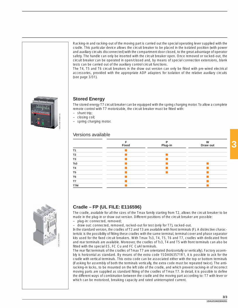
3
3/3
1SD
C21
0D15
F000
1 U
L1S
DC
210C
05F0
001
Racking-in and racking-out of the moving part is carried out the special operating lever supplied with the cradle. This particular device allows the circuit breaker to be placed in the isolated position (with power and auxiliary circuits disconnected) with the compartment door closed, to the great advantage of operator safety. The handle can only be inserted with the circuit breaker open. Once removed or racked-out, the circuit breaker can be operated in open/closed and, by means of special connection extensions, blank tests can be carried out of the auxiliary control circuit functions.The T4, T5 and T6 circuit breakers in the draw out version can only be fi tted with pre-wired electrical accessories, provided with the appropriate ADP adapters for isolation of the relative auxiliary circuits (see page 3/31).
Stored EnergyThe stored energy T7 circuit breaker can be equipped with the spring charging motor. To allow a complete remote control with T7 motorizable, the circuit breaker must be fi tted with:– shunt trip;– closing coil;– spring charging motor.
Versions available
FFixed
PPlug-in
WDraw out
T1 ■
T2 ■ ■
T3 ■ ■
Ts3 ■ ■ ■
T4 ■ ■ ■
T5 ■ ■ ■
T6 ■ ■
T7 ■ ■
T7M ■ ■
Cradle – FP (UL FILE: E116596)The cradle, available for all the sizes of the Tmax family starting from T2, allows the circuit breaker to be made in the plug-in or draw out version. Different positions of the circuit breaker are possible:– plug-in: connected, removed;– draw out: connected, removed, racked-out for test (only for T7), racked-out.In the standard version, the cradles of T2 and T3 are available with front terminals (F). A distinctive charac-teristic is the possibility of fi tting these cradles with the same terminal, terminal cover and phase separator kits used for the fi xed circuit breakers. With Tmax Ts3, T4, T5, T6 and T7, cradles with dedicated front and rear terminals are available. Moreover, the cradles of Ts3, T4 and T5 with front terminals can also be fi tted with the special ES, FC Cu and FC CuAl terminals.The rear fl at terminals of the cradles of Tmax T7 are orientated (horizontally or vertically). Factory assem-bly is horizontal as standard. By means of the extra code 1SDA063571R1, it is possible to ask for the cradle with vertical terminals. This extra code can be associated either with the top or bottom terminals (if asking for assembly of both the terminals vertically, the extra code must be repeated twice). The anti-racking-in locks, to be mounted on the left side of the cradle, and which prevent racking-in of incorrect moving parts are supplied as standard fi tting of the cradles of Tmax T7. In detail, it is possible to defi ne the different ways of combination between the cradle and the moving part according to: T7 with lever or which can be motorized, breaking capacity and rated uninterrupted current.
1SXU210023D0201

3
3/4
1SD
C21
0C07
F000
1
1SD
C21
0C09
F000
11S
DC
210C
08F0
001
T2-T3
T4-T5
1SD
C21
0D16
F000
1
Kit for conversion of plug-in cradle to draw out cradle(UL FILE: E116596)For Tmax Ts3, T4 and T5 a conversion kit is available which is made up of a guide to prepare the plug-in cradle of the circuit breaker to the draw out cradle of the circuit breaker, a racking-out crank handle and by the fl ange for the compartment door to replace the one supplied with the fi xed or plug-in circuit breaker version.
Racking-out crank handleThis allows racking-out and racking-in of the draw out circuit breaker into the cradle, with the door closed. The crank handle is the same for the whole range of circuit breakers and is automatically supplied with the cradle of draw out circuit breakers or with the conversion kit for plug-in cradles to draw out cradles.
Sliding contacts blocksThe sliding contact blocks are required for Tmax T7 in the draw out version equipped with electrical accessories or with an electronic trip unit. Their function is to realize the electrical connections of the secondary circuits between the mobile part and the cradle and these blocks work in pairs: one block is to be mounted on the mobile part and the other one on the cradle. The following table combines the types of sliding contact blocks and the electrical accessories.
Left block Central block Right block
Spring charging motor PR331 Auxiliary contacts (Q or SY)
Sping charged contact (AUX-SC) PR332 Shunt trip
Ready to close contact (AUX-RTC) Closing coil
Early auxiliary contacts (AUE) Under voltage release
Contact for signalling trip coil release trip (AUX-SA)
Trip reset
If at least one of the electrical accessories listed in the previous table is fi tted on the circuit breaker the respective pair of blocks must be mounted on the mobile part and on the cradle.
Kit for conversion into moving part of plug-in for T2 - T3 - Ts3 - T4 - T5(UL FILE: E116596)Allows the fi xed circuit breaker with front terminals to be converted into the moving part of a plug-in circuit breaker. The kit consists of:– isolating contacts– anti-racking out safety device– assembly screws and nuts– low terminal covers for the moving part.The cradle for plug-in version is necessary to complete the circuit breaker.
AccessoriesVersions and types
1SD
C21
0C06
F000
1
1SXU210023D0201

3
3/5
1SD
C21
0C10
F000
1
T4-T5-T6
T7
1SD
C21
0D17
F000
1
Kit for conversion into moving part of draw out for Ts3 - T4 - T5 - T6 - T7 (UL FILE: E116596)Allows the fi xed circuit breaker with front terminals to be converted into the moving part of a draw out circuit breaker. The kit consists of:– isolating contacts– frame– assembly screws and nuts– low terminal covers for the moving part.The circuit breakers in the draw out version must always be completed either with the front for lever op-erating mechanism (standard supply for circuit breakers fi tted with accessories in the factory, excluding T7), rotary handle operating mechanism or motor operator. The cradle for draw out version is necessary to complete the circuit breaker.
Kit for conversion of cradle into draw out for RC222 and RC223 residual current releases (IEC only)With the dedicated conversion kit, the RC222 and RC223 residual current releases for T4 and T5 also can be converted from the fi xed to the plug-in version. The kit consists of four copper busbars which make the connection between the terminals of the residual current relay and the isolating contacts mounted on the circuit breaker terminals.Therefore, to obtain a circuit breaker fi tted with the residual current release accessory in the plug-in ver-sion, the two kits for conversion of circuit breakers and for residual current release must be ordered.The power circuit is connected to the connection terminals of the cradle.
Kit for conversion of plug-in into draw out for RC222 and RC223 residual current releases (IEC only)The RC222 and RC223 residual current releases for T4 and T5 can be converted from the plug-in to the draw out version by adding a special kit consisting of a bellows to be applied on the front of the residual current release to allow racking-out of the circuit breaker and of the residual current release with the switchgear door closed.This kit can also be mounted on the fi xed version circuit breaker when there is the front for locks or the direct rotary handle operating mechanism, therefore widening the range of use of the residual current releases.
1SXU210023D0201
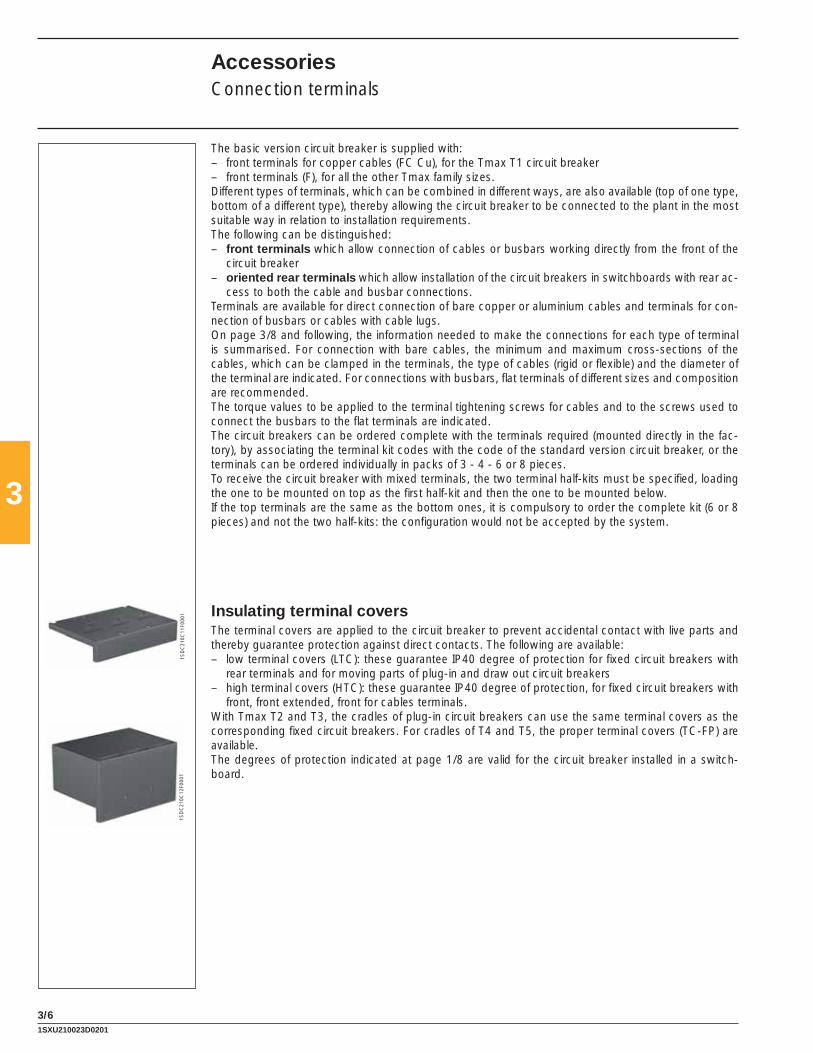
3
3/6
1SD
C21
0C11
F000
11S
DC
210C
12F0
001
AccessoriesConnection terminals
The basic version circuit breaker is supplied with:– front terminals for copper cables (FC Cu), for the Tmax T1 circuit breaker– front terminals (F), for all the other Tmax family sizes.Different types of terminals, which can be combined in different ways, are also available (top of one type, bottom of a different type), thereby allowing the circuit breaker to be connected to the plant in the most suitable way in relation to installation requirements.The following can be distinguished:– front terminals which allow connection of cables or busbars working directly from the front of the
circuit breaker– oriented rear terminals which allow installation of the circuit breakers in switchboards with rear ac-
cess to both the cable and busbar connections.Terminals are available for direct connection of bare copper or aluminium cables and terminals for con-nection of busbars or cables with cable lugs.On page 3/8 and following, the information needed to make the connections for each type of terminal is summarised. For connection with bare cables, the minimum and maximum cross-sections of the cables, which can be clamped in the terminals, the type of cables (rigid or fl exible) and the diameter of the terminal are indicated. For connections with busbars, fl at terminals of different sizes and composition are recommended.The torque values to be applied to the terminal tightening screws for cables and to the screws used to connect the busbars to the fl at terminals are indicated.The circuit breakers can be ordered complete with the terminals required (mounted directly in the fac-tory), by associating the terminal kit codes with the code of the standard version circuit breaker, or the terminals can be ordered individually in packs of 3 - 4 - 6 or 8 pieces.To receive the circuit breaker with mixed terminals, the two terminal half-kits must be specifi ed, loading the one to be mounted on top as the fi rst half-kit and then the one to be mounted below.If the top terminals are the same as the bottom ones, it is compulsory to order the complete kit (6 or 8 pieces) and not the two half-kits: the confi guration would not be accepted by the system.
Insulating terminal coversThe terminal covers are applied to the circuit breaker to prevent accidental contact with live parts and thereby guarantee protection against direct contacts. The following are available:– low terminal covers (LTC): these guarantee IP40 degree of protection for fi xed circuit breakers with
rear terminals and for moving parts of plug-in and draw out circuit breakers– high terminal covers (HTC): these guarantee IP40 degree of protection, for fi xed circuit breakers with
front, front extended, front for cables terminals.With Tmax T2 and T3, the cradles of plug-in circuit breakers can use the same terminal covers as the corresponding fi xed circuit breakers. For cradles of T4 and T5, the proper terminal covers (TC-FP) are available.The degrees of protection indicated at page 1/8 are valid for the circuit breaker installed in a switch-board.
1SXU210023D0201

3
3/7
1SD
C21
0C14
F000
1
1SD
C21
0C13
F000
1
1SD
C21
0C15
F000
1
Phase separatorsThese allow increased insulation characteristics between the phases at the connections. They are mounted from the front, even with the circuit breaker already installed, inserting them into the corresponding slots and they are available in two versions:– 3.94” (100 mm) high– 7.87” (200 mm) high.The H = 3.94” (100 mm) phase separators are supplied as obligatory with front extended type terminals (EF), whereas the ones with height 7.87” (200 mm) are obligatory with front extended spread type ter-minals (ES).The phase separating partitions are incompatible with both the high and low insulating terminal covers; while with Ts3 circuit breakers, phase separating partitions are always supplied with low terminal covers.The cradles can use the same phase separating partitions as the corresponding fi xed circuit breakers. With the phase separating partitions mounted, on request, with Tmax T1, T2 and T3 a special kit is avail-able to reach IP40 degree of protection from the front of the circuit breaker. It is possible to mount the phase separating partitions between two circuit breakers or cradles side by side.
Screws for sealing the terminal coversThese are applied to the terminal covers of fi xed circuit breakers or to the moving parts of plug-in or draw out circuit breakers. They prevent removal of both the high and low terminal covers and can be locked with a wire and lead seal.
Kit for taking up the auxiliary power supplySpecial kits are available with the fi xed version of Tmax T2, T3, T4 and T5 circuit breakers for taking up the auxiliary power supply directly from the connection terminals. They can only be combined with the front terminals for copper cables (FC Cu) for T2, T3 and T4 or with the front terminals (F) for T4-T5.
1SXU210023D0201

3
3/8
AccessoriesConnection terminals
Circuit breaker
F EF ES FC Cu FC CuAl(1) MC RC CuAl HR VRHR for
RC221/222R
Frontterminals
Frontextendedterminals
Frontextended
spreadterminals
Frontterminals for copper
cables
Frontterminalsfor CuAlcables
Multi-cableterminals
Rear terminals for CuAl cables
Rearfl at
horizontalterminals
Rearfl at
verticalterminals
Rearfl at
horizontalterminals
Rearterminals
T1 F F(2) F F F
T2 F(2) F F F F F
T3 F(2) F F F F F
Ts3 F(2) F F F F F F
T4 F(2) F F F F F F
T5 F(2) F F F F F
T6 F(2) F F F F F
T7 F(2) F F F F F F
(1) UL listed(2) Standard supplyF = Fixed
Cradle
F EF ES FC Cu FC CuAl(1) R RS HR VR HR/VR RC
Frontterminals
Frontextendedterminals
Frontextended
spreadterminals
Frontterminals for copper
cables
Frontterminalsfor CuAlcables
Rearterminals
Rear spreadedterminals
Rearfl at
horizontalterminals
Rearfl at
verticalterminals
Rearfl at
terminals
Rear terminalsfor CuAlcables
T2 P(2) P P P P P
T3 P(2) P P P P P
Ts3 P-W P-W(1) P-W
T4 P-W P-W P-W P-W P-W
T5 P-W P(3)-W(3) P-W P-W P-W P-W
T6 W W W(1)
T7 W W W W(1)
(1) UL listed(2) Standard supply(3) For T5 600 onlyP = Plug-inW = Draw out
Connection terminals
1SXU210023D0201

3
3/9
1SD
C21
0C27
F000
1 U
L
1SD
C21
0C28
F000
1
1SD
C21
0C30
F000
1 U
L
1SD
C21
0C31
F000
1 U
L
Front terminals - F
Allow connection of busbars or cables with ring terminals
1SD
C21
0C26
F000
1
Type Version Pieces Busbars/cable terminal [in-mm] Tightening [Ibin-Nm]
Terminal covers Phase separators
W H D Ø high low cradle
T2 F-P 1 0.79-20 0.30-7.5 0.20-5 0.26-6.5 54-6 R R – R
T3 F-P 1 0.94-24 0.37-9.5 0.31-8 0.33-8.5 71-8 R R – R
Ts3 150 F 1 0.79-20 0.39-10 0.16-4 0.35-9 80-9 R R – R*
Ts3 225 F 1 0.79-20 0.39-10 0.24-6 0.35-9 80-9 R R – R*
T4 F 1 0.98-25 0.37-9.5 0.31-8 0.33-8.5 161-18 R R – R
T5 F 1 1.38-35 0.43-11 0.39-10(1) 0.41-10.5 252-28 R R – R
T6 F 2 1.97-50 0.47-12 0.20-5 2x0.28-2x7 80-9 R R – R
T7 F 2 1.97-50 0.79-20 0.31-8 2x0.43-2x11 161-18 – R – R
(1) minimum 0.19”-5 mm
A = Tightening the terminal onto the circuit breakerB = Tightening the cable/busbar onto the terminalR = On requestR* = Are supplied with low terminal covers (which are, in turn, on request)S = StandardPieces = Number of busbars, cables or cable terminals
Front extended terminals - EF
Allow connection of busbars or cables with ring terminals
1SD
C21
0C29
F000
1
Type Version Pieces Busbars [in-mm]
Cable terminal [in-mm]
Tightening [Ibin-Nm]
Terminal covers
Phase separators
W D Ø W Ø A B(1) high low cradle
T1 F 1 0.59-15 0.20-5 0.33-8.5 0.59-15 0.33-8.5 63-7 80-9 R – – S
T2 F-P 1 0.79-20 0.16-4 0.33-8.5 0.79-20 0.33-8.5 54-6 80-9 R – – S
T3 F-P 1 0.79-20 0.24-6 0.39-10 0.79-20 0.39-10 71-8 161-18 R – – S
Ts3 150 F 1 0.79-20 0.16-4 0.33-8.5 0.79-20 0.31-8 80-9 80-9 R R R R*
Ts3 225 F-P-W 1 0.79-20 0.24-6 0.33-8.5 0.79-20 0.33-8.5 80-9 80-9 R R R R*
T4 F 1 0.79-20 0.39-10 0.39-10 0.79-20 0.39-10 161-18 161-18 R – – S
P-W 1 0.79-20 0.39-10 0.31-8 0.79-20 0.31-8 – 80-9 – – R R
T5 F 2 1.18-30 0.28-7 0.43-11 1.18-30 0.43-11 252-28 161-18 R – – S
P-W 2 1.18-30 0.59-15 0.39-10 1.18-30 0.39-10 – 161-18 – – R R
T6 F-W 2 1.97-50 0.20-5 0.55-14 1.97-50 0.55-14 80-9 268-30 – R R R
T7 F-W 2 1.97-50 0.39-10 4x0.43-4x11(2) – – 161-18(3) 355-40(4) – R – S
(1) class 4.8 screws (not supplied) (3) 12 Nm onto cradle of draw out circuit breaker(2) only use two holes diagonally (4) class 8.8 screws (not supplied)
1SXU210023D0201

3
3/10
1SD
C21
0C33
F000
1 U
L
1SD
C21
0C34
F000
1 U
L
1SD
C21
0C36
F000
1 U
L
1SD
C21
0C37
F000
1 U
L
Front extended spread terminals - ES
Allow connection of busbars or cables terminated with cable terminal
1SD
C21
0C32
F000
1
Type Version Pieces Busbars [in-mm]
Cable terminal [in-mm]
Tightening [Ibin-Nm]
Terminal covers
Phase separators
W D Ø W Ø A B(1) high low cradle
T2 F-P 1 1.18-30 0.16-4 0.41-10.5 1.18-30 0.41-10.5 54-6 161-18 – – – S
T3 F-P 1 1.18-30 0.16-4 0.41-10.5 1.18-30 0.41-10.5 71-8 161-18 – – – S
Ts3 F 1 1.18-30 0.16-4 0.33-8.5 1.18-30 0.33-8.5 80-9 80-9 – S – S*
T4 F 1 1.18-30 0.24-6 0.41-10.5 1.18-30 0.41-10.5 161-18 161-18 – – – S
T5 F-P(2)-W(2) 1 1.58-40 0.39-10 0.43-11 0.43-11 0.43-11 252-28 161-18 – – – S
T6 F 1 3.15-80 0.20-5 3x-0.51-3x13 3x1.77-3x45 0.51-13 80-9 268-30 – – – –
T7 F 2 1.97-50 0.39-10 3x-0.51-3x13 4x1.77-4x45 0.51-13 161-18 355-40 – – – S
(1) class 4.8 screws (not supplied) (2) for T5 600 only
Front terminals for copper cables - FC Cu
Allow connection of bare copper cables directly to the circuit breaker
1SD
C21
0C35
F000
1
Type Assembly Version Pieces Cable [AWG or Kcmil-mm2]
Flexible busbars
Tightening [Ibin - Nm]
Ø [in-mm]
Terminal covers
Phase separators
rigid fl exible W x S x N(2) A B high low cradle
T1/T1 1p standard F 1 2.5…70 2.5…50 9 x 0.8 x 6 – 63-7 0.47-12 R R – R
standard F 2 – 2.5…35 – – 63-7 0.47-12 R R – R
T2 standard F-P 1 1…95 1…70 13 x 0.5 x 10 – 63-7 0.55-14 R R R R
standard F-P 2 – 1…50 – – 63-7 0.55-14 R R R R
T3 standard F-P 1 6…185 6…150 15.5 x 0.8 x 10 – 89-10 0.71-18 R R R R
standard F-P 2 – 6…70 – – 89-10 0.71-18 R R R R
Ts3 standard F-P-W 1 10...350-6...185 – – – 142-16 0.71-18 R R S R*
T4 standard F-P-W 1 2.5…185 2.5…120 15.5 x 0.8 x 10 – 89-10 0.71-18 R R S R
standard F-P-W 2 – 2.5…95 – – 89-10 0.71-18 R R S R
T5 standard F-P-W 1 16…300 16…240 24 x 1 x 10 – 222-25 1.10-28 R R S R
standard F-P-W 2 – 16…150 – – 222-25 1.10-28 R R R –
external F 2 120…240 – – 18 222-25 – S – – –
(1) UL Listed (2) W = width; S = thickness; N = n. of bars
AccessoriesConnection terminals
A = Tightening the terminal onto the circuit breakerB = Tightening the cable/busbar onto the terminalR = On requestS = StandardR* = Are supplied with low terminal covers (which are, in turn, on request)S* = Are supplied as standard with the low terminal coversPieces = Number of busbars, cables or cable terminals
1SXU210023D0201

3
3/11
1SD
C21
0C42
F000
1 U
L
1SD
C21
0C43
F000
1 U
L
1SD
C21
0C45
F000
1 U
L
Front terminals for copper/aluminium cables - FC CuAl (UL listed)Allow connection of bare copper or aluminium cables directly to the circuit breaker (solid aluminium cables cannot be used)
T2-T5 Standard
1SD
C21
0C40
F000
1
T4-T5 External
1SD
C21
0C41
F000
1
Type Assembly Version Pieces Cable [AWG or Kcmil-mm2]
Tightening [Ibin-Nm]
Ø [in-mm]
Terminal covers
Phase separators
rigid A B high low cradle
T1 1P/T1 standard F 1 14…10-2.5…6 20-2.5 – 0.37-9.5 R R – R
8.0-10 40-4.5 – – – – – –
6…1/0-16…50 45-5 – – – – – –
T2 100 standard F-P 1 14…1/0-2.5…50 80-9 50-5.6 – R R R R
T3 100 standard F-P 1 14…1/0-2.5…50 80-9 50-5.6 0.39-10 R R R R
T3 225 standard F-P 1 4…300-25…150 80-9 200-22.6 0.67-17 R R R R
Ts3-D 150 (In=100) standard F 1 14…1/0-2.5…50 80-9 50-5.6 – R – – –
Ts3 150 standard F 1 2…4/0-35…95 80-9 120-13.5 0.56-14.2 R – – –
Ts3 225 standard F 1 4…300-25…150 80-9 276-31 – R – – –
T4 250 standard F-P-W 1 6…350-6…185 274-31 80-9 0.7-18 R R S R
T4 250 standard F 1 14…1/0-2.5…50 50-5.6 80-9 0.39-9.9 R R – R
T5 400 external F 2 3/0…250-95…120 274-31 159-18 0.61-15.5 S – – R
T5 400 standard F-P-W 1 250…500-120…240 380-43 159-18 0.84-21.5 R R S R
T5 600 external F 2 3/0…500-95…240 274-31 159-18 0.84-21.5 S – – R
T6 600 standard F 2 250…500-120…240 44-5 276-31 0.87-22 S – – –
T6 800 standard F 2 250…500-120…240 44-5 276-31 0.87-22 S – – –
T7 1200 external F 4 2/0…500-70…240 160-18 380-43 0.84-21.5 S – – –
Multi-cable terminals - MC
Allow connection of cables directly to the circuit breaker
1SD
C21
0C44
F000
1
Type Version Pieces Cable [AWG or Kcmil-mm2] Tightening [Ibin-Nm] Terminal covers Phase separators
max fl exible rigid A B high low cradle
T4 F 6 2.5…25 2.5…35 161-18 63-7 S – – –
T5 F 6 – 16…50 161-18 45-5 S – – –
A = Tightening the terminal onto the circuit breakerB = Tightening the cable/busbar onto the terminalR = On requestS = StandardPieces = Number of busbars, cables or cable terminals
1SXU210023D0201

3
3/12
A = Tightening the terminal onto the circuit breakerB = Tightening the cable/busbar onto the terminalR = On requestS = StandardPieces = Number of busbars, cables or cable terminals
Rear terminals for copper/aluminium cables - RC CuAlAllow connection of bare copper or aluminium cables directly to the circuit breaker
1SD
C21
0C46
F000
1
1SD
C21
0C46
F000
1
Type Version Pieces Cable [AWG or Kcmil-mm2] Tightening [Ibin-Nm] Ø [in-mm] Terminal covers
rigid A B high low
Ts3 F 1 4…250-25…120 80-9 276-31 0.63-16 S –
T6 600 F 2 250…500-120…240 80-9 383-43 0.69-17.5 S –
T6 800 F 3 2/0…350-70…185 80-9 276-31 0.69-17.5 S –
Rear fl at horizontal terminals - HRAllow connection of busbars or cable terminal at the rear. They can only be installed horizontally.
T1 1SD
C21
0C47
F000
1
Type Version Pieces Busbars [in-mm] Cable terminal [in-mm] Tightening [Ibin-Nm] Terminal covers PhaseseparatorsW D Ø W Ø A B(1) high low
T1 F 1 0.55-14 0.20-5 0.24-6.2 0.55-14 0.24-6.2 63-7 44-5 – S –
T7 F 2 1.97-50 0.39-10 2x0.43-2x11 – – 179-20 355-40 – S –
(1) class 8.8 screws (not supplied)
Rear fl at vertical terminals - VRAllow connection of busbars or cable terminal at the rear. They can only be installed vertically.
Type Version Pieces Busbars [in-mm] Cable terminal [in-mm] Tightening [Ibin-Nm] Terminal covers PhaseseparatorsW D Ø W Ø A B(1) high low
T7 F 2 1.97-50 0.31-8 2x0.43-2x11 – – 179-20 355-40 – S –(1) class 8.8 screws (not supplied)
AccessoriesConnection terminals
1SXU210023D0201

3
3/13
1SD
C21
0C50
F000
1 U
L
Rear terminals - R
Allow connection of busbars or cable terminal at the rear. They can be installed in 4 different positions to facilitate connection to cable/busbars
1SD
C21
0C49
F000
1
Type Version Pieces Busbars [in-mm] Tightening [Ibin-Nm] Terminal covers Phase separators
W D Ø A B(1) high low
T2 F-P 1 0.79-20 0.16-4 0.33-8.5 54-6 80-9 – S –
T3 F-P 1 0.79-20 0.24-6 0.33-8.5 54-6 80-9 – S –
Ts3 150 F 1 0.79-20 0.16-4 0.49-12.5 89-10 179-20 – S S*
P-W 1 0.79-20 0.16-4 0.49-12.5 89-10 179-20 – – –
Ts3 225 F 1 0.79-20 0.24-6 0.49-12.5 89-10 179-20 – S S*
P-W 1 0.79-20 0.24-6 0.49-12.5 89-10 179-20 – – –
T4 F 1 0.79-20 0.39-10 0.33-8.5 54-6 80-9 – S –
T5 F 2 1.18-30 0.28-7 0.43-11 161-18 161-18 – S –
T6 F 2 1.97-50 0.20-5 0.55-14 161-18 268-30 – S –
T7 F 2 1.97-50 0.31-8 2x0.43-2x11 179-20 355-40 – S –
(1) class 8.8 screws (not supplied)
Rear fl at horizontal terminals for RC221/RC222 - HR
Allow connection of busbars or cable terminal at the rear with RC221/RC222. They can be installed horizontally
1SD
C21
0C48
F000
1
Type Version Pieces Busbars [in-mm] Tightening [Ibin-Nm] Terminal covers Phase separators
W D Ø A B high low
T1 F 1 0.55-14 0.20-5 0.24-6.2 63-7 44-5(1) – – –
(1) class 8.8 screws (not supplied)
A = Tightening the terminal onto the circuit breakerB = Tightening the cable/busbar onto the terminalR = On requestS = StandardS* = Are supplied as standard with the low terminal coversPieces = Number of busbars, cables or cable terminals
1SXU210023D0201

3
3/14
1SD
H00
0529
R08
10
Rear fl at horizontal and vertical terminals for cradles - HR/VR
These allow connection of busbars or cable terminals at the rear. There are rear horizontal or vertical terminals.
1SD
C21
0C51
F000
1
Type Version Pieces Busbars [in-mm] Cable terminal [in-mm] Tightening [Ibin-Nm] Terminal covers PhaseseparatorsW D Ø W Ø A B(1) high low cradle
T4 P - W 1 0.79-20 0.39-10 0.39-10 0.79-20 0.39-10 – 159-18 – – – –
T5 400 P - W 1 0.98-25 0.39-10 0.47-12 0.98-25 0.47-12 – 159-18 – – – –
T5 600 P - W 2 1.57-40 0.59-15 0.43-11 1.57-40 0.43-11 – 159-18 – – – –
T6 W 2 1.97-50 0.20-5 0.55-14 1.97-50 0.55-14 – 268-30 – – – –
T7 W 2 1.97-50 0.39-10 2x0.43-2x11 – – 106-12 355-40 – – – –
(1) class 4.8 screws (not supplied) (2) for vertical assembly directly in the factory, use extra code 1SDA063571R1
A = Tightening the terminal onto the circuit breakerB = Tightening the cable/busbar onto the terminalR = On requestS = StandardPieces = Number of busbars, cables or cable terminals
Rear spreaded terminals - RS
Allow connection of busbars and cable terminal at the rear.
Type Version Pieces Busbars [in-mm] Tightening [Ibin-Nm] Terminal covers Phase separators
W D Ø A B high low cradle
T7 W 2 2.36-60 0.39-10 2 x 11 161-18 355-40 – – – –
AccessoriesConnection terminals
Rear terminals for CuAl cables - RC (UL LISTED)
Type Version Pieces Cable terminal [in-mm] Tightening [Ibin-Nm] Terminal covers Phase separators
W Ø A B high low cradle
T7 W 1 1.38-35 0.55-14 425-48 355-40 – – – –
1SXU210023D0201

3
3/15
1SD
C21
0C52
F000
11S
DC
210C
53F0
001
T1-T2-T3
1SD
C21
0C54
F000
1
1SD
C21
0C55
F000
1
T1-T2-T3 T4-T5-T6
T4-T5-T6
T7
1SD
C21
0D18
F000
1
1SD
C21
0C00
F000
1
Ts3
The Tmax family of circuit breakers can be fi tted with service releases (shunt trip, closing coil and un-dervoltage release). These are available in the pre-cabled version, depending on the size of the circuit breaker fi tted with 39.4” (1 m) long free cables, with a connector with 39.4” (1 m) cables or with a simple pin connector and two terminals to be mounted in the terminal board. Assembly is carried out for all the releases by pressing into the special seat in the left part of the circuit breaker (right for T7) and fi xing with the screw provided. The releases are interchangeable for T1, T2, T3, Ts3 (both for the three-pole and four-pole version), whereas for T4, T5 and T6 in the four-pole version the shunt trip (not possible with PS-SOR) and the undervoltage release can be housed at the same time, as long as they are in the wired version and the shunt trip is necessarily mounted in the slot of the third pole. T4, T5, T6 circuit breakers in the draw out version can only be equipped with pre-cabled accessories; the T4-T5-T6 circuit breakers complete with motorized controls can only be fi tted with prewired undervoltage and shunt trips.The T7 circuit breaker allows simultaneous mounting of all three service releases. These two possibilities are available on the three-pole version as well. Moreover Tmax T7 can be equipped with two shunt trips instead of the undervoltage release to facilitate some specifi c applications where a very high safety level of the remote circuit breaker opening command is required.
Shunt trip – SOR (UL FILE: E116596)Allows circuit breaker opening by means of an electric command. Operation of the trip is provided for a voltage between 70% and 110% of the rated power supply voltage value Un, both in alternating current and in direct current. For Tmax T1, T2, T3, T4, T5 and T6, the SOR shunt trip is fi tted with a limit contact for cutting off the power supply in the open position and with the release tripped.
AccessoriesService releases
1SXU210023D0201
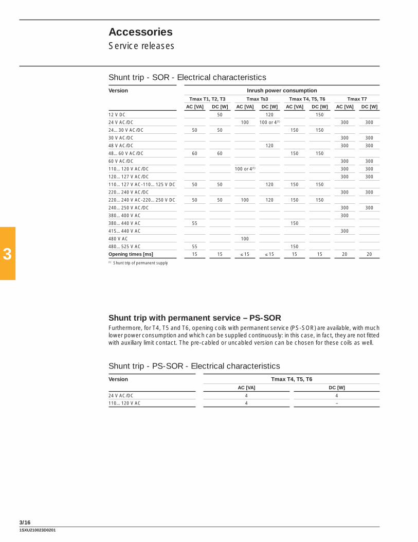
3
3/16
Shunt trip with permanent service – PS-SORFurthermore, for T4, T5 and T6, opening coils with permanent service (PS-SOR) are available, with much lower power consumption and which can be supplied continuously: in this case, in fact, they are not fi tted with auxiliary limit contact. The pre-cabled or uncabled version can be chosen for these coils as well.
Shunt trip - PS-SOR - Electrical characteristics
Version Tmax T4, T5, T6
AC [VA] DC [W]
24 V AC/DC 4 4
110…120 V AC 4 –
AccessoriesService releases
Shunt trip - SOR - Electrical characteristics
Version Inrush power consumption
Tmax T1, T2, T3 Tmax Ts3 Tmax T4, T5, T6 Tmax T7
AC [VA] DC [W] AC [VA] DC [W] AC [VA] DC [W] AC [VA] DC [W]
12 V DC 50 120 150
24 V AC/DC 100 100 or 4(1) 300 300
24…30 V AC/DC 50 50 150 150
30 V AC/DC 300 300
48 V AC/DC 120 300 300
48…60 V AC/DC 60 60 150 150
60 V AC/DC 300 300
110…120 V AC/DC 100 or 4(1) 300 300
120…127 V AC/DC 300 300
110…127 V AC-110…125 V DC 50 50 120 150 150
220…240 V AC/DC 300 300
220…240 V AC-220…250 V DC 50 50 100 120 150 150
240…250 V AC/DC 300 300
380…400 V AC 300
380…440 V AC 55 150
415…440 V AC 300
480 V AC 100
480…525 V AC 55 150
Opening times [ms] 15 15 ≤ 15 ≤ 15 15 15 20 20
(1) Shunt trip of permanent supply
1SXU210023D0201

3
3/17
1SD
C21
0C56
F000
1
T7
1SD
C21
0D18
F000
1
Shunt trip Test Unit – SOR Test UnitThe SOR Test Unit - control/monitoring unit - allows correct operation of the shunt trips which can be mounted on the Tmax T7 circuit breaker to be verifi ed, to guarantee a high level of reliability for the circuit breaker opening command.The SOR Test Unit - control/monitoring unit - allows continuity of the shunt trips with a rated service voltage between 24 V and 250 V (AC and DC) to be verifi ed, as well as operation of the electronic circuit of the opening coil. The continuity check is carried out cyclically at an interval of 20 seconds between one test and the next. The unit has LED optic signals on the front which provide the following information:– POWER ON: presence of power supply– YO TESTING: test being carried out– TEST FAILED: indication following a failed test or lack of auxiliary power supply– ALARM: signalling after three failed tests.There are also two relays and a changeover switch available on board the unit which allow the following two events to be signalled remotely:– failure of a test (resetting takes place automatically when the alarm goes off)– failure of three tests (resetting only takes place by means of the manual RESET from the front of the
unit).
Characteristics
Auxiliary power supply 24 V…250 V AC / DC
Maximum interrupted current 6 A
Maximum interrupted voltage 250 V AC
Closing coil – SCRThe closing coil - only available on the motorizable versions of Tmax T7 - allows remote closure of the circuit breaker when the circuit breaker closing springs are charged. The technical characteristics and the service voltages of the closing coil are identical to those of the shunt trip available on T7. The closing time of the circuit breaker by means of SCR is 80 ms.
1SXU210023D0201
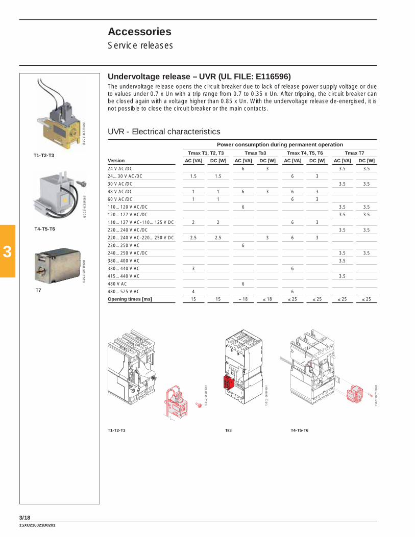
3
3/18
1SD
C21
0C58
F000
1
1SD
C21
0C55
F000
1
T1-T2-T3 T4-T5-T6
1SD
C21
0C57
F000
11S
DC
210C
53F0
001
T1-T2-T3
T4-T5-T6
T7
1SD
C21
0D18
F000
1
1SD
C21
068B
F000
1
Ts3
Undervoltage release – UVR (UL FILE: E116596)The undervoltage release opens the circuit breaker due to lack of release power supply voltage or due to values under 0.7 x Un with a trip range from 0.7 to 0.35 x Un. After tripping, the circuit breaker can be closed again with a voltage higher than 0.85 x Un. With the undervoltage release de-energised, it is not possible to close the circuit breaker or the main contacts.
UVR - Electrical characteristics
Power consumption during permanent operation
Tmax T1, T2, T3 Tmax Ts3 Tmax T4, T5, T6 Tmax T7
Version AC [VA] DC [W] AC [VA] DC [W] AC [VA] DC [W] AC [VA] DC [W]
24 V AC/DC 6 3 3.5 3.5
24…30 V AC/DC 1.5 1.5 6 3
30 V AC/DC 3.5 3.5
48 V AC/DC 1 1 6 3 6 3
60 V AC/DC 1 1 6 3
110…120 V AC/DC 6 3.5 3.5
120…127 V AC/DC 3.5 3.5
110…127 V AC-110…125 V DC 2 2 6 3
220…240 V AC/DC 3.5 3.5
220…240 V AC-220…250 V DC 2.5 2.5 3 6 3
220…250 V AC 6
240…250 V AC/DC 3.5 3.5
380…400 V AC 3.5
380…440 V AC 3 6
415…440 V AC 3.5
480 V AC 6
480…525 V AC 4 6
Opening times [ms] 15 15 − 18 ≤ 18 ≤ 25 ≤ 25 ≤ 25 ≤ 25
AccessoriesService releases
1SXU210023D0201
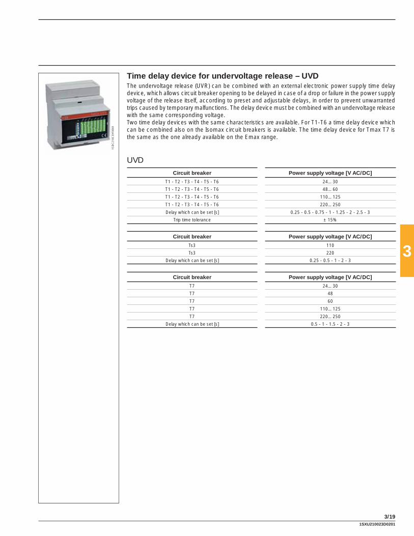
3
3/19
1SD
C21
0C59
F000
1
Time delay device for undervoltage release – UVDThe undervoltage release (UVR) can be combined with an external electronic power supply time delay device, which allows circuit breaker opening to be delayed in case of a drop or failure in the power supply voltage of the release itself, according to preset and adjustable delays, in order to prevent unwarranted trips caused by temporary malfunctions. The delay device must be combined with an undervoltage release with the same corresponding voltage. Two time delay devices with the same characteristics are available. For T1-T6 a time delay device which can be combined also on the Isomax circuit breakers is available. The time delay device for Tmax T7 is the same as the one already available on the Emax range.
UVD
Circuit breaker Power supply voltage [V AC/DC]
T1 - T2 - T3 - T4 - T5 - T6 24…30
T1 - T2 - T3 - T4 - T5 - T6 48…60
T1 - T2 - T3 - T4 - T5 - T6 110…125
T1 - T2 - T3 - T4 - T5 - T6 220…250
Delay which can be set [s] 0.25 - 0.5 - 0.75 - 1 - 1.25 - 2 - 2.5 - 3
Trip time tolerance ± 15%
Circuit breaker Power supply voltage [V AC/DC]
Ts3 110
Ts3 220
Delay which can be set [s] 0.25 - 0.5 - 1 - 2 - 3
Circuit breaker Power supply voltage [V AC/DC]
T7 24…30
T7 48
T7 60
T7 110…125
T7 220…250
Delay which can be set [s] 0.5 - 1 - 1.5 - 2 - 3
1SXU210023D0201

3
3/20
1SD
C21
0C61
F000
1
1SD
C21
0C60
F000
1
Connectors for service releases (only for Ts3)These allow the shunt trip or undervoltage release to be connected to the power supply circuit. They are available in the following versions:– for fi xed circuit breakers– for plug-in/draw out circuit breakers.Assembly is by means of pressure into special slots in the left side of the circuit breaker.Cables of different lengths (UL/CSA) are available.Socket-plugs with 3, 6 or 12 poles and cable kit (UL/CSA) with a length of 78.8” (2 m) are available for Tmax: the socket-plugs are necessary only for plug-in version.
AccessoriesService releases
1SD
C21
0540
F000
3
1SD
C21
0618
F000
3
1SD
C21
0619
F000
3
Testing extension for service releasesAvailable for Tmax Ts3, T4, T5 and T6, this allows the service releases to be supplied with the circuit breaker in the removed position. With the circuit breaker in safe conditions, i.e. isolated from the power circuits, this makes it possible to carry out blank tests of the circuit breaker functionality.
1SXU210023D0201

3
3/21
1SD
C21
0C62
F000
11S
DC
210C
63F0
001
AUX - 250 V AC/DC
AUX-C - 250 V AC/DC
T7
1SD
C21
0D19
F000
1
These allow information on the operating state of the circuit breaker to be real outside.Installation of these accessories is carried out directly from the front of the circuit breaker in special slots placed on the right-hand side of the circuit breaker, completely segregated from the live parts - all to the benefi t of user safety. The auxiliary contacts can be supplied (depending on the type) either with cabling directly on the circuit breaker terminal board or in the pre-cabled version, depending on the size of the circuit breaker fi tted with free cables 39.4” (1 m) long, with a connector with 39.4” (1 m) long cables. The pre-cabled version is mandatory on the T4, T5 and T6 circuit breakers in the draw out version. The auxiliary contacts for T7 are always fi tted with three terminals to be mounted in the terminal board to carry out the cabling. The auxiliary contacts are available for use both in direct and alternating current at various voltages. The signals are reset when the circuit breaker is reset.
T1-T7 (AUX)Available both in the pre-cabled and uncabled version, auxiliary contacts supply the following electrical signalling:– Form C (open/closed): indicates the position of the circuit breaker contacts (Q)– Bell alarm: signals circuit breaker opening due to overcurrent release trip (for overload or short circuit),
trip of the residual current release, of the opening coil or of the undervoltage release, of the emergency opening pushbutton of the motor operator or two to operation of the test pushbutton (SY)
– Contact for signalling electronic trip unit tripped: signals intervention of one of the protection functions of the electronic trip unit (S51) (except for Ts3).
The auxiliary contacts for T7 are always fi tted with terminals to be mounted in the terminal box to carry out wiring.
T4, T5, T6 and T7 with electronic trip units (AUX-SA) There is a contact for signalling electronic trip units tripped, only available in the pre-cabled version for use at 250 V AC.
T4, T5 and T6 (AUX-MO)This auxiliary contact, only in the uncabled version, must be combined with the motor operator and indicates the motor operation mode (manual or remote).
T7 (AUX-RTC)The “circuit breaker ready to close” auxiliary contact is available with wiring directly on the terminal box of the stored energy T7 circuit breaker and signals that the circuit breaker is ready to accept a closing command if there are the following fi ve conditions:– circuit breaker open– closing springs charged– any opening coil de-energised– any undervoltage coil energised– opening solenoid armed.
T7 (AUX-SC)Remotely indicates the state of the circuit breaker operating mechanism is closing springs (supplied only with the spring charging motor).
AccessoriesElectrical signals
1SXU210023D0201

3
3/22
AUX AUX-C
1SD
C21
0C64
F000
1
1SD
C21
0C64
F000
1
AccessoriesElectrical signals
T4, T5 and T6 with PR222DS/PD-A and electronic trip unit (AUX-E)Only available in the pre-cabled version, the auxiliary contacts AUX-E (also called electronic version con-tacts) communicate the state of the circuit breaker to the electronic trip unit and make an open/closed signal available to the outside and another one for electronic trip unit tripped.They can only be combined with the PR222DS/PD-A electronic trip unit and only function when there is a 24 V DC auxiliary power supply to the trip unit for the communication functions.The AUX-E contacts can, moreover, be directly connected to the MOE-E motor operator (see page 3/29).The “traditional” version of the auxiliary contacts can also be combined with the protection trip units with dialogue; in this case, only electrical signalling of the state of the circuit breaker will be provided and it will not be possible to communicate remotely or control the motor.
1SXU210023D0201

3
3/23
AUX - Electrical characteristics
AUX 250 V - T1...T6
Power supply voltage Service currentCategory of utilisation (IEC 60947-5-1)
AC 14 DC 13125 V 6 A 0.3 A250 V 5 A 0.15 AProtection with gG 10x38 type fuse (Imax 6 A)
Table of the possible combinations of the T7-T7M auxiliary contacts
T7 SY Q1 1Q + 1SY T7M Q2 Q3 2Q
Q2 Q3 2Q Q4 Q1 2Q
SY Q1 Q2 Q3 3Q + 1SY Q4 Q1 Q2 Q3 4Q
AUX 400 V - Ts3
Power supply voltage Breaking capacityAC (50-60) [V] DC [V] Ohmic Load [A]
125 0.3250 0.15
250 6400 3
AUX 400 V - T4...T7
Power supply voltage Service current In [A]AC DC
125 V – 0.5250 V 12(1) 0.3400 V 3 –(1) 5 A for Tmax T7
AUX 24 V - T1...T7
Power supply voltage Service current In [A]AC DC
24 V – ≥ 0.75 mA5 V – ≥ 1 mA
AUX-E - T4...T6
Typical contact MosfetVmax 350 V DC/230 V ACImax 50 mA AC/DCPmax (resistive load) 17 W, 11 VASystem contact/ground insulation 2000 V AC (1 min. @ 50 Hz)Contact/contact insulation 400 V DC
1SXU210023D0201
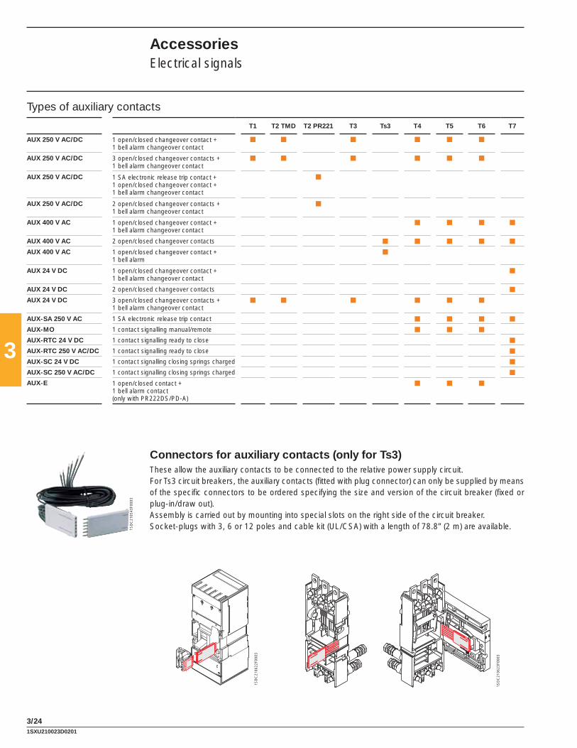
3
3/24
Types of auxiliary contacts
T1 T2 TMD T2 PR221 T3 Ts3 T4 T5 T6 T7
AUX 250 V AC/DC 1 open/closed changeover contact + 1 bell alarm changeover contact
■ ■ ■ ■ ■ ■
AUX 250 V AC/DC 3 open/closed changeover contacts +1 bell alarm changeover contact
■ ■ ■ ■ ■ ■
AUX 250 V AC/DC 1 SA electronic release trip contact +1 open/closed changeover contact +1 bell alarm changeover contact
■
AUX 250 V AC/DC 2 open/closed changeover contacts +1 bell alarm changeover contact
■
AUX 400 V AC 1 open/closed changeover contact +1 bell alarm changeover contact
■ ■ ■ ■
AUX 400 V AC 2 open/closed changeover contacts ■ ■ ■ ■ ■
AUX 400 V AC 1 open/closed changeover contact +1 bell alarm
■
AUX 24 V DC 1 open/closed changeover contact + 1 bell alarm changeover contact
■
AUX 24 V DC 2 open/closed changeover contacts ■
AUX 24 V DC 3 open/closed changeover contacts +1 bell alarm changeover contact
■ ■ ■ ■ ■ ■
AUX-SA 250 V AC 1 SA electronic release trip contact ■ ■ ■ ■
AUX-MO 1 contact signalling manual/remote ■ ■ ■
AUX-RTC 24 V DC 1 contact signalling ready to close ■
AUX-RTC 250 V AC/DC 1 contact signalling ready to close ■
AUX-SC 24 V DC 1 contact signalling closing springs charged ■
AUX-SC 250 V AC/DC 1 contact signalling closing springs charged ■
AUX-E 1 open/closed contact +1 bell alarm contact (only with PR222DS/PD-A)
■ ■ ■
Connectors for auxiliary contacts (only for Ts3)These allow the auxiliary contacts to be connected to the relative power supply circuit.For Ts3 circuit breakers, the auxiliary contacts (fi tted with plug connector) can only be supplied by means of the specifi c connectors to be ordered specifying the size and version of the circuit breaker (fi xed or plug-in/draw out).Assembly is carried out by mounting into special slots on the right side of the circuit breaker.Socket-plugs with 3, 6 or 12 poles and cable kit (UL/CSA) with a length of 78.8” (2 m) are available. 1S
DC
2105
43F0
003
1SD
C21
0622
F000
3
1SD
C21
0623
F000
3
AccessoriesElectrical signals
1SXU210023D0201

3
3/25
1SD
C21
0C67
F000
1
1SD
C21
0C66
F000
11S
DC
210C
60F0
001
1SD
C21
0C65
F000
1
Testing extension for auxiliary contactsAvailable for Tmax T4, T5 and T6 circuit breakers, this allows the auxiliary contacts to be connected to the relative power supply circuit with the circuit breaker in the removed position. With the circuit breaker in a safe position, i.e. isolated from to the power circuits, it is possible to carry out blank function tests of the circuit breaker.
Early auxiliary contacts – AUEEarly auxiliary contacts are normally open contacts, advanced in relation to closing (2 contacts for all the sizes, except for T7 where there are 3). They allow the undervoltage release to be supplied in advance, in relation to closing of the main contacts, in compliance with the IEC 60204-1 and VDE 0113 Standards. They are mounted inside the direct and transmitted rotary handle operating mechanism, whereas on T7 with the electric operating mechanism they are mounted directly on the circuit breaker. The early contacts are only supplied in the cabled version with 39.4” (1 m) long cables, complete with socket-plugs with 6 poles for T1, T2 and T3 or with socket-plug connectors with 39.4” (1 m) cables for T4, T5 and T6. It is necessary to bear in mind that once the connectors for T4, T5 and T6, are inserted in the special slot on the right-hand side of the circuit breaker they extend further out than the outline of the circuit breaker itself. For Ts3 the contact is supplied complete with double slide socket connectors for simultaneous connection of the undervoltage release and of the consent contact itself. The early auxiliary contacts for T7 are always fi tted with 3 terminals to be mounted in the terminal board to carry out the cabling.
1SXU210023D0201

3
3/26
1SD
C21
0C68
F000
1
1SD
C21
0C69
F000
1
1SD
C21
0C70
F000
1
T2-T3 T4-T5
T7
1SD
C21
0D20
F000
1
1SD
C21
0D22
F000
1
1SD
C21
0N78
F000
1
Auxiliary position contacts – AUPAuxiliary position contacts which provide electrical signalling of the circuit breaker position in relation to the cradle are available. The following auxiliary position contacts are available:
T2 - T3– contacts signalling circuit breaker is racked-in.
Ts3– contacts signaling circuit breakers is racked-in– contacts signaling circuit breakers is drawn-out.
T4 - T5 - T6– circuit breaker racked-in signalling contacts for plug-in and draw out versions– circuit breaker racked-out signalling contacts only for draw out version– circuit breaker racked-in signalling contacts for plug-in and draw out versions 24 V DC– circuit breaker racked-out signalling contacts only for draw out version 24 V DC.
T7– contacts for signalling circuit breaker is racked-in– contacts for signalling circuit breaker is isolated-test– contacts for signalling circuit breaker is racked-out.
A maximum of three contacts can be installed on the cradle of T2, T3, T4 and T5, a maximum of two contacts for Ts3, whereas up to fi ve auxiliary contacts can be mounted on the cradle of T6 in all the com-binations (for T4 and T5, in the draw out version, only one contact for signalling circuit breaker racked-out can be housed in the compartment closest to the bottom terminals).The auxiliary contacts for T7 are inserted in a single block consisting of two contacts for signalling racked-in, two for isolated-test and two for racked-out.
Trip resetAvailable on the motorized T7 the trip reset is a coil which allows remote circuit breaker resetting follow-ing a trip of the overcurrent releases. It is available with two power supply voltages: 24...30 V AC/DC, 110...130 V AC/DC and 200...240 V AC/DC.
Mechanical operation counterAvailable on the motorized T7, it is connected to the operating mechanism by means of a simple lever mechanism. It indicates the number of circuit breaker mechanical operations. The indication is visible from the outside on the front of the circuit breaker.
AccessoriesElectrical signals
1SXU210023D0201

3
3/27
1SD
C21
0C71
F000
11S
DC
210C
72F0
001
1SD
C21
0C73
F000
1
1SD
C21
0C74
F000
1
Rated voltage, Un
AC [V] 110…250
DC [V] 48…60 / 110…250
Operating voltage 85…110% Un
Inrush power consumption during operation 1800 [VA] / 1000 [W]
Power on stand-by < 100 [mW]
Time opening [s] < 0.1
closing [s] < 0.1
Mechanical life [no. Operations] 25000
[no. Operations/h] 240 (T1 and T2); 120 (T3)
Degree of protection, on the front IP30
Minimum control impulse time on opening and closing [ms] >100
The unit is permanently supplied on stand-by, a control is applied by means of an external contact (relay, opto-insulator) in a low power circuit.Contact characteristics: V AC/DC = 24 V I AC/DC = 50 mA
Solenoid operator for T1, T2 and T3 – MOS (UL FILE: E116596)The solenoid operator allows remote circuit breaker opening and closing control and is particularly recommended for use in electric network supervision and control systems. A selector allows switching from automatic to manual operation and a block is also available (supplied as standard) for the operat-ing mode of the motor. It is always provided with a padlock in the open position which prevents any additional commands, either locally or remotely. It operates both circuit breaker opening and closing, working directly on the circuit breaker lever.It is offered in two versions, the fi rst is “side-by-side” with the circuit breaker for T1 and T2, for installa-tion on a panel or DIN EN 50022 rail. The other on the “front” for T1, T2 and T3, suitable for installation directly on the front of the circuit breaker.The latter is complete with an operating handle. The front version can also be used with plug-in circuit breakers.Coupling with the residual current release is only allowed for a circuit breaker with a side-by-side sole-noid operator, to allow access to the user interface of the residual current release from the front of the switchgear. In fact, using the solenoid operator superimposed would imply the circuit breaker position on the rear of the door and its residual current release and the interface would no longer be accessible. This combination can only be installed directly on the back plate of the switchgear. Both versions can be used either in the three-pole or four-pole version. The solenoid operator is supplied complete with 1m long cables and, just for the superimposed version, with a socket-plug connector with 5 poles.Both the opening and closing commands are operated by the solenoid which acts directly on the circuit breaker lever. The main parameters relative to the solenoid operator are indicated in the table.
AccessoriesRemote control
1SXU210023D0201

3
3/28
1SD
C21
0547
F000
3
1SD
C21
0626
F000
3
1SD
C21
0627
F000
3
Direct action motor operator for Ts3 (UL fi le: E116596)
Both the opening and closing command is controlled by the motor, which acts directly on the circuit breaker lever. The table shows the power supply voltage values Un [V].
Motor operator Ts3
AC DC
Rated voltage, Un [V] 24
[V] 48…60
[V] 120 125
[V] 240 250
[V] 440
Operating voltage 85…110% Un
Inrush power absorption Ps 500 [VA] 500 [W]
Service power absorption Pc 350 [VA] 350 [W]
Operating frequency [Hz] 50-60
Time constant [ms] 18
Duration opening [s] 0.1
closing [s] 0.1
Mechanical life [no. operations] 15000 (S3-S4) - 10000 (S5)
Degree of protection, on the front IP30
Minimum duration of the opening and closing command impulse
[ms] ≥ 150
AccessoriesRemote control
1SXU210023D0201

3
3/29
1SD
C21
0630
F000
3
1SD
C21
0550
F000
3
Connectors for motor operators (only for Ts3)The motor operators for Ts3 can only be supplied by means of the specifi c connectors. They are of the slide type and allow simultaneous connection of both the motor operator and the auxiliary contacts to the relative power supply circuit. They are an alternative to the corresponding connectors for the auxiliary contacts because they are housed in the same seat. They must be ordered specifying the size and ver-sion of the circuit breaker (fi xed or plug-in/draw out).
1SXU210023D0201

3
3/30
1SD
C21
0C75
F000
1
Stored energy motor operator for T4, T5 and T6 – MOE and MOE-E (UL FILE: E116596)With the stored energy motor operator, it is possible to control both opening and closing of the circuit breaker on which it is installed. During opening of the circuit breaker, the spring system is recharged automatically: the stored energy is exploited in this way to close the circuit breaker.The motor operator is always supplied with socket-plug connectors with 39.4” (1 m) long cables and is always fi tted with a padlock in the open position, which prevents any command, either locally or remotely. The connectors, once inserted in the special slot on the left-hand side of the circuit breaker, extend out of the outline of the circuit breaker itself and are only compatible with pre-wired electrical accessories. A selector allows passage from automatic to manual operation and a block is also available (supplied as standard) for the operating mode of the motor.The motor operator can be fi tted both with a key lock in the open position (with the same MOL-S keys for groups of circuit breakers or different MOL-D keys) and with an MOL-M key lock against manual operation: in the former case, the lock in the open position is both of electrical and mechanical type, in the latter case, only of mechanical type, i.e. only closing from the front of the circuit breaker (remote closing is allowed).In the case of interlocked circuit breakers, for safety reasons the key lock against manual operation is required.The motor operator is always fi tted with a contact to signal “auto” or “manual” (not on changeover).On request, it can also be fi tted with an AUX-MO auxiliary contact (on changeover), which provides a signal of its state of service: “auto” (remote control of the circuit breaker) or “manual”.If the circuit breaker is fi tted with the PR222DS/PD-A electronic trip unit, instead of the MOE motor op-erator, it is possible to use the MOE-E motor operator: for its use, the circuit breaker must also be fi tted with the AUX-E auxiliary contacts (standard supply with MOE-E). The MOE-E allows use of the digital signals coming from the supervision and control system, by means of the PR222DS/PD-A and the AUX-E contacts, and to convert these into power signals to operate the motor operator. All the characteristics indicated above for the MOE motor operator are also valid for the MOE-E.The main parameters relative to the stored energy motor operator are indicated in the table.
MOE and MOE-E
Tmax T4-T5 Tmax T6
Rated voltage, Un AC [V] DC [V] AC [V] DC [V]– 24 – 24– 48…60 – 48…60
110…125 110…125 110…125 110…125220…250 220…250 220…250 220…250
380 – 380 –Operating voltage [% Un] 85…110 85…110 85…110 85…110Power consumption on inrush Ps ≤ 300 VA ≤ 300 W ≤ 400 VA ≤ 400 WPower consumption in service Pc ≤ 150 VA ≤ 150 W ≤ 150 VA ≤ 150 WDuration opening [s] 1.5 3
closing [s] < 0.1 < 0.1resetting [s] 3 5
Mechanical life [no. Operations] 20000 10000Degree of protection, on the front IP30 IP30Minimum control impulse time on opening and closing
[ms] ≥100 ≥100
AccessoriesRemote control
1SD
C21
0C76
F000
1
1SXU210023D0201
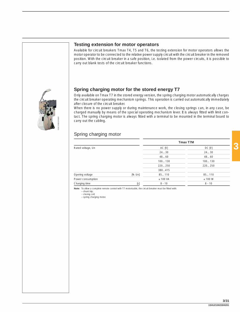
3
3/31
1SD
C21
0D23
F000
1
Testing extension for motor operatorsAvailable for circuit breakers Tmax T4, T5 and T6, the testing extension for motor operators allows the motor operator to be connected to the relative power supply circuit with the circuit breaker in the removed position. With the circuit breaker in a safe position, i.e. isolated from the power circuits, it is possible to carry out blank tests of the circuit breaker functions.
Spring charging motor for the stored energy T7Only available on Tmax T7 in the stored energy version, the spring charging motor automatically charges the circuit breaker operating mechanism springs. This operation is carried out automatically immediately after closure of the circuit breaker.When there is no power supply or during maintenance work, the closing springs can, in any case, be charged manually by means of the special operating mechanism lever. It is always fi tted with limit con-tact. The spring charging motor is always fi tted with a terminal to be mounted in the terminal board to carry out the cabling.
Spring charging motor
Tmax T7M
Rated voltage, Un AC [V] DC [V]
24…30 24…30
48…60 48…60
100…130 100…130
220…250 220…250
380...415
Opering voltage [% Un] 85…110 85…110
Power consumption ≤ 100 VA ≤ 100 W
Charging time [s] 8 - 10 8 - 10
Note: To allow a complete remote control with T7 motorizable, the circuit breaker must be fi tted with: – shunt trip; – closing coil; – spring charging motor.
1SXU210023D0201

3
3/32
Adapters – ADPFor the SOR, PS-SOR, UVR, AUX, MOE or MOE-E and AUE pre-wired electrical accessories used with Tmax T4, T5 and T6 in the plug-in or draw out versions, it is necessary to use the adapters to be coupled with the plug, which will then be connected to the socket on the cradle.According to the electrical accessories required, one or two adapters must be mounted on the left and/or right side of the moving part.There are four adapter types available:– 5-way adapters – 6-way adapters – 10-way adapters – 12-way adapters.The table below indicates the adapters which have to be used for the various possible combinations of electrical accessories:
Adapters ADP for T4, T5 and T6 wired accessories
5- way 6- way 10- way 12- way
Left side
SOR ■
UVR ■
SA for residual current release RC222 ■
SOR or UVR + SA for residual current release RC222 ■
MOE (MOE-E) ■
MOE (MOE-E) + SOR or UVR ■
MOE (MOE-E) + SOR or UVR + SA for residual current release RC222 ■
AUE ■
AUE + SOR or UVR ■
AUE + SOR or UVR + SA for residual current release RC222 ■
Right side
AUX 1Q + 1SY 1 open/closed changeover contact +1 trip unit tripped changeover contact ■
AUX 2Q 2 open/closed changeover contacts ■
AUX 3Q + 1SY 3 open/closed changeover contacts +1 trip unit tripped changeover contact ■
On the other hand, for Tmax T2 and T3 in the plug-in version it is necessary, to order the socket-plug connectors: with 12 poles for the AUX auxiliary contacts - 3 open/closed changeover + 1 release tripped changeover, with 6 poles for the AUX auxiliary contacts -1 open/closed changeover + 1 release tripped changeover and with 3 poles for the service releases (SOR or UVR).For T2 in the plug-in version with PR221 electronic trip unit and suitable auxiliary contact, it is necessary to order a 6 and a 3 pole socket-plug connector.
AccessoriesRemote control
1SXU210023D0201

3
3/33
Socket plug connectorsIn order to allow the racking-in and racking-out operations of the moving part of the plug-in circuit breaker, the wired and unwired electrical accessories of Tmax T2 and T3 and the unwired electrical accessories of Tmax T4, T5 and T6 must be fi tted with one or more socket plug connectors, as per the table below.
Socket plug connectors
3 poles 6 poles 12 poles
T2-T3-T4-T5-T6
SOR ■
UVR ■
AUX 1Q +1SY 1 open/closed changeover contact +1 trip unit tripped changeover contact ■
AUX 2Q 2 open/closed changeover contacts ■
AUX 3Q + 1SY 3 open/closed changeover contacts +1 trip unit tripped changeover contact ■
T2-T3
MOS overload(1) ■
AUE ■
AUX 2Q + 1SY for PR221 2 open/closed contacts +1 trip unit tripped changeover contact ■ ■
AUX 1S51 + 1Q + 1SY for PR2211 changeover contact + 1 SA electronic release trip contact +1 trip unit tripped changeover contact ■ ■
(1) Always provided with the overlaid solenoid operator
1SXU210023D0201

3
3/34
1SD
C21
0C77
F000
1
1SD
C21
0C78
F000
1
T4-T6
1SD
C21
0C79
F000
1
T4-T6
Rotary handle operating mechanism – RHD/RHE (UL FILE: E116596)Thanks to its ergonomic grip, the rotary handle facilitates the circuit breaker closing and opening opera-tions.It is always fi tted with a padlock-lock in the open position which prevents circuit breaker closing. The opening in the padlock-lock can take up to 3 padlocks - Ø 0.27” (7 mm) stem (not supplied), 0.24” (6 mm) only for Ts3 (not supplied). It is always (except for Ts3) fi tted with a compartment door lock and on request it can be supplied with a key lock in the open position. On request, the Ts3 can be supplied with a compartment door lock or key lock in the open position. Application of the rotary handle operating mechanism is an alternative to the motor operator and to the front interlocking plate (MIF) for T1, T2 and T3, or to the motor operator and to the front for lever operating mechanism for Ts3, T4, T5 and T6. The rotary handle operating mechanism is available in either the direct mount or variable depth version on the compartment door. The rotary handle operating mechanism in the emergency version, complete with a red on yellow background handle, suitable for controlling machine tools, is available in both the versions.The rotary handle operating mechanism is available on T7 with lever operating mechanism and, only for the direct mount version, is characterised by an articulated grip which allows the switchgear door to be opened in case of an emergency with the circuit breaker closed. The release settings and nameplate data remain accessible to the user.The variable depth rotary handle operating mechanisms can be ordered by building up the following three devices:– rotary handle on the compartment door– shaft (19.68”/500 mm)– base for circuit breaker or, alternatively, by using the code of the ready-confi gured version.
AccessoriesOperating mechanisms and locks
Type of RH_ operating mechanism
T1 T2, T3 Ts3 T4, T5 T6 T7(1)
F F P F P W F P W F W F WRHD Direct ■ ■ ■ ■ ■ ■ ■ ■ ■ ■ ■ ■ ■
RHD_EM Emergency direct ■ ■ ■ ■ ■ ■ ■ ■ ■ ■ ■ ■ ■
RHE Transmitted with adjustable distance ■ ■ ■ ■ ■ ■ ■ ■ ■ ■ ■ ■ ■
RHE_EM Emergency transmitted with adjustable distance ■ ■ ■ ■ ■ ■ ■ ■ ■ ■ ■ ■
RHE_B Base for circuit breaker ■ ■ ■ ■ ■ ■ ■ ■ ■ ■
RHE_S Shaft for variable depth handle ■ ■ ■ ■ ■ ■ ■ ■ ■ ■ ■ ■
RHE_H Handle for transmitted RH with variable depth ■ ■ ■ ■ ■ ■ ■ ■ ■ ■
RHE_H_EM Emergency handle for transmitted RH with variable depth ■ ■ ■ ■ ■ ■ ■ ■ ■ ■
(1) The rotary handle operating mechanism is only available for T7 with lever operating mechanism and it is as an alterative to the key lock mounted on the circuit breaker.
1SXU210023D0201

3
3/35
1SD
C21
0C80
F000
1
1SD
C21
0C81
F000
1
1SD
C21
0C82
F000
1
1SD
C21
0C83
F000
1
1SD
C21
0C84
F000
1
T1-T3
The IP54 protection for rotary handle (UL FILE: E116596)Allows IP54 degree of protection to be obtained. It is available for the transmitted rotary handle operating mechanism on the compartment door (RHE) for all the Tmax circuit breakers.
Front for lever operating mechanism – FLD (UL FILE: E116596)This can be installed on fi xed, plug-in or draw out Tmax Ts3, T4, T5 and T6 circuit breakers. In the case of draw out circuit breakers, installed in a switchboard, it allows the IP40 degree of protection to be maintained for the whole isolation run of the circuit breaker.It is always fi tted with a padlock in the open position Ø 0.24” (6 mm) stem up to three padlocks (not sup-plied) which prevents closing of the circuit breaker and of the compartment door, and with compartment door lock. On request, it can be fi tted with a key lock in the open position.It is available in the following versions:– for fi xed or plug-in circuit breaker– for draw out circuit breaker.The front for lever operating mechanism is always an alternative to the motor operator and to the rotary handle and to the display FDU.The same fl ange for the compartment door already supplied with the circuit breaker or the one supplied with the conversion kit for draw out (except for Ts3) version can be used.
Padlock for operating lever – PLLThis is applied to the T1 - T2 - T3 circuit breaker cover to prevent the lever closing or opening operation. It allows installation up to a maximum of three padlocks Ø 0.24” (7 mm) stem (not supplied). It is avail-able in the following versions:– plug-in locking device only of the closing operation– locking plate on the closing and opening operation according to the assembly position. The lock on
the opening operation does not prevent release of the mechanism following a fault or remote control command
– locking plate just for the closing operation.It is incompatible with the front accessories: solenoid operator, rotary handle operating mechanism and mechanic interlock.The padlock is also available for T7 and it is directly mounted on the circuit breaker cover.
T1-T3
1SXU210023D0201

3
3/36
1SD
C21
0C85
F000
11S
DC
210C
86F0
001
1SD
C21
0D24
F000
1Key lock on the circuit breaker for T1, T2, T3 and T7 – KLCThis allows the mechanical closing operation of the circuit breaker to be locked and is installed directly on the front in the slot in correspondence with the left pole. This cannot be installed when the front operating mechanism, rotary handle operating mechanism, motor operator, or RC221/RC222 residual current releases are present, or on the three-pole circuit breakers equipped with service releases (UVR, SOR). The key lock is the Ronis 622 type and is available in two versions:– standard type, with key only removable with the circuit breaker locked– special type, with key removable in both positions.On T7 the key lock in the open position is mounted directly on the circuit breaker cover both in the ver-sion with different keys and with the same keys. Presettings for Ronis and Profalux key locks are also available.
Key lock for Ts3, T4, T5, T6 and T7 – KLF-D and KLF-SThis allows mechanical operation of the circuit breaker to be locked. This lock can be used withthe direct or transmitted rotary handle operating mechanism mounted on the base for circuit breaker or with the front for lever operating mechanism. The lock of the circuit breaker in the open position ensures isolation of the circuit in accordance with the IEC 60947-2 Standard. For Ts3 different locks are supplied for the direct action motor operator, for stored energy motor operator, for rotary handle or front for lever operating mechanism. For T4, T5, T6 and T7 in the lever operating mechanism version key locks in the open position are available either with different keys (KLF-D) or with the same keys (KLF-S): in this case, up to four different key numbering codes are available (n. 2005-2006-2007-2008).
Key lock for rotary handle operating mechanism for T1, T2 and T3 – RHLThis allows the mechanical closing operation of the circuit breaker to be locked.The following versions are available:– lock with a different key for each circuit breaker– lock with the same key for groups of circuit breakers.The circuit breaker in the open position ensures isolation of the circuit in accordance to the IEC 60947-2 Standard. It is also available in the version which allows the lock both in the open and closed position. The lock in the closed position does not prevent release of the mechanism following a fault or remote control.
Lock in the racked-out position for cradle (Ts3, T4, T5 and T6)For Ts3, T4, T5 and T6 draw out circuit breakers, key or padlocks locks are available to be applied onto the rail of the cradle, to prevent racking-in of the plug-in part.Selection can be made among the following:– key lock with different keys (KLF-D FP)– key lock with the same keys for groups of circuit breakers (KLF-S FP)– Ronis type key lock (KLF-D Ronis FP)– padlock, which can take up to three padlocks with Ø 0.24” (6 mm) stem, not supplied (PLL FP).
AccessoriesOperating mechanisms and locks
1SXU210023D0201

3
3/37
1SD
C21
0C87
F000
1
1SD
C21
0D24
F000
11S
DC
210D
25F0
001
Lock in racked-in – isolated – racked-out position for cradle of T7This device allows the moving part of a draw out T7 circuit breaker to be locked in the racked-in, isolated-test or racked-out position in the relative cradle. Thanks to mounting an additional accessory, the lock can be limited just to the racked-out position.The cradle can be equipped with 1 or 2 of these key locks.
Mechanical lock of compartment doorA mechanical lock of compartment door available on Ts3 and T7 for both the lever operating mechanism and for the motorizable version. It does not allow the compartment door to be opened with the circuit breaker closed (and circuit breaker racked-in for circuit breakers in the draw out version) and locks the circuit breaker closing with the compartment door open.For Ts3 circuit breakers, it consists of two elements: one applied to the rotary handle operating mechanism or to the front for the lever operating mechanism, the other consisting of a metal striker to be applied onto the compartment door.For T7 two versions are available: a door lock made by means of cables and a second type fi xed directly on the side of the circuit breaker or of the relative cradle. The cable door lock must also be fi tted with the interlock cable kit and the interlocking plate corresponding to the combined circuit breaker.
Sealable thermal adjustment lockThis is applied to the circuit breaker cover near the thermal element regulator of the TMD thermomagnetic trip unit for T1, T2, T3 and Ts3 and prevents it being tampered with.
Overview of the available locks
T1 T2 T3 Ts3 T4 T5 T6 T7
FDL Front for lever operating mechanism ■ ■ ■ ■
PLL_ Padlock for operating lever ■ ■ ■ ■
KLC_ Key lock on the circuit breaker ■ ■ ■ ■
RHL Keylock for rotary handle operating mechanism ■ ■ ■
KLF-D and KLF-S Key lock for front for lever and rotary handle ■ ■ ■ ■
MOL-D and MOL-S_ Key lock in open position for MOE and MOE_E ■ ■ ■
MOL-M_ Key lock against manual operation for MOE and MOE_E ■ ■ ■
KLF-FP and PLL FP_ Locks in open position for cradle ■ ■ ■ ■
Mechanical lock on compartment door ■ ■
Sealable lock of thermal adjustment ■ ■ ■ ■
1SXU210023D0201

3
3/38
1SD
C21
0C88
F000
11S
DC
210C
89F0
001
1SD
C21
0D26
F000
1
Mechanical interlock (UL FILE: E116596)T1-T2-T3The mechanical MIF interlock can be applied on the front of two T1, T2 or T3 circuit breakers mounted side by side, in either the three-pole or four-pole fi xed version and prevents simultaneous closing of the two circuit breakers. Fixing is carried out directly on the back plate of the switchboard. The front interlocking plate allows installation of a padlock in order to fi x the position (possibility of locking in the O-O position as well). It is also possible to interlock three circuit breakers side by side, using the proper plate, thereby making the following interlock combinations: IOO-OIOOOI-OOO. It is incompatible with the front acces-sories (solenoid operator, rotary handle operating mechanism) and with the residual current releases.
T3For T3, in the three-pole or four-pole fi xed or plug-in version, the MIR mechanical interlock is available. This rear interlock, available in the horizontal (MIR-H) and vertical (MIR-V) version, is compatible with all the front accessories and with the residual current release (only MIR-H).The following interlocking combinations can be made: IO-OI-OO.
Ts3For Ts3 circuit breakers the (rear) mechanical interlock allows installation of two circuit breakers in a single support and, by means of a walking beam mechanism, makes them mechanically interdependent. It prevents operation in parallel of two power supply sources (eg. normal-emergency). It consists of a kit with levers and assembly accessories and a metallic support. The mechanical interlock is available in the version for side-by-side circuit breakers and for superimposed circuit breakers. Only circuit breakers of the same size and in the same version can be interlocked.
T4-T5-T6The mechanical interlock for T4, T5 and T6 allows installation of two circuit breakers on a single support and, by means of special lever mechanisms, makes them mechanically interdependent.For Tmax T4 and T5 this is a rear interlock consisting of a vertical or horizontal frame group (MIR-HR or MIR-VR) and of a pair of metal plates for fi xing the circuit breakers (MIR-P). The frame group is made up of metal frame and of the lever mechanism interlock. The metal plates are of different type according to the sizes of the circuit breakers to be interlocked. For Tmax T6 this is a rear interlock consisting of a vertical or horizontal support.
Interlock
Type
A T4 (F-P-W) + T4 (F-P-W)
B T4 (F-P-W) + T5 400 (F-P-W) o T5 630 (F)
C T4 (F-P-W) + T5 630 (P-W)
D T5 400 (F-P-W) o T5 630 (F) + T5 400 (F-P-W) o T5 630 (F)
E T5 400 (F-P-W) o T5 630 (F) + T5 630 (P-W)
F T5 630 (P-W) + T5 630 (P-W)
There are no limitations on the versions to be interlocked, therefore, for example, a fi xed circuit breaker can be interlocked with a draw out version switch-disconnector.Since this is a rear interlock, all the front accessories which are compatible with the circuit breakers can be used.In the vertical interlock the bottom terminals of the upper circuit breaker and the top terminals of the lower circuit breaker must be of rear type.To be able to receive the circuit breakers mounted directly on the interlocking plate, code “1SDA050093R1” must be specifi ed as the accessory of the second circuit breaker (or cradle) you want to interlock.
T1-T2-T3
T3-T4-T5-T6
AccessoriesOperating mechanisms and locks
1SXU210023D0201

3
3/39
1SD
C21
0D28
F000
1
1SD
C21
0D27
F000
1
T7This mechanism makes the mechanical interlock between two T7 circuit breakers by means of fl exible cables, which are connected on a plate mounted on the side of the circuit breaker preventing simultane-ous closing of the two circuit breakers. The plates to be mounted on the circuit breaker differ according to whether the circuit breaker is in the fi xed or draw out version.The interlock is available both for the manual operating mechanism version and for the motor operator one.
Transparent pushbutton protection – TCPA transparent protection for the circuit breaker opening and closing pushbuttons is available in two differ-ent versions on T7 with stored energy operating mechanism: one which protects both the pushbuttons and the other which alternatively protects either the opening or the closing pushbutton.There is the possibility of putting a padlock, which adds the lock function to the protection. In the closed position this lock does not prevent release of the mechanism following a fault or a remote command.
IP54 door protectionAvailable with T7 motorizable, it is made by means of a transparent plastic cover which completely pro-tects the front of the circuit breaker and allows IP54 degree of protection to be reached. Mounted on hinges, it is provided with a key lock.
1SXU210023D0201

3
3/40
All the Tmax series of circuit breakers, both automatic circuit breakers and switch-disconnectors, are preset for assembly with residual current releases.In particular, the Tmax T1, T2 and T3 circuit breakers can be combined with the new version of the SACE RC221 or RC222 series of residual current releases. Tmax Ts3 can be combined with SACE RC211 or RC212 residual current releases and four-pole T4 and T5 with RC222 or RC223 to be installed below the circuit breaker.The T6 and T7 circuit breakers can be combined with the RCQ residual current switchgear release. Apart from the protection against overloads and short-circuits typical of automatic circuit breakers, the residual current circuit breakers derived from them also guarantee protection of people and protection against ground fault currents, thereby ensuring protection against direct contacts, indirect contacts and fi re hazards. The residual current releases can also be mounted on the Tmax T1D, T3D, T4D and T5D switch-disconnectors. In that case, the derived apparatus is a “pure” residual current circuit breaker, i.e. one which only guarantees residual current protection and not the protections typical of circuit breakers. “Pure” residual current circuit breakers are only sensitive to the ground fault current and are generally applied as main switch-disconnectors in small distribution switchboards towards end users.The use of “pure” and “impure” residual current circuit breakers allows continual monitoring of the state of plant insulation, ensuring effi cient protection against fi re and explosion hazards and, when the devices have IΔn ≤ 30 mA, ensure protection of people against indirect and direct ground contacts to fulfi l the compulsory measures foreseen by the accident prevention regulations and prescriptions.The residual current releases are constructed in compliance with the following Standards:– IEC 60947-2 appendix B– IEC 61000: for protection against unwarranted release.
They are constructed using electronic technology and act directly on the circuit breaker by means of a trip coil, supplied with the residual current release, to be housed in the special slot made in the left-hand pole area.They do not require an auxiliary power supply as they are supplied directly by the network and their operation is guaranteed even with only a single phase plus neutral or only two phases supplied with voltage and in the presence of unidirectional pulsating currents with direct components. All the possible connection combinations are allowed, except for guaranteeing, in the four-pole version, connection of the neutral to the fi rst pole on the left.
The RC221 and RC222 residual current releases can either be supplied from above or from below.The operating conditions of the apparatus can be continually controlled by the electronic circuit test pushbutton and the magnetic indicator of residual current trip.A disconnection device of the power supply during the insulation test is available.The four-pole circuit breaker complete with residual current release can be fi tted with the electrical ac-cessories normally available for the circuit breaker. The shunt opening and undervoltage releases are housed in the special slot made in the neutral pole for the four-pole circuit breakers, whereas they are incompatible with the three-pole circuit breakers.
The residual current releases are supplied complete with:– a trip coil to be housed in the area of the third pole, complete with an auxiliary contact signalling
residual current release trip– dedicated fl ange.
A changeover contact for signalling residual current protection trip is always supplied for Tmax circuit breakers, combined with the RC221 and RC222 residual current releases. Two changeover contacts for signalling pre-alarm and alarm are also available with the RC222 release.The opening solenoid for the RC221, RC222 and RC223 residual current releases is available as a spare part.A circuit breaker cannot have the residual current release and the rotary handle or the motor operator mounted at the same time (except for MOS in the side-by-side version for T1 and T2).
AccessoriesResidual current releases - IEC only
1SXU210023D0201

3
3/41
1SD
C21
0C90
F000
1 U
L1S
DC
210C
91F0
001
T1-T2-T3
1SD
C21
0681
F000
3
beside
RC221 and RC222 residual current releases for T1, T2 and T3The RC221 and RC222 residual current releases for T1, T2 and T3 circuit breakers are available both with three-pole and four-pole circuit breakers, in the fi xed version. The confi guration foresees insertion of the circuit breaker on the structure of the corresponding residual current release, making access to the adjustments on the left-hand side of the circuit breaker available, whilst the toroid is in the underneath position.A distinguishing characteristic is provided by the type of cable connection which is made directly on the circuit breaker, once the residual current release has been mounted, thereby ensuring simplifi cation and rationalisation of the installation procedure.With Tmax T2 and T3, only front terminals for copper cables (FC Cu) at the bottom are mounted on the residual current releases.For this reason, when the residual current release is ordered, the FC Cu terminal semi-kit is always sup-plied.On the other hand, for four-pole Tmax T1, it is also possible to mount the rear horizontal fl at terminal kit below (HR for RC221/RC222).Furthermore for four-pole T1 a version of the RC222 residual current release is available in 7.87” (200 mm) modules. This release keeps the same technical characteristics as the normal RC222 for T1, T2 and T3 but thanks to its reduced height, allows installation in 7.87” (200 mm) modules. Its special shape also allows a reduction in the overall dimensions when two or more units are placed side by side.The bracket for fi xing onto DIN 50022 rail is available on request.A circuit breaker cannot have the residual current release and the overlaid solenoid operator or the rotary handle operating mechanism mounted at the same time.
SACE RC211 and RC212 electronic residual current releases for Ts3The SACE RC211 or RC212 residual current releases can be installed on the Tmax Ts3 circuit breaker, in the fi xed, four-pole version and can be supplied in two versions as follows:– for assembly beside the circuit breaker– for assembly under the circuit breaker.They are constructed using analogue technology and act directly on the circuit breaker by means of an opening solenoid, supplied with the release, to be housed in the special slot made in the area of the third pole.They do not require an auxiliary power supply since they are supplied directly from the network and their operation is guaranteed even with only a single phase supplied with voltage and in the presence of one-direction pulsating currents with continuous components. The operating conditions of the apparatus can be controlled constantly by means of the test pushbutton of the electronic circuit and the residual current trip magnetic indicator.The circuit breaker complete with residual current release can be fi tted with the electrical accessories normally available for the circuit breaker. The opening and undervoltage releases are housed in the special slot made in the fourth pole.
Residual current release beside the four-pole version circuit breaker This is supplied complete with:– power cables for connection to the lower terminals of the circuit breaker (respect correspondence
with the neutral and phases)– an opening solenoid to be housed in the area of the third pole, complete with plug-socket connector
for connection to the residual current release– 2 brackets for fi xing on DIN rail (one for the circuit breaker and one for the residual current release)– plug connector to make the connection of the remote opening pushbutton (to be provided by the
customer).For the Tmax Ts3 circuit breaker, the residual current release is fi tted with front terminals and is also supplied with a front fl ange H = 1.77” (45 mm) for the circuit breaker. On request, the front terminals for cables can be mounted, using the standard circuit breaker kit.
1SXU210023D0201

3
3/42
1SD
C21
0C92
F000
1 U
L1S
DC
210C
93F0
001
T4-T5
RC222 residual current release for T4 and T5The RC222 release for T4 and T5 is available in the four-pole version and is mounted below the circuit breaker.The release is supplied with standard front terminals, but it can also be combined with all the terminals available for the corresponding circuit breaker.The RC222 residual current release, in the fi xed version, can easily be converted into plug-in and into draw out by adding the special conversion kit and applying a derating of the performances as indicated in the table on the next page.A circuit breaker cannot have the residual current release and the motor operator mounted at the same time.
RC223 (B type) residual current release for T3 and T4 250 AThe RC223 (B type) residual current release can only be combined with the Tmax T3 and T4 250 A four-pole circuit breakers in the fi xed, plug-in and draw out version (plug-in and draw out version only for T4). The range of operation of the primary line-to-line voltage of this residual current release varies between 110 V and 500 V, with operation starting from 55 V phase-neutral. It is characterised by the same types of reference as the RC222 (S and AE type) release, but can also boast conformity with type B operation, which guarantees sensitivity to residual fault currents with alternating, alternating pulsating and direct current components.The reference Standards are: IEC 60947-1, IEC 60947-2 Appendix B, and IEC 60755.Apart from the signals and settings typical of the RC222 residual current release, the RC223 also allows selection of the maximum threshold of sensitivity to the residual fault frequency (3 steps: 400 - 700 - 1000 Hz). It is therefore possible to adapt the residual current device to the different requirements of the industrial plant according to the prospective fault frequencies generated on the load side of the release. Typical installations which may require frequency thresholds different from the standard ones (50 - 60 Hz) are the welding plants for the automobile industry (1000 Hz), the textile industry (700 Hz), airports and three phase drives (400 Hz).A circuit breaker cannot have the residual current release and the motor operator mounted at the same time.The residual current RC223 for T3 has front terminals as default. For connection to the T3+RC223 unit, use the terminal kits available for size T3 on the top terminals and terminal kits for T4 on the bottom terminals.
AccessoriesResidual current releases - IEC only
1SXU210023D0201

3
3/43
RC222-RC223 T4-T5 Performances
Maximum withstand current
Fixed Plug-in/Draw out
T3 250 A(1) −
T4 250 250 A 250 A
T5 400(2) 400 A 400 A
T5 600(2) 500 A −(1) 225 A with RC223(2) Available only with RC222
RC211 RC212 RC221 RC222 RC223
Circuit breakers sizeTs3
(4p only)Ts3
(4p only)T1-T2-T3 T1-T2-T3
T4 and T5 (4p only)
T3 and T4(4p only)
Type beside/below beside/below “L” shaped “L” shaped placed below placed below
Technology microprocessor-based microprocessor-based microprocessor-based microprocessor-based microprocessor-based microprocessor-based
Action with solenoid with solenoid with trip coil with trip coil with trip coil with trip coil
Primary service voltage(1) [V] 220…500 50…500 85…500 85…500 85…500 110…500
Operating frequency [Hz] 45…66 45…66 45…66 45…66 45…66 45…66
Self-supply ■ ■ ■ ■ ■ ■
Test operation range(1) [V] 220…500 50…500 85…500 85…500 85…500 110…500
Rated service current [A] up to 250 A up to 250 A up to 250 A up to 250 A up to 500 A up to 250 A (225 A for T3)
Rated residual current trip [A] 0.03-0.1-0.3 0.03-0.1-0.3-0.5-3 0.03-0.1-0.3-0.5-1-3
0.03-0.05-0.1-0.3-0.5-1-3-5-10
0.03-0.05-0.1-0.3-0.5-1-3-5-10
0.03-0.05-0.1-0.3-0.5-1
Time limit for non-trip [s] instantaneous 0.1-0.25-0.5-1-1.5 instantaneous instantaneous 0.1-0.2-0.3-0.5-1-2-3
instantaneous 0.1-0.2-0.3-0.5-1-2-3
instantaneous 0.1-0.2-0.3-0.5-1-2-3
Tolerance over trip times ± 20% ± 20% ± 20% ± 20%
Power consumption(2) < 8 W at 400 V AC < 10 W at 400 V AC < 10 W at 400 V AC < 10 W at 400 V AC
Local trip signalling ■ ■ ■ ■ ■ ■
Trip coil with changeover contact for trip signalling
■ ■ ■ ■ ■ ■
Input for remote opening ■ ■ ■ ■
NO contact for pre-alarm signalling ■ ■ ■
NO contact for alarm signalling ■ ■ ■
Indication of pre-alarm from 25% IΔn (tollerance ±3%)
■ ■ ■
Indication of alarm timing at 75% IΔn (tollerance ±3%)
■ ■ ■
“A” type for pulsanting alternating current, AC for alternating current
■ ■ ■ ■ ■ ■
“AE” type for remote release device ■ ■ ■
Type B for pulsed current and direct current ■
Selective “S” type ■ ■ ■
Switch for insulation test ■ ■ ■ ■
Power supply from above and below ■ ■ ■ ■
Assembly with three-pole circuit breakers ■ ■
Assembly with four-pole circuit breakers ■ ■ ■ ■ ■ ■
Kit for conversion of circuit breaker with residual current release from fi xed to plug-in
■ ■
(1) Operation up to 50 V Phase-Neutral (55 V for RC223)(2) The values of power consumption can be inferior at lower supply voltage
1SXU210023D0201

3
3/44
1SD
C21
0C94
F000
1
Residual current relay SACE RCQ
Power supply voltage AC [V] 80 ... 500
DC [V] 48 ... 125
Operating frequency [Hz] 45 ÷ 66 Hz
Power consumption on in rush 100 [VA] / 100 [W]
Power consumption in service 6 [VA] / 6 [W]
Trip threshold adjustment IΔn
1st range of adjustments [A] 0.03-0.05-0.1-0.3-0.5
2nd range of adjustments [A] 1-3-5-10-30
Trip time adjustment [s] instantaneous 0.1-0.2-0.3-0.5-0.7-1-2-3-5
Pre-alarm threshold adjustment [%] x IΔn 25 ... 75% x IΔn
Range of use of closed transformers
Toroidal transformer Ø 2.36”/60 mm [A] 0.03 ... 30
Toroidal transformer Ø 4.33”/110 mm [A] 0.03 ... 30
Toroidal transformer Ø 7.28”/185 mm [A] 0.1 ... 30
Range of use of transformers which can be opened
Toroidal transformer Ø 4.33”/110 mm [A] 0.3 ... 30
Toroidal transformer Ø 7.08”/180 mm [A] 0.3 ... 30
Toroidal transformer Ø 9.05”/230 mm [A] 1 ... 30
Signalling for alarm pre-threshold Yellow fl ashing LED 1 N.O., change-over contact
6 A - 250 V AC 50/60 Hz
Residual current relay trip signalling Yellow magnetic fl ag change-over contacts (N.O. N.C.; N.O.)
6 A - 250 V AC 50/60 Hz
Remote opening control N.O. contact - Trip time 15 ms
Connection to the toroidal transformer By means of 4 twisted conductors. Maximum length: 5 m
Dimensions W x H x D [In/mm] 3.77” x 3.77” x 5.17” / 96 x 96 x 131.5 mm
Drilling for assembly on door [In/mm] 3.62” x 3.62” / 92 x 92 mm
Degree of protection on the front IP41
Degree of protection on the rear IP30
SACE RCQ switchboard residual current relay (IEC only)The Tmax circuit breakers can also be combined with the SACE RCQ switchboard relay with separate toroid (to be installed externally on the line conductors) and these fulfi l requirements with thresholds up to 30 A trips and times up to 5 s or when the installation conditions are particularly restrictive, such as with circuit breakers already installed, or limited space in the circuit breaker compartment.Thanks to the wide range of settings, the SACE RCQ switchboard relay is suitable for applications where a system of residual current protection coordinated with the various distribution levels, from the main switchboard to the end user, is required. It is particularly recommended when low sensitivity residual cur-rent protection is required, such as in partial (current) or total (chronometric) selective chains, and for high sensitivity applications (physiological sensitivity) to provide protection of people against direct contacts.On a drop in the auxiliary power supply voltage, the opening command can intervene after a minimum time of 100 ms and after the time set plus 100 ms.The SACE RCQ relay is a type A residual current relay and detects residual currents both of the alternat-ing and pulsating type with continuous components.The SACE RCQ relay is of the type with indirect action and acts on the circuit breaker release mechanism by means of the shunt trip (or of the undervoltage release) of the circuit breaker itself (to be ordered by the user). It is housed in the special slot made on the left-hand pole of the circuit breaker.
AccessoriesResidual current releases - IEC only
1SXU210023D0201

3
3/45
1SD
C21
0C95
F000
11S
DC
210D
39F0
001
1SD
C21
0D31
F000
1
Front display unit – FDUThe front display is a display unit of the setting currents, alarms and parameters of the PR222DS/P and PR222DS/PD-A electronic trip units of T4, T5 and T6. The display unit can operate correctly with self-supply with I ≥ 0.35 x In on at least one phase.If the display is used in combination with the PR222DS/PD-A trip unit, and therefore with an auxiliary power supply, it is also possible to detect the protection which has caused the release trip and the fault current.It is not compatible with the front accessories: rotary handle operating mechanism, motor operator and front for lever operating mechanism.
HMI030 interface on the front of switchgearThis accessory, which can be used with all the protection trip units fi tted with dialogue, is designed for installation on the front of the switchgear. It consists of a graphic display where all the trip unit measure-ments and alarms/events are displayed. The user can navigate in a simple and intuitive way among the measurements by using the navigation pushbuttons. The device can replace the traditional multimeters without the need for current/voltage transformers. The HMI030 is connected directly to the protection trip unit by means of a serial line and requires a 24 V DC power supply.
Optional modulesThe PR332/P trip unit for T7 can be enriched with additional internal modules, thereby increasing the capacity of the trip units and making these units highly versatile.
PR330/V voltage measuring moduleThis optional internal module can be added to PR332/P. It measures and processes the phase and neutral voltages, transferring this data to the protection trip unit so that a series of protection and measurement functions can be implemented. It can be connected to the PR332/P at any time and the latter recognises it automatically without having to be confi gured.PR330/V module, when ordered mounted on the circuit breaker, does not require any external connec-tion or voltage transformers since it is connected internally to the upper terminals of Tmax T7 (selector in “INT” position) though the internal voltage sockets.At the ordering stage, the code of the internal voltage socket can be specifi ed in addition to the code of the T7 circuit breaker so as to guarantee the possibility to install even afterwards the PR332/P trip unit equipped with the PR330/V module connected internally to the upper terminals. If necessary, the connection of the voltage sockets can be moved externally with connection to the terminal board using voltage transformers connected to the top or bottom terminals.On the PR330/V module there is a selector which defi nes the method of wiring implemented to detect the voltage measurements (INT = connection of the internal module towards the top terminals – EXT = connection to the terminal box). The “Insulating Test” position guarantees carrying out the dielectric test. A “Power Line” LED indicates presence of the line voltage.
PR330/D-M communication module (Modbus RTU)The PR330/D-M communication module is the solution for connecting Tmax to a Modbus network for remote supervision and control of the circuit breaker.It is suitable for the PR332/P trip unit for T7. As for the PR330/V, this module can be added to the protec-tion trip unit and its presence is recognised automatically. The electronic trip unit is supplied with three LEDs on the front:– “Power” power supply LED, which indicates the presence of auxiliary power supply to the
PR333/ D-M module– “Tx” data transmission LED – “Rx” data reception LED.
AccessoriesAccessories for electronic trip units
1SXU210023D0201
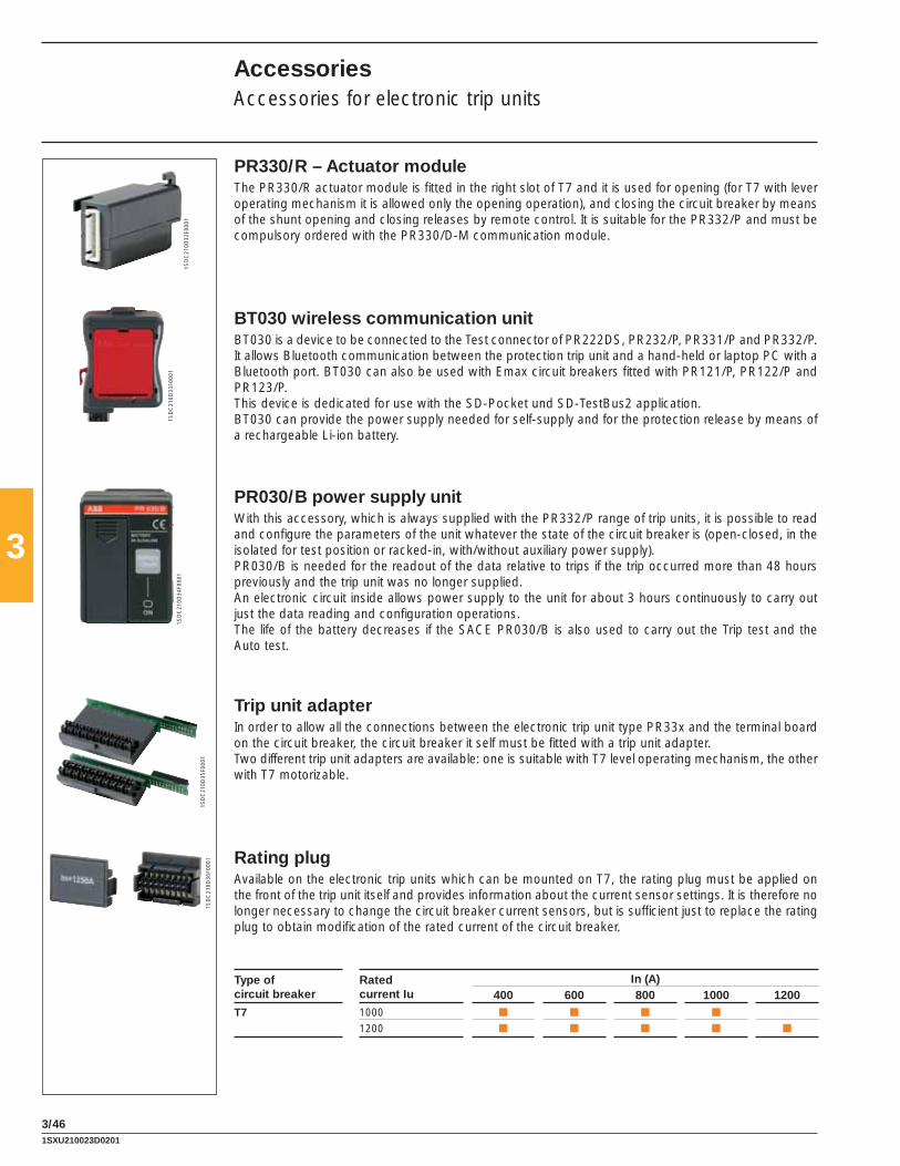
3
3/46
1SD
C21
0D32
F000
1
1SD
C21
0D33
F000
11S
DC
210D
34F0
001
1SD
C21
0D35
F000
11S
DC
210D
36F0
001
PR330/R – Actuator moduleThe PR330/R actuator module is fi tted in the right slot of T7 and it is used for opening (for T7 with lever operating mechanism it is allowed only the opening operation), and closing the circuit breaker by means of the shunt opening and closing releases by remote control. It is suitable for the PR332/P and must be compulsory ordered with the PR330/D-M communication module.
BT030 wireless communication unitBT030 is a device to be connected to the Test connector of PR222DS, PR232/P, PR331/P and PR332/P. It allows Bluetooth communication between the protection trip unit and a hand-held or laptop PC with a Bluetooth port. BT030 can also be used with Emax circuit breakers fi tted with PR121/P, PR122/P and PR123/P.This device is dedicated for use with the SD-Pocket und SD-TestBus2 application.BT030 can provide the power supply needed for self-supply and for the protection release by means of a rechargeable Li-ion battery.
PR030/B power supply unitWith this accessory, which is always supplied with the PR332/P range of trip units, it is possible to read and confi gure the parameters of the unit whatever the state of the circuit breaker is (open-closed, in the isolated for test position or racked-in, with/without auxiliary power supply).PR030/B is needed for the readout of the data relative to trips if the trip occurred more than 48 hours previously and the trip unit was no longer supplied.An electronic circuit inside allows power supply to the unit for about 3 hours continuously to carry out just the data reading and confi guration operations.The life of the battery decreases if the SACE PR030/B is also used to carry out the Trip test and the Auto test.
Trip unit adapterIn order to allow all the connections between the electronic trip unit type PR33x and the terminal board on the circuit breaker, the circuit breaker it self must be fi tted with a trip unit adapter.Two different trip unit adapters are available: one is suitable with T7 level operating mechanism, the other with T7 motorizable.
Rating plugAvailable on the electronic trip units which can be mounted on T7, the rating plug must be applied on the front of the trip unit itself and provides information about the current sensor settings. It is therefore no longer necessary to change the circuit breaker current sensors, but is suffi cient just to replace the rating plug to obtain modifi cation of the rated current of the circuit breaker.
Type of circuit breaker
Rated current Iu
In (A)400 600 800 1000 1200
T7 1000 ■ ■ ■ ■
1200 ■ ■ ■ ■ ■
AccessoriesAccessories for electronic trip units
1SXU210023D0201
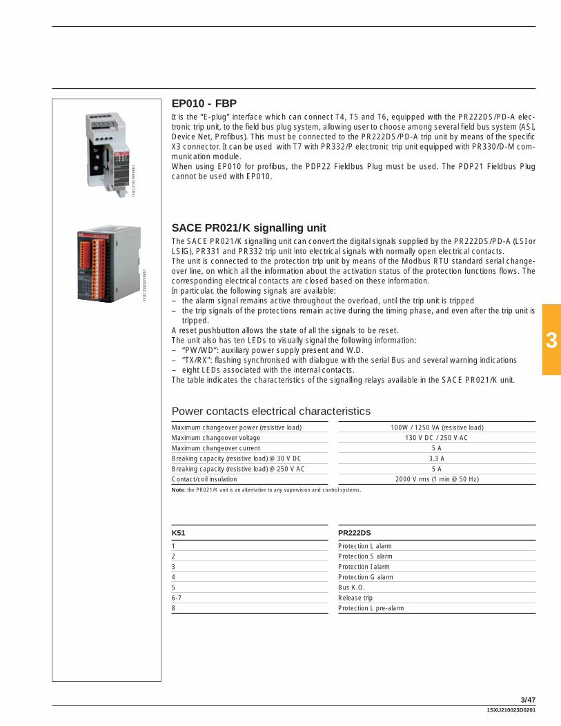
3
3/47
1SD
C21
0C99
F000
1
1SD
C21
0D37
F000
1
EP010 - FBPIt is the “E-plug” interface which can connect T4, T5 and T6, equipped with the PR222DS/PD-A elec-tronic trip unit, to the fi eld bus plug system, allowing user to choose among several fi eld bus system (ASI, Device Net, Profi bus). This must be connected to the PR222DS/PD-A trip unit by means of the specifi c X3 connector. It can be used with T7 with PR332/P electronic trip unit equipped with PR330/D-M com-munication module.When using EP010 for profi bus, the PDP22 Fieldbus Plug must be used. The PDP21 Fieldbus Plug cannot be used with EP010.
SACE PR021/K signalling unitThe SACE PR021/K signalling unit can convert the digital signals supplied by the PR222DS/PD-A (LSI or LSIG), PR331 and PR332 trip unit into electrical signals with normally open electrical contacts.The unit is connected to the protection trip unit by means of the Modbus RTU standard serial change-over line, on which all the information about the activation status of the protection functions fl ows. The corresponding electrical contacts are closed based on these information.In particular, the following signals are available:– the alarm signal remains active throughout the overload, until the trip unit is tripped– the trip signals of the protections remain active during the timing phase, and even after the trip unit is
tripped.A reset pushbutton allows the state of all the signals to be reset.The unit also has ten LEDs to visually signal the following information:– “PW/WD”: auxiliary power supply present and W.D.– “TX/RX”: fl ashing synchronised with dialogue with the serial Bus and several warning indications – eight LEDs associated with the internal contacts.The table indicates the characteristics of the signalling relays available in the SACE PR021/K unit.
Power contacts electrical characteristics Maximum changeover power (resistive load) 100W / 1250 VA (resistive load)
Maximum changeover voltage 130 V DC / 250 V AC
Maximum changeover current 5 A
Breaking capacity (resistive load) @ 30 V DC 3.3 A
Breaking capacity (resistive load) @ 250 V AC 5 A
Contact/coil insulation 2000 V rms (1 min @ 50 Hz)
Note: the PR021/K unit is an alternative to any supervision and control systems.
K51 PR222DS
1 Protection L alarm
2 Protection S alarm
3 Protection I alarm
4 Protection G alarm
5 Bus K.O.
6-7 Release trip
8 Protection L pre-alarm
1SXU210023D0201

3
3/48
AccessoriesAccessories for electronic trip units
Current sensor for external neutralThis is applied to the external neutral conductor and allows protection G against earth faults to be carried out with external neutral three-pole circuit breakers. The current sensor must be connected to the trip unit by means of the specifi c connectors X4 for T4, T5 and T6 or with a direct connection in the terminal board for T7. The combination is not possible with electronic trip unit PR221, PR231 and PR232.
T4 [A] T5 [A] T6 [A] T7 [A]
100 300 600 400
150 400 800 600
250 600 800
1000
1200
ConnectorsConnectors X3 and X4 allow connection of the electronic trip units with external plant units or components. In fact, they are used to make the L alarm signal available outside, connection of the external neutral, connection to the PR021/K signalling unit, to the PR212/CI contactor control unit or to the temperature sensor of the PTC motor and allows two-way communication from the circuit breaker fi tted with dialogue towards the outside and vice versa.Both the connectors are available both for fi xed version circuit breakers and for plug-in or draw out ver-sion circuit breakers.
Connector Function Trip unit
X3 PR021/K PR222DS/PD-A
L alarm signal PR222DS/P, PR222DS/PD-A
Auxiliary supply PR222DS/PD-A
EP 010 PR222DS/PD-A
X4 External neutral PR222DS/P, PR222DS/PD-A
1SXU210023D0201

3
3/49
Accessories for trip units
Circuit breakers T2-T4-T5-T6 T4-T5-T6 T7
Trip units PR221 PR222DS/P PR222DS/PD-A PR231/P PR232/P PR331/P PR332/P
Accessories
TT1 - Test unit ■ ■ ■ ■ ■
PR010/T - Test unit ■ ■ ■ ■ ■
PR021/K(1) - Signalling unit ■ ■ ■
FDU(2) - Front display unit ■ ■
HMI030(1) - Interface on the front of switchgear ■ ■ ■
X3 - Connectors ■ ■(3)
X4 - Connectors ■ ■
X13 - Connectors SHORT/LONG ■ ■ ■ ■
BT030 - Wireless communication unit ■ ■ ■ ■ ■
MOE-E (AUX-E included)(2) - Motor operator ■
AUX-E - Auxiliary contacts ■
EP010(1) - Field Bus plug ■ ■
CT - Current transformers ■ ■
Extracode for interchangeability ■
Rating plugs ■ ■ ■ ■
PR030/B - Power supply unit ■ ■ ■
PR330/D-M - Communication module ■
PR330/V - Voltage measuring module ■
PR330/R - Actuator module ■
CT Sensor - Current sensors ■ ■
(1) Accessories not compatible(2) Accessories not compatible(3) Compulsory
1SXU210023D0201
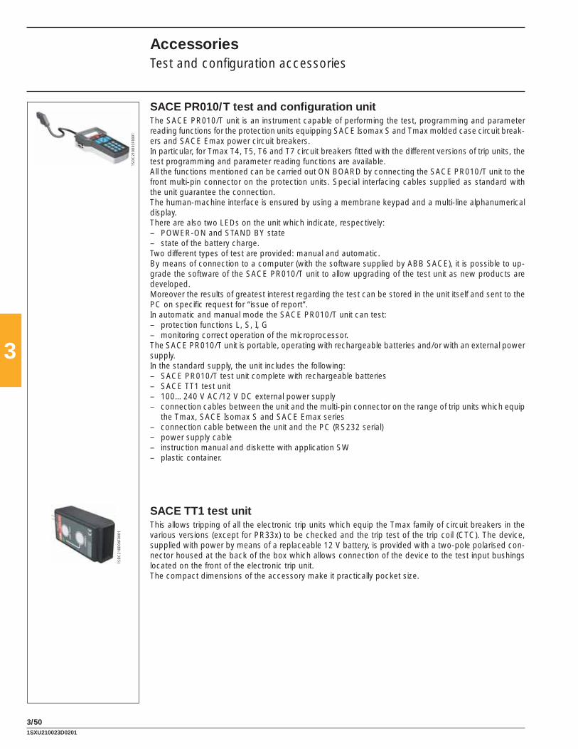
3
3/50
1SD
C21
0D03
F000
1
1SD
C21
0D04
F000
1
SACE PR010/T test and confi guration unitThe SACE PR010/T unit is an instrument capable of performing the test, programming and parameter reading functions for the protection units equipping SACE Isomax S and Tmax molded case circuit break-ers and SACE Emax power circuit breakers.In particular, for Tmax T4, T5, T6 and T7 circuit breakers fi tted with the different versions of trip units, the test programming and parameter reading functions are available.All the functions mentioned can be carried out ON BOARD by connecting the SACE PR010/T unit to the front multi-pin connector on the protection units. Special interfacing cables supplied as standard with the unit guarantee the connection.The human-machine interface is ensured by using a membrane keypad and a multi-line alphanumerical display.There are also two LEDs on the unit which indicate, respectively:– POWER-ON and STAND BY state– state of the battery charge.Two different types of test are provided: manual and automatic.By means of connection to a computer (with the software supplied by ABB SACE), it is possible to up-grade the software of the SACE PR010/T unit to allow upgrading of the test unit as new products are developed.Moreover the results of greatest interest regarding the test can be stored in the unit itself and sent to the PC on specifi c request for “issue of report”.In automatic and manual mode the SACE PR010/T unit can test:– protection functions L, S, I, G– monitoring correct operation of the microprocessor.The SACE PR010/T unit is portable, operating with rechargeable batteries and/or with an external power supply.In the standard supply, the unit includes the following:– SACE PR010/T test unit complete with rechargeable batteries– SACE TT1 test unit– 100…240 V AC/12 V DC external power supply– connection cables between the unit and the multi-pin connector on the range of trip units which equip
the Tmax, SACE Isomax S and SACE Emax series– connection cable between the unit and the PC (RS232 serial)– power supply cable– instruction manual and diskette with application SW – plastic container.
SACE TT1 test unitThis allows tripping of all the electronic trip units which equip the Tmax family of circuit breakers in the various versions (except for PR33x) to be checked and the trip test of the trip coil (CTC). The device, supplied with power by means of a replaceable 12 V battery, is provided with a two-pole polarised con-nector housed at the back of the box which allows connection of the device to the test input bushings located on the front of the electronic trip unit. The compact dimensions of the accessory make it practically pocket size.
AccessoriesTest and confi guration accessories
1SXU210023D0201
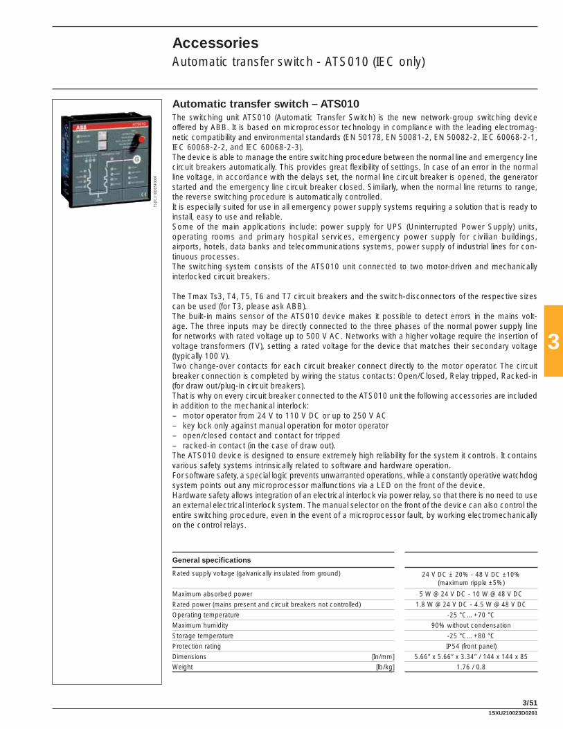
3
3/51
1SD
C21
0D05
F000
1
AccessoriesAutomatic transfer switch - ATS010 (IEC only)
Automatic transfer switch – ATS010The switching unit ATS010 (Automatic Transfer Switch) is the new network-group switching device offered by ABB. It is based on microprocessor technology in compliance with the leading electromag-netic compatibility and environmental standards (EN 50178, EN 50081-2, EN 50082-2, IEC 60068-2-1, IEC 60068-2-2, and IEC 60068-2-3). The device is able to manage the entire switching procedure between the normal line and emergency line circuit breakers automatically. This provides great fl exibility of settings. In case of an error in the normal line voltage, in accordance with the delays set, the normal line circuit breaker is opened, the generator started and the emergency line circuit breaker closed. Similarly, when the normal line returns to range, the reverse switching procedure is automatically controlled.It is especially suited for use in all emergency power supply systems requiring a solution that is ready to install, easy to use and reliable.Some of the main applications include: power supply for UPS (Uninterrupted Power Supply) units, operating rooms and primary hospital services, emergency power supply for civilian buildings, airports, hotels, data banks and telecommunications systems, power supply of industrial lines for con-tinuous processes.The switching system consists of the ATS010 unit connected to two motor-driven and mechanically interlocked circuit breakers.
The Tmax Ts3, T4, T5, T6 and T7 circuit breakers and the switch-disconnectors of the respective sizes can be used (for T3, please ask ABB). The built-in mains sensor of the ATS010 device makes it possible to detect errors in the mains volt-age. The three inputs may be directly connected to the three phases of the normal power supply line for networks with rated voltage up to 500 V AC. Networks with a higher voltage require the insertion of voltage transformers (TV), setting a rated voltage for the device that matches their secondary voltage (typically 100 V).Two change-over contacts for each circuit breaker connect directly to the motor operator. The circuit breaker connection is completed by wiring the status contacts: Open/Closed, Relay tripped, Racked-in (for draw out/plug-in circuit breakers).That is why on every circuit breaker connected to the ATS010 unit the following accessories are included in addition to the mechanical interlock:– motor operator from 24 V to 110 V DC or up to 250 V AC– key lock only against manual operation for motor operator– open/closed contact and contact for tripped – racked-in contact (in the case of draw out).The ATS010 device is designed to ensure extremely high reliability for the system it controls. It contains various safety systems intrinsically related to software and hardware operation.For software safety, a special logic prevents unwarranted operations, while a constantly operative watchdog system points out any microprocessor malfunctions via a LED on the front of the device.Hardware safety allows integration of an electrical interlock via power relay, so that there is no need to use an external electrical interlock system. The manual selector on the front of the device can also control the entire switching procedure, even in the event of a microprocessor fault, by working electromechanically on the control relays.
General specifi cations
Rated supply voltage (galvanically insulated from ground) 24 V DC ± 20% - 48 V DC ±10%(maximum ripple ±5%)
Maximum absorbed power 5 W @ 24 V DC - 10 W @ 48 V DC
Rated power (mains present and circuit breakers not controlled) 1.8 W @ 24 V DC - 4.5 W @ 48 V DC
Operating temperature -25 °C…+70 °C
Maximum humidity 90% without condensation
Storage temperature -25 °C…+80 °C
Protection rating IP54 (front panel)
Dimensions [In/mm] 5.66” x 5.66” x 3.34” / 144 x 144 x 85
Weight [lb/kg] 1.76 / 0.8
1SXU210023D0201

3
3/52
Setting range for thresholds and timesMinimum voltage Un Min -5%…-30% Un
Maximum voltage Un Max +5%…+30% Un
Fixed frequency thresholds 10%…+10% fn
t1: opening delay of the normal line circuit breaker due to network error (CB-N) 0…32s
t2: generator start-up delay due to network error 0…32s
t3: stopping delay of the generator 0…254s
t4: switching delay due to network stop 0…254s
t5: closing delay of the emergency line circuit breaker after detecting the generator voltage
(CB-E) 0…32s
VN ok
CB-N on
GE start
VE ok
CoCo on
CB-E on
LOAD off
t1
t2
t5t4
t3
Operating sequence
CaptionVN Mains voltageCB-N Normal line circuit breaker closedGE GeneratorVE Emergency line voltageCoCo Enable switching to emergency lineCB-E Emergency line circuit breaker closedLOAD Disconnection of lower priority connected loads
AccessoriesAutomatic transfer switch - ATS010 (IEC only)
1SXU210023D0201

3
3/53
1
2
3
1SD
C21
0D06
F000
1
1
3
4
2
5
7
6
1SD
C21
0D07
F000
1
Side panel settings
Front panel
Caption1 Selectors to set the under- and over-
voltage thresholds2 Dip-switches to set: – rated voltage – normal single-phase or three-phase
line – mains frequency – switching strategy3 Switching delay time settings for
T1…T5
Caption1 Status of the ATS010 unit and logic2 Operating mode selector3 Normal line check4 Normal line circuit breaker status5 Voltage on the emergency line6 Emergency line circuit breaker status7 Generator status
1SXU210023D0201

3
3/54
1SD
C21
0D08
F000
1
1SD
C21
0D10
F000
1
1SD
C21
0D09
F000
11S
DC
210D
38F0
001
Bracket for fi xing on DIN railThis is applied to the fi xed circuit breaker and allows installation:− on standardized DIN EN 50022 rails (for T1, T2, T3);− on standardized DIN EN 50023 rails (for Ts3).The bracket for fi xing on DIN rail is also available for Tmax circuit breakers combined with RC221 and RC222 residual current releases or with the solenoid operator of the side-by side type.The fi xing bracket kit for Ts3 circuit breakers also includes the front H = 1.77’’ (45 mm).
AccessoriesInstallation accessories and spare parts
Flange for compartment doorFor Ts3 circuit breakers it is possible to use the same fl ange (to be ordered), which can be used with the circuit breaker (to be ordered separately), with the rotary handle operating mechanism, front for lever operating mechanism and motor operator. All the fl anges for T1, T2, T3, T4, T5, T6, T7 are of new design and do not require the use of screws for installation: fi xing is greatly simplifi ed by just a simple coupling operation. The fl ange for compartment door for T1, T2, T3, T4, T5, T6, T7 is always supplied with the circuit breakers. When a rotary handle operating mechanism or residual current releases is used, a dedicated fl ange is supplied to be used instead of the one supplied with the circuit breaker.For T4, T5, T6 and T7 draw out circuit breakers, the fl ange supplied with fi xed part must be used instead of the one supplied with the fi xed circuit breaker.
Spare partsA wide range of spare parts is available for the Tmax family of circuit breakers. For further details about the complete range of spare parts available, please ask for the “Spare Parts Catalogue”.
1SXU210023D0201

3
3/55
CompatibilityAn overview of the assembly compatibility of (internal) accessories with the Tmax Series circuit breakers can be found in this section.
Possible combination of internal accessoriesThe drawing represents the internal slot of the circuit breakers. A, C and F are housed in the slots on the left of the operating lever, while B, D, E and G in the right one.
AccessoriesCompatibility of internal accessories
T1, T2 TMD, T3, Ts3, T4, T5, T6 3 poles
T1, T2 TMD, T3, Ts3, T4, T5, T6 4 poles
T2 PR221DS, 3 poles
T2 PR221DS, 4 poles
A/C(1) B A A(2)/C B A/C D
E
A C D
E
(1) only for T1-T2-T3(2) only SOR for T4-T5-T6. If use SOR-C order also the 3 way connector for second SOR-C 1SDA055273R1(3) position for assembly of the SOR(4) position for assembly of the UVR
A = Shunt trip (SOR) or Undervoltage release (UVR)B = Auxiliary contactsC = Trip coil of the residual currentD = Trip coil of the electronic trip unit PR221DSE = Auxiliary contacts for T2 with electronic trip unit PR221DSF = Spring charging motorG = Closing coil (SCR)
T7 3/4 poles T7M 3/4 poles
B
A(4) A(3)
B
G
A(4) A(3)F
1SXU210023D0201

4/1
4
Characteristic curves and technical information
Index
Characteristic curves
Examples of curve readout.............................................................................................................4/2
Trip curves for power distribution
Circuit breakers with thermal magnetic trip units ...........................................................................4/3
Circuit breakers with electronic trip units .......................................................................................4/7
Trip curves for motor protection (MCP)
Circuit breakers with magnetic only trip units ..............................................................................4/15
Circuit breakers with electronic trip units .....................................................................................4/16
Specifi c let-through energy curves(1) (current limiting circuit breakers)
T2 H ..............................................................................................................................................4/17
T4 H/V ..........................................................................................................................................4/18
T5 400 H/V ...................................................................................................................................4/18
Limitation curves(1) (current limiting circuit breakers)
T2 H ..............................................................................................................................................4/20
T4 H/V ..........................................................................................................................................4/21
T5 400 H/V ...................................................................................................................................4/21
Technical information
Temperature performances
Circuit breakers with electronic trip unit .......................................................................................4/23
Circuit breakers with thermal magnetic trip units .........................................................................4/24
Power losses ..............................................................................................................................4/26
(1) For T1 1p and T2 with PR221DS, please ask ABB SACE directly.
1SXU210023D0201

4/2
1SD
C21
0U01
F000
11S
DC
210Q
00F0
001
1SD
C21
0Q01
F000
1
t [s]
x I110
10-1
10-2
102
1
10
102
103
104
110-1
~357.8
~21.4
~105.3
2 x I1
1Irms [kA]
10 1021
10
Ip [kA]
02
1Irms [kA]
10 1021
10
I2t [106 A2s]
02
4
Example 1 - T4N 250 A
Trip curves for power distribution (thermal magnetic trip unit)
Considering a T4N 250 In = 250 A circuit breaker. By means of the thermal adjustment trimmer, the current threshold I1 is selected, for example at 0.9 x In (225 A); the magnetic trip threshold I3, adjustable from 5 to 10 x In, we select at 10 x In, equal to 2500 A.It can be noted that, on the basis of the conditions in which the overload is presented, i.e. with the circuit breaker at thermal running or not, the thermal relay trip varies considerably. For example, for an overload current of 2 x I1, the trip time is between 21.4 and 105.3 s for hot trip, and between 105.3 and 357.8 s for cold trip.For fault current values higher than 2500 A, the circuit breaker trips instan-taneously with the magnetic protection.
Examples of curve readout
Example 2 - T2H 100 A
Current-limiting curves
The following fi gure shows the trend of Tmax T2 100 PR221 current-limiting curve at 480 V. The rms of the prospective symmetrical short circuit current is indicated on the abscissa of the diagram, whereas the peak value is on the ordinates.For example, T2 at a voltage of 480 V limits the peak to 20 kA for a rms fault current of 40 kA.
Example 3 - T2H 30 A
Specifi c let-through energy curve
The following fi gure shows the trend of Tmax T2 TM 30 A let-through energy at 480 V. The rms of the prospective symmetrical short circuit current is indicated on the abscissa of the diagram, whereas the ordinates show the specifi c let-through energy.For example, T2 at a voltage of 480 V limits the I2t to 0,4x10^6 A^2s for a rms sc current of 40 kA.
Abbreviations usedIn = Ampère rating of the thermal magnetic or electronic trip unitI1 = Long-time pick-up settingI3 = instantaneous pick up settingIrms = prospective symmetrical short-circuit current
1SXU210023D0201

4/3
1SD
C21
0U05
F000
1
1SD
C21
0U06
F000
1
T1 100 / T1 100 1P – TMFIn = 80 ÷ 100 A
t [s]
1x I1
10
10-1
10-2
102
1
10
102
103
104
10-1
90A
80A100A
t [s]
1x I1
10
10-1
10-2
102
1
10
102
103
104
10-1
50A
40A
35A
30A
25A
20A
15A
T2 100 – TMFIn = 15 ÷ 50 A
1SD
C21
0U07
F000
1
t [s]
1x I1
10
10-1
10-2
102
1
10
102
103
104
10-1
1SD
C21
0U04
F000
1
T1 100 / T1 100 1P – TMF In = 15 ÷ 70 A
t [s]
1x I1
10
10-1
10-2
102
1
10
102
103
104
10-1
70A 50A
40A
30A
25A
20A
15A
60A
4
Trip curves for power distributionCircuit breakers with thermal magnetic trip units
T2 100 – TMFIn = 60 ÷ 100 A
1SXU210023D0201

4/4
1SD
C21
0U09
F000
1
t [s]
1x I1
10
10-1
10-2
102
1
10
102
103
104
10-1
125÷225A
1SD
C21
0U10
F000
1
1SD
C21
0U11
F000
1
t [s]
1x In
10
10-1
10-2
102
1
10
102
103
104
10-1
15A
t [s]
1x In
10
10-1
10-2
102
1
10
102
103
104
10-1
25A
20A30A
Ts3 150 – TMFIn = 15 A
Ts3 150 – TMFIn = 20 ÷ 30 A
1SD
C21
0U08
F000
1
T3 225 – TMFIn = 60 ÷ 100 A
t [s]
1x I1
10
10-1
10-2
102
1
10
102
103
104
10-1
60÷100A
4
Trip curves for power distributionCircuit breakers with thermal magnetic trip units
T3 225 – TMFIn = 125 ÷ 225 A
1SXU210023D0201

4/5
1SD
C21
0U12
F000
1
1SD
C21
0U13
F000
1
Ts3 150 – TMFIn = 35 ÷ 50 A
Ts3 150 – TMFIn = 60 ÷ 100 A
t [s]
1x In
10
10-1
10-2
102
1
10
102
103
104
10-1
40A
35A
50A
t [s]
1x In
10
10-1
10-2
102
1
10
102
103
104
10-1
60÷100A
1SD
C21
0U14
F000
1
1SD
C21
0U15
F000
1
t [s]
1x In
10
10-1
10-2
102
1
10
102
103
104
10-1
125÷225A
t [s]
1x I1
10
10-1
10-2
102
1
10
102
103
104
10-1
In=15A I3=500AIn=20A I3=500AIn=30A I3=500AIn=40A I3=500AIn=50A I3=500A
Ts3 150 / Ts3 225 – TMFIn = 125 ÷ 225 A
T4 250 – TMF/TMD In = 20 ÷ 50 AIn = 15, 20 TMFIn = 30, 40, 50 TMD
4
1SXU210023D0201

4/6
1SD
C21
0U17
F000
1
T5 400 – TMAIn = 300, 400 A
t [s]
1x I1
10
10-1
10-2
102
1
10
102
103
104
10-1
I3=5…10 x In
1SD
C21
0U16
F000
1
T4 250 – TMAIn = 80 ÷ 250 A
t [s]
1x I1
10
10-1
10-2
102
1
10
102
103
104
10-1
I3=5…10 x In
1SD
C21
0U18
F000
1
103
t [s]
x I1
10-1 101
10
1
102
10-1
10-2
1.05 102
104
I3 = 5...10 x In
T6 800 – TMAIn = 800 A4
Trip curves for power distributionCircuit breakers with thermal magnetic trip units
1SXU210023D0201

4/7
1SD
C21
0U19
F000
1
1SD
C21
0U20
F000
1
1SD
C21
0U21
F000
1
1SD
C21
0U22
F000
1
4
Trip curves for power distributionCircuit breakers with electronic trip units
Up to In = 10 A
T2 100 – PR221DS-LSL-I Functions
T2 100 – PR221DS-LSL-S Functions
Up to In = 10 A
T2 100 – PR221DS-II Function
T4 250 / T5 400/600 – PR221DSL-I FunctionsNote: For T5 In = 600 A ⇒ I3max = 9.5 x In
1SXU210023D0201

4/8
1SD
C21
0U24
F000
1
1SD
C21
0U25
F000
1
1SD
C21
0U26
F000
1
1SD
C21
0U23
F000
1
4
Trip curves for power distributionCircuit breakers with electronic trip units
T4 250 / T5 400/600PR222DS/P and PR222DS/PD-AL-S-I Functions (I2t const = ON)Note: For T5 In = 600 A ⇒ I2max = 9.5 x In, I3max = 9.5 x In
T4 250 / T5 400/600PR222DS/P and PR222DS/PD-AL-S-I Functions (I2t const = OFF)Note: For T5 In = 600 A ⇒ I2max = 9.5 x In, I3max = 9.5 x In
T4 250 / T5 400/600PR222DS/P and PR222DS/PD-AG Function
T4 250 / T5 400/600 – PR221DSL-S FunctionsNote: For T5 In = 600 A ⇒ I2max = 9.5 x In
I4=0.2…0.49 x In inhibition at 4 x InI4=0.5…0.79 x In inhibition at 6 x InI4=0.8…1.00 x In inhibition at 8 x In
1SXU210023D0201

4/9
1SD
C21
0U27
F000
1
t [s]
1I [kA]
10
10-1
10-2
1
10
102
103
104
10-110-3
10x In
102
1
T6 800
0.4 1
1
10
0.4...1
1...10
1SD
C21
0U28
F000
1
1SD
C21
0U29
F000
1
t [s]
1I [kA]
10
10-1
10-2
1
10
102
103
104
10-110-3
10x In
102
1 10
T6 800
10
0.4 1
1
0.4...1
1...10
t [s]
1I [kA]
10
10-1
10-2
1
10
102
103
104
10-110-3
10x In
102
1 10
T6 800
10
0.4 1
0.6
1.5 12
I2t ON
I2t OFF
0.4...1
0.6...10
1.5...12
1SD
C21
0U30
F000
1
t [s]
1In
10
10-1
10-2
1
10
102
103
104
10-110-3
10
0.2...1
0.2 1
2
4
T6 800 – PR221DSL-I Functions
T6 800 – PR221DSL-S Functions
T6 800 – PR222DS and PR222DS/PD-AL-S-I Functions
T6 800 – PR222DS and PR222DS/PD-AG Function
1SXU210023D0201

4/10
1SD
C21
0U31
F000
1
t [s]
1I [kA]
10
10-1
10-2
1
10
102
103
104
10-110-3
102
x In
0.4 1
1 10
0.4...1
1...10
T7 V
T7 S,H,L
102
10
T7 S,H,L
1SD
C21
0U32
F000
1
t [s]
1I [kA]
10
10-1
10-2
1
10
102
103
104
10-110-3
102
x In
102
10
10
0,4 1
1
0,4...1
1...10
I2t = k
T7 S,H,L
1SD
C21
0U33
F000
1
1SD
C21
0U34
F000
1
t [s]
1I [kA]
10
10-1
10-2
1
10
102
103
104
10-110-3
102
x In
102
10
10
0,4 1
0,6
0,4...1
0,6...10
1,5 121,5...12
t = k/I2
t = k
T7 S,H,L
t [s]
1I [kA]
10
10-1
10-2
1
10
102
103
104
10-110-3
102
x In
102
10
10
0.4 1
0.6
0.4...1
0.6...10
t = k
1.5 15
t = k/I2
1.5...15
3...144
T7 S,H,L
4
T7 1000/1200 – PR231/PL-I Functions
Trip curves for power distributionCircuit breakers with electronic trip units
T7 1000/1200 – PR231/PL-S Functions
T7 1000/1200 – PR232/PL-S-I Functions
T7 1000/1200 – PR331/PL-S-I Functions
1SXU210023D0201

4/11
1SD
C21
0U35
F000
1
t [s]
1I [kA]
10
10-1
10-2
1
10
102
103
104
10-110-3
0.2...1
0.2 1
t = k/I2
t = k
10 2
1SD
C21
0U36
F000
1
1SD
C21
0U37
F000
1
t [s]
1I [kA]
10
10-1
10-2
1
10
102
103
104
10-110-3
102
x In
102
10
0.4 1
1.5 15
0.4...1
1.5...15
3...144
T7 S,H,L
t [s]
1I [kA]
10
10-1
10-2
1
10
102
103
104
10-110-3
102
x In
102
10
10
0.4 1
0.6
0.4...1
0.6...10
t = k
1.5 15
t = k/I2
1.5...15
3...144
T7
t [s]
1I [kA]
10
10-1
10-2
1
10
102
103
104
10-110-3
0.2...10.2 1
t = k/I2
t = k
10 2
1SD
C21
0U38
F000
1
4
T7 1000/1200 – PR331/PG Function
T7 1000/1200 – PR332/PL-I Functions
T7 1000/1200 – PR332/PL-S-I Functions
T7 1000/1200 – PR332/PG Function
1SXU210023D0201

4/12
t [s]
1I [kA]
10
10-1
10-2
1
10
102
103
104
10-110-3
0.2...300.2 30
10 2
t [s]
1 1010-1
1
10
102
103
104
10-1 10 2
x In
0.4...1
3...144
0.4 1
1SD
C21
0U39
F000
1
1SD
C21
0U40
F000
1
t [s]
1 1010-1
1
10
102
103
104
10-1 10 2
x In
0.4...1
3...144
0.4 1
t [s]
1x In
1010-1
1
10
102
103
104
10-1 10 2
0.4...1
3...144
0.4 1
4
1SD
C21
0U41
F000
1
1SD
C21
0U42
F000
1
T7 1000/1200 – PR332/PRc Function
Trip curves for power distributionCircuit breakers with electronic trip units
T7 1000/1200 – PR332/PL Function
T7 1000/1200 – PR332/P L Function
T7 1000/1200 – PR332/P L Function
k = 0.14 α = 0.02
k = 13.5 α = 1 k = 80 α = 2
1SXU210023D0201

4/13
1SD
C21
0U43
F000
1
1SD
C21
0U44
F000
1
1SD
C21
0U45
F000
1
2% 90%2...90%
0.5...6
6
0.5
UV
0.1....5
1SD
C21
0U46
F000
1OV
0.1....5
RV
0.5...30
4
T7 1000/1200 – PR332/P U Function
T7 1000/1200 – PR332/P with PR330/V OV Function
T7 1000/1200 – PR332/P with PR330/V UV Function
T7 1000/1200 – PR332/P with PR330/V RV Function
1SXU210023D0201

4/14
RP
0.5...25
1SD
C21
0U47
F000
1
4
T7 1000/1200 – PR332/P with PR330/V RP Function
Trip curves for power distributionCircuit breakers with electronic trip units
1SXU210023D0201

4/15
1SD
C21
0U48
F000
1
1SD
C21
0U49
F000
1
t [s]
1 10
10-1
10-2
1
10
102
103
104
10-110-3
102
x In
4 12
4
Trip curves for motor protection (MCP)Circuit breakers with magnetic only trip units
T2-T3 100 MCPAdjustable magnetic only trip unit I3 = 6...12 x In
Ts3 150Adjustable magnetic only trip unit I3 = 4...12 x In
1SXU210023D0201
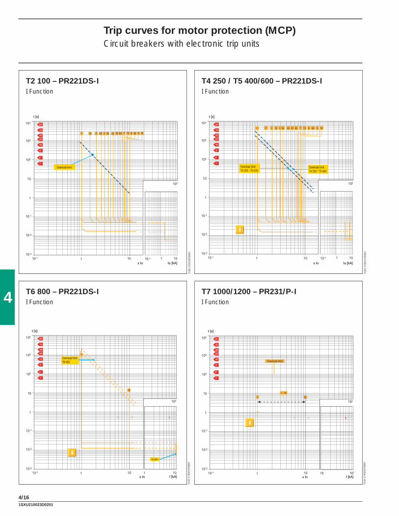
4/16
1SD
C21
0U50
F000
1
1SD
C21
0U51
F000
1
t [s]
1I [kA]
10
10-1
10-2
1
10
102
103
104
10-110-3
10x In
102
1
T6 800
1
10
t [s]
1I [kA]
10
10-1
10-2
1
10
102
103
104
10-110-3
102
x In
102
10
1 12
Overload limit
1...10
1SD
C21
0U52
F000
1
1SD
C21
0Q02
F000
1
Overload limit Overload limitT4 320 - T5 630
Overload limitT4 250 - T5 400
Overload limitT6 800
4
Trip curves for motor protection (MCP)Circuit breakers with electronic trip units
T2 100 – PR221DS-II Function
T4 250 / T5 400/600 – PR221DS-II Function
T6 800 – PR221DS-II Function
T7 1000/1200 – PR231/P-I I Function
1SXU210023D0201

4/17
1SD
C21
0Q03
F000
1
1SD
C21
0Q04
F000
1
1SD
C21
0Q05
F000
1
1Irms [kA]
10 102
1
10I2t [106 A2s]
10-1
1Irms [kA]
10 102
1
10I2t [106 A2s]
10-1
1SD
C21
0Q06
F000
1
1Irms [kA]
10 102
1
10I2t [106 A2s]
10-1
1Irms [kA]
10 102
1
10I2t [106 A2s]
10-1
4
Specifi c let-through energy curves (current limiting circuit breakers)
T2 H PR221 100A480 V
T2 H TM 100A480 V
T2 H TM 50A480 V
T2 H TM 30A480 V
1SDC210023D0201

4/18
1Irms [kA]
10 102
1
10I2t [106 A2s]
10-1
Irms [kA]10 103
1
10I2t [106 A2s]
10-1
10 2
1SD
C21
0Q07
F000
1
1SD
C21
0Q08
F000
1
Irms [kA]10 103
1
10I2t [106 A2s]
10-1
10 2
Irms [kA]10 103
1
10I2t [106 A2s]
10-1
10 2
1SD
C21
0Q09
F000
1
1SD
C21
0Q10
F000
1
4
Specifi c let-through energy curves (current limiting circuit breakers)
T2 H TM 15A480 V
T4 H/V480 V
T4 H/V600 V
T5 400 H/V480 V
1SXU210023D0201

4/19
1SD
C21
0Q11
F000
1
Irms [kA]10 103
1
10I2t [106 A2s]
10-1
10 2
4
T5 400 H/V600 V
1SXU210023D0201

4/20
1SD
C21
0Q00
F000
1
1SD
C21
0Q12
F000
1
1SD
C21
0Q13
F000
1
1Irms [kA]
10 1021
10
Ip [kA]
102
1Irms [kA]
10 1021
10
Ip [kA]
102
1SD
C21
0Q14
F000
1
1Irms [kA]
10 1021
10
Ip [kA]
102
1Irms [kA]
10 1021
10
Ip [kA]
102
T2 H PR221 100A480 V
T2 H TM 100A480 V
T2 H TM 50A480 V
T2 H TM 30A480 V4
Limitation curves (current limiting circuit breakers)
1SXU210023D0201

4/21
4
1Irms [kA]
10 1021
10
Ip [kA]
102
Irms [kA]10 10310 2
1
10
102
Ip [kA]
1SD
C21
0Q15
F000
1
1SD
C21
0Q16
F000
1
Irms [kA]10 10310 2
1
10
102
Ip [kA]
Irms [kA]10 10310 2
1
10
102
Ip [kA]
1SD
C21
0Q17
F000
1
1SD
C21
0Q18
F000
1
T2 H TM 15A480 V
T4 H/V480 V
T4 H/V600 V
T5 400 H/V480 V
1SDC210023D0201
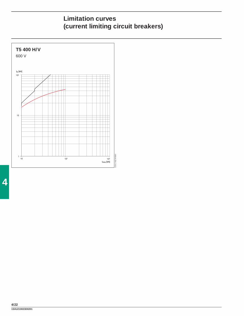
4/22
1SD
C21
0Q19
F000
1
Irms [kA]10 10310 2
1
10
102
Ip [kA]
T5 400 H/V600 V
4
Limitation curves (current limiting circuit breakers)
1SXU210023D0201

4/23
95/35Ambient temperature [°F/°C]
104/40 113/45 122/50 131/55 140/60 149/65 158/700.6
0.65
0.7
0.75
0.8
0.85
0.9
0.95
1
1.05
Imax [xIn]
4
Temperature performancesCircuit breakers with electronic trip unit
PR221DSPR222DS/PPR231/PPR232/PPR331/PPR332/P
1SD
C21
0U00
F000
1
1SXU210023D0201

4/24
4
Temperature performancesCircuit breakers with thermal magnetic trip units
Tmax T1 and T1 1P
In [A] 50 °F / 10 °C 68 °F / 20 °C 86 °F / 30 °C 104 °F / 40 °C 122 °F / 50 °C 140 °F / 60 °C
15 18 17 16 15 14 1320 24 22 21 20 19 1725 29 28 27 25 23 2230 35 34 32 30 28 2640 47 45 43 40 37 3450 60 57 53 50 46 4260 71 68 64 60 56 5170 83 79 75 70 65 6080 94 90 85 80 75 6990 106 101 96 90 84 78100 121 114 107 100 92 84
Tmax T2
In [A] 50 °F / 10 °C 68 °F / 20 °C 86 °F / 30 °C 104 °F / 40 °C 122 °F / 50 °C 140 °F / 60 °C
15 18 17 16 15 14 1220 24 23 21 20 18 1725 30 28 27 25 23 2130 35 33 32 30 28 2635 40 39 37 35 33 3140 46 44 42 40 38 3550 56 54 52 50 48 4560 71 68 64 60 56 5170 83 79 75 70 65 6080 96 91 86 80 74 6790 109 103 97 90 83 75100 115 110 105 100 95 89
Tmax T3
In [A] 50 °F / 10 °C 68 °F / 20 °C 86 °F / 30 °C 104 °F / 40 °C 122 °F / 50 °C 140 °F / 60 °C
60 70 67 64 60 56 5270 82 78 74 70 66 6180 92 88 84 80 75 7190 104 100 95 90 85 79100 117 112 106 100 94 87125 145 139 132 125 118 110150 175 167 159 150 141 131175 205 195 185 175 164 152200 236 224 213 200 187 172225 264 251 239 225 211 195
1SXU210023D0201

4/25
4Tmax T4
In [A] 50 °F / 10 °C 68 °F / 20 °C 86 °F / 30 °C 104 °F / 40 °C 122 °F / 50 °C 140 °F / 60 °C
20 24 22 21 20 19 1725 30 28 27 25 23 2140 47 44 42 40 37 3450 59 56 53 50 47 4380 94 90 85 80 75 68100 118 112 106 100 95 85125 148 140 133 125 119 106150 177 168 159 150 143 127200 236 224 212 200 190 170250 266 252 239 225 214 191
Tmax T5 400/600
In [A] 50 °F / 10 °C 68 °F / 20 °C 86 °F / 30 °C 104 °F / 40 °C 122 °F / 50 °C 140 °F / 60 °C
300 241…345 230…328 220…314 210…300 200…286 187…267400 325…465 310…442 295…420 280…400 265…380 250…355600 483…690 459…656 440…628 420…600 400…572 374…534
Tmax T6 800
In [A] 50 °F / 10 °C 68 °F / 20 °C 86 °F / 30 °C 104 °F / 40 °C 122 °F / 50 °C 140 °F / 60 °C
600 520…740 493…705 462…660 441…630 405…580 380…540800 685…965 640…905 605…855 560…800 520…740 470…670
Tmax Ts3 150
In [A] 50 °F / 10 °C 68 °F / 20 °C 86 °F / 30 °C 104 °F / 40 °C 122 °F / 50 °C 140 °F / 60 °C
15 18 17 16 15 14 1320 24 22 21 20 19 1725 30 28 27 25 23 2130 35 33 32 30 28 2635 41 39 37 35 33 3040 47 44 42 40 37 3450 59 56 53 50 47 4360 71 67 64 60 56 5170 83 78 74 70 66 6080 94 90 85 80 75 6890 106 101 95 90 85 77100 118 112 106 100 95 85125 148 140 133 125 119 106150 177 168 159 150 143 127
Tmax Ts3 225
In [A] 50 °F / 10 °C 68 °F / 20 °C 86 °F / 30 °C 104 °F / 40 °C 122 °F / 50 °C 140 °F / 60 °C
175 207 196 186 175 166 149200 236 224 212 200 190 170225 266 252 239 225 214 191
1SXU210023D0201

4/26
4
Power losses
Type Trip unit In [A] P [W/pole]
T1 - T1B 1p TMF
15 1.320 1.325 2.030 1.840 2.650 3.760 3.970 5.380 4.890 6.1100 6.8
T2
TMF
15 1.020 1.725 1.630 2.435 3.040 2.850 3.260 4.670 4.780 5.490 6.9100 7.7
ELT
10 0.525 1.063 3.5100 8.0
T3 TMF
60 3.970 4.280 4.890 5.0100 5.3125 6.6150 7.4175 11.6200 13.2225 15.0
Ts3 TMF
15 3.220 3.225 3.330 3.535 4.840 6.350 5.360 7.770 4.680 6.090 7.6100 7.0125 6.7150 8.8175 9.2200 12.0225 13.5
1SXU210023D0201

4/27
4
Type Trip unit In [A] P [W/pole]
T4
TMF15 3.620 3.6
TMD30 3.640 3.850 3.980 4.6100 5.2
TMA 125 5.7150 6.9200 9.9250 13.7
ELT100 1.7150 3.9200 10.7
T5
TMA300 12.3400 19.5600 40.1
ELT300 9.3400 16.5600 37.1
T6TMA
600 30.6800 31
ELT600 30800 32
T7 ELT
400 5600 12800 19.31000 301200 47
1SXU210023D0201
5
5/1
Wiring diagrams
Index
Information for reading - Circuit breakers T1, T2, T3, T4, T5, T6 ...................................................5/2
Information for reading - Circuit breakers Ts3 ................................................................................5/6
Information for reading - Circuit breakers T7 .................................................................................5/8
Information for reading - ATS010 for Ts3-T4-T5-T6 .....................................................................5/12
Information for reading - ATS010 for T7 .......................................................................................5/13
Graphic symbols (IEC 60617 and CEI 3-14...3-26 Standards) .....................................................5/14
Wiring diagram of the T1, T2, T3, T4, T5, T6 circuit breakers ......................................................5/15
Wiring diagram of the Ts3 circuit breakers ...................................................................................5/17
Wiring diagram of the T7 circuit breakers ....................................................................................5/18
Electrical accessories for T1, T2, T3, T4, T5, T6 ..........................................................................5/20
Electrical accessories for Ts3 .......................................................................................................5/25
Electrical accessories for T7 ........................................................................................................5/26
Automatic transfer-switch ATS010 for T4-T5-T6 ..........................................................................5/30
Automatic transfer-switch ATS010 for T7.....................................................................................5/34
1SXU210023D0201

5
5/2
Wiring diagramsInformation for reading - Circuit breakers T1, T2, T3, T4, T5, T6
State of operation representedThe diagram is shown in the following conditions:– plug-in version circuit breaker open and racked-in– contactor for motor starting open– circuits de-energised– trip units not tripped– motor operator with springs charged.
VersionThe diagram shows a circuit breaker or switch-disconnector in the plug-in version (only T2, T3, T4 and T5) or in the draw out version (T6). The diagram is also valid for the fi xed and draw out version circuit breakers or switch-disconnectors.With the fi xed version circuit breakers or switch-disconnectors, the applications indicated in fi gures 26-27-28-29-30-31 and 32 cannot be provided.
Caption = Figure number of the diagram
* = See note indicated by the letterA1 = Circuit breaker applications A11 = FDU interfacing unit (front display) A12 = AUX-E type signalling unit, with auxiliary relays for electrical signalling of circuit
breaker open and circuit breaker trippedA13 = PR021/K type signalling unit, with auxiliary relays for electrical signalling of the
protection functions of electronic trip unitA14 = MOE-E type actuation unit, with auxiliary relays for carrying out the commands
coming from the dialogue unitA15 = PR212/CI type contactor control unit for motor startingA16 = Solenoid operating mechanismA17 = Unit for M motor electrical latching A18 = VM210 type voltage measuring unit A2 = Applications of the solenoid operator or motor operatorA3 = Applications of the RC221, RC222 or RC223 type residual current releaseA4 = Indication apparatus and connections for control and signalling, outside the circuit breakerD = Electronic time-delay device of the undervoltage release (outside the circuit breaker)H, H1 = Signalling lampsK = Contactor for motor startingK51 = Electronic trip unit:
– PR221 type overcurrent release, with the following protection functions: - L against overload with inverse long time delay - S against short-circuit with inverse or defi nite short time delay - I against short-circuit with instantaneous trip– PR222DS/P, PR222DS/PD-A, type overcurrent release, with the following protec-
tion functions: - L against overload with inverse long time delay - S against short-circuit with inverse or defi nite short time delay - I against short-circuit with instantaneous trip time - G against ground fault with short time trip– PR222MP motor protection type trip unit, with the following protection functions: - against overload (thermal protection) - against rotor block - against short-circuit - against missing or unbalanced current between the phases
K51/1…8 = Contact for electrical signalling of the protection functions of the electronic trip unitK87 = RC221, RC222 or RC223 type residual current trip unit
1SXU210023D0201

5
5/3
M = Motor for circuit breaker opening and circuit breaker closing spring chargingM1 = Three-phase asynchronous motorQ = Main circuit breakerQ/0,1,2,3 = Auxiliary circuit breaker contacts R = Resistor (see note F)R1 = Motor thermistorR2 = Thermistor in the motor operatorS1, S2 = Contacts controlled by the cam of the motor operatorS3, S3/1 = Change-over contact for electrical signalling of local/remote selector statusS4/1-2 = Contacts activated by the circuit breaker rotary handle (see note C)S51/S = Contact for electrical signalling of overload in progress (start)S75I/1…3 = Contacts for electrical signalling of circuit breaker in racked-in position (only
provided with circuit breakers in plug-in and draw out version)S75S/1…3 = Contacts for electrical signalling of circuit breaker in racked-out position (only provided with circuit breakers in plug-in and draw out version)S87/1 = Contact for electrical signalling of RC222 or RC223 type residual current release
pre-alarmS87/2 = Contact for electrical signalling of RC222 Change-over contact for electrical signal-
ling of local/remote selector status type residual current release alarmS87/3 = Contact for electrical signalling of circuit breaker open due to RC221, RC222 or
RC223 type residual current release tripSC = Pushbutton or contact for closing the circuit breakerSC3 = Pushbutton for motor startingSD = Switch-disconnector of the power supply of the RC221 or RC222 type residual
current releaseSO = Pushbutton or contact for opening the circuit breakerSO1, SO2 = Pushbuttons or contacts for the circuit breaker opening (see Resetting instructions for circuit breaker tripped by trip units)SO3 = Pushbutton for stopping the motorSQ = Contact for electrical signalling of circuit breaker openSY = Contact for electrical signalling of circuit breaker open due to YO, YO1, YO2 or YU
thermomagnetic trip unit intervention (bell alarm)TI = Toroidal current transformerTI/L1 = Current transformer placed on phase L1TI/L2 = Current transformer placed on phase L2TI/L3 = Current transformer placed on phase L3TI/N = Current transformer placed on the neutralW1 = Serial interface with the control system (EIA RS485 interface. See note D)X1,X2,X5…X9 = Connectors for the circuit breaker auxiliary circuits (in the case of circuit breakers
in plug-in version, removal of the connectors takes place simultaneously with that of the circuit breaker. See note E)
X11 = Back-up terminal boxX3,X4 = Connectors for the circuits of the electronic trip unit (in the case of cir-
cuit breakers in the plug-in version, removal of the connectors takes place simultaneously with that of the circuit breaker)
XA = Interfacing connector of the PR222DS/P, PR222DS/PD-A trip unitXA1 = Three-way connector for YO/YU (see note E)XA10 = Six-way connector for solenoid operatorXA2 = Twelve-way connector for auxiliary contacts (see note E)XA5 = Three-way connector for contact of electrical signalling of circuit breaker open due
to trip of the RC221, RC222 or RC223 type residual current release (see note E)XA6 = Three-way connector for contact of electrical signalling of circuit breaker open due
to trip of the overcurrent release (see note E)XA7 = Six-way connector for auxiliary contacts (see note E)XA8 = Six-way connector for contacts operated by the rotary handle or for the motor
operator (see note E)XA9 = Six-way connector for the electrical signalling of RC222 or RC223 type residual
current release pre-alarm and alarm and for opening by means of the release itself (see note E)
1SXU210023D0201

5
5/4
Wiring diagramsInformation for reading - Circuit breakers T1, T2, T3, T4, T5, T6
XB,XC,XE = Interfacing connectors of the AUX-E unitXD = Interfacing connector of the FDU unitXF = Interfacing connector of the MOE-E unitX0 = Connector for the YO1 trip coilX01 = Connector for the YO2 trip coilXV = Terminal boxes of the applicationsYC = Closing release of the motor operating mechanismYO = Opening releaseYO1 = Trip coil of the electronic trip unitYO2 = Trip coil of the RC221, RC222 or RC223 type residual current releaseYO3 = Shunt trip of the solenoid operatorYU = Undervoltage release (see note B).
Description of fi guresFig. 1 = Opening release.Fig. 2 = Permanent opening release.Fig. 3 = Instantaneous undervoltage release (see note B and F).Fig. 4 = Undervoltage release with electronic time-delay device outside the circuit breaker (see note B).Fig. 5 = Instantaneous undervoltage release in version for machine tools with one contact in series
(see note B, C, and F).Fig. 6 = Instantaneous undervoltage release in version for machine tools with two contacts in series
(see note B, C, and F).Fig. 7 = One changeover contact for electrical signalling of circuit breaker open due to RC221, RC222
or RC223 type residual current release trip.Fig. 8 = RC222 or RC223 type residual current release circuits.Fig. 9 = Two electrical signalling contacts for RC222 or RC223 type residual current release pre-alarm
and alarm.Fig. 10 = Solenoid operator.Fig. 11 = Stored energy motor operator.Fig. 12 = Local/remote auxiliary contact for stored-energy motor operating mechanism.Fig. 21 = Three changeover contacts for electrical signalling of circuit breaker open or closed and one
changeover contact for electrical signalling of circuit breaker open due to YO, YO1, YO2 and YU thermomagnetic trip unit intervention (tripped position).
Fig. 22 = One changeover contact for electrical signalling of circuit breaker open or closed and a changeover contact for electrical signalling of circuit breaker open due to YO, YO1, YO2 or YU the thermomagnetic trip unit intervention (tripped position).
Fig. 23 = Two changeover contacts for electrical signalling of circuit breaker open or closed.Fig. 24 = One changeover contact for electrical signalling of circuit breaker open due to overcurrent
release trip (T2).Fig. 25 = One contact for electrical signalling of circuit breaker open due to overcurrent release trip
(T4-T5-T6).Fig. 26 = First position of circuit breaker changeover contact, for electrical signalling of racked-in.Fig. 27 = Second position of circuit breaker changeover contact, for electrical signalling of racked-in.Fig. 28 = Third position of circuit breaker changeover contact, for electrical signalling of racked-in.Fig. 29 = First position of circuit breaker changeover contact, for electrical signalling of isolated.Fig. 30 = Second position of circuit breaker changeover contact, for electrical signalling of isolated.Fig. 31 = Third position of circuit breaker changeover contact, for electrical signalling of isolated.Fig. 32 = Circuit of the current transformer on neutral conductor outside the circuit breaker (for plug-in
and draw out version circuit breaker).Fig. 41 = Auxiliary circuits of the PR222DS/P, PR222DS/PD-A electronic trip unit connected with FDU
front display unit.Fig. 42 = Auxiliary circuits of the PR222DS/PD-A electronic trip unit connected with PR021/K type
signalling unit.Fig. 43 = Auxiliary circuits of the PR222DS/PD-A electronic trip unit connected with FDU front display
unit and with PR021/K type signalling unit.
1SXU210023D0201
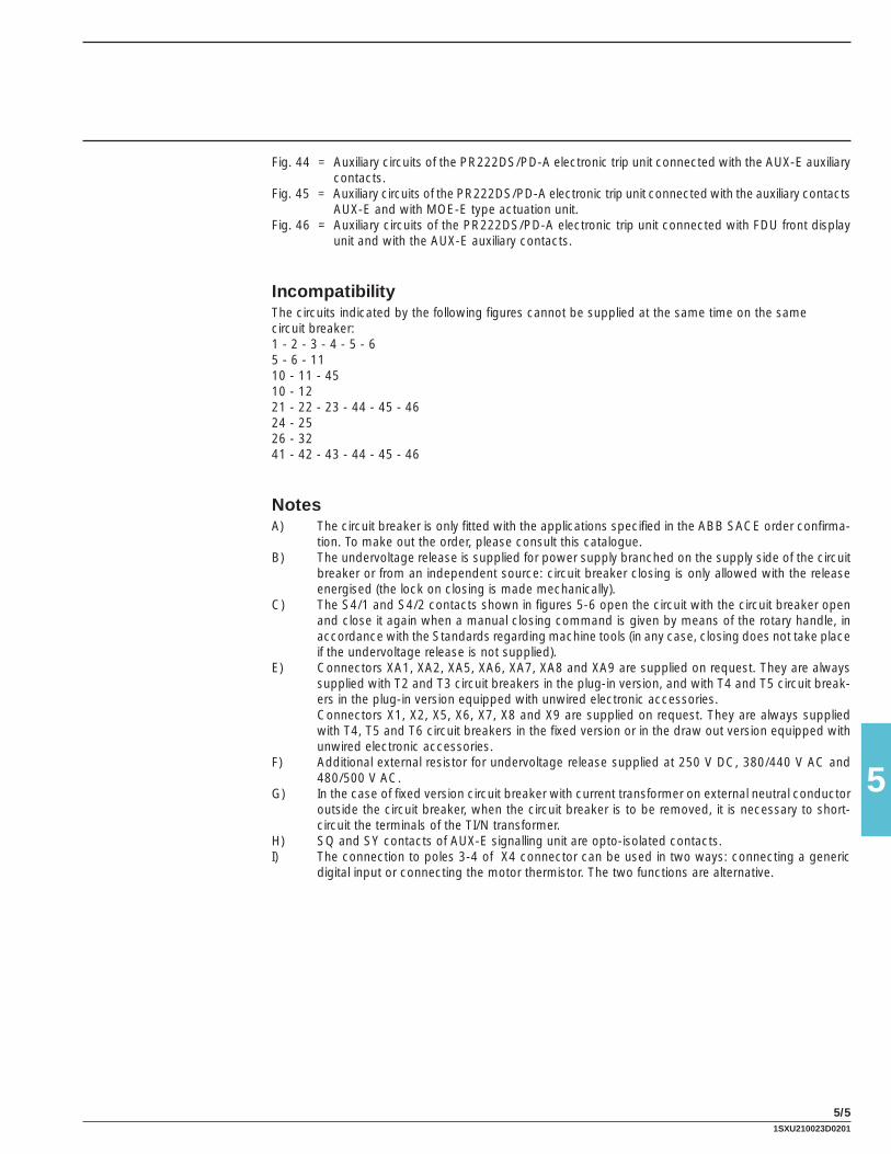
5
5/5
Fig. 44 = Auxiliary circuits of the PR222DS/PD-A electronic trip unit connected with the AUX-E auxiliary contacts.
Fig. 45 = Auxiliary circuits of the PR222DS/PD-A electronic trip unit connected with the auxiliary contacts AUX-E and with MOE-E type actuation unit.
Fig. 46 = Auxiliary circuits of the PR222DS/PD-A electronic trip unit connected with FDU front display unit and with the AUX-E auxiliary contacts.
IncompatibilityThe circuits indicated by the following fi gures cannot be supplied at the same time on the samecircuit breaker:1 - 2 - 3 - 4 - 5 - 65 - 6 - 1110 - 11 - 4510 - 1221 - 22 - 23 - 44 - 45 - 4624 - 2526 - 3241 - 42 - 43 - 44 - 45 - 46
NotesA) The circuit breaker is only fi tted with the applications specifi ed in the ABB SACE order confi rma-
tion. To make out the order, please consult this catalogue.B) The undervoltage release is supplied for power supply branched on the supply side of the circuit
breaker or from an independent source: circuit breaker closing is only allowed with the release energised (the lock on closing is made mechanically).
C) The S4/1 and S4/2 contacts shown in fi gures 5-6 open the circuit with the circuit breaker open and close it again when a manual closing command is given by means of the rotary handle, in accordance with the Standards regarding machine tools (in any case, closing does not take place if the undervoltage release is not supplied).
E) Connectors XA1, XA2, XA5, XA6, XA7, XA8 and XA9 are supplied on request. They are always supplied with T2 and T3 circuit breakers in the plug-in version, and with T4 and T5 circuit break-ers in the plug-in version equipped with unwired electronic accessories.
Connectors X1, X2, X5, X6, X7, X8 and X9 are supplied on request. They are always supplied with T4, T5 and T6 circuit breakers in the fi xed version or in the draw out version equipped with unwired electronic accessories.
F) Additional external resistor for undervoltage release supplied at 250 V DC, 380/440 V AC and 480/500 V AC.
G) In the case of fi xed version circuit breaker with current transformer on external neutral conductor outside the circuit breaker, when the circuit breaker is to be removed, it is necessary to short-circuit the terminals of the TI/N transformer.
H) SQ and SY contacts of AUX-E signalling unit are opto-isolated contacts.I) The connection to poles 3-4 of X4 connector can be used in two ways: connecting a generic
digital input or connecting the motor thermistor. The two functions are alternative.
1SXU210023D0201
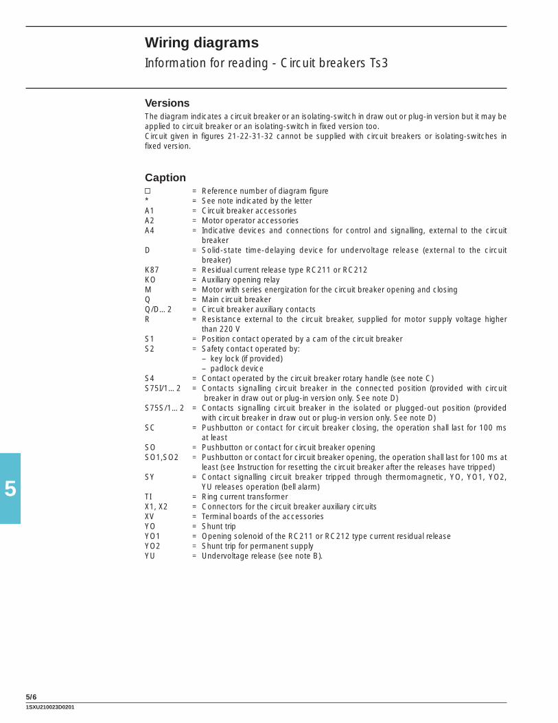
5
5/6
VersionsThe diagram indicates a circuit breaker or an isolating-switch in draw out or plug-in version but it may be applied to circuit breaker or an isolating-switch in fi xed version too.Circuit given in fi gures 21-22-31-32 cannot be supplied with circuit breakers or isolating-switches in fi xed version.
Caption = Reference number of diagram fi gure
* = See note indicated by the letterA1 = Circuit breaker accessoriesA2 = Motor operator accessoriesA4 = Indicative devices and connections for control and signalling, external to the circuit
breakerD = Solid-state time-delaying device for undervoltage release (external to the circuit
breaker)K87 = Residual current release type RC211 or RC212KO = Auxiliary opening relayM = Motor with series energization for the circuit breaker opening and closingQ = Main circuit breakerQ/D…2 = Circuit breaker auxiliary contactsR = Resistance external to the circuit breaker, supplied for motor supply voltage higher
than 220 VS1 = Position contact operated by a cam of the circuit breakerS2 = Safety contact operated by: – key lock (if provided) – padlock deviceS4 = Contact operated by the circuit breaker rotary handle (see note C)S75I/1…2 = Contacts signalling circuit breaker in the connected position (provided with circuit
breaker in draw out or plug-in version only. See note D)S75S/1…2 = Contacts signalling circuit breaker in the isolated or plugged-out position (provided
with circuit breaker in draw out or plug-in version only. See note D)SC = Pushbutton or contact for circuit breaker closing, the operation shall last for 100 ms
at leastSO = Pushbutton or contact for circuit breaker openingSO1,SO2 = Pushbutton or contact for circuit breaker opening, the operation shall last for 100 ms at
least (see Instruction for resetting the circuit breaker after the releases have tripped)SY = Contact signalling circuit breaker tripped through thermomagnetic, YO, YO1, YO2,
YU releases operation (bell alarm)TI = Ring current transformerX1, X2 = Connectors for the circuit breaker auxiliary circuitsXV = Terminal boards of the accessoriesYO = Shunt tripYO1 = Opening solenoid of the RC211 or RC212 type current residual releaseYO2 = Shunt trip for permanent supplyYU = Undervoltage release (see note B).
Wiring diagramsInformation for reading - Circuit breakers Ts3
1SXU210023D0201

5
5/7
Description of fi guresFig. 1 = Shunt tripFig. 2 = Opening solenoid of the RC211 type residual current releaseFig. 3 = Opening solenoid of the RC212 type residual current releaseFig. 4 = Instantaneous undervoltage release (see note B)Fig. 5 = Instantaneous undervoltage release in version for machine tools (see notes B and C)Fig. 6 = Undervoltage release with solid-state time-delaying device external to the circuit breaker
(see note B)Fig. 7 = Direct-acting motor operatorFig. 8 = Shunt trip for permanent supplyFig. 11 = Two change-over contacts signalling circuit breaker on/offFig. 12 = One change-over contact signalling circuit breaker on/off and one change-over contact
signalling circuit breaker tripped through thermomagnetic YO, YO1, YO2, YU releases operation (bell alarm)
Fig. 21 = First circuit breaker position contact, signalling the connected position (see note D)Fig. 22 = Second circuit breaker position contact, signalling the connected position (see note D)Fig. 31 = First circuit breaker position contact, signalling the isolated or plugged-out position (see
note D)Fig. 32 = Second circuit breaker position contact, signalling the isolated or plugged-out position
(see note D).
IncompatibilityThe combinations of circuits given in the fi gures below are not possible on the same circuit breaker:2 - 31 - 4 - 5 - 6 - 7 - 811 - 1221 - 3122 - 32
NotesA) Circuit breaker is delivered complete with the accessories listed in the ABB order acknowledge-
ment only.B) Undervoltage release is suitable for circuit breaker supply side feeding or for feeding from an independent
source: circuit breaker closes only if the undervoltage release is energized (lock on closing is achieved mechanically).
C) Contact S4 given in fi g. 5 opens the circuit when the circuit breaker is open and it closes when a manual closing control is carried out through rotary handle, in compliance with the Standards relevant to the machine tools (the closing does not occur indeed if the undervoltage release is not energized).
D) Circuit breaker can be equipped with S75I and S75S position contacts, in whatever combination, with a maximum of 2 total contacts.
1SXU210023D0201

5
5/8
Wiring diagramsInformation for reading - Circuit breakers T7
WarningBefore installing the circuit breaker, carefully read notes F and O on the circuit diagrams.
Operating status shownThe circuit diagram is for the following conditions:– draw out circuit breaker, open and racked-in– circuits de-energised– releases not tripped– motor operating mechanism with springs discharged.
Versions Though the diagram shows a circuit breaker in draw out version, it can be applied to a fi xed version circuit breaker as well.
Fixed versionThe control circuits are fi tted between terminals XV (connectors X12-X13-X14-X15 are not supplied).With this version, the applications indicated in fi gure 31A cannot be provided.
Draw out versionThe control circuits are fi tted between the poles of connectors X12-X13-X14-X15 (terminal box XV is not supplied).
Version without overcurrent releaseWith this version, the applications indicated in fi gures 13A, 14A, 41A, 42A, 43A, 44A, 45A, 62A cannot be provided.
Version with PR231/P or PR232/P electronic trip unitWith this version, the applications indicated in fi gures 41A, 42A, 43A, 44A, 45A, 62A cannot be pro-vided.
Version with PR331/P electronic trip unitWith this version, the applications indicated in fi gures 42A, 43A, 44A, 45A cannot be provided.
Version with PR332/P electronic trip unitWith this version, the applications indicated in fi gure 41A cannot be provided.
Caption = Circuit diagram fi gure number
* = See note indicated by letterA1 = Circuit breaker accessoriesA3 = Accessories applied to the cradle of the circuit breaker (for draw out version only)A4 = Example switchgear and connections for control and signalling, outside the circuit
breakerA13 = PR021/K signalling unit (outside the circuit breaker)A19 = PR330/R actuation unitAY = SOR TEST UNIT Test/monitoring Unit (see note R)D = Electronic time-delay device of the undervoltage release, outside the circuitbreakerK51 = PR231/P, PR232/P, PR331/P, PR332/P type electronic trip unit with the following
protection functions: – L overload protection with inverse long time-delay trip - setting I1– S short-circuit protection with inverse or defi nite short time-delay trip - setting I2– I short-circuit protection with instantaneous time-delay trip - setting I3– G ground fault protection with inverse short time-delay trip - setting I4
K51/1...8 = Contacts of the PR021/K signalling unitK51/GZin (DBin) = Zone selectivity: input for protection G or “reverse” direction input for protection D
(only with Uaux. and PR332/P trip unit)
1SXU210023D0201

5
5/9
K51/GZout (DBout) = Zone selectivity: output for protection G or “reverse” direction output for protection D (only with and PR332/P trip unit)
K51/SZin (DFin) = Zone selectivity: input for protection S or “direct” input for protection D (only with Uaux. and PR332/P trip unit)
K51/SZout (DFout) = Zone selectivity: output for protection S or “direct” output for protection D (only with Uaux. and PR332/P trip unit)
K51/YC = Closing control from PR332/P electronic trip unit with communication module PR330/D-M and PR330/R actuation unit
K51/YO = Opening control from PR332/P electronic trip unit with communication module PR330/D-M and PR330/R actuation unit
M = Motor for charging the closing springsQ = Circuit breakerQ/1...6 = Circuit breaker auxiliary contactsS33M/1...3 = Limit contacts for spring-charging motorS4/1-2-3 = Contacts activated by the rotary handle of the circuit breaker – only for circuit break-
ers with manual control (see note C)S43 = Switch for setting remote/local controlS51 = Contact for electrical signalling of circuit breaker open due to tripping of the over-
current trip unit. The circuit breaker may be closed only after pressing the reset pushbutton, or after energizing the coil for electrical reset (if available)
S51/P1 = Programmable contact (as default it signals overload present - start)S75E/1...2 = Contacts for electrical signalling of circuit breaker in racked-out position (only with
draw out circuit breakers)S75I/1...7 = Contacts for electrical signalling of circuit breaker in racked-in position (only with
draw out circuit breakers)S75T/1..2 = Contacts for electrical signalling of circuit breaker in test isolated position (only with
draw out circuit breakers)SC = Pushbutton or contact for closing the circuit breakerSO = Pushbutton or contact for opening the circuit breakerSO1 = Pushbutton or contact for opening the circuit breaker with delayed tripSO2 = Pushbutton or contact for opening the circuit breaker with instantaneous tripSR = Pushbutton or contact for electrical circuit breaker resetSRTC = Contact for electrical signalling of circuit breaker open, with springs charged and
ready to close SY = Contact for electrical signalling of circuit breaker open due to trip units tripped, YO,
YO1, YO2, YU (bell alarm) only for circuit breakers with direct controlTI/L1 = Current transformer located on phase L1TI/L2 = Current transformer located on phase L2TI/L3 = Current transformer located on phase L3T0 = Homopolar Toroidal current transformer (see note T)TU = Insulating voltage transformerUaux. = Auxiliary power supply voltage (see note F)UI/L1 = Current sensor (Rogowski coil) located on phase L1UI/L2 = Current sensor (Rogowski coil) located on phase L2UI/L3 = Current sensor (Rogowski coil) located on phase L3UI/N = Current sensor (Rogowski coil) located on neutralUI/0 = Current sensor (Rogowski coil) located on the conductor connecting to ground the
star point of the MV/LV transformer (see note G)W1 = Serial interface with control system (external bus): EIA RS485 interface (see note E)W2 = Serial interface with the accessories of PR331/P and PR332/P trip units (internal
bus)X12…X15 = Delivery connectors for auxiliary circuits of draw out version circuit breaker XB1...XB7 = Connectors for the accessories of the circuit breakerXF = Delivery terminal box for the position contacts of the draw out circuit breaker (located
on the cradle of the circuit breaker)XO = Connector for YO1 releaseXR1 – XR2 = Connector for power circuits of PR231/P, PR232/P, PR331/P, and PR332/P trip
unitsXR5 – XR13 = Connector for power circuits of PR332/P trip unit
1SXU210023D0201

5
5/10
Wiring diagramsInformation for reading - Circuit breakers T7
XV = Delivery terminal box for the auxiliary circuits of the fi xed circuit breakerYC = Closing coilYO = Shunt tripYO1 = Overcurrent shunt trip (trip coil)YO2 = Second shunt trip (see note Q)YR = Coil to electrically reset the circuit breakerYU = Undervoltage release (see notes B, C and Q)
Description of fi gures Fig. 1A = Motor circuit to charge the closing springs.Fig. 2A = Circuit of closing coil.Fig. 4A = Shunt trip.Fig. 6A = Instantaneous undervoltage release (see notes B, C and Q).Fig. 7A = Undervoltage release with electronic time-delay device, outside the circuit breaker (see notes
B and Q).Fig. 8A = Second shunt trip (see note Q).Fig. 11A = Contact for electrical signalling of springs charged or discharged.Fig. 12A = Contact for electrical signalling of circuit breaker open, with springs charged, and ready to
close. Fig. 13A = Contact for electrical signalling of circuit breaker open due to tripping of the overcurrent
release. The circuit breaker may be closed only after pressing the reset pushbutton, or after energizing the coil for electronic reset (if available).
Fig. 14A = Electrical reset control.Fig. 15A = Contact operated by the circuit breaker rotary handle – for circuit breakers with manual
control only (see note C).Fig. 21A = Circuit breaker auxiliary contacts (for circuit breakers with manual control only).Fig. 22A = Circuit breaker auxiliary contacts (for circuit breakers with motor control only).Fig. 31A = First set of contacts for electrical signalling of circuit breaker in racked-in, test isolated,
racked out position.Fig. 41A = Auxiliary circuits of PR331/P trip unit (see note F).Fig. 42A = Auxiliary circuits of PR332/P trip units (see notes F and N).Fig. 43A = Circuits of the measuring module PR330/V of the PR332/P trip units internally connected
to the circuit breaker (optional).Fig. 44A = Circuits of the measuring module PR330/V of the PR332/P trip units externally connected
to the circuit breaker (optional; see note O).Fig. 45A = Circuits of the PR332/P trip unit with communication module PR330/D-M connected to
PR330/V actuation unit (see notes E, F and N).Fig. 46A = Circuits of the PR332/P trip unit PR330/V measuring module connected internally to the
three-pole circuit breaker with external neutral conductor (optional)Fig. 61A = SOR TEST UNIT Test/monitoring unit (see note R).Fig. 62A = Circuits of the PR021/K signalling module (outside the circuit breaker).
IncompatibilitiesThe circuits indicated in the following fi gures cannot be supplied simultaneously on the same circuit breaker:6A - 7A - 8A21A - 22A41A - 42A - 45A43A - 44A - 46A
1SXU210023D0201

5
5/11
NotesA) The circuit breaker is only fi tted with the applications specifi ed in the ABB SACE order confi rma-
tion. To make out the order, please consult this catalogue.B) The undervoltage release is supplied for operation using a power supply branched on the sup-
ply side of the circuit breaker or from an independent source. The circuit breaker can only close when the release is energized (there is a mechanical lock on closing).
C) In conformity with the Standards governing machine tools, contacts S4 shown in Fig. 15A can be used to open the Yu undervoltage release circuit (Fig. 6A) when the circuit breaker is open and close it again upon a manual closing command from the rotary handle.
E) For the EIA RS485 serial interface connection see document RH0298 regarding MODBUS com-munication.
F) The auxiliary voltage Vaux allows actuation of all operations of the PR331/P, PR332/P and trip units.
Having requested a Vaux insulated from ground, one must use “galvanically separated con-verters” in compliance with IEC 60950 (UL 1950) or equivalent standards that ensure a com-mon mode current or leakage current (see IEC 478/1, CEI 22/3) not greater than 3.5 mA, IEC 60364-41 and CEI 64-8.
G) Ground fault protection is available with the PR332/P trip unit by means of a current sensor located on the conductor connecting to ground the star centre of the MV/LV transformer.
The connections between terminals 1 and 2 (or 3) of current transformer UI/O and poles T7 and T8 of the X (or XV) connector must be made with a two-pole shielded and stranded cable (see user manual), no more than 15 m long. The shield must be grounded on the circuit breaker side and current sensor side.
N) With PR332/P trip unit, the connections to the zone selectivity inputs and outputs must be made with a two-pole shielded and stranded cable (see user manual), no more than 300 m long. The shield must be grounded on the selectivity input side.
O) Systems with rated voltage greater than 690V require the use of an insulation voltage transformer to connect to the busbars.
P) With PR332/P trip unit with communication module PR330/D-M, the coils YO and YC can be controlled directly from contacts K51/YO and K51/YC with maximum voltages of 110-120 V DC e 240-250 V AC.
Q) The second opening release may be installed as an alternative to the undervoltage release.R) The SACE SOR TEST UNIT + opening release (YO) is guaranteed to operate starting at 75% of
the Vaux of the opening release itself. While the YO power supply contact is closing (short-circuit on terminals 4 and 5), the SACE SOR
TEST UNIT is unable to detect the opening coil status. Consequently: – For continuously powered opening coil, the TEST FAILED and ALARM signals will be
activated – If the coil opening command is of the pulsing type, the TEST FAILED signal may appear
at the same time. In this case, the TEST FAILED signal is actually an alarm signal only if it remains lit for more than 20s.
S) The connection cable shield must only be grounded on the circuit breaker side.T) The connections between the TO toroidal transformer and the poles of the X13 (or XV) connec-
tor of the circuit breaker must be made using a four-pole shielded cable with paired braided conductors (BELDEN 9696 paired type), with a length of not more than 15 m. The shield must be grounded on the circuit breaker side.
1SXU210023D0201

5
5/12
State of operation representedThe circuit diagram is for the following conditions:– circuit breakers open and connected – circuit breakers de-energized– closing springs discharged– overcurrent relays not tripped *# The present diagram shows draw out circuit breakers, but is also valid for fi xed circuit breakers: con-
nect terminal 17 to 20 and terminal 35 to 38 on the ATS010 device.* The present diagram shows circuit breakers with overcurrent trip unit (T4-T5), but is also valid for circuit
breakers with thermomagnetic trip unit and to circuit breakers with out relay (switch-disconnectors): connect terminal 18 to 20 and terminal 35 to 37 of the ATS010 device.
@ The present diagram shows four-pole circuit breakers but is also valid for two-pole circuit breakers: use only terminals 26 and 24 (phase and neutral) for the voltage connection of the normal power supply to the ATS010 device; also use the Q61/2 two-pole rather than four-pole auxiliary protection circuit breaker.
CaptionA = Device type ATS010 for the automatic transfer switch of two circuit breakersA17 = Unit for M motor electrical latchingK1 = Auxiliary contactor type VB6-30-01 for the emergency supply voltage presenceK2 = Auxiliary contactor type VB6-30-01 for the normal supply voltage presenceK51/Q1 = Overcurrent release for emergency supply line*K51/Q2 = Overcurrent release for normal supply line*KC1-KC2 = Auxiliary contactors type BC6-30 for circuit breaker closingKO1-KO2 = Auxiliary contactors type BC6-30 for circuit breaker openingM = Motor with series energization for the circuit breaker opening and closingQ/1 = Circuit breaker auxiliary contactQ1 = Circuit breaker for emergency supply lineQ2 = Circuit breaker for normal supply lineQ61/1-2 = Miniature circuit breakers for auxiliary circuits protection @S1, S2 = Position contact operated by a cam of the operating mechanismS3 = Key lock contact operated by the remote opening trip unit or the operating mecha-
nismS11…S16 = Contacts for the ATS010 device inputsS75I/1 = Contact signalling circuit breaker in draw out version connected #SY = Contact signalling circuit breaker tripped through trip units operation (bell alarm)*TI/… = Current trasformers feeding the overcurrent relayX2 = Connector for the circuit breaker auxiliary circuitsXV = Terminal boards of the accessories.
Wiring diagramsInformation for reading - ATS010 for T4-T5-T6
1SXU210023D0201

5
5/13
State of operation representedThe circuit diagrams are for the following conditions:– circuit breakers open and connected– circuits de-energized– closing springs discharged– overcurrent relays not tripped *– ATS010 not powered– generator in automatic mode, not started– transfer switch enabled– generator not in alarm– logic enabling command on (terminal 47).# The present diagram shows draw out circuit breakers, but is also valid for fi xed circuit breakers: cir-
cuit breaker auxiliary circuits are not connected to X12-X15 connectors but to the XV terminal board; furthermore connect terminal 17 to 20 and terminal 35 to 38 on the ATS010 device.
* The present diagram shows circuit breakers with overcurrent trip unit, but is also valid for circuit break-ers with thermomagnetic trip unit and to circuit breakers with out relay (switch-disconnectors): connect terminal 18 to 20 and terminal 35 to 37 of the ATS010 device.
@ The present diagram shows four-pole circuit breakers but is also valid for two-pole circuit breakers: use only terminals 26 and 24 (phase and neutral) for the voltage connection of the normal power supply to the ATS010 device; also use the Q61/2 two-pole rather than four-pole auxiliary protection circuit breaker.
CaptionA = Device type ATS010 for the automatic transfer switch of two circuit breakersK1 = Auxiliary contactor type VB6-30-01 for the emergency supply voltage presenceK2 = Auxiliary contactor type VB6-30-01 for the normal supply voltage presenceK51/Q1 = Overcurrent release for emergency supply line*K51/Q2 = Overcurrent release for normal supply line*KC1-KC2 = Auxiliary contactors type BC6-30 for circuit breaker closingKO1-KO2 = Auxiliary contactors type BC6-30 for circuit breaker openingM = Motor with series energization for the circuit breaker opening and closingQ/1 = Circuit breaker auxiliary contactQ1 = Circuit breaker for emergency supply lineQ2 = Circuit breaker for normal supply lineQ61/1-2 = Miniature circuit breakers for auxiliary circuits protection @S11…S16 = Contacts for the ATS010 device inputsS33M/1 = Limit switch of the closing springsS51 = Contact signalling circuit breaker tripped through the overcurrent relay *S75I/1 = Contact signalling circuit breaker in draw out version connected #TI/… = Current transformers feeding the overcurrent relayX12-X15 = Connectors fort he auxiliary circuits of the circuit breaker in draw out versionXF = Terminal board fort he position contacts of the draw out circuit breakerXV = Terminal boards of the accessories.YC = Closing coilYO = Shunt trip
NoteA) For the auxiliary circuits of the circuit breakers see the relative diagrams. The applications indi-
cated in the following fi gures are compulsory: 1A - 2A - 4A - 13A (only if the overcurrent release is supplied) - 22A - 31A (only for draw out version circuit breakers).
Wiring diagramsInformation for reading - ATS010 for T7
1SXU210023D0201

5
5/14
Wiring diagramsGraphic symbols (IEC 60617 and CEI 3-14...3-26 Standards)
M
M
Position switch (limit switch), break contact
Position switch (limit switch) change-over break before make contact
Contactor (contact open in the unoperated position)
Circuit-breaker disconnec-tor with automatic trip unit
Switch-disconnector (on-load isolating switch)
Operating device (general symbol)
Thermal relay
Instantaneous overcurrent or rate-of-rise relay
Overcurrent relay with adjustable short time-lag characteristic
Overcurrent relay with inverse short time-lag characteristic
Overcurrent relay with inverse long time-lag characteristic
Ground fault overcurrent relay with inverse short time-lag characteristic
Phase-balance current relay
Thermal effect
Electromagnetic effect
Delay
Mechanical connection (link)
Manually operated control (general case)
Operated by turning
Operated by pushing
Operated by key
Operated by cam
Hearth, groung (general symbol)
Converter with galvanic separator
Conductors in a screened cable, two conductors shown
Twisted conductors, two conductors shown
Connection of conductors
Terminal
Plug and socket (male and female)
Resistor (general symbol)
Temperature dependent resistor
Motor (general symbol)
Induction motor, three-phase, squirrel cage
Current transformer
Current transformer with four threaded winding and with one permanent wind-ing with one tapping
Make contact
Break contact
Change-over break before make contact
Position switch (limit switch), make contact
Differential current relay
Phase-failure detection relay in a three-phase system
Locked-rotor detection relay operating by current sensing
Lamp, general symbol
Mechanical interlock between two devices
Operated by electric motor
Motor with series ener-gization
Screen, shield (it may be drawn in any convenient shape)
Equipotentiality
Voltage transformer
Winding of three-phase transformer, connection star
Current sensing element
1SXU210023D0201

5
5/15
PR221DS
PR222DS/PPR222DS/PD-A
1SD
C21
0V01
F000
1
1SD
C21
0V01
F000
1
1SD
C21
0V01
F000
1
1SD
C21
0V01
F000
1
1SD
C21
0V02
F000
1
1SD
C21
0G03
F000
1
Wiring diagramsWiring diagram of the T1, T2, T3, T4, T5, T6 circuit breakers
State of operation
Three-pole or four-pole circuit breaker with thermomagnetic trip unit
Three-pole circuit breaker with magnetic trip unit
Three-pole or four-pole switch-disconnector (on-load isolating switch)
Three-pole or four-pole circuit breaker with PR221 electronic trip unit
Three-pole or four-pole circuit breaker with PR222DS/P, PR222DS/PD-A electronic trip unit (for T4, T5 and T6)
Three-pole or four-pole circuit breaker with RC221, RC222 or RC223 residual current trip unit
1SXU210023D0201

5
5/16
PR222DS/PPR222DS/PD-A
PR222DS/PPR222DS/PD-A
1SD
C21
0V04
F000
1
PR221DSPR222DS/P
PR222DS/PD-A
RC221RC222RC223
1SD
C21
0V03
F000
1
1SD
C21
0V04
F000
1
Fixed version three-pole circuit breaker with current transformer on neutral conductor, external to circuit breaker (for T4, T5 and T6)
Plug-in or draw out version three-pole circuit breaker with current transformer on neutral conductor, external to circuit breaker (for T4, T5 and T6)
Three-pole or four-pole circuit breaker with PR221DS, PR222DS/P or PR222DS/PD-A electronic trip unit and RC221, RC222 or RC223 residual current trip unit (for T4, T5 and T6 four-pole only)
State of operation
Wiring diagramsWiring diagram of the T1, T2, T3, T4, T5, T6 circuit breakers
1SXU210023D0201

5
5/17
State of operation
1SD
C21
0V05
F000
1
Ts3 MCS three-pole or four-pole
Two-pole, three-pole or four-pole Ts3 circuit breaker with thermomag-netic trip unit
Fixed version four-pole Ts3 circuit breaker with RC211 or RC212 residual current release (vertical installation)
Fixed version four-pole Ts3 circuit breaker with RC211 or RC212 residual current release (side by side installation)
Ts3 MCP three-pole with magnetic trip unit
1SD
C21
0V05
F000
1
1SD
C21
0V05
F000
1
1SD
C21
0V05
F000
1
1SD
C21
0V05
F000
1
Wiring diagramsWiring diagram of the Ts3 circuit breakers
1SXU210023D0201

5
5/18
1SD
C21
0G25
F000
1
1SD
C21
0G25
F000
1
1SD
C21
0G25
F000
1
PR231/P
PR232/P
* G)
1
2
3
UI/O
In 400/800A
In 100/250A
4
PR332/P
PR331/P
T7
T8
XVX13
T8T8
T7 T7
XO
XOUI/L2>>
* G)
UI/L3 6
5
4
T34
T33
T24
NL2PE L1 L3
TI/L1
TI/L3
TI/L2
UI/L1
Q
L1 L2 L3
11
12
13
14
3
1
2
XR1
T23
T14
T13
T32
T31
T22
T21
> >>
>>
>>
2
10
9
XR1T11
T12
K51
>
1
Y01
21
N
UI/N7
8
T43
T44
L3L2L1N
Q
Wiring diagramsWiring diagram of the T7 circuit breakers
State of operation
Three-pole circuit breaker with PR231/P, PR232/P, PR331/P, PR332/P electronic trip unit
Three- or four-pole switch-disconnector
Four-pole circuit breaker with PR231/P, PR232/P, PR331/P, PR332/P electronic trip unit
1SXU210023D0201

5
5/19
State of operation
Three-pole circuit breaker with PR332/P electronic trip unit, residual current protection and U ≤ 690 V
1SXU210023D0201

5
5/20
1SD
C21
0V06
F000
11S
DC
210V
07F0
001
Wiring diagramsElectrical accessories for T1, T2, T3, T4, T5, T6
Shunt trip and undervoltage releases
Residual current releases and remote controls
1SXU210023D0201

5
5/21
1SD
C21
0V08
F000
1
1SD
C21
0V09
F000
1
Auxiliary contacts
Position contacts
1SXU210023D0201
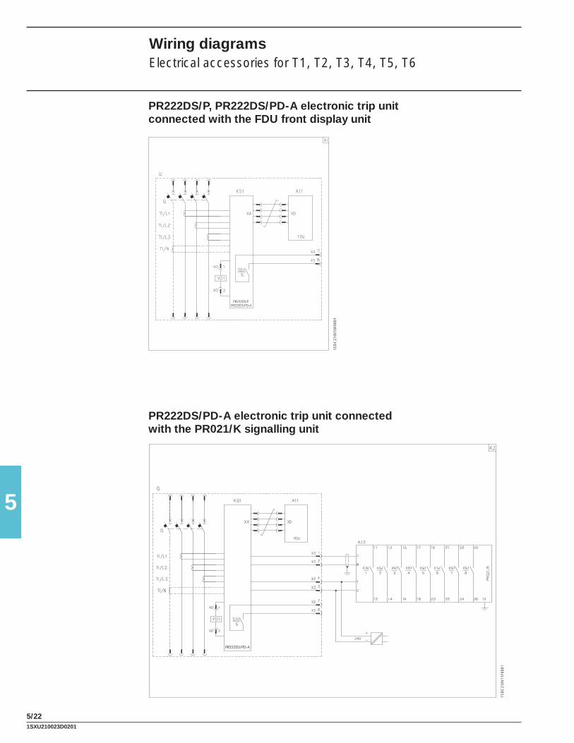
5
5/22
PR222DS/PPR222DS/PD-A
1SD
C21
0V10
F000
1
PR222DS/PD-A
1SD
C21
0V11
F000
1
PR222DS/P, PR222DS/PD-A electronic trip unit connected with the FDU front display unit
PR222DS/PD-A electronic trip unit connected with the PR021/K signalling unit
Wiring diagramsElectrical accessories for T1, T2, T3, T4, T5, T6
1SXU210023D0201

5
5/23
PR222DS/PD-A
1SD
C21
0V13
F000
1
PR222DS/PD-A
1SD
C21
0V12
F000
1
PR222DS/PD-A electronic trip unit connected with the AUX-E auxiliary contacts
PR222DS/PD-A electronic trip unit connected with the FDU front display unit and the PR021/K signalling unit
1SXU210023D0201

5
5/24
1SD
C21
0V14
F000
1
PR222DS/PD-A
1SD
C21
0V15
F000
1
45Q
PR222DS/PD-A
PR222DS/PD-A electronic trip unit connected with the AUX-E auxiliary contacts and the MOE-E actuation unit
PR222DS/PD-A electronic trip unit connected with the FDU front display unit and with the AUX-E auxiliary contacts
Wiring diagramsElectrical accessories for T1, T2, T3, T4, T5, T6
1SXU210023D0201

5
5/25
1SD
C21
0V16
F000
1
1SD
C21
0V17
F000
1
Wiring diagramsElectrical accessories for Ts3
Residual current releases, service releases and direct action motor operator
Auxiliary contacts
1SXU210023D0201

5
5/26
1SD
C21
0G29
F000
11S
DC
210G
29F0
001
Motor operating mechanism, shunt trip, closing coil and undervoltage releases
Signalling contacts
Wiring diagramsElectrical accessories for T7
1SXU210023D0201

5
5/27
1SD
C21
0G31
F000
11S
DC
210G
31F0
001
Signalling contacts
Auxiliary circuits of the PR331/P and PR332/P trip units
1SXU210023D0201

5
5/28
1SD
C21
0G32
F000
11S
DC
210G
32F0
001
PR332/P electronic trip units connected to PR330/R actuation unit and PR330/D-M dialogue unit
Measuring module PR330/V
Wiring diagramsElectrical accessories for T7
1SXU210023D0201

5
5/29
1SD
C21
0G26
F000
1
PR021/K signalling unit for PR331/P and PR332/P
1SXU210023D0201

5
5/30
TO
NE
XT
PA
GE
1SD
C21
0G21
F000
11S
DC
210G
22F0
001
ATS010 device for the automatic transfer switch of two T4-T5-T6 circuit breakers without safety auxiliary voltage supply
Wiring diagramsAutomatic transfer-switch ATS010 for T4-T5-T6
1SXU210023D0201

5
5/31
A
Q2
1
CB-E/C
1112
ATS
010
CB-E/O
14 13
15
3 24XA8
Q1
5
XA8
K2
A1
A2
K1
11
12
K2
11
12
K1
A1
A2
K2
1
2
K2
4
3
L1/Q2
N/Q2
N/Q1
L1/Q1
K1
4
3
K1
1
2
N
L
XV
XV
1XA8
XV
5XA8
XV
3
41
CB-N/O
42
40
4 2
CB-N/C
43 44
A17
M YC
S2
S1
S3 S3
S1
S2
YCM
A17
1SD
C21
0G23
F000
1
1SXU210023D0201

5
5/32
ACB-N/O
41 42
40
43
CB-N/C
44 14
CB-E/O
13
15
1112
CB-E/C
ATS
010
~
~
~
~
A17
M YC
S2
S1
S3S3
S1
S2
YCM
A17
243
XV
XA8 5
XV
XA8 1
XV
XV
Q2
1
3 24XA8
Q1
5
XA8
1SD
C21
0G24
F000
1
ATS010 device for the automatic transfer switch of two T4-T5-T6 circuit breakers with safety auxiliary voltage supply in alternating current (AC)
Wiring diagramsAutomatic transfer-switch ATS010 for T4-T5-T6
1SXU210023D0201
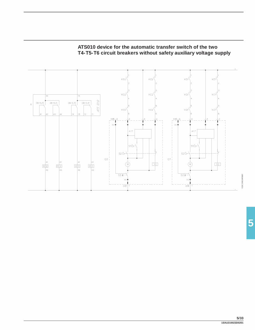
5
5/33
1SD
C21
0G34
F000
1
ATS010 device for the automatic transfer switch of the two T4-T5-T6 circuit breakers without safety auxiliary voltage supply
1SXU210023D0201

5
5/34
1SD
C21
0G37
F000
11S
DC
210G
35F0
001
EMERGENCY SUPPLY NORMAL SUPPLY
TO N
EX
T PA
GE
LOAD
Automatic transfer-switch ATS010 for the automatic transfer switch of the two T7 circuit breakers, without safety auxiliary voltage supply
Wiring diagramsAutomatic transfer-switch ATS010 for T7
1SXU210023D0201

5
5/35
1SD
C21
0G23
F000
1
FRO
M P
RE
VIO
US
PA
GE
1SXU210023D0201

5
5/36
1SD
C21
0G38
F000
1
Automatic transfer-switch ATS010 for the automatic transfer switch of the two T7 circuit breakers, with safety auxiliary voltage supply in alternating current (AC)
Wiring diagramsAutomatic transfer-switch ATS010 for T7
1SXU210023D0201

5
5/37
1SD
C21
0G39
F000
1
Automatic transfer-switch ATS010 for the automatic transfer switch of the two T7 circuit breakers, with safety auxiliary voltage supply in direct current (DC)
1SXU210023D0201

6
6/1
Overall dimensions
Index
Fixed circuit breaker and terminals
Tmax T1 and single-pole Tmax T1 ................................................................................................ 6/2
Tmax T2 ......................................................................................................................................... 6/4
Tmax T3 ......................................................................................................................................... 6/7
Tmax Ts3 ..................................................................................................................................... 6/10
Tmax T4 ....................................................................................................................................... 6/13
Tmax T5 ....................................................................................................................................... 6/16
Tmax T6 ....................................................................................................................................... 6/20
Tmax T7 ....................................................................................................................................... 6/24
Tmax T7M ................................................................................................................................... 6/29
Plug-in circuit breaker and terminals
Tmax T2 ....................................................................................................................................... 6/34
Tmax T3 ....................................................................................................................................... 6/37
Tmax Ts3 ..................................................................................................................................... 6/40
Tmax T4 ....................................................................................................................................... 6/42
Tmax T5 ....................................................................................................................................... 6/45
Draw out circuit breaker and terminals
Tmax Ts3 ..................................................................................................................................... 6/48
Tmax T4 ....................................................................................................................................... 6/50
Tmax T5 ....................................................................................................................................... 6/52
Tmax T6 ....................................................................................................................................... 6/55
Tmax T7 ....................................................................................................................................... 6/57
Tmax T7M ................................................................................................................................... 6/59
Circuit breaker with residual current release ............................................................................... 6/61
Accessories
Tmax T1 - T2 - T3 ........................................................................................................................ 6/70
Tmax Ts3 ..................................................................................................................................... 6/78
Tmax T4 - T5 ............................................................................................................................... 6/82
Tmax T6 ....................................................................................................................................... 6/89
Tmax T7 ....................................................................................................................................... 6/94
Distances to be respected .......................................................................................................... 6/99
1SXU210023D0201

6
6/2
Overall dimensionsTmax T1 and single-pole Tmax T1
Fixed circuit breaker
Fixing on sheet Fixing on DIN EN 50022 rail
Caption
1 Depth of the switchboard in the case of circuit breaker with face not extending from the compartment door, with or without flange
2 Depth of the switchboard in the case of circuit breaker with face extending from the compartment door, without flange
3 Bracket for fixing onto rail
4 Bottom terminal covers with IP40 degree of protection
5 Insulating plate
Drilling templates for support sheetFor front terminals
3 POLES 4 POLES
Without inserts With inserts
Without inserts With inserts
T1 1P (SINGLE-POLE)
1SD
C21
0400
F002
3
1SD
C21
0401
F002
3
1SD
C21
0402
F002
3
5 Nm
1.4 Nm0.8 Nm1S
DC
2104
03F0
023
1SD
C21
0404
F002
3
1SD
C21
0406
F002
3
1SD
C21
0405
F002
3
T1 1P (SINGLE-POLE)T1 1P (SINGLE-POLE)
1SD
C21
0407
F002
3
1SD
C21
0409
F002
3
1SD
C21
0408
F002
3
1SXU210023D0201

6
6/3
88.23.47
1.32
3.07
1SD
C21
0411
F002
3
1SD
C21
0412
F002
3
1SD
C21
0H18
F000
1
1SD
C21
0413
F002
3
Flange for the compartment door
Drilling templates of the compartment door
With flange andcircuit breaker face flush with door (3-4 POLES)
Without flange andcircuit breaker face flush with door (3-4 POLES)or extending (3 POLES)
Without flange andcircuit breaker face extending (4 POLES)
(SINGLE-POLE)
Terminals
1.08
0.71
1.85
1SD
C21
0Z01
F000
1
>
X X
_
843.3171
2.8
11.5
0.45
52 2.05
17 0.67
45 1.77104
4.09
25.51
1034.06
30.12
9.5x9.50.37x0.37
>_
>_ 20.08>_3
Front for copper/aluminium cables - FC CuAl
1SXU210023D0201

6
6/4
0.8
Nm
0.8 Nm
1SD
C21
0414
F002
3
1SD
C21
0415
F002
3
1SD
C21
0416
F002
3
1SD
C21
0H26
F000
1
1SD
C21
0H27
F000
1
Overall dimensionsTmax T2
Fixed circuit breaker
Flange for the compartment door
Fixing on sheet
Drilling templates of the compartment door
Drilling templates for support sheet
Fixing on DIN EN 50022 rail
With flange andcircuit breaker face flush with door (3-4 POLES)
Without flange andcircuit breaker face flush with door (3-4 POLES)
Without flange andcircuit breaker face extending (3 POLES)
For front terminals
Caption
1 Depth of the switchboard in the case of circuit breaker with face not extending from the compartment door, with or without flange
2 Depth of the switchboard in the case of circuit breaker with face extending from the compartment door, without flange
3 Bracket for fixing onto rail
4 Low terminal covers with degree of protection IP40
5 Insulating plate
Without flange andcircuit breaker face extending (4 POLES)
For rear terminals
3 POLES 4 POLES 3 POLES 4 POLES
1SD
C21
0417
F002
3
1SD
C21
0418
F002
3
1SXU210023D0201
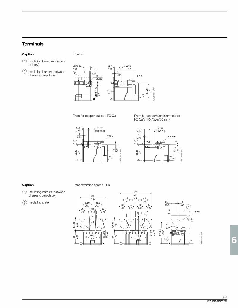
6
6/5
6 Nm2
1
1SD
C21
0421
F002
3
1
0.55x0.55
5.6 Nm
1
1SD
C21
0422
F002
3
1SD
C21
0423
F002
3
18 Nm
6 N
m
1SD
C21
0424
F002
3
Terminals
Front for copper cables - FC Cu
Front - F
Front for copper/aluminium cables - FC CuAl 1/0 AWG/50 mm2
Front extended spread - ESCaption
1 Insulating barriers between phases (compulsory)
2 Insulating plate
Caption
1 Insulating base plate (com-pulsory)
2 Insulating barriers between phases (compulsory)
1SXU210023D0201
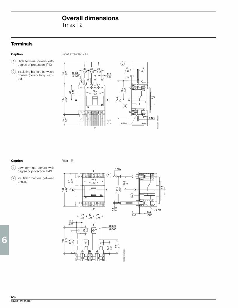
6
6/6
Front extended - EFCaption
1 High terminal covers with degree of protection IP40
2 Insulating barriers between phases (compulsory with-out 1)
Rear - RCaption
1 Low terminal covers with degree of protection IP40
2 Insulating barriers between phases
9 Nm
6 Nm
1SD
C21
0425
F002
3
9 Nm
1SD
C21
0426
F002
3
Overall dimensionsTmax T2
Terminals
1SXU210023D0201

6
6/7
Overall dimensionsTmax T3
Fixed circuit breaker
Flange for compartment door
Fixing on sheet
Drilling templates of the compartment door
Drilling templates for support sheet
Fixing on DIN EN 50022 rail
With flange andcircuit breaker face flush with door (3-4 POLES)
Without flange andcircuit breaker face flush with door (3-4 POLES)
Without flange andcircuit breaker face extending (3 POLES)
For front terminals
Caption
1 Depth o f the swi tch-board in the case of cir-cuit breaker with face not extending from the compartment door, with or without flange
2 Depth of the switchboard in the case of circuit breaker with face extending from the compartment door
3 Bracket for fixing on rail
4 Low terminal covers with degree of protection IP40
5 Insulating plate
Without flange andcircuit breaker face extending (4 POLES)
For rear terminals
1SD
C21
0440
F002
3
1SD
C21
0441
F002
3
1SD
C21
0439
F002
3
1SD
C21
0443
F002
3
1SD
C21
0442
F002
3
1SD
C21
0444
F002
3
1SD
C21
0445
F002
3
3 POLES 4 POLES 3 POLES 4 POLES
1SXU210023D0201

6
6/8
Terminals
Front for copper cables - FC CuFront - F
Front for copper/aluminium cables - FC CuAl 185 mm2
Front extended spread - ES
1SD
C21
0446
F002
3
1SD
C21
0447
F002
3
1SD
C21
0448
F002
3
X X
FC CuAl1/0 - 14 AWG
FC CuAl
300 Kcmil - 4 AWG
,
843.3179
3.11712.8
6.2
0.24
116
4.57
58 2.28 9.
30.
37
45 1.77
12.5
0.49
30.12
20.08
1034.06
1
1SD
C21
0449
F002
3
Caption
1 Insulating base plate (com-pulsory)
Caption
1 Insulating barriers between phases (compulsory)
2 Insultating plate
Overall dimensionsTmax T3
1SXU210023D0201
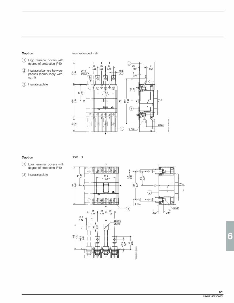
6
6/9
Front extended - EF
Rear - R
8 Nm
8 Nm
1SD
C21
0450
F002
3
9 Nm
6 Nm
1SD
C21
0451
F002
3
Caption
1 High terminal covers with degree of protection IP40
2 Insulating barriers between phases (compulsory with-out 1)
3 Insulating plate
Caption
1 Low terminal covers with degree of protection IP40
2 Insulating plate
1SXU210023D0201

6
6/10
Overall dimensionsTmax Ts3
I
O
o
off
X
Y
A
F
V
Z
C
D
E E
Y
E
= =
G
H
H
=
=
X
1
1
2 3
X1
4
(4 POLES)
(3 POLES)
B
4
I
O
o
off
I
O
o
of
1054.13
1174.61
161
6.34
1355.31
101.54
105
4.13
30.12
250.98
20.08
50.20
103.54.071074.21
10.250.40
1084.25
4.50.18
2.50.10
22.5
0.89
45 1.77
46 1.81
Mounting on sheet metal Mounting on DIN EN 50023 channel
Terminal covers (to order when not included in supply)
Low High
Fixed circuit breaker
1SD
C21
0Z04
F000
1
A B C D E F G H I L V Z
Ts3 105 140 170 87.25 35 Ø 8 143 10 73.75 18x18 24 17.54.13 5.51 6.69 3.44 1.38 Ø 0.31 5.63 0.39 2.90 0.71x0.71 0.94 0.69
Caption
1 Flange for compartment door
2 Bracket for mounting on DIN EN 50023 channel
3 1.77” (45 mm) front flange
4 Tightening torque 2 Nm
1SD
C21
0Z05
F000
1
Template for drilling sheet metal support(minimum thickness of sheet metal: 0.12”/3 mm)
For terminals:Front for flat barsExtended front Front for cables
For terminals for rear Cu/Al cables
For threaded rear terminals
Y
Y
X X
D
A
B
C
E
M5/Ø 5.5Ø 0.22
X C
Y
A
BE
X
F
G
Y
A
I
B
H
Y
Y
A
CX
L
N
M
A A
X
A A A
Y
C
L
NX
E
B
M
DD
(3 POLES)(4 POLES)
(3 POLES)(4 POLES)
(3 POLES)(4 POLES)
(3 POLES) (4 POLES)
X
Y
M5/Ø 5.5Ø 0.22
M5/Ø 5.5Ø 0.22
1SXU210023D0201

6
6/11
Template for drilling compartment door and fitting flange(thickness of sheet metal: 0.08”/2 mm)
A B C D E F G H I L M N
Ts3 35 70 139 71.75 17.5 94.75 185 R15 105 73.75 Ø 24 1431.38 2.76 5.47 2.82 0.69 3.73 7.28 R0.59 4.13 2.90 Ø 0.94 5.63
1SD
C21
0Z07
F000
1
Terminals Front for flat bars Front for cables
1SD
C21
0Z06
F000
1
Y
Y
XX
= =
= =
=
=
=
=
Ø 7Ø 0.28
1124.41
1124.41
1425.59
803.15
X
I
M8
I
L
X
10 - 0.393 - 0.12
50.20 20
0.79
1SD
C21
0Z08
F000
1
For rear Cu/Al cables
(**) high terminal covers included in supply
Extended front
(***) Separator plates between the phases to order
X
I
L(**) (***)
D
P
N
I
6
250.98
X
O
13.5 - 0.53 (S3)
I
O
o
off
Y
46 1.81
33.5
1.32
12.50.49
1SXU210023D0201
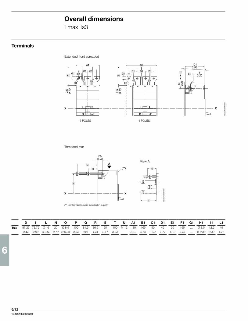
6
6/12
1SD
C21
0Z09
F000
1
1SD
C21
0Z10
F000
1
Threaded rear
View A
(**) low terminal covers included in supply
Extended front spreaded
3 POLES 4 POLES
D I L N O P Q R S T U A1 B1 C1 D1 E1 F1 G1 H1 I1 L1
Ts3 87.25 73.75 Ø 16 20 Ø 8.5 100 81.5 36.5 55 100 M 12 130 165 50 45 30 155 … Ø 8.5 12.5 45
3.44 2.90 Ø 0.63 0.79 Ø 0.33 3.94 3.21 1.44 2.17 3.94 5.12 6.50 1.97 1.77 1.18 6.10 … Ø 0.33 0.49 1.77
F1
I
O
o
off
E1D1 D1 D1
B1
G1
H1
F1
I
O
o
off
E1C1 C1
A1
G1
H1
X X
I1L1
2.5
0.10 2.5
0.10
60 2.36
1013.98
50.20
A
X
(**)
X
S
T
R
Q
I
U
250.98
Overall dimensionsTmax Ts3
Terminals
1SXU210023D0201

6
6/13
Overall dimensionsTmax T4
Fixed circuit breaker
Flange for compartment door
Drilling templates of the compartment door
Drilling templates for support sheet
For front terminals For rear terminals
3 POLES 4 POLES 3 POLES 4 POLES
Fixing on sheetCaption
1 Overall dimensions with c a b l e d a c c e s s o r i e s mounted (SOR-C, UVR-C, RC222-223)
2 Overall dimensions with cabled auxiliary contacts mounted (only 3Q 1SY)
3-4 POLES 3-4 POLES
With flange Without flange
1SD
C21
0464
F002
3
1SD
C21
0465
F002
3
1SD
C21
0466
F002
3
1SD
C21
0467
F002
3
1SD
C21
0468
F002
3
1SD
C21
0469
F002
3
1SD
C21
0470
F002
3
1SD
C21
0471
F002
3
1SD
C21
0472
F002
3
1SXU210023D0201

6
6/14
1SD
C21
0473
F002
3
1SD
C21
0474
F002
3
1SD
C21
0475
F002
3
1SD
C21
0476
F002
3
1SD
C21
0477
F002
3
1SD
C21
0478
F002
3
1SD
C21
0479
F002
3
1SD
C21
0480
F002
3
1SD
C21
0481
F002
3
1SD
C21
0482
F002
3
Terminals
Front for copper cables - FC Cu
Caption
1 Front terminals for cable connection 2x150 mm2
2 Front terminals for multica-ble connection
3 High terminal covers with degree of protection IP40
Front extended spread - ESCaption
1 Insulating barriers between phases (compulsory)
Front multicable - MC
Front for copper/aluminium cables - FC CuAl
Front - F
Overall dimensionsTmax T4
1SXU210023D0201

6
6/15
Front extended - EFCaption
1 High terminal covers with degree of protection IP40
2 Insulating barriers between phases (compulsory with-out 1)
Rear - RCaption
1 Low terminal covers with degree of protection IP40
1SD
C21
0483
F002
3
1SD
C21
0484
F002
3
1SD
C21
0485
F002
3
1SD
C21
0486
F002
3
1SD
C21
0487
F002
3
1SXU210023D0201

6
6/16
Overall dimensionsTmax T5 (400 A)
Fixed circuit breaker
Flange for compartment door
Drilling templates of the compartment door
Drilling templates for support sheet
For front terminals For rear terminals
3 POLES 4 POLES 3 POLES 4 POLES
Fixing on sheetCaption
1 Overall dimensions with ca-bled accessories mounted (SOR-C, UVR-C, RC222)
2 Overall dimensions with cabled auxiliary contacts mounted (only 3Q 1SY)
With flange (3-4 POLES) Without flange (3-4 POLES)
1SD
C21
0528
F002
3
1SD
C21
0529
F002
3
1SD
C21
0530
F002
3
1SD
C21
0531
F002
3
1SD
C21
0532
F002
3
1SD
C21
0533
F002
3
1SD
C21
0534
F002
3
1SD
C21
0536
F002
3
1SD
C21
0535
F002
3
1SXU210023D0201

6
6/17
1SD
C21
0Z13
F002
3
1SD
C21
0Z14
F002
3
1SD
C21
0Z15
F002
3
Caption
1 High terminal covers with degree of protection IP40
Front for copper/aluminium cables Cu/Al 300 mm2 FC CuAl
Front for copper/aluminium cables Cu/Al 2x240 mm2 - FC CuAl
Terminals
Front - F
Front for copper cables - FC Cu
1SD
C21
0537
F002
3
1SD
C21
0538
F002
3
1SD
C21
0539
F002
3
1SXU210023D0201

6
6/18
Front extended - EFCaption
1 High terminal covers with degree of protection IP40
2 Insulating barriers between phases (compulsory with-out 1)
Caption
1 Low terminal covers with degree of protection IP40
Terminals
Front extended spread - ESCaption
1 Insulating barriers between phases (compulsory)
Rear - R
1SD
C21
0543
F002
3
1SD
C21
0544
F002
3
1SD
C21
0545
F002
3
1SD
C21
0546
F002
3
1SD
C21
0547
F002
3
1SD
C21
0548
F002
3
1SD
C21
0549
F002
3
Overall dimensionsTmax T5 (400 A)
1SD
C21
0550
F002
3
1SXU210023D0201

6
6/19
Fixed circuit breaker
Fixing on sheetCaption
1 Front terminals for 2x240 mm2 cable connection
2 Compartment door sheet steel drilling
3 Flange for the compartment door
4 Fixing on sheet steel
5 Tightening torque 2 Nm
6 Tightening torque 31 Nm
7 Terminal cover
8 Insultating barrier + insula-ting plate
9 Terminals support
10 Spacing when equipped w i th SOR-C, UVR-C, RC221-222
11 Spacing when equipped with AUX-C (3Q 1SY only)
1SD
C21
0771
F002
31S
DC
2107
71F0
023
1SD
C21
0771
F002
3
With flange Without flange
A 115 107
4.53 4.21
B 115 107
4.53 4.21
C 64.5 60.5
2.54 2.38
Overall dimensionsTmax T5 (600 A)
1SXU210023D0201

6
6/20
105
210 (3P)
280 (4P)
5.52.7
707070
2.7134
268
140= =
2.76 2.76 2.76
4.13
8.27
0.11
0.11
0.22
11.02
5.51
10.5
5
5.28
1SD
C21
020A
F000
1
105
61.2
5
1074.21
3
1596.26
103.54.07
1154.53
20.12 0.08
4.13
2.41
1SD
C21
021A
F000
1
152= =
77.7
5
138
3.06 5.98
5.43
149= =
66.7
5
116
5.87
2.63
4.57
1SD
C21
022A
F000
1
142= =
62.2
5
107
5.59
2.45
4.21
1SD
C21
023A
F000
1
1SD
C21
024A
F000
1
237
5.5 - M5
118.
5
702.76
Ø 0.22
4.67
9.33
140
237
5.5 - M5 35
118.
5
9.33
4.67
Ø 0.22
5.51
1.38
1SD
C21
025A
F000
1
1SD
C21
026A
F000
1
Overall dimensionsTmax T6
Fixed circuit breaker
Fixing on sheetCaption
1 Overall dimensions with ca-bled accessories mounted (SOR-C, UVR-C)
2 Overall dimensions with cabled auxiliary contacts mounted (only 3Q 1SY)
Drilling templates of the compartment door
With flange 3-4 POLES Without flange 3-4 POLES
Flange for the compartment door
Drilling templates for support sheetFor front terminals F, EF, ES, FC Cu, FC CuAl
3 POLES 4 POLES
1SXU210023D0201

6
6/21
705.5 - M5
118.
5
150.
5
237
301
171.521.5R
2.76Ø 0.22
6.75R 0.85
9.33
11.8
5 4.66 5.
92
35
140
241.5
5.5 - M5
118.
5
150.
5
237301
21.5R85.75
5.51
1.38Ø 0.22
11.8
5
9.33
4.66 5.92
9.51
3.38
1SD
C21
027A
F000
1
1SD
C21
028A
F000
1
70
35Ø 5.5 M5
Ø 35
70 70
120.
5
241
237
118.
5
8
X X
Y
Y
2.76
1.38Ø 0.22
2.762.76
9.49
4.74
4.66
9.33
0.31
Ø 1.38
Ø 5.5 M5
140
35
70 70 70Ø 35
237
118.
5
XX
Y
Y
8
241
120.
5
2.76
1.38Ø 0.22
2.762.76
9.49
4.74
4.66
9.33
2.76
0.31
Ø 1.381SD
C21
029A
F000
1
1SD
C21
030A
F000
1
Drilling templates for support sheet
For rear terminals for Cu/Al cables
3 POLES 4 POLES
For rear terminals - R
1SXU210023D0201

6
6/22
MA
X 1
2
40MAX
18 M
IN
22.5 ±0.16.5
Ø 0.260.89
120.
5
23 MIN5 MAX100.9
4.74
1SD
C21
031A
F000
1
1SD
C21
032A
F000
1
20707070
134
39
2.76 2.76 2.760.79
1.53
5.28
19
120.
5
25.559
4.74
2.321
Ø 0.75
1SD
C21
033A
F000
1
1SD
C21
034A
F000
1
134
53.5
707070
5014
2.76 2.76 2.76
1.970.55
2.11
5.28 16
7.5
833.51.32 0.31
6.59
1SD
C21
035A
F000
1
1SD
C21
036A
F000
1
134
116.
5
45
90
13
4511611611645
23
88 9088
1.77 4.57 4.57 4.57 1.77
3.54 3.543.46 3.46
Ø 0.511.77 0.9
4.59
5.28
88
13
116116 4545
134
116.
5
45 23
90881.77 4.57 4.57 1.77
3.543.46 3.46
Ø 0.510.9
4.59
5.28
1.77
1SD
C21
037A
F000
1
1SD
C21
038A
F000
1
Caption
1 Insulating barriers between phases (compulsory)
1SD
C21
039A
F000
1
230.
5
50 81.97 0.31
9.07
1
Terminals Front - F
Front for copper/aluminium cables Cu/Al 3x185 mm2 FC CuAl
Front extended - EF
Front extended spread - ES
4 POLES 3 POLES
Overall dimensionsTmax T6
1SXU210023D0201

6
6/23
73
33
707070
53
14
2.09
2.76 2.76 2.76
1.3
2.87
Ø 0.55
280 (4P)
210 (3P)8.27 (3P)
11.02 (4P)
53
812
0.5
2.09
4.74
0.31
53
14
120.
5
33
2.09
4.74
1.3
Ø 0
.55
8707070
73 2.87
2.762.762.760.31
1SD
C21
042A
F000
1
1SD
C21
043A
F000
1
1SD
C21
044A
F000
1
1SD
C21
045A
F000
1
1SD
C21
046A
F000
1
1
Rear - R
Caption
1 Low terminal covers with degree of protection IP40
3-4 POLES
3-4 POLES
707070
41
134
39.5 2.76 2.76 2.76
1.611.55
5.28
1SD
C21
040A
F000
1
1SD
C21
041A
F000
1
120.
5
23.1
48.1
17.5
147
137.
5
0.91
1.89
Ø 0
.69
4.745.
415.79
Rear for copper cables Cu/Al - RC CuAl
1SXU210023D0201

6
6/24
210125
97
1010
10
24
14.5
105
204
102
18.7
5
2252
30.12
8.860.08
0.94
0.39
0.390.39
3.82
4.92
0.58
0.74
4.02
8.03
4.13
1SD
C21
047A
F000
11S
DC
2104
9AF0
001
35.2
51.
39
1927.56
2037.99
2017.91
138
5.43
116
4.57
24.2
50.
95 107
4.21
19.7
50.
78
206
8.11
103
4.0515
15.
94
263
10.3
5
144.
55.
6914
4.5
5.69
2088.19
2419.492268.9
1556.1
20.08 Ø 4 n°7 HOLES
Ø 0.16
35.2
51.
39
1927.56
2037.99
2017.91
138
5.43
116
4.57
24.2
50.
95 107
4.21
19.7
50.
78
206
8.11
103
4.0515
15.
94
263
10.3
5
144.
55.
6914
4.5
5.69
2088.19
2419.492268.9
1556.1
20.08 Ø 4 n°7 HOLES
Ø 0.16
35.2
51.
39
1927.56
2037.99
2017.91
138
5.43
116
4.57
24.2
50.
95 107
4.21
19.7
50.
78
206
8.11
103
4.0515
15.
94
263
10.3
5
144.
55.
6914
4.5
5.69
2088.19
2419.492268.9
1556.1
20.08 Ø 4 n°7 HOLES
Ø 0.16
50
2570 70 70
103.6
6
134
147.
5
210
280
268
0.98
1.97
2.762.76 2.76
4.08
0.24
5.81
5.28
8.27
11.02
10.5
5
4.92
125
5.98
152
6.07
154.
25
6.3
160
1907.48
2068.11
26810.55
152
5.98
304
11.9
7
351.38
Ø 5.5 - M5Ø 0.22
245
9.65
122.
54.
82
50
2570 70 70
103.6
6
134
147.
5
210
280
268
0.98
1.97
2.762.76 2.76
4.08
0.24
5.81
5.28
8.27
11.02
10.5
5
4.92
125
5.98
152
6.07
154.
25
6.3
160
1907.48
2068.11
26810.55
152
5.98
304
11.9
7
351.38
Ø 5.5 - M5Ø 0.22
245
9.65
122.
54.
82
50
2570 70 70
103.6
6
134
147.
5
210
280
268
0.98
1.97
2.762.76 2.76
4.08
0.24
5.81
5.28
8.27
11.02
10.5
5
4.92
125
5.98
152
6.07
154.
25
6.3
160
1907.48
2068.11
26810.55
152
5.98
304
11.9
7
351.38
Ø 5.5 - M5Ø 0.22
245
9.65
122.
54.
82
1SD
C21
048A
F000
1
1SD
C21
048A
F000
1
1SD
C21
049A
F000
1
1SD
C21
049A
F000
1
Overall dimensionsTmax T7
Fixed circuit breaker Front terminal – F
Drilling templates for support sheet
Caption
1 Front terminals for flat con-nection
2 Busbars
3 Flange for the compartment door
4 Flange fixing screws
6 Drilling template for fixing onto support sheet
7 Tightening torque: 18 Nm
8 Key lock (optional)
9 Padlock (optional)
10 Tightening torque: 2.5 Nm
11 Sheet drilling for compart-ment door with flange
12 Sheet dri l l ing for com-partment door for front 206 x 204
13 Terminal for auxiliary con-tacts
14 Reduce flange for the com-partment door (optional)
15 Sheet drilling for compart-ment door with reduced flange
16 Sheet dri l l ing for com-partment door for front 190 x 105
Flange for the compartment door (supplied as standard)
Drilling templates of the compartment door
With flange Without flange
A 125...141 147
4.92...5.55 5.79
III IV
C 70 140
2.76 5.51
1SD
C21
048A
F000
1
1SXU210023D0201

6
6/25
592.32
18.50.73
46.51.8459
2.32
702.76
702.76
702.76
441.73
250.98
118.
54.
66
237
9.3427
310
.75
150.
59
46.5
1.84
Ø 11
Ø 0.43
44 1.73
109
4.29
218
8.58
25 0.98
Ø 11
Ø 0.4
3
702.76
702.76
702.76
150.59
61.252.41
351.38
17.50.69
Ø 5.5 - M5Ø 0.22
245
9.65 52
.52.
07
39.7
51.
56
122.
54.
82
80.
31
1SD
C21
051A
F000
1
702.76
702.76
702.76
150.59
61.252.41
351.38
17.50.69
Ø 5.5 - M5Ø 0.22
245
9.65 52
.52.
07
39.7
51.
56
122.
54.
82
80.
31
1SD
C21
051A
F000
1
Terminals
Rear terminals HR or VR
Drilling templates for support sheet
Caption
1 Rear horizontal terminals
2 Rear vertical terminals
6 Support sheet dr i l l ing template
7 Tightening torque: 20 Nm
III IV
B 70 140
2.76 5.51
C 192.5 262.5
7.58 10.33
1SD
C21
050A
F000
1
1SXU210023D0201
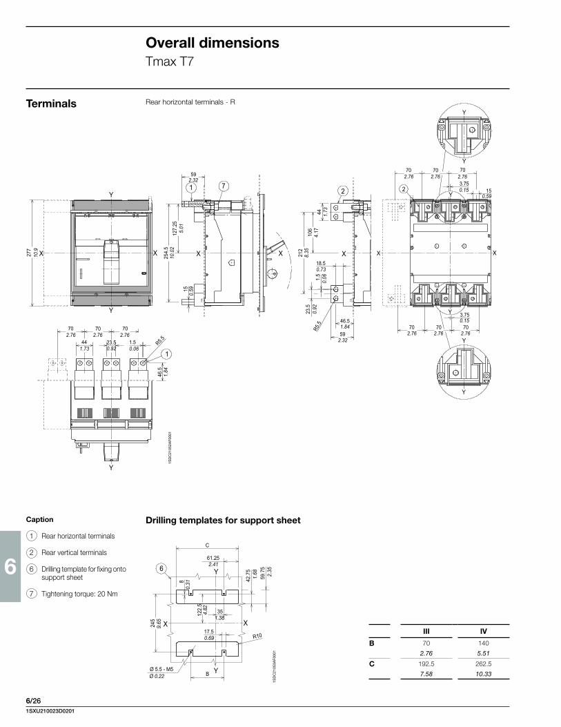
6
6/26
70 70 70
3.7515
3.75
70 70 70
Y
Y
Y
Y
Y
Y
XXXX18.5
46.5
59
212
106
441.
5R
5.5
22
23.5
7115
127.
25
254.
5
59
XXX
Y
Y
277
70 70 70
44 23.5 1.5 R5.546
.5
Y
1
2.325.
01
10.0
2
0.59
10.9
4.17
1.73
8.35
0.73
0.06
0.92
1.84
2.32
0.15
2.76 2.76 2.76
0.15
2.76 2.76 2.76
0.59
2.76 2.76 2.76
1.73 0.92 0.06
1.84
1SD
C21
052A
F000
1
61.25
C
35
17.5
Ø 5.5 - M5B
X X
Y
Y
122.
5
245
42.7
5
59.7
5
R10
6
8
2.41
1.38
0.69
Ø 0.22
9.65
4.82
0.31
1.68 2.35
Overall dimensionsTmax T7
Terminals Rear horizontal terminals - R
Caption
1 Rear horizontal terminals
2 Rear vertical terminals
6 Drilling template for fixing onto support sheet
7 Tightening torque: 20 Nm
Drilling templates for support sheet
III IV
B 70 140
2.76 5.51
C 192.5 262.5
7.58 10.33
1SD
C21
053A
F000
1
1SXU210023D0201

6
6/27
320
250
125
70 70 70
25 44 Ø 11Y
XX X X
100
29.5
15 8
1
7
9
250
118.
5
229
199.
5
160.
5
7912
.5
25
1
12.6
9.84
4.92
2.76 2.76 2.76
0.98 1.73 Ø 0.43
6.32
7.85 9.
02 9.84
4.66
0.59
29.5
3.94
0.49
0.98
3.11
50
2570 70 70
103.6
6
134
147.
5
210
280
268
0.98
1.97
2.762.76 2.76
4.08
0.24
5.81
5.28
8.27
11.02
10.5
5
4.92
125
5.98
152
6.07
154.
25
6.3
160
1907.48
2068.11
26810.55
152
5.98
304
11.9
7
351.38
Ø 5.5 - M5Ø 0.22
245
9.65
122.
54.
82
1SD
C21
048A
F000
1
1SD
C21
054A
F000
11S
DC
2105
5AF0
001
116 / 4.57 116 / 4.57 116 / 4.57
90 / 3.54 90 / 3.54 90 / 3.54
23
45 45 23 451.77 1.77 0.91 1.77
33
79
147
.5
144
334
118.
5
X X
100
40.5
15 7
2
10Ø 1
3Ø
0.5
1
~200
100
1.3
3.11
3.94
1003.94
552.17
268
134
~10.
16
10.5
5
5.28
793.11
451.77
258
189
5.8
1
5.67
10.1
6
7.44
9
Extended front terminals - EFCaption
1 Extended front terminals EF
2 Extended front spread termi-nals ES
6 Drilling template for fixing onto support sheet
7 Tightening torque: 18 Nm
8 Phase separator 100 mm
9 Protection plate
10 Phase separator 200 mm
13 Clamp for auxiliary contacts
Drilling templates for support sheet
Rear spread terminals - ES
III IV
C 70 140
2.76 5.51
1SXU210023D0201

6
6/28
320
250
125
70 70 70
28Y
YX X
8
150
79
202
34.7566.25
101
1
2
7
1
Ø 21.5Y
X X
2.76 2.76 2.76
1.1
4.92
9.84
12.6
5.9
3.11
3.98
2.610.52
0.04
7.95
Ø 0.85
1SD
C21
056A
F000
1
Overall dimensionsTmax T7
Front FC CuAl cable terminal - 4x240 mm2
Terminals
Caption
1 Front terminals for cables FC CuAl
2 Tightening torque: 43 Nm
7 Tightening torque: 18 Nm
8 Protection plate
1SXU210023D0201

6
6/29
With flange Without flange
A 125...184 170
4.92...7.24 6.7
III IV
C 70 140
2.76 5.51
Standard Ronis Profalux Kirk Castell
B 208 216 224 no no
8.19 8.5 8.82 no no
1SD
C21
059A
F000
1
1SD
C21
058A
F000
1
1SD
C21
057A
F000
1
501.97
250.9870
2.7670
2.7670
2.76
103.64.08
60.24
134
5.28 14
7.5
5.81
2108.27280
11.02
268
10.5
517
87.
01
1907.48
2068.11
26810.55
125
4.92
175
6.89
304
11.9
715
25.
9824
59.
6512
2.5
4.82 35
1.38
Ø 5.5 - M5Ø 0.22
501.97
250.9870
2.7670
2.7670
2.76
103.64.08
60.24
134
5.28 14
7.5
5.81
2108.27280
11.02
268
10.5
517
87.
01
1907.48
2068.11
26810.55
125
4.92
175
6.89
304
11.9
715
25.
9824
59.
6512
2.5
4.82 35
1.38
Ø 5.5 - M5Ø 0.22
1SD
C21
058A
F000
1
1SD
C21
058A
F000
1
Fixed circuit breaker Front terminal
Caption
1 Front terminal for flat con-nection
2 Busbars
3 Flange for the compartment door
4 Flange fixing screws
6 Drilling template for fixing onto support sheet
7 Tightening torque: 18 Nm
8 Key lock (optional)
9 Padlock (optional)
10 Tightening torque: 2.5 Nm
11 Compartment door with flange sheet drilling
12 Compartment door without flange sheet drilling
13 Terminal for auxiliary con-tacts
Flange for the compartment door (supplied as standard)
Drilling templates for support sheet
Drilling templates of the compartment door
Overall dimensionsTmax T7M
501.97
250.9870
2.7670
2.7670
2.76
103.64.08
60.24
134
5.28 14
7.5
5.81
2108.27280
11.02
268
10.5
517
87.
01
1907.48
2068.11
26810.55
125
4.92
175
6.89
304
11.9
715
25.
9824
59.
6512
2.5
4.82 35
1.38
Ø 5.5 - M5Ø 0.22
1254.92
973.82
100.39 10
0.3910
0.3924
0.94
118.
54.
66
237
9.34
14.5
0.58
102
4.02
204
8.03
193.57.62
≥ 3≥ 0.12 2
0.079
2419.492268.9
2088.19
144.
55.
6914
4.5
5.69
151
5.94
263
10.3
5 103
4.05
206
8.11
Ø 4 n°7 HOLESØ 0.16
1SXU210023D0201

6
6/30
109
4.29
25 0.98
27
X XXXX
Y
Y 1
X
Y
1
2Y
Ø 11
592.32
118.
54.
66
237
9.34
150.
59
44 1.73
218
8.58
18.50.73
46.51.8459
2.32
Ø 11Ø 0.43
702.76
702.76
702.76
441.73
250.98
702.76
702.76
702.76 15
0.59
46.5
1.84
Ø 0.43
273
10.7
5
1SD
C21
060A
F000
1
1SD
C21
061A
F000
1
61.25
17.5
Ø 5.5 - M5 Y
Y
X X
C
B
122.
5
245 52
.5
39.7
5
8
6
R 10
2.41
0.69
Ø 0.22
9.65 2.
07
1.56
0.31
4.82
Overall dimensionsTmax T7M
Drilling templates for support sheetCaption
1 Rear horizontal terminals
2 Rear vertical terminals
6 Drilling template for fixing onto support sheet
7 Tightening torque 20 Nm
Rear terminals - HR/VR
III IV
B 70 140
2.76 5.51
C 192.5 262.5
7.58 10.33
Fixed circuit breaker
1SXU210023D0201
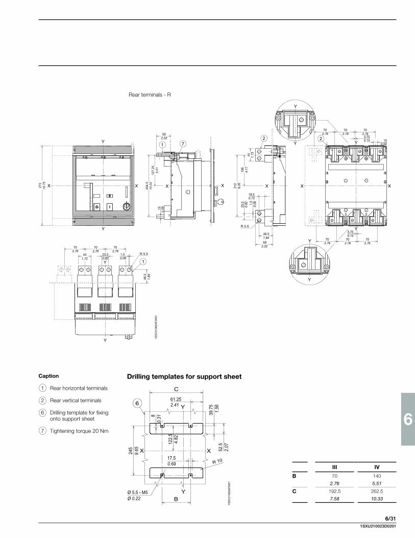
6
6/31
1SD
C21
063A
F000
1
Caption
1 Rear horizontal terminals
2 Rear vertical terminals
6 Drilling template for fixing onto support sheet
7 Tightening torque 20 Nm
Drilling templates for support sheet
Rear terminals - R
254.
5
127.
25
15
273
Y
Y
XX X X X
1 72
X
2
R 5.5
X
Y
Y
Y
Y
Y
Y
R 5.5
Y
Y
1
592.32
44 1.73
18.50.73
592.3270
2.7670
2.7670
2.76
150.59
46.5
1.84
10.7
5
5.01
10.0
2
0.59
441.73
23.50.92
1.50.06
46.51.84
23.5
0.92 1.
50.
06
212
8.35
106
4.17
702.76
702.76
702.76
3.750.15
702.76
702.76
702.763.750.15 15
0.59
1SD
C21
062A
F000
1
C
B
Y
Y
X X
6
R 10
61.25
17.5
Ø 5.5 - M5
122.
5
245 52
.5
39.7
5
8
2.41
0.69
Ø 0.22
9.65 2.
07
1.56
0.31
4.82
III IV
B 70 140
2.76 5.51
C 192.5 262.5
7.58 10.33
1SXU210023D0201
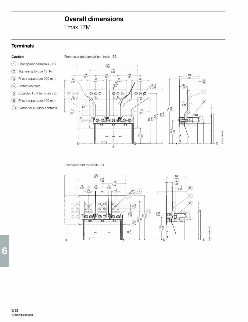
6
6/32
1SD
C21
064A
F000
1
1SD
C21
065A
F000
1
Extended front terminals - EF
Front extended spread terminals - ESCaption
1 Rear spread terminals - ES
2 Tightening torque 18 Nm
3 Phase separators 200 mm
4 Protection plate
5 Extended front terminals - EF
6 Phase separators 100 mm
13 Clamp for auxiliary contacts
Overall dimensionsTmax T7M
Ø 13Ø 0.51
230.9
903.54
903.54
903.54
903.54
1164.57
1164.57
1164.57
2509.84
32012.6
451.77
451.77
331.3
793.11
793.11
79 3.11
229
9.02 25
810
.16 27
810
.94
334
13.1
511
8.5
4.66
40.51.59
150.59
1003.94
451.77
451.77
6
5
13
32012.6
2509.84 125
4.92702.76
702.76
702.76
250.98
441.73
Ø 11Ø 0.43
79 3.11
25 0.98
12.5
0.49
160.
56.
32 199.
57.
8522
99.
02 250
9.84
118.
54.
66
1003.9429.51.16
150.59
Terminals
1SXU210023D0201

6
6/33
32012.6
2509.84
1254.92
702.76
702.76
702.76
79 3.11
150
5.9
281.1
1013.98
66.252.6134.75
1.3710.04
202
7.95
Ø 21.5Ø 0.85
1SD
C21
066A
F000
1
Caption
1 Front terminals for cable FC CuAl
2 Tightening torque 43 Nm
7 Tightening torque 18 Nm
8 Protection plate
Front terminals for cable FC CuAl - 4x240 mm2
1SXU210023D0201

6
6/34
Overall dimensionsTmax T2
Plug-in circuit breaker
Flange for compartment door
Fixing on sheet
Drilling templates of the compartment door
Drilling templates for support sheet
With flange andcircuit breaker face flush with door (3-4 POLES)
Without flange andcircuit breaker face flush with door (3-4 POLES)
Without flange andcircuit breaker face extending (3 POLES)
For front terminals
Caption
1 Depth of the switchboard in the case of circuit breaker with face not extending from the compartment door, with or without flange
2 Depth of the switchboard in the case of circuit breaker with face extending from the compartment door, without flange
3 Cradle
4 Moving part with terminal covers, degree of protec-tion IP40
Without flange andcircuit breaker face extending (4 POLES)
For rear terminals
3 POLES 4 POLES3 POLES 4 POLES
1SD
C21
0427
F002
3
1SD
C21
0428
F002
3
1SD
C21
0429
F002
3
1SD
C21
0430
F002
3
1SD
C21
0431
F002
3
1SD
C21
0432
F002
3
1SXU210023D0201

6
6/35
Terminals
Front for copper cables - FC Cu
Front - F
Front extended spread - ESCaption
1 Insulating barriers between phases (compulsory)
Front for copper/aluminium cables - FC CuAl 1/0 AWG/50 mm2
6 Nm
1SD
C21
0433
F002
3
5.6 Nm
1SD
C21
0434
F002
3
1SD
C21
0435
F002
3
57.2
5
6 N
m 18 Nm
1SD
C21
0436
F002
3
1SXU210023D0201

6
6/36
Front extended - EFCaption
1 High terminal covers with degree of protection IP40
2 Insulating barriers between phases (compulsory with-out 1)
Rear - RCaption
1 Low terminal covers with degree of protection IP40
Overall dimensionsTmax T2
6 N
m
9 Nm
1SD
C21
0437
F002
3
Terminals
9 N
m1S
DC
2104
38F0
023
1SXU210023D0201

6
6/37
Overall dimensionsTmax T3
Plug-in circuit breaker
Flange for compartment door
Fixing on sheet
Drilling templates of the compartment door
Drilling templates for support sheet
With flange andcircuit breaker face flush with door (3-4 POLES)
Without flange andcircuit breaker face flush with door (3-4 POLES)
Without flange andcircuit breaker face extending (3 POLES)
For front terminals
Without flange andcircuit breaker face extending (4 POLES)
For rear terminals
3 POLES 4 POLES
3 POLES 4 POLES
Caption
1 Depth of the switchboard in the case of circuit breaker with face not extending from the compartment door, with or without flange
2 Depth of the switchboard in the case of circuit breaker with face extending from the compartment door, wi-thout flange
3 Fixed part
4 Moving part with terminal covers, degree of protection IP40
1SD
C21
0452
F002
3
1SD
C21
0453
F002
3
1SD
C21
0454
F002
3
1SD
C21
0455
F002
31S
DC
2104
57F0
0231S
DC
2104
56F0
023
1SXU210023D0201

6
6/38
Terminals
Front for copper cables - FC CuFront - F
Front extended spread - ESCaption
1 Insulating barriers between phases (compulsory)
Front for copper/aluminium cables - FC CuAl 1/0 AWG/50 mm2
Overall dimensionsTmax T3
8 Nm
1SD
C21
0458
F002
3
1SD
C21
0459
F002
3
100.39
1SD
C21
0460
F002
3
8 N
m
18 Nm
1SD
C21
0461
F002
3
1SXU210023D0201

6
6/39
8 N
m
18 Nm
1SD
C21
0462
F002
3
6 Nm9 Nm
1SD
C21
0463
F002
3
Front extended - EFCaption
1 High terminal covers with degree of protection IP40
2 Insulating barriers between phases (compulsory with-out 1)
Rear - RCaption
1 Low terminal covers with degree of protection IP40
1SXU210023D0201

6
6/40
Overall dimensionsTmax Ts3
1SD
C21
0Z51
F000
1
Plug-in circuit breaker
Caption
1 Cradle
2 Moving part complete with IP20 protection class termi-nal covers
3 Flange for compartment door
4 Lock for compartment door (to order)
5 Tightening torque 1.1 Nm
Template for drilling sheet metal support(minimum thickness of sheet metal: 0.12”/3 mm)
For terminals: Front for flat barsFront for cables
For terminals:Threaded rear
30.12
Y
Y
X
= =
=
=
=
=
X
(4 POLES)
(3 POLES)
5
1
I
O
o
off
B
D
E EE
F
C
3 2
3
A
5
G
T
1174.61
1536.02156.56.16184.57.26
20.08
105
4.1316
16.
34
1054.13
Y
Y
X
D
AB
C
E
F
Y
Y
X
D
I
E
G
HC
F
AB
L
M
N
(3 POLES)
(4 POLES)
(3 POLES)
(4 POLES)
(3 POLES)
(4 POLES)
A B C D E F G H
Ts3 105 140 175 89.75 35 52.5 143 844.13 5.51 6.89 3.53 1.38 2.07 5.63 3.31
A B C D E F G H I L M N
Ts3 70 105 100 52.25 25 M4-Ø5 73.75 143 35 70 105 R142.76 4.13 3.94 2.06 0.98 M4-Ø0.20 2.90 5.63 1.38 2.76 4.13 R0.55
1SD
C21
0Z52
F000
1
1SD
C21
0Z53
F000
1
Template for drilling compartment door and fitting flange(thickness of sheet metal: 0.08”/2 mm)
Y
Y
XX
= =
= =
=
=
=
=
Ø 7Ø 0.28
1124.4180
3.15
112
4.41
142
5.59
1SXU210023D0201

6
6/41
1SD
C21
0Z54
F000
1
Terminals
Front for flat bars (up to 400 A) Threaded rearFront for cables (up to 400 A)
View A
AQ
R
S
P
N
I
L
M
31 1.22 (S3-S4)34 1.34 (S5)
V
U
Z
83 3.27 (S3-S4)84 3.31 (S5)
L
L
311.22
17.50.69
I L M N O P Q R S T U V Z
Ts3 10 33.5 Ø8.5 20 5 37.5 79.5 36 18x18 73.75 48 M12 1000.39 1.32 Ø0.33 0.79 0.20 1.48 3.13 1.42 0.71x0.71 2.90 1.89 3.94
1SXU210023D0201

6
6/42
Plug-in circuit breaker
Flange for compartment door
Fixing on sheet
Drilling templates of the compartment door
Caption
1 Fixed part
2 Moving part with terminal covers, degree of protec-tion IP40
3 Overall dimensions with cabled accessories moun-ted (SOR-C, UVR-C, RC221-222)
4 Overall dimensions with cabled auxiliary contacts mounted (only 3Q 1SY)
With flange Without flange
Drilling templates for support sheet
For front terminals For rear terminals
3 POLES 4 POLES
3 POLES 4 POLES
Overall dimensionsTmax T4
1SD
C21
0488
F002
3
1SD
C21
0489
F002
3
1SD
C21
0490
F002
3
1SD
C21
0491
F002
3
1SD
C21
0492
F002
3
1SD
C21
0493
F002
3
1SD
C21
0494
F002
3
1SD
C21
0495
F002
3
1SD
C21
0496
F002
3
1SXU210023D0201

6
6/43
Terminals
Front for copper cables - FC Cu or for copper/aluminium cables - FC CuAlCaption
1 For Cu cables
2 For Cu Al cables
3 High terminal covers with degree of protection IP40
Front - EF
1SD
C21
0Z56
F000
1
1SD
C21
0Z55
F000
1
1SD
C21
0497
F002
3
1SD
C21
0498
F002
3
1SXU210023D0201

6
6/44
Rear flat horizontal - HR
Rear flat vertical - VR
3-4 POLES
3-4 POLES
Overall dimensionsTmax T4
1SD
C21
0501
F002
3
1SD
C21
0502
F002
3
1SD
C21
0503
F002
3
1SD
C21
0504
F002
3
1SD
C21
0505
F002
3
1SD
C21
0506
F002
3
Terminals
1SXU210023D0201

6
6/45
Plug-in circuit breaker
Fixing on sheetCaption
1 Fixed part
2 Moving part with terminal covers, degree of protec-tion IP40
3 Overall dimensions with ca-bled accessories mounted (SOR-C, UVR-C, RC221-222)
4 Overall dimensions with cabled auxiliary contacts mounted (only 3Q 1SY)
Overall dimensionsTmax T5 (400 A)
Flange for compartment door
Drilling templates of the compartment door
With flange Without flange
Drilling templates for support sheet
For front terminals
3 POLES 4 POLES
For rear terminals
3 POLES 4 POLESA B C D E
Rear 400 A 32.5 128.5 143 172.5 64.5
1.28 5.06 5.63 6.79 2.54
1SD
C21
0551
F002
3
1SD
C21
0552
F002
3
1SD
C21
0555
F002
3
1SD
C21
0556
F002
3
1SD
C21
0557
F002
3
1SD
C21
0558
F002
3
1SD
C21
0559
F002
3
1SD
C21
0560
F002
3
1SD
C21
0561
F002
3
1SXU210023D0201
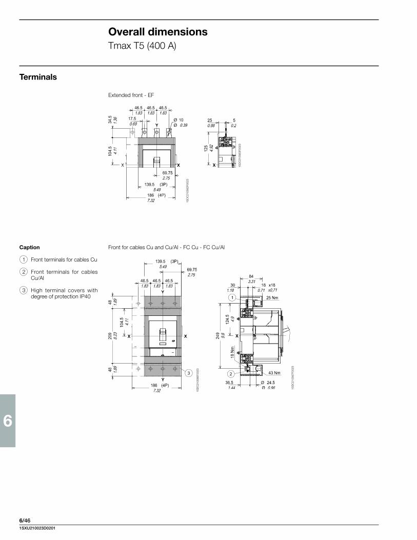
6
6/46
1SD
C21
0562
F002
3
1SD
C21
0563
F002
3
1SD
C21
0566
F002
3
1SD
C21
0567
F002
3
Terminals
Front for cables Cu and Cu/Al - FC Cu - FC Cu/AlCaption
1 Front terminals for cables Cu
2 Front terminals for cables Cu/Al
3 High terminal covers with degree of protection IP40
Extended front - EF
Overall dimensionsTmax T5 (400 A)
1SXU210023D0201

6
6/47
1SD
C21
0573
F002
3
1SD
C21
0571
F002
3
1SD
C21
0572
F002
3
1SD
C21
0576
F002
3
1SD
C21
0574
F002
3
1SD
C21
0575
F002
3
Rear flat horizontal - HR
Rear vertical - VR
1SXU210023D0201

6
6/48
1SD
C21
0257
F000
3
1SD
C21
0259
F000
3
Note: The draw out circuit breaker must be completed with one of the following acces-sories: – front flange for operating
lever mechanism – rotary handle operating
mechanism – motor operator
Caption
1 Cradle
2 Moving part complete with IP20 protection class termi-nal covers
3 Flange for compartment door
4 Lock for compartment door (to order)
5 Tightening torque 1.1 Nm
Template for drilling sheet metal support(minimum thickness of sheet metal: 0.12”/3 mm)
For terminals: Front for flat barsFront for cables
For terminals:Threaded rear
isolating travel3
0.12(4 POLES)
(3 POLES)
X
= =
Y
Y
Ø 5.5Ø 0.22
1
5
5
B
A
E E EF
H
D
=
=
X
24 3
CG
T
1676.57
1054.13
742.91
963.78
27.51.08
1.750.07
195.57.70
1907.48
20.08
105
4.13
161
6.34
Y
Y
X
D
AB
C
E
F
Y
Y
X
D
I
E
G
HC
F
AB
L
M
N
(3 POLES)
(4 POLES)
(3 POLES)
(4 POLES)
(3 POLES)
(4 POLES)
Overall dimensionsTmax Ts3
Draw out circuit breaker
A B C D E F G H
Ts3 105 140 175 89.75 35 52.5 143 844.13 5.51 6.89 3.53 1.38 2.07 5.63 3.31
A B C D E F G H I L M N
Ts3 70 105 100 52.25 25 M4-Ø5 73.75 143 35 70 105 R142.76 4.13 3.94 2.06 0.98 M4-Ø0.20 2.90 5.63 1.38 2.76 4.13 R0.55
1SD
C21
0Z60
F000
1
Template for drilling compartment door and fitting flange(thickness of sheet metal: 0.08”/2 mm)
Ø 7Ø 0.28
X
Ø 4Ø 0.16
Y
Y
X
=
=
Nr. 3 Ø 8Ø 0.31
=
=
R min.2007.87
451.77
632.48
1355.31
813.19
1254.92
943.70
160.63
27.51.0872
.52.
8512
64.
96
142
5.59
1SXU210023D0201

6
6/49
1SD
C21
0Z61
F000
1
Terminals
Front for flat bars (up to 400 A) Threaded rearFront for cables (up to 400 A)
View A
I L M N O P Q R S T U V Z
Ts3 10 33.5 Ø8.5 20 5 37.5 79.5 36 18x18 73.75 48 M12 1000.39 1.32 Ø0.33 0.79 0.20 1.48 3.13 1.42 0.71x0.71 2.90 1.89 3.94
AQ
R
S
P
N
I
L
M
31 1.22 (S3-S4)34 1.34 (S5)
V
U
Z
83 3.27 (S3-S4)84 3.31 (S5)
L
L
311.22
17.50.69
1SXU210023D0201

6
6/50
Overall dimensionsTmax T4
Draw out circuit breaker
Flange for compartment door
Fixing on sheet
Drilling templates of the compartment door
Caption
1 Fixed part
2 Moving part
3 Lock for compartment door (available on request)
4 Overall dimensions with c a b l e d a c c e s s o r i e s mounted (SOR-C, UVR-C, RC221-222)
Drilling templates for support sheet
For front terminals For rear terminals
3 POLES 4 POLES
3 POLES 4 POLES
1SD
C21
0509
F002
3
1SD
C21
0508
F002
3
1SD
C21
0507
F002
3
isolating distance
1SD
C21
0511
F002
31SD
C21
0510
F002
3
1SD
C21
0512
F002
3
1SD
C21
0513
F002
3
1SD
C21
0513
F002
3
1SD
C21
0514
F002
3
1SXU210023D0201

6
6/51
1SD
C21
0516
F002
3
1SD
C21
0517
F002
3
1SD
C21
0Z63
F000
1
1SD
C21
0Z62
F000
1
1SD
C21
0519
F002
3
1SD
C21
0518
F002
3
1SD
C21
0522
F002
3
1SD
C21
0523
F002
3
1SD
C21
0524
F002
3
1SD
C21
0525
F002
3
1SD
C21
0526
F002
3
1SD
C21
0527
F002
3
Terminals
Front - EF
Rear flat horizontal - HR
Front for copper cables - FC Cu Front for copper/aluminium cables - FC CuAl
Rear flat vertical - VR
3-4 POLES 3-4 POLES
1SXU210023D0201
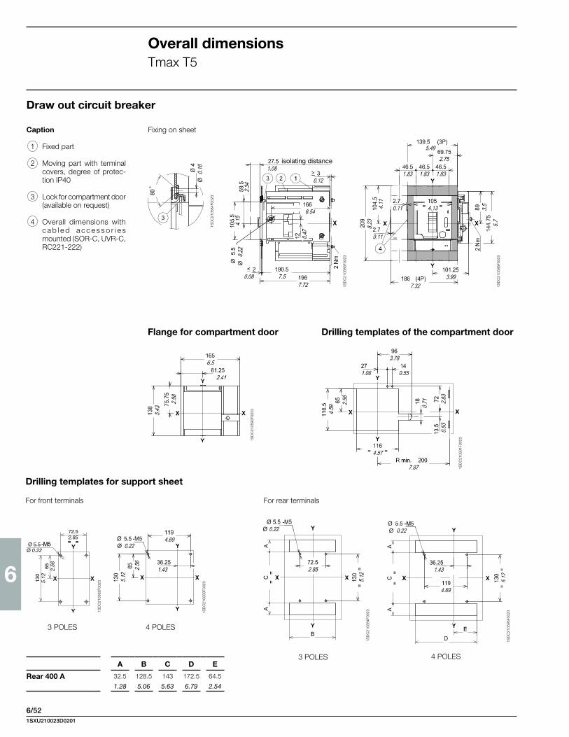
6
6/52
Draw out circuit breaker
Flange for compartment door
Fixing on sheet
Drilling templates of the compartment door
Caption
1 Fixed part
2 Moving part with terminal covers, degree of protec-tion IP40
3 Lock for compartment door (available on request)
4 Overall dimensions with c a b l e d a c c e s s o r i e s mounted (SOR-C, UVR-C, RC221-222)
Overall dimensionsTmax T5
Drilling templates for support sheet
For front terminals For rear terminals
3 POLES 4 POLES
3 POLES 4 POLES
1SD
C21
0585
F002
3
1SD
C21
0584
F002
3
1SD
C21
0586
F002
3
isolating distance
1SD
C21
0590
F002
3
1SD
C21
0591
F002
3
1SD
C21
0592
F002
3
1SD
C21
0593
F002
3
1SD
C21
0594
F002
3
1SD
C21
0595
F002
3
A B C D E
Rear 400 A 32.5 128.5 143 172.5 64.5
1.28 5.06 5.63 6.79 2.54
1SXU210023D0201

6
6/53
1SD
C21
0600
F002
3
1SD
C21
0601
F002
3
Terminals
Caption
1 Front terminals for copper cables
2 Front terminals for copper/aluminium cables
3 Terminals with degree of protection IP40
Front for cables Cu and Cu/Al 400 A - FC Cu - FC Cu/Al
1SD
C21
0596
F002
3
1SD
C21
0597
F002
3
Extended front - EF
1SXU210023D0201

6
6/54
Overall dimensionsTmax T5
1SD
C21
0605
F002
3
1SD
C21
0606
F002
3
1SD
C21
0607
F002
31S
DC
2106
10F0
023
1SD
C21
0608
F002
3
1SD
C21
0609
F002
3
Rear flat horizontal - HR
Rear flat vertical - VR
Terminals
1SXU210023D0201

6
6/55
41S
DC
210J
78F0
001
1SD
C21
069A
F000
1
1SD
C21
070A
F000
1
140
120
8.5 - M8
214
144
77.5
77.5
2R5.51
4.72
0.33 - M8
8.43
5.67
3.05
3.05
0.08R
210
120
8.5 - M8
107
144
77.5
77.5
2R70
4.72
0.33 - M8
284
8.27
4.21
2.76
11.15
5.67
3.05
3.05
0.08R
1SD
C21
071A
F000
1
1SD
C21
072A
F000
1
Draw out circuit breaker
Fixing on sheetCaption
1 Cradle
2 Moving part
3 Lock for compartment (available on request)
4 Overall dimensions with cabled accessories mount-ed (SOR-C, UVR-C)
Drilling templates of the compartment doorFlange for compartment door
Drilling templates for support sheet
3 POLES4 POLES
Overall dimensionsTmax T6
3
27.5 isolating distance1.08
84.5
140
5 0.20
≤ 2 190.5
196
167
145
208
295
5.71
8.19
11.6
1
35.5≤ 0.08 7.5
7.72
6.57
1.4
0.12
3.33
5.51
7070
280 (4P)
210 (3P)
273
10.7
5
136.5123.5
193.55.374.86
7.62
77
144.
753.03
5.7
702.762.76
11.02 (4P)
8.27 (3P)
2.76
4
100.
25
173 3.
95
6.81
75.25
210
2.96
8.27
150
=
=148.5
89.5
43 14
96.5
200R min.
18.5
122
18
5.85
1.69 0.55
7.87R min.
4.8
0.71
32
5.91 3.
52 3.8
0.73
1.26
1SD
C21
067A
F000
1
1SD
C21
068A
F000
1
1SXU210023D0201

6
6/56
1SD
C21
0J86
F000
1
1SD
C21
078A
F000
1
1SD
C21
0J89
F000
1
1SD
C21
077A
F000
1
Front extended - EF
Rear flat horizontal - HR
Rear flat vertical - VR
3-4 POLES
3-4 POLES
Terminals
Overall dimensionsTmax T6
3
10
310.12
0.39
1.22
7070
172
.5
14
40
20
6.79
0.79
702.762.76
0.55
1.57
2.76
80.53.17
100.
39
30.12
7070
14
40200.
79
702.762.76
0.55
1.57
2.76
40
14
2080.53.17
1.57
30.12 0.79
0.55
7070 702.762.76
0.39
2.76 10
1SD
C21
073A
F000
1
1SD
C21
074A
F000
1
1SD
C21
075A
F000
1
1SD
C21
076A
F000
1
1SXU210023D0201

6
6/57
1SD
C21
080A
F000
1 1SD
C21
082A
F000
1
1SD
C21
083A
F000
1
1SD
C21
084A
F000
1
1SD
C21
085A
F000
1
Rear flat vertical - VR Rear flat horizontal - HR
Draw out circuit breaker
Fixing on sheet
Caption
1 Compartment door with flange sheet drilling
2 Rear segregation for rear terminals
3 Flange for compartment door
4 Flange fixing screws
5 Tightening torque: 1.5 Nm
6 Drilling template for fixing onto support sheet
7 Tightening torque: 21 Nm
8 Front terminals
9 Rear horizontal terminals
10 Rear vertical terminals
11 Rear segregation for front terminals
12 Flange for compartment door
13 Auxiliary contact terminal
14 Insulating protection
15 Rear spread terminals (4 poles)
16 Tightening torque 18 Nm
17 Rear spread terminals (3 poles)
Rear spread terminal - RS
Overall dimensionsTmax T7
70 70 702.76 2.762.76
14
13
348
278
155.5
4425
13.7
10.94
6.12
1.730.98
25
12.5
239.
5
Ø 11
554
21.8
1
0.98
0.49
9.43
Ø 0.43
138
3
11
14
7
4 5
D
251
15
35
9.88
0.59
1.38
42
343
159.
56.
28
363.
25
154 104.54.11
49
47
2
6.06
1.93
1.85
0.08
? 3
1.65
13.5 14
.3
? 0.
12
99
198
44
198
9915
7.8
1.73
3.9
3.9
0.59
7.8
29
14
20
1.14
0.55
0.79
25 0.98
10
2 2
9
140.55
16
243
121.
515
9.57
4.78
0.59
1SD
C21
079A
F000
1
1SD
C21
081A
F000
1
2068.11
36
15
1.42
0.5925 44
0.98 1.73
16.5
290.
65
1.14
9 110.43
41.5
1.63
59
41.5
17
9090
25 25 25Ø 11
3.543.54
0.98 0.98 0.98Ø 0.43
90
77.5 3.54
3.05
1.632.
32
9090 90
25 25 25 25
67 2.64
Ø 11
90
80.5 3.54
3.17
2.50.1
15
3.54 3.543.54
0.98 0.98 0.98 0.98
Ø 0.43
1SXU210023D0201

6
6/58
1SD
C21
088A
F000
1
1SD
C21
0L57
F000
1
1SD
C21
091A
F000
1
1SD
C21
089A
F000
1
Drilling templates of the compartment door
Drilling templates for support sheet
Overall dimensionsTmax T7
Caption
1 Drilling a hole in the sheet metal door to the compart-ment with the flange for the VR-HR-EF-ES terminals
2 Rear segregation for rear terminals
3 Drilling a hole in the sheet metal door to the compart-ment with the flange for the RS terminals
5 Tightening torque: 1.5 Nm
6 Drilling template for fixing onto support sheet
11 Rear segregation for front terminals
12 Flange for compartment door
14 Insulating protection
Draw out circuit breaker
Terminals - ES
Standard Ronis Profalux Kirk Castell
D 287 291 299 298 328
11.3 11.46 11.77 11.73 12.91
1SD
C21
087A
F000
1
III IV
A 160 230
6.3 9.05
B 206 276
8.11 10.87
C 219 289
8.62 11.38
1.85
363.
2581.5
1.42
34813.7 305
12.0127810.94
100.39
100.39
100.39
702.76
702.76
953.74
100.39
150.59
1907.482068.11
36
150.59
14.50.57
343
13.5 3.
21
159.
56.
2811
04.
3337
.51.
4837
.51.
48
14.3
0 102
4.02
204
8.03
2499.8275.510.85
D
47
491.93
64.52.54
30.
12
20.08
421.65
1SD
C21
086A
F000
1 256.
5 144.
5
16.2
5
160.
7516
0.75
10.1
5.69 0.
64
6.33
6.33
153.756.05
R min 200R min 7.87
153.756.05
26.251.03
278.510.96
165.56.52 Ø 4
Ø 0.16
Ø 6.5
Ø 0.26
109.54.31
1034.06
199
7.83
99.5
3.92 14
05.
5128
011
.02
16.2
5
160.
7516
0.75
Ø 4 N° 8
R min=200
146.75 146.75
278.526.25
165.5
Ø 0.16 N° 8
R min=7.87
5.78 5.78
10.961.03
6.52
256.
5 144.
510
.1
5.69 0.
64
6.33
6.33
X X
Y
Y3
11
14
5020
103
109.5
1.970.79
4.06
4.31
100 30
99.519
9
460
230
115
3.94 1.
183.
92
7.83
18.1
1
9.06
4.53
C
B
Ø 7
Ø0.28
803.1510
03.
94
Ø10Ø0.39
320.512.62
336.
513
.25
1345.28
152
5.98
1SD
C21
092A
F000
1
1SXU210023D0201

6
6/59
1SD
C21
095A
F000
1
1SD
C21
096A
F000
1
1SD
C21
098A
F000
1
1SD
C21
097A
F000
1
Overall dimensionsTmax T7M
Front extended - EF
Draw out circuit breaker
Rear flat vertical - VR Rear flat horizontal - HR
Caption
1 Compartment door steel sheet drilling for flange
2 Rear segregation for rear terminals
3 Flange for the compartment door
4 Flange fixing screws
5 Tightening torque: 1.5 Nm
7 Key lock (optional)
8 Padlock (optional)
9 Tightening torque: 21 Nm
10 Front terminal
11 Rear horizontal terminal
12 Rear vertical terminal
13 Rear segregation for front terminals
14 Flange for compartment door
15 Overall dimensions of the auxiliary contact terminals
16 Insulating protection
17 Rear spread terminals (4 poles)
18 Tightening torque 18 Nm
19 Rear spread terminals (3 poles)
Rear spread terminal - RS
70 70 702.76 2.76 2.76
348
278
155.5
4425
25
12.5
554
0.98
0.49
21.8
1
13.7
10.94
6.12
Ø 11
1.730.98
Ø 0.43
16
15
30512.01
42
159.
5
363.
25
154
49
? 3
E
343
249
275.5
D
47
64.5
21.65
6.06
1.93
9.8
10.85
1.85
2.54
0.08
351.38
204
102
6.28
14.3
? 0.
12
13.5
8.03
4.02
1510
13
16
3
4 5
9
7
8
1SD
C21
093A
F000
1
1SD
C21
094A
F000
1
2 2
1211
29
14
20
1.14
0.55
0.79
198
2544
99
198
99
15
7.8
0.98
1.73
3.9
7.8
3.9
0.59
Ø11Ø0.4
3
18
243
121.
515
9.57
4.78
0.59
206
35
15
190
8.11
1.38
0.59
7.48
44
16.5
Ø11251.730.98
Ø0.43 0.65
29 1.14
41.5
1.63
59
41.5
19
9090
25 25 25Ø 11
3.543.54
0.98 0.98 0.98Ø 0.43
90
77.5 3.54
3.05
1.632.
32
9090 90
25 25 25 25
67 2.64
Ø 11
90
80.5 3.54
3.17
2.50.1
17
3.54 3.543.54
0.98 0.98 0.98 0.98
Ø 0.43
1SD
C21
099A
F000
1
1SXU210023D0201

6
6/60
1SD
C21
002B
F000
1
1SD
C21
001B
F000
1
1SD
C21
089A
F000
1
Drilling templates of the compartment door
Overall dimensionsTmax T7M
Caption
1 Drilling a hole in the sheet metal door to the compart-ment with the flange for the VR-HR-EF-ES terminals
2 Rear segregation for rear terminals
3 Drilling a hole in the sheet metal door to the compart-ment with the flange for the RS terminals
6 Drilling template for fixing onto support sheet
13 Rear segregation for front terminals
14 Flange for compartment door
16 Insulating protection
Drilling templates for support sheet
1.85
363.
2581.5
1.42
34813.7 305
12.0127810.94
100.39
100.39
100.39
702.76
702.76
953.74
100.39
150.59
1907.482068.11
36
150.59
14.50.57
343
13.5 3.
21
159.
56.
2811
04.
3337
.51.
4837
.51.
48
14.3
0 102
4.02
204
8.03
2499.8275.510.85
D
47
491.93
64.52.54
30.
12
20.08
421.65
278.510.96
165.56.52
26.251.03
153.756.05
153.756.05
1034.05
109.54.31 320.5
12.621345.28
336.
513
.25
152
5.98
280
11.0
2
140
5.51
99.5
3.91
199
7.83
160.
756.
3316
0.75
6.33
16.2
50.
64
144.
55.
69
256.
510
.1
R min 200R min 7.87
Ø 6.5
Ø 0.26
16.2
5
160.
7516
0.75
Ø 4 N° 8
R min=200
146.75 146.75
278.526.25
165.5
Ø 0.16 N° 8
R min=7.87
5.78 5.78
10.961.03
6.52
256.
5 144.
510
.1
5.69 0.
64
6.33
6.33
X X
Y
Y3 1S
DC
2100
1BF0
001
13
16
C
B
3099
.5
199
460
230
115
1.18
3.92
7.83
18.1
1
9.06
4.53
Ø 7
Ø0.28
5020
103
1.970.79
4.06
109.54.31
803.1510
03.
94
Ø10Ø0.39
278.510.96
165.56.52
26.251.03
153.756.05
153.756.05
1034.05
109.54.31 320.5
12.621345.28
336.
513
.25
152
5.98
280
11.0
2
140
5.51
99.5
3.91
199
7.83
160.
756.
3316
0.75
6.33
16.2
50.
64
144.
55.
69
256.
510
.1
R min 200R min 7.87
Ø 6.5
Ø 0.26
Standard Ronis Profalux Kirk Castell
D 290 298 306 – –
11.42 11.73 12.05 – –
E 287 291 299 298 328
11.3 11.46 11.77 11.73 12.91
III IV
A 160 230
6.3 9.05
B 206 276
8.11 10.87
C 219 289
8.62 11.38
1SD
C21
090A
F000
1
1SD
C21
086A
F000
1
1SXU210023D0201

6
6/61
1SD
C21
004B
F000
1
1SD
C21
004B
F000
1
1SD
C21
004B
F000
1
Overall dimensionsCircuit breaker with RC221/222 residual current releaseTmax T1 with RC222 for 200 mm module
Fixed version
Front terminals - F Fixing on sheetCaption
1 Depth of the switchboard with circuit breaker face extending
2 Depth of the switchboard with circuit breaker face flush with door
3 Terminal covers with degree of protection IP40
Drilling templates of the compartment door
Drilling templates for support sheet
For A = 71 - without flange For A = 79 - without flange
3 1.1 Nm 7 Nm
153.26.03
101.23.98
38.11.5
76.23
168.26.62
250.98
250.98
250.98
65 2.56
155.
56.
12
1024.02
24.50.96
702.76
30.12
20.08
17 0.67
45 1.7710
44.
0952 2.05
11.5
0.45
1SD
C21
003B
F000
1
116.14.57
39.11.54
180.
71
47 1.85
116.14.57
18 0.71
47 1.85
542.13
78.23.08
87.53.44
250.98
250.98
107
4.21
53.5
2.11
Ø 4.5 - M4Ø 0.18 - M4
116.14.57
39.11.54
180.
71
47 1.85
116.14.57
18 0.71
47 1.85
542.13
78.23.08
87.53.44
250.98
250.98
107
4.21
53.5
2.11
Ø 4.5 - M4Ø 0.18 - M4
116.14.57
39.11.54
180.
71
47 1.85
116.14.57
18 0.71
47 1.85
542.13
78.23.08
87.53.44
250.98
250.98
107
4.21
53.5
2.11
Ø 4.5 - M4Ø 0.18 - M4
1SXU210023D0201

6
6/62
T1
T2
T3
Overall dimensionsT1, T2 and T3 with residual current release - RC221/RC222
Fixed version
Front - FCaption
1 Depth of the switchboard with circuit breaker face extending
2 Depth of the switchboard with circuit breaker face flush with door
3 Front terminals for cable connection
4 Low terminal covers with degree of protection IP40
5 Insulating plate
Fixing on sheet
1SD
C21
0164
F000
3
1SD
C21
0165
F000
3
222
8.74
222
8.74
1SD
C21
0166
F000
3
1SXU210023D0201

6
6/63
T1 T2 T3
T1 - T2 - T3
1SD
C21
0655
F002
3
1SD
C21
0655
F002
3
1SD
C21
0655
F002
3
1SD
C21
0655
F002
3
1SD
C21
0655
F002
31S
DC
2106
55F0
023
1SD
C21
0655
F002
3
1SD
C21
0655
F002
3
Flange for the compartment door
3 POLES
4 POLES
Drilling template for fixing sheet
3 POLES 4 POLES
A B C D E F
T1 124 107 53.5 78.1 25 53.1
4.88 4.21 2.11 3.07 0.98 2.09
T2 124 107 53.5 90 30 60
4.88 4.21 2.11 3.54 1.18 2.36
T3 141.5 122 61 102.5 35 67.5
5.57 4.80 2.40 4.04 1.38 2.66
1SXU210023D0201

6
6/64
T1 - T2 - T3 T1 T1 - T2 - T3
B
A
H
T2 - T3
T1 - T2 - T3 T1 - T2 - T3 T1 - T2 - T3
B
A
H
B
AH
B
A
H
B
A
H
BA
H
B
A
H
1SD
C21
0656
F002
3
4 POLES
1SD
C21
0656
F002
3
1SD
C21
0656
F002
3
1SD
C21
0656
F002
3
1SD
C21
0656
F002
3
1SD
C21
0656
F002
3
1SD
C21
0656
F002
3
Fixed version Drilling templates of the compartment door
3 POLES
Without flange face extending
Without flange face not extending
With flangeface not extending
Overall dimensionsT1, T2 and T3 with residual current release - RC221/RC222
A B C D E F G H
T1 18 108.2 94.1 – 23.5 113 78.1 39.1
0.71 4.26 3.70 – 0.93 4.45 3.07 1.54
T2 18 122 106 76 23.5 120 90 46
0.71 4.80 4.17 2.99 0.93 4.72 3.54 1.81
T3 13.5 137 118.5 83.5 19 127.4 102.5 53.5
0.53 5.39 4.67 3.29 0.75 5.02 4.04 2.11
1SXU210023D0201
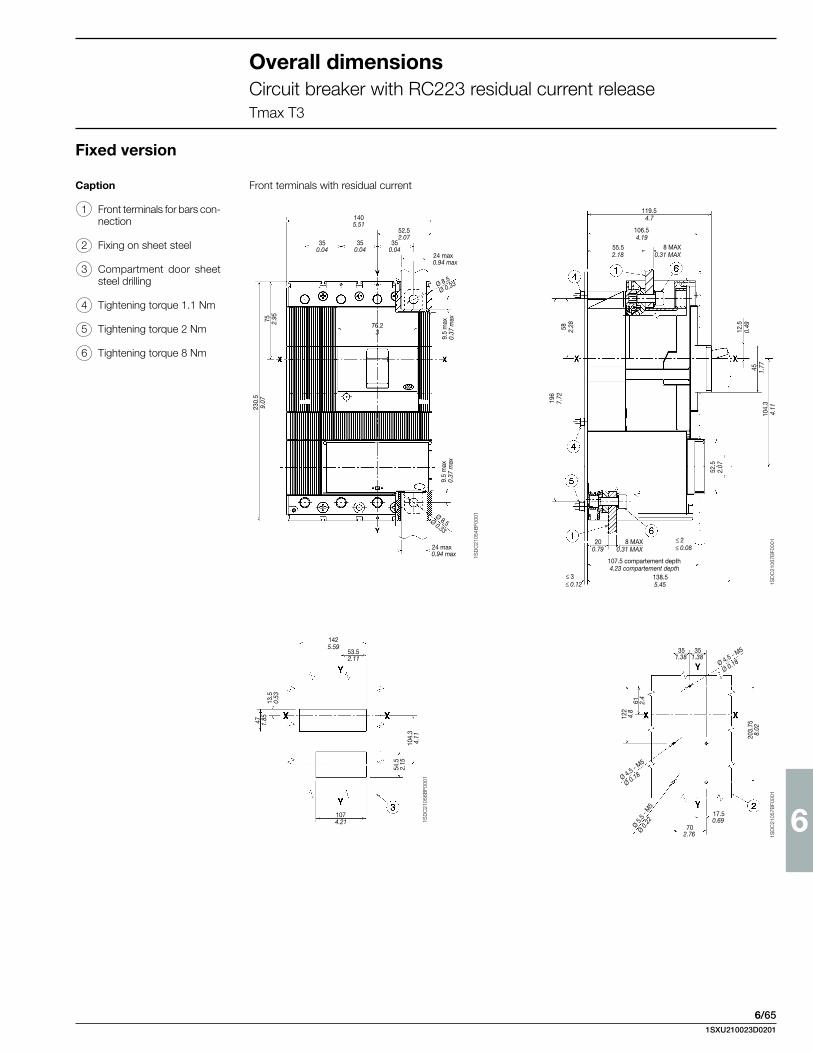
6
6/65
1SD
C21
054B
F000
1
1SD
C21
056B
F000
1
1SD
C21
057B
F000
1
1405.51
52.52.07
350.04
350.04
350.04
24 max0.94 max
Ø 8.5
Ø 0.33
9.5
max
0.37
max75 2.95
76.23
230.
59.
07
24 max0.94 max
9.5
max
0.37
max
Ø 8.5Ø 0.33
1425.59
53.52.11
1074.21
47 1.85
13.5
0.53
54.5
2.15
104.
34.
11 203.
758.
02
122
4.8
61 2.4
351.38
351.38
702.76
17.50.69
Ø 5.5
- M
5
Ø 0.2
2
Ø 4.5 - M5
Ø 0.18
Ø 4.5 - M5
Ø 0.18
119.54.7
106.54.19
55.52.18
8 MAX0.31 MAX
8 MAX0.31 MAX
200.79
107.5 compartement depth4.23 compartement depth
138.55.45
≤ 3≤ 0.12
≤ 2≤ 0.08
52.5
2.07
104.
34.
11
45 1.77
12.5
0.4958 2.28
196
7.72
1SD
C21
067B
F000
1
Overall dimensionsCircuit breaker with RC223 residual current releaseTmax T3
Fixed version
Caption
1 Front terminals for bars con-nection
2 Fixing on sheet steel
3 Compartment door sheet steel drilling
4 Tightening torque 1.1 Nm
5 Tightening torque 2 Nm
6 Tightening torque 8 Nm
Front terminals with residual current
1SXU210023D0201

6
6/66
Overall dimensionsCircuit breaker with RC211/3 and RC 212/3 residual current releaseTmax Ts3
1SD
C21
0Z70
F000
1
1SD
C21
0Z71
F000
3
Mounting on sheet metal
Front terminals for cables(terminal covers to order)
(*) without terminal covers(**) with low terminal covers(***) with high terminal covers
Rear terminals(low terminal covers included in supply)
Terminals for rear Cu/Al cables (high terminal covers included in supply)
Version with extended front terminals
Template for drilling sheet metal support(minimum thickness of sheet metal: 0.12”/3 mm)
Template for drilling compartment door and fitting flange(thickness of sheet metal: 0.06÷0.08”/1.5÷2 mm)
Holes for threaded rear terminals only
Holes for rear terminals for cables only
Vertical installation
1SD
C21
0Z72
F000
3
Caption
1 Tightening torque 2 Nm
2 Flange for compartment door
Note See the various different versions for the dimen-sions of the terminals
1SXU210023D0201

6
6/67
Horizontal installation
1SD
C21
0Z73
F000
1
2
1
=
=
SACE S3
I
O
o
offX1
Y
Y
=
=
X1 X1 X1
1405.51
351.38
351.38
351.38
1405.51
170
6.69
97.5
3.84
250.98
45 1.77
501.97
1084.25
3.50.14
Caption
1 Front terminals for cables
2 Bracket for mounting on DIN EN 50023 channel
1SXU210023D0201

6
6/68
T4 T5 (400 A)
1SD
C21
0658
F002
3
1SD
C21
0657
F002
3
1SD
C21
0659
F002
3
1SD
C21
0660
F002
3
1SD
C21
0661
F002
3
1SD
C21
0662
F002
3
1SD
C21
0663
F002
3
1SD
C21
0664
F002
3
T4 T5
1SD
C21
0665
F002
3
1SD
C21
0666
F002
3
Caption
1 Overall dimensions with cabled auxiliary contacts mounted (only 3Q 1SY)
Flange for the compartment door Drilling templates of compartment door and fitting flange
Drilling templates for support sheet
For circuit breakers
For residual current release
With flange Without flange
Front - F Fixing on sheet
Overall dimensionsT4 and T5 with residual current release - RC221/RC222
Fixed version
1SXU210023D0201

6
6/69
T4 T5 (400 A)
Front - F Fixing on sheet
Plug-in version
1SD
C21
0670
F002
3
1SD
C21
0669
F002
3
1SD
C21
0668
F002
3
1SD
C21
0667
F002
3
1SD
C21
0671
F002
3
1SD
C21
0672
F002
3
1SD
C21
0673
F002
3
1SD
C21
0674
F002
3
1SD
C21
0675
F002
3
1SD
C21
0676
F002
3
T4 T5
Caption
1 Fixed part
2 Mobile part
3 Overall dimensions with cabled auxiliary contacts mounted (only 3Q 1SY)
Flange for the compartment door Drilling templates of compartment door and fitting flange
With flange Without flange
Drilling templates for support sheet
For circuit breakers
For residual current release
1SXU210023D0201

6
6/70
Overall dimensionsAccessories for Tmax T1 - T2 - T3
Fixed version
Flange for compartment door
Solenoid operator superimposed
Drilling templates of the compartment door
Without flangeOperating mechanism face extending
Without flange Operating mechanism face flush with door
With flange Operating mechanism face flush with door
A B C
T1 33.5 18 23.5
1.32 0.71 0.93
T2 33.5 18 23.5
1.32 0.71 0.93
T3 29 13.5 19
1.14 0.53 0.75
T1 T2
T3
1SD
C21
0677
F002
3
1SD
C21
0678
F002
3
1SD
C21
0679
F002
3
1SD
C21
0681
F002
3
1SD
C21
0680
F002
3
Caption
1 Depth of the switchboard with operating mechanism face extending
2 Depth of the switchboard with operating mechanism face flush with door
3 Low terminal covers with degree of protection IP40
4 Insulating plate
1SD
C21
0682
F002
3
1SD
C21
0683
F002
3
1SXU210023D0201

6
6/71
T1
1SD
C21
015B
F000
1
1SD
C21
017B
F000
1
1SD
C21
018B
F000
1
1SD
C21
017B
F000
1
Caption
1 Circuit breaker face extend-ing
2 Circuit breaker face flush with door
3 Low terminal covers with degree of protection IP40
Solenoid operator side by side
3 POLES
4 POLES
Drilling templates for fixing sheet Drilling templates of the compartment door
A B
3P 79 161.3
3.11 6.35
71 161.3
2.79 6.35
4P 79 161.3
3.11 6.35
71 161.3
2.79 6.35
250.98
250.98
250.98
76.23
101.23.98
83.13.2776.2
3
134
5.28
67 2.64
17 0.67
45 1.77
1054.13
702.76
30.12 0.08
2
1SD
C21
016B
F000
1
250.98
38.11.5
652.26
250.98
38.11.5
652.26
Ø 4.5 - M4Ø 0.18
107
4.21
53.5
2.11
41.5
1.63
83 3.27
41.5
1.63
83 3.2710
74.
2153
.52.
11
Ø 4.5 - M4Ø 0.18
250.98
38.11.5
652.26
250.98
38.11.5
652.26
Ø 4.5 - M4Ø 0.18
107
4.21
53.5
2.11
41.5
1.63
83 3.27
41.5
1.63
83 3.2710
74.
2153
.52.
11
Ø 4.5 - M4Ø 0.18
122.24.81
180.
71
47 1.85
1SXU210023D0201

6
6/72
T2
1SD
C21
020B
F000
1
1SD
C21
021B
F000
1
1SD
C21
022B
F000
1
1SD
C21
021B
F000
1
Caption
1 Circuit breaker face extend-ing
2 Circuit breaker face flush with door
3 Low terminal covers with degree of protection IP40
Solenoid operator side by side
Drilling templates for fixing sheet Drilling templates of the compartment door
3 POLES
4 POLES
Fixed version
Overall dimensionsAccessories for Tmax T1 - T2 - T3
A B
3P 79 161.3
3.11 6.35
71 161.3
2.79 6.35
4P 79 161.3
3.11 6.35
71 161.3
2.79 6.35
1204.72
903.54
301.18
301.18
301.18
76.23
76.23
134
5.28
67 2.68
17 0.67
45 1.77
1054.1370
2.76
30.12 0.08
2
301.18
35.61.4
652.26Ø 4.5 - M4
Ø 0.18
107
4.21
53.5
2.11
41.5
83 3.27
1.63
301.18
35.61.4
652.26
Ø 0.18
107
4.21
53.5
2.11
41.5
83 3.27
1.63
Ø 4.5 - M430
1.18
301.18
35.61.4
652.26Ø 4.5 - M4
Ø 0.18
107
4.21
53.5
2.11
41.5
83 3.27
1.63
301.18
35.61.4
652.26
Ø 0.18
107
4.21
53.5
2.11
41.5
83 3.27
1.63
Ø 4.5 - M430
1.18
122.24.81
180.
71
47 1.85
1SD
C21
019B
F000
1
1SXU210023D0201

6
6/73
Rotary handle operating mechanism on the compartment door
A B
T1-T2 28 14
1.10 0.55
T3 32.5 9.5
1.28 0.37
470.518.52
with6.3 (7.01 with IP54)
60.5 (87 with IP54)2.38 (3.43 with IP54)
1SD
C21
0684
F002
3
1SD
C21
0685
F002
3
1SD
C21
0686
F002
3
1SD
C21
0687
F002
3
Caption
1 Transmission unit
2 Rotary handle operating mechanism on the com-partment door
3 Insulating plate
Drilling template of the compartment door
Minimum rotation radius for door fulcrum
Heights for door with maximum distance
Heights for door with minimum distance
1SXU210023D0201
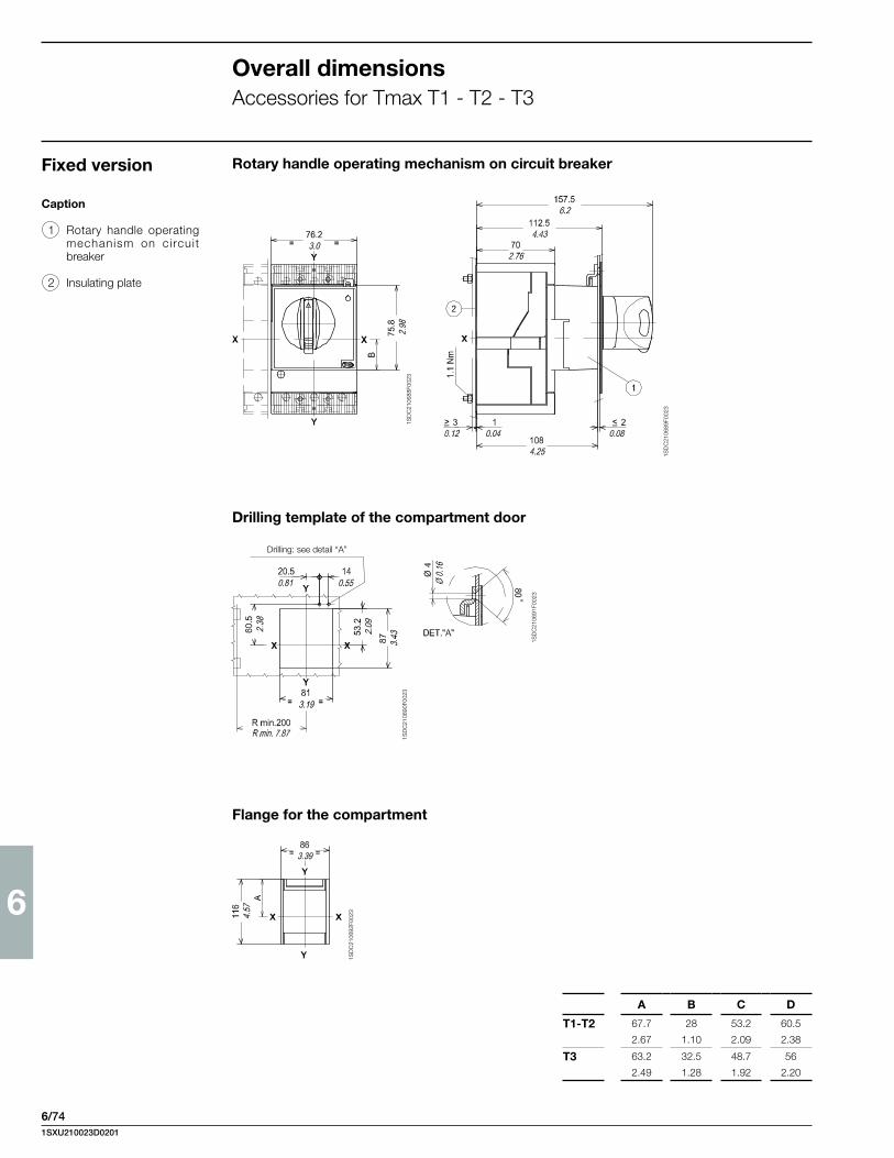
6
6/74
1SD
C21
0688
F002
3
1SD
C21
0689
F002
3
1SD
C21
0691
F002
3
1SD
C21
0690
F002
3
1SD
C21
0692
F002
3
Caption
1 Rotary handle operating mechanism on circui t breaker
2 Insulating plate
Rotary handle operating mechanism on circuit breaker
Drilling template of the compartment door
Flange for the compartment
Drilling: see detail “A”
Overall dimensionsAccessories for Tmax T1 - T2 - T3
A B C D
T1-T2 67.7 28 53.2 60.5
2.67 1.10 2.09 2.38
T3 63.2 32.5 48.7 56
2.49 1.28 1.92 2.20
Fixed version
1SXU210023D0201
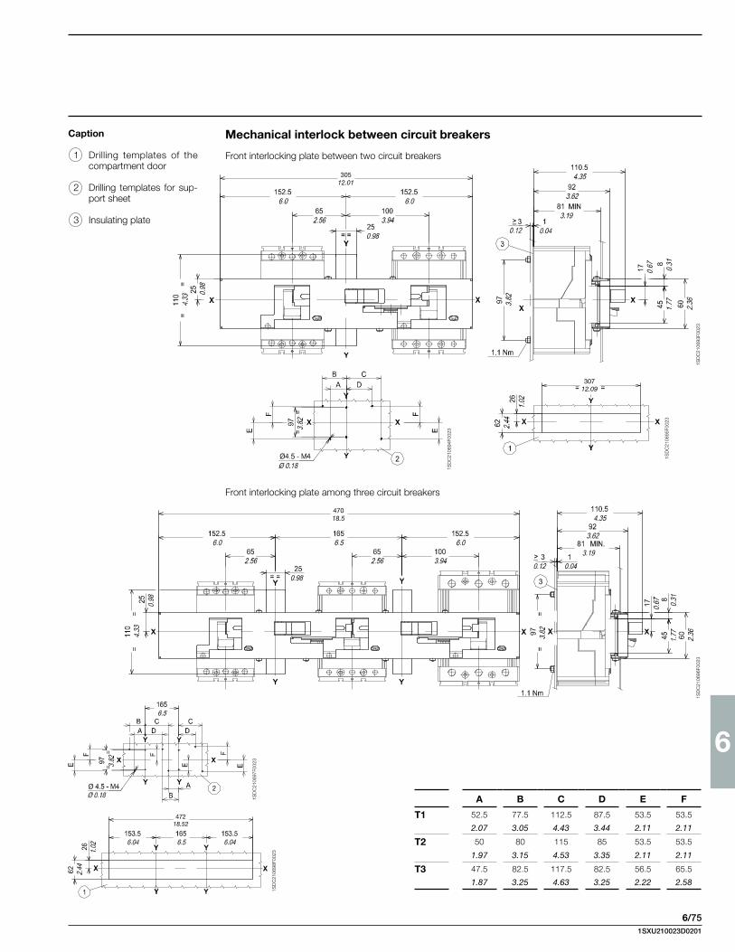
6
6/75
Front interlocking plate between two circuit breakers
Mechanical interlock between circuit breakers
A B C D E F
T1 52.5 77.5 112.5 87.5 53.5 53.5
2.07 3.05 4.43 3.44 2.11 2.11
T2 50 80 115 85 53.5 53.5
1.97 3.15 4.53 3.35 2.11 2.11
T3 47.5 82.5 117.5 82.5 56.5 65.5
1.87 3.25 4.63 3.25 2.22 2.58
30512.01
30712.09
47018.5
47218.52
1SD
C21
0693
F002
3
1SD
C21
0694
F002
3
1SD
C21
0695
F002
3
1SD
C21
0696
F002
3
1SD
C21
0697
F002
3
1SD
C21
0698
F002
3
Front interlocking plate among three circuit breakers
Caption
1 Drilling templates of the compartment door
2 Drilling templates for sup-port sheet
3 Insulating plate
1SXU210023D0201
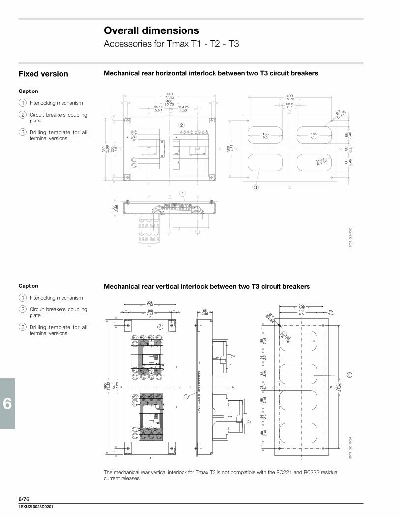
6
6/76
Overall dimensionsAccessories for Tmax T1 - T2 - T3
44017.32400
15.7599.253.91
134.255.28
2
330
12.9
930
011
.81
65 2.56
13
300
11.8
1
1656.5
1656.5
40015.7568.52.7
88 3.46
88 3.46
56 2.2
Ø 7
Ø 0.28
R 30
R 1.18
Mechanical rear horizontal interlock between two T3 circuit breakers
Caption
1 Interlocking mechanism
2 Circuit breakers coupling plate
3 Drilling template for all terminal versions
The mechanical rear vertical interlock for Tmax T3 is not compatible with the RC221 and RC222 residual current releases
Mechanical rear vertical interlock between two T3 circuit breakersCaption
1 Interlocking mechanism
2 Circuit breakers coupling plate
3 Drilling template for all terminal versions
Z
Z
K K K K
Z
Z
K K
== =
=
= =
==
==
=
=
1
= =
=
=
==
==
30R
3
2
2288.98
1907.48
540
21.2
6
590
23.2
3
88 3.46
56 2.2
88 3.46
88 3.46
28 1.1
88 3.46
56 2.2
540
21.2
6
652.56
1907.481656.5
250.98Ø 7Ø 0.28
R 1.18
1SD
C21
0L94
F000
11S
DC
2109
61F0
004
Fixed version
1SXU210023D0201
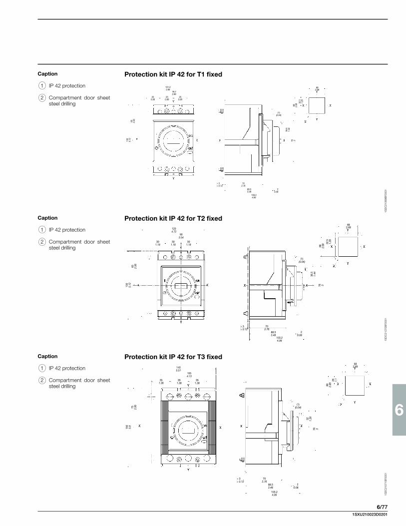
6
6/77
Caption
1 IP 42 protection
2 Compartment door sheet steel drilling
1SD
C21
069B
F000
1
Protection kit IP 42 for T1 fixed
1SD
C21
070B
F000
11S
DC
2107
1BF0
001
Protection kit IP 42 for T2 fixed
Protection kit IP 42 for T3 fixed
Caption
1 IP 42 protection
2 Compartment door sheet steel drilling
Caption
1 IP 42 protection
2 Compartment door sheet steel drilling
101.23.98
76.22.99
250.98
250.98
250.98
65 2.56
130
5.12
702.76
88.53.48
103.24.06
(1)(0.04)
36.5
1.44
76 3
682.68
68 2.68
32.5
1.28
20.08
> 3> 0.12
1204.72
903.54
301.18
301.18
301.18
65 2.56
130
5.12
702.76
88.53.48
103.24.06
(1)(0.04)
36.5
1.44
76 3
682.68
68 2.68
32.5
1.28
20.08
> 3> 0.12
1405.51
1054.13
351.38
351.38
351.38
75 2.95
150
5.9
702.76
88.53.48
103.24.06
(1)(0.04)
32 1.26
76 3
682.68
68 2.68
28 1.1
20.08
> 3> 0.12
1SXU210023D0201

6
6/78
Overall dimensionsAccessories for Tmax Ts3
1SD
C21
0Z77
F000
1
Y
Y
X
= =
= =
=
=
=
=
X
=
=
=
Y
Y
C
B= =
A
= =
31
2
=
A
(4 POLES)
(3 POLES)269.510.61
27.51.08
20.08
105
4.13 16
16.
34
1174.61
1124.41
1124.41
Ø 7Ø 0.28
1425.59
803.15
1SD
C21
0Z78
F000
1
Y
Y
X
=
=
Nr. 3 Ø 8Ø 0.31
=
=
R min. 2007.87
X
=
=
Y
Y
=
=
C
B= =
A
2
1
(4 POLES)
(3 POLES)
27.51.08
269.510.61
161
6.34
27.2
51.
07
126
4.96
142
5.59
1.750.07
1355.31
813.19
1254.92
160.63
943.70
632.48
ø5.5ø0.22
105
4.13
1676.57
78.53.09
963.78
20.08
Ø 7Ø 0.28
Ø 7Ø 0.28
1SD
C21
0Z79
F000
1
Y
Y
X
= =
= =
=
=
=
=
3
X
=
=
Y
Y
C
B= =
= =
1
2
(4 POLES)
(3 POLES)
A
2208.66
20.08
225.58.88
161
6.34
1054.13
1174.61
1124.4180
3.15
112
4.41
142
5.59
Ø 7Ø 0.28
Motor operator for fixed circuit breaker
Motor operator for plug in circuit breakers
Motor operator for draw out circuit breaker
isolating stroke
Note See the various differ-ent versions for the circuit breaker mounting holes
Caption
1 Flange for compartment door
2 Dimensions with connectors
3 Dri l l ing of compartment door
Note See the various differ-ent versions for the circuit breaker mounting holes
Caption
1 Flange for compartment door
2 Dimensions with connectors
3 Dri l l ing of compartment door
Note See the various differ-ent versions for the circuit breaker mounting holes
Caption
1 Flange for compartment door
2 Dri l l ing of compartment door
isolating stroke
A B C
Ts3 140 105 585.51 4.13 2.28
A B C
Ts3 140 105 585.51 4.13 2.28
A B C
Ts3 140 105 585.51 4.13 2.28
1SXU210023D0201

6
6/79
1SD
C21
0Z80
F000
11S
DC
210Z
81F0
001
Y
B B B C B B B
A
X
E
D
F
G
Y
H15 4
Y
Y
X X
M
NP
N
Q
RL
I
1
Y
Y
(S5) (S3-S4)
= =
= =
= =
R
=
=
O
2 3
27.51.08
Ø 7Ø 0.28
275
10.8
3
105
4.13
103.
54.
07
65 2.56
E
5
=
=
1
Y
X X
=
=
D
C
F
G
F
G
4B
Y
Y
Y
2 3
I
HN
= =
= =
O
Nr. 8 Ø 7Ø 0.28
=
=
BB
A
M
M
N
M
M
N
P
P
Q
R
103.54.07
105
4.13
105
4.13
652.56
27510.83
27.51.08
11.50.45isolating stroke
Interlock across two horizontally-installed circuit breakers
Interlock across two vertically-installed circuit breakers
Note See the various different versions for the dimensions of the circuit breakers
Caption
1 Interlock device
2 Template for drilling mounting holes in sheet metal
3 Drilling template for all ver-sions with rear terminals
4 Dimensions with four-pole draw out version mounted on right
5 Tightening torque 3.7 Nm
Note See the various different versions for the dimensions of the circuit breakers
Caption
1 Interlock device
2 Drilling template for mounting circuit breakers on sheet metal
3 Drilling template for all ver-sions with rear terminals
4 Dimensions with four-pole draw out version
5 Tightening torque 3.7 Nm
A B C D E F G H I L M N O P Q R
Ts3 350 35 66 265 134.5 87.2 170 12 227.5 116 324 155 R15 16 68 7513.78 1.38 2.60 10.43 5.30 3.43 6.69 0.47 8.96 4.57 12.76 6.10 R0.59 0.63 2.68 2.95
A B C D E F G H I L M N O P Q R
Ts3 180 35 152.5 157.5 578 87.5 170 157.5 350 155 75 68 92 14 77.5 R157.09 1.38 6.00 6.20 22.76 3.44 6.69 6.20 13.78 6.10 2.95 2.68 3.62 0.55 3.05 R0.59
1SXU210023D0201

6
6/80
1SD
C21
0Z82
F000
1
XX
3
Y
= =
= =
R min 200
Y
= =
=
=
=
=
5
A
Y
X X
Y
= =
=
=
= =
80°2
1
1054.13
105
4.13
1174.61
161
6.34
20.08
381.50
220.87
371.4642.5
1.67
Ø 4Ø 0.16
451.77
142
5.59
112
4.41
Ø 7Ø 0.28
72.52.85
803.151124.41
7.87
R min 2007.87
Y
X X
Y
X
X X
Y
Y
2
4
R min 200
261.02
33
=
= 11.50.45
90°
5
7
1
83
1
9
6
103
1054.13
11.50.45
52.5
2.07
105
4.13
261.02
46.51.83
7.87
49.51.95
220.87
170.67
190.75
592.32
20.08
170.67
49.51.95
220.87
190.75
20.08
50.20
46 1.81
542.13
1.30
271.06
Rotary handle operating mechanism on fixed or plug in circuit breaker
Compartment door-mounted rotary handle operating mechanism with adjustable depth for fixed or plug in circuit breaker
Note: See the various different versions for the dimensions of the circuit breakers
Caption
1 Rotary handle operating mechanism
2 Lock for compartment door (to order)
3 Drill ing of compartment door
4 Dimensions for connector for early contact for under-voltage release
5 Flange for compartment door
Caption
1 Transmission assembly
2 Rotary handle assembly with door lock device
3 Padlock device for open po-sition (maximum 3 padlocks with max ø 0.24“/6 mm to be provided by customer)
4 Minimum radius of rotation for fulcrum of door
5 Drilling of door
6 Support for depths of up to 19.69”/500 mm
7 2.60”…11.81”/66...300 mm (with IP54 protection min. 90)
8 Distance + 0.08”/2 mm (shaft length)
9 11.85”…19.69”/301...500 mm (with IP54 protection min. 325)
10 Distance + 0.08”/2 mm (shaft length)
Note: See the various different versions for the dimensions of the circuit breakers
7
9
1SD
C21
0Z83
F000
1
A
Ts3 351.38
A
Ts3 351.38
Overall dimensionsAccessories for Tmax Ts3
1SXU210023D0201

6
6/81
1SD
C21
0Z84
F000
1
= =
Y
=
=X X
Y
X
Y
X
Y
=
==
=
Nr. 5 Ø 7Ø 0.28
1
2
3
1706.69
1054.13
105
4.13
161
6.34
351.38
351.38
20.08
72.5
2.85
126
4.96
142
5.59
Ø 4Ø 0.16
371.46 42.5
1.67
38.51.52
1355.31
1254.92
813.19
451.77
943.70
160.63
R min. 2007.87
632.48
27.251.07
220.87
Y
X
4
X
Y
X
Y
X
= =
= =
=
=
=
=
2
13
Y
= =
= =
=
=
=
=
= =
1054.13
1174.61
371.46
142
5.59
112
4.41
72.5
2.85
42.51.67
20.08
1124.41
803.15
451.77
105
4.13
161
6.34
Ø 4Ø 0.16
Ø 7Ø 0.28
1SD
C21
0Z85
F000
1
Rotary handle operating mechanism on draw out circuit breaker
Front flange for operating lever mechanism
Note: See the various different versions for the dimensions of the circuit breakers
Caption
1 Rotary handle operating mechanism
2 Lock for compartment door (to order)
3 Padlock device for open po-sition (maximum 3 padlocks max. Ø 0.24”/6 mm to be provided by user)
Note: See the various different versions for the dimensions of the circuit breakers
Caption
1 Front flange for lever opera-ting mechanism
2 Lock for compartment door (to order)
3 Drill ing of compartment door
4 Flange for compartment door
5 Tightening torque 3.7 Nm
1SXU210023D0201

6
6/82
Drilling template of the compartment door Flange for the compartment door
Overall dimensionsAccessories for Tmax T4 - T5
Fixed version Rotary handle operating mechanism on the compartment door
Caption
1 Transmission unit
2 Rotary handle assembly with door lock device
3 Padlock device for open position (maximum 3 pad-locks to be provided by the user)
4 IP54 protection (supplied on request)
5 Min…max distance from the front of the door without accessory 4
6 Min…max distance from the front of the door with accessory 4
7 Dimension with AUE con-nector (early making con-tact)
Rotary handle operating mechanism on circuit breakerCaption
1 Rotary handle operat-ing mechanism on circuit breaker
2 Padlock device for open position (maximum 3 pad-locks to be provided by the user)
3 Dimension with AUE con-nector (early making con-tact)
4 Compartment door lock
1SD
C21
0699
F002
3
1SD
C21
0700
F002
3
1SD
C21
0701
F002
3
1SD
C21
0702
F002
3
Minimum rotation radius for door fulcrum
Drilling of compartment door1S
DC
2107
03F0
023
1SD
C21
0704
F002
3
Det. “A”
1SD
C21
0705
F002
3
Det. “A”
1SD
C21
0706
F002
3
1SD
C21
0707
F002
3
1SD
C21
0708
F002
3
1SXU210023D0201
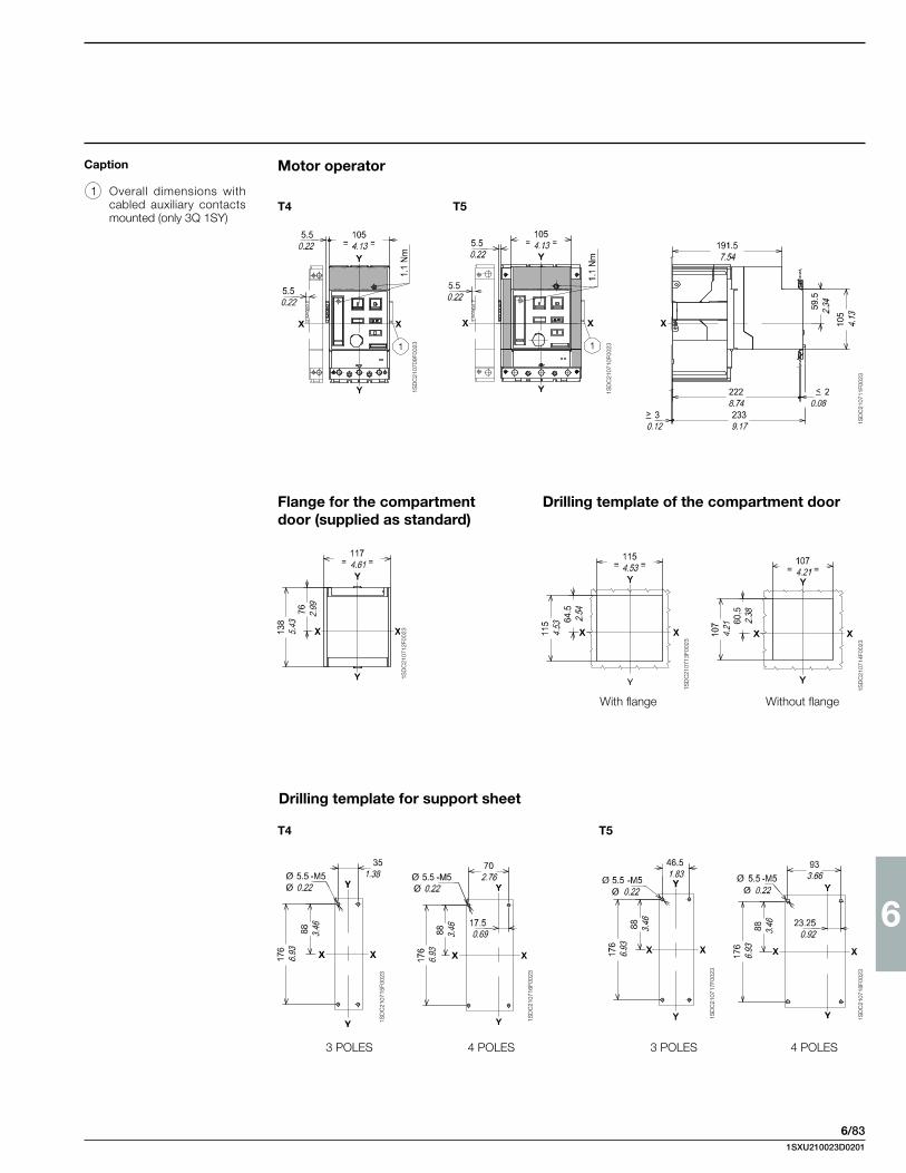
6
6/83
T4 T5
T4 T5
Motor operatorCaption
1 Overall dimensions with cabled auxiliary contacts mounted (only 3Q 1SY)
Flange for the compartment door (supplied as standard)
Drilling template of the compartment door
With flange Without flange
Drilling template for support sheet
1SD
C21
0709
F002
3
1SD
C21
0710
F002
3
1SD
C21
0711
F002
3
1SD
C21
0712
F002
3
1SD
C21
0713
F002
3
1SD
C21
0714
F002
3
1SD
C21
0715
F002
3
1SD
C21
0716
F002
3
1SD
C21
0717
F002
3
1SD
C21
0718
F002
3
3 POLES 4 POLES 3 POLES 4 POLES
1SXU210023D0201

6
6/84
A B C
T1-T2 35 70 17.5
1.38 2.76 0.69
T3 46.5 93 23.25
1.83 3.66 0.92
T4 T5
1SD
C21
0719
F002
3
1SD
C21
0720
F002
3
1SD
C21
0722
F002
3
1SD
C21
0725
F002
3
1SD
C21
0726
F002
3
1SD
C21
0727
F002
3
Front for lever operating mechanismCaption
1 Front for lever operating mechanism
2 Lock for the compartment door (supplied on request)
Flange for the compartment door (supplied as standard)
Drilling template for the compartment door
Drilling template for support sheet
3 POLES4 POLES
1SD
C21
0721
F002
3
Det. “A”
1SD
C21
0723
F002
3
1SD
C21
0724
F002
3
With flange Without flange
For drilling see detail “A” Det. “A”
Overall dimensionsAccessories for Tmax T4 - T5
1SXU210023D0201

6
6/85
Caption
1 Interlocking mechanism
2 Circuit breaker coupling plate
Caption
1 Drilling template for all ver-sions with rear terminals
1SD
C21
0728
F002
31S
DC
2107
29F0
023
1SD
C21
0730
F002
3
Interlock between two circuit breakers placed side by side
Drilling templates for fixing the circuit breaker on the support sheet
Fixed version
1SXU210023D0201

6
6/86
1SD
C21
0731
F002
3
1SD
C21
0732
F002
3
1SD
C21
0733
F002
3
1SD
C21
0734
F002
3
1SD
C21
0735
F002
3
1SD
C21
0736
F002
3
D FE
A B C
Interlock between two circuit breakers placed side by side
Type Circuit breakers
A N° 1 T4 (F-P-W)
N° 1 T4 (F-P-W)
B N° 1 T4 (F-P-W)
N° 1 T5 400 (F-P-W) or T5 600* (F)
C N° 1 T4 (F-P-W)
N° 1 T5 600* (P-W)
D N° 1 T5 400 (F-P-W) or T5 600* (F)
N° 1 T5 400 (F-P-W) or T5 600* (F)
E N° 1 T5 400 (F-P-W) or T5 600* (F)
N° 1 T5 600* (P-W)
F N° 1 T5 600* (P-W)
N° 1 T5 600* (P-W)
Note:(F) Fixed circuit breaker(P) Plug-in circuit breaker(W) Draw out circuit breaker* Please ask ABB for 600 A availability
Overall dimensionsAccessories for Tmax T4 - T5
1SXU210023D0201

6
6/87
Motor operatorDraw out version
1SD
C21
0737
F002
3
1SD
C21
0738
F002
3
1SD
C21
0739
F002
3
1SD
C21
0741
F002
3
1SD
C21
0742
F002
3
T4 T5 (400 A)
Flange for the compartment door (supplied as standard)
Drilling templates for the compartment door and fitting flange
isolating distance
1SXU210023D0201
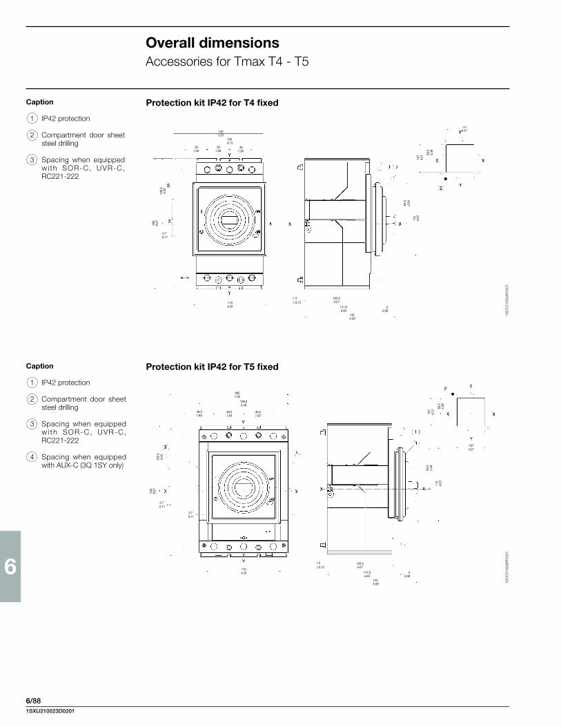
6
6/88
1SD
C21
005A
F000
11S
DC
2106
3BF0
001
115
2.54
4.53
103.54.07
117.54.63
1425.59
≥ 3≥ 0.12
107
4.21
60.5
2.38
2.70.11
102.
54.
03
205
8.07
2.70.11
1867.32
139.55.49
46.51.83
46.51.83
46.51.83
1154.53 2
0.08
64.5
1074.21
1405.51
1054.13
351.38
351.38
351.38
1154.53
2.70.11
102.
54.
03
205
8.07
2.54
115
4.53
103.54.07
117.54.63
1425.59
1074.21
20.08
≥ 3≥ 0.12
107
4.21
60.5
2.38
64.5
Caption
1 IP42 protection
2 Compartment door sheet steel drilling
3 Spacing when equipped wi th SOR-C, UVR-C, RC221-222
Protection kit IP42 for T4 fixed
Protection kit IP42 for T5 fixedCaption
1 IP42 protection
2 Compartment door sheet steel drilling
3 Spacing when equipped w i th SOR-C, UVR-C, RC221-222
4 Spacing when equipped with AUX-C (3Q 1SY only)
Overall dimensionsAccessories for Tmax T4 - T5
1SXU210023D0201

6
6/89
1SD
C21
007B
F000
1
1SD
C21
009B
F000
1
1SD
C21
010B
F000
1
1SD
C21
023B
F000
1
Overall dimensionsAccessories for Tmax T6
Fixed version
Caption
1 Transmission unit
2 Rotary handle assembly with door lock device
3 Padlock device for open pos i t ion (max imum 3 padlocks to be provided by the user)
4 IP54 protection (supplied on request)
5 Min…max distance from the front of the door without accessory 4
6 Min…max distance from the front of the door with accessory 4
7 Dimension with AUE con-nector (early making con-tact)
Rotary handle operating mechanism on the compartment door
Drilling of compartment door
Caption
1 Rotary handle operating mechanism on circuit- breaker
2 Padlock device for open position (maximum 3 pad-locks to be provided by the user)
3 Dimension with AUE con-nector (early making con-tact)
4 Compartment door lock
Rotary handle operating mechanism on circuit breaker
Drilling template of the compartment door Flange for the compartment door
Minimum rotation radius for door
fulcrum
Det. “A”
With flange Without flange
5.50.22
5.50.22
5.50.22
2.70.11
2.70.11
42.5
1.67
82 3.23
105.
54.
15
2103.54.07
110..5004.33..19.68
85..5003.35..19.68
250.98
250.98
20.08
20.08
30.12
1SD
C21
006B
F000
1
R 200 min.
41.51.63
1054.13 R 7.87 min.
321.26
83 3.27 50 1.
97
1SD
C21
008B
F000
1
45
R 31.5R 1.24
Ø 5Ø 0.2
41.51.63
42.5
1.67
Ø 50Ø 1.97
103.5
146.5
190 33
≥ 3 140.5 ≤ 2
7.48
5.77
4.07
1.3
5.53≥ 0.12 ≤ 0.08
5.5
2.7
5.5
5.5
140
0.22
0.22
5.510.22
0.11
2.70.11
41.51.63
42.5
1.67
84.5
3.33
140
5.51
3
Ø 4
2
Ø 0
.16
43 14
90
151
148.5
R min. 200
1.69 0.55
5.94 3.
54
5.85
R min. 7.87
96.5
3.8
43 14
85.5
142
142
R min. 200
1.69 0.55
5.59 3.
37
5.59
R min. 7.87
96.5
3.8
152
173 10
0.25
5.98
6.81 3.
95
1SD
C21
011B
F000
1
1SD
C21
012B
F000
1
1SD
C21
013B
F000
1
1SD
C21
014B
F000
1
1SXU210023D0201

6
6/90
1SD
C21
024B
F000
1
70
237
Ø 5.5 - M5 2.76
Ø 0.22 - M5
9.33
118.
54.
66 35
140
237
Ø 5.5 - M5 Ø 0.22 - M5
9.33
118.
54.
66
5.51
1.38
1SD
C21
029B
F000
1
1SD
C21
030B
F000
1
1SD
C21
025B
F000
1
1SD
C21
026B
F000
1
Motor operatorCaption
1 Overall dimensions with cabled auxiliary contacts mounted (only 3Q 1SY)
Flange for the compartment door (supplied as standard)
Drilling template of the compartment door
Drilling template for support sheet
3 POLES 4 POLES
With flange Without flange
140= =5.5 5.5
0.225.51
0.22
1.1 Nm
5.50.22
3 222 2
233
191.5
140
70
7.54
2.76
5.51
8.74
9.17
0.12 0.08
= =152
173 86
.5
5.98
6.81
3.4
= =
151
148.5
R min. 200
5.94
5.85
R min. 7.87
75.7
52.
98
= =
142
142
R min. 200
5.59
5.59
R min. 7.87
71.2
52.
8
1SD
C21
028B
F000
1
1SD
C21
027B
F000
1
Overall dimensionsAccessories for Tmax T6
1SXU210023D0201

6
6/91
1SD
C21
032B
F000
1
1SD
C21
036B
F000
1
70
237
Ø 5.5 - M5 2.76Ø 0.22 - M5
9.33
118.
54.
66 35
140
237
Ø 5.5 - M5 Ø 0.22 - M5
9.33
118.
54.
66
5.51
1.38
1SD
C21
037B
F000
1
1SD
C21
038B
F000
1
Caption
1 Front for lever operating mechanism
2 Lock for the compartment door
Front for lever operating mechanism
Flange for the compartment door (supplied as standard)
Drilling template for the compartment door
Drilling template for support sheet
3 POLES 4 POLES
Det. “A”
Det. “A”
Drilling of details “A”
Fixed version
2.7 140= =0.112.7
0.115.51
1SD
C21
031B
F000
1
103.5
146.5
158
17
14084
.5
6.22
146.5
4.07 0.67
3.33
5.51
≥ 3 140.5 ≤ 25.53≥ 0.12 ≤ 0.08
Ø 4
Ø 0
.16= =
152
173 10
0.25
5.98
6.81 3.
95
1SD
C21
033B
F000
1
43 14
90
151
148.5
R min. 200
1.69 0.55
5.94 3.
54
5.85
R min. 7.87
96.5
3.8
1SD
C21
034B
F000
1
43 14
85.5
142
142
R min. 200
1.69 0.55
5.59 3.
37
5.59
R min. 7.8796
.53.
81S
DC
2103
5BF0
001
1SXU210023D0201

6
6/92
1SD
C21
040B
F000
1
1SD
C21
041B
F000
1
1SD
C21
042B
F000
1
1SD
C21
039B
F000
1
Draw out version Motor operator
Flange for the compartment door (supplied as standard)
Drilling templates for the compartment door and fitting flange
241
281.5
27.5 isolating distance
70
5.51
37
1.08
9.49
1.46
2.76
0.22
≥ 3 ≤ 2≥ 0.12 ≤ 0.08
11.08
27210.71
1405.511.1 Nm
75.25
210
173 86
.25
6.81
3.4
2.96
8.27
150
=
=148.5
32.5
122
18
3275.2
5
5.9 2.
96
1.28
1.26
0.71
4.8
R min. 200R min. 7.87
5.85
Overall dimensionsAccessories for Tmax T6
1SXU210023D0201

6
6/93
4
2
1SD
C21
0L36
F000
1
Det. “A”
1SD
C21
045B
F000
1
1SD
C21
046B
F000
1
1SD
C21
048B
F000
1
Caption
1 Padlock device for open position (maximum 3 pad-locks to be provided by the user)
2 Lock for compartment door
3 Dimension with AUE con-nector (early making con-tact)
4 Interlocking mechanism
5 Circuit breaker coupling plate
6 Drilling template for all ver-sions of terminals
Rotary handle operating mechanism on the circuit breakers
Flange for the compartment door Drilling template for compartment door and fitting flange
Mechanical interlock
190.5
240
84.5
140
33
1
27.5 isolating distance1.08
≥ 3 ≤ 2≥ 0.12 ≤ 0.087.5
9.45 1.3
3.33
5.51
140
3
5.51
1SD
C21
043B
F000
1
1SD
C21
044B
F000
1
75.25
210
173 10
0.25
6.81 3.
95
8.27
2.96
Drilling for detail “A”
18.5
89.5
150
= =148.5
122
18
32
5.9 1.26
0.71
4.8R min. 200R min. 7.87
5.85
43 141.69 0.55
96.5
3.8
3.52
0.73
5
4
67326.5
702.76
702.76
702.76
702.76
702.76
702.76
1204.72
1305.12
2007.87
390
15.3
565 2.56
103.
54.
07
295
11.6
1+2
7.5
isol
atin
g di
stan
ce+1
.08
1SD
C21
047B
F000
1
6
335
13.1
9
104
4.09
104
4.09
53821.18
360
14.1
7
Ø 9Ø 0.35
1SXU210023D0201

6
6/94
1SD
C21
052B
F000
1
1SD
C21
050B
F000
1
1SD
C21
051B
F000
1
1SD
C21
050B
F000
1
1SD
C21
052B
F000
1
Overall dimensionsAccessories for Tmax T7
Fixed circuit breaker Rotary handle operating mechanism on the circuit breaker
Caption
1 Rotary handle operat-ing mechanism for circuit breaker
2 Compartment door inter-lock
3 Flange for the compartment door
4 Flange fixing screws
6 Support sheet drilling tem-plate
7 Key lock (optional)
8 Tightening torque: 2.5 Nm
9 Compartment door with flange sheet drilling
10 Compartment door sheet drilling for front 206 x 204
11 Terminal for auxiliary con-tacts
12 Reduced flange of the rotary handle for the compartment door (optional)
13 Compartment door sheet drilling for rotary handle
14 Compartment door sheet drilling without the rotary handle flange
Flange for the compartment door (supplied as standard)
Drilling templates of the compartment door
Drilling templates for support sheet
With flange Without flange
A 125...141 147
4.92...5.55 5.79
III IV
C 70 140
2.76 5.51
7070
28011.02
2108.27
103.64.08
7070
7070
60.24
134
5.28 14
7.5
5.81
268
10.5
515
46.
06 152
5.98
189.
57.
46
1907.482068.11
26810.55
304
11.9
715
25.
98
245
9.64
122.
54.
82 351.38
Ø 5.5 - M5Ø 0.22
1254.92
973.82
43.51.71
331.30
18.7
50.
74
105
4.13
204
8.03
102
4.01
1847.24
20.08 2
0.08
20.08
2037.99
138
5.43
35.2
51.
39
263
10.3
5
151
5.94
144.
55.
6914
4.5
5.69
103
4.05
206
8.11
96.7
53.
8111
64.
57
24.2
50.
95
2419.492268.9
Ø 4 n°7 HOLESØ 0.16
R min = 200R min = 7.87
2088.19
R min = 200R min = 7.87
R min = 200R min = 7.87 R min = 200
R min = 7.87
2017.91
22.50.88
140.55
Ø 4
Ø 0
.16
22.50.88
140.55
1927.56
107
4.21
19.7
50.
78
7070
28011.02
2108.27
103.64.08
7070
7070
60.24
134
5.28 14
7.5
5.81
268
10.5
515
46.
06 152
5.98
189.
57.
46
1907.482068.11
26810.55
304
11.9
715
25.
98
245
9.64
122.
54.
82 351.38
Ø 5.5 - M5Ø 0.22
7070
28011.02
2108.27
103.64.08
7070
7070
60.24
134
5.28 14
7.5
5.81
268
10.5
515
46.
06 152
5.98
189.
57.
46
1907.482068.11
26810.55
304
11.9
715
25.
98
245
9.64
122.
54.
82 351.38
Ø 5.5 - M5Ø 0.22
2037.99
138
5.43
35.2
51.
39
263
10.3
5
151
5.94
144.
55.
6914
4.5
5.69
103
4.05
206
8.11
96.7
53.
8111
64.
57
24.2
50.
95
2419.492268.9
Ø 4 n°7 HOLESØ 0.16
R min = 200R min = 7.87
2088.19
R min = 200R min = 7.87
R min = 200R min = 7.87 R min = 200
R min = 7.87
2017.91
22.50.88
140.55
Ø 4
Ø 0
.16
22.50.88
140.55
1927.56
107
4.21
19.7
50.
78
1SD
C21
050B
F000
1
1SXU210023D0201

6
6/95
1254.92
973.82
30.12
120..4874.72..19.17
95..4873.74..19.17
26.81.05
20.08
20.7
50.
82
39.5
1.55
105.
54.
15
150.59
82..4743.23..18.66
107..4744.21..18.66
62.52.46
R min = 200R min = 7.87
1054.13
321.26
33 1.3
50 1.97
20.7
50.
82
Ø 63Ø 2.5
Ø 50Ø 1.97
Ø 5Ø 0.2
62.52.46
1SD
C21
053B
F000
1
Caption
1 Transmission mechanism for rotary handle operating mechanism
2 Grip with key lock in open position (max n° 3 padlocks _7 mm not included in the supply)
3 Drilling template for com-partment door
4 Tightening torque 2.5 Nm
5 Accessory for IP54 degree of protection (available on request)
6 Min…max distance from the front of the door
7 Min…max distance from the front of the door (with accessory with IP54 degree of protection)
Rotary handle operating mechanism on the compartment door
1SXU210023D0201
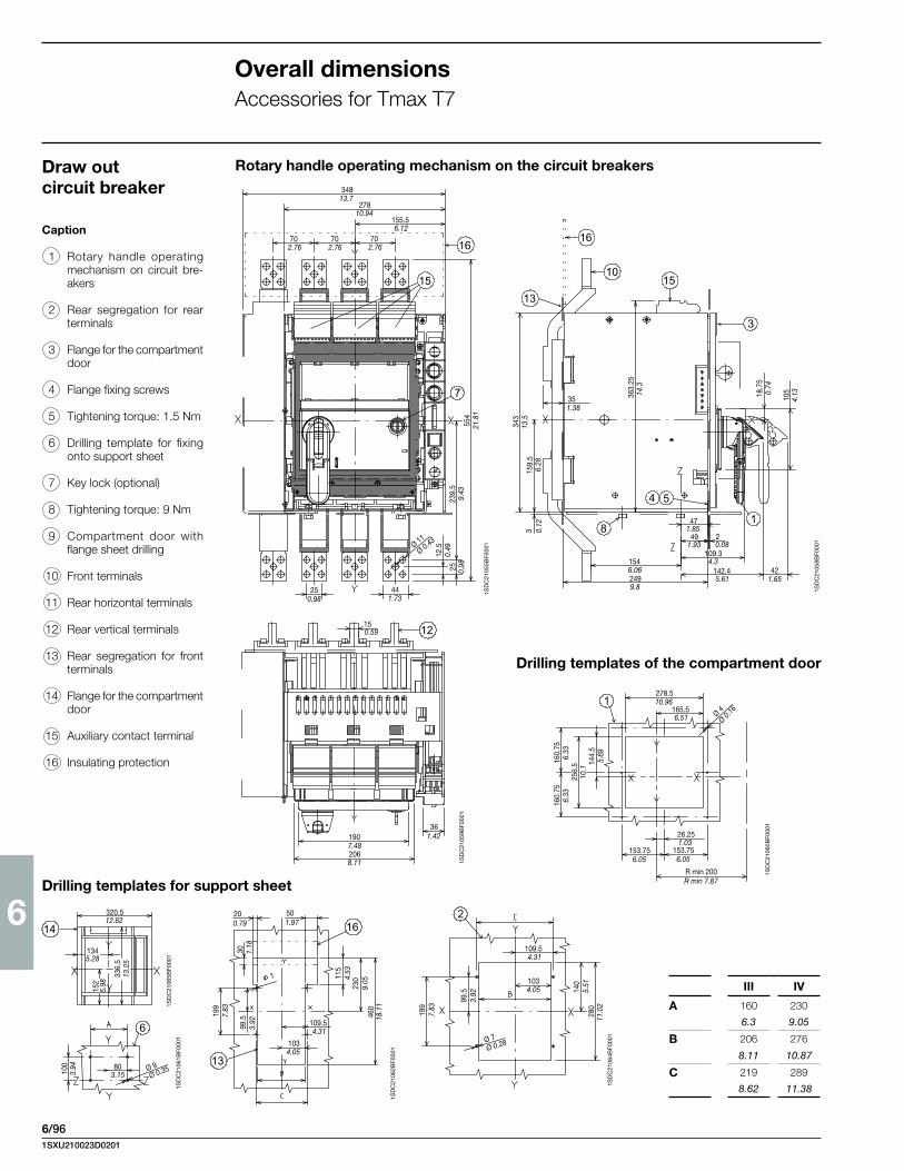
6
6/96
III IV
A 160 230
6.3 9.05
B 206 276
8.11 10.87
C 219 289
8.62 11.38
1SD
C21
059B
F000
1
1SD
C21
060B
F000
1
1SD
C21
062B
F000
1
1SD
C21
065B
F000
1
1SD
C21
064B
F000
1
1SD
C21
055B
F000
1
1SD
C21
058B
F000
1
Draw out circuit breaker
Drilling templates for support sheet
Drilling templates of the compartment door
Caption
1 Rotary handle operating mechanism on circuit bre-akers
2 Rear segregation for rear terminals
3 Flange for the compartment door
4 Flange fixing screws
5 Tightening torque: 1.5 Nm
6 Drilling template for fixing onto support sheet
7 Key lock (optional)
8 Tightening torque: 9 Nm
9 Compartment door with flange sheet drilling
10 Front terminals
11 Rear horizontal terminals
12 Rear vertical terminals
13 Rear segregation for front terminals
14 Flange for the compartment door
15 Auxiliary contact terminal
16 Insulating protection
Rotary handle operating mechanism on the circuit breakers
16
15
7
34813.7
27810.94
155.56.12
702.76
702.76
702.76
250.98
441.73
12.5
0.49
25 0.98
239.
59.
43
Ø 11
Ø 0.43
554
21.8
1
10
13
15
16
3
4 5
81
18.7
50.
74
105
4.1336
3.25
14.3
343
13.5
159.
56.
283 0.
12
1546.062499.8
471.85
491.93
20.08
109.34.3
142.45.61
421.65
351.38
12150.59
361907.482068.11
1.42
1278.510.96
165.56.51
160.
756.
3316
0.75
6.33
256.
510
.114
4.5
5.69
26.251.03
153.756.05
153.756.05
R min 200R min 7.87
Ø 4
Ø 0.16
6
803.1510
03.
94 Ø 9Ø 0.35
16
13
200.79
501.97
1034.05
109.54.31
199
7.83
99.5
3.92
30 1.18
115
4.53
230
9.05
460
18.1
1
14
336.
513
.25
152
5.98
1345.28
320.512.62
2
1034.05
109.54.31
199
7.83
99.5
3.92
Ø 7Ø 0.28
140
5.51
280
11.0
2
1SD
C21
061B
F000
1
Overall dimensionsAccessories for Tmax T7
1SXU210023D0201

6
6/97
Mechanical interlock for fixed circuit breakersCaption
3 Mechanical vertical interlock for fixed circuit breakers
4 Mechanical horizontal in-terlock for fixed circuit bre-akers
5 Sheet drilling for wire pas-sage of the mechanical interlock
803.15
1525.98
R 70 MINR 2.76 MIN
803.15
1525.98
R 70 MINR 2.76 MIN
1000
MA
X39
.37
MA
X
1756.89
153.56.04
301.18
153.56.04
301.18
R 70 MINR 2.76 MIN
1000 MAX39.37 MAX
1756.89
R 70 MINR 2.76 MIN
R 70 MINR 2.76 MIN
1000 MAX39.37 MAX
R 70 MINR 2.76 MIN
146.55.77
146.55.77
1254.92
301.18
1254.92
301.18
R 70 MINR 2.76 MIN
R 70 MINR 2.76 MIN
1000
MA
X39
.37
MA
X
702.76
501.97
702.76
501.97
1SD
C21
066B
F000
1
1SXU210023D0201
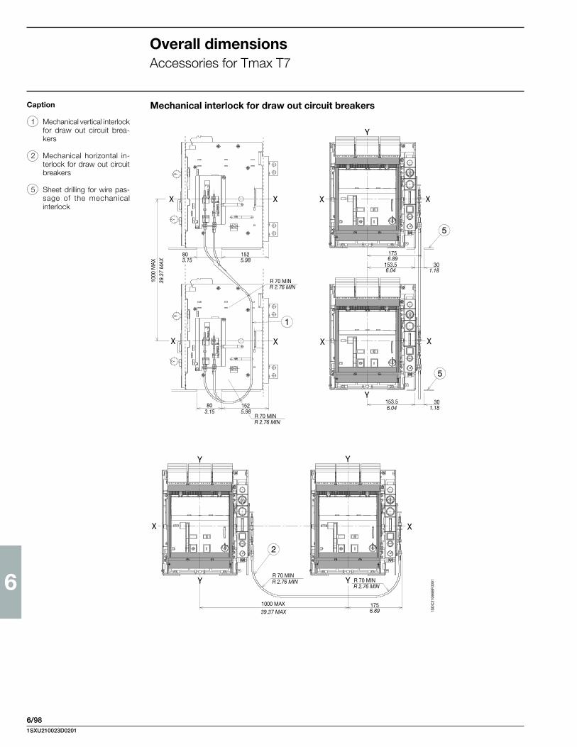
6
6/98
Mechanical interlock for draw out circuit breakersCaption
1 Mechanical vertical interlock for draw out circuit brea-kers
2 Mechanical horizontal in-terlock for draw out circuit breakers
5 Sheet drilling for wire pas-sage of the mechanical interlock
803.15
1525.98
R 70 MINR 2.76 MIN
803.15
1525.98
R 70 MINR 2.76 MIN
1000
MA
X39
.37
MA
X
1756.89
153.56.04
301.18
153.56.04
301.18
R 70 MINR 2.76 MIN
1000 MAX39.37 MAX
1756.89
R 70 MINR 2.76 MIN
R 70 MINR 2.76 MIN
1000 MAX39.37 MAX
R 70 MINR 2.76 MIN
146.55.77
146.55.77
1254.92
301.18
1254.92
301.18
R 70 MINR 2.76 MIN
R 70 MINR 2.76 MIN
1000
MA
X39
.37
MA
X
702.76
501.97
702.76
501.97
1SD
C21
066B
F000
1
Overall dimensionsAccessories for Tmax T7
1SXU210023D0201
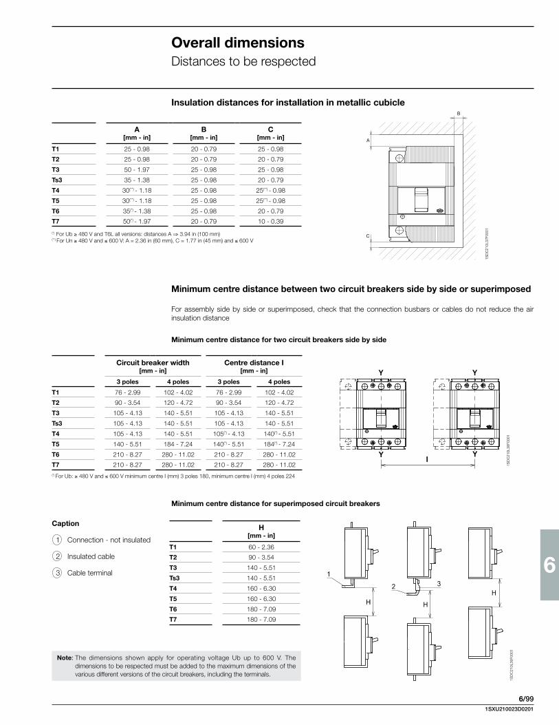
6
6/99
1SD
C21
0L37
F000
1
1SD
C21
0L38
F000
11S
DC
210L
39F0
001
H [mm - in]
T1 60 - 2.36
T2 90 - 3.54
T3 140 - 5.51
Ts3 140 - 5.51
T4 160 - 6.30
T5 160 - 6.30
T6 180 - 7.09
T7 180 - 7.09
Overall dimensionsDistances to be respected
Caption
1 Connection - not insulated
2 Insulated cable
3 Cable terminal
Insulation distances for installation in metallic cubicle
Minimum centre distance between two circuit breakers side by side or superimposed
For assembly side by side or superimposed, check that the connection busbars or cables do not reduce the air insulation distance
Minimum centre distance for superimposed circuit breakers
Minimum centre distance for two circuit breakers side by side
Note: The dimensions shown apply for operating voltage Ub up to 600 V. The dimensions to be respected must be added to the maximum dimensions of the various different versions of the circuit breakers, including the terminals.
A[mm - in]
B[mm - in]
C[mm - in]
T1 25 - 0.98 20 - 0.79 25 - 0.98
T2 25 - 0.98 20 - 0.79 20 - 0.79
T3 50 - 1.97 25 - 0.98 25 - 0.98
Ts3 35 - 1.38 25 - 0.98 20 - 0.79
T4 30(**) - 1.18 25 - 0.98 25(**) - 0.98
T5 30(**) - 1.18 25 - 0.98 25(**) - 0.98
T6 35(*) - 1.38 25 - 0.98 20 - 0.79
T7 50(*) - 1.97 20 - 0.79 10 - 0.39
(*) For Ub ≥ 480 V and T6L all versions: distances A ⇒ 3.94 in (100 mm)(**) For Un ≥ 480 V and ≤ 600 V: A = 2.36 in (60 mm), C = 1.77 in (45 mm) and ≤ 600 V
Circuit breaker width [mm - in]
Centre distance I [mm - in]
3 poles 4 poles 3 poles 4 poles
T1 76 - 2.99 102 - 4.02 76 - 2.99 102 - 4.02
T2 90 - 3.54 120 - 4.72 90 - 3.54 120 - 4.72
T3 105 - 4.13 140 - 5.51 105 - 4.13 140 - 5.51
Ts3 105 - 4.13 140 - 5.51 105 - 4.13 140 - 5.51
T4 105 - 4.13 140 - 5.51 105(*) - 4.13 140(*) - 5.51
T5 140 - 5.51 184 - 7.24 140(*) - 5.51 184(*) - 7.24
T6 210 - 8.27 280 - 11.02 210 - 8.27 280 - 11.02
T7 210 - 8.27 280 - 11.02 210 - 8.27 280 - 11.02(*) For Ub: ≥ 480 V and ≤ 600 V minimum centre I (mm) 3 poles 180, minimum centre I (mm) 4 poles 224
1SXU210023D0201


ABB Inc.
Low Voltage Control Products
16250 W. Glendale Drive New Berlin, WI 53151
Phone: 888-385-1221 Fax: 800-726-1441
USA Technical Help: 888-385-1221, Option 4 7:30AM to 5:30PM, CST, Monday - Friday
Web: www.abb.us/lowvoltage
Contact us
Due to possible developments of standards as well as of materials, the characteristics and dimensions specifi ed in the present catalogue may only be considered binding after confi rmation by ABB.
1S
XU
21
00
23
D0
20
1 -
11
/20
11


