

69

70
1000
893
112
28
3676
112 12
28
TEK 28 profile
TEC
HN
ICA
L D
ATA
SH
EET
Made in: Aluminium
*(it is calculated in the dual hypothesis of σ perm. = 6,5 kN/cm2 and ƒ perm. = i/200)
The contents of this calculation table are to be considered approximate and purely indicative. The structural calculation is the task of the designer and/or user in each single case that also has to determine the application design specifications for the roofing in question
PERMITTED UNIFORM LOAD [kg/m2] ON 4 SUPPORTS
i [m] 1.00 1.20 1.40 1.60 1.80s [mm] σperm ƒperm σperm ƒperm σperm ƒperm σperm ƒperm σperm ƒperm
0,6 452 414 314 240 231 151 177 101 139 71
0,7 527 483 366 280 269 176 206 118 163 83
0,8 603 553 419 320 308 201 235 135 186 95
1,0 754 691 523 400 385 252 294 169 233 118
ALUMINIUM TECHNICAL SPECIFICATIONS (referring only to the metal sheet)
s p J W EJ M max Symbolss = sheet thicknessp = unit weightJ = moment of inertiaW = modulus of bending resistanceEJ = bending stiffnessM max = permitted bending moment(σ perm.= 6,5 kN/cm2)i = centre distance between supportsσ perm. = unit safety load ƒ perm. = maximum permitted straining
[mm] [kg/m2] [cm4/m] [cm3/m] [kN cm2/m] [kN cm/m]
0,6 2,05 9,22 6,83 63.536 44,39
0,7 2,39 10,76 7,97 74.136 51,81
0,8 2,73 12,30 9,11 84.747 59,21
1,0 3,42 15,38 11,39 105.968 74,03

71
1000
893
112
28
3676
112 12
28
TEK 28 profile
Made in: Steel
TEC
HN
ICA
L D
ATA
SH
EET
*(it is calculated in the dual hypothesis of σ perm. = 1400 kg/cm2 = 13,73 kN/cm2 and ƒ perm. = i/200)The contents of this calculation table are to be considered approximate and purely indicative. The structural calculation is the task of the designer and/or user in each single case that also has to determine the application design specifications for the roofing in question
PERMITTED UNIFORM LOAD [kg/m2] ON 4 SUPPORTS
i [m] 1.00 1.25 1.50 1.75 2.00 2.25 2.50 2.75 3.00
s [mm] σperm ƒperm σperm ƒperm σperm ƒperm σperm ƒperm σperm ƒperm σperm ƒperm σperm ƒperm σperm ƒperm σperm ƒperm
0,5 501 1.032 321 528 223 306 164 193 126 129 99 91 80 66 66 50 56 380,6 678 1.239 434 634 301 367 221 231 169 155 134 109 108 79 90 60 75 460,7 878 1.446 562 740 390 428 287 270 219 181 173 127 140 93 116 70 98 540,8 1.103 1.653 706 846 490 490 360 308 276 207 218 145 177 106 146 79 123 611,0 1.567 2.067 1.003 1.058 696 612 512 386 392 258 309 181 251 132 207 99 174 76
STEEL TECHNICAL SPECIFICATIONS (referring only to the metal sheet)
s p J W EJ M max Symbolss = sheet thicknessp = unit weightJ = moment of inertiaW = modulus of bending resistanceEJ = bending stiffnessM max = permitted bending moment(σ perm.= 13,73 kN/cm2)i = centre distance between supportsσ perm. = unit safety load ƒ perm. = maximum permitted straining
[mm] [kg/m2] [cm4/m] [cm3/m] [kN cm2/m] [kN cm/m]
0,5 4,88 7,68 3,58 158.208 49,15
0,6 5,85 9,22 4,84 189.932 66,45
0,7 6,83 10,76 6,27 221.656 86,09
0,8 7,81 12,30 7,88 253.380 108,19
1,0 9,76 15,38 11,19 316.828 153,64
72
1000
893
112
28
3676
112 12
28
1000
TEK 28 profile
TEC
HN
ICA
L D
ATA
SH
EET
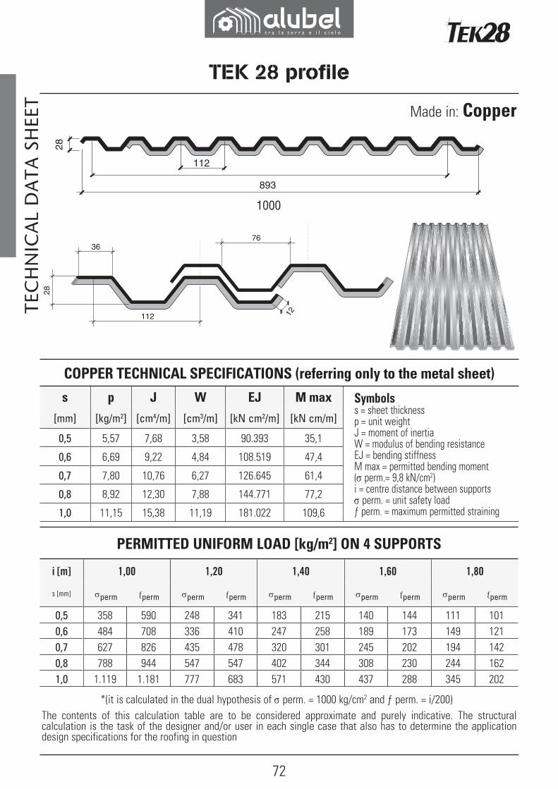
Made in: Copper
*(it is calculated in the dual hypothesis of σ perm. = 1000 kg/cm2 and ƒ perm. = i/200)The contents of this calculation table are to be considered approximate and purely indicative. The structural calculation is the task of the designer and/or user in each single case that also has to determine the application design specifications for the roofing in question
COPPER TECHNICAL SPECIFICATIONS (referring only to the metal sheet)
s p J W EJ M max Symbolss = sheet thicknessp = unit weightJ = moment of inertiaW = modulus of bending resistanceEJ = bending stiffnessM max = permitted bending moment(σ perm.= 9,8 kN/cm2)i = centre distance between supportsσ perm. = unit safety load ƒ perm. = maximum permitted straining
[mm] [kg/m2] [cm4/m] [cm3/m] [kN cm2/m] [kN cm/m]
0,5 5,57 7,68 3,58 90.393 35,1
0,6 6,69 9,22 4,84 108.519 47,4
0,7 7,80 10,76 6,27 126.645 61,4
0,8 8,92 12,30 7,88 144.771 77,2
1,0 11,15 15,38 11,19 181.022 109,6
PERMITTED UNIFORM LOAD [kg/m2] ON 4 SUPPORTS
i [m] 1,00 1,20 1,40 1,60 1,80
s [mm] σperm ƒperm σperm ƒperm σperm ƒperm σperm ƒperm σperm ƒperm
0,5 358 590 248 341 183 215 140 144 111 1010,6 484 708 336 410 247 258 189 173 149 1210,7 627 826 435 478 320 301 245 202 194 1420,8 788 944 547 547 402 344 308 230 244 1621,0 1.119 1.181 777 683 571 430 437 288 345 202
73
R5000
TEK 28 profile
R5000
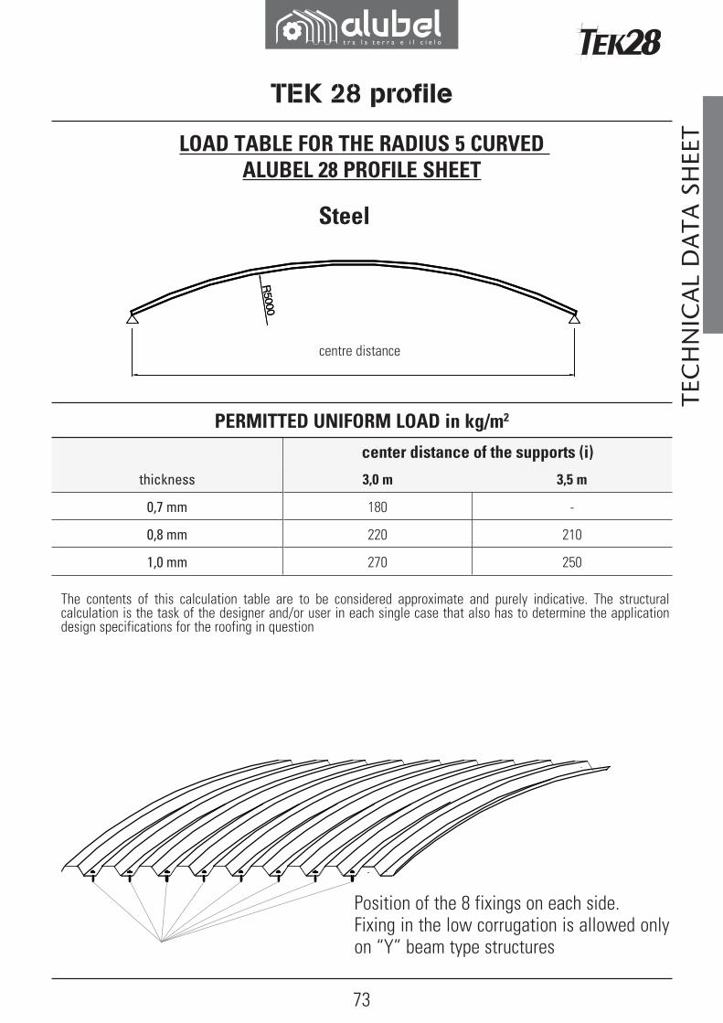
The contents of this calculation table are to be considered approximate and purely indicative. The structural calculation is the task of the designer and/or user in each single case that also has to determine the application design specifications for the roofing in question
Position of the 8 fixings on each side. Fixing in the low corrugation is allowed only on “Y” beam type structures
Steel
TEC
HN
ICA
L D
ATA
SH
EET
centre distance
PERMITTED UNIFORM LOAD in kg/m2
center distance of the supports (i)
thickness 3,0 m 3,5 m
0,7 mm 180 -
0,8 mm 220 210
1,0 mm 270 250
LOAD TABLE FOR THE RADIUS 5 CURVED ALUBEL 28 PROFILE SHEET

74
R3000
1 2 3 4
TEC
HN
ICA
L D
ATA
SH
EET
Aluminium
Position of the 4 fixings on each side. Fixing in the low corrugation is allowed only on “Y” beam type structures
Uniformly distributed load, expressed in kg/m2
σ perm. = 6,5 kN/cm2
number of fixings on each side (to be put on the low part of the corrugation) with 6,3 mm ø steel fixings necessary to support the permitted load (predefined as 4 fixings on each side).The treadable surface has been verified as per Italian Ministerial Decree 16/01/1996 par. 5.2.
The contents of this calculation table are to be considered approximate and purely indicative. The structural calculation is the task of the designer and/or user in each single case that also has to determine the application design specifications for the roofing in question.
centre distance
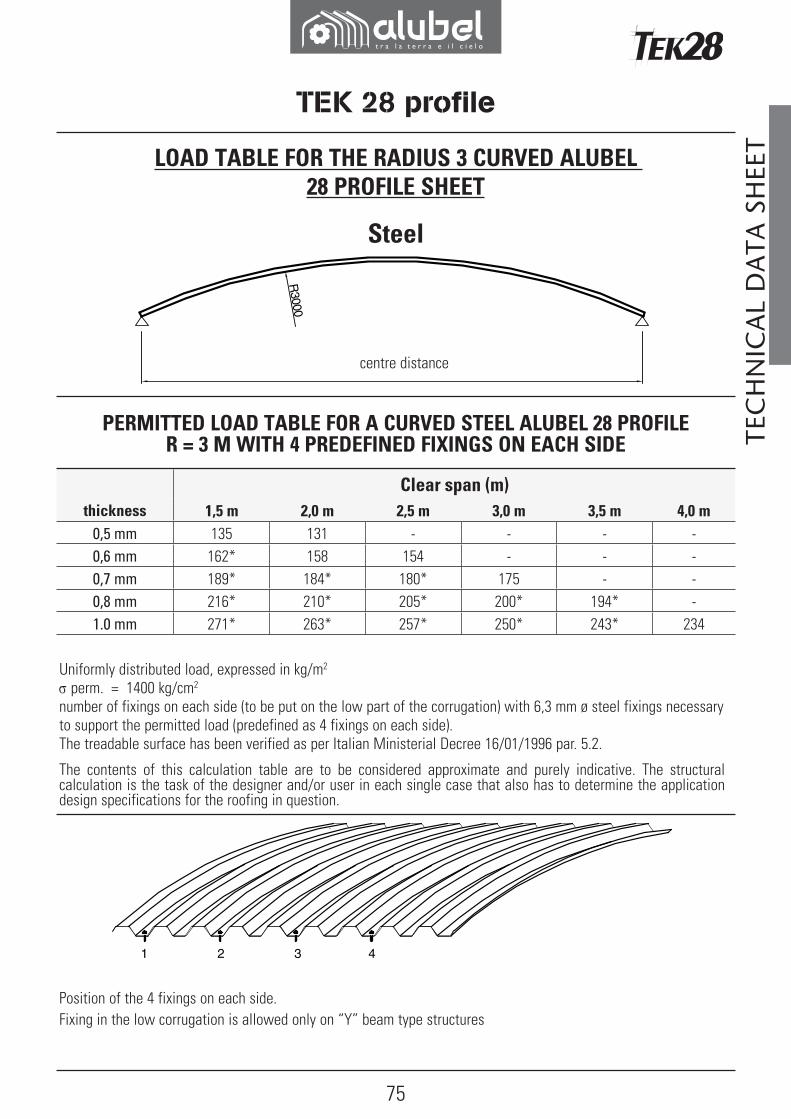
LOAD TABLE FOR RADIUS 3 CURVED ALUBEL 28 PROFILE SHEET
TEK 28 profile
PERMITTED LOAD TABLE FOR A CURVED ALUMINIUM ALUBEL 28 PROFILE R = 3 M WITH 4 PREDEFINED FIXINGS ON EACH SIDE
Clear span (m)
thickness 1,5 m 2,0 m 2,5 m 3,0 m
0,7 mm 106 - - -
0,8 mm 120* 113 - -
1,0 mm 153* 150* 143 140
75
R3000
1 2 3 4
TEC
HN
ICA
L D
ATA
SH
EET LOAD TABLE FOR THE RADIUS 3 CURVED ALUBEL
28 PROFILE SHEET
Uniformly distributed load, expressed in kg/m2
σ perm. = 1400 kg/cm2
number of fixings on each side (to be put on the low part of the corrugation) with 6,3 mm ø steel fixings necessary to support the permitted load (predefined as 4 fixings on each side).The treadable surface has been verified as per Italian Ministerial Decree 16/01/1996 par. 5.2.
The contents of this calculation table are to be considered approximate and purely indicative. The structural calculation is the task of the designer and/or user in each single case that also has to determine the application design specifications for the roofing in question.
Position of the 4 fixings on each side. Fixing in the low corrugation is allowed only on “Y” beam type structures
Steel
centre distance
TEK 28 profile
PERMITTED LOAD TABLE FOR A CURVED STEEL ALUBEL 28 PROFILE R = 3 M WITH 4 PREDEFINED FIXINGS ON EACH SIDE
Clear span (m)thickness 1,5 m 2,0 m 2,5 m 3,0 m 3,5 m 4,0 m
0,5 mm 135 131 - - - -0,6 mm 162* 158 154 - - -0,7 mm 189* 184* 180* 175 - -0,8 mm 216* 210* 205* 200* 194* -1.0 mm 271* 263* 257* 250* 243* 234
76
R3000
1 2 3 4
TEK 28 profile
TEC
HN
ICA
L D
ATA
SH
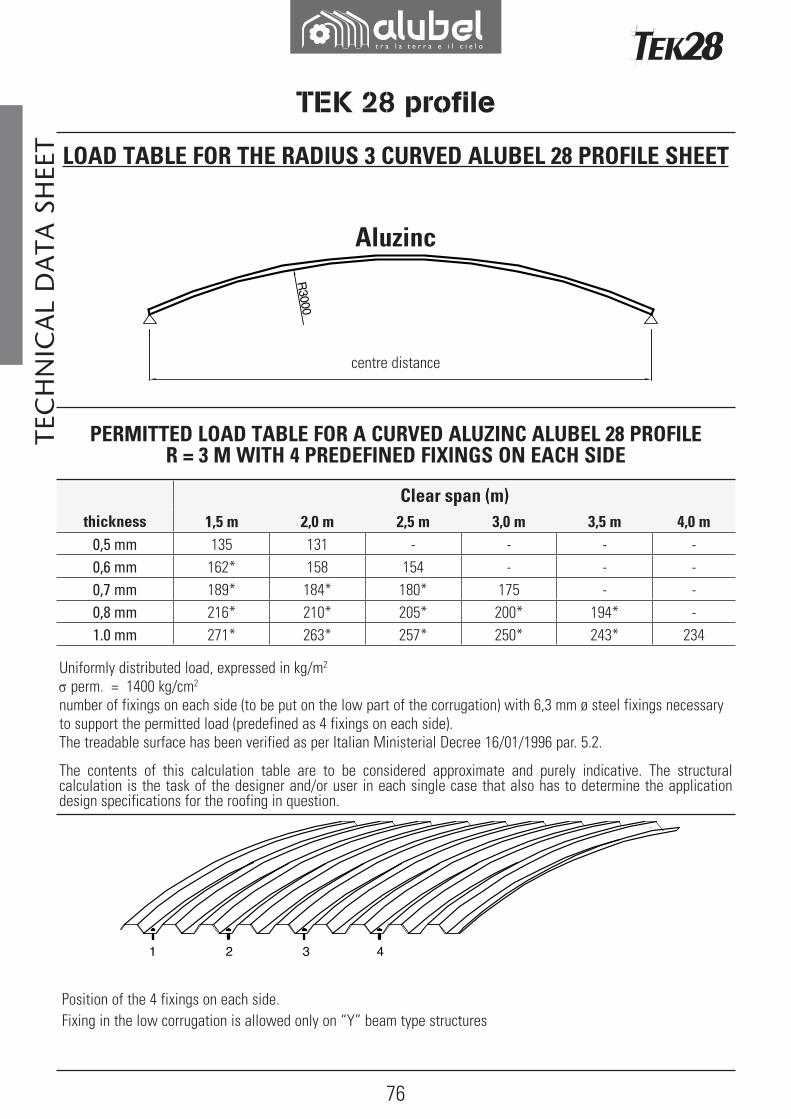
EET LOAD TABLE FOR THE RADIUS 3 CURVED ALUBEL 28 PROFILE SHEET
Aluzinc
Uniformly distributed load, expressed in kg/m2
σ perm. = 1400 kg/cm2
number of fixings on each side (to be put on the low part of the corrugation) with 6,3 mm ø steel fixings necessary to support the permitted load (predefined as 4 fixings on each side).The treadable surface has been verified as per Italian Ministerial Decree 16/01/1996 par. 5.2.
The contents of this calculation table are to be considered approximate and purely indicative. The structural calculation is the task of the designer and/or user in each single case that also has to determine the application design specifications for the roofing in question.
Position of the 4 fixings on each side. Fixing in the low corrugation is allowed only on “Y” beam type structures
centre distance
PERMITTED LOAD TABLE FOR A CURVED ALUZINC ALUBEL 28 PROFILE R = 3 M WITH 4 PREDEFINED FIXINGS ON EACH SIDE
Clear span (m)thickness 1,5 m 2,0 m 2,5 m 3,0 m 3,5 m 4,0 m
0,5 mm 135 131 - - - -0,6 mm 162* 158 154 - - -0,7 mm 189* 184* 180* 175 - -0,8 mm 216* 210* 205* 200* 194* -1.0 mm 271* 263* 257* 250* 243* 234

77
SBA
Ri
50
150
TEK 28 profile
UNIFORM CURVATURE BY NOTCHING
SHEE
T TO
OLI
NG
UNIFORM CURVATURE BY NOTCHING
S max sheet length
Ri alluminium other materials
from 3 to 4 m max 5 m max 4 m
da 4 a 6 m max 6 m max 6 m

78
B
A
S
a
RiP
TEK 28 profile
PARTIAL CURVATURE BY NOTCHING
SHEE
T TO
OLI
NG
SymbolsA initial section min 50 max 2000 mm
B end section min 50 max 2000 mm
S curve development min 100 mm
A+B+S total development (aluminium) max 5000* mm
A+B+S total development (other mater.) max 5000* mm
Ri inside radius min 400 mm
P impression distance min 35 mm
a defl ection angle(aluminium) min 1° max 3°
a angolo di defl essione (other materials) min 1° max 2° (steel)
* total variable development based on the inside radius

79
P
S
BAmax 4000 max 4000
TEK 28 profile
SHEE
T TO
OLI
NGNOTCHING IN THE MIDDLE
Sheet curved only in the centre to form the ridge and the joining of two pitches (achieved by means of a set of impressions in the middle of the sheet).The length of the straight segments A and B varies from a minimum of 50 mm to a maximum of 4000 mm.
S max sheet length
P aluminium other materials
from 6 to 12% max 10 m max 6 m
from 12 to 15% max 10 m max 6 m
from 15 to 20% max 8 m max 6 m
from 20 to 25% max 8 m max 4 m
80
Y
CBA
Y
CBA
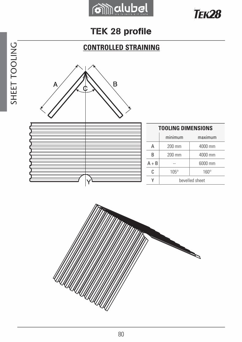
CONTROLLED STRAINING
SHEE
T TO
OLI
NG
TEK 28 profile
TOOLING DIMENSIONS
minimum maximum
A 200 mm 4000 mm
B 200 mm 4000 mm
A + B -- 6000 mm
C 105° 160°
Y bevelled sheet
81
T
L
Laying direction Laying direction
TEK 28 profile
SHEE
T TO
OLI
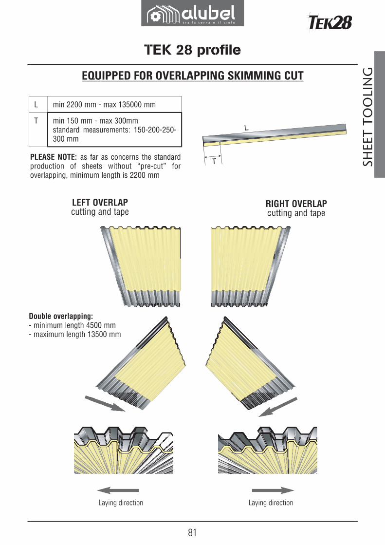
NGEQUIPPED FOR OVERLAPPING SKIMMING CUT
Double overlapping:- minimum length 4500 mm- maximum length 13500 mm
LEFT OVERLAPcutting and tape
RIGHT OVERLAPcutting and tape
PLEASE NOTE: as far as concerns the standard production of sheets without “pre-cut” for overlapping, minimum length is 2200 mm
L min 2200 mm - max 135000 mm
T min 150 mm - max 300mmstandard measurements: 150-200-250-300 mm
82
100
200 200
280 280
36
246
280
250
TEK 28 profile
AC
CES
SORI
ES
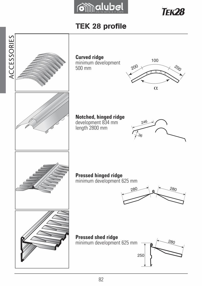
Pressed hinged ridgeminimum development 625 mm
Notched, hinged ridgedevelopment 834 mmlength 2800 mm
Curved ridgeminimum development 500 mm
Pressed shed ridgeminimum development 625 mm
83
L2
L1
850
218150
33120
15
105
280120
67
33
TEK 28 profile
AC
CES
SORI
ES
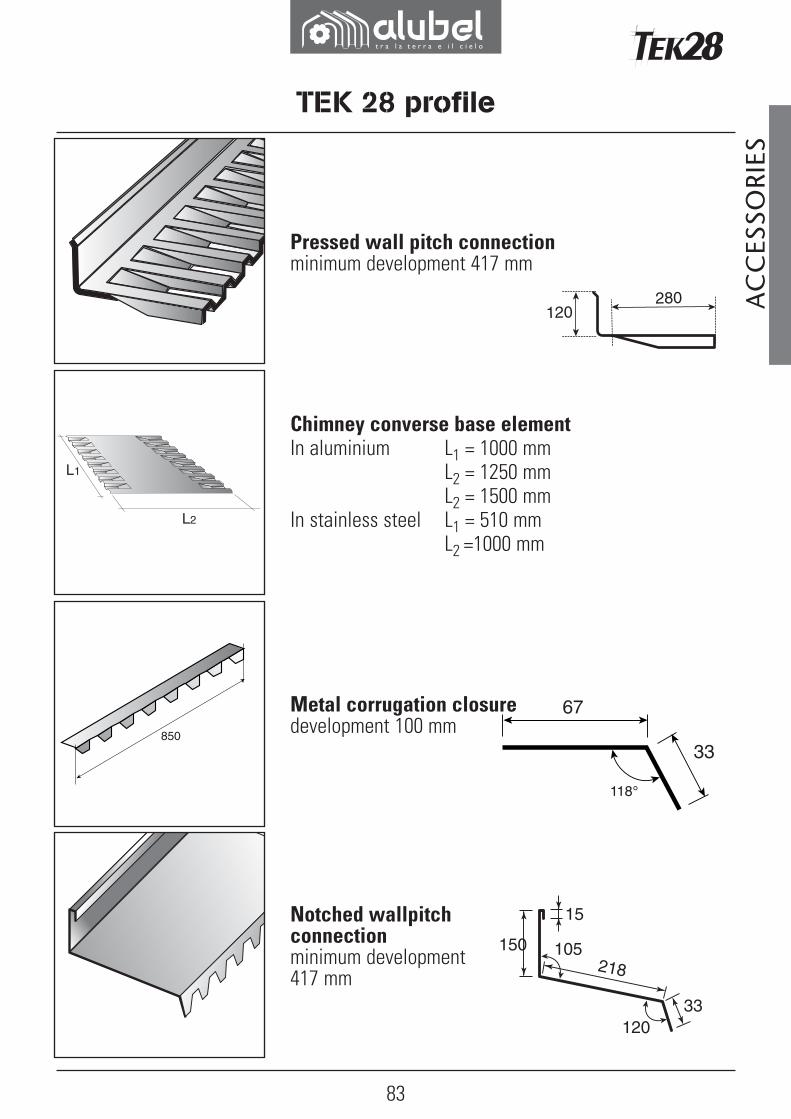
Pressed wall pitch connectionminimum development 417 mm
Notched wallpitch connectionminimum development 417 mm
Metal corrugation closuredevelopment 100 mm
Chimney converse base element In aluminium L1 = 1000 mm L2 = 1250 mm L2 = 1500 mmIn stainless steel L1 = 510 mm L2 =1000 mm

84
101
70
150
35
Under/over corrugation seal
Openable frameManual
Basic element for skylightsIn fibreglass
Press formed snow stopdevelopment 417 mm
TEK 28 profile
AC
CES
SORI
ES

85
470
Openable frameElectric
TEK 28 profile
AC
CES
SORI
ES
Sicurtetto walkwayraw aluminium3600 mm barsweight: 2,8 kg/m

86
1010
896
36 7627
,5
20 20
112 35
3676
112 20
27,5
Tek 28 polycarbonate profile
AC
CES
SORI
ES
1. The data given above are not a substitute for any locally existing directives.
2. The centre distance between the supports is calculated based on the characteristics of the material, sheet bending, the potential thrust of the wind and snow load, hail and on other applicable factors in accordance with common construction practices, professional experience and previous direct experience.
3. The above mentioned table refers to polycarbonate sheets supported by load bearing panels on both sides.
The contents of this calculation table are to be considered approximate and purely indicative. The structural calculation is the task of the designer and/or user in each single case.
Load[kg/m2]
thickness 1 mmSingle span Multiple span
50 1350 1550
75 1150 1350
100 1050 1200
125 1000 1150
150 900 1050
87
Tek 28 polycarbonate profile
AC
CES
SORI
ES
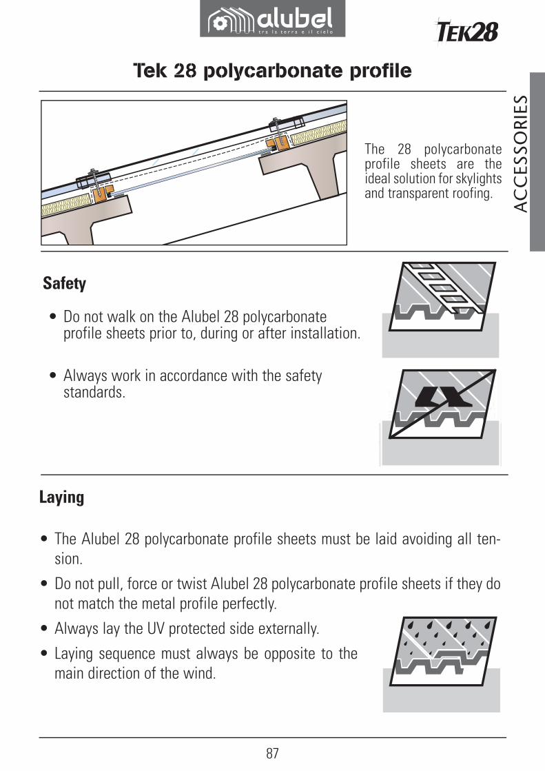
The 28 polycarbonate profile sheets are the ideal solution for skylights and transparent roofing.
Safety
• Do not walk on the Alubel 28 polycarbonate profile sheets prior to, during or after installation.
• Always work in accordance with the safety standards.
Laying
• The Alubel 28 polycarbonate profile sheets must be laid avoiding all ten-sion.
• Do not pull, force or twist Alubel 28 polycarbonate profile sheets if they do not match the metal profile perfectly.
• Always lay the UV protected side externally.
• Laying sequence must always be opposite to the main direction of the wind.
88
3 2
1
Tek 28 polycarbonate profile
AC
CES
SORI
ES
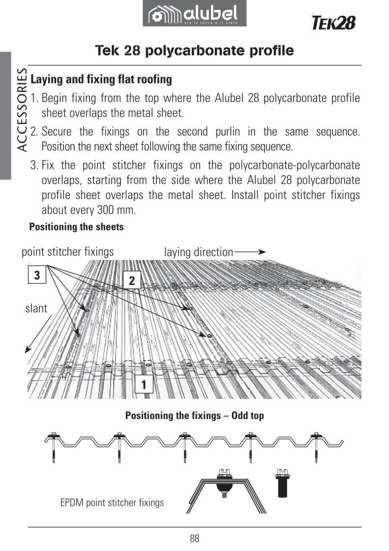
Positioning the fixings – Odd top
EPDM point stitcher fixings
point stitcher fixings
slant
laying direction
Positioning the sheets
Laying and fixing flat roofing 1. Begin fixing from the top where the Alubel 28 polycarbonate profile
sheet overlaps the metal sheet. 2. Secure the fixings on the second purlin in the same sequence.
Position the next sheet following the same fixing sequence.3. Fix the point stitcher fixings on the polycarbonate-polycarbonate
overlaps, starting from the side where the Alubel 28 polycarbonate profile sheet overlaps the metal sheet. Install point stitcher fixings about every 300 mm.
89
AC
CES
SORI
ES
Tek 28 polycarbonate profile
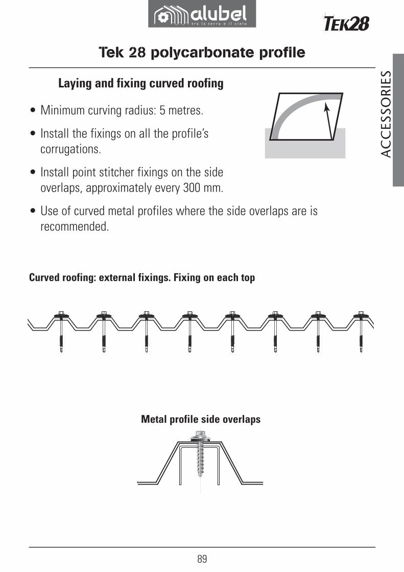
Curved roofing: external fixings. Fixing on each top
Metal profile side overlaps
Laying and fixing curved roofing
• Minimum curving radius: 5 metres.
• Install the fixings on all the profile’s corrugations.
• Install point stitcher fixings on the side overlaps, approximately every 300 mm.
• Use of curved metal profiles where the side overlaps are is recommended.

90
Tek 28 polycarbonate profile
AC
CES
SORI
ES Side overlap
• Start from the side where the Alubel 28 polycarbonate profile sheet overlaps the metal sheet.
• The opposite side of the Alubel 28 polycarbonate profile sheet must be overlapped by the next Alubel 28 polycarbonate profile sheet.
Head overlap
• Lay so it is aligned with the metal sheet.
• Maximum overlap: 15 cm from the fixing line.
• Minimum overlap: 5 cm from the fixing line.
• Apply the seal along the fixing line or two seals on the sides of the fixing line itself.
Fixings and seals
• Metal purlins - 6,3 x 65 mm self-drilling fixings. • Wood purlins - 6,5x 70 mm wood fixings.• EPDM seal, 55 or 65 Shore hardness, 25 mm ø• Never use PVC or metal seals that have not been
approved. • The use of ALUBLOK fixings is recommended.• In the case of curved roofing, it is advisable to use
caps shaped to match the corrugation, like the one shown here.

91
90°
Tek 28 polycarbonate profile
AC
CES
SORI
ESFixing suggestions
• Use suitable fixing tools.
• The fixing must be secured at a right angle with the sheet.
• IMPORTANT: never over tighten the fixings!
Cutting tools
• Handheld or table saw with fine teeth.
• Metal shears.
• Cut at a high rotation speed and low forward feed speed.

92
Tek 28 polycarbonate profile
AC
CES
SORI
ES Storing
• Store in the shade and protect from direct sunlight and rain.
• Do not cover with materials that absorb heat.
• Avoid contact with chemicals.
• Protect the sheets from all possible damage.
Fitting the seals
• Clean the surface before putting the seal in place.
• Put the seal in place gradually and evenly without any tension.
• Apply a strip along the fixing line or two on its sides.
Accessories
• Only use accessories approved by Alubel
• Silicone.
• Seals in butyl rubber or foam materials.
• Closing elements.
93
TEK 28 profile
AC
CES
SORI
ESIMPORTANT NOTES
• Make sure the UV protected side is always on the outside.
• Always install with compatible corrugated profiles.
• Avoid all tension sources.
• Pre-drill the fixing point making holes that are 2 mm bigger than the diameter of the fixing when fixing the base of the corrugation.
• Do not over tighten the fixings.
• Avoid contact with chemicals or installation where there are corrosive substances.
• Only use compatible accessories, i.e. seals, silicones, sealants, clo-sing elements etc. Soft PVC looks just like EPDM but it is not appro-ved for use with polycarbonate sheets.
• Avoid contact with non compatible chemicals, including lubricants for aluminium.

94
Straight translucent sheets in fibreglass with 1,8 kg/m2 Melinex
Curved translucent sheets r = 3 m in fibreglass with 2,1 kg/m2 Melinex
TEK 28 profile
Translucent polycarbonate sheets Colour: neutral white
AC
CES
SORI
ES
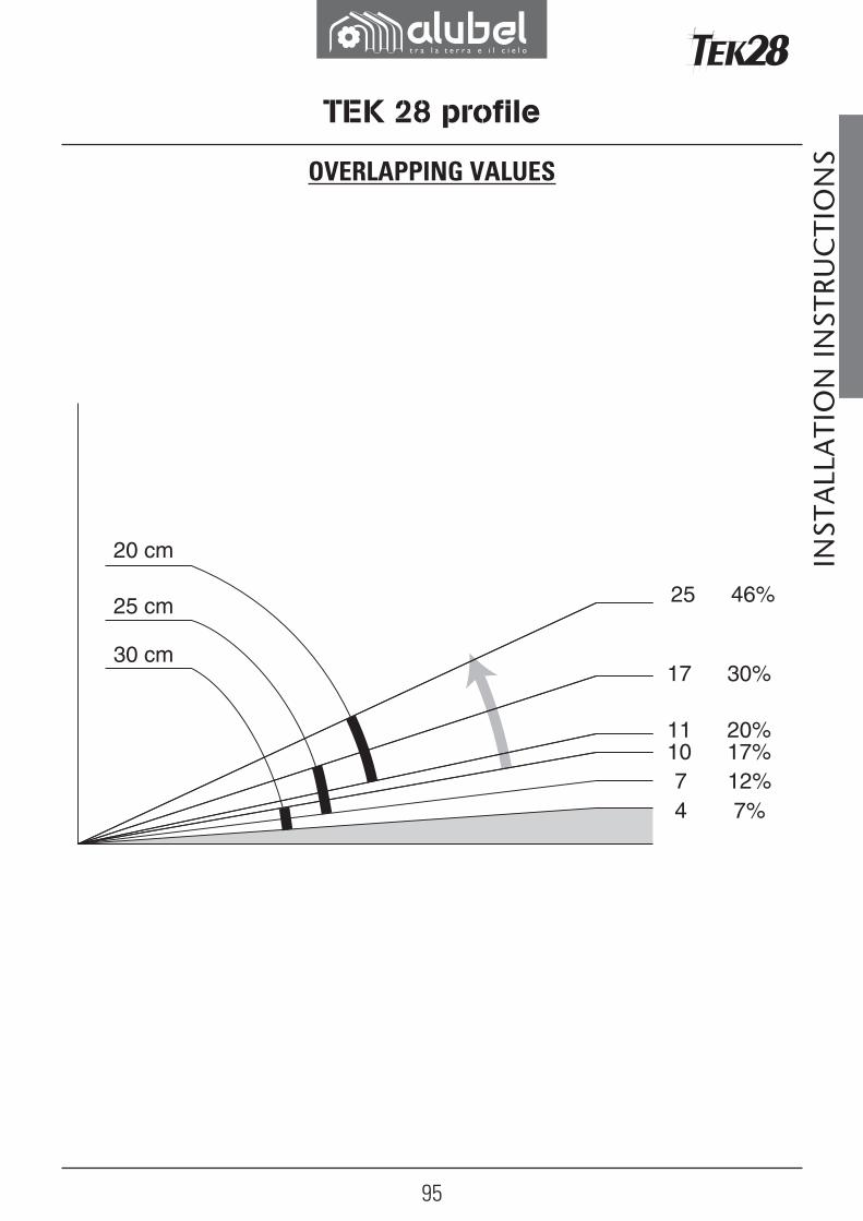
95
20 cm
25 cm
30 cm
25
17
1110
46%
30%
20%17%
7 12%4 7%
TEK 28 profile
INST
ALL
ATI
ON
INST
RUC
TIO
NSOVERLAPPING VALUES


