

Unit 5 - Turning

CA1 (35 %)◦ Assignments -15% (review, sketching, case
study)◦ BB Quiz -10% (turning, milling)◦ General Performance -10% (attitude,
attendance..)
CA2 (40%)◦ Practical (machining tape holder - individual)
CA3 (25%)◦ Mini Project (machining car chassis and
participating in Racing Challenge)

Learning Objectives:
List the components of a centre lathe Discuss the safety rules Discuss the use of tool holding
devices Discuss the characteristics of cutting
tool materials and inserts Watch and discuss video VC2495/8

What is the primary function of a centre lathe?
Can you name the components of a lathe?

What 2 movements are necessary before turning process can take place?
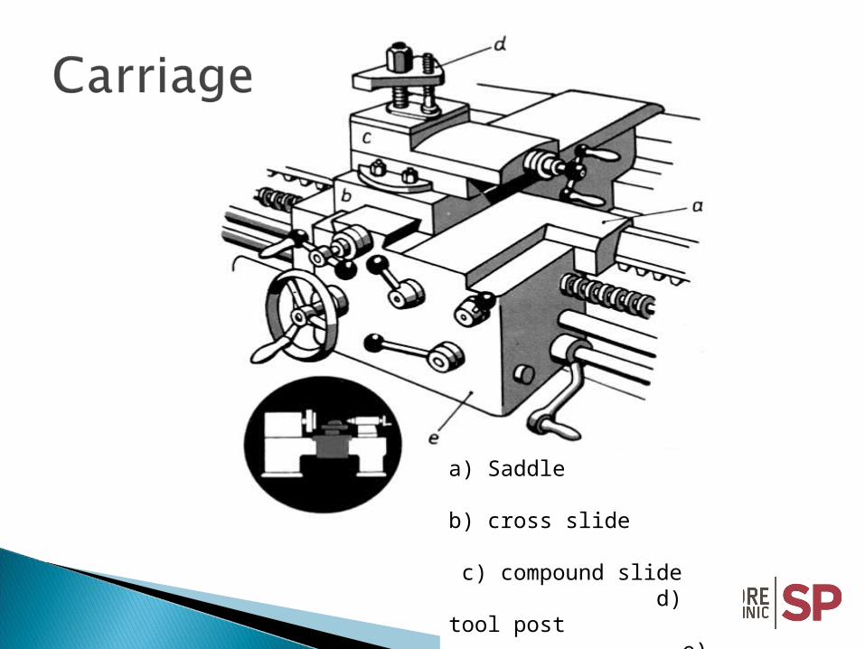
a) Saddle b) cross slide c) compound slide d) tool post e) apron

Knurling toolPartingtool
Chamfering tool
Facing andturning tool
Knifeturning tool
toolRadius forming
Undercuttingtool
Facing tool
Boringtool
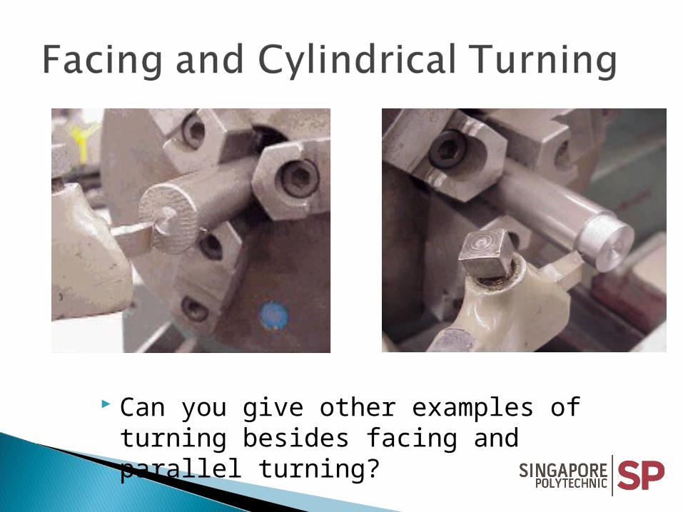
Can you give other examples of turning besides facing and parallel turning?

Compare and contrast the differences of a 4-way tool-post (above) and quick change tool-post?

On Centre – good finish
Above Centre- not cutting
Below Centre – poor finish
= Front Clearance = Wedge Angle

Locking screw
Insert
Insert holder
ChipBreaker
The carbide insert is locked by a locking screw or cam. Shape may be triangular (as above) or diamond, square or round.

Review 1
1. Define “Turning Operation”.2. State the effects of improper tool setting.3. List 10 safety precautions in the machine shop
and how would you categorised them?4. State the 3 purposes of facing operation.5. What is the main advantage of quick change
tool post?

Learning Objectives:
Compare and contrast 3-jaw and 4-jaw chucks
Explain the use of work holding support used in between centres
Discuss the use of other work holding devices like faceplate, mandrels and steadies.

Normally used for holding round or hexagonal stock.
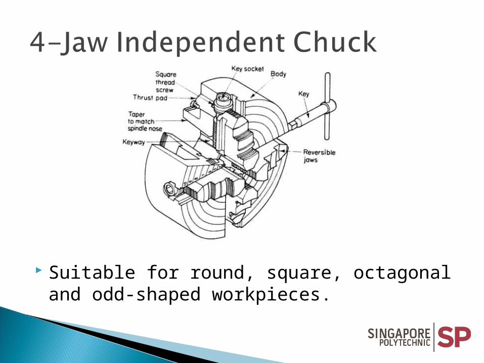
Suitable for round, square, octagonal and odd-shaped workpieces.


Long Workpiece
Normally used for turning a long workpiece supported between between centres. It requires 2 centres, a drive plate and a lathe dog.

Drive Plates

Compare and contrast live and plain centres.
Morse standard taper
Plain
Live
Sleeve2 Bearings


1. Plain solid mandrel – one size of bore
2. Gang mandrel – many workpieces with same Internal diameter
3. Expansion mandrel – slight difference (up to 2mm variation) in diameter
4. Cone mandrel – large variation in diameter allowed.
Workpiece

Fixed Steady
Travelling Steady

1. How would you hold a hollow thin wall round pipe for turning?
2. When is a faceplate used?
3. Explain the reason why the 3-jaw chuck is self-centred.
4. State the advantages of a 4-jaw chuck.

Learning Objectives:
Distinguish between Orthogonal and oblique cutting.
Discuss the tool geometry of a single-pointed tool.
Discuss the factors that influence metal cutting operations.
Discuss the types of chips

Cutting edge is set at 90° to the direction of movement. Chips in the form of a clock spring or a flat spiral Chips disposal problem & damage to workpiece surface.

Cutting edge is set at any angle other than 90º to the direction of tool movement.
Chips able to move freely away from workpiece Taking deeper cuts is possible surface finish is better with a nose radius

1) Side Rake angle : provides a cutting edge to allow chips to escape during cutting.
2) Back Rake angle : promotes smooth chip flow and good finishing
3) Front Relief angle : prevents tool end from rubbing
4) Side Relief angle: allows the tool to feed into the work
Minor cutting edge
Minor cutting edge angle
Major cutting edge angle
Major cutting edge
Nose Radius
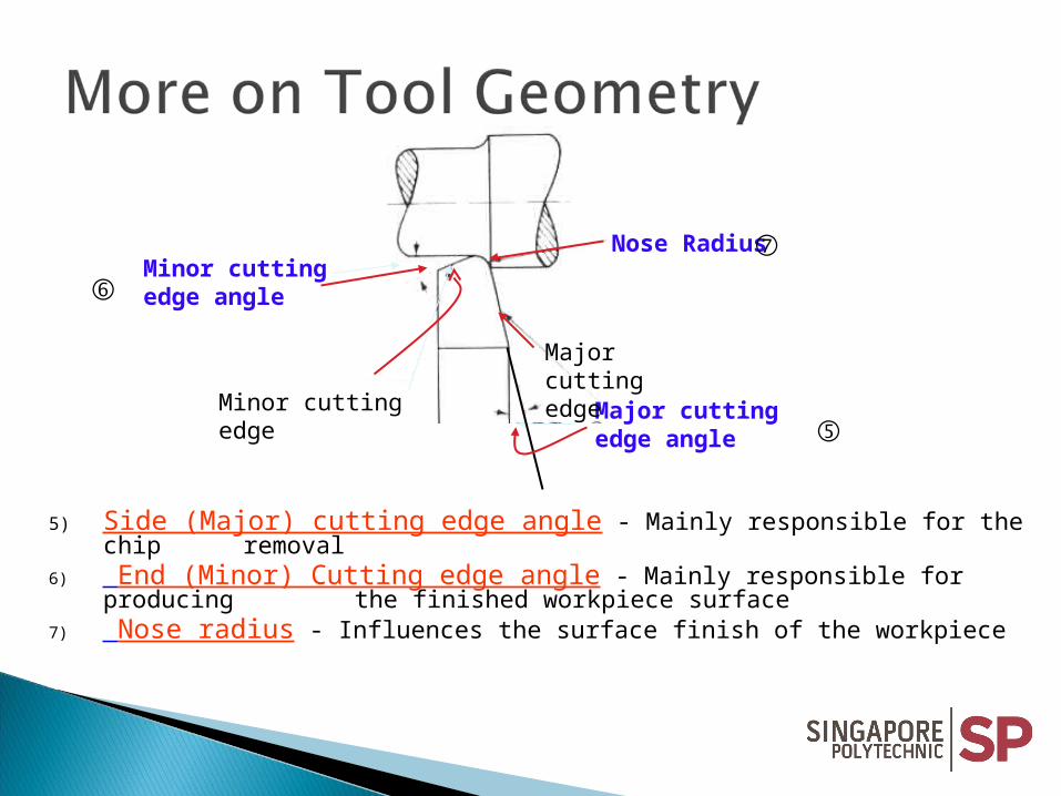
5) Side (Major) cutting edge angle - Mainly responsible for the chip removal
6) End (Minor) Cutting edge angle - Mainly responsible for producing the finished workpiece
surface7) Nose radius - Influences the surface finish of the workpiece
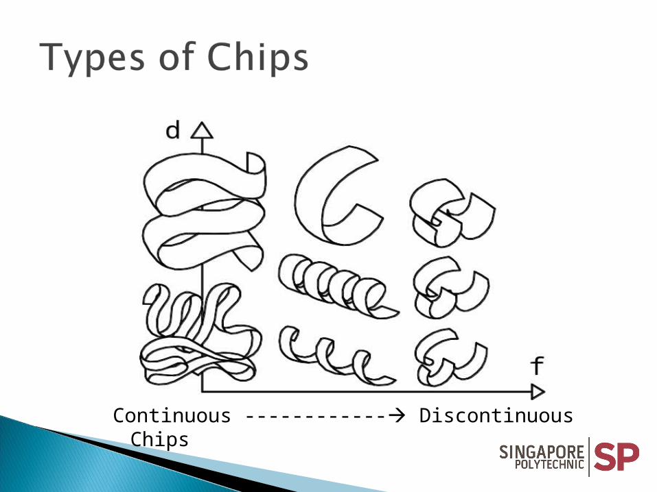
Continuous ------------ Discontinuous Chips

1. Compressive stress cause movement of metal.
2. Then, compression increases until plastic flow or rupture (or fracture) occurs.
◦ Ductile material - continuous chip is formed
◦ Brittle materials - rupture takes place withsmall discontinuous fractured chip

Brittle material, small rake angle, large depth of cut or feedrate and no cutting fluid

Ductile materials, large rake angle, small depth of cut or feedrate and efficient use of cutting fluid.

Higher values in depth of cut & feedrate, lower value for rake angle and wrong application of coolant produced higher friction.
• Compare and contrast orthogonal and oblique cutting.
• With simple sketches, show the tool geometry of single-pointed cutters.
• List the three types of chip formation.
• State the conditions for the formation of continuous chip.
Learning Objectives:
Describe 3 cutting forces acting on the tool Discuss the relationship of cutting forces and the
following:◦ rake angle◦ depth of cut◦ feedrate◦ cutting speed, and◦ plan approach angle

Tangential and Axial Forces

Besides Tangential and Axial Forces, there is also a Radial Force.

Tangential Force (Ft) – tangential to the work surface, main power-consuming.
Axial Force (Fa) – parallel to the work axis and opposing the lengthwise feed direction.
Radial Force (Fr) – present only in oblique cutting and opposing the crosswise feed direction.
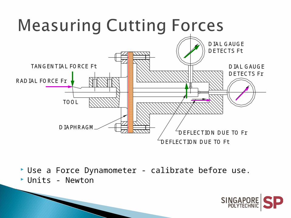
Use a Force Dynamometer - calibrate before use. Units - Newton

A Test piece
Ft
Rake angle ()
Dry
With coolant
Uniform thickness
Side Rake angle varies from 0 to 40º in steps of 5º Lower Tangential force when Rake angle is smaller.

FtFt
Fa
Test piece with stepped-wall
Depth of cut (mm)
Depth of Cut varies from 2 to 10 mm. Bigger Tangential and Axial forces
encountered when Depth of cut increases.
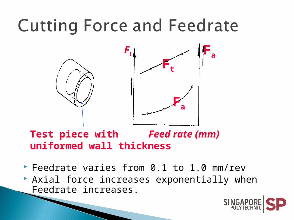
Test piece withuniformed wall thickness
Ft Fa
Fa
Ft
Feed rate (mm)
Feedrate varies from 0.1 to 1.0 mm/rev Axial force increases exponentially when Feedrate
increases.

Ft
Breakage point of cutter
Cutting speeds (m/min)
Cutting Speed varies from 30º to 80º of allowable speed value
No change in tangential force before tool break-up.

Cutting Force and Approach angle,
Plan Approach Angle varies from 45º to 90º. Axial force equals to Radial force at 45º. Radial force equals to zero at 90º and
tangential force is at maximum.
1. Describe the forces acting on the cutter during orthogonal and oblique cutting.
2. Sketch the graph and explain test results when the rake angle was varied.
3. Explain the effects of depth of cut and feedrate on the following items:• Chip thickness
• Cutting force
4. Explain the effects of the cutting forces when plan approach angle is set at 45º.

Learning Objectives: Discuss the differences of cutting speed, spindle
speed and feedrate. Calculate the machining time, cutting power,
feed power and specific metal removal rate. Discuss the different types of cutting tool
materials. Describe the effects of positive and negative
back rake angle Explain the functions of cutting fluid.

WORKPIECE MATERIALS
FEED (mm/rev) CUTTINGSPEED (m/min)
Aluminium 0.2 – 1.0 70 – 100
Brass (Alpha, Ductile)
0.2 – 1.0 50 – 80
Brass (free-cutting) 0.2 – 1.5 70 – 100
Bronze (phosphor) 0.2 – 1.0 35 – 70
Cast iron (grey) 0.15 – 1.0 25 – 40
Copper 0.2 – 1.0 35 - 70
Steel (mild) 0.2 – 1.0 35 - 70
Steel (medium carbon)
0.15 – 0.7 30 - 35
Steel (alloy, high-tensile)
0.08 – 0.3 5 – 10
Thermo-setting plastic
0.2 – 1.0 35 - 50
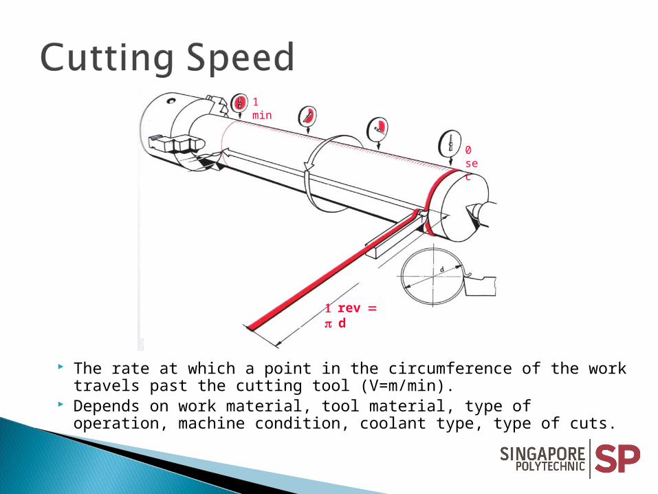
0 sec
1 min
rev d
The rate at which a point in the circumference of the work travels past the cutting tool (V=m/min).
Depends on work material, tool material, type of operation, machine condition, coolant type, type of cuts.

The spindle speed is the number or revolutions turned in one min.
N = V (rev/min) d
The Spindle Speed, N depends on: 1. the cutting speed, V and 2. the diameter, d of the workpiece.
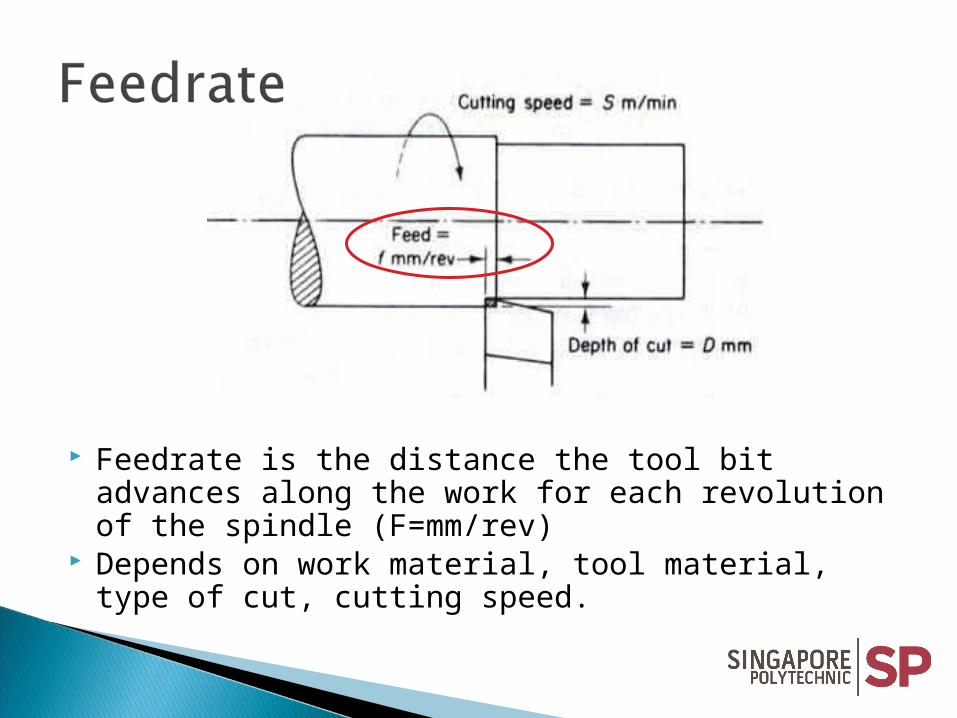
Feedrate is the distance the tool bit advances along the work for each revolution of the spindle (F=mm/rev)
Depends on work material, tool material, type of cut, cutting speed.

Calculate the spindle speed, to the nearest rev/min, for turning a 50 mm diameter bar at a cutting speed of 40 m/min.
1000 * V where, N = spindle speedN = ---------------- V = 40 m/min D D = 50 mm
1000 * 40 = ------------------ = 255 (rev / min) 3.142 * 50

Calculate the time taken to turn a brass component 65 mm diameter by 95 mm long, if the cutting speed is 45 m/min and the feed is 0.6 mm/rev. Only one cut is to be taken.
N = 1000( V / ( D)) Thus, time taken, THence, = L / Fm N = (45 * 1,000) / (65 * ) = 95 / 132.2 = 220.3 rev/min = 0.71806 min
= 43.1 secMaterial feed rate, Fm = Fr * N
= 0.6 * 220.3 = 132.2 mm/ min
N = 1000( V / ( D)) Thus, time taken, THence, = L / Fm N = (45 * 1,000) / (65 * ) = 95 / 132.2 = 220.3 rev/min = 0.71806 min
= 43.1 secMaterial feed rate, Fm = Fr * N
= 0.6 * 220.3 = 132.2 mm/ min

1. Describe the forces acting on the cutter during orthogonal and oblique cutting.
2. Sketch the graph and explain test results when the rake angle was varied.
3. Explain the effects of depth of cut and feedrate on the following:
• Chip thickness
• Cutting force
4. Explain the effects of the cutting forces when plan approach angle is set at 45º.

Use Ft
Work done = force * dist moved
= force * Circumference * N
= F * 2 r N
F * d NPower is the rate of doing work
= work done time taken
= F * d N Nm or watts 1000*60 sec
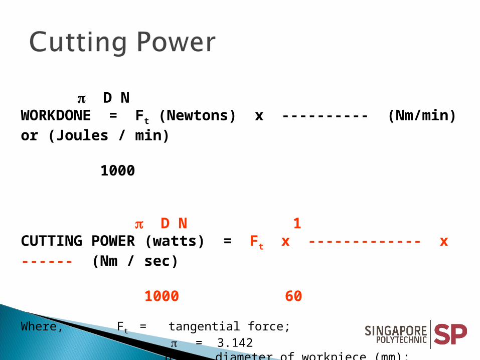
D NWORKDONE = Ft (Newtons) x ---------- (Nm/min) or (Joules / min) 1000
D N 1CUTTING POWER (watts) = Ft x ------------- x ------ (Nm / sec) 1000 60
Where, Ft = tangential force; = 3.142
D = diameter of workpiece (mm); N = rotational speed in rpm
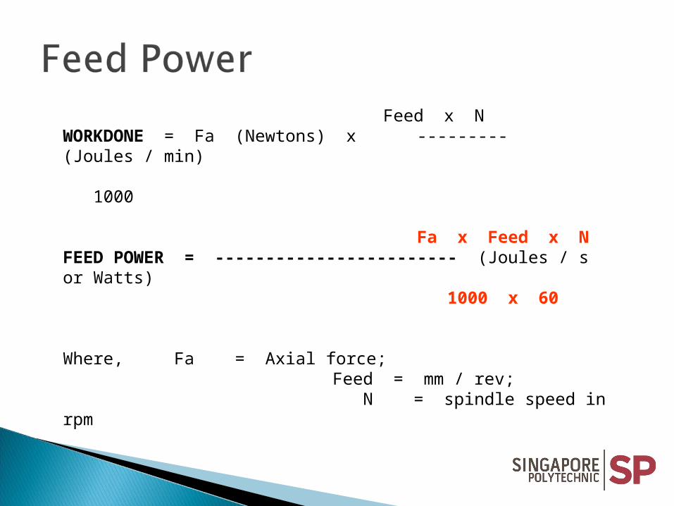
Feed x NWORKDONE = Fa (Newtons) x --------- (Joules / min) 1000
Fa x Feed x NFEED POWER = ------------------------ (Joules / s or Watts) 1000 x 60
Where, Fa = Axial force; Feed = mm / rev; N = spindle speed in rpm
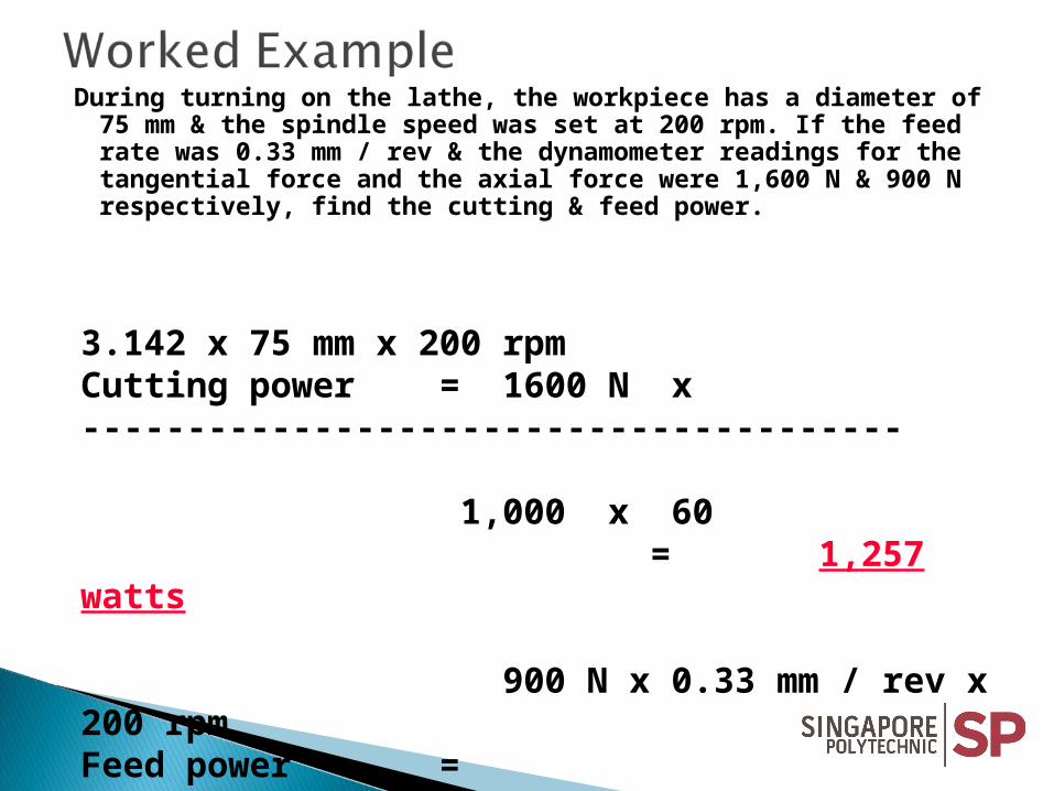
During turning on the lathe, the workpiece has a diameter of 75 mm & the spindle speed was set at 200 rpm. If the feed rate was 0.33 mm / rev & the dynamometer readings for the tangential force and the axial force were 1,600 N & 900 N respectively, find the cutting & feed power.
3.142 x 75 mm x 200 rpmCutting power = 1600 N x --------------------------------------- 1,000 x 60
= 1,257 watts
900 N x 0.33 mm / rev x 200 rpmFeed power = ----------------------------------------------
1,000 x 60 = 0.99 Watts
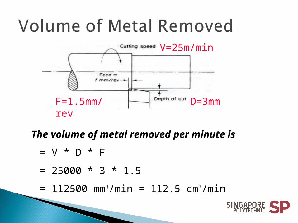
V=25m/min
D=3mmF=1.5mm/rev
The volume of metal removed per minute is
= V * D * F
= 25000 * 3 * 1.5
= 112500 mm3/min = 112.5 cm3/min
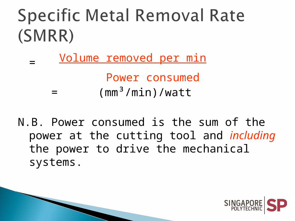
= Volume removed per min
Power consumed
= (mm³/min)/watt
N.B. Power consumed is the sum of the power at the cutting tool and including the power to drive the mechanical systems.
High Carbon steel HSS Cemented carbide (contains 90% carbide
powder and 10% cobalt as binder)
Cemented ceramic (contains 95% Al2O3) Diamond

Ability to: Retain hardness at high temperature Resist Shock i.e. toughness Resist Wear Reasonably cheap Acceptable mechanical properties
Good abrasion resistance Slow rate of wear Hot Hardness properties Vibration and chatter must be avoided Very brittle Unable to withstand shock and bending
loads Used it as a throwaway tip or insert.

Normal force, N, on unsupported part
Tendency to break
Lower cutting forces
positive rake
Cutting tool
N

Normal force, N, on supported part
Less likely to break Operate at higher
speed Higher compressive
forces
Nnegative rake

Higher cutting speed possible Better surface finish Longer Tool life Lower Power consumption Better dimensional accuracy
1. Explain the difference between cutting speed and spindle speed.
2. What are the factors that determine cutting speed?
3. What is SMRR used for?4. Explain the toughness of cutting tool
material.5. Compare and contrast positive and
negative back rake angle.

Next Lesson Introduction to Milling Operations


![E[M]CONOMY moves! - s3.amazonaws.coms3.amazonaws.com/machinetools_production/uploads/978162/EMCO… · concept turn 55 concept turn 105 concept turn 250 concept turn 450 emco maxxturn](https://static.documents.pub/doc/80x56/5aa72fe87f8b9a50528c01d9/emconomy-moves-s3-concept-turn-55-concept-turn-105-concept-turn-250-concept.jpg)


