
42 STATES TYPE SJK TEST SWITCHES
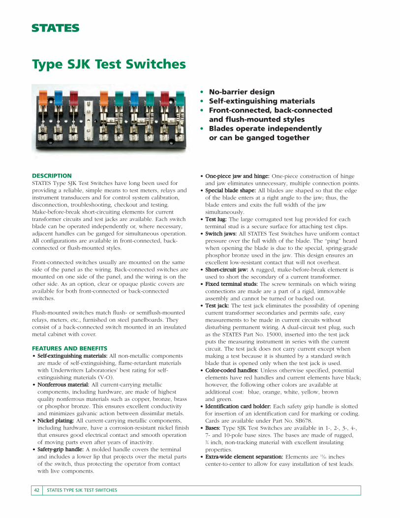
• No-barrier design• Self-extinguishing materials• Front-connected, back-connected
and flush-mounted styles• Blades operate independently
or can be ganged together
Type SJK Test Switches
DESCRIPTIONSTATES Type SJK Test Switches have long been used forproviding a reliable, simple means to test meters, relays andinstrument transducers and for control system calibration,disconnection, troubleshooting, checkout and testing.Make-before-break short-circuiting elements for currenttransformer circuits and test jacks are available. Each switchblade can be operated independently or, where necessary,adjacent handles can be ganged for simultaneous operation.All configurations are available in front-connected, back-connected or flush-mounted styles.
Front-connected switches usually are mounted on the sameside of the panel as the wiring. Back-connected switches aremounted on one side of the panel, and the wiring is on theother side. As an option, clear or opaque plastic covers areavailable for both front-connected or back-connectedswitches.
Flush-mounted switches match flush- or semiflush-mountedrelays, meters, etc., furnished on steel panelboards. Theyconsist of a back-connected switch mounted in an insulatedmetal cabinet with cover.
FEATURES AND BENEFITS• SSeellff--eexxttiinngguuiisshhiinngg mmaatteerriiaallss:: All non-metallic components
are made of self-extinguishing, flame-retardant materialswith Underwriters Laboratories’ best rating for self-extinguishing materials (V-O).
• NNoonnffeerrrroouuss mmaatteerriiaall:: All current-carrying metalliccomponents, including hardware, are made of highestquality nonferrous materials such as copper, bronze, brassor phosphor bronze. This ensures excellent conductivityand minimizes galvanic action between dissimilar metals.
• NNiicckkeell ppllaattiinngg:: All current-carrying metallic components,including hardware, have a corrosion-resistant nickel finishthat ensures good electrical contact and smooth operationof moving parts even after years of inactivity.
• SSaaffeettyy--ggrriipp hhaannddllee:: A molded handle covers the terminaland includes a lower lip that projects over the metal partsof the switch, thus protecting the operator from contactwith live components.
• OOnnee--ppiieeccee jjaaww aanndd hhiinnggee:: One-piece construction of hingeand jaw eliminates unnecessary, multiple connection points.
• SSppeecciiaall bbllaaddee sshhaappee:: All blades are shaped so that the edgeof the blade enters at a right angle to the jaw; thus, theblade enters and exits the full width of the jawsimultaneously.
• TTeesstt lluugg:: The large corrugated test lug provided for eachterminal stud is a secure surface for attaching test clips.
• SSwwiittcchh jjaawwss:: All STATES Test Switches have uniform contactpressure over the full width of the blade. The “ping” heardwhen opening the blade is due to the special, spring-gradephosphor bronze used in the jaw. This design ensures anexcellent low-resistant contact that will not overheat.
• SShhoorrtt--cciirrccuuiitt jjaaww:: A rugged, make-before-break element isused to short the secondary of a current transformer.
• FFiixxeedd tteerrmmiinnaall ssttuuddss:: The screw terminals on which wiringconnections are made are a part of a rigid, immovableassembly and cannot be turned or backed out.
• TTeesstt jjaacckk:: The test jack eliminates the possibility of openingcurrent transformer secondaries and permits safe, easymeasurements to be made in current circuits withoutdisturbing permanent wiring. A dual-circuit test plug, suchas the STATES Part No. 15000, inserted into the test jackputs the measuring instrument in series with the currentcircuit. The test jack does not carry current except whenmaking a test because it is shunted by a standard switchblade that is opened only when the test jack is used.
• CCoolloorr--ccooddeedd hhaannddlleess:: Unless otherwise specified, potentialelements have red handles and current elements have black;however, the following other colors are available atadditional cost: blue, orange, white, yellow, brownand green.
• IIddeennttiiffiiccaattiioonn ccaarrdd hhoollddeerr:: Each safety grip handle is slottedfor insertion of an identification card for marking or coding.Cards are available under Part No. SB678.
• BBaasseess:: Type SJK Test Switches are available in 1-, 2-, 3-, 4-,7- and 10-pole base sizes. The bases are made of rugged,3⁄4 inch, non-tracking material with excellent insulatingproperties.
• EExxttrraa--wwiiddee eelleemmeenntt sseeppaarraattiioonn:: Elements are 11⁄16 inchescenter-to-center to allow for easy installation of test leads.

STATES TYPE SJK TEST SWITCHES 43
HHaannddllee CCoolloorrss:: The standard colors for handles are red forpotential handles and black for current handles. Handles arealso available in other colors. To specify non-standard colors, add to the element numberthe appropriate color code:CCoolloorr CCoolloorr CCooddeeBlack kkBlue bbGreen ggOrange ee
To order a switch with handles in non-standard colors, youmust specify the arrangement with colors indicated. Forexample, to order a 10-pole switch with special handlecolors, specify: AArrrraannggeemmeenntt:: 1k/10g/1y/10b/1e/10r/1wGGaannggeedd hhaannddlleess:: You may specify a yoking bar to gangadjacent handles. For example, to order a switch with the adjacent potentialsganged, you must specify: GGaanngg aallll ppootteennttiiaallss
HHiinnggee ppoossiittiioonn:: The “U” in an arrangement indicates the hinge is positioned upside down from the typicalarrangement.
BBaasseess:: An 8- or 9-pole test switch is built on a 10-pole base. A 5-, 6-, or 7-pole test switch usually is built on a 7-polebase but can be provided on a 10-pole base if desired.
The part numbers under the arrangements on the followingpages are for front-connected switches without covers,which are designated by the first three characters in thePart No., 20K. EExxaammppllee:: 2200KK1100--EE
COVERSAny front- or back-connected switch, up to 10 poles, canbe ordered with a cover. Covers are available on 4-, 7- and10-pole bases. Although you may choose a larger base,usually a 1- to 4-pole switch is built on a 4-pole base; a 5- to 7-pole switch is built on a 7-pole base; and an 8- to10-pole switch is built on a 10-pole base. TToo oorrddeerr ffrroonntt--ccoonnnneecctteedd sswwiittcchheess To order front-connected switches without covers, specify the Part No. shown under the arrangements on thefollowing pages. EExxaammppllee:: 2200KK1100--EEFor covers, change the 20K prefix to one of the followingprefixes:CCoovveerr PPrreeffiixxFront-connected, slotted, clear 60KFront-connected, slotted, opaque 80KEExxaammppllee:: 6600KK1100--EETToo oorrddeerr bbaacckk--ccoonnnneecctteedd sswwiittcchheessTo order back-connected switches without covers, specify the desired arrangement and add the suffix -B. EExxaammppllee:: 2200KK1100--EE--BBCovers are available for 4-, 7- and 10- pole switches. For covers, add the appropriate prefix:CCoovveerr PPrreeffiixxBack-connected, solid, opaque 90KBack-connected, solid, clear 70KEExxaammppllee:: 9900KK1100--EE--BBTToo oorrddeerr fflluusshh--mmoouunntteedd sswwiittcchheessAdd the prefix GG-- to the number of the desiredarrangement. EExxaammppllee:: GG--2200KK1100--EEFlush-mounted switches are provided with a cover. (The prefix GG-- mentioned above designates a flush-mountedswitch and its’ standard cover.)
SPECIAL ORDERSSSppeecciiaall AArrrraannggeemmeennttss:: In addition to the typicalarrangements shown on the following pages, specialarrangements are available. These can be made of anycombination of potential or current elements, with amaximum of 10 poles. For more information, refer to thefollowing example and illustrations on Page 47. EExxaammppllee:: To order a customized, 10-pole, back-connectedswitch with a clear, back-connected cover, specify:SSwwiittcchh TTyyppee:: STATES Type SJK NNoo.. ooff ppoolleess:: 10-pole test switch**AArrrraannggeemmeenntt:: 1-10-1-10-1-10-1SSttyyllee:: Back-connectedCCoovveerr:: Clear, back-connected**AArrrraannggeemmeennttss sshhoouulldd bbee ggiivveenn aass ffrroonntt vviieeww ooff sswwiittcchh,,lleefftt ttoo rriigghhtt..
ORDERING INFORMATION
SSoocckkeett WWrreenncchh aanndd IInnsseerrttTo speed installation of the terminal nuts on STATES TestSwitches, the socket wrench (Part No. 16028) and 3⁄8 inch insert (Part No. 16027) are available.
TThhee ssccrreewwddrriivveerr aattttaacchhmmeenntt (Part No. 16022) makes this wrench your complete meterinstallation tool.
OPTIONAL ACCESSORIES
CCoolloorr CCoolloorr CCooddeeRed rrWhite wwYellow yyBrown nn
DDuuaall CCiirrccuuiitt PPlluuggBy inserting the STATES Dual CircuitPlug (Part No. 15000) into the test jack,safe measurement can be made ofcurrent transformer secondary current.
SSeeee AAcccceessssoorriieess oonn ppaaggee 6677..
44 STATES TYPE SJK TEST SWITCHES
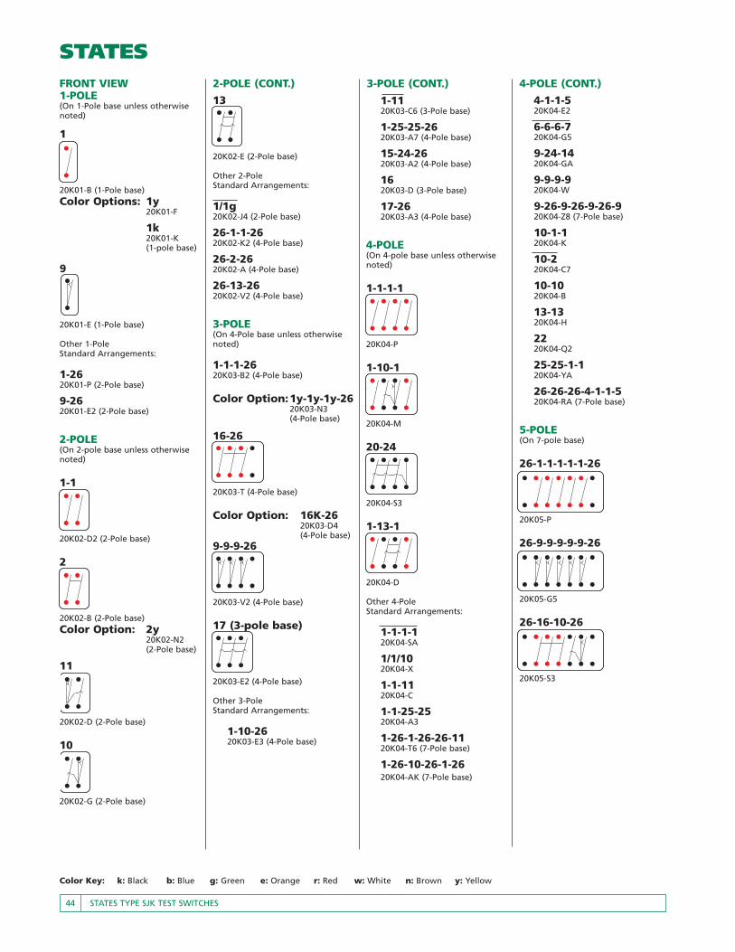
Color Key: k: Black b: Blue g: Green e: Orange r: Red w: White n: Brown y: Yellow
13
20K02-E (2-Pole base)
Other 2-PoleStandard Arrangements:
1/1g20K02-J4 (2-Pole base)
26-1-1-2620K02-K2 (4-Pole base)
26-2-2620K02-A (4-Pole base)
26-13-2620K02-V2 (4-Pole base)
3-POLE(On 4-Pole base unless otherwisenoted)
1-1-1-2620K03-B2 (4-Pole base)
Color Option:1y-1y-1y-2620K03-N3(4-Pole base)
16-26
20K03-T (4-Pole base)
Color Option: 16K-2620K03-D4(4-Pole base)
9-9-9-26
20K03-V2 (4-Pole base)
17 (3-pole base)
20K03-E2 (4-Pole base)
Other 3-PoleStandard Arrangements:
1-10-2620K03-E3 (4-Pole base)
2-POLE (CONT.)1-1120K03-C6 (3-Pole base)
1-25-25-2620K03-A7 (4-Pole base)
15-24-2620K03-A2 (4-Pole base)
16 20K03-D (3-Pole base)
17-2620K03-A3 (4-Pole base)
4-POLE(On 4-pole base unless otherwisenoted)
1-1-1-1
20K04-P
1-10-1
20K04-M
20-24
20K04-S3
1-13-1
20K04-D
Other 4-PoleStandard Arrangements:
1-1-1-120K04-SA
1/1/1020K04-X
1-1-1120K04-C
1-1-25-2520K04-A3
1-26-1-26-26-1120K04-T6 (7-Pole base)
1-26-10-26-1-2620K04-AK (7-Pole base)
3-POLE (CONT.)4-1-1-520K04-E2
6-6-6-720K04-G5
9-24-1420K04-GA
9-9-9-920K04-W
9-26-9-26-9-26-920K04-Z8 (7-Pole base)
10-1-120K04-K
10-220K04-C7
10-1020K04-B
13-1320K04-H
2220K04-Q2
25-25-1-120K04-YA
26-26-26-4-1-1-520K04-RA (7-Pole base)
5-POLE(On 7-pole base)
26-1-1-1-1-1-26
20K05-P
26-9-9-9-9-9-26
20K05-G5
26-16-10-26
20K05-S3
4-POLE (CONT.)FRONT VIEW1-POLE(On 1-Pole base unless otherwisenoted)
1
20K01-B (1-Pole base)Color Options: 1y
20K01-F
1k20K01-K(1-pole base)
9
20K01-E (1-Pole base)
Other 1-PoleStandard Arrangements:
1-2620K01-P (2-Pole base)
9-2620K01-E2 (2-Pole base)
2-POLE(On 2-pole base unless otherwisenoted)
1-1
20K02-D2 (2-Pole base)
2
20K02-B (2-Pole base)Color Option: 2y
20K02-N2 (2-Pole base)
11
20K02-D (2-Pole base)
10
20K02-G (2-Pole base)
STATES TYPE SJK TEST SWITCHES 45
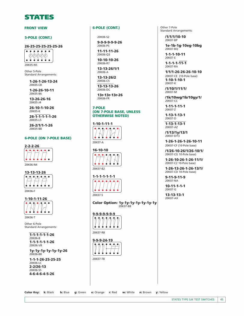
Color Key: k: Black b: Blue g: Green e: Orange r: Red w: White n: Brown y: Yellow
26-25-25-25-25-25-26
20K05-N5
Other 5-PoleStandard Arrangements:
1-26-1-26-13-2420K05-C8
1-26-26-10-1120K05-B6
13-26-26-1620K05-J4
26-10-1-10-2620K05-K
26-1-1-1-1-1-2620K05-L5
26-2/1/1-1-2620K05-B8
6-POLE (ON 7-POLE BASE)
2-2-2-26
20K06-N4
13-13-13-26
20K06-F
1-10-1-11-26
20K06-T
Other 6-PoleStandard Arrangements:
1-1-1-1-1-1-2620K06-B1-1-1-1-1-1-2620K06-V8
1y-1y-1y-1y-1y-1y-2620K06-B8
1-1-1-26-25-25-2520K06-LC2-2/26-1320K06-S54-6-4-6-4-5-26
5-POLE (CONT.) 20K06-S2
9-9-9-9-9-9-2620K06-P5
11-11-11-2620K06-Q3
10-10-10-2620K06-R7
13-13-26/1/120K06-A
13-13-26/220K06-C5
13-13-13-2620K06-DC
13r-13r-13r-2620K06-FR
7-POLE (ON 7-POLE BASE, UNLESS OTHERWISE NOTED)
1-10-1-11-1
20K07-A
16-10-10
20K07-B2
1-1-1-1-1-1-1
20K07-S
Color Option: 1y-1y-1y-1y-1y-1y-1y20K07-B8
9-9-9-9-9-9-9
20K07-R8
9-9-9-24-19
20K07-T8
6-POLE (CONT.) Other 7-PoleStandard Arrangements:
/1/1/1/10-1020K07-BP
1e-1b-1g-10eg-10bg20K07-BQ
1-1-1-10-1120K07-E
1-1-1-1-11-120K07-RA
1/1/1-26-26-26-10-1020K07-CE (10-Pole base)1-10-1-10-120K07-K
/1/10/1/11/1/20K07-M
/1k/10wg/1b/10gy/1/20K07-CC
1-11-1-11-120K07-Z
1-13-1-13-120K07-D
1-13-1-13-120K07-AZ
/1/13/1y/13/120K07-DY3
1-26-1-26-1-26-10-1120K07-CF (10-Pole base)
/1/26-10-26/1/26-10/1/20K07-CG 10-Pole base)
1-26-10-26-1-26-11/1/20K07-C2 10-Pole base)
1-26-13-26-1-26-13/1/20K07-CD 10-Pole base)
9-11-9-11-920K07-NA
10-11-1-1-120K07-G
13-13-13-120K07-AX
FRONT VIEW

46 STATES TYPE SJK TEST SWITCHES
Color Key: k: Black b: Blue g: Green e: Orange r: Red w: White n: Brown y: Yellow
9-POLE (ON 10-POLE BASE)
1-1-1-13-13-13-26
20K09-C
1-1-1-26-4-6-4-6-4-5
20K09-D8
1-10-1-10-1-10-26
20K09-K
16-10-10-10-26
20K09-XU
Other 9-PoleStandard Arrangements:
1-1-1-1-1-1-1-1-1-2620K09-W
1-1-1-1-1-13-13-2620K09-C7
1-1-1-10-10-10-2620K09-U
1-1-1-11-11-11-2620K09-P
1-1-24-26-4-6-4-6-4-520K09-F8
1-10-10-1-10-1-2620K09-G
1-11-1-11-1-11-2620K09-N1-13-1-13-1-13-2620K09-H
9-9-9-9-9-9-9-9-9-2620K09-Q4
9-10-10-10-10-2620K09-U7
10-10-10-1-1-1-2620K09-D
10-10-10-10-9-2620K09-AB
11-9-11-9-11-9-2620K09-XB
10-POLE (ON 10-POLE BASE)
1-10-1-10-1-10-1
20K10-E
Color Options:1-10bw-1y-10gw-1e-10nw-1w20K10-BZ
1-10rk-1w-10wb-1g-10ge-1k20K10-Z5
1-1-1-1-13-13-13
20K10-C
9-9-9-9-24-14-19
20K10-MA
1-1-1-1-1-1-1-1-1-1
20K10-Y
Color Options:1y-1y-1y-1y-1y-1y-1y-1y-1y-1y20K10-H8
1k-1k-1k-1k-1k-1k-1k-1k-1k-1k20K10-K8
1-1-1-1-10-10-1020K10-BT
1e-1b-1-24-10eg-10bg-10rg20K10-BV
/1/1/1/24-11-11-1120K10-D7
1-1-10-10-1-1-1-120K10-BB
1-6-1-6-1-6-4-4-4-2420K10-X
/1/10/1/10/1/10/1/20K10-EM
1-13-1-13-1-13-120K10-G
/1/13/1/13/1/13/1y/20K10-W5
1-13-1-13-1-13-2420K10-F
/1/13/1/13/1/13/24/20K10-M
2-2-2-2-220K10-AA
8-POLE (ON 10-POLE BASE)
26-1-10-1-1-11-1-26
20K08-B
26-1-1-1-1-13-13-26
20K08-CD
9-9-9-9-26-26-9-9-9-9
20K08-U9
Color Option:9r-9r-9r-9r-26-26-9r-9r-9r-9r20K08-XA
Other 8-PoleStandard Arrangements:
1b/1g/1/24/-26-10-26-11rr20K08-CF
26-1-1-1-1-1-1-1-1-2620K08-N
26-1-1-1-1-1-1-1-1-2620K08-AB
26-1-1-1-1-10-10-2620K08-PE
26-1-1-1-1-10-11-2620K08-E2
26-1/1/1/1/13-13-2620K08-B6
26/1/6/1/6-4/1/3/1/2620K08-CG
26-1r-6r-9k/1k/1w-9w-5g-1g-2620K08-P6
26-1-10ek-1y-1w-10gk-1k-2620K08-ME
26-1-10-10-10-1-2620K08-F7
26-1-13-1-1-13-1-2620K08-J
26-9-9-9-9-9-9-9-9-2620K08-T9
26-9-9-9-24-19-5-2620K08-TE
26-10-10-10-1-1-2620K08-V
26-10-10-10-10-2620K08-K6
26-16-24-13-13-2620K08-JE
FRONT VIEW

STATES TYPE SJK TEST SWITCHES 47
Color Key: k: Black b: Blue g: Green e: Orange r: Red w: White n: Brown y: Yellow
9-9-9-9-24-5-5-5-5-520K10-BS
9-9-9-9-24-19-1920K10-G9
9-9-9-24-19-1920K10-V9
10-10-10-10-1020K10-M4
13-13-13-1-1-1-2420K10-BU
10-POLE (CONT.)
2-2-2-2-1320K10-CK
9-9-9-9-9-9-24-1920K10-M9
ELEMENTS FOR CUSTOMIZED SWITCHES NOT LISTED UNDER TYPICAL ARRANGEMENTS
NOTES:1. Barriers are provided between poles of
opposite polarity.2. Potential handles are red and current
handles are black unless otherwisespecified.
3. Arrange elements left to right, front view.4. Covers are only available on 4, 7 and 10
pole bases.5. Element No. 25 accepts standard cartridge
fuses rated 600 VAC 30 AMPFuse dimensions must be 1/2" diameter and2" in length (Fuses Not Included)
25
1 13162
20106 5
11 19 24
26
9
17
22 23
Single-Pole Potential Ganged Double-Pole Potential Ganged Three-Pole PotentialGanged Two-Pole Short-Circuiting Current Assembly
Ganged Three-Pole Short-
Current Test JackShort-Circuiting AssemblyWith Right-Hand Common Bar
Right-HandCurrentAssemblyConsists of Test Jack and Short-Circuiting Current Assemblies
Ganged Three-Pole Short-Circuiting Current Assembly,Right Extension Short-Circuiting Assembly
With Left-Hand Common Bar
Ganged Three-Pole Short-Circuiting Current Assembly,Left Extension
Left-Hand Through Bar andThree-Pole Short-CircuitingCurrent Assembly
Right-Hand Through Bar andThree-Pole Short-CircuitingCurrent Assembly
Left-HandCurrentAssemblyConsists of Test Jack and Short-Circuiting Current Assemblies Through Bar
Blank Space
3
Current Test Jack With Left-Hand Common Bar
4
Current Test Jack With Right-Hand Common Bar
30-Amp Fuse Mounting Clip
25
DIMENSIONS (IN INCHES)FLUSH MOUNT SWITCH
C
#10-32TERMINAL
STUD
PANEL
4
5 15"64
"A
4
5"64
5"16
2 1"4
1"41
453"64
710
A B C69
12
58
11
5812
7"1639"6413"16
7"3213"3219"32
5"8
13"16
BASESIZE
(POLES)
DIMENSIONS IN INCHES
"
3
B
15"16
1"4
4 7"8
DIA
PANEL CUT OUT
13"64
47
10
A B C69
12
58
11
5812
7"1639"6413"16
7"3213"3219"32
5"8
2632
BASESIZE
(POLES)
DIMENSIONS IN INCHES
"
FRONT VIEW

48 STATES TYPE SJK TEST SWITCHES
Color Key: k: Black b: Blue g: Green e: Orange r: Red w: White n: Brown y: Yellow
DIMENSIONS (IN INCHES)
1-POLE BASE
3-POLE BASE
10-POLE BASE
2-POLE BASE
4-POLE BASE
5/16"
1"161 1"
161 1"161 1"161
1"83 1"
22 3 5"8
2 1"8
33"64
1"321
33"64
FRONT CONNECTED BACK CONNECTED
7-POLE BASE
#10-32TERMINAL
STUD
PANEL3 23"64
2 27"64
(TYP.)
3 1"8 3 1"
8
10
3 2 1"2
13"32
29/64"
9"16
1"27
5/16"
1
2 3
1"32
1"8
21
3 5"8
15"16
3"64
3"323
2 3 15"16
5"8
1"8
OPTIONALCOVER
10 POLE - 117 POLE - 84 POLE - 4
4 41"64
1"2
1"22 1"
22 1"22
5/16"
BACK CONNECTEDSTUD CLEARANCE
HOLES TO BE 11/32 INCH DIAMETER(TYPICAL)
FRONT CONNECTED-MOUNTING HOLES
1/4 INCH DIAMETER CLEARANCE(TYPICAL)
1"2
1"161 1"
161 1"161 1"
161 1"161 1"
161 1"161 1"
161 1"161
8 1"2
3 5"8215"
16
9"16
1"161 1"
161 1"161 1"
161 1"161 1"
161
1"83 1"
22 3 5"8215"
165 5"
16
3"1644
1"2
9/16"
1"161 1"
161
1"161 1"
161
21/32"
#10-32TERMINAL
STUD
3 5"8
2 (TYP.)
3 1"8
PANEL 1"8
13"16
1"8
27"64
215"16
STATES TYPE SJK TEST SWITCHES 49
Color Key: k: Black b: Blue g: Green e: Orange r: Red w: White n: Brown y: Yellow
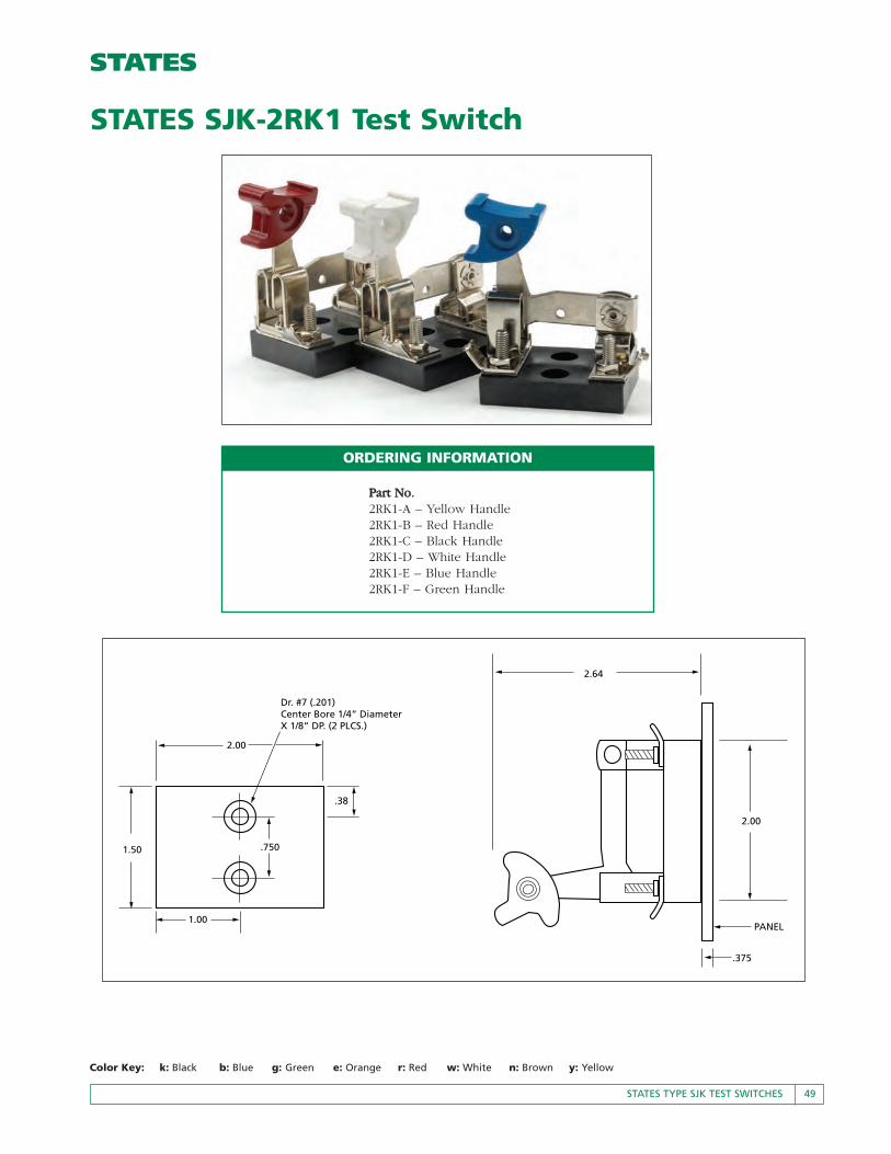
PPaarrtt NNoo..2RK1-A – Yellow Handle2RK1-B – Red Handle2RK1-C – Black Handle2RK1-D – White Handle2RK1-E – Blue Handle2RK1-F – Green Handle
STATES SJK-2RK1 Test Switch
2.00
2.00
2.64
PANEL
.38
.750
1.00
1.50
Dr. #7 (.201)Center Bore 1/4” DiameterX 1/8” DP. (2 PLCS.)
.375
ORDERING INFORMATION


