

7/17/2019 Uart Basics
http://slidepdf.com/reader/full/uart-basics 1/26
CONTENTS
• Introduction to UART
• Basics of Serial Communication -- RS-232
•Basic block diagram of UART
•Transmitter block of UART
• Receiver block
• Interfacing with PIC microcontroller
• Programming of UART
• Applications
1

7/17/2019 Uart Basics
http://slidepdf.com/reader/full/uart-basics 2/26
INTRODUCTION OF UART & USART
UART – Stands for Universal Asynchronous Receiver Transmitter
USART – Stands for Universal Synchronous Asynchronous Receiver Transmitter
In RS-232 we implement serial port with UART
Actually UART receives/sends data to microprocessor/microcontroller through data bus. The remaining part of signal handling of RS-232 is done by UART i.e. start bit,
stop bit, parity etc.
2

7/17/2019 Uart Basics
http://slidepdf.com/reader/full/uart-basics 3/26
A UART may be used when:
High speed is not required
An inexpensive communication link between two devices is required
UART communication is very cheapSingle wire for each direction (plus ground wire)
Asynchronous because no clock signal is transmitted
Relatively simple hardware
WHY USE A UART?
3
7/17/2019 Uart Basics
http://slidepdf.com/reader/full/uart-basics 4/26
4
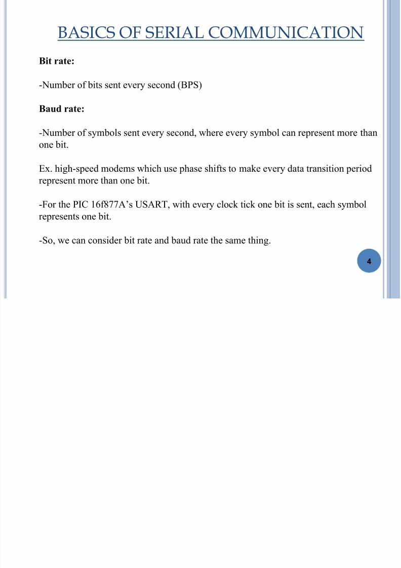
BASICS OF SERIAL COMMUNICATION
Bit rate:
-Number of bits sent every second (BPS)
Baud rate:
-Number of symbols sent every second, where every symbol can represent more than
one bit.
Ex. high-speed modems which use phase shifts to make every data transition period
represent more than one bit.
-For the PIC 16f877A‟s USART, with every clock tick one bit is sent, each symbol
represents one bit.
-So, we can consider bit rate and baud rate the same thing.

7/17/2019 Uart Basics
http://slidepdf.com/reader/full/uart-basics 5/26
5
TRANSMISSION REQUIREMENT
Before transmission begins, transmitter and receiver must agree
on :
- Baud rate (75, 150, 300, 600, etc)
- 1, 1.5 or 2 stop bits
- 5, 6, 7 or 8 data bits
- even, odd or no parity

7/17/2019 Uart Basics
http://slidepdf.com/reader/full/uart-basics 6/26
6
SERIAL COMMUNICATION BLOCK
DIAGRAM
Processor/
Controller
UART
Peripheral
RS-232
TransceiverMAX
232
6
PC

7/17/2019 Uart Basics
http://slidepdf.com/reader/full/uart-basics 7/26
7
EIA RS232C SERIAL INTERFACE STANDARD
• A “Space” (logic 0) will be between 3 and 25 volts.
• A “ Mark” (logic 1) will be between -3 and -25 volts.
• The region between 3 & -3 volts is undefined.
• Maximum data rates may be up to 20 kbps.
• Maximum serial cable length may be 15 meters.
• The reason to study RS-232C is that the serial part (Com port) found in PC‟S
uses this standard.
7/17/2019 Uart Basics
http://slidepdf.com/reader/full/uart-basics 8/26
8
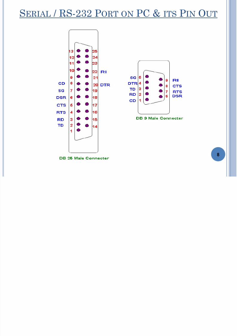
SERIAL / RS-232 PORT ON PC & ITS PIN OUT
7/17/2019 Uart Basics
http://slidepdf.com/reader/full/uart-basics 9/26
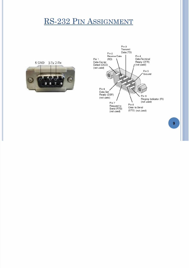
RS-232 PIN A SSIGNMENT
9

7/17/2019 Uart Basics
http://slidepdf.com/reader/full/uart-basics 10/26
10
FUNCTION OF VARIOUS PINS ON SERIAL PORT
Pin No. Pin Symbol Function
1 CD Carrier Detect: It is used by Modem to inform PC that it has detected Carrier on Phone
Line.2 RD Serial data is received on this line by PC.
3 TD Serial Data is transmitted on this pin by PC.
4 DTR Data Terminal Ready
When terminal (computer) powers up it asserts DTR high.
5 SG It is signal ground with reference to which voltages are interpreted as high or low.
6 DSR Data Set Ready.
When modem powers up it asserts DSR high.
7 RTS Request to Send.
Request to send is sent from (DTE) terminal (PC) to modem (DCE) to inform it that PC
wants to send some data to modem.
8 CTS Clear To Send.Upon received RTS from DTE (PC), the modem (DCE) asserts CTS high whenever it is
ready to receive data.
9 RI Ring Indicator.
It is set by modem to indicate the PC that a ringing signal has been detected on line.

7/17/2019 Uart Basics
http://slidepdf.com/reader/full/uart-basics 11/26
11
TTL 0/5 TO RS-232 -12/12
LEVEL CONVERSION

7/17/2019 Uart Basics
http://slidepdf.com/reader/full/uart-basics 12/26
12
BASIC BLOCK DIAGRAM OF UART

7/17/2019 Uart Basics
http://slidepdf.com/reader/full/uart-basics 13/26
UART/USART TRANSMITTER
13
1. The module is enabled by setting the TXEN bit.
2. Data to be sent should be written into the TXREG register. When using 9-bit,
TX9D must be written before writing TXREG.3. Byte will be immediately transferred to the shift register TSR after the STOP
bit from the pervious load is sent.
4. From there, data will be clocked out onto the TX pin preceded by a START
bit and followed by a STOP bit.

7/17/2019 Uart Basics
http://slidepdf.com/reader/full/uart-basics 14/26
TRANSMITTER CONTD.
TXIF bit : in the PIR1 register
Indicates when data can be written to TXREG(when data is moved from
TXREG into the Transmit Shift Register,
It cannot be cleared in software. It will reset only when new data is loaded
into the TXREG register.
It doesn‟t indicate that the transmission has completed.
TRMT bit:
Once the data in the TSR register has been clocked out on the TX pin(at the
beginning of the STOP bit), the TRMT bit in the TXSTA register will be set, Indicating that the transmission has been completed.
14

7/17/2019 Uart Basics
http://slidepdf.com/reader/full/uart-basics 15/26
UART/USART RECIEVER
15
1. The clock of the receiver is a multiple of the bit rate, in PIC 16f877A,it‟s x16
or x64. So, each bit is transmitted/received in 16 clock cycle.
2. If the receiver detects a start bit for a period= bit period (16 clock cycles),
then it waits for the period of half bit, and then sample the value on the RX
pin and shift it in the receiving shift register.

7/17/2019 Uart Basics
http://slidepdf.com/reader/full/uart-basics 16/26
RECEIVER CONTD.
3. Every received bit is sampled at the middle of the bit‟s time period.
4. The USART can be configured to receive eight or nine bits by the RX9 bit in the
RCSTA register.
5. After the detection of a START bit, eight or nine bits of serial data are shifted
from the RX pin into the Receive Shift Register, one bit at a time.
6. After the last bit has been shifted in, the STOP bit is checked and the data is
moved into the FIFO buffer.
7. RCREG is the output of the two element FIFO buffer. A next start bit can be sent
immediately after the stop bit.
8. RCIF: indicates when data is available in the RCREG.
16

7/17/2019 Uart Basics
http://slidepdf.com/reader/full/uart-basics 17/26
UART CHARACTER TRANSMISSION
Below is a timing diagram for the transmission of a single byte
Uses a single wire for transmission
Each block represents a bit that can be a mark (logic „1) or space (logic
„0‟)
Time
1 bit time
mark
space
17

7/17/2019 Uart Basics
http://slidepdf.com/reader/full/uart-basics 18/26
UART REGISTERS
To use and control the UART, special internal registers are assigned to them.
Usually there will be at least four registers: control, status, receive and transmitregisters. All these vary in size depending on the MCU.
1) Control Register - Contains settings for the UART. Some common
settings/features include: Number of data bits, number of stop bits, parity control,
UART TX/RX enable/disable, baud rate setting, RX/TX interrupt enable, etc.
2) Status Register - From its name, this contains information about the UART's
condition or state. During run-time, this register may be helpful in guiding the
processor on the next instruction to execute like when to retrieve data.
Information that can be retrieved include: data send/receive ready, etc.
3) Receive Register - This is the where received data is temporarily stored.
4) Transmit Register - A buffer register/s for temporarily storing data to be sent.
18

7/17/2019 Uart Basics
http://slidepdf.com/reader/full/uart-basics 19/26
UART INTERFACING
19
7/17/2019 Uart Basics
http://slidepdf.com/reader/full/uart-basics 20/26
UART ALTERNATIVES
Becoming much less common
Largely been replaced by faster, more sophisticated interfaces
PCs: USB (peripherals), Ethernet (networking)
Still used today when simple low speed communication is needed
20

7/17/2019 Uart Basics
http://slidepdf.com/reader/full/uart-basics 21/26
B ASIC PROGRAM FOR TRANSMITTING SERIALLY
Void main(void)
{TRISB=0; //initializing PORT B as an output
PORTB=0; // clearing out PORT B
SPBRG=51; // the hex value selected from the table
TXSTA=0B00100010; // determining the settings for the transmitter
RCSTA=0B10010000; // determining the settings for the receiver
TXREG=0X0; // intializing the binary valye of the transmitted information
do // beginning of the endless loop from ‘do’ to ’while(1)’
{
TXREG++; // increasing the TXREG by one
while(!TRMT); // waiting for a whole data frame to be ready for transmission
while(!RCIF); // waiting for a whole data frame to be received
PORTB=RCREG; // the received data is sent to PORT B
for(i=0;i<3000;i++) // delay in order to identify the change by looking at the LEDs
}
while(1);
}
21
7/17/2019 Uart Basics
http://slidepdf.com/reader/full/uart-basics 22/26
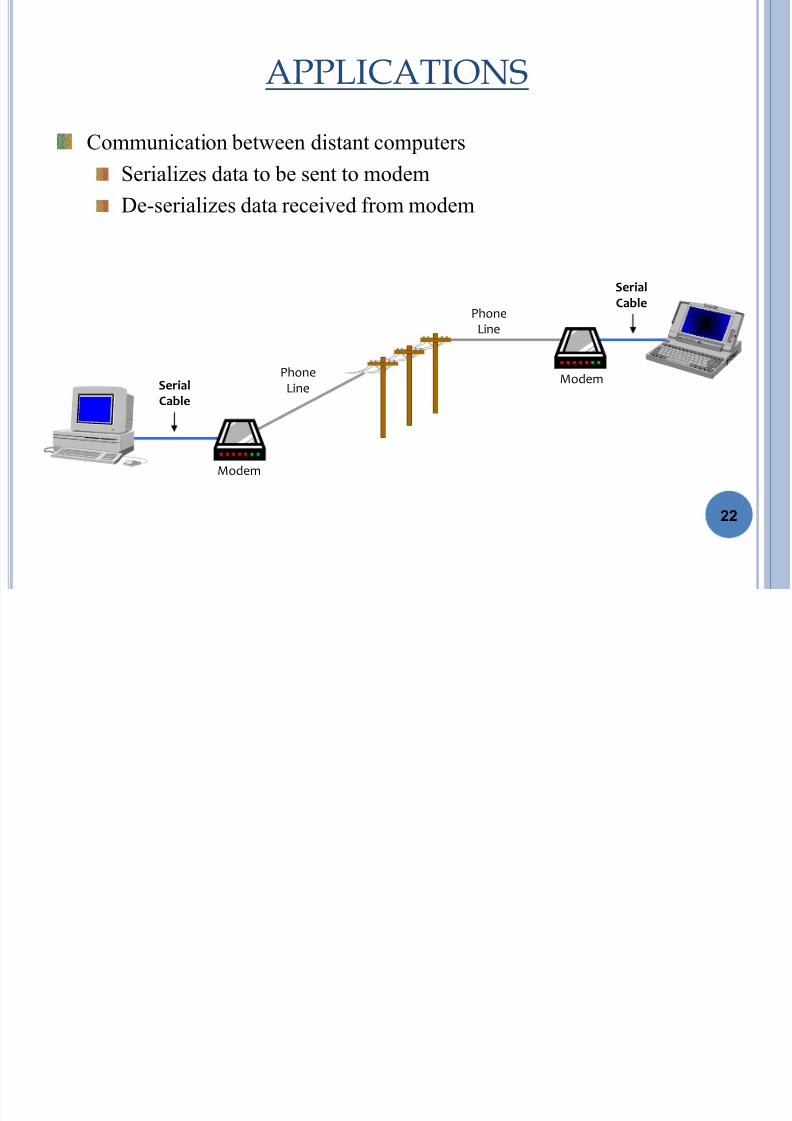
APPLICATIONS
Communication between distant computersSerializes data to be sent to modem
De-serializes data received from modem
Serial
Cable
Serial
CablePhone
Line
Phone
Line
Modem
Modem
22

7/17/2019 Uart Basics
http://slidepdf.com/reader/full/uart-basics 23/26
APPLICATIONS CONTD.
PC serial port is a UART!
Serializes data to be sent over serial cableDe-serializes received data
• The UART is also responsible for baud rate generation.
• This determines the speed at which data is transmitted and received. One baud is
one bit per second (bps).
• With modern UARTs, 230,400 baud can be achieved with a short cable length ofa few feet.
Serial
Cable
Serial
Cable
DeviceSerial
Port
Serial
Port
23

7/17/2019 Uart Basics
http://slidepdf.com/reader/full/uart-basics 24/26
SUMMARY
24
To make asynchronous connection using the PIC‟s USART:
• At the Transmitter end:
1. Determine the value of the SPBRG register and the BRGH-bit according to the
required baud rate.
2. The SYNC-bit [TXSTA<4>] is cleared, SPEN-bit [RCSTA<7>] is set to enable the
serial port.
3. On 9-bit data transmission, the TX9-bit [TXSTA<6>] is set.
4. TXEN-bit [TXSTA<5>] is set to enable data transmission.
5. On 9-bit data transmission, value of the ninth bit should be written to the TX9D-bit
[TXSTA<0>].
6. Transmission can be started again by writing 8-bit data to the TXREG register,
usually wait for at least (1ms) between every two writes.

7/17/2019 Uart Basics
http://slidepdf.com/reader/full/uart-basics 25/26
SUMMARY CONTD.
At the Receiver end:
1.Determine the value of the SPBRG register and the BRGH-bit according to the
required baud rate.
2.The SYNC-bit [TXSTA<4>] is cleared, SPEN-bit [RCSTA<7>] is set to enable the
serial port.
3.On 9-bit data receive, the RX9-bit [RCSTA<6>] is set.
4.Data receive should be enabled by setting the CREN-bit [RCSTA<4>].
5.The RCSTA register should be read to get information on possible errors which have
occurred during transmission.
6.On 9-bit data receive, the ninth bit will be stored in RX9D-bit [RCSTA<0>].
7.Received 8-bit data stored in the RCREG register should be read.25
7/17/2019 Uart Basics
http://slidepdf.com/reader/full/uart-basics 26/26
Naveen Kumar
Courtesy
26


