
UE Fading Test with the CMW500 RF Tester and the SMW200A
Application Note
Products:
ı R&S®CMW500
ı R&S®SMW200A
This application note shows how to perform user
equipment (UE) receiver tests, such as block error
rate (BLER) and throughput tests, under fading
conditions with the R&S®CMW500 RF tester and the
R&S®SMW200A vector signal generator in LTE(-A),
W-CDMA (HSPA+), TD-SCDMA, GSM (GRPS and
EGPRS(2)), CDMA2000 and 1xEV-DO.
Note:
Please find the most up-to-date document on our homepage
http:\\www.rohde-schwarz.com/appnote/1MA194.
Ber
nhar
d S
chul
z
10.2
015
- 1M
A19
4_3e
App
licat
ion
Not
e

Introduction
Dig IQ connectors at the CMW
1MA194_3e Rohde & Schwarz UE Fading Test with the CMW500 RF Tester and the SMW200A 2
Table of Contents
1 Introduction ......................................................................................... 5
2 Measurement Setup ............................................................................ 7
2.1.1 Fading Test Setup for One Baseband Signal ................................................................ 7
2.1.2 Fading Test Setup for Two Basebands Signals ............................................................ 8
2.1.3 Fading Test Setup for Four Basebands Signals ............................................................ 8
2.1.4 Fading Test Setup for more than four Basebands Signals ............................................ 9
2.2 Dig IQ connectors at the CMW ................................................................................... 9
2.3 SMW Configuration....................................................................................................10
2.3.1 System Configuration / MIMO Settings .......................................................................10
2.3.2 External Reference ......................................................................................................14
2.3.3 Digital input ..................................................................................................................15
2.3.4 Digital output ................................................................................................................16
2.3.5 Display settings (AMU only) .........................................................................................18
2.3.6 Fading settings .............................................................................................................18
2.3.7 AWGN settings ............................................................................................................22
2.3.8 Compensation of necessary attenuation .....................................................................23
3 LTE(-A) Measurements ..................................................................... 26
3.1 UE Receiver Measurement in LTE: Extended BLER ..............................................27
3.2 Scenarios for one cell ...............................................................................................29
3.2.1 “1 Cell – Fading – 1 RF Out” scenario (SISO) .............................................................29
3.2.2 “1 Cell – Fading – 2 RF Out” scenario (MIMO) ............................................................34
3.2.3 “1 Cell – Fading –MIMO 4x2 2 RF Out” scenario (4x2 MIMO) ....................................51
3.3 Scenarios for Carrier Aggregation ...........................................................................55
3.3.1 “2CC CA – Fading – 2 RF Out” scenario (CA with SISO) ...........................................55
3.3.2 “2CC CA – Fading – 4 RF Out” scenario (CA with MIMO) ..........................................60
3.4 Scenarios for Carrier Aggregation with CMWflexx ................................................64
3.4.1 “2CC CA – Fading – 4 RF Out Distributed” scenario (CA with MIMO) ........................64
3.4.2 “3CC CA – Fading – 6 RF Out” scenario (CA with 3 CC’s and MIMO) .......................65
3.4.3 “4CC CA – Fading – 8 RF Out” scenario (CA with 4 CC’s and MIMO) .......................69
3.5 CMW Internal Fading for LTE(-A) .............................................................................73
4 W-CDMA and HSPA(+) Measurements ............................................ 76
Introduction
Dig IQ connectors at the CMW
1MA194_3e Rohde & Schwarz UE Fading Test with the CMW500 RF Tester and the SMW200A 3
4.1 UE Receiver Measurement in W-CDMA: Rx Meas ..................................................77
4.2 SISO Configuration ....................................................................................................80
4.3 Rx Diversity Configuration (SIMO) ...........................................................................84
4.4 Dual-Carrier Configuration (DC-HSPA+) .................................................................87
4.5 DC-HSPA+ with Rx Diversity Configuration ............................................................91
4.6 Dual-Band HSDPA Configuration (DB-DC-HSPA+) ................................................94
4.7 Dual Band HSDPA with Rx Diversity Configuration (DB-DC-HSPA+ with Rx
Diversity) .....................................................................................................................99
4.8 CMW Internal Fading for W-CDMA and HSPA(+) ..................................................102
5 GSM and (E)GPRS(2) Measurements ............................................ 105
5.1 Mobile Station Receiver Measurement in GSM: Rx Meas ...................................108
5.2 Fading Scenario .......................................................................................................112
5.3 Fading with Hopping (single DL carrier) ...............................................................116
5.4 Fading with DL Dual Carrier ...................................................................................121
5.5 CMW Internal Fading for GSM and (E)GPRS(2) ....................................................122
6 TD-SCDMA Measurements ............................................................. 125
6.1 UE Receiver Measurement in TD-SCDMA: Rx Meas ............................................125
6.2 Fading Scenario .......................................................................................................126
7 CDMA2000 and 1xEV-DO Measurements ..................................... 129
7.1 CDMA2000 ................................................................................................................129
7.1.1 Mobile Station Receiver Measurement in CDMA2000: Rx Meas ..............................130
7.1.2 Fading Scenario .........................................................................................................133
7.1.3 CMW Internal Fading for CDMA2000 ........................................................................135
7.2 1xEV-DO ....................................................................................................................137
7.2.1 Access Terminal Receiver Measurement in 1xEV-DO: Rx Meas .............................138
7.2.2 Fading Scenario .........................................................................................................140
7.2.3 CMW Internal Fading for 1xEV-DO ...........................................................................143
8 Data Application Unit (DAU) .......................................................... 145
8.1 LTE ............................................................................................................................148
8.2 W-CDMA and with HSPA(+) ....................................................................................148
8.3 GSM and (E)GPRS(2) ...............................................................................................150
8.4 TD-SCDMA ................................................................................................................150
8.5 CDMA2000 and 1XEV-DO ........................................................................................151
9 Appendix ......................................................................................... 154

Introduction
Dig IQ connectors at the CMW
1MA194_3e Rohde & Schwarz UE Fading Test with the CMW500 RF Tester and the SMW200A 4
9.1 Literature ..................................................................................................................154
9.2 Additional Information ............................................................................................154
9.3 Ordering Information ...............................................................................................155
Introduction
Dig IQ connectors at the CMW
1MA194_3e Rohde & Schwarz UE Fading Test with the CMW500 RF Tester and the SMW200A 5
1 Introduction
The R&S®CMW500 wideband radio communication tester can be used throughout all
phases of UE device development. It supports different mobile standards, such as
LTE(-A) (FDD and TDD), W-CDMA (HSPA+, TD-SCDMA), GSM (including GPRS,
EDGE and EGPRS(2) and VAMOS), CDMA2000 and 1xEV-DO.
Testing under real propagation conditions is important for UE receiver sensitivity tests.
The measurement type depends on the mobile standard, e.g. a bit-error rate (BER) or
a block-error rate (BLER). The throughput can be calculated directly from the BLER.
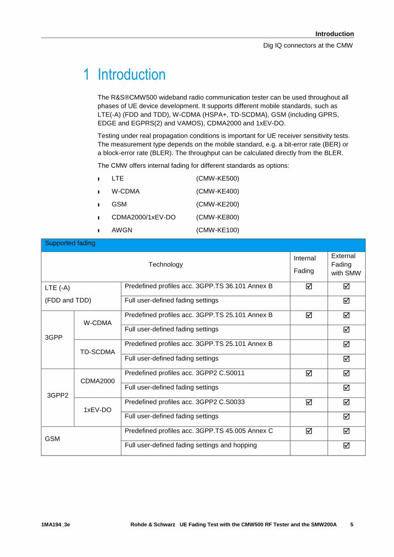
The CMW offers internal fading for different standards as options:
ı LTE (CMW-KE500)
ı W-CDMA (CMW-KE400)
ı GSM (CMW-KE200)
ı CDMA2000/1xEV-DO (CMW-KE800)
ı AWGN (CMW-KE100)
Supported fading
Technology Internal
Fading
External
Fading
with SMW
LTE (-A)
(FDD and TDD)
Predefined profiles acc. 3GPP.TS 36.101 Annex B
Full user-defined fading settings
3GPP
W-CDMA
Predefined profiles acc. 3GPP.TS 25.101 Annex B
Full user-defined fading settings
TD-SCDMA
Predefined profiles acc. 3GPP.TS 25.101 Annex B
Full user-defined fading settings
3GPP2
CDMA2000
Predefined profiles acc. 3GPP2 C.S0011
Full user-defined fading settings
1xEV-DO
Predefined profiles acc. 3GPP2 C.S0033
Full user-defined fading settings
GSM
Predefined profiles acc. 3GPP.TS 45.005 Annex C
Full user-defined fading settings and hopping

Introduction
Dig IQ connectors at the CMW
1MA194_3e Rohde & Schwarz UE Fading Test with the CMW500 RF Tester and the SMW200A 6
The combination of the CMW500 wideband radio communication tester as base station
simulator and the SMW200A vector signal generator offers full user-defined channel
simulation, including fading for SISO and MIMO scenarios, as well as noise.
This application note shows the test setups for external fading, explains the settings
required for the various measurement configurations, such as Rx diversity and MIMO
for LTE, W-CDMA, GSM and TD-SCDMA. In addition, it specifies the most important
remote commands along the way.
The CMW is able to perform fading internally with predefined fading profiles. This
application note also explains for every standard the internal fading settings briefly.
The AMU200A baseband and fading simulator can also be used to provide the external
fading. Please note that the here shown screenshots and settings apply for the
SMW200A. Possible differences are explained in the particular sections.
The following abbreviations are used in the following text for R&S® test equipment:
ı The R&S®CMW500 wideband radio communication tester is referred to as CMW.
ı The R&S®SMW200A vector signal generator is referred to as SMW.
ı The R&S®AMU200A fading simulator is referred to as AMU.
ı R&S® refers to Rohde & Schwarz GmbH und Co KG.
Measurement Setup
Dig IQ connectors at the CMW
1MA194_3e Rohde & Schwarz UE Fading Test with the CMW500 RF Tester and the SMW200A 7
2 Measurement Setup
This chapter deals with the measurement setup for external fading with the SMW. For
internal fading with the CMW only, no special setup is needed.
Fading and AWGN characteristics are applied in the SMW. To do this, it is necessary
to feed the CMW’s digital baseband signals through the SMW.
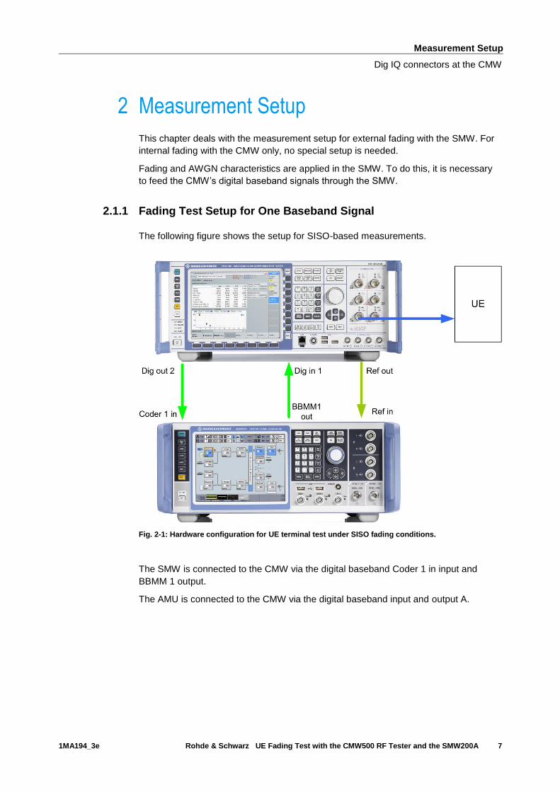
2.1.1 Fading Test Setup for One Baseband Signal
The following figure shows the setup for SISO-based measurements.
Fig. 2-1: Hardware configuration for UE terminal test under SISO fading conditions.
The SMW is connected to the CMW via the digital baseband Coder 1 in input and
BBMM 1 output.
The AMU is connected to the CMW via the digital baseband input and output A.
Measurement Setup
Dig IQ connectors at the CMW
1MA194_3e Rohde & Schwarz UE Fading Test with the CMW500 RF Tester and the SMW200A 8
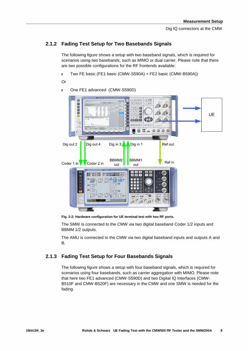
2.1.2 Fading Test Setup for Two Basebands Signals
The following figure shows a setup with two baseband signals, which is required for
scenarios using two basebands, such as MIMO or dual carrier. Please note that there
are two possible configurations for the RF frontends available:
ı Two FE basic (FE1 basic (CMW-S590A) + FE2 basic (CMW-B590A))
Or
ı One FE1 advanced (CMW-S590D)
Fig. 2-2: Hardware configuration for UE terminal test with two RF ports.
The SMW is connected to the CMW via two digital baseband Coder 1/2 inputs and
BBMM 1/2 outputs.
The AMU is connected to the CMW via two digital baseband inputs and outputs A and
B.
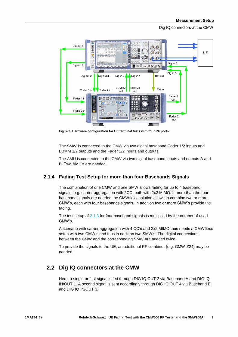
2.1.3 Fading Test Setup for Four Basebands Signals
The following figure shows a setup with four baseband signals, which is required for
scenarios using four basebands, such as carrier aggregation with MIMO. Please note
that here two FE1 advanced (CMW-S590D) and two Digital IQ Interfaces (CMW-
B510F and CMW-B520F) are necessary in the CMW and one SMW is needed for the
fading.
Measurement Setup
Dig IQ connectors at the CMW
1MA194_3e Rohde & Schwarz UE Fading Test with the CMW500 RF Tester and the SMW200A 9
Fig. 2-3: Hardware configuration for UE terminal tests with four RF ports.
The SMW is connected to the CMW via two digital baseband Coder 1/2 inputs and
BBMM 1/2 outputs and the Fader 1/2 inputs and outputs.
The AMU is connected to the CMW via two digital baseband inputs and outputs A and
B. Two AMU’s are needed.
2.1.4 Fading Test Setup for more than four Basebands Signals
The combination of one CMW and one SMW allows fading for up to 4 baseband
signals, e.g. carrier aggregation with 2CC, both with 2x2 MIMO. If more than the four
baseband signals are needed the CMWflexx solution allows to combine two or more
CMW’s, each with four basebands signals. In addition two or more SMW’s provide the
fading.
The test setup of 2.1.3 for four baseband signals is multiplied by the number of used
CMW’s.
A scenario with carrier aggregation with 4 CC’s and 2x2 MIMO thus needs a CMWflexx
setup with two CMW’s and thus in addition two SMW’s. The digital connections
between the CMW and the corresponding SMW are needed twice.
To provide the signals to the UE, an additional RF combiner (e.g. CMW-Z24) may be
needed.
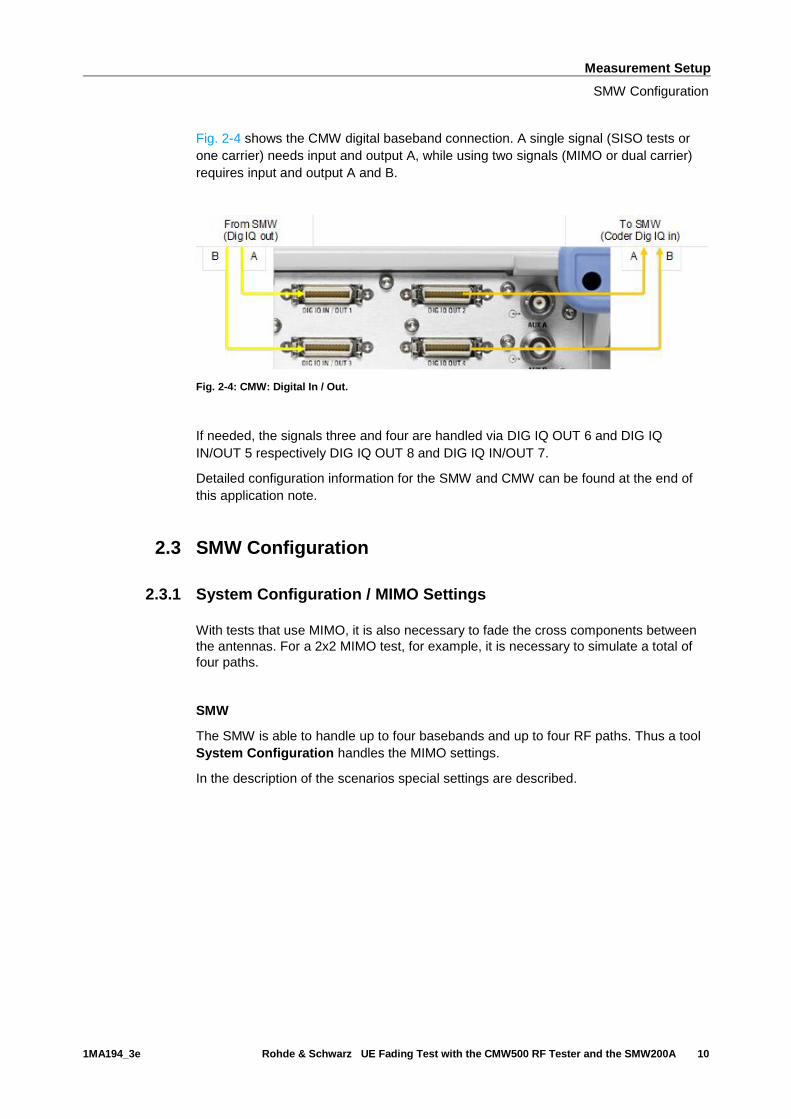
2.2 Dig IQ connectors at the CMW
Here, a single or first signal is fed through DIG IQ OUT 2 via Baseband A and DIG IQ
IN/OUT 1. A second signal is sent accordingly through DIG IQ OUT 4 via Baseband B
and DIG IQ IN/OUT 3.
Measurement Setup
SMW Configuration
1MA194_3e Rohde & Schwarz UE Fading Test with the CMW500 RF Tester and the SMW200A 10
Fig. 2-4 shows the CMW digital baseband connection. A single signal (SISO tests or
one carrier) needs input and output A, while using two signals (MIMO or dual carrier)
requires input and output A and B.
Fig. 2-4: CMW: Digital In / Out.
If needed, the signals three and four are handled via DIG IQ OUT 6 and DIG IQ
IN/OUT 5 respectively DIG IQ OUT 8 and DIG IQ IN/OUT 7.
Detailed configuration information for the SMW and CMW can be found at the end of
this application note.
2.3 SMW Configuration
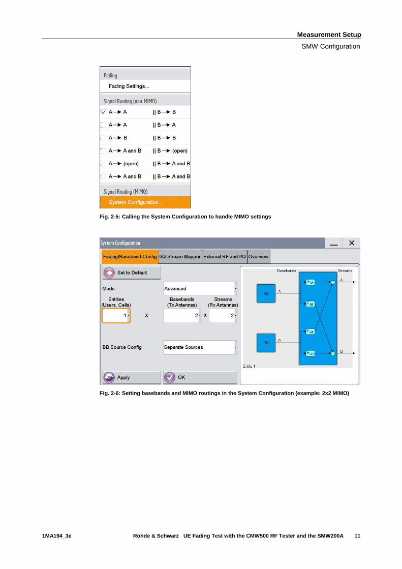
2.3.1 System Configuration / MIMO Settings
With tests that use MIMO, it is also necessary to fade the cross components between
the antennas. For a 2x2 MIMO test, for example, it is necessary to simulate a total of
four paths.
SMW
The SMW is able to handle up to four basebands and up to four RF paths. Thus a tool
System Configuration handles the MIMO settings.
In the description of the scenarios special settings are described.
Measurement Setup
SMW Configuration
1MA194_3e Rohde & Schwarz UE Fading Test with the CMW500 RF Tester and the SMW200A 11
Fig. 2-5: Calling the System Configuration to handle MIMO settings
Fig. 2-6: Setting basebands and MIMO routings in the System Configuration (example: 2x2 MIMO)
Measurement Setup
SMW Configuration
1MA194_3e Rohde & Schwarz UE Fading Test with the CMW500 RF Tester and the SMW200A 12
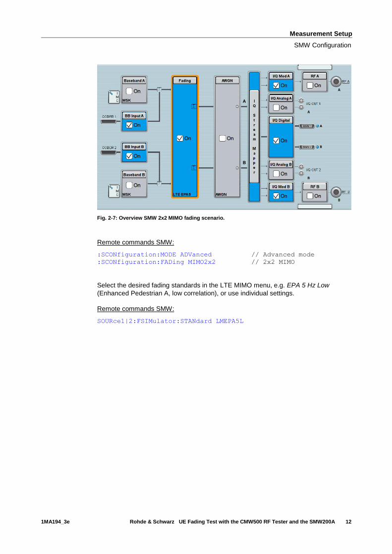
Fig. 2-7: Overview SMW 2x2 MIMO fading scenario.
Remote commands SMW:
:SCONfiguration:MODE ADVanced // Advanced mode
:SCONfiguration:FADing MIMO2x2 // 2x2 MIMO
Select the desired fading standards in the LTE MIMO menu, e.g. EPA 5 Hz Low
(Enhanced Pedestrian A, low correlation), or use individual settings.
Remote commands SMW:
SOURce1|2:FSIMulator:STANdard LMEPA5L

Measurement Setup
SMW Configuration
1MA194_3e Rohde & Schwarz UE Fading Test with the CMW500 RF Tester and the SMW200A 13
AMU
Select 2X2 MIMO in the Fading A (or B) config… menu.
Fig. 2-8: 2x2 MIMO scenario AMU
Remote commands AMU:
SOUR:FSIM:ROUT FA1A2BFB1A2BM24
Select the desired fading standards in the LTE MIMO menu, e.g. EPA 5 Hz Low
(Enhanced Pedestrian A, low correlation), or use individual settings.
Remote commands AMU:
SOURce1|2:FSIMulator:STANdard LMEPA5L
Measurement Setup
SMW Configuration
1MA194_3e Rohde & Schwarz UE Fading Test with the CMW500 RF Tester and the SMW200A 14
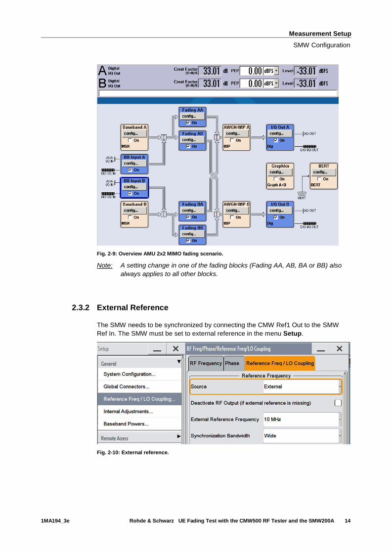
Fig. 2-9: Overview AMU 2x2 MIMO fading scenario.
Note: A setting change in one of the fading blocks (Fading AA, AB, BA or BB) also
always applies to all other blocks.
2.3.2 External Reference
The SMW needs to be synchronized by connecting the CMW Ref1 Out to the SMW
Ref In. The SMW must be set to external reference in the menu Setup.
Fig. 2-10: External reference.
Measurement Setup
SMW Configuration
1MA194_3e Rohde & Schwarz UE Fading Test with the CMW500 RF Tester and the SMW200A 15
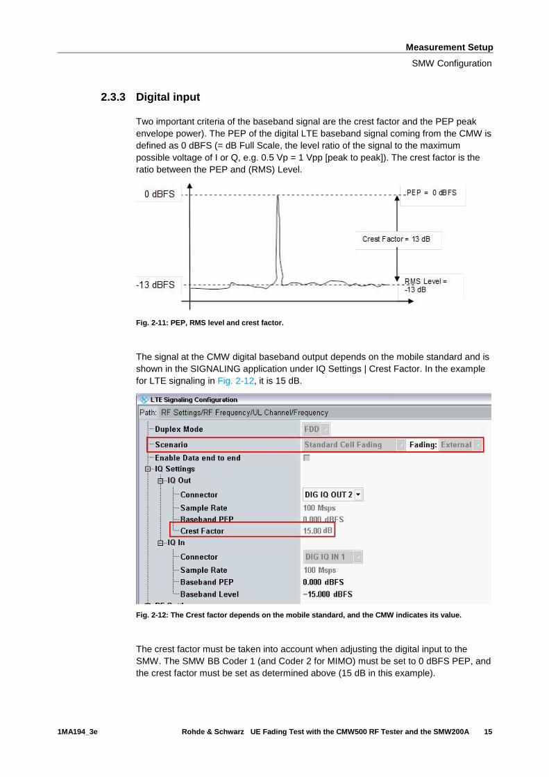
2.3.3 Digital input
Two important criteria of the baseband signal are the crest factor and the PEP peak
envelope power). The PEP of the digital LTE baseband signal coming from the CMW is
defined as 0 dBFS (= dB Full Scale, the level ratio of the signal to the maximum
possible voltage of I or Q, e.g. 0.5 Vp = 1 Vpp [peak to peak]). The crest factor is the
ratio between the PEP and (RMS) Level.
Fig. 2-11: PEP, RMS level and crest factor.
The signal at the CMW digital baseband output depends on the mobile standard and is
shown in the SIGNALING application under IQ Settings | Crest Factor. In the example
for LTE signaling in Fig. 2-12, it is 15 dB.
Fig. 2-12: The Crest factor depends on the mobile standard, and the CMW indicates its value.
The crest factor must be taken into account when adjusting the digital input to the
SMW. The SMW BB Coder 1 (and Coder 2 for MIMO) must be set to 0 dBFS PEP, and
the crest factor must be set as determined above (15 dB in this example).

Measurement Setup
SMW Configuration
1MA194_3e Rohde & Schwarz UE Fading Test with the CMW500 RF Tester and the SMW200A 16
Fig. 2-13: SMW Baseband Input Settings.
Remote commands SMW:
SOURce1|2:BBIN:DIGital:SOURce CODER1 // Select Coder 1
SOURce1|2:BBIN:STATe ON // Turn Input On
SOURce1|2:BBIN:MODE DIGital // Digital Input Mode
SOURce1|2:BBIN:SRATe:SOURce USER // Digital Input Mode
SOURce1|2:BBIN:SRAT 100MHz // 100 MHz sample rate
SOURce1|2:BBIN:CFACtor 15.00 // Set 15 dB Crest Factor
SOURce1|2:BBIN:POWer:PEAK 0.00 // Set 0 dBFS PEP
Remote commands AMU:
SOURce1|2:BBIN:STATe ON // Turn Baseband A|B Inp. ON
SOURce1|2:BBIN:MODE DIGital // Select Digital Input Mode
SOURce1|2:BBIN:SRATe:SOURce USER // Select Digital Input Mode
SOURce1|2:BBIN:SRAT 100MHz // 100 MHz sample rate
SOURce1|2:BBIN:CFACtor 15.00 // Set 15 dB Crest Factor
SOURce1|2:BBIN:POWer:PEAK 0.00 // Set 0 dBFS PEP
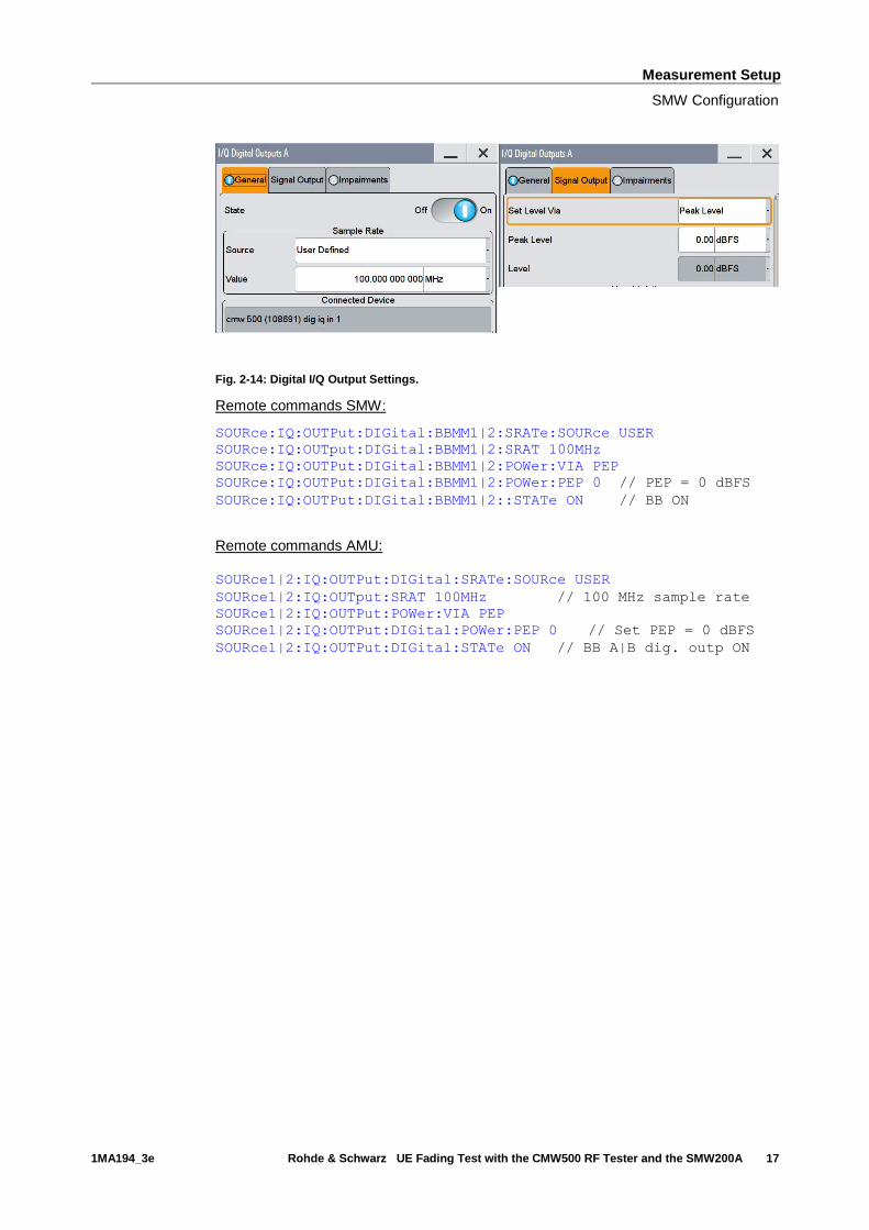
2.3.4 Digital output
The digital I/Q output BBMM1 (and BBMM2 for MIMO; A and B for the AMU) must be
turned ON, and the PEP must be set to the same value as at the input (0.00 dBFS).
Set the output sample rate to 100 MHz.
Measurement Setup
SMW Configuration
1MA194_3e Rohde & Schwarz UE Fading Test with the CMW500 RF Tester and the SMW200A 17
Fig. 2-14: Digital I/Q Output Settings.
Remote commands SMW:
SOURce:IQ:OUTPut:DIGital:BBMM1|2:SRATe:SOURce USER
SOURce:IQ:OUTput:DIGital:BBMM1|2:SRAT 100MHz
SOURce:IQ:OUTPut:DIGital:BBMM1|2:POWer:VIA PEP
SOURce:IQ:OUTPut:DIGital:BBMM1|2:POWer:PEP 0 // PEP = 0 dBFS
SOURce:IQ:OUTPut:DIGital:BBMM1|2::STATe ON // BB ON
Remote commands AMU:
SOURce1|2:IQ:OUTPut:DIGital:SRATe:SOURce USER
SOURce1|2:IQ:OUTput:SRAT 100MHz // 100 MHz sample rate
SOURce1|2:IQ:OUTPut:POWer:VIA PEP
SOURce1|2:IQ:OUTPut:DIGital:POWer:PEP 0 // Set PEP = 0 dBFS
SOURce1|2:IQ:OUTPut:DIGital:STATe ON // BB A|B dig. outp ON
Measurement Setup
SMW Configuration
1MA194_3e Rohde & Schwarz UE Fading Test with the CMW500 RF Tester and the SMW200A 18
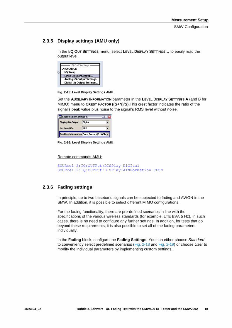
2.3.5 Display settings (AMU only)
In the I/Q OUT SETTINGS menu, select LEVEL DISPLAY SETTINGS… to easily read the
output level.
Fig. 2-15: Level Display Settings AMU
Set the AUXILIARY INFORMATION parameter in the LEVEL DISPLAY SETTINGS A (and B for
MIMO) menu to CREST FACTOR ((S+N)/S).This crest factor indicates the ratio of the
signal’s peak value plus noise to the signal’s RMS level without noise.
Fig. 2-16: Level Display Settings AMU
Remote commands AMU: SOURce1|2:IQ:OUTPut:DISPlay DIGItal
SOURce1|2:IQ:OUTPut:DISPlay:AINFormation CFSN
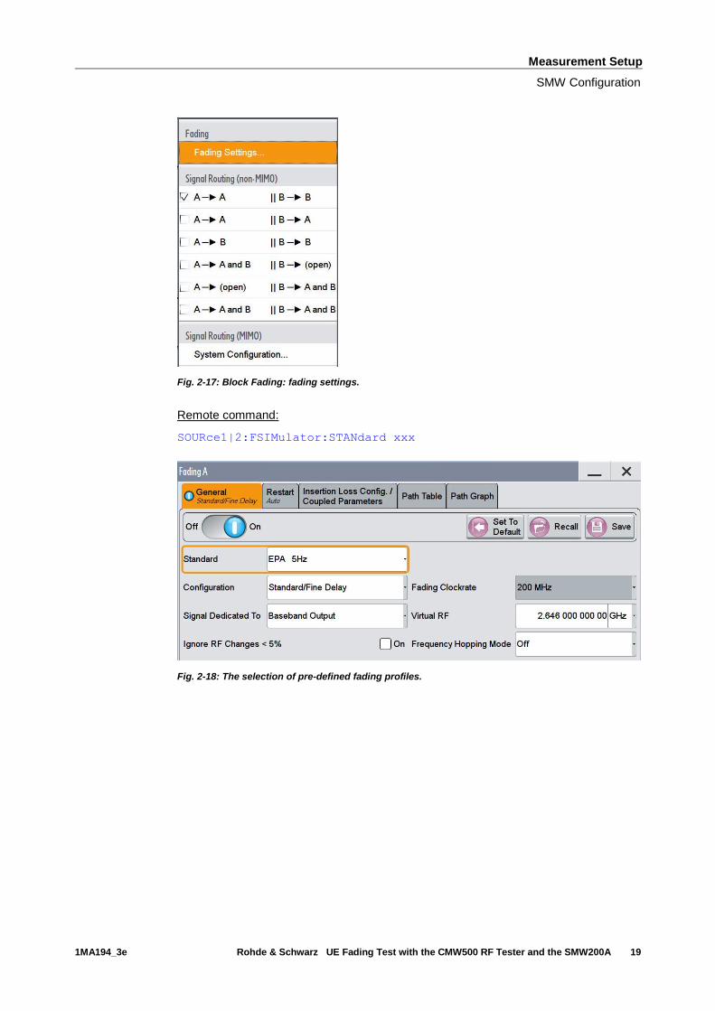
2.3.6 Fading settings
In principle, up to two baseband signals can be subjected to fading and AWGN in the
SMW. In addition, it is possible to select different MIMO configurations.
For the fading functionality, there are pre-defined scenarios in line with the
specifications of the various wireless standards (for example, LTE EVA 5 Hz). In such
cases, there is no need to configure any further settings. In addition, for tests that go
beyond these requirements, it is also possible to set all of the fading parameters
individually.
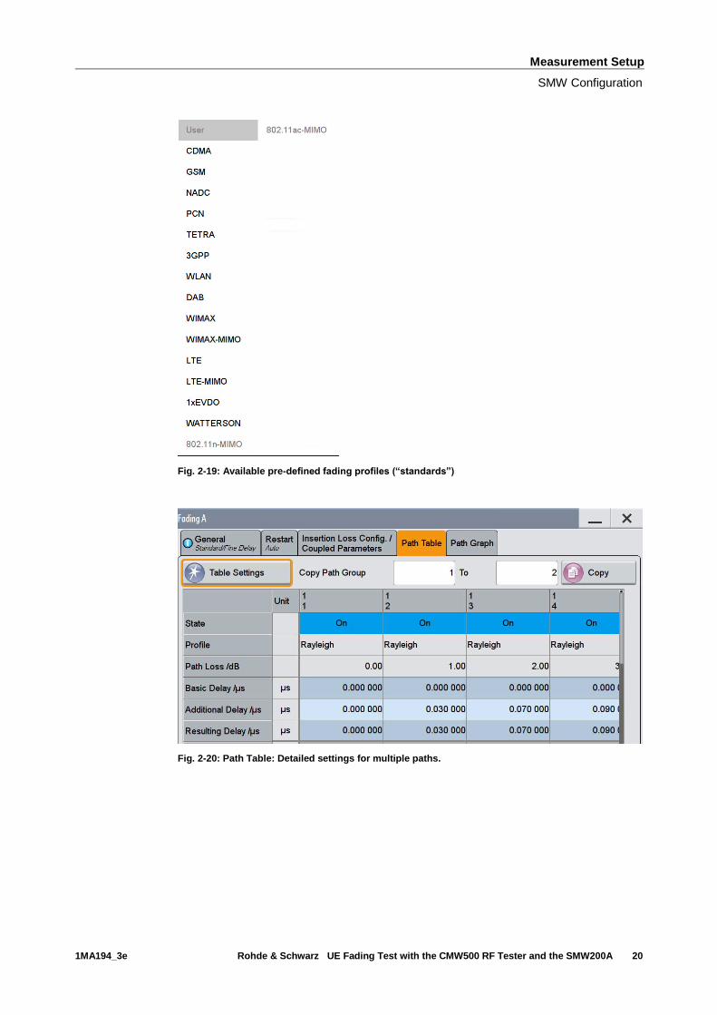
In the Fading block, configure the Fading Settings. You can either choose Standard
to conveniently select predefined scenarios (Fig. 2-18 and Fig. 2-19) or choose User to
modify the individual parameters by implementing custom settings.
Measurement Setup
SMW Configuration
1MA194_3e Rohde & Schwarz UE Fading Test with the CMW500 RF Tester and the SMW200A 19
Fig. 2-17: Block Fading: fading settings.
Remote command:
SOURce1|2:FSIMulator:STANdard xxx
Fig. 2-18: The selection of pre-defined fading profiles.
Measurement Setup
SMW Configuration
1MA194_3e Rohde & Schwarz UE Fading Test with the CMW500 RF Tester and the SMW200A 20
Fig. 2-19: Available pre-defined fading profiles (“standards”)
Fig. 2-20: Path Table: Detailed settings for multiple paths.
Measurement Setup
SMW Configuration
1MA194_3e Rohde & Schwarz UE Fading Test with the CMW500 RF Tester and the SMW200A 21
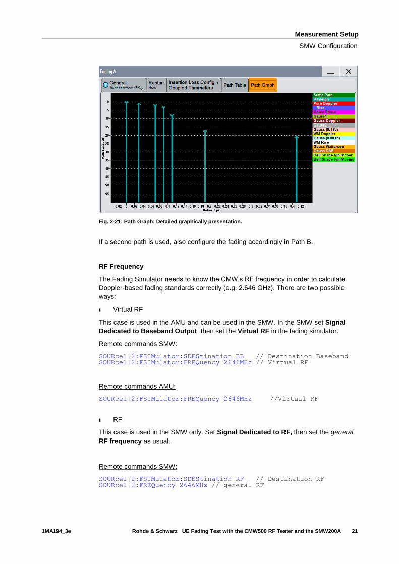
Fig. 2-21: Path Graph: Detailed graphically presentation.
If a second path is used, also configure the fading accordingly in Path B.
RF Frequency
The Fading Simulator needs to know the CMW’s RF frequency in order to calculate
Doppler-based fading standards correctly (e.g. 2.646 GHz). There are two possible
ways:
ı Virtual RF
This case is used in the AMU and can be used in the SMW. In the SMW set Signal
Dedicated to Baseband Output, then set the Virtual RF in the fading simulator.
Remote commands SMW:
SOURce1|2:FSIMulator:SDEStination BB // Destination Baseband SOURce1|2:FSIMulator:FREQuency 2646MHz // Virtual RF
Remote commands AMU:
SOURce1|2:FSIMulator:FREQuency 2646MHz //Virtual RF
ı RF
This case is used in the SMW only. Set Signal Dedicated to RF, then set the general
RF frequency as usual.
Remote commands SMW:
SOURce1|2:FSIMulator:SDEStination RF // Destination RF SOURce1|2:FREQuency 2646MHz // general RF

Measurement Setup
SMW Configuration
1MA194_3e Rohde & Schwarz UE Fading Test with the CMW500 RF Tester and the SMW200A 22
Enable Fading
Turn fading ON.
Remote command:
SOURce1|2:FSIMulator:STATe ON
2.3.7 AWGN settings
Click on AWGN in the AWGN block.
In the AWGN menu, set the System Bandwidth (e.g. 10 MHz), the desired Signal/Noise
Ratio (e.g. 0.00 dB) and turn the State ON.
Fig. 2-22: AWGN settings general
Fig. 2-23: AWGN settings power
Measurement Setup
SMW Configuration
1MA194_3e Rohde & Schwarz UE Fading Test with the CMW500 RF Tester and the SMW200A 23
Remote commands:
SOURce1|2:AWGN:MODE ADD // Additive noise
SOURce1|2:AWGN:BWID 10 MHz // bandwidth
SOURce1|2:AWGN:BWID:RAT 1.0 // bandwidth SOURce1|2:AWGN:POWer:MODE SN // Power mode signal to noise
SOURce1|2:AWGN:SNR 0.0 dB // SNR
SOURce1|2:AWGN ON // switch ON
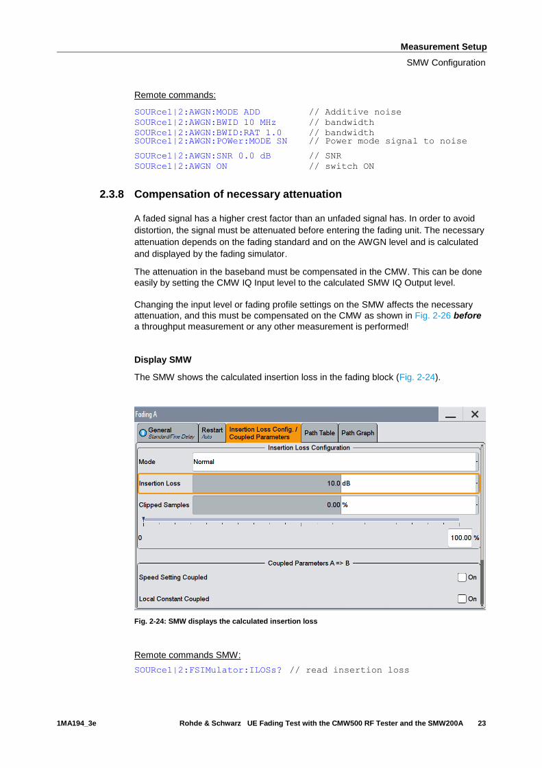
2.3.8 Compensation of necessary attenuation
A faded signal has a higher crest factor than an unfaded signal has. In order to avoid
distortion, the signal must be attenuated before entering the fading unit. The necessary
attenuation depends on the fading standard and on the AWGN level and is calculated
and displayed by the fading simulator.
The attenuation in the baseband must be compensated in the CMW. This can be done
easily by setting the CMW IQ Input level to the calculated SMW IQ Output level.
Changing the input level or fading profile settings on the SMW affects the necessary
attenuation, and this must be compensated on the CMW as shown in Fig. 2-26 before
a throughput measurement or any other measurement is performed!
Display SMW
The SMW shows the calculated insertion loss in the fading block (Fig. 2-24).
Fig. 2-24: SMW displays the calculated insertion loss
Remote commands SMW:
SOURce1|2:FSIMulator:ILOSs? // read insertion loss

Measurement Setup
SMW Configuration
1MA194_3e Rohde & Schwarz UE Fading Test with the CMW500 RF Tester and the SMW200A 24
The complete baseband level to be entered in the CMW calculates via:
Level BB out SMW= Crest Factor In SMW – Insertion Loss
In our example:
Level BB out SMW = -15 dB – 10 dB = -25 dBFS
Display AMU
The AMU shows the calculated level in the main screen directly (Fig. 2-25)(for the
Display configuration see 2.3.5).
Fig. 2-25: AMU settings for SISO fading. The displayed level has to be entered in the CMW.
Remote commands AMU:
SOURce1|2:IQ:OUTPut:DIGital:POWer:LEVel? // read level
Measurement Setup
SMW Configuration
1MA194_3e Rohde & Schwarz UE Fading Test with the CMW500 RF Tester and the SMW200A 25
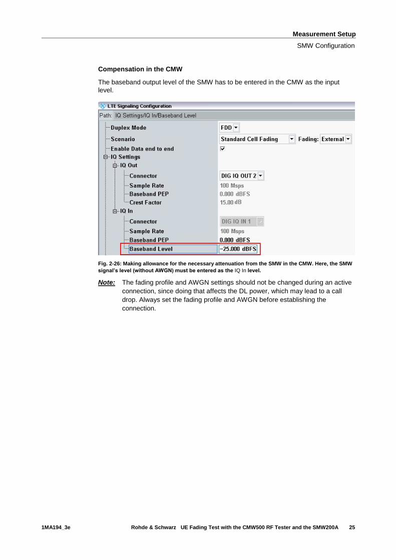
Compensation in the CMW
The baseband output level of the SMW has to be entered in the CMW as the input
level.
Fig. 2-26: Making allowance for the necessary attenuation from the SMW in the CMW. Here, the SMW
signal’s level (without AWGN) must be entered as the IQ In level.
Note: The fading profile and AWGN settings should not be changed during an active
connection, since doing that affects the DL power, which may lead to a call
drop. Always set the fading profile and AWGN before establishing the
connection.
LTE(-A) Measurements
SMW Configuration
1MA194_3e Rohde & Schwarz UE Fading Test with the CMW500 RF Tester and the SMW200A 26
3 LTE(-A) Measurements
The CMW supports both FDD and TDD (TD-LTE) duplexing modes.
With the LTE standard, the UE receiver measurements include BLER, throughput and
channel quality index (CQI). All measurements are summarized in the Extended
BLER measurement application (see 3.1).
Before starting the LTE signaling, external fading must be selected as the scenario.
Once signaling has begun, or once a connection has been established with the DUT, it
is no longer possible to change scenarios.
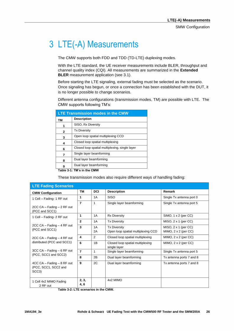
Different antenna configurations (transmission modes, TM) are possible with LTE. The
CMW supports following TM’s:
LTE Transmission modes in the CMW
TM Description
1 SISO, Rx Diversity
2 Tx Diversity
3 Open loop spatial multiplexing CCD
4 Closed loop spatial multiplexing
6 Closed loop spatial multiplexing, single layer
7 Single layer beamforming
8 Dual layer beamforming
9 Dual layer beamforming
Table 3-1: TM’s in the CMW
These transmission modes also require different ways of handling fading:
LTE Fading Scenarios
CMW Configuration TM DCI Description Remark
1 Cell – Fading- 1 RF out
2CC CA – Fading – 2 RF out
(PCC and SCC1)
1 1A SISO Single Tx antenna port 0
7 1 Single layer beamforming Single Tx antenna port 5
1 Cell – Fading- 2 RF out
2CC CA – Fading – 4 RF out
(PCC and SCC1)
2CC CA – Fading – 4 RF out
distributed (PCC and SCC1)
3CC CA – Fading – 6 RF out
(PCC, SCC1 and SCC2)
4CC CA – Fading – 8 RF out
(PCC, SCC1, SCC2 and
SCC3)
1 1A Rx Diversity SIMO, 1 x 2 (per CC)
2 1A Tx Diversity MISO, 2 x 1 (per CC)
3 1A
2A
Tx Diversity
Open loop spatial multiplexing CCD
MISO, 2 x 1 (per CC)
MIMO, 2 x 2 (per CC)
4 2 Closed loop spatial multiplexing MIMO, 2 x 2 (per CC)
6 1B Closed loop spatial multiplexing
single layer
MIMO, 2 x 2 (per CC)
7 1 Single layer beamforming Single Tx antenna port 5
8 2B Dual layer beamforming Tx antenna ports 7 and 8
9 2C Dual layer beamforming Tx antenna ports 7 and 8
1 Cell 4x2 MIMO Fading
2 RF out
2, 3,
4, 6
4x2 MIMO
Table 3-2: LTE scenarios in the CMW.
LTE(-A) Measurements
UE Receiver Measurement in LTE: Extended BLER
1MA194_3e Rohde & Schwarz UE Fading Test with the CMW500 RF Tester and the SMW200A 27
This section describes the necessary steps to perform an LTE Rx measurement under
several conditions, such as SISO or 2x2 MIMO fading.
For further information on LTE signaling and extended BLER measurements, refer to
[5].
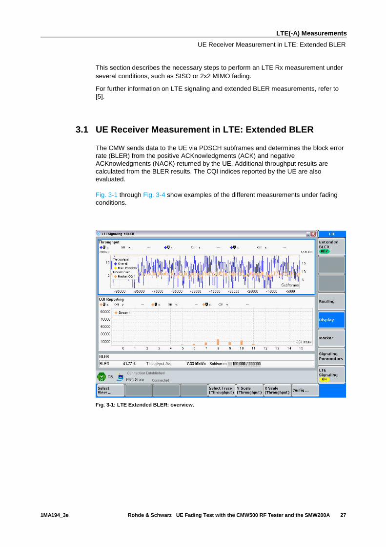
3.1 UE Receiver Measurement in LTE: Extended BLER
The CMW sends data to the UE via PDSCH subframes and determines the block error
rate (BLER) from the positive ACKnowledgments (ACK) and negative
ACKnowledgments (NACK) returned by the UE. Additional throughput results are
calculated from the BLER results. The CQI indices reported by the UE are also
evaluated.
Fig. 3-1 through Fig. 3-4 show examples of the different measurements under fading
conditions.
Fig. 3-1: LTE Extended BLER: overview.

LTE(-A) Measurements
UE Receiver Measurement in LTE: Extended BLER
1MA194_3e Rohde & Schwarz UE Fading Test with the CMW500 RF Tester and the SMW200A 28
Fig. 3-2: LTE Extended BLER: Throughput
Fig. 3-3: LTE Extended BLER: BLER
LTE(-A) Measurements
Scenarios for one cell
1MA194_3e Rohde & Schwarz UE Fading Test with the CMW500 RF Tester and the SMW200A 29
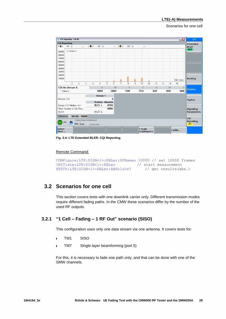
Fig. 3-4: LTE Extended BLER: CQI Reporting
Remote Command:
CONFigure:LTE:SIGN<i>:EBLer:SFRames 10000 // set 10000 frames
INITiate:LTE:SIGN<i>:EBLer // start measurement
FETCh:LTE:SIGN<i>:EBLer:ABSolute? // get results(abs.)
3.2 Scenarios for one cell
This section covers tests with one downlink carrier only. Different transmission modes
require different fading paths. In the CMW these scenarios differ by the number of the
used RF outputs.
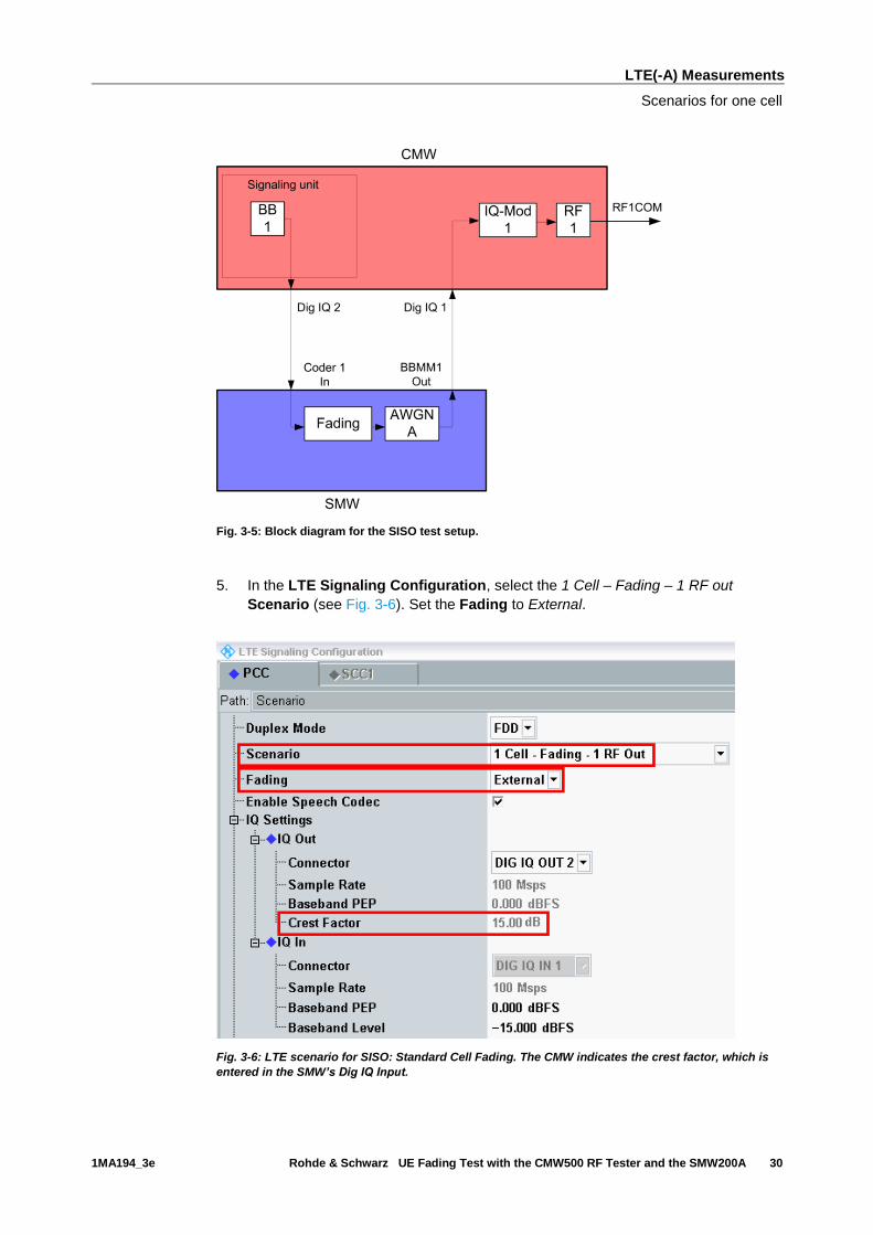
3.2.1 “1 Cell – Fading – 1 RF Out” scenario (SISO)
This configuration uses only one data stream via one antenna. It covers tests for:
ı TM1 SISO
ı TM7 Single layer beamforming (port 5)
For this, it is necessary to fade one path only, and that can be done with one of the
SMW channels.
LTE(-A) Measurements
Scenarios for one cell
1MA194_3e Rohde & Schwarz UE Fading Test with the CMW500 RF Tester and the SMW200A 30
Fig. 3-5: Block diagram for the SISO test setup.
5. In the LTE Signaling Configuration, select the 1 Cell – Fading – 1 RF out
Scenario (see Fig. 3-6). Set the Fading to External.
Fig. 3-6: LTE scenario for SISO: Standard Cell Fading. The CMW indicates the crest factor, which is
entered in the SMW’s Dig IQ Input.
LTE(-A) Measurements
Scenarios for one cell
1MA194_3e Rohde & Schwarz UE Fading Test with the CMW500 RF Tester and the SMW200A 31
Remote commands:
// 1 Cell–Fading– 1 RF Out external via RF2COM and IQ2 Out
ROUTe:LTE:SIGN:SCENario:SCFading RF2C,RX1,RF2C,TX1,IQ2O
// read out information of IQ settings
SENSe:LTE:SIGN<i>:IQOut:PATH<n>?
6. Take note of the Crest Factor under IQ Out and enter this value in the SMW
under Baseband Input Level (see Fig. 2-13 in section 2.3).
7. Set a fading and switch on I/Q Out (BBMM1)(see section 2.3).
8. In the CMW, enter the corresponding baseband level (Level BB out SMW= Crest
Factor In SMW – Insertion Loss; example: -15 dB – 10 dB = -25 dBFS, see 2.3.8 ),
which is indicated by the SMW (see Fig. 3-9). If you add noise to the signal, note
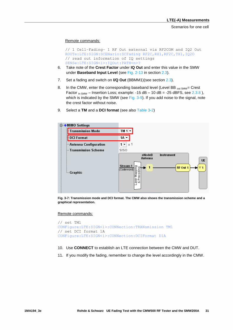
the crest factor without noise.
9. Select a TM and a DCI format (see also Table 3-2)
Fig. 3-7: Transmission mode and DCI format. The CMW also shows the transmission scheme and a
graphical representation.
Remote commands:
// set TM1
CONFigure:LTE:SIGN<i>:CONNection:TRANsmission TM1
// set DCI format 1A
CONFigure:LTE:SIGN<i>:CONNection:DCIFormat D1A
10. Use CONNECT to establish an LTE connection between the CMW and DUT.
11. If you modify the fading, remember to change the level accordingly in the CMW.

LTE(-A) Measurements
Scenarios for one cell
1MA194_3e Rohde & Schwarz UE Fading Test with the CMW500 RF Tester and the SMW200A 32
Fig. 3-8: Overview SMW settings for SISO fading.
Fig. 3-9: The SMW shows the necessary insertion loss (example: 10 dB)

LTE(-A) Measurements
Scenarios for one cell
1MA194_3e Rohde & Schwarz UE Fading Test with the CMW500 RF Tester and the SMW200A 33
Fig. 3-10: Making allowance for the necessary attenuation in the CMW. Here, the digital output level
of the SMW signal is entered as the IQ In level.
Remote command:
// set IQ In to PEP 0 dBFS and Level -25 dBFS
CONFigure:LTE:SIGN<i>:IQIN:PATH<n> 0.0, -25.0
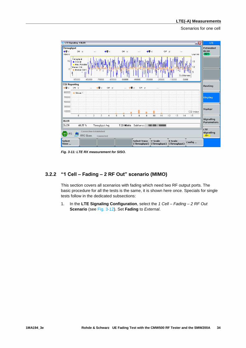
12. Start the RX measurement using Extended BLER (see section 3.1). Fig. 3-11
shows an example of an SISO measurement in the overview.
LTE(-A) Measurements
Scenarios for one cell
1MA194_3e Rohde & Schwarz UE Fading Test with the CMW500 RF Tester and the SMW200A 34
Fig. 3-11: LTE RX measurement for SISO.
3.2.2 “1 Cell – Fading – 2 RF Out” scenario (MIMO)
This section covers all scenarios with fading which need two RF output ports. The
basic procedure for all the tests is the same, it is shown here once. Specials for single
tests follow in the dedicated subsections:
1. In the LTE Signaling Configuration, select the 1 Cell – Fading – 2 RF Out
Scenario (see Fig. 3-12). Set Fading to External.
LTE(-A) Measurements
Scenarios for one cell
1MA194_3e Rohde & Schwarz UE Fading Test with the CMW500 RF Tester and the SMW200A 35
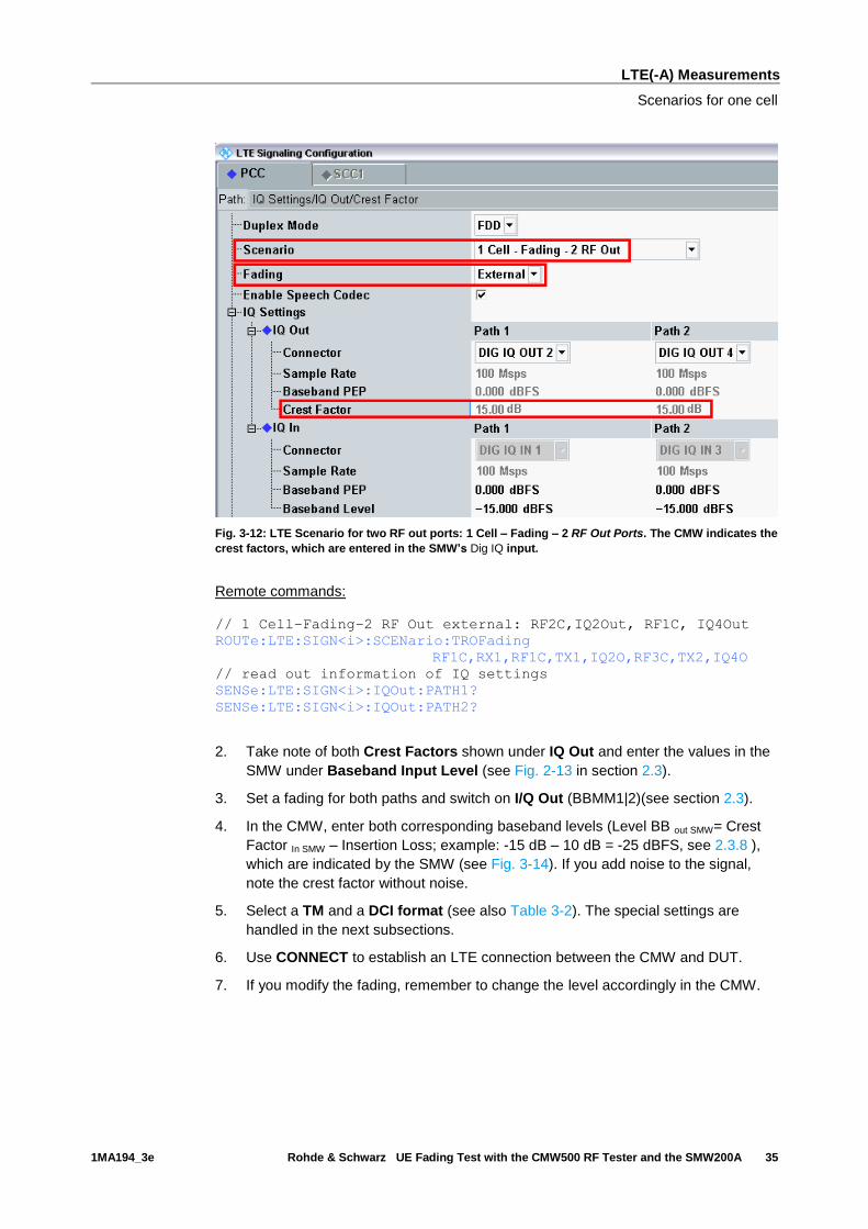
Fig. 3-12: LTE Scenario for two RF out ports: 1 Cell – Fading – 2 RF Out Ports. The CMW indicates the
crest factors, which are entered in the SMW’s Dig IQ input.
Remote commands:
// 1 Cell–Fading–2 RF Out external: RF2C,IQ2Out, RF1C, IQ4Out
ROUTe:LTE:SIGN<i>:SCENario:TROFading
RF1C,RX1,RF1C,TX1,IQ2O,RF3C,TX2,IQ4O
// read out information of IQ settings
SENSe:LTE:SIGN<i>:IQOut:PATH1?
SENSe:LTE:SIGN<i>:IQOut:PATH2?
2. Take note of both Crest Factors shown under IQ Out and enter the values in the
SMW under Baseband Input Level (see Fig. 2-13 in section 2.3).
3. Set a fading for both paths and switch on I/Q Out (BBMM1|2)(see section 2.3).
4. In the CMW, enter both corresponding baseband levels (Level BB out SMW= Crest
Factor In SMW – Insertion Loss; example: -15 dB – 10 dB = -25 dBFS, see 2.3.8 ),
which are indicated by the SMW (see Fig. 3-14). If you add noise to the signal,
note the crest factor without noise.
5. Select a TM and a DCI format (see also Table 3-2). The special settings are
handled in the next subsections.
6. Use CONNECT to establish an LTE connection between the CMW and DUT.
7. If you modify the fading, remember to change the level accordingly in the CMW.

LTE(-A) Measurements
Scenarios for one cell
1MA194_3e Rohde & Schwarz UE Fading Test with the CMW500 RF Tester and the SMW200A 36
Fig. 3-13: The SMW shows the necessary insertion loss (example: 10 dB)
Fig. 3-14: Compensating for the necessary attenuation in the CMW. Here, the levels of the SMW
signals are entered as the IQ IN levels.
Remote commands:
// set IQ In to PEP 0 dBFS and Level -25 dBFS
CONFigure:LTE:SIGN<i>:IQIN:PATH1 0.0, -25.0
CONFigure:LTE:SIGN<i>:IQIN:PATH2 0.0, -25.0
8. Start the RX measurement using Extended BLER (see section 3.1)
LTE(-A) Measurements
Scenarios for one cell
1MA194_3e Rohde & Schwarz UE Fading Test with the CMW500 RF Tester and the SMW200A 37
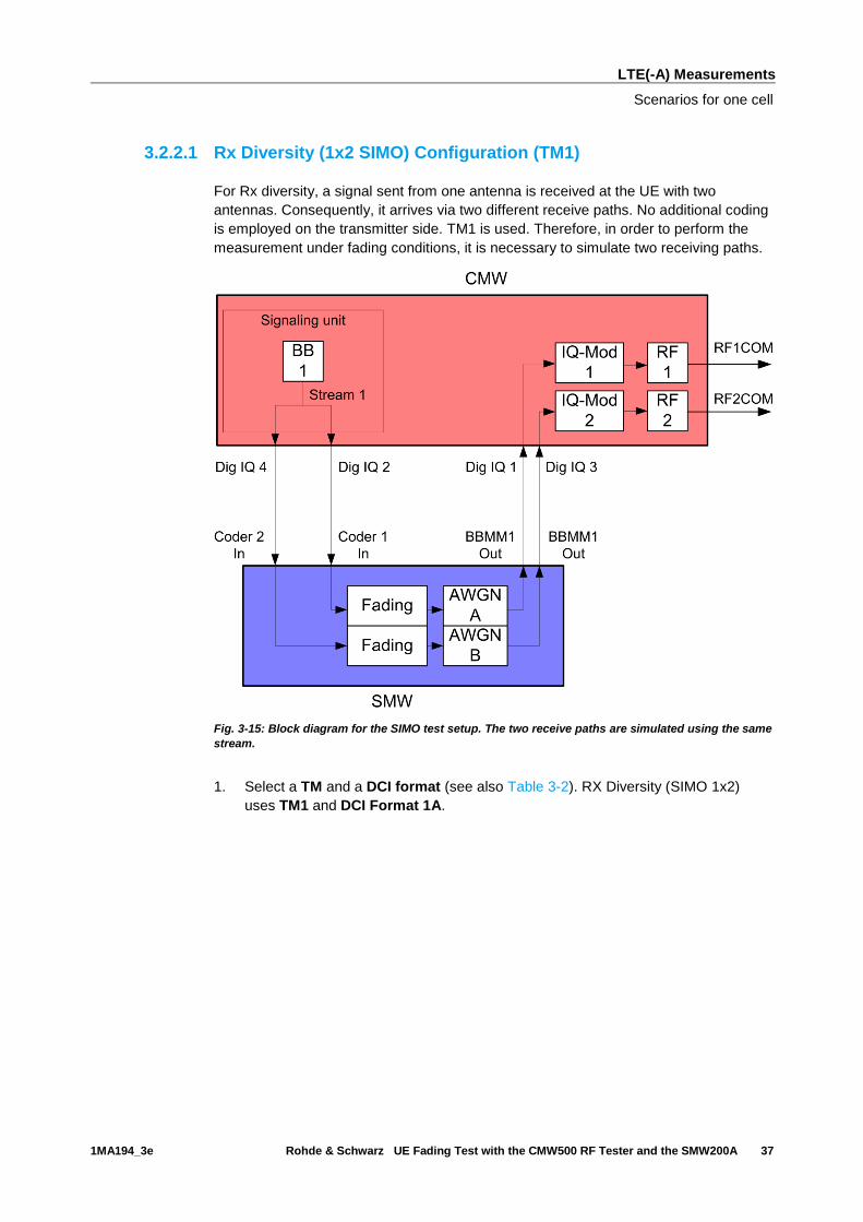
3.2.2.1 Rx Diversity (1x2 SIMO) Configuration (TM1)
For Rx diversity, a signal sent from one antenna is received at the UE with two
antennas. Consequently, it arrives via two different receive paths. No additional coding
is employed on the transmitter side. TM1 is used. Therefore, in order to perform the
measurement under fading conditions, it is necessary to simulate two receiving paths.
Fig. 3-15: Block diagram for the SIMO test setup. The two receive paths are simulated using the same
stream.
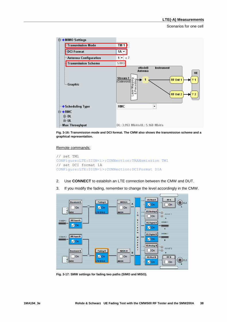
1. Select a TM and a DCI format (see also Table 3-2). RX Diversity (SIMO 1x2)
uses TM1 and DCI Format 1A.
LTE(-A) Measurements
Scenarios for one cell
1MA194_3e Rohde & Schwarz UE Fading Test with the CMW500 RF Tester and the SMW200A 38
Fig. 3-16: Transmission mode and DCI format. The CMW also shows the transmission scheme and a
graphical representation.
Remote commands:
// set TM1
CONFigure:LTE:SIGN<i>:CONNection:TRANsmission TM1
// set DCI format 1A
CONFigure:LTE:SIGN<i>:CONNection:DCIFormat D1A
2. Use CONNECT to establish an LTE connection between the CMW and DUT.
3. If you modify the fading, remember to change the level accordingly in the CMW.
Fig. 3-17: SMW settings for fading two paths (SIMO and MISO).

LTE(-A) Measurements
Scenarios for one cell
1MA194_3e Rohde & Schwarz UE Fading Test with the CMW500 RF Tester and the SMW200A 39
4. Start the RX measurement using Extended BLER (see section 3.1). Fig. 3-11
shows an example of an SIMO measurement in the overview.
Fig. 3-18: LTE RX measurement for Rx Diversity (SIMO).
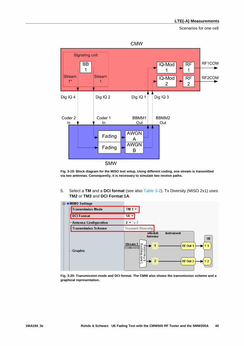
3.2.2.2 Tx Diversity (2x1 MISO) Configuration (TM2 or TM3)
To conduct the Tx diversity measurement, one signal is transmitted via two antennas
using different coding in order to achieve greater robustness. Here, too, there are two
different receive paths. Consequently, to take this measurement under fading
conditions, it is necessary to simulate two different receive paths. Tx Diversity is a fall
back mode in a couple of TM’s. The CMW uses TM2 or TM3.
LTE(-A) Measurements
Scenarios for one cell
1MA194_3e Rohde & Schwarz UE Fading Test with the CMW500 RF Tester and the SMW200A 40
Fig. 3-19: Block diagram for the MISO test setup. Using different coding, one stream is transmitted
via two antennas. Consequently, it is necessary to simulate two receive paths.
5. Select a TM and a DCI format (see also Table 3-2). Tx Diversity (MISO 2x1) uses
TM2 or TM3 and DCI Format 1A.
Fig. 3-20: Transmission mode and DCI format. The CMW also shows the transmission scheme and a
graphical representation.

LTE(-A) Measurements
Scenarios for one cell
1MA194_3e Rohde & Schwarz UE Fading Test with the CMW500 RF Tester and the SMW200A 41
Remote commands:
// set TM3
CONFigure:LTE:SIGN<i>:CONNection:TRANsmission TM3
// set DCI format 1A
CONFigure:LTE:SIGN<i>:CONNection:DCIFormat D1A
6. Use CONNECT to establish an LTE connection between the CMW and DUT.
7. If you modify the fading, remember to change the level accordingly in the CMW.
Fig. 3-21: SMW settings for fading two paths (SIMO and MISO).
8. Use Extended BLER to start the RX measurement (see section 3.1). Fig. 3-22
shows an example of an MISO measurement in the overview.
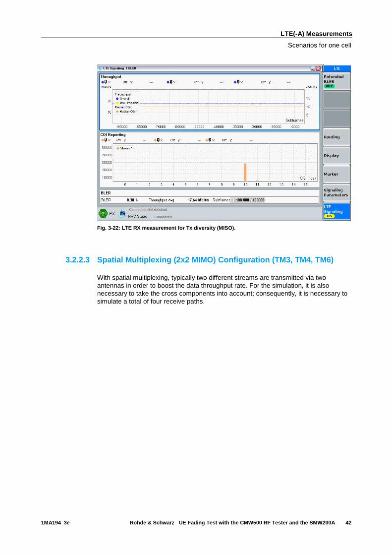
LTE(-A) Measurements
Scenarios for one cell
1MA194_3e Rohde & Schwarz UE Fading Test with the CMW500 RF Tester and the SMW200A 42
Fig. 3-22: LTE RX measurement for Tx diversity (MISO).
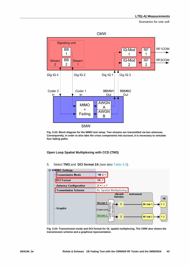
3.2.2.3 Spatial Multiplexing (2x2 MIMO) Configuration (TM3, TM4, TM6)
With spatial multiplexing, typically two different streams are transmitted via two
antennas in order to boost the data throughput rate. For the simulation, it is also
necessary to take the cross components into account; consequently, it is necessary to
simulate a total of four receive paths.
LTE(-A) Measurements
Scenarios for one cell
1MA194_3e Rohde & Schwarz UE Fading Test with the CMW500 RF Tester and the SMW200A 43
Fig. 3-23: Block diagram for the MIMO test setup. Two streams are transmitted via two antennas.
Consequently, in order to also take the cross components into account, it is necessary to simulate
four fading paths.
Open Loop Spatial Multiplexing with CCD (TM3)
5. Select TM3 and DCI format 2A (see also Table 3-2).
Fig. 3-24: Transmission mode and DCI format for OL spatial multiplexing. The CMW also shows the
transmission scheme and a graphical representation.

LTE(-A) Measurements
Scenarios for one cell
1MA194_3e Rohde & Schwarz UE Fading Test with the CMW500 RF Tester and the SMW200A 44
Remote commands:
// set TM3
CONFigure:LTE:SIGN<i>:CONNection:TRANsmission TM3
// set DCI format 1A
CONFigure:LTE:SIGN<i>:CONNection:DCIFormat D2A
Closed Loop Spatial Multiplexing (TM4)
5. Select TM4, DCI format 2 and a Precoding Matrix (see also Table 3-2).
Fig. 3-25: Transmission mode and DCI format for CL spatial multiplexing. The CMW also shows the
transmission scheme and a graphical representation.
Remote commands:
// set TM4
CONFigure:LTE:SIGN<i>:CONNection:TRANsmission TM4
// set DCI format 2
CONFigure:LTE:SIGN<i>:CONNection:DCIFormat D2
// set the Precoding Matrix to PMI0
CONFigure:LTE:SIGN<i>:CONNection:PMATrix PMI0
LTE(-A) Measurements
Scenarios for one cell
1MA194_3e Rohde & Schwarz UE Fading Test with the CMW500 RF Tester and the SMW200A 45
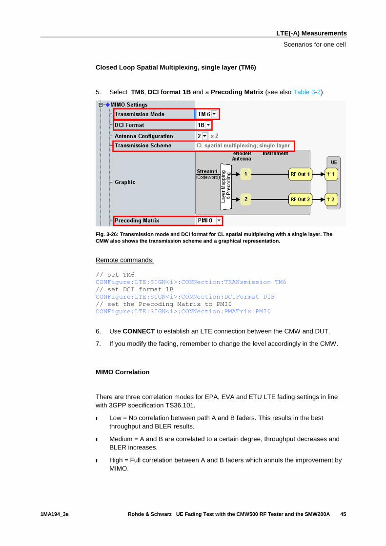
Closed Loop Spatial Multiplexing, single layer (TM6)
5. Select TM6, DCI format 1B and a Precoding Matrix (see also Table 3-2).
Fig. 3-26: Transmission mode and DCI format for CL spatial multiplexing with a single layer. The
CMW also shows the transmission scheme and a graphical representation.
Remote commands:
// set TM6
CONFigure:LTE:SIGN<i>:CONNection:TRANsmission TM6
// set DCI format 1B
CONFigure:LTE:SIGN<i>:CONNection:DCIFormat D1B
// set the Precoding Matrix to PMI0
CONFigure:LTE:SIGN<i>:CONNection:PMATrix PMI0
6. Use CONNECT to establish an LTE connection between the CMW and DUT.
7. If you modify the fading, remember to change the level accordingly in the CMW.
MIMO Correlation
There are three correlation modes for EPA, EVA and ETU LTE fading settings in line
with 3GPP specification TS36.101.
ı Low = No correlation between path A and B faders. This results in the best
throughput and BLER results.
ı Medium = A and B are correlated to a certain degree, throughput decreases and
BLER increases.
ı High = Full correlation between A and B faders which annuls the improvement by
MIMO.

LTE(-A) Measurements
Scenarios for one cell
1MA194_3e Rohde & Schwarz UE Fading Test with the CMW500 RF Tester and the SMW200A 46
Fig. 3-27: SMW settings for fading four paths (2x2 MIMO).
8. Use Extended BLER to start the RX measurement (see section 3.1). Fig. 3-28
shows an example of an MIMO measurement in the overview.
Fig. 3-28: LTE RX measurement for 2x2 MIMO. The measurements are adapted automatically for both
streams individually as well as in the form of an overall assessment.
LTE(-A) Measurements
Scenarios for one cell
1MA194_3e Rohde & Schwarz UE Fading Test with the CMW500 RF Tester and the SMW200A 47
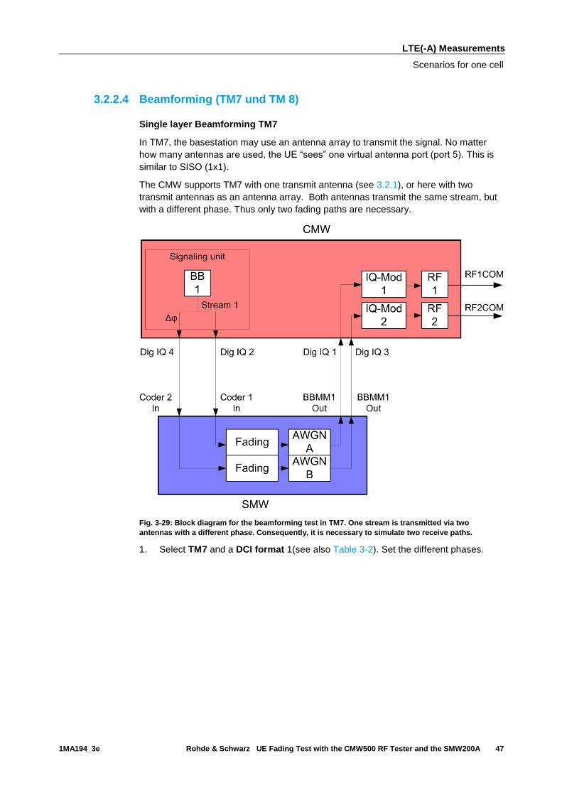
3.2.2.4 Beamforming (TM7 und TM 8)
Single layer Beamforming TM7
In TM7, the basestation may use an antenna array to transmit the signal. No matter
how many antennas are used, the UE “sees” one virtual antenna port (port 5). This is
similar to SISO (1x1).
The CMW supports TM7 with one transmit antenna (see 3.2.1), or here with two
transmit antennas as an antenna array. Both antennas transmit the same stream, but
with a different phase. Thus only two fading paths are necessary.
Fig. 3-29: Block diagram for the beamforming test in TM7. One stream is transmitted via two
antennas with a different phase. Consequently, it is necessary to simulate two receive paths.
1. Select TM7 and a DCI format 1(see also Table 3-2). Set the different phases.

LTE(-A) Measurements
Scenarios for one cell
1MA194_3e Rohde & Schwarz UE Fading Test with the CMW500 RF Tester and the SMW200A 48
Fig. 3-30: Transmission mode and DCI format. The CMW also shows the transmission scheme and a
graphical representation.
Remote commands:
// set TM7
CONFigure:LTE:SIGN<i>:CONNection:TRANsmission TM7
// set DCI format 1
CONFigure:LTE:SIGN<i>:CONNection:DCIFormat D1
// set beamforming mode ON
CONFigure:LTE:SIGN<i>:CONNection:BEAMforming:MODE ON
// set beamforming matrix 0°, 30°
CONFigure:LTE:SIGN<i>:CONNection:BEAMforming:MATRix 0,30
2. Use CONNECT to establish an LTE connection between the CMW and DUT.
3. If you modify the fading, remember to change the level accordingly in the CMW.
Fig. 3-31: SMW settings for fading two paths.
LTE(-A) Measurements
Scenarios for one cell
1MA194_3e Rohde & Schwarz UE Fading Test with the CMW500 RF Tester and the SMW200A 49
4. Use Extended BLER to start the RX measurement (see section 3.1).
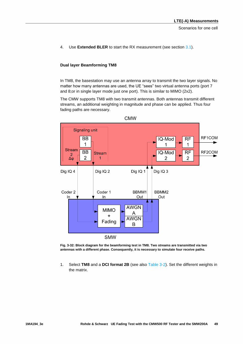
Dual layer Beamforming TM8
In TM8, the basestation may use an antenna array to transmit the two layer signals. No
matter how many antennas are used, the UE “sees” two virtual antenna ports (port 7
and 8;or in single layer mode just one port). This is similar to MIMO (2x2).
The CMW supports TM8 with two transmit antennas. Both antennas transmit different
streams, an additional weighting in magnitude and phase can be applied. Thus four
fading paths are necessary.
Fig. 3-32: Block diagram for the beamforming test in TM8. Two streams are transmitted via two
antennas with a different phase. Consequently, it is necessary to simulate four receive paths.
1. Select TM8 and a DCI format 2B (see also Table 3-2). Set the different weights in
the matrix.
LTE(-A) Measurements
Scenarios for one cell
1MA194_3e Rohde & Schwarz UE Fading Test with the CMW500 RF Tester and the SMW200A 50
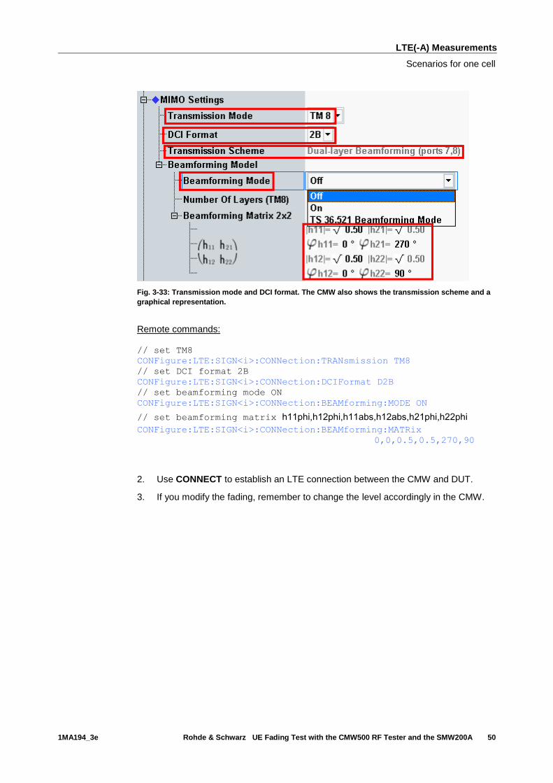
Fig. 3-33: Transmission mode and DCI format. The CMW also shows the transmission scheme and a
graphical representation.
Remote commands:
// set TM8
CONFigure:LTE:SIGN<i>:CONNection:TRANsmission TM8
// set DCI format 2B
CONFigure:LTE:SIGN<i>:CONNection:DCIFormat D2B
// set beamforming mode ON
CONFigure:LTE:SIGN<i>:CONNection:BEAMforming:MODE ON
// set beamforming matrix h11phi,h12phi,h11abs,h12abs,h21phi,h22phi
CONFigure:LTE:SIGN<i>:CONNection:BEAMforming:MATRix
0,0,0.5,0.5,270,90
2. Use CONNECT to establish an LTE connection between the CMW and DUT.
3. If you modify the fading, remember to change the level accordingly in the CMW.
LTE(-A) Measurements
Scenarios for one cell
1MA194_3e Rohde & Schwarz UE Fading Test with the CMW500 RF Tester and the SMW200A 51
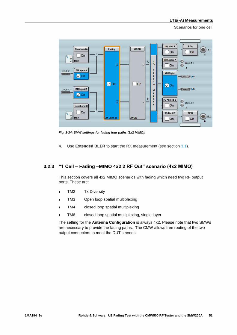
Fig. 3-34: SMW settings for fading four paths (2x2 MIMO).
4. Use Extended BLER to start the RX measurement (see section 3.1).
3.2.3 “1 Cell – Fading –MIMO 4x2 2 RF Out” scenario (4x2 MIMO)
This section covers all 4x2 MIMO scenarios with fading which need two RF output
ports. These are:
ı TM2 Tx Diversity
ı TM3 Open loop spatial multiplexing
ı TM4 closed loop spatial multiplexing
ı TM6 closed loop spatial multiplexing, single layer
The setting for the Antenna Configuration is always 4x2. Please note that two SMWs
are necessary to provide the fading paths. The CMW allows free routing of the two
output connectors to meet the DUT’s needs.
LTE(-A) Measurements
Scenarios for one cell
1MA194_3e Rohde & Schwarz UE Fading Test with the CMW500 RF Tester and the SMW200A 52
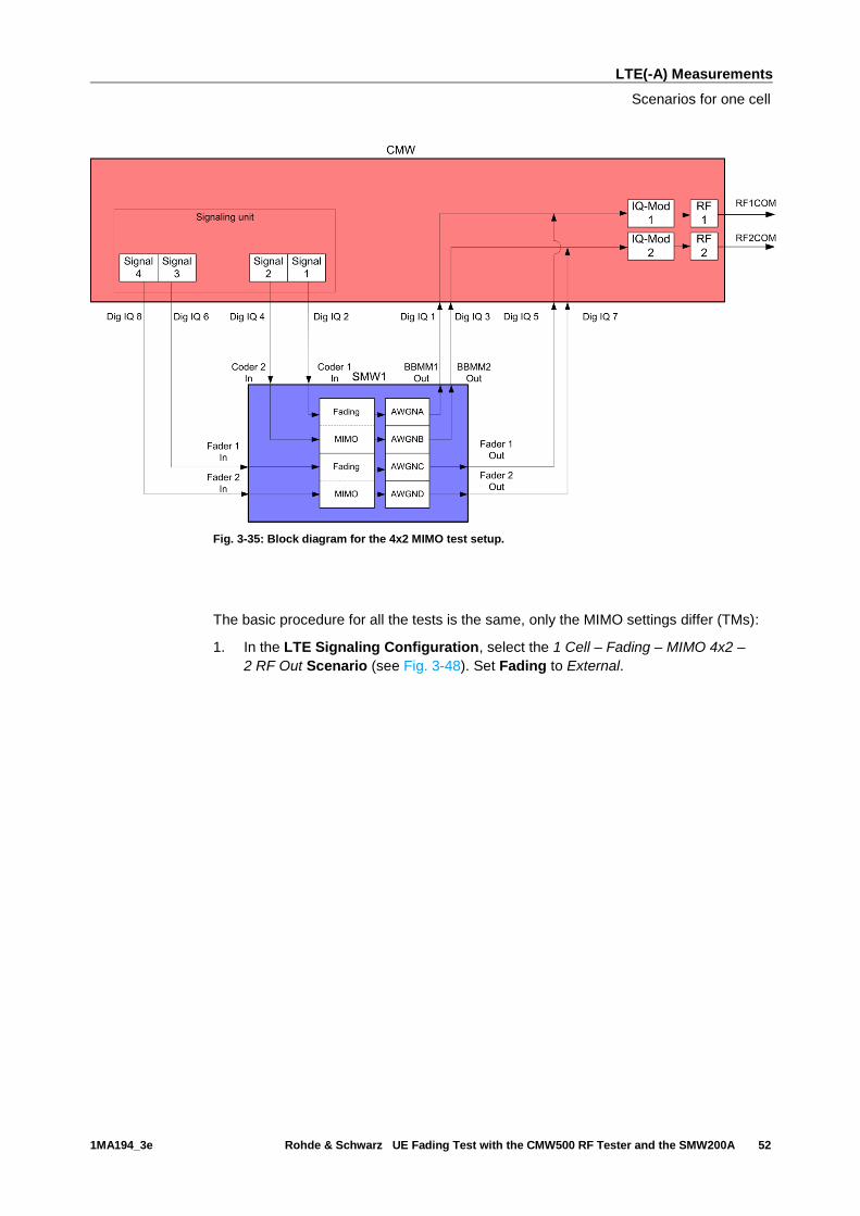
Fig. 3-35: Block diagram for the 4x2 MIMO test setup.
The basic procedure for all the tests is the same, only the MIMO settings differ (TMs):
1. In the LTE Signaling Configuration, select the 1 Cell – Fading – MIMO 4x2 –
2 RF Out Scenario (see Fig. 3-48). Set Fading to External.
LTE(-A) Measurements
Scenarios for one cell
1MA194_3e Rohde & Schwarz UE Fading Test with the CMW500 RF Tester and the SMW200A 53
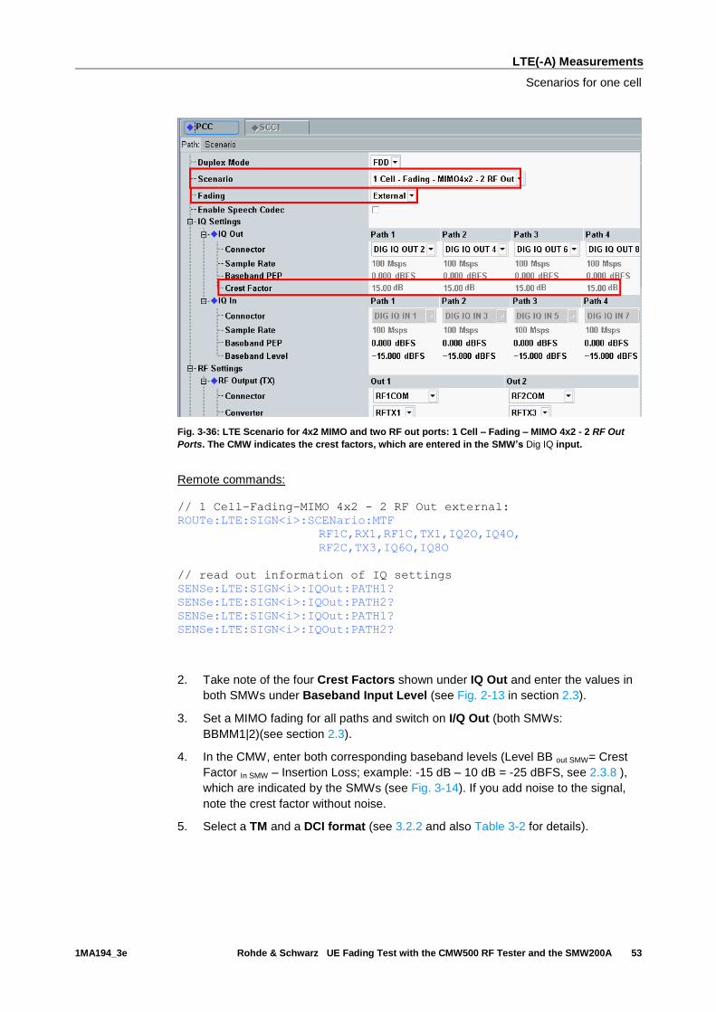
Fig. 3-36: LTE Scenario for 4x2 MIMO and two RF out ports: 1 Cell – Fading – MIMO 4x2 - 2 RF Out
Ports. The CMW indicates the crest factors, which are entered in the SMW’s Dig IQ input.
Remote commands:
// 1 Cell–Fading–MIMO 4x2 - 2 RF Out external:
ROUTe:LTE:SIGN<i>:SCENario:MTF
RF1C,RX1,RF1C,TX1,IQ2O,IQ4O,
RF2C,TX3,IQ6O,IQ8O
// read out information of IQ settings
SENSe:LTE:SIGN<i>:IQOut:PATH1?
SENSe:LTE:SIGN<i>:IQOut:PATH2?
SENSe:LTE:SIGN<i>:IQOut:PATH1?
SENSe:LTE:SIGN<i>:IQOut:PATH2?
2. Take note of the four Crest Factors shown under IQ Out and enter the values in
both SMWs under Baseband Input Level (see Fig. 2-13 in section 2.3).
3. Set a MIMO fading for all paths and switch on I/Q Out (both SMWs:
BBMM1|2)(see section 2.3).
4. In the CMW, enter both corresponding baseband levels (Level BB out SMW= Crest
Factor In SMW – Insertion Loss; example: -15 dB – 10 dB = -25 dBFS, see 2.3.8 ),
which are indicated by the SMWs (see Fig. 3-14). If you add noise to the signal,
note the crest factor without noise.
5. Select a TM and a DCI format (see 3.2.2 and also Table 3-2 for details).

LTE(-A) Measurements
Scenarios for one cell
1MA194_3e Rohde & Schwarz UE Fading Test with the CMW500 RF Tester and the SMW200A 54
Fig. 3-37: Example for the 4x2 MIMO fading with TM4. The antenna configuration is fixed to 4x2.
6. Use CONNECT to establish an LTE connection between the CMW and DUT.
7. If you modify the fading, remember to change the level accordingly in the CMW.
Fig. 3-38: The SMW shows the necessary insertion loss (example: 16 dB)

LTE(-A) Measurements
Scenarios for Carrier Aggregation
1MA194_3e Rohde & Schwarz UE Fading Test with the CMW500 RF Tester and the SMW200A 55
Fig. 3-39: Compensating for the necessary attenuation in the CMW. Here, the levels of the SMWs
signals are entered as the IQ IN levels.
Remote commands:
// set IQ In to PEP 0 dBFS and Level -31 dBFS
CONFigure:LTE:SIGN<i>:IQIN:PATH1 0.0, -31.0
CONFigure:LTE:SIGN<i>:IQIN:PATH2 0.0, -31.0
CONFigure:LTE:SIGN<i>:IQIN:PATH1 0.0, -31.0
CONFigure:LTE:SIGN<i>:IQIN:PATH2 0.0, -31.0
8. Start the RX measurement using Extended BLER (see section 3.1)
3.3 Scenarios for Carrier Aggregation
This section covers tests with carrier aggregation (CA) for two downlink component
carriers (CC: Primary CC (PCC) and Secondary CC (SCC1). Different transmission
modes require different fading paths. In the CMW these scenarios differ by the number
of the used RF outputs. The CMW supports all possible frequency allocations in CA
(intra-band contiguous, intra-band non- contiguous and inter-band). Both CCs can be
set up independently of each other.
3.3.1 “2CC CA – Fading – 2 RF Out” scenario (CA with SISO)
This configuration uses only one data stream per CC via one antenna. Thus two RF
connectors are needed. It covers tests for:
LTE(-A) Measurements
Scenarios for Carrier Aggregation
1MA194_3e Rohde & Schwarz UE Fading Test with the CMW500 RF Tester and the SMW200A 56
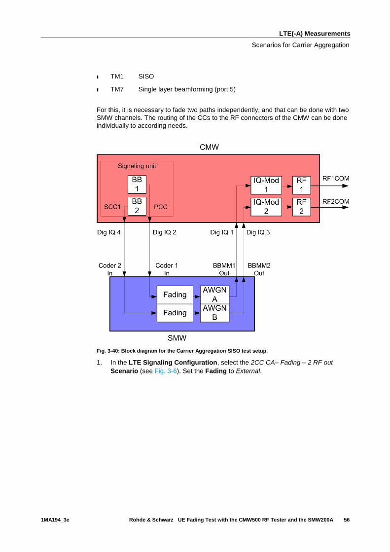
ı TM1 SISO
ı TM7 Single layer beamforming (port 5)
For this, it is necessary to fade two paths independently, and that can be done with two
SMW channels. The routing of the CCs to the RF connectors of the CMW can be done
individually to according needs.
Fig. 3-40: Block diagram for the Carrier Aggregation SISO test setup.
1. In the LTE Signaling Configuration, select the 2CC CA– Fading – 2 RF out
Scenario (see Fig. 3-6). Set the Fading to External.

LTE(-A) Measurements
Scenarios for Carrier Aggregation
1MA194_3e Rohde & Schwarz UE Fading Test with the CMW500 RF Tester and the SMW200A 57
Fig. 3-41: LTE scenario for Carrier Aggregation SISO: 2CC CA Fading. The CMW indicates the crest
factors for both component carriers, which are entered in the SMW’s Dig IQ Inputs.
Remote commands:
// 2CC CA–Fading– 2 RF Out external via RF1COM, IQ2 Out and
// RF3COM, IQ4 Out
ROUTe:LTE:SIGN:SCENario:CATF
RF1C,RX1,RF1C,TX1,IQ2O,RF3C,TX2,IQ4O
// read out information of IQ settings
SENSe:LTE:SIGN<i>:IQOut[:PCC]:PATH<n>?
SENSe:LTE:SIGN<i>:IQOut:SCC:PATH<n>?
2. Take note of the Crest Factors under IQ Out and enter the values in the SMW
under Baseband Input Level (see Fig. 2-13 in section 2.3).
3. Set a fading and switch on both I/Q Out (BBMM1/2)(see section 2.3).
4. In the CMW, enter the corresponding baseband levels (Level BB out SMW= Crest
Factor In SMW – Insertion Loss; example: -15 dB – 10 dB = -25 dBFS, see 2.3.8 ),
which are indicated by the SMW (see Fig. 3-44). If you add noise to the signal,
note the crest factors without noise.
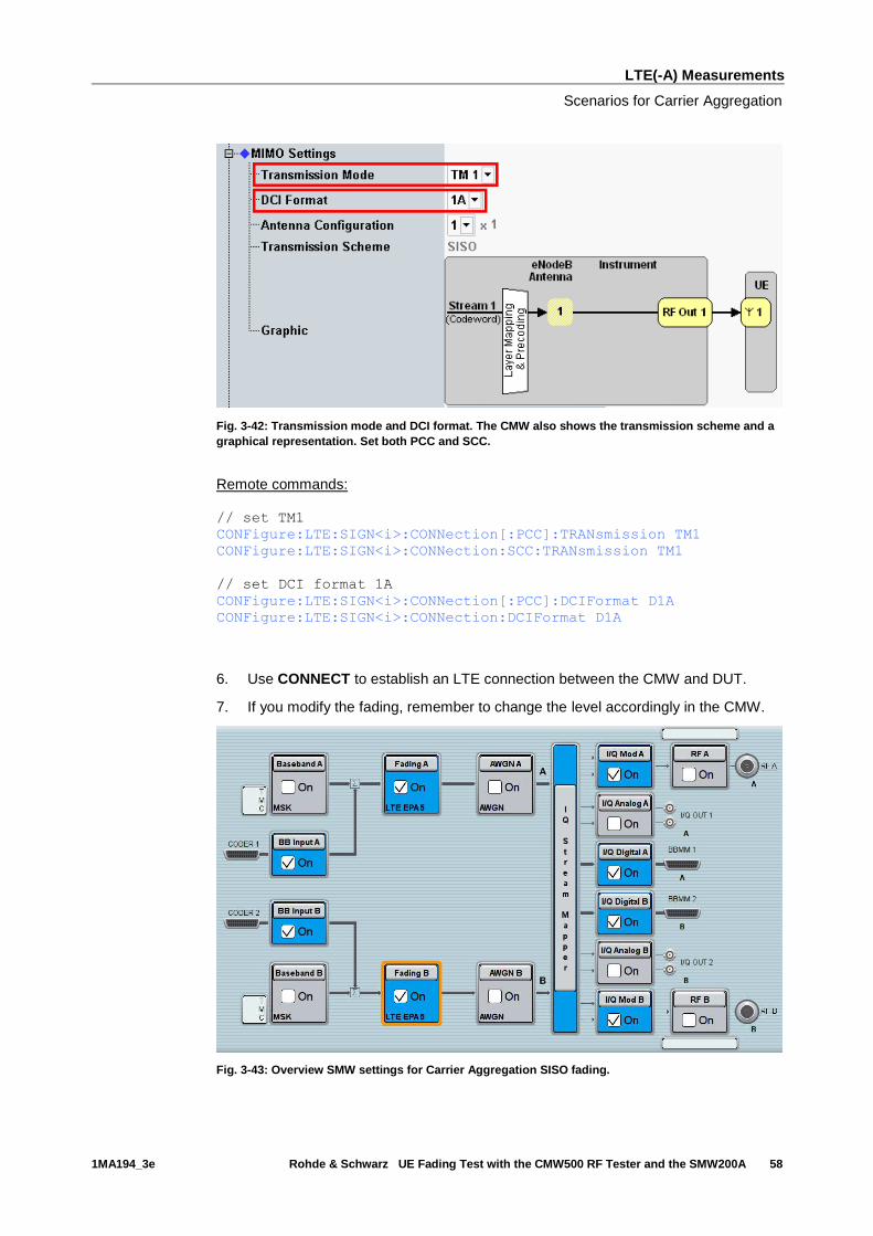
5. Select a TM and a DCI format both for PCC and SCC (see also Table 3-2)
LTE(-A) Measurements
Scenarios for Carrier Aggregation
1MA194_3e Rohde & Schwarz UE Fading Test with the CMW500 RF Tester and the SMW200A 58
Fig. 3-42: Transmission mode and DCI format. The CMW also shows the transmission scheme and a
graphical representation. Set both PCC and SCC.
Remote commands:
// set TM1
CONFigure:LTE:SIGN<i>:CONNection[:PCC]:TRANsmission TM1
CONFigure:LTE:SIGN<i>:CONNection:SCC:TRANsmission TM1
// set DCI format 1A
CONFigure:LTE:SIGN<i>:CONNection[:PCC]:DCIFormat D1A
CONFigure:LTE:SIGN<i>:CONNection:DCIFormat D1A
6. Use CONNECT to establish an LTE connection between the CMW and DUT.
7. If you modify the fading, remember to change the level accordingly in the CMW.
Fig. 3-43: Overview SMW settings for Carrier Aggregation SISO fading.

LTE(-A) Measurements
Scenarios for Carrier Aggregation
1MA194_3e Rohde & Schwarz UE Fading Test with the CMW500 RF Tester and the SMW200A 59
Fig. 3-44: The SMW shows the necessary insertion loss (example: 10 dB)
Fig. 3-45: Making allowance for the necessary attenuation in the CMW. Here, the digital output level
of the SMW signal is entered as the IQ In level.
Remote command:
// set IQ In to PEP 0 dBFS and Level -25 dBFS
CONFigure:LTE:SIGN<i>:IQIN[:PCC]:PATH<n> 0.0, -25.0
CONFigure:LTE:SIGN<i>:IQIN:SCC:PATH<n> 0.0, -25.0
8. Start the RX measurement using Extended BLER (see section 3.1). Fig. 3-46
shows an example of a Carrier Aggregation SISO measurement in the overview.
LTE(-A) Measurements
Scenarios for Carrier Aggregation
1MA194_3e Rohde & Schwarz UE Fading Test with the CMW500 RF Tester and the SMW200A 60
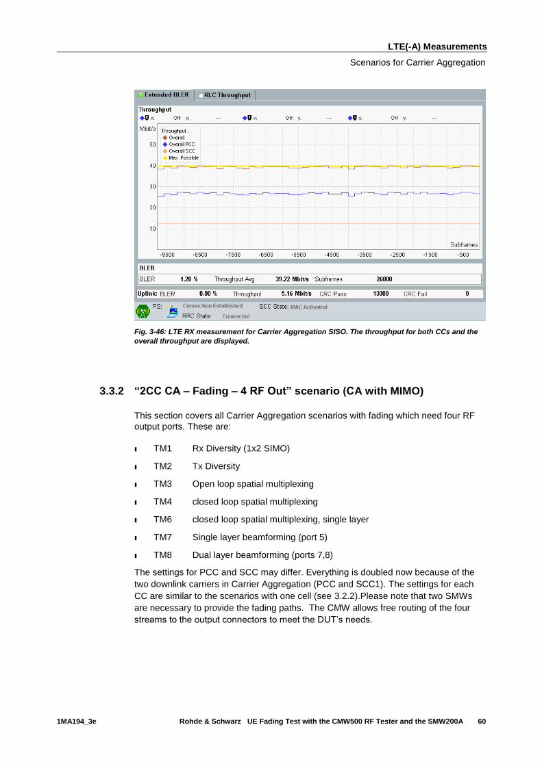
Fig. 3-46: LTE RX measurement for Carrier Aggregation SISO. The throughput for both CCs and the
overall throughput are displayed.
3.3.2 “2CC CA – Fading – 4 RF Out” scenario (CA with MIMO)
This section covers all Carrier Aggregation scenarios with fading which need four RF
output ports. These are:
ı TM1 Rx Diversity (1x2 SIMO)
ı TM2 Tx Diversity
ı TM3 Open loop spatial multiplexing
ı TM4 closed loop spatial multiplexing
ı TM6 closed loop spatial multiplexing, single layer
ı TM7 Single layer beamforming (port 5)
ı TM8 Dual layer beamforming (ports 7,8)
The settings for PCC and SCC may differ. Everything is doubled now because of the
two downlink carriers in Carrier Aggregation (PCC and SCC1). The settings for each
CC are similar to the scenarios with one cell (see 3.2.2).Please note that two SMWs
are necessary to provide the fading paths. The CMW allows free routing of the four
streams to the output connectors to meet the DUT’s needs.

LTE(-A) Measurements
Scenarios for Carrier Aggregation
1MA194_3e Rohde & Schwarz UE Fading Test with the CMW500 RF Tester and the SMW200A 61
Fig. 3-47: Block diagram for the Carrier Aggregation MIMO test setup. The streams and the
MIMO/Fading setup depend on the used transmission mode (TM)
The basic procedure for all the tests is the same, only the MIMO settings differ (TMs):
1. In the LTE Signaling Configuration, select the 2CC CA – Fading – 4 RF Out
Scenario (see Fig. 3-48). Set Fading to External.
Fig. 3-48: LTE Scenario for Carrier Aggregation with MIMO and four RF out ports: 2CC CA – Fading –
4 RF Out Ports. The CMW indicates the crest factors, which are entered in the SMW’s Dig IQ input.
LTE(-A) Measurements
Scenarios for Carrier Aggregation
1MA194_3e Rohde & Schwarz UE Fading Test with the CMW500 RF Tester and the SMW200A 62
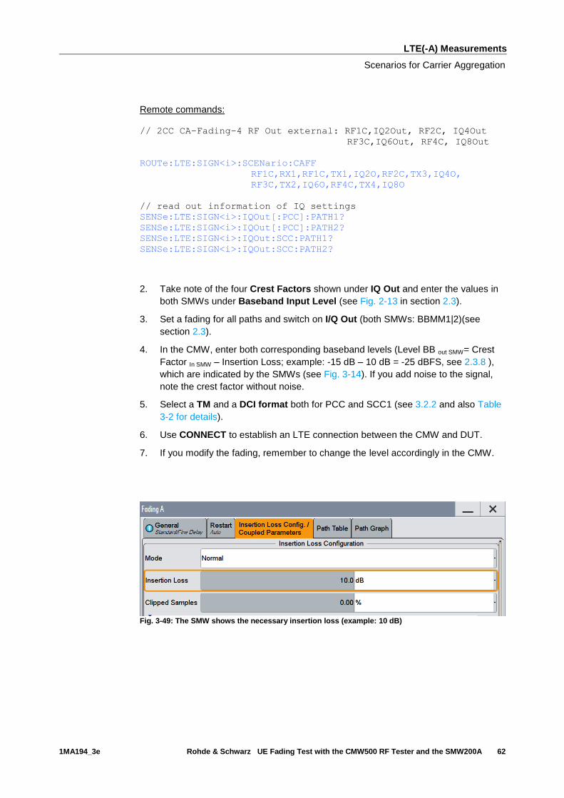
Remote commands:
// 2CC CA–Fading–4 RF Out external: RF1C,IQ2Out, RF2C, IQ4Out
RF3C,IQ6Out, RF4C, IQ8Out
ROUTe:LTE:SIGN<i>:SCENario:CAFF
RF1C,RX1,RF1C,TX1,IQ2O,RF2C,TX3,IQ4O,
RF3C,TX2,IQ6O,RF4C,TX4,IQ8O
// read out information of IQ settings
SENSe:LTE:SIGN<i>:IQOut[:PCC]:PATH1?
SENSe:LTE:SIGN<i>:IQOut[:PCC]:PATH2?
SENSe:LTE:SIGN<i>:IQOut:SCC:PATH1?
SENSe:LTE:SIGN<i>:IQOut:SCC:PATH2?
2. Take note of the four Crest Factors shown under IQ Out and enter the values in
both SMWs under Baseband Input Level (see Fig. 2-13 in section 2.3).
3. Set a fading for all paths and switch on I/Q Out (both SMWs: BBMM1|2)(see
section 2.3).
4. In the CMW, enter both corresponding baseband levels (Level BB out SMW= Crest
Factor In SMW – Insertion Loss; example: -15 dB – 10 dB = -25 dBFS, see 2.3.8 ),
which are indicated by the SMWs (see Fig. 3-14). If you add noise to the signal,
note the crest factor without noise.
5. Select a TM and a DCI format both for PCC and SCC1 (see 3.2.2 and also Table
3-2 for details).
6. Use CONNECT to establish an LTE connection between the CMW and DUT.
7. If you modify the fading, remember to change the level accordingly in the CMW.
Fig. 3-49: The SMW shows the necessary insertion loss (example: 10 dB)

LTE(-A) Measurements
Scenarios for Carrier Aggregation
1MA194_3e Rohde & Schwarz UE Fading Test with the CMW500 RF Tester and the SMW200A 63
Fig. 3-50: Compensating for the necessary attenuation in the CMW. Here, the levels of the SMWs
signals are entered as the IQ IN levels.
Remote commands:
// set IQ In to PEP 0 dBFS and Level -25 dBFS
CONFigure:LTE:SIGN<i>:IQIN[:PCC]:PATH1 0.0, -25.0
CONFigure:LTE:SIGN<i>:IQIN[:PCC]:PATH2 0.0, -25.0
CONFigure:LTE:SIGN<i>:IQIN:SCC:PATH1 0.0, -25.0
CONFigure:LTE:SIGN<i>:IQIN:SCC:PATH2 0.0, -25.0
8. Start the RX measurement using Extended BLER (see section 3.1)
Fig. 3-51: Example for a Throughput measurement with four RF output paths: a CA test with TM4 (2x2
MIMO) for each CC is used.

LTE(-A) Measurements
Scenarios for Carrier Aggregation with CMWflexx
1MA194_3e Rohde & Schwarz UE Fading Test with the CMW500 RF Tester and the SMW200A 64
3.4 Scenarios for Carrier Aggregation with CMWflexx
This section covers tests with carrier aggregation (CA) for more than two downlink
component carriers (CC: Primary CC (PCC) and Secondary CC (SCCx). Different
transmission modes require different fading paths. In the CMW these scenarios differ
by the number of the used RF outputs. The CMW supports all possible frequency
allocations in CA (intra-band contiguous, intra-band non- contiguous and inter-band).
All CCs can be set up independently of each other.
The CMWflexx provides more than 2 CC’s with MIMO each, therefore more than one
CMW is used. The CMW Controller (CMWC) allows easy manual and remote control, it
acts like one CMW with extended RF hardware.
3.4.1 “2CC CA – Fading – 4 RF Out Distributed” scenario (CA with
MIMO)
This scenario is the same like in 3.3.2, with the difference that both CMW’s are used so
the RF ports are distributed over the two CMW’s.
The procedure is the same like in 3.3.2, only the scenario setting and the used RF
ports differ:
1. In the LTE Signaling Configuration, select the 2CC CA – Fading – 4 RF Out-
Distributed Scenario (see Fig. 3-48). Set Fading to External.
Fig. 3-52: LTE Scenario for Carrier Aggregation with MIMO and four distributed RF out ports: 2CC CA
– Fading – 4 RF Out Distributed Ports. The CMW sets the used RF out ports automatically
LTE(-A) Measurements
Scenarios for Carrier Aggregation with CMWflexx
1MA194_3e Rohde & Schwarz UE Fading Test with the CMW500 RF Tester and the SMW200A 65
Remote commands:
// 2CC CA–Fading–4 RF Out distributed external: routing is done
// automatically. Use query to ask settings
ROUTe:LTE:SIGN<i>:SCENario:BDFD:FIX
3.4.2 “3CC CA – Fading – 6 RF Out” scenario (CA with 3 CC’s and
MIMO)
This section covers all Carrier Aggregation scenarios with fading which need six RF
output ports. These are:
ı TM1 Rx Diversity (1x2 SIMO)
ı TM2 Tx Diversity
ı TM3 Open loop spatial multiplexing
ı TM4 closed loop spatial multiplexing
ı TM6 closed loop spatial multiplexing, single layer
ı TM7 Single layer beamforming (port 5)
ı TM8 Dual layer beamforming (ports 7,8)
ı TM9 Dual layer beamforming (ports 7,8)
The settings for PCC, SCC1 and SCC2 may differ. Everything is tripled now because
of the three downlink carriers in Carrier Aggregation (PCC, SCC1 and SCC2). The
settings for each CC are similar to the scenarios with one cell (see 3.2.2).Please note
that two SMWs are necessary to provide the fading paths.

LTE(-A) Measurements
Scenarios for Carrier Aggregation with CMWflexx
1MA194_3e Rohde & Schwarz UE Fading Test with the CMW500 RF Tester and the SMW200A 66
Fig. 3-53: Block diagram for the three Carrier Aggregation MIMO test setup. The streams and the
MIMO/Fading setup depend on the used transmission mode (TM)
The basic procedure for all the tests is the same, only the MIMO settings differ (TMs):
2. In the LTE Signaling Configuration, select the 3CC CA – Fading – 6 RF Out
Scenario (see Fig. 3-48). Set Fading to External.
LTE(-A) Measurements
Scenarios for Carrier Aggregation with CMWflexx
1MA194_3e Rohde & Schwarz UE Fading Test with the CMW500 RF Tester and the SMW200A 67
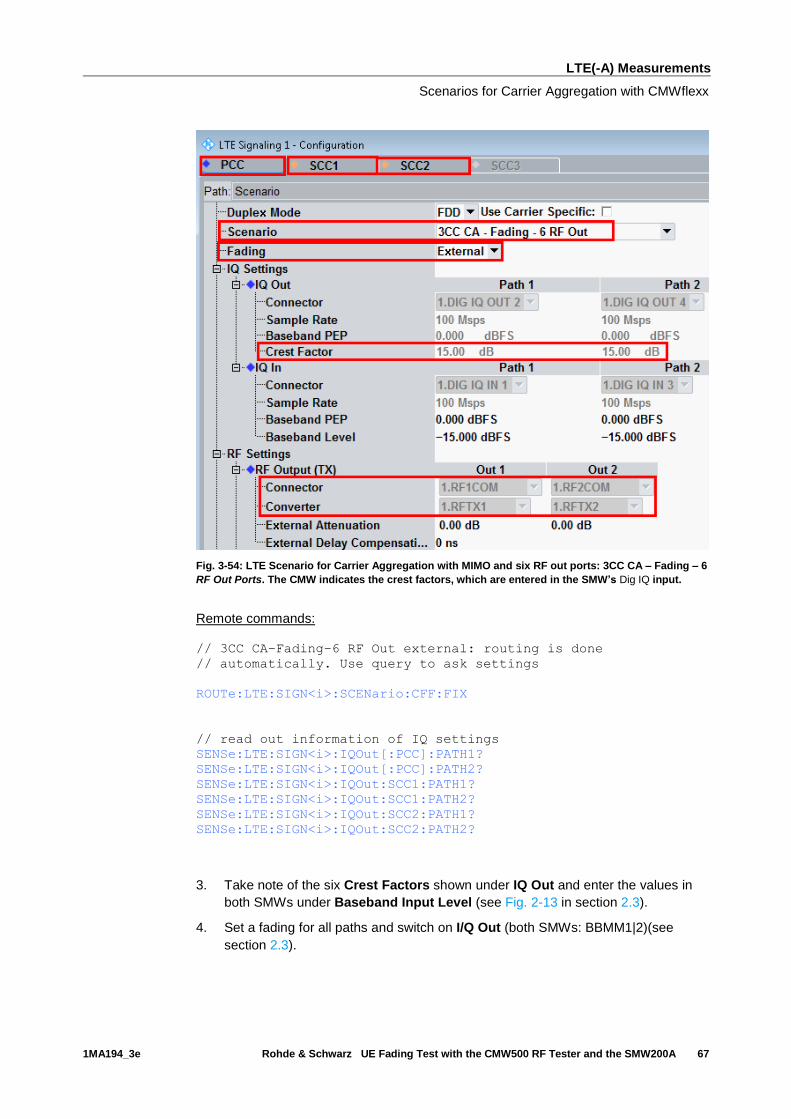
Fig. 3-54: LTE Scenario for Carrier Aggregation with MIMO and six RF out ports: 3CC CA – Fading – 6
RF Out Ports. The CMW indicates the crest factors, which are entered in the SMW’s Dig IQ input.
Remote commands:
// 3CC CA–Fading–6 RF Out external: routing is done
// automatically. Use query to ask settings
ROUTe:LTE:SIGN<i>:SCENario:CFF:FIX
// read out information of IQ settings
SENSe:LTE:SIGN<i>:IQOut[:PCC]:PATH1?
SENSe:LTE:SIGN<i>:IQOut[:PCC]:PATH2?
SENSe:LTE:SIGN<i>:IQOut:SCC1:PATH1?
SENSe:LTE:SIGN<i>:IQOut:SCC1:PATH2?
SENSe:LTE:SIGN<i>:IQOut:SCC2:PATH1?
SENSe:LTE:SIGN<i>:IQOut:SCC2:PATH2?
3. Take note of the six Crest Factors shown under IQ Out and enter the values in
both SMWs under Baseband Input Level (see Fig. 2-13 in section 2.3).
4. Set a fading for all paths and switch on I/Q Out (both SMWs: BBMM1|2)(see
section 2.3).
LTE(-A) Measurements
Scenarios for Carrier Aggregation with CMWflexx
1MA194_3e Rohde & Schwarz UE Fading Test with the CMW500 RF Tester and the SMW200A 68
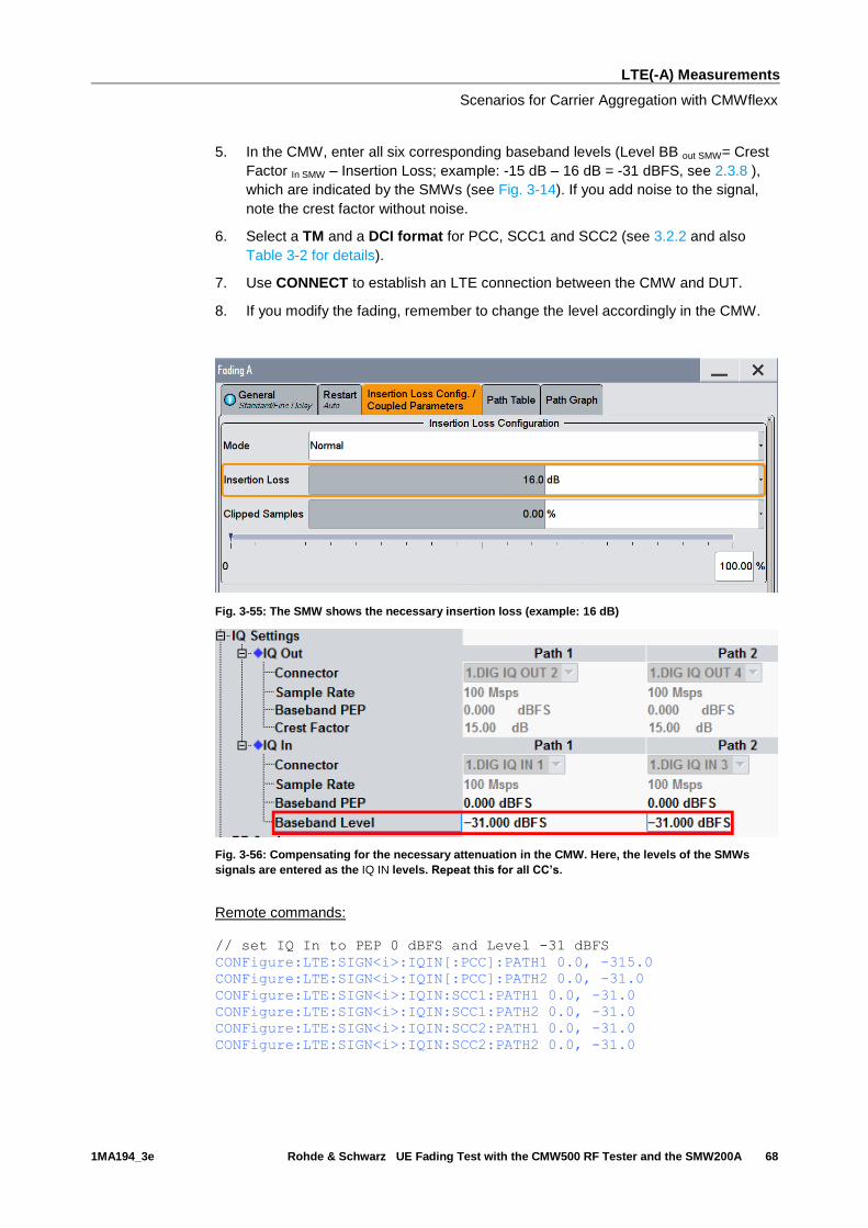
5. In the CMW, enter all six corresponding baseband levels (Level BB out SMW= Crest
Factor In SMW – Insertion Loss; example: -15 dB – 16 dB = -31 dBFS, see 2.3.8 ),
which are indicated by the SMWs (see Fig. 3-14). If you add noise to the signal,
note the crest factor without noise.
6. Select a TM and a DCI format for PCC, SCC1 and SCC2 (see 3.2.2 and also
Table 3-2 for details).
7. Use CONNECT to establish an LTE connection between the CMW and DUT.
8. If you modify the fading, remember to change the level accordingly in the CMW.
Fig. 3-55: The SMW shows the necessary insertion loss (example: 16 dB)
Fig. 3-56: Compensating for the necessary attenuation in the CMW. Here, the levels of the SMWs
signals are entered as the IQ IN levels. Repeat this for all CC’s.
Remote commands:
// set IQ In to PEP 0 dBFS and Level -31 dBFS
CONFigure:LTE:SIGN<i>:IQIN[:PCC]:PATH1 0.0, -315.0
CONFigure:LTE:SIGN<i>:IQIN[:PCC]:PATH2 0.0, -31.0
CONFigure:LTE:SIGN<i>:IQIN:SCC1:PATH1 0.0, -31.0
CONFigure:LTE:SIGN<i>:IQIN:SCC1:PATH2 0.0, -31.0
CONFigure:LTE:SIGN<i>:IQIN:SCC2:PATH1 0.0, -31.0
CONFigure:LTE:SIGN<i>:IQIN:SCC2:PATH2 0.0, -31.0
LTE(-A) Measurements
Scenarios for Carrier Aggregation with CMWflexx
1MA194_3e Rohde & Schwarz UE Fading Test with the CMW500 RF Tester and the SMW200A 69
9. Start the RX measurement using Extended BLER (see section 3.1)
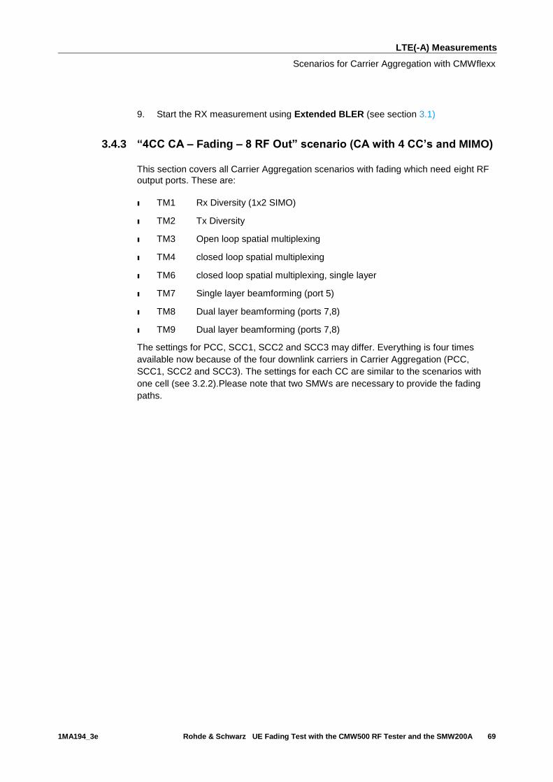
3.4.3 “4CC CA – Fading – 8 RF Out” scenario (CA with 4 CC’s and MIMO)
This section covers all Carrier Aggregation scenarios with fading which need eight RF
output ports. These are:
ı TM1 Rx Diversity (1x2 SIMO)
ı TM2 Tx Diversity
ı TM3 Open loop spatial multiplexing
ı TM4 closed loop spatial multiplexing
ı TM6 closed loop spatial multiplexing, single layer
ı TM7 Single layer beamforming (port 5)
ı TM8 Dual layer beamforming (ports 7,8)
ı TM9 Dual layer beamforming (ports 7,8)
The settings for PCC, SCC1, SCC2 and SCC3 may differ. Everything is four times
available now because of the four downlink carriers in Carrier Aggregation (PCC,
SCC1, SCC2 and SCC3). The settings for each CC are similar to the scenarios with
one cell (see 3.2.2).Please note that two SMWs are necessary to provide the fading
paths.
LTE(-A) Measurements
Scenarios for Carrier Aggregation with CMWflexx
1MA194_3e Rohde & Schwarz UE Fading Test with the CMW500 RF Tester and the SMW200A 70
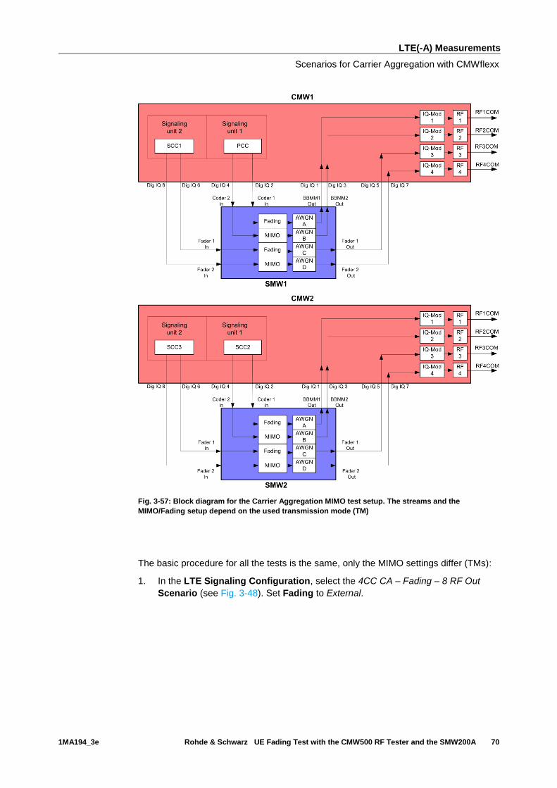
Fig. 3-57: Block diagram for the Carrier Aggregation MIMO test setup. The streams and the
MIMO/Fading setup depend on the used transmission mode (TM)
The basic procedure for all the tests is the same, only the MIMO settings differ (TMs):
1. In the LTE Signaling Configuration, select the 4CC CA – Fading – 8 RF Out
Scenario (see Fig. 3-48). Set Fading to External.
LTE(-A) Measurements
Scenarios for Carrier Aggregation with CMWflexx
1MA194_3e Rohde & Schwarz UE Fading Test with the CMW500 RF Tester and the SMW200A 71
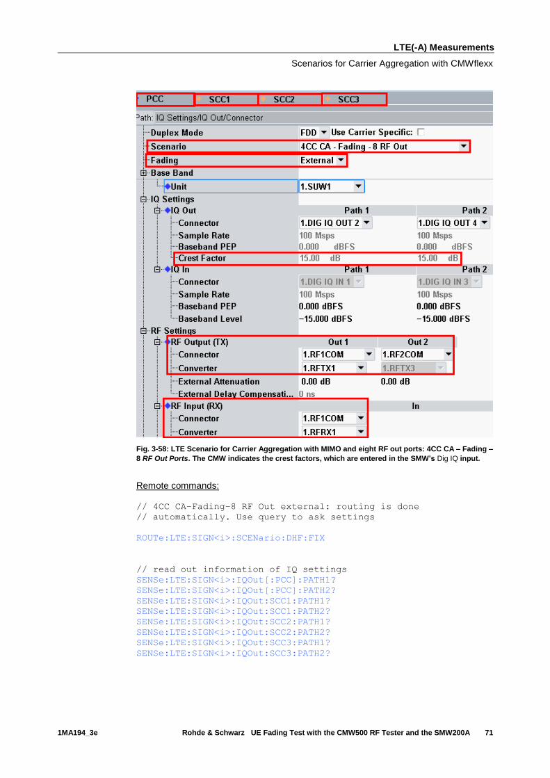
Fig. 3-58: LTE Scenario for Carrier Aggregation with MIMO and eight RF out ports: 4CC CA – Fading –
8 RF Out Ports. The CMW indicates the crest factors, which are entered in the SMW’s Dig IQ input.
Remote commands:
// 4CC CA–Fading–8 RF Out external: routing is done
// automatically. Use query to ask settings
ROUTe:LTE:SIGN<i>:SCENario:DHF:FIX
// read out information of IQ settings
SENSe:LTE:SIGN<i>:IQOut[:PCC]:PATH1?
SENSe:LTE:SIGN<i>:IQOut[:PCC]:PATH2?
SENSe:LTE:SIGN<i>:IQOut:SCC1:PATH1?
SENSe:LTE:SIGN<i>:IQOut:SCC1:PATH2?
SENSe:LTE:SIGN<i>:IQOut:SCC2:PATH1?
SENSe:LTE:SIGN<i>:IQOut:SCC2:PATH2?
SENSe:LTE:SIGN<i>:IQOut:SCC3:PATH1?
SENSe:LTE:SIGN<i>:IQOut:SCC3:PATH2?
LTE(-A) Measurements
Scenarios for Carrier Aggregation with CMWflexx
1MA194_3e Rohde & Schwarz UE Fading Test with the CMW500 RF Tester and the SMW200A 72
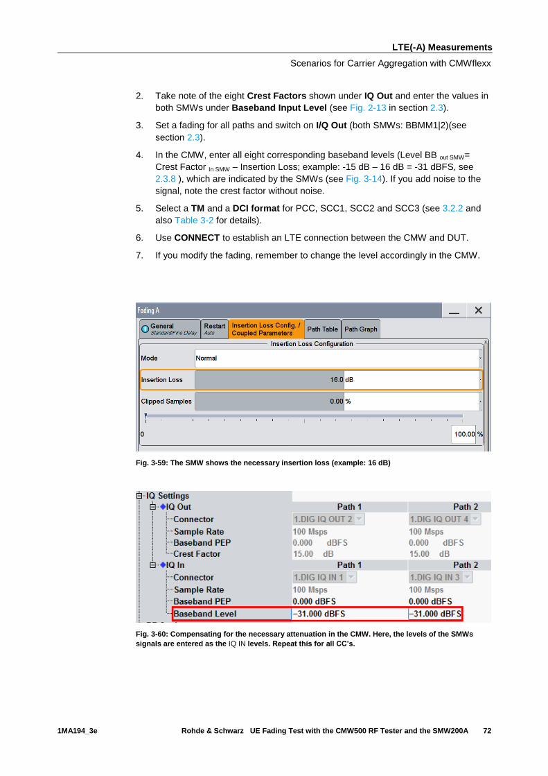
2. Take note of the eight Crest Factors shown under IQ Out and enter the values in
both SMWs under Baseband Input Level (see Fig. 2-13 in section 2.3).
3. Set a fading for all paths and switch on I/Q Out (both SMWs: BBMM1|2)(see
section 2.3).
4. In the CMW, enter all eight corresponding baseband levels (Level BB out SMW=
Crest Factor In SMW – Insertion Loss; example: -15 dB – 16 dB = -31 dBFS, see
2.3.8 ), which are indicated by the SMWs (see Fig. 3-14). If you add noise to the
signal, note the crest factor without noise.
5. Select a TM and a DCI format for PCC, SCC1, SCC2 and SCC3 (see 3.2.2 and
also Table 3-2 for details).
6. Use CONNECT to establish an LTE connection between the CMW and DUT.
7. If you modify the fading, remember to change the level accordingly in the CMW.
Fig. 3-59: The SMW shows the necessary insertion loss (example: 16 dB)
Fig. 3-60: Compensating for the necessary attenuation in the CMW. Here, the levels of the SMWs
signals are entered as the IQ IN levels. Repeat this for all CC’s.

LTE(-A) Measurements
CMW Internal Fading for LTE(-A)
1MA194_3e Rohde & Schwarz UE Fading Test with the CMW500 RF Tester and the SMW200A 73
Remote commands:
// set IQ In to PEP 0 dBFS and Level -31 dBFS
CONFigure:LTE:SIGN<i>:IQIN[:PCC]:PATH1 0.0, -31.0
CONFigure:LTE:SIGN<i>:IQIN[:PCC]:PATH2 0.0, -31.0
CONFigure:LTE:SIGN<i>:IQIN:SCC1:PATH1 0.0, -31.0
CONFigure:LTE:SIGN<i>:IQIN:SCC1:PATH2 0.0, -31.0
CONFigure:LTE:SIGN<i>:IQIN:SCC2:PATH1 0.0, -31.0
CONFigure:LTE:SIGN<i>:IQIN:SCC2:PATH2 0.0, -31.0
CONFigure:LTE:SIGN<i>:IQIN:SCC3:PATH1 0.0, -31.0
CONFigure:LTE:SIGN<i>:IQIN:SCC3:PATH2 0.0, -31.0
8. Start the RX measurement using Extended BLER (see section 3.1)
3.5 CMW Internal Fading for LTE(-A)
For all of the above Fading scenarios (see also Table 3-2):
ı 1 Cell – Fading- 1 RF out
ı 1 Cell – Fading- 2 RF out
ı 1 Cell 4x2 MIMO Fading 2 RF out
ı 2CC CA – Fading – 2 RF out (PCC and SCC1)
ı 2CC CA – Fading – 4 RF out (PCC and SCC1)
ı 2CC CA – Fading – 4 RF out distributed (PCC and SCC1)
ı 3CC CA – Fading – 6 RF out (PCC,SCC1 and SCC2)
ı 4CC CA – Fading – 8 RF out (PCC, SCC1, SCC2 and SCC3)
the internal fading in the CMW can be used with the software option CMW-KE500. It
allows the predefined fading settings:
ı Delay profiles (3GPP TS 36.101, Annex B.2.)
▪ EPA 5 Hz
▪ EVA 5 Hz
▪ EVA 70 Hz
▪ ETA 30 Hz
▪ ETA 70 Hz
▪ ETA 300 Hz
▪ For MIMO all with low, mid and high correlation
ı High speed train profile (HST) (3GPP TS 36.101, Annex B.3.)
ı Multi-path profile for CQI tests (3GPP TS 36.521-1, section 9.3.)
LTE(-A) Measurements
CMW Internal Fading for LTE(-A)
1MA194_3e Rohde & Schwarz UE Fading Test with the CMW500 RF Tester and the SMW200A 74
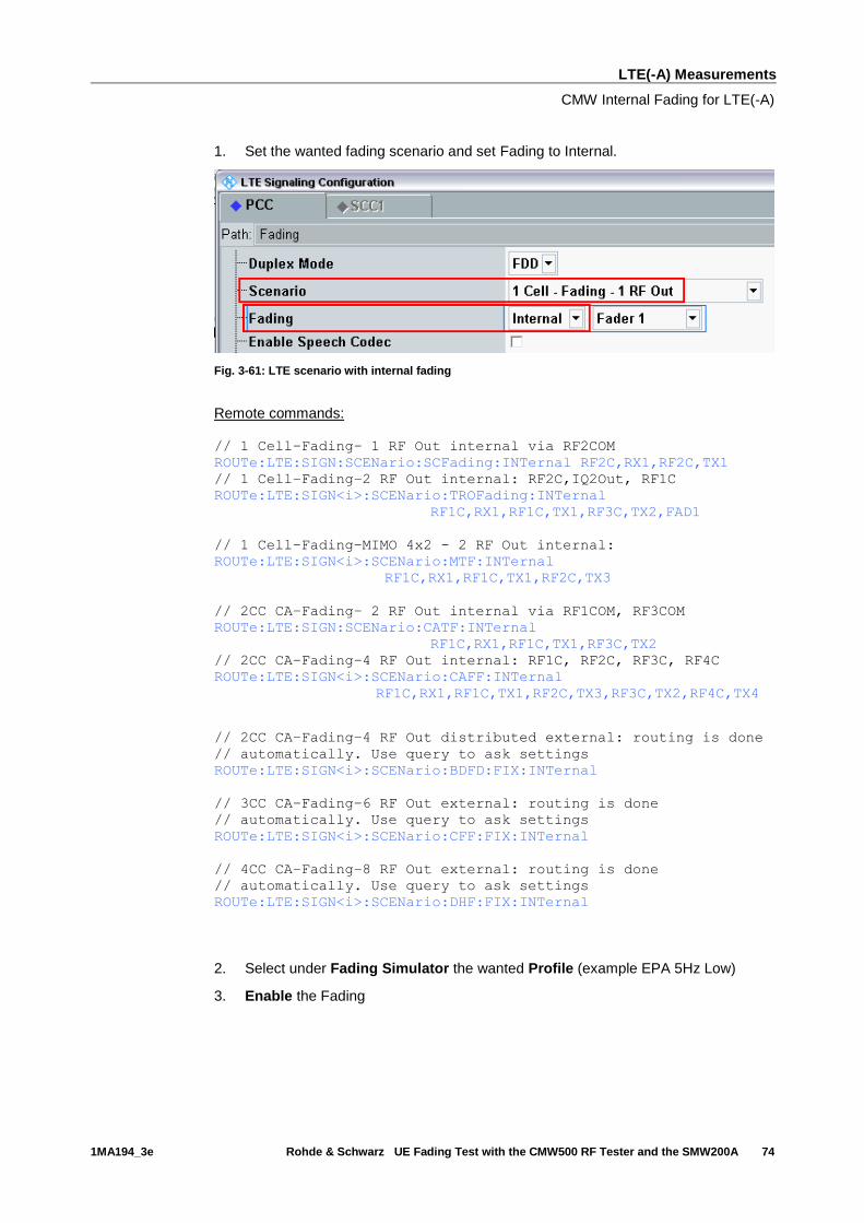
1. Set the wanted fading scenario and set Fading to Internal.
Fig. 3-61: LTE scenario with internal fading
Remote commands:
// 1 Cell–Fading– 1 RF Out internal via RF2COM
ROUTe:LTE:SIGN:SCENario:SCFading:INTernal RF2C,RX1,RF2C,TX1
// 1 Cell–Fading–2 RF Out internal: RF2C,IQ2Out, RF1C
ROUTe:LTE:SIGN<i>:SCENario:TROFading:INTernal
RF1C,RX1,RF1C,TX1,RF3C,TX2,FAD1
// 1 Cell–Fading–MIMO 4x2 - 2 RF Out internal:
ROUTe:LTE:SIGN<i>:SCENario:MTF:INTernal
RF1C,RX1,RF1C,TX1,RF2C,TX3
// 2CC CA–Fading– 2 RF Out internal via RF1COM, RF3COM
ROUTe:LTE:SIGN:SCENario:CATF:INTernal
RF1C,RX1,RF1C,TX1,RF3C,TX2
// 2CC CA–Fading–4 RF Out internal: RF1C, RF2C, RF3C, RF4C
ROUTe:LTE:SIGN<i>:SCENario:CAFF:INTernal
RF1C,RX1,RF1C,TX1,RF2C,TX3,RF3C,TX2,RF4C,TX4
// 2CC CA–Fading–4 RF Out distributed external: routing is done
// automatically. Use query to ask settings
ROUTe:LTE:SIGN<i>:SCENario:BDFD:FIX:INTernal
// 3CC CA–Fading–6 RF Out external: routing is done
// automatically. Use query to ask settings
ROUTe:LTE:SIGN<i>:SCENario:CFF:FIX:INTernal
// 4CC CA–Fading–8 RF Out external: routing is done
// automatically. Use query to ask settings
ROUTe:LTE:SIGN<i>:SCENario:DHF:FIX:INTernal
2. Select under Fading Simulator the wanted Profile (example EPA 5Hz Low)
3. Enable the Fading

LTE(-A) Measurements
CMW Internal Fading for LTE(-A)
1MA194_3e Rohde & Schwarz UE Fading Test with the CMW500 RF Tester and the SMW200A 75
Fig. 3-62: internal LTE fading profiles
Remote commands:
// Fading profile EPA 56 Hz low
CONFigure:LTE:SIGN<i>:FADing[:PCC]:FSIMulator:STANdard EP5Low
CONFigure:LTE:SIGN<i>:FADing:SCC:FSIMulator:STANdard EP5Low
// Switch on FAding
CONFigure:LTE:SIGN<i>[:PCC]:FADing:FSIMulator:ENABle ON
CONFigure:LTE:SIGN<i>:SCC:FADing:FSIMulator:ENABle ON
4. If wanted, apply AWGN by setting the Signal/Noise-ratio and enable the AWGN.
Fig. 3-63: internal LTE AWGN section
Remote commands:
// Ratio 1.5
CONFigure:LTE:SIGN<i>:FADing[:PCC]:AWGN:BWIDth:RATio 1.5
CONFigure:LTE:SIGN<i>:FADing:SCC:AWGN:BWIDth:RATio 1.5
// Signal/Noise 5.0
CONFigure:LTE:SIGN<i>:FADing[:PCC]:AWGN:SNRatio 5.0
CONFigure:LTE:SIGN<i>:FADing:SCC]:AWGN:SNRatio 5.0
// Switch on AWGN
CONFigure:LTE:SIGN<i>:FADing[:PCC]:AWGN:ENABle ON
CONFigure:LTE:SIGN<i>:FADing:SCC:AWGN:ENABle ON
5. Start the measurement (see 3.1).

W-CDMA and HSPA(+) Measurements
CMW Internal Fading for LTE(-A)
1MA194_3e Rohde & Schwarz UE Fading Test with the CMW500 RF Tester and the SMW200A 76
4 W-CDMA and HSPA(+) Measurements
With the W-CDMA standard, UE receiver measurements include different types of
measurements depending on the release:
W-CDMA Rx measurements
Release Name Measurement
DL / UL Carrier
99 RMC 1 / 1 BER
5 HSDPA 1 / 1 HSDPA ACK (BLER)
6 HSUPA 1 / 1 E-HICH
7 HSPA+ 1 / 1 HSDPA ACK (BLER)
8 Dual Cell HSDPA 2 /1 HSDPA ACK (BLER)
9 DC-HSUPA 2 / 2 E-HICH
Dual-Band HSDPA 2 / 1 HSDPA ACK (BLER)
10 Four Carrier HSDPA CMW: 3 / 2 HSDPA ACK (BLER)
All measurements are summarized in the WCDMA RX Meas test and measurement
applications (see 4.1).
Before the start of the W-CDMA signaling, external fading must be selected as the
scenario. Once signaling has begun, or once a connection has been established with
the DUT, it is no longer possible to change scenarios.
Different antenna configurations are possible with W-CDMA. They also require
different ways of handling fading:
W-CDMA scenarios
W-CDMA
scenario
Purpose Release CMW configuration
SISO Standard 99/5/6/7 Standard cell fading
SIMO Rx Diversity 99/5/6/7 Standard cell Rx Diversity fading
Dual Carrier DC-HSPA+ 5/7/8 Dual Carrier Fading
DC – SIMO DC-HSPA+ with RX Diversity 5/7/8 Dual Carrier Rx Diversity Fading
Dual Band DB-DC-HSDPA+ 5/7/8/9 Dual Carrier / Dual Band Fading
Dual Band - SIMO DB-DC-HSDPA+ with RX Diversity 5/7/8/9 Dual Carrier / Dual Band Fading
Rx Diversity
Table 4-1: W-CDMA scenarios in the CMW.
This section describes the steps required to perform a W-CDMA Rx measurement
under several different conditions, such as SISO or DC-HSPA+ fading.
For more information on W-CDMA signaling or on W-CDMA Rx measurements, refer
to [6].
Important note: The CMW and the SMW use DigIQ connections to exchange the
signals. The correct setting of the crest factor is essential for the fading and the correct
RF level handling (see sections 4.2 to 4.5). The crest factor of the CMW depends on
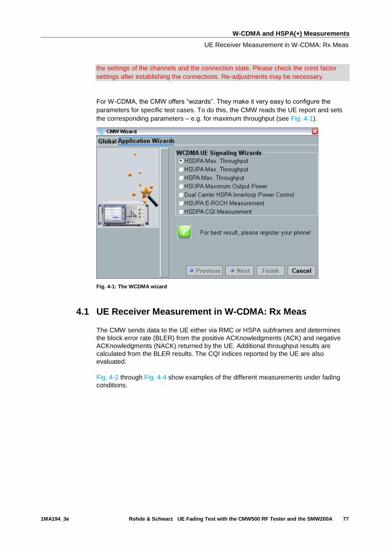
W-CDMA and HSPA(+) Measurements
UE Receiver Measurement in W-CDMA: Rx Meas
1MA194_3e Rohde & Schwarz UE Fading Test with the CMW500 RF Tester and the SMW200A 77
the settings of the channels and the connection state. Please check the crest factor
settings after establishing the connections. Re-adjustments may be necessary.
For W-CDMA, the CMW offers “wizards”. They make it very easy to configure the
parameters for specific test cases. To do this, the CMW reads the UE report and sets
the corresponding parameters – e.g. for maximum throughput (see Fig. 4-1).
Fig. 4-1: The WCDMA wizard
4.1 UE Receiver Measurement in W-CDMA: Rx Meas
The CMW sends data to the UE either via RMC or HSPA subframes and determines
the block error rate (BLER) from the positive ACKnowledgments (ACK) and negative
ACKnowledgments (NACK) returned by the UE. Additional throughput results are
calculated from the BLER results. The CQI indices reported by the UE are also
evaluated.
Fig. 4-2 through Fig. 4-4 show examples of the different measurements under fading
conditions.

W-CDMA and HSPA(+) Measurements
UE Receiver Measurement in W-CDMA: Rx Meas
1MA194_3e Rohde & Schwarz UE Fading Test with the CMW500 RF Tester and the SMW200A 78
BER
Fig. 4-2: W-CDMA BER Measurement on DCH (RMC) Rel 99. The UE loops back the data stream sent
from the CMW. The CMW determines the bit error rate (BER) and from that also determines the block
error rates.
Remote commands:
CONFigure:WCDMa:SIGN<i>:BER:TBLocks 10000 // set 10000 blocks
INITiate:WCDMa:SIGN<i>:BER // start measurement
FETCh:WCDMa:SIGN<i>:BER? // get results
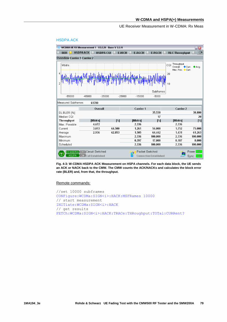
W-CDMA and HSPA(+) Measurements
UE Receiver Measurement in W-CDMA: Rx Meas
1MA194_3e Rohde & Schwarz UE Fading Test with the CMW500 RF Tester and the SMW200A 79
HSDPA ACK
Fig. 4-3: W-CDMA HSDPA ACK Measurement on HSPA channels. For each data block, the UE sends
an ACK or NACK back to the CMW. The CMW counts the ACK/NACKs and calculates the block error
rate (BLER) and, from that, the throughput.
Remote commands:
//set 10000 subframes
CONFigure:WCDMa:SIGN<i>:HACK:MSFRames 10000
// start measurement
INITiate:WCDMa:SIGN<i>:HACK
// get results
FETCh:WCDMa:SIGN<i>:HACK:TRACe:THRoughput:TOTal:CURRent?
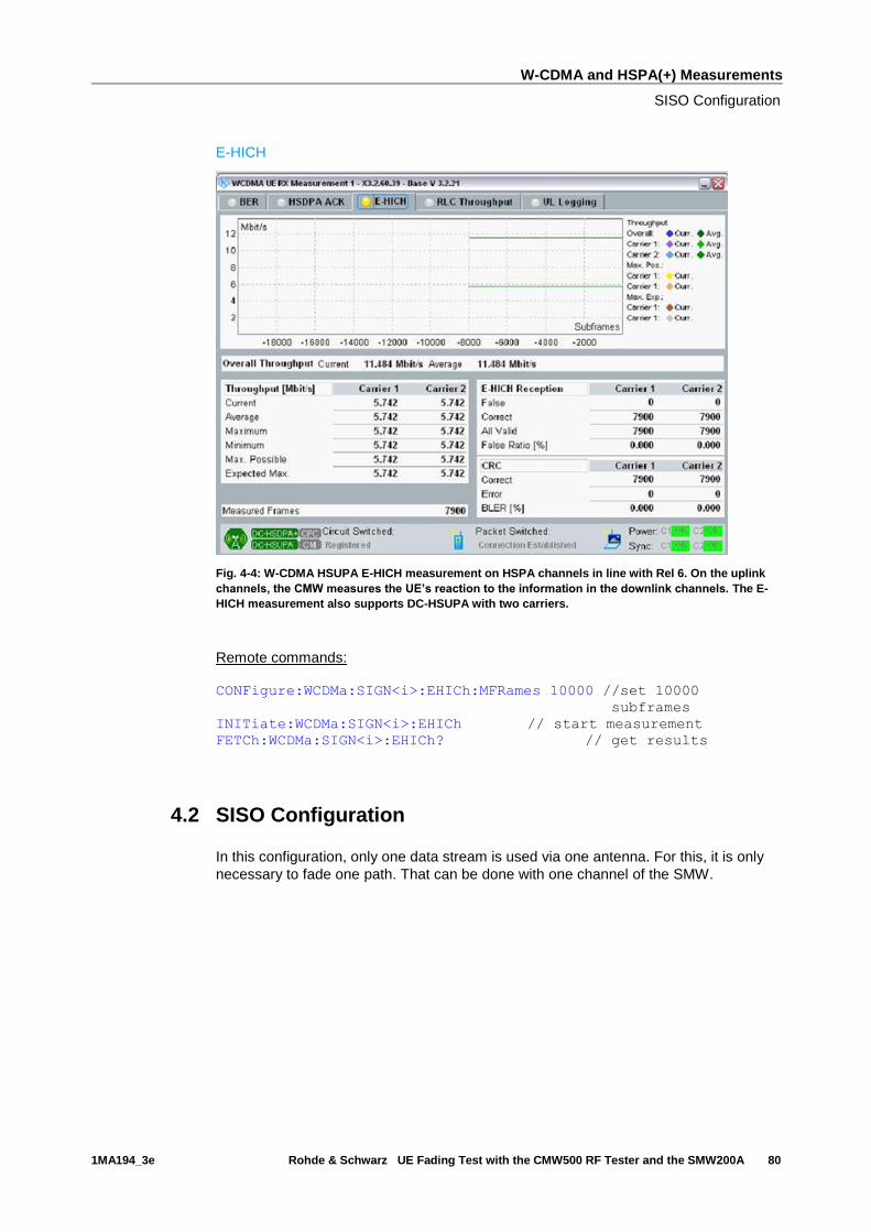
W-CDMA and HSPA(+) Measurements
SISO Configuration
1MA194_3e Rohde & Schwarz UE Fading Test with the CMW500 RF Tester and the SMW200A 80
E-HICH
Fig. 4-4: W-CDMA HSUPA E-HICH measurement on HSPA channels in line with Rel 6. On the uplink
channels, the CMW measures the UE’s reaction to the information in the downlink channels. The E-
HICH measurement also supports DC-HSUPA with two carriers.
Remote commands:
CONFigure:WCDMa:SIGN<i>:EHICh:MFRames 10000 //set 10000
subframes
INITiate:WCDMa:SIGN<i>:EHICh // start measurement
FETCh:WCDMa:SIGN<i>:EHICh? // get results
4.2 SISO Configuration
In this configuration, only one data stream is used via one antenna. For this, it is only
necessary to fade one path. That can be done with one channel of the SMW.

W-CDMA and HSPA(+) Measurements
SISO Configuration
1MA194_3e Rohde & Schwarz UE Fading Test with the CMW500 RF Tester and the SMW200A 81
Fig. 4-5: Block diagram for the SISO test setup.
1. In the WCDMA Signaling Configuration, select the Standard Cell Fading
Scenario (see Fig. 4-6). Set Fading to External.
Fig. 4-6: WCDMA scenario for SISO: Standard Cell Fading. The CMW indicates the crest factor that is
entered in the SMW Dig IQ Input.
Remote commands:
// Standard Cell Fading external with RF2C and IQ 2
ROUTe:WCDMa:SIGN:SCENario:SCFading RF2C,RX1,RF2C,TX1,IQ2O
// read out IQ settings
SENSe:WCDMa:SIGN<i>:IQOut:CARRier<carrier>?
2. Take note of the Crest Factor under IQ Out and enter this value in the SMW
under Baseband Input Level (see Fig. 2-13 in section 2.3).
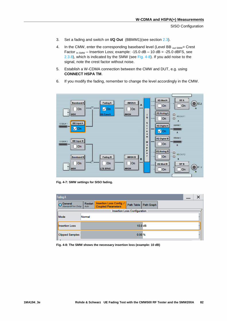
W-CDMA and HSPA(+) Measurements
SISO Configuration
1MA194_3e Rohde & Schwarz UE Fading Test with the CMW500 RF Tester and the SMW200A 82
3. Set a fading and switch on I/Q Out (BBMM1)(see section 2.3).
4. In the CMW, enter the corresponding baseband level (Level BB out SMW= Crest
Factor In SMW – Insertion Loss; example: -15.0 dB – 10 dB = -25.0 dBFS, see
2.3.8), which is indicated by the SMW (see Fig. 4-8). If you add noise to the
signal, note the crest factor without noise.
5. Establish a W-CDMA connection between the CMW and DUT, e.g. using
CONNECT HSPA TM.
6. If you modify the fading, remember to change the level accordingly in the CMW.
Fig. 4-7: SMW settings for SISO fading.
Fig. 4-8: The SMW shows the necessary insertion loss (example: 10 dB)
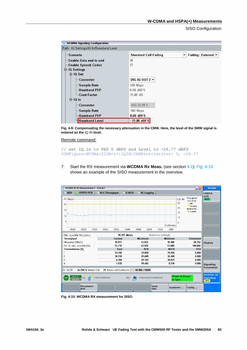
W-CDMA and HSPA(+) Measurements
SISO Configuration
1MA194_3e Rohde & Schwarz UE Fading Test with the CMW500 RF Tester and the SMW200A 83
Fig. 4-9: Compensating the necessary attenuation in the CMW. Here, the level of the SMW signal is
entered as the IQ IN level.
Remote command:
// set IQ in to PEP 0 dBFS and Level to -26.77 dBFS CONFigure:WCDMa:SIGN<i>:IQIN:CARRier<carrier> 0, -26.77
7. Start the RX measurement via WCDMA Rx Meas. (see section 4.1). Fig. 4-10
shows an example of the SISO measurement in the overview.
Fig. 4-10: WCDMA RX measurement for SISO.

W-CDMA and HSPA(+) Measurements
Rx Diversity Configuration (SIMO)
1MA194_3e Rohde & Schwarz UE Fading Test with the CMW500 RF Tester and the SMW200A 84
4.3 Rx Diversity Configuration (SIMO)
Rx Diversity simulates the two different receiving paths of the UE. The second path is
provided by the CMW via RFCOM2.
Fig. 4-11: Block diagram for the Rx Diversity test setup. One carrier is split up in two paths and
transmitted via two antennas and with different fading.
1. In the WCDMA Signaling Configuration, select the Standard Cell Rx Diversity
Fading Scenario (see Fig. 4-18). Set Fading to External. The CMW can
accommodate different antenna configurations for the UE. Output for the second
carrier can either be provided through the same RF port or through a separate
one.
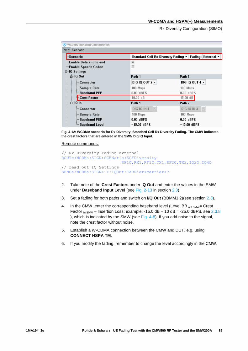
W-CDMA and HSPA(+) Measurements
Rx Diversity Configuration (SIMO)
1MA194_3e Rohde & Schwarz UE Fading Test with the CMW500 RF Tester and the SMW200A 85
Fig. 4-12: WCDMA scenario for Rx Diversity: Standard Cell Rx Diversity Fading. The CMW indicates
the crest factors that are entered in the SMW Dig IQ Input.
Remote commands:
// Rx Diversity Fading external
ROUTe:WCDMa:SIGN:SCENario:SCFDiversity
RF1C,RX1,RF1C,TX1,RF2C,TX2,IQ2O,IQ4O
// read out IQ Settings
SENSe:WCDMa:SIGN<i>:IQOut:CARRier<carrier>?
2. Take note of the Crest Factors under IQ Out and enter the values in the SMW
under Baseband Input Level (see Fig. 2-13 in section 2.3).
3. Set a fading for both paths and switch on I/Q Out (BBMM1|2)(see section 2.3).
4. In the CMW, enter the corresponding baseband level (Level BB out SMW= Crest
Factor In SMW – Insertion Loss; example: -15.0 dB – 10 dB = -25.0 dBFS, see 2.3.8
), which is indicated by the SMW (see Fig. 4-8). If you add noise to the signal,
note the crest factor without noise.
5. Establish a W-CDMA connection between the CMW and DUT, e.g. using
CONNECT HSPA TM.
6. If you modify the fading, remember to change the level accordingly in the CMW.

W-CDMA and HSPA(+) Measurements
Rx Diversity Configuration (SIMO)
1MA194_3e Rohde & Schwarz UE Fading Test with the CMW500 RF Tester and the SMW200A 86
Fig. 4-13: SMW settings for fading two paths.
Fig. 4-14: The SMW shows the necessary insertion loss (example: 10 dB)
Fig. 4-15: Compensating for the necessary attenuation in the CMW. Here, the levels of the SMW
signals are entered as the IQ In level.

W-CDMA and HSPA(+) Measurements
Dual-Carrier Configuration (DC-HSPA+)
1MA194_3e Rohde & Schwarz UE Fading Test with the CMW500 RF Tester and the SMW200A 87
Remote command:
// set IQ in to PEP 0 dBFS and Level to -25.0 dBFS CONFigure:WCDMa:SIGN<i>:IQIN:CARRier1 0, -25.0
CONFigure:WCDMa:SIGN<i>:IQIN:CARRier2 0, -25.0
7. Start the RX measurement via WCDMA Rx Meas. (see section 4.1).
4.4 Dual-Carrier Configuration (DC-HSPA+)
With the DC-HSPA+ sceanrio, two different carriers are transmitted via two antennas in
order to increase the data throughput. For the simulation, it is necessary to use two
fading paths in this case. To enable two downlink carriers, use H-SETs with the suffix
A, e.g H-SET 3A.
Fig. 4-16: Block diagram for the DC-HSPA test setup. Two carriers are transmitted via two antennas
and with different fading. With the CMW, two different RF connectors can be used or the signal can
be provided at one output port.
1. In the WCDMA Signaling Configuration, select the Dual Carrier Fading
Scenario (see Fig. 4-18). Set Fading to External. The CMW can accommodate
different antenna configurations for the UE. Output for the second carrier can
either be provided through the same RF port or through a separate one.
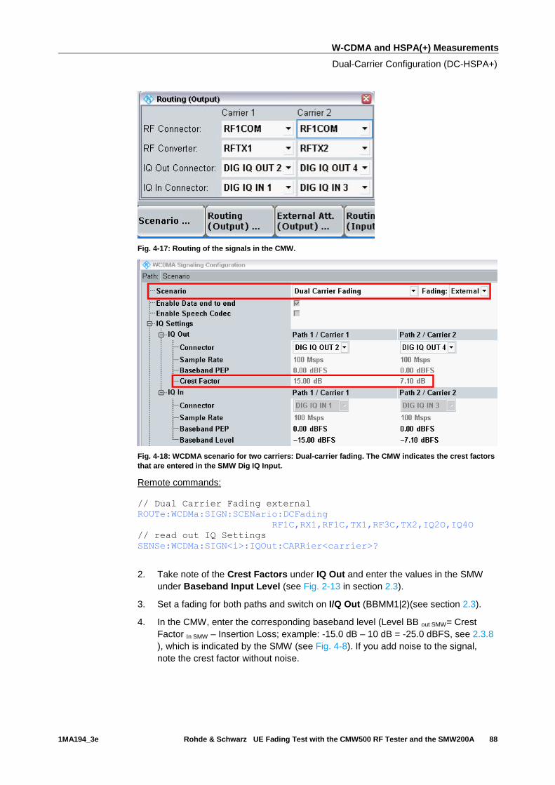
W-CDMA and HSPA(+) Measurements
Dual-Carrier Configuration (DC-HSPA+)
1MA194_3e Rohde & Schwarz UE Fading Test with the CMW500 RF Tester and the SMW200A 88
Fig. 4-17: Routing of the signals in the CMW.
Fig. 4-18: WCDMA scenario for two carriers: Dual-carrier fading. The CMW indicates the crest factors
that are entered in the SMW Dig IQ Input.
Remote commands:
// Dual Carrier Fading external
ROUTe:WCDMa:SIGN:SCENario:DCFading
RF1C,RX1,RF1C,TX1,RF3C,TX2,IQ2O,IQ4O
// read out IQ Settings
SENSe:WCDMa:SIGN<i>:IQOut:CARRier<carrier>?
2. Take note of the Crest Factors under IQ Out and enter the values in the SMW
under Baseband Input Level (see Fig. 2-13 in section 2.3).
3. Set a fading for both paths and switch on I/Q Out (BBMM1|2)(see section 2.3).
4. In the CMW, enter the corresponding baseband level (Level BB out SMW= Crest
Factor In SMW – Insertion Loss; example: -15.0 dB – 10 dB = -25.0 dBFS, see 2.3.8
), which is indicated by the SMW (see Fig. 4-8). If you add noise to the signal,
note the crest factor without noise.
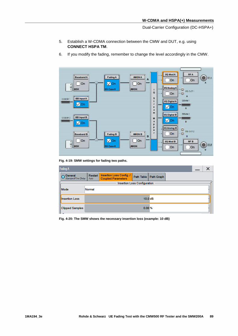
W-CDMA and HSPA(+) Measurements
Dual-Carrier Configuration (DC-HSPA+)
1MA194_3e Rohde & Schwarz UE Fading Test with the CMW500 RF Tester and the SMW200A 89
5. Establish a W-CDMA connection between the CMW and DUT, e.g. using
CONNECT HSPA TM.
6. If you modify the fading, remember to change the level accordingly in the CMW.
Fig. 4-19: SMW settings for fading two paths.
Fig. 4-20: The SMW shows the necessary insertion loss (example: 10 dB)

W-CDMA and HSPA(+) Measurements
Dual-Carrier Configuration (DC-HSPA+)
1MA194_3e Rohde & Schwarz UE Fading Test with the CMW500 RF Tester and the SMW200A 90
Fig. 4-21: Compensating for the necessary attenuation in the CMW. Here, the levels of the SMW
signals are entered as the IQ In level.
Remote command:
// set IQ in to PEP 0 dBFS and Level to -25.0 dBFS CONFigure:WCDMa:SIGN<i>:IQIN:CARRier1 0, -25.0
CONFigure:WCDMa:SIGN<i>:IQIN:CARRier2 0, -17.1
7. Start the RX measurement via WCDMA Rx Meas. (see section 4.1). Fig. 4-22
shows an example of the DC-HSPA measurement in the overview.
Fig. 4-22: WCDMA RX measurement for DC-HSPA. The measurements are adapted automatically for
both streams individually and as an overall assessment.

W-CDMA and HSPA(+) Measurements
DC-HSPA+ with Rx Diversity Configuration
1MA194_3e Rohde & Schwarz UE Fading Test with the CMW500 RF Tester and the SMW200A 91
4.5 DC-HSPA+ with Rx Diversity Configuration
With the DC-HSPA+ scenario, two different carriers are transmitted via two antennas in
order to increase the data throughput. Here, too, it is possible to simulate the RX
diversity reception. Since it is necessary to simulate two carriers for two antennas
each, four fading paths are required in this case. The four paths are made available via
the SMW’s 2x2 MIMO function. However, this is NOT a MIMO function in W-CDMA! To
enable two downlink carriers, use H-SETs with the suffix A, e.g H-SET 3A.
Fig. 4-23: Block diagram for the DC-HSPA test setup with RX diversity. Two carriers are transmitted
via two antennas and with different fading. The UE’s RX diversity antenna is operated via RF2COM.
Fig. 4-24: Generating Rx diversity for dual carriers: Both carrier signals are generated in the CMW’s
baseband signaling unit (with a frequency of 0 Hz), the second signal is offset by 5 MHz in the
baseband. Due to the cross components (MIMO function), both carrier signals are available on both
of the SMW’s paths. In the CMW, both paths are modulated to the carrier frequency f1.
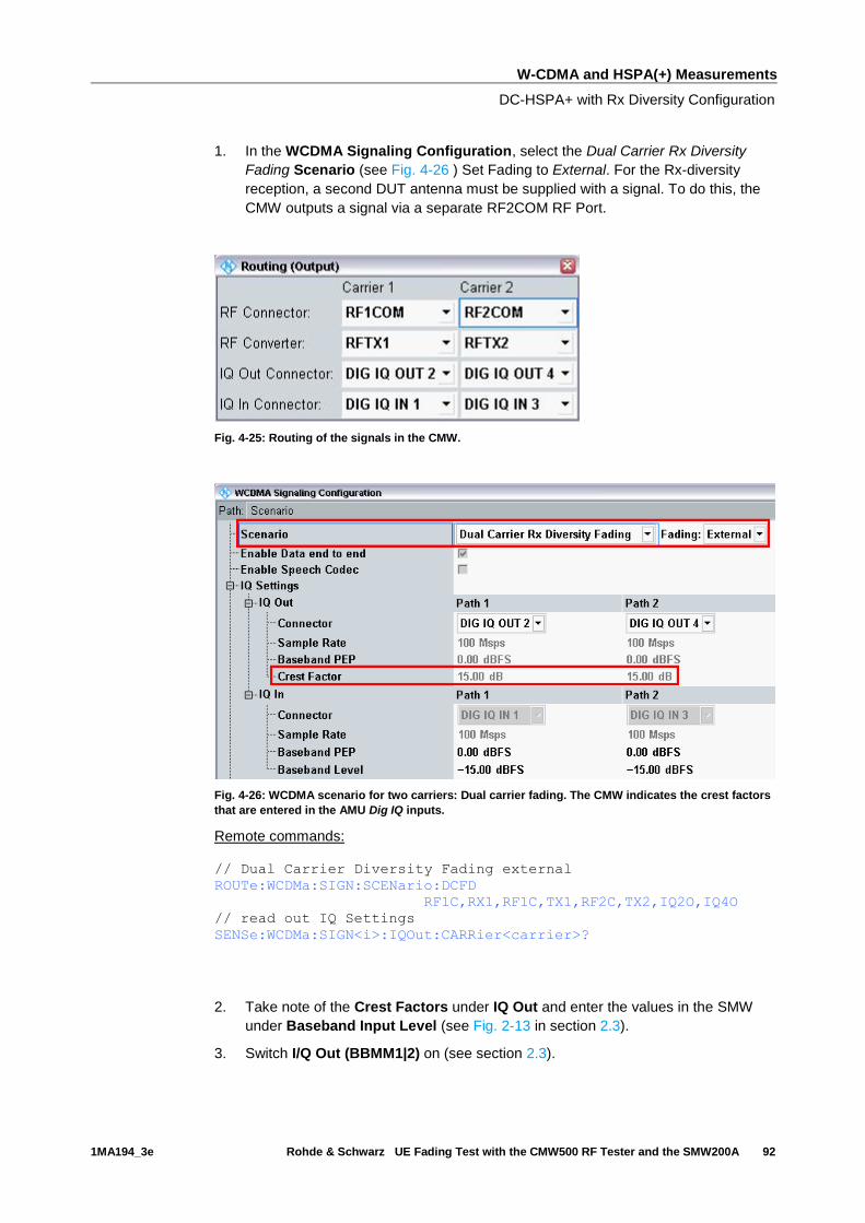
W-CDMA and HSPA(+) Measurements
DC-HSPA+ with Rx Diversity Configuration
1MA194_3e Rohde & Schwarz UE Fading Test with the CMW500 RF Tester and the SMW200A 92
1. In the WCDMA Signaling Configuration, select the Dual Carrier Rx Diversity
Fading Scenario (see Fig. 4-26 ) Set Fading to External. For the Rx-diversity
reception, a second DUT antenna must be supplied with a signal. To do this, the
CMW outputs a signal via a separate RF2COM RF Port.
Fig. 4-25: Routing of the signals in the CMW.
Fig. 4-26: WCDMA scenario for two carriers: Dual carrier fading. The CMW indicates the crest factors
that are entered in the AMU Dig IQ inputs.
Remote commands:
// Dual Carrier Diversity Fading external
ROUTe:WCDMa:SIGN:SCENario:DCFD
RF1C,RX1,RF1C,TX1,RF2C,TX2,IQ2O,IQ4O
// read out IQ Settings
SENSe:WCDMa:SIGN<i>:IQOut:CARRier<carrier>?
2. Take note of the Crest Factors under IQ Out and enter the values in the SMW
under Baseband Input Level (see Fig. 2-13 in section 2.3).
3. Switch I/Q Out (BBMM1|2) on (see section 2.3).

W-CDMA and HSPA(+) Measurements
DC-HSPA+ with Rx Diversity Configuration
1MA194_3e Rohde & Schwarz UE Fading Test with the CMW500 RF Tester and the SMW200A 93
4. The four paths are realized using the SMW’s 2x2-MIMO function. In addition,
select the fading. This fading value is automatically used for all four paths. Set the
virtual RF frequency to the mid-point between the two carriers. (Example: Carrier
1 at 2112.6 MHz and Carrier 2 at 2117.6 MHz -> Virtual frequency at
2115.1 MHz).
5. Set an offset of 5 MHz in the second path.
6. In the CMW, enter the corresponding baseband level (Level BB out SMW= Crest
Factor In SMW – Insertion Loss; example: -15.0 dB – 16 dB = -31.0 dBFS, see 2.3.8
), which is indicated by the SMW (see Fig. 4-8). If you add noise to the signal,
note the crest factor without noise.
7. Establish a W-CDMA connection between the CMW and DUT, e.g. using
CONNECT HSPA TM.
8. If you modify the fading, remember to change the level accordingly in the CMW.
Fig. 4-27: SMW settings for dual carriers for Rx diversity: Fading of four paths. The second path must
be offset by 5 MHz.
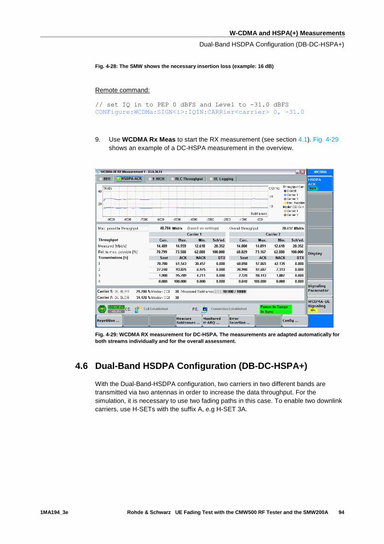
W-CDMA and HSPA(+) Measurements
Dual-Band HSDPA Configuration (DB-DC-HSPA+)
1MA194_3e Rohde & Schwarz UE Fading Test with the CMW500 RF Tester and the SMW200A 94
Fig. 4-28: The SMW shows the necessary insertion loss (example: 16 dB)
Remote command:
// set IQ in to PEP 0 dBFS and Level to -31.0 dBFS CONFigure:WCDMa:SIGN<i>:IQIN:CARRier<carrier> 0, -31.0
9. Use WCDMA Rx Meas to start the RX measurement (see section 4.1). Fig. 4-29
shows an example of a DC-HSPA measurement in the overview.
Fig. 4-29: WCDMA RX measurement for DC-HSPA. The measurements are adapted automatically for
both streams individually and for the overall assessment.
4.6 Dual-Band HSDPA Configuration (DB-DC-HSPA+)
With the Dual-Band-HSDPA configuration, two carriers in two different bands are
transmitted via two antennas in order to increase the data throughput. For the
simulation, it is necessary to use two fading paths in this case. To enable two downlink
carriers, use H-SETs with the suffix A, e.g H-SET 3A.
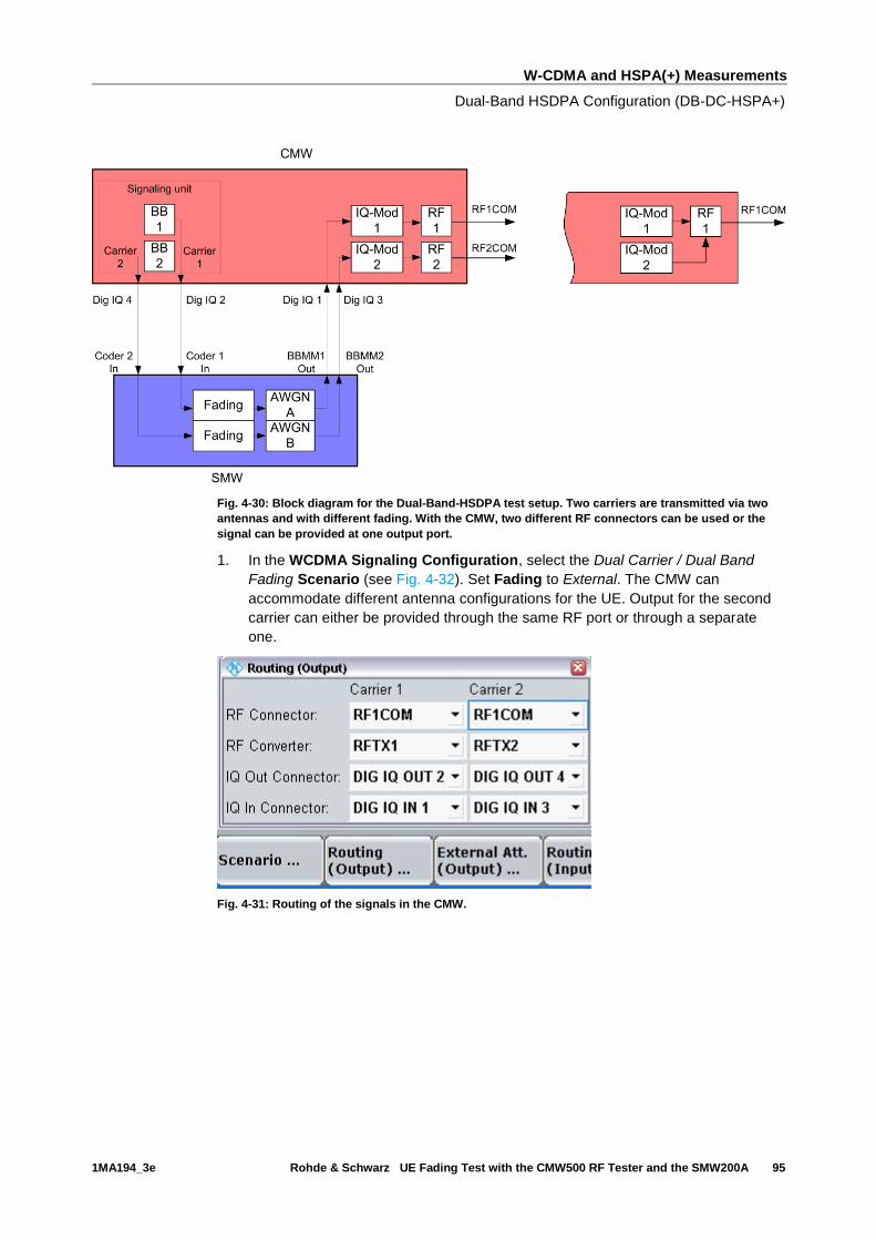
W-CDMA and HSPA(+) Measurements
Dual-Band HSDPA Configuration (DB-DC-HSPA+)
1MA194_3e Rohde & Schwarz UE Fading Test with the CMW500 RF Tester and the SMW200A 95
Fig. 4-30: Block diagram for the Dual-Band-HSDPA test setup. Two carriers are transmitted via two
antennas and with different fading. With the CMW, two different RF connectors can be used or the
signal can be provided at one output port.
1. In the WCDMA Signaling Configuration, select the Dual Carrier / Dual Band
Fading Scenario (see Fig. 4-32). Set Fading to External. The CMW can
accommodate different antenna configurations for the UE. Output for the second
carrier can either be provided through the same RF port or through a separate
one.
Fig. 4-31: Routing of the signals in the CMW.
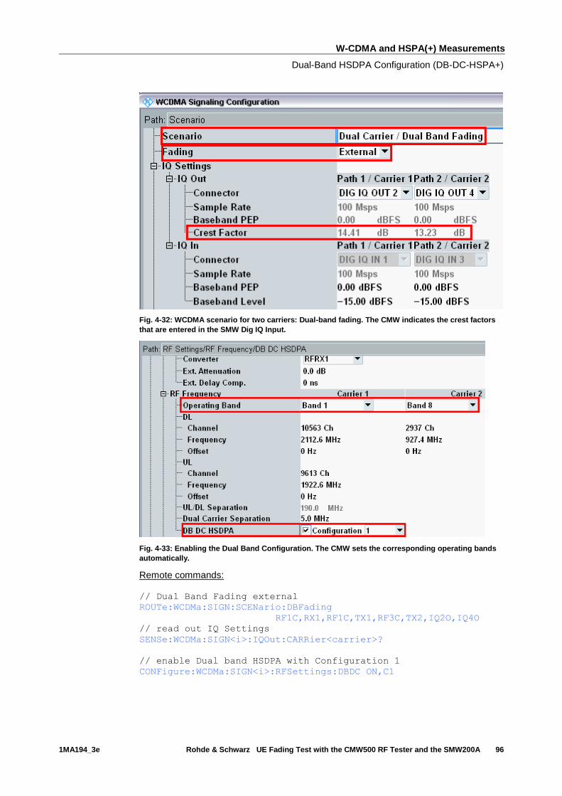
W-CDMA and HSPA(+) Measurements
Dual-Band HSDPA Configuration (DB-DC-HSPA+)
1MA194_3e Rohde & Schwarz UE Fading Test with the CMW500 RF Tester and the SMW200A 96
Fig. 4-32: WCDMA scenario for two carriers: Dual-band fading. The CMW indicates the crest factors
that are entered in the SMW Dig IQ Input.
Fig. 4-33: Enabling the Dual Band Configuration. The CMW sets the corresponding operating bands
automatically.
Remote commands:
// Dual Band Fading external
ROUTe:WCDMa:SIGN:SCENario:DBFading
RF1C,RX1,RF1C,TX1,RF3C,TX2,IQ2O,IQ4O
// read out IQ Settings
SENSe:WCDMa:SIGN<i>:IQOut:CARRier<carrier>?
// enable Dual band HSDPA with Configuration 1
CONFigure:WCDMa:SIGN<i>:RFSettings:DBDC ON,C1
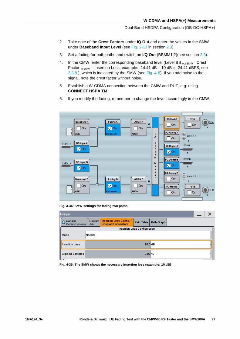
W-CDMA and HSPA(+) Measurements
Dual-Band HSDPA Configuration (DB-DC-HSPA+)
1MA194_3e Rohde & Schwarz UE Fading Test with the CMW500 RF Tester and the SMW200A 97
2. Take note of the Crest Factors under IQ Out and enter the values in the SMW
under Baseband Input Level (see Fig. 2-13 in section 2.3).
3. Set a fading for both paths and switch on I/Q Out (BBMM1|2)(see section 2.3).
4. In the CMW, enter the corresponding baseband level (Level BB out SMW= Crest
Factor In SMW – Insertion Loss; example: -14.41 dB – 10 dB = -24.41 dBFS, see
2.3.8 ), which is indicated by the SMW (see Fig. 4-8). If you add noise to the
signal, note the crest factor without noise.
5. Establish a W-CDMA connection between the CMW and DUT, e.g. using
CONNECT HSPA TM.
6. If you modify the fading, remember to change the level accordingly in the CMW.
Fig. 4-34: SMW settings for fading two paths.
Fig. 4-35: The SMW shows the necessary insertion loss (example: 10 dB)

W-CDMA and HSPA(+) Measurements
Dual-Band HSDPA Configuration (DB-DC-HSPA+)
1MA194_3e Rohde & Schwarz UE Fading Test with the CMW500 RF Tester and the SMW200A 98
Fig. 4-36: Compensating for the necessary attenuation in the CMW. Here, the levels of the SMW
signals are entered as the IQ In level.
Remote command:
// set IQ in to PEP 0 dBFS and Level to -24.41 dBFS CONFigure:WCDMa:SIGN<i>:IQIN:CARRier1 0, -24.41
CONFigure:WCDMa:SIGN<i>:IQIN:CARRier2 0, -23.23
7. Start the RX measurement via WCDMA Rx Meas. (see section 4.1). Fig. 4-22
shows an example of the Dual-Band HSPSA measurement in the overview.
Fig. 4-37: WCDMA RX measurement for Dual-Band-HSPDA. The measurements are adapted
automatically for both streams individually and as an overall assessment.

W-CDMA and HSPA(+) Measurements
Dual Band HSDPA with Rx Diversity Configuration (DB-DC-HSPA+ with Rx
Diversity)
1MA194_3e Rohde & Schwarz UE Fading Test with the CMW500 RF Tester and the SMW200A 99
4.7 Dual Band HSDPA with Rx Diversity Configuration
(DB-DC-HSPA+ with Rx Diversity)
With the Dual-Band HSPDA configuration, two different carriers are transmitted via two
antennas in order to increase the data throughput. Here, too, it is possible to simulate
the RX diversity reception. Since it is necessary to simulate two carriers for two
antennas each, four fading paths are required in this case. The four paths are faded in
the SMW. To enable two downlink carriers, use H-SETs with the suffix A, e.g H-SET
3A.
Fig. 4-38: Block diagram for the Dual-Band-HSDPA test setup with RX diversity. Two carriers are
transmitted via two antennas and with different fading. The UE’s RX diversity antenna is operated via
RF2COM.
1. In the WCDMA Signaling Configuration, select the Dual Carrier / Dual Band Rx
Diversity Fading Scenario (see Fig. 4-40) Set Fading to External. For the Rx-
diversity reception, a second DUT antenna must be supplied with the two carrier
signals. To do this, the CMW allows flexible output routing.
Fig. 4-39: Routing of the signals in the CMW. In this case, RxDiv signal of carrier 1 is routed to
RF3COM, RxDiv signal of carrier 2 is routed to RF4COM.
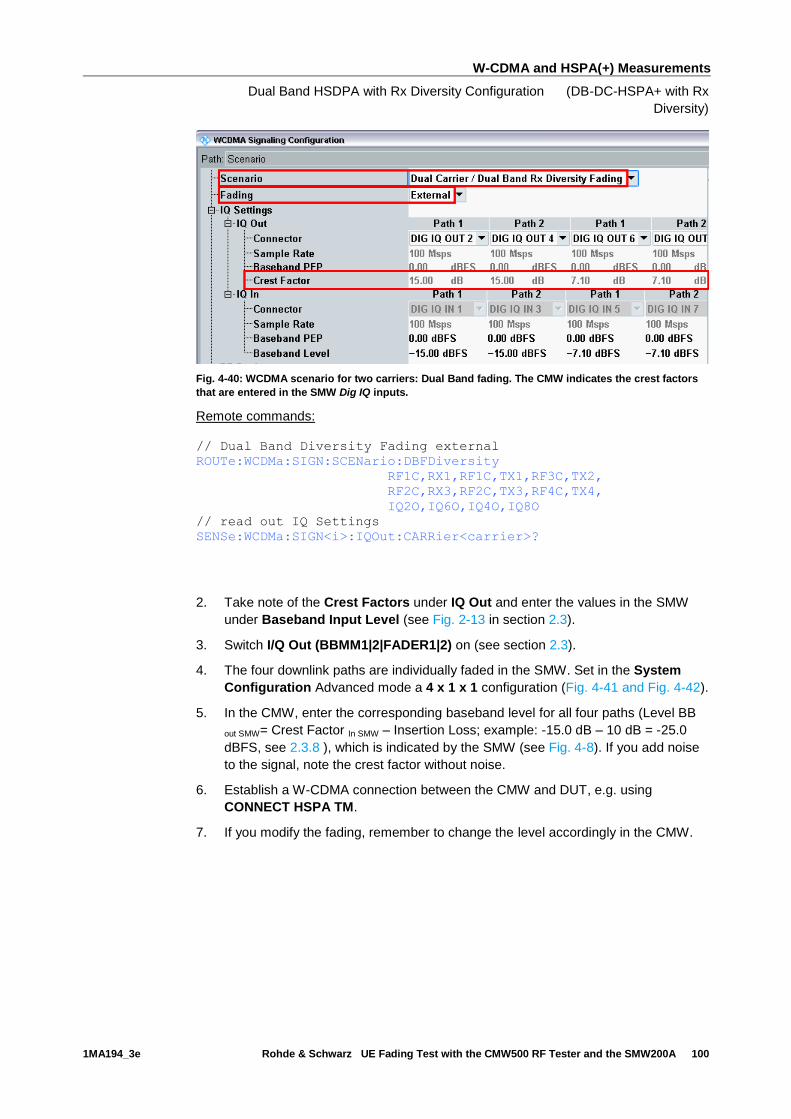
W-CDMA and HSPA(+) Measurements
Dual Band HSDPA with Rx Diversity Configuration (DB-DC-HSPA+ with Rx
Diversity)
1MA194_3e Rohde & Schwarz UE Fading Test with the CMW500 RF Tester and the SMW200A 100
Fig. 4-40: WCDMA scenario for two carriers: Dual Band fading. The CMW indicates the crest factors
that are entered in the SMW Dig IQ inputs.
Remote commands:
// Dual Band Diversity Fading external
ROUTe:WCDMa:SIGN:SCENario:DBFDiversity
RF1C,RX1,RF1C,TX1,RF3C,TX2,
RF2C,RX3,RF2C,TX3,RF4C,TX4,
IQ2O,IQ6O,IQ4O,IQ8O
// read out IQ Settings
SENSe:WCDMa:SIGN<i>:IQOut:CARRier<carrier>?
2. Take note of the Crest Factors under IQ Out and enter the values in the SMW
under Baseband Input Level (see Fig. 2-13 in section 2.3).
3. Switch I/Q Out (BBMM1|2|FADER1|2) on (see section 2.3).
4. The four downlink paths are individually faded in the SMW. Set in the System
Configuration Advanced mode a 4 x 1 x 1 configuration (Fig. 4-41 and Fig. 4-42).
5. In the CMW, enter the corresponding baseband level for all four paths (Level BB
out SMW= Crest Factor In SMW – Insertion Loss; example: -15.0 dB – 10 dB = -25.0
dBFS, see 2.3.8 ), which is indicated by the SMW (see Fig. 4-8). If you add noise
to the signal, note the crest factor without noise.
6. Establish a W-CDMA connection between the CMW and DUT, e.g. using
CONNECT HSPA TM.
7. If you modify the fading, remember to change the level accordingly in the CMW.
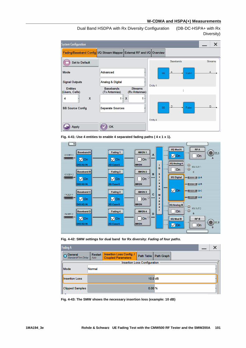
W-CDMA and HSPA(+) Measurements
Dual Band HSDPA with Rx Diversity Configuration (DB-DC-HSPA+ with Rx
Diversity)
1MA194_3e Rohde & Schwarz UE Fading Test with the CMW500 RF Tester and the SMW200A 101
Fig. 4-41: Use 4 entities to enable 4 separated fading paths ( 4 x 1 x 1).
Fig. 4-42: SMW settings for dual band for Rx diversity: Fading of four paths.
Fig. 4-43: The SMW shows the necessary insertion loss (example: 10 dB)

W-CDMA and HSPA(+) Measurements
CMW Internal Fading for W-CDMA and HSPA(+)
1MA194_3e Rohde & Schwarz UE Fading Test with the CMW500 RF Tester and the SMW200A 102
Remote command:
// set IQ in to PEP 0 dBFS and Level to -25.0 dBFS CONFigure:WCDMa:SIGN<i>:IQIN:CARRier<carrier> 0, -25.0
8. Use WCDMA Rx Meas to start the RX measurement (see section 4.1). Fig. 4-29
shows an example of a DC-HSPA measurement in the overview.
Fig. 4-44: WCDMA RX measurement for Dual-Band HSDPA. The measurements are adapted
automatically for both streams individually and for the overall assessment.
4.8 CMW Internal Fading for W-CDMA and HSPA(+)
For all of the above Fading scenarios (see also Table 4-1):
ı Standard cell fading
ı Standard cell Rx Diversity fading
ı Dual Carrier Fading
ı Dual Carrier Rx Diversity Fading

W-CDMA and HSPA(+) Measurements
CMW Internal Fading for W-CDMA and HSPA(+)
1MA194_3e Rohde & Schwarz UE Fading Test with the CMW500 RF Tester and the SMW200A 103
ı Dual Carrier / Dual Band Fading
ı Dual Carrier / Dual Band Rx Diversity Fading
the internal fading in the CMW can be used with the software option CMW-KE400. It
allows the predefined fading settings (3GPP TS 25.101, Annex B.2.):
ı Multi-path profiles
▪ Case 1 to 6
▪ ITU pedestrian A/B with 3 km/h (PA3, PB3)
▪ ITU vehicular A with 3 km/h, 30 km/h, 120 km/h (VA3, VA30, VA120)
ı Moving propagation
ı High speed train profile (HST)
ı Birth-death propagation
1. Set the wanted Scenario and set Fading to Internal.
Fig. 4-45: WCDMA scenario with internal fading
Remote commands:
// Standard Cell Fading internal
ROUTe:WCDMa:SIGN:SCENario:SCFading:INTernal RF1C,RX1,RF1C,TX1
// Rx Diversity Fading internal
ROUTe:WCDMa:SIGN:SCENario:SCFDiversity:INTernal
RF1C,RX1,RF1C,TX1,RF2C,TX2
// Dual Carrier Fading internal
ROUTe:WCDMa:SIGN:SCENario:DCFading:INTernal
RF1C,RX1,RF1C,TX1,RF3C,TX2
// Dual Carrier Diversity Fading internal
ROUTe:WCDMa:SIGN:SCENario:DCFDiversity:INTernal
RF1C,RX1,RF1C,TX1,RF2C,TX2
// Dual Band Fading internal
ROUTe:WCDMa:SIGN:SCENario:DBFading:INTernal
RF1C,RX1,RF1C,TX1,RF3C,TX2
// Dual Band Diversity Fading internal
ROUTe:WCDMa:SIGN:SCENario:DBFDiversity:INTernal
RF1C,RX1,RF1C,TX1,RF3C,TX2,
RF2C,TX3,RF4C,TX4,
2. Select under Fading Simulator the wanted Profile (example Case 1)
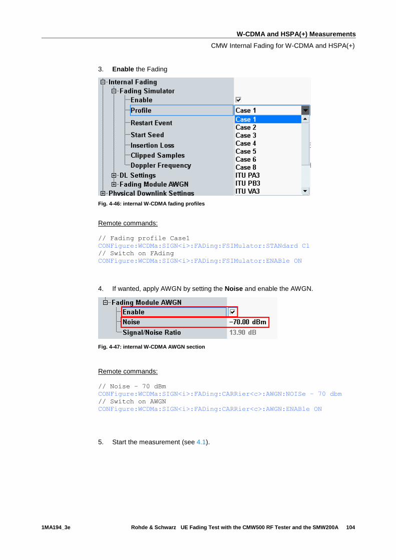
W-CDMA and HSPA(+) Measurements
CMW Internal Fading for W-CDMA and HSPA(+)
1MA194_3e Rohde & Schwarz UE Fading Test with the CMW500 RF Tester and the SMW200A 104
3. Enable the Fading
Fig. 4-46: internal W-CDMA fading profiles
Remote commands:
// Fading profile Case1
CONFigure:WCDMa:SIGN<i>:FADing:FSIMulator:STANdard C1
// Switch on FAding
CONFigure:WCDMa:SIGN<i>:FADing:FSIMulator:ENABle ON
4. If wanted, apply AWGN by setting the Noise and enable the AWGN.
Fig. 4-47: internal W-CDMA AWGN section
Remote commands:
// Noise – 70 dBm
CONFigure:WCDMa:SIGN<i>:FADing:CARRier<c>:AWGN:NOISe – 70 dbm
// Switch on AWGN
CONFigure:WCDMa:SIGN<i>:FADing:CARRier<c>:AWGN:ENABle ON
5. Start the measurement (see 4.1).
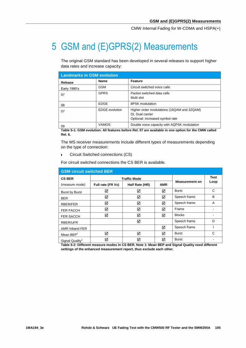
GSM and (E)GPRS(2) Measurements
CMW Internal Fading for W-CDMA and HSPA(+)
1MA194_3e Rohde & Schwarz UE Fading Test with the CMW500 RF Tester and the SMW200A 105
5 GSM and (E)GPRS(2) Measurements
The original GSM standard has been developed in several releases to support higher
data rates and increase capacity:
Landmarks in GSM evolution
Release Name Feature
Early 1990’s GSM Circuit switched voice calls
97 GPRS Packet switched data calls
Multi slot
98 EDGE 8PSK modulation
07 EDGE evolution Higher order modulations (16QAM and 32QAM)
DL Dual carrier
Optional: increased symbol rate
09 VAMOS Double voice capacity with AQPSK modulation
Table 5-1: GSM evolution: All features before Rel. 07 are available in one option for the CMW called
Rel. 6.
The MS receiver measurements include different types of measurements depending
on the type of connection:
ı Circuit Switched connections (CS)
For circuit switched connections the CS BER is available.
GSM circuit switched BER
CS BER
(measure mode)
Traffic Mode Measurement on
Test
Loop Full rate (FR Vx) Half Rate (HR) AMR
Burst by Burst Burst C
BER Speech frame B
RBER/FER Speech frame A
FER FACCH Frame -
FER SACCH Blocks -
RBER/UFR Speech frame D
AMR Inband FER Speech frame I
Mean BEP1 Burst C
Signal Quality1 Burst -
Table 5-2: Different measure modes in CS BER. Note 1: Mean BEP and Signal Quality need different
settings of the enhanced measurement report, thus exclude each other.
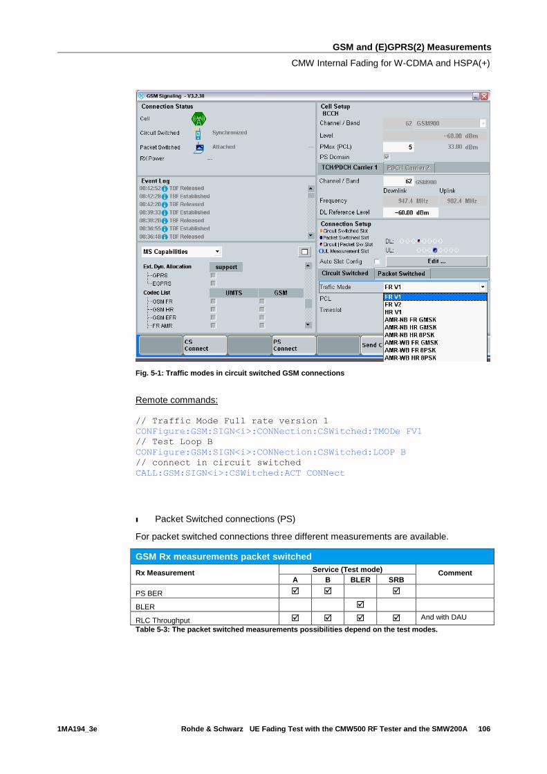
GSM and (E)GPRS(2) Measurements
CMW Internal Fading for W-CDMA and HSPA(+)
1MA194_3e Rohde & Schwarz UE Fading Test with the CMW500 RF Tester and the SMW200A 106
Fig. 5-1: Traffic modes in circuit switched GSM connections
Remote commands:
// Traffic Mode Full rate version 1 CONFigure:GSM:SIGN<i>:CONNection:CSWitched:TMODe FV1
// Test Loop B CONFigure:GSM:SIGN<i>:CONNection:CSWitched:LOOP B
// connect in circuit switched CALL:GSM:SIGN<i>:CSWitched:ACT CONNect
ı Packet Switched connections (PS)
For packet switched connections three different measurements are available.
GSM Rx measurements packet switched
Rx Measurement Service (Test mode) Comment A B BLER SRB
PS BER
BLER
RLC Throughput And with DAU
Table 5-3: The packet switched measurements possibilities depend on the test modes.

GSM and (E)GPRS(2) Measurements
CMW Internal Fading for W-CDMA and HSPA(+)
1MA194_3e Rohde & Schwarz UE Fading Test with the CMW500 RF Tester and the SMW200A 107
Fig. 5-2: Services in packet switched GSM connections
Remote commands:
// Service BLER CONFigure:GSM:SIGN<i>:CONNection:PSWitched:SERVice BLER
// connect in packet switched CALL:GSM:SIGN<i>:PSWitched:ACT CONNect
Auto Slot Configuration: Wizard
To simplify the multi slot settings, the CMW offers the Auto Slot Configuration
wizard. It reads the Multislot class information which the MS transmits during the
synchronization/attaching process to the CMW and sets the multi slot configuration
automatically according to the selected service.
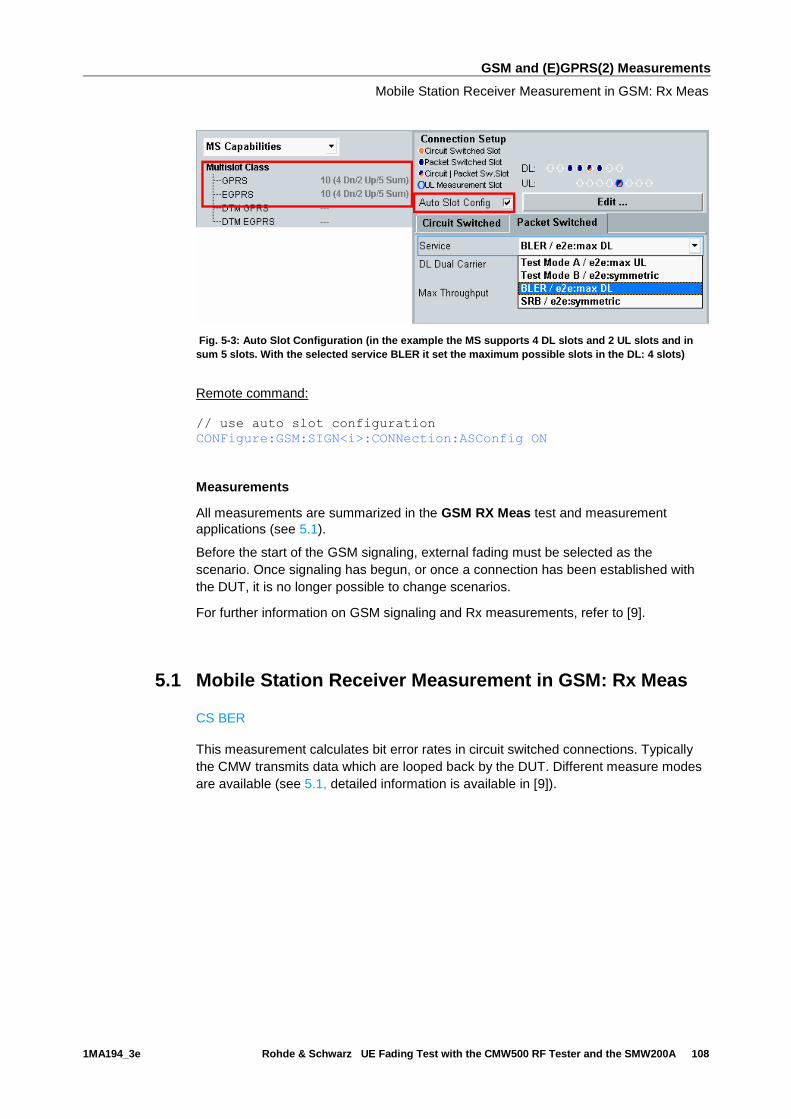
GSM and (E)GPRS(2) Measurements
Mobile Station Receiver Measurement in GSM: Rx Meas
1MA194_3e Rohde & Schwarz UE Fading Test with the CMW500 RF Tester and the SMW200A 108
Fig. 5-3: Auto Slot Configuration (in the example the MS supports 4 DL slots and 2 UL slots and in
sum 5 slots. With the selected service BLER it set the maximum possible slots in the DL: 4 slots)
Remote command:
// use auto slot configuration CONFigure:GSM:SIGN<i>:CONNection:ASConfig ON
Measurements
All measurements are summarized in the GSM RX Meas test and measurement
applications (see 5.1).
Before the start of the GSM signaling, external fading must be selected as the
scenario. Once signaling has begun, or once a connection has been established with
the DUT, it is no longer possible to change scenarios.
For further information on GSM signaling and Rx measurements, refer to [9].
5.1 Mobile Station Receiver Measurement in GSM: Rx Meas
CS BER
This measurement calculates bit error rates in circuit switched connections. Typically
the CMW transmits data which are looped back by the DUT. Different measure modes
are available (see 5.1, detailed information is available in [9]).
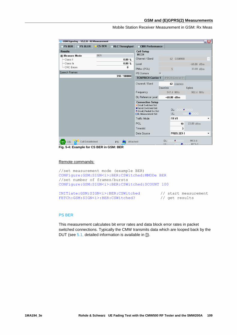
GSM and (E)GPRS(2) Measurements
Mobile Station Receiver Measurement in GSM: Rx Meas
1MA194_3e Rohde & Schwarz UE Fading Test with the CMW500 RF Tester and the SMW200A 109
Fig. 5-4: Example for CS BER in GSM: BER
Remote commands:
//set measurement mode (example BER)
CONFigure:GSM:SIGN<i>:BER:CSWitched:MMODe BER
//set number of frames/bursts
CONFigure:GSM:SIGN<i>:BER:CSWitched:SCOUNT 100
INITiate:GSM:SIGN<i>:BER:CSWitched // start measurement
FETCh:GSM:SIGN<i>:BER:CSWitched? // get results
PS BER
This measurement calculates bit error rates and data block error rates in packet
switched connections. Typically the CMW transmits data which are looped back by the
DUT (see 5.1, detailed information is available in []).
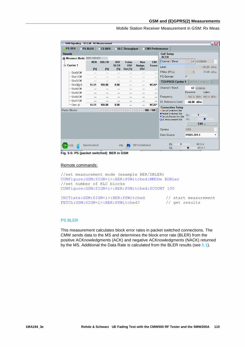
GSM and (E)GPRS(2) Measurements
Mobile Station Receiver Measurement in GSM: Rx Meas
1MA194_3e Rohde & Schwarz UE Fading Test with the CMW500 RF Tester and the SMW200A 110
Fig. 5-5: PS (packet switched) BER in GSM
Remote commands:
//set measurement mode (example BER/DBLER)
CONFigure:GSM:SIGN<i>:BER:PSWitched:MMODe BDBLer
//set number of RLC blocks
CONFigure:GSM:SIGN<i>:BER:PSWitched:SCOUNT 100
INITiate:GSM:SIGN<i>:BER:PSWitched // start measurement
FETCh:GSM:SIGN<i>:BER:PSWitched? // get results
PS BLER
This measurement calculates block error rates in packet switched connections. The
CMW sends data to the MS and determines the block error rate (BLER) from the
positive ACKnowledgments (ACK) and negative ACKnowledgments (NACK) returned
by the MS. Additional the Data Rate is calculated from the BLER results (see 5.1).
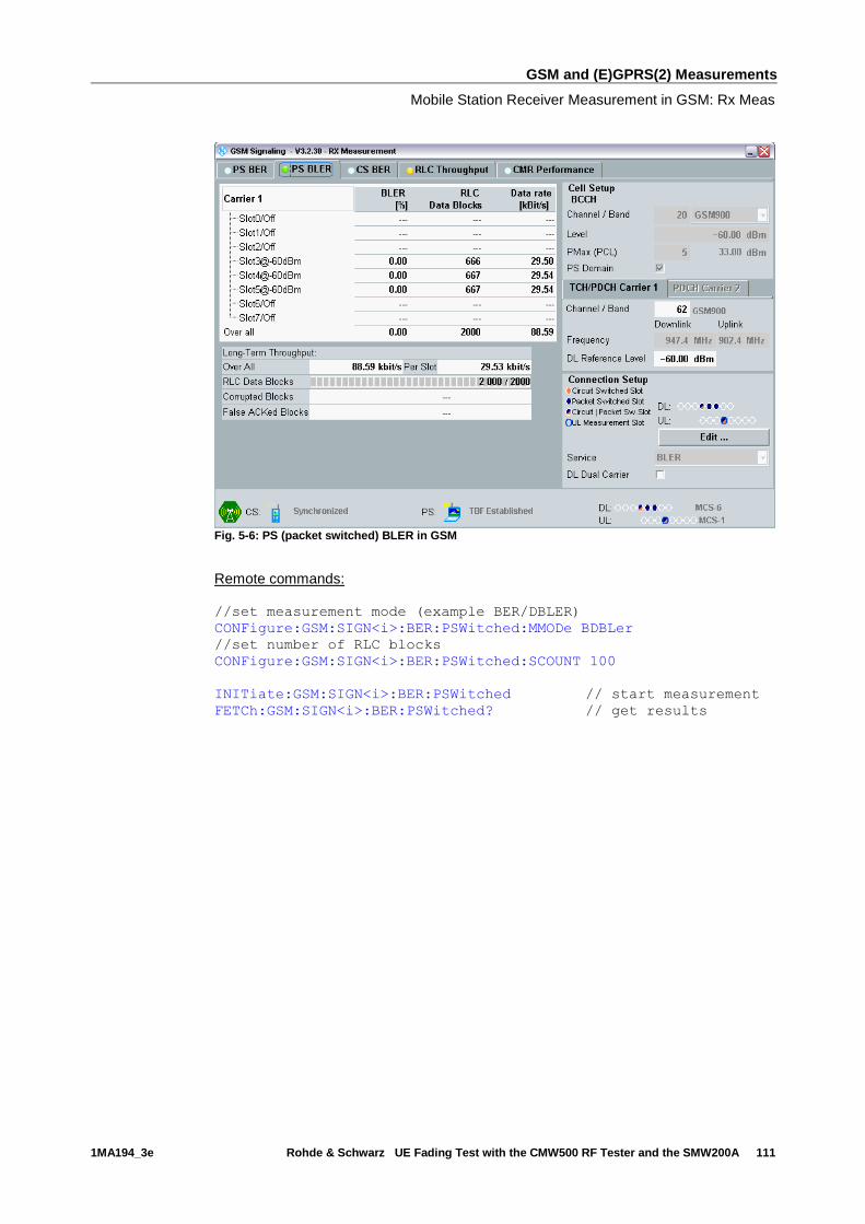
GSM and (E)GPRS(2) Measurements
Mobile Station Receiver Measurement in GSM: Rx Meas
1MA194_3e Rohde & Schwarz UE Fading Test with the CMW500 RF Tester and the SMW200A 111
Fig. 5-6: PS (packet switched) BLER in GSM
Remote commands:
//set measurement mode (example BER/DBLER)
CONFigure:GSM:SIGN<i>:BER:PSWitched:MMODe BDBLer
//set number of RLC blocks
CONFigure:GSM:SIGN<i>:BER:PSWitched:SCOUNT 100
INITiate:GSM:SIGN<i>:BER:PSWitched // start measurement
FETCh:GSM:SIGN<i>:BER:PSWitched? // get results
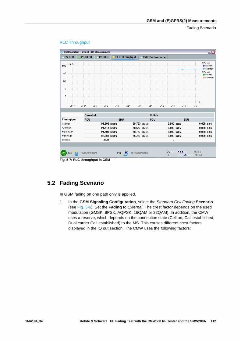
GSM and (E)GPRS(2) Measurements
Fading Scenario
1MA194_3e Rohde & Schwarz UE Fading Test with the CMW500 RF Tester and the SMW200A 112
RLC Throughput
Fig. 5-7: RLC throughput in GSM
5.2 Fading Scenario
In GSM fading on one path only is applied.
1. In the GSM Signaling Configuration, select the Standard Cell Fading Scenario
(see Fig. 3-6). Set the Fading to External. The crest factor depends on the used
modulation (GMSK, 8PSK, AQPSK, 16QAM or 32QAM). In addition, the CMW
uses a reserve, which depends on the connection state (Cell on, Call established,
Dual carrier Call established) to the MS. This causes different crest factors
displayed in the IQ out section. The CMW uses the following factors:

GSM and (E)GPRS(2) Measurements
Fading Scenario
1MA194_3e Rohde & Schwarz UE Fading Test with the CMW500 RF Tester and the SMW200A 113
GSM used crest factors
Coding schemes Modulation
Used crest factor
Call established Dual Carrier
Call established
Normal voice call
GPRS (CS 1…4)
EGPRS (MCS 1…4)
GMSK 6.00 dB 9.54 dB
EGPRS (MCS 5…9)
EGPRS2 (DAS 5…7) 8PSK 9.23 dB 12.77 dB
EGPRS2 (DAS 8…9) 16QAM 11.77 dB 15.31 dB
EGPRS2 (DAS 10…12) 32QAM 12.11 dB 15.65 dB
VAMOS AQPSK 9.39 dB 12.93 dB
Table 5-4: CMW Crest factors in GSM
Fig. 5-8: GSM scenario: Standard Cell Fading. The CMW indicates the crest factor, which is entered in
the SMW’s Dig IQ Input. As the crest factors depends on the used modulation and connection state,
different factors may appear.
Remote commands:
// Standard Cell Fading external via RF2COM and IQ2 Out
ROUTe:GSM:SIGN:SCENario:SCFading RF2C,RX1,RF2C,TX1,IQ2O
// read out information of IQ settings
SENSe:GSM:SIGN<i>:IQOut:PATH<n>?
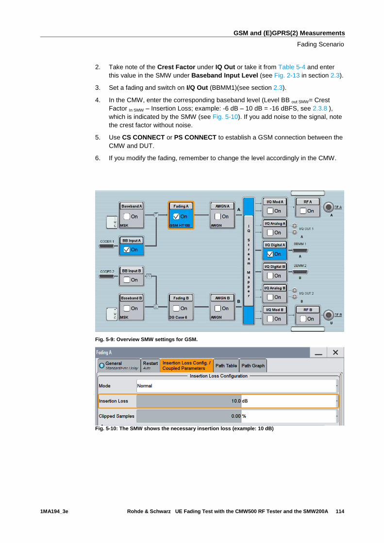
GSM and (E)GPRS(2) Measurements
Fading Scenario
1MA194_3e Rohde & Schwarz UE Fading Test with the CMW500 RF Tester and the SMW200A 114
2. Take note of the Crest Factor under IQ Out or take it from Table 5-4 and enter
this value in the SMW under Baseband Input Level (see Fig. 2-13 in section 2.3).
3. Set a fading and switch on I/Q Out (BBMM1)(see section 2.3).
4. In the CMW, enter the corresponding baseband level (Level BB out SMW= Crest
Factor In SMW – Insertion Loss; example: -6 dB – 10 dB = -16 dBFS, see 2.3.8 ),
which is indicated by the SMW (see Fig. 5-10). If you add noise to the signal, note
the crest factor without noise.
5. Use CS CONNECT or PS CONNECT to establish a GSM connection between the
CMW and DUT.
6. If you modify the fading, remember to change the level accordingly in the CMW.
Fig. 5-9: Overview SMW settings for GSM.
Fig. 5-10: The SMW shows the necessary insertion loss (example: 10 dB)

GSM and (E)GPRS(2) Measurements
Fading Scenario
1MA194_3e Rohde & Schwarz UE Fading Test with the CMW500 RF Tester and the SMW200A 115
Fig. 5-11: Making allowance for the necessary attenuation in the CMW. Here, the digital output level
of the SMW signal is entered as the IQ In level.
Remote command:
// set IQ In to PEP 0 dBFS and Level -16 dBFS
CONFigure:GSM:SIGN<i>:IQIN:PATH<n> 0.0, -16.0
7. Start the RX measurement using Rx MEAS (see section 5.1). Fig. 3-11 shows an
example.
Fig. 5-12: Example for a RX measurement in GSM: PS BLER on three downlink slots.

GSM and (E)GPRS(2) Measurements
Fading with Hopping (single DL carrier)
1MA194_3e Rohde & Schwarz UE Fading Test with the CMW500 RF Tester and the SMW200A 116
5.3 Fading with Hopping (single DL carrier)
The GSM standard also uses frequency hopping (FH) (3GPP TS 45.002). The CMW
together with the SMW allows tests under fading conditions in combination with
frequency hopping.
Fig. 5-13: Test setup GSM with hopping: the CMW provides the hopping trigger
To perform measurements with fading and hopping, use the same steps and settings
like in 5.2. In addition following steps are necessary:
1. Connect CMW output Trig A to SMW input USER 3.
2. Make sure that the Hopping Trigger is output at TRIG A (SETUP|Misc|Trigger).
Fig. 5-14: The CMW provides the hopping trigger at TRIG A.
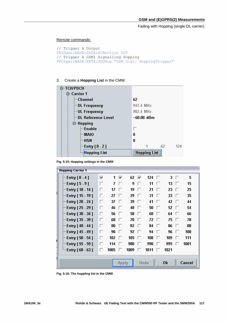
GSM and (E)GPRS(2) Measurements
Fading with Hopping (single DL carrier)
1MA194_3e Rohde & Schwarz UE Fading Test with the CMW500 RF Tester and the SMW200A 117
Remote commands:
// Trigger A Output
TRIGger:BASE:EXTA:DIRection OUT
// Trigger A GSM1 Signalling Hopping
TRIGger:BASE:EXTA:SOURce "GSM Sig1: HoppingTrigger"
3. Create a Hopping List in the CMW.
Fig. 5-15: Hopping settings in the CMW
Fig. 5-16: The hoppling list in the CMW
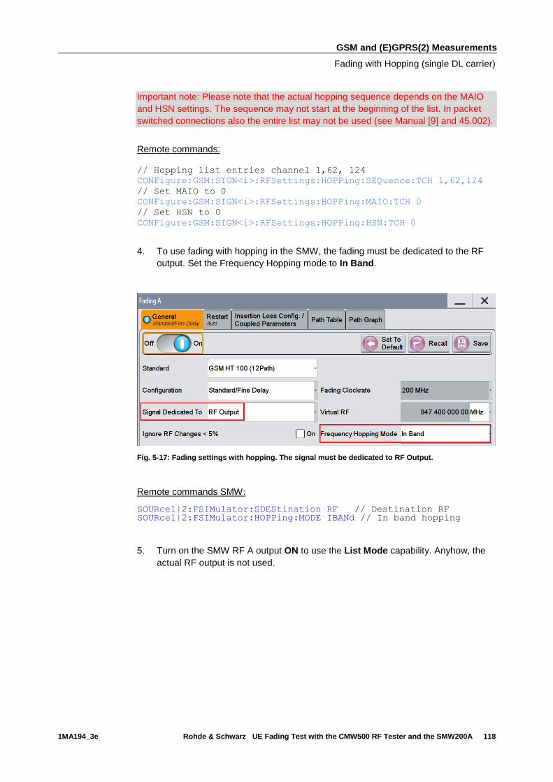
GSM and (E)GPRS(2) Measurements
Fading with Hopping (single DL carrier)
1MA194_3e Rohde & Schwarz UE Fading Test with the CMW500 RF Tester and the SMW200A 118
Important note: Please note that the actual hopping sequence depends on the MAIO
and HSN settings. The sequence may not start at the beginning of the list. In packet
switched connections also the entire list may not be used (see Manual [9] and 45.002).
Remote commands:
// Hopping list entries channel 1,62, 124
CONFigure:GSM:SIGN<i>:RFSettings:HOPPing:SEQuence:TCH 1,62,124
// Set MAIO to 0
CONFigure:GSM:SIGN<i>:RFSettings:HOPPing:MAIO:TCH 0
// Set HSN to 0
CONFigure:GSM:SIGN<i>:RFSettings:HOPPing:HSN:TCH 0
4. To use fading with hopping in the SMW, the fading must be dedicated to the RF
output. Set the Frequency Hopping mode to In Band.
Fig. 5-17: Fading settings with hopping. The signal must be dedicated to RF Output.
Remote commands SMW:
SOURce1|2:FSIMulator:SDEStination RF // Destination RF SOURce1|2:FSIMulator:HOPPing:MODE IBANd // In band hopping
5. Turn on the SMW RF A output ON to use the List Mode capability. Anyhow, the
actual RF output is not used.
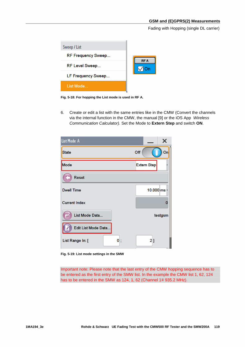
GSM and (E)GPRS(2) Measurements
Fading with Hopping (single DL carrier)
1MA194_3e Rohde & Schwarz UE Fading Test with the CMW500 RF Tester and the SMW200A 119
Fig. 5-18: For hopping the List mode is used in RF A.
6. Create or edit a list with the same entries like in the CMW (Convert the channels
via the internal function in the CMW, the manual [9] or the iOS App Wireless
Communication Calculator). Set the Mode to Extern Step and switch ON.
Fig. 5-19: List mode settings in the SMW
Important note: Please note that the last entry of the CMW hopping sequence has to
be entered as the first entry of the SMW list. In the example the CMW list 1, 62, 124
has to be entered in the SMW as 124, 1, 62 (Channel 1≡ 935.2 MHz).
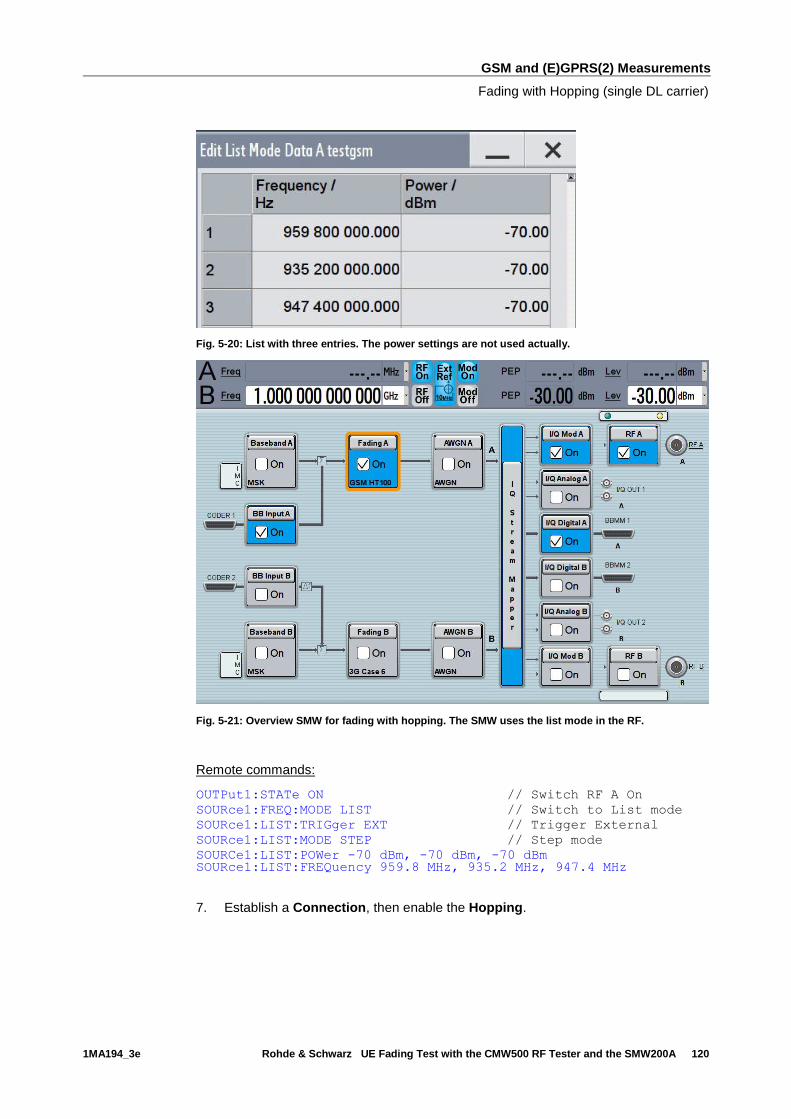
GSM and (E)GPRS(2) Measurements
Fading with Hopping (single DL carrier)
1MA194_3e Rohde & Schwarz UE Fading Test with the CMW500 RF Tester and the SMW200A 120
Fig. 5-20: List with three entries. The power settings are not used actually.
Fig. 5-21: Overview SMW for fading with hopping. The SMW uses the list mode in the RF.
Remote commands:
OUTPut1:STATe ON // Switch RF A On
SOURce1:FREQ:MODE LIST // Switch to List mode
SOURce1:LIST:TRIGger EXT // Trigger External
SOURce1:LIST:MODE STEP // Step mode
SOURCe1:LIST:POWer -70 dBm, -70 dBm, -70 dBm SOURce1:LIST:FREQuency 959.8 MHz, 935.2 MHz, 947.4 MHz
7. Establish a Connection, then enable the Hopping.
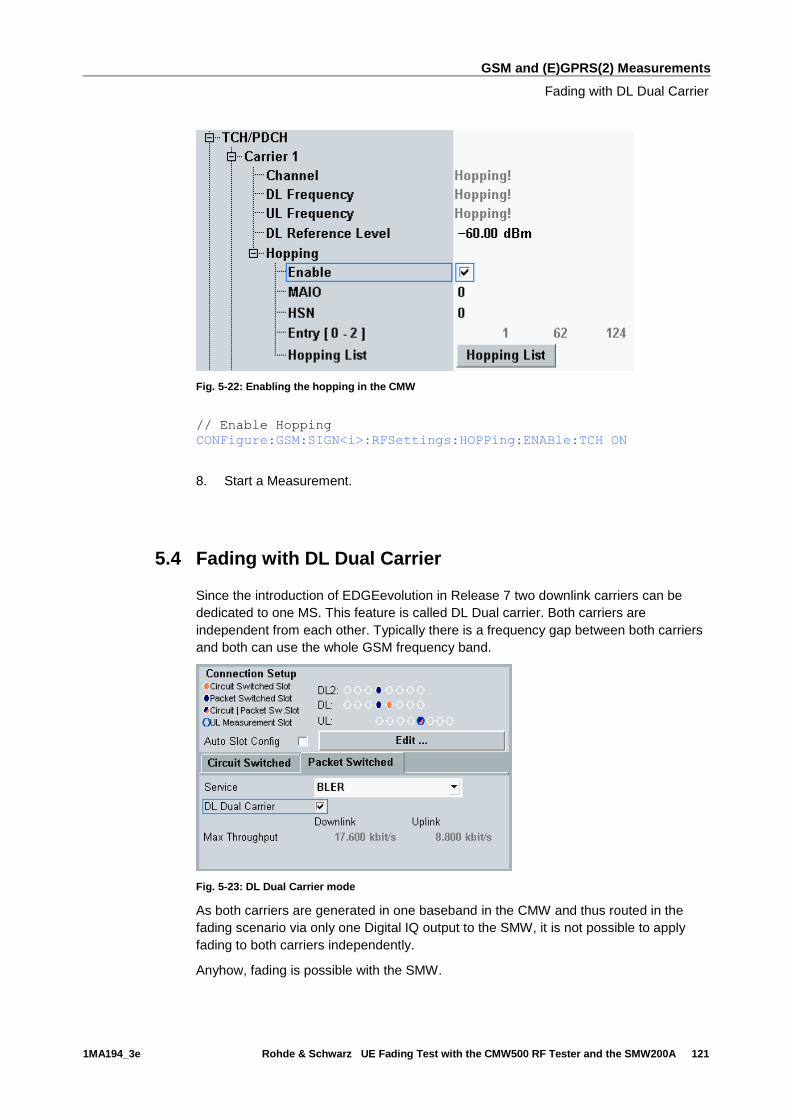
GSM and (E)GPRS(2) Measurements
Fading with DL Dual Carrier
1MA194_3e Rohde & Schwarz UE Fading Test with the CMW500 RF Tester and the SMW200A 121
Fig. 5-22: Enabling the hopping in the CMW
// Enable Hopping
CONFigure:GSM:SIGN<i>:RFSettings:HOPPing:ENABle:TCH ON
8. Start a Measurement.
5.4 Fading with DL Dual Carrier
Since the introduction of EDGEevolution in Release 7 two downlink carriers can be
dedicated to one MS. This feature is called DL Dual carrier. Both carriers are
independent from each other. Typically there is a frequency gap between both carriers
and both can use the whole GSM frequency band.
Fig. 5-23: DL Dual Carrier mode
As both carriers are generated in one baseband in the CMW and thus routed in the
fading scenario via only one Digital IQ output to the SMW, it is not possible to apply
fading to both carriers independently.
Anyhow, fading is possible with the SMW.
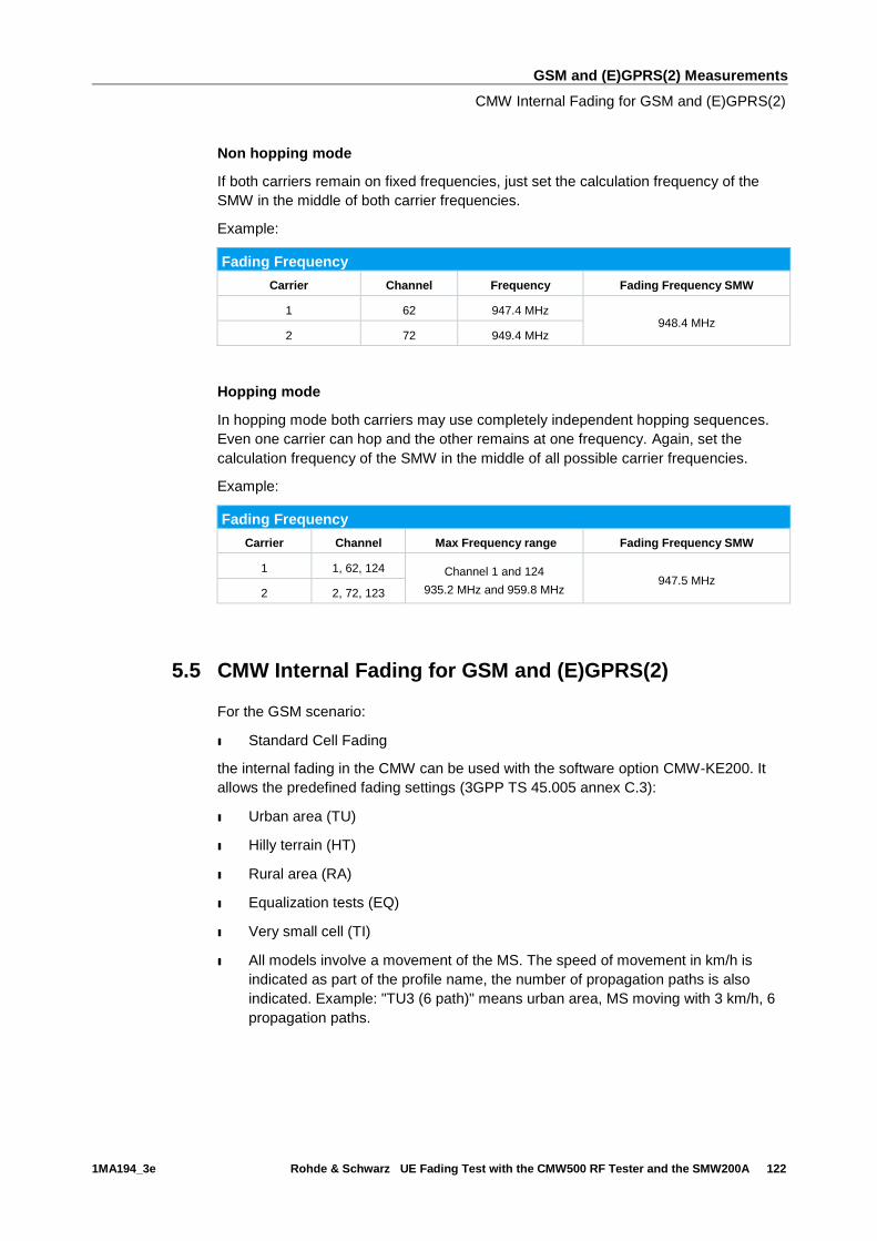
GSM and (E)GPRS(2) Measurements
CMW Internal Fading for GSM and (E)GPRS(2)
1MA194_3e Rohde & Schwarz UE Fading Test with the CMW500 RF Tester and the SMW200A 122
Non hopping mode
If both carriers remain on fixed frequencies, just set the calculation frequency of the
SMW in the middle of both carrier frequencies.
Example:
Fading Frequency
Carrier Channel Frequency Fading Frequency SMW
1 62 947.4 MHz 948.4 MHz
2 72 949.4 MHz
Hopping mode
In hopping mode both carriers may use completely independent hopping sequences.
Even one carrier can hop and the other remains at one frequency. Again, set the
calculation frequency of the SMW in the middle of all possible carrier frequencies.
Example:
Fading Frequency
Carrier Channel Max Frequency range Fading Frequency SMW
1 1, 62, 124 Channel 1 and 124
935.2 MHz and 959.8 MHz 947.5 MHz
2 2, 72, 123
5.5 CMW Internal Fading for GSM and (E)GPRS(2)
For the GSM scenario:
ı Standard Cell Fading
the internal fading in the CMW can be used with the software option CMW-KE200. It
allows the predefined fading settings (3GPP TS 45.005 annex C.3):
ı Urban area (TU)
ı Hilly terrain (HT)
ı Rural area (RA)
ı Equalization tests (EQ)
ı Very small cell (TI)
ı All models involve a movement of the MS. The speed of movement in km/h is
indicated as part of the profile name, the number of propagation paths is also
indicated. Example: "TU3 (6 path)" means urban area, MS moving with 3 km/h, 6
propagation paths.

GSM and (E)GPRS(2) Measurements
CMW Internal Fading for GSM and (E)GPRS(2)
1MA194_3e Rohde & Schwarz UE Fading Test with the CMW500 RF Tester and the SMW200A 123
1. Set the wanted Scenario and set Fading to Internal.
Fig. 5-24: GSM scenario with internal fading
Remote commands:
// Standard Cell Fading external via RF2COM
ROUTe:GSM:SIGN:SCENario:SCFading:INTernal RF2C,RX1,RF2C,TX1
2. Select under Fading Simulator the wanted Profile (example Case 1)
3. Enable the Fading
Fig. 5-25: internal GSM fading profiles
Remote commands:
// Fading profile TU3 6 paths
CONFigure:GSM:SIGN<i>:FADing:FSIMulator:STANdard T3P6
// Switch on FAding
CONFigure:GSM:SIGN<i>:FADing:FSIMulator:ENABle ON
4. If wanted, apply AWGN by setting the Signal/Noise and enable the AWGN.
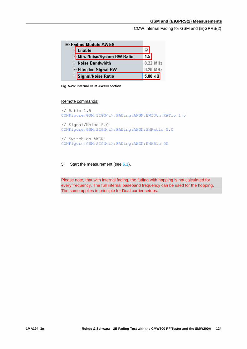
GSM and (E)GPRS(2) Measurements
CMW Internal Fading for GSM and (E)GPRS(2)
1MA194_3e Rohde & Schwarz UE Fading Test with the CMW500 RF Tester and the SMW200A 124
Fig. 5-26: internal GSM AWGN section
Remote commands:
// Ratio 1.5
CONFigure:GSM:SIGN<i>:FADing:AWGN:BWIDth:RATio 1.5
// Signal/Noise 5.0
CONFigure:GSM:SIGN<i>:FADing:AWGN:SNRatio 5.0
// Switch on AWGN
CONFigure:GSM:SIGN<i>:FADing:AWGN:ENABle ON
5. Start the measurement (see 5.1).
Please note, that with internal fading, the fading with hopping is not calculated for
every frequency. The full internal baseband frequency can be used for the hopping.
The same applies in principle for Dual carrier setups.
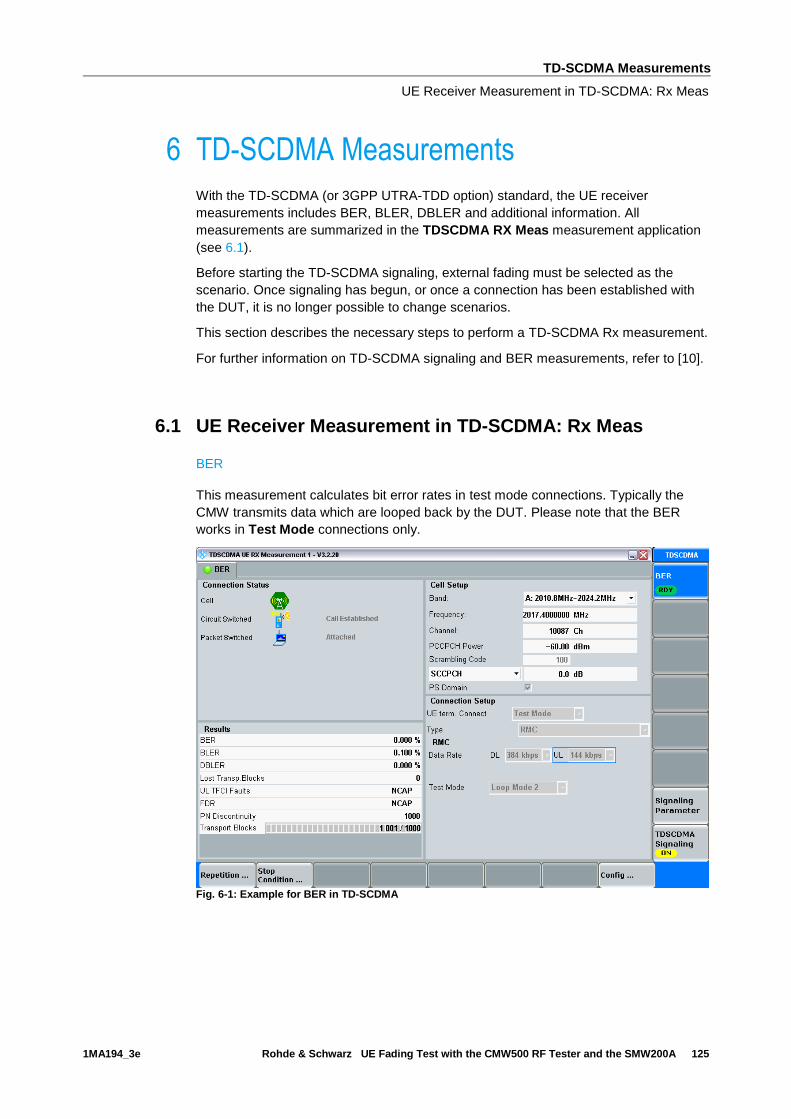
TD-SCDMA Measurements
UE Receiver Measurement in TD-SCDMA: Rx Meas
1MA194_3e Rohde & Schwarz UE Fading Test with the CMW500 RF Tester and the SMW200A 125
6 TD-SCDMA Measurements
With the TD-SCDMA (or 3GPP UTRA-TDD option) standard, the UE receiver
measurements includes BER, BLER, DBLER and additional information. All
measurements are summarized in the TDSCDMA RX Meas measurement application
(see 6.1).
Before starting the TD-SCDMA signaling, external fading must be selected as the
scenario. Once signaling has begun, or once a connection has been established with
the DUT, it is no longer possible to change scenarios.
This section describes the necessary steps to perform a TD-SCDMA Rx measurement.
For further information on TD-SCDMA signaling and BER measurements, refer to [10].
6.1 UE Receiver Measurement in TD-SCDMA: Rx Meas
BER
This measurement calculates bit error rates in test mode connections. Typically the
CMW transmits data which are looped back by the DUT. Please note that the BER
works in Test Mode connections only.
Fig. 6-1: Example for BER in TD-SCDMA
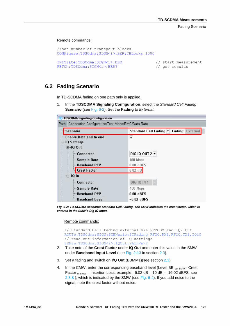
TD-SCDMA Measurements
Fading Scenario
1MA194_3e Rohde & Schwarz UE Fading Test with the CMW500 RF Tester and the SMW200A 126
Remote commands:
//set number of transport blocks
CONFigure:TDSCdma:SIGN<i>:BER:TBLocks 1000
INITiate:TDSCdma:SIGN<i>:BER // start measurement
FETCh:TDSCdma:SIGN<i>:BER? // get results
6.2 Fading Scenario
In TD-SCDMA fading on one path only is applied.
1. In the TDSCDMA Signaling Configuration, select the Standard Cell Fading
Scenario (see Fig. 6-2). Set the Fading to External.
Fig. 6-2: TD-SCDMA scenario: Standard Cell Fading. The CMW indicates the crest factor, which is
entered in the SMW’s Dig IQ Input.
Remote commands:
// Standard Cell Fading external via RF2COM and IQ2 Out
ROUTe:TDSCdma:SIGN:SCENario:SCFading RF2C,RX1,RF2C,TX1,IQ2O
// read out information of IQ settings
SENSe:TDSCdma:SIGN<i>:IQOut:PATH<n>?
2. Take note of the Crest Factor under IQ Out and enter this value in the SMW
under Baseband Input Level (see Fig. 2-13 in section 2.3).
3. Set a fading and switch on I/Q Out (BBMM1)(see section 2.3).
4. In the CMW, enter the corresponding baseband level (Level BB out SMW= Crest
Factor In SMW – Insertion Loss; example: -6.02 dB – 10 dB = -16.02 dBFS, see
2.3.8 ), which is indicated by the SMW (see Fig. 6-4). If you add noise to the
signal, note the crest factor without noise.
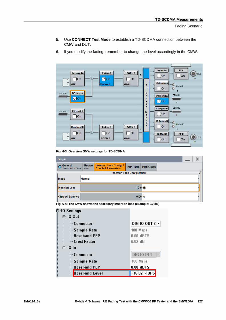
TD-SCDMA Measurements
Fading Scenario
1MA194_3e Rohde & Schwarz UE Fading Test with the CMW500 RF Tester and the SMW200A 127
5. Use CONNECT Test Mode to establish a TD-SCDMA connection between the
CMW and DUT.
6. If you modify the fading, remember to change the level accordingly in the CMW.
Fig. 6-3: Overview SMW settings for TD-SCDMA.
Fig. 6-4: The SMW shows the necessary insertion loss (example: 10 dB)
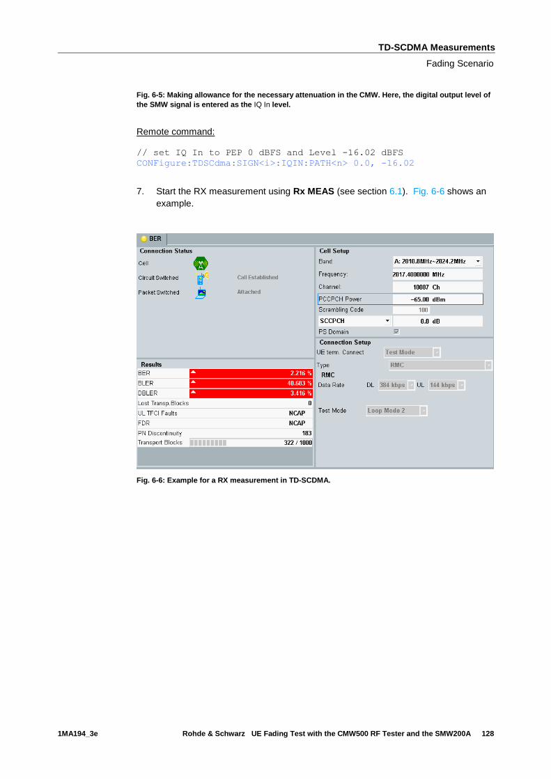
TD-SCDMA Measurements
Fading Scenario
1MA194_3e Rohde & Schwarz UE Fading Test with the CMW500 RF Tester and the SMW200A 128
Fig. 6-5: Making allowance for the necessary attenuation in the CMW. Here, the digital output level of
the SMW signal is entered as the IQ In level.
Remote command:
// set IQ In to PEP 0 dBFS and Level -16.02 dBFS
CONFigure:TDSCdma:SIGN<i>:IQIN:PATH<n> 0.0, -16.02
7. Start the RX measurement using Rx MEAS (see section 6.1). Fig. 6-6 shows an
example.
Fig. 6-6: Example for a RX measurement in TD-SCDMA.
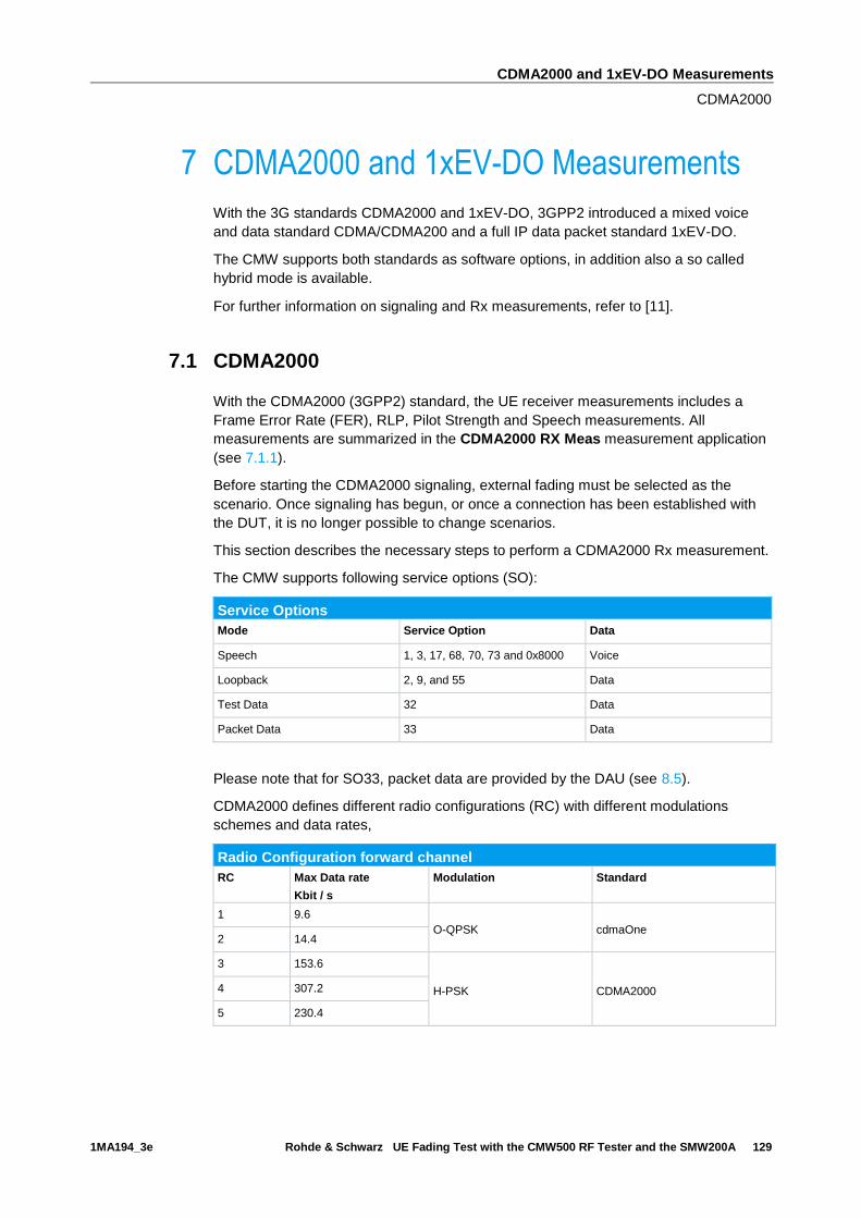
CDMA2000 and 1xEV-DO Measurements
CDMA2000
1MA194_3e Rohde & Schwarz UE Fading Test with the CMW500 RF Tester and the SMW200A 129
7 CDMA2000 and 1xEV-DO Measurements
With the 3G standards CDMA2000 and 1xEV-DO, 3GPP2 introduced a mixed voice
and data standard CDMA/CDMA200 and a full IP data packet standard 1xEV-DO.
The CMW supports both standards as software options, in addition also a so called
hybrid mode is available.
For further information on signaling and Rx measurements, refer to [11].
7.1 CDMA2000
With the CDMA2000 (3GPP2) standard, the UE receiver measurements includes a
Frame Error Rate (FER), RLP, Pilot Strength and Speech measurements. All
measurements are summarized in the CDMA2000 RX Meas measurement application
(see 7.1.1).
Before starting the CDMA2000 signaling, external fading must be selected as the
scenario. Once signaling has begun, or once a connection has been established with
the DUT, it is no longer possible to change scenarios.
This section describes the necessary steps to perform a CDMA2000 Rx measurement.
The CMW supports following service options (SO):
Service Options
Mode Service Option Data
Speech 1, 3, 17, 68, 70, 73 and 0x8000 Voice
Loopback 2, 9, and 55 Data
Test Data 32 Data
Packet Data 33 Data
Please note that for SO33, packet data are provided by the DAU (see 8.5).
CDMA2000 defines different radio configurations (RC) with different modulations
schemes and data rates,
Radio Configuration forward channel
RC Max Data rate
Kbit / s
Modulation Standard
1 9.6
O-QPSK cdmaOne 2 14.4
3 153.6
H-PSK CDMA2000 4 307.2
5 230.4

CDMA2000 and 1xEV-DO Measurements
CDMA2000
1MA194_3e Rohde & Schwarz UE Fading Test with the CMW500 RF Tester and the SMW200A 130
7.1.1 Mobile Station Receiver Measurement in CDMA2000: Rx Meas
Rx Meas in CDMA2000 provide different measurements, which also require different
service options (SO):
Service Options
Mode Service Option Data
Speech 1, 3, 17, 68, 70, 73 and 0x8000 Voice
Loopback 2, 9, and 55 Data
Test Data 32 Data
Packet Data 33 Data
Measurements
Rx Measurement 1, 3, 17, 68, 70, 73, 0x8000
Speech
2, 9, 55
Loopback
32
Test Data
33
Packet Data
FER FCH and FER SCH0
RLP
Pilot Power
Speech
FER FCH and FER SCH0
Here the Frame Error Rate of the Fundamental Channel (FCH) and the Supplemental
Channel 0 (SCH0) are determined. Views of both channels are analogical.
Fig. 7-1: Frame Error Rate measurement in CDMA200

CDMA2000 and 1xEV-DO Measurements
CDMA2000
1MA194_3e Rohde & Schwarz UE Fading Test with the CMW500 RF Tester and the SMW200A 131
Remote commands:
INITiate:CDMA:SIGN<i>:RXQuality:TDATa:FERFch // start
measurement
FETCh:CDMA:SIGN<i>:RXQuality:FERFch? // get results
RLP
This tab shows the RLP and IP statistics. This measurement requires an end-to-end
data connection with the DAU and SO33.
Fig. 7-2: RLP and IP statistics
Pilot Strength
The MS reports the total received power and the F-PICH power.
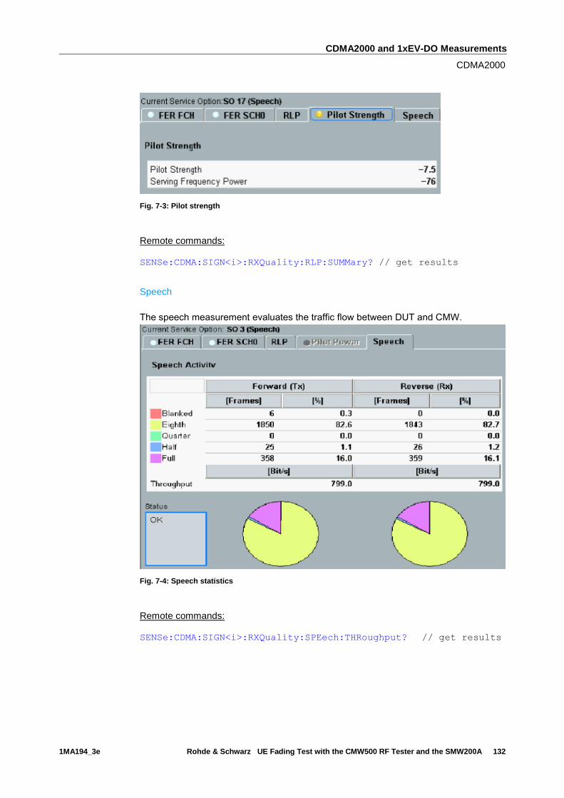
CDMA2000 and 1xEV-DO Measurements
CDMA2000
1MA194_3e Rohde & Schwarz UE Fading Test with the CMW500 RF Tester and the SMW200A 132
Fig. 7-3: Pilot strength
Remote commands:
SENSe:CDMA:SIGN<i>:RXQuality:RLP:SUMMary? // get results
Speech
The speech measurement evaluates the traffic flow between DUT and CMW.
Fig. 7-4: Speech statistics
Remote commands:
SENSe:CDMA:SIGN<i>:RXQuality:SPEech:THRoughput? // get results

CDMA2000 and 1xEV-DO Measurements
CDMA2000
1MA194_3e Rohde & Schwarz UE Fading Test with the CMW500 RF Tester and the SMW200A 133
7.1.2 Fading Scenario
In CDMA2000 fading on one path only is applied.
1. In the CDMA2000 Signaling Configuration, select the Standard Cell Fading
Scenario (see Fig. 6-2). Set the Fading to External.
Fig. 7-5: CDMA2000 scenario: Standard Cell Fading. The CMW indicates the crest factor, which is
entered in the SMW’s Dig IQ Input.
Remote commands:
// Standard Cell Fading external via RF2COM and IQ2 Out
ROUTe:CDMA:SIGN:SCENario:SCFading RF2C,RX1,RF2C,TX1,IQ2O
// read out information of IQ settings
SENSe:CDMA:SIGN<i>:IQOut:PATH<n>?
2. Take note of the Crest Factor under IQ Out and enter this value in the SMW
under Baseband Input Level (see Fig. 2-13 in section 2.3).
3. Set a fading and switch on I/Q Out (BBMM1)(see section 2.3).
4. In the CMW, enter the corresponding baseband level (Level BB out SMW= Crest
Factor In SMW – Insertion Loss; example: -9.0 dB – 10 dB = -19.0 dBFS, see 2.3.8 ),
which is indicated by the SMW (see Fig. 7-7). If you add noise to the signal, note
the crest factor without noise.
5. Use CONNECT 1st
SO to establish a CDMA2000 connection between the CMW
and DUT.
6. If you modify the fading, remember to change the level accordingly in the CMW.
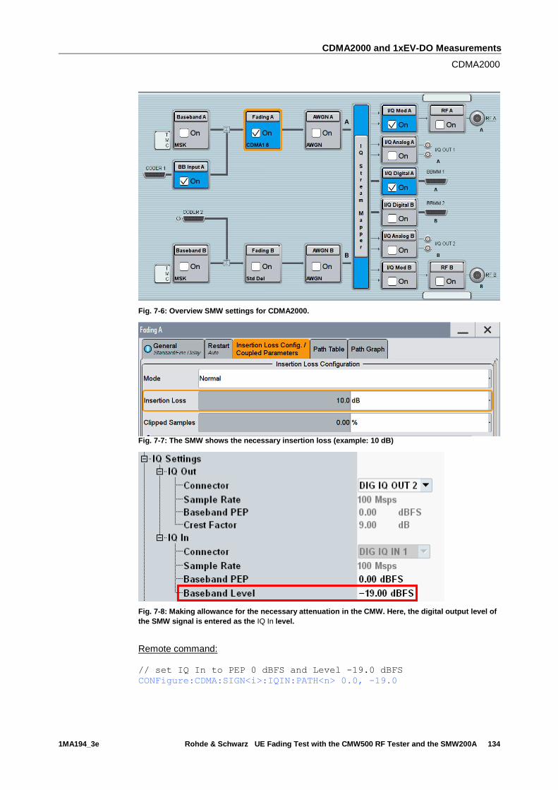
CDMA2000 and 1xEV-DO Measurements
CDMA2000
1MA194_3e Rohde & Schwarz UE Fading Test with the CMW500 RF Tester and the SMW200A 134
Fig. 7-6: Overview SMW settings for CDMA2000.
Fig. 7-7: The SMW shows the necessary insertion loss (example: 10 dB)
Fig. 7-8: Making allowance for the necessary attenuation in the CMW. Here, the digital output level of
the SMW signal is entered as the IQ In level.
Remote command:
// set IQ In to PEP 0 dBFS and Level -19.0 dBFS
CONFigure:CDMA:SIGN<i>:IQIN:PATH<n> 0.0, -19.0
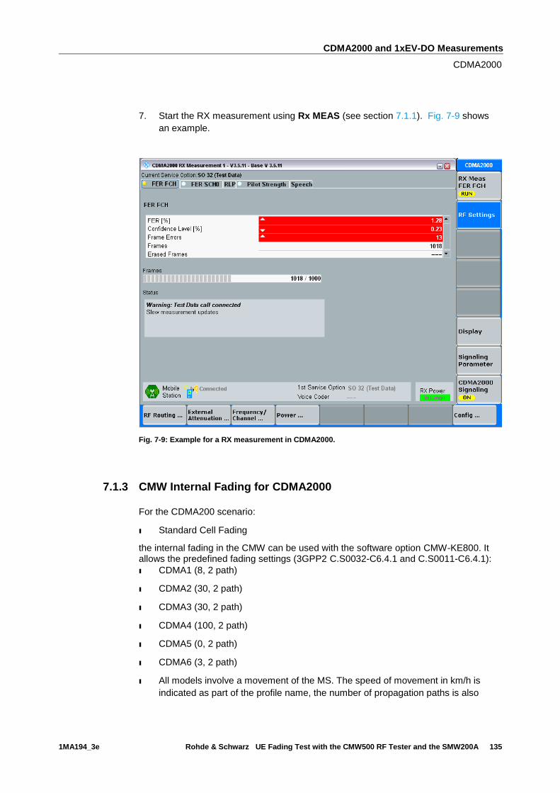
CDMA2000 and 1xEV-DO Measurements
CDMA2000
1MA194_3e Rohde & Schwarz UE Fading Test with the CMW500 RF Tester and the SMW200A 135
7. Start the RX measurement using Rx MEAS (see section 7.1.1). Fig. 7-9 shows
an example.
Fig. 7-9: Example for a RX measurement in CDMA2000.
7.1.3 CMW Internal Fading for CDMA2000
For the CDMA200 scenario:
ı Standard Cell Fading
the internal fading in the CMW can be used with the software option CMW-KE800. It allows the predefined fading settings (3GPP2 C.S0032-C6.4.1 and C.S0011-C6.4.1):
ı CDMA1 (8, 2 path)
ı CDMA2 (30, 2 path)
ı CDMA3 (30, 2 path)
ı CDMA4 (100, 2 path)
ı CDMA5 (0, 2 path)
ı CDMA6 (3, 2 path)
ı All models involve a movement of the MS. The speed of movement in km/h is
indicated as part of the profile name, the number of propagation paths is also
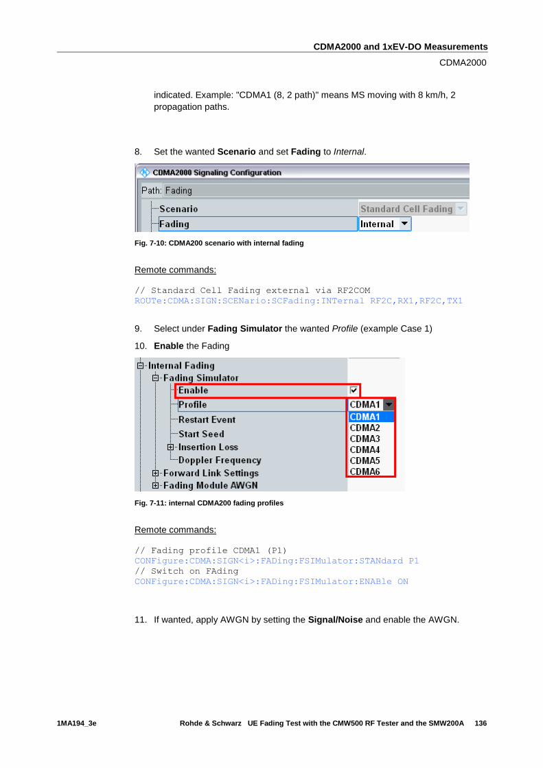
CDMA2000 and 1xEV-DO Measurements
CDMA2000
1MA194_3e Rohde & Schwarz UE Fading Test with the CMW500 RF Tester and the SMW200A 136
indicated. Example: "CDMA1 (8, 2 path)" means MS moving with 8 km/h, 2
propagation paths.
8. Set the wanted Scenario and set Fading to Internal.
Fig. 7-10: CDMA200 scenario with internal fading
Remote commands:
// Standard Cell Fading external via RF2COM
ROUTe:CDMA:SIGN:SCENario:SCFading:INTernal RF2C,RX1,RF2C,TX1
9. Select under Fading Simulator the wanted Profile (example Case 1)
10. Enable the Fading
Fig. 7-11: internal CDMA200 fading profiles
Remote commands:
// Fading profile CDMA1 (P1)
CONFigure:CDMA:SIGN<i>:FADing:FSIMulator:STANdard P1
// Switch on FAding
CONFigure:CDMA:SIGN<i>:FADing:FSIMulator:ENABle ON
11. If wanted, apply AWGN by setting the Signal/Noise and enable the AWGN.

CDMA2000 and 1xEV-DO Measurements
1xEV-DO
1MA194_3e Rohde & Schwarz UE Fading Test with the CMW500 RF Tester and the SMW200A 137
Fig. 7-12: internal CDMA2000 AWGN section
Remote commands:
// Ratio 1.5
CONFigure:CDMA:SIGN<i>:FADing:AWGN:BWIDth:RATio 1.5
// Signal/Noise 5.0
CONFigure:CDMA:SIGN<i>:FADing:AWGN:SNRatio 5.0
// Switch on AWGN
CONFigure:CDMA:SIGN<i>:FADing:AWGN:ENABle ON
12. Start the measurement (see 7.1.1).
7.2 1xEV-DO
With the 1xEV-DO (3GPP2) standard, the AT receiver measurements includes a
Frame Error Rate (FER), RLP, Pilot Strength and Speech measurements. All
measurements are summarized in the 1xEV-DO RX Meas measurement application
(see 7.2.1).
Before starting the 1xEV-DO signaling, external fading must be selected as the
scenario. Once signaling has begun, or once a connection has been established with
the DUT, it is no longer possible to change scenarios.
This section describes the necessary steps to perform a 1xEV-DO Rx measurement.
The CMW supports all revisions of the standard:
Revisions
Revision PHY subtype Max Data (Mbit/s)
Forward Link
Comments
Release 0 0 2.4
Revision A 1 and 2 3.1
Revision B 1, 2 and 3 4.9 per carrier CMW supports up to
3 carriers
1xEV-DO controls the data rate in the forward link by Data Rate Control (DRC). Please
see [12] for more information and [11] how to set up the data rate in the CMW.
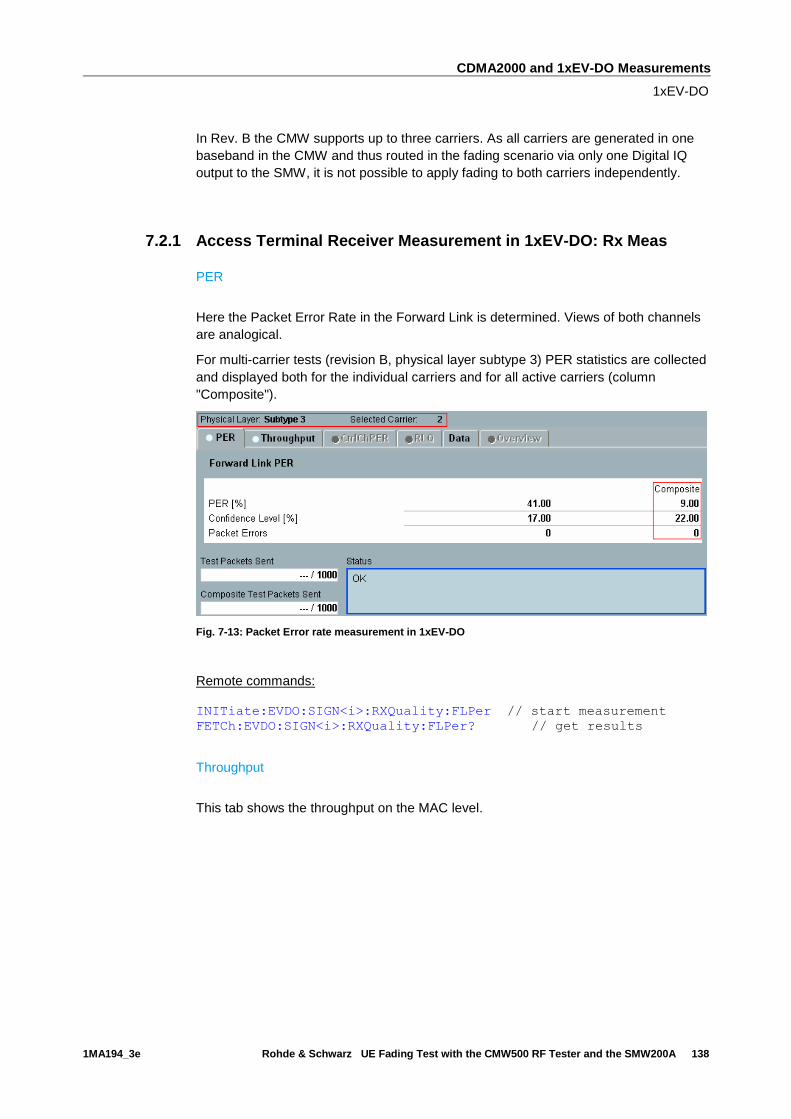
CDMA2000 and 1xEV-DO Measurements
1xEV-DO
1MA194_3e Rohde & Schwarz UE Fading Test with the CMW500 RF Tester and the SMW200A 138
In Rev. B the CMW supports up to three carriers. As all carriers are generated in one
baseband in the CMW and thus routed in the fading scenario via only one Digital IQ
output to the SMW, it is not possible to apply fading to both carriers independently.
7.2.1 Access Terminal Receiver Measurement in 1xEV-DO: Rx Meas
PER
Here the Packet Error Rate in the Forward Link is determined. Views of both channels
are analogical.
For multi-carrier tests (revision B, physical layer subtype 3) PER statistics are collected
and displayed both for the individual carriers and for all active carriers (column
"Composite").
Fig. 7-13: Packet Error rate measurement in 1xEV-DO
Remote commands:
INITiate:EVDO:SIGN<i>:RXQuality:FLPer // start measurement
FETCh:EVDO:SIGN<i>:RXQuality:FLPer? // get results
Throughput
This tab shows the throughput on the MAC level.
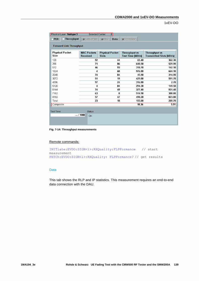
CDMA2000 and 1xEV-DO Measurements
1xEV-DO
1MA194_3e Rohde & Schwarz UE Fading Test with the CMW500 RF Tester and the SMW200A 139
Fig. 7-14: Throughput measurements
Remote commands:
INITiate:EVDO:SIGN<i>:RXQuality:FLPFormance // start
measurement
FETCh:EVDO:SIGN<i>:RXQuality: FLPFormance? // get results
Data
This tab shows the RLP and IP statistics. This measurement requires an end-to-end
data connection with the DAU.
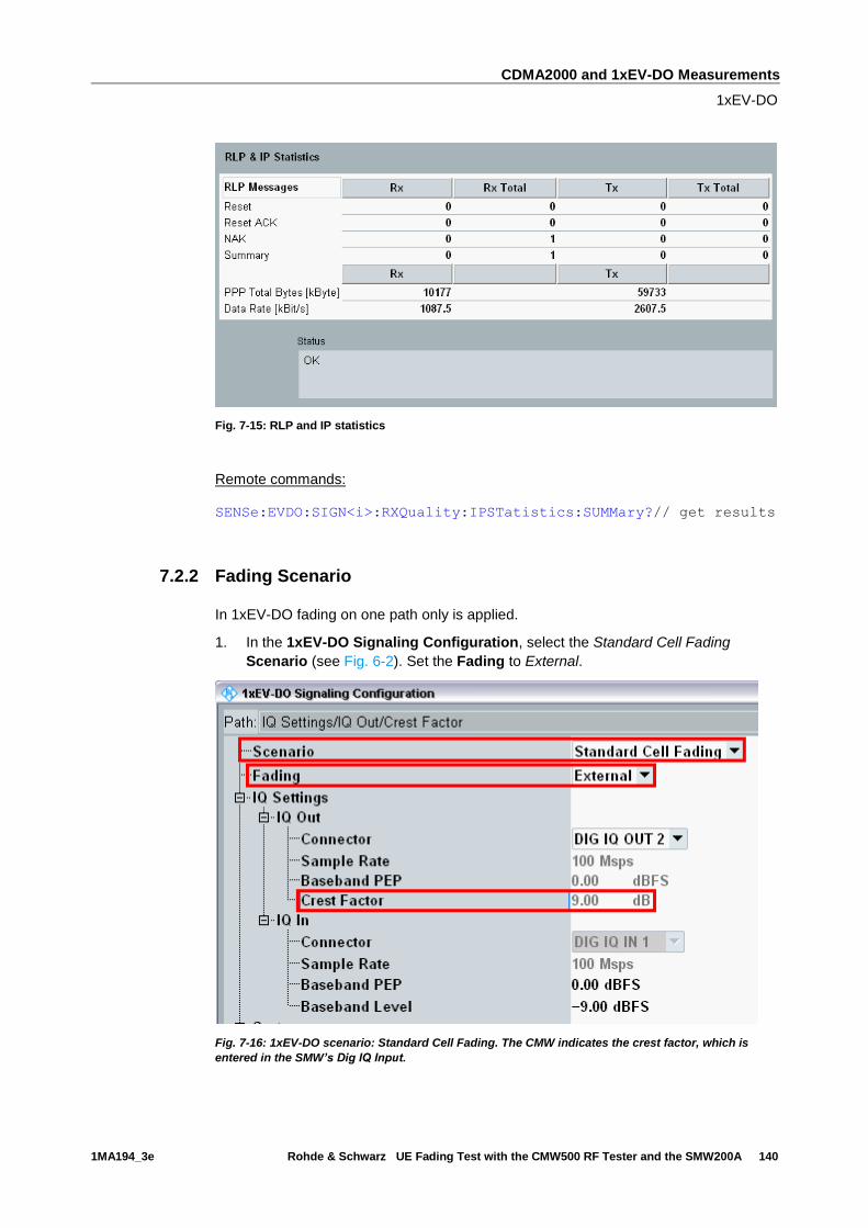
CDMA2000 and 1xEV-DO Measurements
1xEV-DO
1MA194_3e Rohde & Schwarz UE Fading Test with the CMW500 RF Tester and the SMW200A 140
Fig. 7-15: RLP and IP statistics
Remote commands:
SENSe:EVDO:SIGN<i>:RXQuality:IPSTatistics:SUMMary?// get results
7.2.2 Fading Scenario
In 1xEV-DO fading on one path only is applied.
1. In the 1xEV-DO Signaling Configuration, select the Standard Cell Fading
Scenario (see Fig. 6-2). Set the Fading to External.
Fig. 7-16: 1xEV-DO scenario: Standard Cell Fading. The CMW indicates the crest factor, which is
entered in the SMW’s Dig IQ Input.

CDMA2000 and 1xEV-DO Measurements
1xEV-DO
1MA194_3e Rohde & Schwarz UE Fading Test with the CMW500 RF Tester and the SMW200A 141
Remote commands:
// Standard Cell Fading external via RF2COM and IQ2 Out
ROUTe:EVDO:SIGN:SCENario:SCFading RF2C,RX1,RF2C,TX1,IQ2O
// read out information of IQ settings
SENSe:EVDO:SIGN<i>:IQOut:PATH<n>?
2. Take note of the Crest Factor under IQ Out and enter this value in the SMW
under Baseband Input Level (see Fig. 2-13 in section 2.3).
3. Set a fading and switch on I/Q Out (BBMM1)(see section 2.3).
4. In the CMW, enter the corresponding baseband level (Level BB out SMW= Crest
Factor In SMW – Insertion Loss; example: -9.0 dB – 10 dB = -19.0 dBFS, see 2.3.8 ),
which is indicated by the SMW (see Fig. 7-18). If you add noise to the signal, note
the crest factor without noise.
5. Use CONNECT to establish a 1xEV-DO connection between the CMW and DUT.
6. If you modify the fading, remember to change the level accordingly in the CMW.
Fig. 7-17: Overview SMW settings for 1xEV-DO.
Fig. 7-18: The SMW shows the necessary insertion loss (example: 10 dB)

CDMA2000 and 1xEV-DO Measurements
1xEV-DO
1MA194_3e Rohde & Schwarz UE Fading Test with the CMW500 RF Tester and the SMW200A 142
Fig. 7-19: Making allowance for the necessary attenuation in the CMW. Here, the digital output level
of the SMW signal is entered as the IQ In level.
Remote command:
// set IQ In to PEP 0 dBFS and Level -19.0 dBFS
CONFigure:EVDO:SIGN<i>:IQIN:PATH<n> 0.0, -19.0
7. Start the RX measurement using Rx MEAS (see section 7.2.1). Fig. 7-20 shows
an example.
Fig. 7-20: Example for a RX measurement in 1xEV-DO.

CDMA2000 and 1xEV-DO Measurements
1xEV-DO
1MA194_3e Rohde & Schwarz UE Fading Test with the CMW500 RF Tester and the SMW200A 143
7.2.3 CMW Internal Fading for 1xEV-DO
For the 1xEV-DO scenario:
ı Standard Cell Fading
the internal fading in the CMW can be used with the software option CMW-KE800. It allows the predefined fading settings (3GPP2 C.S0032):
ı EVDO1 (8, 2 path)
ı EVDO 2 (3, 1 path)
ı EVDO 3 (30, 1 path)
ı EVDO 4 (100, 3 path)
ı EVDO 5 (0, 2 path)
ı All models involve a movement of the AT. The speed of movement in km/h is
indicated as part of the profile name, the number of propagation paths is also
indicated. Example: " EVDO1 (8, 2 path)" means AT moving with 8 km/h, 2
propagation paths.
8. Set the wanted Scenario and set Fading to Internal.
Fig. 7-21: CDMA200 scenario with internal fading
Remote commands:
// Standard Cell Fading external via RF2COM
ROUTe:EVDO:SIGN:SCENario:SCFading:INTernal RF2C,RX1,RF2C,TX1
9. Select under Fading Simulator the wanted Profile (example Case 1)
10. Enable the Fading

CDMA2000 and 1xEV-DO Measurements
1xEV-DO
1MA194_3e Rohde & Schwarz UE Fading Test with the CMW500 RF Tester and the SMW200A 144
Fig. 7-22: internal 1xEV-DO fading profiles
Remote commands:
// Fading profile EVDO1 2 paths
CONFigure:EVDO:SIGN<i>:FADing:FSIMulator:STANdard P1
// Switch on FAding
CONFigure:EVDO:SIGN<i>:FADing:FSIMulator:ENABle ON
11. If wanted, apply AWGN by setting the Signal/Noise and enable the AWGN.
Fig. 7-23: internal 1xEV-DO AWGN section
Remote commands:
// Ratio 1.5
CONFigure:EVDO:SIGN<i>:FADing:AWGN:BWIDth:RATio 1.5
// Signal/Noise 5.0
CONFigure:EVDO:SIGN<i>:FADing:AWGN:SNRatio 5.0
// Switch on AWGN
CONFigure:EVDO:SIGN<i>:FADing:AWGN:ENABle ON
12. Start the measurement (see 7.2.1).
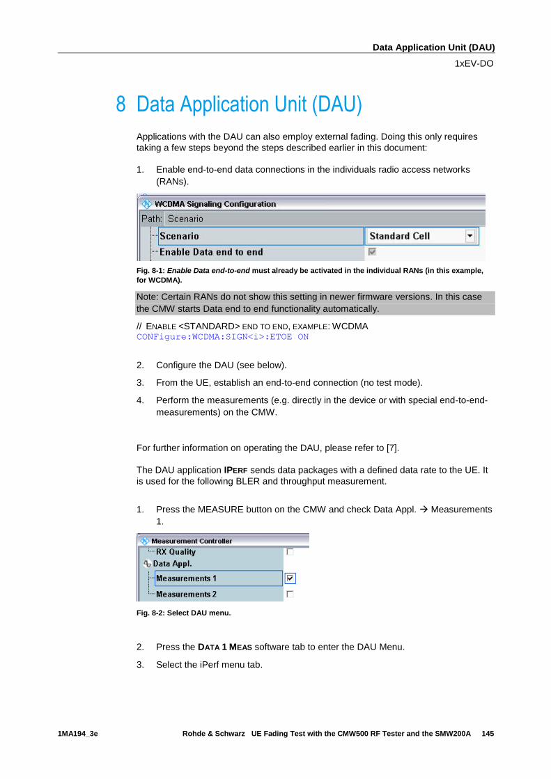
Data Application Unit (DAU)
1xEV-DO
1MA194_3e Rohde & Schwarz UE Fading Test with the CMW500 RF Tester and the SMW200A 145
8 Data Application Unit (DAU)
Applications with the DAU can also employ external fading. Doing this only requires
taking a few steps beyond the steps described earlier in this document:
1. Enable end-to-end data connections in the individuals radio access networks
(RANs).
Fig. 8-1: Enable Data end-to-end must already be activated in the individual RANs (in this example,
for WCDMA).
Note: Certain RANs do not show this setting in newer firmware versions. In this case
the CMW starts Data end to end functionality automatically.
// ENABLE <STANDARD> END TO END, EXAMPLE: WCDMA CONFigure:WCDMA:SIGN<i>:ETOE ON
2. Configure the DAU (see below).
3. From the UE, establish an end-to-end connection (no test mode).
4. Perform the measurements (e.g. directly in the device or with special end-to-end-
measurements) on the CMW.
For further information on operating the DAU, please refer to [7].
The DAU application IPERF sends data packages with a defined data rate to the UE. It
is used for the following BLER and throughput measurement.
1. Press the MEASURE button on the CMW and check Data Appl. Measurements
1.
Fig. 8-2: Select DAU menu.
2. Press the DATA 1 MEAS software tab to enter the DAU Menu.
3. Select the iPerf menu tab.
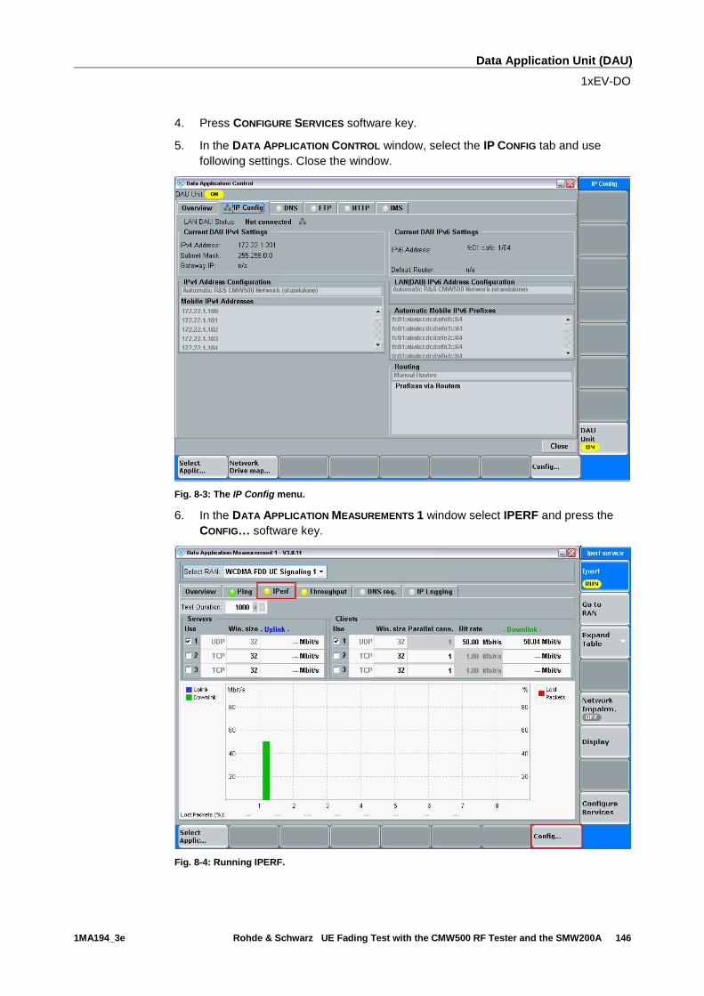
Data Application Unit (DAU)
1xEV-DO
1MA194_3e Rohde & Schwarz UE Fading Test with the CMW500 RF Tester and the SMW200A 146
4. Press CONFIGURE SERVICES software key.
5. In the DATA APPLICATION CONTROL window, select the IP CONFIG tab and use
following settings. Close the window.
Fig. 8-3: The IP Config menu.
6. In the DATA APPLICATION MEASUREMENTS 1 window select IPERF and press the
CONFIG… software key.
Fig. 8-4: Running IPERF.

Data Application Unit (DAU)
1xEV-DO
1MA194_3e Rohde & Schwarz UE Fading Test with the CMW500 RF Tester and the SMW200A 147
7. In the IPERF CONFIG window, select CLIENT #1, UDP and BIT RATE = e.g. 50 Mbit/s
(must be ≤ DL IP data rate). This sets the Downlink data rate. Press Ok to return
to the DATA APPLICATION MEASUREMENTS 1 window.
Fig. 8-5: IPerf Config window.
8. Press the Iperf software key and press the ON/OFF button. The yellow RUN
status message indicates that the data generator is running.
Fig. 8-6: Iperf is running.
Remote commands: Configuration: TEST DURATION – Time the test should last (in seconds). CONFigure:DATA:MEAS1:IPERf:TDURation 1000
PORT NUMBER – Data Application Unit (LAN DAU) port number for the connection. CONFigure:DATA:MEAS1:IPERf:CLIent1:PORT 5001
WINDOW SIZE – Size of the Negative Acknowledgement (NACK) window (in kbyte). CONFigure:DATA:MEAS1:IPERf:CLIent1:WSIZe 32
LISTEN PORT – UE's listen port number for the connection. CONFigure:DATA:MEAS1:IPERf:CLIent1:LPORt
BITRATE – Maximum bit rate to be transferred (in kbps). CONFigure:DATA:MEAS1:IPERf:CLIent1:BITRate 56M
PROTOCOL – Specifies the protocol used for data transfer for the client connection. CONFigure:DATA:MEAS1:IPERf:CLIent1:PROTocol UDP
IPADDRESS – Specifies the IP address of an IPerf client.
CONFigure:DATA:MEAS1:IPERf:CLIent1:IPADdress 172.22.1.100
ENABLE – Activates an IPerf client instance. CONFigure:DATA:MEAS1:IPERf:CLIENT1:ENABLE ON
Start/Stop generating data:
INIT:DATA:MEAS1:IPERf
STOP:DATA:MEAS1:IPERf
ABORt:DATA:MEAS1:IPERf

Data Application Unit (DAU)
LTE
1MA194_3e Rohde & Schwarz UE Fading Test with the CMW500 RF Tester and the SMW200A 148
9. Measure the throughput in the DAU application directly.
8.1 LTE
For LTE, there is one special setting for end-to-end tests.
Under Connection, the Type must be set to Data Application (Fig. 8-7).
Fig. 8-7: LTE special Settings for end-to-end tests: Data Application.
Remote command: // SET CONNECTION TYPE TO DATA APPLICATION CONFigure:LTE:SIGN<i>:CONNection:CTYPe DAPPlication
8.2 W-CDMA and with HSPA(+)
For W-CDMA, there are several special settings for end-to-end tests.
Under Packet Data, HSDPA or HSUPA should be entered under Data Rate (Fig. 8-8).
Here, too, the WCDMA Wizard is available for automatic setup using the UE capability
(see Fig. 4-1on page 77).

Data Application Unit (DAU)
W-CDMA and with HSPA(+)
1MA194_3e Rohde & Schwarz UE Fading Test with the CMW500 RF Tester and the SMW200A 149
Fig. 8-8: W-CDMA special settings for end-to-end tests: Packet data.
Remote command: // ENABLE WCDMA END TO END CONFigure:WCDMa:SIGN<i>:ETOE ON
// SET PACKET DATA DATA RATE TO HSDPA AND HSUPA CONFigure:WCDMa:SIGN<i>:CONNection:PACKet:DRATe HSDPa, HSUPa
The W-CDMA option offers an additional throughput measurement based on end-to-
end data connections (RLC throughput, see section 4.1). The HSDPA ACK and E-
HICH receiver measurements for Layer1 (under RX Meas, see section 4.1) also work
in the end-to-end configuration. Beyond this, all Tx tests can also be used with end-to-
end connections.
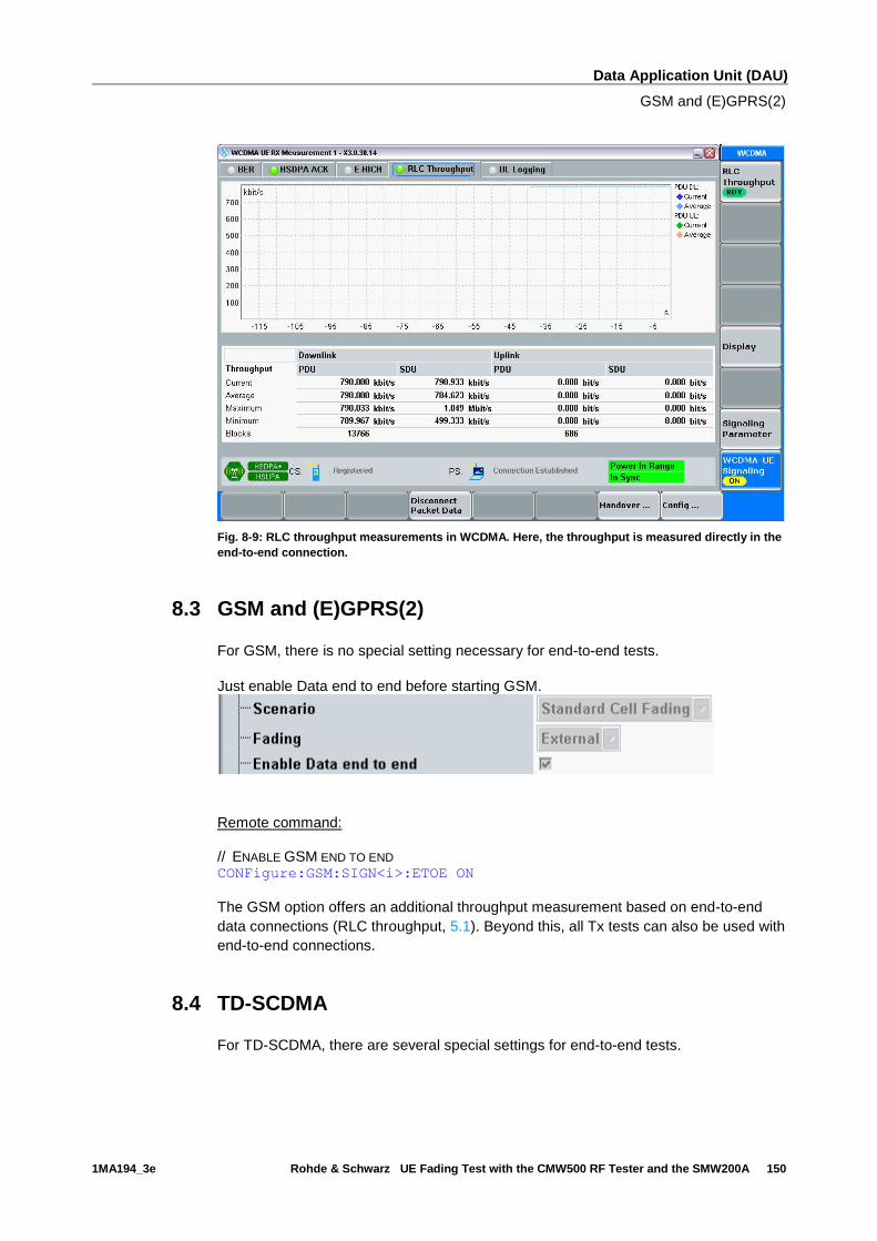
Data Application Unit (DAU)
GSM and (E)GPRS(2)
1MA194_3e Rohde & Schwarz UE Fading Test with the CMW500 RF Tester and the SMW200A 150
Fig. 8-9: RLC throughput measurements in WCDMA. Here, the throughput is measured directly in the
end-to-end connection.
8.3 GSM and (E)GPRS(2)
For GSM, there is no special setting necessary for end-to-end tests.
Just enable Data end to end before starting GSM.
Remote command: // ENABLE GSM END TO END CONFigure:GSM:SIGN<i>:ETOE ON
The GSM option offers an additional throughput measurement based on end-to-end
data connections (RLC throughput, 5.1). Beyond this, all Tx tests can also be used with
end-to-end connections.
8.4 TD-SCDMA
For TD-SCDMA, there are several special settings for end-to-end tests.

Data Application Unit (DAU)
CDMA2000 and 1XEV-DO
1MA194_3e Rohde & Schwarz UE Fading Test with the CMW500 RF Tester and the SMW200A 151
Under Packet Data, enter the wanted Data Rate ( Fig. 8-10). Make sure that the
Packet switched domain is enabled (Fig. 8-11).
Fig. 8-10: TD-SCDMA special settings for end-to-end tests: Packet data.
Fig. 8-11: PS domain
Remote command: // ENABLE TD-SCDMA END TO END CONFigure:TDSCdma:SIGN<i>:ETOE ON
// ENABLE PS DOMAIN CONFigure: TDSCdma:SIGN<i>:CELL:PSDomain ON
// SET PACKET DATA DATA RATE CONFigure: TDSCdma:SIGN<i>:CONNection:PACKet:DRATe R384,R128
Use the throughput measurement in the DAU (see 8). Beyond this, all Tx tests can also
be used with end-to-end connections.
8.5 CDMA2000 and 1XEV-DO
CDMA2000
For CDMA2000, there are several special settings for end-to-end tests.
First, the SO has to be SO33 (Packet Data). In Service Configuration, set Accept
Packet Calls to Accept as the AT sets up the connection (Fig. 8-12).

Data Application Unit (DAU)
CDMA2000 and 1XEV-DO
1MA194_3e Rohde & Schwarz UE Fading Test with the CMW500 RF Tester and the SMW200A 152
Fig. 8-12: CDMA2000 special settings for end-to-end tests.
Remote command: // SET SO 33 CONFigure:CDMA:SIGN<i>:PREConfiguration:LAYer:SOPTion:FIRSt SO33
// ACCEPT PACKET CALLS CONFigure:CDMA:SIGN<i>:SCONfig:APCalls ACCept
Use the throughput measurement in the DAU (see 8). Beyond this, all Tx tests can also
be used with end-to-end connections.
1xEV-DO
For 1xEV-DO, there is one special setting for end-to-end tests.
Set the Application to Packet (Fig. 8-13).
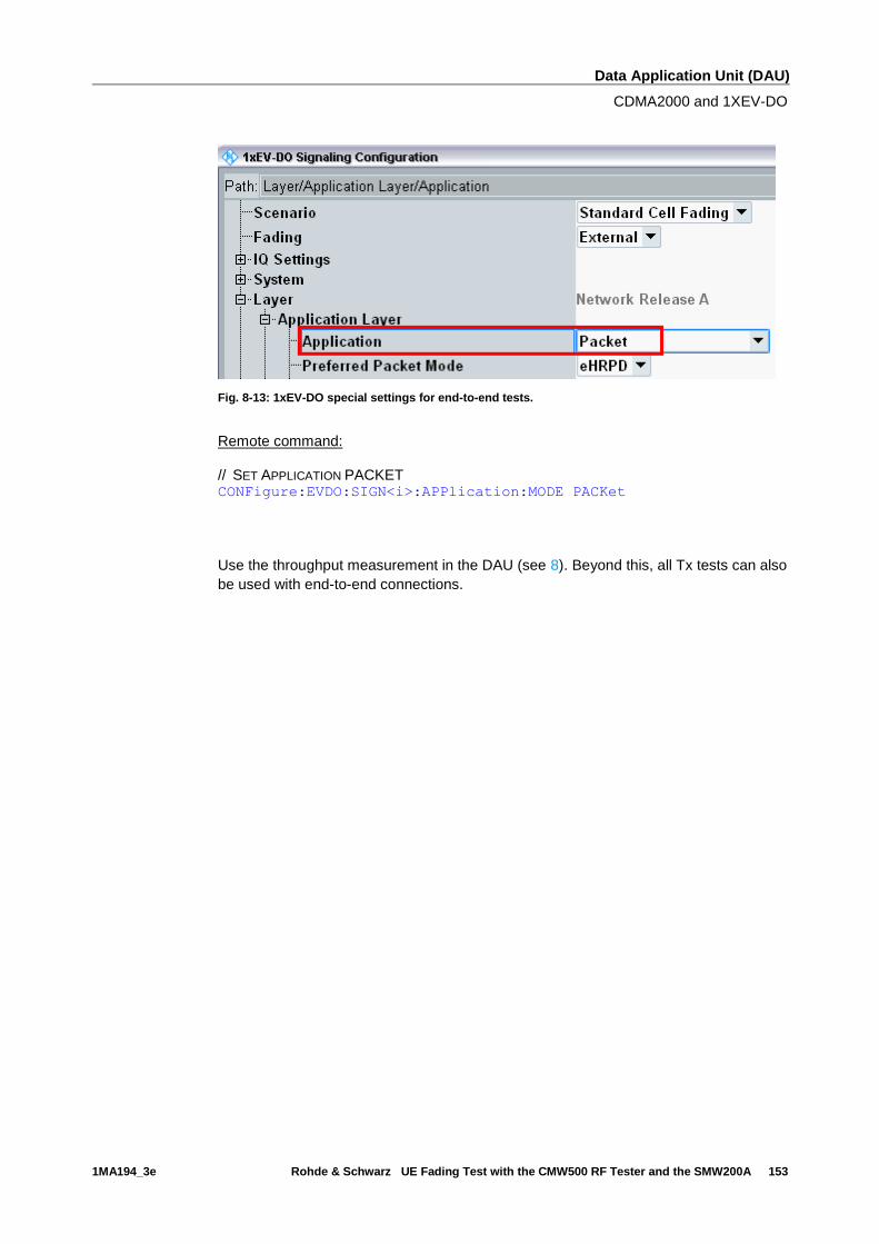
Data Application Unit (DAU)
CDMA2000 and 1XEV-DO
1MA194_3e Rohde & Schwarz UE Fading Test with the CMW500 RF Tester and the SMW200A 153
Fig. 8-13: 1xEV-DO special settings for end-to-end tests.
Remote command: // SET APPLICATION PACKET CONFigure:EVDO:SIGN<i>:APPlication:MODE PACKet
Use the throughput measurement in the DAU (see 8). Beyond this, all Tx tests can also
be used with end-to-end connections.
Appendix
Literature
1MA194_3e Rohde & Schwarz UE Fading Test with the CMW500 RF Tester and the SMW200A 154
9 Appendix
9.1 Literature
[1] Application Note 1MA111, UMTS Long Term Evolution (LTE) Technology
Introduction
[2] Application Note 1MA142, Introduction to MIMO
[3] Application Note 1GP51 Guidelines for MIMO Test Setups – Part 2
[4] Application Note 1SP11 WiMAX MIMO Multipath Performance Measurements
[5] User Manual, R&S®CMW-KM5xx/-KS5xx LTE Firmware Applications
[6] User Manual, R&S®CMW-KG4xx/-KM4xx/-KS4xx WCDMA Firmware Applications
[7] User Manual, R&S®CMW-B450A/-KM050 Data Application Units
[8] Application Note 1MA177 LTE Terminal Tests under Fading Conditions with
R&S®CMW500 and R&S®AMU200A
[9] User Manual, R&S®CMW-KM2xx/-KS2xx GSM Firmware Applications
[10] User Manual, R&S®CMW-KM75x/-KS750/KS760 TD-SCDMA Firmware
Applications
[11] User Manual, R&S®CMW-KM8xx/-KS8xx CDMA2000 1xRTT and 1xEV-DO
Firmware Applications
[12] White Paper 1MA213 1xEV-DO Revision A + B
9.2 Additional Information
Please send your comments and suggestions regarding this application note to
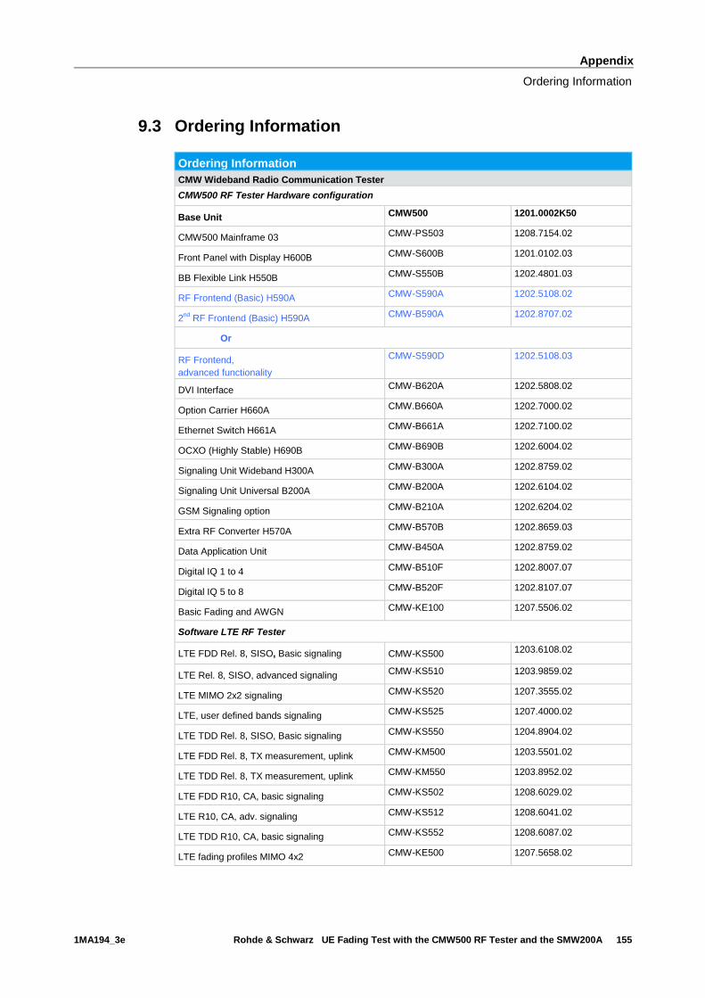
Appendix
Ordering Information
1MA194_3e Rohde & Schwarz UE Fading Test with the CMW500 RF Tester and the SMW200A 155
9.3 Ordering Information
Ordering Information
CMW Wideband Radio Communication Tester
CMW500 RF Tester Hardware configuration
Base Unit CMW500 1201.0002K50
CMW500 Mainframe 03 CMW-PS503 1208.7154.02
Front Panel with Display H600B CMW-S600B 1201.0102.03
BB Flexible Link H550B CMW-S550B 1202.4801.03
RF Frontend (Basic) H590A CMW-S590A 1202.5108.02
2nd
RF Frontend (Basic) H590A CMW-B590A 1202.8707.02
Or
RF Frontend,
advanced functionality
CMW-S590D 1202.5108.03
DVI Interface CMW-B620A 1202.5808.02
Option Carrier H660A CMW.B660A 1202.7000.02
Ethernet Switch H661A CMW-B661A 1202.7100.02
OCXO (Highly Stable) H690B CMW-B690B 1202.6004.02
Signaling Unit Wideband H300A CMW-B300A 1202.8759.02
Signaling Unit Universal B200A CMW-B200A 1202.6104.02
GSM Signaling option CMW-B210A 1202.6204.02
Extra RF Converter H570A CMW-B570B 1202.8659.03
Data Application Unit CMW-B450A 1202.8759.02
Digital IQ 1 to 4 CMW-B510F 1202.8007.07
Digital IQ 5 to 8 CMW-B520F 1202.8107.07
Basic Fading and AWGN CMW-KE100 1207.5506.02
Software LTE RF Tester
LTE FDD Rel. 8, SISO, Basic signaling CMW-KS500 1203.6108.02
LTE Rel. 8, SISO, advanced signaling CMW-KS510 1203.9859.02
LTE MIMO 2x2 signaling CMW-KS520 1207.3555.02
LTE, user defined bands signaling CMW-KS525 1207.4000.02
LTE TDD Rel. 8, SISO, Basic signaling CMW-KS550 1204.8904.02
LTE FDD Rel. 8, TX measurement, uplink CMW-KM500 1203.5501.02
LTE TDD Rel. 8, TX measurement, uplink CMW-KM550 1203.8952.02
LTE FDD R10, CA, basic signaling CMW-KS502 1208.6029.02
LTE R10, CA, adv. signaling CMW-KS512 1208.6041.02
LTE TDD R10, CA, basic signaling CMW-KS552 1208.6087.02
LTE fading profiles MIMO 4x2 CMW-KE500 1207.5658.02
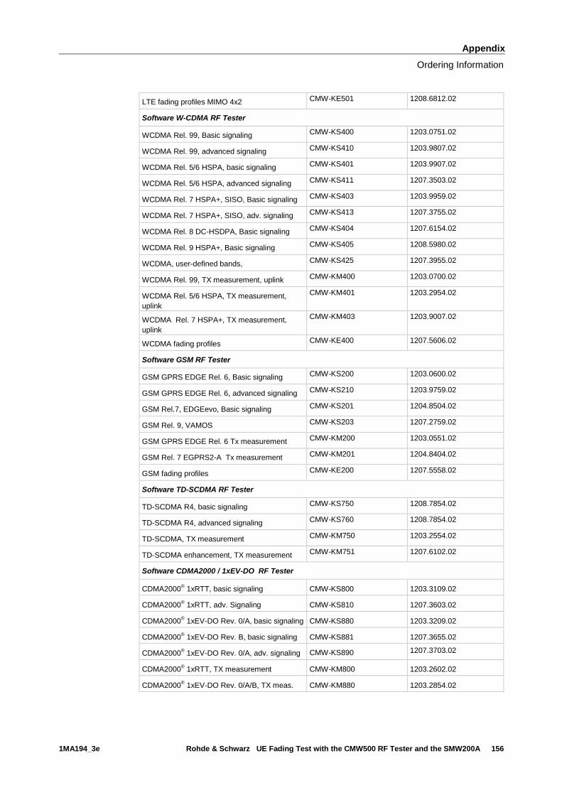
Appendix
Ordering Information
1MA194_3e Rohde & Schwarz UE Fading Test with the CMW500 RF Tester and the SMW200A 156
LTE fading profiles MIMO 4x2 CMW-KE501 1208.6812.02
Software W-CDMA RF Tester
WCDMA Rel. 99, Basic signaling CMW-KS400 1203.0751.02
WCDMA Rel. 99, advanced signaling CMW-KS410 1203.9807.02
WCDMA Rel. 5/6 HSPA, basic signaling CMW-KS401 1203.9907.02
WCDMA Rel. 5/6 HSPA, advanced signaling CMW-KS411 1207.3503.02
WCDMA Rel. 7 HSPA+, SISO, Basic signaling CMW-KS403 1203.9959.02
WCDMA Rel. 7 HSPA+, SISO, adv. signaling CMW-KS413 1207.3755.02
WCDMA Rel. 8 DC-HSDPA, Basic signaling CMW-KS404 1207.6154.02
WCDMA Rel. 9 HSPA+, Basic signaling CMW-KS405 1208.5980.02
WCDMA, user-defined bands, CMW-KS425 1207.3955.02
WCDMA Rel. 99, TX measurement, uplink CMW-KM400 1203.0700.02
WCDMA Rel. 5/6 HSPA, TX measurement,
uplink
CMW-KM401 1203.2954.02
WCDMA Rel. 7 HSPA+, TX measurement,
uplink
CMW-KM403 1203.9007.02
WCDMA fading profiles CMW-KE400 1207.5606.02
Software GSM RF Tester
GSM GPRS EDGE Rel. 6, Basic signaling CMW-KS200 1203.0600.02
GSM GPRS EDGE Rel. 6, advanced signaling CMW-KS210 1203.9759.02
GSM Rel.7, EDGEevo, Basic signaling CMW-KS201 1204.8504.02
GSM Rel. 9, VAMOS CMW-KS203 1207.2759.02
GSM GPRS EDGE Rel. 6 Tx measurement CMW-KM200 1203.0551.02
GSM Rel. 7 EGPRS2-A Tx measurement CMW-KM201 1204.8404.02
GSM fading profiles CMW-KE200 1207.5558.02
Software TD-SCDMA RF Tester
TD-SCDMA R4, basic signaling CMW-KS750 1208.7854.02
TD-SCDMA R4, advanced signaling CMW-KS760 1208.7854.02
TD-SCDMA, TX measurement CMW-KM750 1203.2554.02
TD-SCDMA enhancement, TX measurement CMW-KM751 1207.6102.02
Software CDMA2000 / 1xEV-DO RF Tester
CDMA2000® 1xRTT, basic signaling CMW-KS800 1203.3109.02
CDMA2000® 1xRTT, adv. Signaling CMW-KS810 1207.3603.02
CDMA2000® 1xEV-DO Rev. 0/A, basic signaling CMW-KS880 1203.3209.02
CDMA2000® 1xEV-DO Rev. B, basic signaling CMW-KS881 1207.3655.02
CDMA2000® 1xEV-DO Rev. 0/A, adv. signaling CMW-KS890 1207.3703.02
CDMA2000® 1xRTT, TX measurement CMW-KM800 1203.2602.02
CDMA2000® 1xEV-DO Rev. 0/A/B, TX meas. CMW-KM880 1203.2854.02
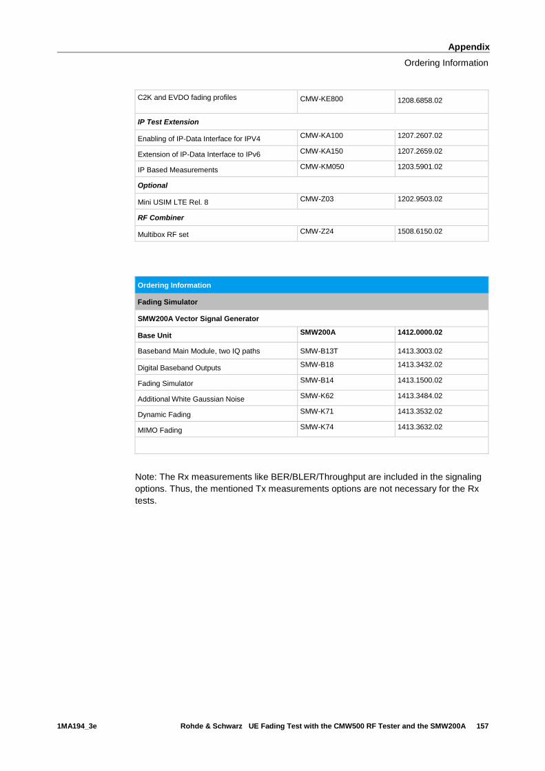
Appendix
Ordering Information
1MA194_3e Rohde & Schwarz UE Fading Test with the CMW500 RF Tester and the SMW200A 157
C2K and EVDO fading profiles
CMW-KE800 1208.6858.02
IP Test Extension
Enabling of IP-Data Interface for IPV4 CMW-KA100 1207.2607.02
Extension of IP-Data Interface to IPv6 CMW-KA150 1207.2659.02
IP Based Measurements CMW-KM050 1203.5901.02
Optional
Mini USIM LTE Rel. 8 CMW-Z03 1202.9503.02
RF Combiner
Multibox RF set CMW-Z24 1508.6150.02
Ordering Information
Fading Simulator
SMW200A Vector Signal Generator
Base Unit SMW200A 1412.0000.02
Baseband Main Module, two IQ paths SMW-B13T 1413.3003.02
Digital Baseband Outputs SMW-B18 1413.3432.02
Fading Simulator SMW-B14 1413.1500.02
Additional White Gaussian Noise SMW-K62 1413.3484.02
Dynamic Fading SMW-K71 1413.3532.02
MIMO Fading SMW-K74 1413.3632.02
Note: The Rx measurements like BER/BLER/Throughput are included in the signaling
options. Thus, the mentioned Tx measurements options are not necessary for the Rx
tests.

Rohde & Schwarz
The Rohde & Schwarz electronics group offers
innovative solutions in the following business fields:
test and measurement, broadcast and media, secure
communications, cybersecurity, radiomonitoring and
radiolocation. Founded more than 80 years ago, this
independent company has an extensive sales and
service network and is present in more than 70
countries.
The electronics group is among the world market
leaders in its established business fields. The
company is headquartered in Munich, Germany. It
also has regional headquarters in Singapore and
Columbia, Maryland, USA, to manage its operations
in these regions.
Regional contact
Europe, Africa, Middle East +49 89 4129 12345 [email protected] North America 1 888 TEST RSA (1 888 837 87 72) [email protected] Latin America +1 410 910 79 88 [email protected] Asia Pacific +65 65 13 04 88 [email protected]
China +86 800 810 82 28 |+86 400 650 58 96 [email protected]
Sustainable product design
ı Environmental compatibility and eco-footprint
ı Energy efficiency and low emissions
ı Longevity and optimized total cost of ownership
This application note and the supplied programs
may only be used subject to the conditions of use
set forth in the download area of the Rohde &
Schwarz website.
R&S® is a registered trademark of Rohde & Schwarz GmbH & Co.
KG; Trade names are trademarks of the owners.
Rohde & Schwarz GmbH & Co. KG
Mühldorfstraße 15 | D - 81671 München
Phone + 49 89 4129 - 0 | Fax + 49 89 4129 – 13777
www.rohde-schwarz.com
PA
D-T
-M: 3573.7
380.0
2/0
2.0
0/C
I/1/E
N/


