
~UNIn:DSTIRLING
Abstract
United Stirling's Solar Engine Development- the background for the Vanguard Engine
Author: Sten HolgerssonUnited Stirling AB Sweden
Introduction
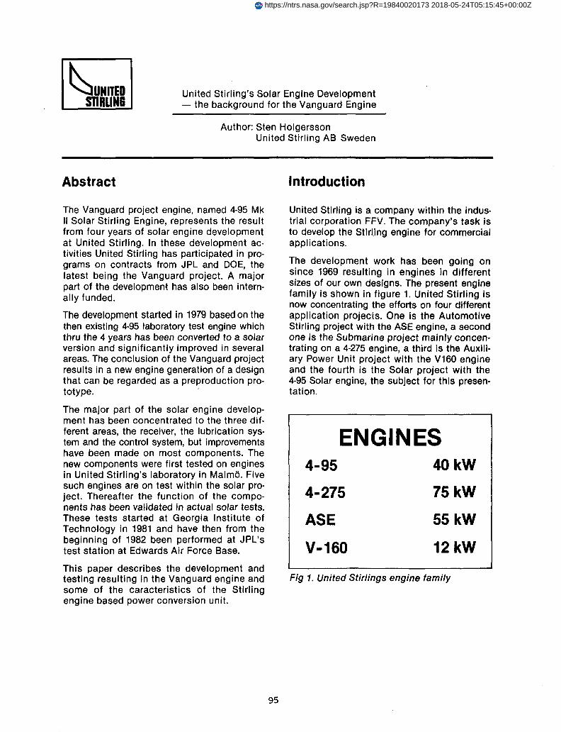
Fig 1. United Stirlings engine family
ENGINES
United Stirling is a company within the industrial corporation FFV. The company's task isto develop the Stirling engine for commercialapplications.
The development work has been going onsince 1969 resulting in engines in differentsizes of our own designs. The present enginefamily is shown in figure 1. United Stirling isnow concentrating the efforts on four differentapplication projects. One is the AutomotiveStirling project with the ASE engine, a secondone ;s the Submarine project mainly concentrating on a 4-275 engine, a third is the Auxiliary Power Unit project with the V160 engineand the fourth is the Solar project with the4-95 Solar engine, the subject for this presentation.
The Vanguard project engine, named 4-95 MkII Solar Stirling Engine, represents the resultfrom four years of solar engine developmentat United Stirling. In these development activities United Stirling has participated in programs on contracts from JPL and DOE, thelatest being the Vanguard project. A majorpart of the development has also been internally funded.
The development started in 1979 based on thethen existing 4-95 laboratory test engine whichthru the 4 years has been converted to a solarversion and significantly improved in severalareas. The conclusion of the Vanguard projectresults in a new engine generation of a designthat can be regarded as a preproduction pro-totype. .
The major part of the solar engine development has been concentrated to the three different areas, the receiver, the lubrication system and the control system, but improvementshave been made on most components. Thenew components were first tested on enginesin United Stirling's laboratory in Malmo. Fivesuch engines are on test within the solar project. Thereafter the function of the components has been validated in actual solar tests.These tests started at Georgia Institute ofTechnology in 1981 and have then from thebeginning of 1982 been performed at JPL'stest station at Edwards Air Force Base.
This paper describes the development andtesting resulting in the Vanguard engine andsome of the caracteristics of the Stirlingengine based power conversion unit.
95
4-95
4-275
ASE
V-160
40kW
75kW
55kW
12kW
https://ntrs.nasa.gov/search.jsp?R=19840020173 2018-05-24T05:15:45+00:00Z

~UNITEDSTIRLlNB
Solar development programs
Although it of course has always been anawareness at United Stirling of the possibilityto use the Stirling engine for solar energy con-version our activities in the field were very lowuntil 1978. We then became participants in aNASA-funded study together with MTI. Thisstudy identified both the kinematic and thefree-piston Stirling engine as viable candidatesfor the solar application. The next year, 1979,we accepted participation in a JPL-program.Our task was to redesign the drive unit to fitto and be able to operate in the EAFB test bedconcentrator and to deliver one drive unitwhile JPL developed the receiver. Participation in this program rose our interest inreceiver design and we decided in 1980 todevelop a receiver design of our own. This wasa natural step since in the Stirling engine thereceiver is an integral part of the engine andour intention was to be capable to deliver acomplete Stirling engine for an application inwhich the commercialization of the enginecould be realized. From 1980 and on our ownextensive solar engine development programhas been going on. In addition to that, and asone of the significant components of our solarengine development we 1982 became members of the Vanguard program which now isbeing realized in hardware in Palm Springsthrough delivery of the concentrator fromAdvanco and the PCU from United Stirling.The Stirling engine in the Vanguard project isthe first engine in the new generation internally at United Stirling called the 4-95 Mk IISolar SE. This engine is of course a productof the Vanguard project, but in reality the result of a much broader development programat United Stirling. This development programis the combination of the Vanguard projectand internally funded solar engine development. A summary of the externally fundedsolar development programs in which we haveparticipated is given in figure 2.
96
USAB SOLAR ACTIVITIES
• NASA STUOY 1978 - 1979
15 KW SOLAR STIRLING ENGINE
• JPL PROJECT 1979 - 1981
INSTALLATION OF THE FIRST SOLARSTIRLING ENGINE WITH HYBRID RECEIVERIN A PARABOLIC DISH
.DOE PROJECT 1982-
TEAM MEMBER OF THE VANGUARD PROJECT
Fig 2. Solar programs
The engine choice forsolar applications: 4-95The development of the Solar Stirling enginehas during the last 3-4 years been concentrated to the 4-95 engine, figure 3. The reasons forchoosing this engine were several. The enginesize fits to a concentrator within the size range,10-18 m diameter, that seems to be most costeffective. The existing JPL test bed concentrator and the 4-95 engine are almost perfectin sizes for each other which means that anopportunity to performe realistic hardwaretests existed. The 4·95 engine was one ofUnited Stirling's engines, that had the highestamount of accumulated running hours withrather good results. Figure 4 shows a summary of the present experience with the 4·95engine.
The 4·95 engine was originally designed as alaboratory test engine in 1975. It has sincethen been used as the baseline engine in thebeginning of the Automotive Stirling Engineprogram and as the first underwater enginedesigned by United Stirling. The further developed 4-95 engine is now chosen as the solarStirling engine.
~UNITEDSTIRLING
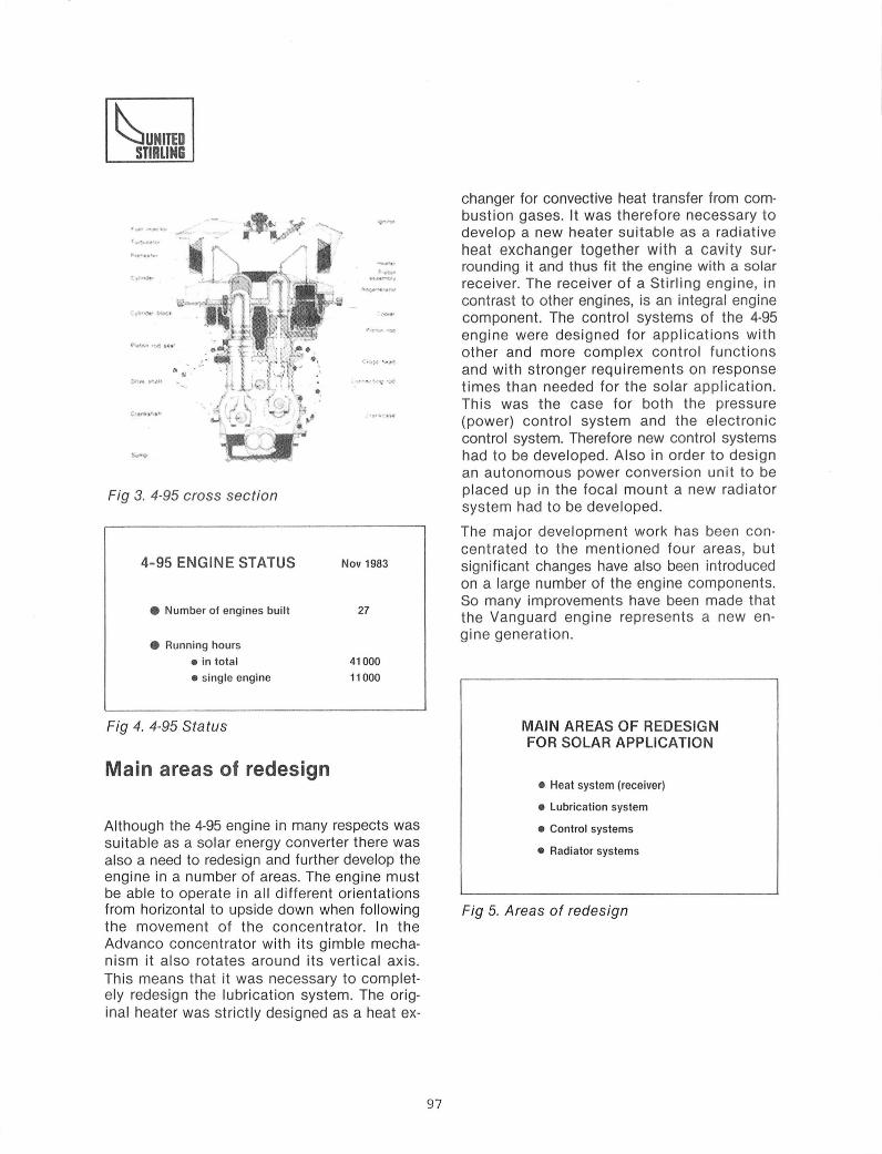
Fig 3. 4-95 cross section
4-95 ENGINE STATUS
• Number of engines built
• Running hours
• in total
• single engine
Fig 4. 4-95 Status
Nov 1983
27
41000
11 000
changer for convective heat transfer from combustion gases. It was therefore necessary todevelop a new heater suitable as a radiativeheat exchanger together with a cavity surrounding it and thus fit the engine with a solarreceiver. The receiver of a Stirling engine, incontrast to other engines, is an integral enginecomponent. The control systems of the 4-95engine were designed for applications withother and more complex control functionsand with stronger requirements on responsetimes than needed for the solar application.This was the case for both the pressure(power) control system and the electroniccontrol system. Therefore new control systemshad to be developed. Also in order to designan autonomous power conversion unit to beplaced up in the focal mount a new radiatorsystem had to be developed.
The major development work has been concentrated to the mentioned four areas, butsignificant changes have also been introducedon a large number of the engine components.So many improvements have been made thatthe Vanguard engine represents a new engine generation .
MAIN AREAS OF REDESIGNFOR SOLAR APPLICATION
Main areas of redesign
Although the 4-95 engine in many respects wassuitable as a solar energy converter there wasalso a need to redesign and further develop theengine in a number of areas. The engine mustbe able to operate in all different orientationsfrom horizontal to upside down when followingthe movement of the concentrator. In theAdvanco concentrator with its gimble mechanism it also rotates around its vertical axis.This means that it was necessary to completely redesign the lubrication system. The original heater was strictly designed as a heat ex-
97
• Heat system (receiver)
• Lubrication system
• Control systems
• Radiator systems
Fig 5. Areas of redesign
~UNITEDSTlRLlNIi
Pressure - MaxLevel
I12:00Noon
I12:00
Midnight
I6:00P.M.
J---,----,------r---..,...-
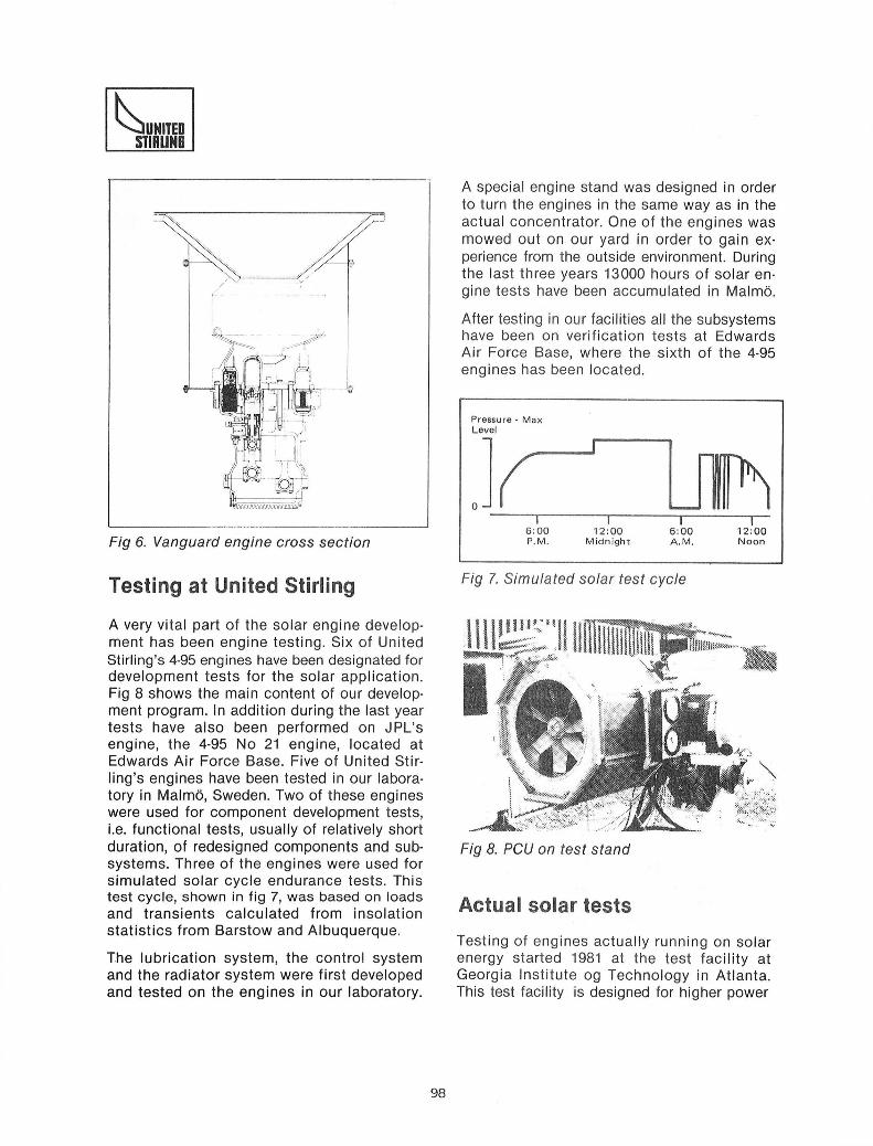
A special engine stand was designed in orderto turn the engines in the same way as in theactual concentrator. One of the engines wasmowed out on our yard in order to gain experience from the outside environment. Duringthe last three years 13000 hours of solar engine tests have been accumulated in Malmo.
After testing in our facilities all the subsystemshave been on verification tests at EdwardsAir Force Base, where the sixth of the 4-95engines has been located.
Fig 6. Vanguard engine cross section'-----------------------'
Testing at United Stirling Fig 7. Simulated solar test cycle
A very vital part of the solar engine development has been engine testing. Six of UnitedStirling's 4-95 engines have been designated fordevelopment tests for the solar application.Fig 8 shows the main content of our development program. In addition during the last yeartests have also been performed on JPL'sengine, the 4-95 No 21 engine, located atEdwards Air Force Base. Five of United Stirling's engines have been tested in our laboratory in Malmo, Sweden. Two of these engineswere used for component development tests,Le. functional tests, usually of relatively shortduration, of redesigned components and subsystems. Three of the engines were used forsimulated solar cycle endurance tests. Thistest cycle, shown in fig 7, was based on loadsand transients calculated from insolationstatistics from Barstow and Albuquerque.
The lubrication system, the control systemand the radiator system were first developedand tested on the engines in our laboratory.
Fig 8. PCU on test stand
Actual solar tests
Testing of engines actually running on solarenergy started 1981 at the test facility atGeorgia Institute og Technology in Atlanta.This test facility is designed for higher power
98
~UNITEDSTIRLING
than the 4-95 engine but testing was possibleto perform by shielding the excessive flux witha watercooled plate. The testing in Atlantagave very useful information for the furtherdevelopment of the receiver and control systems, but in order to evaluate the function ofall components in a matched system therewas still a need to test in a parabolic dish.Therefore the testing was transferred to JPL'stest station at Edwards Air Force Base earlyin 1982 where testing has been going on sincethen jointly with JPL in their test bed concentrator.
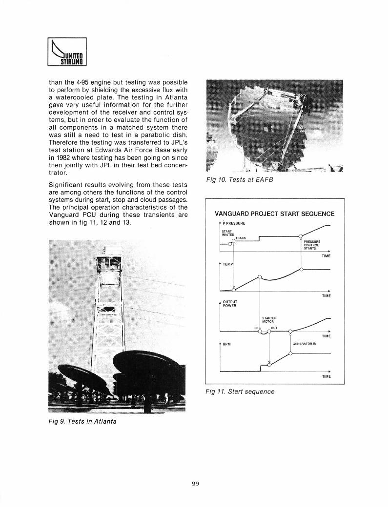
Significant results evolving from these testsare among others the functions of the controlsystems during start, stop and cloud passages.The principal operation characteristics of theVanguard PCU during these transients areshown in fig 11, 12 and 13.
Fig 10. Tests at EAFB
VANGUARD PROJECT START SEQUENCEPPRESSURE
STARTINtATED
TRACK
TIME
TIME
TIME
GENERATOR IN
STARTERMOTOR
IN OUT
TIME
PRESSURECONTROLSTARTS
TEMP
OUTPUTPOWER
RPM
Fig 11. Start sequence
Fig 9. Tests in Atlanta
99

~UNI1EImRUN
VANGUARD PROJECT STOP SEQUENCE VANGUARD PROJECT CLOUD PASSAGE
TIME
TIME
TIME
IiGENERATOR
IN
IIIIII STARTERq MOTOR
II GENERATORlOUT
I PRESSURE I'I CONTROL II I
~.. p.S :. I.. I
I tI
RPM
OUTPUTPOWER
A ~ CLOUD~P PRESSURE I I
IIII
'------------"1---+-------+TIME
TIME
TIME
TIME
TIME
ENGINESTOPS
GENERATOROUT
PRESSURECONTROLSTOPSTEMP
RPM
OUTPUTPOWER
PPRESSURE
Fig 12. Stop sequence Fig 13. Cloud passage
The Vanguard project
4-95 Mk II (VANGUARD)ENGINE OBJECTIVES
• Keep Mk I performance level
• Increase reliability
• Reduce production cost
Fig 14. Vanguard engine objectives
United Stirling became member of the Vanguard project responsible for design and delivery of the power conversion unit. The contract was signed in May 1982. Our task in thisproject has included modification of the 4-95engine in the earlier mentioned areas to fittogether with the Advanco concentrators. Themain objectives for the engine for this projectare shown in fig 14. Laboratory tests have verified that the performance goals are met andcalculations show a reduction of 30% in production costs. Several modifications of components aimed at increased reliability havebeen introduced. The results of these modifications can only be achieved thru future testing of the engine.
The PCU is now delivered to the test site andready for testing.
100
~UNITEDSTIRLING
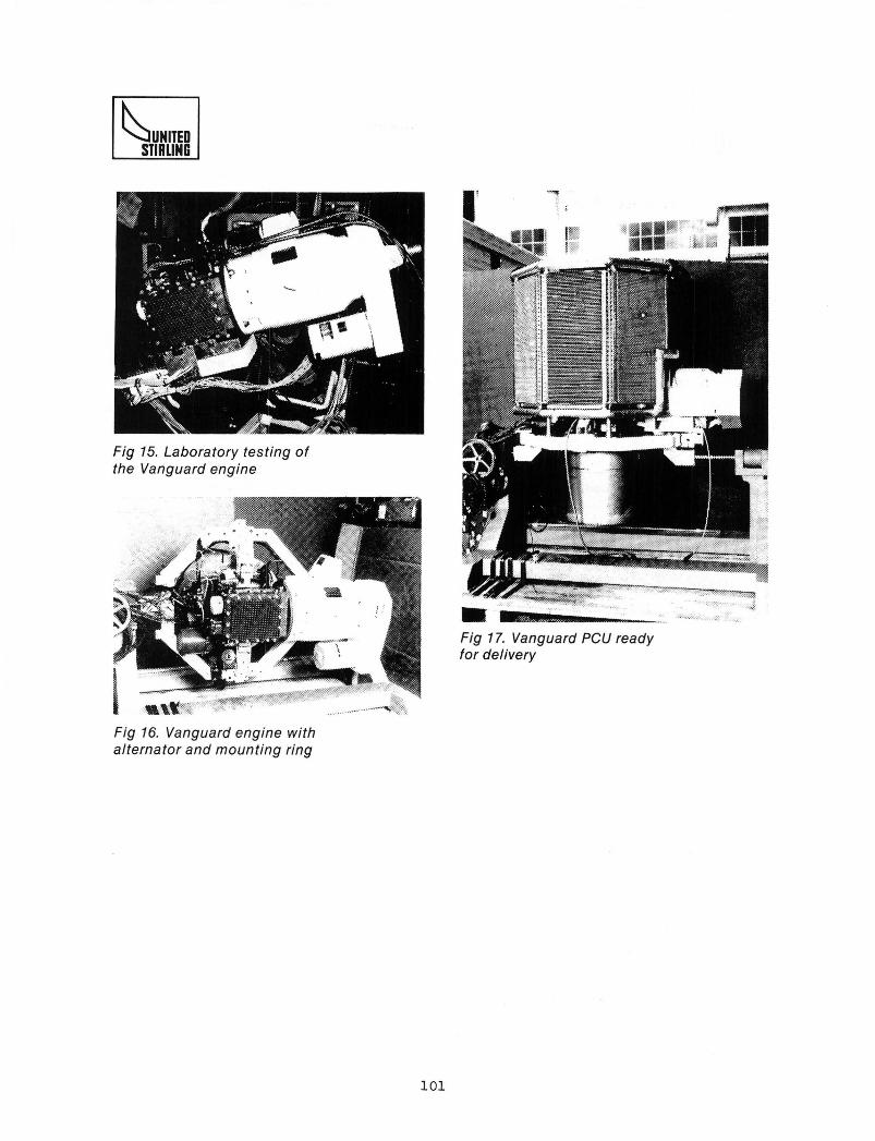
Fig 15. Laboratory testing ofthe Vanguard engine
Fig 16. Vanguard engine withalternator and mounting ring
101
? ";"'".. '.,Fig 17. Vanguard PCU readyfor delivery


