

8/10/2019 unit ii NOTES New Microsoft Office Word 97 - 2003 Document (Autosaved).doc
http://slidepdf.com/reader/full/unit-ii-notes-new-microsoft-office-word-97-2003-document-autosaveddoc 1/56
UNIT-II
ROBOT HARDWARE
Objectives:
To Know the sensors usage in robots
To Understand the concept of Mechanism of robots
Robot sensors
1.Sensors and Transducers
Simple stand alone electronic circuits can be made to repeatedly flash a light
or play a musical note, but in order for an electronic circuit or system to
perform any useful task or function it needs to be able to communicate with
the real world whether this is by reading an input signal from an !N"!##
switch or by acti$ating some form of output de$ice to illuminate a single light
and to do this we use Transducers.
Transducers can be used to sense a wide range of different energy forms
such as mo$ement, electrical signals, radiant energy, thermal or magnetic
energy etc, and there are many different types of both analogue and digital
input and output de$ices a$ailable to choose from. The type of input or
output transducer being used, really depends upon the type of signal or
process being Sensed or %ontrolled but we can define a transducer as a
de$ice that con$erts one physical &uantity into another.
'e$ices which perform an input function are commonly called Sensors
because they sense a physical change in some characteristic that changes
in response to some e(citation, for e(ample heat or force and co$ert that
into an electrical signal. 'e$ices which perform an output function are
generally called Actuators and are used to control some e(ternal de$ice, for
e(ample mo$ement. )oth sensors and actuators are collecti$ely known as
Transducers because they are used to con$ert energy of one kind into
energy of another kind, for e(ample, a microphone *input de$ice+ con$erts
sound wa$es into electrical signals for the amplifier to amplify, and a

8/10/2019 unit ii NOTES New Microsoft Office Word 97 - 2003 Document (Autosaved).doc
http://slidepdf.com/reader/full/unit-ii-notes-new-microsoft-office-word-97-2003-document-autosaveddoc 2/56
loudspeaker *output de$ice+ con$erts the electrical signals back into sound
wa$es and an e(ample of this is gi$en below.
Simple InputOutput S!stem using Sound Transducers
There are many different types of transducers a$ailable in the marketplace,
and the choice of which one to use really depends upon the &uantity being
measured or controlled, with the more common types gi$en in the table
below.
"ommon Transducers
uantity being
easured
Input 'e$ice
*Sensor+
!utput 'e$ice
*ctuator+
/ight /e$el
/ight 'ependant 0esistor
*/'0+
hotodiode
hoto-transistor
Solar %ell
/ights 2 /amps
/3'4s 2 'isplays
#ibre !ptics
Temperature
Thermocouple
Thermistor
Thermostat
0esisti$e temperature
detectors *0T'+
5eater
#an
#orce"ressureStrain 6auge/ifts 2 7acks

8/10/2019 unit ii NOTES New Microsoft Office Word 97 - 2003 Document (Autosaved).doc
http://slidepdf.com/reader/full/unit-ii-notes-new-microsoft-office-word-97-2003-document-autosaveddoc 3/56
ressure Switch
/oad %ells
3lectromagnet
8ibration
osition
otentiometer
3ncoders
0eflecti$e"Slotted !pto-
switch
/8'T
otor
Solenoid
anel eters
Speed
Tacho-generator
0eflecti$e"Slotted !pto-
coupler
'oppler 3ffect Sensors
% and '% otors
Stepper otor
)rake
Sound%arbon icrophone
ie9o-electric %rystal
)ell
)u99er
/oudspeaker
Input type transducers or sensors, produce a proportional output $oltage or
signal in response to changes in the &uantity that they are measuring *the
stimulus+ and the type or amount of the output signal depends upon the
type of sensor being used. 6enerally, all types of sensors can be classed as
two kinds, passive and active.
cti$e sensors re&uire some form of e(ternal power to operate, called an
excitation signal which is used by the sensor to produce the output signal.
cti$e sensors are self-generating de$ices because their own properties
change in response to an e(ternal effect and produce an output $oltage, for
e(ample, 1 to 1:$ '% or an output current such as ; to <:m '%. #or
e(ample, a strain gauge is a pressure-sensiti$e resistor. It does not generate
any electrical signal, but by passing a current through it *e(citation signal+,
its resistance can be measured by detecting $ariations in the current and"or
$oltage across it relating these changes to the amount of strain or force.
Unlike the acti$e sensor, a passi$e sensor does not need any additional
energy source and directly generates an electric signal in response to an

8/10/2019 unit ii NOTES New Microsoft Office Word 97 - 2003 Document (Autosaved).doc
http://slidepdf.com/reader/full/unit-ii-notes-new-microsoft-office-word-97-2003-document-autosaveddoc 4/56
e(ternal stimulus. #or e(ample, a thermocouple or photodiode. assi$e
sensors are direct sensors which change their physical properties, such as
resistance, capacitance or inductance etc. s well as analogue sensors,
#igital Sensors produce a discrete output representing a binary number or
digit such as a logic le$el : or a logic le$el 1.
nalogue and 'igital Sensors
$%$%Analogue Sensors
Analogue Sensors produce a continuous output signal or $oltage which is
generally proportional to the &uantity being measured. hysical &uantities
such as Temperature, Speed, ressure, 'isplacement, Strain etc are all
analogue &uantities as they tend to be continuous in nature. #or e(ample,
the temperature of a li&uid can be measured using a thermometer or
thermocouple which continuously responds to temperature changes as the
li&uid is heated up or cooled down.
Thermocouple used to produce an Analogue Signal

8/10/2019 unit ii NOTES New Microsoft Office Word 97 - 2003 Document (Autosaved).doc
http://slidepdf.com/reader/full/unit-ii-notes-new-microsoft-office-word-97-2003-document-autosaveddoc 5/56
nalogue sensors tend to produce output signals that are changing smoothly
and continuously which are $ery small in $alue so some form of amplification
is re&uired. Then circuits which measure analogue signals usually ha$e a
slow response and"or low accuracy. lso analogue signals can be easily
con$erted into digital type signals for use in microcontroller systems by the
use of analogue-to-digital con$erters, or '%4s.
$%$%&%#igital Sensors
s its name implies, #igital Sensors produce a discrete output signal or
$oltage that is a digital representation of the &uantity being measured.
'igital sensors produce a 'inar! output signal in the form of a logic 1 or a
logic :, *!N or !##+. This means then that a digital signal only
produces discrete *non-continuous+ $alues which may be outputted as a
single bit, *serial transmission+ or by combining the bits to produce a
single byte output *parallel transmission+.
(ight Sensor used to produce an #igital Signal

8/10/2019 unit ii NOTES New Microsoft Office Word 97 - 2003 Document (Autosaved).doc
http://slidepdf.com/reader/full/unit-ii-notes-new-microsoft-office-word-97-2003-document-autosaveddoc 6/56
In our simple e(ample abo$e, the speed of the rotating shaft is measured by
using a digital /3'"!pto-detector sensor. The disc which is fi(ed to a rotating
shaft *for e(ample, from a motor or wheels+, has a number of transparent
slots within its design. s the disc rotates with the speed of the shaft, each
slot passes by the sensor inturn producing an output pulse representing a
logic le$el 1. These pulses are sent to a register of counter and finally to
an output display to show the speed or re$olutions of the shaft. )y
increasing the number of slots or windows within the disc more output
pulses can be produced gi$ing a greater resolution and accuracy as fractions
of a re$olution can be detected. Then this type of sensor arrangement could
be used for positional control.
%ompared to analogue signals, digital signals or &uantities ha$e $ery high
accuracies and can be both measured and sampled at a $ery high clock
speed. The accuracy of the digital signal is proportional to the number of bits
used to represent the measured &uantity. #or e(ample, using a processor of
= bits, will produce an accuracy of :.1>?@ *1 part in ?1<+. Ahile using a
processor of 1B bits gi$es an accuracy of :.::1?@, *1 part in B?,?CB+ or 1C:
times more accurate. This accuracy can be maintained as digital &uantities
are manipulated and processed $ery rapidly, millions of times faster than
analogue signals.

8/10/2019 unit ii NOTES New Microsoft Office Word 97 - 2003 Document (Autosaved).doc
http://slidepdf.com/reader/full/unit-ii-notes-new-microsoft-office-word-97-2003-document-autosaveddoc 7/56
In most cases, sensors and more specifically analogue sensors generally
re&uire an e(ternal power supply and some form of additional amplification
or filtering of the signal in order to produce a suitable electrical signal which
is capable of being measured or used. !ne $ery good way of achie$ing both
amplification and filtering within a single circuit is to use Operational
Amplifiers as seen before.
Signal %onditioning
s we saw in the Operational Amplifier tutorial, op-amps can be used to
pro$ide amplification of signals when connected in either in$erting or non-
in$erting configurations. The $ery small analogue signal $oltages produced
by a sensor such as a few milli-$olts or e$en pico-$olts can be amplified
many times o$er by a simple op-amp circuit to produce a much larger
$oltage signal of say ?$ or ?m that can then be used as an input signal to a
microprocessor or analogue-to-digital based system. Therefore, an
amplification of a sensors output signal has to be made with a $oltage gain
up to 1:,::: and a current gain up to 1,:::,::: with the amplification of
the signal being linear with the output signal being an e(act reproduction of
the input, Dust changed in amplitude. Then amplification is part of signalconditioning. So when using analogue sensors, generally some form of
amplification *6ain+, impedance matching, isolation between the input and
output or perhaps filtering *fre&uency selection+ may be re&uired before the
signal can be used and this is con$eniently performed by Operational
Amplifiers.
lso, when measuring $ery small physical changes the output signal of a
sensor can become contaminated with unwanted signals or $oltages thatpre$ent the actual signal re&uired from being measured correctly. These
unwanted signals are called )oise. This Noise or Interference can be
either greatly reduced or e$en eliminated by using signal conditioning or
filtering techni&ues as we discussed in the Active *ilter tutorial. )y using

8/10/2019 unit ii NOTES New Microsoft Office Word 97 - 2003 Document (Autosaved).doc
http://slidepdf.com/reader/full/unit-ii-notes-new-microsoft-office-word-97-2003-document-autosaveddoc 8/56
either a (ow +ass, or a ,igh +ass or e$en 'and +ass filter the
bandwidth of the noise can be reduced to lea$e Dust the output signal
re&uired. #or e(ample, many types of inputs from switches, keyboards or
manual controls are not capable of changing state rapidly and so low-pass
filter can be used. Ahen the interference is at a particular fre&uency, for
e(ample mains fre&uency, narrow band reDect or )otch filters can be used
to produce fre&uency selecti$e filters. Ahere some random noise still
remains after filtering it may be necessary to take se$eral samples and then
a$erage them to gi$e the final $alue so increasing the signal-to-noise ratio.
Op-amp *ilters
3ither way, both amplification and filtering play an important role in
interfacing microprocessor and electronics based systems to real world
conditions. In the ne(t tutorial about Sensors, we will look at +ositional
Sensors which measure the position and"or displacement of physical obDects
meaning the mo$ement from one position to another for a specific distance
or angle.
$%&%+ro.imit! Sensors
ro(imity sensors may be of the contact or non-contact type. %ontact
pro(imity sensors are the least e(pensi$e. ro(imity sensors can ha$e one
of many technology types. These include capaciti$e, eddy current,
inducti$e, photoelectric, ultrasonic, and 5all effect. %apaciti$e pro(imity
sensors utili9e the face or surface of the sensor as one plate of a capacitor,
and the surface of a conducti$e or dielectric target obDect as the other. The
capacitance $aries in$ersely with the distance between capacitor plates in
8/10/2019 unit ii NOTES New Microsoft Office Word 97 - 2003 Document (Autosaved).doc
http://slidepdf.com/reader/full/unit-ii-notes-new-microsoft-office-word-97-2003-document-autosaveddoc 9/56
this arrangement, and a certain $alue can be set to trigger target
detection. In an eddy current pro(imity sensor electrical currents are
generated in a conducti$e material by an induced magnetic field.
Interruptions in the flow of the electric currents *eddy currents+, which are
caused by imperfections or changes in a material4s conducti$e properties,
will cause changes in the induced magnetic field. These changes, when
detected, indicate the presence of change in the test obDect. agnetic
inducti$e de$ices are identical in configuration to the $ariable reluctance
type and generate the same type of signal. 5owe$er, inducti$e pickoff coils
ha$e no internal permanent magnet and rely on e(ternal magnetic field
fluctuations, such as a rotating permanent magnet, in order to generate
signal pulse. hotoelectric de$ices are used to detect $arious materials at
long range, using a beam of light. They detect either the presence or
absence of light and use this information to read the data from the output
transistor. n ultrasonic pro(imity sensor emits an ultrasonic pulse, which is
reflected by surface and returned to sensor. Speed can be determined by
measuring fre&uency difference *'oppler 3ffect+. The basic 5all 3ffect
sensing element is a semiconductor de$ice which, when electrical current issent through it, will generate an electrical $oltage proportional to the
magnitude of a magnetic field flowing perpendicular to the surface of the
semiconductor.
The most important parameter to consider when specifying pro(imity
sensors is the operating distance. This is the rated operating distance is the
distance at which switching takes place. %ommon body styles for pro(imitysensors are barrel, limit switch, rectangular, slot style, and ring. Important
dimensions to consider when specifying pro(imity sensors include barrel
diameter, length, width, and height.

8/10/2019 unit ii NOTES New Microsoft Office Word 97 - 2003 Document (Autosaved).doc
http://slidepdf.com/reader/full/unit-ii-notes-new-microsoft-office-word-97-2003-document-autosaveddoc 10/56
ro(imity sensors can be a sensor element or chip, a sensor or transducer,
an instrument or meter, a gauge or indicator, a recorder or totali9er, and a
controller. sensor element or chip denotes a raw de$ice such as a strain
gage, or one with no integral signal conditioning or packaging. sensor or
transducer is a more comple( de$ice with packaging and"or signal
conditioning that is powered and pro$ides an output such a dc $oltage, a ;-
<:m current loop, etc. n instrument or meter is a self-contained unit that
pro$ides an output such as a display locally at or near the de$ice. Typically
also includes signal processing and"or conditioning. gauge or indicator is a
de$ice that has a *usually analog+ display and no electronic output such as a
tension gage. recorder or totali9er is an instrument that records, totali9es,
or tracks force measurement o$er time. Includes simple datalogging
capability or ad$anced features such as mathematical functions, graphing,
etc.
+ro.imit! Sensors
- ro(imity Sensors !$er$iew
- %apaciti$e ro(imity Sensors
- Inducti$e ro(imity Sensors- agnetic ro(imity Sensors
%apaciti$e Sensor Theory, !peration, and !ptimi9ation
$%&%$%"apacitance and #istance
Noncontact capaciti$e sensors work by measuring changes in an electrical
property called capacitance. %apacitance describes how two conducti$e
obDects with a space between them respond to a $oltage difference applied
to them. Ahen a $oltage is applied to the conductors, an electric field iscreated between them causing positi$e and negati$e charges to collect on
each obDect *#ig. 1+. If the polarity of the $oltage is re$ersed, the charges
will also re$erse.

8/10/2019 unit ii NOTES New Microsoft Office Word 97 - 2003 Document (Autosaved).doc
http://slidepdf.com/reader/full/unit-ii-notes-new-microsoft-office-word-97-2003-document-autosaveddoc 11/56
#igure <
pplying an alternating $oltage causes
the charges to mo$e back and forth
between the obDects, creating an alternating
current which is detected by the sensor.
%apaciti$e sensors use an alternating $oltage which causes the charges tocontinually re$erse their positions. The mo$ing of the charges creates an
alternating electric current which is detected by the sensor *#ig. <+. The
amount of current flow is determined by the capacitance, and the
capacitance is determined by the area and pro(imity of the conducti$e

8/10/2019 unit ii NOTES New Microsoft Office Word 97 - 2003 Document (Autosaved).doc
http://slidepdf.com/reader/full/unit-ii-notes-new-microsoft-office-word-97-2003-document-autosaveddoc 12/56
obDects. /arger and closer obDects cause greater current than smaller and
more distant obDects. The capacitance is also affected by the type of
nonconducti$e material in the gap between the obDects.
Technically speaking, the capacitance is directly proportional to the surface
area of the obDects and the dielectric constant of the material between them,
and in$ersely proportional to the distance between them *#ig. C+.
In typical capaciti$e sensing applications, the probe or sensor is one of the
conducti$e obDectsE the target obDect is the other. *Using capaciti$e sensors
to sense plastics and other insulators is discussed in the nonconducti$e
targets section.+ The si9es of the sensor and the target are assumed to be
constant as is the material between them. Therefore, any change in
capacitance is a result of a change in the distance between the probe and
the target. The electronics are calibrated to generate specific $oltage
changes for corresponding changes in capacitance. These $oltages are scaled
to represent specific changes in distance. The amount of $oltage change for
a gi$en amount of distance change is called the sensiti$ity. common
sensiti$ity setting is 1.:8"1::Fm. That means that for e$ery 1::Fm change
in distance, the output $oltage changes e(actly 1.:8. Aith this calibration, aG<8 change in the output means that the target has mo$ed <::Fm closer to
the probe.
*ocusing the /lectric *ield
#igure ;
%apaciti$e sensor probe components

8/10/2019 unit ii NOTES New Microsoft Office Word 97 - 2003 Document (Autosaved).doc
http://slidepdf.com/reader/full/unit-ii-notes-new-microsoft-office-word-97-2003-document-autosaveddoc 13/56
#igure ? %utaway $iew showing an unguarded sensing area electric field
#igure B
%utaway showing the guard field shaping the sensing area electric field
Ahen a $oltage is applied to a conductor, the electric field emanates from
e$ery surface. In a capaciti$e sensor, the sensing $oltage is applied to the
Sensing rea of the probe *#igs. ;, ?+.
#or accurate measurements, the electric field from the sensing area needs to
be contained within the space between the probe and the target. If the
electric field is allowed to spread to other items or other areas on the target
then a change in the position of the other item will be measured as a change
in the position of the target.
techni&ue called Hguarding is used to pre$ent this from happening. To
create a guard, the back and sides of the sensing area are surrounded by
another conductor that is kept at the same $oltage as the sensing area itself
*#ig. ;, B+.
Ahen the $oltage is applied to the sensing area, a separate circuit applies
the e(act same $oltage to the guard. )ecause there is no difference in
8/10/2019 unit ii NOTES New Microsoft Office Word 97 - 2003 Document (Autosaved).doc
http://slidepdf.com/reader/full/unit-ii-notes-new-microsoft-office-word-97-2003-document-autosaveddoc 14/56
$oltage between the sensing area and the guard, there is no electric field
between them. ny other conductors beside or behind the probe form an
electric field with the guard instead of the sensing area. !nly the unguarded
front of the sensing area is allowed to form an electric field with the target.
/ffects of Target Si0e
The target si9e is a primary consideration when selecting a probe for a
specific application. Ahen the sensing electric field is focused by guarding, it
creates a slightly conical field that is a proDection of the sensing area. The
minimum target diameter for standard calibration is C:@ of the diameter of
the sensing area. The further the probe is from the target, the larger the
minimum target si9e.
1ange of Measurement
In general, the ma(imum gap at which a probe is useful is appro(imately
;:@ of the sensor diameter. Standard calibrations usually keep the gap
considerably less than that.
The range in which a probe is useful is a function of the si9e of the sensing
area. The greater the area, the larger the range. The dri$er electronics are
designed for a certain amount of capacitance at the probe. Therefore, asmaller probe must be considerably closer to the target to achie$e the
desired amount of capacitance. The electronics are adDustable during
calibration but there is a limit to the range of adDustment.
In general, the ma(imum gap at which a probe is useful is appro(imately
;:@ of the sensing area diameter. Standard calibrations usually keep the
gap considerably less than that.
Multiple "hannel SensingUsing multiple probes on the same target re&uires that the e(citation
$oltages be synchroni9ed. This is accomplished by configuring one dri$er as
a master and others as sla$es.

8/10/2019 unit ii NOTES New Microsoft Office Word 97 - 2003 Document (Autosaved).doc
http://slidepdf.com/reader/full/unit-ii-notes-new-microsoft-office-word-97-2003-document-autosaveddoc 15/56
#re&uently, a target is measured simultaneously by multiple probes. )ecause
the system measures a changing electric field, the e(citation $oltage for
each probe must be synchroni9ed or the probes would interfere with each
other. If they were not synchroni9ed, one probe would be trying to increase
the electric field while another was trying to decrease it thereby gi$ing a
false reading.
'ri$er electronics can be configured as masters or sla$es. The master sets
the synchroni9ation for the sla$es in multiple channel systems.
(inear 2ariable #ifferential Transformer
!ne type of positional sensor that does not suffer from mechanical wear
problems is the /inear 8ariable 'ifferential Transformer or LVDT for short.
This is an inducti$e type position sensor which works on the same principle
as the % transformer that is used to measure mo$ement. It is a $ery
accurate de$ice for measuring linear displacement and whose output is
proportional to the position of its mo$eable core.
It basically consists of three coils wound on a hollow tube former, one
forming the primary coil and the other two coils forming identical
secondaries connected electrically together in series but 1=:
o
out of phaseeither side of the primary coil. mo$eable soft iron ferromagnetic core
*sometimes called an armature+ which is connected to the obDect being
measured, slides or mo$es up and down inside the tube. small %
reference $oltage called the e(citation signal *< - <:8 rms, < - <:k59+ is
applied to the primary winding which inturn induces an 3# signal into the
two adDacent secondary windings *transformer principles+.
If the soft iron magnetic core armature is e(actly in the centre of the tubeand the windings, null position, the two induced emf4s in the two
secondary windings cancel each other out as they are 1=: o out of phase, so
the resultant output $oltage is 9ero. s the core is displaced slightly to one
side or the other from this null or 9ero position, the induced $oltage in one of
8/10/2019 unit ii NOTES New Microsoft Office Word 97 - 2003 Document (Autosaved).doc
http://slidepdf.com/reader/full/unit-ii-notes-new-microsoft-office-word-97-2003-document-autosaveddoc 16/56
the secondaries will be become greater than that of the other secondary and
an output will be produced. The polarity of the output signal depends upon
the direction and displacement of the mo$ing core. The greater the
mo$ement of the soft iron core from its central null position the greater will
be the resulting output signal. The result is a differential $oltage output
which $aries linearly with the cores position. Therefore, the output signal has
both an amplitude that is a linear function of the cores displacement and a
polarity that indicates direction of mo$ement. The phase of the output signal
can be compared to the primary coil e(citation phase enabling suitable
electronic circuits such as the '?>< /8'T Sensor mplifier to know which
half of the coil the magnetic core is in and thereby know the direction of
tra$el.
The (inear 2ariable #ifferential Transformer

8/10/2019 unit ii NOTES New Microsoft Office Word 97 - 2003 Document (Autosaved).doc
http://slidepdf.com/reader/full/unit-ii-notes-new-microsoft-office-word-97-2003-document-autosaveddoc 17/56
Ahen the armature is mo$ed from one end to the other through the centre
position the output $oltages changes from ma(imum to 9ero and back to
ma(imum again but in the process changes its phase angle by 1=: deg4s.
This enables the /8'T to produce an output % signal whose magnitude
represents the amount of mo$ement from the centre position and whose
phase angle represents the direction of mo$ement of the core. typicalapplication of this type of sensor would be a pressure transducers, were the
pressure being measured pushes against a diaphragm to produce a force.
d$antages of the linear $ariable differential transformer, or /8'T compared
to a resisti$e potentiometer are that its linearity, that is its $oltage output to

8/10/2019 unit ii NOTES New Microsoft Office Word 97 - 2003 Document (Autosaved).doc
http://slidepdf.com/reader/full/unit-ii-notes-new-microsoft-office-word-97-2003-document-autosaveddoc 18/56
displacement is e(cellent, $ery good accuracy, good resolution, high
sensiti$ity as well as frictionless operation and is sealed against hostile
en$ironments.
Inductive +ro.imit! Sensors%
nother type of inducti$e sensor in common use is the Inductive
+ro.imit! Sensor also called an Eddy current sensor . Ahile they do not
actually measure displacement or angular rotation they are mainly used to
detect the presence of an obDect in front of them or within a close pro(imity,
hence the name pro(imity sensors.
ro(imity sensors, are non-contact de$ices that use a magnetic field for
detection with the simplest magnetic sensor being the reed switch. In an
inducti$e sensor, a coil is wound around an iron core within an
electromagnetic field to form an inducti$e loop. Ahen a ferromagnetic
material is placed within the eddy current field generated around the sensor,
such as a ferromagnetic metal plate or metal screw, the inductance of the
coil changes significantly. The pro(imity sensors detection circuit detects this
change producing an output $oltage. Therefore, inducti$e pro(imity sensors
operate under the electrical principle of *arada!3s (aw of inductance.Inductive +ro.imit! Sensors

8/10/2019 unit ii NOTES New Microsoft Office Word 97 - 2003 Document (Autosaved).doc
http://slidepdf.com/reader/full/unit-ii-notes-new-microsoft-office-word-97-2003-document-autosaveddoc 19/56
n inducti$e pro(imity sensor has four main componentsE The oscillator
which produces the electromagnetic field, the coil which generates the
magnetic field, the detection circuit which detects any change in the field
when an obDect enters it and the output circuit which produces the output
signal, either with normally closed *N%+ or normally open *N!+ contacts.
Inducti$e pro(imity sensors allow for the detection of metallic obDects in
front of the sensor head without any physical contact of the obDect itself
being detected. This makes them ideal for use in dirty or wet en$ironments.
The sensing range of pro(imity sensors is $ery small, typically :.1mm to
1<mm.
+ro.imit! Sensor applications
s well as industrial applications, inducti$e pro(imity sensors are also used
to control the changing of traffic lights at Dunctions and cross roads.
0ectangular inducti$e loops of wire are buried into the tarmac road surface
and when a car or other road $ehicle passes o$er the loop, the metallic body
of the $ehicle changes the loops inductance and acti$ates the sensor thereby
alerting the traffic lights controller that there is a $ehicle waiting.
!ne main disadvantage of these types of sensors is that they are !mni-
directional, that is they will sense a metallic obDect either abo$e, below or to
the side of it. lso, they do not detect non-metallic obDects although
"apacitive +ro.imit! Sensors and Ultrasonic +ro.imit! Sensors are
a$ailable. !ther commonly a$ailable magnetic position sensor include reed
switches, hall effect sensors and $ariable reluctance sensors.
0otary 3ncoders.
Magnetic Transducers

8/10/2019 unit ii NOTES New Microsoft Office Word 97 - 2003 Document (Autosaved).doc
http://slidepdf.com/reader/full/unit-ii-notes-new-microsoft-office-word-97-2003-document-autosaveddoc 20/56
The Sound Transducer
Sound is the general name gi$en to acoustic wa$es that ha$e fre&uencies
ranging from Dust 159 up to many tens of thousands of 5ert9 with the upper
limit of human hearing being around the <: k59, *<:,:::59+ range. Sound is
basically made up from mechanical $ibrations produced by a Sound
Transducer to generate the acoustic wa$es and for sound to be heard it
re&uires a medium for transmission either through the air, a li&uid, or a
solid. lso, sound need not be a continuous fre&uency sound wa$e such as a
single tone or a musical note, but may be an acoustic wa$e made from a
mechanical $ibration, noise or e$en a single pulse of sound such as a bang.
+ie0o Sound Transducer
Sound Transducers include both sensors, that con$ert sound into and
electrical signal such as a microphone, and actuators that con$ert theelectrical signals back into sound such as a loudspeaker. Ae tend to think of
sound as only e(isting in the range of fre&uencies detectable by the human
ear, from <:59 up to <:k59 *a typical loudspeaker fre&uency response+ but
sound transducers can both detect and transmit sound from $ery low
fre&uencies called infra-sound up to $ery high fre&uencies called ultrasound .
)ut in order for a sound transducer to either detect or produce sound we
first need to understand what sound isJ.Sound is basically a wa$eform that is produced by some form of a
mechanical $ibration such as a tuning fork, and which has a fre&uency
determined by the origin of the sound for e(ample, a bass drum has a low
fre&uency sound while a cymbal has a higher fre&uency sound. sound

8/10/2019 unit ii NOTES New Microsoft Office Word 97 - 2003 Document (Autosaved).doc
http://slidepdf.com/reader/full/unit-ii-notes-new-microsoft-office-word-97-2003-document-autosaveddoc 21/56
wa$eform has the same characteristics as that of an electrical wa$eform
which are 4avelength *K+, *re5uenc! *L+ and 2elocit! *m"s+. )oth the
sounds fre&uency and wa$e shape are determined by the origin or $ibration
that originally produced the sound but the $elocity is dependent upon the
medium of transmission *air, water etc.+ that carries the sound wa$e. The
relationship between wa$elength, $elocity and fre&uency is gi$en below as
Sound 4ave 1elationship
• Ahere
•
• Aa$elength is the time period of one complete cycle in Seconds.
•
• #re&uency is the number of wa$elengths per second in 5ert9.
•
• 8elocity is the speed of sound through a transmission medium in m"s-
1.
1.<.C.The icrophone TransducerThe Microphone is a sound transducer that can be classed as a sound
sensor that produces an electrical analogue output signal which is
proportional to the acoustic sound wa$e acting upon its fle(ible diaphragm.
This signal is an electrical image representing the characteristics of the

8/10/2019 unit ii NOTES New Microsoft Office Word 97 - 2003 Document (Autosaved).doc
http://slidepdf.com/reader/full/unit-ii-notes-new-microsoft-office-word-97-2003-document-autosaveddoc 22/56
acoustic wa$eform. 6enerally, the output signal from a microphone is an
analogue signal either in the form of a $oltage or current which is
proportional to the actual sound wa$e.
The most common types of microphones a$ailable as sound transducers are
Dynamic , Electret Condenser , Ribbon and the newer Piezo-electric Crystal
types. Typical applications for microphones as a sound transducer include
audio recording, reproduction, broadcasting as well as telephones, tele$ision,
digital computer recording and body scanners, where ultrasound is used in
medical applications. n e(ample of a simple 'ynamic microphone is
shown below.
#!namic Moving-coil Microphone Sound Transducer
The construction of a dynamic microphone resembles that of a loudspeaker,
but in re$erse. It is a mo$ing coil type microphone which has a $ery smallcoil of thin wire suspended within the magnetic field of a permanent magnet.
s the sound wa$e hits the fle(ible diaphragm, the diaphragm mo$es back
and forth in response to the sound pressure acting upon it, and the attached
coil of wire also mo$es within the magnetic field of the magnet. The
8/10/2019 unit ii NOTES New Microsoft Office Word 97 - 2003 Document (Autosaved).doc
http://slidepdf.com/reader/full/unit-ii-notes-new-microsoft-office-word-97-2003-document-autosaveddoc 23/56
resultant output $oltage signal from the coil is proportional to the pressure
of the sound wa$e acting upon the diaphragm so the louder or stronger the
sound wa$e the larger the output signal will be, making this type of
microphone design pressure sensiti$e.
s the coil of wire is usually $ery small the range of mo$ement of the coil
and attached diaphragm is also $ery small producing a $ery linear output
signal which is >:o out of phase to the sound signal. lso, because the coil is
a low impedance inductor, the output $oltage signal is also $ery low so some
form of pre-amplification of the signal is re&uired.
s the construction of this type of microphone resembles that of a
loudspeaker, it is also possible to use an actual loudspeaker as a
microphone. !b$iously, the a$erage &uality of a loudspeaker will not be as
good as that for a studio type recording microphone but the fre&uency
response of a reasonable speaker is actually better than that of a cheap
freebie microphone. lso the coils impedance of a typical loudspeaker is
different at between = to 1BM. %ommon applications where speakers are
generally used as microphones are in intercoms and walki-talkie4s.
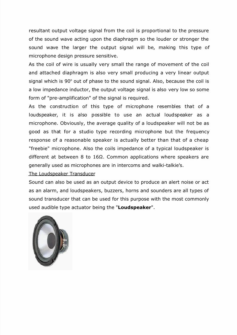
The /oudspeaker TransducerSound can also be used as an output de$ice to produce an alert noise or act
as an alarm, and loudspeakers, bu99ers, horns and sounders are all types of
sound transducer that can be used for this purpose with the most commonly
used audible type actuator being the (oudspea6er.

8/10/2019 unit ii NOTES New Microsoft Office Word 97 - 2003 Document (Autosaved).doc
http://slidepdf.com/reader/full/unit-ii-notes-new-microsoft-office-word-97-2003-document-autosaveddoc 24/56
(oudspea6er Transducer
/oudspeakers are also sound transducers that are classed as sound
actuators and are the e(act opposite of microphones. Their Dob is to con$ert
comple( electrical analogue signals into sound wa$es being as close to the
original input signal as possible. /oudspeakers are a$ailable in all shapes,
si9es and fre&uency ranges with the more common types being mo$ing coil,
electrostatic, isodynamic and pie9o-electric. o$ing coil type loudspeakers
are by far the most commonly used speaker in electronic circuits and kits,
and it is this type of sound transducer we will e(amine below.
The principle of operation of the Moving "oil (oudspea6er is the e(act
opposite to that of the 'ynamic icrophone we look at abo$e. coil of fine
wire, called the speech or $oice coil, is suspended within a $ery strong
magnetic field, and is attached to a paper or ylar cone, called a
diaphragm which itself is suspended at its edges to a metal frame or
chassis. Then unlike the microphone which is pressure sensiti$e, this type of
sound transducer is a pressure generating de$ice.
Moving "oil (oudspea6er

8/10/2019 unit ii NOTES New Microsoft Office Word 97 - 2003 Document (Autosaved).doc
http://slidepdf.com/reader/full/unit-ii-notes-new-microsoft-office-word-97-2003-document-autosaveddoc 25/56
Ahen an analogue signal passes through the $oice coil of the speaker, an
electro-magnetic field is produced and whose strength is determined by the
current flowing through the $oice coil, which inturn is determined by the
$olume control setting of the dri$ing amplifier. The electro-magnetic force
produced by this field opposes the main permanent magnetic field around it
and tries to push the coil in one direction or the other depending upon the
interaction between the north and south poles. s the $oice coil is
permanently attached to the cone"diaphragm this also mo$es in tandem and
its mo$ement causes a disturbance in the air around it thus producing a
sound or note. If the input signal is a continuous sine wa$e then the cone
will mo$e in and out acting like a piston pushing and pulling the air as it
mo$es and a continuous single tone will be heard representing the fre&uency

8/10/2019 unit ii NOTES New Microsoft Office Word 97 - 2003 Document (Autosaved).doc
http://slidepdf.com/reader/full/unit-ii-notes-new-microsoft-office-word-97-2003-document-autosaveddoc 26/56
of the signal. The strength and therefore its $elocity, by which the cone
mo$es and pushes the surrounding air produces the loudness of the sound.
s the speech or $oice coil is essentially a coil of wire it has, like an inductor
an impedance $alue. This $alue for most loudspeakers is between ; and
1BM4s and is called the nominal impedance $alue of the speaker measured
at :59, or '% It is important to always match the output impedance of the
amplifier with the nominal impedance of the speaker to obtain ma(imum
power transfer between the amplifier and speaker with most amplifier-
speaker combinations ha$ing and efficiency rating as low as 1 or <@.
lthough disputed by some, the selection of good speaker cable is also an
important factor in the efficiency of the speaker, as the internal capacitance
and magnetic flu( characteristics of the cable change with the signal
fre&uency, thereby causing both fre&uency and phase distortion attenuating
the input signal. lso, with high power amplifiers large currents are flowing
through these cables so small thin bell wire type cables can o$erheat during
long periods of use.
The human ear can generally hear sounds from between <:59 to <:k59, and
the fre&uency response of modern loudspeakers called general purposespeakers are tailored to operate within this fre&uency range as well as
headphones, earphones and other types of commercially a$ailable headsets
used as sound transducers. 5owe$er, for high performance 5igh #idelity *5i-
#i+ type audio systems, the fre&uency response of the sound is split up into
different smaller sub-fre&uencies thereby impro$ing both the loudspeakers
efficiency and o$erall sound &uality as follows
'escripti$e Unit #re&uency 0angeSub-Aoofer 1:59 to 1::59
)ass <:59 to Ck59
id-0ange 1k59 to 1:k59
Tweeter Ck59 to C:k59

8/10/2019 unit ii NOTES New Microsoft Office Word 97 - 2003 Document (Autosaved).doc
http://slidepdf.com/reader/full/unit-ii-notes-new-microsoft-office-word-97-2003-document-autosaveddoc 27/56
In multi speaker enclosures with the woofer, tweeter and mid-range
speakers together within a single enclosure, a passi$e or acti$e crosso$er
network is used to ensure that the audio signal is accurately split and
reproduced by all the different sub-speakers. This crosso$er network
consists of 0esistors, Inductors, %apacitors, 0/% type passi$e filters or op-
amp acti$e filters whose crosso$er or cut-off fre&uency point is finely tuned
to that of the indi$idual loudspeakers characteristics and an e(ample of a
multi-speaker 5i-fi type design is gi$en below.
Multi-spea6er 7,i-*i8 #esign
1.<.;.osition Sensors
In this tutorial we will look at a $ariety of de$ices which are classed as
Input #evices and are therefore called Sensors and in particular those
sensors which are +ositional in nature which means that they are
referenced either to or from some fi(ed point or position. s their name
implies, these types of sensors pro$ide a position feedback. !ne method of
determining a position, is to use either distance, which could be the
distance between two points such as the distance tra$elled or mo$ed away
from some fi(ed point, or by rotation *angular mo$ement+. #or e(ample,
the rotation of a robots wheel to determine its distance tra$elled along the
ground. 3ither way, +osition Sensors can detect the mo$ement of an
obDect in a straight line using (inear Sensors or by its angular mo$ement
using 1otational Sensors.

8/10/2019 unit ii NOTES New Microsoft Office Word 97 - 2003 Document (Autosaved).doc
http://slidepdf.com/reader/full/unit-ii-notes-new-microsoft-office-word-97-2003-document-autosaveddoc 28/56
The otentiometer.
The most commonly used of all the osition Sensors, is the potentiometer
because it is an ine(pensi$e and easy to use position sensor. It has a wiper
contact linked to a mechanical shaft that can be either angular *rotational+
or linear *slider type+ in its mo$ement, and which causes the resistance
$alue between the wiper"slider and the two end connections to change
gi$ing an electrical signal output that has a proportional relationship
between the actual wiper position on the resisti$e track and its resistance
$alue. In other words, resistance is proportional to position.
+otentiometer
otentiometers come in a wide range of designs and si9es such as the
commonly a$ailable round rotational type or the longer and flat linear slider
types. Ahen used as a positional sensor the mo$eable obDect is connected
directly to the shaft or slider of the potentiometer and a '% reference
$oltage is applied across the two outer fi(ed connections forming the
resisti$e element while the output signal is taken from the wiper terminal of
the sliding contact as shown below thus producing a potential or $oltage
di$ider type circuit output. Then for e(ample, if you apply a $oltage of say
1:$ across the resisti$e element of the potentiometer the ma(imum output
$oltage would be 1: $olts and the wiper will $ary the output signal from : to
1: $olts, with ? $olts indicating that the wiper or slider is at the half-way
centre position.
+otentiometer "onstruction

8/10/2019 unit ii NOTES New Microsoft Office Word 97 - 2003 Document (Autosaved).doc
http://slidepdf.com/reader/full/unit-ii-notes-new-microsoft-office-word-97-2003-document-autosaveddoc 29/56
The output signal *8out+ from the potentiometer is taken from the centre
wiper connection as it mo$es along the resisti$e track, and is proportional to
the angular position of the shaft.
/.ample of a simple +ositional Sensing "ircuit
Ahile resisti$e potentiometer position sensors ha$e many ad$antages low
cost, low tech, easy to use etc, as a position sensor they also ha$e many
disad$antages wear due to mo$ing parts, low accuracy, low repeatability,
and limited fre&uency response. )ut one main disad$antage of using the
potentiometer as a positional sensor is that the range of mo$ement of its
wiper or slide *and hence the output signal obtained+ is limited to the
physical si9e of the potentiometer being used. #or e(ample a single turn
rotational potentiometer generally only has a fi(ed electrical rotation
between about <;: to CC:o howe$er, multi-turn pots of up to CB::o of
electrical rotation are also a$ailable. ost types of potentiometers use

8/10/2019 unit ii NOTES New Microsoft Office Word 97 - 2003 Document (Autosaved).doc
http://slidepdf.com/reader/full/unit-ii-notes-new-microsoft-office-word-97-2003-document-autosaveddoc 30/56
carbon film for their resisti$e track, but these types are electrically noisy
*the crackle on a radio $olume control+, and also ha$e a short mechanical
life. Aire-wound pots also known as rheostats, in the form of either a
straight wire or wound coil resisti$e wire can also be used, but wire wound
pots suffer from resolution problems as their wiper Dumps from one wire
segment to the ne(t producing a logarithmic */!6+ output resulting in errors
in the output signal. These too suffer from electrical noise.
#or high precision low noise applications conducti$e plastic resistance
element type polymer film or cermet type potentiometers are now a$ailable.
These pots ha$e a smooth low friction electrically linear */IN+ resisti$e track
gi$ing them a low noise, long life and e(cellent resolution and are a$ailable
as both multi-turn and single turn de$ices. Typical applications for this type
of high accuracy position sensor is in computer game Doysticks, steering
wheels, industrial and robot applications.
1.<.?. Inducti$e osition Sensors.
$%&%9%1otar! /ncoders resemble potentiometers mentioned earlier but are
non-contact optical de$ices used for con$erting the angular position of a
rotating shaft into an analogue or digital data code. In other words, theycon$ert mechanical mo$ement into an electrical signal *preferably digital+.
ll optical encoders work on the same basic principle. /ight from an (/# or
infra-red light source is passed through a rotating high-resolution encoded
disk that contains the re&uired code patterns, either binary, grey code or
)%'. hoto detectors scan the disk as it rotates and an electronic circuit
processes the information into a digital form as a stream of binary output
pulses that are fed to counters or controllers which determine the actualangular position of the shaft.
There are two basic types of rotary optical encoders, Incremental
/ncoders and Absolute +osition /ncoders.
Incremental /ncoder

8/10/2019 unit ii NOTES New Microsoft Office Word 97 - 2003 Document (Autosaved).doc
http://slidepdf.com/reader/full/unit-ii-notes-new-microsoft-office-word-97-2003-document-autosaveddoc 31/56
Incremental /ncoders, also known as &uadrature encoders or relati$e
rotary encoder, are the simplest of the two position sensors. Their output is
a series of s&uare wa$e pulses generated by a photocell arrangement as the
coded disk, with e$enly spaced transparent and dark lines called segments
on its surface, mo$es or rotates past the light source. The encoder produces
a stream of s&uare wa$e pulses which, when counted, indicates the angular
position of the rotating shaft. Incremental encoders ha$e two outputs called
&uadrature outputs that are >:o out of phase and the direction of rotation
can be determined from output se&uence. The number of transparent and
dark segments or slots on the disk determines the resolution of the de$ice
and increasing the number of lines in the pattern increases the resolution
per degree of rotation. Typical encoded discs ha$e a resolution of up to <?B
pulses or =-bits per rotation.
The simplest incremental encoder is called a tachometer. It has one single
s&uare wa$e output and is often used in unidirectional applications where
basic position or speed information only is re&uired. The uadrature or
Sine wa$e encoder is the more common and has two output s&uare wa$es
commonly called channel and channel !. This de$ice uses two photodetectors, slightly offset from each other by >:o thereby producing two
separate sine and cosine output signals.
Simple Incremental /ncoder

8/10/2019 unit ii NOTES New Microsoft Office Word 97 - 2003 Document (Autosaved).doc
http://slidepdf.com/reader/full/unit-ii-notes-new-microsoft-office-word-97-2003-document-autosaveddoc 32/56
)y using the rc Tangent mathematical function the angle of the shaft in
radians can be calculated. 6enerally, the optical disk used in rotary position
encoders is circular, then the resolution of the output will be gi$en as
O CB:"n, where n e&uals the number of segments on coded disk. Then for
e(ample, the number of segments re&uired to gi$e an incremental encoder a
resolution of 1o will be 1o O CB:"n, therefore, n O CB: windows, etc. lso
the direction of rotation is determined by noting which channel produces an
output first, either channel or channel ) gi$ing two directions of rotation,
leads ) or ) leads . This arrangement is shown below.
Incremental /ncoder Output

8/10/2019 unit ii NOTES New Microsoft Office Word 97 - 2003 Document (Autosaved).doc
http://slidepdf.com/reader/full/unit-ii-notes-new-microsoft-office-word-97-2003-document-autosaveddoc 33/56
!ne main disad$antage of incremental encoders when used as a position
sensor, is that they re&uire e(ternal counters to determine the absolute
angle of the shaft within a gi$en rotation. If the power is momentarily shut
off, or if the encoder misses a pulse due to noise or a dirty disc, the resulting
angular information will produce an error. !ne way of o$ercoming this
disad$antage is to use absolute position encoders.
Absolute +osition /ncoder
Absolute +osition /ncoders are more comple( than &uadrature encoders.
They pro$ide a uni&ue output code for e$ery single position of rotation
indicating both position and direction. Their coded disk consists of multiple
concentric tracks of light and dark segments. 3ach track is independent
with its own photo detector to simultaneously read a uni&ue coded position
$alue for each angle of mo$ement. The number of tracks on the disk
corresponds to the binary bit-resolution of the encoder so a 1<-bit absolute
encoder would ha$e 1< tracks and the same coded $alue only appears once
per re$olution.
-bit 'inar! "oded #isc

8/10/2019 unit ii NOTES New Microsoft Office Word 97 - 2003 Document (Autosaved).doc
http://slidepdf.com/reader/full/unit-ii-notes-new-microsoft-office-word-97-2003-document-autosaveddoc 34/56
!ne main ad$antage of an absolute encoder is its non-$olatile memory which
retains the e(act position of the encoder without the need to return to a
home position if the power fails. ost rotary encoders are defined as
single-turn de$ices, but absolute multi-turn de$ices are a$ailable, which
obtain feedback o$er se$eral re$olutions by adding e(tra code disks.
Typical application of absolute position encoders are in computer hard dri$es
and %'"'8' dri$es were the absolute position of the dri$es read"write heads
are monitored or in printers"plotters to accurately position the printing heads
o$er the paper.
In this tutorial about +osition Sensors, we ha$e looked at se$eral
e(amples of sensors that can be used to measure the position or presence of
obDects. In the ne(t tutorial we will look at sensors that are used to measure
temperature such as thermistors, thermostats and thermocouples.
$%;%1ange sensors
The Sharp I1 1ange *inder is probably the most powerful sensor a$ailable
to the e$eryday robot hobbyist. It is e(tremely effecti$e, easy to use, $ery

8/10/2019 unit ii NOTES New Microsoft Office Word 97 - 2003 Document (Autosaved).doc
http://slidepdf.com/reader/full/unit-ii-notes-new-microsoft-office-word-97-2003-document-autosaveddoc 35/56
affordable *P1:-P<:+, $ery small, good range *inches to meters+, and has
low power consumption.
,ow it 4or6s
The Sharp I0 0ange #inder works by the process of triangulation. pulse
of light *wa$elength range of =?:nm G"-Q:nm+ is emitted and then reflected
back *or not reflected at all+. Ahen the light returns it comes back at an
angle that is dependent on the distance of the reflecting obDect. Triangulation
works by detecting this reflected beam angle - by knowing the angle,
distance can then be determined.
The I0 range finder recie$er has a special precision lens that transmits the
reflected light onto an enclosed linear %%' array based on the triangulation
angle. The %%' array then determines the angle and causes the rangefinder
to then gi$e a corresponding <analog $alue to be read by your
microcontroller. dditional to this, the Sharp I0 0ange #inder circuitry
applies a modulated fre&uency to the emitted I0 beam. This ranging methodis almost immune to interference from ambient light, and offers ama9ing
indifference to the color of the obDect being detected. In other words, the
sensor is capable of detecting a black wall in full sunlight with almost 9ero
noise.

8/10/2019 unit ii NOTES New Microsoft Office Word 97 - 2003 Document (Autosaved).doc
http://slidepdf.com/reader/full/unit-ii-notes-new-microsoft-office-word-97-2003-document-autosaveddoc 36/56
*U'T3 despite popular belief, it is &uite possible for both direct and
indirect sunlight to significantly affect results. I learned this the hard wayR+
'eam 4idth
maDor problem"ad$antage you may ha$e with the Sharp I0 rangefinder is
beam width. Unlike sonar, its fairly thin - meaning to detect an obDect your
sensor must basically point directly at that obDect. )eware of chair legsR
hehe . . .
So Dust how thin is the emitted I0 beamJ Aell getting out my trusty I0
detector thingy, its about this big
The detector changes I0 light into orange-ish light. !k so that image is
partly faked because my digital camera for some reason couldnt see the
orange light, so I re-drew it in for you to see. The beam width is the same
diameter as the lens on the left of the Sharp I0 rangefinder. s the I0
detector was mo$ed away, the beam fades and the diameter e(pands.
)on-(inear Ouput
The Sharp I0 has a non-linear output. This means that as the distance
increases linearly *by set increments+, the analog output
increases"decreases non-linearly. The image abo$e is a typical e(pected

8/10/2019 unit ii NOTES New Microsoft Office Word 97 - 2003 Document (Autosaved).doc
http://slidepdf.com/reader/full/unit-ii-notes-new-microsoft-office-word-97-2003-document-autosaveddoc 37/56
output from your range finder. Notice the strange kink in the beginning of
the graph. This is because the range finder is not capable of detecting $ery
short distances. 0efer to the particular range finder you are using to
determine the range that your range finder is capable of.
To effecti$ely use your Sharp I0 0ange #inder, you must ha$e a $oltageoutput $ersus distance chart to reference from. The manuals now come with
a 4typical response cur$e4 graph for you to use, but you should check Dust to
make sure it is accurate. If you do not ha$e a chart, or you would like to
$erify the chart, run an e(periment that measures distance $ersus the
output analog $alue. To do this, place an obDect in front of your sensor,
measure the distance, then look at the printf output reading. 6raph your
data. I recommend reading my article on advanced sensor interpretationto help you make better sense of the data. Typically people either create a
lookup table or create a representati$e e&uation of the distance function.
To minimi9e any noise, do this e(periment in the en$ironment you wish your
robot to operate in. #or e(ample, if you want your robot to operate on a
factory floor, run this e(periment on a factory floor - this will make sure all
ambient conditions are the same for highest accuracy. This should be a good
rule of thumb for calibrating any sensor.#isadvantagesIssues
!ne maDor issue with the Sharp I0 0ange #inder and that is going below
the minimum sensor range. This is when an obDect is so close the sensor
cannot get an accurate reading, and it tells your robot that a really close

8/10/2019 unit ii NOTES New Microsoft Office Word 97 - 2003 Document (Autosaved).doc
http://slidepdf.com/reader/full/unit-ii-notes-new-microsoft-office-word-97-2003-document-autosaveddoc 38/56
obDect is really far. This is bad, as your robot then procedes to ramp up in
speed for a messy collision. Sonar also has this minimum range problem.
The solution to this problem is to N!T put your sensor flush with the front of
your robot, but to instead back the sensor into the robot so that the front of
the robot is located before the minimum sensor range *refer to image+.
This below image is a good %' e(ample of this concept. %heck out this
forum post for more info.
nother issue is the narrowness of the I0 beam. In reading sharp details
and getting high accuracy, a thin beam is ideal. )ut the problem with a thin
beam is that if it is not pointed e(actly at the obDect, the obDect is therefore
in$isible. common Doke in robotics is that a chair is the arch-ri$al of a small
robot. AhyJ )ecause chair legs are really thin and easy to miss by a sensor.

8/10/2019 unit ii NOTES New Microsoft Office Word 97 - 2003 Document (Autosaved).doc
http://slidepdf.com/reader/full/unit-ii-notes-new-microsoft-office-word-97-2003-document-autosaveddoc 39/56
In contrast to the I0 0ange #inder would be the sonar. Sonar has really poor
accuracy, but since it has a wide beam it can easily detect chair legs.
Unfortunately you cannot tell the si9e or shape of an obDect with a cheap
hobby sonar. Sonar also has a cone shaped beam *spreading out from the
point of origin+ and the Sharp I0 0ange #inder beam is more football
shaped *the widest portion in the middle being about 1B cm wide+.
n issue that these range finders ha$e in common with sonar is cross
interference. This means that the signal emitted by one sensor can
potentially be read by another sensor and therefore gi$e you bad readings.
5owe$er, unlike sonar which ha$e sound signals that can bounce off of
multiple walls, you Dust need to make sure your I0 beams do not cross in
parallel *the wide parts of the football shaped beam not o$erlapping+. This
makes sense because you ha$e o$er redundant sensors if the two beams
cross.
Techni5ues 4ith the Sharp I1 1ange *inder
'umper Switch
The sharp I0 can be used as a &uick and easy front non-contact robot bumper
on your robot. 7ust place two I0 de$ices in front of your robot and cross beams as
shown. Ideally you would perfer to use rangers that ha$e wider beams. Note
single sonar can do this Dob Dust as well.

8/10/2019 unit ii NOTES New Microsoft Office Word 97 - 2003 Document (Autosaved).doc
http://slidepdf.com/reader/full/unit-ii-notes-new-microsoft-office-word-97-2003-document-autosaveddoc 40/56
$%%1obot "ontrol
Introduction
n important area of application of neural networks is in the field of robotics.
Usually, these networks are designed to direct a manipulator, which is the
most important form of the industrial robot, to grasp obDects, based on
sensor data. nother applications include the steering and path-planning of
autonomous robot $ehicles. In robotics, the maDor task in$ol$es making
mo$ements dependent on sensor data. There are four, related, problems to
be distinguished
*orward 6inematics%
inematics is the science of motion which treats motion without regard to
the forces which cause it. Aithin this science one studies the position,
$elocity, acceleration, and all higher order deri$ati$es of the position
$ariables. $ery basic problem in the study of mechanical manipulation is
that of forward kinematics. This is the static geometrical problem of
computing the position and orientation of the end-efector *4hand4+ of the
manipulator. Specifi- cally, gi$en a set of Doint angles, the forward kinematic
problem is to compute the position and orientation of the tool frame relati$e
to the base frame.
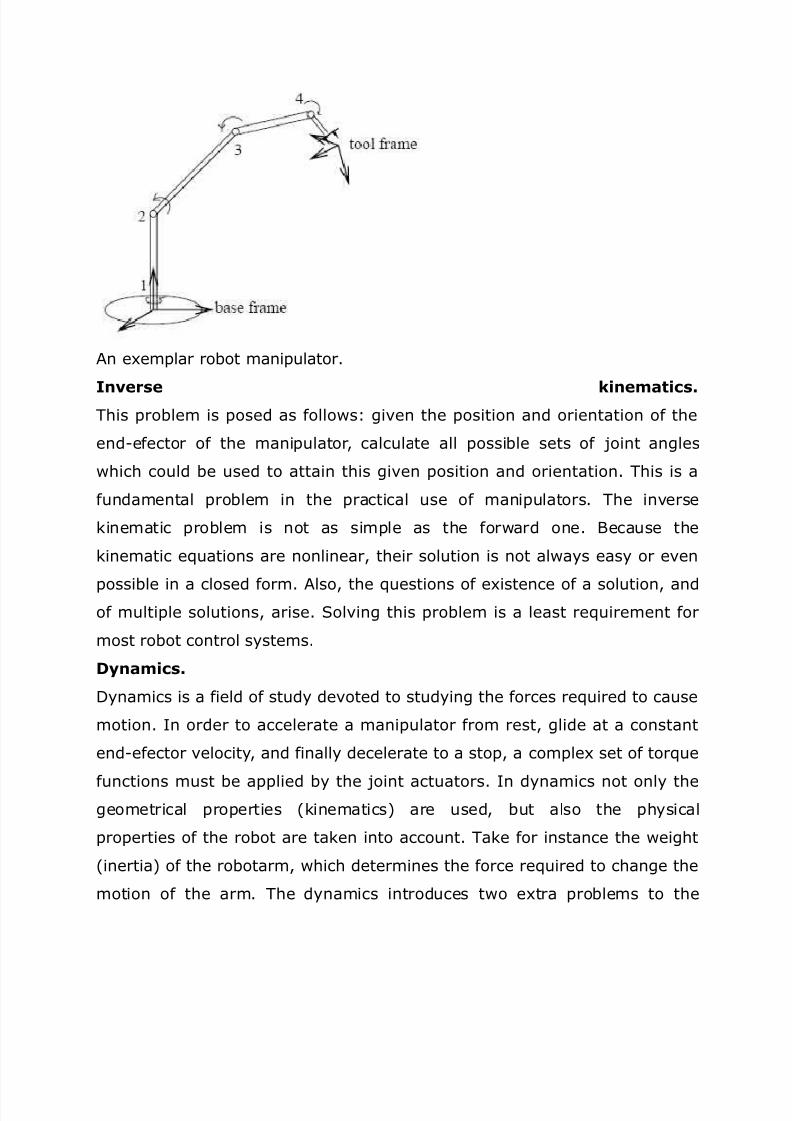
8/10/2019 unit ii NOTES New Microsoft Office Word 97 - 2003 Document (Autosaved).doc
http://slidepdf.com/reader/full/unit-ii-notes-new-microsoft-office-word-97-2003-document-autosaveddoc 41/56
n e(emplar robot manipulator.
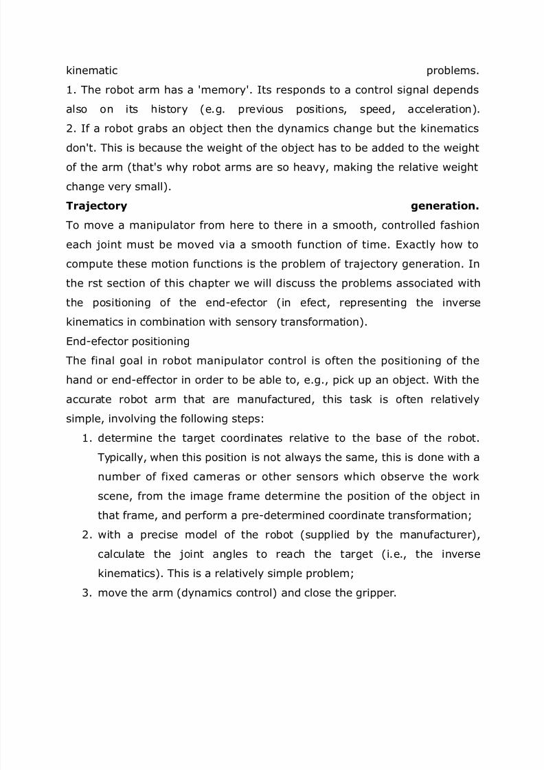
Inverse 6inematics%This problem is posed as follows gi$en the position and orientation of the
end-efector of the manipulator, calculate all possible sets of Doint angles
which could be used to attain this gi$en position and orientation. This is a
fundamental problem in the practical use of manipulators. The in$erse
kinematic problem is not as simple as the forward one. )ecause the
kinematic e&uations are nonlinear, their solution is not always easy or e$en
possible in a closed form. lso, the &uestions of e(istence of a solution, andof multiple solutions, arise. Sol$ing this problem is a least re&uirement for
most robot control systems.
#!namics%
'ynamics is a field of study de$oted to studying the forces re&uired to cause
motion. In order to accelerate a manipulator from rest, glide at a constant
end-efector $elocity, and finally decelerate to a stop, a comple( set of tor&ue
functions must be applied by the Doint actuators. In dynamics not only thegeometrical properties *kinematics+ are used, but also the physical
properties of the robot are taken into account. Take for instance the weight
*inertia+ of the robotarm, which determines the force re&uired to change the
motion of the arm. The dynamics introduces two e(tra problems to the
8/10/2019 unit ii NOTES New Microsoft Office Word 97 - 2003 Document (Autosaved).doc
http://slidepdf.com/reader/full/unit-ii-notes-new-microsoft-office-word-97-2003-document-autosaveddoc 42/56
kinematic problems.
1. The robot arm has a 4memory4. Its responds to a control signal depends
also on its history *e.g. pre$ious positions, speed, acceleration+.
<. If a robot grabs an obDect then the dynamics change but the kinematics
don4t. This is because the weight of the obDect has to be added to the weight
of the arm *that4s why robot arms are so hea$y, making the relati$e weight
change $ery small+.
Trajector! generation%
To mo$e a manipulator from here to there in a smooth, controlled fashion
each Doint must be mo$ed $ia a smooth function of time. 3(actly how to
compute these motion functions is the problem of traDectory generation. In
the rst section of this chapter we will discuss the problems associated with
the positioning of the end-efector *in efect, representing the in$erse
kinematics in combination with sensory transformation+.
3nd-efector positioning
The final goal in robot manipulator control is often the positioning of the
hand or end-effector in order to be able to, e.g., pick up an obDect. Aith the
accurate robot arm that are manufactured, this task is often relati$elysimple, in$ol$ing the following steps
1. determine the target coordinates relati$e to the base of the robot.
Typically, when this position is not always the same, this is done with a
number of fi(ed cameras or other sensors which obser$e the work
scene, from the image frame determine the position of the obDect in
that frame, and perform a pre-determined coordinate transformationE
<. with a precise model of the robot *supplied by the manufacturer+,calculate the Doint angles to reach the target *i.e., the in$erse
kinematics+. This is a relati$ely simple problemE
C. mo$e the arm *dynamics control+ and close the gripper.

8/10/2019 unit ii NOTES New Microsoft Office Word 97 - 2003 Document (Autosaved).doc
http://slidepdf.com/reader/full/unit-ii-notes-new-microsoft-office-word-97-2003-document-autosaveddoc 43/56
Involvement of neural networ6s. So if these parts are relati$ely simple
to sol$e with a high accuracy, why in$ol$e neural networksJ The reason is
the applicability of robots. Ahen 4traditional4 methods are used to control a
robot arm, accurate models of the sensors and manipulators *in some cases
with unknown parameters which ha$e to be estimated from the system4s
beha$iourE yet still with accurate models as starting point+ are re&uired and
the system must be calibrated. lso, systems which suffer from wear-and-
tear *and which mechanical systems don4tJ+ need fre&uent recalibration or
parameter determination. #inally, the de$elopment of more comple(
*adapti$eR+ control methods allows the design and use of more e(ible *i.e.,
less rigid+ robot systems, both on the sensory and motory side.
$%=%4rists
The kinematic structure of the robot arm allows to postion its end point at
any *(,y,9+ location in the C' space *. within the robot4s working space+
In order to pro$ide for the proper orientation of the hand"end-effector the
robot arm should ha$e a "rist . Typically a robot wrist pro$ides the same C'
rotations as a human hand roll, pitch, and yaw. wrist where the three
a(es of rotation intersect is called a spherical "rist . These ha$e thead$antage that the mathematical model used to calculate the wrist Doint
angles from their position and orientation in space is soluble.!ne problem in
achie$ing spherical wrist design is the physical difficulty of fitting all the
components into the a$ailable space. The si9e of the human wrist is small
because the muscles which power it are located in the forearm, not in the
wrist. Arist design is a comple( task, in$ol$ing conflicting goals. 'esirable
features of a wrist include - small si9e
- a(es close together to increase mechanical efficiency
- tool plate close to the a(es to increase strength and precision
- soluble mathematical model

8/10/2019 unit ii NOTES New Microsoft Office Word 97 - 2003 Document (Autosaved).doc
http://slidepdf.com/reader/full/unit-ii-notes-new-microsoft-office-word-97-2003-document-autosaveddoc 44/56
- no singularities in the work $olume
- back-dri$ing to allow programming by teach and playback
- decoupling between motions around the three a(es
- actuators mounted away from the wrist to allow si9e reduction
- paths for end effector control and power through the wrist
- power proportionate to the proposed task
- rugged housing.
lthough robots ha$e a certain amount of de(terity, it does not
compare to human de(terity. The mo$ements of the human hand are
controlled by C? muscles. #ifteen of these muscles are located in the

8/10/2019 unit ii NOTES New Microsoft Office Word 97 - 2003 Document (Autosaved).doc
http://slidepdf.com/reader/full/unit-ii-notes-new-microsoft-office-word-97-2003-document-autosaveddoc 45/56
forearm. The arrangement of muscles in the hand pro$ides great strength to
the fingers and thumb for grasping obDects. 3ach finger can act alone or
together with the thumb. This enables the hand to do many intricate and
delicate tasks. In addition, the human hand has <Q bones. *igure &->
shows the bones found in the hand and wrist. This bone, Doint, and muscle
arrangement gi$es the hand its de(terity.
Degrees of freedom (DOF) is a term used to describe a robots freedom
of motion in three dimensional spaceVspecifically, the ability to mo$e
forward and backward, up and down, and to the left and to the right. #or
each degree of freedom, a Doint is re&uired. robot re&uires si( degrees of
*igure &->% The arrangement of bones and Doints found in the human hand
pro$ides de(terity. 3ach Doint represents a degree of freedomE there are <<
Doints, and thus, << degrees of freedom in the human hand.
freedom to be completely $ersatile. Its mo$ements are clumsier than those

8/10/2019 unit ii NOTES New Microsoft Office Word 97 - 2003 Document (Autosaved).doc
http://slidepdf.com/reader/full/unit-ii-notes-new-microsoft-office-word-97-2003-document-autosaveddoc 46/56
of a human hand, which has << degrees of freedom. The number of degrees
of freedom defines the robots configuration. #or e(ample, many simple
applications re&uire mo$ement along three a(es W, X, and Y. See *igure &-
$?. These tasks re&uire three Doints, or three degrees of freedom. The three
degrees of freedom in the robot arm are the rotational tra$erse, the radial
tra$erse, and the $ertical tra$erse. The rotational traverse is mo$ement
on a $ertical a(is. This is the side-to-side swi$el of the robots arm on its
base. The radial traverse is the e(tension and retraction of the arm,
creating in-and-out motion relati$e to the base. The vertical traverse
pro$ides up-and-down motion.
#or applications that re&uire more freedom, additional degrees can be
obtained from the wrist, which gi$es the end effector its fle(ibility. The three
degrees of freedom in the wrist ha$e aeronautical names pitch, yaw, and
roll. See *igure &-$$. The pitch, or bend, is the up-and-down mo$ement of
the wrist. The yaw is the side-to-side mo$ement, and the roll , or swi$el,
in$ol$es rotation.

8/10/2019 unit ii NOTES New Microsoft Office Word 97 - 2003 Document (Autosaved).doc
http://slidepdf.com/reader/full/unit-ii-notes-new-microsoft-office-word-97-2003-document-autosaveddoc 47/56
robot re&uires a total of si( degrees of freedom to locate and orient its
hand at any point in its work en$elope, *igure &-$&. lthough si( degrees
of freedom are re&uired for ma(imum fle(ibility, most applications re&uire
only three to fi$e. Ahen more degrees of freedom are re&uired, the robotsmotions and controller design become more comple(. Some industrial robots
ha$e se$en or eight degrees of freedom. These additional degrees are
achie$ed by mounting the robot on a track or mo$ing base, as shown in
igure &-$;. The track-mounted robot shown in *igure &-$ has a total of
se$en degrees of freedom. This addition also increases the robots reach.
lthough the robots freedom of motion is limited in comparison with
that of a human, the range of mo$ement in each of its Doints is considerablygreater. #or e(ample, the human hand has a bending range of only about
1B? degrees. The illustrations in *igure &-$= show the si( maDor degrees of
freedom by comparing those of a robot to a person using a spray gun.

8/10/2019 unit ii NOTES New Microsoft Office Word 97 - 2003 Document (Autosaved).doc
http://slidepdf.com/reader/full/unit-ii-notes-new-microsoft-office-word-97-2003-document-autosaveddoc 48/56

8/10/2019 unit ii NOTES New Microsoft Office Word 97 - 2003 Document (Autosaved).doc
http://slidepdf.com/reader/full/unit-ii-notes-new-microsoft-office-word-97-2003-document-autosaveddoc 49/56
$%9%1obot end effector
In robotics, an end effector is the de$ice at the end of a robotic arm,
designed to interact with the en$ironment. The e(act nature of this de$ice
depends on the application of the robot.
In the strict definition, which originates from serial robotic manipulators, the
end effector means the last link *or end+ of the robot. t this endpoint the
tools are attached. In a wider sense, an end effector can be seen as the part
of a robot that interacts with the work en$ironment. This does not refer to
the wheels of a mobile robot or the feet of a humanoid robot which are also
not end effectorsVthey are part of the robot4s mobility.
3nd effectors may consist of a gripper or a tool. The gripper can be of two
fingers, three fingers or e$en fi$e fingers.
The end effectors that can be used as tools ser$es $arious purposes. Such
as, Spot welding in an assembly, spray painting where uniformity of painting
is necessary and for other purposes where the working conditions are
dangerous for human beings.
echanism of gripping
6enerally, the gripping mechanism is done by the grippers or mechanicalfingers. The number of fingers can be two, three or e$en as high as fi$e.
Though in the industrial robotics due to less complications, two finger
grippers are used. The fingers are also replaceable. 'ue to gradual wearing,
the fingers can be replaced without actually replacing the grippers. There are
two mechanisms of gripping the obDect in between the fingers *due to
simplicity in the two finger grippers, in the following e(planations, two finger
grippers are considered+.Shape of the gripping surface
The shape of the gripping surface on the fingers can be chosen according to
the shape of the obDects that are lifted by the grippers. #or e(ample, if the
robot is designated a task to lift a round obDect, the gripper surface shape

8/10/2019 unit ii NOTES New Microsoft Office Word 97 - 2003 Document (Autosaved).doc
http://slidepdf.com/reader/full/unit-ii-notes-new-microsoft-office-word-97-2003-document-autosaveddoc 50/56
can be a negati$e impression of the obDect to make the grip efficient, or for a
s&uare shape the surface can be plane.
Force required to grip the object
Though there are numerous forces acting o$er the body that has been lifted
by the robotic arm, the main force acting there is the frictional force. The
gripping surface can be made of a soft material with high coefficient of
friction so that the surface of the obDect is not damaged. The robotic gripper
must withstand not only the weight of the obDect but also acceleration and
the motion that is caused due to fre&uent mo$ement of the obDect. To find
out the force re&uired to grip the obDect, the following formula is used
# O Z$n
where
is the force re&uired to grip the obDect, is the coeffecient of friction, is the number of fingers in the gripper and is the weight of the obDect.
)ut the abo$e e&uation is incomplete. The direction of the mo$ement
also plays an important role o$er the gripping of the obDect. #or
e(ample, when the body is mo$ed upwards, against the gra$itational
force, the force re&uired will be more than towards the gra$itational
force. 5ence, another term is introduced and the formula becomes
# O Z$ng
5ere, the $alue of should not be taken as the acceleration due to
gra$ity. In fact, here stands for multiplication factor. The $alue of
ranges from 1 to C. Ahen the body is mo$ed in the hori9ontal
direction then the $alue is taken to be <, when mo$ed against the
gra$itational force then C and along the gra$itational force, i.e.,
downwards, 1.
The end effector of an assembly line robot would typically be a welding head,
or a paint spray gun. surgical robot4s end effector could be a scalpel or
others tools used in surgery. !ther possible end effectors are machine tools,

8/10/2019 unit ii NOTES New Microsoft Office Word 97 - 2003 Document (Autosaved).doc
http://slidepdf.com/reader/full/unit-ii-notes-new-microsoft-office-word-97-2003-document-autosaveddoc 51/56
like a drill or milling cutters. The end effector on the space shuttles robotic
arm uses a pattern of wires which close like the aperture of a camera around
a handle or other grasping point.
Ahen referring to robotic prehension there are four general categories of
robot grippers, these are[1\
1. Impacti$e ] Daws or claws which physically grasp by direct impact upon
the obDect.
<. Ingressi$e ] pins, needles or hackles which physically penetrate the
surface of the obDect *used in te(tile, carbon and glass fibre handling+.
C. stricti$e ] suction forces applied to the obDects surface *whether by
$acuum, magneto] or electroadhesion+.
;. %ontiguti$e ] re&uiring direct contact for adhesion to take place *such
as glue, surface tension or free9ing+.
1.Q.1obot gripperss of Artificial Gripper Mechanisms
6ripper echanisms can be classified into following maDor categories
1+ Mechanical finger @rippers- sub-classification is based on method of
actuation.
<+ 2acuum and Magnetic @rippers- sub-classification is based on type of
the force-e(erting elements.
C+ Universal @rippers- sub-classification is inflatable fingers, soft fingers 2
three fingered grippers.
Mechanical *inger @rippers
(in6age @rippers: there is no cam, screw, gear. There is mo$ement only
because of links attached to input and output. There must be perfect design
of mechanism such that input actuators motion is transformed into the
gripping action at the output.

8/10/2019 unit ii NOTES New Microsoft Office Word 97 - 2003 Document (Autosaved).doc
http://slidepdf.com/reader/full/unit-ii-notes-new-microsoft-office-word-97-2003-document-autosaveddoc 52/56
#ig 1 /inkage 6rippers
@ear and 1ac6 @rippers: mo$ement of input due to gear motion which
makes connecting links to go in motion to make gripping action at the output
link.
#ig C %am-actuated 6rippersb

8/10/2019 unit ii NOTES New Microsoft Office Word 97 - 2003 Document (Autosaved).doc
http://slidepdf.com/reader/full/unit-ii-notes-new-microsoft-office-word-97-2003-document-autosaveddoc 53/56
"am-actuated @rippers: reciprocating motion of the cam imparts motion
to the follower, thus causing fingers to produce a grabbing action. $ariety
of cam profiles can be employed
Screw-driven @rippers: operated by turning screw, in turn gi$ing motion
to connecting links and thus gi$ing griping motion to output. Screw motion
can be controlled by motor attached.
1ope +ulle! @rippers: motor attached to the pulley makes the winding
and unwinding motion of rope in turn it set gripper action into motion $ia
connecting link.
2acuum Magnetic @rippers
2acuum @rippers: for non-ferrous components with flat and smooth
surfaces, grippers can be built using standard $acuum cups or pads made of rubber-like materials. Not suitable for components with cur$ed surfaces or
with holes.

8/10/2019 unit ii NOTES New Microsoft Office Word 97 - 2003 Document (Autosaved).doc
http://slidepdf.com/reader/full/unit-ii-notes-new-microsoft-office-word-97-2003-document-autosaveddoc 54/56
Magnetic @ripper: used to grip ferrous materials. agnetic gripper uses amagnetic head to attract ferrous materials like steel plates. The magnetic
head is simply constructed with a ferromagnetic core and conducting coils.
2ersatile or universal @rippers
Inflatable grippers- used for picking up irregular and fragile obDects
without concentrated loading. In the initial position before gripping, the le$er
1, are opened up, the bellows are in a compressed condition because the gas
pressure in the bags,C, with the spheres is close, e$en a slight pressure of

8/10/2019 unit ii NOTES New Microsoft Office Word 97 - 2003 Document (Autosaved).doc
http://slidepdf.com/reader/full/unit-ii-notes-new-microsoft-office-word-97-2003-document-autosaveddoc 55/56
the obDect on a bag is sufficient enough to cause the bag wall to be deeply
depressed and surround the obDect. Ahen the degree of the surrounding is
ade&uate the le$er motion ceases, and pressure in the bags is reduced by
bellows, diaphragm de$ice pr $acuum pump, causing bags to harden without
changing shape and hence gripping the obDect. To release the obDect
operation is done in re$erse.
#ig = Inflatable 6rippers
Soft @rippers: consists of multi-links and a series of pulleys actuated by a
pair of wires. The soft gripper can acti$ely conform to the periphery of
obDects of any shape and hold them with uniform pressure.

8/10/2019 unit ii NOTES New Microsoft Office Word 97 - 2003 Document (Autosaved).doc
http://slidepdf.com/reader/full/unit-ii-notes-new-microsoft-office-word-97-2003-document-autosaveddoc 56/56
Three *ingered @rippers the clamping mo$ement of two-fingered type
normally e(ecutes *a+ beat mo$ement *b+ bite mo$ement *c+ parallel
mo$ement of the Daw. They are capable only of grasping or releasing
mo$ement.
![Arc therapy [autosaved] [autosaved]](https://static.documents.pub/doc/80x56/55a758ab1a28ab67458b4586/arc-therapy-autosaved-autosaved.jpg)
![TASAWWUR ISLAMI-Eksekutif ILIA [Autosaved] [Autosaved]](https://static.documents.pub/doc/80x56/55cf94c9550346f57ba46428/tasawwur-islami-eksekutif-ilia-autosaved-autosaved.jpg)


![Man of steel [autosaved] [autosaved]](https://static.documents.pub/doc/80x56/5551d154b4c905922b8b51a1/man-of-steel-autosaved-autosaved.jpg)
