
UNIVERSIT
ANALYZING TR
This report submitte
Malaysia Melaka (UT
(M
FACUL
ERSITI TEKNIKAL MALAYSIA ME
G TRANSFORMER MANUFACTURIN
BY USING FMEA APPROACH
bmitted in accordance with requirement of the Univ
ka (UTeM) for the Bachelor Degree of Manufactur
(Manufacturing Management) with Honours.
By
ZHARIF ANWAR BIN SULAIMAN
ACULTY OF MANUFACTURING ENGINEERIN
2011
IA MELAKA
URING FAILURE
e Universiti Teknikal
facturing Engineering
EERING
i
ABSTRACT
This report is focused on the failure analysis of the Tangent Delta failure in
transformer manufacturing process. Failure Mode and Effect Analysis or FMEA is a
one of the quality tools that able to guide the engineer or designer to overcome the
failure which has occurred in the product or in the manufacturing process. FMEA
helps managements to figure out the failures by determining potential of the failure
mode, effect of each failure, occurrences of each failure and the current control
process through Severity (S), Occurrences (O), and Detection (D) rankings. From the
combination of those rankings by using Risk Priority Number (RPN) technique, the
priority to reduce or eliminate (if possible) the failure can be executed by identifying
the highest RPN. For the FMEA effectiveness, other tools such as fish bone diagram,
Pareto chart and Why-Why Analysis will be used along with the FMEA experiment
which serves as communication tool and documentation for the FMEA Team.
Literature review provides the theories and facts which obtained from the journal and
books. That information will become an important reference in order to guide the
project achieves its main objective. Before executing this project, the methodology
need to be constructed regarding to the objectives and the problem stated. The
project flowchart indicates the process flow and serves as a guideline for the entire
project course. As well for the preparation for the next PSM II, the technique,
equipment and the required information also been defined to ensure the project is on
course and achieves its main objective. The case study is been concluded with the
study of the each process involved in the production line and also to strengthen the
information in order to provide better understanding. The experiment of the FMEA
analysis has reveals the possibilities from several factors which lead towards the
Tangent Delta failure. With proposed countermeasure based on the FMEA analysis,
the possibility to reducing the failure effect could be achieved if the correct actions
have been taken seriously.

ii
ABSTRAK
Laporan ini menjurus kepada analisa kegagalan terhadap kegagalan “Tangent Delta”
di dalam proses pembuatan transformer. “Failure Mode and Effect Analysis” atau
FMEA ialah salah satu kaedah kualiti yang mampu membimbing jurutera atau pereka
untuk mengatasi masalah kegagalan yang dihadapi pada sesetengah produk atau
proses pembuatan. FMEA membantu pengurusan untuk mengetahui kegagalan
dengan mengenal pasti mod potensi kegagalan, kesan setiap kegagalan, kehadiran
kegagalan dan proses kawalan melalui tahap “Severity (S)”, “Occurence (O)” dan
“Detection (D)”. Daripada kombinasi tahap tadi melalui teknik “Risk Production
Number” atau RPN, keutaamaan untuk megurangkan atau menghapuskan
(barangkali) kegagalan boleh dilaksanakan dengan mengenal tahap RPN yang
tertinggi. Untuk keberkesanan FMEA, kaedah yang lain turut digunakan seperti
“Pareto chart”, “Fishbone diagram” dan “Why-Why Analysis” bersama-sama analisa
ini. Ulasan terdahulu menyediakan teori dan fakta dimana telah didapati daripada
buku dan kertas kajian. Maklumat berkenaan akan menjadi rujukan penting dengan
harapan dapat membimbing projek ini mencapai objektif utamanya. Sebelum
melaksanakan projek ini, terdapat beberapa perkara perlu diambil kira. Carta alir
menunjukan cara kerja dan menjadi rujukan untuk keseluruhan projek ini. Kajian kes
telah dijalankan melalui kajian terhadap proses yang terlibat didalam barisan
pengeluaran. Ia juga untuk menguatkan maklumat awal dengan tujuan member
pengetahuan yang jelas. Eksperimen FMEA telah mendedahkan kebarangkalian
kegagalan daripada beberapa faktor. Dengan mencadangkan beberapa langkah
pembaikan berdasarkan analisa, kebarangkalian untuk mengurangkan kesan
kegagalan boleh dicapai jika langkah diambil adalah betul dan tepat.

iii
ACKNOWLEDGEMENTS
First of all, thanks to Allah for HIS guidance and blessing, I am able to complete the
final year project. I wish to express my gratitude to all those people whose has given me
their support during this project.
I would like to express my token of appreciation to Tn Hj Abd Rahman Mahmood who
responsible to become my project supervisor for his guidance, advice, encouragement,
and support throughout the project.
Special thanks to every staff in ABC Company especially to all staff under Production
Department, Quality Assurance Department and Test Department because every one of
them was particularly helpful.
I would like to thanks to all my friends for all their support and help. I am not being able
to get through the entire difficult situation and face the pressure well without their help
and support. Thank you.
Finally to my family, thank you so much for all your tremendous support to ensure that I
complete my project.
May Allah S.W.T bless all of us. Amin.
iv
TABLE OF CONTENT
Abstract i
Abstrak ii
Acknowledgement iii
Table of Content iv
List of Tables viii
List of Figures x
List Abbreviations xiii
1. INTRODUCTION 1
1.1 Problem Statement 3
1.2 Objective 4
1.3 Importance of the Study 4
1.4 Scope of the Study 4
2. LITERATURE REVIEW 6
2.1 Failure Mode and Effect Analysis (FMEA) 7
2.1.1 Purpose of FMEA 7
2.1.2 Benefits of FMEA 8
2.1.3 Part of a Comprehensive Quality System 9
2.1.4 FMEA Standards 10
2.1.5 FMEA Planning 10
2.1.6 The FMEA Team 12
2.1.7 Design FMEA vs. Process FMEA 13
2.1.8 FMEA Scope 14
2.1.9 Input, Outputs and Other Quality Tools Related 15
2.1.10 FMEA Process 16
2.1.11 FMEA Worksheet 25
2.1.12 Ten Steps for the FMEA 29

v
2.2. Transformer Manufacturing 36
2.2.1 Electrical Transformer 36
3. METHODOLOGY 39
3.1 Project Planning 40
3.2 Project Flowchart Activities 43
3.2.1 Conforming the PSM Title 43
3.2.2 Project Details Discussion 43
3.2.3 Literature Review 44
3.2.4 Methodology Construction 44
3.2.5 Gathering Input 44
3.2.6 Brainstorming Session 45
3.2.7 FMEA Process 46
3.2.8 Result 47
3.2.9 Recommend the Corrective Actions 47
3.2.10 Modification 47
3.2.11 FMEA Output 47
3.2.12 Completing Report & Submission 48
3.3 FMEA Process 48
3.4. Technique Used 50
4. CASE STUDY 52
4.1 Product 53
4.1.1 Product Specification 53
4.2 Process Flow 54
4.2.1 Power Transformer Manufacturing Process 54
4.2.2 Production Process Section 54
4.2.3 Production Workflow 56
4.2.4 Core Building Section 56
4.2.5 Winding Section 58
4.2.6 Mechanical and Electrical Assembly Section 60

vi
4.2.6 Finishing Section 72
4.2.7 Insulation Section 78
4.3. Input Material and Output Product 79
4.4. Equipment and Manufacturing Process 82
4.5. Case Study Findings 85
4.5.1 Using 4M Technique 86
5. RESULT AND ANALYSIS 95
5.1 Fish Bone Diagram 95
5.2 Possibilities Explanations 96
5.3. Why-Why Analysis 100
5.4 FMEA Procedure 103
5.4.1 Determining the potential, causes likelihood
and current control process 103
5.4.2 Determining the severity, occurrence and detection 107
5.4.3 Constructing FMEA Experiment 109
5.4.4 Pareto Charts 111
5.5 Result Analysis 114
5.6 Action Recommended 116
5.6.1 Improving Detection 116
5.6.2 Reducing Occurrence 119
5.6.3 Reducing Severity 122
5.6.4 Possible new severity, occurrence and detection rankings 125
5.7 Revised RPN 126
5.7.1 RPN Comparison 128
5.7.2 Percentage of Reduced RPN 130
5.8 Purposed Countermeasure 132
vii
6. CONCLUSION AND RECOMMENDATIONS 134
REFERENCES 136
APPENDICES
A Gantt chart for PSM 1
B Gantt chart for PSM 2
C Power Transformer general drawing
viii
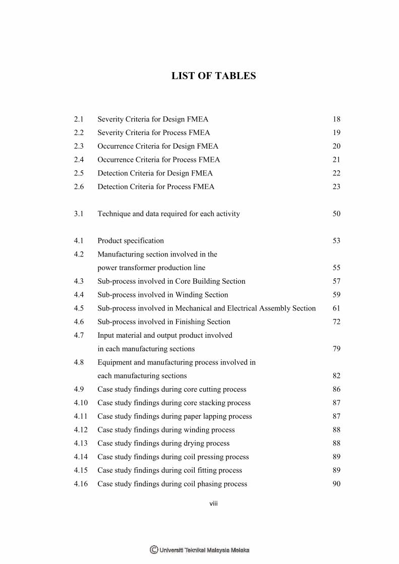
LIST OF TABLES
2.1 Severity Criteria for Design FMEA 18
2.2 Severity Criteria for Process FMEA 19
2.3 Occurrence Criteria for Design FMEA 20
2.4 Occurrence Criteria for Process FMEA 21
2.5 Detection Criteria for Design FMEA 22
2.6 Detection Criteria for Process FMEA 23
3.1 Technique and data required for each activity 50
4.1 Product specification 53
4.2 Manufacturing section involved in the
power transformer production line 55
4.3 Sub-process involved in Core Building Section 57
4.4 Sub-process involved in Winding Section 59
4.5 Sub-process involved in Mechanical and Electrical Assembly Section 61
4.6 Sub-process involved in Finishing Section 72
4.7 Input material and output product involved
in each manufacturing sections 79
4.8 Equipment and manufacturing process involved in
each manufacturing sections 82
4.9 Case study findings during core cutting process 86
4.10 Case study findings during core stacking process 87
4.11 Case study findings during paper lapping process 87
4.12 Case study findings during winding process 88
4.13 Case study findings during drying process 88
4.14 Case study findings during coil pressing process 89
4.15 Case study findings during coil fitting process 89
4.16 Case study findings during coil phasing process 90

ix
4.17 Case study findings during top-yoke assembly process 90
4.18 Case study findings during electrical jointing and wiring process 91
4.19 Case study findings during pre-heating process 91
4.20 Case study findings during tap changer assembly process 92
4.21 Case study findings during pre-tank preparation process 92
4.22 Case study findings during tanking process 93
4.23 Case study findings during oil filling and purifying process 93
4.24 Case study findings during In-house machining process 94
5.1 Material factors with further explanation 97
5.2 Machine factors with further explanation 98
5.3 Method factors with further explanation 99
5.4 Man factors with further explanation 99
5.5 Determining potential failure modes for each factors 104
5.6 Determining causes for each factors 105
5.7 Determining the current control process for each factors 106
5.8 Determining severity rankings at each factors 107
5.9 Determining Occurrence rankings at each factors 108
5.10 Determining Detection rankings at each factors 109
5.11 FMEA table 110
5.12 Detection improvement 117
5.13 Reducing Occurrence 120
5.14 Reducing Severity 123
5.15 The new RPN generated with new possible severity, occurrence
and detection rankings 125
5.16 Comparison between benchmarked RPN and revised RPN 128
5.17 Reduction percentage 130
5.18 Purposed countermeasures for each factor based on benchmarked RPN 133

x
LIST OF FIGURES
1.1 Power Transformer 3
1.2 Power transformer 30 MVA (33/11 KV) in operation. 5
2.1 Example of Start-up worksheet 25
2.2 Example of Design FMEA scope worksheet 26
2.3 Example of Process FMEA scope worksheet 27
2.4 Example of Design FMEA worksheet 28
2.5 The simple illustration of electrical transformer 36
2.6 The completed windings and the copper wire without insulation 37
2.7 The transformer core 38
2.8 The tank preparation and the oil filling 38
3.1 The project flowchart 41
3.2 The FMEA Process 42
4.1 Transformer unit, 30MVA-203 (33/11KV) 53
4.2 Production process flow 56
4.3 Core plate 57
4.4 Core Structure 57
4.5 Core Building flow chart 58
4.6 Paper lapping process 59
4.7 Winding process 59
4.8 Winding flow chart 60
4.9 Mechanical and Electrical Assembly Section general flow chart 62
4.10 Drying process flow chart 63
4.11 Drying oven 63
4.12 Coil pressing process flow chart 64
4.13 Illustration of coil winding which been press down by base plate 64
xi
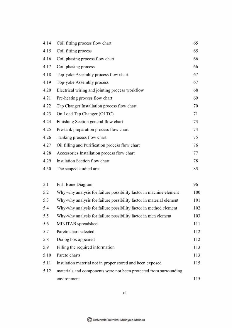
4.14 Coil fitting process flow chart 65
4.15 Coil fitting process 65
4.16 Coil phasing process flow chart 66
4.17 Coil phasing process 66
4.18 Top-yoke Assembly process flow chart 67
4.19 Top-yoke Assembly process 67
4.20 Electrical wiring and jointing process workflow 68
4.21 Pre-heating process flow chart 69
4.22 Tap Changer Installation process flow chart 70
4.23 On Load Tap Changer (OLTC) 71
4.24 Finishing Section general flow chart 73
4.25 Pre-tank preparation process flow chart 74
4.26 Tanking process flow chart 75
4.27 Oil filling and Purification process flow chart 76
4.28 Accessories Installation process flow chart 77
4.29 Insulation Section flow chart 78
4.30 The scoped studied area 85
5.1 Fish Bone Diagram 96
5.2 Why-why analysis for failure possibility factor in machine element 100
5.3 Why-why analysis for failure possibility factor in material element 101
5.4 Why-why analysis for failure possibility factor in method element 102
5.5 Why-why analysis for failure possibility factor in men element 103
5.6 MINITAB spreadsheet 111
5.7 Pareto chart selected 112
5.8 Dialog box appeared 112
5.9 Filling the required information 113
5.10 Pareto charts 113
5.11 Insulation material not in proper stored and been exposed 115
5.12 materials and components were not been protected from surrounding
environment 115
xii
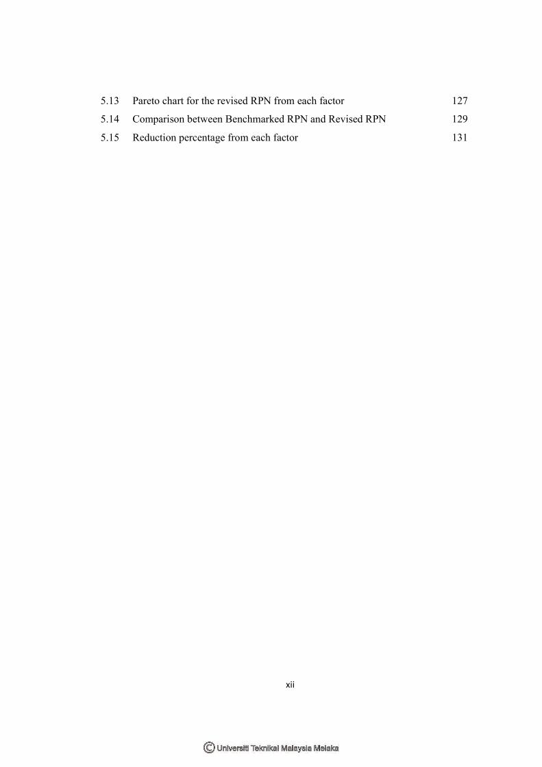
5.13 Pareto chart for the revised RPN from each factor 127
5.14 Comparison between Benchmarked RPN and Revised RPN 129
5.15 Reduction percentage from each factor 131
xiii
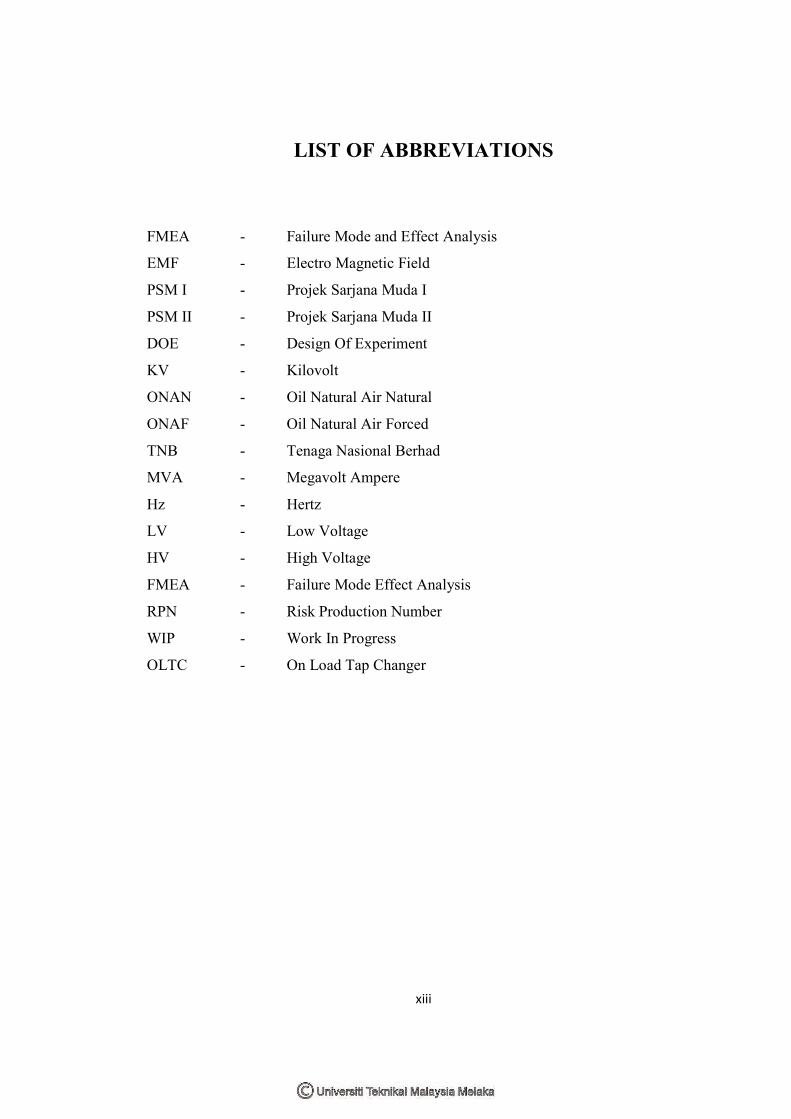
LIST OF ABBREVIATIONS
FMEA - Failure Mode and Effect Analysis
EMF - Electro Magnetic Field
PSM I - Projek Sarjana Muda I
PSM II - Projek Sarjana Muda II
DOE - Design Of Experiment
KV - Kilovolt
ONAN - Oil Natural Air Natural
ONAF - Oil Natural Air Forced
TNB - Tenaga Nasional Berhad
MVA - Megavolt Ampere
Hz - Hertz
LV - Low Voltage
HV - High Voltage
FMEA - Failure Mode Effect Analysis
RPN - Risk Production Number
WIP - Work In Progress
OLTC - On Load Tap Changer
1
CHAPTER 1
INTRODUCTION
During this section, this chapter will explain about the background, problem
statement, objective, scope and importance of study. Furthermore this chapter also
briefly explains about the Failure Mode and Effect Analysis (FMEA) that will be
applying at the manufacturing or assembly processes for this final year project.
The production output is the most vital elements in the manufacturing industries.
This is why, the output or product reflects about the assembly operation and the
design of the product itself. When talk about the quality and reliability, when a
product or system fails to achieve its final objective (functionality), it will trigger a
disaster to the manufacturer which produce it. Customer complaints, critics, and
turnovers will be a price that had to pay with costly recall and rework from the
manufacturer. Many manufacturers are empowered themselves to gain loyalty from
their customers. Absolutely the quality, functionality and reliability will be the key
for their core strategy. Ensuring to achieve the objective, the manufacturer needs to
concern about the product design and also the manufacturing process operations
which important to the output that will produce.
The defects or failure of the products or sometimes in the manufacturing operations
can contribute product or system fail to achieve its main objective, to perform
functionality exactly as the manufacturer expectation. The effects of the defects or
failure of the product can contribute a huge significant in terms of quality, reliability,
functionality and another important addition, safety. This is because, the failure,
defects, and errors where occurred to the product or manufacturing assemblies
operation (related to the product), can bring a problem to the manufacturer in terms

2
of losses, delays, increased manufacturing costs, or any drawbacks which can
jeopardize their business.
Failure Mode Effect and Analysis or FMEA was becoming the powerful answer about the
problems of reliability and failure analysis. FMEA is defined as “a systematic group of
activities to; (a) recognize and evaluate the potential failure of a product / process
and the effects of that failure, (b) identify actions that could eliminate or reduce the
chance of the occurrence of potential failure”. Failure modes can be described as the
modes of failures of a part or sub-assembly while the effect indicates the effect of the
failure of a part in any of the modes, on a system. FMEA is popular tool or technique
to identify failures of parts or components, which have significant consequences on
the system when it will use. Any failures related with the modes may affect the
system performance and also the quality of the system itself.
FMEA is useful for studying the failure modes, failure causes and their effects on the
system as well as taking appropriate preventive actions. It is a reliability evaluation /
design technique where it provides basic information to reliability prediction and
product & process design. The information was come from the examination or
research of the potential failure mode and effects through a product or system.
FMEA helps the engineers and designers to detect any potential problems which
contributing to the failure in the product or system in the early stages such as design
stage or simulation stage. From this stage it will ensure them to avoid any changes or
reworks at later stage such like production / manufacturing stage or product warranty
stage where it claims the higher price when performing it (Teng and Ho, 1996)
FMEA is becoming the selected method for this final year project, Analyzing
transformer failure by using FMEA approach. This is because; the FMEA providing
the detailed failure analysis and also detailed information and those data can be used
as conclusion and solution for the particular failure. Another advantage is, the data
itself could be used again if any improvement is been implemented.
1.1. Problem State
“Tangent Delta” (Tan
manufacturing. “Tange
transformer unit excee
20°C. Tan δ is also kn
for electrical propertie
diagnostic test to det
electrical machines and
customer due to inten
electrical failure of the
3
Statement
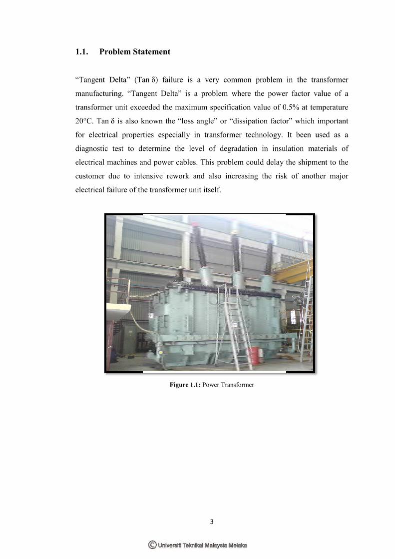
(Tan δ) failure is a very common problem in
“Tangent Delta” is a problem where the power
exceeded the maximum specification value of 0.5
lso known the “loss angle” or “dissipation factor”
operties especially in transformer technology. It
to determine the level of degradation in insula
es and power cables. This problem could delay th
intensive rework and also increasing the risk
of the transformer unit itself.
Figure 1.1: Power Transformer
lem in the transformer
ower factor value of a
of 0.5% at temperature
factor” which important
gy. It been used as a
insulation materials of
elay the shipment to the
risk of another major
4
1.2. Objective
1. To determine the possible factors that lead “Tangent Delta” problem by
applying with Fish Bone Diagram method.
2. To analyze the problem by using FMEA technique.
3. To analyze the identified possible factors by using Pareto chart and revise
RPN technique.
4. To propose a countermeasure with a purpose solution.
1.3. Importance Of The Study
The importance of this study is to investigate and determine the possible factors of
the problems which contribute to the failure of the transformer and to analyze the
failure by using FMEA technique. From the data collected from the study can be use
to propose the new solution or answer to countermeasure the particular problem and
defects.
1.4. Scope Of The Study
The study and the observation will be conducted at the ABC Company plant at Ulu
Kelang, Kuala Lumpur. ABC Company is one of the transformer manufacturers in
the ASEAN region which been established in early 1980s. The scope of this final
year project will be focus only at the entire manufacturing process of the electrical
transformer.

The research of this f
analyzing it by using
method such as Caus
process flowchart and
technique.
The subject for this stu
information of this pow
the country. This tran
ABC Company and
manufacturing stage.
Figure 1
5
this final year project study is focus on the sta
using FMEA technique. To meet this propose
Cause-and-Effect diagram (fish bone diagrams),
rt and other necessary method will be use to su
his study is the power transformer unit (step down t
is power transformer unit is 30MVA (33/11 KV) a
transformer type is among the highest product
and also always obtaining “Tangent Delta”
gure 1.2: Power transformer 30 MVA (33/11 KV) in operati
the stated problem and
oposed research, other
rams), Pareto diagram,
to support the FMEA
down type). The general
KV) and widely used in
roduction output in the
Delta” failure during
peration.
6
CHAPTER 2
LITERATURE REVIEW
This chapter provides a basic knowledge and information about the Failure Mode
and Effect Analysis (FMEA) where it been selected as a primary study for this final
year project. The FMEA will be described with the necessary element required,
benefit & limitation, and other relevant knowledge related to the FMEA and also to
the project. This chapter also will describe another relevant topic in order to provide
a deep understanding about the study in order to strengthen the purposed project.
Without the guidelines from it, it will impossible to conduct the particular study and
if so, the project will result the meaningless outcomes.

7
2.1. Failure Mode and Effect Analysis (FMEA)
Failure Mode and Effects Analysis or FMEA is a common methodology used by
engineer or designer for analyzing the potential reliability problems in early
development stage where it were easier to take appropriate actions to overcome these
selective issues, thereby enhancing the reliability. FMEA is a proactive tool
developed to identify, evaluate and prevent product and/or process failures
(Bluvband and Grabov, 2009)
FMEA also is a decision making tool for prioritizing corrective action to enhance
product or system performance by eliminating or reducing failure rate (Chang and
Sun, 2009). Until now, FMEA has been recognized as a powerful tool used to
identify critical components / parts / functions whose failure will lead to undesirable
outcomes such as production loss, production rework, injury or even an accident
(Sharma et al. 2007). Previously, this tool was first proposed by NASA in 1963 for
their obvious reliability requirements. Since then, it has been intensively used as a
powerful technique for system safety and reliability analysis of product and
processes in a wide range of industries such as aerospace, nuclear, automotive and
medical (Ebeling, 2001)
2.1.1. Purpose of FMEA
The main purposed of FMEA is to identify the possible failure modes that could
occur in the design or manufacturing of a product and determining the impact of
those failures. (Bluvband and Grabov, 2009). Thus the corrective action can be taken
in order to reduce or eliminate the potential for failures to occur. An effective FMEA
identifies corrective actions required to prevent failures from reaching the customer
and to assure the highest possible yield, quality and reliability.
There are several types of FMEA that has been implemented in the industries.
Although the process steps is relatively same but they are some differences regarding
to its subject that been research. The types of FMEA are:

8
a) System - focus on global system functions
b) Design - focuses on components and subsystems
c) Process - focuses on manufacturing and assembly processes
d) Service - focuses on service functions
e) Software - focuses on software functions
FMEA also documents current knowledge and actions about the risks of failures, for
use in continuous improvement. FMEA is used during design to prevent failures.
Later it’s used for control, before and during ongoing operation of the process. The
information used in the FMEA process should come from the company’s own
production lines, the customers, and the field data of similar products (Teng and Ho,
1996). Ideally, FMEA begins during the earliest conceptual stages of design and
continues throughout the life of the product or service.
2.1.2. Benefits of FMEA
The FMEA programme offers a wide range of benefit for the organization which
implemented it. Main benefits of implementing FMEA are improving the product or
process quality and reliability and satisfying the customers (Teng and Ho, 1996). The
several benefits that can be described are:
a) Minimizes late changes and associated cost since FMEA is been carried out
during design stage.
b) Identifies failure modes which will have significant impact
c) Identifies the causes of failures and minimizes them
d) Helps in redesigning to reduce the effect of failures
e) Improve product reliability, maintainability and availability of the system
f) Increases customer satisfaction
g) Prioritize product / process deficiencies for improvement
h) Emphasizes problem prevention
i) Providing information of:
i. Maintainability analysis

9
ii. Safety analysis
iii. Survivability
iv. Vulnerability
v. Logistic support analysis
vi. Maintenance plan analysis
vii. Risk analysis
viii. Failure detection
ix. Failure isolation
2.1.3. Part of a Comprehensive Quality System
A formal FMEA process should be a part of comprehensive quality system. This is
why, a standalone FMEA process could be effective but the company will not get a
maximum benefit without other system to support conducting FMEAs and
implementing improvements that are result of the FMEAs. The example of from this
statement such as one element of comprehensive quality system is effective use of
data and information. Without reliable product or process data, the FMEA becomes a
guessing game based on opinions rather than actual facts. This factor could lead the
FMEA team focused on the wrong failure modes, thus missing significant
opportunities to improve the failure modes that are the biggest problems.
2.1.4. FMEA Standards
For the stand alone FMEAs, the primary standards were been used are the “military
standard” (Mil-Std 1629A) and the “Society of Automotive Engineers standard”
(SAE J1739). These standards are only limited for the design and process FMEAs.
These standards provide general FMEA forms and documents, identify criteria for
the quantification of risk associated with potential failures, and provide very general
guidelines on the mechanic of completing FMEAs.

10
Since the FMEA can be used as a part of the comprehensive quality system, it is been
subjected under the quality standards of ISO/TS 16949. This standard is created for
the automotive industry and based on ISO 9000 and builds on QS 9000, which was
originally developed by the Chrysler, Ford, and General Motors (GM) Supplier
Quality Requirement Task Force. The objective was to develop a fundamental
quality system that provides for continuous improvement, emphasizing defect
prevention and the reduction of waste in the supply chain. Furthermore ISO/TS
16949 incorporates the process approach to the quality system requirements
originally presented in QS 9000
2.1.5. FMEA Planning
Before planning the FMEA steps on process, there are several series of
considerations that have to be view. The following statement below will be regards
as a minimum consideration.
2.1.5.1 Selecting appropriate applications for the analysis
The FMEA may be authorized by individuals at various levels in the organization or
may be required by ISO 9000, QS 9000, Six Sigma methodologies, internal quality
programs or customer requirements. However, the FMEA is expensive to complete
and should be completed only in those instances where the benefit outweigh the cost.
2.1.5.2 Identifying and allocating resources
The resources will includes FMEA team members and reporting structure, physical
space to conduct the analysis and store to documentation, time, and clerical or
communications support.


