

1
10 June 2009
UPGRADE OF CLEANROOM 212 AND GOWN ROOM 211 CLINTON COMMUNITY COLLEGE – PLATTSBURGH, NY
The following document describes the work required to upgrade existing rooms 212 and 211 to ISO Class 6 and 7 (Class 1000 and 10,000) Clean rooms. The main room 212 will be ISO Class 6 and the gown room 211 will be ISO Class 7. Required new performance: Room Number 212 Class ISO 6 (Class 1000) Air Exchange Rate: 150 air changes per hour +/- Recirculation air flow: 1500 CFM Room pressure: 0.10 in w.g. positive Room Temperature: 70 F +/-2 Room Humidity 50% +/- 10 % summer Minimum winter Humidity: 30% Process exhaust from existing BL2/3 Hoods 740 CFM Room Number 211 Class ISO 7 (Class 10000) Air Exchange Rate: 75 air changes per hour +/- Recirculation air flow: 375 CFM Room pressure: 0.05 in w.g. positive Room Temperature: 70 F +/-2 Room Humidity 50% +/- 10 % summer Minimum winter Humidity: 30% Basic description of work involved: Create new soffit wall above existing BL2/3 hoods Create partition wall between Laminar flow hood N-48 and existing wall Provide and install one vertical DX air handling unit behind the new partition wall Provide and install one air cooled condensing with compressor in 3rd floor Mechanical space – Location to be determined. Make necessary cut outs to facilitate refrigerant piping runs between A/C condensing unit and DX air handling unit. Heat of rejection will be into the third floor mechanical room
2
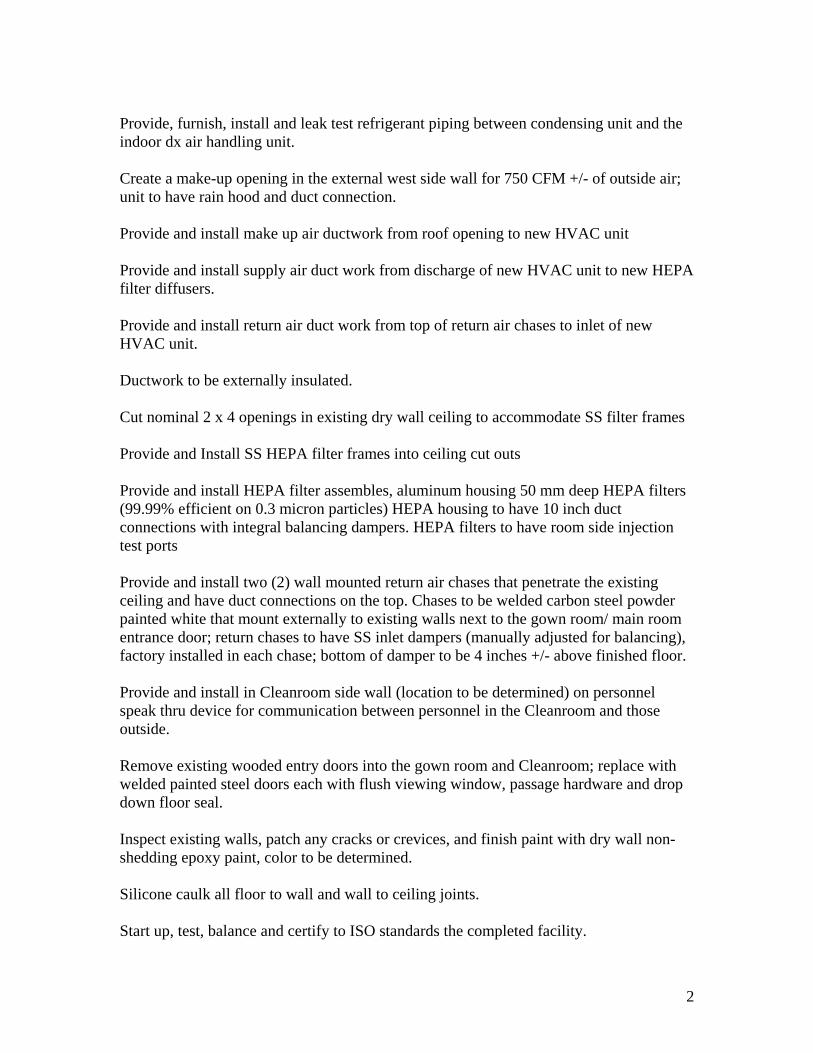
Provide, furnish, install and leak test refrigerant piping between condensing unit and the indoor dx air handling unit. Create a make-up opening in the external west side wall for 750 CFM +/- of outside air; unit to have rain hood and duct connection. Provide and install make up air ductwork from roof opening to new HVAC unit Provide and install supply air duct work from discharge of new HVAC unit to new HEPA filter diffusers. Provide and install return air duct work from top of return air chases to inlet of new HVAC unit. Ductwork to be externally insulated. Cut nominal 2 x 4 openings in existing dry wall ceiling to accommodate SS filter frames Provide and Install SS HEPA filter frames into ceiling cut outs Provide and install HEPA filter assembles, aluminum housing 50 mm deep HEPA filters (99.99% efficient on 0.3 micron particles) HEPA housing to have 10 inch duct connections with integral balancing dampers. HEPA filters to have room side injection test ports Provide and install two (2) wall mounted return air chases that penetrate the existing ceiling and have duct connections on the top. Chases to be welded carbon steel powder painted white that mount externally to existing walls next to the gown room/ main room entrance door; return chases to have SS inlet dampers (manually adjusted for balancing), factory installed in each chase; bottom of damper to be 4 inches +/- above finished floor. Provide and install in Cleanroom side wall (location to be determined) on personnel speak thru device for communication between personnel in the Cleanroom and those outside. Remove existing wooded entry doors into the gown room and Cleanroom; replace with welded painted steel doors each with flush viewing window, passage hardware and drop down floor seal. Inspect existing walls, patch any cracks or crevices, and finish paint with dry wall non-shedding epoxy paint, color to be determined. Silicone caulk all floor to wall and wall to ceiling joints. Start up, test, balance and certify to ISO standards the completed facility.
3
ALL INTERESTED PARTIES SHALL CONDUCT A SITE WALK THRU PRIOR TO OFFERING A PROPOSAL. PLEASE SEE THE ATTACHED SUPPLEMENTARY TECHNICAL INFORMATON AND SPECIFICATIONS FOR FURTHER INFORMATION

Clinton Community Collegs- Plattsburgh, NY
Concept sketch 9 March 2009
Air Flow Diagram and HVAC Calculations
Air Flow Schematic 790 Cfm From Out doors (Worst Case) Summer 86dB/70wB
Winter -13 F 0 Humidity
HVAC Unit1875 CFM
740 CFM BL2/3 1085 Cfm Exhaust 375
1500 725 Cfm 360 Cfm
1500 CFM 375 Cmn
Main Room Gown RoomClass 1000 (Iso 6) Class 10,0000.10 " w.g. Pos (Iso 7)70 F +/2 F /50% rH +/-10% 0.05 " w.g. Pos.
70 F +/-2 F rH 50% +/-10%
35 Cfm 15 CfmPress. Air Press. Air
Hepa(s) Hepa(s)

Internal Room Sensible Loads
Item Main Rm Gown Rm TotalTransmission 4150 1610 5760Lights 700 600 1300People 400 400 800process 3400 0 3400
Total 11260
Room Design Point 70 F / 50% rH
Selected SA Temperature based on having 45F water available 50 Deg Sat
Cfm required to offset Room Senible Load is RSH/((1.09*(70-50))
CFM required 516.5138
This is less than that required to offset exhaust - Hence unit will always over cool and require constant reheat
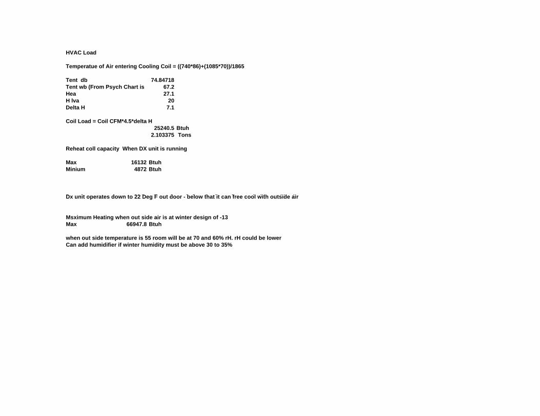
HVAC Load
Temperatue of Air entering Cooling Coil = ((740*86)+(1085*70))/1865
Tent db 74.84718Tent wb (From Psych Chart is 67.2Hea 27.1H lva 20Delta H 7.1
Coil Load = Coil CFM*4.5*delta H25240.5 Btuh
2.103375 Tons
Reheat coll capacity When DX unit is running
Max 16132 BtuhMinium 4872 Btuh
D it t d t 22 D F t d b l th t it f l ith t id iDx unit operates down to 22 Deg F out door - below that it can free cool with outside air
Msximum Heating when out side air is at winter design of -13Max 66947.8 Btuh
when out side temperature is 55 room will be at 70 and 60% rH. rH could be lower Can add humidifier if winter humidity must be above 30 to 35%

Air Handling Unit Schematic
MXB w/ DX Coil Hot DD Fan w/ DD Fan w/Outside Air Pre- Coil Water VFD VFD To Room
Filters Coil with Access Panes To Room
Bldg Hot WaterReturn Air
TTo andFrom DxCond.Unit
E ti t d H t t i d b d 120 F S l / 100 R tEstimated Hot water required based on 120 F Supply / 100 Return
Item GPM
Main coil winter operation 7
SIZE REV
SCALESHEET OF
DRAWN
CHECKED
QA
MFG
APPROVED
SBB Inc
1 2
D
6500 New Venture Gear DrE. Syracuse, NY 13057
315-437-6500www.sbbinc.com
SBB Inc 6/8/2009
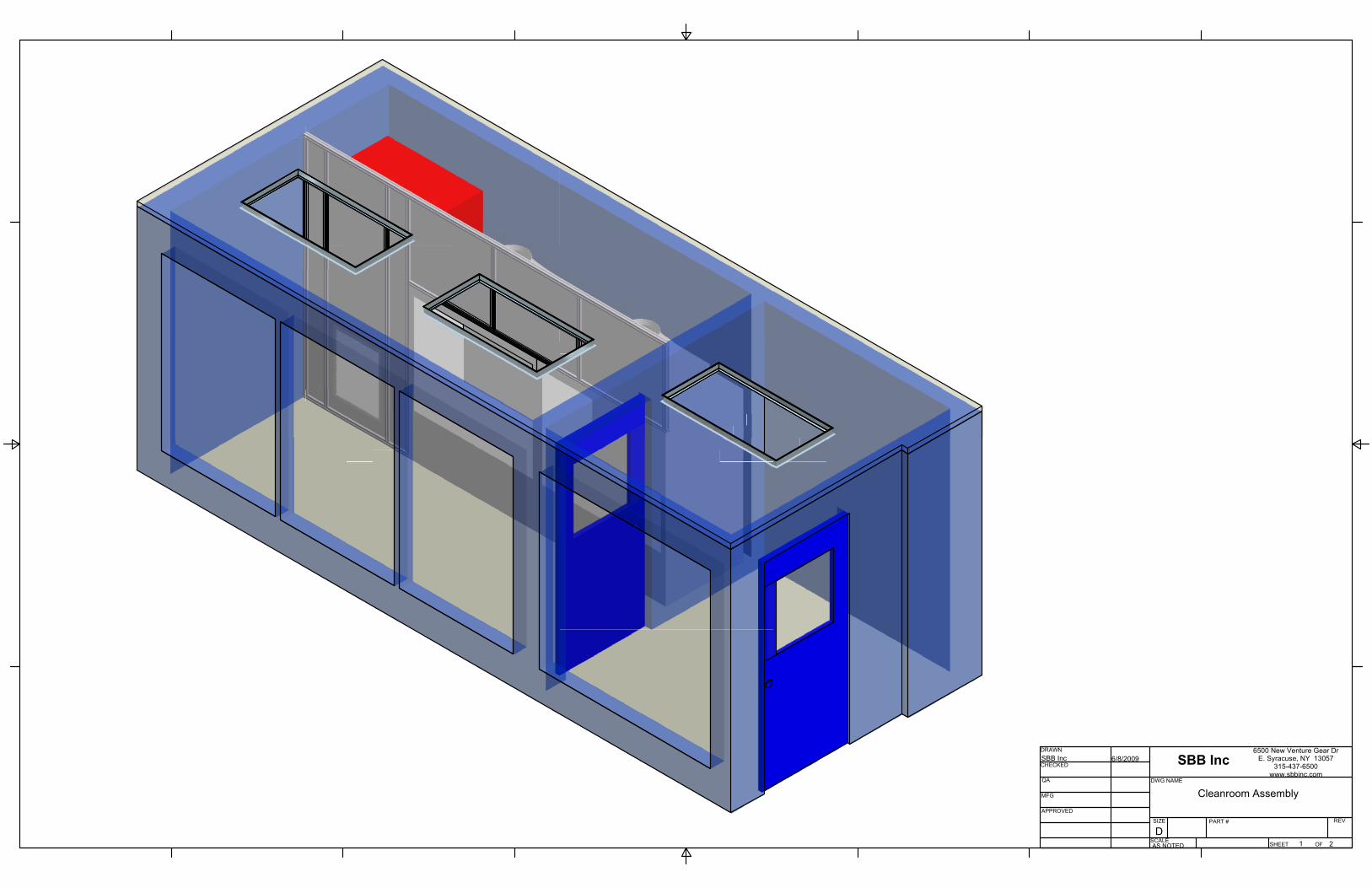
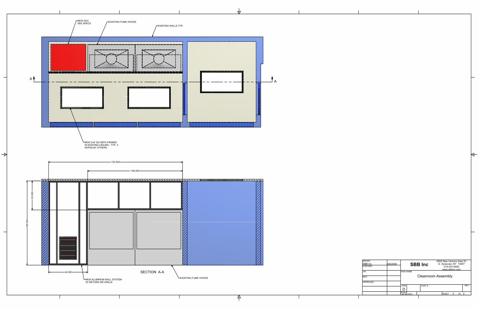
Cleanroom Assembly
AS NOTED
DWG NAME
PART #
SECTION A-A
SIZE REV
SCALESHEET OF
DRAWN
CHECKED
QA
MFG
APPROVED
SBB Inc
2 2
D
6500 New Venture Gear DrE. Syracuse, NY 13057
315-437-6500www.sbbinc.com
SBB Inc 6/8/2009
Cleanroom Assembly
AS NOTED
DWG NAME
PART #
AA
NEW 2'x4' SS HEPA FRAMESIN EXISTING CEILING - TYP. 3HEPAS BY OTHERS
NEW AHUSEE SPECS EXISTING FUME HOODS
EXISTING WALLS TYP.
NEW ALUMINUM WALL SYSTEMW/ RETURN AIR GRILLE
EXISTING FUME HOODS
96.0
00
44.500
33.0
00
152.500
108.000
SECTION A-A
SECTION A-A
1
1
2
2
3
3
4
4
A A
B B
C C
D D
SIZE REV
SCALESHEET OF
DRAWN
CHECKED
QA
MFG
APPROVED
SBB Inc
1 1
C
6500 New Venture Gear Dr.E. Syracuse, NY 13057
315-437-6500www.sbbinc.com
V Bongio 5/12/2008
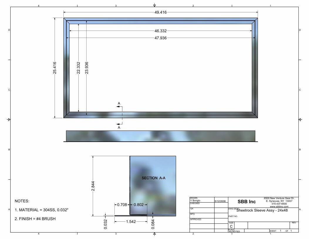
Sheetrock Sleeve Assy - 24x48
AS NOTED
DWG DESC.
PART NO.
A
A
0.03
2
2.84
4
0.708 0.802
1.542
0.08
4
49.416
25.4
16
22.3
32
23.9
36
46.332
47.936
NOTES: 1. MATERIAL = 304SS, 0.032" 2. FINISH = #4 BRUSH
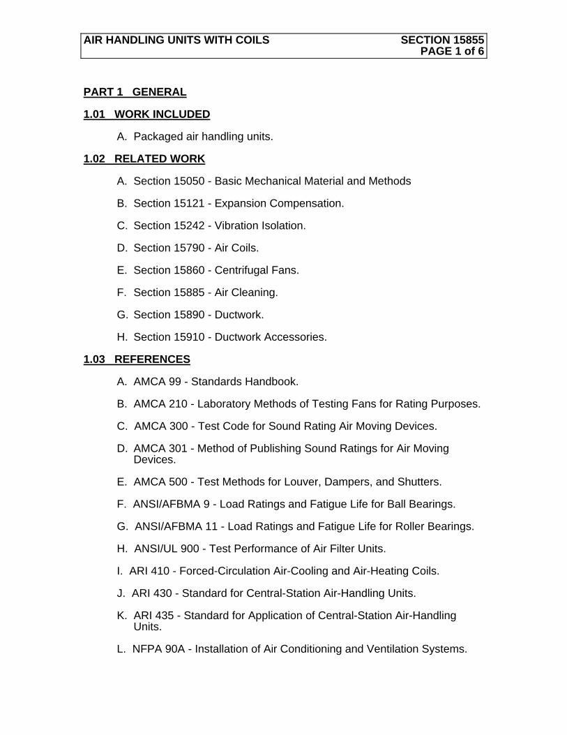
AIR HANDLING UNITS WITH COILS SECTION 15855 PAGE 1 of 6
PART 1 GENERAL 1.01 WORK INCLUDED A. Packaged air handling units. 1.02 RELATED WORK A. Section 15050 - Basic Mechanical Material and Methods B. Section 15121 - Expansion Compensation. C. Section 15242 - Vibration Isolation. D. Section 15790 - Air Coils. E. Section 15860 - Centrifugal Fans. F. Section 15885 - Air Cleaning. G. Section 15890 - Ductwork. H. Section 15910 - Ductwork Accessories. 1.03 REFERENCES A. AMCA 99 - Standards Handbook. B. AMCA 210 - Laboratory Methods of Testing Fans for Rating Purposes. C. AMCA 300 - Test Code for Sound Rating Air Moving Devices. D. AMCA 301 - Method of Publishing Sound Ratings for Air Moving
Devices. E. AMCA 500 - Test Methods for Louver, Dampers, and Shutters. F. ANSI/AFBMA 9 - Load Ratings and Fatigue Life for Ball Bearings. G. ANSI/AFBMA 11 - Load Ratings and Fatigue Life for Roller Bearings. H. ANSI/UL 900 - Test Performance of Air Filter Units. I. ARI 410 - Forced-Circulation Air-Cooling and Air-Heating Coils. J. ARI 430 - Standard for Central-Station Air-Handling Units. K. ARI 435 - Standard for Application of Central-Station Air-Handling
Units. L. NFPA 90A - Installation of Air Conditioning and Ventilation Systems.
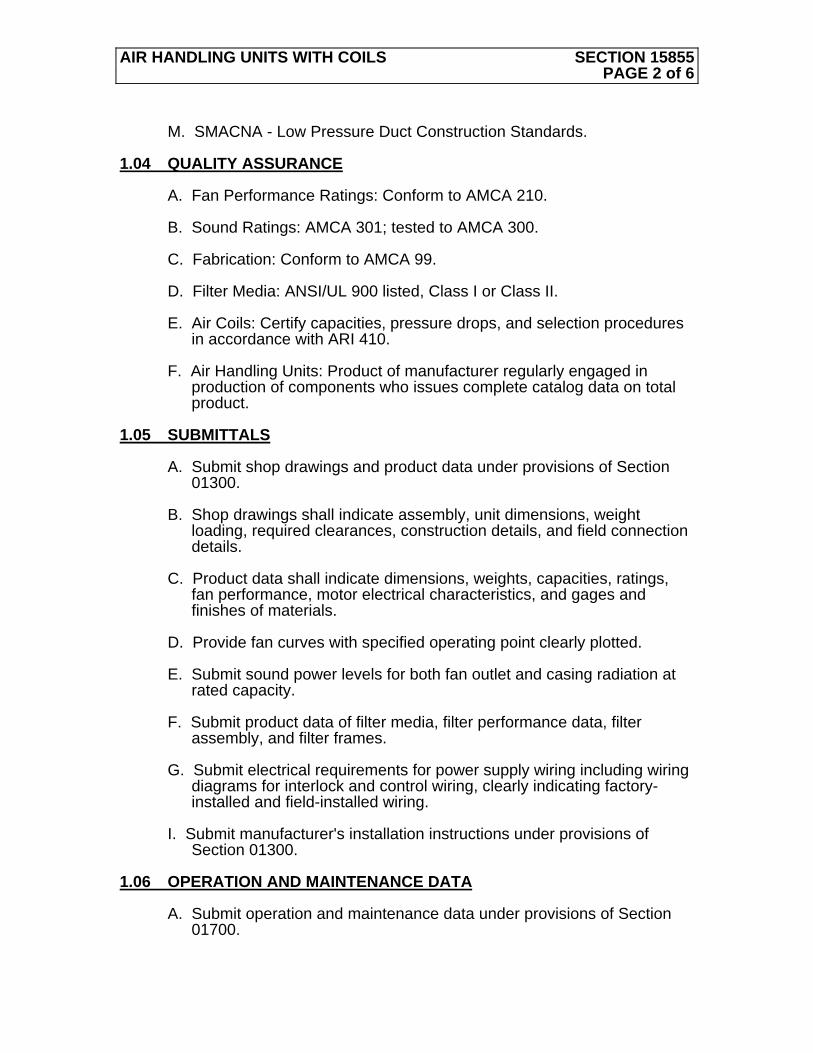
AIR HANDLING UNITS WITH COILS SECTION 15855 PAGE 2 of 6
M. SMACNA - Low Pressure Duct Construction Standards. 1.04 QUALITY ASSURANCE A. Fan Performance Ratings: Conform to AMCA 210. B. Sound Ratings: AMCA 301; tested to AMCA 300. C. Fabrication: Conform to AMCA 99. D. Filter Media: ANSI/UL 900 listed, Class I or Class II. E. Air Coils: Certify capacities, pressure drops, and selection procedures
in accordance with ARI 410. F. Air Handling Units: Product of manufacturer regularly engaged in
production of components who issues complete catalog data on total product.
1.05 SUBMITTALS A. Submit shop drawings and product data under provisions of Section
01300. B. Shop drawings shall indicate assembly, unit dimensions, weight
loading, required clearances, construction details, and field connection details.
C. Product data shall indicate dimensions, weights, capacities, ratings,
fan performance, motor electrical characteristics, and gages and finishes of materials.
D. Provide fan curves with specified operating point clearly plotted. E. Submit sound power levels for both fan outlet and casing radiation at
rated capacity. F. Submit product data of filter media, filter performance data, filter
assembly, and filter frames. G. Submit electrical requirements for power supply wiring including wiring
diagrams for interlock and control wiring, clearly indicating factory-installed and field-installed wiring.
I. Submit manufacturer's installation instructions under provisions of
Section 01300. 1.06 OPERATION AND MAINTENANCE DATA A. Submit operation and maintenance data under provisions of Section
01700.
AIR HANDLING UNITS WITH COILS SECTION 15855 PAGE 3 of 6
B. Include instructions for lubrication, filter replacement, motor and drive replacement, spare parts lists, and wiring diagrams.
1.07 DELIVERY, STORAGE, AND HANDLING A. Deliver products to site under provisions of Section 01600 in factory-
fabricated protective containers, with factory-installed shipping skids and lifting lugs.
B. Store and protect products under provisions of Section 01600. C. Store in clean dry place and protect from weather and construction
traffic. Handle carefully to avoid damage to components, enclosures, and finish.
1.08 ENVIRONMENTAL REQUIREMENTS A. Do not operate units for any purpose, temporary or permanent, until
ductwork is clean, filters are in place, bearings lubricated, and fan has been test run under observation.
1.09 EXTRA STOCK A. Provide one set of disposable panel filters under provisions of Section
01700. PART 2 PRODUCTS 2.01 MANUFACTURERS
A. SBB Inc., 6500 New Venture Gear Dr. E. Syracuse, NY 13057 (315-4437 6500) http://www.sbbinc.com OR EQUAL.
2.02 GENERAL A. Fabricate draw-thru type air handling units suitable for medium
pressure operation. B. Fabricate units with fan and cooling coil section plus accessories,
including mixing box section, filter section. C. Factory fabricate and test air handling units of sizes, capacities, and
configuration as indicated and specified. D. Base performance on sea level conditions. 2.03 CASING

AIR HANDLING UNITS WITH COILS SECTION 15855 PAGE 4 of 6
A. Construct of heavy gage aluminum frame work with insulated aluminum panels / doors. Unit to be vertically configured. Drain pan shall be 14 gage 304SS, with 304SS ¾” drain line extended to external side of cabinet. Stubs are to be capped for shipment. Condensate traps are furnished and installed by others external of the air handler cabinet.
B. Insulate casing sections with 1-1/2 (minimum) inch (40 mm) thick, 3 lbs
per cu ft (96 kg per cu m) density glass fiber insulation, "K" value at 75 degrees F (42 degrees C) maximum 0.26 Btu/inch/sq ft/degrees F/hr (0.037 W/m/degree K), applied to internal surfaces with adhesive. Silicone seal all exposed edges of insulation. Insulation and adhesive: Conform to NFPA 90A. ALL insulation is to be clad internally with minimum 16 gage epoxy powder coated steel sheets.
C. Construct drain pans from stainless steel with welded corners. Cross
break and pitch to drain connection. Provide drain pans under cooling coil section.
D. Provide structure to brace casings for suction pressure of 2.5 inch wg
negative (or fan design TSP negative, whichever is greater) with respect to ambient, with maximum deflection of 1 in 200.
2.04 FANS A. Provide fan section with direct drive airfoil plug fan. B. Provide self-aligning, grease lubricated, ball or roller bearings designed
as sealed for life and with 100,000 hour minimum life rating. C. Mount fan and motor internally on welded steel base coated with
powder coat epoxy finish. Factory mount motor direct drive plug fan wheel to motor and balance to 0.023”/sec. Provide access to motor, bearings, and fan wheel through hinged access doors. Hinges shall be stainless steel to eliminate paint chipping and particulate transfer to supply duct system. Mount base on vibration isolators; refer to Section 15242.
2.05 MOTORS AND DRIVES A. Motors:. Fan/motor system shall be designed for use at direct coupled
synchronous speed of motor at nominal 900, 1200, 1800 rpm. Please see data sheet.
B. Bearings: ANSI/AFBMA 9, L-50 life at 100,000 hours, heavy duty pillow
block type, self-aligning, grease-lubricated, sealed for life, ball bearings.
C. Shafts: Solid hot rolled steel, ground and polished, with key-way, and
protectively coated with lubricating oil.

AIR HANDLING UNITS WITH COILS SECTION 15855 PAGE 5 of 6
D. Direct drive system shall be used unless otherwise specified on drawings and mechanical schedules) Integral VFD compatible with motor shall be factory mounted and wired to unit external disconnect/ junction box
2.06 COILS A. Provide coil section with coils and access to both sides of coils.
Enclose coils with headers and return bends fully contained within casing. Slide coils into casing through removable end panel with blank off sheets and sealing collars at connection penetrations.
B. Provide stainless steel drain pans for cooling coil. C. Cooling coil is direct refrigerant cooled with 3/8 inch copper tubes and aluminum fins. Please see data sheet for performance D. A hot water reheat coil shall be integral to the unit to provide reheat And room temperature control whenever room loads are below design
2.07 SPRAYED COIL DEHUMIDIFIER Not Used 2.08 HUMIDIFIER A unit mounted ultra sonic humidifier shall be provided to maintain
minimum 30% room humidty during winter operation 2.09 FILTERS A. Provide pre filter frame within the unit housing with filter guides, access
doors from both sides, for side loading. B. PREFILTERS: Provide high capacity arrangement with 2 inch (50 mm)
deep disposable panel filters. Filters to have minimum 30% dust spot efficiency. Refer to Section 15885.
E. Provide filter pressure drop indicator gauges across bank of filters, one
piece dial face 0.1” minimum divisions with full scale rated at minimum 2x’s fully loaded filters, with static pressure tips.
PART 3 EXECUTION 3.01 INSTALLATION A. Install in accordance with manufacturer's instructions.

AIR HANDLING UNITS WITH COILS SECTION 15855 PAGE 6 of 6
B. Install unit on vibration isolators. Refer to Section 15242.
END OF SECTION

SECTION A-A
SECTION A-A
1
1
2
2
3
3
4
4
A A
B B
C C
D D
SIZE REV
SCALESHEET OF
DRAWN
CHECKED
QA
MFG
APPROVED
SBB Inc
1 1
C
6500 New Venture Gear Dr.E. Syracuse, NY 13057
315-437-6500www.sbbinc.com
V Bongio 5/12/2008
Sheetrock Sleeve Assy - 24x48
AS NOTED
DWG DESC.
PART NO.
A
A
0.03
2
2.84
4
0.708 0.802
1.542
0.08
4
49.416
25.4
16
22.3
32
23.9
36
46.332
47.936
NOTES: 1. MATERIAL = 304SS, 0.032" 2. FINISH = #4 BRUSH


