

Master thesis in Software Engineering and Management
REPORT NO. 2008:016
ISSN: 1651-4769
Department of Applied Information Technology
Using ADO.NET Entity Framework in Domain-Driven Design: A Pattern Approach
ANDREY YEMELYANOV
IT University of Göteborg
Chalmers University of Technology and University of Gothenburg
Göteborg, Sweden 2008

I
Using ADO.NET Entity Framework in Domain-Driven Design: A Pattern Approach
ANDREY YEMELYANOV
© ANDREY YEMELYANOV, 2008
Report no. 2008:016
ISSN: 1651-4769
Department of Applied Information Technology
IT University of Göteborg
Chalmers University of Technology and University of Gothenburg
P O Box 8718
SE – 402 75 Göteborg
Sweden
Telephone +46 (0) 31-772 4895

II
Using ADO.NET Entity Framework in Domain-Driven Design: A Pattern Approach
ANDREY YEMELYANOV
Department of Applied Information Technology
IT University of Göteborg
Chalmers University of Technology and University of Gothenburg
Supervisor: Miroslaw Staron
ABSTRACT
In the object community domain-driven design philosophy has recently gained prominence. The
application of domain-driven design practices in iterative software development projects promises to
conquer complexity inherent in building software. And with the reduced complexity comes more
intimate understanding of a problem domain, which results in better software, capable of effectively
addressing user needs and concerns. The ADO.NET Entity Framework with its emphasis on modeling
conceptual business entities and handling persistence can potentially facilitate domain-driven design.
However, it is not clear exactly how the framework should be used in the context of domain-driven
development. This exploratory case study was commissioned by Volvo Information Technology (Volvo
IT) and it sought to provide guidance on using the Entity Framework in domain-driven design at the
company. The study produced a number of important results. Firstly, a total of 15 guidelines were
proposed for adopting the framework at Volvo IT. These guidelines address such issues as domain
modeling during requirements engineering, efficient mapping among various models, reverse-
engineering of legacy databases, and a number of others. Secondly, six critical factors (performance,
abstraction, competence, features, simplicity and support for multiple data sources) were identified that
must be considered in adopting the Entity Framework in domain-driven design at the company. Finally,
based on one of these factors, performance evaluation of the framework’s querying mechanisms was
performed, which further strengthened the guidelines.
Keywords
Domain-driven design, ADO.NET Entity Framework, persistence, domain model, patterns, object-
relational impedance mismatch.

III
ACKNOWLEDGEMENTS
This Master thesis has been a great exercise in knowledge discovery which would have been impossible
without:
The Swedish Institute, whose kind support in cultural and monetary aspects has kept me going
throughout my whole stay in Sweden. I would like to thank the Swedish Institute for granting me a
scholarship to pursue my studies at the IT University.
Miroslaw Staron – Software Engineering and Management program manager at the IT University, who
was an academic supervisor of mine. Miroslaw provided valuable guidance on tackling the study most
effectively. I would like to thank him for his patience, understanding and, most importantly, objective
criticism of my work.
Ludwik Wallin – an architect at Volvo Information Technology, who was an industrial supervisor of
mine. Ludwik provided a valuable insight into the issues concerning building enterprise software and
also guided me towards relevant aspects of the Entity Framework and domain-driven design that need be
carefully studied. I would also like to thank all the employees from the Software Process Improvement
group and other departments at Volvo IT who contributed to this study with important interviews and
informal discussions.
Thanks again to all of you for your help, time and willingness to share experience and insightful
comments!
Andrey Yemelyanov
May 17, 2008
Gothenburg, Sweden.
IV
TABLE OF CONTENTS
1. INTRODUCTION................................................................................................................. 1
2. CASE STUDY DESIGN ....................................................................................................... 3
2.1 Context and Subjects ...................................................................................................... 3
2.2 Study Subjects................................................................................................................. 3
2.3 Data Collection and Analysis.......................................................................................... 3
2.4 Study Execution .............................................................................................................. 3
2.5 Threats to Validity .......................................................................................................... 4
3. RELATED WORK ............................................................................................................... 4
4. THEORETICAL FRAMEWORK ...................................................................................... 5
4.1 Structuring domain logic................................................................................................. 5
4.1.1 Procedural style (Transaction Script)..................................................................... 6
4.1.2 Domain Model style ................................................................................................ 7
4.2 Domain-driven design..................................................................................................... 7
4.2.1 The building blocks of domain-driven design ......................................................... 8
4.2.1.1 Layered architecture............................................................................................ 8
4.2.1.2 Entities ................................................................................................................ 8
4.2.1.3 Services ............................................................................................................... 8
4.2.1.4 Aggregates .......................................................................................................... 9
4.2.1.5 Factories.............................................................................................................. 9
4.2.1.6 Repository ........................................................................................................... 9
4.3 The ADO.NET Entity Framework.................................................................................. 9
4.3.1 The building blocks of the Entity Framework......................................................... 9
4.3.1.1 The Entity Data Model...................................................................................... 10
4.3.1.2 Entity client ....................................................................................................... 10
4.3.1.3 Entity SQL ........................................................................................................ 10
4.3.1.4 Object Services ................................................................................................. 10
4.3.1.5 LINQ to Entities................................................................................................ 10
4.3.2 Accessing data via the Entity Framework and SQL Client................................... 11
4.3.3 Concluding remarks.............................................................................................. 12
5. ADOPTING THE ENTITY FRAMEWORK
IN DOMAIN-DRIVEN DESIGN: MAIN REQUIREMENTS .............................................. 12
5.1 Main goals..................................................................................................................... 12
5.2 Main requirements ........................................................................................................ 13
V
5.3 The role of the guidelines requirements........................................................................ 13
6. ENTITY FRAMEWORK IN DOMAIN-DRIVEN
DESIGN: CRUCIAL FACTORS .............................................................................................. 13
6.1 Interviews...................................................................................................................... 13
6.2 Factors........................................................................................................................... 13
6.3 Data retrieval performance............................................................................................ 14
6.4 Support for higher-level abstractions............................................................................ 14
6.5 In-house competence level in objects, databases and object-relational mismatch........ 15
6.6 Rich feature set ............................................................................................................. 15
6.7 Simplicity...................................................................................................................... 15
6.8 Support for heterogeneous data sources for the domain model .................................... 15
6.9 Concluding remarks ...................................................................................................... 15
7. QUERY PERFORMANCE EVALUATION.................................................................... 16
7.1 SqlDataReader .............................................................................................................. 17
7.2 NHibernate .................................................................................................................... 17
7.3 Entity Framework ......................................................................................................... 17
7.3.1 Entity SQL ............................................................................................................. 18
7.3.2 LINQ to Entities .................................................................................................... 18
7.3.3 Compiled LINQ to Entities ................................................................................... 18
7.4 Analysis......................................................................................................................... 18
8. ENTITY FRAMEWORK GUIDELINES………………………………………………..19
8.1 Pattern discovery process.............................................................................................. 20
8.2 Core guidelines ............................................................................................................. 20
8.2.1 Guideline 1: Business domain modeling............................................................... 20
8.2.2 Guideline 2: Capturing domain logic ................................................................... 20
8.2.3 Guideline 3: Expressing domain model in software ............................................. 20
8.2.4 Guideline 4: Validating the domain model ........................................................... 21
8.2.5 Guideline 5: Applying the Aggregate pattern ....................................................... 21
8.2.6 Guideline 6: Applying the Repository pattern ...................................................... 21
8.2.7 Guideline 7: Reverse engineering......................................................................... 21
8.2.8 Guideline 8: Implementing business rules in the Entity Framework.................... 21
8.3 Mapping patterns………………………………………………………………………21
8.3.1 Pattern: Object Association .................................................................................. 21
8.3.2 Pattern: Object Aggregation................................................................................. 21
8.3.3 Pattern: Object Composition ................................................................................ 21

VI
8.3.4 Pattern: Object Self-Association........................................................................... 21
8.3.5 Pattern: Object Inheritance .................................................................................. 22
8.3.6 Pattern: Domain Object........................................................................................ 22
8.3.7 Pattern: Advanced Mapper ................................................................................... 22
8.3.8 Mapping pattern example ..................................................................................... 23
9. DISCUSSION ...................................................................................................................... 23
9.1 Why patterns? ............................................................................................................... 23
9.2 Initial evaluation ........................................................................................................... 23
10. CONCLUSION ................................................................................................................... 24
10.1 Key findings.................................................................................................................. 24
10.2 Future research.............................................................................................................. 24
11. ACKNOWLEDGMENTS .................................................................................................. 25
12. REFERENCES.................................................................................................................... 25
LIST OF FIGURES
Figure 1: Part of a banking application built in a procedural style………………………………...6
Figure 2: Transitioning from procedural database-driven
design to domain-driven design……………………………………………………………………7
Figure 3: A navigation map of the language of domain-driven design.............................................8
Figure 4: Layered architecture according to DDD…………………………………………………8
Figure 5: Aggregate…………………………………………...........................................................9
Figure 6: Entity Framework architecture………………………………………………………….10
Figure 7: Order application relational schema…………………………………………………….11
Figure 8: Data access with the SQL Client..………………………………………………………11
Figure 9: Conceptual Entity Data Model built
on top of the relational database schema in the order application..……………………………….12
Figure 10: Data access with LINQ in the Entity Framework...……………………………………12
Figure 11: Domain aggregate retrieved from the relational database……………………………..16
Figure 12: Relational model underlying the Blog Aggregate……………………………………..16
Figure 13: SQL query to retrieve the Blog aggregate………… …………………… …………..16
Figure 14: SQL Client............................................................... .....................................................17
Figure 15: hSQL in NHibernate……………………………… …………………………… …..17
Figure 16: The Entity Data Model generated from the Blog relational model……………………18
Figure 17: Compiled LINQ to Entities query…………………………………………………......18

VII
Figure 18: A comparative evaluation of query performance
with DataReader, NHibernate and the Entity Framework……………………………………....19
Figure 19: Taxonomy of the Entity Framework Guidelines………………………………….....20
Figure 20: Object association……………………………………………………………………21
Figure 21: Object aggregation…………………………………………………………………...21
Figure 22: Object composition…………………………………………………………………..21
Figure 23: Object self-association……………………………………………………………….22
Figure 24: Table-Per-Hierarchy inheritance mapping…………………………………………...22
Figure 25: Table-Per-Concrete-Class inheritance mapping…………………………………......22
Figure 26: Table-Per-Class inheritance mapping………………………………………………..22
Figure 27: Multiple association………………………………………………………………….22
Figure 28: Mapping to relational model…………………………………………………………22
LIST OF APPENDICES
Appendix A: Interview questions..................................................................................................27
Appendix B: C# code to retrieve the Blog aggregate with the SQL client…....…………………29
Appendix C: Example domain model based on domain-driven design principles.......................31

1
Using ADO.NET Entity Framework in Domain-Driven Design: A Pattern Approach
Andrey Yemelyanov IT University of Göteborg
ABSTRACT In the object community domain-driven design philosophy has
recently gained prominence. The application of domain-driven
design practices in iterative software development projects
promises to conquer complexity inherent in building software.
And with the reduced complexity comes more intimate
understanding of a problem domain, which results in better
software, capable of effectively addressing user needs and
concerns. The ADO.NET Entity Framework with its emphasis on
modeling conceptual business entities and handling persistence
can potentially facilitate domain-driven design. However, it is not
clear exactly how the framework should be used in the context of
domain-driven development. This exploratory case study was
commissioned by Volvo Information Technology (Volvo IT) and
it sought to provide guidance on using the Entity Framework in
domain-driven design at the company. The study produced a
number of important results. Firstly, a total of 15 guidelines were
proposed for adopting the framework at Volvo IT. These
guidelines address such issues as domain modeling during
requirements engineering, efficient mapping among various
models, reverse-engineering of legacy databases, and a number of
others. Secondly, six critical factors (performance, abstraction,
competence, features, simplicity and support for multiple data
sources) were identified that must be considered in adopting the
Entity Framework in domain-driven design at the company.
Finally, based on one of these factors, performance evaluation of
the framework’s querying mechanisms was performed, which
further strengthened the guidelines.
Keywords Domain-driven design, ADO.NET Entity Framework, persistence,
domain model, patterns, object-relational impedance mismatch.
1. INTRODUCTION In a use-case driven software development process [3, 8, 14, 39]
use cases serve as a primary artifact for establishing system
requirements, validating system architecture, testing and
communicating with domain experts and other project
stakeholders [13]. Such a process is often used alongside with the
Unified Modeling Language (UML) [8]. After the use case
specification is fed into further development stages, two major
artifacts are conceived: analysis model and design model. There is
an interesting dichotomy between the two models in that they
address two distinct dimensions (problem and solution) of the
same given domain. The analysis model represents the product of
analyzing a problem domain to organize its concepts. What role
these concepts will play in software is not important in that
context [22]. It specifies what problem needs to be solved. The
major content of the analysis model includes collaborations in the
UML and analysis classes [19]. The design model, on the other
hand, specifies how the given problem is to be solved. Crain [19]
refers to this model as a platform-specific model because it
captures “a mixture of behavior and technology”. For example,
the design model may include a JDBC 1class to specify how the
lifecycle of persistent business objects is handled.
Such a seeming redundancy in models is necessary in order to
ensure a smooth transition from a problem space (use case
specifications and analysis model) to a solution space (design and
implementation models), which is not trivial. Evans [22] argues
that once the implementation begins, analysis and design models
grow increasingly disjoint. This happens because the analysis
model is created with no design issues in mind. Mixing
implementation concerns into analysis models is considered bad
practice and is, therefore, highly discouraged. As a result, the pure
analysis model proves impractical for design purposes and is
abandoned as soon as programming begins [22]. There is a danger
to such practice, Evans [22] continues. While analysis models
may accurately capture business needs and incorporate valuable
knowledge about the problem domain, there is no guarantee that
the design model will successfully rediscover the insights gained
during analysis. Eventually, as the gap between the models
widens, it becomes progressively difficult to feed insights from
analysis into design.
Domain-driven design (DDD) [22] vision seeks to bridge the
chasm between analysis and design by introducing a single model
(domain model) that addresses both concerns. A domain model
not only represents an important analysis artifact that captures
essential business concepts and constraints but also offers a
concrete design in the form of object-oriented design classes.
Constituting an essential part of application design and
architecture, domain models in DDD are expressed in terms of
object-oriented constructs such as classes, attributes, operations
and relationships and are drawn with the UML class diagram
notation (see for example [22, 31] and Appendix C). These
models may be referred to as domain object models or conceptual
models [25, 31]. We will henceforth refer to such models as just
domain models2. The basic premise behind DDD is the
maximization of knowledge about the domain. This is achieved by
a close cooperation between a project team and domain experts
with the goal of creating an explicit model of the problem domain.
As a result, it is possible to reduce complexity inherent in most
1 Java Database Connectivity (JDBC) is a technology for connecting to
relational databases from Java applications.
2 Note that in this thesis we address domain-driven design in the context
of business information systems. We do not consider DDD as applied in
embedded systems design or any other domain.
2
businesses. This, in turn, should lead to better software that
effectively supports business operations.
There is a challenge in using domain models in applications. On
the one hand, to effectively model a complex business domain
with all its valuable operation logic, domain models would
necessarily have to use a number of object-oriented constructs,
such as inheritance, aggregation/composition and design patterns.
These are so-called ‘rich’ or ‘deep’ domain models [22, 25]. On
the other hand, to provide persistent storage of the domain model
state, relational databases are widely used. The fact that these
databases use a relational data model to organize data places a
practical limit on the ‘richness’ of domain models [25]. This is
caused by a paradigm difference between object-oriented and
relational models, which in literature is referred to as object-
relational impedance mismatch [7, 16, 18, 33, 38]. The basic
premise behind it is that objects and relations are fundamentally
different and their interplay is not trivial [38]. Fowler [25]
discusses structural and behavioral aspects of the impedance
mismatch. In a structural sense, the author identifies two major
distinctions between objects and relations: identity and
relationships handling. From the behavioral perspective, a
problem arises when it comes to maintaining data in objects and
their corresponding database tables in a consistent state. Issues
that need to be considered, for example, are loading objects,
ensuring no object for the same row is read more than once and
handling database updates. Due to impedance mismatch efficient
mapping of ‘rich’ domain models to relational models presents a
problem.
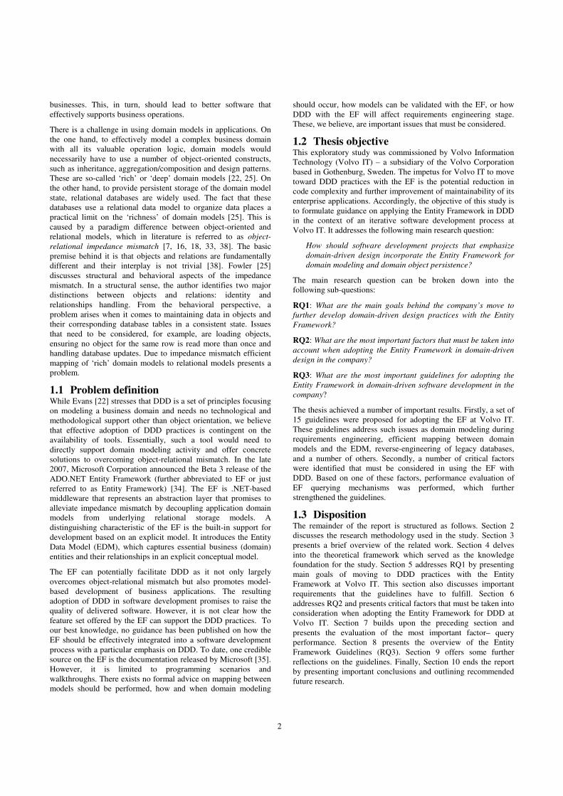
1.1 Problem definition While Evans [22] stresses that DDD is a set of principles focusing
on modeling a business domain and needs no technological and
methodological support other than object orientation, we believe
that effective adoption of DDD practices is contingent on the
availability of tools. Essentially, such a tool would need to
directly support domain modeling activity and offer concrete
solutions to overcoming object-relational mismatch. In the late
2007, Microsoft Corporation announced the Beta 3 release of the
ADO.NET Entity Framework (further abbreviated to EF or just
referred to as Entity Framework) [34]. The EF is .NET-based
middleware that represents an abstraction layer that promises to
alleviate impedance mismatch by decoupling application domain
models from underlying relational storage models. A
distinguishing characteristic of the EF is the built-in support for
development based on an explicit model. It introduces the Entity
Data Model (EDM), which captures essential business (domain)
entities and their relationships in an explicit conceptual model.
The EF can potentially facilitate DDD as it not only largely
overcomes object-relational mismatch but also promotes model-
based development of business applications. The resulting
adoption of DDD in software development promises to raise the
quality of delivered software. However, it is not clear how the
feature set offered by the EF can support the DDD practices. To
our best knowledge, no guidance has been published on how the
EF should be effectively integrated into a software development
process with a particular emphasis on DDD. To date, one credible
source on the EF is the documentation released by Microsoft [35].
However, it is limited to programming scenarios and
walkthroughs. There exists no formal advice on mapping between
models should be performed, how and when domain modeling
should occur, how models can be validated with the EF, or how
DDD with the EF will affect requirements engineering stage.
These, we believe, are important issues that must be considered.
1.2 Thesis objective This exploratory study was commissioned by Volvo Information
Technology (Volvo IT) – a subsidiary of the Volvo Corporation
based in Gothenburg, Sweden. The impetus for Volvo IT to move
toward DDD practices with the EF is the potential reduction in
code complexity and further improvement of maintainability of its
enterprise applications. Accordingly, the objective of this study is
to formulate guidance on applying the Entity Framework in DDD
in the context of an iterative software development process at
Volvo IT. It addresses the following main research question:
How should software development projects that emphasize
domain-driven design incorporate the Entity Framework for
domain modeling and domain object persistence?
The main research question can be broken down into the
following sub-questions:
RQ1: What are the main goals behind the company’s move to
further develop domain-driven design practices with the Entity
Framework?
RQ2: What are the most important factors that must be taken into
account when adopting the Entity Framework in domain-driven
design in the company?
RQ3: What are the most important guidelines for adopting the
Entity Framework in domain-driven software development in the
company?
The thesis achieved a number of important results. Firstly, a set of
15 guidelines were proposed for adopting the EF at Volvo IT.
These guidelines address such issues as domain modeling during
requirements engineering, efficient mapping between domain
models and the EDM, reverse-engineering of legacy databases,
and a number of others. Secondly, a number of critical factors
were identified that must be considered in using the EF with
DDD. Based on one of these factors, performance evaluation of
EF querying mechanisms was performed, which further
strengthened the guidelines.
1.3 Disposition The remainder of the report is structured as follows. Section 2
discusses the research methodology used in the study. Section 3
presents a brief overview of the related work. Section 4 delves
into the theoretical framework which served as the knowledge
foundation for the study. Section 5 addresses RQ1 by presenting
main goals of moving to DDD practices with the Entity
Framework at Volvo IT. This section also discusses important
requirements that the guidelines have to fulfill. Section 6
addresses RQ2 and presents critical factors that must be taken into
consideration when adopting the Entity Framework for DDD at
Volvo IT. Section 7 builds upon the preceding section and
presents the evaluation of the most important factor– query
performance. Section 8 presents the overview of the Entity
Framework Guidelines (RQ3). Section 9 offers some further
reflections on the guidelines. Finally, Section 10 ends the report
by presenting important conclusions and outlining recommended
future research.

3
2. CASE STUDY DESIGN The main purpose of this study was to design a set of guidelines
for incorporating the EF into a domain-driven software
development process at Volvo IT. We used a qualitative
exploratory case study as the methodology behind the study
design [48]. Exploratory case studies are suitable for performing
preliminary studies where it is not clear which phenomena are
significant to look into, or how to quantitatively assess these
phenomena [21]. Moreover, to our best knowledge, research
concerning the adoption of Entity Framework in domain-driven
development is non-existent and current literature provides no
conceptual framework for theorizing. This circumstance makes
the formulation of a proper hypothesis or theory prior to
commencing the study difficult. Another justifiable rationale for
choosing an exploratory case study is the descriptive nature of
research questions. Rather than asking to provide causative links
(why?), research objectives in this study mainly focus on so-called
what?-questions where the major goal is to develop hypotheses
for further scientific inquiry.
The research paradigm of this case study can be characterized as
interpretive. Unlike positivist approach where reality can be
objectively described with measurable properties, interpretive
paradigm seeks to gain knowledge through less precise
constructions such as language and shared meanings [9, 41]. It is
particularly applicable in cases where a degree of uncertainty
surrounds the problem (i.e. very little prior research exists).
Essentially, we tried to understand the phenomena of domain
modeling and object persistence at Volvo IT through the
meanings that people assign to them. The aim was to interpret
how software architects and system analysts understand domain
driven design and object persistence, what they view as best
practices and why. This was achieved through a series of semi-
structured interviews (see later in the section). Our interpretations
were then used in formulating the Entity Framework guidelines,
which can be understood as the tentative theory behind applying
the EF in DDD. The guidelines represent an initial theory – a
theory that must be tested repeatedly to be corroborated or
disproved.
2.1 Context and Subjects The studied company in this research project was Volvo
Information Technology (referred to as Volvo IT henceforth). The
company is a wholly-owned subsidiary of AB Volvo (Volvo
Group), one of the largest industrial groups in the Nordic region.
Volvo IT is the information technology competence center for
Volvo Group. It provides software solutions to support industrial
processes with competencies in Product Lifecycle Management,
SAP solutions, and IT operations. This case study was
commissioned by Software Process Improvement (SPI) group
within Volvo IT, which is responsible for developing and
maintaining processes and methods for application development.
The group was exploring a possibility of adopting the Entity
Framework as a persistence mechanism in software development
projects that emphasize domain-driven design. Accordingly, the
development of guidance on adopting the framework is a unit of
analysis (case) in this study. To our best knowledge, no previous
studies have been performed in this area. Thus, the conclusions
drawn in this case study could potentially inform critical decisions
about incorporating the framework into domain-driven
development in a number of similar enterprises. Due to the
confidentiality agreement with Volvo IT, the guidelines developed
in the thesis are a proprietary asset of the company and, therefore,
only their outline will be presented in this report.
2.2 Study Subjects The subjects in the case study were 1 senior .NET architect, 3
software architects and 2 system analysts. The senior .NET
architect provided much-needed guidance on identifying real
industrial problems with regards to domain-driven development
and object-relational mismatch. He outlined important
benchmarks and requirements that the guidelines had to satisfy.
The rationale for selecting other software architects as primary
subjects was their first-hand exposure to object modeling and
persistence. These architects provided critical data that allowed us
to identify common object modeling and persistence mechanisms,
their characteristics, and also factors affecting the adoption of
Entity Framework at Volvo IT. In involving system analysts in the
study we sought to identify common methods and techniques used
for requirements modeling in the company. In this way, we could
see whether system analysis (in which domain modeling should
play an important part) placed any limitations on using pure
domain-driven design approaches in building business
applications.
2.3 Data Collection and Analysis To increase overall reliability of the study a method of data
triangulation was used. That is, a number of data collection
methods were used to collect evidence. The primary method for
data collection was interviewing. Five semi-structured interviews
were conducted with software architects and system analysts to
gain knowledge about object persistence approaches and domain
modeling in general. Each interview lasted about one hour. Due to
time limitations, interview questions tended to be very focused
and concrete (see Appendix A). Still, an interviewee was allowed
maximum reasonable latitude in elaborating. Interview questions
were refined after each interview to account for new information.
Each interview was recorded. Subsequently, all interviews were
transcribed and the transcripts were analyzed on the subject of any
recurring words or phrases. The transcripts were explicitly
analyzed according to expected outcomes of the thesis work. No
statistical analysis was performed on data extracted from
interviews.
In addition to interviews, extensive body of software
documentation was reviewed from the software portfolio at Volvo
IT. Important information from the documentation was noted and
later revisited for analysis. This initial study made further
interview questions more focused and relevant. Moreover, an
experiment aimed at evaluating the performance of the Entity
Framework query execution provided important input to thesis
result. Finally, a number of informal discussions with the senior
.NET architect also complemented evidence gathered during the
study.
2.4 Study Execution The case study was performed on Volvo IT premises in
Gothenburg (Sweden) during the 20-week spring semester period.
The study was executed in the following stages:
Stage 1: Several initiation interviews were conducted with the
senior .NET architect to identify main goals for transitioning to
DDD with the Entity Framework at Volvo IT. The interviews also
sought to elicit important requirements that the Entity Framework
4
guidelines would need to fulfill. The data collected during the
interviews addressed RQ1 and served as the basis for further
guidelines verification.
Stage 2: Five interviews with software architects and system
analysts were performed. The goal of these interviews was to
identify the most common pattern of working with object
modeling and persistence during software development at the
company. Furthermore, this stage sought to elicit specific
concerns that needed to be addressed in adopting the EF. The data
obtained from the interviews was augmented by observing one
software architect working with a persistence layer in an actual
system. Besides, considerable amount of data was collected
through studying documentation for the Entity Framework and
some internal Volvo IT production systems as well as during
informal discussions with the senior .NET architect. In this way,
not only RQ2 was addressed, but also enough information was
gathered to begin creating the EF guidelines.
Stage 3: Based on the evidence collected during stages 1 and 2 a
set of guidelines for adopting Entity Framework in domain-driven
design were created. RQ3 was thus partially addressed.
Stage 4: The purpose of this final stage was to perform initial
evaluation of the guidelines proposed in Stage 3. The objective
was the verification of understandability and readability of the
guidelines. This was achieved through a joint Entity Framework
workshop where the researcher and all study subjects discussed
the guidelines. Thus, RQ3 was completely addressed.
Eventually, by answering all three research sub-questions we were
able to address the main research question of the case study.
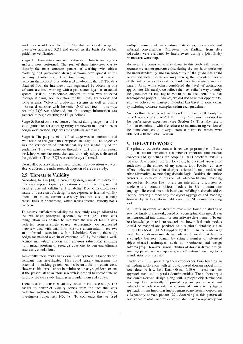
2.5 Threats to Validity According to Yin [48], a case study design needs to satisfy the
following important quality conditions: construct validity, internal
validity, external validity, and reliability. Due to its exploratory
nature this case study’s design is not exposed to internal validity
threat. That is, the current case study does not seek to identify
causal links in phenomena, which makes internal validity not a
concern.
To achieve sufficient reliability the case study design adhered to
the two basic principles specified by Yin [48]. First, data
triangulation was applied to minimize the risk of bias in data
collected from a single source. Accordingly, we augmented
interview data with data from software documentation reviews
and informal discussions with stakeholders. Second, the study
design maintained a chain of evidence [48] by following a well-
defined multi-stage process (see previous subsection) spanning
from initial positing of research questions to deriving ultimate
case study conclusions.
Admittedly, there exists an external validity threat in that only one
company was investigated. This could largely undermine the
potential for making generalizations beyond the immediate case.
However, this threat cannot be minimized to any significant extent
at the present stage as more research is needed to corroborate or
disprove the case study findings in a wider industrial context.
There is also a construct validity threat in this case study. The
danger to construct validity comes from the fact that data
collection methods and resulting evidence may be biased due to
investigator subjectivity [45, 48]. To counteract this we used
multiple sources of information: interviews, documents and
informal conversations. Moreover, the findings from data
collection were evaluated by interviewees during a joint Entity
Framework workshop.
However, the construct validity threat to this study still remains
because we cannot guarantee that during the one-hour workshop
the understandability and the readability of the guidelines could
be verified with absolute certainty. During the presentation some
of the interviewees deemed the guidelines too abstract in their
pattern form, while others considered the level of abstraction
appropriate. Ultimately, we believe the most reliable way to verify
the guidelines in this regard would be to test them in a real
development project. However, we did not have this opportunity.
Still, we believe we managed to curtail this threat to some extent
by including concrete examples within each guideline.
Another threat to construct validity relates to the fact that only the
Beta 3 version of the ADO.NET Entity Framework was used in
the performance experiment (see Section 7). Thus, the results
from an experiment with the release-to-manufacturing version of
the framework could diverge from our results, which were
obtained with the Beta 3 version.
3. RELATED WORK The primary source for domain-driven design principles is Evans
[22]. The author introduces a number of important fundamental
concepts and guidelines for adopting DDD practices within a
software development project. However, he does not provide the
guidelines in the context of any specific tool. Fowler [25] also
offers a relevant discussion of object-oriented domain models and
other alternatives to modeling domain logic. Besides, the author
presents a detailed discussion of object-relational mapping
approaches. Nilsson [36] offers an interesting discussion of
implementing domain object models in C# programming
language. He considers such issues as building a domain object
factory, creating a repository for object aggregates and mapping
domain objects to relational tables with the NHibernate mapping
tool.
Still, after an extensive literature review we found no studies of
how the Entity Framework, based on a conceptual data model, can
be incorporated into domain-driven software development. To our
best knowledge, there is no research into how rich domain models
should be mapped and persisted to a relational database via an
Entity Data Model (EDM) supplied by the EF. As the reader may
recall, by rich domain models we understand models that describe
a complex business domain by using a number of advanced
object-oriented techniques, such as inheritance and design
patterns [25]. However, several studies of domain-driven design,
handling persistence and applying object/relational mapping tools
in industrial projects exist.
Landre et al.[30], presenting their experiences from building an
oil trading application with an object-based domain model in its
core, describe how Java Data Objects (JDO) - based mapping
approach was used to persist domain entities. The authors argue
that domain-driven design along with a proper object-relational
mapping tool generally improved system performance and
reduced the code size relative to some of their existing legacy
applications. An important improvement came from incorporating
a Repository domain pattern [22]. According to this pattern all
persistence-related code was encapsulated inside a repository and

5
the resulting business logic code, oblivious of persistence
infrastructure, operated only on pure business entities. This in turn
resulted in cleaner code, which facilitated communication within
the team. However, it was difficult at first, as authors noted, to
change the mindset of database-oriented developers to an object-
oriented way of formulating JDO queries. The JDO mapping
approach did eventually pay off as developers no longer had to
concern themselves with the minute details of the relational
database schema and instead focus on core business entities. Still,
while the authors presented important drivers behind migrating to
a mapping layer, no meaningful guidelines were offered on how
mapping tools should be integrated into domain-driven
development or what role domain modeling should play in the
process.
Wu [47] presents an enterprise system intended to assess human
performance. The system domain model was generated by the
Entity Object framework3. This framework closely resembles
Repository pattern [22]: it encapsulates all persistence-related
issues through object-relational mapping and thus enables a
developer to work with a pure object-based domain model. The
author claims that the architecture based on the Entity Object
framework effectively decoupled the database from the rest of the
application and improved the overall design since developers no
longer had to be aware of the intricacies in the relational database
schema. Still, the author fails to examine the framework in the
wider context of domain-driven design and domain modeling.
A promising approach to domain-driven design is proposed by
Philippi [38]. The author discusses experiences from developing a
model-driven tool that allows visually modeling an object domain
model and then automatically generating persistence-related code
and data definition language (DDL) SQL queries. The mapping
between domain objects and relational tables is specified with a
wizard tool. Essentially, an application developer specifies
different trade-off criteria, such as maintainability,
understandability, which in return generates mappings for a
chosen object-relational tool vendor. The system currently
supports TopLink. The author also discusses how mappings of
attributes, associations and inheritance hierarchies can be
performed. He also makes a seminal analysis of different
mappings in terms of understandability, maintainability, storage
space and performance. We actively used the results from this
analysis in formulating mapping patterns which are a part of the
Entity Framework guidelines. Finally, the author argues that the
starting point for the automatic generation of object-relational
mappings is an application object model – a domain model.
Generally, the problem of a paradigm schism between object and
relational models has been a longstanding one [18] and has been
widely studied [4, 7, 11, 15, 25, 29, 33, 46]. Several pattern
languages have been created, which catalogue best practices in
mapping objects to relations [15, 29]. We used a number of these
patterns to complement our own mapping patterns, especially
when it came to mapping the EDM to a relational model.
Moreover, to define the pattern language we consulted [29].
Cook and Ibrahim [18] review numerous issues affecting the
language/database integration and develop these issues into
criteria against which different solutions to impedance mismatch
3 .NET-based enterprise framework for domain-driven design. Available
at http://neo.sourceforge.net/
can be evaluated. The authors also present the results from a
qualitative evaluation of existing solutions. Their study included
such tools as object/relational mapping tools, object-oriented
database systems and orthogonal persistence systems.
Researchers and practitioners have developed a number of
solutions helping to mitigate or altogether eliminate the object-
relational impedance mismatch. Some of the proposed solutions
are discussed below.
One solution that completely prevents the mismatch is to use
object-oriented database systems (OODBS). OODBS enable a so-
called transparent persistence [36], whereby both persistent
objects and in-memory objects are accessed in the same way. This
is achieved through storing objects directly rather than
transforming them to relational constructs before persisting [49].
As a result only one object-based domain model needs to exist in
the application, resulting in overall design improvements [49].
However, predictions of a wide adoption of OODBS did not
materialize as they have achieved only a 2% share of the
international database market [32]. Relational databases remain
the dominant persistence mechanism [15].
Another interesting approach to persistence is orthogonal
persistence [5, 40]. Orthogonality in this sense considers
persistence as merely an aspect of an application. The basic tenet
behind orthogonal persistence is the obliviousness of the
persistence concern. Once persistence has been “aspectisized”, the
rest of the application can be built as if no data needs to be
persisted. The persistence mechanism can be plugged in at a later
time. There have also been some attempts to embed persistence
capabilities directly into a programming language [12].
4. THEORETICAL FRAMEWORK This section seeks to define important terms actively used
throughout the thesis report. It contrasts two approaches to
addressing domain logic in enterprise applications. The section
then introduces the basic concepts of domain-driven design.
Finally, the section delves into the Entity Framework: its
architecture and its basic premise of conceptual data
programming.
4.1 Structuring domain logic Oldfield [37] discusses three types of requirements that any
application software has to fulfill. First, there are requirements
originating from users, which determine system’s purpose and
how the system is used. These requirements are usually captured
in Use Cases [10]. Second, there are non-functional requirements
that capture quality attributes of a system: reliability, performance,
security and many others. Finally, there are domain requirements.
A domain of a software product is the subject area in which the
user applies this product [22]. Domain requirements capture
essential domain concepts, their relationships and important rules.
Business rules, for example, constrain and control the way a
business operates. In this report, we use the term business rules
interchangeably with terms like domain logic, business logic or
application logic. We also use the terms business object, domain
object and business entity interchangeably in this report.
Historically, in the object community there have been several
approaches to organizing and implementing business logic in
applications. Fowler [25] identified three patterns of organizing
domain logic in enterprise applications: table-based record set

6
(Table Module), procedural (Transaction Script) and domain
model-based (Domain Model). Table Module and Transaction
Script patterns are largely database-driven in a sense that the
relational model determines the structuring of domain objects and
their relationships. Subsequently, all logic is concentrated in a set
of heavyweight application services operating on database table-
like objects (data containers), instead of actual business entities
where they naturally belong. Domain Model (DM) pattern, on the
other hand, stresses the importance of decoupling the object
model from the database model and structuring the whole
application around the object-based domain model4 – a domain-
driven approach [22]. According to this pattern, encapsulating all
domain logic in a set of interconnected business objects (domain
model) is a way to manage complexity inherent in most
businesses. In the following subsections we contrast Transaction
Script and Domain Model patterns for illustrating two distinct
approaches to structuring domain logic.
4.1.1 Procedural style (Transaction Script) The basic premise behind this style is that all application logic is
organized into a set of procedure-like scripts (“fat services”), each
of which handles a single request from the presentation layer.
Normally, a single script is responsible for one business
transaction, such as book a hotel room, transfer money from one
account to another, etc [25]. Figure 1 illustrates a part of a
banking application5 built with the Transaction Script pattern.
The most salient characteristic of this design approach is that
domain objects/entities (Account, Customer and
BankingTransaction) do not encapsulate any business logic per se.
Domain objects in this model represent bare data containers (with
getter/setter fields), which is in a fundamental conflict with the
object-oriented paradigm of encapsulating both data and behavior
[23]. In fact, the structure of the database schema largely
determines the design of these objects. Fowler [23] refers to such
a model as anemic domain model – database-driven with no
domain logic. While there is nothing wrong with a domain model
structure closely resembling that of a relational model (one-to-one
mapping), a mechanic derivation of a domain object model from a
database with no regard to the principle of encapsulation could
cause problems in later stages of development. Most importantly,
this could lead to broken abstractions in the application. For
example, a real-world entity Order could be split into several
Order-related tables in the database due to normalization
requirements. Following the procedural pattern, these tables
would be one-to-one mapped to domain objects in the data tier.
As a result, the Order entity will be fragmented over a number of
related objects in the object model and the mental model of the
application will be disrupted. It is necessary to remember that a
relational model with its mathematical underpinnings may not be
suited for modeling real world domains at a high level of
abstraction. It is a logical representation of how data is stored in
4 Essentially, a domain model is a way to express domain requirements by
explicitly capturing essential business concepts, their relationships and
rules in a concrete model.
5 This example was inspired by the presentation made by Chris
Richardson on “Improving Application Design with a Rich Domain
Model”. Available at
http://www.parleys.com/display/PARLEYS/Improving+Application+De
sign+with+a+Rich+Domain+Model?showComments=true
the database [4, 11]. In fact, recognizing this limitation in
relational modeling, Peter Chen in 1976 devised the entity-
relationship model approach [17] to conceptual data modeling.
Domain object models, unlike their relational counterparts, model
conceptual real-world business entities and operate at a higher
abstraction level.
All business logic in the procedural style resides in the business
tier within MoneyTransferService. This service performs a
transfer of money assets from one account to another. The service
definition executes all business rules (such as overdrafting policy)
before crediting and debiting accounts.
Web TierASPXController
Business Tier
+TransferMoney(in fromAccount, in toAccount, in amount)
MoneyTransferService
Data Tier
-accountID
-accountType
-balance
Account
-customerID
-firstName
-lastName
-address1
-address2
Customer
-transactionID
-amount
-date
BankingTransaction
-fromAccount
1
*
-toAccount1
*
1
*
AccountaccountID
accountType
accountBalance
customer_FK
BankingTransactiontransactionID
amount
date
fromAccount_FK
toAccount_FK
CustomercustomerID
firstName
lastName
address1
address2
Maps one-to-one to
Web Tier
Figure 1: Part of a banking application built in a procedural
style
This design style has some properties that make it attractive for
building non-sophisticated enterprise applications [25]. First, it is
easy to add new functionality by implementing a new transaction
script. Second, it does not require significant object modeling
skills. In fact, some enterprise application frameworks (e.g. J2EE

7
EJB6) even encourage this style. However, a significant
disadvantage of this approach is that it does not scale well to
complex business domains. As more and more functionality is
added, transaction scripts tend to multiply and swell in size. As a
result, the potential for the same business logic to be repeated in
several places becomes more pronounced, which seriously
undermines application maintainability. Another problem with the
style, as we mentioned, is that the resulting object model is largely
database-driven – hence, some adverse implications for
application abstractions.
4.1.2 Domain Model style The Domain Model pattern prescribes offloading all the domain
logic from services (transaction scripts) and encapsulating it
inside a domain layer – a layer of objects that model the business
area. Essentially, the business logic is modeled as operations on
classes and spread among a collection of domain objects. See
Figure 2 for the comparison of the two design approaches.
Figure 2: Transitioning from procedural database-driven
design to domain-driven design (adapted from Richardson7)
Most importantly, a domain model is intended to be purely
conceptual: classes in this model directly correspond to real-world
objects. It is, therefore, likely that the domain model will often
diverge from its relational counterpart. To ensure that data can be
transparently passed between the two potentially diverging models
(due to object-relational impedance mismatch), Fowler [25]
suggests that a Data Mapper be used. The sole purpose of the Data
Mapper is to move “data between objects and a database while
keeping them independent of each other and the mapper itself”
[25]. It could be understood as a translator that performs data
transformations as it crosses object-relational boundary. Object-
relational mapping tools emerged as a result of the need for
automatic data translation and mapping of object models to
database models. To date, a number of commercial (LLBLGen
Pro, Apple WebObjects) as well as open source
(Hibernate/NHibernate as the most popular) solutions exist. In
fact, a whole new discipline appeared as a result of pursuing
6 It is notable how its reference architecture encourages Transaction Script
thinking: Enterprise Java Beans (EJB) implement procedures by
operating on an anemic Entity Bean-based model.
7 See
http://www.parleys.com/display/PARLEYS/Improving+Application+De
sign+with+a+Rich+Domain+Model?showComments=true
application design with the domain model at the core – domain-
driven design. Next sub-section addresses this approach at length.
There are a number of benefits to having a domain model at the
core of the application design. Firstly, because the domain model
is decoupled from the relational model, such design reflects the
reality of business better. Clients to a domain model are able to
operate in terms of real business concepts. Secondly, a domain
model represents a model of business and its core concepts. These
concepts rarely change and are quite stable. Therefore, by
encapsulating all business-related functionality in a domain
model, it becomes possible to reuse the model in a new context
(new applications, for example). Finally, as Evans [22] stresses, a
domain model represents a ubiquitous language – a common
language shared by domain experts, developers, managers and
other stakeholders. Ubiquitous language facilitates shared
understanding of the domain, and, ultimately, leads to better
software that is more in line with the user concerns and needs.
4.2 Domain-driven design Evans [22] sees domain-driven design (DDD) as the
“undercurrent of the object community”. The principles of DDD
have been known for a long time, yet only recently has the DDD
gained increased attention and interest from software developers
[22]. The fundamental premise behind the DDD is that most
software projects should primarily focus on the problem domain
and domain logic. Application design should be based on a
domain model. This is achieved by closely mapping domain
concepts to software artifacts. DDD should not be viewed as a
software development process in its own right. Rather, it is a set
of guiding principles, practices and techniques aimed at
facilitating software projects dealing with complicated domains.
DDD should be applied in the context of an iterative development
process, where developers and domain experts have a close
relationship.
The centerpiece of the DDD philosophy is a domain model [22].
A domain model represents essential knowledge about the
problem area. It is a tool for overcoming information overload and
overall complexity when a development team attempts to extract
domain knowledge from system users. A domain model “is not
just the knowledge in a domain expert’s head; it is a rigorously
organized and selective abstraction of that knowledge” [22] (p.
3).
Fowler [25] offers a relevant discussion of domain models. A
domain model captures the business area in which an application
operates. It models essential business entities (domain objects)
and their intrinsic qualities such as attributes or constraints from a
conceptual perspective. But above all, a domain model
encapsulates all domain logic, which might include business rules,
constraints and other important components.
Importantly, a domain model is not necessarily a diagram or some
other illustration, rather, it is the notion that a diagram seeks to
convey. A diagram can communicate a model, as can more textual
representation. However, considering that object-orientation is
largely based on modeling real-life objects, object-oriented
models (namely, a class diagram) have become a de-facto
standard for capturing domain knowledge (see Appendix C).
In a sense that DDD espouses a model as the primary artifact in
software development, it is closely related to model-driven
8
development (MDD) philosophy. Both methodologies strive to
reduce complexity inherent in application domains by raising the
level of abstraction in software construction to a level that is
closer to a problem domain [42]. However, unlike DDD, MDD
stresses automatic generation of programs based on corresponding
models [43]. In this context, DDD does not see the domain model
as a platform for code generation. Rather, the domain model in
DDD is considered to be a facilitator of a common language
shared by all stakeholders [22]. Moreover, instead of having just
one central model (e.g. a domain model in DDD), MDD
prescribes producing a number of models targeted at different
abstraction levels [1]. Such models may include computation-
independent models (domain models), platform-independent and
platform-specific models [1, 26].
4.2.1 The building blocks of domain-driven design A domain model seeks to bridge the gap between analysis and
design by addressing concerns belonging to both of the activities.
One can find not only familiar business objects/entities in the
model (business analysis model), but also objects representing
services, repositories and factories (design model). Figure 3
presents a navigation map of the DDD concepts.
Figure 3: A navigation map of the language of domain-driven
design
(source: Evans [22])
In the paragraphs to follow, we briefly discuss each of the
building blocks. For a more detailed text the reader is referred to
Evans’ book on domain-driven design [22].
4.2.1.1 Layered architecture From an architectural viewpoint, a domain model comprises a
distinct layer in an application that encapsulates a set of stable
business object types [44]. In DDD a domain layer constitutes the
core of the application design and architecture. It is responsible
for all fundamental business rules. It is in the domain layer that
the model of the problem area resides. This appears in sharp
contrast with the procedural approach in Transaction Script where
all domain logic is concentrated in the application (service) layer.
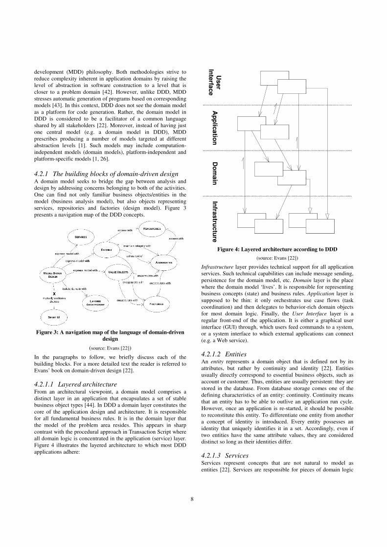
Figure 4 illustrates the layered architecture to which most DDD
applications adhere:
Ap
plic
atio
nD
om
ain
Infra
stru
ctu
reU
ser
Inte
rface
Figure 4: Layered architecture according to DDD
(source: Evans [22])
Infrastructure layer provides technical support for all application
services. Such technical capabilities can include message sending,
persistence for the domain model, etc. Domain layer is the place
where the domain model ‘lives’. It is responsible for representing
business concepts (state) and business rules. Application layer is
supposed to be thin: it only orchestrates use case flows (task
coordination) and then delegates to behavior-rich domain objects
for most domain logic. Finally, the User Interface layer is a
regular front-end of the application. It is either a graphical user
interface (GUI) through, which users feed commands to a system,
or a system interface to which external applications can connect
(e.g. a Web service).
4.2.1.2 Entities An entity represents a domain object that is defined not by its
attributes, but rather by continuity and identity [22]. Entities
usually directly correspond to essential business objects, such as
account or customer. Thus, entities are usually persistent: they are
stored in the database. From database storage comes one of the
defining characteristics of an entity: continuity. Continuity means
that an entity has to be able to outlive an application run cycle.
However, once an application is re-started, it should be possible
to reconstitute this entity. To differentiate one entity from another
a concept of identity is introduced. Every entity possesses an
identity that uniquely identifies it in a set. Accordingly, even if
two entities have the same attribute values, they are considered
distinct so long as their identities differ.
4.2.1.3 Services Services represent concepts that are not natural to model as
entities [22]. Services are responsible for pieces of domain logic
9
that cannot be encapsulated in an entity. A service can be
considered as an interface or an entry point into the domain model
for external clients. A proper service possesses three important
characteristics[22]: 1. the operation a service implements directly
relates to a business concept; 2. the service interface is defined in
terms of the elements of a domain model (intention-revealing
interface); 3. a service operation is stateless.
As an example of a ‘good’ domain service, consider the case
when an application implements a transfer of funds between two
bank accounts. The transfer operation directly relates to the
banking domain term “funds transfer”. Modeling the transfer
operation on one of the entities (e.g. account) would be somewhat
undesirable because the operation involves two accounts. Thus, a
funds transfer operation is best factored into a separate domain
service operating on domain entities (see Appendix C). A service
can be directly accessible from the application or a presentation
layer.
4.2.1.4 Aggregates An aggregate is a set of related entities that can be treated as a
unit for the purpose of data changes [22]. In a system with
persistent data storage there must be a scope for a transaction to
change data. Consider a case when a certain number of related
entities are loaded from the database into the main memory. After
modifying the state of some of the objects a user attempts to save
their work. A database transaction is spun to maintain data
consistency during the save operation. However, should the
transaction apply only to the saved object or should it also apply
to its related object(s)? Another issue arises when a deletion of a
domain object occurs. Should the related objects also be deleted
from the persistent storage? Essentially, an aggregate addresses
these issues by identifying a graph of objects that are treated as a
unit. Any operation performed on an object within the graph
automatically applies to all other graph members (e.g. a
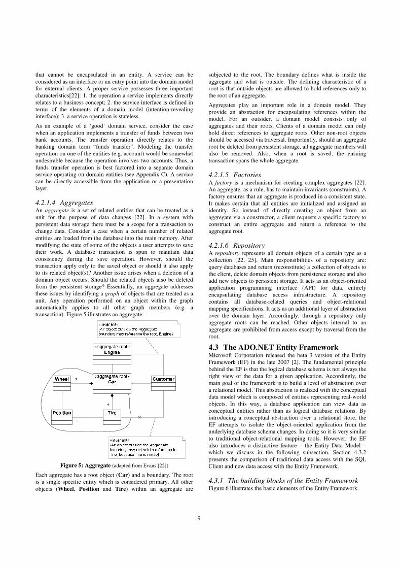
transaction). Figure 5 illustrates an aggregate.
Figure 5: Aggregate (adapted from Evans [22])
Each aggregate has a root object (Car) and a boundary. The root
is a single specific entity which is considered primary. All other
objects (Wheel, Position and Tire) within an aggregate are
subjected to the root. The boundary defines what is inside the
aggregate and what is outside. The defining characteristic of a
root is that outside objects are allowed to hold references only to
the root of an aggregate.
Aggregates play an important role in a domain model. They
provide an abstraction for encapsulating references within the
model. For an outsider, a domain model consists only of
aggregates and their roots. Clients of a domain model can only
hold direct references to aggregate roots. Other non-root objects
should be accessed via traversal. Importantly, should an aggregate
root be deleted from persistent storage, all aggregate members will
also be removed. Also, when a root is saved, the ensuing
transaction spans the whole aggregate.
4.2.1.5 Factories A factory is a mechanism for creating complex aggregates [22].
An aggregate, as a rule, has to maintain invariants (constraints). A
factory ensures that an aggregate is produced in a consistent state.
It makes certain that all entities are initialized and assigned an
identity. So instead of directly creating an object from an
aggregate via a constructor, a client requests a specific factory to
construct an entire aggregate and return a reference to the
aggregate root.
4.2.1.6 Repository A repository represents all domain objects of a certain type as a
collection [22, 25]. Main responsibilities of a repository are:
query databases and return (reconstitute) a collection of objects to
the client, delete domain objects from persistence storage and also
add new objects to persistent storage. It acts as an object-oriented
application programming interface (API) for data, entirely
encapsulating database access infrastructure. A repository
contains all database-related queries and object-relational
mapping specifications. It acts as an additional layer of abstraction
over the domain layer. Accordingly, through a repository only
aggregate roots can be reached. Other objects internal to an
aggregate are prohibited from access except by traversal from the
root.
4.3 The ADO.NET Entity Framework Microsoft Corporation released the beta 3 version of the Entity
Framework (EF) in the late 2007 [2]. The fundamental principle
behind the EF is that the logical database schema is not always the
right view of the data for a given application. Accordingly, the
main goal of the framework is to build a level of abstraction over
a relational model. This abstraction is realized with the conceptual
data model which is composed of entities representing real-world
objects. In this way, a database application can view data as
conceptual entities rather than as logical database relations. By
introducing a conceptual abstraction over a relational store, the
EF attempts to isolate the object-oriented application from the
underlying database schema changes. In doing so it is very similar
to traditional object-relational mapping tools. However, the EF
also introduces a distinctive feature – the Entity Data Model –
which we discuss in the following subsection. Section 4.3.2
presents the comparison of traditional data access with the SQL
Client and new data access with the Entity Framework.
4.3.1 The building blocks of the Entity Framework Figure 6 illustrates the basic elements of the Entity Framework.

10
ADO.NET Entity Framework
Entity Framework Metadata Layers
CONCEPTUAL
MAPPING
LOGICAL
Entity Data Model
Entity-to-Relation
mapping specification
Relational database
model
Datasource
Entity Client
Entity SQL ObjectServices LINQ to Entities
Figure 6: Entity Framework architecture (adapted from [4])
EF is claimed to largely overcome impedance mismatch problem
by elevating the level of abstraction in data programming from
logical (relational schema) to conceptual [4, 11]. This implies that
the application can be oblivious of the relational schema by
accessing persistent data through an explicit conceptual model
called Entity Data Model (EDM). EDM abstracts away logical
(relational schema) design from the rest of the application by
exposing high-level business entities as data containers. In this
way, persistence layer is decoupled from the application layer,
which mitigates impedance mismatch problem.
4.3.1.1 The Entity Data Model The Entity Data Model (EDM) follows the notation of the Entity-
Relationship model [17]. The key concepts introduced by the
EDM are [4]:
• Entity: entities directly correspond to the same concept in
the domain-driven design. They are characterized by
continuity (persistent) and have a unique identity. Entities in
the EDM represent conceptual abstractions over the
relational model and, therefore, model exclusively real-life
objects. Each entity is an instance of Entity Type (e.g.
Employee, Order). At runtime entities are grouped into
Entity Sets.
• Relationship: relationships associate entities to one another.
Currently, the EDM supports three types of relationships:
association, containment (entities contained are dependent
on the parent entity – similar to object composition) and
inheritance.
Consisting of conceptual entities and corresponding relationships
the EDM hides the relational model of the database from the rest
of the application. It corresponds to a conceptual layer in the EF.
The EF performs mapping of a conceptual layer to a logical layer
(relational model) by introducing two additional layers below the
EDM: mapping specification and storage schema definition.
Storage schema definition is essentially a specification of a
relational database model. Mapping specification reconciles the
object-relational impedance mismatch by mapping conceptual
entities in the EDM to relations (tables) in the storage schema.
4.3.1.2 Entity client While the concepts of the EDM and mapping may seem abstract
at first, during program execution they are made concrete with a
special ADO.NET8 interface – EntityClient. Entity client is a data-
access provider for the EF, which is also called mapping provider.
It encapsulates and handles database and EDM connections. It is
very similar to a regular SQL Client in ADO.NET, which allows
applications to connect to relational data sources. However, unlike
SQL Client, Entity Client provides access to data in the EDM
terms. In this case, the EDM acts as a conceptual database similar
to Repository concept from DDD.
4.3.1.3 Entity SQL When an application uses the Entity Framework and its mapping
provider to access data, it no longer connects directly to the
database. Rather, the whole application operates in terms of the
EDM entities. Therefore, it is no longer possible to use the native
database query language for retrieving data. The EF enables
querying against the EDM by introducing a query language –
Entity SQL (eSQL) [4]. The overall structure and syntax of Entity
SQL is very similar to those of the standard SQL (usual SELECT-
FROM-WHERE sequence). Unlike the SQL, eSQL introduces
additional features such as support for navigational properties (it
is possible to traverse entities instead of using JOIN) and support
for inheritance.
4.3.1.4 Object Services Considering that most applications are written in object-oriented
languages and thus operate on objects, the EF introduces Object
Services feature [4]. The EF includes a tool that, given the EDM
definition, will generate a domain object layer for use in the
application. By using Object Services it is possible to query the
EDM with eSQL and retrieve strongly-typed objects from the
store. In the same manner, once the application has finished
working with objects in memory, it only has to invoke the
SaveChanges operation. Subsequently, the mapping provider will
persist these objects by transforming them into corresponding
SQL statements to relational database.
4.3.1.5 LINQ to Entities When it comes to querying databases for data, application
programmers have to use two languages for this purpose: the
query language and the programming language for manipulating
the retrieved data. This not only implies that programmers have to
master two distinct languages, but also that queries specified as
8 ADO.NET is a set of software components that can be used by
application developers to access data and data services in .NET
environment.
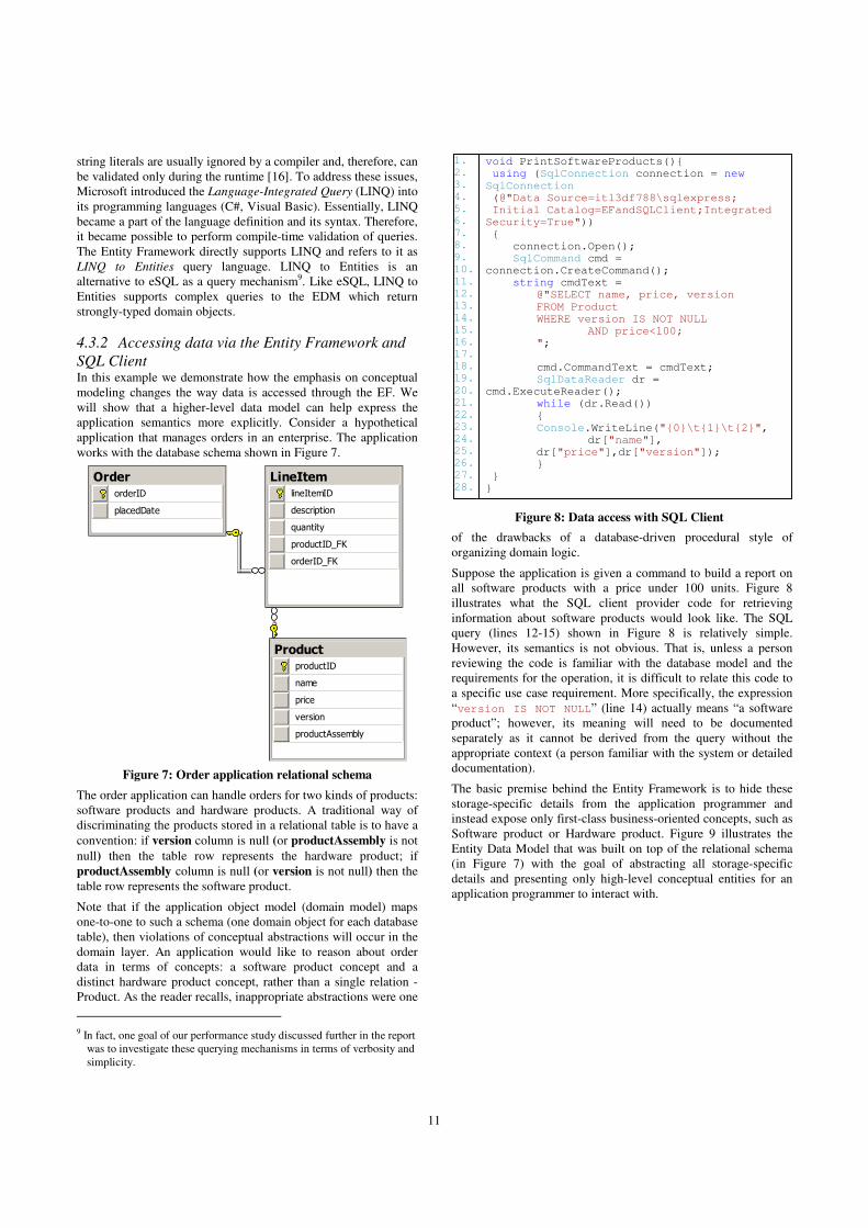
11
string literals are usually ignored by a compiler and, therefore, can
be validated only during the runtime [16]. To address these issues,
Microsoft introduced the Language-Integrated Query (LINQ) into
its programming languages (C#, Visual Basic). Essentially, LINQ
became a part of the language definition and its syntax. Therefore,
it became possible to perform compile-time validation of queries.
The Entity Framework directly supports LINQ and refers to it as
LINQ to Entities query language. LINQ to Entities is an
alternative to eSQL as a query mechanism9. Like eSQL, LINQ to
Entities supports complex queries to the EDM which return
strongly-typed domain objects.
4.3.2 Accessing data via the Entity Framework and
SQL Client In this example we demonstrate how the emphasis on conceptual
modeling changes the way data is accessed through the EF. We
will show that a higher-level data model can help express the
application semantics more explicitly. Consider a hypothetical
application that manages orders in an enterprise. The application
works with the database schema shown in Figure 7.
Order
orderID
placedDate
LineItemlineItemID
description
quantity
productID_FK
orderID_FK
ProductproductID
name
price
version
productAssembly
Figure 7: Order application relational schema
The order application can handle orders for two kinds of products:
software products and hardware products. A traditional way of
discriminating the products stored in a relational table is to have a
convention: if version column is null (or productAssembly is not
null) then the table row represents the hardware product; if
productAssembly column is null (or version is not null) then the
table row represents the software product.
Note that if the application object model (domain model) maps
one-to-one to such a schema (one domain object for each database
table), then violations of conceptual abstractions will occur in the
domain layer. An application would like to reason about order
data in terms of concepts: a software product concept and a
distinct hardware product concept, rather than a single relation -
Product. As the reader recalls, inappropriate abstractions were one
9 In fact, one goal of our performance study discussed further in the report
was to investigate these querying mechanisms in terms of verbosity and
simplicity.
of the drawbacks of a database-driven procedural style of
organizing domain logic.
Suppose the application is given a command to build a report on
all software products with a price under 100 units. Figure 8
illustrates what the SQL client provider code for retrieving
information about software products would look like. The SQL
query (lines 12-15) shown in Figure 8 is relatively simple.
However, its semantics is not obvious. That is, unless a person
reviewing the code is familiar with the database model and the
requirements for the operation, it is difficult to relate this code to
a specific use case requirement. More specifically, the expression
“version IS NOT NULL” (line 14) actually means “a software
product”; however, its meaning will need to be documented
separately as it cannot be derived from the query without the
appropriate context (a person familiar with the system or detailed
documentation).
The basic premise behind the Entity Framework is to hide these
storage-specific details from the application programmer and
instead expose only first-class business-oriented concepts, such as
Software product or Hardware product. Figure 9 illustrates the
Entity Data Model that was built on top of the relational schema
(in Figure 7) with the goal of abstracting all storage-specific
details and presenting only high-level conceptual entities for an
application programmer to interact with.
void PrintSoftwareProducts(){ using (SqlConnection connection = new
SqlConnection (@"Data Source=itl3df788\sqlexpress; Initial Catalog=EFandSQLClient;Integrated Security=True")) { connection.Open(); SqlCommand cmd = connection.CreateCommand(); string cmdText =
@"SELECT name, price, version
FROM Product WHERE version IS NOT NULL
AND price<100; "; cmd.CommandText = cmdText; SqlDataReader dr = cmd.ExecuteReader(); while (dr.Read())
{ Console.WriteLine("{0}\t{1}\t{2}", dr["name"], dr["price"],dr["version"]);
} } }
1.
2. 3. 4. 5. 6. 7. 8. 9. 10.
11. 12. 13. 14. 15. 16. 17. 18. 19.
20. 21. 22. 23. 24. 25. 26. 27. 28.
Figure 8: Data access with SQL Client
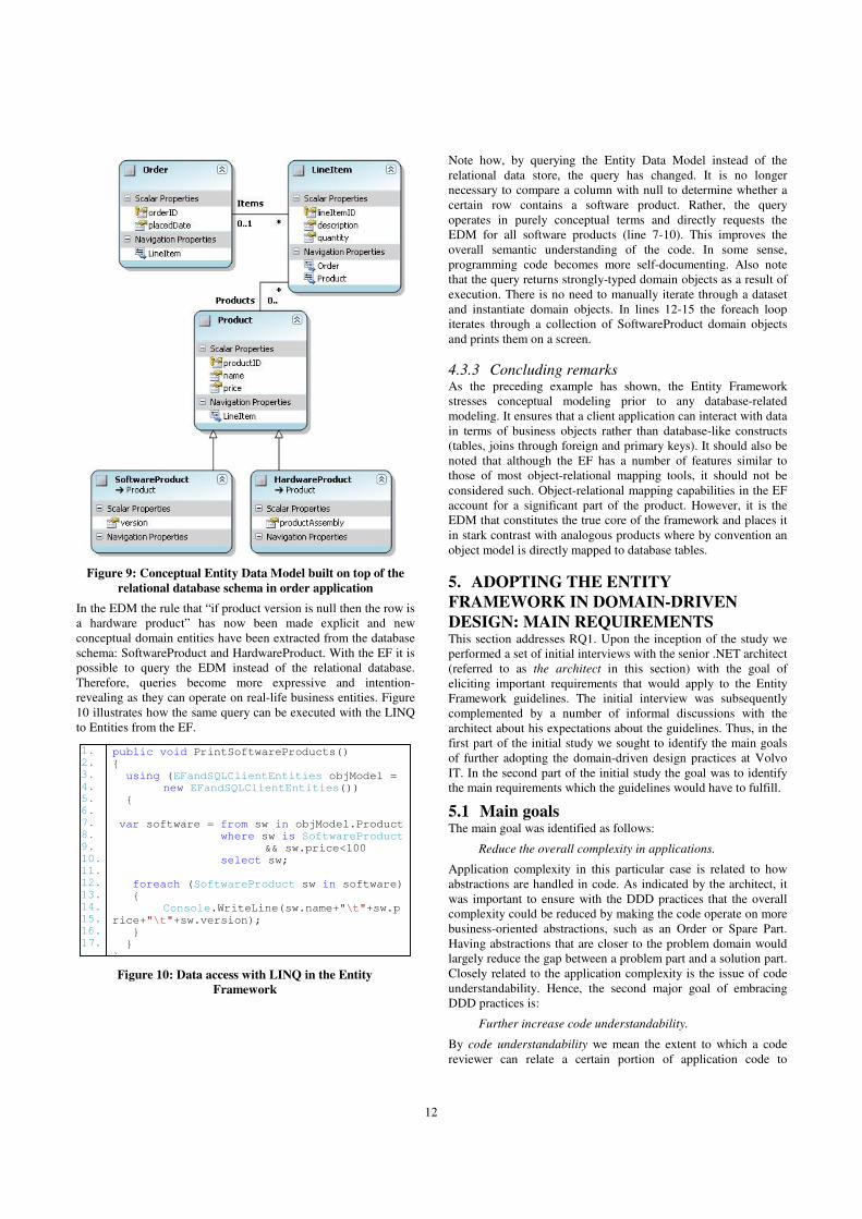
12
public void PrintSoftwareProducts() { using (EFandSQLClientEntities objModel = new EFandSQLClientEntities()) {
var software = from sw in objModel.Product where sw is SoftwareProduct && sw.price<100 select sw; foreach (SoftwareProduct sw in software) {
Console.WriteLine(sw.name+"\t"+sw.p
rice+"\t"+sw.version); } } }
Figure 9: Conceptual Entity Data Model built on top of the
relational database schema in order application
In the EDM the rule that “if product version is null then the row is
a hardware product” has now been made explicit and new
conceptual domain entities have been extracted from the database
schema: SoftwareProduct and HardwareProduct. With the EF it is
possible to query the EDM instead of the relational database.
Therefore, queries become more expressive and intention-
revealing as they can operate on real-life business entities. Figure
10 illustrates how the same query can be executed with the LINQ
to Entities from the EF.
Note how, by querying the Entity Data Model instead of the
relational data store, the query has changed. It is no longer
necessary to compare a column with null to determine whether a
certain row contains a software product. Rather, the query
operates in purely conceptual terms and directly requests the
EDM for all software products (line 7-10). This improves the
overall semantic understanding of the code. In some sense,
programming code becomes more self-documenting. Also note
that the query returns strongly-typed domain objects as a result of
execution. There is no need to manually iterate through a dataset
and instantiate domain objects. In lines 12-15 the foreach loop
iterates through a collection of SoftwareProduct domain objects
and prints them on a screen.
4.3.3 Concluding remarks As the preceding example has shown, the Entity Framework
stresses conceptual modeling prior to any database-related
modeling. It ensures that a client application can interact with data
in terms of business objects rather than database-like constructs
(tables, joins through foreign and primary keys). It should also be
noted that although the EF has a number of features similar to
those of most object-relational mapping tools, it should not be
considered such. Object-relational mapping capabilities in the EF
account for a significant part of the product. However, it is the
EDM that constitutes the true core of the framework and places it
in stark contrast with analogous products where by convention an
object model is directly mapped to database tables.
5. ADOPTING THE ENTITY
FRAMEWORK IN DOMAIN-DRIVEN
DESIGN: MAIN REQUIREMENTS This section addresses RQ1. Upon the inception of the study we
performed a set of initial interviews with the senior .NET architect
(referred to as the architect in this section) with the goal of
eliciting important requirements that would apply to the Entity
Framework guidelines. The initial interview was subsequently
complemented by a number of informal discussions with the
architect about his expectations about the guidelines. Thus, in the
first part of the initial study we sought to identify the main goals
of further adopting the domain-driven design practices at Volvo
IT. In the second part of the initial study the goal was to identify
the main requirements which the guidelines would have to fulfill.
5.1 Main goals The main goal was identified as follows:
Reduce the overall complexity in applications.
Application complexity in this particular case is related to how
abstractions are handled in code. As indicated by the architect, it
was important to ensure with the DDD practices that the overall
complexity could be reduced by making the code operate on more
business-oriented abstractions, such as an Order or Spare Part.
Having abstractions that are closer to the problem domain would
largely reduce the gap between a problem part and a solution part.
Closely related to the application complexity is the issue of code
understandability. Hence, the second major goal of embracing
DDD practices is:
Further increase code understandability.
By code understandability we mean the extent to which a code
reviewer can relate a certain portion of application code to
1. 2. 3.
4. 5. 6. 7. 8. 9. 10. 11. 12.
13. 14. 15. 16. 17.
Figure 10: Data access with LINQ in the Entity
Framework

13
corresponding system requirements. This might be necessary, for
example, during a system maintenance cycle. Self-documentation
property of application code was identified as the main factor in
ensuring acceptable understandability. Self-documentation is one
of the pillars of agile development and it relates to the ability of
source code to reveal intention behind itself with expressive
function names or abstractions that are more in line with the
problem domain. Essentially, source code represents the system
documentation. Thus, considering that the Entity Framework
emphasizes programming at a conceptual level of abstraction
(which is more in line with the real-world objects), Volvo IT was
interested in how this framework could facilitate the DDD
practices from the perspective of reduced complexity and
enhanced code understandability.
5.2 Main requirements During an initial interview and a number of subsequent
discussions with the architect we identified a set of main
requirements or pre-conditions that the Entity Framework
guidelines would have to fulfill. The following requirements were
elicited:
The guidelines must be explicit in providing guidance in
effective usage of the Entity Framework.
The architect stressed that the effectiveness of using the EF must
be the primary issue addressed by the guidelines. By effectiveness
in this context he implied the extent to which the EF enabled
conceptual abstractions in the application layer and the
decoupling of a domain model from the database relational model.
In this context, the architect also identified the anti-pattern of
using the EF (ineffective use): the framework is used to
mechanically derive the domain model from the database schema
(database-driven approach). Therefore, the main topic of the
guidelines should be the domain-driven development with the EF
and the primary focus should be on how to build a conceptual
model over a relational model and expose it to application
programmers.
All subsequent requirements concerned domain models as such.
The architect stated that the guidelines must be premised on the
following expectations:
Domain models are object-oriented.
This requirement was stated early in the study by the architect.
The reason that the requirement was stated explicitly is that the
Entity Data Model in the EF, although it is a conceptual model of
a domain, is a data model based on the Entity-Relationship (ER)
model. The EDM does not support such object-oriented
constructs as operations on entities, aggregation or composition,
and others. Therefore, the guidelines would have to reconcile the
differences between the two models (object-oriented and the ER
model) and offer solutions to bridging the gap between them.
Inheritance is allowed in domain models
The guidelines would have to be such that it would be possible to
use inheritance hierarchies during initial domain modeling as well
as in subsequent software representations of a domain model.
Domain models encapsulate both state and behavior
The guidelines would have to show how to enable rich domain
models with the Entity Framework. These domain models would
encapsulate not only data but also contain all domain logic.
5.3 The role of the guidelines requirements The requirements identified in the preceding section played an
important role in formulating the guidelines. Together with the
input from other interviewees, these requirements could be
considered as the primary determinants of the guidelines.
Moreover, these requirements were actively used in designing
interview questions during Stage 2 of the study.
6. ENTITY FRAMEWORK IN DOMAIN-
DRIVEN DESIGN: CRUCIAL FACTORS This section presents important results from interviews with
software architects and system analysts. More specifically, the
section discusses critical factors affecting the adoption of the
Entity Framework in domain-driven design from the perspective
of interviewees.
6.1 Interviews During a series of interviews conducted at Volvo IT with system
analysts and architects we sought to gain knowledge about
domain modeling and object persistence handling at the company.
For confidentiality reasons we cannot directly report on these
activities. Rather, we present the results from our aggregation and
subsequent interpretation of the collected information. In this
section, specifically, we discuss critical factors that must be
considered when adopting the Entity Framework in DDD. These
factors were derived from knowledge gained during the
interviews. The discussions of the factors are interspersed with
actual quotes from the interviews which are there to support some
parts of a logical reasoning. As mentioned earlier, in total 6
interviewees were involved in the process: 1 senior .NET
architect, 2 system analysts and 3 software architects. To
differentiate among quotation authors, these individuals are
henceforth coded as: [NETARCH], [SYSAN1], [SYSAN2],
[SOFTARCH1], [SOFTARCH2], [SOFTARCH3], respectively.
6.2 Factors We identified six major factors for consideration. The overview is
presented below. Note that the factors are listed in the order of
decreasing importance - as deemed by the interviewees.
1. Data retrieval performance – the Entity Framework should
provide effective mechanisms for retrieving deep object
graphs (aggregates).
2. Support for higher-level abstractions – the framework
should provide intrinsic support for modeling higher-level
business-oriented abstractions in the domain object layer.
3. In-house competence level in object-relational mapping –
effective use of the Entity Framework will largely depend
on the skill set possessed by project members in the
organization. The required skill set spans object-oriented
modeling, relational database modeling and object-
relational mapping strategies.
4. Rich feature set – the framework should offer flexible
querying mechanisms and provide the ability to customize
generated database queries.
5. Simplicity – the framework should be easy to master and
use. Mostly, this applies to how comprehensible mapping
specification is in the framework.

14
6. Support for heterogeneous data sources for the domain
model – the framework should support a number of data
sources for domain objects. These could include services,
data in XML format, databases from several vendors, and
others.
The following sub-sections address each of the factors in detail.
6.3 Data retrieval performance This factor was identified by software architects to be the most
important in determining the success of adopting the EF in
domain driven design. Performance requirements represent the
cornerstone of enterprise applications, as indicated by
interviewees:
“…lately relational database work is not so much about entities
and domain models; it is more about the technical optimizations:
performance issues and deadlock issues…” [SOFTARCH2], or:
“…the performance requirements are so data-centric…On a
scale, object-relational impedance mismatch gets 1 point and
performance gets 10 points …so if I have a problem with object-
relational impedance mismatch and I would rate that:
performance versus coding for three weeks to go around the
mismatch - there is no comparison …” [SOFTARCH3]
It was a surprising finding that object-relational mismatch was not
identified as a special concern by interviewees. Mostly, as they
noted, it was a concern for vendors of object-relational mapping
software. In their experience, however, impedance mismatch was
handled effectively so long as object models did not diverge too
far from relational models. Although, one of the architects
indicated that he experienced difficulties in mapping inheritance
hierarchies once, most interviewees concurred that impedance
mismatch was not considered as a ‘blocker’ in their database
work. Read performance, on the other hand, represented an
important issue to consider.
Read performance is related to loading persistent object graphs
from relational storage. Persistent domain objects outlive the
runtime of the application. Commonly, this is achieved by storing
object state in a relational database. When an application is started
again, persistent objects need to be re-constituted or materialized
into the main memory from the relational store [22, 25]. By
following object-relational mapping strategies we can restore the
whole domain model from data in relational tables. The process of
transforming relational data into domain objects (re-constitution)
spans a number of activities which include querying the database
for data, parsing and iterating through the resulting dataset,
instantiating and populating proper objects, constructing object
graphs and others. The web of activities in this process may
potentially inhibit object retrieval and adversely affect overall
application performance.
Re-constituting domain objects in the form of aggregates is one of
the services provided by the Entity Framework. An important
consideration that needs to be made in adopting the framework is
the time it takes to re-constitute a deep graph of domain objects
from the relational store. As the reader recalls, DDD philosophy
refers to these graphs as aggregates. One of the software architects
indicated the importance of aggregate read performance during
the interview:
“…reading aggregates… is highly important… From my
perspective, this is something very important to take into selecting
the new framework…because those structures are present and
they are very frequently accessed…It would be really interesting
to see how it [Entity Framework] executes this query [reading
aggregates]…It can be very inefficient and this is usually very
inefficient…” [SOFTARCH3]
As this interviewee stated, the issue of how efficient the EF is in
retrieving aggregates should be considered carefully before
adopting the EF in company’s applications. His concern about
performance of the EF is not surprising: the framework introduces
a number of layers which perform object-relational transformation
and this can lead to significant performance penalties when it
comes to retrieving aggregates. Ponder the following quote:
“…my big concern with the new Entity Framework is that it
introduces too many layers in regards with metadata,
abstractions and other performance reducing layers. The more
layers you have, the slower you get …” [SOFTARCH3]
Thus, how well the framework addresses this issue represents the
major deciding factor in its adoption for DDD. In Section 7, we
present a short comparison of aggregate read performance with
the Entity Framework, NHibernate and a traditional SQLClient
DataReader.
6.4 Support for higher-level abstractions It is essential that the Entity Framework enforce the conceptual
abstraction layer of indirection on top of the relational storage. It
is important that the framework effectively decouple the two
distinct models from each other.
One of the software architects during an interview mentioned an
interesting example of a broken abstraction:
“…you have an Order entity but in reality it consists of ten tables.
That is a more interesting problem [assembling a conceptual
entity in a domain layer from several tables] than an object-
relational mismatch…this is something I am looking forward to in
the new framework…” [SOFTARCH3]
The interviewee indicated that better abstractions in the
application layer would go a long way towards reducing overall
complexity and, by extension, improving maintainability in the
long run. Our view that the Entity Framework should encourage
designing applications in terms that are closer to the problem
domain was reinforced by a testimony from other two software
architects.
“… I need higher abstractions to be able to be efficient in my
software development…” [SOFTARCH1], or:
“…I want that layer of freedom [abstraction layer] to be
introduced. It would mean a lot. I want to have a full 100% of the
schema and mapping: how it works and affects performance, and
so on. For the general public [application developers] using the
API10, this [relational model] could be transparent…”
[SOFTARCH3]
As can be seen from the quotes above, extent to which the EF
allows for relational and domain models to diverge is an
important factor. Support for powerful abstractions represents an
important factor in adopting the Entity Framework in DDD.
Essentially, what practitioners expect from the EF is that it will
effectively abstract away the relational model and expose data
10 Application Programming Interface – in this specific case, an
abstraction layer over the database exposed to application programmers.
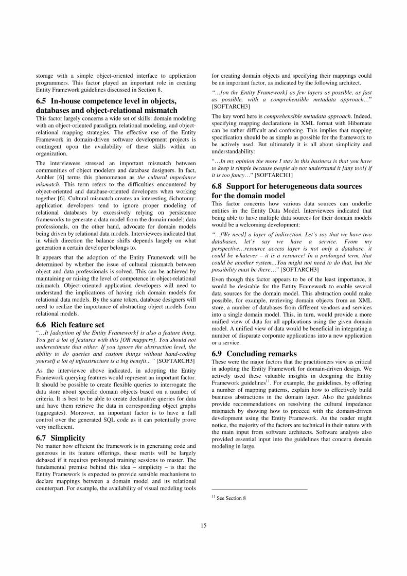
15
storage with a simple object-oriented interface to application
programmers. This factor played an important role in creating
Entity Framework guidelines discussed in Section 8.
6.5 In-house competence level in objects,
databases and object-relational mismatch This factor largely concerns a wide set of skills: domain modeling
with an object-oriented paradigm, relational modeling, and object-
relational mapping strategies. The effective use of the Entity
Framework in domain-driven software development projects is
contingent upon the availability of these skills within an
organization.
The interviewees stressed an important mismatch between
communities of object modelers and database designers. In fact,
Ambler [6] terms this phenomenon as the cultural impedance
mismatch. This term refers to the difficulties encountered by
object-oriented and database-oriented developers when working
together [6]. Cultural mismatch creates an interesting dichotomy:
application developers tend to ignore proper modeling of
relational databases by excessively relying on persistence
frameworks to generate a data model from the domain model; data
professionals, on the other hand, advocate for domain models
being driven by relational data models. Interviewees indicated that
in which direction the balance shifts depends largely on what
generation a certain developer belongs to.
It appears that the adoption of the Entity Framework will be
determined by whether the issue of cultural mismatch between
object and data professionals is solved. This can be achieved by
maintaining or raising the level of competence in object-relational
mismatch. Object-oriented application developers will need to
understand the implications of having rich domain models for
relational data models. By the same token, database designers will
need to realize the importance of abstracting object models from
relational models.
6.6 Rich feature set “…It [adoption of the Entity Framework] is also a feature thing.
You get a lot of features with this [OR mappers]. You should not
underestimate that either. If you ignore the abstraction level, the
ability to do queries and custom things without hand-coding
yourself a lot of infrastructure is a big benefit... ” [SOFTARCH3]
As the interviewee above indicated, in adopting the Entity
Framework querying features would represent an important factor.
It should be possible to create flexible queries to interrogate the
data store about specific domain objects based on a number of
criteria. It is best to be able to create declarative queries for data
and have them retrieve the data in corresponding object graphs
(aggregates). Moreover, an important factor is to have a full
control over the generated SQL code as it can potentially prove
very inefficient.
6.7 Simplicity No matter how efficient the framework is in generating code and
generous in its feature offerings, these merits will be largely
debased if it requires prolonged training sessions to master. The
fundamental premise behind this idea – simplicity – is that the
Entity Framework is expected to provide sensible mechanisms to
declare mappings between a domain model and its relational
counterpart. For example, the availability of visual modeling tools
for creating domain objects and specifying their mappings could
be an important factor, as indicated by the following architect.
“…[on the Entity Framework] as few layers as possible, as fast
as possible, with a comprehensible metadata approach…”
[SOFTARCH3]
The key word here is comprehensible metadata approach. Indeed,
specifying mapping declarations in XML format with Hibernate
can be rather difficult and confusing. This implies that mapping
specification should be as simple as possible for the framework to
be actively used. But ultimately it is all about simplicity and
understandability:
“…In my opinion the more I stay in this business is that you have
to keep it simple because people do not understand it [any tool] if
it is too fancy…” [SOFTARCH1]
6.8 Support for heterogeneous data sources
for the domain model This factor concerns how various data sources can underlie
entities in the Entity Data Model. Interviewees indicated that
being able to have multiple data sources for their domain models
would be a welcoming development:
“…[We need] a layer of indirection. Let’s say that we have two
databases, let’s say we have a service. From my
perspective…resource access layer is not only a database, it
could be whatever – it is a resource! In a prolonged term, that
could be another system…You might not need to do that, but the
possibility must be there…” [SOFTARCH3]
Even though this factor appears to be of the least importance, it
would be desirable for the Entity Framework to enable several
data sources for the domain model. This abstraction could make
possible, for example, retrieving domain objects from an XML
store, a number of databases from different vendors and services
into a single domain model. This, in turn, would provide a more
unified view of data for all applications using the given domain
model. A unified view of data would be beneficial in integrating a
number of disparate corporate applications into a new application
or a service.
6.9 Concluding remarks These were the major factors that the practitioners view as critical
in adopting the Entity Framework for domain-driven design. We
actively used these valuable insights in designing the Entity
Framework guidelines11. For example, the guidelines, by offering
a number of mapping patterns, explain how to effectively build
business abstractions in the domain layer. Also the guidelines
provide recommendations on resolving the cultural impedance
mismatch by showing how to proceed with the domain-driven
development using the Entity Framework. As the reader might
notice, the majority of the factors are technical in their nature with
the main input from software architects. Software analysts also
provided essential input into the guidelines that concern domain
modeling in large.
11 See Section 8
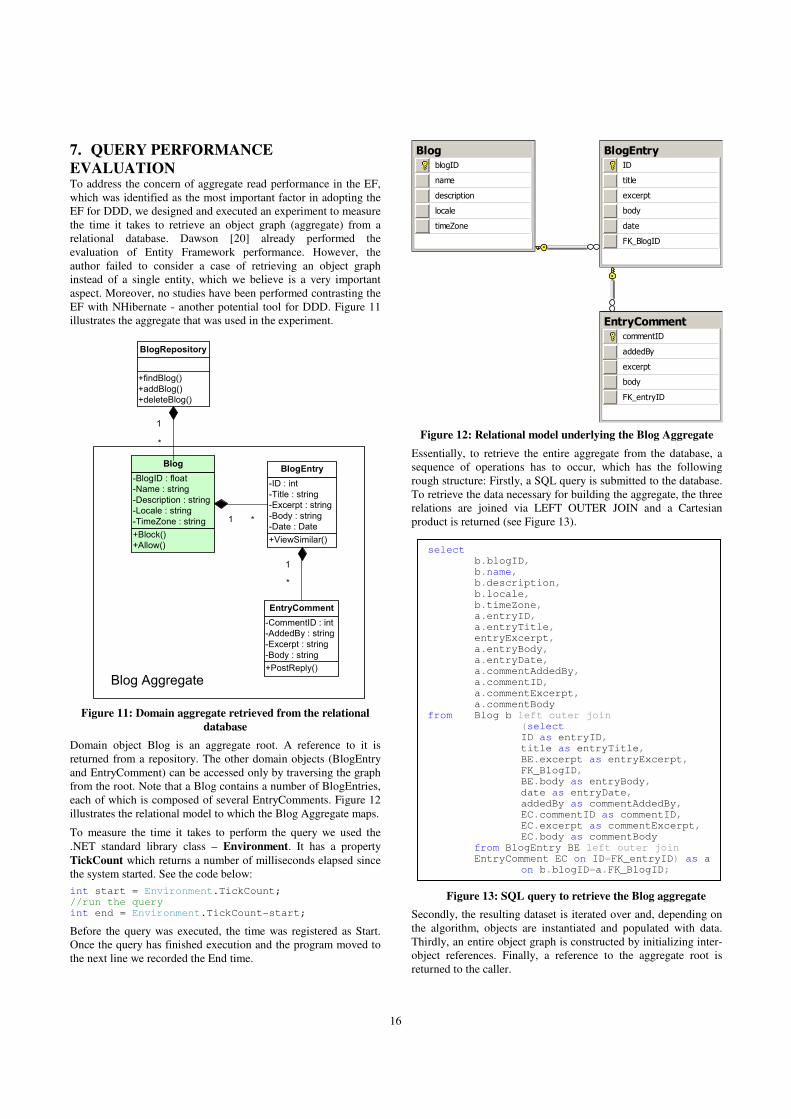
16
7. QUERY PERFORMANCE
EVALUATION To address the concern of aggregate read performance in the EF,
which was identified as the most important factor in adopting the
EF for DDD, we designed and executed an experiment to measure
the time it takes to retrieve an object graph (aggregate) from a
relational database. Dawson [20] already performed the
evaluation of Entity Framework performance. However, the
author failed to consider a case of retrieving an object graph
instead of a single entity, which we believe is a very important
aspect. Moreover, no studies have been performed contrasting the
EF with NHibernate - another potential tool for DDD. Figure 11
illustrates the aggregate that was used in the experiment.
+Block()
+Allow()
-BlogID : float
-Name : string
-Description : string
-Locale : string
-TimeZone : string
Blog
+ViewSimilar()
-ID : int
-Title : string
-Excerpt : string
-Body : string
-Date : Date
BlogEntry
+PostReply()
-CommentID : int
-AddedBy : string
-Excerpt : string
-Body : string
EntryComment
1 *
1
*
Blog Aggregate
+findBlog()
+addBlog()
+deleteBlog()
BlogRepository
1
*
Figure 11: Domain aggregate retrieved from the relational
database
Domain object Blog is an aggregate root. A reference to it is
returned from a repository. The other domain objects (BlogEntry
and EntryComment) can be accessed only by traversing the graph
from the root. Note that a Blog contains a number of BlogEntries,
each of which is composed of several EntryComments. Figure 12
illustrates the relational model to which the Blog Aggregate maps.
To measure the time it takes to perform the query we used the
.NET standard library class – Environment. It has a property
TickCount which returns a number of milliseconds elapsed since
the system started. See the code below:
int start = Environment.TickCount; //run the query int end = Environment.TickCount-start;
Before the query was executed, the time was registered as Start.
Once the query has finished execution and the program moved to
the next line we recorded the End time.
BlogblogID
name
description
locale
timeZone
BlogEntryID
title
excerpt
body
date
FK_BlogID
EntryCommentcommentID
addedBy
excerpt
body
FK_entryID
Figure 12: Relational model underlying the Blog Aggregate
Essentially, to retrieve the entire aggregate from the database, a
sequence of operations has to occur, which has the following
rough structure: Firstly, a SQL query is submitted to the database.
To retrieve the data necessary for building the aggregate, the three
relations are joined via LEFT OUTER JOIN and a Cartesian
product is returned (see Figure 13).
Secondly, the resulting dataset is iterated over and, depending on
the algorithm, objects are instantiated and populated with data.
Thirdly, an entire object graph is constructed by initializing inter-
object references. Finally, a reference to the aggregate root is
returned to the caller.
select b.blogID, b.name, b.description,
b.locale, b.timeZone, a.entryID, a.entryTitle, entryExcerpt, a.entryBody, a.entryDate, a.commentAddedBy, a.commentID,
a.commentExcerpt, a.commentBody
from Blog b left outer join (select
ID as entryID, title as entryTitle, BE.excerpt as entryExcerpt, FK_BlogID, BE.body as entryBody,
date as entryDate, addedBy as commentAddedBy, EC.commentID as commentID, EC.excerpt as commentExcerpt, EC.body as commentBody
from BlogEntry BE left outer join EntryComment EC on ID=FK_entryID) as a
on b.blogID=a.FK_BlogID;
Figure 13: SQL query to retrieve the Blog aggregate
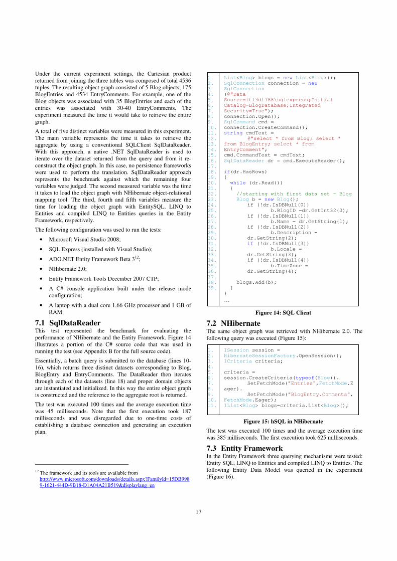
17
Under the current experiment settings, the Cartesian product
returned from joining the three tables was composed of total 4536
tuples. The resulting object graph consisted of 5 Blog objects, 175
BlogEntries and 4534 EntryComments. For example, one of the
Blog objects was associated with 35 BlogEntries and each of the
entries was associated with 30-40 EntryComments. The
experiment measured the time it would take to retrieve the entire
graph.
A total of five distinct variables were measured in this experiment.
The main variable represents the time it takes to retrieve the
aggregate by using a conventional SQLClient SqlDataReader.
With this approach, a native .NET SqlDataReader is used to
iterate over the dataset returned from the query and from it re-
construct the object graph. In this case, no persistence frameworks
were used to perform the translation. SqlDataReader approach
represents the benchmark against which the remaining four
variables were judged. The second measured variable was the time
it takes to load the object graph with NHibernate object-relational
mapping tool. The third, fourth and fifth variables measure the
time for loading the object graph with EntitySQL, LINQ to
Entities and compiled LINQ to Entities queries in the Entity
Framework, respectively.
The following configuration was used to run the tests:
• Microsoft Visual Studio 2008;
• SQL Express (installed with Visual Studio);
• ADO.NET Entity Framework Beta 312;
• NHibernate 2.0;
• Entity Framework Tools December 2007 CTP;
• A C# console application built under the release mode
configuration;
• A laptop with a dual core 1.66 GHz processor and 1 GB of
RAM.
7.1 SqlDataReader This test represented the benchmark for evaluating the
performance of NHibernate and the Entity Framework. Figure 14
illustrates a portion of the C# source code that was used in
running the test (see Appendix B for the full source code).
Essentially, a batch query is submitted to the database (lines 10-
16), which returns three distinct datasets corresponding to Blog,
BlogEntry and EntryComments. The DataReader then iterates
through each of the datasets (line 18) and proper domain objects
are instantiated and initialized. In this way the entire object graph
is constructed and the reference to the aggregate root is returned.
The test was executed 100 times and the average execution time
was 45 milliseconds. Note that the first execution took 187
milliseconds and was disregarded due to one-time costs of
establishing a database connection and generating an execution
plan.
12 The framework and its tools are available from
http://www.microsoft.com/downloads/details.aspx?FamilyId=15DB998
9-1621-444D-9B18-D1A04A21B519&displaylang=en
7.2 NHibernate The same object graph was retrieved with NHibernate 2.0. The
following query was executed (Figure 15):
The test was executed 100 times and the average execution time
was 385 milliseconds. The first execution took 625 milliseconds.
7.3 Entity Framework In the Entity Framework three querying mechanisms were tested:
Entity SQL, LINQ to Entities and compiled LINQ to Entities. The
following Entity Data Model was queried in the experiment
(Figure 16).
List<Blog> blogs = new List<Blog>(); SqlConnection connection = new SqlConnection (@"Data Source=itl3df788\sqlexpress;Initial Catalog=BlogDatabase;Integrated
Security=True"); connection.Open(); SqlCommand cmd = connection.CreateCommand(); string cmdText = @"select * from Blog; select * from BlogEntry; select * from EntryComment"; cmd.CommandText = cmdText;
SqlDataReader dr = cmd.ExecuteReader(); if(dr.HasRows) { while (dr.Read()) { //starting with first data set - Blog Blog b = new Blog();
if (!dr.IsDBNull(0))
b.BlogID =dr.GetInt32(0); if (!dr.IsDBNull(1))
b.Name = dr.GetString(1); if (!dr.IsDBNull(2))
b.Description = dr.GetString(2);
if (!dr.IsDBNull(3)) b.Locale =
dr.GetString(3); if (!dr.IsDBNull(4))
b.TimeZone = dr.GetString(4);
blogs.Add(b); } }
…
Figure 14: SQL Client
1. 2. 3. 4. 5. 6.
7. 8. 9. 10. 11. 12. 13. 14. 15.
16. 17. 18. 19. 20. 21. 22. 23. 24. 25.
26. 27. 28. 29. 30. 31. 32. 33. 34.
35. 36. 37. 38. 39.
ISession session = HibernateSessionFactory.OpenSession(); ICriteria criteria; criteria = session.CreateCriteria(typeof(Blog)).
SetFetchMode("Entries",FetchMode.Eager).
SetFetchMode("BlogEntry.Comments",FetchMode.Eager); IList<Blog> blogs=criteria.List<Blog>();
1. 2. 3. 4. 5. 6. 7. 8.
9. 10. 11.
Figure 15: hSQL in NHibernate

18
Figure 16: The Entity Data Model generated from the Blog
relational model
7.3.1 Entity SQL Entity SQL represents one of the main querying mechanisms in
the Entity Framework. The following query was executed to
retrieve the object graph:
using (BlogDatabaseEntities objModel = new BlogDatabaseEntities()) { ObjectQuery<Blog> blogs = objModel.Blog.Include
("BlogEntry.EntryComment"); blogs.Execute(MergeOption.OverwriteChanges);
}
The query was executed 100 times and the average execution time
was 350 milliseconds. The first execution took some 828 seconds.
This was due to a number of operations that the Entity Framework
performed, such as view generation, metadata initialization and
others. See Dawson [20] for a detailed explanation of the
initialization process.
7.3.2 LINQ to Entities LINQ to Entities represents a strongly-typed LINQ-based query
language integrated into C# programming language. The
following query was executed:
var blogsQuery = from blog in objModel.Blog select new { Blog=blog, Entry=blog.BlogEntry,
Comment=(from entry in blog.BlogEntry select new {Comment=entry.EntryComment})};
Note how the LINQ query differs from the SQL query. Instead of
operating on relations and joins based on foreign keys, the query
operates on domain objects and their associations. Moreover, the
query is more expressive and far less verbose. The test was
executed 100 times and the average execution time was 360
milliseconds. The first execution took 1062 milliseconds.
7.3.3 Compiled LINQ to Entities A compiled LINQ query differs from its non-compiled
counterpart in that on its first run the query execution tree is built
and cached. On subsequent executions the execution tree is
reused, which in theory should improve performance. The
following compiled query was executed (figure 17).
Figure 17: Compiled LINQ to Entities query
Like all previous tests, this query was executed 100 times and the
average execution time was 336 milliseconds. The first execution
took 1032 milliseconds.
7.4 Analysis Interestingly, the read performance of the two persistence
frameworks does not even remotely match the performance of the
regular SqlDataReader. SqlDataReader may thus seem as a viable
option to create the data access layer. However, for large systems,
writing custom mapping infrastructure could represent an
intimidating task. According to Keene [28], building and
configuring object/relational data access could account for some
30-40% of total project effort.
At the same time, the Entity Framework appears to perform well
compared to NHibernate. In fact, the performance of its three
querying mechanisms is slightly better than that of NHibernate.
This could be explained by different caching strategies employed
by the EF. However, on the average, the costs associated with the
first-time initialization in the EF appear to be higher than those of
NHibernate. In the EF the first execution took from 828 to
upwards 3045 milliseconds. The first execution time in
NHibernate was relatively stable at 625 milliseconds. Yet, during
subsequent query executions, the EF performed better than
NHibernate (see Figure 18). Dawson [20] argues that high
initialization costs in the EF are mainly caused by the run-time
view generation – creating SQL views based on the specified
mappings. According to him, some 56% of the first-time
execution time is expended on generating entity-relation views.
This step can be avoided by generating views at compile-time. As
a result, Dawson continues, the first-time execution can be
decreased by 28%.
var compiledQuery = CompiledQuery.Compile( (BlogDatabaseEntities context) => from blog
in context.Blog select new {
Blog = blog, Entry = blog.BlogEntry, Comment = (from entry in blog.BlogEntry select new { Comment = entry.EntryComment })
}); using (BlogDatabaseEntities objModel = new BlogDatabaseEntities()) {
var blogsQuery = compiledQuery.Invoke(objModel);
}
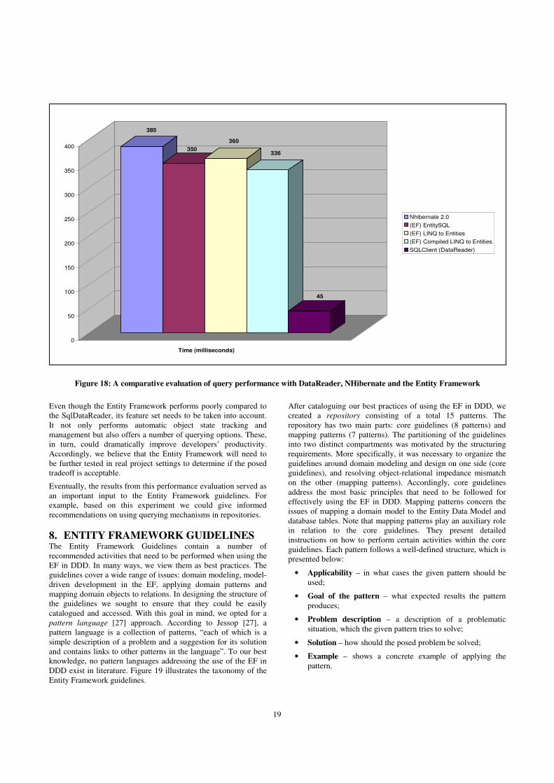
19
Figure 18: A comparative evaluation of query performance with DataReader, NHibernate and the Entity Framework
Even though the Entity Framework performs poorly compared to
the SqlDataReader, its feature set needs to be taken into account.
It not only performs automatic object state tracking and
management but also offers a number of querying options. These,
in turn, could dramatically improve developers’ productivity.
Accordingly, we believe that the Entity Framework will need to
be further tested in real project settings to determine if the posed
tradeoff is acceptable.
Eventually, the results from this performance evaluation served as
an important input to the Entity Framework guidelines. For
example, based on this experiment we could give informed
recommendations on using querying mechanisms in repositories.
8. ENTITY FRAMEWORK GUIDELINES The Entity Framework Guidelines contain a number of
recommended activities that need to be performed when using the
EF in DDD. In many ways, we view them as best practices. The
guidelines cover a wide range of issues: domain modeling, model-
driven development in the EF, applying domain patterns and
mapping domain objects to relations. In designing the structure of
the guidelines we sought to ensure that they could be easily
catalogued and accessed. With this goal in mind, we opted for a
pattern language [27] approach. According to Jessop [27], a
pattern language is a collection of patterns, “each of which is a
simple description of a problem and a suggestion for its solution
and contains links to other patterns in the language”. To our best
knowledge, no pattern languages addressing the use of the EF in
DDD exist in literature. Figure 19 illustrates the taxonomy of the
Entity Framework guidelines.
After cataloguing our best practices of using the EF in DDD, we
created a repository consisting of a total 15 patterns. The
repository has two main parts: core guidelines (8 patterns) and
mapping patterns (7 patterns). The partitioning of the guidelines
into two distinct compartments was motivated by the structuring
requirements. More specifically, it was necessary to organize the
guidelines around domain modeling and design on one side (core
guidelines), and resolving object-relational impedance mismatch
on the other (mapping patterns). Accordingly, core guidelines
address the most basic principles that need to be followed for
effectively using the EF in DDD. Mapping patterns concern the
issues of mapping a domain model to the Entity Data Model and
database tables. Note that mapping patterns play an auxiliary role
in relation to the core guidelines. They present detailed
instructions on how to perform certain activities within the core
guidelines. Each pattern follows a well-defined structure, which is
presented below:
• Applicability – in what cases the given pattern should be
used;
• Goal of the pattern – what expected results the pattern
produces;
• Problem description – a description of a problematic
situation, which the given pattern tries to solve;
• Solution – how should the posed problem be solved;
• Example – shows a concrete example of applying the
pattern.
385
350
360
336
45
0
50
100
150
200
250
300
350
400
Nhibernate 2.0
(EF) EntitySQL
(EF) LINQ to Entities
(EF) Compiled LINQ to Entities
SQLClient (DataReader)
Time (milliseconds)

20
Figure 19: Taxonomy of the Entity Framework Guidelines
Essentially, we see this structure as the language of a pattern. It
serves as a common language for defining a pattern, which could
potentially allow a broader range of people within Volvo IT to
consume patterns and contribute new ones, thus increasing the
overall knowledge base in the domain-driven design. Eventually,
this language was used to develop all the Entity Framework
guidelines, which were then presented to the Software Process
Improvement Group at Volvo IT. The guidelines were presented
in the context of a real-world sample domain-driven application:
the guidelines show how to proceed with the DDD, beginning
from initial domain modeling and ending with the implementation
of a portion of a DDD application supported by the EF. The
following sub-sections discuss the pattern discovery process and
present an overview of the guidelines, which are the main result of
this Master thesis. The details of the guidelines are a proprietary
asset of Volvo IT and cannot be published according to our
confidentiality agreements.
8.1 Pattern discovery process The main goal of the discovery process was to capture ‘hidden’
organizational knowledge about domain modeling and design, and
document it in the form of a structured description of a solution to
a recurring problem. In this way, we sought to make implicit
(tacit) knowledge within Volvo IT explicit and universally
accessible to all employees within the organization. To achieve
this and catalogue a collection of patterns, we interviewed
software architects and systems analysts on such topics as domain
modeling, object-relational mismatch and object persistence. For
example, an architect was interviewed about domain-driven
design in his projects. Then, his suggestions for incorporating
DDD into a software development process or domain modeling in
general were used in formulating guidelines 1 and 2. In the same
manner, systems analysts contributed to these two guidelines.
Some other guidelines (GL3, 5 and 6, for example) were elicited
from studying available literature on the topic and then validated
with the senior .NET architect. Also, jointly with this architect all
mapping patterns were identified.
8.2 Core guidelines
8.2.1 GL 1: Business domain modeling As opposed to the database-driven design, the designers should
already at the domain modeling stage use object-oriented
constructs (such as inheritance) rather than database-related
constructs (i.e. constructs that can be readily stored in the
database). This guideline ensures that an object-oriented domain
model captures domain concepts and their relationships in a more
precise way than do database-oriented object models. Essentially,
it offers guidance on collecting knowledge about a domain from
domain experts and distilling it in a model. It shows when in a
generic software development process at Volvo IT domain
modeling should take place. This guideline is largely based on
recommendations made by Evans [22], but it also offers advice
based on knowledge gained during interviews with systems
analysts. We view this guideline to be one of the focal ones as it
addresses primary issues raised by interviewees:
“…The biggest value of a domain model is that you have a
common language and you have a base for…[application]
architecture…If you know the domain, how concepts are related
to each other, you can reflect this in the architecture of the
software. And then you do better software…” [SOFTARCH1]
8.2.2 GL 2: Capturing domain logic A central characteristic of a domain model is that it not only
captures essential business concepts but also provides a
mechanism for structuring domain logic. This guideline addresses
the issue of capturing domain logic and illustrates how the process
should be organized. It was largely informed by software
architects and complemented by the work of some authors [22,
25]. Essentially, the guideline is about what domain logic should
be modeled in entities and what logic should be modeled as
services, for example. This guideline was largely inspired by a
software architect interviewed during the study:
“…business rules are very important…If you don’t think about
business rules and just go ahead and specify your use cases, you
will have serious problems because business rules are normally
quite complex and they are not flows like use cases…When you do
use cases, you have to be aware that you have business
rules…”[SOFTARCH1]
8.2.3 GL 3: Expressing domain model in software Once the domain model has been produced, it is necessary to
make it explicit in software: transform it into its software
representation. This guideline shows how to express a domain
model with the Entity Framework and make the model executable.
The guideline addresses a number of issues in performing

21
mappings of different domain model constructs to their software
peers.
8.2.4 GL 4: Validating the domain model Once the first versions of a domain model have been released in
the project, it is critical to perform the validation of a model with
domain experts. This is explained by the need to ensure that the
domain model accurately captures important domain concepts,
their relationship and essential business rules. This guideline
shows how to effectively perform validation of a domain model
with the Entity Framework.
8.2.5 GL 5: Applying the Aggregate pattern This guideline shows how to apply the Aggregate pattern within
the Entity Framework. Such important issues are considered as:
the choice of a query language for retrieving aggregates, aggregate
boundary definition, implementing aggregates within the EDM
and others. The guideline actively uses the results from evaluating
performance of the EF querying mechanisms.
8.2.6 GL 6: Applying the Repository pattern The repository is an abstraction over a domain model. It
represents an object-oriented collection of domain objects: an in-
memory object database. This guideline discusses how Entity
Framework features can be leveraged for creating an effective
mechanism for managing domain objects in an application. Such
issues are considered as: managing ObjectServices context,
defining and building proper transactions and others. Moreover,
this guideline addresses the problems of defining Factories for
creating domain aggregates with the Entity Framework. Finally,
this guideline discusses the creation of services that consume
domain objects from the repository. In this context, the guideline
provides recommendations in scoping and creating transactions.
Also, strategies for preventing optimistic concurrency violations
are addressed in this guideline.
8.2.7 GL 7: Reverse engineering It is likely that a new object-oriented application will need to be
built on an existing legacy database. In such a project it may be
the case that no documentation will exist short for the legacy data
model. Therefore, considering that object-oriented languages are
best suited for operating on concepts, it becomes essential to be
able to effectively reverse-engineer the legacy database and
extract important concepts from its relational model. This
guideline shows how the Entity Framework should be used for
reverse engineering existing databases and, subsequently,
migrating these systems to domain-driven design practices. For
example, the guideline shows how to:
• extract inheritance structures from a relational model;
• extract aggregation/composition relationships;
• extract associations of different cardinalities, especially
many-to-many associations;
8.2.8 GL 8: Implementing business rules in the
Entity Framework An essential characteristic of a domain model is that business
logic is embedded directly into domain objects. However, the
EDM is only a data model: it is impossible to specify business
rules in this model. We need to find a way of encapsulating
business logic in domain objects. This guideline discusses
different possibilities of implementing domain logic in domain
objects generated by the Entity Framework.
8.3 Mapping patterns Mapping patterns complement the core guidelines with the
detailed guidance on mapping a domain model to the Entity Data
Model and then mapping the latter to a relational database model.
We identified a set of 7 major patterns. Possibly, many more may
exist, but the current seven, we believe, represent the most
common cases in domain modeling. The catalogue of patterns was
identified and validated by the senior .NET architect. The details
of some mapping patterns were also informed by [7, 25, 29].
Some mapping patterns are accompanied by a discussion of
implications (consequences) of applying it for maintainability and
performance attributes.
8.3.1 Pattern: Object Association Object association represents the fact that one object is in some
way related to another (see Figure 20). This pattern describes the
process of mapping object associations to the EDM constructs and
database tables. The pattern considers the following multiplicities:
one-to-one, one-to-many and many-to – many.
Figure 20: Object association
8.3.2 Pattern: Object Aggregation Object aggregation shows that one object (aggregate) consists of
some other object(s) (see Figure 21). This is a so-called “has-a”
relationship. Object Aggregation pattern shows the options for
mapping aggregation to the EDM constructs and subsequently to
database tables.
Figure 21: Object aggregation
8.3.3 Pattern: Object Composition Object composition is stronger than aggregation in that the
composite determines the life of its components. That is, should
the composite be destroyed, all of its components will also be
destroyed (see figure 22). This pattern shows how to ensure
composite behavior in both the EDM and the relational model.
Figure 22: Object composition
8.3.4 Pattern: Object Self-Association Self-association occurs when a class maintains a reference to
itself. More specifically, an object would refer to a subset of
objects of the same class. Consider figure 23.
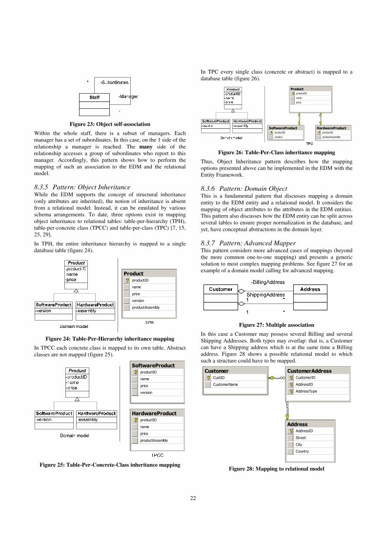
22
Figure 23: Object self-association
Within the whole staff, there is a subset of managers. Each
manager has a set of subordinates. In this case, on the 1 side of the
relationship a manager is reached. The many side of the
relationship accesses a group of subordinates who report to this
manager. Accordingly, this pattern shows how to perform the
mapping of such an association to the EDM and the relational
model.
8.3.5 Pattern: Object Inheritance While the EDM supports the concept of structural inheritance
(only attributes are inherited), the notion of inheritance is absent
from a relational model. Instead, it can be emulated by various
schema arrangements. To date, three options exist in mapping
object inheritance to relational tables: table-per-hierarchy (TPH),
table-per-concrete class (TPCC) and table-per-class (TPC) [7, 15,
25, 29].
In TPH, the entire inheritance hierarchy is mapped to a single
database table (figure 24).
Product
productID
name
price
version
productAssembly
Figure 24: Table-Per-Hierarchy inheritance mapping
In TPCC each concrete class is mapped to its own table. Abstract
classes are not mapped (figure 25).
HardwareProductproductID
name
price
productAssembly
SoftwareProduct
productID
name
price
version
Figure 25: Table-Per-Concrete-Class inheritance mapping
In TPC every single class (concrete or abstract) is mapped to a
database table (figure 26).
SoftwareProduct
productID
version
HardwareProduct
productID
productAssembly
Product
productID
name
price
Figure 26: Table-Per-Class inheritance mapping
Thus, Object Inheritance pattern describes how the mapping
options presented above can be implemented in the EDM with the
Entity Framework.
8.3.6 Pattern: Domain Object This is a fundamental pattern that discusses mapping a domain
entity to the EDM entity and a relational model. It considers the
mapping of object attributes to the attributes in the EDM entities.
This pattern also discusses how the EDM entity can be split across
several tables to ensure proper normalization in the database, and
yet, have conceptual abstractions in the domain layer.
8.3.7 Pattern: Advanced Mapper This pattern considers more advanced cases of mappings (beyond
the more common one-to-one mapping) and presents a generic
solution to most complex mapping problems. See figure 27 for an
example of a domain model calling for advanced mapping.
Figure 27: Multiple association
In this case a Customer may possess several Billing and several
Shipping Addresses. Both types may overlap: that is, a Customer
can have a Shipping address which is at the same time a Billing
address. Figure 28 shows a possible relational model to which
such a structure could have to be mapped.
AddressAddressID
Street
City
Country
Customer
CustID
CustomerName
CustomerAddress
CustomerID
AddressID
AddressType
Figure 28: Mapping to relational model

23
In this model, an association table is created which not only
connects customer to addresses but also stores the role a certain
connection plays – AddressType (Billing or Shipping). Mapping
such models to a domain model presented in figure 27 requires
more advanced techniques that go beyond simpler mappings in
the Entity Framework designer. Exactly these situations are
addressed by the Advanced Mapper pattern.
8.3.8 Mapping pattern example Pattern: Object Association
Applicability
This pattern applies to mapping associations in a domain model.
Goal of the pattern
The pattern shows how to map different types of object
associations to the EDM inter-entity associations and database
tables.
Problem description
How should a one-to-many object association be mapped to the
EDM entity relationship?
Solution
Map one-to-many association to an entity association with the
same multiplicity characteristics. This is possible because EDM
associations are inherently weak, which means that the destruction
of an object does not necessarily lead to the destruction of a
related object.
To map the resulting structure to database tables perform the
following: Create a table for each EDM entity. The keys and
attributes from the EDM remain the same in the database tables.
Add a foreign key to the table that represents the EDM entity on
the many side of the association. The foreign key is the key from
the entity on the one side of the association.
Example
Consider a portion of a domain model below:
This model denotes that an Employee may possess a number of
various Skills. How should we approach mapping this model to
the EDM and the relational database model? Firstly, this model is
mapped to the EDM constructs. By applying one-to-one mapping
between the domain model and the EDM and using a weak
association we can derive the following model:
Then map the resulting EDM model to the following relational
structure:
EmployeeSSN
fName
lName
salary
hiringDate
SkillskillID
skillTitle
skillDescription
employee_FK
The entities are mapped one-to-one to database tables. The keys
from the entities in the EDM remain the same in the tables. Note
the addition of a foreign key to Skill table denoting the one-to-
many relationship from Employee table to Skill table.
9. DISCUSSION
9.1 Why patterns? We decided to present the guidelines with a pattern approach for a
number of reasons. First and foremost, an individual pattern is
focused on one and only one specific problem/solution pair at a
time. A pattern does not attempt to address numerous issues
simultaneously; rather, it tackles a single problem in an isolated
fashion. Fowler [24] refers to such approach as encapsulating the
problem and states that it is instrumental in solving design
problems in such a massive topic as software. A pattern is very
specific in showing solutions to a concrete problem. Alternatively,
we could formulate the guidelines in the form of general
principles. However, principles are often too abstract and may not
lend themselves well to specific problematic situations in using
the Entity Framework. For example, consider a case of mapping
an abstract conceptual model to a relational model. Unless
mapping is performed by a highly experienced developer (in
which case he does not really need any patterns: he knows the
solutions already), documented best practice will be required for
the less skilled developers to perform effective mapping.
Second, patterns are defined by a language, which imposes a
standard structure on them. With a well-defined structure patterns
can be catalogued and accessed more easily. Considering that a
pattern explicitly states in which context it is applicable, it should
be a more straightforward process finding an appropriate solution
to the given problem.
Finally, a catalogue of patterns is the knowledge base of an
organization. Fowler [24] offers a relevant discussion of the value
of ‘patternizing’ organizational knowledge. The fundamental
irony of patterns is that they, by definition, do not offer anything
new. Rather, they capture what has already been known
(implicitly or explicitly) in a structured description. In fact, they
may even seem trivial to experts in the field. One could argue that
this debases the value of patterns. However, one should also
consider that there are less skilled individuals who are only now
beginning to master the field and they need to gain access to
experts’ knowledge. And here lies the primary benefit of
cataloguing patterns: they help disseminate expert knowledge
within an organization.
9.2 Initial evaluation To assess whether the pattern approach to presenting guidelines
made sense, we conducted a joint evaluation workshop with the
software architects and analysts (referred to as evaluators in this
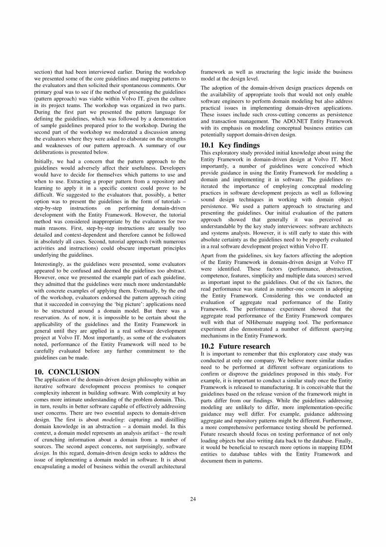
24
section) that had been interviewed earlier. During the workshop
we presented some of the core guidelines and mapping patterns to
the evaluators and then solicited their spontaneous comments. Our
primary goal was to see if the method of presenting the guidelines
(pattern approach) was viable within Volvo IT, given the culture
in its project teams. The workshop was organized in two parts.
During the first part we presented the pattern language for
defining the guidelines, which was followed by a demonstration
of sample guidelines prepared prior to the workshop. During the
second part of the workshop we moderated a discussion among
the evaluators where they were asked to elaborate on the strengths
and weaknesses of our pattern approach. A summary of our
deliberations is presented below.
Initially, we had a concern that the pattern approach to the
guidelines would adversely affect their usefulness. Developers
would have to decide for themselves which patterns to use and
when to use. Extracting a proper pattern from a repository and
learning to apply it in a specific context could prove to be
difficult. We suggested to the evaluators that, possibly, a better
option was to present the guidelines in the form of tutorials –
step-by-step instructions on performing domain-driven
development with the Entity Framework. However, the tutorial
method was considered inappropriate by the evaluators for two
main reasons. First, step-by-step instructions are usually too
detailed and context-dependent and therefore cannot be followed
in absolutely all cases. Second, tutorial approach (with numerous
activities and instructions) could obscure important principles
underlying the guidelines.
Interestingly, as the guidelines were presented, some evaluators
appeared to be confused and deemed the guidelines too abstract.
However, once we presented the example part of each guideline,
they admitted that the guidelines were much more understandable
with concrete examples of applying them. Eventually, by the end
of the workshop, evaluators endorsed the pattern approach citing
that it succeeded in conveying the ‘big picture’: applications need
to be structured around a domain model. But there was a
reservation. As of now, it is impossible to be certain about the
applicability of the guidelines and the Entity Framework in
general until they are applied in a real software development
project at Volvo IT. Most importantly, as some of the evaluators
noted, performance of the Entity Framework will need to be
carefully evaluated before any further commitment to the
guidelines can be made.
10. CONCLUSION The application of the domain-driven design philosophy within an
iterative software development process promises to conquer
complexity inherent in building software. With complexity at bay
comes more intimate understanding of the problem domain. This,
in turn, results in better software capable of effectively addressing
user concerns. There are two essential aspects to domain-driven
design. The first is about modeling: capturing and distilling
domain knowledge in an abstraction – a domain model. In this
context, a domain model represents an analysis artifact – the result
of crunching information about a domain from a number of
sources. The second aspect concerns, not surprisingly, software
design. In this regard, domain-driven design seeks to address the
issue of implementing a domain model in software. It is about
encapsulating a model of business within the overall architectural
framework as well as structuring the logic inside the business
model at the design level.
The adoption of the domain-driven design practices depends on
the availability of appropriate tools that would not only enable
software engineers to perform domain modeling but also address
practical issues in implementing domain-driven applications.
These issues include such cross-cutting concerns as persistence
and transaction management. The ADO.NET Entity Framework
with its emphasis on modeling conceptual business entities can
potentially support domain-driven design.
10.1 Key findings This exploratory study provided initial knowledge about using the
Entity Framework in domain-driven design at Volvo IT. Most
importantly, a number of guidelines were conceived which
provide guidance in using the Entity Framework for modeling a
domain and implementing it in software. The guidelines re-
iterated the importance of employing conceptual modeling
practices in software development projects as well as following
sound design techniques in working with domain object
persistence. We used a pattern approach to structuring and
presenting the guidelines. Our initial evaluation of the pattern
approach showed that generally it was perceived as
understandable by the key study interviewees: software architects
and systems analysts. However, it is still early to state this with
absolute certainty as the guidelines need to be properly evaluated
in a real software development project within Volvo IT.
Apart from the guidelines, six key factors affecting the adoption
of the Entity Framework in domain-driven design at Volvo IT
were identified. These factors (performance, abstraction,
competence, features, simplicity and multiple data sources) served
as important input to the guidelines. Out of the six factors, the
read performance was stated as number-one concern in adopting
the Entity Framework. Considering this we conducted an
evaluation of aggregate read performance of the Entity
Framework. The performance experiment showed that the
aggregate read performance of the Entity Framework compares
well with that of NHibernate mapping tool. The performance
experiment also demonstrated a number of different querying
mechanisms in the Entity Framework.
10.2 Future research It is important to remember that this exploratory case study was
conducted at only one company. We believe more similar studies
need to be performed at different software organizations to
confirm or disprove the guidelines proposed in this study. For
example, it is important to conduct a similar study once the Entity
Framework is released to manufacturing. It is conceivable that the
guidelines based on the release version of the framework might in
parts differ from our findings. While the guidelines addressing
modeling are unlikely to differ, more implementation-specific
guidance may well differ. For example, guidance addressing
aggregate and repository patterns might be different. Furthermore,
a more comprehensive performance testing should be performed.
Future research should focus on testing performance of not only
loading objects but also writing data back to the database. Finally,
it would be beneficial to research more options in mapping EDM
entities to database tables with the Entity Framework and
document them in patterns.

25
11. ACKNOWLEDGMENTS This Master thesis has been an outstanding exercise in knowledge
discovery, which would have been impossible without:
The Swedish Institute, whose kind support in cultural and
monetary aspects has kept me going throughout my whole stay in
Sweden. I would like to thank the Swedish Institute for granting
me a scholarship to pursue my studies at the IT University.
Miroslaw Staron – Software Engineering and Management
program manager at the IT University, who was an academic
supervisor of mine. Miroslaw provided valuable guidance in
tackling the study most effectively. I would like to thank him for
his patience, understanding and, most importantly, objective
criticism of my work.
Ludwik Wallin – an architect at Volvo Information Technology,
who was an industrial supervisor of mine. Ludwik provided a
valuable insight into issues concerning building enterprise
software and also guided me towards relevant aspects of the
Entity Framework and domain-driven design that need be
carefully studied. I would also like to thank all employees from
the Software Process Improvement group and other departments
at Volvo IT who contributed to this study with important
interviews and informal discussions.
Thanks again to all of you for your help, time and willingness to
share experience and insightful comments!
12. REFERENCES 1. MDA Guide Version 1.0.1. 2003: OMG.
2. Microsoft simplifies data-centric development in
heterogeneous IT environment. 2007 [cited 24/04/08];
Available from:
http://www.microsoft.com/presspass/press/2007/dec07/12-
06EntityBeta3PR.mspx.
3. (2001) Rational Unified Process: Best Practices for
Software Development Teams. A Rational Software
Corporation White Paper Volume,
4. Adya, A., Blakeley, J., Melnik, S., Muralidhar, S., Anatomy
of the ADO.NET Entity Framework. Proceedings of the
2007 ACM SIGMOD International Conference of
Management of Data, 2007: p. 877-888.
5. Al-Mansari, M., Hanenberg, S., Unland, R., Orthogonal
Persistence and AOP: A Balancing Act. ACM Workshop
ACP4IS, 2007.
6. Ambler, S., Agile Database Techniques: Effective Strategies
for the Agile Software Developer. 2003: Wiley Publishing.
7. Ambler, S. Mapping Objects to Relational Databases: O/R
Mapping in Detail. [cited 23/04/08]; Available from:
http://www.agiledata.org/essays/mappingObjects.html.
8. Anda, B., Sjoberg, D., Investigating the Role of Use Cases
in the Construction of Class Diagrams. Empirical Software
Engineering, 2005. 10: p. 285-309.
9. Bernsten, K., Sampson, J., Osterlie, T., Interpretive
research methods in computer science. Norwegian
University of Science and Technology, 2004.
10. Bittner, K., Spence, I., Use Case Modeling. 2002: Addison-
Wesley. 368.
11. Blakeley, J., Muralidhar, S., Nori, A., The ADO.NET Entity
Framework: Making the Conceptual Level Real. SIGMOD,
2006. 4(35).
12. Bläser, L., A Programming Language with Natural
Persistence. ACM OOPSLA, 2006.
13. Booch, G., Rumbaugh, J., Jacobson, I., The Unified
Modeliling Language User Guide. 2005: Addison-Wesley.
14. Brdjanin, D., Maric, S., An Example of Use-Case-driven
Conceptual Design of Relational Database. EUROCON,
2007. The International Conference on "Computer as a
Tool", 2007: p. 538-545.
15. Brown, K., Whitenack, B., Crossing Chasms: A Pattern
Language for Object-RDBMS Integration. Pattern
Languages of Program Design, ACM, 1996: p. 227-238.
16. Castro, P., Melnik, S., Adya, A., The ADO.NET Entity
Framework: Raising the Level of Abstraction in Data
Programming. SIGMOD'07, 2007.
17. Chen, P., The entity-relationship model - toward a unified
view of data. ACM Trans. Database Systems, 1976. 1(1).
18. Cook, W., Ibrahim, A., Integrating Programming
Languages and Databases: What's the Problem?
Department of Computer Sciences, University of Texas at
Austin, 2005.
19. Crain, A. The Simple Artifacts of Analysis and Design.
2004 [cited 23/04/08]; Available from:
http://www.ibm.com/developerworks/rational/library/4871.h
tml.
20. Dawson, B. ADO.NET Entity Framework Performance
Comparison. 2008 [cited 05/05/08]; Available from:
http://blogs.msdn.com/adonet/archive/2008/03/27/ado-net-
entity-framework-performance-comparison.aspx.
21. Easterbrook, S., Yu, E., Aranda, J., Fan, Y., Horkoff, J.,
Leica, M., Qadir, R., Do Viewpoints Lead to Better
Conceptual Models? An Exploratory Case Study. 13th IEEE
International Conference on Requirements Engineering,
2005: p. 199-208.
22. Evans, E., Domain-Driven Design: Tackling Complexity in
the Heart of Software. 2004: Addison-Wesley.
23. Fowler, M. Anemic Domain Model. 2003 [cited 05/05/08];
Available from:
http://martinfowler.com/bliki/AnemicDomainModel.html.
24. Fowler, M., Patterns. Software, IEEE, 2003. 20(2): p. 56-
57.
25. Fowler, M., Patterns of Enterprise Application
Architecture. 2002: Addison Wesley.
26. Haan, J.d. MDA, Model Driven Architecture basic concepts.
2008 [cited 21/04/08]; Available from:
http://www.theenterprisearchitect.eu/archive/2008/01/16/md
a_model_driven_architecture_.
27. Jessop, A., Pattern language: A framework for learning.
European Journal of Operational Research, 2004(153): p.
457-465.
28. Keene, K., Data Services for Next Generation SOAs. SOA
WebServices Journal, 2004. 4(12).
29. Keller, W., Mapping objects to Tables: A Pattern
Language. Proceedings of European Conference of Pattern
Languages of Programming Conference'97, 1997.
30. Landre, E., Wesenberg, H., Olmheim, J., Agile Enterprise
Software Development Using Domain-Driven Design and
Test First. Companion to the 22nd ACM SIGPLAN
Conference on Object Oriented Programming Systems and
Applications COmpanion, 2007: p. 983-993.
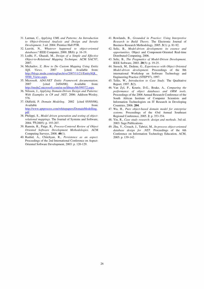
26
31. Larman, C., Applying UML and Patterns: An Introduction
to Object-Oriented Analysis and Design and Iteratie
Development. 3 ed. 2004: Prentice Hall PTR.
32. Leavitt, N., Whatever happened to object-oriented
databases? IEEE Computer, 2000. 33(8): p. 16-19.
33. Lodhi, F., Ghazali, M., Design of a Simple and Effective
Object-to-Relational Mapping Technique. ACM SAC'07,
2007.
34. Michailov, Z. How to Do Custom Mapping Using Entity
SQL Views. 2007 [cited; Available from:
http://blogs.msdn.com/esql/archive/2007/11/21/EntitySQL_
5F00_Views.aspx.
35. Microsoft. ADO.NET Entity Framework documentation.
2007 [cited 24/04/08]; Available from:
http://msdn2.microsoft.com/en-us/library/bb399572.aspx.
36. Nilsson, J., Applying Domain-Driven Design and Patterns:
With Examples in C# and .NET. 2006: Addison-Wesley.
576.
37. Oldfield, P. Domain Modeling. 2002 [cited 05/05/08];
Available from:
http://www.aptprocess.com/whitepapers/DomainModelling.
pdf.
38. Philippi, S., Model driven generation and testing of object-
relational mappings. The Journal of Systems and Software,
2004. 77(2005): p. 193-207.
39. Ramsin, R., Paige, R., Process-Centered Review of Object
Oriented Software Development Methodologies. ACM
Computing Surveys, 2008. 40(1).
40. Rashid, A., Chitchyan, R., Persistence as an aspect.
Proceedings of the 2nd International Conference on Aspect-
Oriented Software Development, 2003: p. 120-129.
41. Rowlands, B., Grounded in Practice: Using Interpretive
Research to Build Theory. The Electronic Journal of
Business Research Methodology, 2005. 3(1): p. 81-92.
42. Selic, B., Model-driven development: its essence and
opportunities. Object and Component-Oriented Real-time
Distributed Computing, 2006.
43. Selic, B., The Pragmatics of Model-Driven Development.
IEEE Software, 2003. 20(5): p. 19-25.
44. Snoeck, M., Dedene, G., Experiences with Object Oriented
Model-driven development. Proceedings of the 8th
international Workshop on Software Technology and
Engineering Practice (STEP'97), 1997.
45. Tellis, W., Introduction to Case Study. The Qualitative
Report, 1997. 3(2).
46. Van Zyl, P., Kourie, D.G., Boake, A., Comparing the
performance of object databases and ORM tools.
Proceedings of the 2006 Annual Research Conference of the
South African Institute of Computer Scientists and
Information Technologists on IT Research in Developing
Countries, 2006. 204.
47. Wu, H., Pure object-based domain model for enterprise
systems. Proceedings of the 43rd Annual Southeast
Regional Conference, 2005. 2: p. 353-354.
48. Yin, R., Case study research: design and methods. 3rd ed.
2003: Sage Publications.
49. Zhu, Y., Crouch, J., Tabrizi, M., In-process object-oriented
database design for .NET. Proceedings of the 6th
Conference on Information Technology Education, ACM,
2005: p. 139-142.

27
Appendix A: Interview questions
Interviews with software architects
1. When building data-centric applications heavily relying on relational databases, do you have
reverse-engineering projects (relational database model already exists) and forward engineering
projects (development is started from scratch, no models exist yet)? What other project types can
you point out?
2. What is the primary method or technique used for requirements modeling?
3. From your experience, do system analysts use any object-oriented techniques for modeling
requirements? Say, for example, domain modeling?
4. Use cases are traditionally more well-suited for capturing usage scenarios, rather than for
capturing business rules or validations. Do you agree? Do other developers share this notion?
5. How are business rules actually captured and modeled?
6. What do you understand by domain models and domain-driven design?
7. In your view, would a domain model represent an effective mechanism for collecting and
distilling requirements?
8. In data-centric applications, there is a data layer with a relational model and an application layer
with an object-oriented model. Are object models defined independently of relational data
models or usually object models are data-driven?
9. Does the relational data schema place any limitations on the object model? For example, does it
prevent developers from using inheritance in object models?
10. How much behavior do object models contain?
11. Do object models contain any of such constructs as inheritance, aggregation/association and
association?
12. In your view, do developers which you observed possess skills in conceptual data modeling, such
as Entity-Relationship modeling or do they usually start off with defining relational schema?
13. Did projects that you observed use object-relational mapping tools? What kind of tools? How
was the mapping specified? Did the tools impose any limitations on the complexity of object
models (mapping inheritance, composition/aggregation and associations)?
14. In your view, are object models and data models (relational models) developed independently of
each other? Or is either of the models is subjected to the other? For example, object models are
primarily driven by relational data models, or vice versa?
15. If the relational schema already exists in the project, how do you derive or build an object model
on top of the relational model? Do you simply generate objects from tables with an object-
relational mapping tool? Or do you build object models independently regardless of the relational
schema?
16. In general, in .NET projects is object persistence challenging? Do you have to expend a lot of
effort trying to map the two models: relational and object-oriented?

28
Interviews with systems analysts
1. What is the primary technique used for requirements modeling in software development
projects?
2. Do you perform conceptual modeling during requirements engineering stage? If so, what is the
method you use?
3. Do you use object-oriented techniques for requirements modeling in your projects? If so, which?
4. Do you perform formal domain modeling to complement use case modeling?
5. How do you capture main business concepts in the problem domain? In other words, how do you
learn about the domain? Do you use use-cases for this? How do you build a common vocabulary
among developers and business customers?
6. What roles do domain models play in your projects? Are they further refined into object-oriented
design or data models?
7. What constructs do your domain models include?
8. How do you capture business rules and validations? Do you incorporate then into use-case
documents?
9. In your view, would a domain model represent an effective mechanism for collecting and
distilling requirements along with use cases?
10. From your experience, do project members usually use conceptual modeling techniques, such as
Entity-Relationship modeling or object-oriented conceptual modeling (class diagrams)?
11. What are the 5 main challenges which occur during requirements modeling in your projects?

29
Appendix B: C# code to retrieve the blog aggregate with the SQL client public int PerformSQLCLIENTquery() { int start = Environment.TickCount; List<Blog> blogs = new List<Blog>(); SqlConnection connection = new SqlConnection
(@"Data Source=itl3df788\sqlexpress;Initial Catalog=BlogDatabase;Integrated Security=True");
connection.Open(); SqlCommand cmd = connection.CreateCommand(); string cmdText = @"select * from Blog; select * from BlogEntry; select * from EntryComment"; cmd.CommandText = cmdText;
SqlDataReader dr = cmd.ExecuteReader(); if(dr.HasRows) { while (dr.Read()) { //starting with first data set - Blog Blog b = new Blog(); if (!dr.IsDBNull(0)) b.BlogID = dr.GetInt32(0); if (!dr.IsDBNull(1)) b.Name = dr.GetString(1); if (!dr.IsDBNull(2)) b.Description = dr.GetString(2); if (!dr.IsDBNull(3)) b.Locale = dr.GetString(3); if (!dr.IsDBNull(4)) b.TimeZone = dr.GetString(4); blogs.Add(b); } } //move to BlogEntry dataset dr.NextResult(); if (dr.HasRows) { while (dr.Read()) { //re-constitute BlogEntry object BlogEntry be = new BlogEntry(); if (!dr.IsDBNull(0)) be.EntryID = dr.GetInt32(0); if (!dr.IsDBNull(1)) be.Title = dr.GetString(1); if (!dr.IsDBNull(2)) be.Excerpt = dr.GetString(2); if (!dr.IsDBNull(3)) be.Body = dr.GetString(3); if (!dr.IsDBNull(4)) be.Date = dr.GetDateTime(4); int blogID = dr.GetInt32(5); //find the Blog object with the given ID
Blog theBlog=blogs.Find(delegate(Blog b) { return b.BlogID == blogID; });
//add the current BlogEntry to the Blog theBlog.Entries.Add(be); be.Blog = theBlog; } }

30
//move to EntryComment dataset dr.NextResult();
if (dr.HasRows) { while (dr.Read()) { //re-constitute EntryComment object EntryComment ec = new EntryComment(); if (!dr.IsDBNull(0)) ec.CommentID = dr.GetInt32(0); if (!dr.IsDBNull(1)) ec.AddedBy = dr.GetString(1); if (!dr.IsDBNull(2)) ec.Excerpt = dr.GetString(2); if (!dr.IsDBNull(0)) ec.Body = dr.GetString(3); int blogEntryID = dr.GetInt32(4); bool entryFound = false; foreach (Blog blog in blogs) { foreach (BlogEntry entry in blog.Entries) { if (entry.EntryID == blogEntryID) { //add the entry comment to the blog entry entry.Comments.Add(ec); ec.BlogEntry = entry; entryFound = true; break; } } if (entryFound) break; } } } connection.Close(); int end = Environment.TickCount - start; return end;
}

-addressID
-street
-region
-city
-country
-zipCode
«Entity»
Address
+CheckCreditworthiness()
-customerID
«AggregateRoot»
Customer
1
-shipping
1..*
1-billing
1..*
-transactionID
-date
-amount
«AggregateRoot»
BankingTransaction
+debit()
+credit()
-accountNumber
«AggregateRoot»
Account
-balance
«Entity»
CheckingAccount
-interestRate
«Entity»
SavingsAccount
*
-from
1
*
-to1
* *
Transaction Aggregate
Customer Aggregate
AccountAggregate
+Add(in Customer)
+Remove(in Customer)
+FindByID(in customerID)
+FindBySpec(in Specification)
«Repository»
CustomerRepository
1
*
+Add(in Customer)
+Remove(in Customer)
+FindByID(in customerID)
+FindBySpec(in Specification)
«Repository»
TransactionRepository1*
+Add(in Customer)
+Remove(in Customer)
+FindByID(in customerID)
+FindBySpec(in Specification)
«Repository»
AccountRepository
1
*
-personalNumber
-firstName
-lastName
«Entity»
IndividualCustomer
-taxID
-taxCode
-companyName
«Entity»
CorporateCustomer
+TransferMoney(in toAccount, in fromAccount, in amount)
«DomainService»
MoneyTransfer
+RegisterNewCustomer(in customerData, in accountData, in addressData)
«DomainService»
CustomerRegistration
Ap
pen
dix
C: E
xam
ple
do
main
mo
del b
ased
on
do
main
-d
riven
desig
n p
rincip
les
31


