
Using the Transceiver Reconfiguration Controller forDynamic Reconfiguration in Arria V and Cyclone V
Devices2015.12.04
AN-676 Subscribe Send Feedback
The Altera® Transceiver Reconfiguration Controller dynamically reconfigures the transceiver PHY inArria® V and Cyclone® V devices. You can use the dynamic reconfiguration features to reconfigure thetransceiver channels to support multiple or different data rates and physical medium attachment (PMA)settings without interrupting adjacent transceiver channels or powering down the transceiver channels.
The reconfiguration methods are similar between Arria V, Cyclone V, and Stratix® V devices. Thefeatures supported in Arria V and Cyclone V devices are a subset of those supported in Stratix V devices.
Related InformationAltera Transceiver PHY IP Core User Guide
Reconfiguration MethodsYou can dynamically change the transceiver setting using either register-based or streamer-basedreconfiguration. Both methods use a sequence of Avalon®-MM writes and reads to update the transceiversettings.
Related InformationAvalon Interface SpecificationsRefer to the read and write transfer timing diagrams.
Register-Based ReconfigurationRegister-based reconfiguration does not require any MIF files during the reconfiguration process. It uses aset of dedicated reconfiguration addresses to carry out a specific reconfiguration function. You use aspecific flow to carry out this reconfiguration.
The design example in this application note demonstrates the following:
• The analog (PMA) reconfiguration update on the VOD settings• The method to trigger the duty cycle distortion (DCD) calibration
Related Information
• Arria V GX Dynamic Reconfiguration Design Example on page 3• Altera Transceiver PHY IP Core User Guide
For the register-based reconfiguration read and write flow.
© 2015 Altera Corporation. All rights reserved. ALTERA, ARRIA, CYCLONE, ENPIRION, MAX, MEGACORE, NIOS, QUARTUS and STRATIX words and logos aretrademarks of Altera Corporation and registered in the U.S. Patent and Trademark Office and in other countries. All other words and logos identified astrademarks or service marks are the property of their respective holders as described at www.altera.com/common/legal.html. Altera warrants performanceof its semiconductor products to current specifications in accordance with Altera's standard warranty, but reserves the right to make changes to anyproducts and services at any time without notice. Altera assumes no responsibility or liability arising out of the application or use of any information,product, or service described herein except as expressly agreed to in writing by Altera. Altera customers are advised to obtain the latest version of devicespecifications before relying on any published information and before placing orders for products or services.
ISO9001:2008Registered
www.altera.com101 Innovation Drive, San Jose, CA 95134
Streamer-Based ReconfigurationThe streamer-based reconfiguration mode supports the reconfiguration features that are not achievablewith the register-based method.
There are two supported modes: MIF Streaming and Direct Write. Both modes use the streamer modulein the Reconfiguration Controller. The streamer module uses the same address to carry out reconfigura‐tion. However, the data values are different and you must specify that to the Reconfiguration Controller.
• MIF Streaming mode (Mode 0):
• Streams the entire content of a MIF• Uses the streamer module
The advantage of this mode is you only need to use one command to execute the write process of theentire MIF. You do not need to manually control the write process to dedicated reconfiguration addressessuch as PMA settings, reference clock selection, and PLL selection.
The design example demonstrates the streamer-based reconfiguration mode when switching the TX PLLconnected to the transceiver channel.
• Direct Write mode (Mode 1):
• No MIF streaming is required• You need to selectively write the reconfiguration data• May require multiple writes and reads
The advantage of this mode is to access the reconfiguration address that is not supported by the register-based method.
Related Information
• Arria V GX Dynamic Reconfiguration Design Example on page 3• Altera Transceiver PHY IP Core User Guide
Transceiver Calibration FunctionThe Reconfiguration Controller supports two calibration functions: offset cancellation and duty cycledistortion (DCD) calibration.
The design example shows how to execute the DCD calibration from the Reconfiguration Controller.
Related Information
• Arria V GX Dynamic Reconfiguration Design Example on page 3• Duty Cycle Distortion Calibration on page 17Duty Cycle Distortion (DCD) calibration is used to calibrate the TX duty cycle to compensate for the skewintroduced by different clock networks.
2 Streamer-Based ReconfigurationAN-676
2015.12.04
Altera Corporation Using the Transceiver Reconfiguration Controller for Dynamic Reconfiguration in Arria V and Cyclone V Devices
Send Feedback
Unsupported Reconfiguration ModesThe Reconfiguration Controller in Arria V and Cyclone V devices does not support the following modes:
• Switching between a receiver-only channel and a transmitter-only channel• Switching between one PHY IP to another PHY IP (for example, switching from a deterministic
latency PHY IP to a custom PHY IP)• Switching between PMA Direct mode to non-PMA Direct mode• Bonded mode configuration• TX PLL reconfiguration if the TX PLL is connected to bonded channels
Arria V GX Dynamic Reconfiguration Design ExampleThe design example uses the Reconfiguration Controller to dynamically reconfigure a Native PHY IP tosupport multiple data rates of 2500 Mbps and 5000 Mbps by switching the external PLL connected to thetransceiver channel. The design example uses a 5AGXFB3H4F35C5 device and is compiled with theQuartus® II 12.1sp1 software.
The reconfiguration commands are controlled through the System Console tool that ships with theQuartus II software. This design example demonstrates the following reconfiguration methods:
• Streamer-based reconfiguration
• The MIF streaming reconfiguration is used to switch the TX PLLs that are connected to thetransceiver channel.
• Register-based reconfiguration
• Changing VOD setting• Triggering DCD calibration manually
The design example consists of the following modules. The numbers refer to the position of the modulesin the following figure. The system-level diagram shows how the different modules interact in the reconfi‐guration design example.
1. Arria V GX Transceiver Native PHY IP2. Transceiver Reconfiguration Controller3. Qsys system4. PHY Reset Controller5. CMU PLL – Transceiver PLL6. Fractional PLL (fPLL) – Altera fPLL7. ROM containing the MIF for reconfiguration8. In-System Sources and Probes (ISSP)
The design example also contains a PRBS data generator and checker. The data generator generates aPRBS15 data pattern. The data checker verifies the PRBS15 data received.
AN-6762015.12.04 Unsupported Reconfiguration Modes 3
Using the Transceiver Reconfiguration Controller for Dynamic Reconfiguration in Arria V and Cyclone VDevices
Altera Corporation
Send Feedback
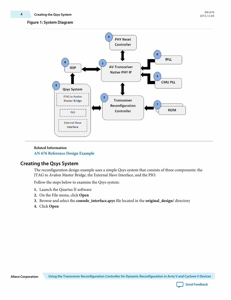
Figure 1: System Diagram
Related InformationAN 676 Reference Design Example
Creating the Qsys SystemThe reconfiguration design example uses a simple Qsys system that consists of three components: theJTAG to Avalon Master Bridge, the External Slave Interface, and the PIO.
Follow the steps below to examine the Qsys system:
1. Launch the Quartus II software2. On the File menu, click Open3. Browse and select the console_interface.qsys file located in the original_design/ directory4. Click Open
4 Creating the Qsys SystemAN-676
2015.12.04
Altera Corporation Using the Transceiver Reconfiguration Controller for Dynamic Reconfiguration in Arria V and Cyclone V Devices
Send Feedback
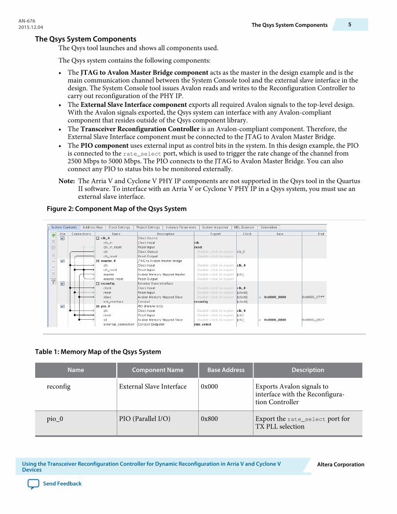
The Qsys System ComponentsThe Qsys tool launches and shows all components used.
The Qsys system contains the following components:
• The JTAG to Avalon Master Bridge component acts as the master in the design example and is themain communication channel between the System Console tool and the external slave interface in thedesign. The System Console tool issues Avalon reads and writes to the Reconfiguration Controller tocarry out reconfiguration of the PHY IP.
• The External Slave Interface component exports all required Avalon signals to the top-level design.With the Avalon signals exported, the Qsys system can interface with any Avalon-compliantcomponent that resides outside of the Qsys component library.
• The Transceiver Reconfiguration Controller is an Avalon-compliant component. Therefore, theExternal Slave Interface component must be connected to the JTAG to Avalon Master Bridge.
• The PIO component uses external input as control bits in the system. In this design example, the PIOis connected to the rate_select port, which is used to trigger the rate change of the channel from2500 Mbps to 5000 Mbps. The PIO connects to the JTAG to Avalon Master Bridge. You can alsoconnect any PIO to status bits to be monitored externally.
Note: The Arria V and Cyclone V PHY IP components are not supported in the Qsys tool in the QuartusII software. To interface with an Arria V or Cyclone V PHY IP in a Qsys system, you must use anexternal slave interface.
Figure 2: Component Map of the Qsys System
Table 1: Memory Map of the Qsys System
Name Component Name Base Address Description
reconfig External Slave Interface 0x000 Exports Avalon signals tointerface with the Reconfigura‐tion Controller
pio_0 PIO (Parallel I/O) 0x800 Export the rate_select port forTX PLL selection
AN-6762015.12.04 The Qsys System Components 5
Using the Transceiver Reconfiguration Controller for Dynamic Reconfiguration in Arria V and Cyclone VDevices
Altera Corporation
Send Feedback
Related InformationQsys System Integration Tool Support
Creating the Transceiver Native PHY IPThe design example uses the Arria V Native PHY IP as a single duplex transceiver channel. Unlike otherPHY IP, the Native PHY IP does not include the Avalon-MM interface. Instead, it exposes all signalsdirectly as ports. In this design example, the Native PHY IP interfaces with the Reset Controller,Reconfiguration Controller, and the ISSP.
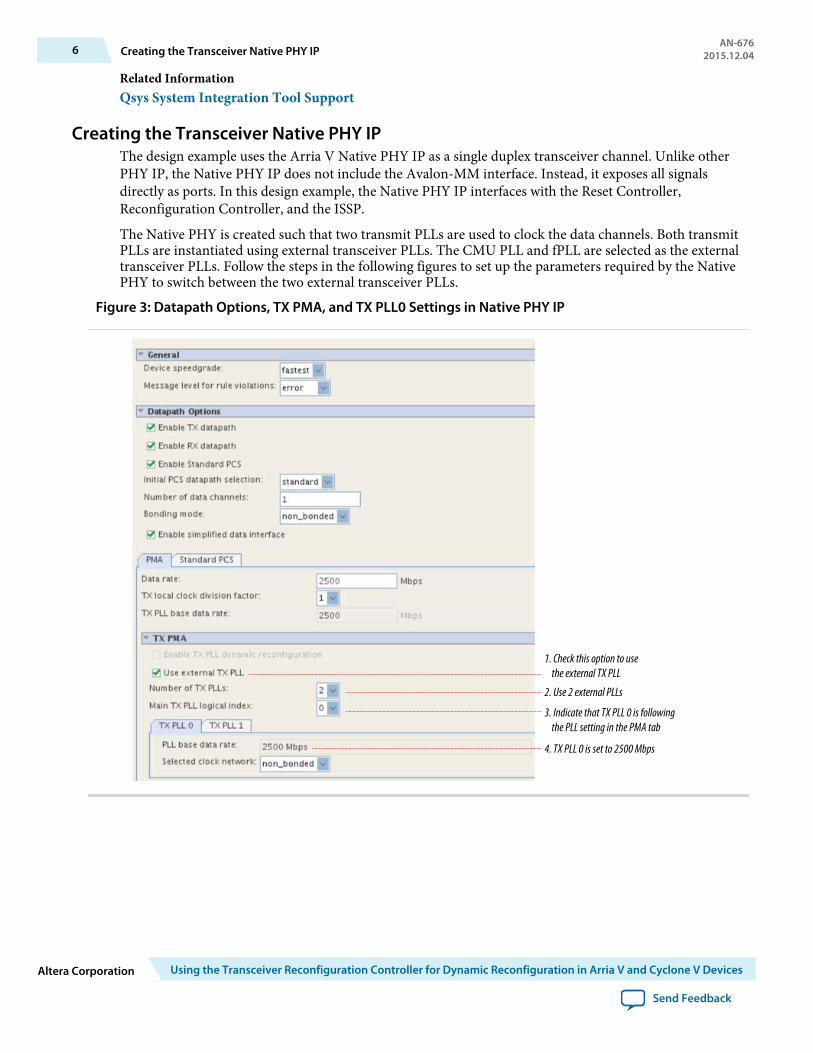
The Native PHY is created such that two transmit PLLs are used to clock the data channels. Both transmitPLLs are instantiated using external transceiver PLLs. The CMU PLL and fPLL are selected as the externaltransceiver PLLs. Follow the steps in the following figures to set up the parameters required by the NativePHY to switch between the two external transceiver PLLs.
Figure 3: Datapath Options, TX PMA, and TX PLL0 Settings in Native PHY IP
1. Check this option to use the external TX PLL
2. Use 2 external PLLs
3. Indicate that TX PLL 0 is following the PLL setting in the PMA tab
4. TX PLL 0 is set to 2500 Mbps
6 Creating the Transceiver Native PHY IPAN-676
2015.12.04
Altera Corporation Using the Transceiver Reconfiguration Controller for Dynamic Reconfiguration in Arria V and Cyclone V Devices
Send Feedback
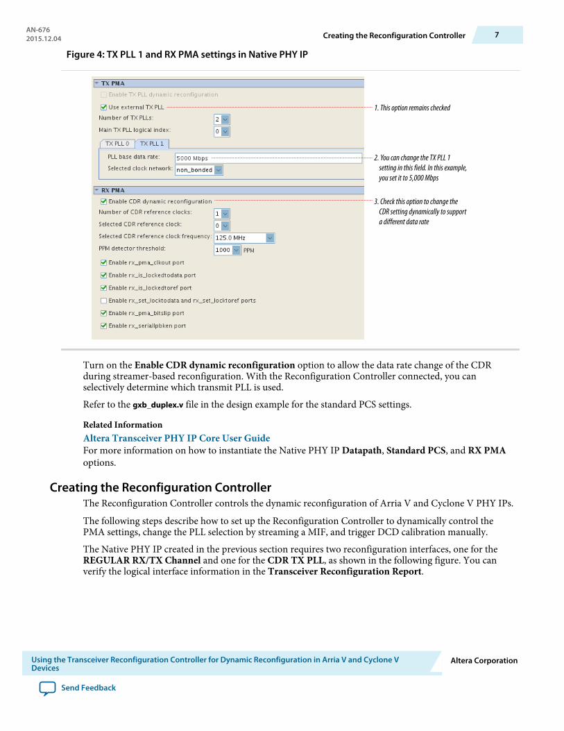
Figure 4: TX PLL 1 and RX PMA settings in Native PHY IP
1. This option remains checked
2. You can change the TX PLL 1 setting in this field. In this example, you set it to 5,000 Mbps
3. Check this option to change the CDR setting dynamically to support a different data rate
Turn on the Enable CDR dynamic reconfiguration option to allow the data rate change of the CDRduring streamer-based reconfiguration. With the Reconfiguration Controller connected, you canselectively determine which transmit PLL is used.
Refer to the gxb_duplex.v file in the design example for the standard PCS settings.
Related InformationAltera Transceiver PHY IP Core User GuideFor more information on how to instantiate the Native PHY IP Datapath, Standard PCS, and RX PMAoptions.
Creating the Reconfiguration ControllerThe Reconfiguration Controller controls the dynamic reconfiguration of Arria V and Cyclone V PHY IPs.
The following steps describe how to set up the Reconfiguration Controller to dynamically control thePMA settings, change the PLL selection by streaming a MIF, and trigger DCD calibration manually.
The Native PHY IP created in the previous section requires two reconfiguration interfaces, one for theREGULAR RX/TX Channel and one for the CDR TX PLL, as shown in the following figure. You canverify the logical interface information in the Transceiver Reconfiguration Report.
AN-6762015.12.04 Creating the Reconfiguration Controller 7
Using the Transceiver Reconfiguration Controller for Dynamic Reconfiguration in Arria V and Cyclone VDevices
Altera Corporation
Send Feedback
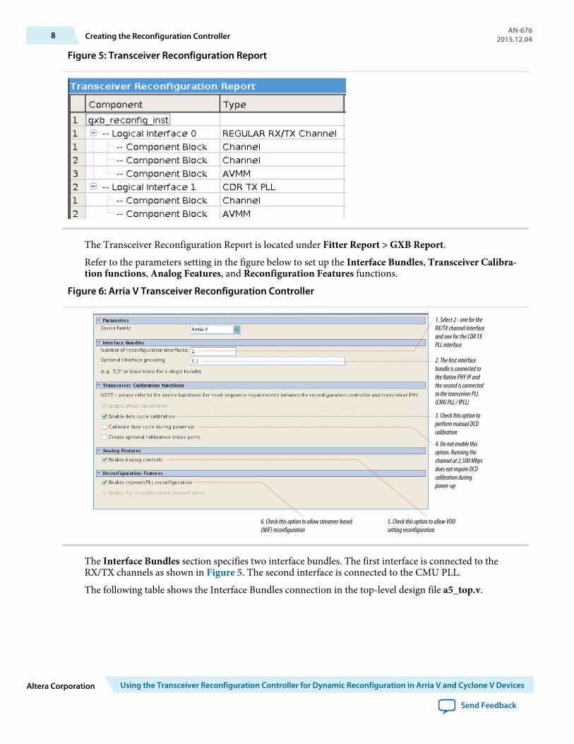
Figure 5: Transceiver Reconfiguration Report
The Transceiver Reconfiguration Report is located under Fitter Report > GXB Report.
Refer to the parameters setting in the figure below to set up the Interface Bundles, Transceiver Calibra‐tion functions, Analog Features, and Reconfiguration Features functions.
Figure 6: Arria V Transceiver Reconfiguration Controller
1. Select 2 - one for the RX/TX channel interface and one for the CDR TX PLL interface
2. The first interface bundle is connected to the Native PHY IP and the second is connected to the transceiver PLL (CMU PLL / fPLL)
3. Check this option to perform manual DCD calibration
4. Do not enable this option. Running the channel at 2,500 Mbps does not require DCD calibration during power-up
5. Check this option to allow VOD setting reconfiguration
6. Check this option to allow streamer-based (MIF) reconfiguration
The Interface Bundles section specifies two interface bundles. The first interface is connected to theRX/TX channels as shown in Figure 5. The second interface is connected to the CMU PLL.
The following table shows the Interface Bundles connection in the top-level design file a5_top.v.
8 Creating the Reconfiguration ControllerAN-676
2015.12.04
Altera Corporation Using the Transceiver Reconfiguration Controller for Dynamic Reconfiguration in Arria V and Cyclone V Devices
Send Feedback
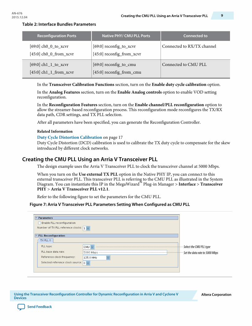
Table 2: Interface Bundles Parameters
Reconfiguration Ports Native PHY/ CMU PLL Ports Connected to
[69:0] ch0_0_to_xcvr
[45:0] ch0_0_from_xcvr
[69:0] reconfig_to_xcvr
[45:0] reconfig_from_xcvr
Connected to RX/TX channel
[69:0] ch1_1_to_xcvr
[45:0] ch1_1_from_xcvr
[69:0] reconfig_to_cmu
[45:0] reconfig_from_cmu
Connected to CMU PLL
In the Transceiver Calibration Functions section, turn on the Enable duty cycle calibration option.
In the Analog Features section, turn on the Enable Analog controls option to enable VOD settingreconfiguration.
In the Reconfiguration Features section, turn on the Enable channel/PLL reconfiguration option toallow the streamer-based reconfiguration process. This reconfiguration mode reconfigures the TX/RXdata path, CDR settings, and TX PLL selection.
After all parameters have been specified, you can generate the Reconfiguration Controller.
Related InformationDuty Cycle Distortion Calibration on page 17Duty Cycle Distortion (DCD) calibration is used to calibrate the TX duty cycle to compensate for the skewintroduced by different clock networks.
Creating the CMU PLL Using an Arria V Transceiver PLLThe design example uses the Arria V Transceiver PLL to clock the transceiver channel at 5000 Mbps.
When you turn on the Use external TX PLL option in the Native PHY IP, you can connect to thisexternal transceiver PLL. This transceiver PLL is referring to the CMU PLL as illustrated in the SystemDiagram. You can instantiate this IP in the MegaWizard™ Plug-in Manager > Interface > TransceiverPHY > Arria V Transceiver PLL v12.1.
Refer to the following figure to set the parameters for the CMU PLL.
Figure 7: Arria V Transceiver PLL Parameters Setting When Configured as CMU PLL
Select the CMU PLL type
Set the data rate to 5000 Mbps
AN-6762015.12.04 Creating the CMU PLL Using an Arria V Transceiver PLL 9
Using the Transceiver Reconfiguration Controller for Dynamic Reconfiguration in Arria V and Cyclone VDevices
Altera Corporation
Send Feedback
You do not have to turn on the Enable PLL reconfiguration option if you are not dynamically reconfi‐guring the PLL parameter settings. This option allows you to change the PLL settings to support differentdata rates.
Note: If you are using an fPLL in your design, if you want to switch the fPLL with another CMU PLL, youmust instantiate the CMU PLL using the Arria V Transceiver PLL IP. Turn on the option Useexternal TX PLL in the Native PHY IP to instantiate a CMU PLL.
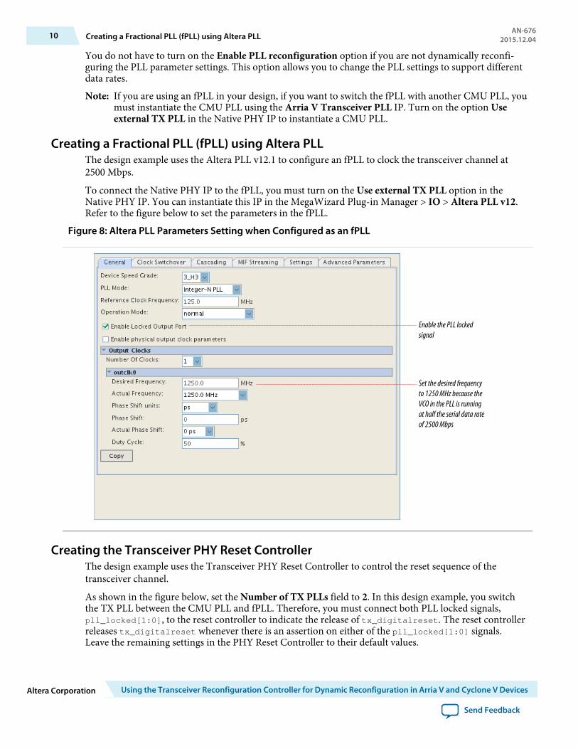
Creating a Fractional PLL (fPLL) using Altera PLLThe design example uses the Altera PLL v12.1 to configure an fPLL to clock the transceiver channel at2500 Mbps.
To connect the Native PHY IP to the fPLL, you must turn on the Use external TX PLL option in theNative PHY IP. You can instantiate this IP in the MegaWizard Plug-in Manager > IO > Altera PLL v12.Refer to the figure below to set the parameters in the fPLL.
Figure 8: Altera PLL Parameters Setting when Configured as an fPLL
Enable the PLL locked signal
Set the desired frequency to 1250 MHz because the VCO in the PLL is running at half the serial data rate of 2500 Mbps
Creating the Transceiver PHY Reset ControllerThe design example uses the Transceiver PHY Reset Controller to control the reset sequence of thetransceiver channel.
As shown in the figure below, set the Number of TX PLLs field to 2. In this design example, you switchthe TX PLL between the CMU PLL and fPLL. Therefore, you must connect both PLL locked signals,pll_locked[1:0], to the reset controller to indicate the release of tx_digitalreset. The reset controllerreleases tx_digitalreset whenever there is an assertion on either of the pll_locked[1:0] signals.Leave the remaining settings in the PHY Reset Controller to their default values.
10 Creating a Fractional PLL (fPLL) using Altera PLLAN-676
2015.12.04
Altera Corporation Using the Transceiver Reconfiguration Controller for Dynamic Reconfiguration in Arria V and Cyclone V Devices
Send Feedback
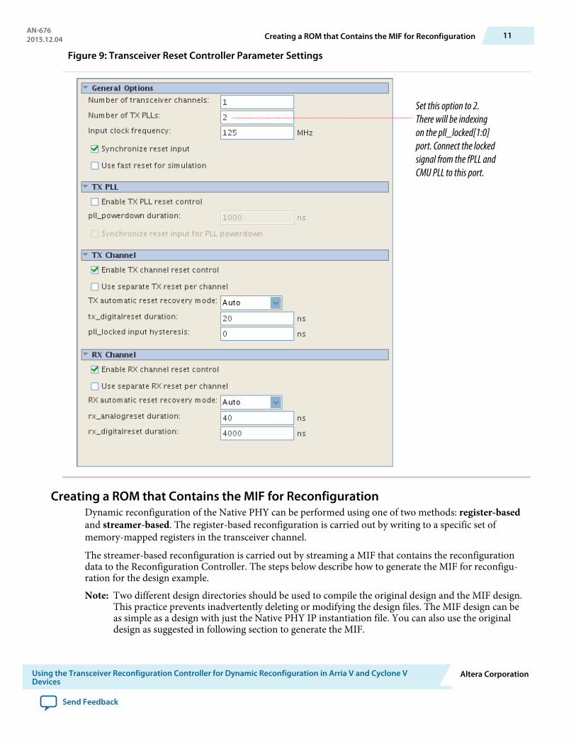
Figure 9: Transceiver Reset Controller Parameter Settings
Set this option to 2. There will be indexing on the pll_locked[1:0] port. Connect the locked signal from the fPLL and CMU PLL to this port.
Creating a ROM that Contains the MIF for ReconfigurationDynamic reconfiguration of the Native PHY can be performed using one of two methods: register-basedand streamer-based. The register-based reconfiguration is carried out by writing to a specific set ofmemory-mapped registers in the transceiver channel.
The streamer-based reconfiguration is carried out by streaming a MIF that contains the reconfigurationdata to the Reconfiguration Controller. The steps below describe how to generate the MIF for reconfigu‐ration for the design example.
Note: Two different design directories should be used to compile the original design and the MIF design.This practice prevents inadvertently deleting or modifying the design files. The MIF design can beas simple as a design with just the Native PHY IP instantiation file. You can also use the originaldesign as suggested in following section to generate the MIF.
AN-6762015.12.04 Creating a ROM that Contains the MIF for Reconfiguration 11
Using the Transceiver Reconfiguration Controller for Dynamic Reconfiguration in Arria V and Cyclone VDevices
Altera Corporation
Send Feedback
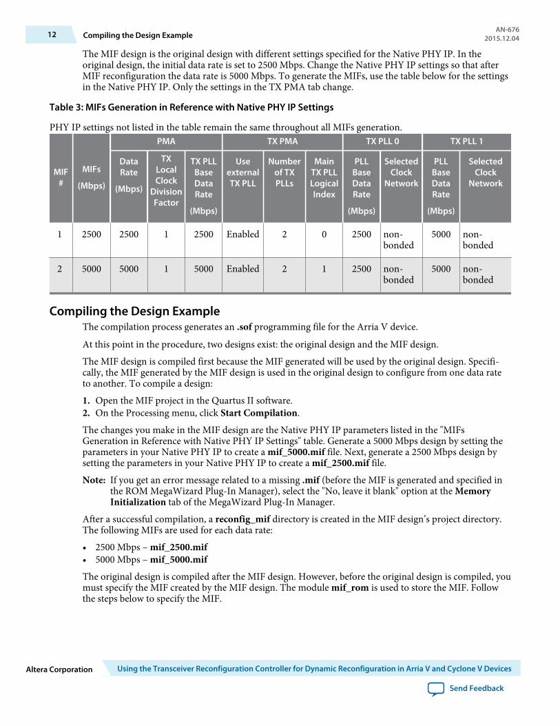
The MIF design is the original design with different settings specified for the Native PHY IP. In theoriginal design, the initial data rate is set to 2500 Mbps. Change the Native PHY IP settings so that afterMIF reconfiguration the data rate is 5000 Mbps. To generate the MIFs, use the table below for the settingsin the Native PHY IP. Only the settings in the TX PMA tab change.
Table 3: MIFs Generation in Reference with Native PHY IP Settings
PHY IP settings not listed in the table remain the same throughout all MIFs generation.
MIF#
MIFs
(Mbps)
PMA TX PMA TX PLL 0 TX PLL 1
DataRate
(Mbps)
TXLocalClock
DivisionFactor
TX PLLBaseDataRate
(Mbps)
UseexternalTX PLL
Numberof TXPLLs
MainTX PLLLogicalIndex
PLLBaseDataRate
(Mbps)
SelectedClock
Network
PLLBaseDataRate
(Mbps)
SelectedClock
Network
1 2500 2500 1 2500 Enabled 2 0 2500 non-bonded
5000 non-bonded
2 5000 5000 1 5000 Enabled 2 1 2500 non-bonded
5000 non-bonded
Compiling the Design ExampleThe compilation process generates an .sof programming file for the Arria V device.
At this point in the procedure, two designs exist: the original design and the MIF design.
The MIF design is compiled first because the MIF generated will be used by the original design. Specifi‐cally, the MIF generated by the MIF design is used in the original design to configure from one data rateto another. To compile a design:
1. Open the MIF project in the Quartus II software.2. On the Processing menu, click Start Compilation.
The changes you make in the MIF design are the Native PHY IP parameters listed in the "MIFsGeneration in Reference with Native PHY IP Settings" table. Generate a 5000 Mbps design by setting theparameters in your Native PHY IP to create a mif_5000.mif file. Next, generate a 2500 Mbps design bysetting the parameters in your Native PHY IP to create a mif_2500.mif file.
Note: If you get an error message related to a missing .mif (before the MIF is generated and specified inthe ROM MegaWizard Plug-In Manager), select the "No, leave it blank" option at the MemoryInitialization tab of the MegaWizard Plug-In Manager.
After a successful compilation, a reconfig_mif directory is created in the MIF design’s project directory.The following MIFs are used for each data rate:
• 2500 Mbps – mif_2500.mif• 5000 Mbps – mif_5000.mifThe original design is compiled after the MIF design. However, before the original design is compiled, youmust specify the MIF created by the MIF design. The module mif_rom is used to store the MIF. Followthe steps below to specify the MIF.
12 Compiling the Design ExampleAN-676
2015.12.04
Altera Corporation Using the Transceiver Reconfiguration Controller for Dynamic Reconfiguration in Arria V and Cyclone V Devices
Send Feedback
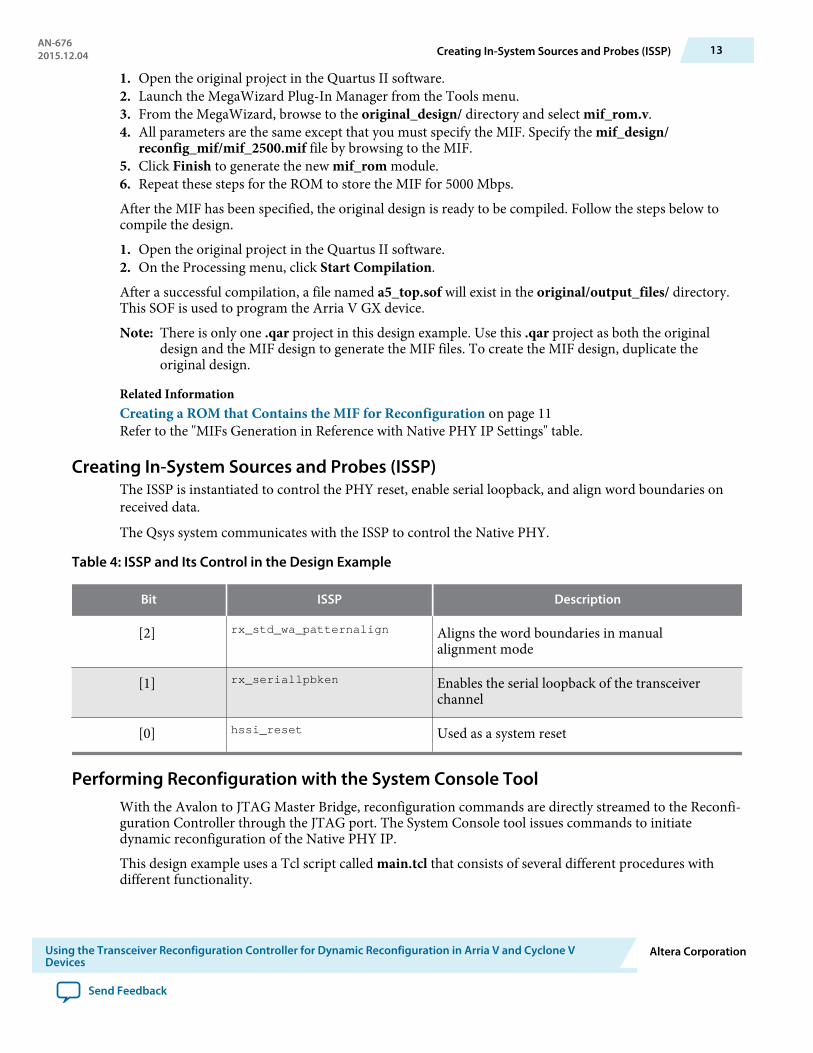
1. Open the original project in the Quartus II software.2. Launch the MegaWizard Plug-In Manager from the Tools menu.3. From the MegaWizard, browse to the original_design/ directory and select mif_rom.v.4. All parameters are the same except that you must specify the MIF. Specify the mif_design/
reconfig_mif/mif_2500.mif file by browsing to the MIF.5. Click Finish to generate the new mif_rom module.6. Repeat these steps for the ROM to store the MIF for 5000 Mbps.
After the MIF has been specified, the original design is ready to be compiled. Follow the steps below tocompile the design.
1. Open the original project in the Quartus II software.2. On the Processing menu, click Start Compilation.
After a successful compilation, a file named a5_top.sof will exist in the original/output_files/ directory.This SOF is used to program the Arria V GX device.
Note: There is only one .qar project in this design example. Use this .qar project as both the originaldesign and the MIF design to generate the MIF files. To create the MIF design, duplicate theoriginal design.
Related InformationCreating a ROM that Contains the MIF for Reconfiguration on page 11Refer to the "MIFs Generation in Reference with Native PHY IP Settings" table.
Creating In-System Sources and Probes (ISSP)The ISSP is instantiated to control the PHY reset, enable serial loopback, and align word boundaries onreceived data.
The Qsys system communicates with the ISSP to control the Native PHY.
Table 4: ISSP and Its Control in the Design Example
Bit ISSP Description
[2] rx_std_wa_patternalign Aligns the word boundaries in manualalignment mode
[1] rx_seriallpbken Enables the serial loopback of the transceiverchannel
[0] hssi_reset Used as a system reset
Performing Reconfiguration with the System Console ToolWith the Avalon to JTAG Master Bridge, reconfiguration commands are directly streamed to the Reconfi‐guration Controller through the JTAG port. The System Console tool issues commands to initiatedynamic reconfiguration of the Native PHY IP.
This design example uses a Tcl script called main.tcl that consists of several different procedures withdifferent functionality.
AN-6762015.12.04 Creating In-System Sources and Probes (ISSP) 13
Using the Transceiver Reconfiguration Controller for Dynamic Reconfiguration in Arria V and Cyclone VDevices
Altera Corporation
Send Feedback

Note: Program the Arria V GX device with the SOF generated in the previous section before launchingthe System Console. Having both the programmer and System Console open simultaneously cancause programming errors.
Before any reconfiguration can take place, you must first launch the System Console tool. To launch theSystem Console, perform the following steps:
1. Program the Arria V Device with the SOF generated from the original design2. Launch the Quartus II software3. From the Quartus II software, on the Tools menu, click Qsys4. From the Qsys tool, on the Tools menu, click System Console5. Ensure that the present working directory contains main.tclThe following table lists the procedures in main.tcl. You can type in a procedure name and its value toexecute the reconfiguration process. Verify your results with the signal tap file (stp1.stp) by looking at thesignals listed in the following table.
Table 5: Description of Procedures in main.tcl
Command Name <Value> Description
txpll_register <Value>
0 Select logical TX PLL 0 as TX PLL (fPLL). Only thetx_std_clkout frequency is updated.
1 Select logical TX PLL 1 as TX PLL (CMU PLL).Only the tx_std_clkout frequency is updated.
txpll_mif <Value>
2500 Select logical TX PLL 0 as TX PLL (fPLL). Both thetx_std_clkout and rx_std_clkout frequenciesare updated.
5000 Select logical TX PLL 1 as TX PLL (CMU PLL).Both the tx_std_clkout and rx_std_clkoutfrequencies are updated.
reset N/A System Reset
sloopback <Value>
1 Enable serial loopback. Verify with therx_seriallpbken port in the signal tap file
0 Disable serial loopback. Verify with therx_seriallpbken port in the signal tap file
read_vod N/A Read back VOD value (read back data in hexadec‐imal value)
write_vod <Value> 0-63 Writing VOD value with valid settings of 0-63
14 Performing Reconfiguration with the System Console ToolAN-676
2015.12.04
Altera Corporation Using the Transceiver Reconfiguration Controller for Dynamic Reconfiguration in Arria V and Cyclone V Devices
Send Feedback
Command Name <Value> Description
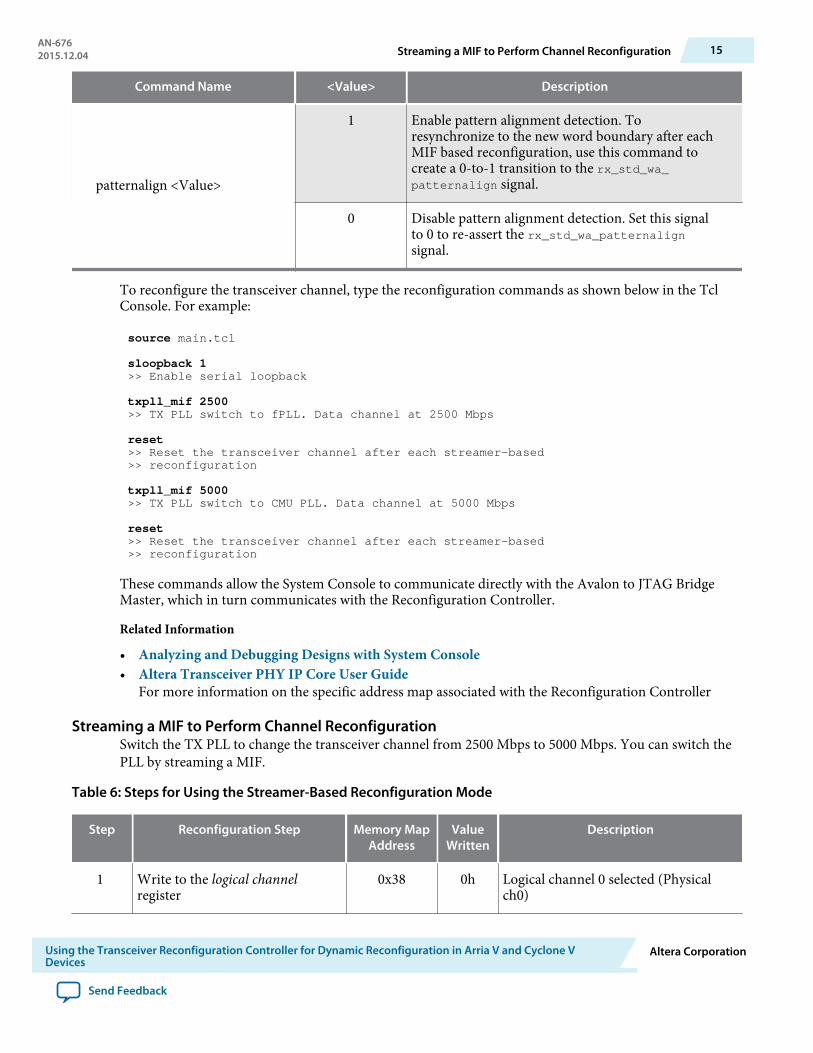
patternalign <Value>
1 Enable pattern alignment detection. Toresynchronize to the new word boundary after eachMIF based reconfiguration, use this command tocreate a 0-to-1 transition to the rx_std_wa_patternalign signal.
0 Disable pattern alignment detection. Set this signalto 0 to re-assert the rx_std_wa_patternalignsignal.
To reconfigure the transceiver channel, type the reconfiguration commands as shown below in the TclConsole. For example:
source main.tcl
sloopback 1>> Enable serial loopback
txpll_mif 2500>> TX PLL switch to fPLL. Data channel at 2500 Mbps
reset>> Reset the transceiver channel after each streamer-based >> reconfiguration txpll_mif 5000>> TX PLL switch to CMU PLL. Data channel at 5000 Mbps
reset>> Reset the transceiver channel after each streamer-based >> reconfiguration
These commands allow the System Console to communicate directly with the Avalon to JTAG BridgeMaster, which in turn communicates with the Reconfiguration Controller.
Related Information
• Analyzing and Debugging Designs with System Console• Altera Transceiver PHY IP Core User Guide
For more information on the specific address map associated with the Reconfiguration Controller
Streaming a MIF to Perform Channel ReconfigurationSwitch the TX PLL to change the transceiver channel from 2500 Mbps to 5000 Mbps. You can switch thePLL by streaming a MIF.
Table 6: Steps for Using the Streamer-Based Reconfiguration Mode
Step Reconfiguration Step Memory MapAddress
ValueWritten
Description
1 Write to the logical channelregister
0x38 0h Logical channel 0 selected (Physicalch0)
AN-6762015.12.04 Streaming a MIF to Perform Channel Reconfiguration 15
Using the Transceiver Reconfiguration Controller for Dynamic Reconfiguration in Arria V and Cyclone VDevices
Altera Corporation
Send Feedback
Step Reconfiguration Step Memory MapAddress
ValueWritten
Description
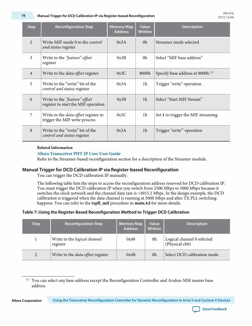
2 Write MIF mode 0 to the controland status register
0x3A 0h Streamer mode selected
3 Write to the "feature” offsetregister
0x3B 0h Select “MIF base address”
4 Write to the data offset register 0x3C 8000h Specify base address at 8000h (1)
5 Write to the “write” bit of thecontrol and status register
0x3A 1h Trigger "write" operation
6 Write to the "feature” offsetregister to start the MIF operation
0x3B 1h Select “Start MIF Stream”
7 Write to the data offset register totrigger the MIF write process
0x3C 1h Set 1 to trigger the MIF streaming
8 Write to the “write” bit of thecontrol and status register
0x3A 1h Trigger "write"’ operation
Related InformationAltera Transceiver PHY IP Core User GuideRefer to the Streamer-based reconfiguration section for a description of the Streamer module.
Manual Trigger for DCD Calibration IP via Register-based ReconfigurationYou can trigger the DCD calibration IP manually.
The following table lists the steps to access the reconfiguration address reserved for DCD calibration IP.You must trigger the DCD calibration IP when you switch from 2500 Mbps to 5000 Mbps because itswitches the clock network and the channel data rate is >4915.2 Mbps. In the design example, the DCDcalibration is triggered when the data channel is running at 5000 Mbps and after TX PLL switchinghappens. You can refer to the txpll_mif procedure in main.tcl for more details.
Table 7: Using the Register-Based Reconfiguration Method to Trigger DCD Calibration
Step Reconfiguration Step Memory MapAddress
ValueWritten
Description
1 Write to the logical channelregister
0x48 0h Logical channel 0 selected(Physical ch0)
2 Write to the data offset register 0x4B 0h Select DCD calibration mode
(1) You can select any base address except the Reconfiguration Controller and Avalon-MM master baseaddress
16 Manual Trigger for DCD Calibration IP via Register-based ReconfigurationAN-676
2015.12.04
Altera Corporation Using the Transceiver Reconfiguration Controller for Dynamic Reconfiguration in Arria V and Cyclone V Devices
Send Feedback
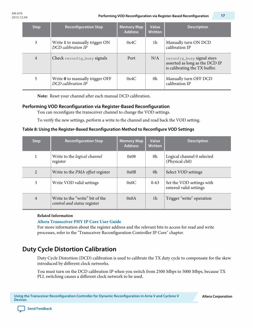
Step Reconfiguration Step Memory MapAddress
ValueWritten
Description
3 Write 1 to manually trigger ONDCD calibration IP
0x4C 1h Manually turn ON DCDcalibration IP
4 Check reconfig_busy signals Port N/A reconfig_busy signal staysasserted as long as the DCD IPis calibrating the TX buffer.
5 Write 0 to manually trigger OFFDCD calibration IP
0x4C 0h Manually turn OFF DCDcalibration IP
Note: Reset your channel after each manual DCD calibration.
Performing VOD Reconfiguration via Register-Based ReconfigurationYou can reconfigure the transceiver channel to change the VOD settings.
To verify the new settings, perform a write to the channel and read back the VOD setting.
Table 8: Using the Register-Based Reconfiguration Method to Reconfigure VOD Settings
Step Reconfiguration Step Memory MapAddress
ValueWritten
Description
1 Write to the logical channelregister
0x08 0h Logical channel 0 selected(Physical ch0)
2 Write to the PMA offset register 0x0B 0h Select VOD settings
3 Write VOD valid settings 0x0C 0-63 Set the VOD settings withentered valid settings
4 Write to the “write” bit of thecontrol and status register
0x0A 1h Trigger "write" operation
Related InformationAltera Transceiver PHY IP Core User GuideFor more information about the register address and the relevant bits to access for read and writeprocesses, refer to the "Transceiver Reconfiguration Controller IP Core" chapter.
Duty Cycle Distortion CalibrationDuty Cycle Distortion (DCD) calibration is used to calibrate the TX duty cycle to compensate for the skewintroduced by different clock networks.
You must turn on the DCD calibration IP when you switch from 2500 Mbps to 5000 Mbps, because TXPLL switching causes a different clock network to be used.
AN-6762015.12.04 Performing VOD Reconfiguration via Register-Based Reconfiguration 17
Using the Transceiver Reconfiguration Controller for Dynamic Reconfiguration in Arria V and Cyclone VDevices
Altera Corporation
Send Feedback
Enable the DCD calibration IP for Arria V and Cyclone V devices if either of the following conditions isapplicable:
• Data rate is ≥ 4915.2 Mbps• Clock network switching (TX PLL switching) and the data rate is ≥ 4915.2 Mbps
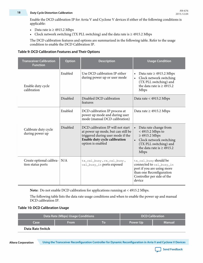
The DCD calibration features and options are summarized in the following table. Refer to the usagecondition to enable the DCD Calibration IP.
Table 9: DCD Calibration Features and Their Options
Transceiver CalibrationFunction
Option Description Usage Condition
Enable duty cyclecalibration
Enabled Use DCD calibration IP eitherduring power up or user mode
• Data rate ≥ 4915.2 Mbps• Clock network switching
(TX PLL switching) andthe data rate is ≥ 4915.2Mbps
Disabled Disabled DCD calibrationfeatures
Data rate < 4915.2 Mbps
Calibrate duty cycleduring power up
Enabled DCD calibration IP process atpower up mode and during usermode (manual DCD calibration)
Data rate ≥ 4915.2 Mbps
Disabled DCD calibration IP will not startat power up mode, but can still betriggered during user mode if theEnable duty cycle calibrationoption is enabled
• Data rate change from< 4915.2 Mbps to≥ 4915.2 Mbps
• Clock network switching(TX PLL switching) andthe data rate is ≥ 4915.2Mbps
Create optional calibra‐tion status ports
N/A tx_cal_busy , rx_cal_busy ,cal_busy_in ports exposed
tx_cal_busy should beconnected to cal_busy_inport if you are using morethan one ReconfigurationController per side of thedevice
Note: Do not enable DCD calibration for applications running at < 4915.2 Mbps.
The following table lists the data rate usage conditions and when to enable the power up and manualDCD calibration IP.
Table 10: DCD Calibration Usage
Data Rate (Mbps) Usage Conditions DCD Calibration
Case From To Power Up Manual
Data Rate Switch
18 Duty Cycle Distortion CalibrationAN-676
2015.12.04
Altera Corporation Using the Transceiver Reconfiguration Controller for Dynamic Reconfiguration in Arria V and Cyclone V Devices
Send Feedback
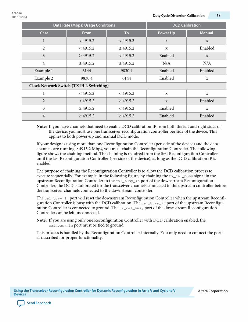
Data Rate (Mbps) Usage Conditions DCD Calibration
Case From To Power Up Manual
1 < 4915.2 < 4915.2 x x2 < 4915.2 ≥ 4915.2 x Enabled3 ≥ 4915.2 < 4915.2 Enabled x4 ≥ 4915.2 ≥ 4915.2 N/A N/A
Example 1 6144 9830.4 Enabled EnabledExample 2 9830.4 6144 Enabled x
Clock Network Switch (TX PLL Switching)1 < 4915.2 < 4915.2 x x2 < 4915.2 ≥ 4915.2 x Enabled3 ≥ 4915.2 < 4915.2 Enabled x4 ≥ 4915.2 ≥ 4915.2 Enabled Enabled
Note: If you have channels that need to enable DCD calibration IP from both the left and right sides ofthe device, you must use one transceiver reconfiguration controller per side of the device. Thisapplies to both power-up and manual DCD mode.
If your design is using more than one Reconfiguration Controller (per side of the device) and the datachannels are running ≥ 4915.2 Mbps, you must chain the Reconfiguration Controller. The followingfigure shows the chaining method. The chaining is required from the first Reconfiguration Controlleruntil the last Reconfiguration Controller (per side of the device), as long as the DCD calibration IP isenabled.
The purpose of chaining the Reconfiguration Controller is to allow the DCD calibration process toexecute sequentially. For example, in the following figure, by chaining the tx_cal_busy signal in theupstream Reconfiguration Controller to the cal_busy_in port of the downstream ReconfigurationController, the DCD is calibrated for the transceiver channels connected to the upstream controller beforethe transceiver channels connected to the downstream controller.
The cal_busy_in port will reset the downstream Reconfiguration Controller when the upstream Reconfi‐guration Controller is busy with the DCD calibration. The cal_busy_in port of the upstream Reconfigu‐ration Controller is connected to ground. The tx_cal_busy port of the downstream ReconfigurationController can be left unconnected.
Note: If you are using only one Reconfiguration Controller with DCD calibration enabled, thecal_busy_in port must be tied to ground.
This process is handled by the Reconfiguration Controller internally. You only need to connect the portsas described for proper functionality.
AN-6762015.12.04 Duty Cycle Distortion Calibration 19
Using the Transceiver Reconfiguration Controller for Dynamic Reconfiguration in Arria V and Cyclone VDevices
Altera Corporation
Send Feedback
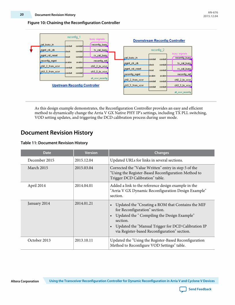
Figure 10: Chaining the Reconfiguration Controller
As this design example demonstrates, the Reconfiguration Controller provides an easy and efficientmethod to dynamically change the Arria V GX Native PHY IP's settings, including TX PLL switching,VOD setting updates, and triggering the DCD calibration process during user mode.
Document Revision History
Table 11: Document Revision History
Date Version Changes
December 2015 2015.12.04 Updated URLs for links in several sections.
March 2015 2015.03.04 Corrected the "Value Written" entry in step 5 of the"Using the Register-Based Reconfiguration Method toTrigger DCD Calibration" table.
April 2014 2014.04.01 Added a link to the reference design example in the"Arria V GX Dynamic Reconfiguration Design Example"section.
January 2014 2014.01.21 • Updated the "Creating a ROM that Contains the MIFfor Reconfiguration" section.
• Updated the " Compiling the Design Example"section.
• Updated the "Manual Trigger for DCD Calibration IPvia Register-based Reconfiguration" section.
October 2013 2013.10.11 Updated the "Using the Register-Based ReconfigurationMethod to Reconfigure VOD Settings" table.
20 Document Revision HistoryAN-676
2015.12.04
Altera Corporation Using the Transceiver Reconfiguration Controller for Dynamic Reconfiguration in Arria V and Cyclone V Devices
Send Feedback
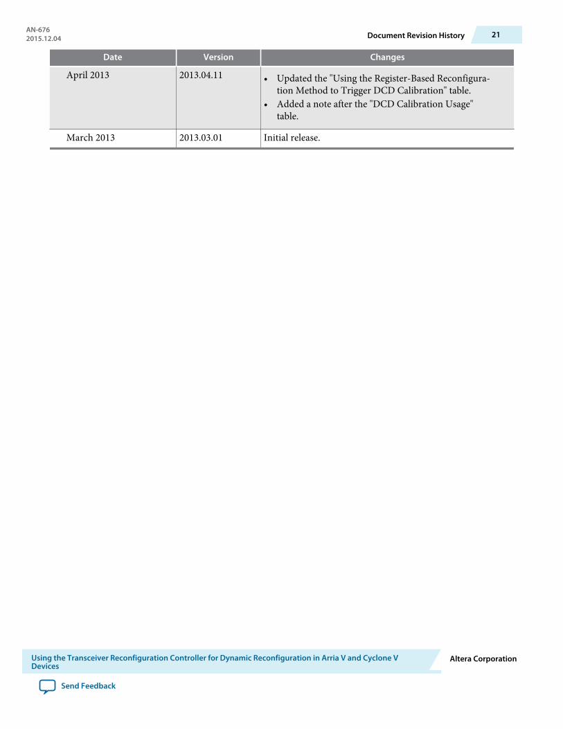
Date Version Changes
April 2013 2013.04.11 • Updated the "Using the Register-Based Reconfigura‐tion Method to Trigger DCD Calibration" table.
• Added a note after the "DCD Calibration Usage"table.
March 2013 2013.03.01 Initial release.
AN-6762015.12.04 Document Revision History 21
Using the Transceiver Reconfiguration Controller for Dynamic Reconfiguration in Arria V and Cyclone VDevices
Altera Corporation
Send Feedback


