

Redefine your comfort zone. ™ | www.titus-hvac.com
energy solutions
vav retrofit terminals
retrofit
P

P2
P
Rede
fine
your
com
fort
zone
™ |
ww
w.ti
tus-
hvac
.com
vav retrofit terminals
VAV
RETR
OFIT
TER
MIN
ALS
QCV Slide-In Series ............................................................................................................................................................................ P13Features and Benefits ................................................................................................................................................................ P13Applications ................................................................................................................................................................................ P14Dimensions ................................................................................................................................................................................. P15Performance Data ....................................................................................................................................................................... P16
Table of Contentsvav retrofit terminals products
notice
external round duct seriesEXX, PECX and ECV External Round Duct Series ................................................................................................................................. P5
Features and Benefits .................................................................................................................................................................. P5Applications .................................................................................................................................................................................. P6Dimensions ................................................................................................................................................................................... P8Performance Data ....................................................................................................................................................................... P10
Application Icons Key ........................................................................................................................................................................... P2VAV Retrofit Terminals Products .......................................................................................................................................................... P3
ECT Special Purpose and Internal Retrofit Series .............................................................................................................................. P18Features and Benefits ................................................................................................................................................................ P18Applications ................................................................................................................................................................................ P19ECT-AN for Anemostat Terminals ............................................................................................................................................... P21ECT-BC for Barber-Colman Terminals ......................................................................................................................................... P22ECT-BU for Buensod Terminals ................................................................................................................................................... P23ECT-CN for Connor Terminals ..................................................................................................................................................... P24ECT-HC for Titus Terminals ......................................................................................................................................................... P25ECT-KR for Krueger Terminals .................................................................................................................................................... P26ECT-TB for Tuttle & Bailey Terminals .......................................................................................................................................... P27ECT-L Series ................................................................................................................................................................................ P28
Notice ................................................................................................................................................................................................. P29
slide-in series
special purpose and internal retrofit series
APPLICATION ICONS KEY
retrofit
energy solutions
contributes toward energy savings by reducing operating costs of air distribution devices
for use in retrofitting older products into modern designs & systems

P
P3
Redefine your comfort zone™
| ww
w.titus-hvac.com
vav retrofit terminals
VAV RETROFIT TERM
INALS
VAV Retrofit Terminal Products
EXX ECX
external round duct series
ECV
pages: P5-P12
pages: P13-P17
QCV
slide-in series
VARIABLE AIR VOLUME• Converts older constant volume systems into modern
energy efficient variable air volume systems
• Low installation costs
• Available in a variety of sizes
• The casing can be configured to mount on either the right or left side of the existing duct
• Variety of velocity control options available
VARIABLE AIR VOLUME• Converts older constant volume
systems into modern energy efficient variable air volume systems
• Flow measurement taps included for easy balancing connections
• Simple & easy installation
VARIABLE AIR VOLUME• Converts older constant volume
systems into modern energy efficient variable air volume systems
• Flow measurement taps included for easy balancing connections
• Simple & easy installation
• Metal cover protects pneumatic velocity controller
VARIABLE AIR VOLUME• Converts older constant volume
systems into modern energy efficient variable air volume systems
• Flow measurement taps included for easy balancing connections
• Simple & easy installation
• Metal cover protects velocity controller
• Variety of control options available
P4
P
Rede
fine
your
com
fort
zone
™ |
ww
w.ti
tus-
hvac
.com
vav retrofit terminals
VAV
RETR
OFIT
TER
MIN
ALS
ECT-AN
ECT-HC
ECT-BC
ECT-KR
ECT-BU
ECT-TB
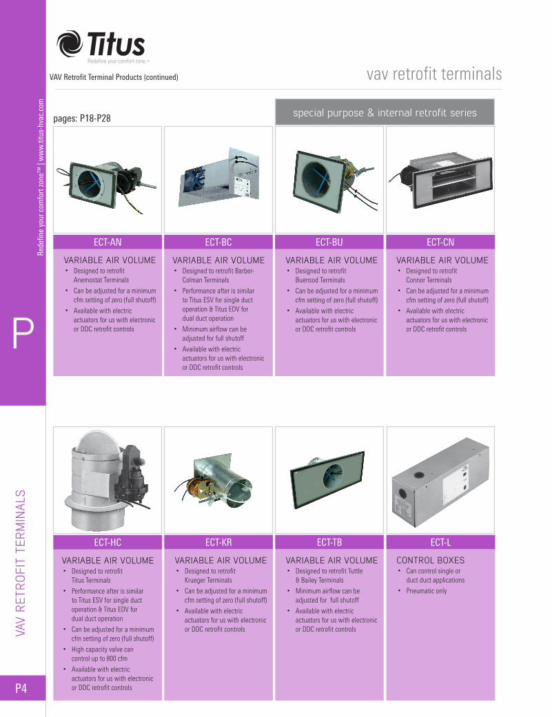
special purpose & internal retrofit series
ECT-CN
ECT-L
VARIABLE AIR VOLUME• Designed to retrofit
Anemostat Terminals
• Can be adjusted for a minimum cfm setting of zero (full shutoff)
• Available with electric actuators for us with electronic or DDC retrofit controls
VARIABLE AIR VOLUME• Designed to retrofit
Titus Terminals
• Performance after is similar to Titus ESV for single duct operation & Titus EDV for dual duct operation
• Can be adjusted for a minimum cfm setting of zero (full shutoff)
• High capacity valve can control up to 800 cfm
• Available with electric actuators for us with electronic or DDC retrofit controls
VARIABLE AIR VOLUME• Designed to retrofit
Buensod Terminals
• Can be adjusted for a minimum cfm setting of zero (full shutoff)
• Available with electric actuators for us with electronic or DDC retrofit controls
VARIABLE AIR VOLUME• Designed to retrofit Tuttle
& Bailey Terminals
• Minimum airflow can be adjusted for full shutoff
• Available with electric actuators for us with electronic or DDC retrofit controls
VARIABLE AIR VOLUME• Designed to retrofit Barber-
Colman Terminals
• Performance after is similar to Titus ESV for single duct operation & Titus EDV for dual duct operation
• Minimum airflow can be adjusted for full shutoff
• Available with electric actuators for us with electronic or DDC retrofit controls
VARIABLE AIR VOLUME• Designed to retrofit
Krueger Terminals
• Can be adjusted for a minimum cfm setting of zero (full shutoff)
• Available with electric actuators for us with electronic or DDC retrofit controls
VARIABLE AIR VOLUME• Designed to retrofit
Connor Terminals
• Can be adjusted for a minimum cfm setting of zero (full shutoff)
• Available with electric actuators for us with electronic or DDC retrofit controls
CONTROL BOXES• Can control single or
duct duct applications
• Pneumatic only
pages: P18-P28
VAV Retrofit Terminal Products (continued)

P
P5
Redefine your comfort zone™
| ww
w.titus-hvac.com
vav retrofit terminals
Titus External Round Retrofit Terminals can upgrade those old existing HVAC systems to current standards of energy efficiency and comfort!
External round retrofit terminals are designed to easily convert the old system powered or constant volume systems to more energy efficient variable volume systems. They may also be used in newly designed systems as air measuring devices and exhaust control valves.
With Titus external round retrofit terminals, you never have to worry about a lengthy conversion process. Compact and light weight, these units install quickly in cramped spaces, supported only by the existing ductwork. The simple cylindrical casing matches standard round duct at both inlet and outlet.
ECV Series and PECX units can be inserted in branch ducts where no control units have been before. They may also be used to replace older units or added to the inlets of existing units that are entirely or partly deactivated.
The ECV Series terminals are available from Titus with pneumatic, electric, analog electronic or direct digital controls (DDCs). Flexibility in application makes selecting Titus external round terminals the simple solution for any retrofit project.
Overview - External Round Duct SeriesFEATURES AND BENEFITS
EXTERNAL RO
UN
D D
UCT SERIES
Multiple rolled beads on the casingensure roundness, while providing
the benefit of leak free connectionsto round ducts.
Both ends are sized to allow easyinsertion into standard hard or flexible
round ducts.
AeroCross™ multi-point, centeraveraging sensor amplifies flow signal
and ensures control accuracy,regardless of inlet duct configuration.
Stainless steel casing is available foruse in areas where hazardousenvrionments exist.
Cast position indicator on damper shaftfor easier monitoring of damper position.Shaft is ½-inch diameter for compatibility
with almost any actuator design.
Delrin® damper bearings are unaffected by temperature and humidity, andprevent binding.
Sheet metal cover (not shown) protectspneumatic velocity controller (optional).
Special damper design provides smoothflow and reduced sound levels.
Flow measurement taps includedfor easy balancing connections.
Field convertible linkage (pneumaticcontrols) allows NO/NC changever withoutactuator removal.
DECV
compatibilityuator design.
al Speciandflow an
Both ends are sized to allow easyinsertion into standard hard or flexible round ducts.
AeroCross™ multi-point, centeraveraging sensor amplifies flow signal
and ensures control accuracy,regardless of inlet duct configuration.
Flow measurement taps includedfor easy balancing connections.
EXX
Both ends are sized to allow easyinsertion into standard hard or flexible
round ducts.
AeroCross™ multi-point, centeraveraging sensor amplifies flow signal
and ensures control accuracy,regardless of inlet duct configuration.
Sheet metal cover protects pneumaticvelocity controller (standard).
Flow measurement taps includedfor easy balancing connections.
PECX

P6
P
Rede
fine
your
com
fort
zone
™ |
ww
w.ti
tus-
hvac
.com
vav retrofit terminals
APPL
ICAT
ION
S
APPLICATIONS
EXISTING PNEUMATIC DUAL DUCT UNIT: CONVERTING TO SINGLE DUCT VAV One inlet is capped off. Constant volume regulators are removed. Titus PECX is installed on cooling inlet of existing unit. Existing thermostat and damper actuator now connect to controller on PECX.
Unit now provides pressure independent variable air volume, cooling (or heating) only, regardless of whether existing thermostat is direct acting or reverse acting, or whether damper is normally open or normally closed.
EXISTING PNEUMATIC DUAL DUCT: CONVERTING TO DUAL DUCT VAV; TWO EXISTING DAMPER ACTUATORS (Option 1)Existing constant volume regulators are retained and used. Cooling inlet is left as is. PECX is installed on heating inlet. Existing room thermostat is connected to both existing cooling damper actuator and to the Titus controller on the PECX, which controls existing heating damper actuator.
This conversion provides variable air volume without wasteful simultaneous heating and cooling. Heating control is pressure independent; cooling is pressure dependent. Maximum cooling cfm is limited by existing constant volume regulators. Maximum heating cfm (less than cooling) is limited by adjustment of PECX. A mixing minimum airflow can be obtained with a start point adjustment using the Titus II Controller.
(Option 2)For pressure independent control of both heating and cooling, constant volume regulators are deactivated or removed. PECXs are installed on both heating and cooling inlets.
Existing room thermostat is connected to Titus controllers on both PECXs, which control both existing damper actuators. A mixing minimum airflow can be obtained with a start point adjustment using the Titus II Controller.
Converting Existing Pneumatic Dual Duct to Single Duct VAV
PECX
20-25 psiMain Air
ExistingDamperActuator
OneInletCapped
M T
ConstantVolumeRegulator(s)Deactivatedor RemovedController
Cold Air
Converting Existing Pneumatic Dual Duct to Single Duct VAV (Option 1)
* Max CLG is determined by existing constant volume regulator setting
Converting Existing Pneumatic Dual Duct to Single Duct VAV (Option 2)
* Max CLG is determined by existing constant volume regulator setting
Max.
Min.
Room Temperature Increase
cfm
Incr
ease
20-25 psiMain Air
M ExistingDamperActuator
ConstantVolumeRegulator(s)Retainedand Used
ExistingCold Duct
PECX
Controller
Max CLG*
Max HTG
Room Temperature Increase
cfm
Incr
ease
Controller
Controller20-25psiMainAir
ConstantVolumeRegulator(s)Retainedand Used
ExistingDamperActuator (Both SIdes)
PECXPECX
M
T
Max CLG*
Max HTG
Room Temperature Increase
cfm
Incr
ease
P
P7
Redefine your comfort zone™
| ww
w.titus-hvac.com
vav retrofit terminals
APPLICATION
S
APPLICATIONS
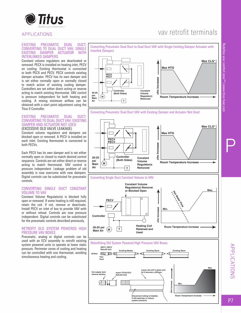
EXISTING PNEUMATIC DUAL DUCT: CONVERTING TO DUAL DUCT VAV; SINGLE EXISTING DAMPER ACTUATOR WITH INTERLINKED DAMPERS Constant volume regulators are deactivated or removed. PECX is installed on heating inlet, PECV on cooling. Existing thermostat is connected to both PECX and PECV. PECX controls existing damper actuator. PECV has its own damper and is set either normally open or normally closed to match action of existing cooling damper. Controllers are set either direct acting or reverse acting to match existing thermostat. VAV control is pressure independent for both heating and cooling. A mixing minimum airflow can be obtained with a start point adjustment using the Titus II Controller.
EXISTING PNEUMATIC DUAL DUCT: CONVERTING TO DUAL DUCT VAV; EXISTING DAMPER AND ACTUATOR NOT USED (EXCESSIVE OLD VALVE LEAKAGE) Constant volume regulators and dampers are blocked open or removed. A PECV is installed on each inlet. Existing thermostat is connected to both PECVs.
Each PECV has its own damper and is set either normally open or closed to match desired control sequence. Controls are set either direct or reverse acting to match thermostat. VAV control is pressure independent. Leakage problem of old assembly is now overcome with new dampers. Digital controls can be substituted for pneumatic controls.
CONVERTING SINGLE DUCT CONSTANT VOLUME TO VAVConstant Volume Regulator(s) is blocked fully open or removed. If some heating is still required, retain the coil. If not, remove or deactivate. Install PECV on inlet of box to provide VAV with or without reheat. Controls are now pressure independent. Digital controls can be substituted for the pneumatic controls described previously.
RETROFIT OLD SYSTEM POWERED HIGH PRESSURE VAV BOXES Pneumatic, analog or digital controls can be used with an ECV assembly to retrofit existing system powered units to operate at lower static pressure. Perimeter zones of cooling and heating can be controlled with one thermostat, avoiding simultaneous heating and cooling.
Converting Pneumatic Dual Duct to Dual Duct VAV with Single Existing Damper Actuator with Interlink Dampers
ConstantVolumeRegulator(s)Removed
Controller(Both Sides)20-25
psiMainAir
PECXPECV
M
T
Converting Pneumatic Dual Duct VAV with Existing Damper and Actuator Not Used
Converting Single Duct Constant Volume to VAV
Max CLG*
Max HTG
Room Temperature Increase
cfm
Incr
ease
ConstantVolumeRegulator(s)Removed
Controller(Both Sides)
20-25psiMainAir
PECVPECV
M
T
Max CLG*
Max HTG
Room Temperature Increase
cfm
Incr
ease
Constant VolumeRegulator(s) Removedor Blocked Open
Controller
20-25 psiMain Air
Heating CoilRetained andUsed
PECV
M T
Max.
Min.
Hot Water Flow
Room Temperature Increase
cfm
Incr
ease
Retrofitting Old System Powered High Pressure VAV BoxesAECV, DECVRetrofit Unit
Airflow
FlexDuct
Existing Master
Cut supply ductremove section.
Insert TITUS ECVRetrofit Unit.
Disconnect tubing to bladder,if still opening, to reduce system pressure.
Leave old unit in place andlet it become a diffuser.
Existing Slave Existing Slave
Max.
Min.
Room Temperature Increase
cfm
Incr
ease
P8
P
Rede
fine
your
com
fort
zone
™ |
ww
w.ti
tus-
hvac
.com
vav retrofit terminals
DIM
ENSI
ONS
DIMENSIONS
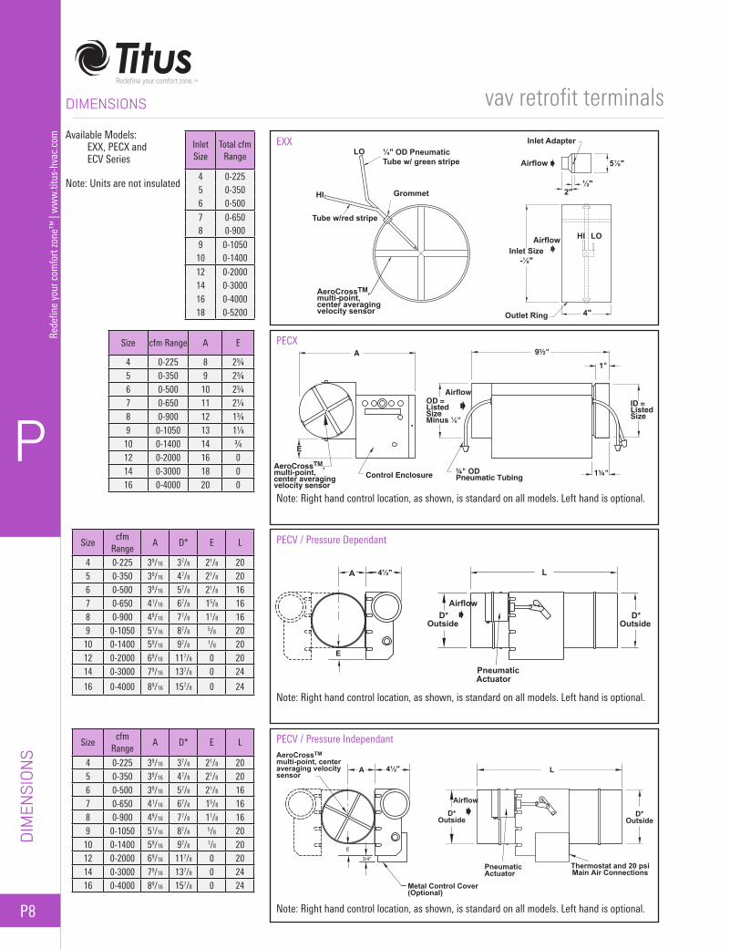
Available Models: EXX, PECX and
ECV Series
Note: Units are not insulated
Inlet Size
Total cfm Range
4 0-2255 0-3506 0-500
7 0-6508 0-900
9 0-105010 0-1400
12 0-200014 0-300016 0-400018 0-5200
Size cfm Range A E
4 0-225 8 2¾5 0-350 9 2¾6 0-500 10 2¾7 0-650 11 2¼8 0-900 12 1¾9 0-1050 13 1¼10 0-1400 14 ¾12 0-2000 16 014 0-3000 18 016 0-4000 20 0
Sizecfm
RangeA D* E L
4 0-225 39/16 37/8 21/8 205 0-350 39/16 47/8 21/8 206 0-500 39/16 57/8 21/8 167 0-650 41/16 67/8 15/8 168 0-900 49/16 77/8 11/8 169 0-1050 51/16 87/8 5/8 2010 0-1400 59/16 97/8 1/8 2012 0-2000 69/16 117/8 0 2014 0-3000 79/16 137/8 0 24
16 0-4000 89/16 157/8 0 24
Sizecfm
RangeA D* E L
4 0-225 39/16 37/8 21/8 205 0-350 39/16 47/8 21/8 206 0-500 39/16 57/8 21/8 167 0-650 41/16 67/8 15/8 168 0-900 49/16 77/8 11/8 169 0-1050 51/16 87/8 5/8 2010 0-1400 59/16 97/8 1/8 2012 0-2000 69/16 117/8 0 2014 0-3000 79/16 137/8 0 2416 0-4000 89/16 157/8 0 24
EXX¼" OD PneumaticTube w/ green stripe
LO
LO
Grommet
Tube w/red stripe
AeroCrossTM,multi-point,center averagingvelocity sensor
HI
Outlet Ring
Inlet Size- "
Airflow
Airflow
HI
Inlet Adapter
4"
2"½"
5 "
PECX
Note: Right hand control location, as shown, is standard on all models. Left hand is optional.
PECV / Pressure Dependant
Note: Right hand control location, as shown, is standard on all models. Left hand is optional.
A
AeroCrossTM, multi-point,center averagingvelocity sensor
E
Control Enclosure ¼" ODPneumatic Tubing
OD =ListedSizeMinus ⅛"
Airflow
9½"
1"
ID =ListedSize
1¼"
D*Airflow
Pneumatic
LA 4½"
E
OutsideD*
Outside
Actuator
PECV / Pressure Independant
Note: Right hand control location, as shown, is standard on all models. Left hand is optional.
AeroCrossTMmulti-point, centeraveraging velocitysensor
A 4½"
Metal Control Cover(Optional)
PneumaticActuator
D*Outside
Airflow
L
D*Outside
Thermostat and 20 psiMain Air Connections

P
P9
Redefine your comfort zone™
| ww
w.titus-hvac.com
vav retrofit terminals
DIM
ENSIO
NS
DIMENSIONS
Sizecfm
RangeA D* J L
4 0-225 39/16 37/8 4 205 0-350 39/16 47/8 4 206 0-500 39/16 57/8 2 167 0-650 41/16 67/8 2 168 0-900 49/16 77/8 2 169 0-1050 51/16 87/8 4 2010 0-1400 59/16 97/8 4 2012 0-2000 69/16 117/8 4 2014 0-3000 79/16 137/8 6 2416 0-4000 89/16 157/8 6 24
Sizecfm
RangeA D* J L
4 0-225 39/16 37/8 4 205 0-350 39/16 47/8 4 206 0-500 39/16 57/8 2 167 0-650 41/16 67/8 2 168 0-900 49/16 77/8 2 169 0-1050 51/16 87/8 4 2010 0-1400 59/16 97/8 4 2012 0-2000 69/16 117/8 4 2014 0-3000 79/16 137/8 6 2416 0-4000 89/16 157/8 6 24
Sizecfm
RangeA D* J L
4 0-225 39/16 37/8 4 205 0-350 39/16 47/8 4 206 0-500 39/16 57/8 2 167 0-650 41/16 67/8 2 168 0-900 49/16 77/8 2 169 0-1050 51/16 87/8 4 2010 0-1400 59/16 97/8 4 2012 0-2000 69/16 117/8 4 2014 0-3000 79/16 137/8 6 2416 0-4000 89/16 157/8 6 24
Note: Units are not insulated. Sizes 4 and 5 built with the same casing as Size 6, with a duct adapter added to each end to accommodate the smaller duct size.
EECV
Note: Right hand control location, as shown, is standard on all models. Left hand is optional.
A 6½"
LJ18"
12¼"
6⅛"
AirflowD*
OutsideD*
OutsideControl
Box
AECV
Note: Right hand control location, as shown, is standard on all models. Left hand is optional.
DECV
Note: Right hand control location, as shown, is standard on all models. Left hand is optional.
AeroCrossTM,multi-point, centeraveraging velocitysensor
A 6½"
LJ18"
12¼"
6⅛"
AirflowD*
OutsideD*
OutsideControl
Box
AeroCrossTM,multi-point, centeraveraging velocitysensor
A 6½"
LJ18"
12¼"
6⅛"
AirflowD*
OutsideD*
OutsideControl
Box
P10
P
Rede
fine
your
com
fort
zone
™ |
ww
w.ti
tus-
hvac
.com
vav retrofit terminals
PERF
ORM
ANCE
DAT
A
PERFORMANCE DATA
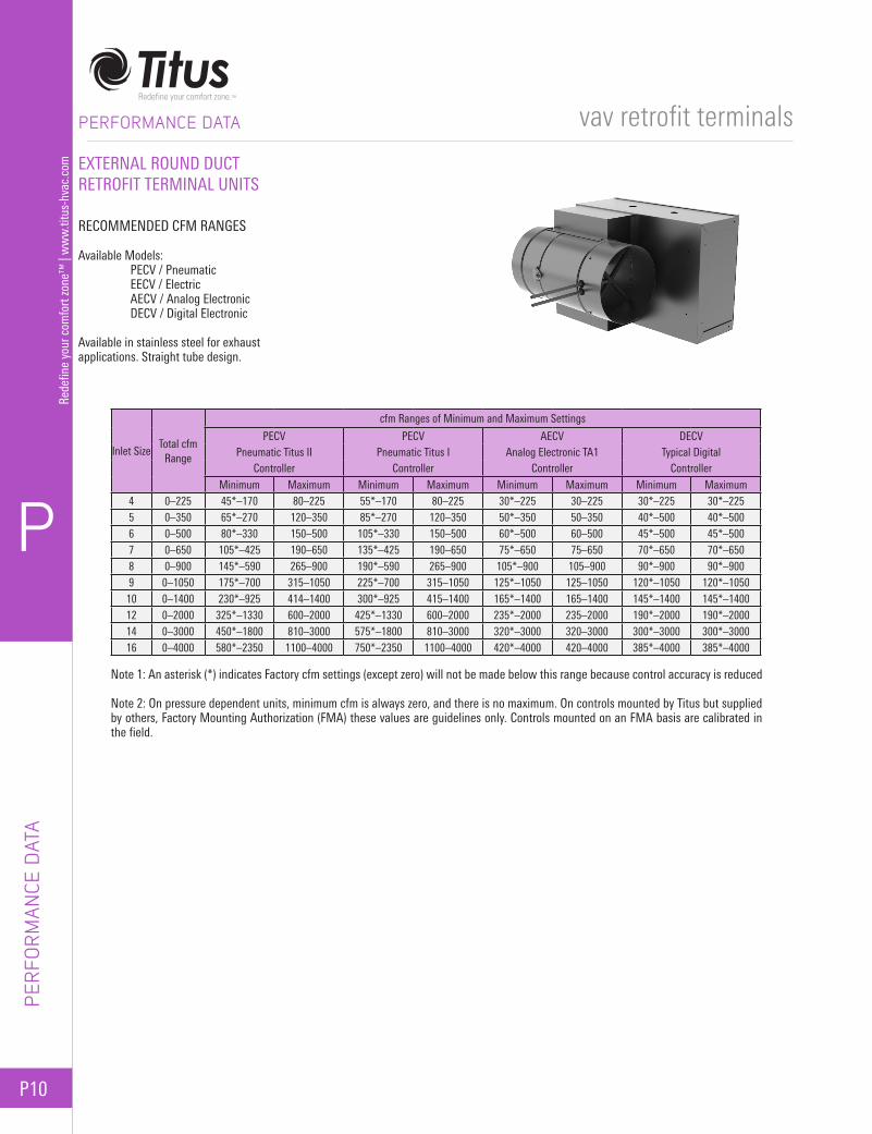
EXTERNAL ROUND DUCT RETROFIT TERMINAL UNITS
RECOMMENDED CFM RANGES
Available Models: PECV / Pneumatic EECV / Electric AECV / Analog Electronic DECV / Digital Electronic
Available in stainless steel for exhaust applications. Straight tube design.
Inlet SizeTotal cfm
Range
cfm Ranges of Minimum and Maximum Settings
PECV PECV AECV DECVPneumatic Titus II Pneumatic Titus I Analog Electronic TA1 Typical Digital
Controller Controller Controller ControllerMinimum Maximum Minimum Maximum Minimum Maximum Minimum Maximum
4 0–225 45*–170 80–225 55*–170 80–225 30*–225 30–225 30*–225 30*–2255 0–350 65*–270 120–350 85*–270 120–350 50*–350 50–350 40*–500 40*–5006 0–500 80*–330 150–500 105*–330 150–500 60*–500 60–500 45*–500 45*–5007 0–650 105*–425 190–650 135*–425 190–650 75*–650 75–650 70*–650 70*–6508 0–900 145*–590 265–900 190*–590 265–900 105*–900 105–900 90*–900 90*–9009 0–1050 175*–700 315–1050 225*–700 315–1050 125*–1050 125–1050 120*–1050 120*–105010 0–1400 230*–925 414–1400 300*–925 415–1400 165*–1400 165–1400 145*–1400 145*–140012 0–2000 325*–1330 600–2000 425*–1330 600–2000 235*–2000 235–2000 190*–2000 190*–200014 0–3000 450*–1800 810–3000 575*–1800 810–3000 320*–3000 320–3000 300*–3000 300*–300016 0–4000 580*–2350 1100–4000 750*–2350 1100–4000 420*–4000 420–4000 385*–4000 385*–4000
Note 1: An asterisk (*) indicates Factory cfm settings (except zero) will not be made below this range because control accuracy is reduced
Note 2: On pressure dependent units, minimum cfm is always zero, and there is no maximum. On controls mounted by Titus but supplied by others, Factory Mounting Authorization (FMA) these values are guidelines only. Controls mounted on an FMA basis are calibrated in the field.
P
P11
Redefine your comfort zone™
| ww
w.titus-hvac.com
vav retrofit terminals
PERFORM
ANCE D
ATA
PERFORMANCE DATA
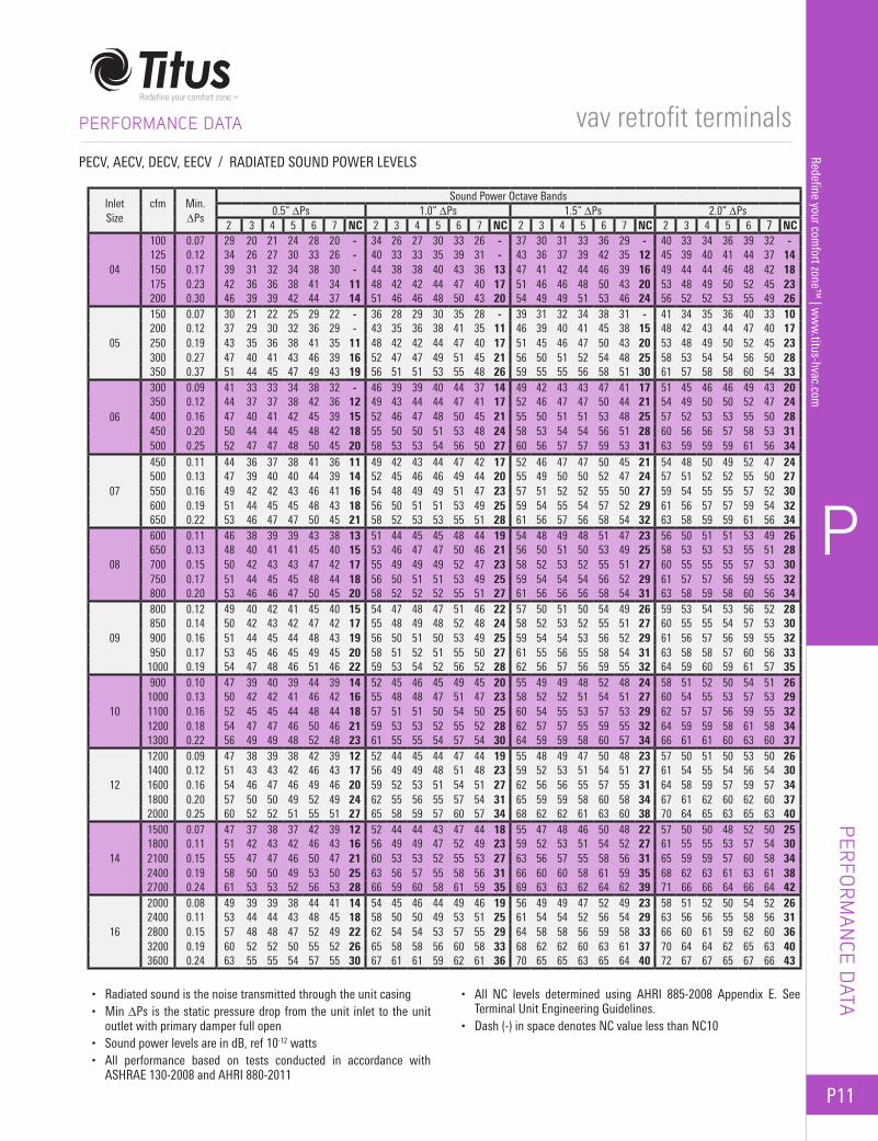
PECV, AECV, DECV, EECV / RADIATED SOUND POWER LEVELS
• Radiated sound is the noise transmitted through the unit casing• Min ∆Ps is the static pressure drop from the unit inlet to the unit
outlet with primary damper full open• Sound power levels are in dB, ref 10-12 watts• All performance based on tests conducted in accordance with
ASHRAE 130-2008 and AHRI 880-2011
• All NC levels determined using AHRI 885-2008 Appendix E. See Terminal Unit Engineering Guidelines.
• Dash (-) in space denotes NC value less than NC10
InletSize
cfm
Min.∆Ps
Sound Power Octave Bands0.5” ∆Ps 1.0” ∆Ps 1.5” ∆Ps 2.0” ∆Ps
2 3 4 5 6 7 NC 2 3 4 5 6 7 NC 2 3 4 5 6 7 NC 2 3 4 5 6 7 NC
04
100 0.07 29 20 21 24 28 20 - 34 26 27 30 33 26 - 37 30 31 33 36 29 - 40 33 34 36 39 32 -125 0.12 34 26 27 30 33 26 - 40 33 33 35 39 31 - 43 36 37 39 42 35 12 45 39 40 41 44 37 14150 0.17 39 31 32 34 38 30 - 44 38 38 40 43 36 13 47 41 42 44 46 39 16 49 44 44 46 48 42 18175 0.23 42 36 36 38 41 34 11 48 42 42 44 47 40 17 51 46 46 48 50 43 20 53 48 49 50 52 45 23200 0.30 46 39 39 42 44 37 14 51 46 46 48 50 43 20 54 49 49 51 53 46 24 56 52 52 53 55 49 26
05
150 0.07 30 21 22 25 29 22 - 36 28 29 30 35 28 - 39 31 32 34 38 31 - 41 34 35 36 40 33 10200 0.12 37 29 30 32 36 29 - 43 35 36 38 41 35 11 46 39 40 41 45 38 15 48 42 43 44 47 40 17250 0.19 43 35 36 38 41 35 11 48 42 42 44 47 40 17 51 45 46 47 50 43 20 53 48 49 50 52 45 23300 0.27 47 40 41 43 46 39 16 52 47 47 49 51 45 21 56 50 51 52 54 48 25 58 53 54 54 56 50 28350 0.37 51 44 45 47 49 43 19 56 51 51 53 55 48 26 59 55 55 56 58 51 30 61 57 58 58 60 54 33
06
300 0.09 41 33 33 34 38 32 - 46 39 39 40 44 37 14 49 42 43 43 47 41 17 51 45 46 46 49 43 20350 0.12 44 37 37 38 42 36 12 49 43 44 44 47 41 17 52 46 47 47 50 44 21 54 49 50 50 52 47 24400 0.16 47 40 41 42 45 39 15 52 46 47 48 50 45 21 55 50 51 51 53 48 25 57 52 53 53 55 50 28450 0.20 50 44 44 45 48 42 18 55 50 50 51 53 48 24 58 53 54 54 56 51 28 60 56 56 57 58 53 31500 0.25 52 47 47 48 50 45 20 58 53 53 54 56 50 27 60 56 57 57 59 53 31 63 59 59 59 61 56 34
07
450 0.11 44 36 37 38 41 36 11 49 42 43 44 47 42 17 52 46 47 47 50 45 21 54 48 50 49 52 47 24500 0.13 47 39 40 40 44 39 14 52 45 46 46 49 44 20 55 49 50 50 52 47 24 57 51 52 52 55 50 27550 0.16 49 42 42 43 46 41 16 54 48 49 49 51 47 23 57 51 52 52 55 50 27 59 54 55 55 57 52 30600 0.19 51 44 45 45 48 43 18 56 50 51 51 53 49 25 59 54 55 54 57 52 29 61 56 57 57 59 54 32650 0.22 53 46 47 47 50 45 21 58 52 53 53 55 51 28 61 56 57 56 58 54 32 63 58 59 59 61 56 34
08
600 0.11 46 38 39 39 43 38 13 51 44 45 45 48 44 19 54 48 49 48 51 47 23 56 50 51 51 53 49 26650 0.13 48 40 41 41 45 40 15 53 46 47 47 50 46 21 56 50 51 50 53 49 25 58 53 53 53 55 51 28700 0.15 50 42 43 43 47 42 17 55 49 49 49 52 47 23 58 52 53 52 55 51 27 60 55 55 55 57 53 30750 0.17 51 44 45 45 48 44 18 56 50 51 51 53 49 25 59 54 54 54 56 52 29 61 57 57 56 59 55 32800 0.20 53 46 46 47 50 45 20 58 52 52 52 55 51 27 61 56 56 56 58 54 31 63 58 59 58 60 56 34
09
800 0.12 49 40 42 41 45 40 15 54 47 48 47 51 46 22 57 50 51 50 54 49 26 59 53 54 53 56 52 28850 0.14 50 42 43 42 47 42 17 55 48 49 48 52 48 24 58 52 53 52 55 51 27 60 55 55 54 57 53 30900 0.16 51 44 45 44 48 43 19 56 50 51 50 53 49 25 59 54 54 53 56 52 29 61 56 57 56 59 55 32950 0.17 53 45 46 45 49 45 20 58 51 52 51 55 50 27 61 55 56 55 58 54 31 63 58 58 57 60 56 331000 0.19 54 47 48 46 51 46 22 59 53 54 52 56 52 28 62 56 57 56 59 55 32 64 59 60 59 61 57 35
10
900 0.10 47 39 40 39 44 39 14 52 45 46 45 49 45 20 55 49 49 48 52 48 24 58 51 52 50 54 51 261000 0.13 50 42 42 41 46 42 16 55 48 48 47 51 47 23 58 52 52 51 54 51 27 60 54 55 53 57 53 291100 0.16 52 45 45 44 48 44 18 57 51 51 50 54 50 25 60 54 55 53 57 53 29 62 57 57 56 59 55 321200 0.18 54 47 47 46 50 46 21 59 53 53 52 55 52 28 62 57 57 55 59 55 32 64 59 59 58 61 58 341300 0.22 56 49 49 48 52 48 23 61 55 55 54 57 54 30 64 59 59 58 60 57 34 66 61 61 60 63 60 37
12
1200 0.09 47 38 39 38 42 39 12 52 44 45 44 47 44 19 55 48 49 47 50 48 23 57 50 51 50 53 50 261400 0.12 51 43 43 42 46 43 17 56 49 49 48 51 48 23 59 52 53 51 54 51 27 61 54 55 54 56 54 301600 0.16 54 46 47 46 49 46 20 59 52 53 51 54 51 27 62 56 56 55 57 55 31 64 58 59 57 59 57 341800 0.20 57 50 50 49 52 49 24 62 55 56 55 57 54 31 65 59 59 58 60 58 34 67 61 62 60 62 60 372000 0.25 60 52 52 51 55 51 27 65 58 59 57 60 57 34 68 62 62 61 63 60 38 70 64 65 63 65 63 40
14
1500 0.07 47 37 38 37 42 39 12 52 44 44 43 47 44 18 55 47 48 46 50 48 22 57 50 50 48 52 50 251800 0.11 51 42 43 42 46 43 16 56 49 49 47 52 49 23 59 52 53 51 54 52 27 61 55 55 53 57 54 302100 0.15 55 47 47 46 50 47 21 60 53 53 52 55 53 27 63 56 57 55 58 56 31 65 59 59 57 60 58 342400 0.19 58 50 50 49 53 50 25 63 56 57 55 58 56 31 66 60 60 58 61 59 35 68 62 63 61 63 61 382700 0.24 61 53 53 52 56 53 28 66 59 60 58 61 59 35 69 63 63 62 64 62 39 71 66 66 64 66 64 42
16
2000 0.08 49 39 39 38 44 41 14 54 45 46 44 49 46 19 56 49 49 47 52 49 23 58 51 52 50 54 52 262400 0.11 53 44 44 43 48 45 18 58 50 50 49 53 51 25 61 54 54 52 56 54 29 63 56 56 55 58 56 312800 0.15 57 48 48 47 52 49 22 62 54 54 53 57 55 29 64 58 58 56 59 58 33 66 60 61 59 62 60 363200 0.19 60 52 52 50 55 52 26 65 58 58 56 60 58 33 68 62 62 60 63 61 37 70 64 64 62 65 63 403600 0.24 63 55 55 54 57 55 30 67 61 61 59 62 61 36 70 65 65 63 65 64 40 72 67 67 65 67 66 43
P12
P
Rede
fine
your
com
fort
zone
™ |
ww
w.ti
tus-
hvac
.com
vav retrofit terminals
PERF
ORM
ANCE
DAT
A
PERFORMANCE DATA
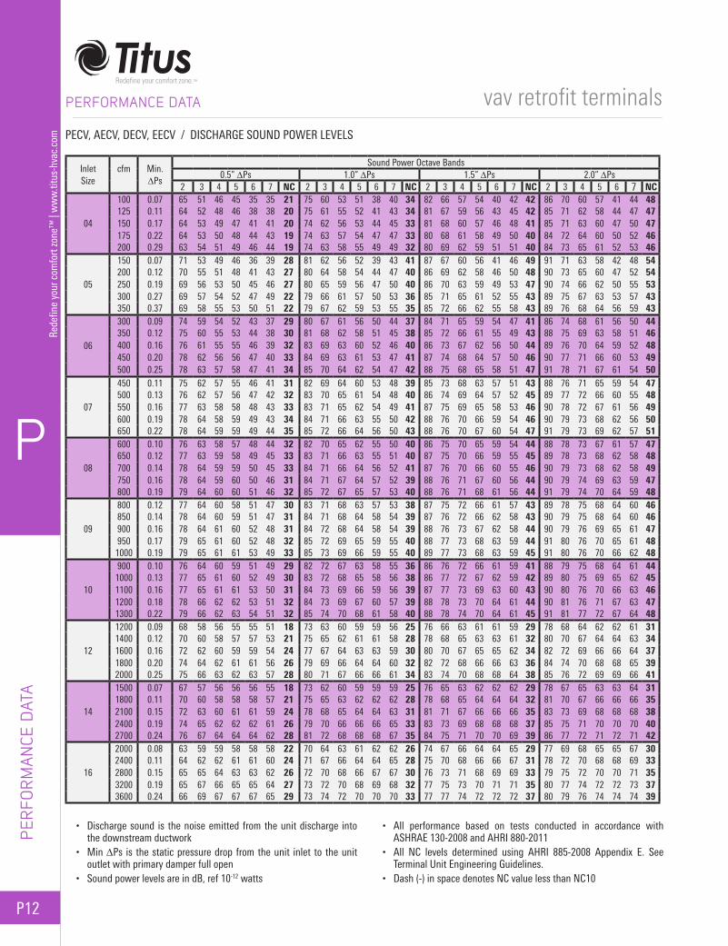
• Discharge sound is the noise emitted from the unit discharge into the downstream ductwork
• Min ∆Ps is the static pressure drop from the unit inlet to the unit outlet with primary damper full open
• Sound power levels are in dB, ref 10-12 watts
• All performance based on tests conducted in accordance with ASHRAE 130-2008 and AHRI 880-2011
• All NC levels determined using AHRI 885-2008 Appendix E. See Terminal Unit Engineering Guidelines.
• Dash (-) in space denotes NC value less than NC10
PECV, AECV, DECV, EECV / DISCHARGE SOUND POWER LEVELS
InletSize
cfm
Min.∆Ps
Sound Power Octave Bands0.5” ∆Ps 1.0” ∆Ps 1.5” ∆Ps 2.0” ∆Ps
2 3 4 5 6 7 NC 2 3 4 5 6 7 NC 2 3 4 5 6 7 NC 2 3 4 5 6 7 NC
04
100 0.07 65 51 46 45 35 35 21 75 60 53 51 38 40 34 82 66 57 54 40 42 42 86 70 60 57 41 44 48125 0.11 64 52 48 46 38 38 20 75 61 55 52 41 43 34 81 67 59 56 43 45 42 85 71 62 58 44 47 47150 0.17 64 53 49 47 41 41 20 74 62 56 53 44 45 33 81 68 60 57 46 48 41 85 71 63 60 47 50 47175 0.22 64 53 50 48 44 43 19 74 63 57 54 47 47 33 80 68 61 58 49 50 40 84 72 64 60 50 52 46200 0.29 63 54 51 49 46 44 19 74 63 58 55 49 49 32 80 69 62 59 51 51 40 84 73 65 61 52 53 46
05
150 0.07 71 53 49 46 36 39 28 81 62 56 52 39 43 41 87 67 60 56 41 46 49 91 71 63 58 42 48 54200 0.12 70 55 51 48 41 43 27 80 64 58 54 44 47 40 86 69 62 58 46 50 48 90 73 65 60 47 52 54250 0.19 69 56 53 50 45 46 27 80 65 59 56 47 50 40 86 70 63 59 49 53 47 90 74 66 62 50 55 53300 0.27 69 57 54 52 47 49 22 79 66 61 57 50 53 36 85 71 65 61 52 55 43 89 75 67 63 53 57 43350 0.37 69 58 55 53 50 51 22 79 67 62 59 53 55 35 85 72 66 62 55 58 43 89 76 68 64 56 59 43
06
300 0.09 74 59 54 52 43 37 29 80 67 61 56 50 44 37 84 71 65 59 54 47 41 86 74 68 61 56 50 44350 0.12 75 60 55 53 44 38 30 81 68 62 58 51 45 38 85 72 66 61 55 49 43 88 75 69 63 58 51 46400 0.16 76 61 55 55 46 39 32 83 69 63 60 52 46 40 86 73 67 62 56 50 44 89 76 70 64 59 52 48450 0.20 78 62 56 56 47 40 33 84 69 63 61 53 47 41 87 74 68 64 57 50 46 90 77 71 66 60 53 49500 0.25 78 63 57 58 47 41 34 85 70 64 62 54 47 42 88 75 68 65 58 51 47 91 78 71 67 61 54 50
07
450 0.11 75 62 57 55 46 41 31 82 69 64 60 53 48 39 85 73 68 63 57 51 43 88 76 71 65 59 54 47500 0.13 76 62 57 56 47 42 32 83 70 65 61 54 48 40 86 74 69 64 57 52 45 89 77 72 66 60 55 48550 0.16 77 63 58 58 48 43 33 83 71 65 62 54 49 41 87 75 69 65 58 53 46 90 78 72 67 61 56 49600 0.19 78 64 58 59 49 43 34 84 71 66 63 55 50 42 88 76 70 66 59 54 46 90 79 73 68 62 56 50650 0.22 78 64 59 59 49 44 35 85 72 66 64 56 50 43 88 76 70 67 60 54 47 91 79 73 69 62 57 51
08
600 0.10 76 63 58 57 48 44 32 82 70 65 62 55 50 40 86 75 70 65 59 54 44 88 78 73 67 61 57 47650 0.12 77 63 59 58 49 45 33 83 71 66 63 55 51 40 87 75 70 66 59 55 45 89 78 73 68 62 58 48700 0.14 78 64 59 59 50 45 33 84 71 66 64 56 52 41 87 76 70 66 60 55 46 90 79 73 68 62 58 49750 0.16 78 64 59 60 50 46 31 84 71 67 64 57 52 39 88 76 71 67 60 56 44 90 79 74 69 63 59 47800 0.19 79 64 60 60 51 46 32 85 72 67 65 57 53 40 88 76 71 68 61 56 44 91 79 74 70 64 59 48
09
800 0.12 77 64 60 58 51 47 30 83 71 68 63 57 53 38 87 75 72 66 61 57 43 89 78 75 68 64 60 46850 0.14 78 64 60 59 51 47 31 84 71 68 64 58 54 39 87 76 72 66 62 58 43 90 79 75 68 64 60 46900 0.16 78 64 61 60 52 48 31 84 72 68 64 58 54 39 88 76 73 67 62 58 44 90 79 76 69 65 61 47950 0.17 79 65 61 60 52 48 32 85 72 69 65 59 55 40 88 77 73 68 63 59 44 91 80 76 70 65 61 481000 0.19 79 65 61 61 53 49 33 85 73 69 66 59 55 40 89 77 73 68 63 59 45 91 80 76 70 66 62 48
10
900 0.10 76 64 60 59 51 49 29 82 72 67 63 58 55 36 86 76 72 66 61 59 41 88 79 75 68 64 61 441000 0.13 77 65 61 60 52 49 30 83 72 68 65 58 56 38 86 77 72 67 62 59 42 89 80 75 69 65 62 451100 0.16 77 65 61 61 53 50 31 84 73 69 66 59 56 39 87 77 73 69 63 60 43 90 80 76 70 66 63 461200 0.18 78 66 62 62 53 51 32 84 73 69 67 60 57 39 88 78 73 70 64 61 44 90 81 76 71 67 63 471300 0.22 79 66 62 63 54 51 32 85 74 70 68 61 58 40 88 78 74 70 64 61 45 91 81 77 72 67 64 48
12
1200 0.09 68 58 56 55 55 51 18 73 63 60 59 59 56 25 76 66 63 61 61 59 29 78 68 64 62 62 61 311400 0.12 70 60 58 57 57 53 21 75 65 62 61 61 58 28 78 68 65 63 63 61 32 80 70 67 64 64 63 341600 0.16 72 62 60 59 59 54 24 77 67 64 63 63 59 30 80 70 67 65 65 62 34 82 72 69 66 66 64 371800 0.20 74 64 62 61 61 56 26 79 69 66 64 64 60 32 82 72 68 66 66 63 36 84 74 70 68 68 65 392000 0.25 75 66 63 62 63 57 28 80 71 67 66 66 61 34 83 74 70 68 68 64 38 85 76 72 69 69 66 41
14
1500 0.07 67 57 56 56 56 55 18 73 62 60 59 59 59 25 76 65 63 62 62 62 29 78 67 65 63 63 64 311800 0.11 70 60 58 58 58 57 21 75 65 63 62 62 62 28 78 68 65 64 64 64 32 81 70 67 66 66 66 352100 0.15 72 63 60 61 61 59 24 78 68 65 64 64 63 31 81 71 67 66 66 66 35 83 73 69 68 68 68 382400 0.19 74 65 62 62 62 61 26 79 70 66 66 66 65 33 83 73 69 68 68 68 37 85 75 71 70 70 70 402700 0.24 76 67 64 64 64 62 28 81 72 68 68 68 67 35 84 75 71 70 70 69 39 86 77 72 71 72 71 42
16
2000 0.08 63 59 59 58 58 58 22 70 64 63 61 62 62 26 74 67 66 64 64 65 29 77 69 68 65 65 67 302400 0.11 64 62 62 61 61 60 24 71 67 66 64 64 65 28 75 70 68 66 66 67 31 78 72 70 68 68 69 332800 0.15 65 65 64 63 63 62 26 72 70 68 66 67 67 30 76 73 71 68 69 69 33 79 75 72 70 70 71 353200 0.19 65 67 66 65 65 64 27 73 72 70 68 69 68 32 77 75 73 70 71 71 35 80 77 74 72 72 73 373600 0.24 66 69 67 67 67 65 29 73 74 72 70 70 70 33 77 77 74 72 72 72 37 80 79 76 74 74 74 39

P
P13
Redefine your comfort zone™
| ww
w.titus-hvac.com
vav retrofit terminals
Titus Slide-In Retrofit Terminals convert those old constant volume systems to modern and energy efficient variable air volume.
Slide-in retrofit terminals are designed to transform inefficient constant volume systems to present day variable volume systems with very low installation costs. The resulting performance of a system incorporating Titus QCV series terminals approaches that of a VAV system using ESV series single duct terminals.
With the simple installation method, conversion costs are minimized. The installer simply cuts a rectangular hole in the side of the duct, cuts away the insulation (if present), slides the unit into the duct, and screws the mounting plate to the side of the duct.
Take a look at many of the unique features of a Titus QCV series retrofit terminal!
Available in many different sizes, the QCV series units will mount in almost any square size duct.
Damper position indicator is formed into the end of the shaft for easy monitoring of damper position.
Field convertible linkage (pneumatic controls) allows NO/NC changeover without actuator removal.
The casing can be configured to mount on either the right side or left side of the existing duct.
Formed flanges provide added duct stiffness at the insertion point.
Shown here with the TITUS I pneumatic velocity controller, the QCV is also available with analog electronic and direct digitalelectronic controls.
AeroCrossTM multi-point, center averaging sensor amplifies flowsignal for best control of low flow rates. Center averaging feature
provides signal accuracy, regardlessof inlet duct configuration.
Damper is constructed of 16-gauge galvanized steel to prevent vibrationunder high pressure conditions.
Elastomer seals on the edges of the damper blades allowlow leakage during full shut off.
PQCV
Overview - QCV Slide-In SeriesFEATURES AND BENEFITS
SLIDE-IN
SERIES

P14
P
Rede
fine
your
com
fort
zone
™ |
ww
w.ti
tus-
hvac
.com
vav retrofit terminals
APPL
ICAT
ION
S
APPLICATIONS
LOW PRESSURE, CONSTANT VOLUME REHEAT SYSTEMCold air from the central air handler is distributed through the original duct system. The QCV retrofit terminals convert the system to variable air volume operation.
Each QCV terminal is signaled by a direct acting thermostat. In the pneumatic example shown in the diagram, the pressure independent minimum airflow is set at a thermostat output pressure of 8 psi or less, while the maximum is set at 13 psi or greater.
The existing reheat coil in each zone is actuated on a fall in room temperature as the thermostat output decreases from 8 to 3 psi.
MULTI-ZONE SYSTEMHot or cold air from the central multi-zone air handler is distributed through the original zone ducts. The QCV retrofit terminals convert the system to variable air volume operation.
The multi-zone dampers provide a mixed airflow temperature of air at minimum airflow. The PQCV valves provide VAV and pressure independent flow. Very little work is required to convert a multi-zone pressure dependent set of zones to an energy saving series of VAV zones. Each zone now has fixed maximum and minimum airflow without system hunting.
DUAL DUCT SYSTEMHot and cold air from the central air handler is distributed through the original supply ducts and terminals. The QCV retrofit terminals convert the system to variable air volume operation.
The mechanical constant volume regulator is removed from each existing terminal, while a QCV is installed in the discharge duct. A direct acting thermostat controls both the PQCV and the modulating splitter damper in the existing terminal.
On a rise in room temperature, the PQCV reduces the hot airflow. At the minimum airflow setting, the damper in the existing unit, which in this example has an 8 to 13 psi actuator, begins to modulate and mixing occurs. A further temperature rise increases the cold airflow to the maximum. Since the total air volume is reduced, the fan may need to be slowed down.
Low Pressure, Constant volume Reheat System ExampleExistingReheatCoils
TITUSPQCVs
Cold Air
Multi-Zone System Example
Dual Duct System Example
Max.
Min.
Room Temperature Increase
Hot Water Flow
cfm
Incr
ease
ReturnAir
OutsideAir
PneumaticActuator8-13 psi
PneumaticActuator8-13 psi
Fan SpeedControl
TITUS PQCV withECT-3LD Control Kit
T
T
S.P.
HotCoil N. Open
N. ClosedColdCoil
HotCoil
ColdCoil
Max CLGMax HTG
Room Temperature Increase
cfm
Incr
ease
Remove Existing MechanicalConstant Volume Regulator
Cold Air
To ExistingDamperActuator
TITUSPQCV
ECT-3LDControl Kit
20 psiMain AirM
Direct ActingThermostat T
Max CLGMax HTG
Room Temperature Increase
cfm
Incr
ease

P
P15
Redefine your comfort zone™
| ww
w.titus-hvac.com
vav retrofit terminals
DIM
ENSIO
NS
DIMENSIONS
Available Model: QCV Series
Unit/ Damper
Size
cfm Range
Max cfm Range
Available Duct Sizes*Width W Height H
J(18x12)
0 1000 18, 20, 22, 24, 26, 28 12to to 18, 20, 22, 24, 26, 28 14
2400 2400 18, 20, 22, 24, 26, 28 16
K(20x14)
0 1350 20, 22, 24, 26, 28, 30 14to to 20, 22, 24, 26, 28, 30 16
3800 3800 20, 22, 24, 26, 28, 30 18
L(30x12)
0 1800 30, 32, 34, 36 12to to 30, 32, 34, 36 14
5400 5400 30, 32, 34, 36 16
M(22x16)
0 1750 22, 24, 26, 28, 30, 32, 34, 36 16to to 22, 24, 26, 28, 30, 32, 34, 36 18
5400 5400 22, 24, 26, 28, 30, 32, 34, 36 20
N(24x18)
0to
6700
2300to
6700
24, 26, 28, 30, 32, 34, 36 1824, 26, 28, 30, 32, 34, 36 2024, 26, 28, 30, 32, 34, 36 2424, 26, 28, 30, 32, 34, 36 26
P(30x20)
0 4000 30, 32, 34, 36, 38, 40, 42, 44, 46 20to to 30, 32, 34, 36, 38, 40, 42, 44, 46 24
10000 10000 30, 32, 34, 36, 38, 40, 42, 44, 46 26
R(40x20)
0 5000 40, 42, 44, 46, 48, 50, 52 20to to 40, 42, 44, 46, 48, 50, 52 24
15000 15000 40, 42, 44, 46, 48, 50, 52 26
QCV SERIES / AVAILABLE DUCT SIZES*
Note 1: The cfm Range column shows ranges from lowest minimum setting to highest maximum setting for pneumatic controls.
Note 2: The column, Max cfm Range shows the range of maximum cfm settings, for pneumatic controls.
* This is only a sampling of sizes available for the QCV Series. Any duct size larger than the damper size can be built.
Orifice plate is undersized ¼” foreasy installation. Additional gasketmust be field supplied to assure a tight seal.
AeroCrossTM,multi-point, centeraveraging velocity sensor
Gasket
Gasket
Airflow
10½”
17”
6”
12¼”
18”
H + 1/8”
ControlEnclosure
Opening in duct by others
Mounting Plate
W**
H**
Unit/ Damper
Size
cfm Range
Max cfm Range
Available Duct Sizes*Width W Height H
A(5x5)
0 100 5, 6, 8, 10, 12 5to to 6, 8, 10, 12 6
200 200 6, 8, 10, 12 8
B(6x6)
0 150 6, 8, 10, 12, 14 6to to 8, 10, 12, 14 8
300 300 8, 10, 12, 14 10
C(8x6)
0 20 8, 10, 12, 14, 16 6to to 8, 10, 12, 14, 16 8
400 400 8, 10, 12, 14, 16 10
D(10x8)
0to
700
350to
700
10, 12, 14, 16, 18 810, 12, 14, 16, 18 1010, 12, 14, 16, 18 1210, 12, 14, 16, 18 14
E(14x8)
0 500 14, 16, 18, 20, 22, 24 8to to 14, 16, 18, 20, 22, 24 10
1000 1000 14, 16, 18, 20, 22, 24 12
F(18x6)
0 500 18, 20, 22, 24, 26 6to to 18, 20, 22, 24, 26 8
1000 1000 18, 20, 22, 24, 26 10
G(12x10)
0 600 12, 14, 16, 18, 20, 22 10to to 12, 14, 16, 18, 20, 22 12
1100 1100 12, 14, 16, 18, 20, 22 14
H(18x10)
0 800 18, 20, 22, 24, 26, 28, 30 10to to 18, 20, 22, 24, 26, 28, 30 12
1900 1900 18, 20, 22, 24, 26, 28, 30 14
Note 1: H and W represents outside duct dimension.
Note 2: Analog/digital (AQCV/DQCV) shown. Contact your Titus representative for control enclosure location and dimensions. Available with pneumatic controls.

P16
P
Rede
fine
your
com
fort
zone
™ |
ww
w.ti
tus-
hvac
.com
vav retrofit terminals
PERF
ORM
ANCE
DAT
A
PERFORMANCE DATA
SLIDE-IN RETROFIT TERMINAL UNITS
RECOMMENDED CFM RANGES
Available Models: PQCV / Pneumatic AQCV / Analog Electronic DQCV / Digital Electronic
• Total cfm range refers to the overall range of adjustment of the pneumatic velocity controller, from the lowest MIN setting to the highest MAX setting
• Minimum cfm range refers to the range of adjustment of the MIN setting of the pneumatic velocity controller
• Maximum cfm range refers to the range of adjustment of the MAX setting of the pneumatic velocity controller
Inlet SizeDamper
SizeTotal cfm
Range
cfm Ranges of Minimum and Maximum SettingsPQCV Pneumatic TITUS II AQCV Analog Electronic DQCV Typical Digital
Controller Controller ControllerMinimum Maximum Minimum Maximum Minimum Maximum
A 5 x 5 0–200 *55–200 100–200 *55–200 55–200 *55–200 55–200B 6 x 6 0–300 *80–300 100–200 *80–300 80–300 *80–300 80–300C 8 x 6 0–400 *110–400 195–400 *110–400 110–400 *110–400 110–400D 10 x 8 0–700 *180–700 320–700 *180–700 180–700 *180–700 180–700E 14 x 8 0–1000 *260–1000 475–1000 *260–1000 260–1000 *260–1000 260–1000F 18 x 6 0–1000 *250–1000 455–1000 *250–1000 250–1000 *250–1000 250–1000G 12 x 10 0–1100 *280–1100 510–1200 280–1100 280–1100 *280–1100 280–1100H 18 x 10 0–1900 *435–1775 795–2000 *435–1900 435–1900 *435–1900 435–1900J 18 x 12 0–2400 *540–2180 980–2400 *540–2400 540–2400 *540–2400 540–2400K 20 x 14 0–3800 *725–2945 1320–3800 *725–3800 725–3800 *725–3800 725–3800L 30 x 12 0–5400 *980–3975 1780–5500 *980–5400 980–5400 *980–5400 980–5400M 22 x 16 0–5400 *970–3870 1735–5500 *970–5400 970–5400 *970–5400 970–5400N 24 x18 0–6700 *1220–4975 2225–6700 *1220–6700 1220–6700 *1220–6700 1220–6700P 30 x 20 0–10000 *1860–7500 3400–10000 *1860–10000 1860–10000 *1860–10000 1860–10000R 40 x 20 0–15000 *2750–11000 5000–15000 *2750–15000 2750–15000 *2750–15000 2750–15000
Note: An asterisk (*) indicates factory settings (except zero) will not be made below this range because control accuracy would be reduced.
P
P17
Redefine your comfort zone™
| ww
w.titus-hvac.com
vav retrofit terminals
PERFORM
ANCE D
ATA
PERFORMANCE DATA
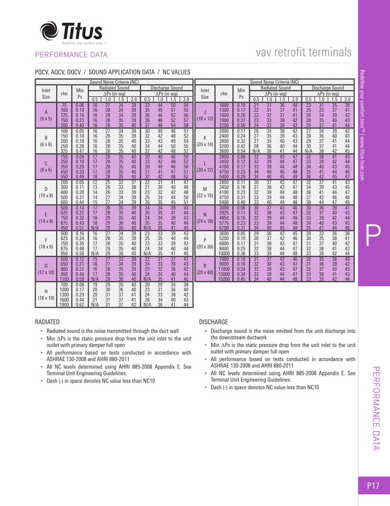
• Radiated sound is the noise transmitted through the duct wall• Min ∆Ps is the static pressure drop from the unit inlet to the unit
outlet with primary damper full open• All performance based on tests conducted in accordance with
ASHRAE 130-2008 and AHRI 880-2011• All NC levels determined using AHRI 885-2008 Appendix E. See
Terminal Unit Engineering Guidelines.• Dash (-) in space denotes NC value less than NC10
• Discharge sound is the noise emitted from the unit discharge into the downstream ductwork
• Min ∆Ps is the static pressure drop from the unit inlet to the unit outlet with primary damper full open
• All performance based on tests conducted in accordance with ASHRAE 130-2008 and AHRI 880-2011
• All NC levels determined using AHRI 885-2008 Appendix E. See Terminal Unit Engineering Guidelines.
• Dash (-) in space denotes NC value less than NC10
PQCV, AQCV, DQCV / SOUND APPLICATION DATA / NC VALUES
Sound Noise Criteria (NC)
InletSize
cfmMinPs
Radiated Sound Discharge Sound∆Ps (in wg) ∆Ps (in wg)
0.5 1.0 1.5 2.0 0.5 1.0 1.5 2.0
A(5 x 5)
75 0.06 16 27 34 39 33 44 50 54100 0.10 16 28 34 39 35 45 51 55125 0.16 16 28 34 39 36 46 52 56150 0.23 16 28 35 39 36 46 52 57200 0.40 16 28 35 40 37 48 54 58
B(6 x 6)
100 0.05 16 27 34 39 30 40 46 51150 0.10 16 28 35 39 32 42 48 52200 0.18 16 28 35 40 33 43 49 54250 0.28 16 28 35 40 34 44 50 55325 0.47 16 28 35 40 32 42 48 52
C(8 x 6)
150 0.04 17 28 35 40 30 40 46 50250 0.10 17 28 35 40 33 42 48 52350 0.20 17 28 35 40 30 40 46 50450 0.33 17 28 35 40 31 41 47 51550 0.49 18 28 35 40 32 42 48 52
D(10 x 8)
200 0.05 12 25 32 37 22 31 41 47300 0.11 13 26 33 38 21 30 40 46400 0.20 14 26 33 39 23 32 42 48500 0.31 14 27 34 39 25 34 44 50600 0.44 15 27 34 39 26 35 45 51
E(14 x 8)
500 0.14 17 28 35 39 24 34 39 43625 0.22 17 28 35 40 26 35 41 44750 0.32 18 29 35 40 24 34 39 43875 0.43 18 29 36 40 25 35 40 44950 0.51 N/A 29 36 40 N/A 35 41 45
F(18 x 6)
500 0.16 16 27 34 39 23 33 39 43625 0.24 16 28 35 39 25 35 40 44750 0.35 17 28 35 40 23 33 39 43875 0.48 17 29 35 40 24 34 40 44950 0.56 N/A 29 36 40 N/A 35 41 45
G(12 x 10)
500 0.12 15 27 33 38 22 31 37 41650 0.21 16 27 34 39 24 33 39 43800 0.31 16 28 35 39 23 32 38 42950 0.44 17 28 35 40 24 34 40 441100 0.59 N/A 29 36 40 N/A 35 41 45
H(18 x 10)
700 0.08 19 29 35 40 20 29 34 381000 0.17 20 30 36 40 23 31 36 401300 0.29 20 31 37 41 24 33 38 421600 0.44 21 31 37 41 26 34 40 431900 0.62 N/A 31 37 42 N/A 36 41 44
Sound Noise Criteria (NC)
InletSize
cfmMinPs
Radiated Sound Discharge Sound∆Ps (in wg) ∆Ps (in wg)
0.5 1.0 1.5 2.0 0.5 1.0 1.5 2.0
J(18 x 12)
1000 0.10 21 31 36 40 23 31 35 391300 0.17 22 31 37 41 25 33 37 411600 0.26 23 32 37 41 26 34 39 421900 0.37 23 33 38 42 28 35 40 432200 0.50 24 33 38 42 29 37 41 44
K(20 x 14)
2000 0.17 26 34 38 42 27 34 39 422400 0.24 27 35 39 43 28 36 40 432800 0.32 27 35 40 43 29 37 41 443200 0.42 28 36 40 44 30 37 41 443600 0.54 N/A 36 41 44 N/A 38 42 45
L(30 x 12)
2800 0.08 32 38 43 47 32 38 41 433450 0.12 32 39 44 47 33 39 42 444100 0.17 33 39 44 48 34 40 43 454750 0.23 34 40 45 48 35 41 44 465400 0.29 34 40 45 49 36 42 45 47
M(22 x 16)
2800 0.11 30 37 43 47 32 37 41 433450 0.16 31 38 43 47 34 39 43 454100 0.23 32 38 44 48 36 41 44 474750 0.31 33 39 44 48 37 42 46 485400 0.40 33 40 44 48 38 44 47 49
N(24 x 18)
3000 0.06 30 37 43 46 30 36 39 413925 0.11 32 38 43 47 32 37 40 434850 0.16 32 39 44 48 33 39 42 445775 0.23 33 39 44 48 34 40 43 456700 0.31 34 40 45 48 35 41 44 46
P(20 x 30)
3600 0.05 29 36 42 45 28 33 36 385200 0.10 30 37 42 46 30 35 38 416800 0.17 31 38 43 47 31 37 40 428400 0.25 32 38 44 47 32 38 41 4310000 0.36 33 39 44 48 33 39 42 44
R(20 x 40)
7000 0.10 31 37 42 46 30 35 38 409000 0.16 32 38 43 47 31 36 39 42
11000 0.24 33 39 43 47 32 37 40 4313000 0.34 33 39 44 47 33 38 41 4315000 0.45 34 40 44 48 33 39 42 44
RADIATED DISCHARGE
P18
P
Rede
fine
your
com
fort
zone
™ |
ww
w.ti
tus-
hvac
.com
vav retrofit terminals
Titus Internal Retrofit Terminals convert those old mechanically regulated terminals to energy efficient VAV terminals!
Existing constant volume systems retrofitted to variable air volume conserve energy by reducing reheat requirements, reducing refrigeration loads and reducing fan horsepower by taking advantage of building load diversity. Titus provides an easy, effective means to retrofit existing mechanical constant volume terminals without replacing the existing terminal or interrupting ductwork.
Titus internally mounted, or ECT series, terminals are the most unique line of retrofit devices in the HVAC industry. Specifically designed to quickly replace mechanical regulators in existing terminals, each ECT series valve is unique. By replacing the mechanical regulators with ECT valves, the
inefficient constant volume system is transformed into an energy saving, comfort providing variable volume system.
Mechanically regulated terminals were produced by many different manufacturers over the years, including Titus. Today, a different model of ECT series retrofit variable air volume valve is used to replace the old mechanical regulators for each different manufacturer of terminals. Best of all, this is done with very little effort since each retrofit valve is designed to be installed while the supply air system is still running and without removing the existing terminals.
Each ECT series valve is designed for maximum efficiency in operation and installation. Let’s look at some of the features found in Titus ECT series internal retrofit terminals.
Overview - Special Purpose and Internal SeriesFEATURES AND BENEFITS
SPEC
IAL
PURP
OSE
& IN
TERN
AL
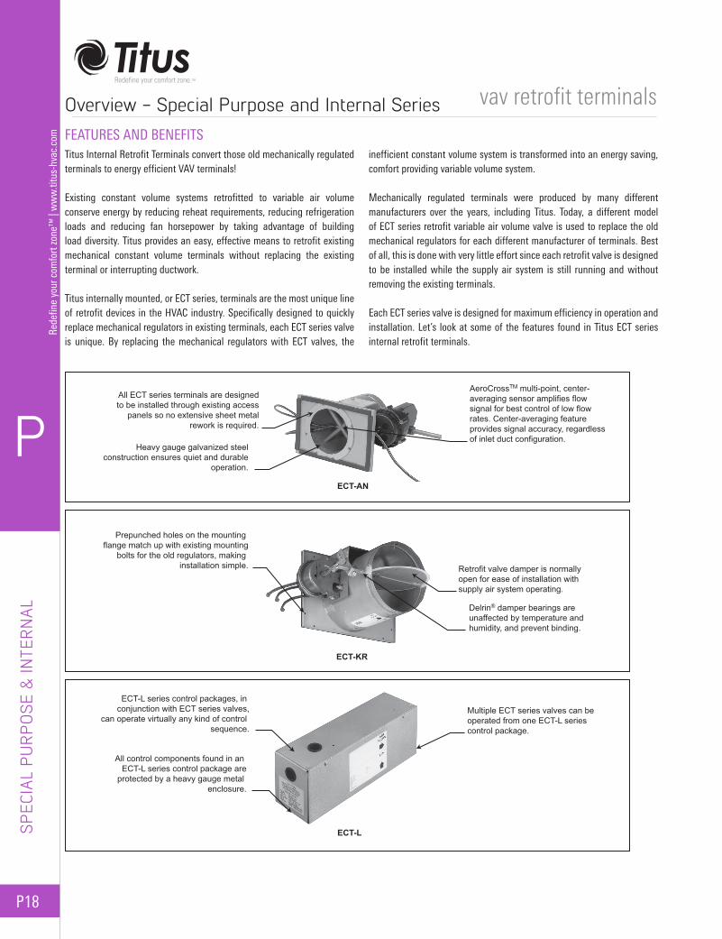
AeroCrossTM multi-point, center-averaging sensor amplifies flow signal for best control of low flow rates. Center-averaging feature provides signal accuracy, regardless of inlet duct configuration.
All ECT series terminals are designedto be installed through existing access
panels so no extensive sheet metalrework is required.
Heavy gauge galvanized steelconstruction ensures quiet and durable
operation.
ECT-AN
Retrofit valve damper is normally open for ease of installation with supply air system operating.
Delrin® damper bearings are unaffected by temperature and humidity, and prevent binding.
Prepunched holes on the mounting flange match up with existing mounting
bolts for the old regulators, making installation simple.
ECT-KR
Multiple ECT series valves can be operated from one ECT-L series control package.
ECT-L series control packages, in conjunction with ECT series valves,
can operate virtually any kind of control sequence.
All control components found in an ECT-L series control package are
protected by a heavy gauge metal enclosure.
ECT-L

P
P19
Redefine your comfort zone™
| ww
w.titus-hvac.com
vav retrofit terminals
APPLICATION
S
APPLICATIONS
CONVERTING SINGLE DUCT CONSTANT VOLUME TO VAVIn the preceding diagram, the original single duct constant volume, cooling only terminal has been converted to single duct VAV cooling only. The constant volume regulators have been replaced with a Titus ECT series internal retrofit terminal. The Titus ECT-3LS pneumatic control package provides pressure independent VAV control.
CONVERTING SINGLE DUCT CONSTANT VOLUME WITH REHEAT TO VAVIn the preceding diagram, the original single duct constant volume unit with reheat has been converted to single duct VAV. The constant volume regulators have been replaced with a Titus ECT series internal retrofit terminal. The Titus ECT-3LD pneumatic control package provides pressure independent VAV control for both cooling and heating. The heating airflow increases with an increase in water flow for more accurate constant discharge air temperature.
CONVERTING DUAL DUCT CONSTANT VOLUME TO SINGLE DUCT VAV COOLINGIn the preceding diagram, the original dual duct terminal has been converted to single duct, cooling only, to serve an interior zone.
Notice that the hot duct connection has been capped. The damper is normally closed with respect to the cold air duct. Since the main control air feeds directly into the existing damper actuator, the damper goes fully open when the main control air is turned on. The Titus ECT-3LS then provides pressure independent VAV control.
Converting Single Duct Constant Volume to VAV
20 - 25 psiMain Air ECT-3LS
ECT
T‘StatMax.
Min.
Room Temperature Increase
cfm
Incr
ease
Converting Single Duct Constant Volume with Reheat to VAV
20 - 25 psiMain Air ECT-3LD
ECT
T‘Stat
Hot WaterValve
Coi
l
Max.Max.
Min.
Room Temperature Increase
Hot Water Flow
cfm
Incr
ease
Converting Dual Duct Constant Volume to Single Duct VAV Cooling
20 - 25 psiMain Air ECT-3LS
ECT
T‘Stat
Actuator
ExistingDamperActuator
Existing Dual DuctTerminal Unit
Cold Air
Cap
Max.
Min.
Room Temperature Increase
cfm
Incr
ease

P20
P
Rede
fine
your
com
fort
zone
™ |
ww
w.ti
tus-
hvac
.com
vav retrofit terminals
APPL
ICAT
ION
S
APPLICATIONS
CONVERTING DUAL DUCT CONSTANT VOLUME TO DUAL DUCT VAV, WITH MINIMUM MIX AND EQUAL TO MAXIMUM HEATING (BLENDING)In the preceding diagram, the dual duct function is retained for use in an interior or exterior zone. The Titus ECT-3LS provides pressure independent control for both cooling and heating. Cooling is variable air volume, while heating is constant air volume at the minimum cfm setting of the Titus ll controller. The original pneumatic inlet damper modulates from 100 percent cold to 100 percent hot as the thermostat calls for more heat. The Titus II start point is adjusted to 13 psi.
CONVERTING DUAL DUCT CONSTANT VOLUME TO DUAL DUCT VAV, WITH ZERO MINIMUM FLOW (NON-BLENDING)In the preceding diagram, the physical hookup is the same as in the diagram, Converting Dual Duct Volume to Single Duct VAV Cooling, except for the addition of a snap acting diverting relay with its own air supply.
Here both the reversing relay bias and the ECT-4LD start point are set at 8 psi. The ECT-4LD is also set for a minimum cfm of zero. The original dual duct unit damper snaps from 100 percent cooling to 100 percent heating at 8 psi. Below 8 psi this damper remains in full heating position, while the Titus control modulates from minimum to maximum heating cfm.
CONVERTING DUAL DUCT CONSTANT VOLUME TO DUAL DUCT VAV, WITH MINIMUM MIX AND EQUAL TO MAXIMUM FLOWS (BLENDING)In the preceding diagram, the addition of a reversing relay and a high pressure selector allows pressure independent VAV control of heating, as well as cooling, in the dual duct unit.
In this example the reversing relay bias is set at 10.5 psi. The Titus ECT-3LD is set for minimum cooling cfm at 13 psi thermostat output pressure. From 13 to 8 psi the original dual duct unit damper modulates from cooling to heating, so that there is mixing at the minimum cfm. From 8 to 3 psi the Titus control modulates from minimum to maximum heating cfm. The Titus II start point is adjusted to 13 psi.
Converting Dual Duct Constant Volume to Dual Duct VAV (Minimum Mix and Equal to Maximum Heating)
Refer to the topic, “Internal Retrofit” in this section for piping details.
20 - 25 psiMain Air
ECT-3LS
ECT
T‘Stat
Actuator
ExistingDamperActuator
Existing Dual DuctTerminal Unit
Cold Air
HotAir
Max CLG
Max HTG
Room Temperature Increase
cfm
Incr
ease
Converting Dual Duct Constant Volume to Dual Duct (Minimum Mix and Equal to Maximum Flow)
Refer to the topic, “Internal Retrofit” in this section for piping details.
20 - 25 psiMain Air
ECT-3LD
ECT
T‘Stat
Actuator
ExistingDamperActuator8-13 psi Existing Dual Duct
Terminal UnitColdAir
HotAir
Max CLGMax HTG
Room Temperature Increase
cfm
Incr
ease
Converting Dual Duct Constant Volume to Dual Duct VAV with Zero Minimum Flow
Refer to the topic, “Internal Retrofit” in this section for piping details.
20 - 25 psiMain Air
ECT-4LD
ECT
T‘Stat
Actuator
ExistingDamperActuator
Existing Dual DuctTerminal Unit
Cold Air
HotAir
Max CLGMax HTG
Room Temperature Increase
cfm
Incr
ease

P
P21
Redefine your comfort zone™
| ww
w.titus-hvac.com
vav retrofit terminals
Type and SizeTerminal Max
cfm RangeRegulator Size / cfm Range per Terminal
Original Anemostat Titus ECT-AN
HV*–5–C 80–3254 S 4 8 4 8
80–109 110–174 175–300 115–175 170–325
HV*–6–C 175–5008 12 8 12
200–299 300–500 170–325 225–500
HV*–7–C 300–75012 18 12 18
300–449 450–750 300–449 370-750
HV*–8–C 450–105018 28 18 28
450–749 750–1050 370–750 550–1050
HV*–10–C 700–150018 28 18T 18 28 18T
700–749 750–1049 1050–1500 700–749 700–1049 900–1500
HV*–12–C 900–210018T 28T 18T 28T
1000–1499 1500–2100 900–1500 1100–2100
HV*–14–C 1500–36001–23L 1–23L+1–18 1–23L 1–23L+1–18
1500–2500 2501–3600 1100–2500 2500–3600
HV*–16–C 2600–50001–23L+1–23 2–23L 1–23L+1–23 2–23L
2600–4000 4001–5000 1100–4000 2200–5000
* E=End Discharge D=Diffuser Discharge O=Octopus Discharge R=Reheat RW=Reheat (Hot Water) RS=Reheat (Steam) RE=Reheat (Electric)
Special Purpose and Internal Series
ANEMOSTAT TERMINALS
ECT-AN
AVAILABLE MODEL:ECT-AN / HV-C series only Constant Volume* Options E, D, O or RECT-AN / Dual Duct or Single Duct Applications
SELECTION GUIDEThe table shows the number of original mechanical regulators in each Anemostat terminal size. It also shows the corresponding sizes of Titus ECT-AN valves needed to replace these regulators. Each cfm range is the total for the entire terminal. The ECT-AN cfm range represents the typical limit settings for the reset span of a pneumatic velocity controller.
The minimum should be equal to or greater than 50 percent of the maximum airflow setting. The ECT-AN retrofit valve can be adjusted for a minimum cfm setting of zero (full shutoff).
The ECT-AN retrofit is also available with electric actuators for use with electronic or DDC retrofit controls. Before the retrofit valves and controls are ordered, Titus recommends spot checking the existing terminals to determine the condition of the inlet dampers and actuators. The interiors should also be checked for space limitations and mounting conflicts.
ECT-AN (Anemostat Terminals)
OVERVIEWVariable VolumeECT-AN is a variable volume, retrofit control valve. Designed for retrofitting Anemostat mechanically controlled terminals, it directly replaces the mechanical constant volume regulators. This change out is easily done through the access panel in the bottom of the existing Anemostat terminal.
The Titus ECT-AN valve fits the same space as the original volume regulator. The mounting holes in the ECT-AN inlet panel are prepunched to fit the existing bolts. While most Anemostat terminals will require no additional modifications, exceptions may be encountered because of minor variations in original manufacture. Simple relocation of the mounting holes, the valves or the sound/mixing baffle may be necessary to overcome space limitations.
See the topic, “Control Boxes ECT-L Series” in this section for optional pneumatic control packages.
energy solutionsretrofit
ECT-AN (INLET VIEW)
See website for Specifications
Anemostat Dual Duct Terminal
Cold Air In
Hot Air In
P22
P
Rede
fine
your
com
fort
zone
™ |
ww
w.ti
tus-
hvac
.com
vav retrofit terminalsSpecial Purpose & Internal Series (continued)
ECT-
BC
BARBER-COLMAN TERMINALS
AVAILABLE MODELS:ECT-BC / Single Duct Models: HSCE, HSCM, HSCTECT-BC / Dual Duct Models: HDCE, HDCM, HDCD
SELECTION GUIDE
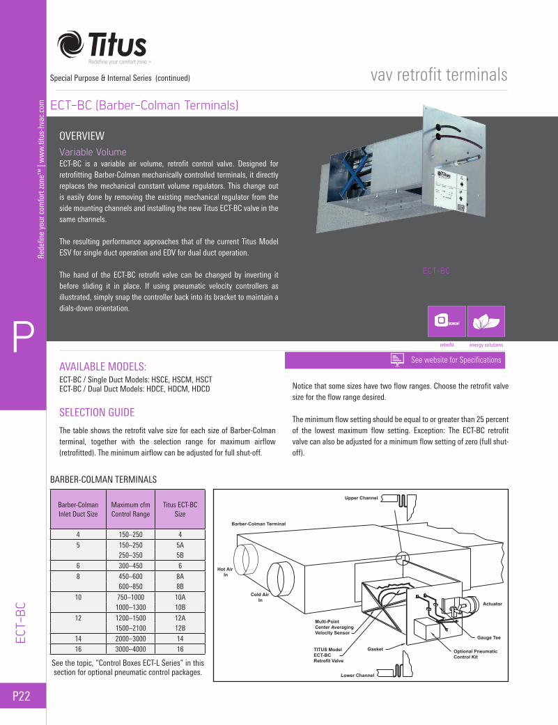
The table shows the retrofit valve size for each size of Barber-Colman terminal, together with the selection range for maximum airflow (retrofitted). The minimum airflow can be adjusted for full shut-off.
Notice that some sizes have two flow ranges. Choose the retrofit valve size for the flow range desired.
The minimum flow setting should be equal to or greater than 25 percent of the lowest maximum flow setting. Exception: The ECT-BC retrofit valve can also be adjusted for a minimum flow setting of zero (full shut-off).
ECT-BC (Barber-Colman Terminals)
OVERVIEWVariable VolumeECT-BC is a variable air volume, retrofit control valve. Designed for retrofitting Barber-Colman mechanically controlled terminals, it directly replaces the mechanical constant volume regulators. This change out is easily done by removing the existing mechanical regulator from the side mounting channels and installing the new Titus ECT-BC valve in the same channels.
The resulting performance approaches that of the current Titus Model ESV for single duct operation and EDV for dual duct operation.
The hand of the ECT-BC retrofit valve can be changed by inverting it before sliding it in place. If using pneumatic velocity controllers as illustrated, simply snap the controller back into its bracket to maintain a dials-down orientation.
energy solutionsretrofit
ECT-BC
Barber-ColmanInlet Duct Size
Maximum cfmControl Range
Titus ECT-BCSize
4 150–250 45 150–250 5A
250–350 5B6 300–450 68 450–600 8A
600–850 8B
10 750–1000 10A1000–1300 10B
12 1200–1500 12A1500–2100 12B
14 2000–3000 1416 3000–4000 16
See the topic, “Control Boxes ECT-L Series” in this section for optional pneumatic control packages.
Barber-Colman Terminal
Upper Channel
Multi-PointCenter AveragingVelocity Sensor
TITUS ModelECT-BCRetrofit Valve
Lower Channel
Actuator
Gauge Tee
Optional PneumaticControl Kit
Gasket
Hot Air In
Cold Air In
See website for Specifications
P
P23
Redefine your comfort zone™
| ww
w.titus-hvac.com
vav retrofit terminals
Design Single DuctSingle Duct with
ReheatDual Duct
Buensod Titus TitusRegulatory ECT-BU RetrofitQuantity Quantity cfmand Size and Size Range
4HS(R) 4–H 1–2 1-A 45–2005HS(R) 5–H 1–4 1-B 65–350
14 6HS(R) 6–H 1–4 1-C 85–450and 7HS(R) 7–H 1–6 1-D 115–65016 8HS(R) 8–H 1–10 1-E 150–800
9HS(R) 9–H 1–10 1-E 150–80010HS(R) 10–H 1–12 1-F 245–1350
142010 HLA 2–10 2-E 300–16002010 HLB 3–10 3-E 450–24002212 HLC 4–10 4-E 600–3200
16
1413A HLAS(R) HLA 2–10 2-E 300–16001413B HLBS(R) HLB 2–12 2-F 500–27001615A HLCS(R) HLC 3–10 3-E 450–24001615B HLDS(R) HLD 3–12 3-F 750–4000
Special Purpose & Internal Series (continued)
ECT-BU
BUENSOD TERMINALS
AVAILABLE MODEL:ECT-BU / H-Series, Designs 14 and 16
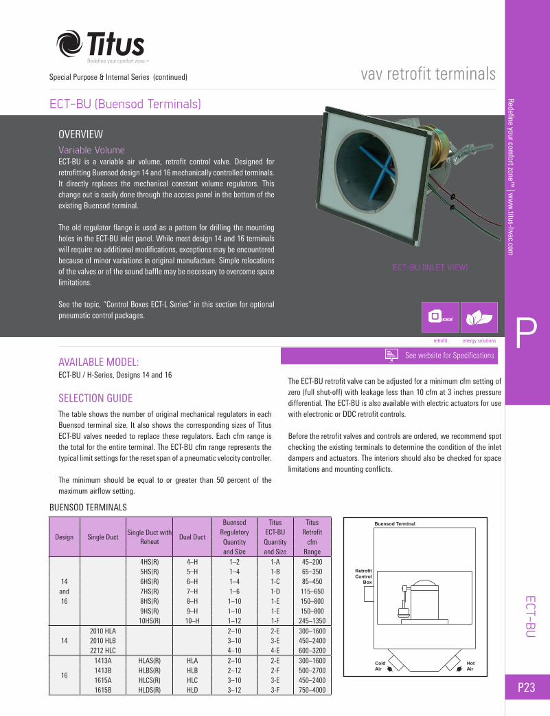
SELECTION GUIDEThe table shows the number of original mechanical regulators in each Buensod terminal size. It also shows the corresponding sizes of Titus ECT-BU valves needed to replace these regulators. Each cfm range is the total for the entire terminal. The ECT-BU cfm range represents the typical limit settings for the reset span of a pneumatic velocity controller.
The minimum should be equal to or greater than 50 percent of the maximum airflow setting.
The ECT-BU retrofit valve can be adjusted for a minimum cfm setting of zero (full shut-off) with leakage less than 10 cfm at 3 inches pressure differential. The ECT-BU is also available with electric actuators for use with electronic or DDC retrofit controls.
Before the retrofit valves and controls are ordered, we recommend spot checking the existing terminals to determine the condition of the inlet dampers and actuators. The interiors should also be checked for space limitations and mounting conflicts.
ECT-BU (Buensod Terminals)
OVERVIEWVariable VolumeECT-BU is a variable air volume, retrofit control valve. Designed for retrofitting Buensod design 14 and 16 mechanically controlled terminals. It directly replaces the mechanical constant volume regulators. This change out is easily done through the access panel in the bottom of the existing Buensod terminal.
The old regulator flange is used as a pattern for drilling the mounting holes in the ECT-BU inlet panel. While most design 14 and 16 terminals will require no additional modifications, exceptions may be encountered because of minor variations in original manufacture. Simple relocations of the valves or of the sound baffle may be necessary to overcome space limitations.
See the topic, “Control Boxes ECT-L Series” in this section for optional pneumatic control packages.
energy solutionsretrofit
ECT-BU (INLET VIEW)
See website for Specifications
Buensod Terminal
ColdAir
HotAir
RetrofitControl
Box

P24
P
Rede
fine
your
com
fort
zone
™ |
ww
w.ti
tus-
hvac
.com
vav retrofit terminals
Inlet
Dual Duct
Titus ECT-CN Size
Titus
Models: RetrofitDDC, DDV cfm
DSC Range
4 100-200 4 75-2005 175-325 5 100-3256 250-125 6 135-4257 400-650 7 225-6508 500-850 8 275-85010 650-1200 10 360-120012 1050-2000 12 700-200014 1500-3000 14 850-300016 2200-4000 16 1200-4000
Special Purpose & Internal Series (continued)
ECT-
CN
CONNOR TERMINALS
AVAILABLE MODEL:ECT-CN / 45 Series Dual Duct Models: DDC, DDV, DSC
SELECTION GUIDEThe table shows the original Connor terminal size, and corresponding sizes of Titus ECT-CN valves needed.
Each cfm range is the total for the entire terminal. The ECT-CN cfm range represents the typical limit settings for the reset span of a pneumatic velocity controller. The minimum should be equal to or greater than 50 percent of the maximum airflow setting.
The ECT-CN retrofit valve can also be adjusted for a minimum cfm setting of zero (full shut-off) with leakage less than 20 cfm at 3 inches pressure differential. The ECT-CN is also available with electric actuators for use with electronic or DDC retrofit controls.
Before the retrofit valves and controls are ordered, we recommend spot checking the existing terminals to determine the condition of the inlet dampers and actuators. The interiors should also be checked for space limitations and mounting conflicts.
ECT-CN (Connor Terminals)
OVERVIEWVariable VolumeECT-CN is a variable air volume, retrofit control valve. Designed for retrofitting Connor mechanically controlled terminals, it directly replaces the mechanical constant volume regulators. This change out is easily done through the access panel in the bottom of the existing Connor terminal.
The Titus ECT-CN valve fits the same space as the original constant volume regulator(s). The mounting holes in the ECT-CN inlet panel are pre-punched to fit the existing mounting bolts on sizes 4 to 10. On unit sizes 12 to 16, mounting holes must be drilled to match original bolt locations on the Connor regulator panel. Only a single ECT-CN is required to replace as many as four of the original mechanical regulators.
While most Connor terminals will require no additional modifications, exceptions may be encountered because of minor variations in original manufacture.
energy solutionsretrofit
ECT-CN
See the topic, “Control Boxes ECT-L Series” in this section for optional pneumatic control packages.
Connors Dual Duct Terminal
ColdAir
HotAir
See website for Specifications

P
P25
Redefine your comfort zone™
| ww
w.titus-hvac.com
vav retrofit terminals
DesignSingle Duct
Single Duct with Reheat
Dual Duct
Size cfm RangeNo. of Titus Regulators
No. of Titus ECT-HC Valves
1 Shipment 1968 through
1973TSH TSHR TDH
4 75-250 1 *5 115-350 1 *6 115-450 2 *7 230-650 2 18 250-850 3 19 250-1050 3 2
10 375-1350 4 212 500-2000 5 314 625-2700 7 416 750-4000 9 5
2 Shipments 1974 through
1984HS HSR HD
A 125-400 1 *B 250-800 2 1C 250-1200 3 2D 375-1600 4 2E 500-2300 5 3F 750-3200 7 4G 875-4100 9 5H 1200-5100 11 7J 1400-6000 13 8
Special Purpose & Internal Series (continued)
ECT-HC
TITUS TERMINALS
AVAILABLE MODEL:ECT-HC / Models: TDH, TDL, TSH, TSHR, HD, LD, HS, and HSR
SELECTION GUIDEThe table shows the maximum number of original constant volume regulators in each terminal model and size. It also shows the number of Model ECT-HC retrofit valves required to replace these regulators.
Each ECT-HC high capacity valve can control up to 800 cfm. Pneumatic
or electric actuators are available. Each cfm range is a total for the entire terminal. It represents typical limit settings for the reset span of the pressure independent pneumatic controller.
The ECT-HC valve can also be adjusted for a minimum cfm setting of zero (full shut-off) with leakage of less than 2 percent.
ECT-HC (Titus Terminals)
OVERVIEWVariable VolumeThe ECT-HC is a variable air volume, retrofit control valve. Designed for Titus mechanically controlled terminal units, it directly replaces the mechanical constant volume regulators in those models. This change out is easily done through the access panel in the bottom of the existing Titus terminal.
The resulting performance approaches that of the current Titus Model ESV and EDV terminals.
Some installations require fewer ECT-HC valves than the number of existing mechanical regulators. In those cases the extra regulators are removed and the openings are covered with metal plates.
The pneumatic actuators of as many as three ECT-HCs can be controlled by one Titus II controller. Any number of controllers can be signaled by one thermostat.
energy solutionsretrofit
ECT-HC
Contact factory for availability
See the topic, “Control Boxes ECT-L Series” in this section for optional pneumatic control packages.
Model TDH
See website for Specifications
Optional (ECT-L Series) Pneumatic Control Kit
Titus Dual Duct Mechanically Regulated Terminal

P26
P
Rede
fine
your
com
fort
zone
™ |
ww
w.ti
tus-
hvac
.com
vav retrofit terminals
Krueger Original Retrofitted Number of Number of ECT-KRTerminal cfm cfm Original ECT-KR Retrofit Valve
Size Range Range Regulators Valves Size4 100-200 45-200 1 1 N/A5 175-300 65-350 1 1 N/A6 300-450 85-450 1 1 C7 400-600 115-650 1 1 D8 500-800 150-850 1 1 E9 700-1000 300-1000 2 2 E10 800-1200 245-1300 1 1 F12 1000-1600 300-1600 2 2 E
12 x 12 1500-2500 460-2500 4 4 D16 x 14 1800-3000 600-3000 2 2 G20 x 14 2400-3900 600-3600 2 2 G
Special Purpose & Internal Series (continued)
ECT-
KR
KRUEGER TERMINALS
AVAILABLE MODEL:ECT-KR / Single Duct Models: CVM-ES, CVM-MS, CVM-RA, CVM-RBECT-KR / Dual Duct Models: CVM-ES, CVM-M, CVM-D
SELECTION GUIDEECT-KR is a variable air volume, retrofit control valve. Designed for retrofitting Krueger mechanically controlled terminals, it directly replaces the mechanical regulators in those models. This change out is easily done through the access panel in the bottom of the existing Kruger terminal.
Each cfm range is the total for the entire terminal. The ECT-KR cfm range represents the typical limit settings for the reset span of a pneumatic velocity controller.
The minimum should be equal to or greater than the 50 percent of the maximum airflow setting.
The ECT-KR retrofit valve can also be adjusted for a minimum cfm setting of zero (full shut-off) with leakage less than 10 cfm at 3 inches pressure differential. The ECT-KR is also available with electric actuators for use with electronic or DDC retrofit controls.
Before the retrofit valves and controls are ordered, we recommend spot checking the existing terminals to determine the condition of the inlet dampers and actuators. The interiors should also be checked for space limitations and mounting conflicts.
ECT-KR (Krueger Terminals)
OVERVIEWVariable VolumeECT-KR is a variable air volume, retrofit control valve. Designed for retrofitting Krueger mechanically controlled terminals, it directly replaces the mechanical regulators in those models. This change out is easily done through the access panel in the bottom of the existing Krueger terminal.
In some installations the new air volume is much less than the original, so that the terminals require fewer ECT-KR valves than the number of existing mechanical regulators. In those cases the extra regulators are removed and the openings are covered with metal plates.
energy solutionsretrofit
ECT-KR
See the topic, “Control Boxes ECT-L Series” in this section for optional pneumatic control packages.
Krueger Terminal
Cold Air Hot Air
Retrofit Control
Box
See website for Specifications
P
P27
Redefine your comfort zone™
| ww
w.titus-hvac.com
vav retrofit terminals
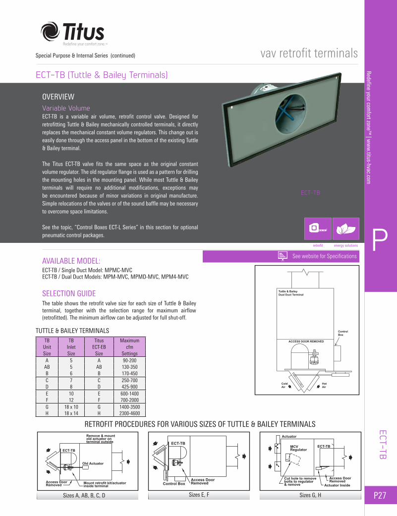
TB TB Titus MaximumUnit Inlet ECT-EB cfmSize Size Size Settings
A 5 A 90-200AB 5 AB 130-350B 6 B 170-450C 7 C 250-700D 8 D 425-900E 10 E 600-1400F 12 F 700-2000G 18 x 10 G 1400-3500H 18 x 14 H 2300-4600
RETROFIT PROCEDURES FOR VARIOUS SIZES OF TUTTLE & BAILEY TERMINALS
Special Purpose & Internal Series (continued)
ECT-TB
TUTTLE & BAILEY TERMINALS
AVAILABLE MODEL:ECT-TB / Single Duct Model: MPMC-MVCECT-TB / Dual Duct Models: MPM-MVC, MPMD-MVC, MPM4-MVC
SELECTION GUIDEThe table shows the retrofit valve size for each size of Tuttle & Bailey terminal, together with the selection range for maximum airflow (retrofitted). The minimum airflow can be adjusted for full shut-off.
ECT-TB (Tuttle & Bailey Terminals)
OVERVIEWVariable VolumeECT-TB is a variable air volume, retrofit control valve. Designed for retrofitting Tuttle & Bailey mechanically controlled terminals, it directly replaces the mechanical constant volume regulators. This change out is easily done through the access panel in the bottom of the existing Tuttle & Bailey terminal.
The Titus ECT-TB valve fits the same space as the original constant volume regulator. The old regulator flange is used as a pattern for drilling the mounting holes in the mounting panel. While most Tuttle & Bailey terminals will require no additional modifications, exceptions may be encountered because of minor variations in original manufacture. Simple relocations of the valves or of the sound baffle may be necessary to overcome space limitations.
See the topic, “Control Boxes ECT-L Series” in this section for optional pneumatic control packages.
energy solutionsretrofit
ECT-TB
See website for Specifications
Sizes G, H
Tuttle & Bailey Dual Duct Terminal
Control Box
Cold Air
TITUS Actuator
ACCESS DOOR REMOVED
TITUS Model ECT-TB Retrofit Valve
Multi-Point Inlet Sensor
Hot Air
Remove & mountold actuator on terminal outside
Mount retrofit kit/actuatorinside terminal
Access Door Removed
Old Actuator
ECT-TB
Access Door RemovedControl Box
ECT-TB
Access Door Removed
Actuator
Actuator Inside
Cut hole to removebolts to regulator& remove
MCVRegulator
ECT-TB
Sizes A, AB, B, C, D Sizes E, F

P28
P
Rede
fine
your
com
fort
zone
™ |
ww
w.ti
tus-
hvac
.com
vav retrofit terminals
CONTROL BOXES
Available Models: ECT-3LS ECT-3LD ECT-4LD
The pneumatic control connections in most installations are made as shown in the ECT-3LS diagram at the right. Just one Titus II pneumatic controller can control as many as four retrofit valves.
Although just one controller is shown in the diagram, any number of Titus II controllers can be connected in parallel to one room thermostat.
Note:
SCFM Standard Cubic Feet Per Minute
SCFH Standard Cubic Feet Per Hour
SCFM = SCFH/60
The ECT-3LD control box is used in both single duct and dual duct applications. Included are a high pressure selector switch and a reversing relay with its bias adjusted to match the start point of the water valve opening for single duct applications.
For dual duct applications, the reversing relay is normally adjusted to the mixing damper actuator start point pressure plus the actuator throttling pressure range, divided by two.
The ECT-4LD control box is typically used only in dual duct applications. In addition to the high pressure selector switch and reversing relay, a snap acting diverting relay is included.
The start point of the Titus II controller is normally set at 8 psi, and the switch point of the snap acting diverting relay is also set at 8 psi.
The diverting relay is also adjusted so that 8 psi in equals 8 psi out.
Note: Compressed air consumption values shown are for the Titus ECT-L control box only and do not include the thermostat.
ECT-L Series
Special Purpose & Internal Series (continued)
ECT-
L SE
RIES
ECT-3LSCompressed Air Consumption = 1.2 SCFH + Thermostat Loss
See the topic, ECT Series Applications in this section for Airflow Control SequenceTo Actuators
BoxControlECT-3LS
From Sensor
ValvesRetrofitTITUS
M
HITITUS II
B
LOT
Main Air20-25 psiM
T
Thermostat
ECT-3LDCompressed Air Consumption = 1.7 SCFH + Thermostat Loss
See the topic, ECT Series Applications in this section for Airflow Control Sequence
or Inlet ActuatorTo Existing Valve
To Actuators
From Sensor
ECT-3LDControlBox
TITUSRetrofitValves
HI
M
TITUS II
B
LO
ReversingRelay
T
SelectorHigh Pressure
20-25 psiMain Air
M
Thermostat
T
ECT-4LDCompressed Air Consumption = 1.7 SCFH + Thermostat Loss
See the topic, ECT Series Applications in this section for Airflow Control Sequence
To Existing Inlet Actuator
From SensorECT-3LS Snap
ActingDivertingRelay
S
CNCControl
Box
TITUS
To Actuators
RetrofitValves
HI
M
M
TITUS II
B
LO
ReversingRelay
T
SelectorHigh Pressure
20-25 psiMain AirM
Thermostat
T
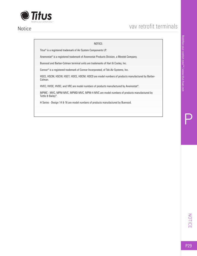
P
P29
Redefine your comfort zone™
| ww
w.titus-hvac.com
vav retrofit terminalsNotice
NOTICE:
Titus® is a registered trademark of Air System Components LP.
Anemostat® is a registered trademark of Anemostat Products Division, a Mestek Company.
Buensod and Barber-Colman terminal units are trademarks of Hart & Cooley, Inc.
Connor® is a registered trademark of Connor Incorporated, of Tek-Air Systems, Inc.
HSCE, HSCM, HSCW, HSCT, HDCE, HDCM, HDCD are model numbers of products manufactured by Barber-Colman.
HVEC, HVDC, HVOC, and VRC are model numbers of products manufactured by Anemostat®.
MPMC - MVC, MPM-MVC, MPMD-MVC, MPM-4-MVC are model numbers of products manufactured by Tuttle & Bailey®.
H Series - Design 14 & 16 are model numbers of products manufactured by Buensod.
NOTICE

Notes vav retrofit terminals


