

ce
i@u
pm
.es
Universidad Politécnica de Madrid
Virtual Prototyping and Optimization of EMC
Input FiltersNico Henri Hensgens
4th CEI Seminar - 25/03/2011Project funded by

25.03.2011 – 4th CEI Seminar2
Contents
Power Electronic Converters
EMI in Power Converters
EMI Input Filters
Virtual Prototyping of Input Filters
Multi-Objective Optimization of Input Filters
25.03.2011 – 4th CEI Seminar3
Power Electronic Converters
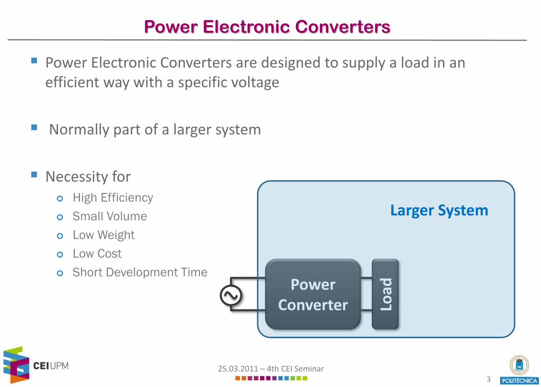
Power Electronic Converters are designed to supply a load in an efficient way with a specific voltage
Normally part of a larger system
Necessity for High Efficiency Small Volume Low Weight Low Cost Short Development Time
PowerConverter Lo
ad
Larger System
25.03.2011 – 4th CEI Seminar4
EMI in Power Converters
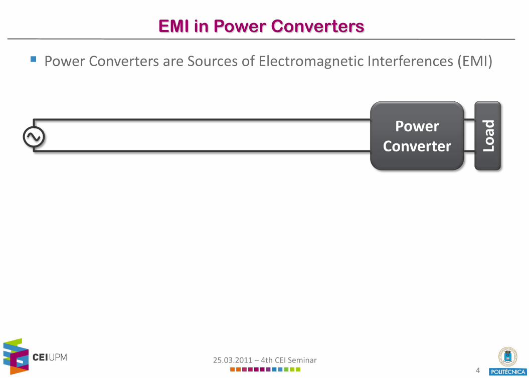
Power Converters are Sources of Electromagnetic Interferences (EMI)
PowerConverter Lo
ad

25.03.2011 – 4th CEI Seminar5
EMI in Power Converters
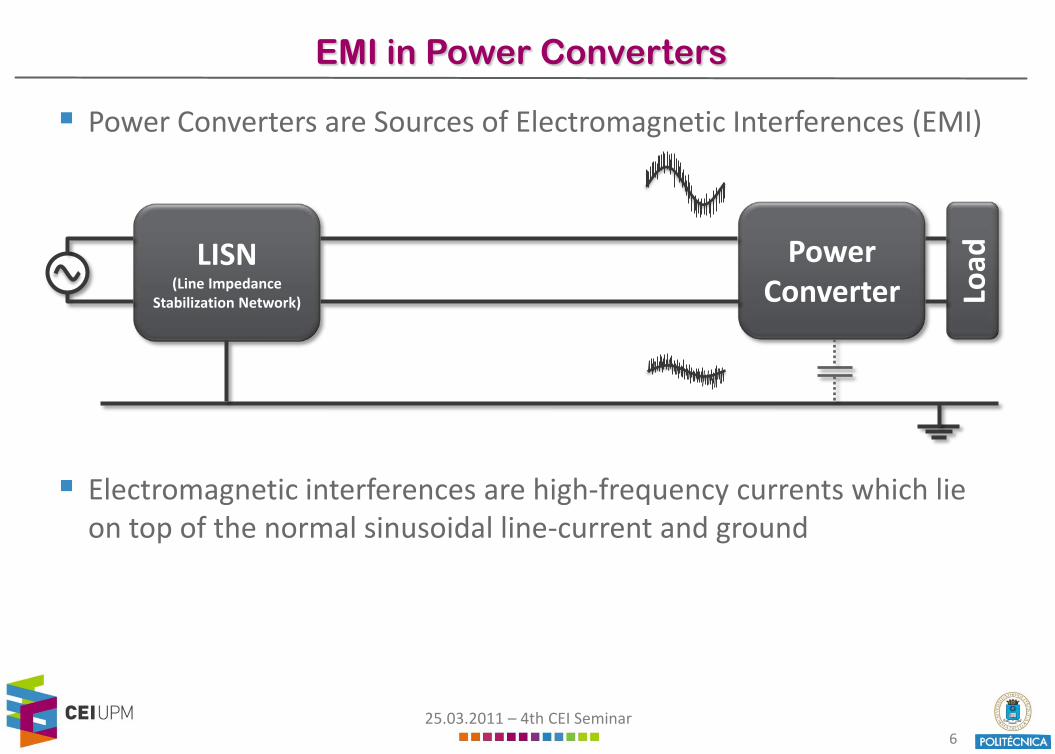
Power Converters are Sources of Electromagnetic Interferences (EMI)
Electromagnetic interferences are high-frequency currents which lie on top of the normal sinusoidal line-current and ground
PowerConverter Lo
ad
25.03.2011 – 4th CEI Seminar6
EMI in Power Converters
Power Converters are Sources of Electromagnetic Interferences (EMI)
Electromagnetic interferences are high-frequency currents which lie on top of the normal sinusoidal line-current and ground
PowerConverter
LISN(Line Impedance
Stabilization Network) Load

25.03.2011 – 4th CEI Seminar7
EMI in Power Converters
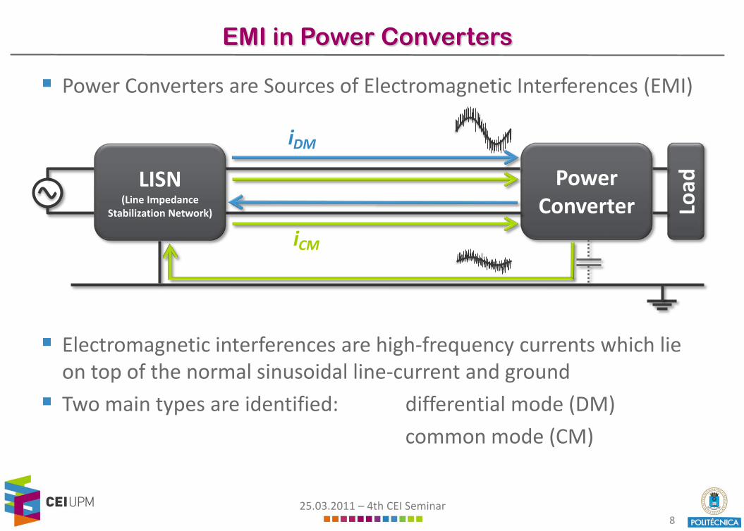
Power Converters are Sources of Electromagnetic Interferences (EMI)
Electromagnetic interferences are high-frequency currents which lie on top of the normal sinusoidal line-current and ground
Two main types are identified: differential mode (DM)
PowerConverter Lo
ad
iDM
LISN(Line Impedance
Stabilization Network)
25.03.2011 – 4th CEI Seminar8
EMI in Power Converters
Power Converters are Sources of Electromagnetic Interferences (EMI)
Electromagnetic interferences are high-frequency currents which lie on top of the normal sinusoidal line-current and ground
Two main types are identified: differential mode (DM)
common mode (CM)
PowerConverter Lo
ad
iDM
iCM
LISN(Line Impedance
Stabilization Network)

25.03.2011 – 4th CEI Seminar9
EMI in Power Converters
Power Converters are Sources of Electromagnetic Interferences (EMI)
EMI may interfere with other devices and disturb their normal operation
International standards have been established which limit themaximal levels of EMI power converters may produce
PowerConverter Lo
ad
iDM
iCM
LISN(Line Impedance
Stabilization Network)

25.03.2011 – 4th CEI Seminar10
EMI in Power Converters
Power Converters are Sources of Electromagnetic Interferences (EMI)
A filter needs to be placed between the power converter and themains to limit the EMI levels and to comply with the standards
PowerConverter Lo
adEMI FilterLISN(Line Impedance
Stabilization Network)
25.03.2011 – 4th CEI Seminar11
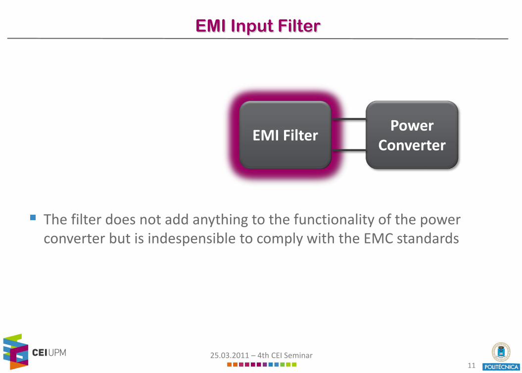
EMI Input Filter
The filter does not add anything to the functionality of the powerconverter but is indespensible to comply with the EMC standards
PowerConverter
EMI Filter
25.03.2011 – 4th CEI Seminar12
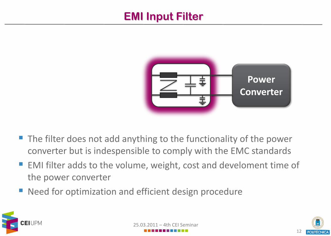
EMI Input Filter
The filter does not add anything to the functionality of the powerconverter but is indespensible to comply with the EMC standards
EMI filter adds to the volume, weight, cost and develoment time of the power converter
Need for optimization and efficient design procedure
PowerConverter
25.03.2011 – 4th CEI Seminar13
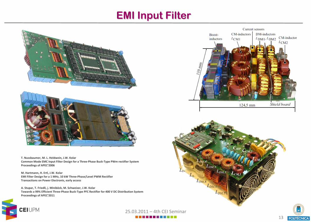
EMI Input Filter
T. Nussbaumer, M. L. Heldwein, J.W. KolarCommon Mode EMC Input Filter Design for a Three-Phase Buck-Type PWm rectifier SystemProceedings of APEC’2006
M. Hartmann, H. Ertl, J.W. KolarEMI Filter Design for a 1 MHz, 10 kW Three-Phase/Level PWM RectifierTransactions on Power Electronis, early access
A. Stupar, T. Friedli, j. Miniböck, M. Schweizer, J.W. KolarTowards a 99% Efficient Three-Phase Buck-Type PFC Rectifier for 400 V DC Distribution SystemProceedings of APEC’2011

25.03.2011 – 4th CEI Seminar14
EMI Input Filter
T. Nussbaumer, M. L. Heldwein, J.W. KolarCommon Mode EMC Input Filter Design for a Three-Phase Buck-Type PWm rectifier SystemProceedings of APEC’2006
M. Hartmann, H. Ertl, J.W. KolarEMI Filter Design for a 1 MHz, 10 kW Three-Phase/Level PWM RectifierTransactions on Power Electronis, early access
A. Stupar, T. Friedli, j. Miniböck, M. Schweizer, J.W. KolarTowards a 99% Efficient Three-Phase Buck-Type PFC Rectifier for 400 V DC Distribution SystemProceedings of APEC’2011

25.03.2011 – 4th CEI Seminar15
Input Filter Design
Classical Design Approach: Perform EMI measurements on existing prototype of the power converter Design EMI filter based on these measurements Calculation of filter components assuming ideal components and ignoring high-
frequency effects Several design iterations necessary until standards are met This approach results in long design times and suboptimal designs

25.03.2011 – 4th CEI Seminar16
Input Filter Design
Classical Design Approach: Perform EMI measurements on existing prototype of the power converter Design EMI filter based on these measurements Calculation of filter components assuming ideal components and ignoring high-
frequency effects Several design iterations necessary until standards are met This approach results in long design times and suboptimal designs
Filter design based on detailed analytical models and numerical simulations Start filter design at an earlier design stage
of converter system Reduce development time and time-to-market
25.03.2011 – 4th CEI Seminar17
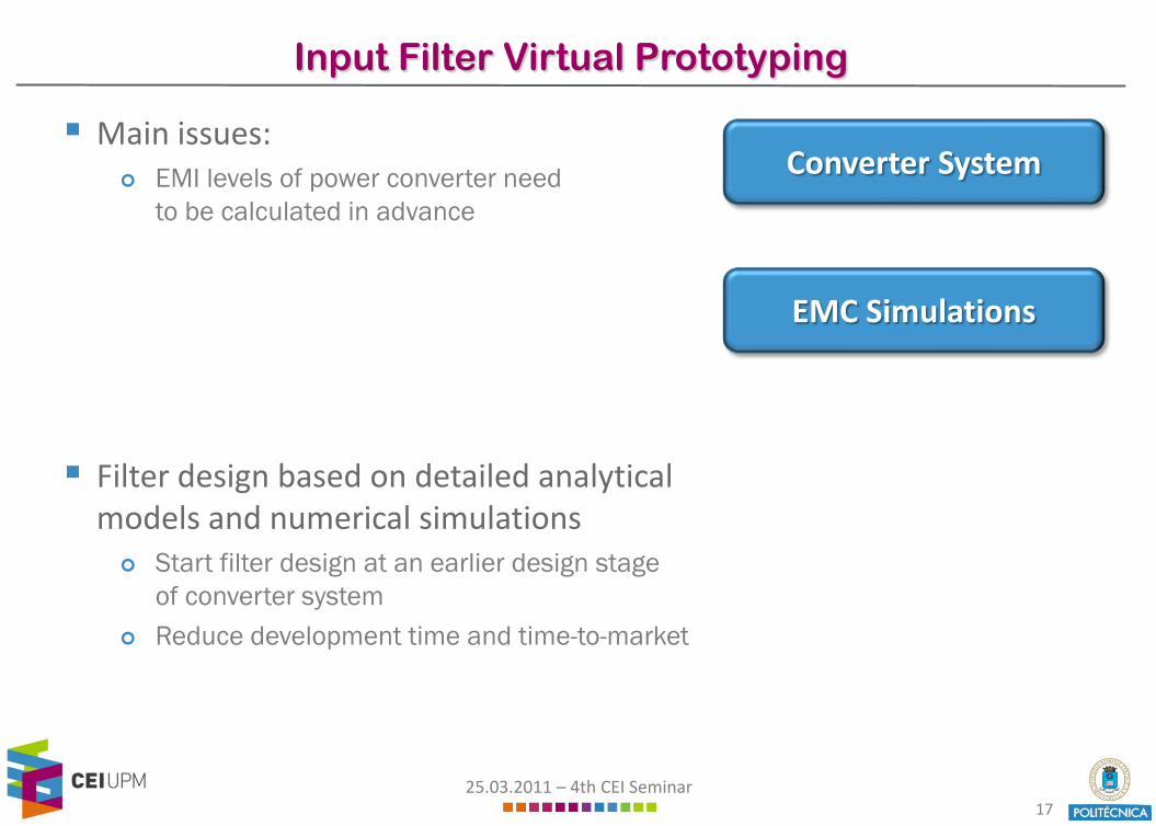
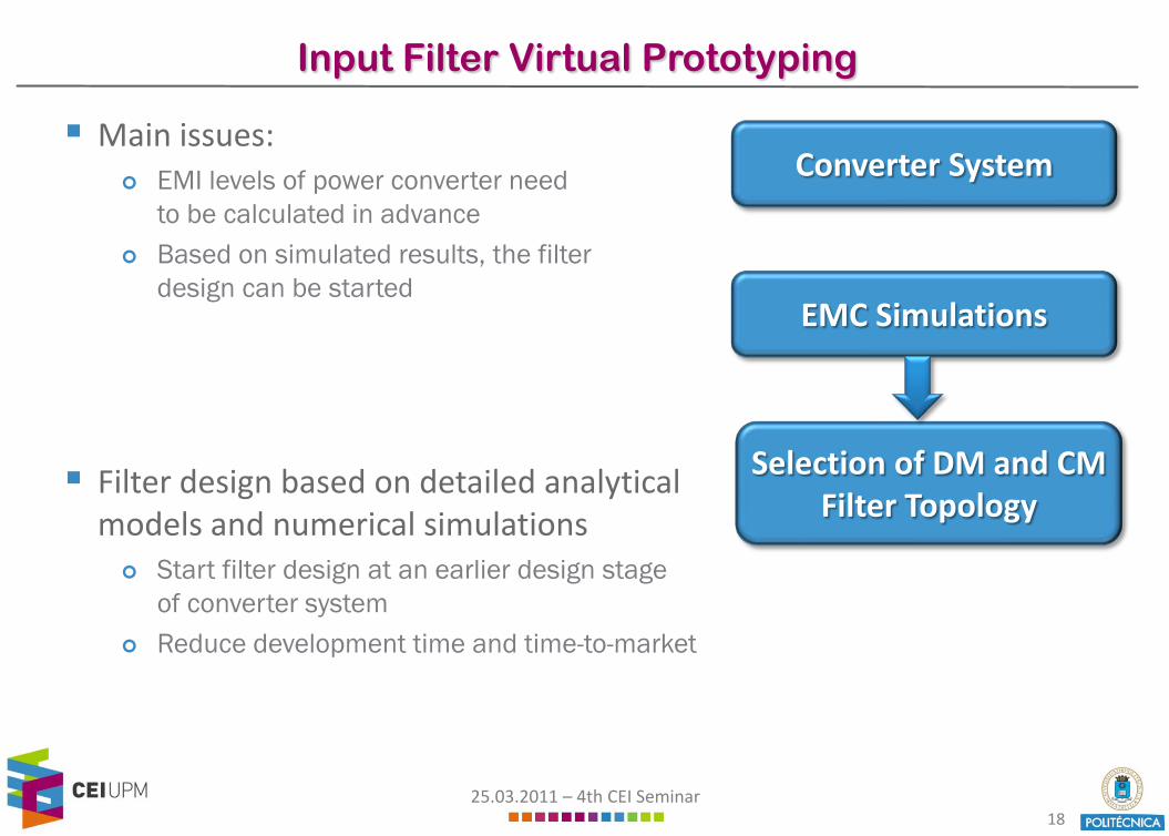
Input Filter Virtual Prototyping
Main issues: EMI levels of power converter need
to be calculated in advance
Filter design based on detailed analyticalmodels and numerical simulations Start filter design at an earlier design stage
of converter system Reduce development time and time-to-market
Converter System
EMC Simulations
25.03.2011 – 4th CEI Seminar18
Input Filter Virtual Prototyping
Main issues: EMI levels of power converter need
to be calculated in advance Based on simulated results, the filter
design can be started
Filter design based on detailed analyticalmodels and numerical simulations Start filter design at an earlier design stage
of converter system Reduce development time and time-to-market
Converter System
EMC Simulations
Selection of DM and CM Filter Topology
25.03.2011 – 4th CEI Seminar19
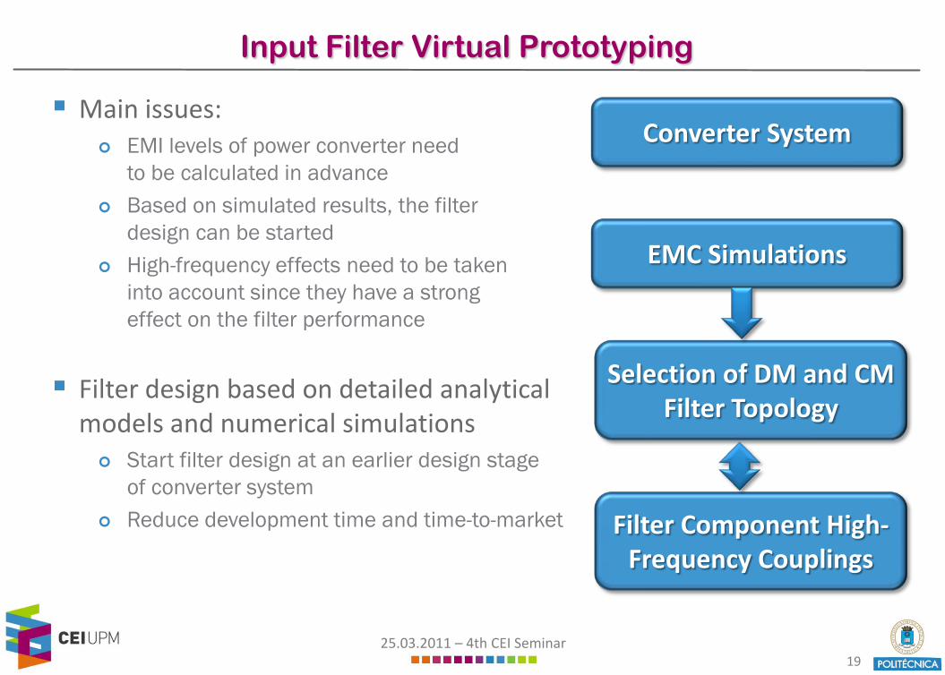
Input Filter Virtual Prototyping
Main issues: EMI levels of power converter need
to be calculated in advance Based on simulated results, the filter
design can be started High-frequency effects need to be taken
into account since they have a strongeffect on the filter performance
Filter design based on detailed analyticalmodels and numerical simulations Start filter design at an earlier design stage
of converter system Reduce development time and time-to-market
Converter System
EMC Simulations
Selection of DM and CM Filter Topology
Filter Component High-Frequency Couplings

25.03.2011 – 4th CEI Seminar20
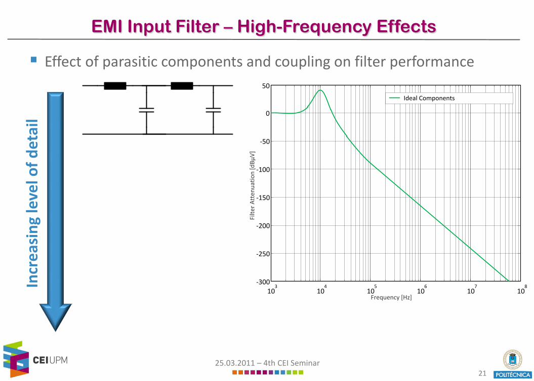
EMI Input Filter – High-Frequency Effects
Effect of parasitic components and coupling on filter performance
Frequency [Hz]
Filte
rAtt
enua
tion
[dBµ
V]
103
104
105
106
107
108
-300
-250
-200
-150
-100
-50
0
50
Incr
easi
ngle
velo
f det
ail
25.03.2011 – 4th CEI Seminar21
EMI Input Filter – High-Frequency Effects
Effect of parasitic components and coupling on filter performance
Incr
easi
ngle
velo
f det
ail
103
104
105
106
107
108
-300
-250
-200
-150
-100
-50
0
50
Ideal Components
Frequency [Hz]
Filte
rAtt
enua
tion
[dBµ
V]
25.03.2011 – 4th CEI Seminar22
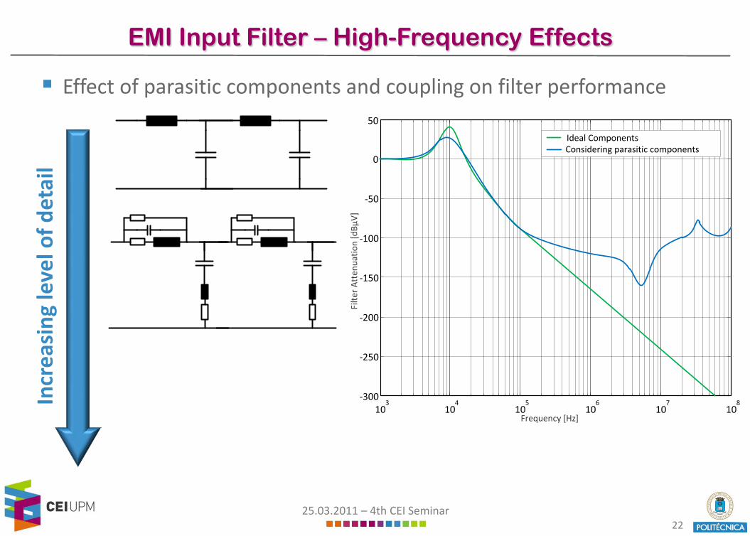
EMI Input Filter – High-Frequency Effects
Effect of parasitic components and coupling on filter performance
Incr
easi
ngle
velo
f det
ail
103
104
105
106
107
108
-300
-250
-200
-150
-100
-50
0
50
Ideal ComponentsConsidering parasitic components
Frequency [Hz]
Filte
rAtt
enua
tion
[dBµ
V]

25.03.2011 – 4th CEI Seminar23
EMI Input Filter – High-Frequency Effects
Effect of parasitic components and coupling on filter performance
Incr
easi
ngle
velo
f det
ail
Frequency [Hz]
Filte
rAtt
enua
tion
[dBµ
V]
103
104
105
106
107
108
-300
-250
-200
-150
-100
-50
0
50
Ideal ComponentsConsidering parasitic componentsConsidering parasitics and coupling
25.03.2011 – 4th CEI Seminar24
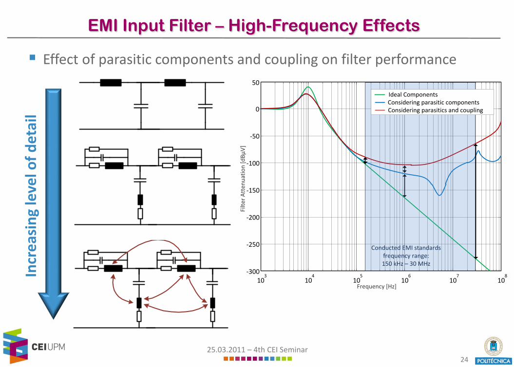
EMI Input Filter – High-Frequency Effects
Effect of parasitic components and coupling on filter performance
Incr
easi
ngle
velo
f det
ail
Frequency [Hz]
Filte
rAtt
enua
tion
[dBµ
V]
103
104
105
106
107
108
-300
-250
-200
-150
-100
-50
0
50
Ideal ComponentsConsidering parasitic componentsConsidering parasitics and coupling
Conducted EMI standardsfrequency range:150 kHz – 30 MHz
25.03.2011 – 4th CEI Seminar25
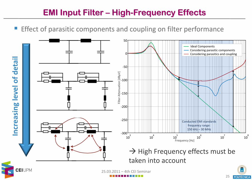
EMI Input Filter – High-Frequency Effects
Effect of parasitic components and coupling on filter performance
Incr
easi
ngle
velo
f det
ail
Frequency [Hz]
Filte
rAtt
enua
tion
[dBµ
V]
103
104
105
106
107
108
-300
-250
-200
-150
-100
-50
0
50
Ideal ComponentsConsidering parasitic componentsConsidering parasitics and coupling
Conducted EMI standardsfrequency range:150 kHz – 30 MHz
High Frequency effects must be taken into account
25.03.2011 – 4th CEI Seminar26
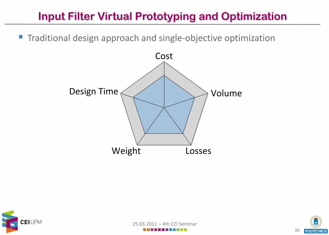
Input Filter Virtual Prototyping and Optimization
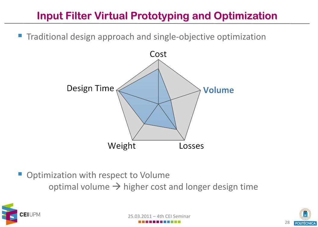
Traditional design approach and single-objective optimization
Cost
Design Time Volume
LossesWeight
25.03.2011 – 4th CEI Seminar27
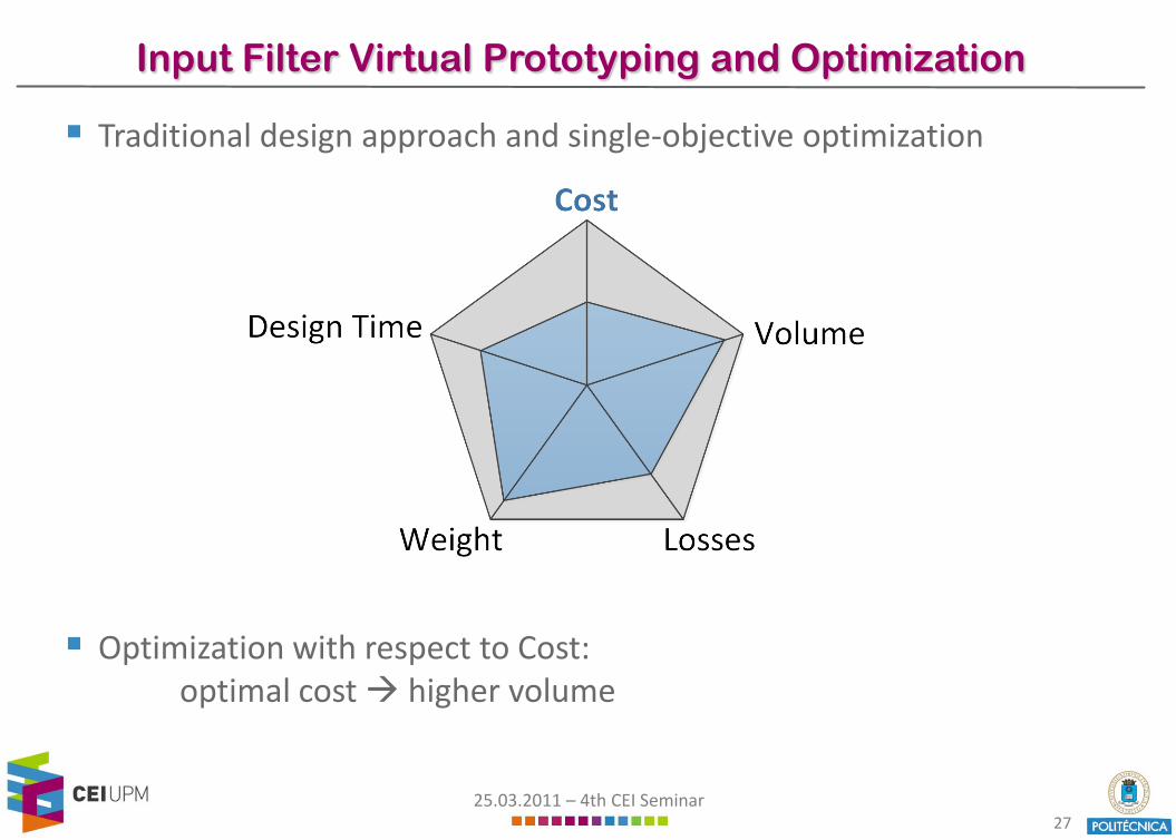
Input Filter Virtual Prototyping and Optimization
Traditional design approach and single-objective optimization
Optimization with respect to Cost:optimal cost higher volume
25.03.2011 – 4th CEI Seminar28
Input Filter Virtual Prototyping and Optimization
Traditional design approach and single-objective optimization
Optimization with respect to Volumeoptimal volume higher cost and longer design time
25.03.2011 – 4th CEI Seminar29
Input Filter Virtual Prototyping and Optimization
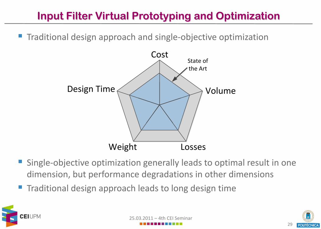
Traditional design approach and single-objective optimization
Single-objective optimization generally leads to optimal result in onedimension, but performance degradations in other dimensions
Traditional design approach leads to long design time
Cost
Design Time Volume
LossesWeight
State of the Art
25.03.2011 – 4th CEI Seminar30
Input Filter Virtual Prototyping and Optimization
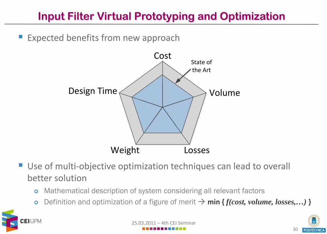
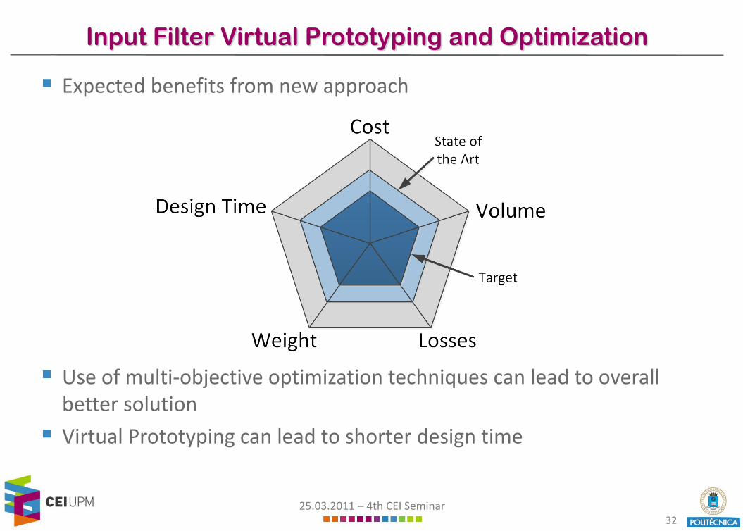
Expected benefits from new approach
Use of multi-objective optimization techniques can lead to overall better solution Mathematical description of system considering all relevant factors Definition and optimization of a figure of merit min { f(cost, volume, losses,…) }
Cost
Design Time Volume
LossesWeight
State of the Art
25.03.2011 – 4th CEI Seminar31
Input Filter Virtual Prototyping and Optimization
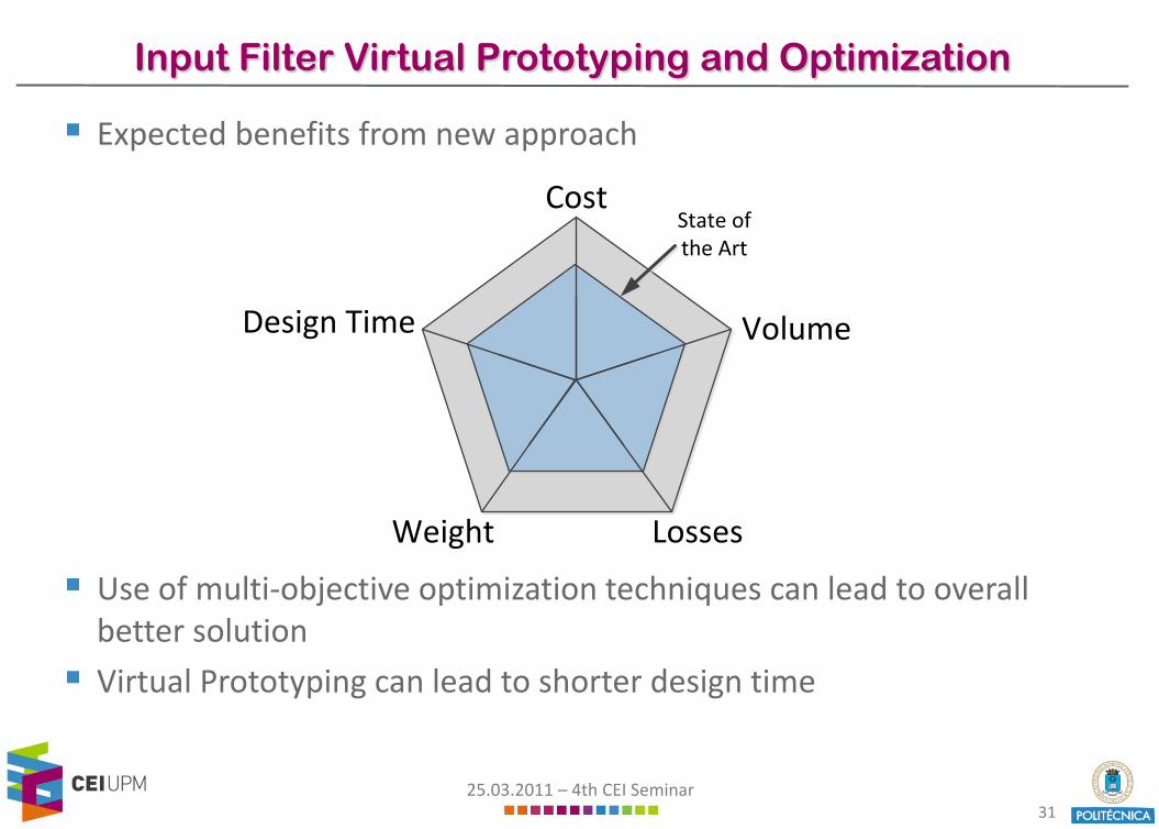
Expected benefits from new approach
Use of multi-objective optimization techniques can lead to overallbetter solution
Virtual Prototyping can lead to shorter design time
Cost
Design Time Volume
LossesWeight
State of the Art
25.03.2011 – 4th CEI Seminar32
Input Filter Virtual Prototyping and Optimization
Expected benefits from new approach
Use of multi-objective optimization techniques can lead to overallbetter solution
Virtual Prototyping can lead to shorter design time
25.03.2011 – 4th CEI Seminar33
Research Line - Summary
Power Converters are Sources of EMI
A Filter is mandatory to comply with international standards
The filter adds to the volume, weight, losses, cost and developmenttime of the converter system
Virtual Prototyping of the input filter can significantly reduce thedevelopment time and time-to-market of the converter system
Multi-objective optimization of the input filter can lead to a smaller, cheaper and more efficient solution

25.03.2011 – 4th CEI Seminar34
Project funded by


