
International Journal of Emerging Technology in Computer Science & Electronics (IJETCSE)
ISSN: 0976
Voltage Sag/Swell Compensation and Displacement Factor Improvement using IDVR in
Distribution NetworkVinothini.R1
PG Scholar, Power Electronics and Drives,Dr.Pauls Engineering College,
Villupuram, [email protected]
Abstract—In this Paper, an Interline Dynamic Voltage Restorer (IDVR) with Displacement Factor (DF) control is proposed for Voltage Sag/Swell Compeimprovement in Distribution Network. An Interline Dynamic Voltage Restorer (IDVR) is used to mitigate voltage sag/swell during abnormal condition in distribution system. It consists of several backVoltage Source Converters (VSC) with common During normal condition an IDVR is used to improve the Displacement Factor (DF) of one of DF improvement can be achieved by active and reacpower exchange (PQ sharing) between different feeders.Detailed simulation for the proposed IDVR system with DF improvement were carried MATLAB7/SIMULINK platform.
Index Terms—Voltage Sag/Swell Compensation, Harmonic Suppression, Displacement Improvement, Interline Dynamic(IDVR), PQ sharing mode.
I. INTRODUCT
In recent years, the most noticeable topic for Electrical Engineering is Power Quality(PQ)of the typical Power Quality (PQ) disturbances present in distribution system are voltage sags, voltage swells, interruptions, phase shifts, harmonics and transients. Among the disturbances voltage sag is considered as the most severe problem due to distribution network[2]. Several STATCOM, tap changing transformer, UPFC and DVR are existing to mitigate voltage sag problems. Among these, dynamic voltage restorer can most commercial solution to mitigate volinjecting voltage in addition to power into the system. Dynamic Voltage Restorer is a series connected power electronics based device that can quickly mitigate the voltage sag in the system and restore the load voltage to the pre-fault value. Consequentlyenergy storage within the DVR becomes one of the main restrictive factors in mitigating longvoltage sags. As a result, researchers presently pay greater attention to the DVR energy storage and its optimum use. The first DVR was
International Journal of Emerging Technology in Computer Science & Electronics (IJETCSE)
ISSN: 0976-1353 Volume 13 Issue 2 –MARCH 2015.
22
Voltage Sag/Swell Compensation and Displacement Factor Improvement using IDVR in
Distribution Network 1 Balamurugan.M
, Power Electronics and Drives, Associate Prof, Head of Dr.Pauls Engineering College, Dr.Pauls Engineering College,
Villupuram, India. Villupuram, [email protected] [email protected]
Interline Dynamic Voltage with Displacement Factor (DF) control
roposed for Voltage Sag/Swell Compensation and DF in Distribution Network. An Interline
Dynamic Voltage Restorer (IDVR) is used to mitigate voltage sag/swell during abnormal condition in
ystem. It consists of several back-to-back Voltage Source Converters (VSC) with common DC-link.
normal condition an IDVR is used to improve the the involved feeder.
DF improvement can be achieved by active and reactive sharing) between different feeders.
Detailed simulation for the proposed IDVR system with were carried out in
Voltage Sag/Swell Compensation, Harmonic Suppression, Displacement Factor
Dynamic Voltage Restorer
UCTION
In recent years, the most noticeable topic for Electrical Engineering is Power Quality(PQ)[1]. Some of the typical Power Quality (PQ) disturbances present in distribution system are voltage sags, voltage swells, interruptions, phase shifts, harmonics and transients. Among the disturbances voltage sag is considered as the most severe problem due to sensitive loads at
devices such as STATCOM, tap changing transformer, UPFC and
to mitigate voltage sag problems. Among these, dynamic voltage restorer can afford the most commercial solution to mitigate voltage sag by
power into the system. Dynamic Voltage Restorer is a series connected power electronics based device that can quickly mitigate the voltage sag in the system and restore the load voltage
onsequently, the amount of energy storage within the DVR becomes one of the
factors in mitigating long-duration , researchers presently pay
greater attention to the DVR energy storage and its s installed in North
America in 1996 - aAnderson, South Carolinaof injection voltage by voltage. In distribution systems, loadrestoration can be achireactive power into thepower capability of the Dof the energy storagecompensation technique
Several control for voltage sag compensation,phase, and minimal enerequired power for voltagethe neighbouring feeder(s),technically called anRestorer (IDVR)[16]. IDVR is derived fromController (IPFC) proposedexchange power betweenThe two converters of used to control the transmittedand P2) and active power transfer
Fig.1 Single line diagram
With respect tovoltage has two components.component provides reactthe line, while the ingenerates the requireddifference between an
International Journal of Emerging Technology in Computer Science & Electronics (IJETCSE) 2015.
Voltage Sag/Swell Compensation and Displacement Factor Improvement using IDVR in
Balamurugan.M2
Head of EEE Department, Engineering College,
Villupuram, India. [email protected]
a 12.47 kV system located in rolina[3]. Practically, the capability
DVR system is 50% of nominal ution systems, load voltage
achieved by injecting active and/or into the distribution feeder[5]. Active
DVR is governed by the capacity storage element and the employed
technique.
techniques have been proposed compensation, such as presag, in-
energy control approaches[6]. If the oltage restoration is obtained from
feeder(s), the compensating device is an Interline Dynamic Voltage . The basic concept behind the
from the Interline Power Flow proposed by Gyugyi in 1999 to
between parallel transmission lines. erters of the IPFC shown in Fig.1 are
the transmitted power in each line (P1 wer transfer between lines(P12).
diagram of an IPFC in transmission system
to the line current, the injected components. The quadrature
reactive power compensation for in-phase component absorbs or
required active power. The main IPFC, normal IDVR, and an
International Journal of Emerging Technology in Computer Science & Electronics (IJETCSE) ISSN: 0976-1353 Volume 13 Issue 2 –MARCH 2015.
23
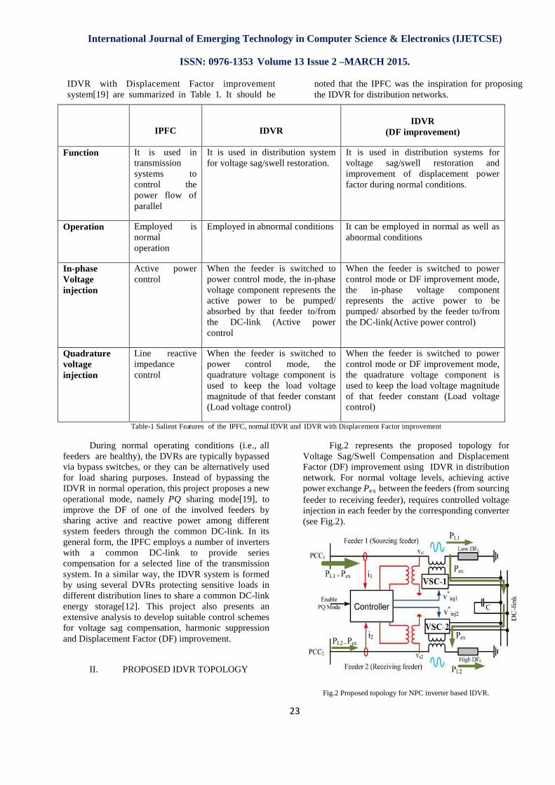
IDVR with Displacement Factor improvement system[19] are summarized in Table 1. It should be
noted that the IPFC was the inspiration for proposing the IDVR for distribution networks.
IPFC
IDVR
IDVR
(DF improvement)
Function It is used in transmission systems to control the power flow of parallel
It is used in distribution system for voltage sag/swell restoration.
It is used in distribution systems for voltage sag/swell restoration and improvement of displacement power factor during normal conditions.
Operation Employed is normal operation
Employed in abnormal conditions It can be employed in normal as well as abnormal conditions
In-phase Voltage injection
Active power control
When the feeder is switched to power control mode, the in-phase voltage component represents the active power to be pumped/ absorbed by that feeder to/from the DC-link (Active power control
When the feeder is switched to power control mode or DF improvement mode, the in-phase voltage component represents the active power to be pumped/ absorbed by the feeder to/from the DC-link(Active power control)
Quadrature voltage injection
Line reactive impedance control
When the feeder is switched to power control mode, the quadrature voltage component is used to keep the load voltage magnitude of that feeder constant (Load voltage control)
When the feeder is switched to power control mode or DF improvement mode, the quadrature voltage component is used to keep the load voltage magnitude of that feeder constant (Load voltage control)
Table-1 Salient Features of the IPFC, normal IDVR and IDVR with Displacement Factor improvement
During normal operating conditions (i.e., all feeders are healthy), the DVRs are typically bypassed via bypass switches, or they can be alternatively used for load sharing purposes. Instead of bypassing the IDVR in normal operation, this project proposes a new operational mode, namely PQ sharing mode[19], to improve the DF of one of the involved feeders by sharing active and reactive power among different system feeders through the common DC-link. In its general form, the IPFC employs a number of inverters with a common DC-link to provide series compensation for a selected line of the transmission system. In a similar way, the IDVR system is formed by using several DVRs protecting sensitive loads in different distribution lines to share a common DC-link energy storage[12]. This project also presents an extensive analysis to develop suitable control schemes for voltage sag compensation, harmonic suppression and Displacement Factor (DF) improvement.
II. PROPOSED IDVR TOPOLOGY
Fig.2 represents the proposed topology for Voltage Sag/Swell Compensation and Displacement Factor (DF) improvement using IDVR in distribution network. For normal voltage levels, achieving active power exchange Pex between the feeders (from sourcing feeder to receiving feeder), requires controlled voltage injection in each feeder by the corresponding converter (see Fig.2).
Fig.2 Proposed topology for NPC inverter based IDVR.
International Journal of Emerging Technology in Computer Science & Electronics (IJETCSE)
ISSN: 0976
This injected voltage should notvoltage magnitude of both feeders;converters are operating under PC mode.
A. Sourcing Feeder
The converter in the sourcingresponsible for feeding energy intoinjecting a controlled voltage (magnitudethrough the series coupled transformerpower exchange. In this paper, in ordereffect of voltage injection on theinjected voltage is emulated usingacross a series virtual impedance, asFig.3(a). The resistive componentimpedance absorbs active powersource, while the function of the capacitcomponent is to maintain a constantmagnitude. After voltage injection,active power increases while itsdecreases due to the virtual injectedreactance, hence, the sourcing feederincreases.
Fig.3 Sourcing feeder: (a) per-phase equivvirtual impedance injection and (b) phasor
Assuming a three-phase balanced
connected to the feeder; the percircuit of the feeder with series virtual impedinjection is shown in Fig.3(a),while correspondiphasor diagram shown in Fig.3(b).
The following section will sh
modes of operation are handled controller. A set of scenarios can be
International Journal of Emerging Technology in Computer Science & Electronics (IJETCSE)
ISSN: 0976-1353 Volume 13 Issue 2 –MARCH 2015.
24
not perturb the load feeders; therefore, both
mode.
sourcing feeder is into the dc link via
(magnitude and phase) transformer allowing for
order to emulate the the feeder DF, the
using a voltage drop impedance, as shown in
component of this virtual wer (Pex) from the
capacitive reactance constant load voltage
injection, the supply’s its reactive power injected capacitive
feeder DF eventually
ivalent circuit with
phasor diagram.
balanced load is r-phase equivalent
series virtual impedance (a),while corresponding
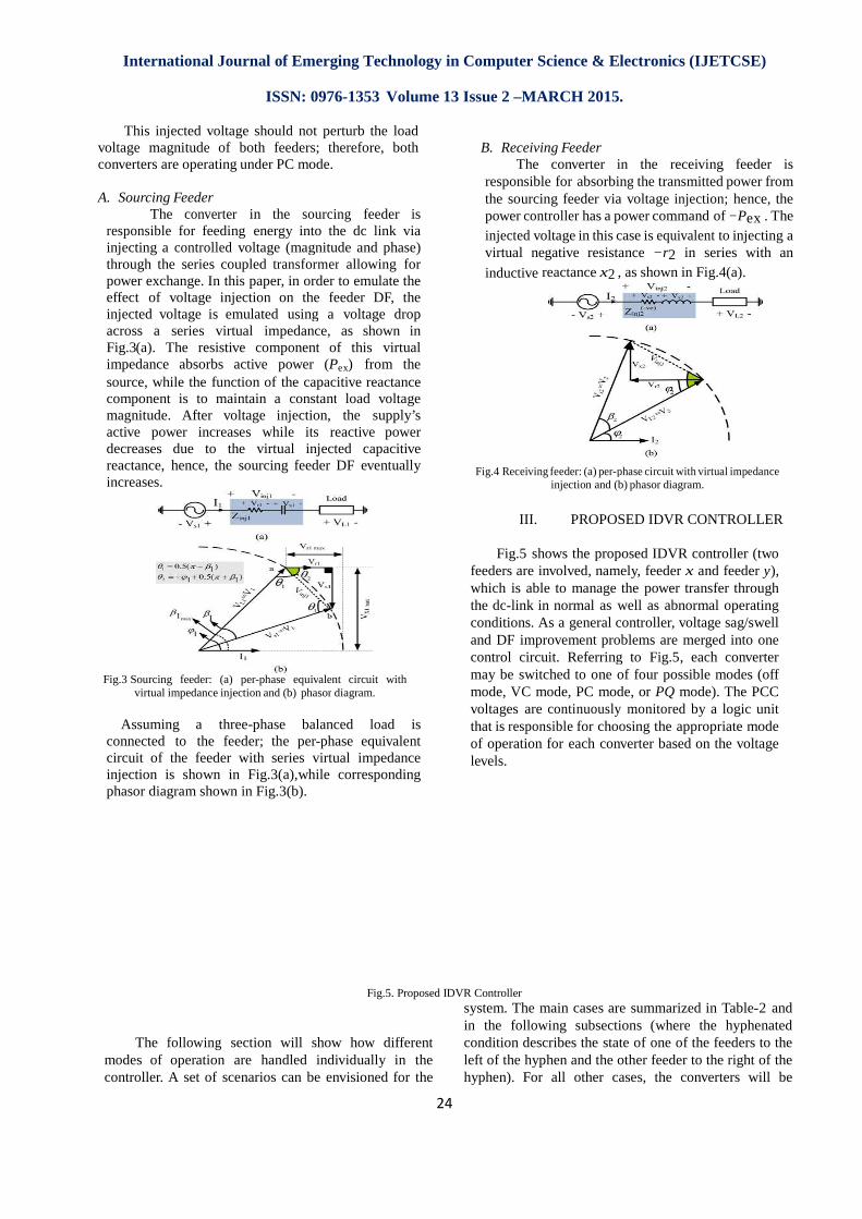
B. Receiving Feeder
The converter inresponsible for absorbingthe sourcing feeder via power controller has a poinjected voltage in this casevirtual negative resistance
inductive reactance x2 , as
Fig.4 Receiving feeder: (a) per-phaseinjection and (b)
III. PROPOSED IDVR CONTROLLER
Fig.5 shows the proposed IDVR controller (tfeeders are involved, namelwhich is able to manage thethe dc-link in normal as wellconditions. As a general controlleand DF improvement problemscontrol circuit. Referring tomay be switched to one ofmode, VC mode, PC mode,voltages are continuously that is responsible for choosing theof operation for each convlevels.
Fig.5. Proposed IDVR Controller
show how different individually in the be envisioned for the
system. The main cases arein the following subsections (wherecondition describes the stateleft of the hyphen and the other feeder tohyphen). For all other cases,
International Journal of Emerging Technology in Computer Science & Electronics (IJETCSE)
in the receiving feeder is absorbing the transmitted power from
voltage injection; hence, the ower command of −Pex . The
case is equivalent to injecting a resistance −r 2 in series with an
, as shown in Fig.4(a).
phase circuit with virtual impedance (b) phasor diagram.
PROPOSED IDVR CONTROLLER
proposed IDVR controller (two namely, feeder x and feeder y),
the power transfer through well as abnormal operating
general controller, voltage sag/swell ement problems are merged into one Referring to Fig.5, each converter
of four possible modes (off mode, or PQ mode). The PCC
monitored by a logic unit for choosing the appropriate mode
verter based on the voltage
cases are summarized in Table-2 and subsections (where the hyphenated
state of one of the feeders to the other feeder to the right of the
cases, the converters will be
International Journal of Emerging Technology in Computer Science & Electronics (IJETCSE)
ISSN: 0976
switched to the off position. Cases
CONVERTER - x
VC PC PQ Off
Vx is normal & sag at Vy 0 1 0 0 Vy is normal & sag ay Vx 1 0 0 0 Normal condition, PQ mode enabled
0 0 1 0
Normal condition, PQ modedisabled
0 0 0 1
Table-2. Proposed IDVR Controller CombinationsA. Normal–Normal (PQ Sharing
In this case, the logic unitpositions (see Fig.5) for both converters. B. Normal–Normal (PQ Sharing
In this case, the logic unitpositions (see Fig.5) for both convall constraints that accompany thisthe DFs of the loads connected tofeeders (DFLx and DFLy), the directionflow will be defined. The feederDF will be the sourcing feeder with apower reference, and the other receiving feeder with a negatreference. C. Normal–Voltage Sag
If one feeder exhibits voltagehas to switch its series converter toFig.5) to regulate the load voltage,power for restoration will be absorbed fromlink[22]. The converter of the healtswitched to its PC position (see
International Journal of Emerging Technology in Computer Science & Electronics (IJETCSE)
ISSN: 0976-1353 Volume 13 Issue 2 –MARCH 2015.
25
CONVERTER - y
VC PC PQ Off
1 0 0 0
0 1 0 0
0 0 1 0
0 0 0 1
2. Proposed IDVR Controller Combinations Mode is Disabled)
unit selects the OFF erters.
Mode is Enabled) unit selects the PQ verters after verifying this mode. Based on
connected to the involved direction of active power
feeder with a lower load feeder with a positive active
feeder will be the ative active power
oltage sag, the logic unit erter to VC position (see oltage, and the required
be absorbed from the dc healthy feeder will be
(see Fig.5) to replenish
the dc-link voltage[22]. Thethe dc link voltage will becontroller. This power corresponding converter reference
D. Normal–Voltage SwellIf one feeder
logic unit switches its position (see Fig.5) to Additional power is thenconverter of the healthy feederPC position (see Fig.5), tovoltage. The amount ofabsorbed by the healthy feedethe dc voltage controller.
IV. SIMULATION RESULTS
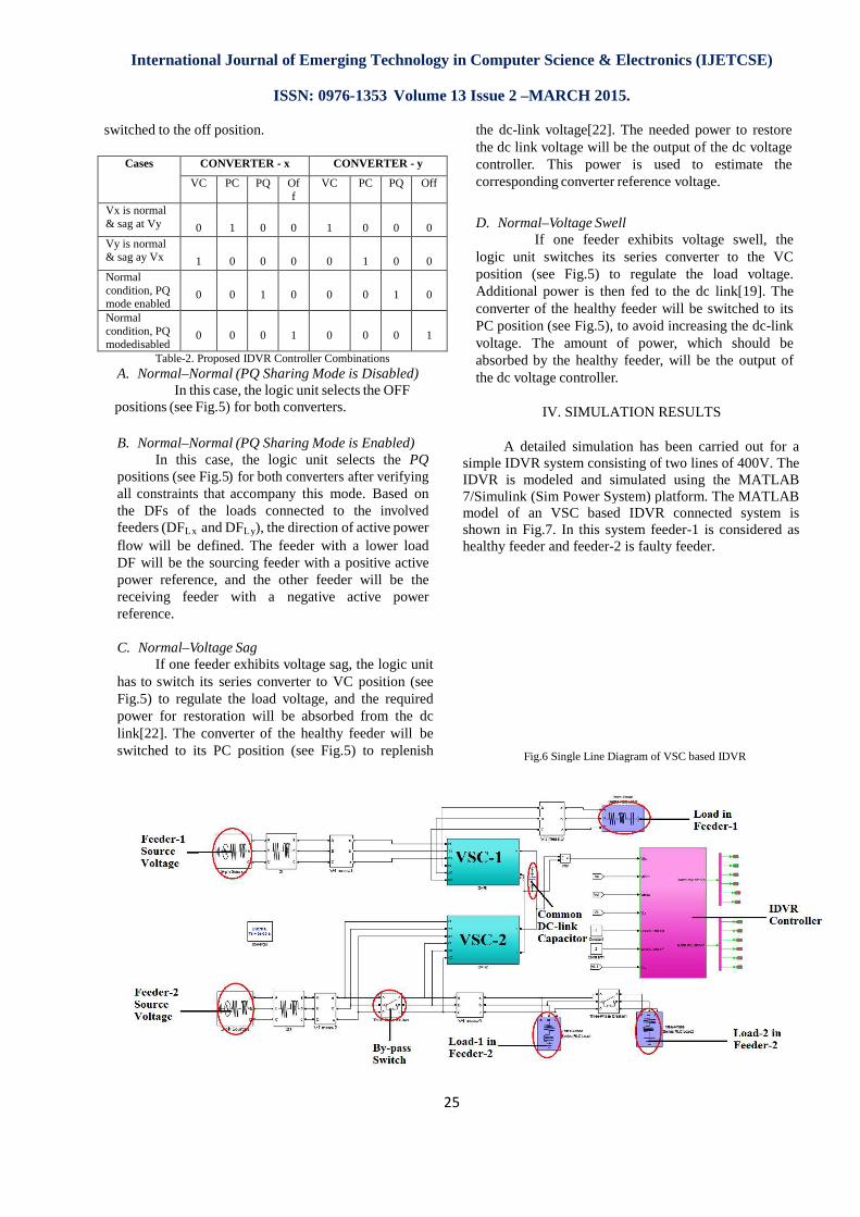
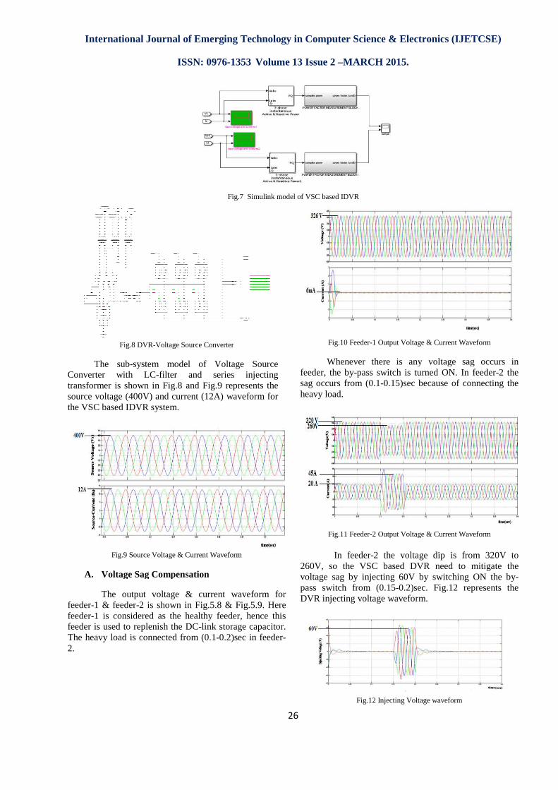
A detailed simulation has been carried out for a simple IDVR system consisting of two lines of 400V. The IDVR is modeled and simulated using the MATLAB 7/Simulink (Sim Power System) platform.model of an VSC based IDVR connshown in Fig.7. In this system feederhealthy feeder and feeder-2 is faulty feeder.
Fig.6 Single Line Diagram of VS
International Journal of Emerging Technology in Computer Science & Electronics (IJETCSE) 2015.
. The needed power to restore be the output of the dc voltage is used to estimate the reference voltage.
Swell exhibits voltage swell, the series converter to the VC regulate the load voltage.
then fed to the dc link[19]. The feeder will be switched to its to avoid increasing the dc-link of power, which should be
y feeder, will be the output of
IV. SIMULATION RESULTS
A detailed simulation has been carried out for a simple IDVR system consisting of two lines of 400V. The IDVR is modeled and simulated using the MATLAB
(Sim Power System) platform. The MATLAB model of an VSC based IDVR connected system is
. In this system feeder-1 is considered as 2 is faulty feeder.
Single Line Diagram of VSC based IDVR
International Journal of Emerging Technology in Computer Science & Electronics (IJETCSE)
ISSN: 0976
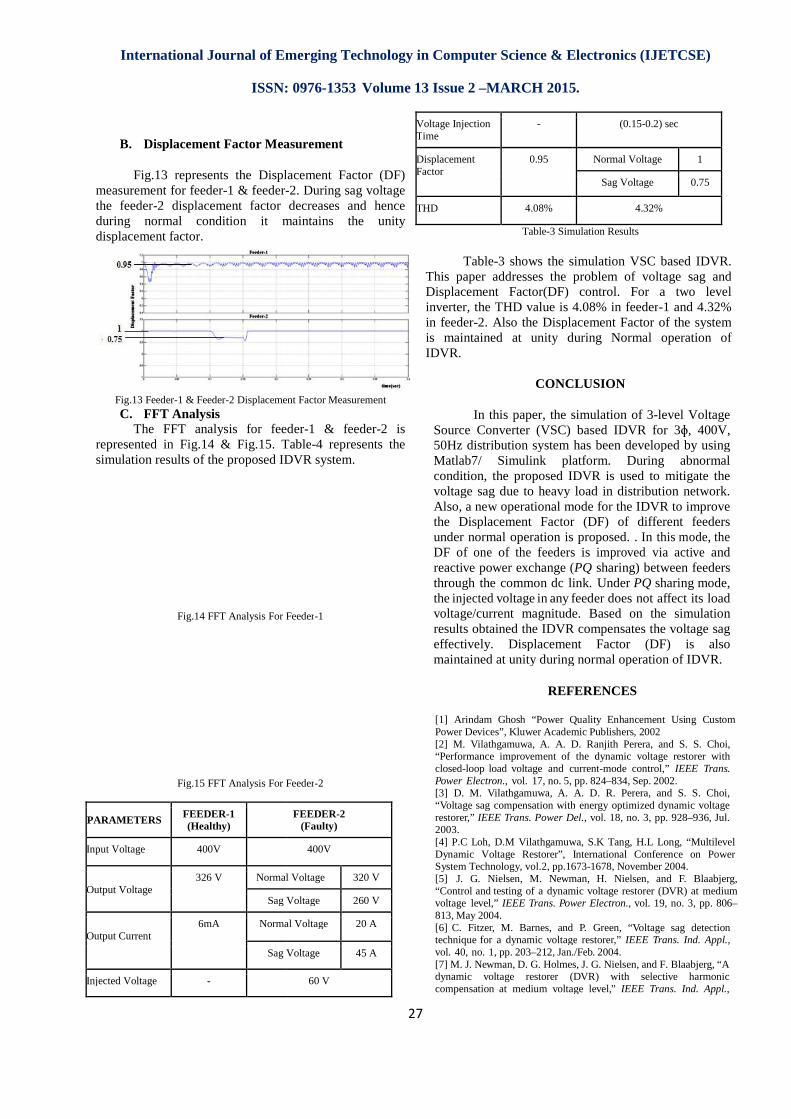
Fig.8 DVR-Voltage Source Converter
The sub-system model of Voltage Source Converter with LC-filter and seriestransformer is shown in Fig.8 and source voltage (400V) and current (12A) waveform for the VSC based IDVR system.
Fig.9 Source Voltage & Current Waveform
A. Voltage Sag Compensation
The output voltage & current waveform for feeder-1 & feeder-2 is shown in Fig.5.8 & Fig.5.9. Here feeder-1 is considered as the healthy feeder, hence this feeder is used to replenish the DC-link storage capacitor. The heavy load is connected from (0.12.
International Journal of Emerging Technology in Computer Science & Electronics (IJETCSE)
ISSN: 0976-1353 Volume 13 Issue 2 –MARCH 2015.
26
Fig.7 Simulink model of VSC based IDVR
Voltage Source Converter
system model of Voltage Source filter and series injecting
and Fig.9 represents the source voltage (400V) and current (12A) waveform for
Source Voltage & Current Waveform
Voltage Sag Compensation
The output voltage & current waveform for 2 is shown in Fig.5.8 & Fig.5.9. Here
1 is considered as the healthy feeder, hence this link storage capacitor.
The heavy load is connected from (0.1-0.2)sec in feeder-
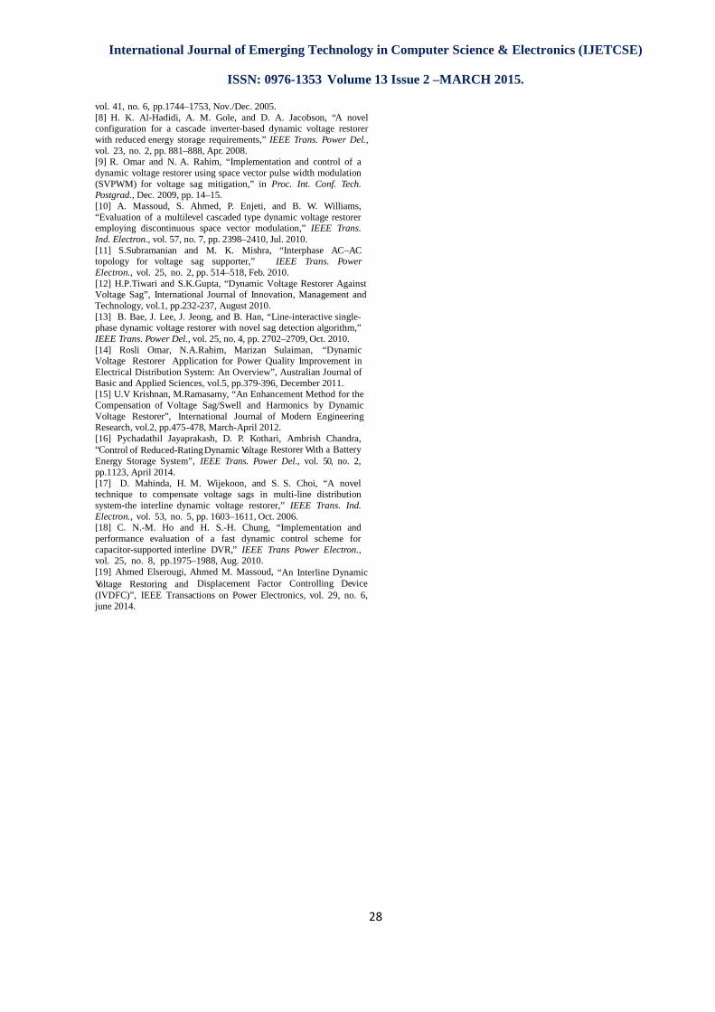
Fig.10 Feeder-1 Output Voltage & Current Waveform
Whenever there is any voltage sag occurs in feeder, the by-pass switch is turned ON. In feedersag occurs from (0.1-0.15)sec because of connecting the heavy load.
Fig.11 Feeder-2 Output Voltage &
In feeder-2 the voltage dip is from 320V to 260V, so the VSC based DVR need to mitigate the voltage sag by injecting 60V by switching ON the bypass switch from (0.15-0.2)sec. Fig.12DVR injecting voltage waveform.
Fig.12 Injecting Voltage waveform
International Journal of Emerging Technology in Computer Science & Electronics (IJETCSE) 2015.
1 Output Voltage & Current Waveform
Whenever there is any voltage sag occurs in pass switch is turned ON. In feeder-2 the
0.15)sec because of connecting the
2 Output Voltage & Current Waveform
2 the voltage dip is from 320V to 260V, so the VSC based DVR need to mitigate the voltage sag by injecting 60V by switching ON the by-
0.2)sec. Fig.12 represents the DVR injecting voltage waveform.
Injecting Voltage waveform
International Journal of Emerging Technology in Computer Science & Electronics (IJETCSE)
ISSN: 0976
B. Displacement Factor Measurement
Fig.13 represents the Displacement Factor (DF) measurement for feeder-1 & feeder-the feeder-2 displacement factor decreases and hence during normal condition it maintains displacement factor.
Fig.13 Feeder-1 & Feeder-2 Displacement Factor MeasurementC. FFT Analysis
The FFT analysis for feederrepresented in Fig.14 & Fig.15. Tablesimulation results of the proposed IDVR system.
Fig.14 FFT Analysis For Feeder
Fig.15 FFT Analysis For Feeder
PARAMETERS FEEDER-1 (Healthy)
Input Voltage 400V
Output Voltage
326 V Normal
Sag Voltage
Output Current
6mA Normal Voltage
Sag Voltage
Injected Voltage -
International Journal of Emerging Technology in Computer Science & Electronics (IJETCSE)
ISSN: 0976-1353 Volume 13 Issue 2 –MARCH 2015.
27
easurement
represents the Displacement Factor (DF) -2. During sag voltage
2 displacement factor decreases and hence during normal condition it maintains the unity
2 Displacement Factor Measurement
The FFT analysis for feeder-1 & feeder-2 is Table-4 represents the
simulation results of the proposed IDVR system.
FFT Analysis For Feeder-1
FFT Analysis For Feeder-2
FEEDER-2 (Faulty)
400V
Normal Voltage 320 V
Sag Voltage 260 V
Normal Voltage 20 A
Sag Voltage 45 A
60 V
Voltage Injection Time
-
Displacement Factor
0.95
THD 4.08%
Table-3 Simulation Results
Table-3 shows the simulatThis paper addresses the problem of Displacement Factor(DF) controlinverter, the THD value is 4.08% in feederin feeder-2. Also the Displacement Factor of the system is maintained at unity during NIDVR.
CONCLUSION
In this paper, the simulation of 3Source Converter (VSC) based IDVR for 350Hz distribution system has been developed by using Matlab7/ Simulink platform. During abnormal condition, the proposed IDVR is used to mitigate the voltage sag due to heavy load in distribution network. Also, a new operational mode for the IDVR to improve the Displacement Factor (DF) of different feeders under normal operation is proposed. DF of one of the feedersreactive power exchange (through the common dc link. Underthe injected voltage in any feeder doesvoltage/current magnitude.results obtained the IDVR compensates the voltage sag effectively. Displacement Factor (DF) is also maintained at unity during normal operation of IDVR.
REFERENCES
[1] Arindam Ghosh “Power QPower Devices”, Kluwer Academi[2] M. Vilathgamuwa, A. A. D.“Performance improvement of closed-loop load voltage and currentPower Electron., vol. 17, no. 5, [3] D. M. Vilathgamuwa, A. “Voltage sag compensation withrestorer,” IEEE Trans. Power D2003. [4] P.C Loh, D.M VilathgamuwDynamic Voltage Restorer”, System Technology, vol.2, pp.167[5] J. G. Nielsen, M. Newman,“Control and testing of a dynamicvoltage level,” IEEE Trans. Power813, May 2004. [6] C. Fitzer, M. Barnes, andtechnique for a dynamic voltagevol. 40, no. 1, pp. 203–212, Jan./Fe[7] M. J. Newman, D. G. Holmes,dynamic voltage restorer (compensation at medium voltage
International Journal of Emerging Technology in Computer Science & Electronics (IJETCSE) 2015.
(0.15-0.2) sec
Normal Voltage 1
Sag Voltage 0.75
4.32%
Simulation Results
simulation VSC based IDVR. This paper addresses the problem of voltage sag and Displacement Factor(DF) control. For a two level
the THD value is 4.08% in feeder-1 and 4.32% the Displacement Factor of the system
during Normal operation of
CONCLUSION
In this paper, the simulation of 3-level Voltage Source Converter (VSC) based IDVR for 3ɸ, 400V, 50Hz distribution system has been developed by using
platform. During abnormal condition, the proposed IDVR is used to mitigate the voltage sag due to heavy load in distribution network. Also, a new operational mode for the IDVR to improve the Displacement Factor (DF) of different feeders
tion is proposed. . In this mode, the feeders is improved via active and
(PQ sharing) between feeders link. Under PQ sharing mode, feeder does not affect its load
oltage/current magnitude. Based on the simulation results obtained the IDVR compensates the voltage sag effectively. Displacement Factor (DF) is also maintained at unity during normal operation of IDVR.
REFERENCES
Quality Enhancement Using Custom mic Publishers, 2002 D. Ranjith Perera, and S. S. Choi, the dynamic voltage restorer with current-mode control,” IEEE Trans. pp. 824–834, Sep. 2002.
A. D. R. Perera, and S. S. Choi, ith energy optimized dynamic voltage Del., vol. 18, no. 3, pp. 928–936, Jul.
wa, S.K Tang, H.L Long, “Multilevel International Conference on Power
.2, pp.1673-1678, November 2004. wman, H. Nielsen, and F. Blaabjerg,
dynamic voltage restorer (DVR) at medium ower Electron., vol. 19, no. 3, pp. 806–
and P. Green, “Voltage sag detection oltage restorer,” IEEE Trans. Ind. Appl., Jan./Feb. 2004.
Holmes, J. G. Nielsen, and F. Blaabjerg, “A (DVR) with selective harmonic
oltage level,” IEEE Trans. Ind. Appl.,
International Journal of Emerging Technology in Computer Science & Electronics (IJETCSE) ISSN: 0976-1353 Volume 13 Issue 2 –MARCH 2015.
28
vol. 41, no. 6, pp.1744–1753, Nov./Dec. 2005. [8] H. K. Al-Hadidi, A. M. Gole, and D. A. Jacobson, “A novel configuration for a cascade inverter-based dynamic voltage restorer with reduced energy storage requirements,” IEEE Trans. Power Del., vol. 23, no. 2, pp. 881–888, Apr. 2008. [9] R. Omar and N. A. Rahim, “Implementation and control of a dynamic voltage restorer using space vector pulse width modulation (SVPWM) for voltage sag mitigation,” in Proc. Int. Conf. Tech. Postgrad., Dec. 2009, pp. 14–15. [10] A. Massoud, S. Ahmed, P. Enjeti, and B. W. Williams, “Evaluation of a multilevel cascaded type dynamic voltage restorer employing discontinuous space vector modulation,” IEEE Trans. Ind. Electron., vol. 57, no. 7, pp. 2398–2410, Jul. 2010. [11] S.Subramanian and M. K. Mishra, “Interphase AC–AC topology for voltage sag supporter,” IEEE Trans. Power Electron., vol. 25, no. 2, pp. 514–518, Feb. 2010. [12] H.P.Tiwari and S.K.Gupta, “Dynamic Voltage Restorer Against Voltage Sag”, International Journal of Innovation, Management and Technology, vol.1, pp.232-237, August 2010. [13] B. Bae, J. Lee, J. Jeong, and B. Han, “Line-interactive single-phase dynamic voltage restorer with novel sag detection algorithm,” IEEE Trans. Power Del., vol. 25, no. 4, pp. 2702–2709, Oct. 2010. [14] Rosli Omar, N.A.Rahim, Marizan Sulaiman, “Dynamic Voltage Restorer Application for Power Quality Improvement in Electrical Distribution System: An Overview”, Australian Journal of Basic and Applied Sciences, vol.5, pp.379-396, December 2011. [15] U.V Krishnan, M.Ramasamy, “An Enhancement Method for the Compensation of Voltage Sag/Swell and Harmonics by Dynamic Voltage Restorer”, International Journal of Modern Engineering Research, vol.2, pp.475-478, March-April 2012. [16] Pychadathil Jayaprakash, D. P. Kothari, Ambrish Chandra, “Control of Reduced-Rating Dynamic Voltage Restorer With a Battery Energy Storage System”, IEEE Trans. Power Del., vol. 50, no. 2, pp.1123, April 2014. [17] D. Mahinda, H. M. Wijekoon, and S. S. Choi, “A novel technique to compensate voltage sags in multi-line distribution system-the interline dynamic voltage restorer,” IEEE Trans. Ind. Electron., vol. 53, no. 5, pp. 1603–1611, Oct. 2006. [18] C. N.-M. Ho and H. S.-H. Chung, “Implementation and performance evaluation of a fast dynamic control scheme for capacitor-supported interline DVR,” IEEE Trans Power Electron., vol. 25, no. 8, pp.1975–1988, Aug. 2010. [19] Ahmed Elserougi, Ahmed M. Massoud, “An Interline Dynamic Voltage Restoring and Displacement Factor Controlling Device (IVDFC)” , IEEE Transactions on Power Electronics, vol. 29, no. 6, june 2014.


