
08/06/2016
1
TOP SECRET
SECRET
INTERNAL USE ONLY
PUBLIC
Current Daikin VRV lineup
General information, features
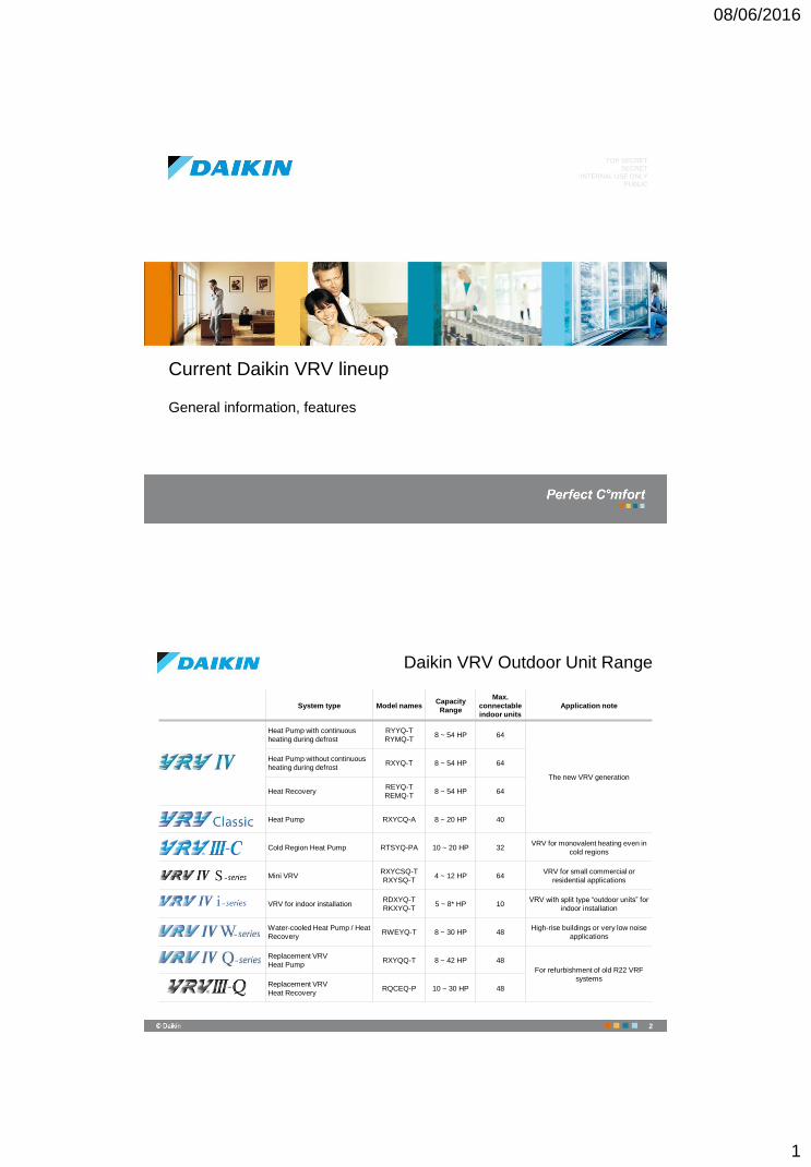
Daikin VRV Outdoor Unit Range
System type Model namesCapacity
Range
Max.
connectable
indoor units
Application note
Heat Pump with continuous
heating during defrost
RYYQ-T
RYMQ-T8 ~ 54 HP 64
The new VRV generation
Heat Pump without continuous
heating during defrostRXYQ-T 8 ~ 54 HP 64
Heat RecoveryREYQ-T
REMQ-T8 ~ 54 HP 64
Heat Pump RXYCQ-A 8 ~ 20 HP 40
Cold Region Heat Pump RTSYQ-PA 10 ~ 20 HP 32VRV for monovalent heating even in
cold regions
Mini VRV RXYCSQ-T
RXYSQ-T4 ~ 12 HP 64
VRV for small commercial or
residential applications
VRV for indoor installationRDXYQ-T
RKXYQ-T5 ~ 8* HP 10
VRV with split type “outdoor units” for
indoor installation
Water-cooled Heat Pump / Heat
RecoveryRWEYQ-T 8 ~ 30 HP 48
High-rise buildings or very low noise
applications
Replacement VRV
Heat PumpRXYQQ-T 8 ~ 42 HP 48
For refurbishment of old R22 VRF
systemsReplacement VRV
Heat RecoveryRQCEQ-P 10 ~ 30 HP 48
2
08/06/2016
2
Daikin VRV Outdoor Unit Range
The VRV IV Generation
3
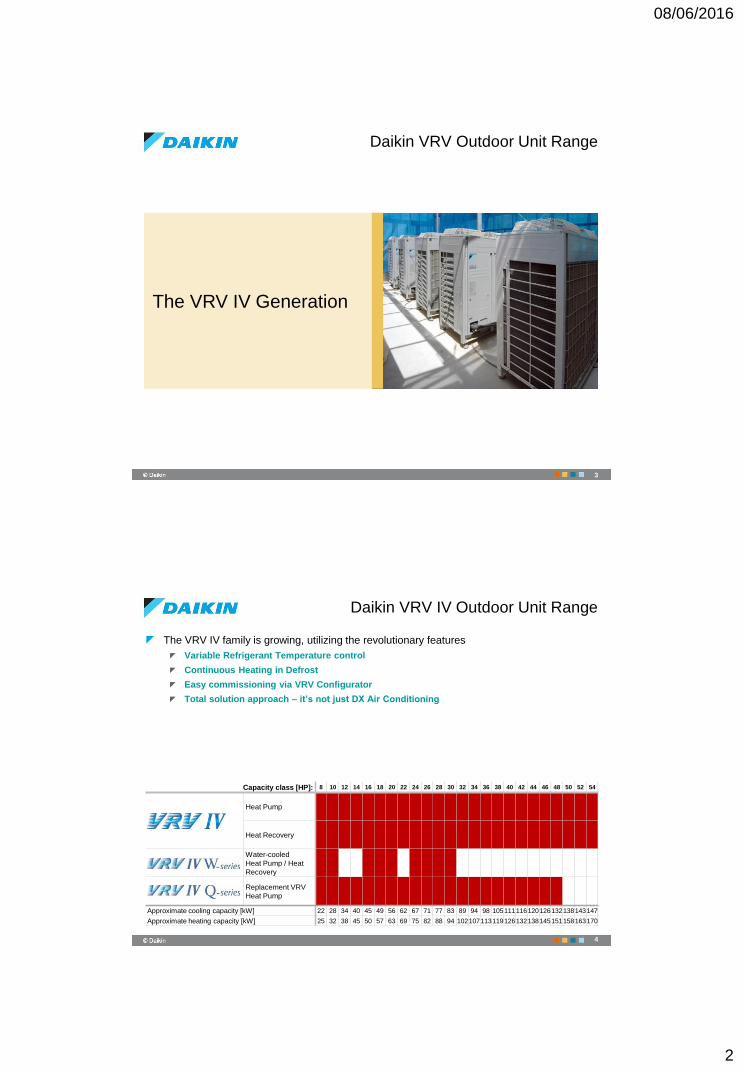
Daikin VRV IV Outdoor Unit Range
The VRV IV family is growing, utilizing the revolutionary features
Variable Refrigerant Temperature control
Continuous Heating in Defrost
Easy commissioning via VRV Configurator
Total solution approach – it’s not just DX Air Conditioning
4
Capacity class [HP]: 8 10 12 14 16 18 20 22 24 26 28 30 32 34 36 38 40 42 44 46 48 50 52 54
Heat Pump
Heat Recovery
Water-cooled
Heat Pump / Heat
Recovery
Replacement VRV
Heat Pump
Approximate cooling capacity [kW] 22 28 34 40 45 49 56 62 67 71 77 83 89 94 98 105111116120126132138143147
Approximate heating capacity [kW] 25 32 38 45 50 57 63 69 75 82 88 94 102107113119126132138145151158163170
08/06/2016
3
Variable Refrigerant
Temperature control
5
VRV IV Unique Features
Sys
tem
capacity
Refrig
era
nt T
35°25° 30°20°
Effic
iency
35°25° 30°20°
Outdoor temperature
Example: cooling
Fixed Tr
Capacity &
Load
35°25° 30°20°
Cooling
requirement
Design
point
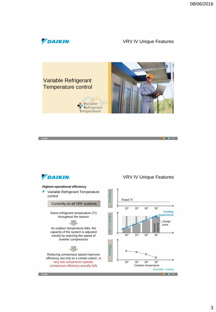
Currently on all VRF systems
Same refrigerant temperature (Tr)
throughout the season
As outdoor temperature falls, the
capacity of the system is adjusted
merely by reducing the speed of
inverter compressors
Reducing compressor speed improves
efficiency, but only to a certain extent: at
very low compressor speeds,
compressor efficiency actually falls
VRV IV Unique Features
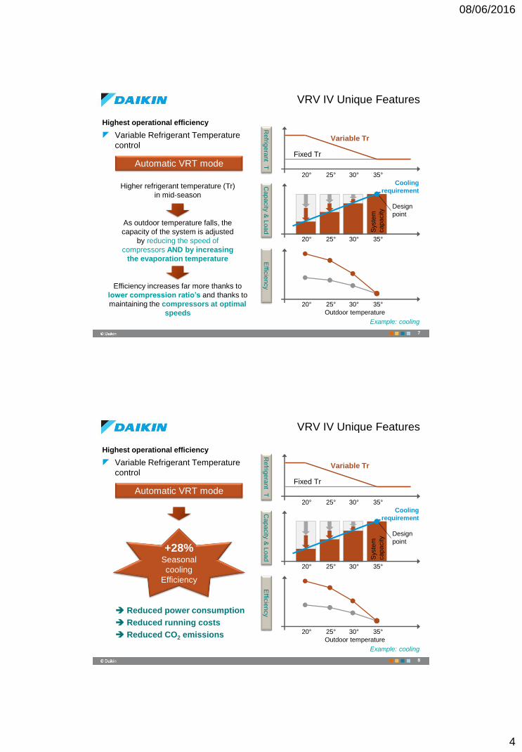
Highest operational efficiency
Variable Refrigerant Temperature
control
6
08/06/2016
4
Automatic VRT mode
Sys
tem
capacity
Refrig
era
nt T
35°25° 30°20°
Effic
iency
35°25° 30°20°
Outdoor temperature
Sys
tem
capacity
Fixed Tr
Higher refrigerant temperature (Tr)
in mid-season
As outdoor temperature falls, the
capacity of the system is adjusted
by reducing the speed of
compressors AND by increasing
the evaporation temperature
Efficiency increases far more thanks to
lower compression ratio’s and thanks to
maintaining the compressors at optimal
speeds
Variable Tr
Capacity &
Load
35°25° 30°20°
Cooling
requirement
Design
point
VRV IV Unique Features
Highest operational efficiency
Variable Refrigerant Temperature
control
7
Example: cooling
Automatic VRT mode
Refrig
era
nt T
35°25° 30°20°
Effic
iency
35°25° 30°20°
Outdoor temperature
Fixed Tr
Variable Tr
+28%Seasonal
cooling
Efficiency
Reduced power consumption
Reduced running costs
Reduced CO2 emissions
VRV IV Unique Features
Highest operational efficiency
Variable Refrigerant Temperature
control
8
Sys
tem
capacity
Sys
tem
capacity
Capacity &
Load
35°25° 30°20°
Cooling
requirement
Design
point
Example: cooling
08/06/2016
5
VRV IV Unique Features
4,0
4,5
5,0
5,5
6,0
6,5
7,0
7,5
8,0
8 10 12 14 16 18 20 22 24 26 28 30 32 34 36 38 40 42 44 46 48 50 52 54
ESEER comparison
ESEER (VRV III) ESEER (VRV IV)
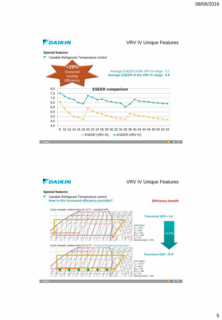
+28%Seasonal
cooling
Efficiency
Average ESEER of the VRV III range: 5.1
Average ESEER of the VRV IV range: 6.6
Special features
Variable Refrigerant Temperature control
9
Special features
Variable Refrigerant Temperature control
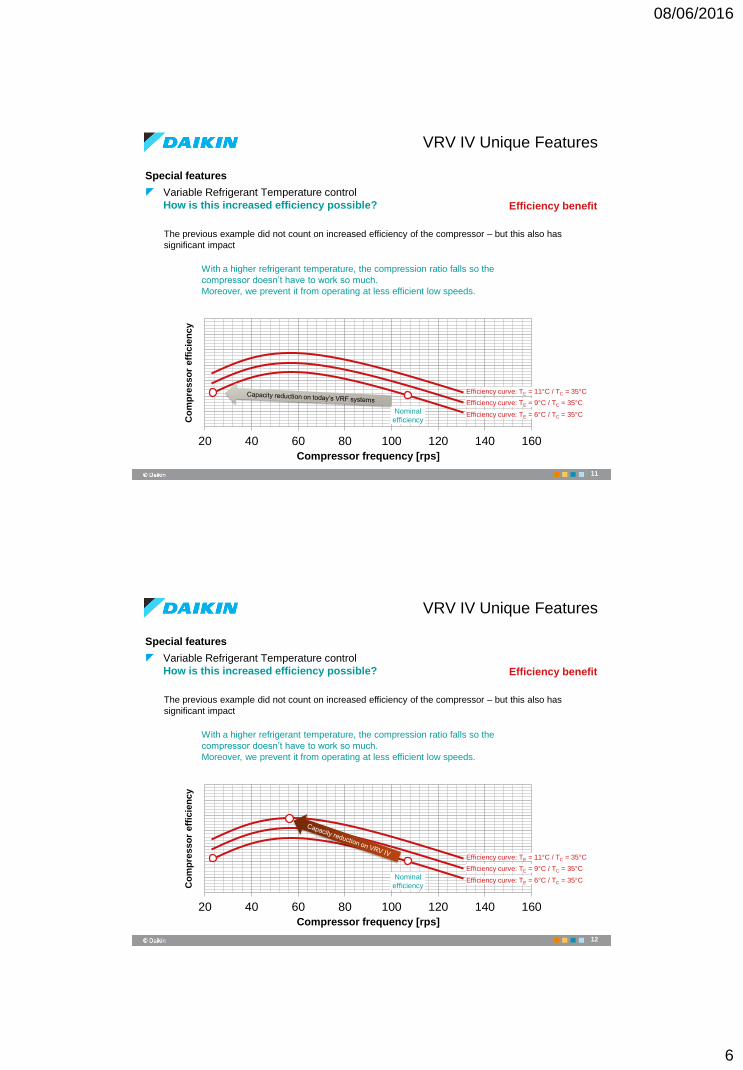
How is this increased efficiency possible? Efficiency benefit
Cycle example: outdoor temp 25~27°C – standard VRF
Cycle specs.:
TE = 6°CTC = 40°C
ΔTSH = 5K
ΔTSC = 20K
ηIS = 0.6
Heat loss factor = 10%
Theoretical EER = 4.6
Cycle example: outdoor temp 25~27°C – Increased refrigerant temperature
Cycle specs.:
TE = 11°CTC = 40°C
ΔTSH = 5K
ΔTSC = 16K
ηIS = 0.6
Heat loss factor = 10%
Theoretical EER = 5.4
+17%
VRV IV Unique Features
10
08/06/2016
6
20 40 60 80 100 120 140 160
Compressor frequency [rps]
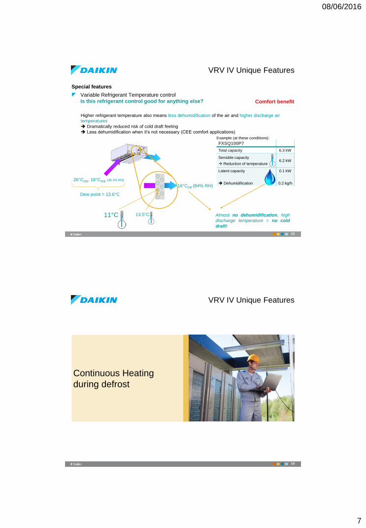
Special features
Variable Refrigerant Temperature control
How is this increased efficiency possible?
The previous example did not count on increased efficiency of the compressor – but this also has
significant impact
Co
mp
resso
r eff
icie
ncy
With a higher refrigerant temperature, the compression ratio falls so the
compressor doesn’t have to work so much.
Moreover, we prevent it from operating at less efficient low speeds.
VRV IV Unique Features
Nominal
efficiencyEfficiency curve: TE = 6°C / TC = 35°C
Efficiency curve: TE = 9°C / TC = 35°C
Efficiency curve: TE = 11°C / TC = 35°C
Efficiency benefit
11
20 40 60 80 100 120 140 160
Compressor frequency [rps]
Special features
Variable Refrigerant Temperature control
How is this increased efficiency possible?
With a higher refrigerant temperature, the compression ratio falls so the
compressor doesn’t have to work so much.
Moreover, we prevent it from operating at less efficient low speeds.
VRV IV Unique Features
Efficiency curve: TE = 6°C / TC = 35°C
Efficiency curve: TE = 9°C / TC = 35°C
Efficiency curve: TE = 11°C / TC = 35°C
The previous example did not count on increased efficiency of the compressor – but this also has
significant impact
Efficiency benefit
Co
mp
resso
r eff
icie
ncy
Nominal
efficiency
12
08/06/2016
7
Special features
Variable Refrigerant Temperature control
Is this refrigerant control good for anything else? Comfort benefit
26°CDB, 18°CWB (46.3% RH)
13.5°C
Dew point = 13.6°C
11°C
16°CDB (84% RH)
Almost no dehumidification, high
discharge temperature = no cold
draft!
FXSQ100P7
Total capacity 6.3 kW
Sensible capacity
Reduction of temperature6.2 kW
Latent capacity
Dehumidification
0.1 kW
0.2 kg/h
Higher refrigerant temperature also means less dehumidification of the air and higher discharge air
temperatures
Dramatically reduced risk of cold draft feeling
Less dehumidification when it’s not necessary (CEE comfort applications)
Example (at these conditions):
VRV IV Unique Features
13
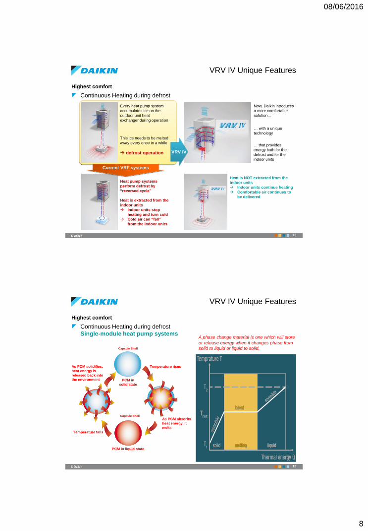
Continuous Heating
during defrost
14
VRV IV Unique Features
08/06/2016
8
Highest comfort
Continuous Heating during defrost
Every heat pump system
accumulates ice on the
outdoor unit heat
exchanger during operation
Heat pump systems
perform defrost by
“reversed cycle”
Heat is extracted from the
indoor units
Indoor units stop
heating and turn cold
Cold air can “fall”
from the indoor units
This ice needs to be melted
away every once in a while
defrost operation
Now, Daikin introduces
a more comfortable
solution…
… with a unique
technology
… that provides
energy both for the
defrost and for the
indoor units
Heat is NOT extracted from the
indoor units
Indoor units continue heating
Comfortable air continues to
be delivered
Current VRF systems
VRV IV
VRV IV Unique Features
15
Highest comfort
Continuous Heating during defrost
Single-module heat pump systems
As PCM absorbs
heat energy, it
melts
Temperature rises
PCM in liquid state
Capsule Shell
Temperature falls
PCM in
solid state
A phase change material is one which will store
or release energy when it changes phase from
solid to liquid or liquid to solid.Capsule Shell
As PCM solidifies,
heat energy is
released back into
the environment
VRV IV Unique Features
16
08/06/2016
9
VRV IV Unique Features
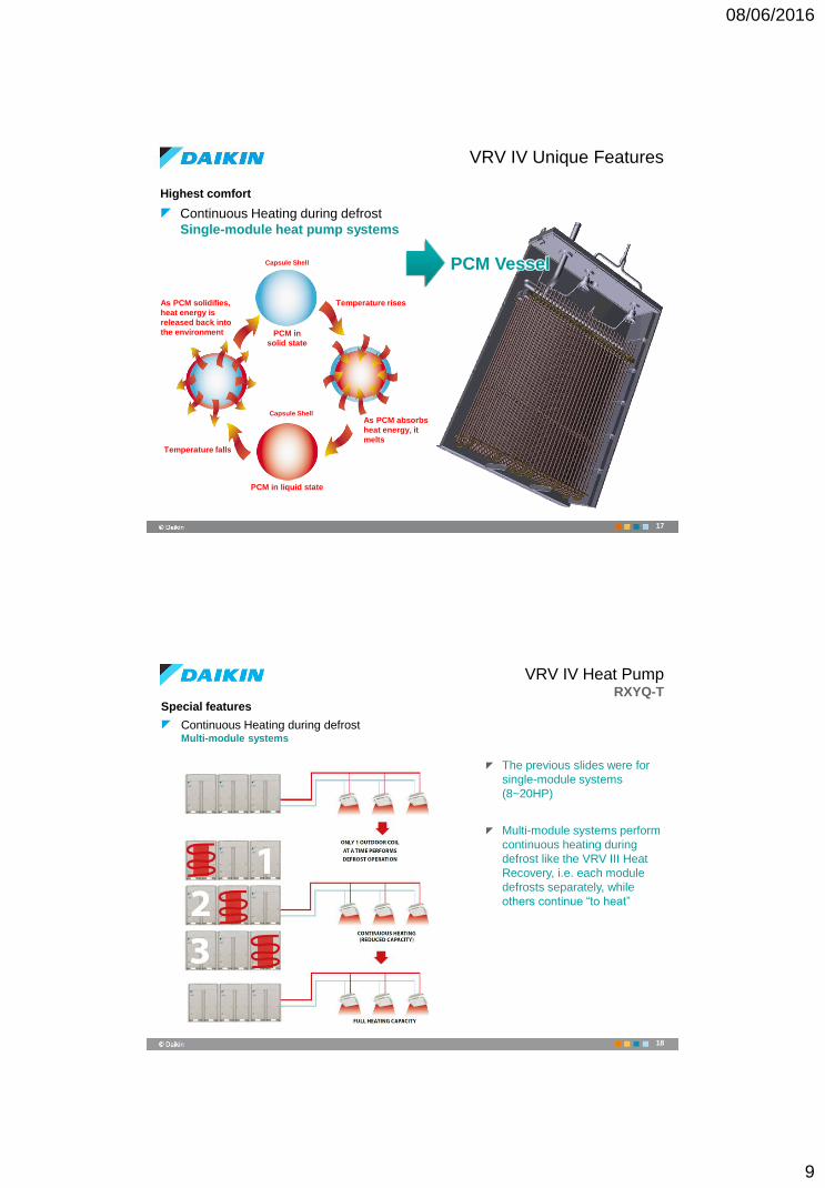
Highest comfort
Continuous Heating during defrost
Single-module heat pump systems
17
As PCM absorbs
heat energy, it
melts
Temperature rises
PCM in liquid state
Capsule Shell
Temperature falls
PCM in
solid state
Capsule Shell
As PCM solidifies,
heat energy is
released back into
the environment
PCM Vessel
VRV IV Heat PumpRXYQ-T
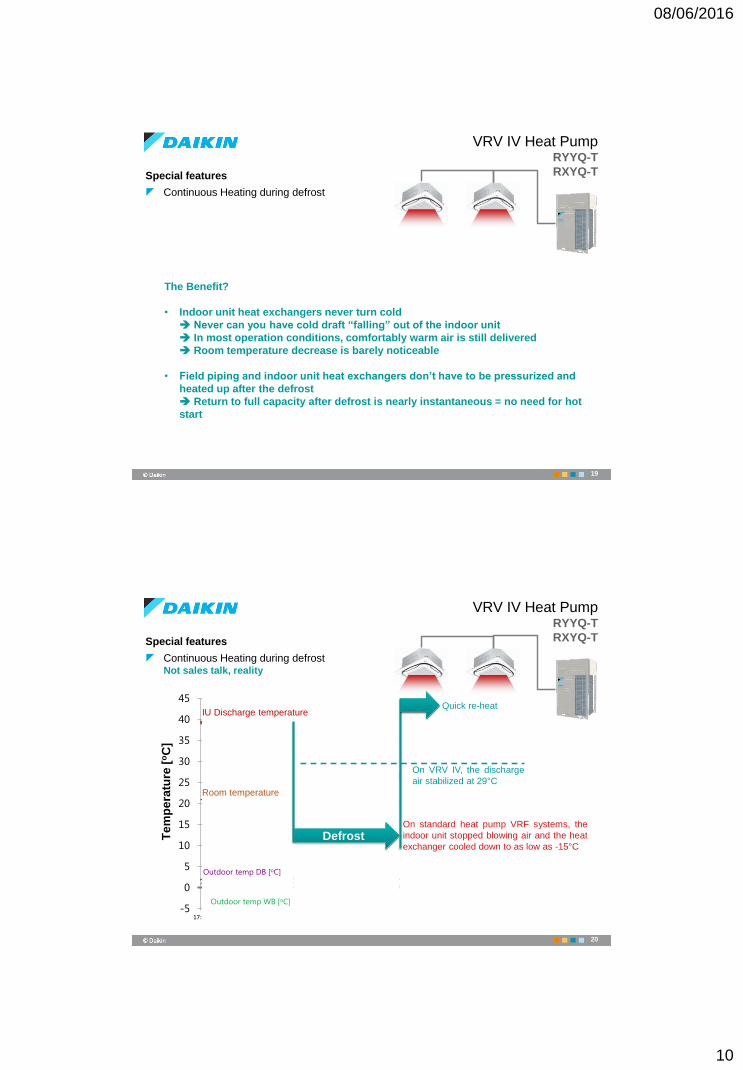
Special features
Continuous Heating during defrostMulti-module systems
The previous slides were for
single-module systems
(8~20HP)
Multi-module systems perform
continuous heating during
defrost like the VRV III Heat
Recovery, i.e. each module
defrosts separately, while
others continue “to heat”
18
08/06/2016
10
Special features
Continuous Heating during defrost
VRV IV Heat PumpRYYQ-T
RXYQ-T
The Benefit?
• Indoor unit heat exchangers never turn cold
Never can you have cold draft “falling” out of the indoor unit
In most operation conditions, comfortably warm air is still delivered
Room temperature decrease is barely noticeable
• Field piping and indoor unit heat exchangers don’t have to be pressurized and
heated up after the defrost
Return to full capacity after defrost is nearly instantaneous = no need for hot
start
19
-5
0
5
10
15
20
25
30
35
40
45
17:25 17:30 17:35 17:40 17:45 17:50 17:55 18:00 18:05
Special features
Continuous Heating during defrostNot sales talk, reality
Te
mp
era
ture
[oC
]
Outdoor temp WB [oC]
Outdoor temp DB [oC]
IU Discharge temperature
Room temperature
DefrostOn standard heat pump VRF systems, the
indoor unit stopped blowing air and the heat
exchanger cooled down to as low as -15°C
On VRV IV, the discharge
air stabilized at 29°C
Quick re-heat
VRV IV Heat PumpRYYQ-T
RXYQ-T
20
08/06/2016
11
VRV Configurator
21
VRV IV Unique Features
VRV IV Unique Features
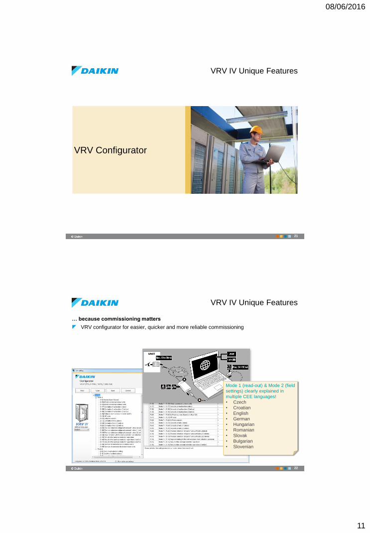
… because commissioning matters
VRV configurator for easier, quicker and more reliable commissioning
22
Mode 1 (read-out) & Mode 2 (field
settings) clearly explained in
multiple CEE languages!
• Czech
• Croatian
• English
• German
• Hungarian
• Romanian
• Slovak
• Bulgarian
• Slovenian
08/06/2016
12
Total Solution Systems
23
VRV IV Unique Features
VRV IV Unique Features
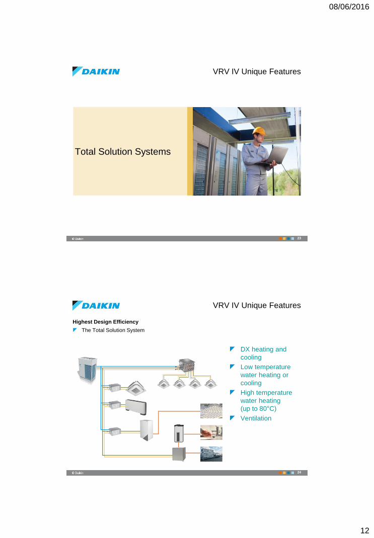
Highest Design Efficiency
The Total Solution System
DX heating and
cooling
Low temperature
water heating or
cooling
High temperature
water heating
(up to 80°C)
Ventilation
24
08/06/2016
13
VRV IV Unique Features
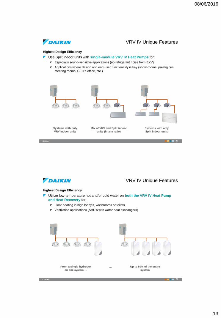
Highest Design Efficiency
Use Split indoor units with single-module VRV IV Heat Pumps for:
Especially sound-sensitive applications (no refrigerant noise from EXV)
Applications where design and end-user functionality is key (show-rooms, prestigious
meeting rooms, CEO’s office, etc.)
25
Systems with only
VRV indoor units
Mix of VRV and Split indoor
units (in any ratio)
Systems with only
Split indoor units
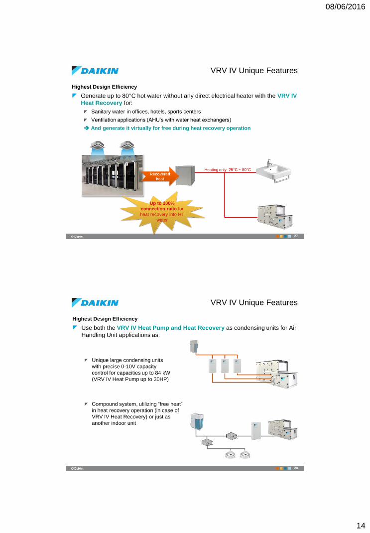
VRV IV Unique Features
Highest Design Efficiency
Utilize low-temperature hot and/or cold water on both the VRV IV Heat Pump
and Heat Recovery for:
Floor-heating in high lobby’s, washrooms or toilets
Ventilation applications (AHU’s with water heat exchangers)
26
From a single hydrobox
on one system …
Up to 80% of the entire
system
…
08/06/2016
14
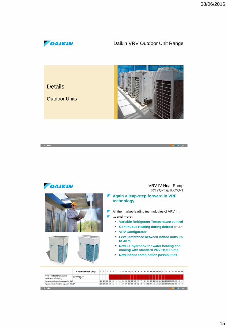
VRV IV Unique Features
Highest Design Efficiency
Generate up to 80°C hot water without any direct electrical heater with the VRV IV
Heat Recovery for:
Sanitary water in offices, hotels, sports centers
Ventilation applications (AHU’s with water heat exchangers)
And generate it virtually for free during heat recovery operation
Recovered
heat
Heating only: 25°C ~ 80°C
Up to 200%
connection ratio for
heat recovery into HT
water
27
VRV IV Unique Features
Highest Design Efficiency
Use both the VRV IV Heat Pump and Heat Recovery as condensing units for Air
Handling Unit applications as:
Unique large condensing units
with precise 0-10V capacity
control for capacities up to 84 kW
(VRV IV Heat Pump up to 30HP)
Compound system, utilizing “free heat”
in heat recovery operation (in case of
VRV IV Heat Recovery) or just as
another indoor unit
28
08/06/2016
15
Daikin VRV Outdoor Unit Range
Details
Outdoor Units
29
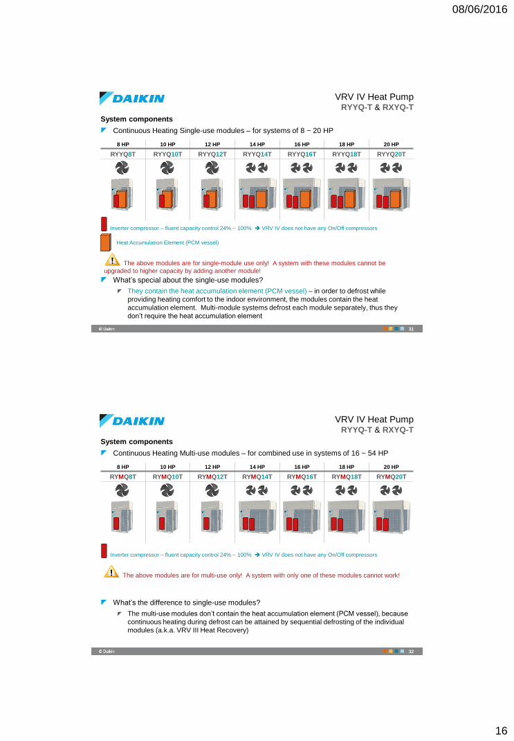
VRV IV Heat PumpRYYQ-T & RXYQ-T
Again a leap-step forward in VRF
technology
All the market-leading technologies of VRV III …
… and more:
Variable Refrigerant Temperature control
Continuous Heating during defrost (RYYQ-T)
VRV Configurator
Level difference between indoor units up
to 30 m!
New LT hydrobox for water heating and
cooling with standard VRV Heat Pump
New indoor combination possibilities
Capacity class [HP]: 4 5 6 8 10 12 14 16 18 20 22 24 26 28 30 32 34 36 38 40 42 44 46 48 50 52 54
VRV IV Heat Pump with
continuous heating RYYQ-T
Approximate cooling capacity [kW] * 12 14 16 22 28 34 40 45 49 56 62 67 71 77 83 89 94 98 105 111 116 120 126 132 138 143 147
Approximate heating capacity [kW] * 14 16 18 25 32 38 45 50 57 63 69 75 82 88 94 102 107 113 119 126 132 138 145 151 158 163 170
30
08/06/2016
16
System components
Continuous Heating Single-use modules – for systems of 8 ~ 20 HP
What’s special about the single-use modules?
They contain the heat accumulation element (PCM vessel) – in order to defrost while
providing heating comfort to the indoor environment, the modules contain the heat
accumulation element. Multi-module systems defrost each module separately, thus they
don’t require the heat accumulation element
VRV IV Heat PumpRYYQ-T & RXYQ-T
8 HP 10 HP 12 HP 14 HP 16 HP 18 HP 20 HP
RYYQ8T RYYQ10T RYYQ12T RYYQ14T RYYQ16T RYYQ18T RYYQ20T
Inverter compressor – fluent capacity control 24% ~ 100% VRV IV does not have any On/Off compressors
The above modules are for single-module use only! A system with these modules cannot be
upgraded to higher capacity by adding another module!
Heat Accumulation Element (PCM vessel)
31
System components
Continuous Heating Multi-use modules – for combined use in systems of 16 ~ 54 HP
What’s the difference to single-use modules?
The multi-use modules don’t contain the heat accumulation element (PCM vessel), because
continuous heating during defrost can be attained by sequential defrosting of the individual
modules (a.k.a. VRV III Heat Recovery)
VRV IV Heat PumpRYYQ-T & RXYQ-T
8 HP 10 HP 12 HP 14 HP 16 HP 18 HP 20 HP
RYMQ8T RYMQ10T RYMQ12T RYMQ14T RYMQ16T RYMQ18T RYMQ20T
Inverter compressor – fluent capacity control 24% ~ 100% VRV IV does not have any On/Off compressors
The above modules are for multi-use only! A system with only one of these modules cannot work!
32
08/06/2016
17
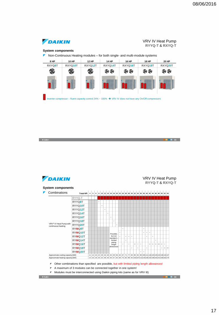
System components
Non-Continuous Heating modules – for both single- and multi-module systems
VRV IV Heat PumpRYYQ-T & RXYQ-T
8 HP 10 HP 12 HP 14 HP 16 HP 18 HP 20 HP
RXYQ8T RXYQ10T RXYQ12T RXYQ14T RXYQ16T RXYQ18T RXYQ20T
Inverter compressor – fluent capacity control 24% ~ 100% VRV IV does not have any On/Off compressors
33
System components
Combinations
Other combinations than specified are possible, but with limited piping length allowances!
A maximum of 3 modules can be connected together in one system!
Modules must be interconnected using Daikin piping kits (same as for VRV III)
VRV IV Heat PumpRYYQ-T & RXYQ-T
…
…Total HP: 4 5 6 8 10 12 14 16 18 20 22 24 26 28 30 32 34 36 38 40 42 44 46 48 50 52 54
VRV® IV Heat Pump with
continuous heating
RYYQ-T
RYYQ8T •
RYYQ10T •
RYYQ12T •
RYYQ14T •
RYYQ16T •
RYYQ18T •
RYYQ20T •
RYMQ8T
Possible,
but not
standard –
limited
piping
length
allowances
• •
RYMQ10T • • • •
RYMQ12T • • • • • •
RYMQ14T • •
RYMQ16T • • •• • • •• •• •• ••• •• •
RYMQ18T • • • • •• •••
RYMQ20T • •
Approximate cooling capacity [kW] 11 14 16 22 28 34 40 45 49 56 62 67 71 77 83 89 94 98 105 111 116 120 126 132 138 143 147
Approximate heating capacity [kW] 13 16 18 25 32 38 45 50 57 63 69 75 82 88 94 102 107 113 119 126 132 138 145 151 158 163 170
34
08/06/2016
18
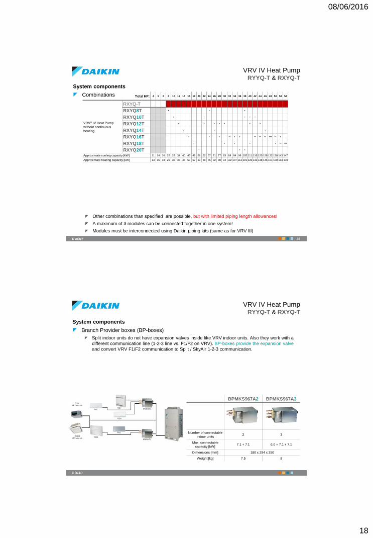
System components
Combinations
Other combinations than specified are possible, but with limited piping length allowances!
A maximum of 3 modules can be connected together in one system!
Modules must be interconnected using Daikin piping kits (same as for VRV III)
VRV IV Heat PumpRYYQ-T & RXYQ-T
…
…Total HP: 4 5 6 8 10 12 14 16 18 20 22 24 26 28 30 32 34 36 38 40 42 44 46 48 50 52 54
VRV® IV Heat Pump
without continuous
heating
RXYQ-T
RXYQ8T • • •
RXYQ10T • • • • •
RXYQ12T • • • • • • •
RXYQ14T • • •
RXYQ16T • • • •• • • •• •• •• ••• •• •
RXYQ18T • • • • • •• •••
RXYQ20T • • •
Approximate cooling capacity [kW] 11 14 16 22 28 34 40 45 49 56 62 67 71 77 83 89 94 98 105 111 116 120 126 132 138 143 147
Approximate heating capacity [kW] 13 16 18 25 32 38 45 50 57 63 69 75 82 88 94 102 107 113 119 126 132 138 145 151 158 163 170
35
VRV IV Heat PumpRYYQ-T & RXYQ-T
System components
Branch Provider boxes (BP-boxes)
Split indoor units do not have expansion valves inside like VRV indoor units. Also they work with a
different communication line (1-2-3 line vs. F1/F2 on VRV). BP-boxes provide the expansion valve
and convert VRV F1/F2 communication to Split / SkyAir 1-2-3 communication.
BPMKS967A2 BPMKS967A3
Number of connectable
indoor units2 3
Max. connectable
capacity [kW]7.1 + 7.1 6.0 + 7.1 + 7.1
Dimensions [mm] 180 x 294 x 350
Weight [kg] 7.5 8
08/06/2016
19
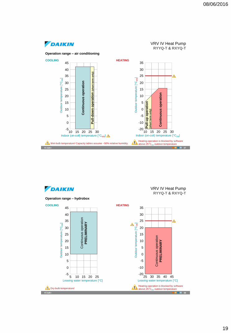
Operation range – air conditioning
VRV IV Heat PumpRYYQ-T & RXYQ-T
45
40
35
30
25
20
15
10
5
0
-510 15 20 25 30
Co
nti
nu
ou
s o
pe
rati
on
COOLING HEATING
Pu
ll-d
ow
n o
pe
rati
on
(s
ho
rt t
erm
on
ly)
Outd
oor
tem
pera
ture
[°C
DB]
Indoor (on-coil) temperature [°CWB]
Wet-bulb temperature! Capacity tables assume ~50% relative humidity.
35
30
25
20
15
10
5
0
-5
-10
-2010 15 20 25 30
Outd
oor
tem
pera
ture
[°C
WB]
Indoor (on-coil) temperature [°CDB]
Co
nti
nu
ou
s o
pe
rati
on
Pu
ll-u
p o
pe
rati
on
(s
ho
rt t
erm
on
ly)
Heating operation is blocked by software
above 25°CDB outdoor temperature
37
Operation range – hydrobox
VRV IV Heat PumpRYYQ-T & RXYQ-T
45
40
35
30
25
20
15
10
5
0
-55 10 15 20 25
Contin
uous o
pera
tio
n
PR
EL
IMIN
AR
Y
COOLING HEATING
Outd
oor
tem
pera
ture
[°C
DB]
Leaving water temperature [°C]
Dry-bulb temperature!
35
30
25
20
15
10
5
0
-5
-10
-2025 30 35 40 45
Outd
oor
tem
pera
ture
[°C
DB]
Heating operation is blocked by software
above 25°CDB outdoor temperature
Leaving water temperature [°C]
Contin
uous o
pera
tio
n
PR
EL
IMIN
AR
Y
38
08/06/2016
20
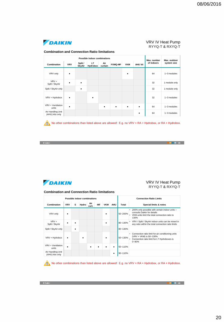
Combination and Connection Ratio limitations
VRV IV Heat PumpRYYQ-T & RXYQ-T
Possible indoor combinationsMax. number
of indoors
Max. outdoor
system sizeCombination VRV
Split /
SkyAir
LT
Hydrobox
Air
curtainFXMQ-MF VKM AHU kit
VRV only ● ● 64 1~3 modules
VRV +
Split / SkyAir● ● 32 1 module only
Split / SkyAir only ● 32 1 module only
VRV + Hydrobox ● ● 32 1~3 modules
VRV + Ventilation
units● ● ● ● ● 64 1~3 modules
Air Handling Unit
(AHU) kits only● 64 1~3 modules
No other combinations than listed above are allowed! E.g. no VRV + RA + Hydrobox, or RA + Hydrobox.
39
Combination and Connection Ratio limitations
VRV IV Heat PumpRYYQ-T & RXYQ-T
Possible indoor combinations Connection Ratio Limits
Combination VRV S HydroAir
curt.-MF VKM AHU Total Special limits & notes
VRV only ● ● 50~200%
• 200% only possible with certain indoor units –
consults Daikin for details
• VKM units limit the total connection ratio to
130%
VRV +
Split / SkyAir● ● ● 80~130%
• VRV / Split / SkyAir indoor units can be mixed in
any ratio within the total connection ratio limits
Split / SkyAir only ● 80~130%
VRV + Hydrobox ● ● ● 50~130%
• Connection ratio limit for air conditioning units
(VRV + VKM) is 50~130%
• Connection ratio limit for LT Hydroboxes is
0~80%
VRV + Ventilation
units● ● ● ● ● 50~110%
Air Handling Unit
(AHU) kits only● 90~110%
No other combinations than listed above are allowed! E.g. no VRV + RA + Hydrobox, or RA + Hydrobox.
40
08/06/2016
21
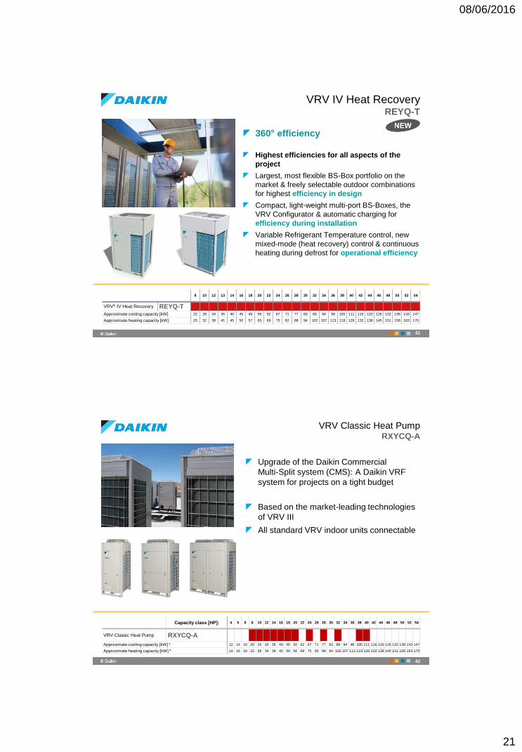
360° efficiency
Highest efficiencies for all aspects of the
project
Largest, most flexible BS-Box portfolio on the
market & freely selectable outdoor combinations
for highest efficiency in design
Compact, light-weight multi-port BS-Boxes, the
VRV Configurator & automatic charging for
efficiency during installation
Variable Refrigerant Temperature control, new
mixed-mode (heat recovery) control & continuous
heating during defrost for operational efficiency
…
…8 10 12 13 14 16 18 20 22 24 26 28 30 32 34 36 38 40 42 44 46 48 50 52 54
VRV® IV Heat Recovery REYQ-TApproximate cooling capacity [kW] 22 28 34 36 40 45 49 56 62 67 71 77 83 89 94 98 105 111 116 120 126 132 138 143 147
Approximate heating capacity [kW] 25 32 38 41 45 50 57 63 69 75 82 88 94 102 107 113 119 126 132 138 145 151 158 163 170
VRV IV Heat RecoveryREYQ-T
41
VRV Classic Heat PumpRXYCQ-A
Upgrade of the Daikin Commercial
Multi-Split system (CMS): A Daikin VRF
system for projects on a tight budget
Based on the market-leading technologies
of VRV III
All standard VRV indoor units connectable
Capacity class [HP]: 4 5 6 8 10 12 14 16 18 20 22 24 26 28 30 32 34 36 38 40 42 44 46 48 50 52 54
VRV Classic Heat Pump RXYCQ-A
Approximate cooling capacity [kW] * 12 14 16 20 25 30 35 40 45 50 62 67 71 77 83 89 94 98 105 111 116 120 126 132 138 143 147
Approximate heating capacity [kW] * 14 16 18 22 28 34 38 45 50 56 69 75 82 88 94 102 107 113 119 126 132 138 145 151 158 163 170
42
08/06/2016
22
43
‹#›© Daikin
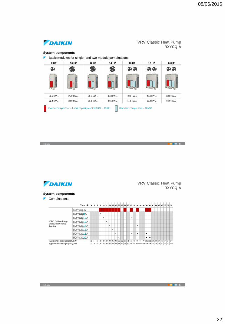
VRV Classic Heat PumpRXYCQ-A
System components
Basic modules for single- and two-module combinations
8 HP 10 HP 12 HP 14 HP 16 HP 18 HP 20 HP
20.0 kWCC 25.0 kWCC 30.0 kWCC 35.0 kWCC 40.0 kWCC 45.0 kWCC 50.0 kWCC
22.4 kWHC 28.0 kWHC 33.6 kWHC 37.5 kWHC 44.8 kWHC 50.4 kWHC 56.0 kWHC
Inverter compressor – fluent capacity control 24% ~ 100% Standard compressor – On/Off
44
‹#›© Daikin
VRV Classic Heat PumpRXYCQ-A
System components
Combinations
…
…Total HP: 4 5 6 8 10 12 14 16 18 20 22 24 26 28 30 32 34 36 38 40 42 44 46 48 50 52 54
VRV® IV Heat Pump
without continuous
heating
RXYCQ-A
RXYCQ8A •
RXYCQ10A • • •
RXYCQ12A •
RXYCQ14A • • •
RXYCQ16A •
RXYCQ18A • • • •
RXYCQ20A • • ••
Approximate cooling capacity [kW] 11 14 16 22 28 34 40 45 49 56 62 67 71 77 83 89 94 98 105 111 116 120 126 132 138 143 147
Approximate heating capacity [kW] 13 16 18 25 32 38 45 50 57 63 69 75 82 88 94 102 107 113 119 126 132 138 145 151 158 163 170
08/06/2016
23
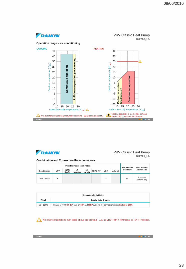
Operation range – air conditioning
VRV Classic Heat PumpRXYCQ-A
45
40
35
30
25
20
15
10
5
0
-510 15 20 25 30
Co
nti
nu
ou
s o
pe
rati
on
COOLING HEATING
Pu
ll-d
ow
n o
pe
rati
on
(s
ho
rt t
erm
on
ly)
Outd
oor
tem
pera
ture
[°C
DB]
Indoor (on-coil) temperature [°CWB]
Wet-bulb temperature! Capacity tables assume ~50% relative humidity.
35
30
25
20
15
10
5
0
-5
-10
-2010 15 20 25 30
Outd
oor
tem
pera
ture
[°C
WB]
Indoor (on-coil) temperature [°CDB]
Co
nti
nu
ou
s o
pe
rati
on
Pu
ll-u
p o
pe
rati
on
(s
ho
rt t
erm
on
ly)
Heating operation is blocked by software
above 25°CDB outdoor temperature
45
Combination and Connection Ratio limitations
VRV Classic Heat PumpRXYCQ-A
Possible indoor combinationsMax. number
of indoors
Max. outdoor
system sizeCombination VRV
Split /
SkyAir
LT
Hydrobox
Air
curtainFXMQ-MF VKM AHU kit
VRV Classic ● ● 641 module
systems only
No other combinations than listed above are allowed! E.g. no VRV + RA + Hydrobox, or RA + Hydrobox.
Connection Ratio Limits
Total Special limits & notes
50 ~ 120% • In case of FXFQ20~25A units on 8HP and 10HP systems, the connection ratio is limited to 100%
46
08/06/2016
24
47
‹#›© Daikin
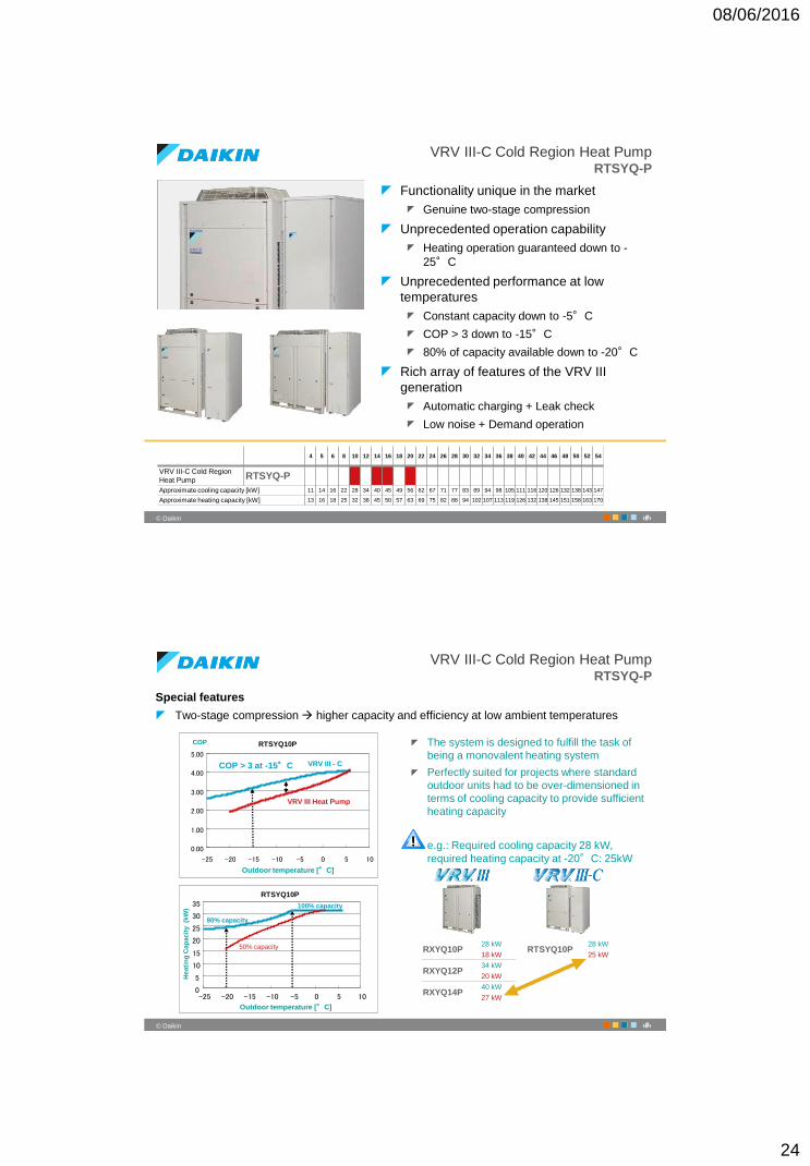
VRV III-C Cold Region Heat PumpRTSYQ-P
Functionality unique in the market
Genuine two-stage compression
Unprecedented operation capability
Heating operation guaranteed down to -
25°C
Unprecedented performance at low
temperatures
Constant capacity down to -5°C
COP > 3 down to -15°C
80% of capacity available down to -20°C
Rich array of features of the VRV III
generation
Automatic charging + Leak check
Low noise + Demand operation
…
…4 5 6 8 10 12 14 16 18 20 22 24 26 28 30 32 34 36 38 40 42 44 46 48 50 52 54
VRV III-C Cold Region
Heat Pump RTSYQ-P
Approximate cooling capacity [kW] 11 14 16 22 28 34 40 45 49 56 62 67 71 77 83 89 94 98 105 111 116 120 126 132 138 143 147
Approximate heating capacity [kW] 13 16 18 25 32 38 45 50 57 63 69 75 82 88 94 102 107 113 119 126 132 138 145 151 158 163 170
48
‹#›© Daikin
VRV III-C Cold Region Heat PumpRTSYQ-P
Special features
Two-stage compression higher capacity and efficiency at low ambient temperatures
The system is designed to fulfill the task of
being a monovalent heating system
Perfectly suited for projects where standard
outdoor units had to be over-dimensioned in
terms of cooling capacity to provide sufficient
heating capacity
e.g.: Required cooling capacity 28 kW,
required heating capacity at -20°C: 25kW
VRV III - CCOP > 3 at -15°C
Outdoor temperature [°C]
RTSYQ10P
0.00
1.00
2.00
3.00
4.00
5.00
-25 -20 -15 -10 -5 0 5 10
COP
VRV III Heat Pump
Heati
ng
Cap
acit
y (k
W) 100% capacity
80% capacity
50% capacity
0
5
10
15
20
25
30
35
-25 -20 -15 -10 -5 0 5 10
RTSYQ10P
Outdoor temperature [°C]
RXYQ10P28 kW
RTSYQ10P28 kW
18 kW 25 kW
RXYQ12P34 kW
20 kW
RXYQ14P40 kW
27 kW
08/06/2016
25
49
‹#›© Daikin
VRV III-C Cold Region Heat PumpRTSYQ-P
Special features
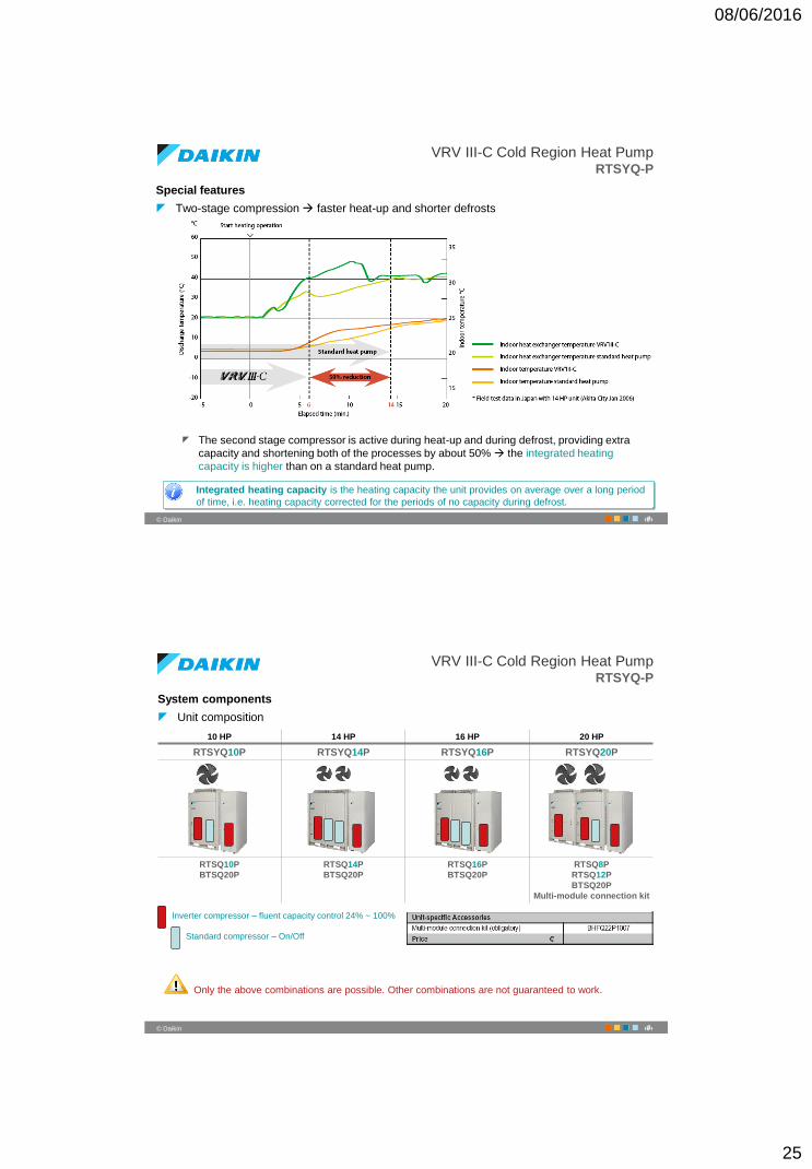
Two-stage compression faster heat-up and shorter defrosts
The second stage compressor is active during heat-up and during defrost, providing extra
capacity and shortening both of the processes by about 50% the integrated heating
capacity is higher than on a standard heat pump.
Integrated heating capacity is the heating capacity the unit provides on average over a long period
of time, i.e. heating capacity corrected for the periods of no capacity during defrost.
50
‹#›© Daikin
VRV III-C Cold Region Heat PumpRTSYQ-P
System components
Unit composition
10 HP 14 HP 16 HP 20 HP
RTSYQ10P RTSYQ14P RTSYQ16P RTSYQ20P
RTSQ10P
BTSQ20P
RTSQ14P
BTSQ20P
RTSQ16P
BTSQ20P
RTSQ8P
RTSQ12P
BTSQ20P
Multi-module connection kit
Inverter compressor – fluent capacity control 24% ~ 100%
Standard compressor – On/Off
Only the above combinations are possible. Other combinations are not guaranteed to work.
08/06/2016
26
51
‹#›© Daikin
VRV III-C Cold Region Heat PumpRTSYQ-P
System components
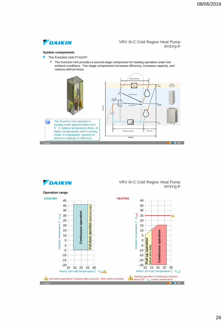
The Function Unit BTSQ20P
The Function Unit provides a second stage compressor for heating operation under low
ambient conditions. Two-stage compression increases efficiency, increases capacity, and
reduces defrost times.
The Function Unit operates in
heating mode approximately from
5°C outdoor temperature down. At
higher temperatures and in cooling
mode, it is bypassed, causing no
losses to capacity or efficiency.
52
‹#›© Daikin
VRV III-C Cold Region Heat PumpRTSYQ-P
Operation range
45
40
35
30
25
20
15
10
5
0
-5
10 15 20 25 30
COOLING HEATING
Outd
oor
tem
pera
ture
[°
CD
B]
Indoor (on-coil) temperature [°CWB]
Wet-bulb temperature! Capacity tables assume ~50% relative humidity.
10 15 20 25 30
Outd
oor
tem
pera
ture
[°
CW
B]
Indoor (on-coil) temperature [°CDB]
Heating operation is blocked by software
above 25°CDB outdoor temperature
-10
-15
-20
Co
nti
nu
ou
s o
pe
rati
on
Pu
ll-d
ow
n o
pera
tio
n (
sh
ort
term
on
ly)
40
35
30
25
20
15
10
5
0
-5
-10
-15
-20
-25
Pu
ll-u
p o
pe
rati
on
(s
ho
rt t
erm
on
ly)
Co
nti
nu
ou
s o
pe
rati
on
08/06/2016
27
53
‹#›© Daikin
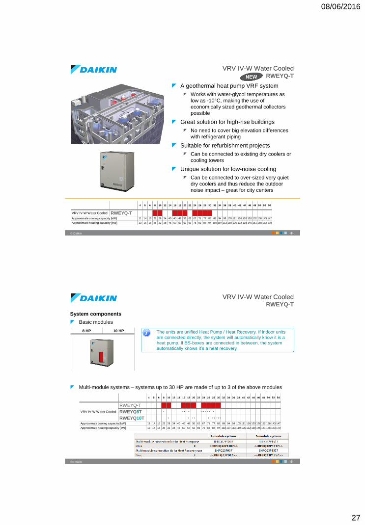
VRV IV-W Water CooledRWEYQ-T
A geothermal heat pump VRF system
Works with water-glycol temperatures as
low as -10°C, making the use of
economically sized geothermal collectors
possible
Great solution for high-rise buildings
No need to cover big elevation differences
with refrigerant piping
Suitable for refurbishment projects
Can be connected to existing dry coolers or
cooling towers
Unique solution for low-noise cooling
Can be connected to over-sized very quiet
dry coolers and thus reduce the outdoor
noise impact – great for city centers
…
…4 5 6 8 10 12 14 16 18 20 22 24 26 28 30 32 34 36 38 40 42 44 46 48 50 52 54
VRV IV-W Water Cooled RWEYQ-TApproximate cooling capacity [kW] 11 14 16 22 28 34 40 45 49 56 62 67 71 77 83 89 94 98 105 111 116 120 126 132 138 143 147
Approximate heating capacity [kW] 13 16 18 25 32 38 45 50 57 63 69 75 82 88 94 102 107 113 119 126 132 138 145 151 158 163 170
54
‹#›© Daikin
VRV IV-W Water CooledRWEYQ-T
System components
Basic modules
Multi-module systems – systems up to 30 HP are made of up to 3 of the above modules
8 HP 10 HP
…
…4 5 6 8 10 12 14 16 18 20 22 24 26 28 30 32 34 36 38 40 42 44 46 48 50 52 54
VRV IV-W Water Cooled
RWEYQ-T
RWEYQ8T • • • • • • • • • •
RWEYQ10T • • • • • • • • • •
Approximate cooling capacity [kW] 11 14 16 22 28 34 40 45 49 56 62 67 71 77 83 89 94 98 105 111 116 120 126 132 138 143 147
Approximate heating capacity [kW] 13 16 18 25 32 38 45 50 57 63 69 75 82 88 94 102 107 113 119 126 132 138 145 151 158 163 170
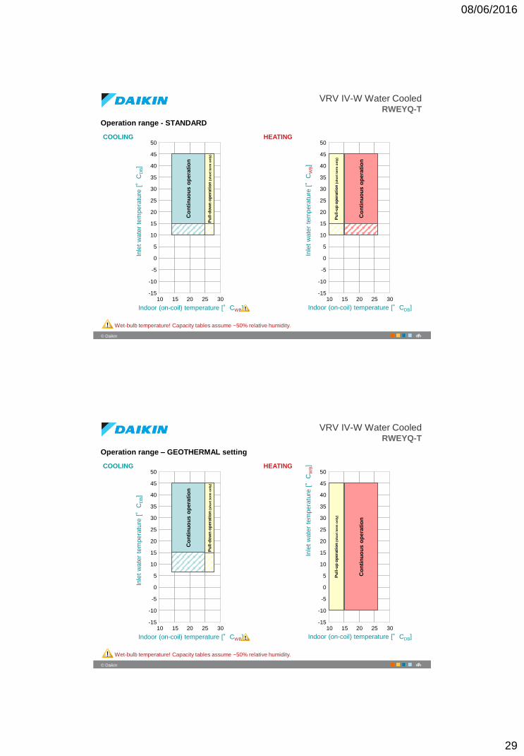
The units are unified Heat Pump / Heat Recovery. If indoor units
are connected directly, the system will automatically know it is a
heat pump. If BS-boxes are connected in between, the system
automatically knows it’s a heat recovery.
08/06/2016
28
55
‹#›© Daikin
VRV IV-W Water CooledRWEYQ-T
Special features
Double heat recovery possible
The unique concept of the water-cooled VRV gives the opportunity to recovery energy not just
within one VRV system in heat recovery mode, but also in between several separate systems
via the water loop
56
‹#›© Daikin
VRV IV-W Water CooledRWEYQ-T
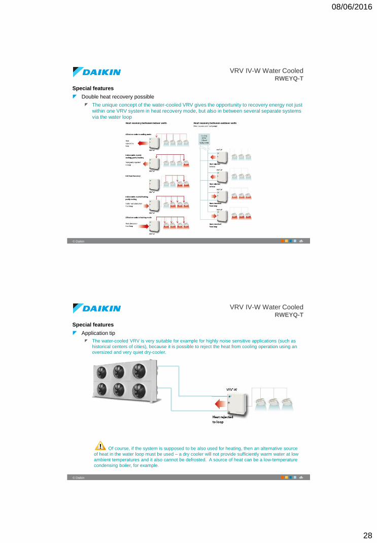
Special features
Application tip
The water-cooled VRV is very suitable for example for highly noise sensitive applications (such as
historical centers of cities), because it is possible to reject the heat from cooling operation using an
oversized and very quiet dry-cooler.
Of course, if the system is supposed to be also used for heating, then an alternative source
of heat in the water loop must be used – a dry cooler will not provide sufficiently warm water at low
ambient temperatures and it also cannot be defrosted. A source of heat can be a low-temperature
condensing boiler, for example.
08/06/2016
29
57
‹#›© Daikin
VRV IV-W Water CooledRWEYQ-T
Operation range - STANDARD
45
40
35
30
25
20
15
10
5
0
-5
10 15 20 25 30
COOLING HEATINGIn
let
wate
r te
mpera
ture
[°
CD
B]
Indoor (on-coil) temperature [°CWB]
Wet-bulb temperature! Capacity tables assume ~50% relative humidity.
Inle
t w
ate
r te
mpera
ture
[°
CW
B]
Indoor (on-coil) temperature [°CDB]
50
-10
-15
45
40
35
30
25
20
15
10
5
0
-5
10 15 20 25 30
50
-10
-15
Co
nti
nu
ou
s o
pe
rati
on
Pu
ll-d
ow
n o
pera
tio
n (
sh
ort
term
on
ly)
Co
nti
nu
ou
s o
pe
rati
on
Pu
ll-u
p o
pera
tio
n (
sh
ort
term
on
ly)
58
‹#›© Daikin
VRV IV-W Water CooledRWEYQ-T
Operation range – GEOTHERMAL setting
45
40
35
30
25
20
15
10
5
0
-5
10 15 20 25 30
COOLING HEATING
Inle
t w
ate
r te
mpera
ture
[°
CD
B]
Indoor (on-coil) temperature [°CWB]
Wet-bulb temperature! Capacity tables assume ~50% relative humidity.
Inle
t w
ate
r te
mpera
ture
[°
CW
B]
Indoor (on-coil) temperature [°CDB]
50
-10
-15
45
40
35
30
25
20
15
10
5
0
-5
10 15 20 25 30
50
-10
-15
Co
nti
nu
ou
s o
pe
rati
on
Pu
ll-d
ow
n o
pera
tio
n (
sh
ort
term
on
ly)
Co
nti
nu
ou
s o
pe
rati
on
Pu
ll-u
p o
pera
tio
n (
sh
ort
term
on
ly)
08/06/2016
30
59
‹#›© Daikin
VRV IV-W Water CooledRWEYQ-T
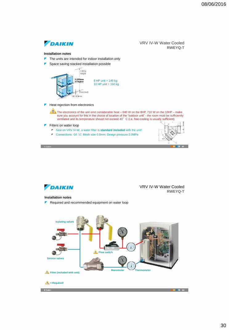
Installation notes
The units are intended for indoor installation only
Space saving stacked installation possible
Heat rejection from electronics
Filters on water loop
New on VRV IV-W, a water filter is standard included with the unit!
Connections: G1 ¼”; Mesh size 0.5mm; Design pressure 2.0MPa
8 HP unit = 149 kg
10 HP unit = 150 kg
The electronics of the unit emit considerable heat – 640 W on the 8HP, 710 W on the 10HP – make
sure you account for this in the choice of location of the “outdoor unit” - the room must be sufficiently
ventilated and its temperature should not exceed 40°C (i.e. free-cooling is usually sufficient)
VRV IV-W Water CooledRWEYQ-T
Installation notes
Required and recommended equipment on water loop
Filter (included with unit)Thermometer
Isolating valves
Service valves
Flow switch
Manometer
= Required!
60
08/06/2016
31
VRV IV-W Water CooledRWEYQ-T
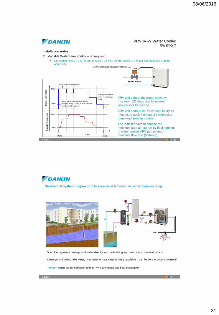
Installation notes
Variable Water Flow control – on request
On request, the VRV IV-W can provide a 13-step control signal to a motor-operated valve on the
water loop
61
VRV unit control the motor valve by
maximum 13 steps due to inverter
compressor frequency.
VRV unit change the valve step every 15
minutes to avoid hunting of compressor,
pump and another control.
The installer have to choose the
minimum step at test run by field settings
of water cooled VRV pcb to keep
minimum flow rate (50lt/min).Time
Mo
tor
valv
e st
epIn
vert
er f
req
uen
cy Max
Min
Max
Min
Connection cable (weak voltage)
Motor valve
First 15min.is always max.
start stop
Motor valve opening ratio will be changed every 15 min. due to inverter compressor frequency
During compressor stop, valve always close
Open loop systems draw ground water directly into the building and heat or cool the heat pumps.
When ground water, lake water, river water or sea water is freely available it can be very economic to use it!
Remark: watch out for corrosion and dirt => if any doubt use heat exchanger!!
Geothermal system in open loop to keep water temperature within operation range
08/06/2016
32
The Geothermal systems utilize the heat accumulated
in ground (this heat is continually supplied by sun).
At a depth of approximately 10 meters the ground
temperature remains fairly constant with an average
temperature between 10-20°C year-round (Europe),
depending on the region, terrain and soil type.
Horizontal loops run piping
parallel and close to the surface
(1-2 m).
The undisturbed ground
temperature naturally change with
the seasons.
Vertical loops run perpendicular to the surface and
the holes can be several hundred meters deep (80-
200 m). At these depths, the undisturbed ground
temperature does not change throughout the year.
Geothermal system in closed loop to keep water temperature within operation range
64
‹#›© Daikin
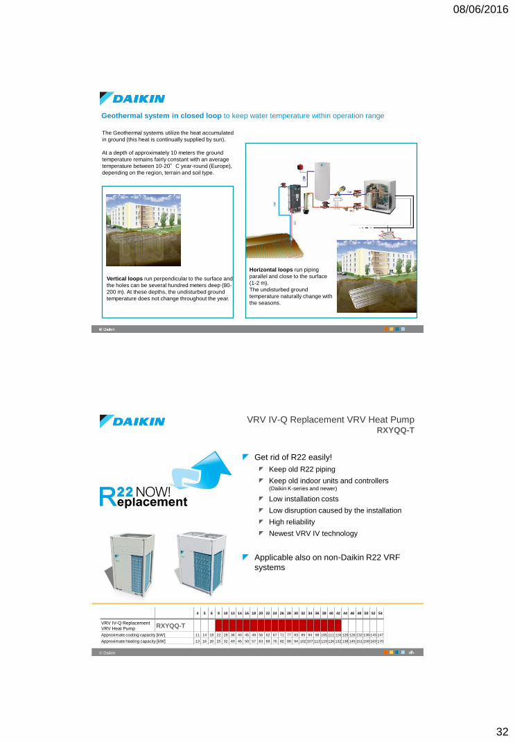
VRV IV-Q Replacement VRV Heat PumpRXYQQ-T
Get rid of R22 easily!
Keep old R22 piping
Keep old indoor units and controllers (Daikin K-series and newer)
Low installation costs
Low disruption caused by the installation
High reliability
Newest VRV IV technology
Applicable also on non-Daikin R22 VRF
systems
…
…4 5 6 8 10 13 14 16 18 20 22 24 26 28 30 32 34 36 38 40 42 44 46 48 50 52 54
VRV IV-Q Replacement
VRV Heat Pump RXYQQ-T
Approximate cooling capacity [kW] 11 14 18 22 28 36 40 45 49 56 62 67 71 77 83 89 94 98 105 111 116 120 126 132 138 143 147
Approximate heating capacity [kW] 13 16 20 25 32 40 45 50 57 63 69 75 82 88 94 102 107 113 119 126 132 138 145 151 158 163 170
08/06/2016
33
65
‹#›© Daikin
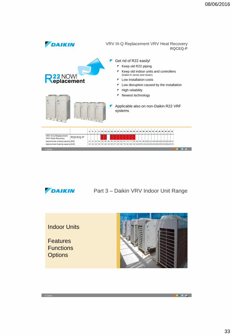
VRV III-Q Replacement VRV Heat RecoveryRQCEQ-P
Get rid of R22 easily!
Keep old R22 piping
Keep old indoor units and controllers (Daikin K-series and newer)
Low installation costs
Low disruption caused by the installation
High reliability
Newest technology
Applicable also on non-Daikin R22 VRF
systems
…
…4 5 6 8 10 13 14 16 18 20 22 24 26 28 30 32 34 36 38 40 42 44 46 48 50 52 54
VRV III-Q Replacement
VRV Heat Recovery RQCEQ-P
Approximate cooling capacity [kW] 11 14 16 22 28 36 40 45 49 56 62 67 71 77 83 89 94 98 105 111 116 120 126 132 138 143 147
Approximate heating capacity [kW] 13 16 18 25 32 40 45 50 57 63 69 75 82 88 94 102 107 113 119 126 132 138 145 151 158 163 170
66
‹#›© Daikin
Part 3 – Daikin VRV Indoor Unit Range
Indoor Units
Features
Functions
Options
6
08/06/2016
34
67
‹#›© Daikin
914222629313743495157596878
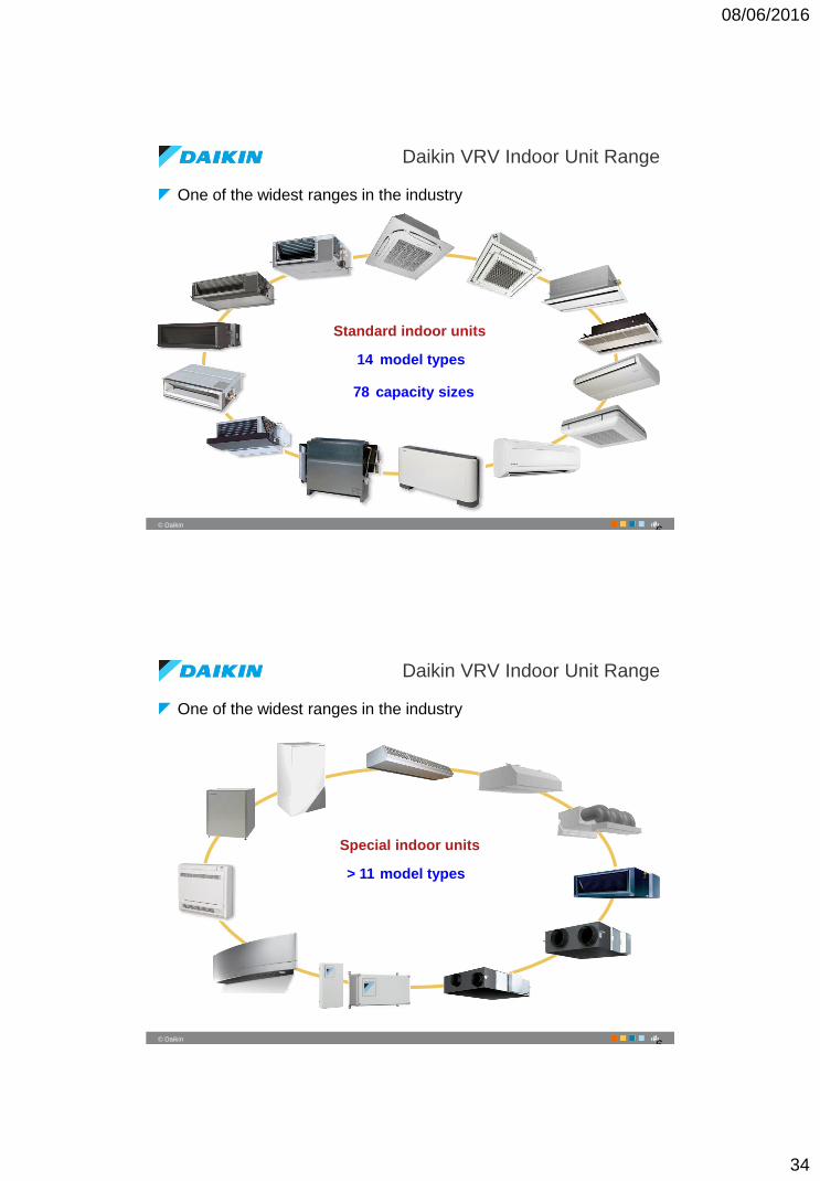
One of the widest ranges in the industry
Daikin VRV Indoor Unit Range
1234567891011121314 model types
capacity sizes
Standard indoor units
6
68
‹#›© Daikin
One of the widest ranges in the industry
Daikin VRV Indoor Unit Range
> 11 model types
Special indoor units
6
08/06/2016
35
69
‹#›© Daikin
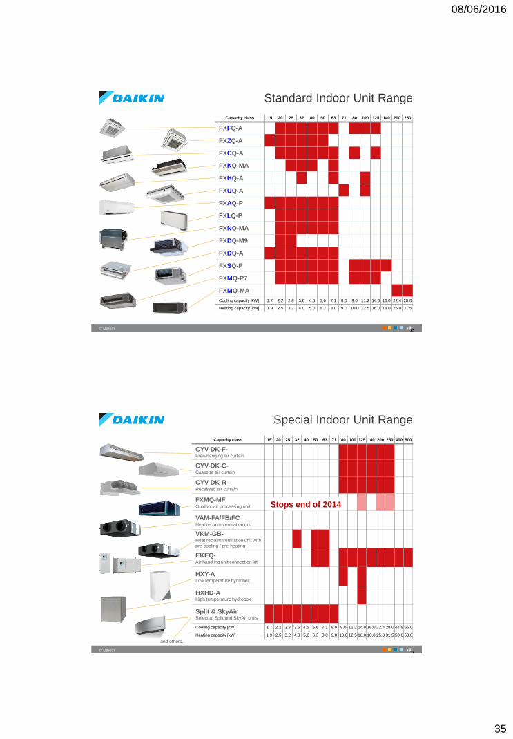
Standard Indoor Unit Range
Capacity class 15 20 25 32 40 50 63 71 80 100 125 140 200 250
FXFQ-A
FXZQ-A
FXCQ-A
FXKQ-MA
FXHQ-A
FXUQ-A
FXAQ-P
FXLQ-P
FXNQ-MA
FXDQ-M9
FXDQ-A
FXSQ-P
FXMQ-P7
FXMQ-MA
Cooling capacity [kW] 1.7 2.2 2.8 3.6 4.5 5.6 7.1 8.0 9.0 11.2 14.0 16.0 22.4 28.0
Heating capacity [kW] 1.9 2.5 3.2 4.0 5.0 6.3 8.0 9.0 10.0 12.5 16.0 18.0 25.0 31.5
6
70
‹#›© Daikin
Special Indoor Unit Range
Capacity class 15 20 25 32 40 50 63 71 80 100 125 140 200 250 400 500
CYV-DK-F-Free-hanging air curtain
CYV-DK-C-Cassette air curtain
CYV-DK-R-Recessed air curtain
FXMQ-MFOutdoor air processing unit
VAM-FA/FB/FCHeat reclaim ventilation unit
VKM-GB-Heat reclaim ventilation unit with
pre-cooling / pre-heating
EKEQ-Air handling unit connection kit
HXY-ALow temperature hydrobox
HXHD-AHigh temperature hydrobox
Split & SkyAir Selected Split and SkyAir units
Cooling capacity [kW] 1.7 2.2 2.8 3.6 4.5 5.6 7.1 8.0 9.0 11.2 14.0 16.0 22.4 28.0 44.8 56.0
Heating capacity [kW] 1.9 2.5 3.2 4.0 5.0 6.3 8.0 9.0 10.0 12.5 16.0 18.0 25.0 31.5 50.0 63.0
and others…
7
Stops end of 2014
08/06/2016
36
71
‹#›© Daikin
Part 3 – Daikin VRV Indoor Unit Range
Details
Standard Units
7
72
‹#›© Daikin
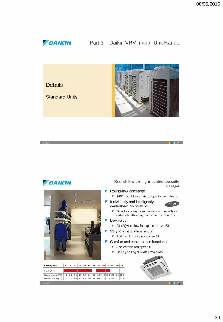
Round-flow ceiling mounted cassetteFXFQ-A
Round-flow discharge
360° out-blow of air, unique in the industry
Individually and intelligently
controllable swing-flaps
Direct air away from persons – manually or
automatically using the presence sensors
Low noise
28 dB(A) on low fan speed till size 63
Very low installation height
214 mm for units up to size 63
Comfort and convenience functions
3 selectable fan speeds
Ceiling soiling & Draft prevention
Capacity class 20 25 32 40 50 63 71 80 100 125 140 200 250
FXFQ-A
Cooling capacity [kW] 2.2 2.8 3.6 4.5 5.6 7.1 8.0 9.0 11.2 14.0 16.0 22.4 28.0
Heating capacity [kW] 2.5 3.2 4.0 5.0 6.3 8.0 9.0 10.0 12.5 16.0 18.0 25.0 31.5
7
08/06/2016
37
73
‹#›© Daikin
Round-flow ceiling mounted cassetteFXFQ-A
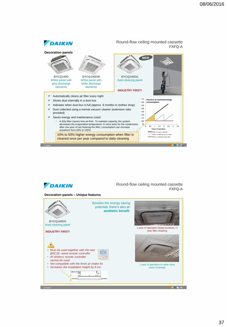
Decoration panels
BYCQ140D
White panel with
grey discharge
elements
BYCQ140DW
White panel with
white discharge
elements
BYCQ140DG
Auto-cleaning panel
INDUSTRY FIRST!
Automatically cleans air filter every night
Stores dust internally in a dust box
Indicates when dust box is full (approx. 6 months in clothes shop)
Dust collected using a normal vacuum cleaner (extension tube
provided)
Saves energy and maintenance costs!
• A dirty filter causes less air flow. To maintain capacity, the system
decreases the evaporation temperature more work for the compressor,
after one year of not cleaning the filter, consumption can increase
anywhere from 20% to 100%
90
100
110
120
130
140
150
160
170
0 0,5 1 1,5 2 2,5 3 3,5
Years of operation
Filter is never cleaned
Filter is cleaned once a year
Filter is cleaned every day
Percent of nominal energy
consumption
10% to 50% higher energy consumption when filter is
cleaned once per year compared to daily cleaning
7
74
‹#›© Daikin
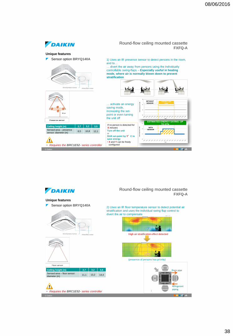
Round-flow ceiling mounted cassetteFXFQ-A
Decoration panels – Unique features
BYCQ140DG
Auto-cleaning panel
INDUSTRY FIRST!
• Must be used together with the new
BRC1E- wired remote controller
• IR wireless remote controller
cannot be used
• Not compatible with the fresh air intake kit
• Increases the installation height by 8 cm
Besides the energy saving
potential, there’s also an
aesthetic benefit:
1 year of operation (dusty location), ½
year filter cleaning
1 year of operation in same shop
(auto-cleaning)
7
08/06/2016
38
75
‹#›© Daikin
Round-flow ceiling mounted cassetteFXFQ-A
Unique features
Sensor option BRYQ140A
20
22
24
26
insi
de
te
mp
era
ture
[°C
DB
]
Time
WITHOUT
SENSOR
WITH
SENSOR
nobody in the
room
ESTIMATED ENERGY SAVING: UP
TO 27%
1) Uses an IR presence sensor to detect persons in the room,
and to…
… divert the air away from persons using the individually
controllable swing-flaps – Especially useful in heating
mode, where air is normally blown down to prevent
stratification
… activate an energy
saving mode,
increasing the set-
point or even turning
the unit off
• Requires the BRC1E52- series controller
If no person is detected for
X minutes
Turn off the unit
or
Shift set-point by Y°C to
save energy
• X and Y can be freely
configured
Ceiling height (m) 2,7 3,2 3,5
Sensed area – presence
sensor: diameter (m)8,5 10,8 12,1
7
76
‹#›© Daikin
Round-flow ceiling mounted cassetteFXFQ-A
Unique features
Sensor option BRYQ140A2) Uses an IR floor temperature sensor to detect potential air
stratification and uses the individual swing flap control to
divert the air to compensate
High air stratification effect detected
• Requires the BRC1E52- series controller
Ceiling height (m) 2,7 3,2 3,5
Sensed area – floor sensor:
diameter (m)11,1 13,2 14,4
Refrigerant piping
Drain pipe
(presence of persons has priority)
7
08/06/2016
39
77
‹#›© Daikin
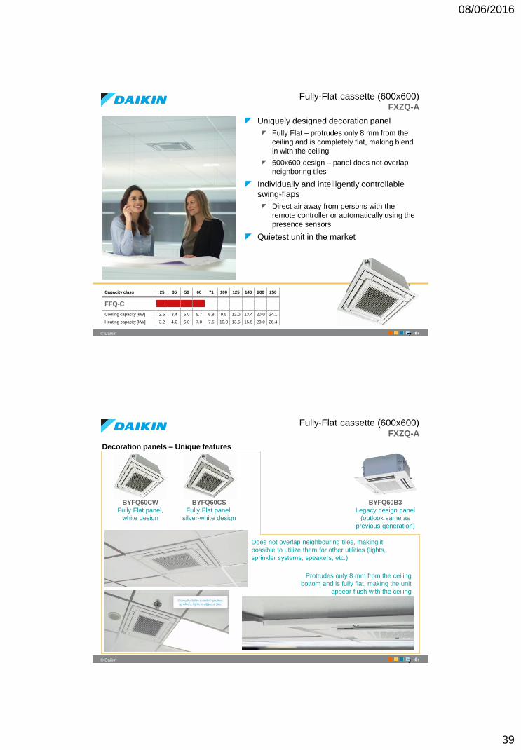
Fully-Flat cassette (600x600)FXZQ-A
Uniquely designed decoration panel
Fully Flat – protrudes only 8 mm from the
ceiling and is completely flat, making blend
in with the ceiling
600x600 design – panel does not overlap
neighboring tiles
Individually and intelligently controllable
swing-flaps
Direct air away from persons with the
remote controller or automatically using the
presence sensors
Quietest unit in the market
Capacity class 25 35 50 60 71 100 125 140 200 250
FFQ-C
Cooling capacity [kW] 2.5 3.4 5.0 5.7 6.8 9.5 12.0 13.4 20.0 24.1
Heating capacity [kW] 3.2 4.0 6.0 7.0 7.5 10.8 13.5 15.5 23.0 26.4
7
78
‹#›© Daikin
Fully-Flat cassette (600x600)FXZQ-A
Decoration panels – Unique features
BYFQ60CW
Fully Flat panel,
white design
BYFQ60CS
Fully Flat panel,
silver-white design
BYFQ60B3
Legacy design panel
(outlook same as
previous generation)
Does not overlap neighbouring tiles, making it
possible to utilize them for other utilities (lights,
sprinkler systems, speakers, etc.)
Protrudes only 8 mm from the ceiling
bottom and is fully flat, making the unit
appear flush with the ceiling
7
08/06/2016
40
79
‹#›© Daikin
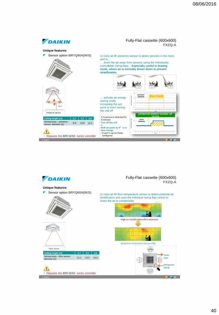
Fully-Flat cassette (600x600)FXZQ-A
Unique features
Sensor option BRYQ60A(W/S)
20
22
24
26
insi
de
te
mp
era
ture
[°C
DB
]
Time
WITHOUT
SENSOR
WITH
SENSOR
nobody in the
room
ESTIMATED ENERGY SAVING: UP
TO 27%
1) Uses an IR presence sensor to detect persons in the room,
and to…
… divert the air away from persons using the individually
controllable swing-flaps – Especially useful in heating
mode, where air is normally blown down to prevent
stratification
… activate an energy
saving mode,
increasing the set-
point or even turning
the unit off
• Requires the BRC1E52- series controller
If no person is detected for
X minutes
Turn off the unit
or
Shift set-point by Y°C to
save energy
• X and Y can be freely
configured
Ceiling height (m) 2,7 3,2 3,5
Sensed area – presence
sensor: diameter (m)8,5 10,8 12,1
7
80
‹#›© Daikin
Fully-Flat cassette (600x600)FXZQ-A
Unique features
Sensor option BRYQ60A(W/S)2) Uses an IR floor temperature sensor to detect potential air
stratification and uses the individual swing flap control to
divert the air to compensate
High air stratification effect detected
• Requires the BRC1E52- series controller
Ceiling height (m) 2,7 3,2 3,5
Sensed area – floor sensor:
diameter (m)11,1 13,2 14,4
(presence of persons has priority)
Refrigerant piping
Drain pipe
8
08/06/2016
41
81
‹#›© Daikin
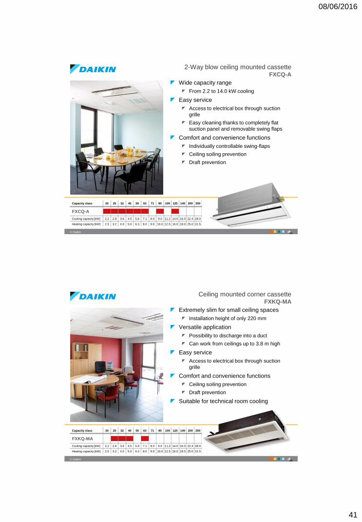
2-Way blow ceiling mounted cassetteFXCQ-A
Wide capacity range
From 2.2 to 14.0 kW cooling
Easy service
Access to electrical box through suction
grille
Easy cleaning thanks to completely flat
suction panel and removable swing flaps
Comfort and convenience functions
Individually controllable swing-flaps
Ceiling soiling prevention
Draft prevention
Capacity class 20 25 32 40 50 63 71 80 100 125 140 200 250
FXCQ-A
Cooling capacity [kW] 2.2 2.8 3.6 4.5 5.6 7.1 8.0 9.0 11.2 14.0 16.0 22.4 28.0
Heating capacity [kW] 2.5 3.2 4.0 5.0 6.3 8.0 9.0 10.0 12.5 16.0 18.0 25.0 31.5
8
82
‹#›© Daikin
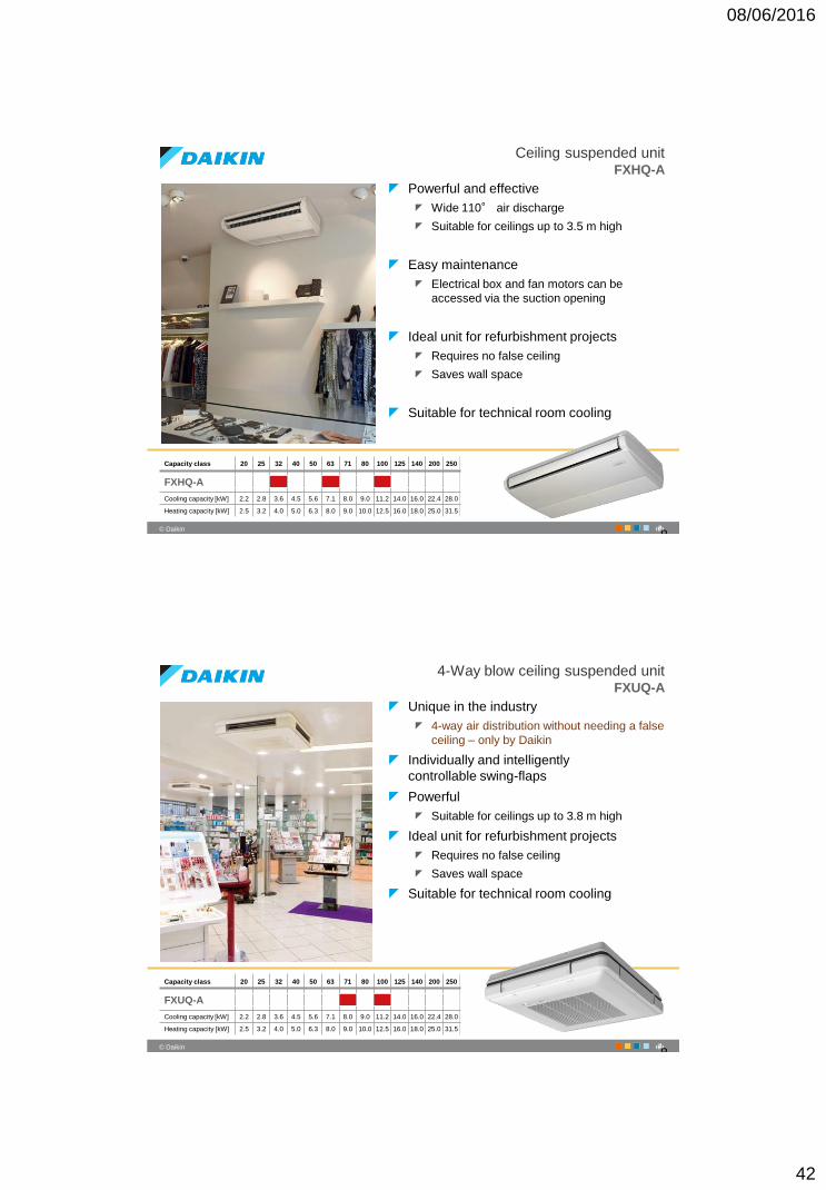
Ceiling mounted corner cassetteFXKQ-MA
Extremely slim for small ceiling spaces
Installation height of only 220 mm
Versatile application
Possibility to discharge into a duct
Can work from ceilings up to 3.8 m high
Easy service
Access to electrical box through suction
grille
Comfort and convenience functions
Ceiling soiling prevention
Draft prevention
Suitable for technical room cooling
Capacity class 20 25 32 40 50 63 71 80 100 125 140 200 250
FXKQ-MA
Cooling capacity [kW] 2.2 2.8 3.6 4.5 5.6 7.1 8.0 9.0 11.2 14.0 16.0 22.4 28.0
Heating capacity [kW] 2.5 3.2 4.0 5.0 6.3 8.0 9.0 10.0 12.5 16.0 18.0 25.0 31.5
8
08/06/2016
42
83
‹#›© Daikin
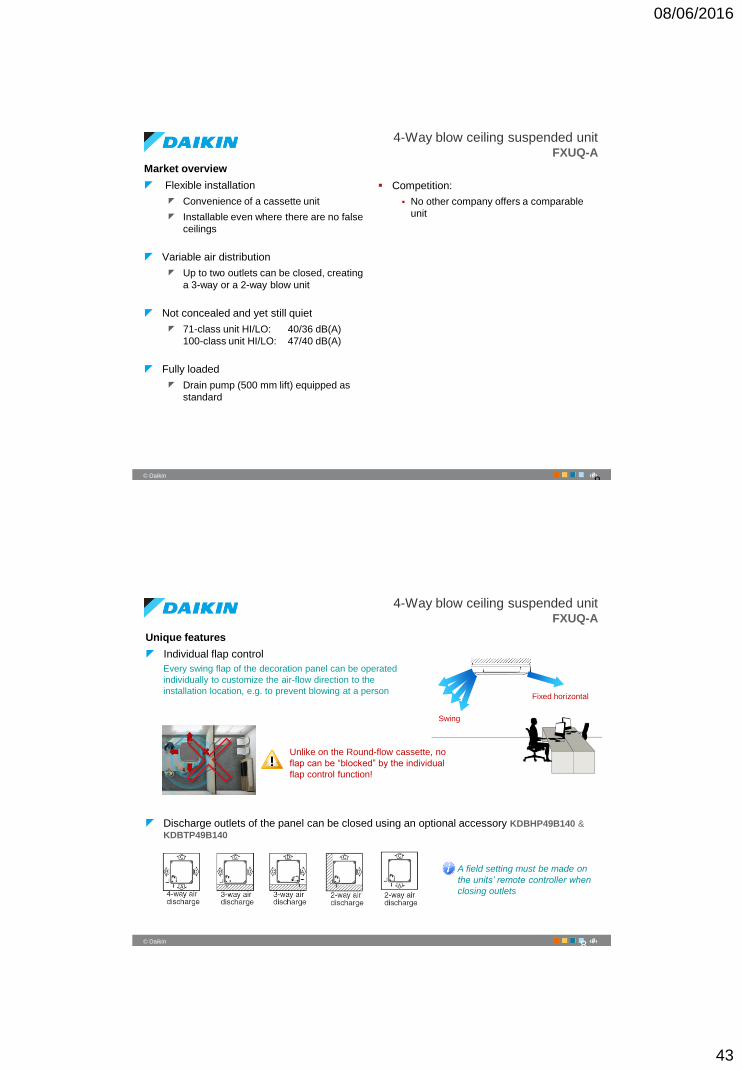
Ceiling suspended unitFXHQ-A
Powerful and effective
Wide 110° air discharge
Suitable for ceilings up to 3.5 m high
Easy maintenance
Electrical box and fan motors can be
accessed via the suction opening
Ideal unit for refurbishment projects
Requires no false ceiling
Saves wall space
Suitable for technical room cooling
Capacity class 20 25 32 40 50 63 71 80 100 125 140 200 250
FXHQ-A
Cooling capacity [kW] 2.2 2.8 3.6 4.5 5.6 7.1 8.0 9.0 11.2 14.0 16.0 22.4 28.0
Heating capacity [kW] 2.5 3.2 4.0 5.0 6.3 8.0 9.0 10.0 12.5 16.0 18.0 25.0 31.5
8
84
‹#›© Daikin
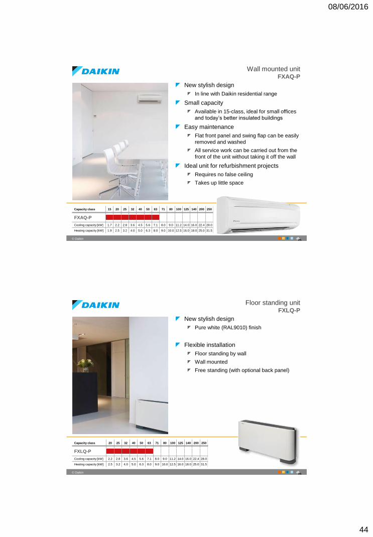
4-Way blow ceiling suspended unitFXUQ-A
Unique in the industry
4-way air distribution without needing a false
ceiling – only by Daikin
Individually and intelligently
controllable swing-flaps
Powerful
Suitable for ceilings up to 3.8 m high
Ideal unit for refurbishment projects
Requires no false ceiling
Saves wall space
Suitable for technical room cooling
Capacity class 20 25 32 40 50 63 71 80 100 125 140 200 250
FXUQ-A
Cooling capacity [kW] 2.2 2.8 3.6 4.5 5.6 7.1 8.0 9.0 11.2 14.0 16.0 22.4 28.0
Heating capacity [kW] 2.5 3.2 4.0 5.0 6.3 8.0 9.0 10.0 12.5 16.0 18.0 25.0 31.5
8
08/06/2016
43
85
‹#›© Daikin
4-Way blow ceiling suspended unitFXUQ-A
Market overview
Flexible installation
Convenience of a cassette unit
Installable even where there are no false
ceilings
Variable air distribution
Up to two outlets can be closed, creating
a 3-way or a 2-way blow unit
Not concealed and yet still quiet
71-class unit HI/LO: 40/36 dB(A)
100-class unit HI/LO: 47/40 dB(A)
Fully loaded
Drain pump (500 mm lift) equipped as
standard
Competition:
No other company offers a comparable
unit
8
86
‹#›© Daikin
4-Way blow ceiling suspended unitFXUQ-A
Unique features
Individual flap control
Every swing flap of the decoration panel can be operated
individually to customize the air-flow direction to the
installation location, e.g. to prevent blowing at a personFixed horizontal
Swing
Unlike on the Round-flow cassette, no
flap can be “blocked” by the individual
flap control function!
Discharge outlets of the panel can be closed using an optional accessory KDBHP49B140 &
KDBTP49B140
8
A field setting must be made on
the units’ remote controller when
closing outlets
08/06/2016
44
87
‹#›© Daikin
Wall mounted unitFXAQ-P
New stylish design
In line with Daikin residential range
Small capacity
Available in 15-class, ideal for small offices
and today’s better insulated buildings
Easy maintenance
Flat front panel and swing flap can be easily
removed and washed
All service work can be carried out from the
front of the unit without taking it off the wall
Ideal unit for refurbishment projects
Requires no false ceiling
Takes up little space
Capacity class 15 20 25 32 40 50 63 71 80 100 125 140 200 250
FXAQ-P
Cooling capacity [kW] 1.7 2.2 2.8 3.6 4.5 5.6 7.1 8.0 9.0 11.2 14.0 16.0 22.4 28.0
Heating capacity [kW] 1.9 2.5 3.2 4.0 5.0 6.3 8.0 9.0 10.0 12.5 16.0 18.0 25.0 31.5
8
88
‹#›© Daikin
Floor standing unitFXLQ-P
New stylish design
Pure white (RAL9010) finish
Flexible installation
Floor standing by wall
Wall mounted
Free standing (with optional back panel)
Capacity class 20 25 32 40 50 63 71 80 100 125 140 200 250
FXLQ-P
Cooling capacity [kW] 2.2 2.8 3.6 4.5 5.6 7.1 8.0 9.0 11.2 14.0 16.0 22.4 28.0
Heating capacity [kW] 2.5 3.2 4.0 5.0 6.3 8.0 9.0 10.0 12.5 16.0 18.0 25.0 31.5
8
08/06/2016
45
89
‹#›© Daikin
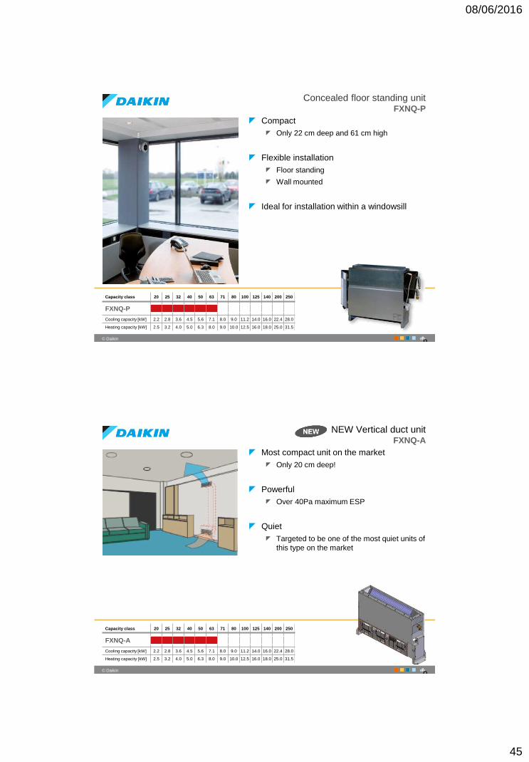
Concealed floor standing unitFXNQ-P
Compact
Only 22 cm deep and 61 cm high
Flexible installation
Floor standing
Wall mounted
Ideal for installation within a windowsill
Capacity class 20 25 32 40 50 63 71 80 100 125 140 200 250
FXNQ-P
Cooling capacity [kW] 2.2 2.8 3.6 4.5 5.6 7.1 8.0 9.0 11.2 14.0 16.0 22.4 28.0
Heating capacity [kW] 2.5 3.2 4.0 5.0 6.3 8.0 9.0 10.0 12.5 16.0 18.0 25.0 31.5
8
90
‹#›© Daikin
NEW Vertical duct unitFXNQ-A
Most compact unit on the market
Only 20 cm deep!
Powerful
Over 40Pa maximum ESP
Quiet
Targeted to be one of the most quiet units of
this type on the market
Capacity class 20 25 32 40 50 63 71 80 100 125 140 200 250
FXNQ-A
Cooling capacity [kW] 2.2 2.8 3.6 4.5 5.6 7.1 8.0 9.0 11.2 14.0 16.0 22.4 28.0
Heating capacity [kW] 2.5 3.2 4.0 5.0 6.3 8.0 9.0 10.0 12.5 16.0 18.0 25.0 31.5
9
08/06/2016
46
91
‹#›© Daikin
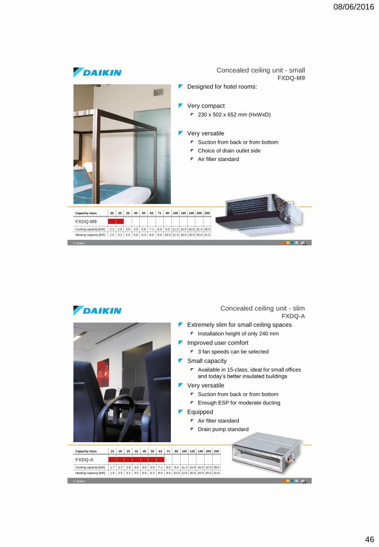
Concealed ceiling unit - smallFXDQ-M9
Designed for hotel rooms:
Very compact
230 x 502 x 652 mm (HxWxD)
Very versatile
Suction from back or from bottom
Choice of drain outlet side
Air filter standard
Capacity class 20 25 32 40 50 63 71 80 100 125 140 200 250
FXDQ-M9
Cooling capacity [kW] 2.2 2.8 3.6 4.5 5.6 7.1 8.0 9.0 11.2 14.0 16.0 22.4 28.0
Heating capacity [kW] 2.5 3.2 4.0 5.0 6.3 8.0 9.0 10.0 12.5 16.0 18.0 25.0 31.5
9
92
‹#›© Daikin
Concealed ceiling unit - slimFXDQ-A
Extremely slim for small ceiling spaces
Installation height of only 240 mm
Improved user comfort
3 fan speeds can be selected
Small capacity
Available in 15-class, ideal for small offices
and today’s better insulated buildings
Very versatile
Suction from back or from bottom
Enough ESP for moderate ducting
Equipped
Air filter standard
Drain pump standard
Capacity class 15 20 25 32 40 50 63 71 80 100 125 140 200 250
FXDQ-A
Cooling capacity [kW] 1.7 2.2 2.8 3.6 4.5 5.6 7.1 8.0 9.0 11.2 14.0 16.0 22.4 28.0
Heating capacity [kW] 1.9 2.5 3.2 4.0 5.0 6.3 8.0 9.0 10.0 12.5 16.0 18.0 25.0 31.5
9
08/06/2016
47
93
‹#›© Daikin
Concealed ceiling unit - standardFXSQ-P
Easy to install and set up
Offers the unique Automatic Airflow
Adjustment function
Over 10 fan curves can be selected
Improved user comfort
3 fan speeds can be selected
Wide capacity range
From 2.2 to 16.0 kW cooling
Very versatile
Suction from back or from bottom
Enough ESP for long ducting
Equipped
Drain pump standard
Capacity class 20 25 32 40 50 63 71 80 100 125 140 200 250
FXSQ-P
Cooling capacity [kW] 2.2 2.8 3.6 4.5 5.6 7.1 8.0 9.0 11.2 14.0 16.0 22.4 28.0
Heating capacity [kW] 2.5 3.2 4.0 5.0 6.3 8.0 9.0 10.0 12.5 16.0 18.0 25.0 31.5
9
94
‹#›© Daikin
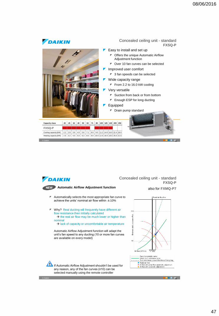
Automatic Airflow Adjustment function
Automatically selects the most appropriate fan curve to
achieve the units’ nominal air flow within ±10%
Why? Real ducting will frequently have different air
flow resistance then initially calculated
the real air flow may be much lower or higher than
nominal
lack of capacity or uncomfortable air temperature
Automatic Airflow Adjustment function will adapt the
unit’s fan speed to any ducting (10 or more fan curves
are available on every model)
If Automatic Airflow Adjustment shouldn’t be used for
any reason, any of the fan curves (≥10) can be
selected manually using the remote controller
Concealed ceiling unit - standardFXSQ-P
also for FXMQ-P7
9
08/06/2016
48
95
‹#›© Daikin
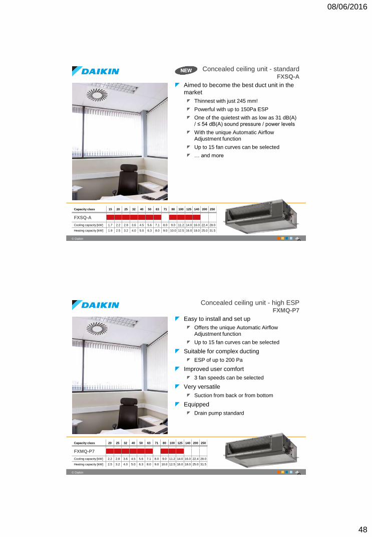
Concealed ceiling unit - standard FXSQ-A
Aimed to become the best duct unit in the
market
Thinnest with just 245 mm!
Powerful with up to 150Pa ESP
One of the quietest with as low as 31 dB(A)
/ ≤ 54 dB(A) sound pressure / power levels
With the unique Automatic Airflow
Adjustment function
Up to 15 fan curves can be selected
… and more
9
Capacity class 15 20 25 32 40 50 63 71 80 100 125 140 200 250
FXSQ-A
Cooling capacity [kW] 1.7 2.2 2.8 3.6 4.5 5.6 7.1 8.0 9.0 11.2 14.0 16.0 22.4 28.0
Heating capacity [kW] 1.9 2.5 3.2 4.0 5.0 6.3 8.0 9.0 10.0 12.5 16.0 18.0 25.0 31.5
96
‹#›© Daikin
Concealed ceiling unit - high ESPFXMQ-P7
Easy to install and set up
Offers the unique Automatic Airflow
Adjustment function
Up to 15 fan curves can be selected
Suitable for complex ducting
ESP of up to 200 Pa
Improved user comfort
3 fan speeds can be selected
Very versatile
Suction from back or from bottom
Equipped
Drain pump standard
Capacity class 20 25 32 40 50 63 71 80 100 125 140 200 250
FXMQ-P7
Cooling capacity [kW] 2.2 2.8 3.6 4.5 5.6 7.1 8.0 9.0 11.2 14.0 16.0 22.4 28.0
Heating capacity [kW] 2.5 3.2 4.0 5.0 6.3 8.0 9.0 10.0 12.5 16.0 18.0 25.0 31.5
9
08/06/2016
49
97
‹#›© Daikin
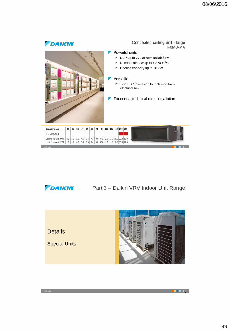
Concealed ceiling unit - largeFXMQ-MA
Powerful units
ESP up to 270 at nominal air flow
Nominal air flow up to 4.320 m3/h
Cooling capacity up to 28 kW
Versatile
Two ESP levels can be selected from
electrical box
For central technical room installation
Capacity class 20 25 32 40 50 63 71 80 100 125 140 200 250
FXMQ-MA
Cooling capacity [kW] 2.2 2.8 3.6 4.5 5.6 7.1 8.0 9.0 11.2 14.0 16.0 22.4 28.0
Heating capacity [kW] 2.5 3.2 4.0 5.0 6.3 8.0 9.0 10.0 12.5 16.0 18.0 25.0 31.5
9
98
‹#›© Daikin
Part 3 – Daikin VRV Indoor Unit Range
Details
Special Units
9
08/06/2016
50
99
‹#›© Daikin
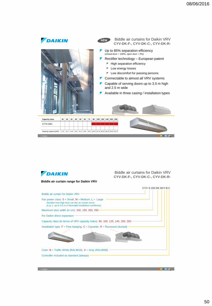
Biddle air curtains for Daikin VRVCYV-DK-F-, CYV-DK-C-, CYV-DK-R-
Up to 85% separation efficiency(closed door = 100%, open door = 0%)
Rectifier technology – European patent
High separation efficiency
Low energy losses
Low discomfort for passing persons
Connectable to almost all VRV systems
Capable of serving doors up to 3.0 m high
and 2.5 m wide
Available in three casing / installation types
Capacity class 20 25 32 40 50 63 71 80 100 125 140 200 250
CYV-DK-
Heating capacity [kW] 2.5 3.2 4.0 5.0 6.3 8.0 9.0 10.0 12.5 16.0 18.0 25.0 31.5
9
100
‹#›© Daikin
Biddle air curtains for Daikin VRVCYV-DK-F-, CYV-DK-C-, CYV-DK-R-
Biddle air curtain range for Daikin VRV
CYV S 150 DK 80 F B C
Biddle air curtain for Daikin VRV
Fan power class: S = Small, M = Medium, L = Large
Decides how high door can the air curtain serve
(e.g. L: up to 3.0 m in favorable installation conditions)
Maximum door width (in cm): 100, 150, 200, 250
For Daikin direct expansion
Capacity class (in terms of VRV capacity index): 80, 100, 125, 140, 200, 250
Installation type: F = Free hanging, C = Cassette, R = Recessed (ducted)
Color: B = Traffic White (RAL9016), S = Grey (RAL9006)
Controller included as standard (always)
1
08/06/2016
51
101
‹#›© Daikin
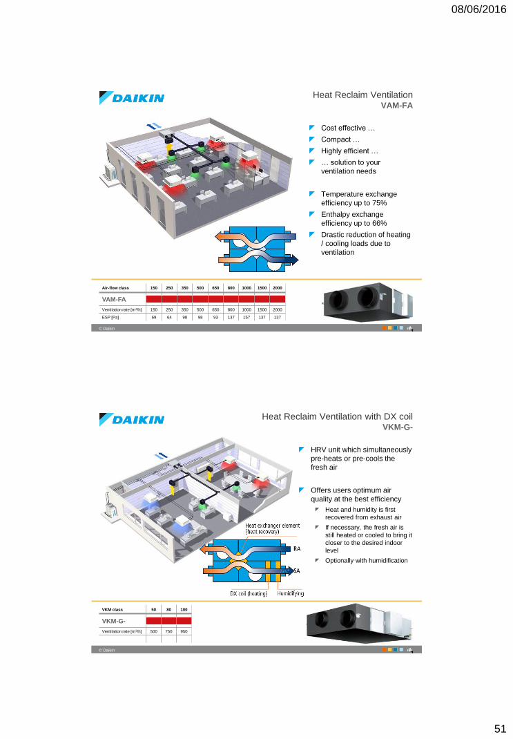
Heat Reclaim VentilationVAM-FA
Cost effective …
Compact …
Highly efficient …
… solution to your
ventilation needs
Temperature exchange
efficiency up to 75%
Enthalpy exchange
efficiency up to 66%
Drastic reduction of heating
/ cooling loads due to
ventilation
Air-flow class 150 250 350 500 650 800 1000 1500 2000
VAM-FA
Ventilation rate [m3/h] 150 250 350 500 650 800 1000 1500 2000
ESP [Pa] 69 64 98 98 93 137 157 137 137
1
102
‹#›© Daikin
Heat Reclaim Ventilation with DX coil VKM-G-
HRV unit which simultaneously
pre-heats or pre-cools the
fresh air
Offers users optimum air
quality at the best efficiency
Heat and humidity is first
recovered from exhaust air
If necessary, the fresh air is
still heated or cooled to bring it
closer to the desired indoor
level
Optionally with humidification
VKM class 50 80 100
VKM-G-
Ventilation rate [m3/h] 500 750 950
1
08/06/2016
52
103
‹#›© Daikin
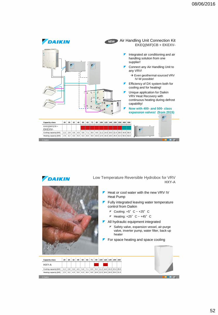
Air Handling Unit Connection Kit EKEQ(M/F)CB + EKEXV-
Integrated air conditioning and air
handling solution from one
supplier!
Connect any Air Handling Unit to
any VRV!
Even geothermal-sourced VRV
IV-W possible!
Efficiency of DX system both for
cooling and for heating!
Unique application for Daikin
VRV Heat Recovery with
continuous heating during defrost
capability!
Now with 400- and 500- class
expansion valves! (from 2015)
Capacity class 20 25 32 40 50 63 71 80 100 125 140 200 250 400 500
EKEQ(M/F)CB +
EKEXV-Cooling capacity [kW] 2.2 2.8 3.6 4.5 5.6 7.1 8.0 9.0 11.2 14.0 16.0 22.4 28.0 44.8 56.0
Heating capacity [kW] 2.5 3.2 4.0 5.0 6.3 8.0 9.0 10.0 12.5 16.0 18.0 25.0 31.5 50.0 63.0
1
104
‹#›© Daikin
Low Temperature Reversible Hydrobox for VRVHXY-A
Heat or cool water with the new VRV IV
Heat Pump
Fully integrated leaving water temperature
control from Daikin
Cooling: +5°C ~ +25°C
Heating: +25°C ~ +45°C
All hydraulic equipment integrated
Safety valve, expansion vessel, air-purge
valve, inverter pump, water filter, back-up
heater
For space heating and space cooling
Capacity class 20 25 32 40 50 63 71 80 100 125 140 200 250
HXY-A
Cooling capacity [kW] 2.2 2.8 3.6 4.5 5.6 7.1 8.0 9.0 11.2 14.0 16.0 22.4 28.0
Heating capacity [kW] 2.5 3.2 4.0 5.0 6.3 8.0 9.0 10.0 12.5 16.0 18.0 25.0 31.5
1
08/06/2016
53
105
‹#›© Daikin
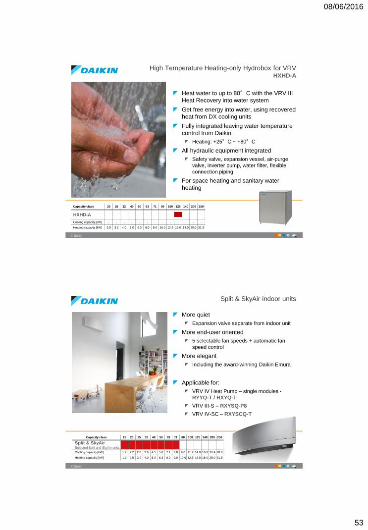
High Temperature Heating-only Hydrobox for VRVHXHD-A
Heat water to up to 80°C with the VRV III
Heat Recovery into water system
Get free energy into water, using recovered
heat from DX cooling units
Fully integrated leaving water temperature
control from Daikin
Heating: +25°C ~ +80°C
All hydraulic equipment integrated
Safety valve, expansion vessel, air-purge
valve, inverter pump, water filter, flexible
connection piping
For space heating and sanitary water
heating
Capacity class 20 25 32 40 50 63 71 80 100 125 140 200 250
HXHD-A
Cooling capacity [kW] - - - - - - - - - - - - -
Heating capacity [kW] 2.5 3.2 4.0 5.0 6.3 8.0 9.0 10.0 12.5 16.0 18.0 25.0 31.5
1
106
‹#›© Daikin
Split & SkyAir indoor units
More quiet
Expansion valve separate from indoor unit
More end-user oriented
5 selectable fan speeds + automatic fan
speed control
More elegant
Including the award-winning Daikin Emura
Applicable for:
VRV IV Heat Pump – single modules -
RYYQ-T / RXYQ-T
VRV III-S – RXYSQ-P8
VRV IV-SC – RXYSCQ-T
Capacity class 15 20 25 32 40 50 63 71 80 100 125 140 200 250
Split & SkyAir Selected Split and SkyAir units
Cooling capacity [kW] 1.7 2.2 2.8 3.6 4.5 5.6 7.1 8.0 9.0 11.2 14.0 16.0 22.4 28.0
Heating capacity [kW] 1.9 2.5 3.2 4.0 5.0 6.3 8.0 9.0 10.0 12.5 16.0 18.0 25.0 31.5
1
08/06/2016
54
107
‹#›© Daikin
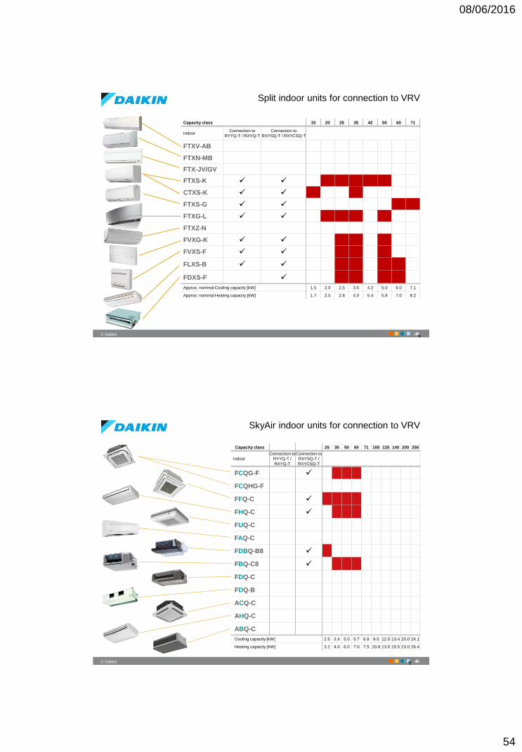
Split indoor units for connection to VRV
1
Capacity class 15 20 25 35 42 50 60 71
IndoorConnection to
RYYQ-T / RXYQ-T
Connection to
RXYSQ-T / RXYCSQ-T
FTXV-AB
FTXN-MB
FTX-JV/GV
FTXS-K
CTXS-K
FTXS-G
FTXG-L
FTXZ-N
FVXG-K
FVXS-F
FLXS-B
FDXS-F
Approx. nominal Cooling capacity [kW] 1.5 2.0 2.5 3.5 4.2 5.0 6.0 7.1
Approx. nominal Heating capacity [kW] 1.7 2.5 2.8 4.0 5.4 5.8 7.0 8.2
108
‹#›© Daikin
SkyAir indoor units for connection to VRV
1
Capacity class 25 35 50 60 71 100 125 140 200 250
Indoor
Connection to
RYYQ-T /
RXYQ-T
Connection to
RXYSQ-T /
RXYCSQ-T
FCQG-F
FCQHG-F
FFQ-C
FHQ-C
FUQ-C
FAQ-C
FDBQ-B8
FBQ-C8
FDQ-C
FDQ-B
ACQ-C
AHQ-C
ABQ-C
Cooling capacity [kW] 2.5 3.4 5.0 5.7 6.8 9.5 12.0 13.4 20.0 24.1
Heating capacity [kW] 3.2 4.0 6.0 7.0 7.5 10.8 13.5 15.5 23.0 26.4

08/06/2016
55
TOP SECRET
SECRET
INTERNAL USE ONLY
PUBLIC
THANK YOU


