


Determination of in situ water permeability of
bituminous road surfacing or base coarse layers by
using the falling head (Marvil) apparatus. (Test
Method: COLTO 8109 (d))

• Scope
• Apparatus
• Test procedure
• Factors influencing permeability of
layer
• Problems encountered and possible
solutions
ContentsContentsContentsContents

ScopeScopeScopeScope
This method describes the determination of the in situ
water permeability of asphalt surfacing and/or base
course layers and is based on the principle of the falling
head permeameter. The permeability of a layer is an
indication of the intensity of interconnected voids in the
layer which may be detrimental to the material due to
oxidation of the binder and/or ingress of water to the
lower layers.

ApparatusApparatusApparatusApparatus
The apparatus consists of the falling head permeability
(Marvil) apparatus with a circular weight and an acrylic
tube with volume markings from 0ml to 300ml in 50ml
increments.

Test ProcedureTest ProcedureTest ProcedureTest Procedure
A test point is randomly selected. Using a brush clean the test area
from all loose dust and aggregate. Seal the base of the Marvil
apparatus with Prestik and grease and place on the selected test area.
Fill the apparatus from the top in the shortest time possible. Fill the
water to the 0ml mark or just above it if the layer is very permeable.
Record the time it takes the water level to drop to one of the graduated
marks.

Test ProceduresTest ProceduresTest ProceduresTest Procedures
The permeability is then calculated using this data and the following formula:
P = 3,6 Vw / Tsec
Where: P = Permeability in Liter/h (Correct to nearest 0,1)
Vw = Volume of water in ml between the 0 mark and selected volume mark.
Tsec = Time in seconds taken by the water to drop from the zero mark to the selected volume mark.

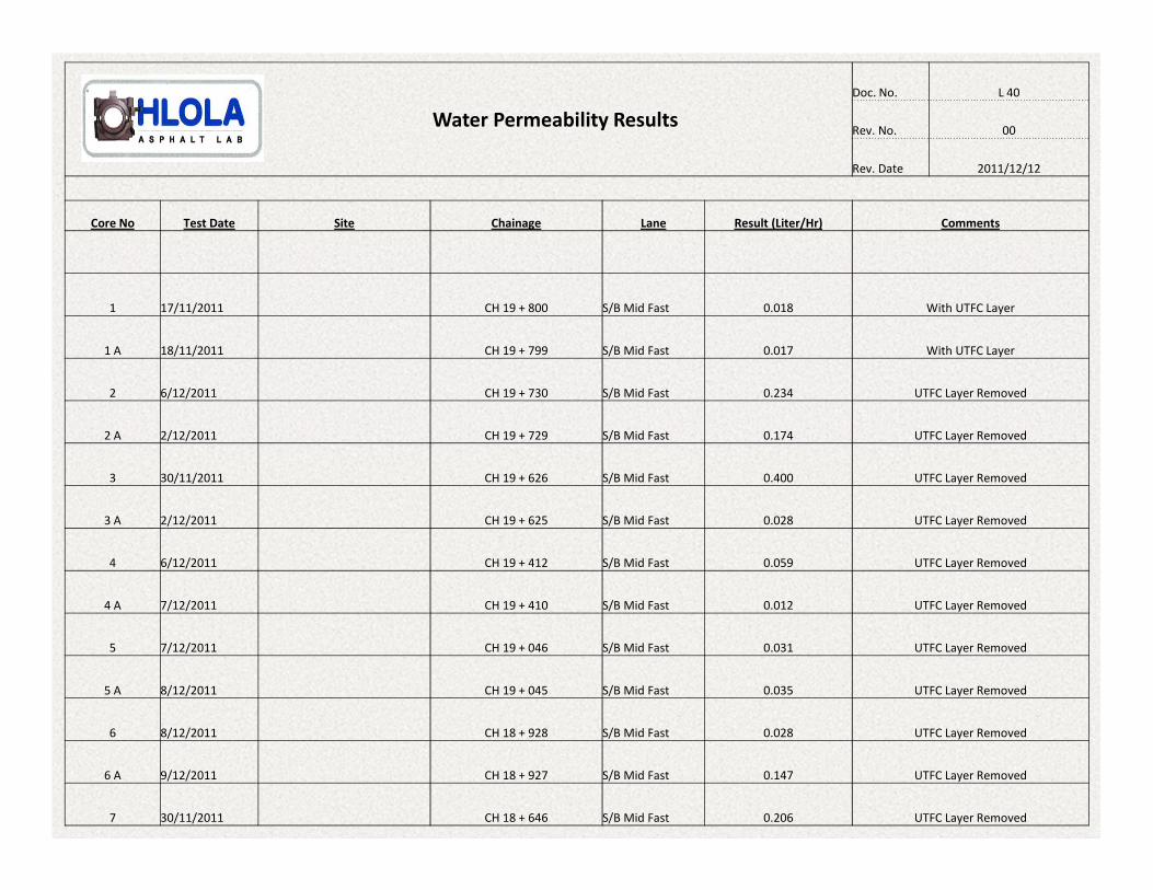
Water Permeability Results
Doc. No. L 40
Rev. No. 00
Rev. Date 2011/12/12
Core No Test Date Site Chainage Lane Result (Liter/Hr) Comments
1 17/11/2011 CH 19 + 800 S/B Mid Fast 0.018 With UTFC Layer
1 A 18/11/2011 CH 19 + 799 S/B Mid Fast 0.017 With UTFC Layer
2 6/12/2011 CH 19 + 730 S/B Mid Fast 0.234 UTFC Layer Removed
2 A 2/12/2011 CH 19 + 729 S/B Mid Fast 0.174 UTFC Layer Removed
3 30/11/2011 CH 19 + 626 S/B Mid Fast 0.400 UTFC Layer Removed
3 A 2/12/2011 CH 19 + 625 S/B Mid Fast 0.028 UTFC Layer Removed
4 6/12/2011 CH 19 + 412 S/B Mid Fast 0.059 UTFC Layer Removed
4 A 7/12/2011 CH 19 + 410 S/B Mid Fast 0.012 UTFC Layer Removed
5 7/12/2011 CH 19 + 046 S/B Mid Fast 0.031 UTFC Layer Removed
5 A 8/12/2011 CH 19 + 045 S/B Mid Fast 0.035 UTFC Layer Removed
6 8/12/2011 CH 18 + 928 S/B Mid Fast 0.028 UTFC Layer Removed
6 A 9/12/2011 CH 18 + 927 S/B Mid Fast 0.147 UTFC Layer Removed
7 30/11/2011 CH 18 + 646 S/B Mid Fast 0.206 UTFC Layer Removed

• The degree of saturation of the layer, eg. After a spell of rain or
due to built-in moisture content.
• The degree of density of the layer.
• The grading, shape and texture of the material used in the layer.
• The degree of saturation of the underlying layer under a thin
upper layer.
• Testing of the surface where it shows signs of intensive cracking
should be considered.
Factors influencing Factors influencing Factors influencing Factors influencing
Permeability of a layerPermeability of a layerPermeability of a layerPermeability of a layer

Problems encountered and
possible solutions
• Problem
Improper seal between apparatus and road surface.
• Solutions
Seal apparatus onto surface with silicone.
Cut core from road and test.


