

STUDIO AIR JOURNAL2014, SEMESTER 2, PHILSARAH WARING

COVER IMAGE:PAUL MCCOLLAM, ‘HILLY’, IMAGE, STRUCTURAL SURFACE, <HTTP://PAULMCCOLLAM.COM/WP-CONTENT/UPLOADS/
HILLY.JPG> [ACCESSED 4 AUGUST 2014].

Table of Contents
4 Introduction
7 PART A: CONCEPTUALISATION
8 A.1. Design Futuring
12 A.2. Design Computation
19 A.3. Compositional and Generative Strategies
33 A.4. Conclusion
34 A.5. Learning Outcomes
35 A.6. Appendix: Algorithmic Sketches
36 Part A Reference List
37 Part A Image Reference List
41 PART B: CRITERIA DESIGN
42 B.1. Research Field: Geometry
48 B.2. Case Study 1.0: BanQ
60 B.3. Case Study 2.0: Swiss Re HQ
68 B.4. Technique Development with Case Study 2.0
72 B.5. Technique: Prototype
78 B.6. Technique: Proposal
90 B.7. Learning Objectives and Outcomes
91 Part B Reference List
92 Part B Image List
94 B.8. Appendix: Algorithmic Sketches
96 PART C: DETAILED DESIGN
98 C.1. Design Concept
125 C.2. Tectonic Elements & Prototypes
142 C.3. Final Detail Model
150 C.4. Learning Objectives & Outcomes
156 Part C Bibliography
156 Part C Image List

4 CONCEPTUALISATION
My name is Sarah Waring. I am currently an
undergraduate student in my last year of the Bachelor
of Environments at The University of Melbourne,
majoring in Architecture, though this was not always
the case. I had commenced my tertiary education with
the Bachelor of Science at The University of Melbourne
and transferred to Environments at the end of my first
year after taking Designing Environments. I had been,
and still am, relatively unsure of what I want career I
wanted to pursue, conflicted by an admiration for the
methodical, technical and defined realm of science as
well as the ephemeral and transcendental world of art.
It was at the crossroads of these fields that I found
architecture, or rather it found me, with its embrace of
the artistic as well as the methodological and technical.
I was always drawn to design and have had a love and
propensity for it since my childhood. I spent alot of my
time playing with Lego, constructing cities in Sims, and
making robots, houses and contraptions out of cardboard,
masking tape and anything else at my disposal.
Having moved between Australia and California a few
times I have had the opportunity to travel to many places
ranging from New York to Tanzania, Rome, and Hong
Kong, which allowed me to experience first hand various
international approaches to architecture and design.
As I have only recently ventured into the world of
architecture, I have had just a little bit of experience
with technical drawing and computer rendering
technologies. I was briefly introduced to Rhino during
a workshop for my Visual Communications class,
and supplemented this with additional self-teaching
to produce my final project for Architectural Design
Studio Earth (Fig. 1). Even with my preliminary technical
skills I was proud to be able to visually represent my
ideas and design in a clear and interesting manner.
Introduction

CONCEPTUALISATION 5
FIG.1: RHINO MODEL OF DESIGN OF FINAL PROJECT FOR DESIGN STUDIO EARTH

6 CONCEPTUALISATION

CONCEPTUALISATION 7
PART A: CONCEPTUALISATION

8 CONCEPTUALISATION
Design is the ‘front-line of transformative action” [1]
in the battle for possible futures. Design Futuring is
about changing the way that we design and think about
design, so that we can move from our current path of
unsustainability, in which we are sacrificing ‘the future
to sustain the excess of the present’[2], to follow the
Sustainment movement. This entails individuals thinking
about how their lives influence the world we live in and
the cost and impact of their actions. It requires not
only a reshaping of design to be more sustainable, but
the redirection of peoples lives to a more sustainable,
environmentally conscientious and enlightened path.
Through design individuals are both encouraged and
enabled to live more sustainable lives. The utlimate
goal being to design the possibility of futures not
destroyed by our current consumption and devastation.
After all, ‘we only have a future by design’ [3].
This movement of design futuring entails designing
not only to have a minimal impact on the environment
in terms of ecological footprint and embodied energy
of a design, but also to invigorate a consciousness
in the individual for a more sustainable mindset
and lifestyle. Design Futuring has two tasks. Firstly
to reduce the rate with which we are ‘defuturing’
with our unsustainable designs and lifestyles, and
secondly, to redirect our ideas of habitation to
embrace design[4] ‘as a world-shaping force’ [5].
The Land Art Generator Initiative (LAGI) aims to
encourage design futuring through its competitions
for designs of land art installations that are a
combination of aesthetics and practical concepts
which include the generation of clean green
energy to be contributed to a city’s grid [6].
A.1. Design Futuring
Photoreactor Farm Tower
2010 LAGI SUBMISSIONTEAM: GREGOIRE DIEHL, XUHUI LIU, ALEXANDRE
BRALERET, LEA SANTAMARIAThis team of French designers attempted design
futuring with their photoreactor farm tower which
harnesses the potential of algal greenhouses to produce
clean, renewable energy that could be collected and
transported to the grid. This was incorporated into
their design in the form of their artistic installation of
vertical green algal glass tubes, which creates an algal
greenhouse that produces energy. Though this alternative
energy source is not a radical new idea, it is unusually
incorporated as part of an artistic instalment that
minimizes the amount of land cover with its verticality.
The use of this renewable energy source as part of a
piece of land art encourages users to interact with it
and consequently encourages positive perceptions
of design futuring and of alternate energy sources. It
posits the real possibility of living a more sustainable
lifestyle without sacrificing aesthetics and arts.
This entry has a number of faults though. The objective
put forth by LAGI was to put the aim of creating a
land art installation first and foremost, rather than
developing an institution to research energy sources.
The tower, a vertical stack of environmentally focused
functions, dominates the design and overpowers the
impact of the surrounding glass tube installation.
Additionally, the embodied energy required to construct
such a tower would not only likely negate the energy
produced by the algal tubes, but the land area saved by
extending the building vertically rather than spreading
it horizontally is used by the green algal tubes.
1. Tony Fry, Design Futuring: Sustainability, Ethics and New Practice (Oxford: Berg, 2009), pp. 6.
2. Tony, Design Futuring, pp.2.
3. Tony, Design Futuring, pp.3
4. Tony, Design Futuring, pp.6.
5. Tony, Design Futuring, pp.3.
6. Robert Ferry and Elizabeth Monoian ‘Design Guidelines: Land Art Generator Initiative’, Land Art Generator Initiative, Copenhagen <http://landartgenerator.org/images/LAGI2010DESIGNGUIDELINES.pdf> [accessed 1 August 2014].
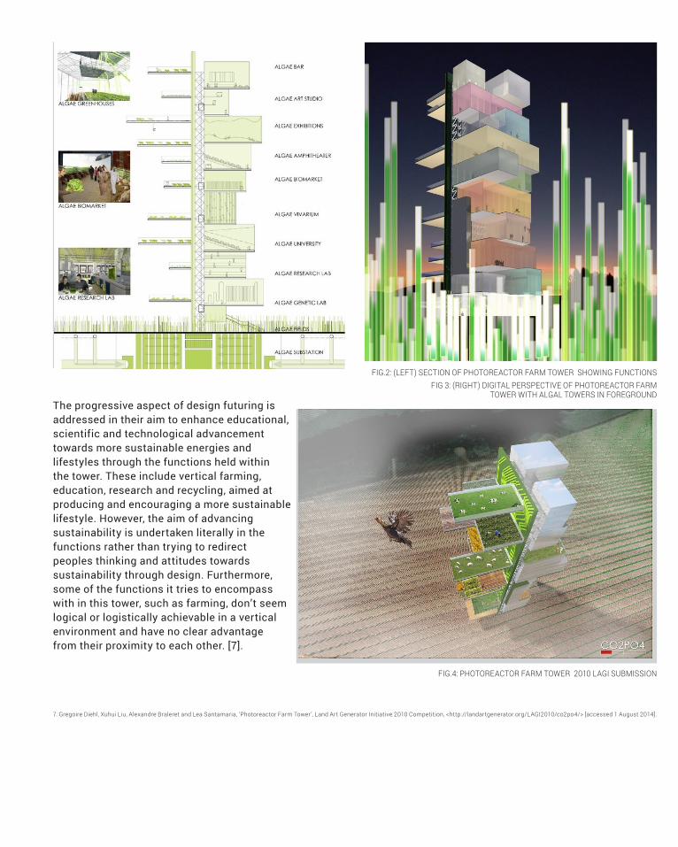
The progressive aspect of design futuring is
addressed in their aim to enhance educational,
scientific and technological advancement
towards more sustainable energies and
lifestyles through the functions held within
the tower. These include vertical farming,
education, research and recycling, aimed at
producing and encouraging a more sustainable
lifestyle. However, the aim of advancing
sustainability is undertaken literally in the
functions rather than trying to redirect
peoples thinking and attitudes towards
sustainability through design. Furthermore,
some of the functions it tries to encompass
with in this tower, such as farming, don’t seem
logical or logistically achievable in a vertical
environment and have no clear advantage
from their proximity to each other. [7].
FIG.4: PHOTOREACTOR FARM TOWER 2010 LAGI SUBMISSION
7. Gregoire Diehl, Xuhui Liu, Alexandre Braleret and Lea Santamaria, ‘Photoreactor Farm Tower’, Land Art Generator Initiative 2010 Competition, <http://landartgenerator.org/LAGI2010/co2po4/> [accessed 1 August 2014].
FIG.2: (LEFT) SECTION OF PHOTOREACTOR FARM TOWER SHOWING FUNCTIONSFIG 3: (RIGHT) DIGITAL PERSPECTIVE OF PHOTOREACTOR FARM
TOWER WITH ALGAL TOWERS IN FOREGROUND

10 CONCEPTUALISATION
the user to find a connection between this man-
made design and the environment thus encouraging
them to consider the impact of their actions.
By elevating the ribbons off the ground, minimizing the
contact with the terrain, this sculptural, artistic design
that generates energy, encourages ideas of minimizing
ones impact upon the planet. It promotes the idea to
not only literally reduce one’s carbon footprint and the
amount of natural landscape destroyed to make way for
modern life, but to mitigate this effect by positing that
one doesn’t need to give up modern aspirations and
lifestyle in order to preserve and mend the environment.
The design of the Light Sanctuary is not only stronger
and more realistically possible to construct, but it also
effectively addresses the competitions guidelines. First
and foremost, it is a landscape artwork and secondly
it practically functions as a means of generating and
collecting energy that can be transferred to the grid [8].
Like the algal tower, this submission focused on
minimizing the degree to which the design interacts
with the ground, taking advantage of the vertical
dimension, and used an unusual energy sources. The
Light Sanctuary land-art is composed of a network of
ribbons made of thin solar membranes that generate
and capture solar energy and transfer it to the grid
(Fig. 5).The amount of energy captured by the design is
optimized not only by the large surface area of the solar
membranes that make up the ribbons, but also by the
revolutionary technology that allows for the absorption of
light even when vertical, thus maximizing the amount of
penetration while minimizing the amount of land covered.
The maze-like pattern of the design through which
the user transverses, echoes the characteristics
of the site in its colouring and the contours of the
topography. The interaction with the structure prompts
FIG.5 LIGHT SANCTUARY 2010 LAGI SUBMISSIONLight Sanctuary: An empowered landscape for the UAE
2010 LAGI SUBMISSIONTEAM: MARTINA DECKER AND PETER YEADON
8. Martina Decker and Peter Yeadon, ‘Light Sanctuary: An empowered landscape for the UAE’, Land Art Generator Initiative 2010 Competition <http://landartgenerator.org/LAGI2010/8s3b9u/> [accessed 2 August 2014].

CONCEPTUALISATION 11
FIG.6 LIGHT SANCTUARY 2010 LAGI SUBMISSION
FIG.7 GROUND LEVEL VIEW OF ELEVATED SOLAR RIBBONS OF LIGHT SANCTUARY 2010 LAGI SUBMISSION

12 CONCEPTUALISATION
A.2. Design ComputationAs design, ‘the epitome of intelligent behaviour’ [9],
has shifted from drawing to algorithmic thinking,
some worry it has been compromised and limited by
the overly enthusiastic embrace of computers in the
design process. While their concern that the reliance
of computer technologies in producing architecture
constrains this intelligence and limits the forms and
geometries produced to those achievable with the
software, is somewhat true for novice designs using
readily available popular software, it isn’t necessarily
the case for designs produced by Computerization
and Computation in architectural practice.
Computerization v. Computation
Computerization, the dominant form of contemporary
computer utilized architecture, is when an architects
pre-conceptualised designs are manipulated, stored
or input into a computer system. In other words,
the computer is used to recreate something that
was previously made without a computer by using
Computer-Aided Design (CAD) or Computer-Aided
Manufacturing (CAM ). [10] For example, software like
AutoCAD is a computerization of line-based drawings.
On the other hand, Computation, otherwise known
as computing, is the use of a computer based
design tool in which the computer figures out things
for you using algorithms in parametric modelling
software like Grasshopper. Computational design,
or ‘computing’ is an extension of computerization,
where the computer goes beyond being used
as a tool, to become a platform for design.
Computation is often utilized as a means of more
efficiently performing time consuming and repetitive
tasks by following a set of given instructions. While
the computer will faultlessly follow these instructions,
they are unable to create their own instructions. These
algorithmic instructions are the product of the creative
human mind that produced the design. Computation is
predicated on communication of shared knowledge in
the form of a set of instructions, between the computer
and the designer. This is achieved by the designer
thinking algorithmically, in other words, understanding,
executing, creating and evaluating the algorithms to be
read by the computer. It is computation, that despite
its ability to free and embrace a designers imagination,
that is accused of limiting their creativity [11] . This
is not the case however, as computation entails the
computer following a designers predetermined set of
instructions or algorithms and according to an already
conceptualized design. “Computational thinking
is the thought processes involved in formulating
problems and their solutions so that the solutions are
represented in a form that can be effectively carried
out by an information-processing agent.” [12]
Evolution of Digital Design
This realm of digital architecture that has erupted over
the last decade formed a continuum of architectural
theories that integrated architecture with science
and technology. Digital architecture was a revision
of the representational mode of form generation, and
gave rise to a period of experimental architecture that
explored otherwise impossible geometries of free-form
and the complex geometries of folds and curves[14].
Frank Gehry’s Guggenheim was one of the earliest
buildings to embrace digital architecture, and capture
its ‘fluid logic of connectivity’ [15]. Their curvilinear
surfaces and volumes were achieved by Gehry’s use
FIG.8: FRANK GEHRY’S SKETCH FOR GUGGENHEIM MUSEUM (ABOVE)FIG.9 CLOSE UP OF CURVILINEAR SURFACE OF GUGGENHEIM MUSEUM (RIGHT)
9. Yehuda E. Kalay,, Architecture’s New Media: Principles, Theories, and Methods of Computer-Aided Design (Cambridge, MA: MIT Press, 2004), pp. 1.
10. Branko Kolarevic, Architecture in the Digital Age: Design and Manufacturing (New York; London: Spon Press, 2003), pp. 31.
11. Kostas Terzidis, Algorithms for Visual Design Using the Processing Language (Indianapolis, IN: Wiley, 2009), p. xx
12. Jan Cuny, Larry Snyder, and Jeannette M. Wing, “Demystifying Computational Thinking for Non-Computer Scientists,” work in progress, 2010.
13. John Hamilton Frazer, “The Generation of Virtual Prototypes for Perforamnce Optimization”, in Oosterhuis, K., and L. Feiress (eds.), GameSetAndMatchII: The Architecture Co-Laboratory on computer Games, Advanced Geometries and Digital Technoologies, (Rotterdam: Episode publisher, 2006), pp. 208-212.
14. Rivka Oxman and Robert Oxman, eds. Theories of the Digital in Architecture (London; New York: Routledge, 2014), pp. 1.
15. Greg Lynn, eds., ‘Folding in Architecture, Architectural Design’ (Wiley-Academy: West Sussex, UK, 1993), in Oxman Rivka and Robert Oxman, eds (2014). Theories of the Digital in Architecture (London; New York: Routledge), pp. 2.

CONCEPTUALISATION 13

of computation to translate his physical model and design into a mathematically and physically achievable form. In
doing so, Gehry was able to embrace biomorphic forms that were previously essentially lost geometries due to the
difficulties in representing them architecturally, with his form reminiscent of the Expressionist artists of the 1920. [16]
Gehry’s designs were conceived prior to being transferred to a computer, which was then used as a tool
to materialize his work for construction, not for the development of the architectural design and concept.
Computation freed Gehry from traditional design constraints to achieve the artistic expression of his design
by breaking it down into mathematical realities. Digital technologies weren’t used as a medium for developing
the architectural design and concept, but were rather used as a way of translating the geometry of the design
of his physical model to produce a digital representation of its geometry by generating NURBS curves, that
could be constructed. It would be near impossible to effectively communicate and structurally conceive of this
design of curvilinear surfaces using traditional drawing techniques. Gehry’s process of reverse engineering
is the inverse of computer-aided manufacturing as it translates a physical model into a digital form. [17]
14 CONCEPTUALISATION
FIG.10: THE GUGGENHEIM MUSEUM BY FRANK GEHRY
16. Branko Kolarevic, Architecture in the Digital Age: Design and Manufacturing (New York; London: Spon Press, 2003), pp. 31.
17. Kolarevic, Architecture in the Digital Age, pp. 31.

FIG.11: THE PRODUCTION OF THE GUGGENHEIM MUSEUM FROM DIGITAL POINTS TO A DIGITAL SURFACE
Parametric design thinking follows a logic of ‘associative
and dependency relationships between objects and
their parts-and-whole relationships’ in which altering
the values of the parameters within such a geometric
relationships creates a multitude of variable results
[18]. The popularity of parametric design rose from
its ability to control the relationships that enable
the ‘creation and modulation of the differentiation of
the elements of a design” [19]. This allowed for the
emerging younger generation who were moving away
from compositional and representational theories
and embracing algorithmic scripting, to undertake
research by experimental design. [20] This experimental
design used form generating modellers, to produce
a topological geometry of curvilinear surfaces which
is prevalent in contemporary architectural design. The
appeal of these NURBS curves and surfaces is due
to the ease in which one can control their form by the
manipulation of their control points, knots and weights.
NURBS not only allows the “heterogeneous, yet coherent,
forms of the digital architectures to be computationally
possible”, that would otherwise not be conceivable
or at least extremely tedious done by hand, but their
construction is also made attainable through the use of
computer numerically controlled (CNC) machines.[21]
Benefits of Computation and computational thinking in practice
Through algorithms, computer aided design systems
assist the designer by undertaking small to large jobs
in the design process. The role that computation takes
ranges from a limited assistance drawing lines and
geometries for drafting and modelling systems, to the
evaluation of a designers solutions regarding energy,
acoustics, cost etc.., in analytical systems, to even
proposing such solutions in intelligent design systems.
EFFICIENCY
In short, computational thinking enables the
bending of computation to facilitate the designer’s
needs by being able to perform repetitive and
menial task instructed through an algorithm,
understanding and working according to a materials
constraints and can develop variations in the
design according to a set of defined parameter
PERFORMANCE ORIENTED DESIGN
In conjunction with the emergence of a new generation
of digital architecture, came the embrace of integrated
simulation software that enabled the calculation
of the performance of a building in terms of its
energy, structure, cost, water usage, etc.. both before
and after the buildings construction. Rather than
focusing on form making, the building’s performance
is the guiding force in the design principle.
COLLABORATION IN DESIGN
The computation tool of 3D Building Integrated
Models (BIM) facilitates collaborative work between
disciplines due to their multi-layered nature. [22]
CONCEPTUALISATION 15
18. Oxman, ‘Theories of the Digital in Architecture’, pp. 3.
19. Oxman, ‘Theories of the Digital in Architecture’, pp. 3.
20. Oxman, ‘Theories of the Digital in Architecture’, pp. 4
21. Kolarevic, Architecture in the Digital Age’, pp. 15
22. Kalay ‘Architecture’s New Media: Principles’, pp.4.
16 CONCEPTUALISATION
Computation enables the establishment of an
interactive and collaborative environment for design and
performance evaluation through simulation. [23]Foster
Associates Swiss RE and London City Hall completed
in 2003 are examples of such an integrated approach in
which the architect and engineers worked collaboratively.
[24] This technological shift to computation made
collaborative design between architects and engineers
possible and opened the architectural discourse to a
multitude of disciplines. Modelling software enabled
research into the design of material systems and
technologies by modelling their economic potential,
producing smart and hybrid materials. [25]
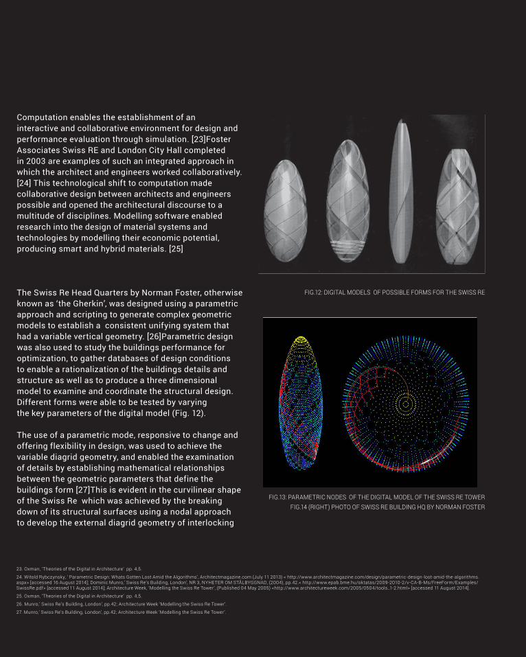
The Swiss Re Head Quarters by Norman Foster, otherwise
known as ‘the Gherkin’, was designed using a parametric
approach and scripting to generate complex geometric
models to establish a consistent unifying system that
had a variable vertical geometry. [26]Parametric design
was also used to study the buildings performance for
optimization, to gather databases of design conditions
to enable a rationalization of the buildings details and
structure as well as to produce a three dimensional
model to examine and coordinate the structural design.
Different forms were able to be tested by varying
the key parameters of the digital model (Fig. 12).
The use of a parametric mode, responsive to change and
offering flexibility in design, was used to achieve the
variable diagrid geometry, and enabled the examination
of details by establishing mathematical relationships
between the geometric parameters that define the
buildings form [27]This is evident in the curvilinear shape
of the Swiss Re which was achieved by the breaking
down of its structural surfaces using a nodal approach
to develop the external diagrid geometry of interlocking
FIG.12: DIGITAL MODELS OF POSSIBLE FORMS FOR THE SWISS RE
FIG.13: PARAMETRIC NODES OF THE DIGITAL MODEL OF THE SWISS RE TOWERFIG.14 (RIGHT) PHOTO OF SWISS RE BUILDING HQ BY NORMAN FOSTER
23. Oxman, ‘Theories of the Digital in Architecture’ pp. 4,5.
24. Witold Rybczynsky, ‘ Parametric Design: Whats Gotten Lost Amid the Algorithms’, Architectmagazine.com (July 11 2013) < http://www.architectmagazine.com/design/parametric-design-lost-amid-the-algorithms.aspx> [accessed 16 August 2014]; Dominic Munro,’ Swiss Re’s Building, London’, NR 3, NYHETER OM STÅLBYGGNAD, (2004), pp.42.< http://www.epab.bme.hu/oktatas/2009-2010-2/v-CA-B-Ms/FreeForm/Examples/SwissRe.pdf> [accessed 11 August 2014]; Architecture Week, ‘Modelling the Swiss Re Tower’, (Published 04 May 2005) <http://www.architectureweek.com/2005/0504/tools_1-2.html> [accessed 11 August 2014].
25. Oxman, ‘Theories of the Digital in Architecture’ pp. 4,5.
26. Munro,’ Swiss Re’s Building, London’, pp.42; Architecture Week ‘Modelling the Swiss Re Tower’.
27. Munro,’ Swiss Re’s Building, London’, pp.42; Architecture Week ‘Modelling the Swiss Re Tower’.

CONCEPTUALISATION 17

18 CONCEPTUALISATION
diagonal steel components (Fig.15 and 17). The circular
plan and tapering cucumber-like form, less bulky than
conventional block buildings, responds to the site specific
demands as the buildings slimmer profile increases
the degree of daylight penetration on lower levels while
maximizing the usable office space. It’s parametric form
encourages wind to flow around the building, making
the structure more efficient as the wind loads applied
to the cladding and structure are minimized.[28]
The ability to analyse the building in 3D provoked
collaboration between the team, ensuring a strong
logistic plan and accurate pricing for material, and
was used to develop the information required for
fabrication. “The continuity of model information
from analysis through to fabrication greatly reduced
the scope for errors in interpreting the design
requirements”[29]. The use of the 3D model enabled
detailed coordination of the trade interfaces from
cladding to services, from design to construction.[30]
FIG.17: THE NODAL CONNECTION USED FOR THE SWISS RE’S FACADE
FIG.16 EFFICIENCY OF FORM OF SWISS RE VERSUS A CONVENTIONAL BUILDING IN MINIMIZING WIND LOADS
FIG.15: THE GEODESIC FACADE OF THE SWISS RE
28. Architecture Week, ‘Modelling the Swiss Re Tower’.
29. Munro,’ Swiss Re’s Building, London’, pp. 42.
30. Architecture Week, ‘Modelling the Swiss Re Tower’.
CONCEPTUALISATION 19
A.3. Compositional and Generative Strategies
Architectural practice is being redefined by computation,
allowing architects to develop digital tools to expand the
possibilities in construction, fabrication and the design
process. Computation, the digital processing of information
and interactions of a specific environment of interrelated
elements, capable of complex forms, is essentially the
algorithmic expression of digitally processed information.
Just as architects moved from using computers as
computerization, simply digitizing existing procedures
as a ‘virtual drafting board’ to develop the designers
preconceived design, to the more complex realm of
computation that enables designers to augments their
ability to address complex problems, so too did the design
approach shift from compositional to generative. [31]
Shifting from Composition to Generation
With the embrace of computation, design strategies
shifted from an initial concern with achieving a desired
form, to producing a multitude of variations of a form
created to address set constraints on the design.
In traditional compositional strategies, the relationship
between the designer and the design is direct and the
architect retains control over how the overall form of
function of a design is produced. Computation is
used after the conception of the designs form, to
amend its basic shape for ease of construction or
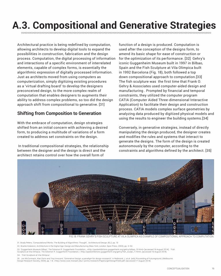
for the optimization of its performance. [32] Gehry’s
iconic Guggenheim Museum built in 1997 in Bilbao,
Spain and the Fish Sculpture at Vila Olimpica built
in 1992 Barcelona (Fig. 18), both followed a top
down compositional approach to computation.[33]
The fish sculpture was the first time that Frank O.
Gehry & Associates used computer-aided design and
manufacturing . Prompted by financial and temporal
constraints, they utilized the computer program
CATIA (Computer Aided Three-dimensional Interactive
Application) to facilitate their design and construction
process. CATIA models complex surface geometries by
analyzing data produced by digitized physical models and
using the results to engineer the building systems.[34]
Conversely, in generative strategies, instead of directly
manipulating the design produced, the designer creates
and modifies the rules and systems that interact to
generate the designs. The form of the design is created
autonomously by the computer, according to the
constraints and algorithms defined by the architect. [35]
31. Brady Peters, ‘Computational Works: The Building of Algorithmic Thought’, Architectural Design, 83,2, pp. 10
32. Branko Kolarevic, Architecture in the Digital Age: Design and Manufacturing (New York; London: Spon Press, 2003), pp. 3–62.
33. ‘Guggenheim Museum Bilbao’, The Solomon R. Guggenheim Foundation , <http://pastexhibitions.guggenheim.org/gehry/bilbao_15.html> [accessed 16 August 2014]; . ‘Fish Sculpture at Vila Olimpca’, The Solomon R. Guggenheim Foundation, < http://pastexhibitions.guggenheim.org/gehry/fish_sculpt_11.html>, [accessed 16 August 2014].
34. . ‘Fish Sculpture at Vila Olimpca’.
35. Jon McCormack, Alan Dorin and Troy Innocent, ‘Generative Design: a paradigm for design ressearch’, in Redmond, J. et al. (eds) Proceeding of Futureground, (Melbourne: Design Research Society, 2004), pp. 1-8. <http://www.csse.monash.edu/~jonmc/research/Papers/genDesignFG04.pdf> [accessed 17 August 2014].
FIG.18: FRANK GEHRY’S FISH SCULPTURE AT VILA OLIMPICA AS EXAMPLE OF COMPOSITIONAL APPROACH TO COMPUTATION.

20 CONCEPTUALISATION
Algorithmic thinking
Computation is essentially the algorithmic expression
of the digital processing of information and the
interactions of a specific environment of interrelated
elements, capable of complex forms. Unexpected
solutions that exceed the designers capabilities can
be generated by utilizing computer programs to solve
design problems, as the ability to modify the program,
or ‘sketch algorithmically’, makes a vast amount of
options available. [36] Algorithms are sets of precise
instructions of a specified procedure that are written in
code. [37] Most computer –aided design programs have
use programming or ‘scripting’ languages to implement
algorithms, tmaking designs by implementing the ability
to add, modify or erase elements of a model. However,
designers must understand algorithmic thinking to
fully benefit from these functions though. [38]
Computation in Practice
The increase in architecture practices use of computation
was driven by the availability and possibilities offered
by scripting languages such as Rhino Script, and
Grasshopper, a visual programming language, which are
used to tailor the design environments within existing
software. [39] Using these languages, computational
designers are able to make customized tools for designs
by writing and modifying algorithms that relate to
the configuration, placement and interrelationship
of its elements. [40] Such computational tools which
can simulate and analyze the performance of the
overall building as well as its structural, environment
and material performance, are able to be use these
constraints as parameters for generating architectural
forms. [41] But for computational techniques to be
effective, “the design environment, of which the
architect is now part author, must be flexible and
have the ability to accommodate change “. [42] As
design is shifting, design practices have become
inadequate, insufficient and as such, the organization
of architectural firms are changing to integrate
computational design expertise. [43] Typically, they do
so by fully integrating computation into their practice
and design process or with the employment of either
a long software designer, an internal specialist or an
external specialist consultant or hybrid designers
who are literate in computer programming and
scripting and develop their own design software.
However, having an internal specialist group is
not always necessary to develop computational
strategies, as networks of communal knowledge
are becoming readily available. Through online
forums like the Grasshopper community, designers
have access to a repository of digital tools, codes,
workflows and algorithms capable of being adapted
to their designs. Facilitated by computation, this
sharing and communal accumulation of codes, ideas
and tools is building algorithmic thought. [44]
Generation
Generative methodology incorporates dynamic processes
and outcomes and sees a shift from the conception of
an object, to envisaging the interaction between the
components, processes, and systems that generate
new products. The integration of generative systems
into the design process enables the production of
genuinely novel properties, that do not come from the
designers design concepts or expectations , and results
in unexpected forms thus enabling new design solutions
that were previously impossible to be achievable. [45]
The generative design process consists of four elements:
firstly the input of the parameters and conditions,
then the use of generative technique such as rules
and algorithms, followed by output, the generation
of design alternatives, and finally the evaluation and
selecting of the most efficient design alternative. [46]
36. Peters, ‘Computational Works’, pp. 10.
37. Peters, ‘Computational Works’, pp. 10; Robert Woodbury, ‘How Designers use Parameters’, in Theories of The Digital in Architecture (London; New York: Routledge, 2014), pp. 163.
38. Robert Woodbury, ‘How Designers use Parameters’, in Theories of The Digital in Architecture (London; New York: Routledge, 2014), pp. 163.
39. Peters, ‘Computational Works’, pp. 10.
40. Peters, ‘Computational Works’, pp. 11.
41. Peters, ‘Computational Works’, pp. 13.
42. Peters, ‘Computational Works’, pp. 11.
43. McCormack, Dorin and Innocent, ‘Generative Design’, pp. 1; Peters, ‘Computational Works’, pp. 11.
44. Peters, ‘Computational Works’, pp. 11.
45. McCormack, Dorin and Innocent, ‘Generative Design’ ,pp. 1-8.

CONCEPTUALISATION 21
FIG.19 THE STEPS OF A GENERATIVE DESIGN PROCESS
The four main properties of generative design systems
are: the ability to generate complexity, often in a dynamic
hierarchy; a relationship between the environment
and design that is complex and interconnected; the
capability for self maintenance and repair; and the
ability to give rise to new and original structures,
outcomes, behaviours or relationships. [47]
There are three broad categories of generative systems:
linguistic, biological and parametric. In linguistic
generative design strategies, design is governed
and shaped by a set of compositional rules that are
digitally manifested in shape grammars. This is where
a new, complex design is generated by an initial
object getting replaced by a new string of characters
according to defined modification rules. [48]
Biological generative design approaches use natural
emergence, the way complex natural systems grow,
evolve and self-organize to derive and transform the
forms of complex architectural and performative designs.
[49]. These evolutionary systems that digitally simulate
FIG.20 THE INTERACTIVATOR’S NETWORKED EVOLUTIONARY DESIGN FORMS
47. McCormack, Dorin and Innocent, ‘Generative Design’ ,pp. 3-4.
48. McCormack, Dorin and Innocent, ‘Generative Design’ ,pp. 6; Dino, ‘Creative Design Exploration’ pp. 209.
49. Dino, ‘Creative Design Exploration’ pp. 209.

22 CONCEPTUALISATION
the process of reproduction and natural selection,
breed the ‘fittest’ designs and are used to produce a
new generation of designs that inherit the successful
traits of their parents. [50] This architectural approach
is based on the concept of the genetic algorithm
that John Frazer defines as “a class of highly parallel
evolutionary, adaptive search procedures”. This genetic
algorithm, expressed as a set of generative rules,
allows the development and evolution of architectural
concepts to be digitally encoded.[51] Numerous
prototypical forms are produced by following these
generative script of instructions. These unexpected
emergent forms are then evaluated according to how
they perform in a simulated environment. [52]
The 1995 Interactivator by John and Julia Frazer
generated architectural form by following an evolutionary
approach . It experimented with evolution of the
forms produced by the interaction with environmental
sensors and visitors. Genetic algorithms were used
to pass knowledge and traits from the successful
generation to the future generation. [53]
Parametrics
In parametric design, it is the parameters or constraints
for a specific design, not the shape, that are defined.
The assignment of different values to these parameters
allows for the creation of different shapes, objects or
configurations, with the associate geometries defined
by the relationships between these objects. [54] The
effect of modifying the structures parameters on
the form is automatically determined by parametric
design software. [55] A computational method based
on algorithms, parametric tools enable greater
computational control over the designs geometric
form during the design process . As it acts in both
generative and analytical capacities, parametric design
can enable the performance analysis to be integrated
into the design [56] Parametric modelling provides new
design possibilities to play with and “creates endless
opportunities to explore for forms that are not practically
reachable otherwise” [57]. Design is evolving through the
constant exploration for new form-making possibilities.
Taking a parametric approach to design and construction
not only allows for high quality results to be delivered
on time and within budgets, but it also facilitates design
teams to work iteratively by providing a centralized
means to coordinate communication. The Aviva
Stadium in Dublin Ireland by Populus, was the first
building designed from conception to completion using
50. McCormack, Dorin and Innocent, ‘Generative Design’ ,pp. 1-8.
51. Kolarevic, ‘Architecture in the Digital Age’ :pp. 24-25
52. Kolarevic, ‘Architecture in the Digital Age’ :pp. 23-24.
53. . John Hamilton Frazer and Patrick Janssen, ‘Digital code scripts for gerneative and evolutionary design: De identitate’, < http://www.generativedesign.com/asialink/de6.htm> [accessed 17 August 2014].
54. Kolarevic, ‘Architecture in the Digital Age’ :pp. 17.
55. Allison Arief, ‘New Forms that Function Better’, MIT Technologyreview.com (July 31, 2013), < http://www.technologyreview.com/review/517596/new-forms-that-function-better/> [accessed 16 August 2014].
56. Dino, ‘Creative Design Exploration’ pp. 207.
57. Robert Woodbury, ‘How Designers use Parameters’, in Theories of The Digital in Architecture (London; New York: Routledge, 2014), pp. 165-166.

CONCEPTUALISATION 23
a parametric modelling software. A single model in
Bentley’s GenerativeComponents (GC) was used by both
architects and engineers to optimize the design of the
façade, structure and form. This parametric software
integrated structural analysis and automated the designs
fabrication. Working on a shared model facilitated
design conversations between disciplines and design
teams, acting as a conduit for information. At the core
of the workflow was a parametric geometry definition
shared by the architects and engineers. This defined
the control systems hierarchy that enabled the addition
of more control during the designs progression, and
separated the definition and control of the envelope
from that of the cladding and structural geometry. [58]
Using generative parametric design tools enabled
Populus to make modifications to the design, and based
on initial arbitrary “place-holder” parameter values in
the parametric model, the affected areas of the design
would respond accordingly. Not only did this allow
for more control over the geometry, but it also had
a knock-on effect when changes to the design were
made. This proved beneficial when they later needed
to amend the stadium’s radius, as the establishment
FIG. 21 INTERIOR OF AVIVA STADIUM
58. Roly Hudson, Paul Shepherd and David Hines, ‘Aviva Stadium: A case study in integrated parametric design’, International Journal of Architectural Computing, Vol. 9, Issue, 2 (June 2011), 188 191, < http://people.bath.ac.uk/ps281/research/publications/ijac_preprint2.pdf>, [accessed 17 August 2013].

24 CONCEPTUALISATION

CONCEPTUALISATION 25
FIG.22 THE AVIVA STADIUM, DUBLIN, IRELAND

26 CONCEPTUALISATION
of this control curve enabled them to locally control
the radius on the grid-lines around the stadium.
The constraints that the panels were to be four sided
planar polygons and that the designs underlying
geometry must be followed were imposed on
the cladding. These constraints, paired with the
control mechanism, enabled the investigation of
several design variations through rapidly produced
parametric models. As the overhead associated
with producing design iterations was reduced by
the use of this software, variations to the design
could be readily made and potential problems
FIG. 23 THE INTEGRATED WORKFLOW TO THE PARAMETRICAVIVA STADIUM
could be identified and resolved quickly. [59]
Throughout the design process, the architects and
engineers had their own focuses. As the architects
developed the buildings overall form and cladding, and
explored the form in response to criteria such as floor
area ratios and the shapes aesthetics, the engineers
addressed the sizing and positioning of the structural
members, as well as the structure of the cladding system
that operated as a rainscreen of interlocking louvres,
and the roof trusses. Through the simultaneous use
of a single parametric model that functioned as both a
design tool and a platform for coordination, it enabled
59. Hudson, Shepherd and Hines, ‘Aviva Stadium’, pp. 192-193.
60. Dino, ‘Creative Design Exploration’ pp. 213-214.
61. Hudson, Shepherd and Hines, ‘Aviva Stadium’, pp. 190.

CONCEPTUALISATION 27
the design process of the form, structure and façade to
be integrated, consequently allowing design changes to
be quickly responded to. [60] This ability for specialists
to work on different levels of the design in varying
detail, simultaneously, proved beneficial when there
was a downstream requirement to significantly alter the
design that otherwise would have been disastrous. [61]
Parametricism
Some designers, like Patrik Schumacher, use generative
strategies for the sole purpose of generating unusual
forms, rather than to solve problems. He goes beyond
using parametrics as a tool and embrace it as an enabler
of a new architectural aesthetic, which he coined
‘parametricisim’. A response to the heterogeneous nature
of society, this aesthetic promotes avoidance of axes,
symmetry, regularity, repetition, right angles, straight
lines and resemblance to anything from the past. [62]
Optimizing performance
Performative design arose with the emergence
of computation tools that can model a buildings
performance in terms of its structure, energy, lighting
and acoustics. Through parametric modelling,
energy-efficient solutions such as façade design
and optimizing window size, are able to be explored.
Although this sounds promising, this technology is
‘very elementary’, according to the director of the T.C.
Chan Centre for building Simulation and Energy Studies
at the University of Pennsylvania, Ali Malkawi. [63]
Even though Ali theorized that genetic algorithms
that mimic natural evolutionary processes, combined
with computational dynamics, could evaluate and
optimize design alternatives in terms of ventilation
and thermal performance, he stressed that achieving
this is still some distance in the future. Instead of
treating environmental conditioners of heating, air and
daylighting as integrated, current building simulation
models treat them separately. Furthermore they are
subject to unpredictable and external variables and
are dependent on the behaviour of its occupants,
the modelling of which is still rudimentary. [63]
The Shanghai Tower designed by Gensler, demonstrates
the benefits of parametric technology in optimizing
performance. Although its twisting form was an aesthetic
choice, the wind loads on the facade were minimized
by plugging the form into the parametric modelling tool
62. Rybczynsky, ‘ Parametric Design’ .
63. Rybczynsky, ‘ Parametric Design’ .
FIG. 24 OPTIMAL DEGREE OF ROTATION FOR SHANGHAI TOWER FOR REDUCING WIND LOADS

28 CONCEPTUALISATION
Site
Location: Lujiazui Finance and Trade Zone, Pudong district, Shanghai, China
Area: 30,370 square meters
Tower
Height: 632 metersStories: 121 occupied floors Area: 380,000 square meters above grade
141,000 square meters below gradeProgram: Office, luxury hotel, entertainment, retail,
and cultural venues
Podium
Height: 36.9 metersStories: 5 stories above gradeArea: 46,000 square metersProgram: Luxury retail, bank, restaurant, conference,
meeting, and banquet functions. Below-grade levels will house retail, 1,800 parking spaces, service, and MEP functions.
Owner, Developer, Contractor Shanghai Tower Construction & Development Co., Ltd.
Design Architect Gensler
Local Design Institute Architectural Design & Research Institute of Tongji University
Structural Engineer Thornton Tomasetti
MEP Engineer Cosentini Associates
Landscape Architect SWA
Project facts Team information
24 25
Gensler is a leading architecture, design, planning, and consulting firm with offices in the Americas, Asia, Europe, and the Middle East. Gensler Design Update is a publication announcing new projects of interest.
Gensler Design Update is produced by Gensler Publications. ©2010 Gensler.
www.gensler.com
Gensler Design Update is printed on FSC-certified, 10 percent postconsumer-waste paper with ultralow-VOC (–3 percent) vegetable oil–based ink. Savings to our natural resources include:
trees million BTUs of net energy gallons of wastewater pounds of solid waste
41
1,760107
FIG. 25 THE TWISTING FORM OF THE SHANGHAI TOWER

CONCEPTUALISATION 29
FIG. 26 COMPLEX GEOMETRY OF THE ROOF OF THE SMITHSONIAN INSTITUTION WITH LOCALLY ADAPTED COMPONENTS’
Site
Location: Lujiazui Finance and Trade Zone, Pudong district, Shanghai, China
Area: 30,370 square meters
Tower
Height: 632 metersStories: 121 occupied floors Area: 380,000 square meters above grade
141,000 square meters below gradeProgram: Office, luxury hotel, entertainment, retail,
and cultural venues
Podium
Height: 36.9 metersStories: 5 stories above gradeArea: 46,000 square metersProgram: Luxury retail, bank, restaurant, conference,
meeting, and banquet functions. Below-grade levels will house retail, 1,800 parking spaces, service, and MEP functions.
Owner, Developer, Contractor Shanghai Tower Construction & Development Co., Ltd.
Design Architect Gensler
Local Design Institute Architectural Design & Research Institute of Tongji University
Structural Engineer Thornton Tomasetti
MEP Engineer Cosentini Associates
Landscape Architect SWA
Project facts Team information
24 25
Gensler is a leading architecture, design, planning, and consulting firm with offices in the Americas, Asia, Europe, and the Middle East. Gensler Design Update is a publication announcing new projects of interest.
Gensler Design Update is produced by Gensler Publications. ©2010 Gensler.
www.gensler.com
Gensler Design Update is printed on FSC-certified, 10 percent postconsumer-waste paper with ultralow-VOC (–3 percent) vegetable oil–based ink. Savings to our natural resources include:
trees million BTUs of net energy gallons of wastewater pounds of solid waste
41
1,760107
Grasshopper to generate multiple design variations to
determine the optimal degree of rotation of the form. [64]
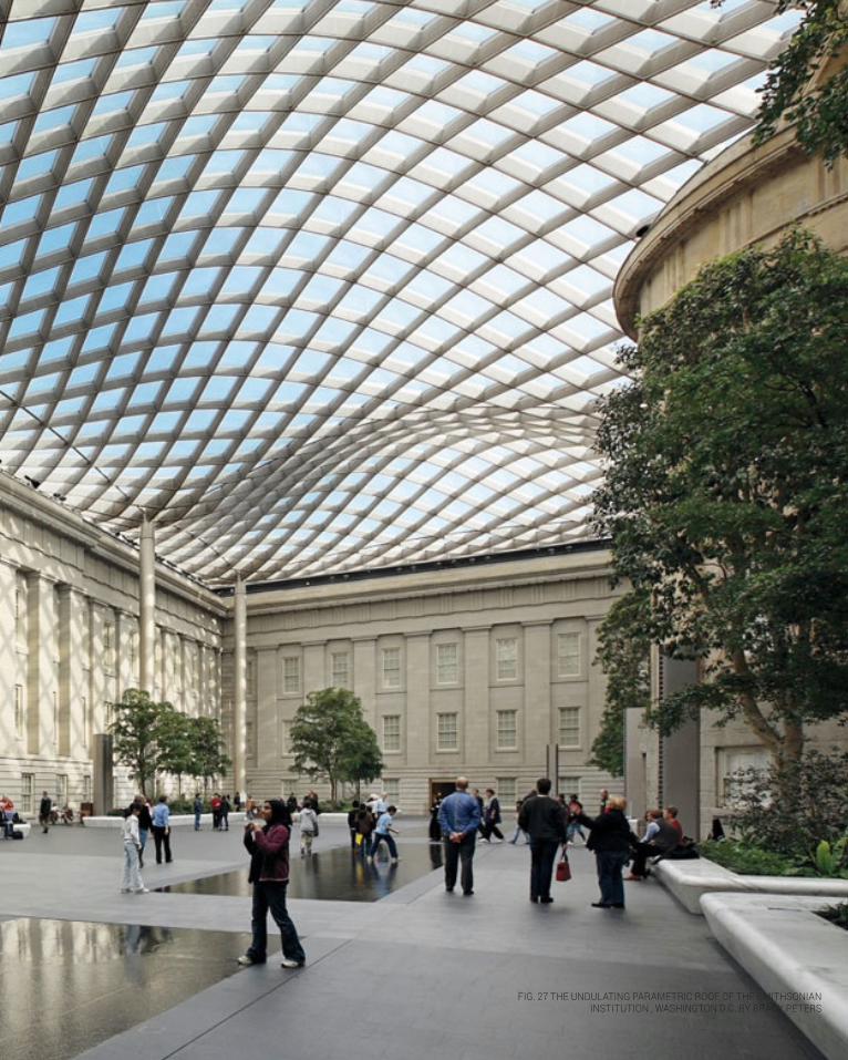
One of the many advantages of generative design is the
ability to relatively easily create and modify complex
geometries like that seen in the Courtyard Enclosure roof
of the of the Smithsonian Institution built in Washington
DC in 2007. [65] The geometry of this undulating roof
was generated with a single computer program created
by Brady Peters, a member of the Foster + Partners
design team and Specialist Modelling Group (SMG).
This computer code was modified constantly throughout
the design process and used in generating the final
geometry. It also generated additional information
required to visualize the space, analyze the designs
acoustic and structural performance and to fabricate
data to produce the physical model. [66] The entire roof
geometry was controlled by three surfaces, column
markers and this computer script that allowed for
the easy control and manipulation of the geometry.
Controlled by the parameters of the generative script
of a set-out geometry of a surface of simple control
lines, this code generated various roof components
64. Arief, ‘New Forms that Function Better’.
65. Brady Peters, ‘Smithsonian Institution’, <http://www.bradypeters.com/smithsonian.html> [accessed 17 August 2014].
66. Peters, ‘Computational Works’, pp. 13
67. Brady Peters, ‘Smithsonian Institution’.

30 CONCEPTUALISATION
CONCEPTUALISATION 31
FIG. 27 THE UNDULATING PARAMETRIC ROOF OF THE SMITHSONIAN INSTITUTION , WASHINGTON D.C. BY BRADY PETERS
32 CONCEPTUALISATION
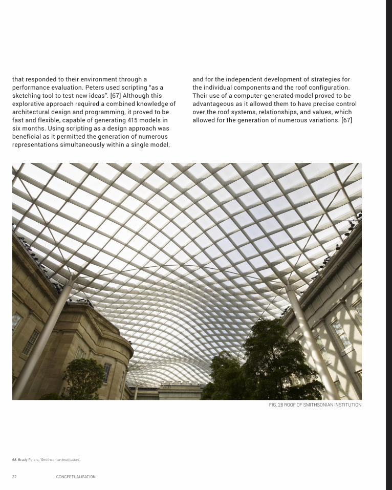
that responded to their environment through a
performance evaluation. Peters used scripting “as a
sketching tool to test new ideas”. [67] Although this
explorative approach required a combined knowledge of
architectural design and programming, it proved to be
fast and flexible, capable of generating 415 models in
six months. Using scripting as a design approach was
beneficial as it permitted the generation of numerous
representations simultaneously within a single model,
68. Brady Peters, ‘Smithsonian Institution’,.
FIG. 28 ROOF OF SMITHSONIAN INSTITUTION
and for the independent development of strategies for
the individual components and the roof configuration.
Their use of a computer-generated model proved to be
advantageous as it allowed them to have precise control
over the roof systems, relationships, and values, which
allowed for the generation of numerous variations. [67]

CONCEPTUALISATION 33
A.4. Conclusion
The emergence of computerization marked an epoch in
architectural design. From it evolved computation with
algorithmically based parametric tools like Rhino and
Revit, which offere greater complexity and flexibility,
producing more unique designs. Abstract, curvilinear and
gravity defying complex geometries that were previously
unimaginable became conceivable and achievable. Early
computationally achieved designs like Frank Gehry’s
Guggenheim Museum, focused on embraced these newly
achievable forms, implemented computational tools to
make their designs a reality. Furthermore, supplemented
by Building Information Modelling, computation has
also opened up a realm of collaborative and multi-
disciplined design, which was seen in use of a single
digital model in the development of the Aviva Stadium.
Although architects are still designing, we are
moving into such a digitized age that they are now
also programming. The hybrid software developer/
architect who can develop algorithmic software
specific to a design that becomes integrated into
the design process, is becoming more prevalent.
Through the integration of such software architects
ventured into an exploration of form-finding through
designs generated by algorithms. Architects have begun
optimizing building structure, material use, energy
efficiency and cost by utilizing software that analyses
and simulates the building based on performance
and evidence. We are seeing a move towards more
sustainable, efficient and user-friendly buildings.
Through the scripting of design specific programs,
complex geometries can be created and manipulated,
that following defined constraints, generate a vast
array of design options. A vast array of novel and
unexpected designs can be quickly generated and their
performance evaluated. Repetitive processes have
been relegated to the computer to produce variations
or randomly generate patterns based on parametric,
linguistic or biological processes. Despite this, generative
design approaches haven’t been widely adopted as
it is relatively new and its performative possibilities
are still in their early stages of development.
Throughout this project, I intend to undertake a
generative design approach to form-finding, embracing
computation to explore the possibilities of parametric
design. Using Grasshopper to experiment with varying
the inputs, parameters, and components to generate
a variety of forms and test the designs capabilities, I
aspire to develop designs that are not only successful
in their functionality and aesthetics, but are inherently
novel, unique, and perhaps most importantly, something
I wouldn’t have dreamed of developing solely by hand.
My hope is that this design approach will extend
my capabilities through computation, and will also
widen my imagination and open up a world of new
forms that offer a multitude of design possibilities.

34 CONCEPTUALISATION
A.5. Learning Outcomes
Entering this subject four weeks ago, I had very little
experience with Rhino, none with Grasshopper and rather
embarrassingly, barely any with computerization let
alone computation. I hadn’t even heard of those terms
prior to this subject. Basically I’m a novice. While I’m not
at all saying that this is no longer the case, I now have
some experience with Grasshopper and have started to
delve into the realm of parametrics. If I had been able
to use even the little bit of the knowledge I have been
able to gain thus far, I may have been able to further
explore the design possibilities of my project for Design
Studio Earth. By changing the parameters applied to the
angled wall, I could have explored a variety of forms and
patterns and generated a more complex geometry, to
either complement or contrast with the designs situation
within the surrounding landscape. I possibly would have
even been able to integrate the pattern of the rock statue
into a geometric pattern along the long, bending wall.
FIG. 29 RHINO MODEL FOR DESIGN STUDIO EARTH FINAL PROJECT WHICH WAS MY FIRST TIME USING RHINO
FIG. 30 MONTAGE OF SITE PHOTO AND RHINO MODEL FOR DESIGN STUDIO EARTH FINAL PROJECT

CONCEPTUALISATION 35
These spheres (Fig. 32) are some of the variations
I produced for the algorithmic sketch task we were
assigned to do in week 3 in which we recreated the
façade of RMIT Building 80 and altered the colour and
size of the triangles by manipulating the algorithm
in Grasshopper. Cull index and list item were used to
generate different lists of triangles that can have varying
colours applied to them. By splitting cull indexes in two,
using cull patterns, culling every Nth item, or setting
a domain, I was able to produce different patterns.
I then decided to explore the geometries I could apply
this to beyond varying surfaces I could produce by
manipulating the control points of the original curve, and
plugging this algorithm into a sphere that I generated in
Rhino by substituting it for the curve input component.
I chose to include this example from my Algorithmic
sketchbook, as it is the most complex form and the
most complex algorithm I have worked with to date.
Its quite a leap forward from my first attempt at
creating and generating an algorithm which I did in
the week 1 task (Fig. 31). Even though this example
I produced is not remarkably different from what we
did in the tutorial, it is the furthest I have been able
to explore beyond the tutorial and video materials.
This algorithmic sketch task, like the others I have done,
has supplemented the theory on generative design
that was covered in the lectures and reading material.
The hands on experience of actually being able to get
involved in the form-finding generative design strategy,
manipulating the parameters and components of the
algorithm to produce variations in the design, has helped
me better understand the possibilities it holds in both
being able to generate such complex patterns, and also
the speed and ease with which variations can be made.
Furthermore, the complexity of even the relatively
simple the algorithms for some of these tasks has
helped me gain an appreciation for not only why good
code is so valuable, and why architects favour the copy
and paste approach when dealing with algorithmic
code, but also how difficult it is to generate code.
FIG. 31 WEEK 1 ALGORITHMIC SKETCH OF GENERAL TOWER VOLUME
FIG 32. WEEK 3 ALGORITHMIC SKETCH TO GENERATE VARIATIONS OF THE RMIT BUILDING 80 FACADE PATTERN
A.6. Appendix: Algorithmic Sketches

36 CONCEPTUALISATION
Architecture Week, ‘Modelling the Swiss Re Tower’, (Published 04 May 2005) < http://www.
architectureweek.com/2005/0504/tools_1-2.html> [accessed 11 August 2014].
Arief, A., ‘New Forms that Function Better’, MIT Technologyreview.com (July 31, 2013), < http://www.
technologyreview.com/review/517596/new-forms-that-function-better/> [accessed 16 August 2014].
Cuny, J., L. Snyder, and J. M. Wing, “Demystifying Computational Thinking for Non-Computer Scientists,” work in progress, 2010.
Decker, M. and P.Yeadon, ‘Light Sanctuary: An empowered landscape for the UAE’, Land Art Generator Initiative
2010 Competition <http://landartgenerator.org/LAGI2010/8s3b9u/> [accessed 2 August 2014].
Diehl, G. X. Liu, A. Braleret and L. Santamaria, ‘Photoreactor Farm Tower’, Land Art Generator Initiative 2010
Competition, <http://landartgenerator.org/LAGI2010/co2po4/> [accessed 1 August 2014].
Dino, I. G., ‘Creative Design Exploration by Parametric Generative systems in Architecture’, METU Journal of Faculty of Architecture 29, 1,
(2012), pp. 207-224, < http://jfa.arch.metu.edu.tr/archive/0258-5316/2012/cilt29/sayi_1/207-224.pdf> [ accessed 17 August 2014].
Ferry, R., and E. Monoian ‘Design Guidelines: Land Art Generator Initiative’, Land Art Generator Initiative, Copenhagen
<http://landartgenerator.org/images/LAGI2010DESIGNGUIDELINES.pdf> [accessed 1 August 2014].
‘Fish Sculpture at Vila Olimpca’, The Solomon R. Guggenheim Foundation, < http://pastexhibitions.
guggenheim.org/gehry/fish_sculpt_11.html>, [accessed 16 August 2014].
Frazer, J.H., and P. Janssen, ‘Digital code scripts for generative and evolutionary design: De identitate’,
< http://www.generativedesign.com/asialink/de6.htm> [accessed 17 August 2014].
Fry, T., Design Futuring: Sustainability, Ethics and New Practice (Oxford: Berg, 2009), pp. 1-16.
‘Guggenheim Museum Bilbao’, The Solomon R. Guggenheim Foundation , <http://pastexhibitions.
guggenheim.org/gehry/bilbao_15.html> [accessed 16 August 2014].
Hudson, R., P. Shepherd and D. Hines, ‘Aviva Stadium: A case study in integrated parametric design’, International Journal of Architectural
Computing, Vol. 9, Issue, 2 (June 2011), 188 – 203, < http://people.bath.ac.uk/ps281/research/publications/ijac_preprint2.pdf
12>, [accessed 17 August 2013].
Kalay, Y.E., Architecture’s New Media: Principles, Theories, and Methods of Computer-Aided Design (Cambridge, MA: MIT Press, 2004), pp. 5–25.
Kolarevic, B., Architecture in the Digital Age: Design and Manufacturing (New York; London: Spon Press, 2003), pp. 3–62.
Lynn, G. eds., ‘Folding in Architecture, Architectural Design’ (Wiley-Academy: West Sussex, UK, 1993), in Oxman Rivka
and Robert Oxman, eds (2014). Theories of the Digital in Architecture (London; New York: Routledge), pp. 2.
McCormack, J., A. Dorin and T. Innocent, ‘Generative Design: a paradigm for design research’, in Redmond, J.
et al. (eds) Proceeding of Futureground, (Melbourne: Design Research Society, 2004), pp. 1-8. <http://www.
csse.monash.edu/~jonmc/research/Papers/genDesignFG04.pdf> [accessed 17 August 2014].
McManus, D.,‘Aviva Stadium Dublin, Aireland: Architecture Information + Images, e-architect, March 6,
2014, <http://www.e-architect.co.uk/dublin/aviva-stadium> [accessed 17 August 2014]
Munro, D., ‘Swiss Re’s Building, London’, NR 3, NYHETER OM STÅLBYGGNAD, (2004), pp.36-43.< http://www.epab.bme.
hu/oktatas/2009-2010-2/v-CA-B-Ms/FreeForm/Examples/SwissRe.pdf> [accessed 11 August 2014].
Oxman, R. and R. Oxman, eds. Theories of the Digital in Architecture (London; New York: Routledge, 2014), pp. 1–10
Peters, B. ‘Computational Works: The Building of Algorithmic Thought’, Architectural Design, 83,2, pp. 08-15.
Peters, B., ‘Smithsonian Institution’, <http://www.bradypeters.com/smithsonian.html
> [accessed 17 August 2014].
Rybczynsky, W., ‘Parametric Design: Whats Gotten Lost Amid the Algorithms’, Architectmagazine.com (July 11 2013) <http://
www.architectmagazine.com/design/parametric-design-lost-amid-the-algorithms.aspx> [accessed 12 August 2014].
Terzidis,K., Algorithms for Visual Design Using the Processing Language (Indianapolis, IN: Wiley, 2009).
Woodbury, R., ‘How Designers use Parameters’, in Theories of The Digital in Architecture (London; New York: Routledge, 2014), pp. 153-170.
Part A Reference List

CONCEPTUALISATION 37
Cover: McCollam, P ‘Hilly’, image, Structural Surface, <http://paulmccollam.com/wp-content/uploads/hilly.jpg> [accessed 4 August 2014].
Fig. 1 Waring, S., ‘Rhino Model of Deign of Final Project for Design Studio Earth’, Rhino Model screen captures, 2014.
Fig. 2 - 4 Diehl, G., X. Liu, A. Braleret and L. Santamaria, ‘Photoreactor Farm Tower’, Land Art Generator Initiative
2010 Competition, <http://landartgenerator.org/LAGI2010/co2po4/> [accessed 1 August 2014].
Fig. 5 - 7 Decker, M. and P. Yeadon, ‘Light Sanctuary: An empowered landscape for the UAE’, Land Art Generator
Initiative 2010 Competition <http://landartgenerator.org/LAGI2010/8s3b9u/> [accessed 2 August 2014].
Fig. 8 Gomez, F. ‘Sketches of Frank Gehry: Gehry’s Sketch of The Guggenheim Bilbai, Spain’, courtesy of Sony Pictures Classics, < http://
www.2flashgames.com/mp/2006_Sketches_of_Frank_Gehry/2006_sketches_of_frank_gehry_014.jpg> [accessed 11 August 2014].
Fig. 9 Flickr User Cincinnato: EEPaul, ‘Architecture Photography: AD Classics: the Guggenheim Museum Bilbao/Frank Gehry(422475)”,
Archdaily < http://www.archdaily.com/422470/ad-classics-the-guggenheim-museum-bilbao-frank-gehry/521fa08fe8e44eb94a000037_
ad-classics-the-guggenheim-museum-bilbao-frank-gehry_flickr_user_cincinnato-jpg/ > [accessed 11 august 2014]
Fig. 10 Katy and Scott, ‘The Guggenheim Museum designed by Frank Gehry’, uploaded July 10th 2008 < http://
www.karieandscott.com/blog/wp-content/uploads/2008/07/img_0489.jpg> [accessed 11 August 2014]
Fig. 11 ‘The translation process in Gehry’s office: [a] digitized points; (b) digital surface reconstruction; and (c) digitally fabricated
model’, in Kolarevic, B., Architecture in the Digital Age: Design and Manufacturing (New York; London: Spon Press, 2003), pp. 31.
Fig. 12 Foster and Partners, ‘By varying key parameters, the design team was able to quickly test numerousforms’,Architectureweek,
www.architectureweek.com/cgi-bin/awimage?dir=2005/0504&article=tools_1-2.html&image=12686_image_4.jpg >, [accessed 11 August 2014].
Fig. 13: Foster and Partners, ‘ Parametric nodes of the tower’s computer model’ http://www.architectureweek.com/cgi-
bin/awimage?dir=2005/0504&article=tools_1-1.html&image=12686_image_2.jpg> [accessed 11 August 2014].
Fig. 14 Young, N., ‘Architecture Photography: The Gherkin Receives CTBUH’s Inaugural 10 year Award (406795)”, Archdaily, < http://www.
architectureweek.com/cgi-bin/awimage?dir=2005/0504&article=tools_1-2.html&image=12686_image_7.jpg> [accessed 11 August 2014].
Fig. 15 ‘The geodesic façade of the Swiss Re’ in Munro, D. (2004) Swiss Re’s Building, London, NR 3, NYHETER OM STÅLBYGGNAD, pp.36-
43.< http://www.epab.bme.hu/oktatas/2009-2010-2/v-CA-B-Ms/FreeForm/Examples/SwissRe.pdf>, p. 40 [accessed 11 August 2014].
FIG. 16 Foster and Partners, ‘The Swiss Re tower compared to a conventional rectilinear building in reducing wind loads and turblence’ < http://
www.architectureweek.com/cgi-bin/awimage?dir=2005/0504&article=tools_1-2.html&image=12686_image_7.jpg> [accessed 11 August 2014]
Fig. 17. ‘The produced node is prefabricated in the factory’, in Munro, D. (2004) Swiss Re’s Building, London, NR 3, NYHETER OM STÅLBYGGNAD,
pp.36-43.< http://www.epab.bme.hu/oktatas/2009-2010-2/v-CA-B-Ms/FreeForm/Examples/SwissRe.pdf>, p. 40 [accessed 11 August 2014].
Fig. 18 Shayan, ‘The Frank Gehry Fish and the Barcelona Grand Casino’, photograph, retrieved
from http://www.everystockphoto.com/photo.php?imageId=2768227.
Fig. 19 Adapted from: McCormack, J., A. Dorin and T. Innocent, ‘Generative Design: a paradigm for design research’,
in Redmond, J. et al. (eds) Proceeding of Futureground, (Melbourne: Design Research Society, 2004), pp. 1-8. <http://
www.csse.monash.edu/~jonmc/research/Papers/genDesignFG04.pdf> [accessed 17 August 2014].
Fig. 20 Frazer, J., J. Frazer, M. Rastogi, P. Graham, P. Janssen, ‘Interactivator: Networked Evolutionary Design System’, Computational
model, (London: Architectural Association, 1995), retrieved from John Hamilton Frazer and Patrick Janssen, ‘Digital code scripts
for generative and evolutionary design: De identitate’, < http://www.generativedesign.com/asialink/de6.htm> [accessed 17 August 2014].
Fig. 21 Hines, D. ‘Aviva Stadium interior’, photograph, Grasshopper, posted 3 September 2013, < http://
www.grasshopper3d.com/photo/aviva-stadium-5?context=user>, [accessed 17 August 2014].
Fig. 22 Hines, D‘Aviva Stadium’, photograph, Grasshopper, posted 3 September 2013, <http://www.
grasshopper3d.com/photo/aviva-stadium-8/next?context=user>, [accessed 17 August 2014].
Part A Image Reference List

38 CONCEPTUALISATION
Fig. 23 Hines, D. ‘Aviva Stadium workflow’, diagram of workflow, Grasshopper, posted 3 September 2013, <
www.grasshopper3d.com/photo/aviva-stadium-8/next?context=user>, [accessed 17 August 2014].
Fig. 24 Gensler, ‘optimal rotation of tower to reduce wind loads’, model, retrieved from ‘Gensler Design Update: Shanghai Tower’,
pp. 6, <http://www.gensler.com/uploads/documents/Shanghai_Tower_12_22_2010.pdf> [accessed 17 August 2014].
Fig. 25 Gensler, ‘The Shanghai Tower’, model, retrieved from ‘Gensler Design Update: Shanghai Tower’, pp.
24, <http://www.gensler.com/uploads/documents/Shanghai_Tower_12_22_2010.pdf> [accessed 17 August 2014].
Fig. 26 Peters, B., ‘Complex geometry of roof with locally adapted components’ , photograph and model,
retrieved from http://www.bradypeters.com/smithsonian.html, [accessed 17 August 2014]
Fig. 27 Foster and Partners, ‘Smithsonian Institution Roof and interior’, photograph, retrieved from <http://
www.fosterandpartners.com/media/Projects/1276/img0.jpg >[accessed 17 August 2014].
Fig. 28 Foster and Partners, ‘Smithsonian Institution Roof’, photograph, retrieved from http://www.
fosterandpartners.com/media/Projects/1276/img1.jpg, [accessed 17 August 2014].
Fig. 29 Waring, S., ‘Rhino Model of Deign of Final Project for Design Studio Earth’, Rhino Model screen captures, 2014.
Fig. 30 Waring, S., ‘Photomontage of Design of Final Project for Design Studio Earth’, Rhino Model montaged with photo, 2014.
Fig. 31 Waring, S., ‘Week 1 Algorithmic Sketch Task’, Design Studio Air Sketchbook, 2014, pp. 5.
Fig. 32 Waring, S., ‘Week 3 Algorithmic Sketch Task’, Design Studio Air Sketchbook, 2014, pp. 16.

CRITERIA DESIGN 39

40 CRITERIA DESIGN

PART B: CRITERIA DESIGN
CRITERIA DESIGN 41

42 CRITERIA DESIGN
B.1. Research Field: Geometry
For my research field I chose the rather broad system
of ‘Sectioning’, that involves sysems of contours,
slices and grids. I was drawn by the systematic,
logical and creative manner in which variations
in the sectional planes can not only generate a
coherent surface but also define a space.
Computer modeling has expanded orthographic
representational tools of plans and sections beyond
two dimensional drawings and projections to a
method of cutting cross-sections through established
three dimensional forms, known as sectioning. The
technique of sectioning has proven to be effective
construction process as designs increasingly incorporate
complex geometries, being commonly used to make
the curving surfaces of airplanes and ships.1
Often occurring on a one-to-one scale and liaising
between digital production and manufacturing,
sectioning fabrication techniques . are often used as
a production strategy for 2D fabrication of models and
later of actual buildings. Instead of constructing the
forms surface, the digitally driven sectional methodology
involves using sectioning or contouring commands
of modeling software on the digital model to extract
a series of 2D planar components from the buildings
geometrically complex form. The sequence of edge
profiles produced that follow the surface geometry
are used as a set of parallel planes that cut a whole
surface into pieces or ‘ribs’ at set intervals established
by the thickness of the given material . Plotted at full
scale, these sections are used as templates from which
to cut the material, streamlining the construction
and assemblage process, with the ‘ribs’ capable of
generating both the surface and structure of a design.2
These sections which can generate both the surface
and structure of a design, are fabricated using
computerized cutting tools such as laser cutters and
1 Lisa Iwamoto, Digital Fabrications: Architectural and Material Techniques (New York, Princeton Architectural Press, N.D., p. 4-17 <http://atc.berkeley.edu/201/readings/Iwamoto_Digital_Fabrications.pdf>
2 Iwamoto, Digital Fabrications,p. 10-17.
FIG 33. GRID OF WEBB BRIDGE
numerically controlled computers, a cutting technology
called CNC routers, which work off digital files of the
profiles.3 The introduction of these tools meant that
manual labour was no longer required to construct
the pieces, and enabled the production of precision
models. Furthermore, the coupling of these tools with
digital design software generated a shift from their
use to make models, to non-standard form making and
the realization of the potential for the representational
method of sectioning to be used as a building technique.4
Sectioning construction techniques are diverse
3 Carlos L. Marcos, ‘New Materiality: Digital Fabrication’ in: IMproVe 2011 – International Conference on Innovative Methods in Product. P. 1044.
4 Iwamoto, Digital Fabrications,p. 10-17.

CRITERIA DESIGN 43
with varying interpretations of its eloquently simple
tectonic of grids, stacks and layers. Almost limitless
design possibilities are ensured by the intermediary
calibration between the digital and physical sectioning.
Sectioning allows architects to describe a surface
through the implied visual continuity of edge profiles
that merges and advances the relationship between
material tectonic and form. This is evident with
stacking, as the frequency of the sections proportionally
increases with the surface geometry, consequently
increasing the materials visual intensity.5
5 Iwamoto, Digital Fabrications,p. 10-17.
FIG 34. SECTIONAL GRID OF WEBB BRIDGE
The Webb Bridge by Denton Corker Marshall and
Robert Owen employed sectioning to create a grid
of curved ribs that encircle the deck of the bridge,
forming a volume from their sectional sinous
form. These ribs that vary in size are constructed
from prefabricated steel sections and connected
by steel straps.The bridge is not only a light,
volominous object with dilineated structure, its
dynamic and transitional space created by its
sectional approach makes it a place of action.6
6 Denton Corker Marshall, ‘Webb Bridge’, in The Australian Insitutte of Architectus (2013)< http://dynamic.architecture.com.au/awards_search?option=showaward&entryno=20053006> [accessed 27 August 2014]..

44 CRITERIA DESIGN
The advantages of sectional techniques are evident
in hollow construction , in which a form is divided into
sections of structural ‘ribs’ that are then clad with a
surface material, as it produces a lightweight structure
with accurate profiles onto which a surface material
can be applied. The implementation of sectioning for
the geometry and construction in making curved forms
are apparent in Le Corbusier’s chapel at Ronchamp.
Its roof used the hollow construction technique, with a
series of structural concrete ribs laterally connected by
crossbeams and clad in thin shells of concrete.7 When
in adequate proximity, a collection of ribs can even
form the complex surface as well as the structure.8
Greg Lynn experimented with the aesthetics possible
7 Iwamoto, Digital Fabrications,p. 10-16.
8 Carlos L. Marcos, ‘New Materiality’. P. 1044..
when using digitally generated sectional construction
as a design methodology, and observed a change
in the aesthetics when moving from Cartesian
defined volumes to surfaces defined by vector
coordinates that had an organized fluidity to them.9
The curvilinear and parametrically nuanced design
of One Main Street by dECOI Architects employs a
sectional approach combining ready made components
with customized fabrication by using Computer-Aided-
Design (CAD) and Computer-Aided Manufacturing
(CAM) processes, building the project entirely from 3D
instructional files instead of plans and sections.10
9 Iwamoto, Digital Fabrications, p. 10-16.
10 dECOi architects, ‘OneMain Street;, (2011), <http://www.decoi-architects.org/2011/10/onemain/> [accessed 28 August 2014].
FIG 35. INTERIOR SPACE OF ROOF OF CORBUSIERS RONCHAMP SHWOING CONCRETE RIBS
FIG 36. EXTERIOR OF THE ROOF OF CORSBUIERS RONCHAMP

CRITERIA DESIGN 45
The overall form of the design, which reads as a
coherent unbroken whole, composed of plywood strip
sections was fabricated as a collection of sectional
elements cut from plywood sheets milled using a
CNC router, according to digital path instructions.
The ability to maintain a continuity of the surface the
design was able to maximize temporal, material and
economic efficiency in its assemblage. The customized
prefabricated parts created an apparent unity in form
and surface and allowed for quickly on-site installation.
Furthermore, the dECOI Architects were able to employ an
FIG 38. PLYWOOD PLANES THAT FORM THE CURVING ROOF SURFACE
FIG 39. INSTALLATION OF PLYWOOD SECTIONS TO FORM SURFACES FIG 37. INSTALLATION OF PLYWOOD SECTIONS THAT FORM ROOF SURFACE
FIG 40. DIGITAL MODEL OF DESIGN FROM WHICH THE PLYWOOD SECTIONS WERE CUT FROM ACCORDINGLY

46 CRITERIA DESIGN

CRITERIA DESIGN 47
environmental objective in their sectioning methodology
with the efficient translation of the sustainable, carbon
absorbing raw plywood into its functional elements
using low energy digital cutting technology.
To maximize efficiency, dECOI scripted algorithms
for generating the milling protocols that create
the complex, curved edges of the plywood sheets.
These protocols analyzed the surface geometry and
automatically divided it sections that were then cut using
a millwork fabricator with a CNC router accordingly.
In other words, the designs of the plywood sections
were digitally issued as cutting instructions for the
CNC router. Using these algorithms allowed for a
seamless transfer from design to fabrication as well
as a high accuracy and minimal error and wastage.
dECOI’s design demonstrates the seamless
fabrication process and consideration of economic,
environmental, and material opportunities
possible when utilizing a sectioning system.11
11 dECOi architects, ‘OneMain Street’.
FIG 41. ONE MAIN STREET INTERIOR WITH SECTIONS CREATING A COHERENT SURFACE

48 CRITERIA DESIGN
B.2. Case Study 1.0: BanQ
BanQ by architects Office dA, is a restaurant at the
base of the old Penny Savings Bank in Boston. While
its function is divided into two segments, a bar and a
dining area, the space is designed around a division
on the z-axis between the floor and the ceiling.
The architect’s design responded to the requirement
of the ground to remain flexible to accommodate the
changing restaurant activities by containing the fixed
infrastructural elements of the building such as the
structure, drainage, mechanical equipment and lighting
within the ceiling. To conceal the infrastructure, the
architects developed a canopied ceiling out of striated
wood-slated system using a sectioning construction
strategy. The geometry and radius of the wooden slat
was generated to correspond to the infrastructure
above, concealing it with a seamless surface of
panels. From the longitudinal axis, the illusion of a
seamless surface is emphasized and the services
are concealed, while the infrastructure above is seen
in glimpses between the slats from lateral views.1
The sectional wooden slats of the undulating ceiling
create an overall striping affect that plays throughout
the restaurant space with the ribs appearing to sway
1 “BanQ / Office dA” 03 Dec 2009. ArchDaily. Accessed 06 Sep 2014. <http://www.archdaily.com/?p=42581>
Introducing BanQ by Office dA
FIG 42. PHOTOS OF SECTIONAL APPROACH TO BANQ BY OFFICE DA
FIG 43. PHOTOS OF SECTIONAL APPROACH TO BANQ BY OFFICE DA (TOP)FIG 44. COLUMN OF BANQ(RIGHT)

CRITERIA DESIGN 49
FIG 42. PHOTOS OF SECTIONAL APPROACH TO BANQ BY OFFICE DA
FIG 43. PHOTOS OF SECTIONAL APPROACH TO BANQ BY OFFICE DA (TOP)FIG 44. COLUMN OF BANQ(RIGHT)

50 CRITERIA DESIGN
FIG 45. EXPLODED PERSPECTIVE OF BANQ BY OFFICE DA
as a single unit.2 The ceiling is suspended from
above, with each rib running the width of the
space. The ribs are single, customized continual
pieces of plywood that fit together like a puzzle,
with each piece having a specific location, creating
a coherent and apparently continuous surface. The
spacing between the ribs varies to maintain the
overall surfaces visual density, while the variation
in the shape of the ribs are for aesthetics and to
define space. The changes are minute along the
ceiling to create a gentle flowing aesthetic, while
drastic changes in shape occur where the ribs
curve down and touch the ground to form the wall
columns.3 The ceiling essentially acts as the stage
from which the design occurs with the ‘intersection
of the extraordinary with the totally conventional’. 4
I used this design as my case study from
which to explore the reach of its algorithmic
definition as I thought it provided the opportunity
to generate vastly different outcomes by
manipulating its parameters and the definition
itself, testing its limits. Furthermore, I was
drawn to its strategy of the overall form
following function, but not being confined by
it, as while the form hides the infrastructure
2 David Sokol, ‘Banq’, Australian Design Review’, (2009), <http://www.australiandesignreview.com/interiors/661-banq> [accessed 29 August 2014].
3 BanQ / Office dA” . ArchDaily.
4 David Sokol, ‘Banq’.

CRITERIA DESIGN 51
FIG. 46 PHOTOS OF SECTIONAL APPROACH TO BAN! BY OFFICE DA1 1 photographed by John Horner, “BanQ / Office dA” 03 Dec 2009. ArchDaily. Accessed 06 Sep 2014. <http://www.archdaily.com/?p=42581>
FIG 47. PHOTOS OF SECTIONAL APPROACH TO BAN! BY OFFICE DA1 1 photographed by John Horner, “BanQ / Office dA” 03 Dec 2009. ArchDaily. Accessed 06 Sep 2014. <http://www.archdaily.com/?p=42581>
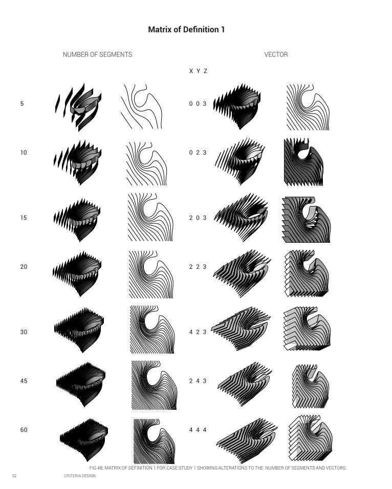
52 CRITERIA DESIGN
NUMBER OF SEGMENTS VECTOR
5
10
15
20
30
45
60
0 0 3
0 2 3
2 0 3
2 2 3
4 2 3
2 4 3
4 4 4
X Y Z
Matrix of Definition 1
FIG 48. MATRIX OF DEFINITION 1 FOR CASE STUDY 1 SHOWING ALTERATIONS TO THE NUMBER OF SEGMENTS AND VECTORS

CRITERIA DESIGN 53
MODIFYING SHAPE OF INPUT SURFACE MODIFYING INPUT SURFACE SHAPE BY MANIPULATING CONTROL POINTS
FIG 49. MATRIX OF DEFINITION 1 FOR CASE STUDY 1, ALTERATIONS TO THE INPUT SURFACE

54 CRITERIA DESIGN
MODIFYING INPUT SURFACE AND CURVE
FIG 50. MATRIX OF DEFINITION 1 FOR CASE STUDY 1 ALTERING INPUT SURFACE AND CURVE TO PRODUCE INTERWEAVING AND INTERLOCKING RESULTS

CRITERIA DESIGN 55
Matrix of definition 2
(2,3)
(2,4)
(2.5)
(2,6)
(2,7)
(2,8)
(2,9)
CHANGING VECTORS THAT DIVIDE THE SURFACE (U, V)
(6,2)
(8,2)
(5,6)
(10,6)
(5,8)
(10,8)
(5,10)
ALTERING THE INPUT IMAGE FROM WHICH THE PATTERN
Increasing V Changing U & V
FIG 51. MATRIX OF DEFINITION 2 FOR CASE STUDY 1 ALTERING THE INPUT VECTORS AND IMAGE

56 CRITERIA DESIGN
CHANGING INPUT IMAGE
FIG 42. MATRIX OF DEFINITION 2 FOR CASE STUDY 1 ALTERING INPUT IMAGE AND THE COLOURS IT PICKS UP
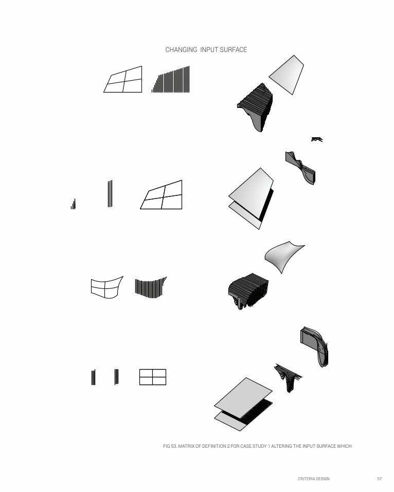
CRITERIA DESIGN 57
CHANGING INPUT SURFACE
FIG 53. MATRIX OF DEFINITION 2 FOR CASE STUDY 1 ALTERING THE INPUT SURFACE WHICH

58 CRITERIA DESIGN
I explored components that make up the two
grasshopper definitions provided for the case study,
testing the extent of their reach of the basic parameters
that define the number of segments and vector
coordinates that define the size and orientation of the
segments. I was then able to generate a more diverse
variety of outcomes when I manipulated the geometry of
the input surface and the image that defined the pattern
of undulation. Not having any particular goal in mind at
the time I pushed the definitions capabilities as far as I
could, generating some rather complex outcomes some
of which were successful and others which weren’t.
DESIGN CRITERIA
Out of the iterations I generated, I selected these
4 outcomes as the most successful. This is based
on a three-point design criteria I produced:
The Most Successful Iterations
1
3
The ability of the design to define a
usable space that permits (and possibly
also encourages) movement.
Maximal surface area exposed to sun so as to
enable maximal penetration of solar radiation if the
surface was made of or covered in solar panels.
It must be aesthetically pleasing, not
too busy and not too plain. It must
celebrate the curves of parametrics.
2
FIG 56. DESIGN GENERATED FROM DEFINITION 1
FIG 54. DESIGN GENERATED FROM DEFINITION 1
FIG 55. DESIGN GENERATED FROM ALTERING INPUT IMAGE IN DEFINITION 2
FIG 57. DESIGN GENERATED FROM ALTERING NPUT IMAGE IN DEFINITION 2

CRITERIA DESIGN 59
ANALYSIS OF THE RESULTS
Outcomes that were particularly unsuccessful
were those that produced overly complex and often
intersecting and overlapping sections. These designs
actively restricted movement through the space. Some
of the patterns of undulations produced were too
intense, with the variations changing too drastically
making them appear too busy and overpowering.
While others were too ordinary and uninspiring.
The two definitions produced different outcomes. The
first definition generated strips with a consistent defined
width, with their shape following that of the input
surface. The second definition produced sections that
extended from a flat plane, changing its width to produce
undulations according to the input pattern. The strips of
the first definition also moved horizontally according to
the relative location and shape of a reference line, while
the strips generated from the second definition occur at
regular set intervals regardless of the input geometry.
The 4 iterations I selected as the most successful are
those that not only have maximal surface area, thus
allowing them to generate the most solar energy if
composed of or covered with a solar energy generating
material, given the correct orientation, but also
produce an aesthetically pleasing way of defining
usable spaces through which people can move.
SPECULATIVE DESIGN POTENTIAL
Variations in the shape of the sections collectively
create the flowing and dynamic form of the undulating
surface. The outcomes produced from the first definition
could be applied in numerous ways. They could be
applied to flow along the ground plane, creating a sort
of maze of paths for people to walk through, or they
could create a ‘floating’ floor or ceiling plane, elevated
by the dips in the curvature of the sectional strips.
The products of the second definition though appear to
find the most logical application hanging upside down
as a ceiling with the sections running along the ceiling
to define the space below. The space would be confined
where the curves increase in size and opened where the
curves transition from thick to thin. Their application
as wall planes, running along the ground is much
more limited than the first definition, likely only being
used as ornament, partitions between lines, to divide
a space into uniform aisles, or as seats or tables. The
range of ways the geometry from the second definition
can be applied along the ground is extended by the
application of another material such as glass between
the sections to make the curving surface traversable.

60 CRITERIA DESIGN
B.3. Case Study 2.0: Swiss Re HQ
Introducing the Swiss Re Head Quarters
The Swiss Re HQ on 30 St Mary Axe by architect Ken Shuttleworth was architecturally, socially,
technically and spatially radical. Nicknamed ‘The Gherkin’, its 41 story’s are mixed use including
accommodation, offices and retail. The distinctive gherkin form responds to the site constraints
and is generated by the radial plan of the ground floor with a circular perimeter, which incrementally
increases, widening the building, and then start to decrease in size again towards the apex.
The first tall ecological building in London, it featured an energy efficient enclosure with a
continuous triangulated skin that permits light, views and a column-free floor plan. The buildings
profile not only maximized the public area on the ground level, but it also deflected less wind to
the ground than traditional rectilinear towers of similar sizes would. This created external pressure
differentials in the open ground floor spaces that in conjunction with opening panels, drives the
buildings natural ventilation system. This system was intended to enable the building to be more
sustainable, predicted to consume only half the energy that an air-conditioned tower would use.1
Although it does not fit within the traditional category of land art, I chose to use the Swiss Re as
my second case study as its unique form stands out against the typically rectilinear cityscape,
transcending its role from a mere building, to a large scaled piece of art. It diverts from the traditional
building geometries, favoring more unusual forms, with its curved form and a façade and skeleton
integrating a diagrid tessellation pattern composed of triangular and diamond shaped segments.2
I think that the Swiss Re has succeeded at its design intent of creating an iconic
building with a skeleton-like diagonally braced internal structure incorporated
within the light, continuous, triangulated glass skin with an energy conscious
agenda, and with the illusion of being unstable and gravity defying.
1 Isabelle Lomholt, ‘Swiss Re Building’, in e-architect, (July 30 2014) <http://www.e-architect.co.uk/london/swiss-re-building> [accessed 27 August 2014].
2 Ben Pell, ‘Stacked/Tiled’ in The Articulate Surface: Ornament and Technology in Contemporary Architecture (2010), accessed < http://books.google.com.au/books?id=4nfkr_0_xIsC&pg=PA159&lpg=PA159&dq=Swiss+re+tessellation&source=bl&ots=nINYNPrEXG&sig=4jE2HG3QVfguZZoxyJGOFYfTPAI&hl=en&sa=X&ei=VC4kVMiHCJegoQThyoGICw&ved=0CEEQ6AEwBQ#v=onepage&q=Swiss%20re%20tessellation&f=false>, p. 159.
FIG 58. SWISS RE DIAGRID GLASS SKIN AND STRUCTURE
FIG 59. GROUND LEVEL OF SWISS RE WITH OPENINGS IN THE DIAGRID GLASS SKIN, EXPOSING THE STRUCTURAL SKELETON TO ALLOW LIGHT AND AIR INTO THE BUILDING

http://www.fosterandpartners.com/media/Projects/1004/img1.jpg
CRITERIA DESIGN 61
FIG 58. SWISS RE DIAGRID GLASS SKIN AND STRUCTURE
FIG 59. GROUND LEVEL OF SWISS RE WITH OPENINGS IN THE DIAGRID GLASS SKIN, EXPOSING THE STRUCTURAL SKELETON TO ALLOW LIGHT AND AIR INTO THE BUILDING
FIG. 60 THE SWISS RE, WIDENING AT THE MIDDLE THEN TAPERING TOWARDS THE TOP

FIG 62. STARTING FROM SCRATCH AND CREATING CONE SHAPE AND CORRESPONDING FLOOR PLATES
62 CRITERIA DESIGN
FIG 61. ATTEMPT AT REVERSE ENGINEERING FLOOR PLATE OUTLINE THAT RESULTED IN A DEAD END
Reverse Engineering the Swiss Re Design

FIG 63. APPLYING A DIAGRID STRUCTURE COMPONENT TO THE CONE SHAPE
Baked 10 (U=20, V=10)Pipespipes with floorsPipes with surfaceBaked 10 (U=20, V=10)Pipespipes with floorsPipes with surface
FIG 64. ALTERING THE PARAMETERS OF THE DIAGRID STRUCTURE COMPONENT
CRITERIA DESIGN 63

64 CRITERIA DESIGN
FIG 65. RE-STARTING, AND ATTEMPTING TO CREATE A DIAGRID FROM SCRATCH,. SUBDIVIDED THE CONE SURFACE, SORTED IT AND CREATED A SPIRAL PATTERN. HIT A ROAD BLOCK WHEN TRYING TO CREATE A SPIRAL GOING IN THE OPPOSITE DIRECTION TO CREATE THE DIAGRID.

CRITERIA DESIGN 65
First final outcome
The pipes were divided up into small segments rather than as
smooth continual pipes that travelled up the structure.
I resolved this issue by removing the offset componment I
had used inbetween the pipe component and that used to
create the diagrid pattern across the structure as. I then
merged the resulting small pipe structures where they connect,
resulting in a smooth, continuous piped structure.
The Skeletal structure of the Swiss Re is not the external layer, but
is surrounded by a glass panel ‘skin’, with strips that vary in colour.
Offset the skin so that it was external to the frame.
Culled every second panel to create stripes.
Problem 1:
Problem 2:
Solution:
Solution:
Although relatively
rudimentary, this definition I
created is somewhat able to
emulate the diagrid pattern,
the iconic feature of the
Swiss Re. I came back to
this definition in week 8 and
revised it with a bit more
experience with grasshopper
under my belt, addressing
the problems and major
elements that were lacking
from this final product.
FIG 66. RENDERS OF MY FIRST FINAL OUTCOME, WITH THE SEGMENTED PIPED SKELETON ON THE EXTERIOR

66 CRITERIA DESIGN
Later Alterations to Final Outcome
FIG. 67 PROCESS OF FURTHER DEVELOPING THE DEFINITION USED FOR MY FIRST FINAL OUTCOME. APPLIED MATERIALITY. CREATED ALTERNATING STRIPS OF COLOURED PANELS WITH CULL
COMPONENT. APPLIED A SKIN WITH DIAGRID TESSELATION OVER THE DIAGONAL STRUCTURE
FIG. 68. PERSPECTIVES OF ALTERATIONS TO MY FINAL REENGINEERED DESIGN OF THE SWISS RE
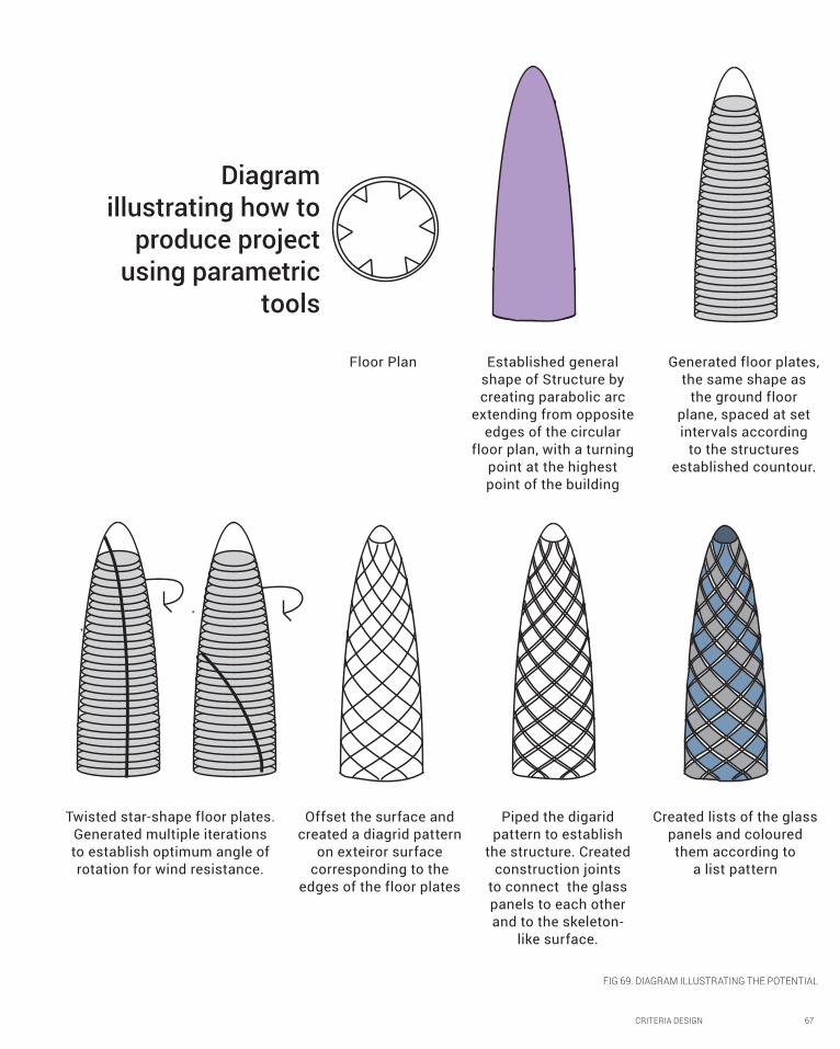
CRITERIA DESIGN 67
Diagram illustrating how to
produce project using parametric
tools
Floor Plan Established general
shape of Structure by
creating parabolic arc
extending from opposite
edges of the circular
floor plan, with a turning
point at the highest
point of the building
Generated floor plates,
the same shape as
the ground floor
plane, spaced at set
intervals according
to the structures
established countour.
Twisted star-shape floor plates.
Generated multiple iterations
to establish optimum angle of
rotation for wind resistance.
Offset the surface and
created a diagrid pattern
on exteiror surface
corresponding to the
edges of the floor plates
Piped the digarid
pattern to establish
the structure. Created
construction joints
to connect the glass
panels to each other
and to the skeleton-
like surface.
Created lists of the glass
panels and coloured
them according to
a list pattern
FIG 69. DIAGRAM ILLUSTRATING THE POTENTIAL

68 CRITERIA DESIGN
B.4. Technique Development with Case Study 2.0
SHAPE
DIAGRID
SPIRAL VECTORS
DIAMOND PANELS
DIAMOND FRAMES
SELECTIVE DIAMOND
FRAMES

CRITERIA DESIGN 69
FIG. 70 MATRIX OF ITERATIONS FURTHER EXPLORING AND TESTING THE LIMITS OF THE DEFINITION I PRODUCED WHEN REVERSE ENGINEERING THE SWISS RE
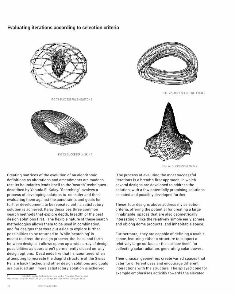
70 CRITERIA DESIGN
Evaluating iterations according to selection criteria
Creating matrices of the evolution of an algorithmic
definitions as alterations and amendments are made to
test its boundaries lends itself to the ‘search’ techniques
described by Yehuda E. Kalay. ‘Searching’ involves a
process of developing solutons to consider and then
evaluating them against the constraints and goals for
further development, to be repeated until a satisfactory
solution is achieved. Kalay describes three common
search methods that explore depth, breadth or the best
design solutions first. The flexible nature of these search
metholdogies allows them to be used in combination,
and for designs that were put aside to explore further
possibilities to be returned to. While ‘searching’ is
meant to direct the design process, the back and forth
between designs it allows opens up a wide array of design
possibilities as doors aren’t permanently closed on any
design options. Dead ends like that I encountered when
attempting to recreate the diagrid structure of the Swiss
Re, are back tracked and other design solutions and goals
are pursued until more satisfactory solution is acheived.1
1 Yehuda E. Kaylay, Architecture’s New Media: Principles, Theories and MEthods of Computer-Aided Design (Cambridge, MA: MIT PRess, 2004), pp. 18,19.
The process of evaluting the most successful
iterations is a breadth first approach, in which
several designs are developed to address the
solution, with a few potentially promising solutions
selected and possibly developed further.
These four designs above address my selection
criteria, offering the potential for creating a large
inhabitable spaces that are also geometrically
interesting unlike the relatively simple early sphere,
and oblong dome products. and inhabitable space.
Furthermore, they are capable of defining a usable
space, featuring either a structure to support a
relatively large surface or the surface itself, for
collecting solar radiation, generating solar power .
Their unusual geometries create varied spaces that
cater for different uses and encourage different
interactions with the structure. The splayed cone for
example emphasises activitiy towards the elevated
FIG 71 SUCCESSFUL SKELETON 1
FIG. 72 SUCCESSFUL SKELETON 2
FIG 73. SUCCESSFUL SKIN 1
FIG. 74. SUCCESSFUL SKIN 2

CRITERIA DESIGN 71
centre of the structure while the looped geometries
encourage circumabulation around a central point.
RECONSIDERING SELECTION CRITERIA
Reverse engineering the Swiss Re and its structural
skeleton and glass skin form have inspired me to
look for a design that is light and almost floating
and that has the potential to either allow or withold
light to create an atmosphere approriate for its
prescribed use. Two of the selected successes have
the potential to be ‘structural skeletons’, while the
other two could be an external ‘skin’ cladding.
FURTHER EXPLORATION
With these selected successes, I further explored
the tesselation approach employed with the Swiss
Re, and subdivided the surface with more patterns
and further explored the possible structural
geometries possible with these input shapes.
FIG 75. FURTHER EXPLORATION OF THE SELECTED SUCCESSFUL OUTCOMES
SUBDIVIDING THE TRIANGULAR PANELS
INTO SMALLER TRIANGLES

72 CRITERIA DESIGN
B.5. Technique: Prototype
FIG. 76 DEVELOPING THE SKIN WITH TRIANGULAR FRAMES:
FIG. 77 ATTEMPTS AT OFFSETTING THE REFERENCE SURFACE SO THAT THE PANELLED SKIN RESTS ONTOP OF THE STRUCTURAL SKELETON BELOW
Following on from the successful designs I isolated, I decided to further investigate the potential of the design
in figure 73, particularly its materialisation. I chose this particular geometry as its not only does large span
allows it to create a large enclosed and habitable space. Furthermore, its subtle gradation in height creates
a more intimate relationship between the structure and the ground it rests upon while barely touching,
almost as if its floating. For ease of construction and to increase the sturctural stability of the design, I
changed the tesselation pattern applied to the structure and the skin from diamonds to triangles.
Process of developing the materialisation of my design
Potential problems lie with constructing the tightly angled triangualr paneLs around the opening in the
middle of the design and the short but elongated panels. fabricating the design at 1:250 scale could
offer insight into whether this design can physically be achieved and how this might be done.

CRITERIA DESIGN 73
The skin and skeleton style of my design requires
consideraiton of how these two ‘layers’ interact with each
other as the structural skeleton holds up the large span
of the triangulated skin. Furthermore, the structure that
supports the skin needs to be able to withstand a large
load from the dead weight of the sturcture, and resist the
strong wind loads that the building will likely be subject
to due to its shape and location along the water front.
Constructing the skeletal structure
Therefore, at the nodes of the piped skeletal structure
which correspond to the corners of the frames on the
skin , I put a sphere and boolean split the pipes and
spheres, leaving holes in the spheres the location
and angle of which uniquely correspond to their
respective pipes. The sphere acts as a rigid joint,
providing structural stability to the skeleton, and also
provides the an extension of the structural surface
where the corners of the skin’s frames can connect to
it while still being offset from the skeletal structure.
FIG 78. SKELETAL STRUCTURE WITH RIGID SPHERE JOINTS AT NODES OF TRIANGLES FIG. 79. EXPLODED SECTION OF SKELETAL STRUCTURE,
DEMONSTRATING ITS POSSIBLE CONSTRUCTION TECHNIQUE
FIG. 80. SIDE AND FRONT PERSPECTIVES OF DESIGN SHOWING PANELLED SKIN RESTING ONTOP OF THESPHERES OF THE SKELETAL STRUCTURE

74 CRITERIA DESIGN
I construced my model by dividing the overall structure
into strips cut out on 200gsm white card, which join
together by laying over protruding tabs of the adjacent
strips. The structure is further subdivided into triangular
shaped frames formed by three connecting trapezoids,
which act as the structural component of the skin and
hold the triangular panels. This construction technique of
layering on the structure in sections could be translated
to the real life construction of the design. Dividing
up the structure into smaller parts could facilitate
a faster more efficient construction process as the
parts could be fabricated and constructed off-site.
This process of dividing up the structure reminds me of
the sectional material system methodology I explored
in Case Study 1, in which an overall form is establsihed
Constructing the skin
These connections would require further development
as they are currently only representational. I
attempted to generate a rudimentary joint that could
connect the pipes together, or to another surface
like the sphere, or possibly even connect the two
FIG. 81. ATTEMPT AT CREATING POSSIBLE JOINT BETWEEN PIPES OR SKELETON AND SKIN
FIG. 82. SKELETAL STRUCTURE (TOPI), TRIANGULAR PANEL SKIN (MIDDLE), HOW THEY FIT TOGETHER (BOTTOM)
FIG. 83. PHOTO OF WHITE PAPER CARD MODEL FROM TOP

CRITERIA DESIGN 75
by the culmulative effect of the relationship between
its consistuent parts. This methodology allows for a
faster, safer and more efficient construction as the parts
can be formed off-site, to be arranged on-site later. For
my design, the triangular frames, and possibly even the
strips could be assembled offiste, and then connected
to each other on-site to form the overall structure.
The detail model I fabricated of the triangular frame
of trapezoids tested how these trapezoids would
connect to each other to form the triangular frames.
I carefully arrayed tabs along select edges of the
trapezoids that the adjacent trapezoids would rest
ontop, allowing them to appear to almost join together
seamlessly once the tabs were glued down.
However, as the tabs I created were just rectangular
protrusions and not carefully shaped to correspond
to the shape of the adjacent trapezoids, I had to
manually adjust a few of the tabs so that they did
not stick out. Therefore, in the real life construction
of this design, the protrusions upon which each
adjacent strip would rest would be much more carefully
determined, and tailored to the receiving shape.
FIG. 84. THE ‘STRIPS’ THAT THE DESIGN WAS BROKEN DOWN INTO TO BE CUT FROM THE CARD CUTTER AND ASSEMBLED. COLOURED TO SHOW HOW THEY CULMULATIVELY FORM THE DESIGN FORM
FIG. 85. PHOTO OF DETAIL MODEL MADE OUT OF DIGITALLY CUT PIECES OF WHITE CARD FIG. 86. THE LOCATION OF THE DETAIL I WAS MODELLING

76 CRITERIA DESIGN
Testing the atmospheric lighting
28
26
25
31
3230
27
29
14
15
12
15
10
24
23
19
21
18
17
22
20
02
8
5
16
3 6
1
4
7
9 11
Constructing the model enabled me to see how light is able to penetrate
through the empty panels on the skin, and the manner in which it illuminates
the ground below. By making a physical model and photographed it,
it allowed me to see how light that the relatively arbritaray placement
of the culled panels didn’t provide a particualrly interesting aesthetic
quality. Furthermore, it allowed me to realize that the light cast on
the ground provided sharply defined areas of bright light, would not
be as effective at full scale. This lead me to decide to pursue an airy
atmosphere of filtered light that would cascade over the users.
FIG. 87 DIGITAL MODEL OF DETAIL AND ITS CONSTITUENT PARTS ANNOTATED WITH NUMBERS TO SHOW HOW THEY FIT TOGETHER
FIG. 88. CLOSE UP PHOTO OF MODEL SHOWING SHADOWS CASE ON GROUND BELOW (BOTTOM)FIG. 89. PERSPECTIVE PHOTO OF CARD MODEL (TOP)

CRITERIA DESIGN 77
FIG. 90 PHOTO OF CARD MODEL
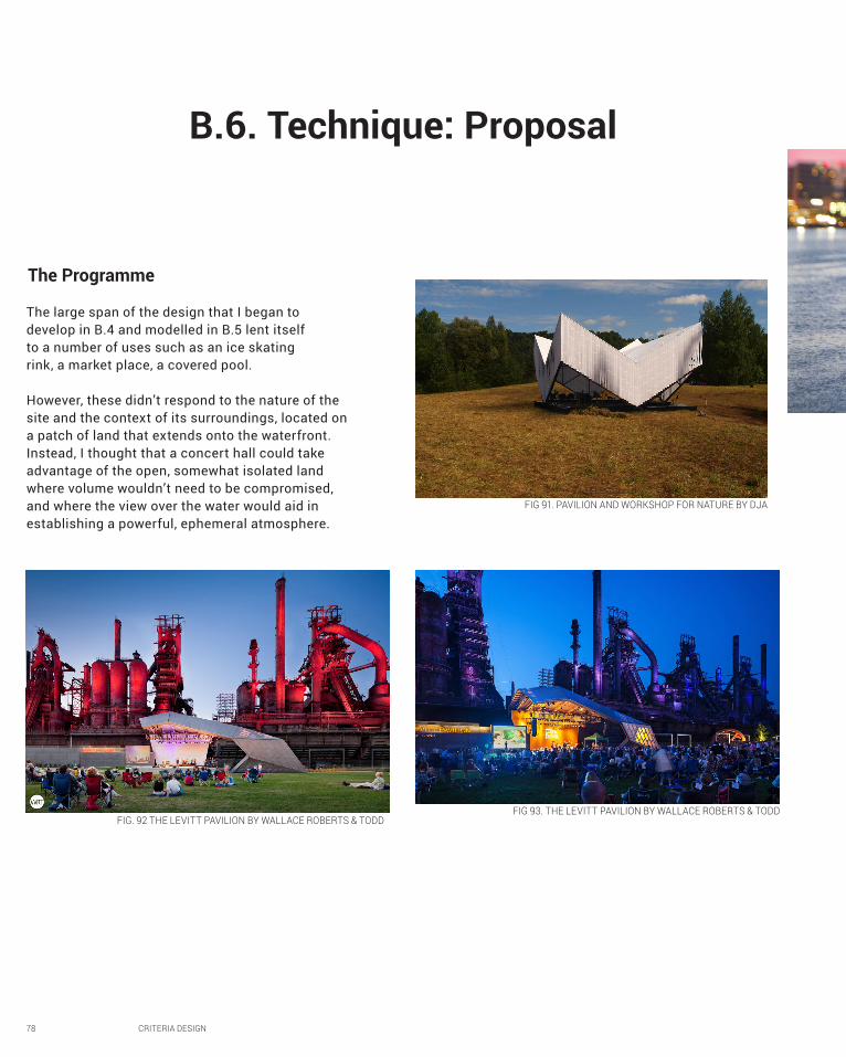
78 CRITERIA DESIGN
B.6. Technique: Proposal
The large span of the design that I began to
develop in B.4 and modelled in B.5 lent itself
to a number of uses such as an ice skating
rink, a market place, a covered pool.
However, these didn’t respond to the nature of the
site and the context of its surroundings, located on
a patch of land that extends onto the waterfront.
Instead, I thought that a concert hall could take
advantage of the open, somewhat isolated land
where volume wouldn’t need to be compromised,
and where the view over the water would aid in
establishing a powerful, ephemeral atmosphere.
FIG 91. PAVILION AND WORKSHOP FOR NATURE BY DJA
FIG. 92 THE LEVITT PAVILION BY WALLACE ROBERTS & TODD FIG 93. THE LEVITT PAVILION BY WALLACE ROBERTS & TODD
The Programme

CRITERIA DESIGN 79
FIG 94. PIER SIX PAVILION
Altering the overall shape
Altered the shape of the structure slightly to better
suit the intended programme of a pavilion for concerts,
manipulating the opening so that it drew focus towards
the elevated performance area situated underneath
the the hole in the middle of the structure.
Instead of having relatively arbitrarily culled panels on
the surface left open to permit light, I decided to further
direct attention to the stage by filling in the panels
behind it with a solid surface. The filled in panels act
as dark backdrop behind the stage while the angled
opening in the structures ceiling above the stage further
directs light onto the stage. The highlighted stage
contrasts with the filtered light over the audience.
Looking at case studies, most outdoor concert halls feature a covered, elevated stage and are surrounded
by large empty areas around them for people to casually gather in varied sizes, but that would be largely
unoccupied and empty for the majority of the time. The stage is arranged as the centre of attention,
with either a physical backdrop or a stark contrast to the surrounding environment, to enhance the
emphais of the lit stage during performance. While outdoor concert halls are often lit with artifical
lighting, the natural light permitted into the audience space, in concjunction with the connection with the
surrounding natural environment can evoke a powerful atmosphere, aiding the auditory experience.
FIG. 95. AERIAL RENDER OF NEW STRUCTURE FORM

80 CRITERIA DESIGN
Stairs and Seating
FIG. 96 DEVELOPING THE ARRANGEMENT, SPACING AND SCALE OF THE SEATS
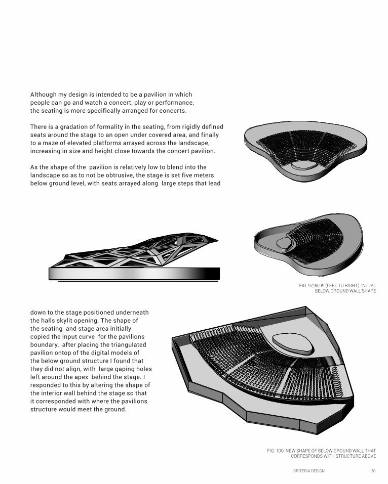
CRITERIA DESIGN 81
Although my design is intended to be a pavilion in which
people can go and watch a concert, play or performance,
the seating is more specifically arranged for concerts.
There is a gradation of formality in the seating, from rigidly defined
seats around the stage to an open under covered area, and finally
to a maze of elevated platforms arrayed across the landscape,
increasing in size and height close towards the concert pavilion.
As the shape of the pavilion is relatively low to blend into the
landscape so as to not be obtrusive, the stage is set five meters
below ground level, with seats arrayed along large steps that lead
down to the stage positioned underneath
the halls skylit opening. The shape of
the seating and stage area initially
copied the input curve for the pavilions
boundary, after placing the triangulated
pavilion ontop of the digital models of
the below ground structure I found that
they did not align, with large gaping holes
left around the apex behind the stage. I
responded to this by altering the shape of
the interior wall behind the stage so that
it corresponded with where the pavilions
structure would meet the ground.
FIG 97,98,99 (LEFT TO RIGHT): INITIAL BELOW GROUND WALL SHAPE
FIG. 100: NEW SHAPE OF BELOW GROUND WALL THAT CORRESPONDS WITH STRUCTURE ABOVE
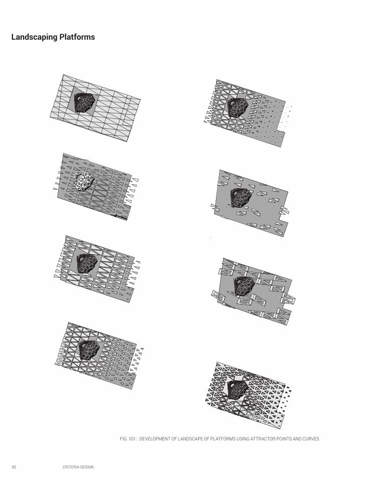
82 CRITERIA DESIGN
Landscaping Platforms
FIG. 101: : DEVELOPMENT OF LANDSCAPE OF PLATFORMS USING ATTRACTOR POINTS AND CURVES

CRITERIA DESIGN 83
In addition to the formal seating and the informal
covered area, I decided to array triangular platforms
across the land. The pattern that I decided on was
developed by using attractor points and curves
along the surface to increase the size and height
of the platforms towards the structure and create
a path that weaves through to the pavilion.
although the maze of platforms varies gradually
in height across the site, some of them rise
above eye level, and create areas somewhat
removed from the concentrated effect of the
concert experienced underneath the pavilion.
The platforms have an offset stone boundary, are
covered in either grass or wood, and serve as areas in
which people can sit and listen to the concert while not
necessarily facing the stage, and instead experiencing
it with the surrounding water front landscape. These
platforms also provide the space with another function
when there aren’t performances as they provide a sort
of man made park with areas for people to congregate,
have lunch, or just relax by the waterfront.
FIG. 102: INITIAL ATTEMPT AT DIFFERENTIATING THE USE OF THE TRIANGULAR PLATFORMS
FIG. 103: RENDERED PERSPECTIVE OF FINAL DESIGN FOR INTERIM PRESENTATION

84 CRITERIA DESIGN
The panels
Taking what I had learnt from the randomly culled panels of my physical model which produced large, harsh
areas of dramatic light, I decided to go back to a definition I had started to explore in my iterations, and
subdivide the trinagular panels into more triangles. I then used culling to select a number of the subdivided
glass panels and assign them different colours, which would filter light through to the audience, creating
an almost mystical, other worldly atmosphere enhancing the stereophonic experience within the pavilion.
This dramatic lighitng over the audience and the atmosphere it creates in ocnjunction with the concert
experience, is further emphasized by the panels behind the stage being filled in so as to exaggerate the
effect of the lighting on the stagefrom above and from lighting suspended from the steel skeleton.
All the glass panels arebuilding integrated photovoltaic solar panels that come in a variety of
colours, patterns, opacity and sizes. There is a space located beneath the seats where the
equipment for solar power generation, inaccessable by the public and out of site.
FIG. 104: VIEW OF THE PAVILIONS OPENING INTO THE BELOW GROUND SEATING AND STAGE AREA

CRITERIA DESIGN 85
FIG 105: CLOSE UP OF PAVILION OPENING
FIG. 106: PERSPECTIVE SHOWING TRIANGUALR LIGHTS

86 CRITERIA DESIGN
FIG. 107: ELEVATION FROM LEFT

CRITERIA DESIGN 87
FIG. 108: ELEVATION FROM RIGHT SHOWING GRADUAL INCREASE IN HEIGHT OF PLATFORMS

88 CRITERIA DESIGN

CRITERIA DESIGN 89
FIG. 109: FLOOR PLAN

90 CRITERIA DESIGN
B.7. Learning Objectives and Outcomes
The opportunity to provide an interim presentation,
although stressful, proved to be reassuring and much
more helpful than I had expected. Connections that I
hadn’t quite fully formed yet were brought to fruition
when the reviewers pointed them out, as another set
of more experienced eyes were capable of catching
things I hadn’t. This is particularly the case with the
feedback I got about the wide path leading towards the
pavilion being unneccessary as the spaces between the
elevated platforms not only are sufficient, but created
an added element of further interacting with the site
and the idea that one would have to weave through
them, lead by the sound and light eminating from the
stage. The suggesting to individualize the platforms
was another one that I had begun to think about, as I
had started to differentiate some of the platforms by
lining them with a grassed area instead of wood.
One piece of feedback that hadn’t even occured
to me before was making the skin an even lighter
structure. Before this was suggested I hadn’t realised
that the structure was actually relatively heavy,
unlike the airy, light, but gravity defying Swiss
Re which I had initally been emulating. I intend
to further explore how I could make the structure
lighter, possibly increasing the amount of glass, or
decreasing the amount of material all together.
Although tediuous, the process of creating dozens
of iterations, pushing the definition to its limits and
exploring its possibilities, helped me understand the
design advantages and opportunities made possible
by such generative design technologies which I
hadn’t fully appreciated when doing theoretical
reasearch in part A. Furthermore, it proved to be
much more helpful in developing my design proposal
than I had thought it would be, and I ended up going
using a triangular subdivision component that I had
briefly explored in a number of my iterations.
Although I was able to find some success in manipulating
the definition for case study 1, I really struggling coming
up with a definition from scratch for case study 2. This
is evident in my rather rudimentary initial final product
for reverse engineering the Swiss Re. However, after
struggling through with grasshopper, and following the
online videos, I was able to gain some more confidence
in my ability to model parametrically and went back
and attempted a secondary final reverse engineered
Swiss Re, utilizing the knowledge I had gained in
just a few short weeks to develop the design much
further than I had initially. This is not to say that I
have not struggled with establishing definitions since
then, but I have become more resourceful, looking up
online tutorials, rummaging through the grasshopper
files and experimenting with what I can produce.
I had been intending on carrying the solar power
generating feature through my entire design, and
had begun to think about incorporating it into the
platforms, but it seems to be proving to be a secondary
consideration and isn’t really driving the form of
my design at the moment. I’m not likely to try and
integrate it that much more into my design from
now on. However, if I do happen upon a particuarlly
interesting design solution I may re-integrate it
back as a more primary element of my design.

CRITERIA DESIGN 91
Part B Reference List
“BanQ / Office dA”. 03 Dec 2009. ArchDaily. <http://www.archdaily.com/?p=42581 >[accessed 06 September 2014]
Pell, Ben. ‘Stacked/Tiled’ in The Articulate Surface: Ornament and Technology in Contemporary Architecture (2010), accessed < http://books.google.com.au/books?id=4nfkr_0_xIsC&pg=PA159&lpg=PA159&dq=Swiss+re+tessellation&source=bl&ots=nINYNPrEXG&sig=4jE2HG3QVfguZZoxyJGOFYfTPAI&hl=en&sa=X&ei=VC4kVMiHCJegoQThyoGICw&ved=0CEEQ6AEwBQ#v=onepage&q=Swiss%20re%20tessellation&f=false>.
dECOi architects. ‘OneMain Street’. (2011), <http://www.decoi-architects.org/2011/10/onemain/> [accessed 28 August 2014].
Denton Corker Marshall, ‘Webb Bridge’, in The Australian Insitutte of Architects (2013) < http://dynamic.architecture.com.au/awards_search?option=showaward&entryno=20053006> [accessed 27 August 2014].
Iwamoto, Lisa, Digital Fabrications: Architectural and Material Techniques (New York, Princeton Architectural Press, N.D.) http://atc.berkeley.edu/201/readings/Iwamoto_Digital_Fabrications.pdf.
Kaylay, E. Yehuda. (2004) Architecture’s New Media: Principles, Theories and MEthods of Computer-Aided Design (Cambridge, MA: MIT PRess).
Lomholt, Isabelle ‘Swiss Re Building’, in e-architect, (July 30 2014) <http://www.e-architect.co.uk/london/swiss-re-building> [accessed 27 August 2014].
Marcos, Carlos L., ‘New Materiality: Digital Fabrication’ in: IMproVe 2011 – International Conference on Innovative Methods in Product, (2011).
Sokol, David ‘Banq’, Australian Design Review, (2009), <http://www.australiandesignreview.com/interiors/661-banq> [accessed 29 August 2014].

92 CRITERIA DESIGN
Part B Image ListFig. 33 Denton Corker Marshall, ‘ Webb Bridge’, photography, retrieved from http://www.
dentoncorkermarshall.com/projects/webb-bridge/ [accessed 27 August 2014]
Fig. 34 Instinia,’Web Bridge’, photograph, May 2013<,http://instinia.com/photography/architecture/webb-bridge/ >[accessed 31 august 2014].
Fig 35 ‘Inside Ronchamp Roof’, photograph, supplied by Carlos Zeballos, MY Modelskin Architecture, 2012,< http://
architecturalmoleskine.blogspot.com.au/2012_06_01_archive.html >[accessed 31 august 2014]
Fig 36 ‘Exterior of roof of Corbusier’s Ronchamp’, photograph supplied by Carlos Z eballos, MY Modelskin Architecture,
2012, <http://architecturalmoleskine.blogspot.com.au/2012_06_01_archive.html >[accessed 31 august 2014]
Fig 37 dECOi architects, ‘OneMain Street’, photograph, (2011), <http://www.decoi-
architects.org/2011/10/onemain/> [Accesseed 06 September 2014].
Fig 38 dECOi Architects, ‘One Main Street curved sections’, photograph, (2011), <https://acdn.architizer.com/
thumbnails-PRODUCTION/ba/da/badaeb2e33a4a86dad048d1192831ab2.jpg> [Accessed 06 September 2014]
Fig 39 dECOi architects, ‘OneMain Street’ photograph, (2011), <http://www.decoi-architects.org/2011/10/onemain/> [06 September 2014].
Fig 40 dECOi architects, ‘OneMain Street’ , photograph, (2011), <http://www.decoi-
architects.org/2011/10/onemain/> [accessed 06 September 2014].
Fig 41 dECOi Architects, ‘One Main Street interior roof and column’ photo by Anton Grassi/Esto
< http://www.cwkeller.com/proj_cat/commercial/> [Accessed 06 September 2014]
Fig 42 Horner, John. “BanQ / Office dA”, photograph, (2009). ArchDaily. <http://www.archdaily.com/?p=42581> [accessed 06 September 2014]
Fig 43 Horner, John. “BanQ / Office dA”, photograph, (2009). ArchDaily. <http://www.archdaily.com/?p=42581 >[accessed 06 September 2014]
Fig 44 Horner, John. “BanQ columns’, yatzer, (17 February 2009) photograph, http://www.
yatzer.com/BANQ-restaurant-by-Office-dA> [accessed 06 September 2014]
Fig 45 Horner, John. “BanQ / Office dA”, photograph, (2009). ArchDaily. <http://www.archdaily.com/?p=42581 >[accessed 06 September 2014]
Fig 46 Horner, John. “BanQ / Office dA”, photograph, (2009). ArchDaily. <http://www.archdaily.com/?p=42581 >[accessed 06 September 2014]
Fig 47 Horner, John. “BanQ / Office dA”, photograph, (2009). ArchDaily. <http://www.archdaily.com/?p=42581 >[accessed 06 September 2014]
Fig 48-57 Waring, Sarah, Rhino renders using Grasshopper, Studio Air, (2014).
Fig 58 Foster + Partners, ‘Diagrid glass skin’, Dimscale Blog, (8 February 2013), photograph, < http://dimscale.
blogspot.com.au/2013/02/architecture-references-foster-partners.html> [accessed 10 September 2014]
Fig. 59 Foster + Partners, ‘Swiss Re entrance, Dimscale Blog, (8 February 2013), photograph, < http://dimscale.
blogspot.com.au/2013/02/architecture-references-foster-partners.html> [accessed 10 September 2014]
Fig 60 Foster + Partners, ‘Swiss Re exteriror’, Foster and Partners website, photograph, http://www.
fosterandpartners.com/media/Projects/1004/img1.jpg [accessed 10 September 2014].
Fig. 61-90. Waring, Sarah, Rhino renders using Grasshopper, Studio Air, (2014).
Fig 91 Sveisbergs, Ernests. ‘Pavilion and workshop for Nature concert Hall by DJA’, Archdaily (17 August 2014), photograph,
http://www.archdaily.com/537479/pavilion-and-workshops-for-nature-concert-hall-dja/53ebfeb9c07a80388e0002a4_pavilion-
and-workshops-for-nature-concert-hall-dja_02_nature_concert_hall-jpg/> [accessed 15 September 2014]
Fig. 92. Totaro, Jeffrey, ‘Levitt Pavilion’, Archdaily (16 June 2014), photograph, <http://www.archdaily.com/515902/
the-levitt-pavilion-wrt-wallace-roberts-and-todd/Fig94 > [accessed 15 September 2014]
Fig 93. Totaro, Jeffrey, ‘Levitt Pavilion at night’, Archdaily (16 June 2014), photograph, <http://www.archdaily.com/515902/
the-levitt-pavilion-wrt-wallace-roberts-and-todd/Fig94 > [accessed 15 September 2014]
Fig. 94‘ Pier Six Pavilion’,< http://ramsheadgroup.ticketfly.com/files/2013/09/PierSix_web.jpg> [accessed 15 September 2014].
Fig. 95-109 Waring, Sarah, Rhino renders using Grasshopper, Studio Air, (2014).

CRITERIA DESIGN 93

94 CRITERIA DESIGN
B.8. Appendix: Algorithmic Sketches

CRITERIA DESIGN 95
FIG. 110: GRASSHOPPER DEFINITION FOR ‘SKIN’ OF DESIGN AND ARRANGEMENT OF TRIANGULAR PLATFORMS

96 PROJECT PROPOSAL
PART C: DETAILED DESIGN

PROJECT PROPOSAL 97
FIG 110. (LEFT) RENDERED TECTONIC UNIT DEVELOPED IN C.2.FIG 111. (RIGHT) RENDERED DETAIL OF GLASS
FRAMING UNIT DEVELOPED IN C.2

FIG 112. EXPLORATION OF SIZE OF PANELS AND SPAN OF MEMBERS TO MAKE DESIGN MORE STRUCTURALLY FEASABLE BY REDUCING LOAD CARRIED BY EACH MEMBER
98 PROJECT PROPOSAL
C.1. Design Concept
To be more adventurous in the algorithmic techniques I employed, particularly regarding the
patterning and panelling.
Reduce the proportion of steel forming the frame for the glass on the skin layer to make the
design appear delicate, lighter and less imposing as I had intend.
Consider the span of the structural elements and their relative size, to make them more
realistically be capable of accommodating the large load from the cantilevered opening.
Further develop the sphere based joint system to utilize the parametric capabilities of
grasshopper.
The feedback I
received from
my interim
presentation
was as follows:
I addressed these suggestions in three main stages of exploration and development, as detailed in the following pages.
Addressing feedback & amending the design
1) PANEL SIZE AND SKELETON SPAN
I reduced the span of the skeletal support
members and the size of the panels by altering
the number of divisions in the U and V directions,
exploring the different aesthetic and geometric
outcomes. In some variations, increasing the
divisions too much produced panels of sizes
and angles too small to be developable and
which created a very jagged appearance.
I redrew the structure
input curves to reorient the
‘seam’ where the triangular
panels meet from the centre
of the overhang, to the
area behind the stage.

PROJECT PROPOSAL 99
2) MORE DEVELOPED/SOPHISTICATED JOINERY SYSTEM
Following on from my rudimentary design
of a spherical joint system, I used the piping
command to join the end segments of
skeletal beam members that shared a node,
to form a tectonic system of intersecting
steel pipe joint units custom moulded to
accommodate the unique angle of the
respective skeletal pipes and skin beams. FIG. 113. RENDER OF PIPE JOINERY SYSTEM IMPLEMENTED THROUGHT
WHOLE STRUCTURE OF DESIGN BY UTILIZING ALGORITHM
FIG. 114. (ABOVE) CLOSE UP OF PORTION OF STRUCTUREFIG 115. (RIGHT) DIFFERENT PERSPECTIVES OF JOINT OF PIPES CORRESPONDING
TO MEMBERS THAT SHARE A POINT OF CONNECTION WITH THE VERTICAL PIPE ELEMENT WHICH JOINS THE SKELETAL SUPPORT LAYER TO THE SKIN LAYER

100 PROJECT PROPOSAL
PATTERNING TRIANGULATED GLASS PANELS
Smaller than 32m
Culled panels according to the relative distance
from their centers to reference
points on side. Larger than 32m
Selected items 3 & 4 from list
Culled sub -triangles 3 & 4
Light side panels
Dark middle panels
3) MORE SOPHISTICATED AND INTERESTING PATTERNING SYSTEM THAT INTEGRATES COLOUR
I developed my patterning algorithm further, exploring the various patterns generated by selecting items from the
list of panels, culling them and forming subset lists, and culling panels according to the distance from their centre
to points around the amphitheatre structure.
1 2 3
4 5 6
FIG 117. CULL PATTERNING ALGORITHM USED TO GENERATE COLOURED PATTERN IN FINAL DESIGN

PROJECT PROPOSAL 101
After this exploration, I developed the final pattern from a combination of variations that I concluded were
the most successful:
FIG 116. FINAL COLOURED GLASS PANEL PATTERN
7
8
1: Culled panels at a distance smaller than 31m from the back of the stage. Assigned a dark blue-
black colour and minimal transparency to create a dark backdrop behind the stage.
6: Retrieved panel items 3 & 4 from each subdivided triangular unit. Assigned dark blue colour and
high transparency. Culled items the same 3&4 items and assigned light blue and high transparency.
8: Culled panels according to the distance from their centres to points located on either side of
amphitheatre. Coloured light blue and highly transparent so users in surrounding area can see the
concert area within through the side glass panels.
The different hues of the panels will cast a soft blue light on the stage and seats below that varies in
intensity and hue in accordance with the transparency and hue of the panels above.
FIG. 115. FURTHER EXPLORATION OF CULL PATTERNING ALGORITHMS THAT LEAD TO FINAL DESIGN

102 PROJECT PROPOSAL
FIG 118. RENDERED PERSPECTIVE OF PATTERNING OF THE GLASS PANELS WITH DIFFERENT HUES OF
BLUE FROM THE BACK OF THE AMPHITHEATRE

PROJECT PROPOSAL 103

104 PROJECT PROPOSAL
The site at Refshaleoeon in Cophenhagen is
surrounded by industrial buildings and piers. Its
relative isolation from residential and commercial
buildings makes it a prime location for housing a large
amphitheatre that will likely generate a lot of sound.
The low and gradual but powerful shell-like shape
of the amphitheatre structure is reminiscent of
a wave rolling off the water and crashing onto
the land. The structures orientation so that it
opens up onto the site and the blue colouring
of the glazing adds to the symbolic imagery
The amphitheatre is oriented so that it faces the
main access points to the site: the water taxi
and the footpaths along the Sonder Hoved pier.1
This enables users to weave their way through
the maze of triangular platforms of varying
heights straight towards the concert hall.
1 Robert Ferry and Elizabeth Monoian, ‘LAGI 2014 Design Guidelines’, pp. 5 <http://landartgenerator.org/designcomp/>
CONSIDERING THE CONTEXT:
Revisiting the Brief & Finalizing the design concept
FIG 119.AERIAL VIEW OF AMPHITHEATRE AND LANDSCAPING DESIGN INSTALLED ON
REFSHALEOEON SITE IN COPENHAGEN
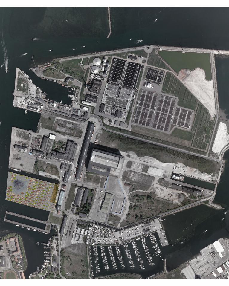
PROJECT PROPOSAL 105

106 PROJECT PROPOSAL
The reasons for the amphitheatre structure’s location in the upper western corner of the site is four-fold:
1) To maximise the ability of users lounging on the triangular platforms to view the concert
2) To provide the users on the triangular platforms with a view of the surrounding waterfront environment so that it may
enhance their experience of the concert, or provide places to view the waterfront landscape of the old shipyard when there is
no concert on.
3)To maximise the number of audience members.
4) To provide some areas that don’t face the amphitheatre opening from which one would embrace the auditory experience
in the emotive atmosphere created by the light effects coming through the panelled glass working in conjunction with the
surrounding water-front environment.
FIG 120. PANORAMIC VIEW FROM SITE LOOKING AT SITE, SURROUNDING PIER, AND WATERFRONT
FIG 121. PANORAMIC VIEW FROM SITE OF WATERFRONT

66m
80m
PROJECT PROPOSAL 107
2) To provide the users on the triangular platforms with a view of the surrounding waterfront environment so that it may
enhance their experience of the concert, or provide places to view the waterfront landscape of the old shipyard when there is
4) To provide some areas that don’t face the amphitheatre opening from which one would embrace the auditory experience
in the emotive atmosphere created by the light effects coming through the panelled glass working in conjunction with the
FIG 120. PANORAMIC VIEW FROM SITE LOOKING AT SITE, SURROUNDING PIER, AND WATERFRONT
FIG 121. PANORAMIC VIEW FROM SITE OF WATERFRONT
6.3m
154.63m
236.87
3.5m
FIG 122. (ABOVE) CLOSE UP AERIAL VIEW OF AMPHITHEATRE AND LANDSCAPING PLATFORMS ON SITE SHOWING ACCESS PATHS AND KEY DIMENSIONS OF SITE AND DESIGNFIG 123. (BELOW) VECTOR-LINE SECTION THROUGH DESIGN WITH HEIGHT DIMENSIONS

108 PROJECT PROPOSAL
FIG. 124 AERIAL PERSPECTIVE OF DESIGN INTEGRATED INTO SITE SHOWING ITS INTERACTION WITH THE SURROUNDING ENVIRONMENT

PROJECT PROPOSAL 109

110 PROJECT PROPOSAL
The triangular platforms are arrayed across the site, gaining in size as they near the wave-like amphitheatre structure. Their function is four fold:
-3.5m
0m0.5m1.0m
1.5m
0m0.5m
1.0m1.5m
1.7m
1) The platforms serve as seats from which people can watch the concert. For this purpose, their height increases proportionally as their distance from the amphitheatre increases to provide individuals further back from the structure with a higher vantage point so that they may see the concert. With the tallest platform reaching 1700mm, their height however is not so great that the cantilevered opening obstructs their view.
2) Platforms provide a different setting from which people can experience and appreciate the concert, immersed in the calm environment of the waterfront surrounding. For this purpose the array of platforms extends to the edge of the site to provide the concert with
3) They provide the site with a secondary function when there is no performance or concert on as people can gather there to hang out, have lunch or read on the grass or the timber topped platforms with a view of the waterfront.
4) They lead the users through the site along the maze-like paths between platforms (Fig. 130). This maze-like quality is especially aimed for children whose views of the amphitheatre from the ground would be obstructed by the taller platforms due to their shorter height. The users would weave through the platforms on a path of discovery following the sound and light from the amphitheatre.
TRIANGULAR PLATFORM
LANDSCAPING
FIG 125. AERIAL PLAN OF DESIGN WITH CONTOURS SHOWING THE ‘LANDSCAPE’ ELEVATION AS THE HEIGHT OF THE PLATFORMS CHANGES
FIG 126. (RIGHT) RENDER OF DESIGN DEPICTING LIGHT SHINING FROM WITHIN THE AMPHITHEATRE OUT TO THE SURROUNDING
LANDSCAPE CREATING A MYSTICAL ATMOSPHERE AT NIGHTFIG 127. (PAGE 110-111) RENDERED INTERIOR VIEW OF AMPHITHEATRE DEPICTING THE MYSTICAL ENVIRONMENT CREATED WHEN THE LIGHT SHINES THROUGH THE
PANELS OF DIFFERENT HUES OF BLUE AND THE ATMOSPHERE THIS CREATES WHEN IN CONJUNCTION WITH THE EMOTIVE EFFECT OF THE MUSIC FROM A CONCERT
FIG. 128. (PAGE 112-113) RENDERED LOW-ANGLE PERSPECTIVE OF AMPHITHEATRE AGAINST WATERFRONT BACKDROP
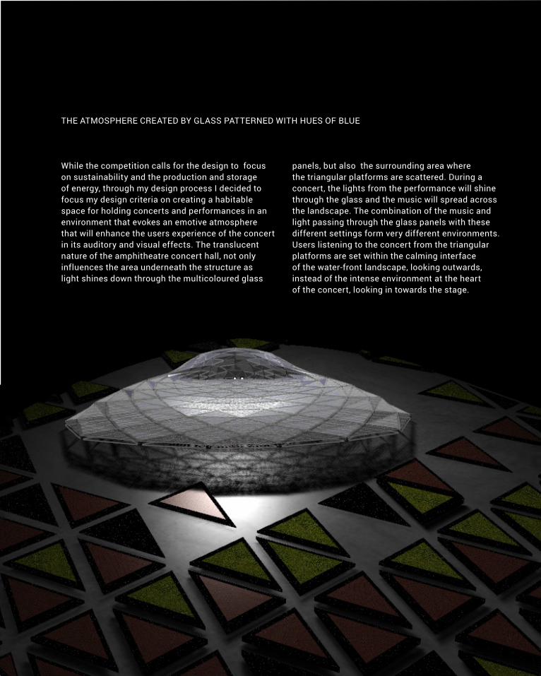
PROJECT PROPOSAL 111
THE ATMOSPHERE CREATED BY GLASS PATTERNED WITH HUES OF BLUE
While the competition calls for the design to focus
on sustainability and the production and storage
of energy, through my design process I decided to
focus my design criteria on creating a habitable
space for holding concerts and performances in an
environment that evokes an emotive atmosphere
that will enhance the users experience of the concert
in its auditory and visual effects. The translucent
nature of the amphitheatre concert hall, not only
influences the area underneath the structure as
light shines down through the multicoloured glass
panels, but also the surrounding area where
the triangular platforms are scattered. During a
concert, the lights from the performance will shine
through the glass and the music will spread across
the landscape. The combination of the music and
light passing through the glass panels with these
different settings form very different environments.
Users listening to the concert from the triangular
platforms are set within the calming interface
of the water-front landscape, looking outwards,
instead of the intense environment at the heart
of the concert, looking in towards the stage.

112 PROJECT PROPOSAL

PROJECT PROPOSAL 113

114 PROJECT PROPOSAL

PROJECT PROPOSAL 115

116 PROJECT PROPOSAL

PROJECT PROPOSAL 117
FIG 129. PERSPECTIVE OF THE BACK OF THE AMPHITHEATRE FROM A VANTAGE POINT ELEVATED ABOVE THE WATER. DEPICTS THE PATTERNING OF DIFFERENT HUES OF BLUE IN THE TRIANGULATED GLASS PANEL SYSTEM
FIG 130. (PAGE 116-117) RENDERED PERSPECTIVE OF MAZE-LIKE EFFECT OF THE ELEVATED TRIANGULAR PLATFORMS

118 PROJECT PROPOSAL

PROJECT PROPOSAL 119

FIG 131. DIAGRAM OF ALGORITHMIC TECHNIQUE I DEVELOPED USING GRASSHOPPER THAT
PRODUCE THE MAIN BEAM AND PIPE COMPONENTS THAT FORM THE STRUCTURES
SKIN FRAME AND SKELETON STRUCTURE
Referenced curves
Loft
Triangular pattern on
surfaceU = 12V = 30
TRIANGULAR GLASS
PANELS
Divided into trapezoidal
frame around a triangular panel
surface
TRAPEZOID GLASS FRAME
PANEL
SKIN
SKELETONMoved
triangular paneled
surface down 800mm in z
axis
Extracted panel wire
curves
Extended -590mm on
both ends of C8 curves
Extracted node points that various curves share
Exploded panels into
separate curve segments.
C8
120 PROJECT PROPOSAL
Algorithmic technique for skin and skeleton system

Culled panels according to
distance from their centers to a relative point at the center of the
structure
Subdivided culled panels into smaller
‘sub’ triangles
Smaller than 31m
Extruded & moved
90mm in Z axis
Retrieved brep wire
outline
Retrieved frames interior triangular shaped brep wire
outlines
Retrieved interior edge curves of
frames that divides them into trapezoids
Shortened curves by extending
ends by -5mm and -126mm Extruded
curves 90mm in z
axis
Retrieved frames exterior triangular shaped brep wire
outlines
C2
C1
C4
C3
Skin frame
Frame for subdivided
triangles
Dark panels around stage
Larger than 31
Skeletal Beams
Created line segment starting at
node points extending 800mm vertically . Length= distance between
the paneled surfaces
Divided curves into
points 590mm
apart
Retrieved & created line
between end and first points
Piped with 120mm radius and flat capped ends
Extended line by 100mm at
top and by 150 at bottom
Piped with 120mm radius
and flat capped ends
Shortened curves by 120mm from
node point
Extruded 1/2 x pipe radius in positive
and negative z direction
Vertical Pipe
‘Bones’
C9
PROJECT PROPOSAL 121

FIG 132. (ABOVE) DIAGRAM OF ALGORITHMIC TECHNIQUE I
DEVELOPED USING GRASSHOPPER THAT PRODUCES THE
TRIANGULAR LANDSCAPING PLATFORMS, THE STAGE AND THE SEATS ARRAYED ALONG
CORRESPONDING STAIRS
FIG 133. (BELOW) SECTION ALONG SHORT LENGTH OF SITE
THROUGH THE TRIANGULAR PLATFORMS SHOWING THEIR
SUBTLE CHANGE IN ELEVATION
122 PROJECT PROPOSAL
Algorithmic technique for triangular platform
landscaping, stage and stairs
TRIANGULAR LANDSCAPING
PLATFORMS
Referenced site
boundary curve
Divided surface into triangular
panels. U=12V=18
Retrieved nodes shared by adjacent
panels
Offset curve by distance
from referenced point /60
Created planar surface
from curve boundary
Created planar surface
from curve boundary
Solved for center point
Distance to closest point on curves to referenced
curveExtruded triangles in
z direction according to their relative distance
from reference curve
EXTRUDING THE PLATFORMS TO
VARIED HEIGHTS RELATIVE TO THEIR
DISTANCE FROM CURVE
STAIRS
STAGE Referenced smaller closed
curve of opening
Projected curve in Z
direction onto XY plane
Move down 2000mm in z
direction
Created planar surface
from curve boundary
Referenced curve
Created linear array curve, with 10 elements, at
1000mm intervals in Y
direction
Used array list length to determine
number of values/count fors series of numbers with 250mm step
Simplified and
grafted series of numbers
Grafted & simplified list
tree
Moved curves
according to series

PROJECT PROPOSAL 123
Grouped node
curves
Node point
Culled curves further than
53m
Distance between node point and
point in middle of pavilion structure
Culled triangles with distance
smaller than164m
Extruded triangles in
according to their
from reference curve
Scaled geometry
by 0.75
Move to XY Plane
Solved for center point
Moved 350mm in z
direction
Culled list according to
true/false pattern
Culled list according to
reversed true/false
patternExtrude brep
1000mm up and 1500mm down in Z
direction
Extend curves by
1000mm on both ends
Extruded 1000mm in Y direction and down 250mm in Z direction
to form stairs
Moved curves down 500mm in Z
direction
Generated 55 equally spaced,
and aligned plane frames along
curves
Created box on curve frames, 500mm in X,Y
and Z direction Culled every 14th
Culled item 0, the first box on the
curve
Moved curves down 500mm in Z
direction
Generated 55 equally spaced,
and aligned plane frames along curves
Created box on curve frames, 500mm in X,Y
and Z direction
Culled every 14th
Culled item 0, the first box on the
curve
Flat seats
Stairs
Stage centered below & following outline of
opening
Seats on
stairs
Timber platforms
Grass platforms
1000
250
Extruded platforms

124 PROJECT PROPOSAL
Preliminary construction process
FABRICATION
Cut triangular and trapezoid glass panels according to digital model specifications
192 x dark trianglular panels964 x dark blue middle triangular panels 718 x lighter blue middle triangular panels360 x random green triangular panels838 x light blue side panels474 x clear trapezoidal glass ‘frame’ panel
Steel vertical pipe columns. Standard size throughout design.
Custom steel pipe joints. Protruding pipes at specific, unique angles and a radius
greater than that of skeletal beams.
Custom length poles and skin frame beams. Can be modified onsite if required.
Produce: TRANSPORTED to site by trucks
Ground excavated & concrete poured.
Skeletal system erected: horizontal skeletal steel pipes inserted into corresponding
larger pipe protrusions of custom joints. Fastened with
bolts.
Steel beams of ‘skin’ frame slotted into sides of the vertical
extension of the piped joints.
Glazing panels connected to steel beam frame with sealant.
Stones laid for triangular platforms. Center filled with soil and covered in grass or timber
planks.
ASSEMBLY
FIG 135. (LEFT AND MIDDLE) DIAGRAMS OF EXPLODED PIPE JOINT CONNECTION TO DEMONSTRATE HOW THE SKELETAL PIPES WOULD SLOT INTO THEIR RESPECTIVE PLACE IN THE JOINT TO FORM TRIANGLES WITH UNIQUE, PREDETERMINED ANGLES
FIG 136. (RIGHT) ENVISAGED SLOTTED CONNECTION OF SKIN FRAME TO VERTIAL PIPE WITH EXTENSIONS FROM THE BEAMS SLOTTING THROUGH CAREFULLY PLACED HOLES IN THE VERTICAL PIPE THAT CORRESPOND TO THE ANGLE OF THE BEAM.
FIG 134. ENVISAGED CONSTRUCTION PROCESS OF PIPE JOINERY SYSTEM DEVELOPED FOLLOWING FEEDBACK FROM INTERIM PRESENTATION. NOTE: FURTHER DEVELOPED FOLLOWING MORE SOPHISTIATED AND FULLY RESOLVED TECTONIC SYSTEM DEVELOPED IN C.2

PROJECT PROPOSAL 125
C.2. Tectonic Elements & Prototypes
FIG. 137 PERSPECTIVE DIAGRAM OF RENDERED CORE TRIANGULAR CONSTRUCTION UNIT FROM ABOVE
In C.1 I had been exploring a tectonic system of
intersecting custom moulded steel pipes joints units.
After further consideration however, I came to realize
that the design of this tectonic system was likely to
be inefficient, costly due to their custom nature, and
incapable of providing any flexibility in the construction
process if necessary. Furthermore, the connection
of the vertical pipe element to the skin beams had
yet to be fully resolved as I had been envisaging.
To improve the flexibility and efficiency I employed
the use of fin plates, a form of simple pin connection
panels used to connect steel beams and columns. 1
1 ‘Simple connections’, SteelConstruction.info, http://www.steelconstruction.info/Simple_connections#Beam-to-beam_and_beam-to-column_connections [accessed 10 October 2014].
The structural skeletal system of horizontal steel pipes
or ‘bones’ supports the thin and minimal ‘skin’ layer of
beams above which house the glazing system. These
two layers are connected by the vertical steel pipe,
standard in size across the design. Unique angles of
the beams and pipes are achieved more efficiently by
using the standardized vertical pipe in conjunction with
fin plates. The edges of these fin plates correspond
to the angle of their connecting components and can
be easily modified during construction if necessary,
prior to being welded to the vertical pipe.

126 PROJECT PROPOSAL
FIG 138. EXPLODED PERSPECTIVE DIAGRAM OF RENDERED CORE TRIANGULAR CONSTRUCTION UNIT THAT REPEATS THROUGHT AMPHITHEATRE
Although this new joinery system is still customized to the angle of the adjoining pipes and beams, it is much easier to manufacture these smaller individual fins and elements with minute variations that are much more flexible to apply due to the ease in which they can be modified on-site if required.
While reducing the tectonic system down to a greater number of components translates to a somewhat
fiddly construction process, this can be mitigated by following the designations provided according to the digital model. Furthermore, slightly increasing the number of elements also enables the design to be more maintenance friendly, as damaged components like the fins, glass panels, and top plate of glazing frame unit can be removed and replaced without having to manufacture the whole joinery unit again.
TRAPEZOIDAL CLEAR GLASS
FRAME PANELS
SKIN FRAME BEAMS AND
GLAZING FRAME UNIT
VERTICAL PIPE JOINT
SKELETON PIPES AND BEAMS
INDIVIDUAL COLOURED
GLASS PANELS

PROJECT PROPOSAL 127
FIN PLATES
SKELETON BEAMS
SKELETON PIPES
FRAME PLUG
GLAZING FRAMING UNITSKIN FRAME BEAMS
SCREW/ BOLT HOLES
VERTICAL STEEL COLUMN PIPE
FIG 139. JOINT COMPONENT WITH MEMBERS LABELLED
FIN PLATES
FIG 140. JOINT COMPONENT WITH PLUG AND PLATES LABELLED

128 PROJECT PROPOSAL
I decided to implement a simple pin
connection system that utilizes fin plates or
‘fins’ to connect the skin and skeleton beam
members to adjacent members, the joinery
unit and the skeletal beam to their respective
pipes, due to the following reasons:
The fin plates are welded to the pipe members
off-site, and then bolted to the members
on-site at angles corresponding to the
specifications in the digital model.
These fin plate element can be replicated across the
design, set at angles specific to the angle of their
connecting members, relatively easily by utilizing
algorithmic techniques. Modelling and calculating
the angles of such a tectonic system using a non
algorithmic method such drawing or solely using
CAD would by very difficult and laborious.
FIG 141. DIAGRAM OF FIN PLATE CONNECTIONS TO BEAMS
FINS
A) They are capable of accepting loads
and rotation, resisting possible uplift
and additional load from the cantilevered
opening, without adversely affecting
the members structural integrity.
B) They are simple and quick to erect
and are economical to fabricate.
C) Their application on only one side of the
adjoining member reduces the occurrence
of intersecting bolts where the angle
between fins is small, which is much
higher with two-sided connections.1 1 ‘Simple connections’, SteelConstruction.info, http://www.steelconstruction.info/Simple_connections#Beam-to-beam_and_beam-to-column_connections [accessed 10 October 2014].
The vertical pipes along the edges of the
structure just offset from the below-ground
wall, that intersect the ground plane are
connected to a the ground as steel posts.
The end of the pipe is welded to a 35mm
thick square steel base plate 150mm x
150mm which is bolted to a 70mm thick
225mm x 225mm concrete base which
connects to the reinforced counterweights
installed in the concrete ground below.
CONNECTION TO GROUND
FIG 142. RENDERED PERSPECTIVE OF CONNECTION TO VERTICAL PIPE TO GROUND BY BEING WELDED TO
STEEL BASE PLATE BOLTED TO CONCRETE BASE

PROJECT PROPOSAL 129
FIG 143. EXPLODED RENDER DIAGRAM OF MAIN CONSTRUCTION JOINT
TOP PLATE
PLUG AND
T-SHAPED
BOTTOM PLATE
GLAZING
FRAME
UNIT
FINS

130 PROJECT PROPOSAL
GLAZING FRAME UNIT
In refining my tectonic design I explored the manner
in which the glass panel facade could be secured and
affixed to the rest of the structural system while retaining
the strong skeleton and skin design I began exploring with
my reverse engineering of the Swiss Re. Initially I was
considering implementing a point-clamp ‘spider glass’
system typically used for curtain walls that elevated the
glazing system with small protruding clamp elements with
circular components at the tips that connect to the glass
panel. However, I decided not to pursue this system as
one would logically remove the skin framing layer when
implementing such a design, as the small protruding
elements could directly join to the skeletal support.
FIG 144. POINT CLAMP ‘SPIDERGLASS’ GLAZING SYSTEM
However I decided against this system as the reduced
space between the skeleton and the glazing would
make the skeleton pipes, which are relatively thick
to support their large span, more visible from the
structures exterior. To support the loads and span of the
structure, the skeletal pipes are thicker than the skin
frame that supports the glazing. Setting the skeleton
further back from the glazing, enables the structure to
appear ‘lighter’ due to the reduced visible weight. This
is evident in the comparison between my design for
B.6 (fig.103-109 ) and my current design (fig.124 & 129)
which appears notably lighter as the amount of steel that
constitutes the skin frame and the amount of visible
steel material overall has been largely reduced.
Furthermore, such a system would face the same
problem as my previous preliminary tectonic
system, in that each unit would need to be custom
moulded and fabricated in its entirety to account
for the angles, size and spacing of the panels
of this type of system would also prove not
only highly laborious as each component would
need to be custom fabricated to suit the angle
at which adjoining glass panels connected, but
also problematic as the panels vary in size and
shape. The small corners of the smaller panels
would make it difficult to place the end cups
without resorting to adhering them in the centre
of the panel which would disrupt the aesthetics.
FIG 145. GLAZING FRAME UNIT INSPIRATION: CURTAIN WALL GLAZING SYSTEM

PROJECT PROPOSAL 131
Although the skeletal pipes are still visible in
the new tectonic system, they offset from the
skin layer by over 800mm, and are partially
hidden by the thin plates of the glazing frame
unit that connect to the T-shaped bottom
plate on-top of the skin frame beams.
Instead, I drew inspiration from adapting the
standard non-load bearing glazing frame
unit for curtain walls wherein the glass
panel is enclosed between an inner and
outer frame plates or ‘mullions’ separated
by a smaller element set back to create
a slot for the glazing. The design would
be installed using a combination of stick
and unitized systems, with the smaller
triangular units composed off-site, and the
larger units connected piece by piece. 1
The glazing unit connects to the top end
of the vertical pipe joint via a cylindrical
‘plug’ that protrudes down from the glazing
frame bottom plate and has a diameter
smaller than that of the vertical pipe. The
glazing system would be waterproofed by
the implementation of sealant where the
glass panels connect to the glazing frame
and along the sides of the plug to stop
water dripping onto the audience below.1 Nik Vigener, PE and Mark A. Brown, ‘Building Envelope Design Guide – Curtain Walls’, Whole Building Design Guide, (2012), <http://www.wbdg.org/design/env_fenestration_cw.php> [accessed 13 October 2014]
TOP PLATE
BOTTOM PLATE
SLOT FOR
GLASS PANEL
SKIN FRAME BEAM
FIG 146. (TOP) ELEVATION OF TOP OF JOINT SYSTEM FOCUSING ON THE GLAZING FRAME UNIT
FIG 147. (BOTTOM) PERSPECTIVE OF GLASS PANELS SLOTEDINTO THE GLAZING FRAME UNIT

132 PROJECT PROPOSAL
FIG 146. EXPLODED ISOMETRIC PLAN OF RENDERED FINAL DESIGN INCORPORATING NEW TECTONIC SYSTEM WITH CLOSE UPS OF LAYERS

PROJECT PROPOSAL 133
‘SKELETON’ ‘BONE’ SUPPORT STRUCTURE
‘SKIN’ FRAME
TRIANGULATED SKIN FRAME
TRIANGULATED GLASS PANELS
GLASS FRAME PANELS
JOINT

134 PROJECT PROPOSAL
Prototype of single triangular core construction unit
I constructed a holistic prototype of the bottom triangular core construction unit which is repeated throughout the design, varying only in the angle and length of the components. I simplified the glazing framing unit, glass panels and skeletal beams in the model as I intended to focus on the structural rigidity of the triangulated frame beams. Another objective of this prototype is to test whether this smaller triangulated unit would be sufficiently suspended by the steel I-beam and cleat plates that connect it the larger triangular frame formed by the skin beams that run between the vertical pipe columns. FIG 147. RENDERED AERIAL PERSPECTIVE OF 2 TRIANGULAR UNITS WITH THE SAME PROPERTIES
REPEATED IN ALL UNITS. PROTOTYPE MODEL IS DEVELOPED FROM BOTTOM RIGHT TRIANGULAR UNIT.
FIG 148. PHOTO OF PROTOTYPE SHOWING SUPPORT OF SKIN FRAME LAYER AND ITS ELEVATION ABOVE THE SKELETAL PIPE LAYER BY VERTICAL COLUMN

PROJECT PROPOSAL 135
FIG 149. PERSPECTIVE PHOTO OF PROTOTYPE MODEL
FIG 150. PERSPECTIVE PHOTO OF PROTOTYPE MODEL SHOWING THE PATTERN CREATED BY THE SHADOW CAST FROM THE TRIANGULATED FRAME BEAMS.

136 PROJECT PROPOSAL
FIG 152. ‘SKIN’ FRAME BEAMS. LASER CUT FROM
1.5MM PLYWOOD.
FIG 153. VECTOR LINES OF ‘FINS’ THAT ADJACENT
BEAMS ARE BOLTED ONTO TO JOIN THEM
TOGETHER. CUT FROM 290 GSM IVORY CARD.
Sent vector lines of beams, fins, and
glazing retrieved from scaled down
digital model to FabLab to be laser cut
FIG 155. VECTOR LINES OF INDIVIDUAL GLAZING PANELS COMBINED INTO
SINGLE COMPONENT & INDICATED WITH ETCHED
LINES FOR REPRESENTATION. LASER CUT FROM 2.0MM
TRANSPARENT PERSPEX.
Removed laser cut components
from material sheet
1 2
PROTOTYPE MODEL FABRICATION PROCESS
FIG 151. ‘SKIN FRAME BEAM VECTOR LINES SENT TO FAB
LAB TO BE CUT FROM PLYWOOD OF SPECIFIED THICKNESS
FIG 154. CUT OUT PLYWOOD FRAME COMPONENTS

PROJECT PROPOSAL 137
FIG 156. (TOP LEFT) FRAME COMPONENTS LAID OUT PRIOR TO ASSEMBLY.FIG 157 (TOP RIGHT) AERIAL PERSPECTIVE OF FINS JOINING PLYWOOD FRAME COMPONENTS TOGETHER
FIG 158. (BOTTOM RIGHT) PERSPECTIVE OF CARD FINS AND I BEAM HOLDING TOGETHER AND SUSPENDING THE SMALLER TRIANGULATED UNIT UNDER THE WEIGHT OF THE PERSPEX
Laid out plywood components
in respective locations.
Adjacent plywood beams
joined together by
adhesion to shared fins
1mm diameter balsa wood
cylinder cut to respective
lengths according to digital
model specifications and
joined to frame by shared fins.
Representative of steel pipes.
Glazing representation
placed ontop of frame
3 4
5
6

138 PROJECT PROPOSAL
TECTONIC TECHNIQUE ALGORITHMIC DEFINITION
EVALUATION OF THE
PROTOTYPE MODEL
Overall the prototype was successful in its
objectives of testing the rigidity of the skin
frame components joined by the adhesion
of shared fin plates adjacent beams. I
encountered an unexpected result as the
laser cut card beams between the pipes
proved to be inefficient at providing sufficient
rigidity to the skeletal structure. However, I
was not concerned that this would require
altering my design as the card beams do
not adequately represent the material
properties of the steel beam members they
are portraying which are strong and rigid.
FIG 159. DIAGRAM OF ALGORITHM FOR TECTONIC DESIGN DEVELOPED USING GRASSHOPPER WHICH
APPLIED THE COMPONENTS THROUGHT THE DESIGN ACCORDING TO THE ANGLE OF THE MAIN BEAM AND PIPE
COMPONENTS OF THE SKIN AND SKELETON LAYERS
Exploded & divided wire
curves into 16 segments
SKIN FINS
Moved 40mm in
z axis
Divided into 2 segments
with 3 points
Moved 40mm in
z axis
Extended
Divided into 2 parts with 3
points
Extended Divide into 10 segments
Created line between
item 0 and 1 from list
Used list item to retrieve
item 0 and 1, the first and
second points on the curve
Divided into 70
segments
C2
C1
C1
C3
C2
C4
Divided into 10 segments
Reversed list
SKELETON FINS C9
BEAMS
SCREW HOLES ON FINS AND CLEAT
Extruded curve
Face normal
Center point of
area
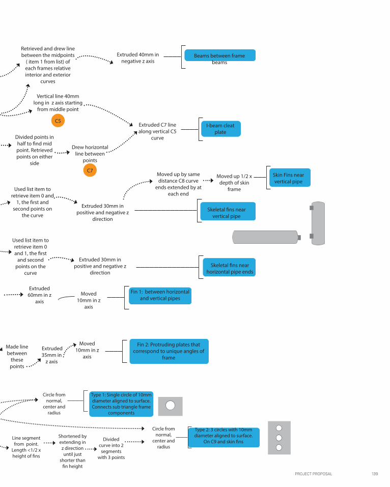
PROJECT PROPOSAL 139
Fin 2: Protruding plates that correspond to unique angles of
frame
Made line between
these points
Extruded 35mm in
z axis
Moved 10mm in z
axis
Divided points in half to find mid point. Retrieved points on either
side
Drew horizontal line between
points
Extruded C7 line along vertical C5
curve
Divided into 2 segments
Retrieved and drew line between the midpoints
( item 1 from list) of each frames relative interior and exterior
curves
Extruded 40mm in negative z axis
Vertical line 40mm long in z axis starting
from middle point
Beams between frame beams
I-beam cleat plate
Fin 1: between horizontal and vertical pipes
Divided into 2
Created line between
item 0 and 1
Extruded 60mm in z
axisMoved
10mm in z axis
C7
C5
Used list item to retrieve item 0 and
1, the first and second points on
the curve
Extruded 30mm in positive and negative z
direction
Used list item to retrieve item 0 and 1, the first
and second points on the
curve
Extruded 30mm in positive and negative z
direction
Skeletal fins near vertical pipe
Skeletal fins near horizontal pipe ends
Moved up by same distance C8 curve
ends extended by at each end
Moved up 1/2 x depth of skin
frame
Skin Fins near vertical pipe
Type 1: Single circle of 10mm diameter aligned to surface. Connects sub triangle frame
components
Shortened by extending in
z direction until just
shorter than fin height
Divided curve into 2
segments with 3 points
Type 2: 3 circles with 10mm diameter aligned to surface.
On C9 and skin fins Line segment from point.
Length <1/2 x height of fins
Circle from normal,
center and radius
Circle from normal,
center and radius

140 PROJECT PROPOSAL
FABRICATION
Cut triangular and trapezoid glazing panels according to digital model
specifications
1) Steel vertical pipe columns. Standard size throughout
design.
2) Custom fins and skeletal beams between poles with
specific angles.
3) Custom length poles and skin frame beams, I-beams and components. Can be modified
onsite if necessary.
TRIANGULAR FRAMING SYSTEM:
Bottom t-shaped plate of frame components screwed to main
frame beam.
Smaller triangulated units entirely assembled, with
subdivided framing components and beams joined
to main skin beams that run parallel to skeletal pipes
OFFSITE ASSEMBLY
JOINERY SYSTEM: fins welded to pipes.
Produce:
1
2Refined
Construction Process
TRANSPORT
Large pre- assembled
components
Smaller components: smaller triangular glazing units, joint
unit, individual panels, stones for triangular
platforms
Boat or large flat-bed truck
Smaller trucks or vans
Larger unassembled components: larger pipe & frame beams, glass panels
3
FIG 160. REFINED CONSTRUCTION PROCESS THAT INTEGRATES THE
NEW FULLY DEVELOPED TECTONIC SYSTEM WITH THE VERTICAL PIPE,
BEAM AND FIN CONNECTIONS.

PROJECT PROPOSAL 141
Ground bulk excavated & stage and seating area dug out
Extensive reinforced support system located under where amphitheatre structure will connect to the
ground to counterbalance the overhanging opening
Concrete ground laid
ONSITE4
AMPHITHEATRE
Skeleton beams bolted to horizontal skeletal pipe fins
Concrete -to-steel pipe components that connect skeletal support system to ground
and reinforcement installed
Bolted to fins of custom vertical joint pipe
Skeletal system erected
Larger framing units assembled onsite, directly to vertical pipe joints connected to
skeletal system
Preassembled smaller framing units lifted into position by cranes and fastened to main
skin beams via I-beams
Glazing installed in framing unit
Top plate of framing unit screwed down to secure glazing panel
LANDSCAPING:
Support for timber topped platforms
placed before timber planks laid
Grass filled platforms filled with dirt. Grass plantings installed
Triangular platform stone base laid
MAINTENANCE
Glazing system can be partially disassembled by removing the top layer of the frame. Allows for removal and replacement of damaged glazing units and
cleaning.
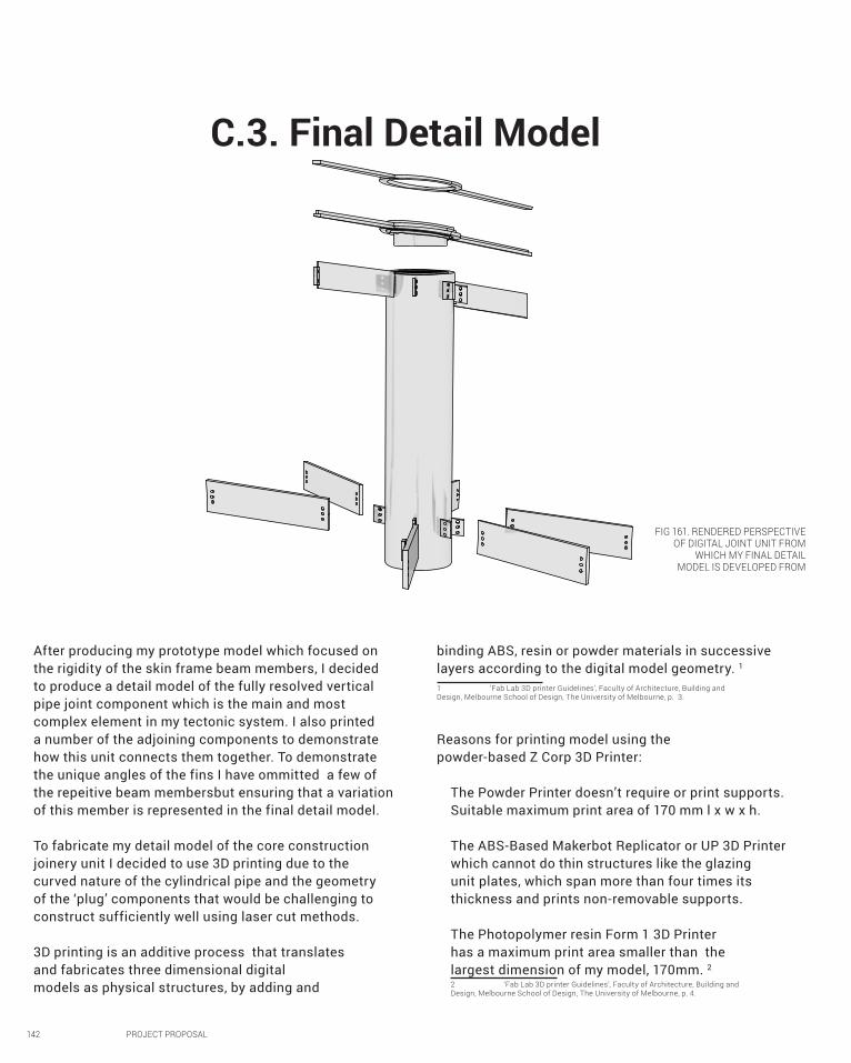
142 PROJECT PROPOSAL
C.3. Final Detail Model
After producing my prototype model which focused on the rigidity of the skin frame beam members, I decided to produce a detail model of the fully resolved vertical pipe joint component which is the main and most complex element in my tectonic system. I also printed a number of the adjoining components to demonstrate how this unit connects them together. To demonstrate the unique angles of the fins I have ommitted a few of the repeitive beam membersbut ensuring that a variation of this member is represented in the final detail model.
To fabricate my detail model of the core construction joinery unit I decided to use 3D printing due to the curved nature of the cylindrical pipe and the geometry of the ‘plug’ components that would be challenging to construct sufficiently well using laser cut methods.
3D printing is an additive process that translates and fabricates three dimensional digital models as physical structures, by adding and
binding ABS, resin or powder materials in successive layers according to the digital model geometry. 1
1 ‘Fab Lab 3D printer Guidelines’, Faculty of Architecture, Building and Design, Melbourne School of Design, The University of Melbourne, p. 3.
The Powder Printer doesn’t require or print supports. Suitable maximum print area of 170 mm l x w x h.
The ABS-Based Makerbot Replicator or UP 3D Printer which cannot do thin structures like the glazing unit plates, which span more than four times its thickness and prints non-removable supports.
The Photopolymer resin Form 1 3D Printer has a maximum print area smaller than the largest dimension of my model, 170mm. 2 2 ‘Fab Lab 3D printer Guidelines’, Faculty of Architecture, Building and Design, Melbourne School of Design, The University of Melbourne, p. 4.
Reasons for printing model using the powder-based Z Corp 3D Printer:
FIG 161. RENDERED PERSPECTIVE OF DIGITAL JOINT UNIT FROM
WHICH MY FINAL DETAIL MODEL IS DEVELOPED FROM

PROJECT PROPOSAL 143
ABS, resin or powder materials in successive layers according to the digital model geometry. 1
1 ‘Fab Lab 3D printer Guidelines’, Faculty of Architecture, Building and Design, Melbourne School of Design, The University of Melbourne, p. 3.
FIG 162. PHOTOGRAPH OF COMPLETE FINAL DETAIL MODEL WITH PROTRUDING BEAM ELEMENTS ATTACHED WITH ‘BOLTS’ AND GLAZING FRAME UNIT IN PLACE

FABRICATION PROCESS OF FINAL DETAIL MODEL
144 PROJECT PROPOSAL
A) Checked for Naked Edges to be joined.
Didn’t find any.
B) Converted solid polysurface geometry
into mesh, changing curved surfaces into
developable flat and triangulated surfaces.
C) Export mesh geometry as STL file to be
sent to FabLab for digital printing using the
3D Powder printer.
Adapted design for
fabrication purposes:
Protruding fins broke off during printing due to
thickness of fin and distance from screw holes to
edge of fin being less than recommended 2mm.
Although the actual fin elements used in construction
would be made of steel which is much stronger, this
complication has revealed possible points of structural
failure due to fragility which could prove to effect their
structural integrity and efficiency when constructed
Adjusted thickness of digital model, increasing fins
to 3mm thick and reducing the thickness of the pipe
for material efficiency. Maintained interior diameter
to ensure that glazing system plug would still fit.
Reprinted component 1:
FIG 164. COMPONENT 1B: REPRINTED VERTICAL PIPE WITH LARGER FINSFIG 163. COMPONENT 1A: VERTICAL PIPE WITH BROKEN FINS
1
2
FIG 162. RENDERED PERSPECTIVE OF DIGITAL
MESH GEOMETRY OF JOINT UNIT WHICH IS CONVERTED TO STL AND THEN SENT TO
FABLAB FOR PRINTING

FIG 165. COMPONENT 1A: SILVER COATED BEADS ACTING AS BOLT NUT
FIG 166. COMPONENT 1B ROUND TOPPED SILVER PINS CUT DOWN TO
REPRESENT BOLT HEAD AND SHAFT
FIG 167. COMPONENT 1: COMPONENTS 1A AND 1B JOIN TO FORM THE BOLT UNIT.
FIG 168. COMPONENT 2: BEAMS WITH CUSTOMIZED BOLT-END EDGES CORRESPONDING TO ANGLE OF CONNECTING STRUCTURAL MEMBERS
PROJECT PROPOSAL 145
Assembled component 1 and used it to fasten component 2 beams to corresponding protruding
fins on component 1A through aligned holes in fins and beams.
FIG 169-171. COMPONENT 4: GLAZING FRAME UNIT WITH PLUG:
A) T-SHAPED BOTTOM PLATE WITH ATTACHED ‘PLUG’; WITH
CORRESPONDINGB) TOP PLATE
3
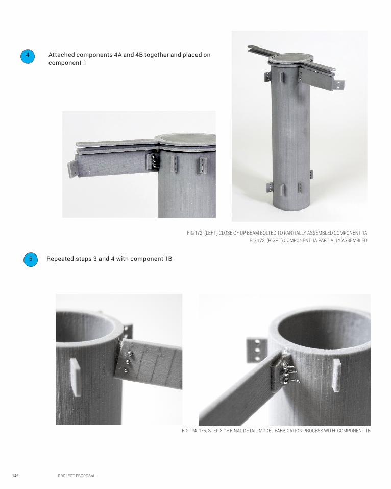
FIG 174 -175. STEP 3 OF FINAL DETAIL MODEL FABRICATION PROCESS WITH COMPONENT 1B
146 PROJECT PROPOSAL
FIG 172. (LEFT) CLOSE OF UP BEAM BOLTED TO PARTIALLY ASSEMBLED COMPONENT 1AFIG 173. (RIGHT) COMPONENT 1A PARTIALLY ASSEMBLED
Repeated steps 3 and 4 with component 1B5
Attached components 4A and 4B together and placed on
component 1
4

PROJECT PROPOSAL 147
FIG 176. (TOP LEFT) COMPONENT 1B WITHOUT BEAMS ATTACHED WITH GLAZING FRAME UNIT ONTOP
FIG 177. (MIDDLE LEFT) CLOSE UP OF GLAZING FRAME UNIT END RESTING ON SKIN FRAME BEAM
FIG 178. (RIGHT) CLOSE UP OF GAP BETWEEN TOP AND BOTTOM COMPONENTS OF GLAZING FRAME UNIT WHERE GLASS PANEL WOULD FIT
FIG 179. CLOSE UP OF SKIN SECTION OF FINAL DETAIL MODEL COMPLETELY ASSEMBLED

148 PROJECT PROPOSAL
FIG 180. CLOSE UP OF SKELETON PORTION OF JOINT UNIT COMPLETELY ASSEMBLED.
FIG 181. SYSTEM OF BOLTING BEAMS TO CORRESPONDING SKELETAL BEAMS

PROJECT PROPOSAL 149
FIG 182. PERSPECTIVE OF COMPLETED FINAL DETAIL MODEL OF JOINT UNIT

150 PROJECT PROPOSAL
C.4. Learning Objectives & Outcomes
OBJECTIVE 1: “INTERROGAT[ING] A BRIEF” BY CONSIDERING THE PROCESS OF BRIEF FORMATION IN THE AGE OF OPTIONEERING ENABLED BY DIGITAL TECHNOLOGIES;
optioneering offers the rapid and systematic exploration of numerous design options by utilizing parametric design tools. These outcomes, coupled with simulation analysis, are ‘sifted through’ by using Computational optimization to find the design that best fits the objectives of the brief. 1
Although I did not know it at the time, in part B I had begun exploring the rapid design methodology of optioneering in my production of over 80 design options in the generation of matrices intended to push the algorithms for BanQ and my own reverse engineered algorithm for the Swiss Re to their limits (Fig. 48-53, 70). Although I was mildly aware 1 David Gerber and Forest Flager, ‘Teaching Design Optioneering: A Method for Multidisciplinary Design Optimization’, Standford University Center for Integrated Facility Engineering, (2011), abstract, <http://cife.stanford.edu/node/713> [accessed 31 October 2014].
Objectives
Feedback from final presentation crit
Following my presentation, I received four main points of feedback during my crit, predominantly about improvements I could make in my graphic representation.
The first was that my tectonic system was well developed and utilized parametric modelling, a marked an improvement from the rudimentary spherical system I had developed in Part B.
Secondly, the exploded axonometric of the layers of the amphitheatre structure (Fig. 183) was unclear and could be improved. Following this advice, I did another exploded isometric plan that portrayed the designs layers more clearly (Fig. 146) by separating them further and ensuring that they didn’t overlap. Furthermore, as my design is relatively large and some of the elements in the layers quite small, I added close up views of the layers to provide greater clarity.
The third piece of feedback I received was that I needed to produce a rendering showing the experience from inside the structure. For the presentation I had used figure 185 to portray the atmosphere in the amphitheatre formed by the light shining through the patterned glass panels in their respective colours. As this render was not very good at achieving this objective I spent numerous hours producing more renders, exploring the materials and lighting settings. However, I was unable to render the underside of the glass panels which always came out grey or black, despite following instructions and tutorials online on rendering materiality with V-ray. Instead, I took to Photoshop to create this atmosphere, selecting and colouring the panels ‘manually’ with their respective hues and levels of transparency,
which created the glowing blue effect I had envisaged.
Lastly, the renders I had included in the presentation didn’t sufficiently demonstrate the use of colour in the panels, and consequently didn’t do the design justice. To remedy this I reviewed the renders, and found that in some of them the representation of the colouring greatly improved just by lightening the weight of the vector line-work which had drowned out and overpowered the rendered image. I also produced a number of other perspective renders like figure 129 in which the colouring ‘pops’.

PROJECT PROPOSAL 151
Objectives
that these iterations formed part of the explorative process leading up to the final design for the LAGI brief, the objectives of the brief had not largely influenced the manner in which I produced them. I moved away from the energy objective of the LAGI brief and instead developed my own selection criteria to select the most successful design outcome through my own logic and reasoning rather than through simulation analysis or computational optimization. In this regard I had not utilized the second component of optioneering in the development of my final design. However, I had begun exploring the use of such analysis in my week 7 sketch (fig. 49-52 of sketchbook). Provided with more time I would have liked to utilize this analytical algorithm to explore my design further by tilting the glass panels with the objective of receiving solar radiation and utilizing this analystical algorithm to determine their angle according to which angle would allow for maximum solar penetration.
OBJECTIVE 2: DEVELOPING “AN ABILITY TO GENERATE A VARIETY OF DESIGN POSSIBILITIES FOR A GIVEN SITUATION” BY INTRODUCING VISUAL PROGRAMMING, ALGORITHMIC DESIGN AND PARAMETRIC MODELLING WITH THEIR INTRINSIC CAPACITIES FOR EXTENSIVE DESIGN-SPACE EXPLORATIONJust as I had done with my exploration of the reverse engineered algorithm for the Swiss Re (Fig. 70), My final design was achieved through the development of various algorithms and exploration of iterations generated from them until I reached a design option that I deemed to be the most successful. This was especially the case for determining the most successful patterning and landscaping arrangements.
OBJECTIVE 3: DEVELOPING “SKILLS IN VARIOUS THREE- DIMENSIONAL MEDIA” AND SPECIFICALLY IN COMPUTATIONAL GEOMETRY, PARAMETRIC MODELLING, ANALYTIC DIAGRAMMING AND DIGITAL FABRICATION;
Quite frankly I’m surprised at how much my parametric modelling techniques have improved since the start of the semester when I had no previous experience or even knowledge of computation, parametrics or programming and only minimal experience. From my initial difficulty and hesitation to generate a volume algorithmically in the week 1 sketch task (Fig. 2 sketchbook), I have since formed the monster of a definition that encompasses numerous smaller algorithms to produce my whole design (Fig. 81 sketchbook). Although my skills could still improve, they have excelled what I expected to be able to achieve in this short time. While I saw some appreciation for the efficiency for using algorithms to design repetitive elements, I had not fully understood the advantages of using this capability until I developed the joinery unit of my tectonic system in C.2. The idea of manually producing each fin plate at specific angles that correspond to the angle that their adjoining beam or pipe members need to be orientated in order to form the shape of the amphitheatre, is quite frankly terrifying!
OBJECTIVE 4: DEVELOPING “AN UNDERSTANDING OF RELATIONSHIPS BETWEEN ARCHITECTURE AND AIR” THROUGH INTERROGATION OF DESIGN PROPOSAL AS PHYSICAL MODELS IN ATMOSPHERE;
Considering the design within the context of the surroundings is an important element in design development as the scale, orientation and aesthetic relationship with surrounding buildings cannot be fully understood until they are considered in tandem

152 PROJECT PROPOSAL
design, and utilizing Photoshop to portray the emotive atmosphere experienced within the amphitheatre due to the patterning of the glass in different hues of blue.
OBJECTIVE 6: DEVELOP CAPABILITIES FOR CONCEPTUAL, TECHNICAL AND DESIGN ANALYSES OF CONTEMPORARY ARCHITECTURAL PROJECTS;
Although the majority of My exploration of contemporary architectural projects was mainly done in parts A and B, the knowledge I gained from their analysis carried through to part C, especially the skeleton and skin system employed in the design of the Swiss Re which remained a prominent aspect of my final design and drove its development. While I did not use specific precedents in developing my tectonic system, I took inspiration from traditional construction methodologies and the standard tectonic system associated with curtain wall systems.
OBJECTIVE 7: DEVELOP FOUNDATIONAL UNDERSTANDINGS OF COMPUTATIONAL GEOMETRY, DATA STRUCTURES AND TYPES OF PROGRAMMING;
Getting a handle on programming logic or ‘algorithmic thinking’ was probably the hardest part of the design process for me. While I could follow video tutorials and instructions relatively easily, I struggled to apply them to other scenarios. Although I felt I had understood the theory in the particular instance used in the tutorial, ran into road-blocks. As I waged through this difficult learning process, I began to become more confident in adapting algorithms and began programming my own algorithms from scratch. This shift is evident in my second attempt at the array of seats along a set of stairs. The initial attempt, employed and developed in part B, drew inspiration from an amalgamation of tutorials and instructions and resulted in fiddly
with the site. I was very aware of the large scale of the design site from the onset. This awareness largely drove the development of my design, influencing my decision to propose designing according to the programme of a concert hall/amphitheatre that takes advantage not only of the large site but also of its relative isolation from areas that would be bothered by loud sounds. I also began exploring how the rest of the site would be used in relation to the main amphitheatre feature. Transforming the digital design of my tectonic system into two physical models, a prototype to test the overall system and a final detail of the main element of this system, the vertical pipe joint, allowed me test whether they would be structurally feasible.
OBJECTIVE 5: DEVELOPING “THE ABILITY TO MAKE A CASE FOR PROPOSALS” BY DEVELOPING CRITICAL THINKING AND ENCOURAGING CONSTRUCTION OF RIGOROUS AND PERSUASIVE ARGUMENTS INFORMED BY THE CONTEMPORARY ARCHITECTURAL DISCOURSE.
Case proposals can be a bit of a mixed experience for me. Although I may not have graphically represented my presentations as well as some other individuals did, I happily took the criticism and attempted to address the suggestions made to improve the conveyance of my ideas graphically. This transformation in my graphic representation is evident in the evolution of my renders. My interim presentation and part B renders were very rudimentary renders using rhino, while I started to explore the capabilities of V-ray for my final presentation and part C. Utilizing V-ray allowed me to show the materiality of my design more effectively, with the transparency of the glass and shine of the steel members portraying the lightness of the structure I had envisaged. Following my final presentation I improved my representation further, adjusting the thicknesses of the vector lines, re-doing my exploded axonometric to more clearly portray my

PROJECT PROPOSAL 153
outcome that didn’t line up and a set number of stairs that I struggled to adjust. The second attempt I developed using the general knowledge I had gained of programming logic, manipulating the lists and trees with cull lists and putting them into series for further manipulation, worked a charm. The arrangement of the seats matched the curvature of the steps and I could easily change the tread and riser of the stairs and the steps would follow!
OBJECTIVE 8: BEGIN DEVELOPING A PERSONALISED REPERTOIRE OF COMPUTATIONAL TECHNIQUES SUBSTANTIATED BY THE UNDERSTANDING OF THEIR ADVANTAGES, DISADVANTAGES AND AREAS OF APPLICATION.
I never thought it would be possible but I have come to feel as though I have developed (somewhat) of a Handle of culling lists, at least relative to my initial battle against them in the week 3 sketch. In generating my final design I employed culling in almost every algorithm I developed. One technique that I became particularly versed in is using cull lists to selected items based on their distance from a set point and manipulating them according to this distance. I used this technique in the triangular platform landscaping, to exclude the triangles immediately surrounding and underneath the amphitheatre, to increase their size as they near the amphitheatre and to increase in elevation according to their distance to referenced curve.
In developing my tectonic system I came to appreciate the advantages and also encountered the disadvantages of algorithmic modelling. While it allowed me to repeat my joinery system throughout the design, some of the elements that formed the smaller triangular units were too close and overlapped. The complex geometry I was able
to achieve by utilizing grasshopper hindered my ability to apply my tectonic system throughout its entirety without encountering some hiccups. To develop these few overlaps I would need to address them individually.
Though this has been a hard uphill battle to get a handle on algorithmic and parametric modelling and programming, riddled with bouts of frustrated road blocks, I have come out of it happy with the progress I have made. Never had I thought I would be able to design such a geometrically complex and intricate design through a method in which I didn’t have a designed structure already in mind. Although I was hesitant to embrace them, and am still relatively new to it, I can see the benefits of computational and generative techniques and plan to utilize them, where suitable, in my future designs.

154 PROJECT PROPOSAL
Appendix of renders produced for final presentation that I have since improved
FIG 183. EXPLODED ISOMETRIC PLAN PRODUCED FOR FINAL PRESENTATION WHICH HAS
SINCE BEEN REVISED AS FIGURE 146 WHICH MORE CLEARLY
PORTRAYS THE DESIGN

PROJECT PROPOSAL 155
FIG 184. RENDERED PERSPECTIVE USED IN FINAL PRESENTATION. I DID FURTHER RENDERS (FIG. 127-130) WITH IMPROVED MATERIALITY, LIGHTING AND LINE WEIGHTS THAT MORE EFFECTIVELY CONVEY MY DESIGN.
FIG 185. RENDERED PERSPECTIVE USED IN FINAL PRESENTATION TO PORTRAY THE ATMOSPHERE IN THE AMPHITHEATRE FORMED BY THE LIGHT SHINING THROUGH THE PATTERNED GLASS.

156 PROJECT PROPOSAL
Part C Image List
Part C Bibliography
Fig 110-118. Waring, Sarah, Rhino renders using Grasshopper, Studio Air, (2014).
Fig 119. ‘Aerial photo of site’, LAGI 2014 Annex Documents, LAGI, <http://landartgenerator.org/designcomp/> [accessed 1 October 2014].
Fig 120. ‘Panoramic view from site, LAGI 2014 Annex Documents, LAGI, <http://landartgenerator.org/designcomp/>[accessed 1 October 2014].
Fig 121. ‘ Panoramic view of waterfront from site’,LAGI 2014 Annex Documents, LAGI, http://landartgenerator.org/designcomp/.
Fig 122. ‘Aerial photo of site’, LAGI 2014 Annex Documents, LAGI, <http://landartgenerator.org/designcomp/> [accessed 1 October 2014].
Fig 123. Waring, Sarah, Rhino renders using Grasshopper, Studio Air, (2014).
Fig 124. ‘Aerial perspective photo of site’, LAGI 2014 Annex Documents, LAGI, < http://
landartgenerator.org/designcomp/> [accessed 1 October 2014].
Fig 125-140. Waring, Sarah, Rhino renders using Grasshopper, Studio Air, (2014).
Fig 141. ‘Simple connections’, SteelConstruction.info, <http://www.steelconstruction.info/Simple_
connections#Beam-to-beam_and_beam-to-column_connections >[accessed 10 October 2014].
Fig 143. Leia Mais, ‘Spider Glass’, Alumigraph, <http://www.alumigraph.com.br/galeria.html> [accessed 11 October 2014].
Fig 144. PittCo ‘Aluminum and glass curtain wall’, ArchiExpo, <http://www.archiexpo.com/
prod/pittco-architectural-metals-inc/aluminum-glass-curtain-walls-58265-493490.html
> [accessed 12 October 2014].
‘Fab Lab 3D printer Guidelines’, Faculty of Architecture, Building and Design, Melbourne School of Design, The University of Melbourne.
Ferry, Robert and Elizabeth Monoian, ‘LAGI 2014 Design Guidelines’, http://landartgenerator.org/designcomp/ [accessed 10 October 2014].
Gerber, D. and Forest Flager, ‘Teaching Design Optioneering: A Method for Multidisciplinary Design Optimization’, Standford University
Center for Integrated Facility Engineering, (2011), abstract, <http://cife.stanford.edu/node/713> [accessed 31 October 2014].
‘Simple connections’, SteelConstruction.info, http://www.steelconstruction.info/Simple_connections#Beam-
to-beam_and_beam-to-column_connections [accessed 10 October 2014].
Vigener, Nik, PE. and Mark A. Brown, ‘Building Envelope Design Guide – Curtain Walls’, Whole Building Design Guide,
(2012), <http://www.wbdg.org/design/env_fenestration_cw.php> [accessed 13 October 2014] .

PROJECT PROPOSAL 157
FIG 186: THE END PRODUCT OF A SEMETERS WORHT OF EXPLORATION OF ALGORITHMIC MODELLING AND PARAMETRIC DESIGN