

3G UMTS / WCDMA technologiesThere are several key areas of 3G UMTS / WCDMA. Within these there are several key
technologies that have been employed to enable UMTS / WCDMA to provide a leap in performance
over its 2G predecessors.
Some of these key areas include:
Radio interface: The UMTS radio interface provides the basic definition of the radio signal.
W-CDMA occupies 5 MHz channels and has defined formats for elements such as
synchronisation, power control and the like Read more about the UMTS / W-CDMA radio
interface.
CDMA technology : 3G UMTS relies on a scheme known as CDMA or code divison
multiple access to enable multiple handsets or user equipments to have access to the base
station. Using a scheme known as direct sequence spread spectrum, different UEs have
different codes and can all talk to the base station even though they are all on the same
frequency Read more about the code division multiple access.
UMTS network architecture: The architecture for a UMTS network was designed to
enable packet data to be carried over the network, whilst still enabling it to support circuit
switched voice. All the usual functions enabling access toth e network, roaming and the like
are also supported. Read more about the UMTS network architecture.
UMTS modulation schemes: Within the CDMA signal format, a variety of forms of
modulation are used. These are typically forms of phase shift keying. Read more about
the modulation schemes.
UMTS channels: As with any cellular system, different data channels are required for
passing payload data as well as control information and for enabling the required resources
to be allocated. A variety of different data channels are used to enable these facilities to be
accomplishedRead more about the physical & logical channels.
UMTS TDD: There are two methods of providing duplex for 3G UMTS. One is what is
termed frequency division duplex, FDD. This uses two channels spaced sufficiently apart so
that the receiver can receive whilst the transmitter is also operating. Another method is to
use time vision duplex, TDD where short time blocks are allocated to transmissions in both
directions. Using this method, only a single channel is required Read more about the TDD
system.
Handover: One key area of any cellular telecommunications system is the handover
(handoff) from one cell to the next. Using CDMA there are several forms of handover that are
implemented within the system. Read more about the Handover.
3G UMTS enhancements

The basic 3G UMTS cellular system enabled data rates up to 2048kbps to be achieved. However as
the use of data rapidly increased, these figures were no longer sufficient and further data rate
increases were required.
A scheme known as HSDPA, high speed packet download access was first introduced to enable the
downlink speed to be increased. This was followed with HSUPA, high speed packet uplink access
was introduced. The combined suite was then known as HSPA, high speed packet access.
Note on HSPA, High Speed Packet Access:
High speed packet access added additional channels and signalling to the downlink (HSDPA) and in the Uplink
(HSUPA). By adding these channels, significant increases in data rates and capacity have been achieved.
Click on the link for further information about High Speed Packet Access, HSPA
UMTS WCDMA specification summaryThe UMTS WCDMA system offered a significant improvement in capability over the previous 2G
services.
3G UMTS SPECIFICATION SUMMARY
PARAMETER SPECIFICATION
Maximum data rate 2048 kbps low range384 kbps urban and outdoor
RF channel bandwidth 5 MHz
Multiple access scheme CDMA
Duplex schemes FDD and also TDD
The basic 3G UMTS is able to provide a reasonable data transfer rate, although by the latest
standards it is relatively slow. Nevertheless 3G UMTS paved the way for mobile broadband,
providing data rates that were unequalled at the time.
The UMTS 3G architecture is required to provide a greater level of performance to that of the original
GSM network. However as many networks had migrated through the use of GPRS and EDGE, they
already had the ability to carry data. Accordingly many of the elements required for the WCDMA /

UMTS network architecture were seen as a migration. This considerably reduced the cost of
implementing the UMTS network as many elements were in place or needed upgrading.
With one of the major aims of UMTS being to be able to carry data, the UMTS network architecture
was designed to enable a considerable improvement in data performance over that provided for
GSM.
3G UMTS network constituentsThe UMTS network architecture can be divided into three main elements:
1. User Equipment (UE): The User Equipment or UE is the name given to what was previous
termed the mobile, or cellphone. The new name was chosen because the considerably
greater functionality that the UE could have. It could also be anything between a mobile
phone used for talking to a data terminal attached to a computer with no voice capability.
2. Radio Network Subsystem (RNS): The RNS also known as the UMTS Radio Access
Network, UTRAN, is the equivalent of the previous Base Station Subsystem or BSS in GSM.
It provides and manages the air interface fort he overall network.
3. Core Network: The core network provides all the central processing and management for
the system. It is the equivalent of the GSM Network Switching Subsystem or NSS.
The core network is then the overall entity that interfaces to external networks including the public
phone network and other cellular telecommunications networks.
UMTS Network Architecture Overview

User Equipment, UEThe USER Equipment or UE is a major element of the overall 3G UMTS network architecture. It
forms the final interface with the user. In view of the far greater number of applications and facilities
that it can perform, the decision was made to call it a user equipment rather than a mobile. However
it is essentially the handset (in the broadest terminology), although having access to much higher
speed data communications, it can be much more versatile, containing many more applications. It
consists of a variety of different elements including RF circuitry, processing, antenna, battery, etc.
There are a number of elements within the UE that can be described separately:
UE RF circuitry: The RF areas handle all elements of the signal, both for the receiver and
for the transmitter. One of the major challenges for the RF power amplifier was to reduce the
power consumption. The form of modulation used for W-CDMA requires the use of a linear
amplifier. These inherently take more current than non linear amplifiers which can be used
for the form of modulation used on GSM. Accordingly to maintain battery life, measures were
introduced into many of the designs to ensure the optimum efficiency.
Baseband processing: The base-band signal processing consists mainly of digital
circuitry. This is considerably more complicated than that used in phones for previous
generations. Again this has been optimised to reduce the current consumption as far as
possible.
Battery: While current consumption has been minimised as far as possible within the
circuitry of the phone, there has been an increase in current drain on the battery. With users
expecting the same lifetime between charging batteries as experienced on the previous
generation phones, this has necessitated the use of new and improved battery technology.
Now Lithium Ion (Li-ion) batteries are used. These phones to remain small and relatively light
while still retaining or even improving the overall life between charges.
Universal Subscriber Identity Module, USIM: The UE also contains a SIM card, although
in the case of UMTS it is termed a USIM (Universal Subscriber Identity Module). This is a
more advanced version of the SIM card used in GSM and other systems, but embodies the
same types of information. It contains the International Mobile Subscriber Identity number
(IMSI) as well as the Mobile Station International ISDN Number (MSISDN). Other information
that the USIM holds includes the preferred language to enable the correct language
information to be displayed, especially when roaming, and a list of preferred and prohibited
Public Land Mobile Networks (PLMN).
The USIM also contains a short message storage area that allows messages to stay with the
user even when the phone is changed. Similarly "phone book" numbers and call information
of the numbers of incoming and outgoing calls are stored.

The UE can take a variety of forms, although the most common format is still a version of a "mobile
phone" although having many data capabilities. Other broadband dongles are also being widely
used.
3G UMTS Radio Network SubsystemThis is the section of the 3G UMTS / WCDMA network that interfaces to both the UE and the core
network. The overall radio access network, i.e. collectively all the Radio Network Subsystem is
known as the UTRAN UMTS Radio Access Network.
The radio network subsystem is also known as the UMTS Radio Access Network or UTRAN.
Read more about the UMTS Radio Access Network.
3G UMTS Core NetworkThe 3G UMTS core network architecture is a migration of that used for GSM with further elements
overlaid to enable the additional functionality demanded by UMTS.
In view of the different ways in which data may be carried, the UMTS core network may be split into
two different areas:
Circuit switched elements: These elements are primarily based on the GSM network
entities and carry data in a circuit switched manner, i.e. a permanent channel for the duration
of the call.
Packet switched elements: These network entities are designed to carry packet data. This
enables much higher network usage as the capacity can be shared and data is carried as
packets which are routed according to their destination.
Some network elements, particularly those that are associated with registration are shared by both
domains and operate in the same way that they did with GSM.
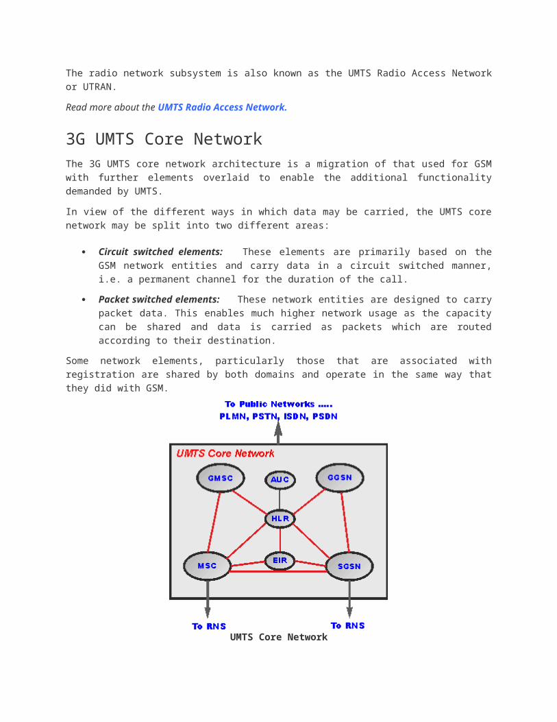
UMTS Core Network
Circuit switched elements
The circuit switched elements of the UMTS core network architecture include the following network
entities:
Mobile switching centre (MSC): This is essentially the same as that within GSM, and it
manages the circuit switched calls under way.
Gateway MSC (GMSC): This is effectively the interface to the external networks.
Packet switched elements
The packet switched elements of the 3G UMTS core network architecture include the following
network entities:
Serving GPRS Support Node (SGSN): As the name implies, this entity was first
developed when GPRS was introduced, and its use has been carried over into the UMTS
network architecture. The SGSN provides a number of functions within the UMTS network
architecture.
o Mobility management When a UE attaches to the Packet Switched domain of the
UMTS Core Network, the SGSN generates MM information based on the mobile's
current location.
o Session management: The SGSN manages the data sessions providing the
required quality of service and also managing what are termed the PDP (Packet data
Protocol) contexts, i.e. the pipes over which the data is sent.

o Interaction with other areas of the network: The SGSN is able to manage its
elements within the network only by communicating with other areas of the network,
e.g. MSC and other circuit switched areas.
o Billing: The SGSN is also responsible billing. It achieves this by monitoring the flow
of user data across the GPRS network. CDRs (Call Detail Records) are generated by
the SGSN before being transferred to the charging entities (Charging Gateway
Function, CGF).
Gateway GPRS Support Node (GGSN): Like the SGSN, this entity was also first
introduced into the GPRS network. The Gateway GPRS Support Node (GGSN) is the central
element within the UMTS packet switched network. It handles inter-working between the
UMTS packet switched network and external packet switched networks, and can be
considered as a very sophisticated router. In operation, when the GGSN receives data
addressed to a specific user, it checks if the user is active and then forwards the data to the
SGSN serving the particular UE.
Shared elements
The shared elements of the 3G UMTS core network architecture include the following network
entities:
Home location register (HLR): This database contains all the administrative information
about each subscriber along with their last known location. In this way, the UMTS network is
able to route calls to the relevant RNC / Node B. When a user switches on their UE, it
registers with the network and from this it is possible to determine which Node B it
communicates with so that incoming calls can be routed appropriately. Even when the UE is
not active (but switched on) it re-registers periodically to ensure that the network (HLR) is
aware of its latest position with their current or last known location on the network.
Equipment identity register (EIR): The EIR is the entity that decides whether a given UE
equipment may be allowed onto the network. Each UE equipment has a number known as
the International Mobile Equipment Identity. This number, as mentioned above, is installed in
the equipment and is checked by the network during registration.
Authentication centre (AuC) : The AuC is a protected database that contains the secret
key also contained in the user's USIM card.
Physical layer within UMTS / WCDMA is totally different to that employed by GSM. It employs a
spread spectrum transmission in the form of CDMA rather than the TDMA transmissions used for
GSM. Additionally it currently uses different frequencies to those allocated for GSM.
The UTRA, UMTS radio access is the technology that is the radio interface, and the network, or
UMTS Radio Access Network is known as the UTRAN. Sometimes the UTRAN may also be known
as the Radio Network Subsystem, or RNS.
UMTS radio access network, UTRAN

The UMTS Radio Access Network, UTRAN, or Radio Network Subsystem, RNS comprises two main
components:
Radio Network Controller, RNC: This element of the UTRAN / radio network subsystem
controls the Node Bs that are connected to it, i.e. the radio resources in its domain.. The
RNC undertakes the radio resource management and some of the mobility management
functions, although not all. It is also the point at which the data encryption / decryption is
performed to protect the user data from eavesdropping.
Node B: Node B is the term used within UMTS to denote the base station transceiver. This
part of the UTRAN contains the transmitter and receiver to communicate with the UEs within
the cell. It participates with the RNC in the resource management. NodeB is the 3GPP term
for base station, and often the terms are used interchangeably.
In order to facilitate effective handover between Node Bs under the control of different RNCs, the
RNC not only communicates with the Core Network, but also with neighbouring RNCs.
3G UMTS UTRAN Architecture
UTRAN interfacesThe UMTS standards are structured in a way that the internal functionality of the different network
elements is not defined. Instead, the interfaces between the network elements is defined and in this
way, so too is the element functionality.
There are several interfaces that are defined for the UTRAN elements:
Iub : The Iub connects the NodeB and the RNC within the UTRAN. Although when it was
launched, a standardisation of the interface between the controller and base station in the
UTRAN was revolutionary, the aim was to stimulate competition between suppliers, allowing
opportunities like some manufacturers who might concentrate just on base stations rather
than the controller and other network entities.

Iur : The Iur interface allows communication between different RNCs within the UTRAN.
The open Iur interface enables capabilities like soft handover to occur as well as helping to
stimulate competition between equipment manufacturers.
Iu : The Iu interface connects the UTRAN to the core network.
Having standardised interfaces within various areas of the network including the UTRAN allows
network operators to select different network entities from different suppliers.
UTRA uplink & downlinkWhen looking at the radio air interface and its associated properties, it is necessary to define the
directions in which the transmissions are occurring. Being a full duplex system, i.e. transmitting
simultaneously in both directions, it is necessary to be able to define which direction is which.
Uplink; This may also sometimes be known as the reverse link, and it is the link from the
User Equipment (UE) to the Node B or base station.
Downlink; This may also sometimes be known as the forward link, and it is the link from
the Node B or base station to the User Equipment (UE).
The terms Uplink and Downlink are the terms that are used with UMTS, and especially within
Europe. The terms forward link and reverse link are more commonly used with the CDMA2000
technologies and also within North America.
Uplink and downlink transmission directions
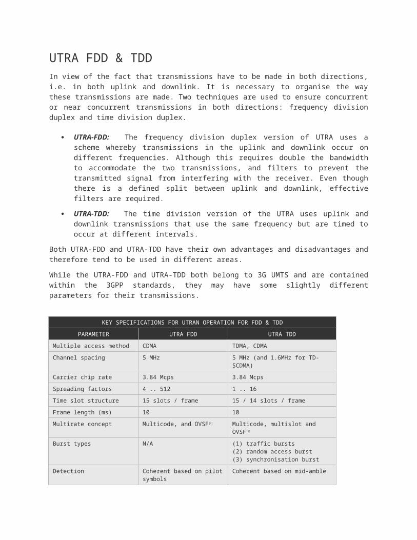
UTRA FDD & TDDIn view of the fact that transmissions have to be made in both directions, i.e. in both uplink and
downlink. It is necessary to organise the way these transmissions are made. Two techniques are
used to ensure concurrent or near concurrent transmissions in both directions: frequency division
duplex and time division duplex.
UTRA-FDD: The frequency division duplex version of UTRA uses a scheme whereby
transmissions in the uplink and downlink occur on different frequencies. Although this
requires double the bandwidth to accommodate the two transmissions, and filters to prevent

the transmitted signal from interfering with the receiver. Even though there is a defined split
between uplink and downlink, effective filters are required.
UTRA-TDD: The time division version of the UTRA uses uplink and downlink transmissions
that use the same frequency but are timed to occur at different intervals.
Both UTRA-FDD and UTRA-TDD have their own advantages and disadvantages and therefore tend
to be used in different areas.
While the UTRA-FDD and UTRA-TDD both belong to 3G UMTS and are contained within the 3GPP
standards, they may have some slightly different parameters for their transmissions.
KEY SPECIFICATIONS FOR UTRAN OPERATION FOR FDD & TDD
PARAMETER UTRA FDD UTRA TDD
Multiple access method CDMA TDMA, CDMA
Channel spacing 5 MHz 5 MHz (and 1.6MHz for TD-SCDMA)
Carrier chip rate 3.84 Mcps 3.84 Mcps
Spreading factors 4 .. 512 1 .. 16
Time slot structure 15 slots / frame 15 / 14 slots / frame
Frame length (ms) 10 10
Multirate concept Multicode, and OVSF[1] Multicode, multislot and OVSF[1]
Burst types N/A (1) traffic bursts(2) random access burst(3) synchronisation burst
Detection Coherent based on pilot symbols
Coherent based on mid-amble
Dedicated channel power control
Fast closed loop 1500 Hz rate Uplink: open loop 100 Hz or 200 Hz rateDownlink: closed loop max 800 Hz rate
Notes
[1] OVSF = Orthogonal Variable Spreading Factor
The Physical layer is one of the key elements that differentiates the various cellular systems that
operate. Although there is very much more to a cellular system than just the physical layer, it is one
of the aspects that gains a high level of visibility.
The UMTS physical layer is totally different to that employed by GSM. It employs a spread spectrum
transmission in the form of CDMA rather than the TDMA transmissions used for GSM. Additionally it
currently uses different frequencies to those allocated for GSM.
UMTS physical layer signal formatOne of the chief elements of the UMTS physical layer or radio interface is the signal format that has
been adopted.
The UMTS physical layer utilises direct sequence spread spectrum format to enable a multiple
access scheme called Code Division Multiple Access, CDMA to be used.
Using CDMA, multiple users share the same channel, but different users are allocated different
codes, and in this way the system is able to distinguish between the different users.
Read more about UMTS CDMA
The CDMA signal is 5MHz and in view of this, the UMTS physical layer is often referred to as
Wideband CDMA, W-CDMA. This compares to the US based cdmaOne and cdma2000 systems that
use a 1.25 MHz bandwidth.
UMTS transmitted signal characteristicsOne key element of the UMTS physical layer is the definition of the transmitted signal
characteristics. It is necessary to define the overall signal bandwidth and shape so that interference
is minimised for adjacent channels and users.The pulse shaping applied to the transmitted signals is
root raised cosine filtering with a roll-off-factor of 0.22.
The nominal carrier spacing is 5MHz, and the carrier centre frequencies are normally divisible by 5,
but the carrier frequency can be adjusted in increments of 200kHz. Accordingly the centre frequency
of UMTS carriers are indicated with an accuracy of 200kHz. This adjustment can be used to provide
operators with a more flexible use of their available spectrum.
One important characteristic of the signal is the way in which the signal spreads out either side of the
central area, and affecting other channels. It is never possible to have complete isolation or infinite
filtering and therefore spectral masks are defined showing elves that must be achieved for
compliance with the standard.
UMTS physical layer spectral mask
Shown in the diagram of the UMTS physical layer signal is the Adjacent Channel Leakage Ratio.
This is a measure of the signal level that appears in adjacent channels. ACLR 1 is the level in the
channel one up or down from the signal, and ACLR2 is two channels up or down.

The requirements are not surprisingly more stringent for base stations / NodeBs than for the
handsets or UEs.
ACLR REQUIREMENTS FOR UMTS PHYSICAL LAYER
ACLR1 ACLR2
UE / handset* 33dB 43dB
Base station 45dB 50dB
* ACLR values for handsets with power classes of 21dBm and 24dBm.
SynchronisationThe level of synchronisation required for the WCDMA system to operate is provided from the
Primary Synchronisation Channel (P-SCH) and the Secondary Synchronisation Channel (S-SCH).
These channels are treated in a different manner to the normal channels and as a result they are not
spread using the OVSFs and PN codes. Instead they are spread using synchronisation codes. There
are two types that are used. The first is called the primary code and is used on the P-SCH, and the
second is named a secondary code and is used on the S-SCH.
The primary code is the same for all cells and is a 256 chip sequence that is transmitted during the
first 256 chips of each time slot. This allows the UE to synchronise with the base station for the time
slot.
Once the UE has gained time slot synchronisation it only knows the start and stop of the time slot,
but it does not know information about the particular time slot, or the frame. This is gained using the
secondary synchronisation codes.
There is a total of sixteen different secondary synchronisation codes. One code is sent at the
beginning of the time slot, i.e. the first 256 chips. It consists of 15 synchronisation codes and there
are 64 different scrambling code groups. When received, the UE is able to determine before which
synchronisation code the overall frame begins. In this way the UE is able to gain complete
synchronisation.
The scrambling codes in the S-SCH also enable the UE to identify which scrambling code is being
used and hence it can identify the base station. The scrambling codes are divided into 64 code
groups, each having eight codes. This means that after achieving frame synchronisation, the UE
only has a choice of one in eight codes and it can therefore try to decode the CPICH channel. Once
it has achieved this it is able to read the BCH information and achieve better timing and it is able to
monitor the P-CCPCH.
UMTS power control

As with any CDMA system it is essential that the base station receives all the UEs at approximately
the same power level. If not, the UEs that are further away will be lower in strength than those closer
to the node B and they will not be heard. This effect is often referred to as the near-far effect. To
overcome this the node B instructs those stations closer in, to reduce their transmitted power, and
those further away to increase theirs. In this way all stations will be received at approximately the
same strength.
It is also important for node Bs to control their power levels effectively. As the signals transmitted by
the different node Bs are not orthogonal to one another it is possible that signals from different ones
will interfere. Accordingly their power is also kept to the minimum required by the UEs being served.
To achieve the power control there are two techniques that are employed: open loop; and closed
loop.
Open loop techniques are used during the initial access before communication between the UE and
node B has been fully established. It simply operates by making a measurement of the received
signal strength and thereby estimating the transmitter power required. As the transmit and receive
frequencies are different, the path losses in either direction will be different and therefore this
method cannot be any more than a good estimate.
Once the UE has accessed the system and is in communication with the node B, closed loop
techniques are used. A measurement of the signal strength is taken in each time slot. As a result of
this a power control bit is sent requesting the power to be stepped up or down. This process is
undertaken on both the up and downlinks. The fact that only one bit is assigned to power control
means that the power will be continually changing. Once it has reached approximately the right level
then it would step up and then down by one level. In practice the position of the mobile would
change, or the path would change as a result of other movements and this would cause the signal
level to move, so the continual change is not a problem.
There are very many frequency bands that are used to carry the 3G UMTS transmissions.
These frequency bands are allocated on an international basis to enable roaming and also to
allocate bands internationally to minimise interference.
UMTS frequency bands backgroundAs the use of 3G UMTS has grown, so too has the requirement for frequency allocations. Initially
bands in the region of 1885 - 2025 and 2110 - 2200 MHz were set aside.
These frequency bands were originally set aside at the World Administrative radio Conference in
1992, to enable use on a worldwide basis by administrations wishing to implement International
Mobile Telecommunications-2000, IMT-2000.
As the requirement for additional spectrum grew with the increased use of 3G UMTS, more
allocations were set aside.

Although not all bands are available in all countries, all bands are managed on an international
basis. In this way roaming is possible.
3G UMTS bandwidthUMTS uses wideband CDMA as the radio transport mechanism and the UMTS channels are spaced
by 5 MHz.
The UMTS signal bandwidth is normally considered to be 5 MHz but this figure includes the 0.58
MHz guard bands either side.
Therefore when the two guard bands, one either side, are excluded this leaves and effective signal
bandwidth of 3.84 MHz within the flat response area of the signal for the transmission itself.
It is also necessary to consider the roll-off factor for the signal of 0.22. This roll-off factor is
determined by the Root Raised Cosine filter specified by 3GPP. This means that the total signal
bandwidth increasing the skirts is 4.68 MHz.
It is also worth noting that the bandwidth used for the TD-SCDMA variant of 3G UMTS used in China
is 1.6 MHz.
UARFCN channel numbersUMTS carrier frequencies are designated by a UTRA Absolute Radio Frequency Channel Number,
UARFCN. The UARFCN is used to define channel numbers in an easy and unambiguous fashion.
The UARFCN can be easily calculated from the following equation or formula:
The UARFCN is only able to represent channels that are centred on a multiple of 200 kHz and these
do not always align with licensing in North America. Accordingly 3GPP added several special values
for the common North American channels.
3G UMTS frequency bands - FDDAs FDD, frequency division duplex requires bands for uplink and downlink, the bands for FDD are
different to those required for TDD time division duplex.
The main UMTS / WCDMA frequency bands for FDD operation are summarised below:
3G UMTS FREQUENCY BANDS - FDD
BAND NUMBER BAND COMMON NAME UL FREQUENCIES DL FREQUENCUES
1 2100 IMT 1920 - 1980 2120 - 2170

2 1900 PCS A-F 1850 - 1910 1930 - 1990
3 1800 DCS 1710 - 1785 1805 - 1880
4 1700 AWS A-F 1710 - 1755 2110 - 2155
5 850 CLR 824 - 849 869 - 894
6 800 830 - 840 875 - 885
7 2600 IMT-E 2500 - 2570 2620 - 2690
8 900 E-GSM 880 - 915 925 - 960
9 1700 1749.9 - 1784.9 1844.9 - 1879.9
10 1700 EAWS A-G 1710 - 1770 2110 - 2170
11 1500 LPDC 1427.9 - 1447.9 1475.9 - 1495.9
12 700 LSMH 699 - 716 729 - 746
13 700 USMH C 777 - 787 746 - 756
14 700 USMH D 788 - 798 758 - 768
19 800 832.4 - 842.6 877.4 - 887.6
20 800 EUDD 832 - 862 791 - 821
21 1500 UPDC 1447.9 - 1462.9 1495 - 1510.9
22 3500 3410 - 3490 3510 - 3590
25 1900 EPCS A-G 1850 - 1915 1930 - 1995
26 850 ECLR 814 - 849 859 - 894
Frequency bands 15, 16, 17, 18, 23 and 24 are now reserved frequency bands.
3G UMTS frequency bands - TDDThe main UMTS frequency bands for TDD operation are summarised below.

3G UMTS FREQUENCY BANDS - TDD
BAND REFERENCE BAND NAME FREQUENCIES
A Lower IMT 1900 - 1920
A Upper IMT 2010 - 2025
B Lower PCS 1850 - 1910
B Upper PCS 1930 - 1990
C PCS duplex gap 1910 - 1930
D IMT-E 2570 - 2620
E 2300 - 2400
F 1880 - 1920
It is also noted that several of the UMTS frequency bands overlap or share similar frequencies. This
is because the allocations are different in different areas, and each frequency band definition is
given a new band number for that particular band.
UMTS modulation schemesThere are several considerations that were taken into account when making the choice for the
overall format for the UMTS WCDMA modulation formats. Some of the considerations were:
It is necessary to ensure that the data is carried efficiently over the available spectrum, and
therefore maximum use is made of the available spectrum, and hence the capacity of the
system is maximised.
The modulation scheme should be chosen to ensure that the efficiency of the RF power
amplifier in the handset or UE is made as high as possible. By enabling the power amplifier
to be maximised, less battery power is consumed for the same transmitted power. As battery
power is of particular importance to users, this is a key requirement.
The modulation format should be chosen to avoid the audio interference caused to many
nearby electronics equipment resulting from the pulsed transmission format used on many
2G systems such as GSM

As the uplink and downlink have different requirements, the exact format for the modulation format
used on either direction is slightly different.
UMTS modulation schemes for both uplink and downlink, although somewhat different are both
based around phase shift keying formats. This provides many advantages over other schemes that
could be used in terms of spectral efficiency and other requirements.
Note on PSK:
Phase shift Keying, PSK is a form of modulation used particularly for data transmissions. If offers an effective way of
transmitting data. By altering the number of different phase states which can be adopted, the data speeds that can be
achieved within a given channel can be increased, but at the cost of lower resilience to noise an interference.
Click on the link for a PSK tutorial
Downlink modulationThe UMTS modulation format for the downlink is more straightforward than that used in the uplink.
The downlink uses quadrature phase shift keying, QPSK.
The QPSK modulation used in the downlink is used with time-multiplexed control and data streams.
While time multiplexing would be a problem in the uplink, where the transmission in this format
would give rise to interference in local audio systems, this is not relevant for the downlink where the
NodeB is sufficiently remote from any local audio related equipment to ensure that interference is not
a problem.
Uplink modulationHowever the uplink uses two separate channels so that the cycling of the transmitter on and off does
not cause interference on the audio lines, a problem that was experienced on GSM. The dual
channels (dual channel phase shift keying) are achieved by applying the coded user data to the I or
In-phase input to the DQPSK modulator, and control data which has been encoded using a different
code to the Q or quadrature input to the modulator.
There are many 3G UMTS channels that are used within the UMTS system. The data carried by the
UMTS / WCDMA transmissions is organised into frames, slots and channels.

In this way all the payload data as well as the control and status data can be carried in an efficient
manner.
3G UMTS channel structures3G UMTS uses CDMA techniques (as WCDMA) as its multiple access technology, but it additionally
uses time division techniques with a slot and frame structure to provide the full channel structure.
A channel is divided into 10 ms frames, each of which has fifteen time slots each of 666
microseconds length. On the downlink the time is further subdivided so that the time slots contain
fields that contain either user data or control messages.
On the uplink dual channel modulation is used so that both data and control are transmitted
simultaneously. Here the control elements contain a pilot signal, Transport Format Combination
Identifier (TFCI), FeedBack Information (FBI) and Transmission Power Control (TPC).
The channels carried are categorised into three:
Logical Channels: The logical channels define the way in which the data will be
transferred
Transport Channels: The 3G transport channels along with the logical channel again
defines the way in which the data is transferred
Physical channels: The physical channels carry the payload data and govern the physical
characteristics of the signal.
The channels are organised such that the logical channels are related to what is transported,
whereas the physical layer transport channels deal with how, and with what characteristics. The
MAC layer provides data transfer services on logical channels. A set of logical channel types is
defined for different kinds of data transfer services.
3G UMTS Logical Channels:The 3G logical channels include:
Broadcast Control Channel (BCCH) (downlink). This channel broadcasts information to
UEs relevant to the cell, such as radio channels of neighbouring cells, etc.
Paging Control Channel (PCCH) (downlink). This channel is associated with the PICH
and is used for paging messages and notification information.
Dedicated Control Channel (DCCH) (up and downlinks) This channel is used to carry
dedicated control information in both directions.
Common Control Channel (CCCH) (up and downlinks). This bi-directional channel is used
to transfer control information.

Shared Channel Control Channel (SHCCH) (bi-directional). This channel is bi-directional
and only found in the TDD form of WCDMA / UMTS, where it is used to transport shared
channel control information.
Dedicated Traffic Channel (DTCH) (up and downlinks). This is a bidirectional channel
used to carry user data or traffic.
Common Traffic Channel (CTCH) (downlink) A unidirectional channel used to transfer
dedicated user information to a group of UEs.
3G UMTS Transport Channels:The 3G UMTS transport channels include:
Dedicated Transport Channel (DCH) (up and downlink). This is used to transfer data to a
particular UE. Each UE has its own DCH in each direction.
Broadcast Channel (BCH) (downlink). This channel broadcasts information to the UEs in
the cell to enable them to identify the network and the cell.
Forward Access Channel (FACH) (down link). This is channel carries data or information
to the UEs that are registered on the system. There may be more than one FACH per cell as
they may carry packet data.
Paging Channel (PCH) (downlink). This channel carries messages that alert the UE to
incoming calls, SMS messages, data sessions or required maintenance such as re-
registration.
Random Access Channel (RACH) (uplink). This channel carries requests for service from
UEs trying to access the system
Uplink Common Packet Channel (CPCH) (uplink). This channel provides additional
capability beyond that of the RACH and for fast power control.
Downlink Shared Channel (DSCH) (downlink).This channel can be shared by several
users and is used for data that is "bursty" in nature such as that obtained from web browsing
etc.
3G UMTS Physical Channels:The 3G UMTS physical channels include:
Primary Common Control Physical Channel (PCCPCH) (downlink). This channel
continuously broadcasts system identification and access control information.
Secondary Common Control Physical Channel (SCCPCH) (downlink) This channel
carries the Forward Access Channel (FACH) providing control information, and the Paging
Channel (PACH) with messages for UEs that are registered on the network.

Physical Random Access Channel (PRACH) (uplink). This channel enables the UE to
transmit random access bursts in an attempt to access a network.
Dedicated Physical Data Channel (DPDCH) (up and downlink). This channel is used to
transfer user data.
Dedicated Physical Control Channel (DPCCH) (up and downlink). This channel carries
control information to and from the UE. In both directions the channel carries pilot bits and
the Transport Format Combination Identifier (TFCI). The downlink channel also includes the
Transmit Power Control and FeedBack Information (FBI) bits.
Physical Downlink Shared Channel (PDSCH) (downlink). This channel shares control
information to UEs within the coverage area of the node B.
Physical Common Packet Channel (PCPCH) This channel is specifically intended to
carry packet data. In operation the UE monitors the system to check if it is busy, and if not it
then transmits a brief access burst. This is retransmitted if no acknowledgement is gained
with a slight increase in power each time. Once the node B acknowledges the request, the
data is transmitted on the channel.
Synchronisation Channel (SCH) The synchronisation channel is used in allowing UEs to
synchronise with the network.
Common Pilot Channel (CPICH) This channel is transmitted by every node B so that the
UEs are able estimate the timing for signal demodulation. Additionally they can be used as a
beacon for the UE to determine the best cell with which to communicate.
Acquisition Indicator Channel (AICH) The AICH is used to inform a UE about the Data
Channel (DCH) it can use to communicate with the node B. This channel assignment occurs
as a result of a successful random access service request from the UE.
Paging Indication Channel (PICH) This channel provides the information to the UE to be
able to operate its sleep mode to conserve its battery when listening on the Paging Channel
(PCH). As the UE needs to know when to monitor the PCH, data is provided on the PICH to
assign a UE a paging repetition ratio to enable it to determine how often it needs to 'wake up'
and listen to the PCH.
CPCH Status Indication Channel (CSICH) This channel, which only appears in the
downlink carries the status of the CPCH and may also be used to carry some intermittent, or
"bursty" data. It works in a similar fashion to PICH.
Collision Detection/Channel Assignment Indication Channel (CD/CA-ICH) This
channel, present in the downlink is used to indicate whether the channel assignment is
active or inactive to the UE.
By using the logical, physical and transport channels it is possible to carry the data for the control
and payload in a structured manner and provide efficient effective communications. The 3G UMTS
channels are thus an essential element of the overall system.

UMTS TDD (Universal mobile telecommunications system - time division duplex) is a growing
cellular technology. Although UMTS TDD or TD WCDMA is not as widely deployed as the more
popular UMTS FDD which is being deployed for the 3G mobile phone systems, UMTS TDD is
nevertheless being widely used and providing a viable service for many applications. In particular it
is being used to provide mobile broadband data services, and other applications may include its use
in providing mobile TV applications. In this way, UMTS is a growing cellular technology which will be
far more widely used in the years to come
TDD - time division duplexA communications system requires that communication is possible in both directions: to and from the
base station to the remote station. There are a number of ways in which this can be achieved. The
most obvious is to transmit on one frequency and receive on another. The frequency difference
between the two transmissions being such that the two signals do not interfere. This is known as
frequency division duplex (FDD) and it is one of the most commonly used schemes, and it is used by
most cellular schemes.
It is also possible to use a single frequency and rather than using different frequency allocations, use
different time allocations. If the transmission times are split into slots, then transmissions in one
direction take place in one time slot, and those in the other direction take place in another. It is this
scheme that is known as time division duplex, TDD, and it is used for UMTS-TDD.
Note on TDD and FDD duplex schemes:
In order for radio communications systems to be able to communicate in both directions it is necessary to have what
is termed a duplex scheme. A duplex scheme provides a way of organizing the transmitter and receiver so that they
can transmit and receive. There are several methods that can be adopted. For applications including wireless and
cellular telecommunications, where it is required that the transmitter and receiver are able to operate simultaneously,
two schemes are in use. One known as FDD or frequency division duplex uses two channels, one for transmit and
the other for receiver. Another scheme known as TDD, time division duplex uses one frequency, but allocates
different time slots for transmission and reception.
Click on the link for more information on TDD FDD duplex schemes

When using a TDD system, there are a number of characteristics that are pertinent for TDD
systems. These characteristics need to be accommodated when developing or using TDD systems.
Utilisation of unpaired bands: Typically there is more traffic in the downlink (network to
the mobile) than in the uplink (mobile to network). Accordingly the operator is able to allocate
more time to the downlink transmission than the uplink. This is not possible with the paired
spectrum required for FDD systems where it is not possible to re-allocate the use of the
different bands. As a result of this, it is possible to make very efficient use of the available
spectrum.
Discontinuous transmission: In any TDD system it is necessary to switch between transit
and receive. This takes a certain amount of time. Not only does it take time for the mobile
and the base station to change between transmit and receive in terms of ramping up or down
the power, along with the settling of any transients. In addition to this the time is required
between transmit and receive to accommodate the transmission time between the mobile
and the base station. As a result a guard band is required.
Uplink / downlink interference: As both uplink and downlink share the same channel
there can be interference between the two transmission directions. To overcome this, base
stations are synchronised to ensure that they do not transmit when an adjacent base station
is receiving, otherwise the better siting and possible higher power level will cause
interference.
Equivalent conditions for uplink and downlink: As both uplink and downlink use the
same channel, they are subject to the same propagation conditions. With FDD systems
using different frequencies for the uplink and downlink there are significant differences. By
using the same frequency fading conditions can be counteracted more effectively.
UMTS TDD / FDD comparisonWhile UMTS TDD and UMTS FDD are both specified in the same standard and share very many
properties, there are naturally some differences.
PARAMETER UMTS TDD UMTS FDD
Multiple access method TDMA, CDMA CDMA
Duplex method TDD FDD
Channel spacing 5 MHz[1] 5 MHz

PARAMETER UMTS TDD UMTS FDD
Carrier chip rate 3.84 Mcps 3.84 Mcps
Time slot structure 15 / 14 slots / frame 15 slots / frame
Frame length (ms) 10 10
Multirate concept Multicode, multislot and OVSF[2] Multicode, and OVSF[2]
Burst types (1) traffic bursts(2) random access burst(3) synchronisation burst
N/A
Detection Coherent based on midamble Coherent based on pilot symbols
Dedicated channel power control
Uplink: open loop 100 Hz or 200 Hz rateDownlink: closed loop max 800 Hz rate
Fast closed loop 1500 Hz rate
Spreading factors 1 .. 16 4 .. 512
Notes
[1] for TD-SCDMA the channel spacing is 1.6 MHz
[2] OVSF = Orthogonal variable Spreading Factor
UMTS TDD within 3GPPAll the standards for UMTS 3G systems have been defined under the auspices of 3GPP - the third
generation partnership project. The standards not only define the FDD systems, but also the TDD
system.
In these specifications, it was the original intent of UMTS that the TDD spectrum would be used to
provide high data rates in selected areas forming what could be termed 3G hot zones.
UMTS TDD detailsUMTS TDD uses many of the same basic parameters as UMTS FDD. The same 5 MHz channel
bandwidths are used. UMTS TDD also uses direct sequence spread spectrum and different users
and what can be termed "logical channels" are separated using different spreading codes. Only

when the receiver uses the same code in the correlation process, is the data recovered. In W-CDMA
all other logical channels using different spreading codes appear as noise on the channel and
ultimately limit the capacity of the system. In UMTS TDD, a scheme known as multi user detection
(MUD) is employed in the receiver and improves the removal of the interfering codes, allowing
higher data rates and capacity.
In addition to the separation of users by using different logical channels as a result of the different
spreading codes, further separation between users may be provided by allocating different time
slots. There are 15 time slots in UMTS TDD. Of these, three are used for overhead such as
signalling, etc and this leaves twelve time slots for user traffic. In each timeslot there can be 16
codes. Capacity is allocated to users on demand, using a two dimensional matrix of timeslots and
codes.
In order for UMTS TDD to achieve the best overall performance, the transport format, i.e. the
modulation and forward error correction can be altered for each user. The schemes are chosen by
the network, and will depend on the signal characteristics in both directions. Higher order forms of
modulation enable higher data speeds to be accommodated, but they are less resilient to noise and
interference, and this means that the higher data rate modulation schemes are only used when
signal strengths are high. Additionally the levels of forward error correction can be changed. When
errors are likely, i.e. when signal strengths are low or interference levels are high, Similarly higher
levels of forward error correction are needed under low require additional data to be sent and this
slows the payload transfer rate. Thus it is possible to achieve much higher data transfer rates when
signals are strong and interference levels are low.
Spectrum allocations for UMTS TDDStandard allocations of radio spectrum have been made for 3G telecommunications systems in most
countries around the globe. In Europe and many other areas spectrum has been allocated for UMTS
FDD between 1920MHz to 1980MHz and 2110MHz to 2170MHz. For UMTS TDD spectrum is
primarily located between 1900MHz and 1920MHz and between 2010MHz and 2025MHz. In
addition to this there are some other allocations around 3 GHz.
UMTS TDD performanceUMTS TDD is able to support high peak data rates. Release 5 of the UMTS standard provides
HSDPA (high-speed downlink packet access). The scheme allows the use of a higher order
modulation scheme called 16-QAM (16 point quadrature amplitude modulation), which enables peak
rates of 10 Mbps per sector in commercial deployments. The next release increases the modulation

to 64-QAM, and introduces intercell interference cancellation (called Generalized MUD) and MIMO
(multiple in, multiple out). In combination, these increase the peak rate to 31 Mbps per sector
TD-SCDMA is an additional TDD version of UMTS. Devised in China, the system provides a number
of advantages in several applications. TD-SCDMA has been adopted as a 3G standard by the
International Telecommunications Union (ITU), and it is part of the 3GPP UMTS system being
defined in the 3GPP standards.
Much of the initial work for the system was undertaken by the China Academy of
Telecommunications Technology (CATT). Apart from the advantages of the basoc TDD approach,
TD-SCDMA is able to support IP services, and it has been designed to incorporate new technologies
such as joint detection, adaptive antennas, and dynamic channel allocation
While similar in many was to UMTS TDD, TD-SCDMA is has a number of differences and handsets
for the two systems would not be compatible unless the capability for both systems was specifically
built in to them.
TD-SCDMA basicsOne of the key elements of TD-SCDMA is the fact that it uses a TDD, Time Division Duplex
approach. As seen with UMTS TDD this has advantages in a number of areas, enabling the balance
to be changed between uplink and downlink to accommodate the different levels of data transfer. It
also has advantages in terms of using unpaired spectrum, spectrum efficiency for certain loads and
it does not require expensive diplexers in the handsets to enable simultaneous transmission on the
uplink and downlink, although transmit / receive switching times must be accommodated and can
reduce the efficiency of the system.
Note on TDD and FDD duplex schemes:
In order for radio communications systems to be able to communicate in both directions it is necessary to have what
is termed a duplex scheme. A duplex scheme provides a way of organizing the transmitter and receiver so that they
can transmit and receive. There are several methods that can be adopted. For applications including wireless and
cellular telecommunications, where it is required that the transmitter and receiver are able to operate simultaneously,
two schemes are in use. One known as FDD or frequency division duplex uses two channels, one for transmit and
the other for receiver. Another scheme known as TDD, time division duplex uses one frequency, but allocates
different time slots for transmission and reception.
Click on the link for more information on TDD FDD duplex schemes

As a further advantage, TD-SCDMA uses the same RAN as that used for UMTS. In this way it is
possible to run TD-SCDMA alongside UMTS, and thereby simplifying multi-system designs.
Although UMTS (W-CDMA) and cdma2000 are widely recognized as 3G cellular standards, TD-
SCDMA is equally valid. In fact it has been adopted as the low chip rate (LCR) version of the 3GPP
TDD standard.
TD-SDCMA specification overviewThe TD-SCDMA standard provides many advantages. As already mentioned it has many similarities
to W-CDMA, although a summary of the basic features and specification is given below:
CHARACTERISTIC FIGURE
Bandwidth 1.6 MHz
Chip rate per carrier 1.28 Mcps
Frame Rate 10ms
Spectrum spreading mode DS SF=1/2/4/8/16
Modulation QPSK / 8PSK / 16QAM
Channel coding Convolutional codes: R=1/2,1/3 Turbo implemented
Interleaving 10/20/40/80 ms
Frame structure Super frame 720ms,Radio frame 10msSubframe 5 ms
Uplink synchronisation 1/2 chip
Number of voice channels per carrier 48
Spectrum Efficiency 25Erl./MHz
Total transmission rate provided by each carrier
1.971Mbps
TD-SCDMA operationThe UMTS TD-SCDMA system has adopted a number of advanced techniques and technologies to
optimise the operation. These are often above and beyond those that have been catered for in the
more widely used standard forms of FDD and TDD UMTS. Some of these result from the fact that

TD-SCDMA uses the same frequency for both uplink and downlink, and as a result of the higher
processing levels now available.
These include:
Smart antennas: Smart antenna technology is incorporated into the base station. This
enables beams to be formed and this is able to reduce interference between terminals and
concentrate transmitted power at active terminals. This technique is implemented using
smart antenna arrays that incorporate advanced DSP algorithms. The base station is able to
locate the mobile terminals and to steer transmit beams to specific terminals. In this way
spatial beamforming is able to reduce interference within a given channel with a resulting
improvement in the downlink capacity.
Joint detection technology: Within CDMA, multiple users all occupy the same frequency
band, accessing he base station using different codes. In this way, multiple-access
interference results and this is a major problem in CDMA-based systems. A technique
referred to as joint detection technology treats signals from all users as useful and processes
them in parallel. As the maximum number of users in any time slot is 16, the processing
complexity to separate users is kept within manageable limits.
User terminals and base station synchronisation: The synchronisation of the network
enables precise adjustment of the timing advances for transmission from terminals so that
signals from different users arrive at the base station together, and not overlapping in time
into the transmit time frames making detection much simpler. This synchronisation enables
faster search for neighbouring cells during handover and it also removes the need for soft
handover.
Handover or handoff is as important for UMTS as any other form of cellular telecommunications
system. As with any other cellular telecommunications system it is essential that UMTS handover is
performed seamlessly so that the user is not aware of any change. Any failures within the UMTS
handover (or UMTS handoff) procedure will lead to dropped calls which will in turn result in user
dissatisfaction and ultimately it may lead to users changing networks, thereby increasing the churn
rate.
It is worth noting that the two terms UMTS handover and UMTS handoff have the same meaning.
UMTS handover tends is the terminology that tends to be used within Europe, whereas UMTS
handoff is more likely to be used within North America.
UMTS handover typesWithin UMTS it is possible to define a number of different types of UMTS handover or handoff. With
the advent of generic CDMA technology, new possibilities for effecting more reliable forms of
handover became possible, and as a result one of a variety of different forms of handover are
available depending upon the different circumstances.
For purely inter W-CDMA technology, there are three basic types of handover:

Hard handover: This form of handover is essentially the same as that used for 2G
networks where one link is broken and another established.
Soft handover: This form of handover is a more gradual and the UE communicates
simultaneously with more than one Node B or base station during the handover process.
Softer handover: Not a full form of UMTS handover, but the UE communicates with more
than one sector managed by the same NodeB.
UMTS GSM inter RAT handover: This form of handover occurs when mobiles have to
change between Radio Access Technologies.
Each of the different types of handover is used on different occasions dependent upon the
conditions. Further details of each type of UMTS handover are given in the individual sections below.
UMTS hard handoverThe name hard handover indicates that there is a "hard" change during the handover process. For
hard handover the radio links are broken and then re-established. Although hard handover should
appear seamless to the user, there is always the possibility that a short break in the connection may
be noticed by the user.
The basic methodology behind a hard handover is relatively straightforward. There are a number of
basic stages of a hard handover:
1. The network decides a handover is required dependent upon the signal strengths of the
existing link, and the strengths of broadcast channels of adjacent cells.
2. The link between the existing NodeB and the UE is broken.
3. A new link is established between the new NodeB and the UE.
Although this is a simplification of the process, it is basically what happens. The major problem is
that any difficulties in re-establishing the link will cause the handover to fail and the call or
connection to be dropped.
UMTS hard handovers may be used in a number of instances:
When moving from one cell to an adjacent cell that may be on a different frequency.
When implementing a mode change, e.g. from FDD to TDD mode, for example.
When moving from one cell to another where there is no capacity on the existing channel,
and a change to a new frequency is required.
One of the issues facing UMTS hard handovers was also experienced in GSM. When usage levels
are high, the capacity of a particular cell that a UE is trying to enter may be insufficient to support a
new user. To overcome this, it may be necessary to reserve some capacity for new users. This may
be achieved by spreading the loading wherever possible - for example UEs that can receive a

sufficiently strong signal from a neighbouring cell may be transferred out as the original cell nears its
capacity level.
3G UMTS soft handoverSoft handover is a form of handover that was enabled by the introduction of CDMA. Soft handover
occurs when a UE is in the overlapping coverage area of two cells. Links to the two base stations
can be established simultaneously and in this way the UE can communicate with two base stations.
By having more than one link active during the handover process, this provides a more reliable and
seamless way in which to perform handover.
In view of the fact that soft handover uses several simultaneous links, it means that the adjacent
cells must be operating on the same frequency or channel as UEs do not have multiple transmitters
and receivers that would be necessary if they were on different frequencies.
When the UE and NodeB undertake a soft handover, the UE receives signals from the two NodeBs
and combines them using the RAKE receiver capability available in the signal processing of the UE.
In the uplink the situation is more complicated as the signal combining cannot be accomplished in
the NodeB as more than one NodeB is involved. Instead, combining is accomplished on a frame by
frame basis. The best frames are selected after each interleaving period. The selection is
accomplished by using the outer loop power control algorithm which measures the signal to noise
ratio (SNR) of the received uplink signals. This information is then used to select the best quality
frame.
Once the soft handover has been completed, the links to the old NodeB are dropped and the UE
continues to communicate with the new NodeB.
As can be imagined, soft handover uses a higher degree of the network resources than a normal
link, or even a hard handover. However this is compensated by the improved reliability and
performance of the handover process. However with around 5 to 10% of handovers falling into this
category, network operators need to account for it.
Note on the RAKE receiver
A RAKE receiver is a form of radio receiver that has been made feasible in many areas by the use of digital signal
processing, DSP. It is often used to overcome the effects of multipath propagation. It achieves this by using several
sub-receivers known as "fingers" which are given a particular multipath component. Each finger then processes its
component and decodes it. The resultant outputs from the fingers are then combined to provide the maximum
contribution from each path. In this way rake receivers and multipath propagation can be used to improve the signal
to noise performance.

3G UMTS softer handoverA form of handover referred to as softer handover is really a special form of soft handover. It is a
form of soft handover that occurs when the new radio links that are added are from the same
NodeB. This occurs when several sectors may be served from the same NodeB, thereby simplifying
the combining as it can be achieved within the NodeB and not require linking further back into the
network.
UMTS softer handover is only possible when a UE can hear the signals from two sectors served by
the same NodeB. This may occur as a result of the sectors overlapping, or more commonly as a
result of multipath propagation resulting from reflections from buildings, etc.
In the uplink, the signals received by the NodeB, the signals from the two sectors can be routed to
the same RAKE receiver and then combined to provide an enhanced signal.
In the downlink, it is a little more complicated because the different sectors of the NodeB use
different scrambling codes. To overcome this, different fingers of the RAKE receiver apply the
appropriate de-spreading or de-scrambling codes to the received signals. Once this has been done,
they can be combined as before.
In view of the fact that a single transmitter is used within the UE, only one power control loop is
active. This may not be optimal for all instances but it simplifies the hardware and general operation.
Inter-RAT / Intersystem or iRAT handoverIn many instances it is necessary for the UMTS radio access network to handover to the 2G GSM
network. These handovers are given a variety of names including Inter-RAT handover as they are
handing over between different forms of Radio Access Technology, Intersystem Handover, and
UMTS / GSM Handover. These handovers may be required for one of a variety of reasons including:
Limited UMTS coverage
UMTS network busy whereas spare capacity is available on GSM network
The most common form of intersystem or inter-RAT handover is between UMTS and GSM. There
are two different types of inter-RAT handover or iRAT handover:
UMTS to GSM handover: There are two further divisions of this category of handover:
o Compressed mode handover: Using compressed mode handover the UE uses the
gaps in transmission that occur to analyse the reception of local GSM base stations.
The UE uses the neighbour list provided by the UMTS network to monitor and select
a suitable candidate base station. Having selected a suitable base station the
handover takes place, but without any time synchronisation having occurred.

o Blind handover: This form of handover occurs when the base station hands off the
UE by passing it the details of the new cell to the UE without linking to it and setting
the timing, etc of the mobile for the new cell. In this mode, the network selects what it
believes to be the optimum GSM based station. The UE first locates the broadcast
channel of the new cell, gains timing synchronisation and then carries out non-
synchronised intercell handover.
Handover from GSM to UMTS : This form of handover is supported within GSM and a
"neighbour list" was established to enable this occur easily. As the GSM / 2G network is
normally more extensive than the 3G network, this type of handover does not normally occur
when the UE leaves a coverage area and must quickly find a new base station to maintain
contact. The handover from GSM to UMTS occurs to provide an improvement in
performance and can normally take place only when the conditions are right. The neighbour
list will inform the UE when this may happen.
UMTS handover methodologyThe decisions about handover are generally handled by the RNC. It continually monitors information
regarding the signals being received by both the UE and NodeB and when a particular link has fallen
below a given level and another better radio channel is available, it initiates a handover. As part of
this monitoring process, the UE measures the Received Signal Code Power (RSCP) and Received
Signal Strength Indicator (RSSI) and the information is then returned to the node B and hence to the
RNC on the uplink control channel.